Embed Size (px)
Citation preview
Western UniversityScholarship@Western
Electronic Thesis and Dissertation Repository
December 2012
Protection and Control of Active DistributionNetworks and MicrogridsMohammad Amin ZamaniThe University of Western Ontario
SupervisorDr. Amirnaser YazdaniThe University of Western Ontario
Joint SupervisorDr. Tarlochan Singh SidhuThe University of Western Ontario
Graduate Program in Electrical and Computer Engineering
A thesis submitted in partial fulfillment of the requirements for the degree in Doctor of Philosophy
© Mohammad Amin Zamani 2012
Follow this and additional works at: https://ir.lib.uwo.ca/etd
Part of the Power and Energy Commons
This Dissertation/Thesis is brought to you for free and open access by Scholarship@Western. It has been accepted for inclusion in Electronic Thesisand Dissertation Repository by an authorized administrator of Scholarship@Western. For more information, please contact [email protected],[email protected].
Recommended CitationZamani, Mohammad Amin, "Protection and Control of Active Distribution Networks and Microgrids" (2012). Electronic Thesis andDissertation Repository. 1046.https://ir.lib.uwo.ca/etd/1046
PROTECTION AND CONTROL OF ACTIVE DISTRIBUTION
NETWORKS AND MICROGRIDS
(Spine title: Protection and Control of Microgrids)
(Thesis format: Monograph)
by
Mohammad Amin Zamani
Graduate Program in Electrical and Computer Engineering
A thesis submitted in partial fulfillment
of the requirements for the degree of
Doctor of Philosophy
The School of Graduate and Postdoctoral Studies
The University of Western Ontario
London, Ontario, Canada
c⃝ Mohammad Amin Zamani 2012
THE UNIVERSITY OF WESTERN ONTARIO
School of Graduate and Postdoctoral Studies
CERTIFICATE OF EXAMINATION
Supervisors:
. . . . . . . . . . . . . . . . . . . . .Dr. Amirnaser Yazdani
. . . . . . . . . . . . . . . . . . . . .Dr. Tarlochan S. Sidhu
Supervisory Committee:
Examiners:
. . . . . . . . . . . . . . . . . . . . .Dr. Peter W. Lehn
. . . . . . . . . . . . . . . . . . . . .Dr. Ken McIsaac
. . . . . . . . . . . . . . . . . . . . .Dr. Mohammad R. Dadash Zadeh
. . . . . . . . . . . . . . . . . . . . .Dr. George K. Knopf
The thesis by
Mohammad Amin Zamani
entitled:
Protection and Control of Active Distribution Networks and Microgrids
is accepted in partial fulfillment of the
requirements for the degree of
Doctor of Philosophy
. . . . . . . . . . . . . . .Date
. . . . . . . . . . . . . . . . . . . . . . . . . . . . . .Chair of the Thesis Examination Board
ii
Abstract
This thesis is mainly focused on (i) modeling and control of Electronically Coupled
Distributed Energy Resources (EC-DERs) under severe network imbalances and tran-
sient incidents, and (ii) protection of active distribution networks and microgrids against
different types of faults. In the first part, an enhanced control strategy is proposed to
improve the performance of EC-DERs under faults and transient disturbances, in a multi-
unit microgrid setting. With the use of proposed control strategy, the host microgrid can
ride through network faults, irrespective of whether they take place within the microgrid
jurisdiction or impact the upstream grid, and quickly reclaim its pre-fault operating con-
ditions to improve post-fault recovery. Further, the proposed control scheme enables the
host microgrid to retain its power quality for the duration of the faults, in both modes of
operation, which is a desirable property for detection of certain classes of faults, as well
as for sensitive loads.
In the second part of the thesis, appropriate strategies are proposed for protection of
low- and medium-voltage microgrids in the islanded mode as well as the grid-connected
mode of operation. The proposed protection strategies aim to detect and isolate the
faults that impact the microgrid, in a selective manner. The proposed strategies can
be implemented through programmable logic tools which are commercially available;
hence, the structures of new relays that enable the proposed protection strategies are
also discussed in the thesis. In addition, the thesis investigates the operation of an
existing distribution network as a microgrid. Thus, practical control and protection
strategies that enable off-grid operation of the distribution network (considering the sys-
tem constraints) are discussed. The effectiveness of the proposed control and protection
strategies are demonstrated through time-domain simulation studies conducted in the
PSCAD/EMTDC software environment.
Keywords: Distributed Energy Resources, Fault, Grid-Connected Mode, Islanded
Mode, Microgrid, Microprocessor-Based Relays, Power Electronics, Power System Pro-
tection, Voltage-Sourced Converter, Voltage and Frequency Regulation.
iii

To my parents and my wife, who have supported me each step of the way.
iv

Acknowledgement
I would like to express my sincere gratitude to Dr. Amirnaser Yazdani and Dr. Tarlochan
Singh Sidhu for their excellent supervision, bright ideas, and continuous encouragement
throughout the course of this research. It has been a great privilege to pursue my higher
education under their supervision.
Also, the financial support provided by the University of Western Ontario and Dr.
T. S. Sidhu is gratefully acknowledged.
v
Contents
Certificate of Examination ii
Abstract iii
Dedication iv
Acknowledgements v
List of Figures xi
List of Tables xvi
List of Appendices xviii
List of Abbreviations xix
List of Nomenclature xxi
1 Introduction 1
1.1 Statement of Problem and Research Objectives . . . . . . . . . . . . . . 1
1.2 Microgrids . . . . . . . . . . . . . . . . . . . . . . . . . . . . . . . . . . . 2
1.2.1 Motivations and Advantages . . . . . . . . . . . . . . . . . . . . . 2
1.2.2 Architecture . . . . . . . . . . . . . . . . . . . . . . . . . . . . . . 4
1.3 Control of Microgrids . . . . . . . . . . . . . . . . . . . . . . . . . . . . . 6
1.3.1 Supervisory Control . . . . . . . . . . . . . . . . . . . . . . . . . 6
1) Centralized Control . . . . . . . . . . . . . . . . . . . . . . . . 7
2) Decentralized Control . . . . . . . . . . . . . . . . . . . . . . . 8
1.3.2 Control of DERs . . . . . . . . . . . . . . . . . . . . . . . . . . . 10
1) Grid-Connected-Mode Control . . . . . . . . . . . . . . . . . . 10
2) Islanded-Mode Control . . . . . . . . . . . . . . . . . . . . . . 14
vi
1.4 Protection of Microgrids . . . . . . . . . . . . . . . . . . . . . . . . . . . 15
1.4.1 Traditional Protection Coordination . . . . . . . . . . . . . . . . . 15
1.4.2 Grid-Connected-Mode Protection . . . . . . . . . . . . . . . . . . 17
1.4.3 Islanded-Mode Protection . . . . . . . . . . . . . . . . . . . . . . 18
1.5 Thesis Contributions . . . . . . . . . . . . . . . . . . . . . . . . . . . . . 18
1.6 Thesis Outline and Related Literature Review . . . . . . . . . . . . . . . 20
1.7 Summary and Conclusion . . . . . . . . . . . . . . . . . . . . . . . . . . 23
2 Control of EC-DERs 24
2.1 Introduction . . . . . . . . . . . . . . . . . . . . . . . . . . . . . . . . . . 24
2.2 Network Faults and Their Implications on the Control of EC-DERs . . . 25
2.3 Structure of the EC-DER . . . . . . . . . . . . . . . . . . . . . . . . . . 26
2.4 Basic Control Strategy for EC-DER . . . . . . . . . . . . . . . . . . . . . 26
2.4.1 Current-Control Scheme of the VSC . . . . . . . . . . . . . . . . . 26
2.4.2 Voltage Magnitude Regulation Scheme . . . . . . . . . . . . . . . 29
2.4.3 Phase-Locked Loop (PLL) . . . . . . . . . . . . . . . . . . . . . . 30
2.4.4 Frequency Regulation Scheme . . . . . . . . . . . . . . . . . . . . 32
2.5 Enhanced Control Strategy for EC-DERs . . . . . . . . . . . . . . . . . . 33
2.5.1 Modifications to the Voltage Magnitude Regulation Scheme . . . 33
2.5.2 Modifications to the Phased-Locked Loop . . . . . . . . . . . . . 34
2.5.3 Proposed Phase-Angle Restoration Scheme . . . . . . . . . . . . . 36
2.5.4 Network-Wide and Local Synchronization Processes . . . . . . . . 37
2.6 Generic Model of Single-Phase EC-DERs . . . . . . . . . . . . . . . . . . 39
2.7 Test Microgrid and Study Cases . . . . . . . . . . . . . . . . . . . . . . . 40
2.7.1 Grid-Connected Mode of Operation . . . . . . . . . . . . . . . . . 42
2.7.2 Islanded Mode of Operation . . . . . . . . . . . . . . . . . . . . . 46
2.7.3 Response to Operation Mode Switching Incidents . . . . . . . . . 49
2.8 Summary and Conclusion . . . . . . . . . . . . . . . . . . . . . . . . . . 51
3 Protection of a Typical Distribution Network Embedding DERs 52
3.1 Introduction . . . . . . . . . . . . . . . . . . . . . . . . . . . . . . . . . . 52
3.2 Impact of DERs on Traditional Coordination and the Proposed Solution 53
3.3 Design Example . . . . . . . . . . . . . . . . . . . . . . . . . . . . . . . . 54
3.3.1 Distribution Network Structure . . . . . . . . . . . . . . . . . . . 54
3.3.2 Coordination of Protection . . . . . . . . . . . . . . . . . . . . . . 57
vii
3.3.3 The Use of Directional Elements . . . . . . . . . . . . . . . . . . . 59
3.3.4 Impact of a new DER on the Protection Coordination . . . . . . . 61
3.3.5 Retrieval of protection Coordination after System Alterations . . 64
3.4 Simulation Results . . . . . . . . . . . . . . . . . . . . . . . . . . . . . . 65
3.5 Summary and Conclusion . . . . . . . . . . . . . . . . . . . . . . . . . . 69
4 Protection of Low-Voltage Microgrids 70
4.1 Introduction . . . . . . . . . . . . . . . . . . . . . . . . . . . . . . . . . . 70
4.2 Characteristics of Low-Voltage Distribution Networks and Assumptions
Made . . . . . . . . . . . . . . . . . . . . . . . . . . . . . . . . . . . . . . 71
4.2.1 Structure . . . . . . . . . . . . . . . . . . . . . . . . . . . . . . . 71
4.2.2 Conventional Protection . . . . . . . . . . . . . . . . . . . . . . . 71
4.2.3 Grounding Practices . . . . . . . . . . . . . . . . . . . . . . . . . 72
4.2.4 DER Interface Mechanisms . . . . . . . . . . . . . . . . . . . . . 73
4.2.5 DER Control Strategies . . . . . . . . . . . . . . . . . . . . . . . 73
4.3 Proposed Protection for the Islanded Mode of Operation . . . . . . . . . 73
4.3.1 Household Consumer Protection . . . . . . . . . . . . . . . . . . . 73
4.3.2 Network Protection . . . . . . . . . . . . . . . . . . . . . . . . . . 74
4.3.3 Fault Detection . . . . . . . . . . . . . . . . . . . . . . . . . . . . 75
4.3.4 Protection Coordination . . . . . . . . . . . . . . . . . . . . . . . 76
4.3.5 Protection Scheme Extension . . . . . . . . . . . . . . . . . . . . 79
4.4 Proposed Protection for the Grid-Connected Mode of Operation . . . . . 81
4.4.1 External Faults . . . . . . . . . . . . . . . . . . . . . . . . . . . . 82
4.4.2 Neutral Voltage Displacement (NVD) Protection . . . . . . . . . . 82
4.5 Proposed Microgrid Protection Relay (MPR) . . . . . . . . . . . . . . . . 83
4.5.1 Special Case . . . . . . . . . . . . . . . . . . . . . . . . . . . . . . 85
4.6 Simulation Results . . . . . . . . . . . . . . . . . . . . . . . . . . . . . . 85
4.6.1 Study Microgrid . . . . . . . . . . . . . . . . . . . . . . . . . . . . 86
4.6.2 Study Cases . . . . . . . . . . . . . . . . . . . . . . . . . . . . . . 87
1) Islanded Mode of Operation . . . . . . . . . . . . . . . . . . . 87
2) Grid-Connected Mode of Operation . . . . . . . . . . . . . . . 88
4.7 Summary and Conclusion . . . . . . . . . . . . . . . . . . . . . . . . . . 88
5 Protection of Medium-Voltage Microgrids 93
5.1 Introduction . . . . . . . . . . . . . . . . . . . . . . . . . . . . . . . . . . 93
viii
5.2 Typical Medium-Voltage Distribution Networks . . . . . . . . . . . . . . 94
5.3 Medium-Voltage Microgrids . . . . . . . . . . . . . . . . . . . . . . . . . 94
5.4 Structure of the Relay Enabling the Proposed Protection Strategy . . . . 95
5.4.1 Strategy for High-Impedance Fault Detection . . . . . . . . . . . 98
5.4.2 Directional Decision Making . . . . . . . . . . . . . . . . . . . . . 101
5.5 Proposed Protection Strategy . . . . . . . . . . . . . . . . . . . . . . . . 101
5.5.1 Main Protection . . . . . . . . . . . . . . . . . . . . . . . . . . . . 102
5.5.2 Backup Protection . . . . . . . . . . . . . . . . . . . . . . . . . . 106
5.6 Design Example . . . . . . . . . . . . . . . . . . . . . . . . . . . . . . . . 107
5.7 Study Cases and Simulation Results . . . . . . . . . . . . . . . . . . . . . 111
5.7.1 Islanded Mode of Operation . . . . . . . . . . . . . . . . . . . . . 111
5.7.2 Grid-Connected Mode of Operation . . . . . . . . . . . . . . . . . 112
5.8 Summary and Conclusion . . . . . . . . . . . . . . . . . . . . . . . . . . 112
6 Operation of an Existing Distribution Network as a Microgrid 117
6.1 Introduction . . . . . . . . . . . . . . . . . . . . . . . . . . . . . . . . . . 117
6.2 Study System . . . . . . . . . . . . . . . . . . . . . . . . . . . . . . . . . 118
6.3 Microgrid Formation due to Islanding . . . . . . . . . . . . . . . . . . . . 118
6.4 Operation as a Microgrid: Control . . . . . . . . . . . . . . . . . . . . . . 120
6.4.1 Scenario 1: Conventional DER(s) . . . . . . . . . . . . . . . . . . 120
6.4.2 Scenario 2: Electronically Coupled DER(s) . . . . . . . . . . . . . 121
1) Control of the EC-DER (Wind-Power Units) . . . . . . . . . . 122
2) Control of the BESS . . . . . . . . . . . . . . . . . . . . . . . . 124
3) Pitch-Angle Control . . . . . . . . . . . . . . . . . . . . . . . . 126
6.5 Operation as a Microgrid: Protection . . . . . . . . . . . . . . . . . . . . 128
6.5.1 Grid-Connected Mode of Operation . . . . . . . . . . . . . . . . . 129
6.5.2 Islanded Mode of Operation . . . . . . . . . . . . . . . . . . . . . 130
6.6 Simulation Results . . . . . . . . . . . . . . . . . . . . . . . . . . . . . . 133
6.6.1 Control Schemes . . . . . . . . . . . . . . . . . . . . . . . . . . . 134
6.6.2 Protection Schemes . . . . . . . . . . . . . . . . . . . . . . . . . . 140
6.7 Summary and Conclusion . . . . . . . . . . . . . . . . . . . . . . . . . . 143
7 Summary, Conclusions, and FutureWork 146
7.1 Summary . . . . . . . . . . . . . . . . . . . . . . . . . . . . . . . . . . . 146
7.2 Conclusion . . . . . . . . . . . . . . . . . . . . . . . . . . . . . . . . . . . 147
ix
7.3 Future Works . . . . . . . . . . . . . . . . . . . . . . . . . . . . . . . . . 149
A Specifications of the EC-DERs of Chapter 2 150
A.1 EC-DER Controllers . . . . . . . . . . . . . . . . . . . . . . . . . . . . . 150
A.2 EC-DER Parameters . . . . . . . . . . . . . . . . . . . . . . . . . . . . . 151
B Modeling of Protective Devices 152
B.1 Analytical Equations of Protective Devices . . . . . . . . . . . . . . . . . 152
B.1.1 Fuse . . . . . . . . . . . . . . . . . . . . . . . . . . . . . . . . . . 152
B.1.2 Recloser and Relay . . . . . . . . . . . . . . . . . . . . . . . . . . 153
B.1.3 Directional Characteristic . . . . . . . . . . . . . . . . . . . . . . 153
C Relay Settings and Device Numbers for Chapter 4 155
C.1 Relay Settings . . . . . . . . . . . . . . . . . . . . . . . . . . . . . . . . . 155
C.2 Device/Function Numbers . . . . . . . . . . . . . . . . . . . . . . . . . . 155
D Load and Relay Parameters for Chapter 5 158
D.1 Network Loads . . . . . . . . . . . . . . . . . . . . . . . . . . . . . . . . 158
D.2 Relay Signals . . . . . . . . . . . . . . . . . . . . . . . . . . . . . . . . . 158
E DER Parameters for Chapter 6 160
E.1 Parameters of the DFIG and Wind Turbine . . . . . . . . . . . . . . . . 160
E.2 Parameters of the Synchronous Machine . . . . . . . . . . . . . . . . . . 160
Bibliography 162
Curriculum Vitae 173
x
List of Figures
1.1 Single-line schematic diagram of a typical microgrid. . . . . . . . . . . . . 5
1.2 A schematic illustrating centralized control of a typical microgrid. . . . 8
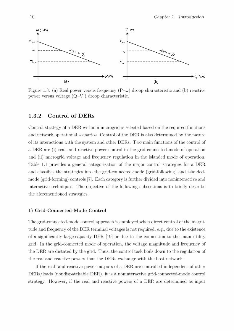
1.3 (a) Real power versus frequency (P–ω) droop characteristic and (b) reac-
tive power versus voltage (Q–V ) droop characteristic. . . . . . . . . . . 10
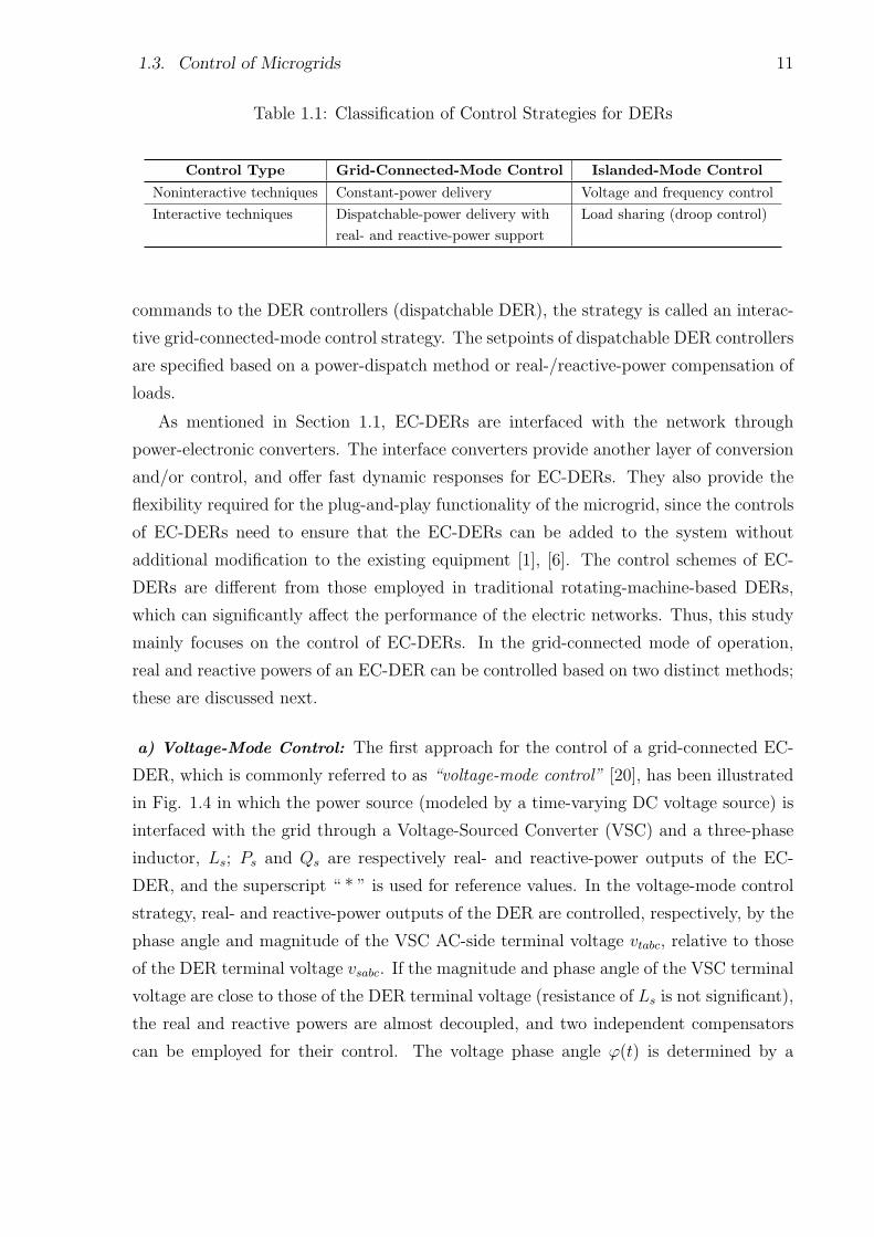
1.4 Voltage-mode control of the real- and reactive-power outputs of a grid-
connected EC-DER. . . . . . . . . . . . . . . . . . . . . . . . . . . . . . 12
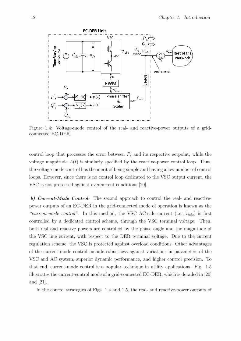
1.5 Current-mode control of the real- and reactive-power outputs of a grid-
connected EC-DER. . . . . . . . . . . . . . . . . . . . . . . . . . . . . . 13
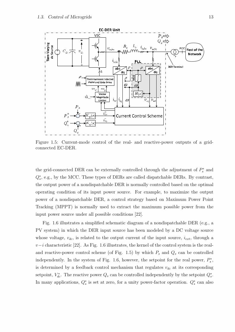
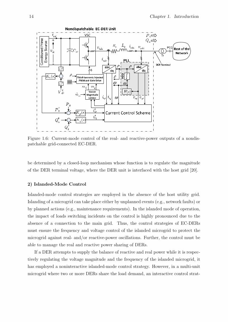
1.6 Current-mode control of the real- and reactive-power outputs of a nondis-
patchable grid-connected EC-DER. . . . . . . . . . . . . . . . . . . . . . 14
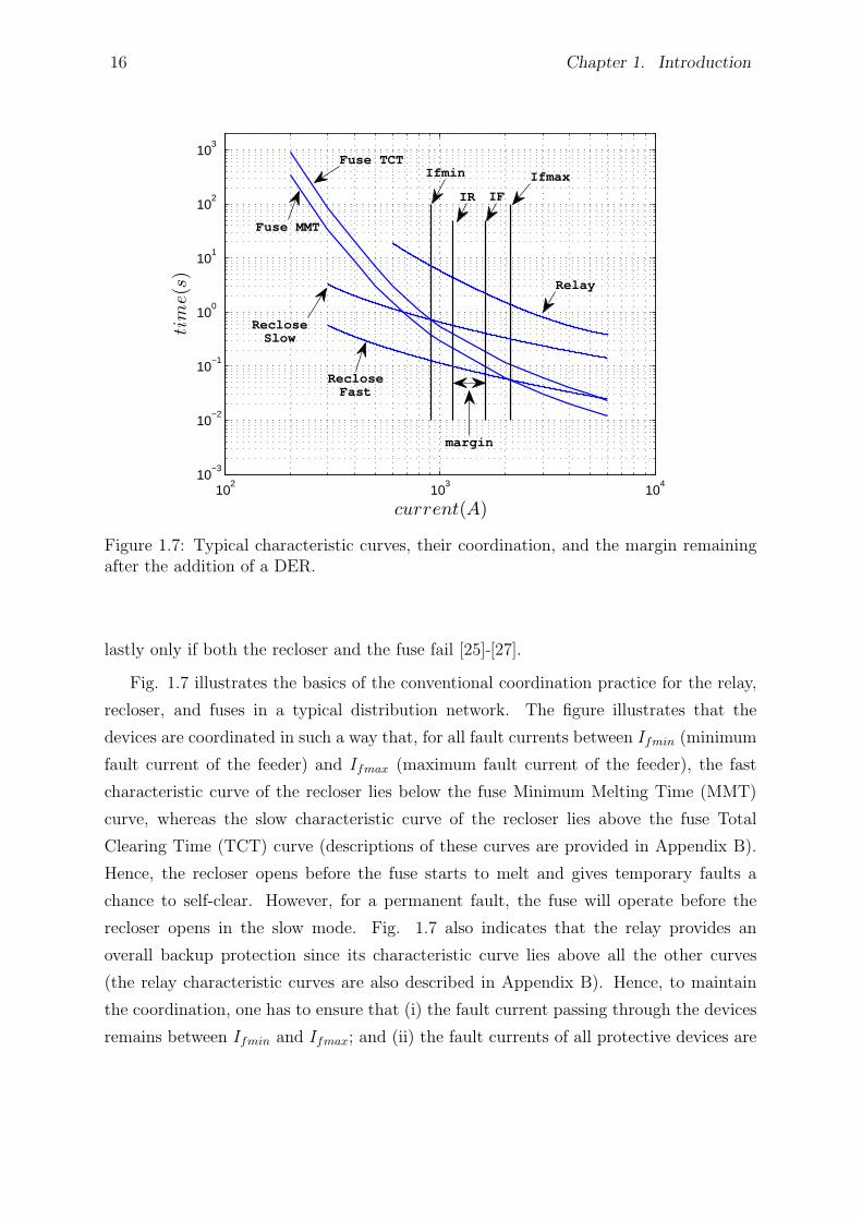
1.7 Typical characteristic curves, their coordination, and the margin remain-
ing after the addition of a DER. . . . . . . . . . . . . . . . . . . . . . . 16
2.1 Schematic diagram of the three-phase EC-DER and its control architec-
ture. . . . . . . . . . . . . . . . . . . . . . . . . . . . . . . . . . . . . . . 27
2.2 Block diagram of the current-control scheme of the three-phase EC-DER. 28
2.3 Block diagram of the voltage magnitude regulation scheme of the three-
phase EC-DER. . . . . . . . . . . . . . . . . . . . . . . . . . . . . . . . 31
2.4 Block diagrams of the equivalent decoupled loops for regulation of vsd and
vsq. . . . . . . . . . . . . . . . . . . . . . . . . . . . . . . . . . . . . . . 31
2.5 Schematic diagram of the PLL. . . . . . . . . . . . . . . . . . . . . . . . 32
2.6 Block diagram of the frequency regulation loop. . . . . . . . . . . . . . . 33
2.7 Block diagram of the enhanced voltage magnitude regulation scheme for
the three-phase EC-DER. . . . . . . . . . . . . . . . . . . . . . . . . . . 34
2.8 Block diagram of the frequency regulation loop, augmented with the pro-
posed phase-angle restoration loop. . . . . . . . . . . . . . . . . . . . . . 37
xi
2.9 Block diagram of the scheme for network-wide and local synchronization
processes: calculation of the (a) frequency setpoint, (b) voltage magnitude
setpoint, and (c) d- and q-axis components of the voltage across the MMS. 38
2.10 Generic model of single-phase EC-DERs. . . . . . . . . . . . . . . . . . 40
2.11 Single-line schematic diagram of the study low-voltage microgrid. . . . . 41
2.12 Waveforms of Bus1 voltage under a transient grid fault at point F1; (a)
basic control and (b) enhanced control. . . . . . . . . . . . . . . . . . . 43
2.13 Real-power output waveforms of the three-phase EC-DERs under a tran-
sient grid fault at point F1; (a) basic control and (b) enhanced control. . 43
2.14 Waveforms of the (a) converter output current and (b) DER output current
under a transient grid fault at point F1 (EC-DER1). . . . . . . . . . . . 44
2.15 Real-power output waveforms of the three-phase EC-DERs during and
subsequent to successful reclosure of the 11-kV line at t=2.5 s; (a) basic
control and (b) enhanced control. . . . . . . . . . . . . . . . . . . . . . . 45
2.16 Waveforms of the magnitude of Bus1 voltage in response to successful
reclosure of the 11-kV line at t=2.5 s; (a) basic control and (b) enhanced
control. . . . . . . . . . . . . . . . . . . . . . . . . . . . . . . . . . . . . 45
2.17 Waveforms of the voltage drop across MMS during the dead time of the
reclosing process; (a) basic control and (b) enhanced control. . . . . . . 46
2.18 Real-power output waveforms of the three-phase EC-DERs under a tem-
porary fault at point F2 of the islanded microgrid; (a) basic control and
(b) enhanced control. . . . . . . . . . . . . . . . . . . . . . . . . . . . . 47
2.19 Waveforms of the phase-angle error for the three-phase EC-DERs under
a temporary fault at point F2 of the islanded microgrid; (a) basic control
and (b) enhanced control. . . . . . . . . . . . . . . . . . . . . . . . . . . 47
2.20 Waveforms of Bus1 voltage under a temporary fault at point F2 of the
islanded microgrid; (a) basic control and (b) enhanced control. . . . . . 48
2.21 Real-power output waveforms of the three-phase EC-DERs under a per-
manent fault at point F3 of the islanded microgrid; (a) basic control and
(b) enhanced control. . . . . . . . . . . . . . . . . . . . . . . . . . . . . 48
2.22 Waveforms of the substation bus voltage under a permanent fault at point
F3 of the islanded microgrid; (a) basic control and (b) enhanced control. 49
xii
2.23 Real-power output waveforms of the three-phase EC-DERs under a per-
manent grid fault at point F1 and successive reclosing; (a) basic control
and (b) enhanced control. . . . . . . . . . . . . . . . . . . . . . . . . . . 50
2.24 Waveform of the voltage across MMS (phase a) during the synchronization
process. . . . . . . . . . . . . . . . . . . . . . . . . . . . . . . . . . . . . 50
2.25 Real- and reactive-power output waveforms of the three-phase DERs dur-
ing the synchronization process. . . . . . . . . . . . . . . . . . . . . . . 51
3.1 Flowchart of the proposed coordination method. . . . . . . . . . . . . . 55
3.2 Single-line schematic diagram of the studied test system. . . . . . . . . . 56
3.3 Equivalent circuit for (IR/IF ) calculation. . . . . . . . . . . . . . . . . . 58
3.4 Coordination of protective devices of Feeder 1 for phase unit. . . . . . . 59
3.5 Coordination of protective devices of Feeder 1 for ground unit. . . . . . 59
3.6 Diagrams showing (a) forward and reverse definite times for relays, and
(b) logics of implementation. . . . . . . . . . . . . . . . . . . . . . . . . 60
3.7 Symbolic logic circuit for substation protection. . . . . . . . . . . . . . . 61
3.8 Curves characterizing the recloser-fuse grading time as a function of (the
inverse of) ZDER2. . . . . . . . . . . . . . . . . . . . . . . . . . . . . . . 62
3.9 Curves characterizing the fuse-fuse grading time as a function of (the in-
verse of) ZDER2. . . . . . . . . . . . . . . . . . . . . . . . . . . . . . . . 63
3.10 Coordination of protective devices of Feeder 2 for phase unit. . . . . . . 64
3.11 Coordination of protective devices of Feeder 2 for ground unit. . . . . . 65
3.12 Coordination of devices when DER2 is not in place. . . . . . . . . . . . 66
3.13 Tripping times of the recloser and fuse when DER2 is not in place. . . . 66
3.14 Coordination loss when DER2 is added to the test system. . . . . . . . . 67
3.15 Tripping times of the recloser and fuse when DER2 is in place. . . . . . 67
3.16 Retrieval of coordination after the addition of DER2. . . . . . . . . . . . 68
3.17 Operation of the recloser in the slow mode when the fuse fails to operate. 68
4.1 The TN-C-S grounding configuration in an LV network. . . . . . . . . . 72
4.2 Diagram showing the coordination of MPRs in the islanded mode of op-
eration. . . . . . . . . . . . . . . . . . . . . . . . . . . . . . . . . . . . . 77
4.3 Symbolic logic circuit for substation bus protection. . . . . . . . . . . . 79
4.4 Extending the protection scheme for SMs including four MPRs. . . . . . 80
xiii
4.5 Traditional coordination of fuses and relays in a typical distribution net-
work. . . . . . . . . . . . . . . . . . . . . . . . . . . . . . . . . . . . . . 81
4.6 Coordination of the IMPR and MPRs for an external (grid) fault. . . . 83
4.7 Simplified schematic diagram of the proposed MPR (or IMPR). . . . . . 84
4.8 Single-line diagram of the study LV microgrid. . . . . . . . . . . . . . . 86
5.1 Single-line diagram of a typical medium-voltage distribution network and
its conventional protection devices. . . . . . . . . . . . . . . . . . . . . . 95
5.2 The network of Fig. 5.1 that is equipped with DERs and can be operated
as an MV microgrid. . . . . . . . . . . . . . . . . . . . . . . . . . . . . . 96
5.3 Simplified schematic diagram of an MPR/CMPR. . . . . . . . . . . . . . 97
5.4 Concept of a Delta-Filter for a time-varying waveform: (a) continuous-
time form, and (b) discrete-time form. . . . . . . . . . . . . . . . . . . . 99
5.5 Flowchart of the proposed protection scheme. . . . . . . . . . . . . . . . 104
5.6 Schematic Diagram of the WLAN communication protocol, augmented
with wireless Ethernet Bridges, for the proposed protection strategy im-
plemented in an example microgrid. . . . . . . . . . . . . . . . . . . . . 106
5.7 Single-line diagram of the study microgrid with the embedded MPRs and
CMPRs. . . . . . . . . . . . . . . . . . . . . . . . . . . . . . . . . . . . 108
5.8 Grading scheme of the study microgrid relays for the backup protection
strategy. . . . . . . . . . . . . . . . . . . . . . . . . . . . . . . . . . . . 110
6.1 Single-line schematic diagram of the study system. . . . . . . . . . . . . 119
6.2 Schematic diagram of a DFIG wind-power unit. . . . . . . . . . . . . . . 123
6.3 Single-line schematic diagram of the study system with the wind farm and
the BESS. . . . . . . . . . . . . . . . . . . . . . . . . . . . . . . . . . . . 125
6.4 Droop-based power management strategy; (a) real power compensator
with synchronization function and (b) reactive power compensator with
synchronization function. . . . . . . . . . . . . . . . . . . . . . . . . . . 127
6.5 (a) Conventional pitch-angle control scheme and (b) proposed pitch-angle
control scheme, for the wind-power units. . . . . . . . . . . . . . . . . . 128
6.6 Simplified schematic diagram of the MPR employed in this chapter. . . 133
6.7 Case 1: operation in the grid-connected mode; (a) with synchronous DER
and (b) with EC-DER. . . . . . . . . . . . . . . . . . . . . . . . . . . . 134
xiv
6.8 Case 2: operation in the islanded mode; (a) with synchronous DER and
(b) with EC-DER. . . . . . . . . . . . . . . . . . . . . . . . . . . . . . . 135
6.9 Case 3: system response to a temporary fault in the islnaded mode; (a)
with synchronous DER and (b) with EC-DER. . . . . . . . . . . . . . . 136
6.10 Case 3: system response to a permanent fault in the islnaded mode; (a)
with synchronous DER and (b) with EC-DER. . . . . . . . . . . . . . . 137
6.11 Case 4: synchronization process; (a) with synchronous DER and (b) with
EC-DER. . . . . . . . . . . . . . . . . . . . . . . . . . . . . . . . . . . . 138
6.12 Case 5: system response under environmental changes in the islanded
mode of operation (Scenario 2 of Section 6.4). . . . . . . . . . . . . . . . 139
6.13 Case 5: system response when the pitch-angle control takes action in the
islanded mode of operation (Scenario 2 of Section 6.4). . . . . . . . . . . 139
6.14 Coordination of the recloser and fuse of the study system in the grid-
connected mode; (a) phase element and (b) ground element. . . . . . . . 141
6.15 Diagram showing the coordination of digital relays within the study sys-
tem. . . . . . . . . . . . . . . . . . . . . . . . . . . . . . . . . . . . . . . 142
B.1 Characteristic of the directional element (phase comparison). . . . . . . 154
xv
List of Tables
1.1 Classification of Control Strategies for DERs . . . . . . . . . . . . . . . . 11
3.1 Fault Calculation Results for the Test System . . . . . . . . . . . . . . . 58
4.1 Currents Required for Safe Operation of Household Fuses in 5 Cycles (83
ms) from the Fault Inception . . . . . . . . . . . . . . . . . . . . . . . . . 74
4.2 Operating Times of Primary and Backup Protection for Selected Solid
Fault Scenarios in the Islanded Mode of Operation . . . . . . . . . . . . 89
4.3 Operating Times of Primary and Backup Protection for Selected High-
Impedance Fault Scenarios in the Islanded Mode of Operation . . . . . . 90
4.4 Operating Times of Primary and Backup Protection for Selected Solid
Fault Scenarios in the Grid-Connected Mode of Operation . . . . . . . . 91
4.5 Operating Times of Primary and Backup Protection for Selected High-
Impedance Fault Scenarios in the Grid-Connected Mode of Operation . . 92
5.1 Logics for Detecting and Isolating a Fault within the Study Microgrid . . 109
5.2 Operating Times of Main and Backup Protections for Selected Solid Fault
Scenarios in the Islanded Mode of Operation . . . . . . . . . . . . . . . . 113
5.3 Operating Times of Main and Backup Protections for Selected High-Impedance
Fault Scenarios in the Islanded Mode of Operation . . . . . . . . . . . . 114
5.4 Operating Times of Main and Backup Protections for Selected Solid Fault
Scenarios in the Grid-Connected Mode of Operation . . . . . . . . . . . . 115
5.5 Operating Times of Main and Backup Protections for Selected High-Impedance
Fault Scenarios in the Grid-Connected Mode of Operation . . . . . . . . 116
6.1 Operating Times of the Main and Backup Protection for Selected Fault
Scenarios in the Grid-Connected Mode of Operation (with OCRs) . . . . 144
6.2 Operating Times of the Main and Backup Protection for Selected Fault
Scenarios in the Grid-Connected Mode of Operation (with MPRs) . . . . 144
xvi
6.3 Operating Times of the Main and Backup Protection for Selected Fault
Scenarios in the Islanded Mode of Operation (with OCRs) . . . . . . . . 145
6.4 Operating Times of the Main and Backup Protection for Selected Fault
Scenarios in the Islanded Mode of Operation (with MPRs) . . . . . . . . 145
A.1 Parameters of the Three-Phase EC-DERs . . . . . . . . . . . . . . . . . . 151
B.1 Coefficients of Fuse Characteristic Curves . . . . . . . . . . . . . . . . . . 153
C.1 Time Delays for MPRs . . . . . . . . . . . . . . . . . . . . . . . . . . . . 156
C.2 Time Delays for the IMPR . . . . . . . . . . . . . . . . . . . . . . . . . . 156
C.3 Inverse-Time Overcurrent Relay Parameters for MPRs and the IMPR . . 156
C.4 Three-Phase Protection Module Parameters for MPRs and the IMPR . . 157
C.5 Device/Function Numbers . . . . . . . . . . . . . . . . . . . . . . . . . . 157
D.1 Bus Loads for the Distribution Network of Fig. 5.1. . . . . . . . . . . . . 159
D.2 Relay Signals . . . . . . . . . . . . . . . . . . . . . . . . . . . . . . . . . 159
E.1 Parameters of the Wind Turbine. . . . . . . . . . . . . . . . . . . . . . . 160
E.2 Parameters of the DFIG Unit. . . . . . . . . . . . . . . . . . . . . . . . . 161
E.3 Parameters of the Synchronous DER. . . . . . . . . . . . . . . . . . . . . 161
xvii
List of Appendices
Appendix A Specifications of the EC-DERs of Chapter 2 . . . . . . . . . . . . . . 150
Appendix B Modeling of Protective Devices . . . . . . . . . . . . . . . . . . . . . 152
Appendix C Relay Settings and Device Numbers for Chapter 4 . . . . . . . . . . 155
Appendix D Load and Relay Parameters for Chapter 5 . . . . . . . . . . . . . . . 158
Appendix E DER Parameters for Chapter 6 . . . . . . . . . . . . . . . . . . . . . 160
xviii

Abbreviations and Symbols
AC Alternating Current
BESS Battery Energy Storage System
CB Circuit Breaker
CHP Combined Heat and Power
CMPR Communication-Assisted Microgrid Protection Relay
D fault Direction signal
DC Direct Current
DER Distributed Energy Resource
DES Distributed Energy Storage devices
DFIG Doubly-Fed Induction Generator
DG Distributed Generator
DMS Distribution Management System
DNO Distribution Network Operator
EC-DER Electronically Coupled Distributed Energy Resource
ES Ethernet Switch
FCL Fault Current Limiter
FD Fault Detection signal
GSC Grid-Side Converter
GY Grounded Wye (grounded star)
HIF High-Impedance Fault
IMPR Interface Microgrid Protection Relay
LANP Local Area Network Port
LC Local Controller
LDRC Local Distributed energy Resource Controllers
LLC Local Load Controllers
LV Low Voltage
MCC Microgrid Central Controller
MMS Main Microgrid Switch
MMT Minimum Melting Time
MO Market Operator
MPC Microgrid Protection Commander
MPPT Maximum Power Point Tracking
MPR Microgrid Protection Relay
xix

MV Medium Voltage
NVD Neutral Voltage Displacement
OC OverCurrent
OCR OverCurrent Relay
PI Proportional-Integral
PLL Phase-Locked Loop
PCC Point of Common Coupling
PSCAD Power System Computer-Aided Design
PV Photovoltaic
PWM Pulse-Width Modulation
RSC Rotor-Side Converter
RTDS Real-Time Digital Simulator
SM Secondary Main
TCT Total Clearing Time
VCO Voltage-Controlled Oscillator
VSC Voltage-Sourced Converter
WEB Wireless Ethernet Bridge
WLAN Wireless Local Area Network
xx
Nomenclature
itabc VSC AC-side current
isabc DER output current
iext Output current of the DER input source
vtabc VSC AC-side terminal voltage
vsabc DER terminal voltage
vdc DC-link voltage
vMabc Microgrid-side voltage of the MMS
vGabc Grid-side voltage of the MMS
vMMS Voltage across the MMS
Ps Output real power of the DER
Qs Output reactive power of the DER
Pext Exogenous input power to the single-phase DER
Cdc DC-link capacitance
Cs Capacitance of the DER LC filter
Ls Inductance of the DER LC filter
Rs Parasitic resistance of Ls (including on-state resistance of VSC switches)
DP Real power droop coefficient
DQ Reactive power droop coefficient
Ifmax Maximum fault current of the feeder
Ifmin Minimum fault current of the feeder
Te Machine electrical torque
vW Wind speed
V0 Nominal network voltage magnitude
ω0 Nominal power system frequency
ωr Machine rotor angular speed
β Blade pitch angle
ρ dq-frame reference angle
Ts Sampling period
fs Sampling/switching frequency
xxi
Chapter 1
Introduction
1.1 Statement of Problem and Research Objectives
A microgrid is broadly referred to as a well-defined area of an electric distribution network
which embeds an appreciable number of distributed energy resources, in addition to
local loads; it is managed and controlled by an intelligence and would be capable of
operating in isolation from the host utility grid (islanded mode of operation), as well as
in conjunction with the grid (grid-connected mode of operation). A microgrid can be
a residential neighborhood, an industrial or commercial facility, a university campus, a
hospital, an off-grid remote community, etc. The microgrid could be forced to switch to
the islanded mode of operation, for example, due to the occurrence of a fault in the host
grid, or it could intentionally disconnect itself from the grid, for example, if economics
warrant the islanded mode of operation [1]. Regardless, the microgrid is expected to
ensure efficient service to the microgrid loads, with superior quality and reliability, in
addition to economical benefit for the microgrid owner, as well as ancillary services to
the host grid.
Despite their perceived advantages, microgrids introduce new and serious challenges
to distribution networks. However, the economical and environmental benefits of micro-
grids have motivated extensive research and development efforts towards resolving the
technical issues associated with this new and fast-growing technology. The distributed
energy resources are required to collectively control the network voltage and frequency,
properly share the network power demand, ride through faults and disturbances, and en-
able seamless transitions of the microgrid from the grid-connected mode of operation to
the islanded mode of operation, and vice versa. These requirements present a challenge
1
2 Chapter 1. Introduction
to the control of microgrids and their constituent distributed energy resources [2]. In
addition, adoption of the microgrid concept results in a cellular structure within distri-
bution networks; thus, it warrants a revision of the traditional philosophy of protection
which assumes a radial network structure with a unidirectional flow of power [3], [4].
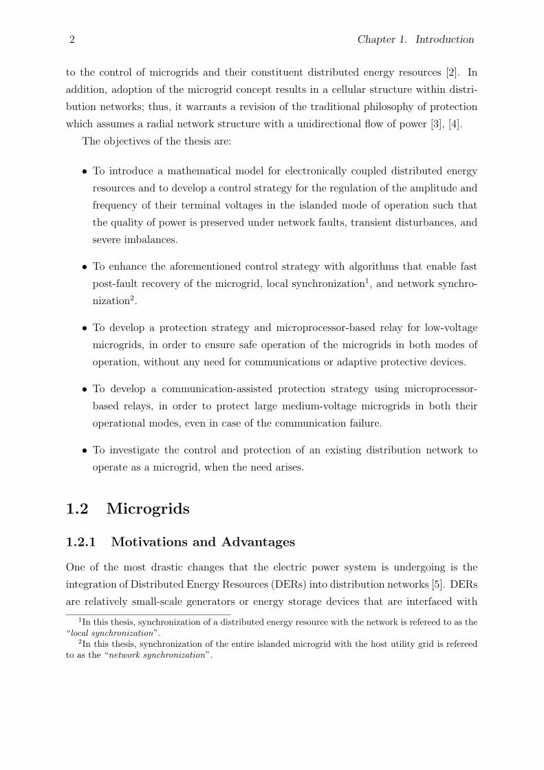
The objectives of the thesis are:
• To introduce a mathematical model for electronically coupled distributed energy
resources and to develop a control strategy for the regulation of the amplitude and
frequency of their terminal voltages in the islanded mode of operation such that
the quality of power is preserved under network faults, transient disturbances, and
severe imbalances.
• To enhance the aforementioned control strategy with algorithms that enable fast
post-fault recovery of the microgrid, local synchronization1, and network synchro-
nization2.
• To develop a protection strategy and microprocessor-based relay for low-voltage
microgrids, in order to ensure safe operation of the microgrids in both modes of
operation, without any need for communications or adaptive protective devices.
• To develop a communication-assisted protection strategy using microprocessor-
based relays, in order to protect large medium-voltage microgrids in both their
operational modes, even in case of the communication failure.
• To investigate the control and protection of an existing distribution network to
operate as a microgrid, when the need arises.
1.2 Microgrids
1.2.1 Motivations and Advantages
One of the most drastic changes that the electric power system is undergoing is the
integration of Distributed Energy Resources (DERs) into distribution networks [5]. DERs
are relatively small-scale generators or energy storage devices that are interfaced with
1In this thesis, synchronization of a distributed energy resource with the network is refereed to as the“local synchronization”.
2In this thesis, synchronization of the entire islanded microgrid with the host utility grid is refereedto as the “network synchronization”.
1.2. Microgrids 3
low-/medium-voltage distribution networks and can offset the local power consumption,
or even export power to the upstream network if their generation surpasses the local
consumption. Most modern DERs employ non-conventional energy resources and are
interfaced with the host utility grid through power-electronic converters, as efforts are
made to utilize renewable or sustainable energy sources. The increasing proliferation
of Electronically Coupled DERs (EC-DERs), such as photovoltaic systems, micro-gas
turbines, wind power systems, and battery energy systems, is expected to inevitably
challenge the operating principles of the traditional power systems.
An emerging and promising philosophy of operation to mitigate the technical issues
associated with widespread proliferation of DERs, and to offer additional value, is to
designate relatively small areas of a distribution network that embed DERs and loads,
and to operate them in a deliberate and controlled way. Such subnetworks, referred to
as microgrids, should be able to operate independently (under emergency conditions or
as planned), as well as in parallel with the rest of the distribution network. The con-
cept of microgrid has attracted considerable attention due to its potential to integrate
large amounts of renewable energy resources into the electric power system, without com-
promising the power quality, while promising to maintain supply reliability, to enhance
energy conversion efficiency, and to provide ancillary services to the power system [6].
One of the main benefits of microgrids is the use of Combined Heat and Power (CHP)
equipment that makes the microgrid an integrated energy system with high energy effi-
ciency. The waste heat from the conversion of fuel to electrical power in small generators
can be used by local consumers, through the CHP technology, to raise the DER effi-
ciency [6], [7]. In addition, most DERs of a microgrid are of electronically coupled type
which can rapidly correct voltage sags, harmonics, etc., even in the presence of nonlinear
and/or unbalanced loads; this, in turn, leads to an improved power quality. Morover, the
proximity between generation and consumption can improve the reliability of service to
sensitive loads. Reliability is further enhanced by diversification and decentralization of
the supply; thus, loss of one unit can be compensated for by the other units [1].
As mentioned earlier, microgrids are envisioned to embed a great deal of EC-DERs to
play a significant role in the electric power systems of the future for cleaner air, reduced
transmission and distribution costs, and enablement of energy efficiency enhancement
initiatives. The use of clean and renewable energy resources can substantially reduce
greenhouse gas emissions. The environmental issues have become exceedingly important
in developed countries. For example, according to a 2005 study prepared for the govern-
4 Chapter 1. Introduction
ment of Canada, the health-related damages of coal-fired plants could exceed 3 billion
dollars a year [8]. Therefore, building clean and sustainable sources of electricity is a top
priority for the Canadian government. Smaller generators have also economical benefits
such as shorter construction times and transmission lines [9].
1.2.2 Architecture
The main components of a microgrid are distributed generators (wind turbines, photo-
voltaic arrays, rotating machines, fuel cells, etc.), distributed energy storage devices (fly-
wheels, batteries, supercapacitors, compressed-air systems, etc.), and local critical/non-
critical loads. Distributed Generators (DGs) can generally be classified into two main
groups, based on their interfacing media: (i) traditional rotating-machine-based DGs and
(ii) electronically interfaced DGs. The first group are those that consist of direct-coupled
rotating machines and are directly interfaced to the network through interconnection
transformers (e.g., a synchronous generator driven by a reciprocating engine or an induc-
tion generator driven by a fixed-speed wind turbine). The second group, however, utilizes
DC/AC or AC/DC/AC power-electronic converters as their coupling media with the host
grid (e.g., photovoltaic systems or variable-speed wind energy conversion systems). The
control techniques and characteristics of power-electronic converters are significantly dif-
ferent than those of the conventional rotating machines [10]. Moreover, due to the limited
current rating of silicon devices, the fault current of electronically interfaced DGs should
be limited to a maximum of about two times their nominal current [4].
Distributed Energy Storage devices (DESs) are mainly employed as energy-backup
systems to compensate for the power shortage within the microgrid, particularly in the
islanded mode of operation when the generators may not be able to satisfy the entire load
power demand. They can also be employed in the grid-connected mode of operation to
smooth out the intermittent power of renewable energy resources and/or to incorporate
significant load changes [11]. Since, due to their inherent large time constants, traditional
rotating-machine-based DGs cannot rapidly respond to power intermittencies, instability
may occur in transient situations. Thus, the use of DESs is necessary to prevent such an
issue. A DES is modeled in this thesis as a constant DC voltage source interfaced with
the utility grid through a power-electronic converter. It acts as a controllable AC voltage
sources (with very fast output characteristics) to face sudden system changes such as load
or operational mode switchings. It should be noted that all DESs have a finite capacity
for storing energy and, thus, can be in service for a limited period of time.
1.2. Microgrids 5
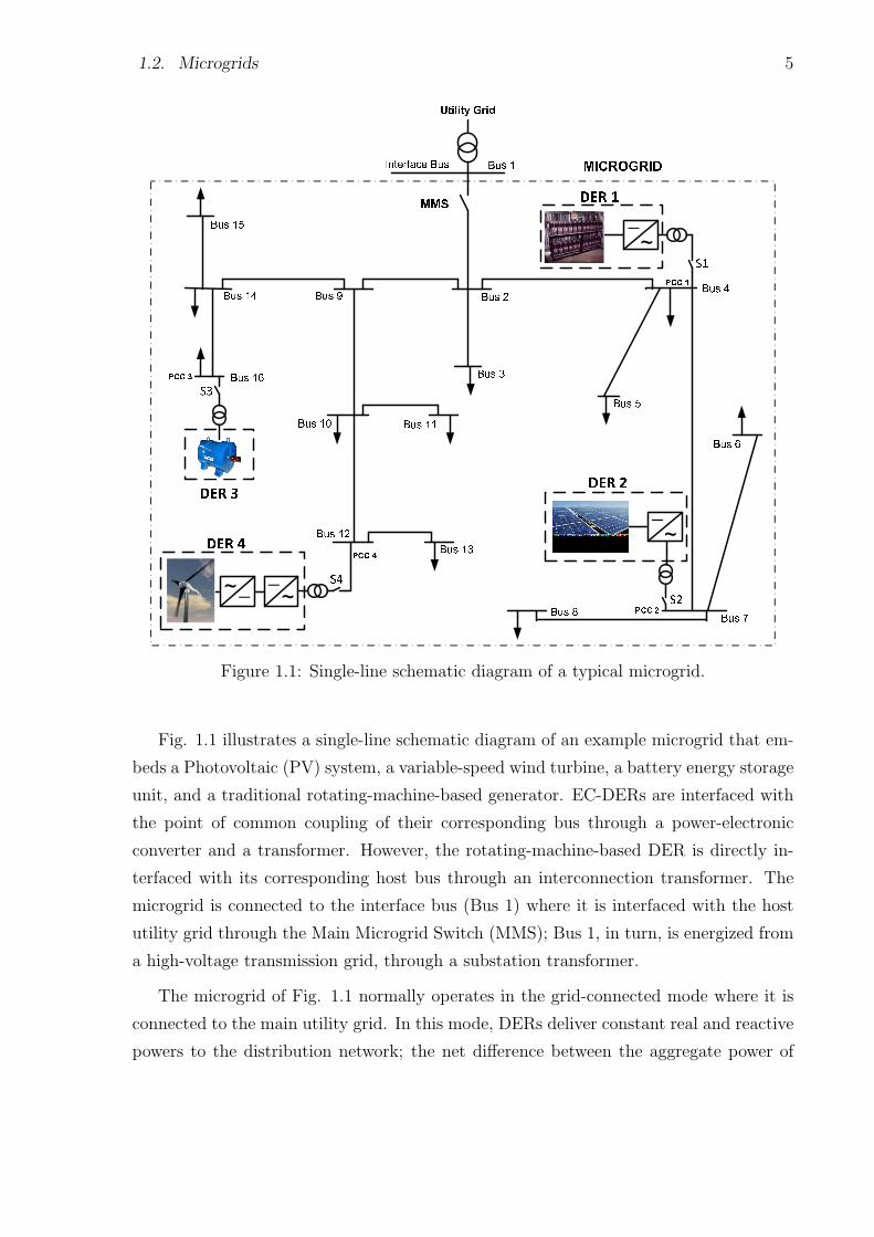
Figure 1.1: Single-line schematic diagram of a typical microgrid.
Fig. 1.1 illustrates a single-line schematic diagram of an example microgrid that em-
beds a Photovoltaic (PV) system, a variable-speed wind turbine, a battery energy storage
unit, and a traditional rotating-machine-based generator. EC-DERs are interfaced with
the point of common coupling of their corresponding bus through a power-electronic
converter and a transformer. However, the rotating-machine-based DER is directly in-
terfaced with its corresponding host bus through an interconnection transformer. The
microgrid is connected to the interface bus (Bus 1) where it is interfaced with the host
utility grid through the Main Microgrid Switch (MMS); Bus 1, in turn, is energized from
a high-voltage transmission grid, through a substation transformer.
The microgrid of Fig. 1.1 normally operates in the grid-connected mode where it is
connected to the main utility grid. In this mode, DERs deliver constant real and reactive
powers to the distribution network; the net difference between the aggregate power of
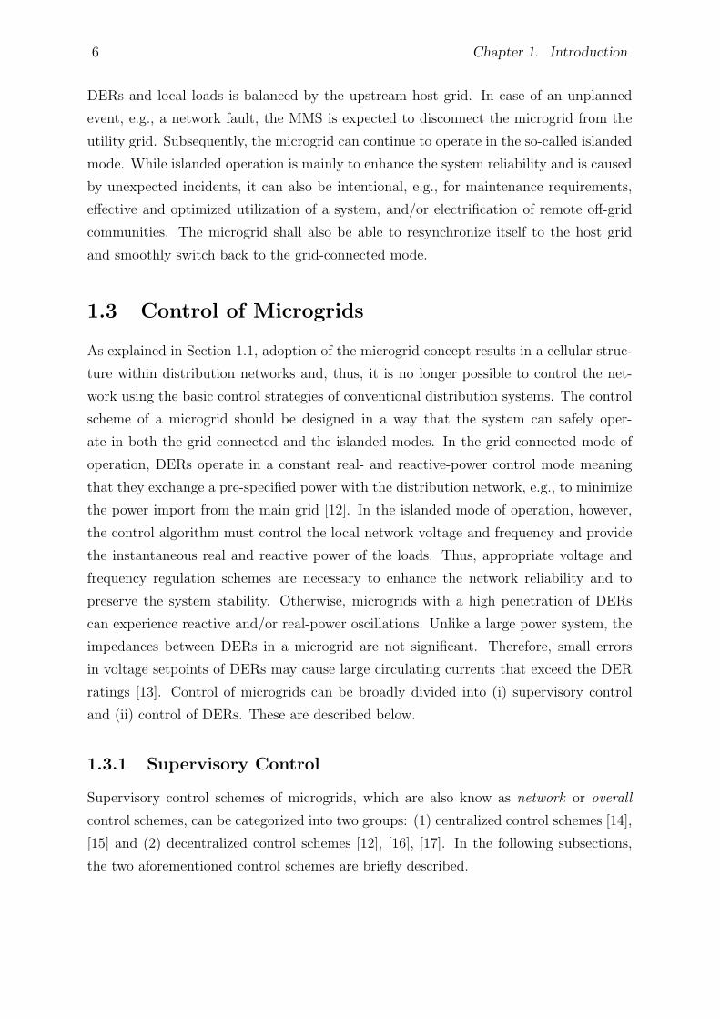
6 Chapter 1. Introduction
DERs and local loads is balanced by the upstream host grid. In case of an unplanned
event, e.g., a network fault, the MMS is expected to disconnect the microgrid from the
utility grid. Subsequently, the microgrid can continue to operate in the so-called islanded
mode. While islanded operation is mainly to enhance the system reliability and is caused
by unexpected incidents, it can also be intentional, e.g., for maintenance requirements,
effective and optimized utilization of a system, and/or electrification of remote off-grid
communities. The microgrid shall also be able to resynchronize itself to the host grid
and smoothly switch back to the grid-connected mode.
1.3 Control of Microgrids
As explained in Section 1.1, adoption of the microgrid concept results in a cellular struc-
ture within distribution networks and, thus, it is no longer possible to control the net-
work using the basic control strategies of conventional distribution systems. The control
scheme of a microgrid should be designed in a way that the system can safely oper-
ate in both the grid-connected and the islanded modes. In the grid-connected mode of
operation, DERs operate in a constant real- and reactive-power control mode meaning
that they exchange a pre-specified power with the distribution network, e.g., to minimize
the power import from the main grid [12]. In the islanded mode of operation, however,
the control algorithm must control the local network voltage and frequency and provide
the instantaneous real and reactive power of the loads. Thus, appropriate voltage and
frequency regulation schemes are necessary to enhance the network reliability and to
preserve the system stability. Otherwise, microgrids with a high penetration of DERs
can experience reactive and/or real-power oscillations. Unlike a large power system, the
impedances between DERs in a microgrid are not significant. Therefore, small errors
in voltage setpoints of DERs may cause large circulating currents that exceed the DER
ratings [13]. Control of microgrids can be broadly divided into (i) supervisory control
and (ii) control of DERs. These are described below.
1.3.1 Supervisory Control
Supervisory control schemes of microgrids, which are also know as network or overall
control schemes, can be categorized into two groups: (1) centralized control schemes [14],
[15] and (2) decentralized control schemes [12], [16], [17]. In the following subsections,
the two aforementioned control schemes are briefly described.
1.3. Control of Microgrids 7
1) Centralized Control
For the overall control of a microgrid, three control levels are typically defined:
• Local Controllers (LCs), which could be either Local DER Controllers (LDRCs) or
Local Load Controllers (LLCs);
• Microgrid Central Controller (MCC);
• Distribution Management System (DMS).
The LCs are assumed to control DERs and controllable loads within a microgrid, by
tracking desired commands. In a centralized mode of control, the LCs receive their com-
mands from the MCC; thus, the MCC issues control setpoints to DERs and controllable
loads through a communication link. The commands are determined based on a variety
of criteria, such as market signals and economy of the microgrid; optimal operation of
the microgrid; host grid conditions and requirements; and microgrid internal conditions
and requirements [14]. Therefore, the MCC is assumed to take different roles ranging
from the optimization of the microgrid key parameters to coordination of LCs. It should
be noted that, depending on the control approach, each LC may also have a certain level
of intelligence.
In the grid-connected mode of operation, the microgrid voltage is imposed by the
host utility grid and, thus, the function of the supervisory control is to issue the real-
and reactive-power commands to the LDRCs. By contrast, in the islanded mode of
operation, the DERs are mainly controlled to regulate the microgrid voltage magnitude
and frequency. Consequently, the supervisory control can specify the commands for
steady-state voltage magnitude and frequencies of the DERs, ensuring well being of the
loads or safe reconnection of the microgrid to the host grid once the operating mode is to
be switched to the grid-connected mode. Further, the supervisory control can shed loads
in the islanded mode of operation, depending on load criteria, microgrid energy reserves,
or other considerations. Finally, the DMS1 is a higher level of controller responsible
for the technical operation in a medium- and low-voltage area, in which more than one
microgrid exist [7]. Thus, the DMS does not belong to one microgrid and is interfaced
with the microgrid through its corresponding MCC. Fig. 1.2 illustrates the hierarchical
control system architecture of the microgrid of Fig. 1.1.
1This high-level controller is also referred to as the “Distribution Network Operator (DNO)” or “Mar-ket Operator (MO)”, in some references [15].
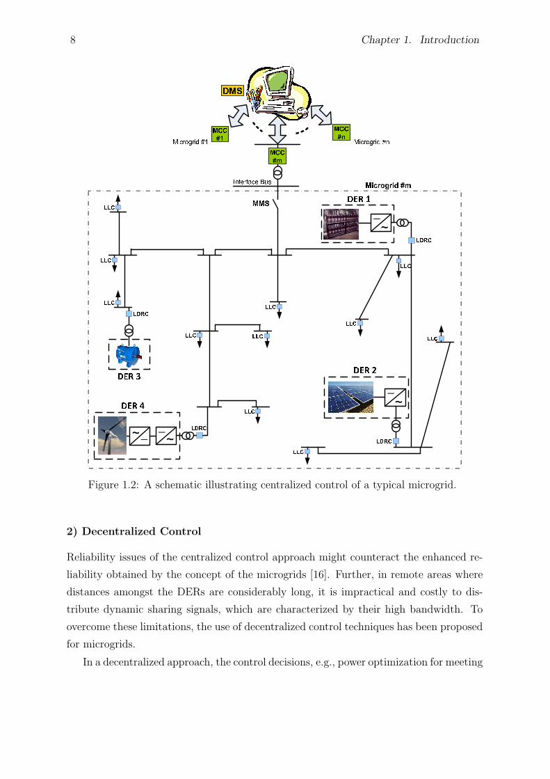
8 Chapter 1. Introduction
Figure 1.2: A schematic illustrating centralized control of a typical microgrid.
2) Decentralized Control
Reliability issues of the centralized control approach might counteract the enhanced re-
liability obtained by the concept of the microgrids [16]. Further, in remote areas where
distances amongst the DERs are considerably long, it is impractical and costly to dis-
tribute dynamic sharing signals, which are characterized by their high bandwidth. To
overcome these limitations, the use of decentralized control techniques has been proposed
for microgrids.
In a decentralized approach, the control decisions, e.g., power optimization for meeting
1.3. Control of Microgrids 9
load demands or maximizing power export to the main grid based on the market prices,
are made by the LDRCs [17]. Moreover, LLCs are assumed to ensure safe and smooth
operation of the loads that they control. In such systems, each unit must be able to
operate independently without intercommunications. The main task of each LC in a
decentralized control scheme is not to only maximize the revenue of its corresponding
unit but to also improve the overall performance of the microgrid. Thus, the control
system architecture must be able to include economic functions, environmental factors,
and technical requirements [7].
The most widely adopted decentralized technique to ensure power sharing and co-
ordinated voltage/frequency regulation is to droop the frequency and magnitude of the
output voltage of each DER, versus the real and reactive powers that the DER deliv-
ers to the network [18]. Thus, the DER controllers typically make their adjustments
based on the frequency and magnitude of the inverter terminal voltage. The frequency
droop allows the DERs to share the total real power variations in a manner determined
by their frequency droop characteristic; it essentially utilizes the system frequency as a
communication link between the DER control systems. Similarly, a droop in the voltage
amplitude, with respect to reactive power, can ensure reactive power sharing. This load
sharing technique is based on the power flow theory in an AC system, which states that
the flow of the real and reactive powers between two sources can be controlled by ad-
justing the power angle and the voltage magnitude of the systems, respectively. In the
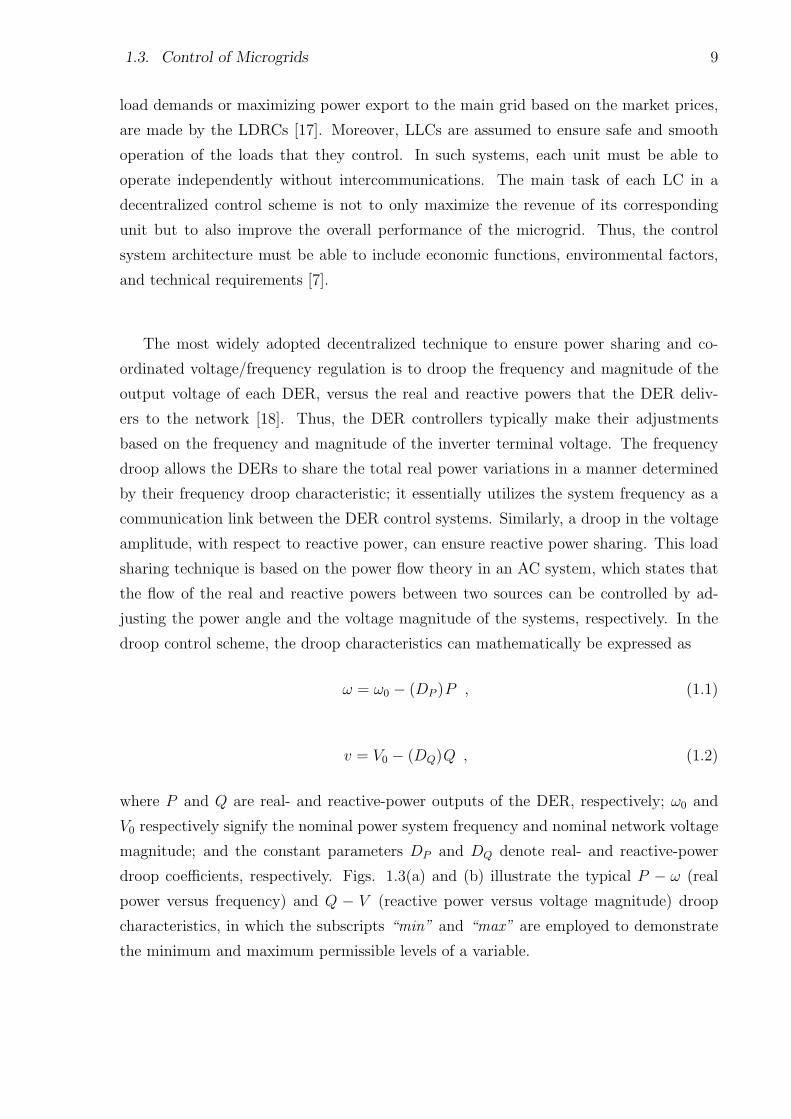
droop control scheme, the droop characteristics can mathematically be expressed as
ω = ω0 − (DP )P , (1.1)
v = V0 − (DQ)Q , (1.2)
where P and Q are real- and reactive-power outputs of the DER, respectively; ω0 and
V0 respectively signify the nominal power system frequency and nominal network voltage
magnitude; and the constant parameters DP and DQ denote real- and reactive-power
droop coefficients, respectively. Figs. 1.3(a) and (b) illustrate the typical P − ω (real
power versus frequency) and Q − V (reactive power versus voltage magnitude) droop
characteristics, in which the subscripts “min” and “max” are employed to demonstrate
the minimum and maximum permissible levels of a variable.
10 Chapter 1. Introduction
Figure 1.3: (a) Real power versus frequency (P–ω) droop characteristic and (b) reactivepower versus voltage (Q–V ) droop characteristic.
1.3.2 Control of DERs
Control strategy of a DER within a microgrid is selected based on the required functions
and network operational scenarios. Control of the DER is also determined by the nature
of its interactions with the system and other DERs. Two main functions of the control of
a DER are (i) real- and reactive-power control in the grid-connected mode of operation
and (ii) microgrid voltage and frequency regulation in the islanded mode of operation.
Table 1.1 provides a general categorization of the major control strategies for a DER
and classifies the strategies into the grid-connected-mode (grid-following) and islanded-
mode (grid-forming) controls [7]. Each category is further divided into noninteractive and
interactive techniques. The objective of the following subsections is to briefly describe
the aforementioned strategies.
1) Grid-Connected-Mode Control
The grid-connected-mode control approach is employed when direct control of the magni-
tude and frequency of the DER terminal voltages is not required, e.g., due to the existence
of a significantly large-capacity DER [19] or due to the connection to the main utility
grid. In the grid-connected mode of operation, the voltage magnitude and frequency of
the DER are dictated by the grid. Thus, the control task boils down to the regulation of
the real and reactive powers that the DERs exchange with the host network.
If the real- and reactive-power outputs of a DER are controlled independent of other
DERs/loads (nondispatchable DER), it is a noninteractive grid-connected-mode control
strategy. However, if the real and reactive powers of a DER are determined as input
1.3. Control of Microgrids 11
Table 1.1: Classification of Control Strategies for DERs
Control Type Grid-Connected-Mode Control Islanded-Mode Control
Noninteractive techniques Constant-power delivery Voltage and frequency control
Interactive techniques Dispatchable-power delivery with Load sharing (droop control)
real- and reactive-power support
commands to the DER controllers (dispatchable DER), the strategy is called an interac-
tive grid-connected-mode control strategy. The setpoints of dispatchable DER controllers
are specified based on a power-dispatch method or real-/reactive-power compensation of
loads.
As mentioned in Section 1.1, EC-DERs are interfaced with the network through
power-electronic converters. The interface converters provide another layer of conversion
and/or control, and offer fast dynamic responses for EC-DERs. They also provide the
flexibility required for the plug-and-play functionality of the microgrid, since the controls
of EC-DERs need to ensure that the EC-DERs can be added to the system without
additional modification to the existing equipment [1], [6]. The control schemes of EC-
DERs are different from those employed in traditional rotating-machine-based DERs,
which can significantly affect the performance of the electric networks. Thus, this study
mainly focuses on the control of EC-DERs. In the grid-connected mode of operation,
real and reactive powers of an EC-DER can be controlled based on two distinct methods;
these are discussed next.
a) Voltage-Mode Control: The first approach for the control of a grid-connected EC-
DER, which is commonly referred to as “voltage-mode control” [20], has been illustrated
in Fig. 1.4 in which the power source (modeled by a time-varying DC voltage source) is
interfaced with the grid through a Voltage-Sourced Converter (VSC) and a three-phase
inductor, Ls; Ps and Qs are respectively real- and reactive-power outputs of the EC-
DER, and the superscript “ * ” is used for reference values. In the voltage-mode control
strategy, real- and reactive-power outputs of the DER are controlled, respectively, by the
phase angle and magnitude of the VSC AC-side terminal voltage vtabc, relative to those
of the DER terminal voltage vsabc. If the magnitude and phase angle of the VSC terminal
voltage are close to those of the DER terminal voltage (resistance of Ls is not significant),
the real and reactive powers are almost decoupled, and two independent compensators
can be employed for their control. The voltage phase angle φ(t) is determined by a
12 Chapter 1. Introduction
Figure 1.4: Voltage-mode control of the real- and reactive-power outputs of a grid-connected EC-DER.
control loop that processes the error between Ps and its respective setpoint, while the
voltage magnitude A(t) is similarly specified by the reactive-power control loop. Thus,
the voltage-mode control has the merit of being simple and having a low number of control
loops. However, since there is no control loop dedicated to the VSC output current, the
VSC is not protected against overcurrent conditions [20].
b) Current-Mode Control: The second approach to control the real- and reactive-
power outputs of an EC-DER in the grid-connected mode of operation is known as the
“current-mode control”. In this method, the VSC AC-side current (i.e., itabc) is first
controlled by a dedicated control scheme, through the VSC terminal voltage. Then,
both real and reactive powers are controlled by the phase angle and the magnitude of
the VSC line current, with respect to the DER terminal voltage. Due to the current
regulation scheme, the VSC is protected against overload conditions. Other advantages
of the current-mode control include robustness against variations in parameters of the
VSC and AC system, superior dynamic performance, and higher control precision. To
that end, current-mode control is a popular technique in utility applications. Fig. 1.5
illustrates the current-control mode of a grid-connected EC-DER, which is detailed in [20]
and [21].
In the control strategies of Figs. 1.4 and 1.5, the real- and reactive-power outputs of
1.3. Control of Microgrids 13
Figure 1.5: Current-mode control of the real- and reactive-power outputs of a grid-connected EC-DER.
the grid-connected DER can be externally controlled through the adjustment of P ∗s and
Q∗s, e.g., by the MCC. These types of DERs are called dispatchable DERs. By contrast,
the output power of a nondispatchable DER is normally controlled based on the optimal
operating condition of its input power source. For example, to maximize the output
power of a nondispatchable DER, a control strategy based on Maximum Power Point
Tracking (MPPT) is normally used to extract the maximum possible power from the
input power source under all possible conditions [22].
Fig. 1.6 illustrates a simplified schematic diagram of a nondispatchable DER (e.g., a
PV system) in which the DER input source has been modeled by a DC voltage source
whose voltage, vdc, is related to the output current of the input source, iext, through a
v−i characteristic [22]. As Fig. 1.6 illustrates, the kernel of the control system is the real-
and reactive-power control scheme (of Fig. 1.5) by which Ps and Qs can be controlled
independently. In the system of Fig. 1.6, however, the setpoint for the real power, P ∗s ,
is determined by a feedback control mechanism that regulates vdc at its corresponding
setpoint, V ∗dc. The reactive power Qs can be controlled independently by the setpoint Q∗
s.
In many applications, Q∗s is set at zero, for a unity power-factor operation. Q∗
s can also
14 Chapter 1. Introduction
Figure 1.6: Current-mode control of the real- and reactive-power outputs of a nondis-patchable grid-connected EC-DER.
be determined by a closed-loop mechanism whose function is to regulate the magnitude
of the DER terminal voltage, where the DER unit is interfaced with the host grid [20].
2) Islanded-Mode Control
Islanded-mode control strategies are employed in the absence of the host utility grid.
Islanding of a microgrid can take place either by unplanned events (e.g., network faults) or
by planned actions (e.g., maintenance requirements). In the islanded mode of operation,
the impact of loads switching incidents on the control is highly pronounced due to the
absence of a connection to the main grid. Thus, the control strategies of EC-DERs
must ensure the frequency and voltage control of the islanded microgrid to protect the
microgrid against real- and/or reactive-power oscillations. Further, the control must be
able to manage the real and reactive power sharing of DERs.
If a DER attempts to supply the balance of reactive and real power while it is respec-
tively regulating the voltage magnitude and the frequency of the islanded microgrid, it
has employed a noninteractive islanded-mode control strategy. However, in a multi-unit
microgrid where two or more DERs share the load demand, an interactive control strat-
1.4. Protection of Microgrids 15
egy should be employed to ensure load sharing through changing voltage and frequency
of the DERs [7]. The islanded-mode control can be exercised centrally, as discussed in
Section 1.3.1–1. Centralized approaches, however, require remarkable data transfer ca-
pacities and reliable communication links [14], [19]. As such, they may be suitable for
small-scale microgrids in which the DERs are close together. For DERs that are scattered
over a large geographical span, the decentralized control schemes of Section 1.3.1–2 are
preferable since they do not need data communications [16]. This thesis mainly focuses
on the decentralized control schemes for the islanded mode of operation.
1.4 Protection of Microgrids
Traditionally, distribution networks have been designed to operate radially, that is, the
power flows from the upper voltage levels down to the customers connected to radial
feeders. This simple configuration has enabled straightforward protection strategies for
typical distribution systems. Thus, the conventional distribution networks are protected
by such simple protective devices as fuses, reclosers, and overcurrent relays [23], [24]. The
practice of operating microgrids, however, disturbs the traditional protection strategies
which are based on the assumption of a radial network structure featuring large fault
currents and unidirectional power flows. The protection scheme of a microgrid must
ensure safe operation of the microgrid in both modes of operation. Therefore, the pro-
tection issues associated with each mode of operation should separately be addressed
by the protection algorithm. In the following subsections, the traditional protection of
typical distribution systems will first be reviewed, then the challenges associated with
the microgrid protection are briefly introduced.
1.4.1 Traditional Protection Coordination
As mentioned in the previous section, overcurrent protective devices, most commonly
fuses, reclosers, and inverse-time overcurrent relays, are employed for the protection of
traditional distribution networks. In a feeder, fuses must be coordinated with the recloser
installed at the beginning or middle of the feeder. The coordination means that a fuse
must operate only if a permanent fault impacts the feeder (fuse-saving scheme). For a
temporary fault, however, the recloser must rapidly open (fast mode) to isolate the feeder
and give the fault a chance to self-clear. If the fuse fails to operate for a permanent fault,
the recloser will back it up by operating in its slow mode. The feeder relay will operate
16 Chapter 1. Introduction
102
103
104
10−3
10−2
10−1
100
101
102
103
current(A)
tim
e(s
)IR
Relay
Fuse TCT
Fuse MMT
RecloseSlow
RecloseFast
IF
Ifmin Ifmax
margin
Figure 1.7: Typical characteristic curves, their coordination, and the margin remainingafter the addition of a DER.
lastly only if both the recloser and the fuse fail [25]-[27].
Fig. 1.7 illustrates the basics of the conventional coordination practice for the relay,
recloser, and fuses in a typical distribution network. The figure illustrates that the
devices are coordinated in such a way that, for all fault currents between Ifmin (minimum
fault current of the feeder) and Ifmax (maximum fault current of the feeder), the fast
characteristic curve of the recloser lies below the fuse Minimum Melting Time (MMT)
curve, whereas the slow characteristic curve of the recloser lies above the fuse Total
Clearing Time (TCT) curve (descriptions of these curves are provided in Appendix B).
Hence, the recloser opens before the fuse starts to melt and gives temporary faults a
chance to self-clear. However, for a permanent fault, the fuse will operate before the
recloser opens in the slow mode. Fig. 1.7 also indicates that the relay provides an
overall backup protection since its characteristic curve lies above all the other curves
(the relay characteristic curves are also described in Appendix B). Hence, to maintain
the coordination, one has to ensure that (i) the fault current passing through the devices
remains between Ifmin and Ifmax; and (ii) the fault currents of all protective devices are
1.4. Protection of Microgrids 17
fairly equal. As Fig. 1.7 shows, if the difference between the fuse fault current (IF ) and
the recloser fault current (IR) is more than a margin, the protection coordination is lost.
1.4.2 Grid-Connected-Mode Protection
In the grid-connected mode, fault currents are fairly large due to the contribution of the
host grid and, thus, the employment of conventional overcurrent relays is possible. How-
ever, due to the existence of DERs, the radial structure of the networks is compromised,
and protection coordination may be affected, or entirely lost in some cases [2], [3], [28].
Addition of a DER to a radial feeder anywhere downstream of the feeder recloser may
(i) change the minimum and maximum fault current of the feeder, (ii) decrease the fault
current of an upstream protective device as compared to that of downstream devices,
and (iii) result in a bidirectional power flow. Thus, depending on the DER type, DER
location and DER size, several issues may arise in the grid-connected mode of operation.
The main protection issues associated with the introduction of DERs to a distribu-
tion network include “blinding of protection”, “false/sympathetic tripping”, “recloser-fuse
miscoordination”, “fuse-fuse miscoordination”, and “failed auto-reclosing” [3], [28]-[30].
They are briefly described next.
• blinding of protection: refers to a situation in which a DER(s) is connected
somewhere between the fault location and the feeding substation. Due to the
contribution of the DER(s), the fault current measured by the feeder relay, which
is located at the beginning of the feeder, decreases as compared to the situation
that no DER is connected to the network. This may result in delayed operation of
the relay or even undetected faults.
• false/sympathetic tripping: refers to a scenario in which a fault takes place
outside the feeder that embeds a DER(s), e.g., a fault at the neighboring feeder.
In such a case, the DER(s) contributes to the fault via its feeder, and the fault
current flows upwards on the feeder. Thus, the nondirectional relay of the healthy
feeder may falsely detect a fault and isolate its feeder, which is undesirable.
• recloser-fuse and fuse-fuse miscoordination: the introduction of a DER to a
feeder, whether upstream or downstream of the lateral connection points, changes
the minimum and maximum fault currents of the feeder and, therefore, compromises
the coordination between the protective devices of the laterals. It is remembered
18 Chapter 1. Introduction
that traditional coordination strategies (described in Section 1.4.1) are exercised
for a fault current range, and cannot guarantee the protection coordination for
the currents beyond the defined range. This issue is also refereed to as the “fuse
nuisance blowing” in some references.
• failed auto-reclosing: may occur when the DER(s) remains connected to the
feeder during the dead time of the autoreclosing sequences. In this case, the DER(s)
usually tends to drift away from the synchronism with respect to the grid and,
hence, the reclosure would couple two asynchronously operating systems after the
reclosure. This may cause serious damage to the generators as well as the neigh-
boring networks. Moreover, the DER maintains the voltage in the network and the
arc at the fault point during the dead time of the reclosing mechanism. This, in
turn, causes the fault to seem permanent and, thus, the reclosing fails.
1.4.3 Islanded-Mode Protection
As discussed in Sections 1.2.2 and 1.3.2, power-electronic converters should be protected
against overcurrent conditions, as their switches have limited current ratings. This, in
turn, results in the limited fault current capability of EC-DERs. Therefore, fault currents
are relatively small in the islanded mode of operation, as compared to those experienced
in the grid-connected mode of operation. Moreover, depending on the ratio of the power
generated by rotating-machine-based DERs to the power generated by EC-DERs, the
fault current magnitude can vary over a fairly wide range in an islanded microgrid.
Consequently, the conventional overcurrent protection schemes are no longer adequate
for the islanded mode of operation [4]. In addition, undervoltage protection functions
may fail to detect all types of faults, as a fault might include a significant resistance.
Therefore, there is a need to have a fresh look into the fundamentals of relaying to come
up with a protection scheme capable of responding appropriately to different types of
faults within an islanded microgrid.
1.5 Thesis Contributions
The main contributions of the thesis can be listed as follows:
• The thesis proposes an enhanced control strategy that improves the performance
of an EC-DER under network faults and transient disturbances, in a multi-unit mi-
1.5. Thesis Contributions 19
crogrid setting. The proposed control strategy does not require the detection of the
mode of operation and switching between different controllers (for grid-connected
and islanded modes), and it enables the adopted EC-DERs to ride through network
faults, irrespective of whether they take place within the host microgrid or impact
the upstream grid. Moreover, the proposed control ensures an acceptable power
quality for the duration of the faults, which is an important feature for protection
against certain classes of faults (e.g., high-impedance faults), as well as for sensi-
tive loads. The controllers also incorporate synchronization algorithms for ensuring
safe reconnection of the islanded microgrid to the utility grid when the grid fault is
cleared. Further, the thesis proposes a supplementary control loop that improves
the microgrid post-fault recovery; a modified phase-locked loop is also presented to
provide the frequency information under severely unbalanced conditions.
• The thesis further proposes an effective strategy for the coordination of protective
devices in typical radial distribution networks with DERs. Moreover, the steps
taken to characterize the impact of the future addition of DERs on the protection
coordination, for host and neighboring feeders, are presented in the thesis. Expand-
ing on this idea, the thesis proposes a protection strategy based on microprocessor-
based relays for low-voltage microgrids. The structure of a new relay enabling
the proposed protection strategy is also presented. One of the salient features of
the developed protection scheme is that it does not require communications or
adaptive protective devices. In addition, it is to a large extent independent of the
fault current magnitude, the microgrid operational mode, and the type and size
of the DERs, subject to the modified relay setting for the grid-connected mode of
operation.
• Finally, the thesis proposes a communication-assisted protection strategy imple-
mentable by commercially available microprocessor-based relays, for protection of
inverter-based medium-voltage microgrids. Even though the developed protection
strategy benefits from communications, it offers a backup protection strategy to
manage communication network failures. Similarly, the proposed protection strat-
egy is independent of the fault current levels; type, size, and location of the DERs;
and the operational mode of the microgrid. The thesis further looks into the control
and protection of an existing distribution network, which is supposed to operate
as a microgrid. In particular, the thesis studies a Canadian distribution network
to (i) identify the conditions under which the network can operate as a microgrid,
20 Chapter 1. Introduction
and (ii) present the control and protection strategies that enable islanded mode
of operation; the optimal solution can then be selected by the local distribution
company based on the system requirements/limits.
1.6 Thesis Outline and Related Literature Review
This thesis has been organized in seven chapters as follows:
In the first chapter, an introduction to the research topic along with its importance
to the area of Power System Engineering is presented. Research objectives and the
contribution of the thesis are also outlined in Chapter 1. Chapter 2 of the thesis fo-
cuses on modeling and control of EC-DERs; in particular, the control of the magnitude
and frequency of the DER terminal voltage in both operational modes of a microgrid
is presented. The performance of the control strategy is then enhanced under system
imbalances and network faults such that the quality of power and the post-fault recovery
of the microgrid are improved.
Almost all publications in the area of microgrids have assumed sound network condi-
tions and concentrated on voltage and frequency regulation strategies [31]-[34], dynamic
analysis and control design [12], [16], [35]-[38], power quality [39]-[42], and supervisory
control and optimal operation [15], [43]-[46]. However, compared to the conventional
rotating-machine-based DERs, EC-DERs respond very differently to network faults. As
mentioned in Section 1.4.3, an EC-DER employs intricate power semiconductor switches
of limited current handling capabilities and, as such, must be equipped with additional
control loops that limit its current output to protect its semiconductor switches. On
the other hand, the existence of the internal control loops renders the response of the
EC-DER to a fault very much dependent on the type of fault, winding configuration of
the interconnection transformer, degree of the voltage drop, pre-fault operating point of
the EC-DER, and operating mode of the host microgrid. Therefore, it is important to
study and characterize the response of EC-DERs to network faults, and to devise control
strategies that enable them to ride through faults, preserve power quality, and maintain
stability of the host microgrid. Such studies have thus far dealt with EC-DER behaviors
in the context of (grid-connected) distributed generation, and not microgrids [47]-[50];
these references have only investigated the analysis and design of the controllers in the
grid-connected mode of operation where a fault impacts the grid.
To the best of our knowledge, reference [51] is the only publication that has demon-
1.6. Thesis Outline and Related Literature Review 21
strated sample microgrid responses under faulted network conditions. The scenarios
presented in [51] deal with those faults that strike the upstream grid when the micro-
grid is in the grid-connected mode, but do not consider the faults in the islanded mode.
In fact, the objective of the study reported in [51] is not to present an optimal control
strategy for microgrids or EC-DERs, but is to identify future areas of research. The
potential issues identified in [51], as well as the need to enrich the technical literature,
in terms of the modeling of EC-DERs for protection and control studies of microgrids,
have motivated the study reported in Chapter 2 of the thesis.
In Chapter 3 of the thesis, a simple and effective protection strategy is proposed that
provides coordination amongst protective devices of a radial distribution system embed-
ding DERs. The proposed strategy aims to address the issues of blinding of protection,
false tripping, recloser-fuse and fuse-fuse miscoordination, and failed auto-reclosing. The
impact of future additions of DERs on the coordination is also investigated, and the
requirements for preservation of the coordination are identified in Chapter 3.
The impact of DERs on the system short-circuit current has been investigated in [2].
The authors recommend that the margin required for preserving the protection coor-
dination be checked whenever a new DER is added to the network. The possibility of
maintaining the coordination in radial distribution systems with DERs, if there is enough
margin between relay characteristic curves, has been demonstrated in [3]; however, the au-
thors have not formulated the problem. According to [3], the relay parameters have to be
reset to revised relay curves in case the coordination is lost although no method has been
presented for the revision. Reference [52] proposes the use of adaptive microprocessor-
based reclosers to resolve the fuse-recloser coordination problem in a typical one-feeder
test system embedding a DER; however, the other aforementioned issues have not been
considered, and also recloser settings must be changed after the first reclosure. In refer-
ences [53] and [54], the idea is to employ Fault Current Limiters (FCLs) for limiting fault
currents to such low levels that the coordination issue does not manifest itself. Although
consistent with the general sense that EC-DERs do not compromise the protection coor-
dination, at least as drastically as their rotating machine-based counterparts, the studies
reported in [53] and [54] have not formulated or characterized the problem, nor have they
considered the effectiveness of the scheme for transient regimes.
Chapters 4 and 5 of this thesis concentrate on the protection of Low-Voltage (LV)
and Medium-Voltage (MV) microgrids, respectively. The goal of these chapters is to
detect and isolate the faults that impact the host microgrid, in both modes of operation,
22 Chapter 1. Introduction
in a selective (coordinated) manner. Further, the structure of new microprocessor-based
relays enabling the proposed protection strategies are presented. Chapter 6 of the thesis
deals with an existing distribution network and studies different control scenarios that
enable the network to operate as a microgrid. Practical protection strategies that could
be effective for the established microgrid (considering the system constraints) are also
discussed in Chapter 6.
The protection scheme of a microgrid must ensure its safe operation in both oper-
ational modes. In the grid-connected mode of operation, fault currents are large due
to the contribution of the host grid. This allows the employment of the conventional
overcurrent relays despite the fact that the protection coordination may be compromised
or even entirely lost, due to the existence of DERs [3], [52], [55]-[58]; thus, the existing
relay settings should carefully be revised while DERs are in place. In the islanded mode
of operation, however, fault currents may be significantly smaller than those experienced
in the grid-connected mode due to the limited current contribution of EC-DERs. Con-
sequently, the conventional overcurrent protection is ineffective for the islanded mode of
operation [4], [59]-[68].
In reference [55], an adaptive strategy has been proposed for protecting distribu-
tion systems with high penetration of DERs. The strategy proposed in [55] is based on
communications amongst the equipment, does not accommodate the islanded mode of
operation, and is applicable only if the penetration of DERs is high. References [56]-[58]
present communication-based protection strategies for grid-connected microgrids based
on the assumption of large fault currents (due to the host grid) and coordinated em-
ployment of OverCurrent Relays (OCRs) to isolate the faults within the microgrid; if a
fault impacts the utility grid, the microgrid is disconnected from the upstream network
and operated in the islanded mode, whereas if a fault takes place within the islanded
microgrid, all embedded DERs are dropped after a prespecified delay. Although an op-
tion, especially for those microgrids that do not embed sensitive loads, the protection
strategies proposed in [56]-[58] do not offer a method for fault detection in the islanded
mode of operation, nor do they allow operation of the microgrid in the islanded mode if
a fault occurs within the islanded microgrid.
Reference [59] has proposed an admittance relay for protection of microgrids in both
modes of operation. However, it does not present a reliable method to measure the exact
value of the admittance for different fault scenarios; the issue especially manifests itself
when the distribution lines are short. Reference [4] proposes the post-fault switching of
1.7. Summary and Conclusion 23
the operational mode of a microgrid, to the islanded mode, and protecting the islanded
microgrid based on current sequence components. However, the proposed method does
not enable single-phase tripping and also fails to ensure full protection against three-phase
faults. The employment of differential relays for protecting microgrids has been suggested
in some papers [60]-[62]. Expanding on the ideas presented in [60] and [61], reference [62]
proposes a protection scheme using communication-assisted digital relays for protection
of microgrids with customer-owned DERs. However, the proposed strategy, which relies
on differential currents, is expected to be costly, and assumes technical features that are
absent in the state-of-the-art equipment.
Another approach proposed for protection of microgrids is the use of voltage measure-
ments [63]-[65]; in particular, reference [65] presents a voltage-based protection method
in a rotating frame, which seems suitable for islanded microgrids. However, the proposed
method does not consider the grid-connected mode of operation, single-phase tripping,
and high-impedance faults. In reference [66], a fault detection method has been pre-
sented for microgrids with a high penetration of EC-DERs. The method, however, does
not consider the grid-connected mode of operation. Moreover, no study results have
been presented to validate the proposed strategy. References [67] and [68] propose the
integration of energy storage devices with a high short-circuit capacity (e.g., a flywheel
energy storage unit) into the microgrid. The proposed approach makes it possible to
rely on the (modified) traditional overcurrent protection, but needs adaptive protective
devices. Moreover, the cost associated with a dedicated energy storage device with a
boosted short-circuit capacity is disadvantageous.
Finally, the thesis is summarized and concluded in Chapter 7. Chapter-wise summary
of the thesis, the conclusions of the conducted research, and the future areas of research
are also included in this chapter.
1.7 Summary and Conclusion
A brief introduction to the concept of the microgrid and its importance for future power
systems were provided in this chapter. Challenges associated with microgrids and the
motivations behind the conducted research were also discussed. Further, the research
objectives, contribution and outline of the thesis, and literature survey pertinent to thesis
contributions are presented in the chapter. Mathematical modeling and control of EC-
DERs are discussed in the following chapter.
Chapter 2
Control of EC-DERs
2.1 Introduction
As discussed in Chapter 1, control of a microgrid requires fast and reliable regulation of
the magnitude and frequency of the DER terminal voltage. This task, however, is more
challenging under network faults and severe unbalanced conditions. In this chapter,
a control strategy is proposed for EC-DERs to improve the performance of the host
microgrid under network faults and transient disturbances. The chapter first reviews the
mathematical modeling and control design of three-phase EC-DERs. The basic control
strategy is then modified for a multi-unit microgrid under system imbalances, network
faults, load switching, and transient incidents. Modeling and control of single-phase EC-
DERs are also discussed in this chapter, and a generic model for single-phase EC-DERs
is presented.
The proposed control strategy takes advantage of a Phase-Locked Loop (PLL) and
thus avoids the use of external frequency synthesizer. The PLL, however, has been
modified for unbalanced conditions. The proposed control strategy does not require
controller mode switchings and enables the EC-DERs to ride through network faults,
irrespective of whether they take place within the host microgrid or impact the upstream
grid. Moreover, the proposed control ensures an acceptable power quality for the duration
of the faults, which is an important feature for protection against certain classes of faults,
as well as for sensitive loads. Further, this chapter proposes a supplementary control
loop that improves the microgrid post-fault recovery; the controllers also enable safe
reconnection of the microgrid to the host grid. The effectiveness of the proposed control
strategy is demonstrated through a comprehensive set of simulation studies, conducted in
24
2.2. Network Faults and Their Implications on the Control of EC-DERs 25
the PSCAD/EMTDC software environment. PSCAD (Power System Computer-Aided
Design) is an electromagnetic power transient software that is widely used to carry out
simulation and/or visualization of the simulation in the electric power system [69].
2.2 Network Faults and Their Implications on the
Control of EC-DERs
Network faults can be broadly classified under “symmetrical” and “asymmetrical” faults
[70]. Symmetrical faults are those that equally affect all three phases; thus, the three-
phase voltages experience the same condition in terms of their amplitudes (no phase shift
is experienced), and the system remains balanced. Symmetrical faults are quite rare and
constitute about 5% of network faults [26]. Three-phase faults are the members of this
class. By contrast, an asymmetrical or unbalanced fault is one that does not equally affect
all the three phases. Therefore, the three-phase voltages exhibit different voltage sags
and, usually, phase shifts also develop between them. Single-phase-to-ground, double-
phase-to-ground, and phase-to-phase faults are the members of this class.
References [71] and [72] provide a detailed description of grid faults with an emphasis
on asymmetrical faults. In reference [72], the impact of transformer winding configuration
on asymmetrical faults has been investigated, and it is shown that the interconnection
transformers may influence the way that the network voltage appears at the DER termi-
nals. As discussed in [72], all asymmetrical faults create both uneven voltage magnitudes
and phase angle jumps at the DER terminals, when a ∆/GY (Delta/Grounded-Wye)
transformer is used as an interface connection between the DER and the network. An
important characteristic of an asymmetrical fault is the appearance of a negative-sequence
voltage component at the DER terminals. This results in double frequency oscillations
and/or harmonic distortion in the DER voltages, currents, and control parameters; it
also compromises reactive power regulation [73], [74]. These oscillations can, thus, lead
to negative influences on the control of the VSCs, e.g., producing a non-sinusoidal current
reference. Further, the network power quality degrades and even power system protection
may be affected [48], [50].
Another major issue arises when a fault or transient incident impacts a multi-unit
microgrid. In this situation, the EC-DERs cannot quickly retrieve their steady-state
operating points, subsequent to the clearance of a temporary/permanent fault. This can
particularly affect the microgrid in the islanded mode of operation, as will be further
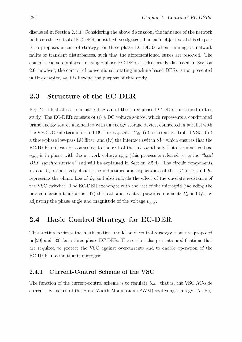
26 Chapter 2. Control of EC-DERs
discussed in Section 2.5.3. Considering the above discussion, the influence of the network
faults on the control of EC-DERs must be investigated. The main objective of this chapter
is to proposes a control strategy for three-phase EC-DERs when running on network
faults or transient disturbances, such that the aforementioned issues are resolved. The
control scheme employed for single-phase EC-DERs is also briefly discussed in Section
2.6; however, the control of conventional rotating-machine-based DERs is not presented
in this chapter, as it is beyond the purpose of this study.
2.3 Structure of the EC-DER
Fig. 2.1 illustrates a schematic diagram of the three-phase EC-DER considered in this
study. The EC-DER consists of (i) a DC voltage source, which represents a conditioned
prime energy source augmented with an energy storage device, connected in parallel with
the VSC DC-side terminals and DC-link capacitor Cdc; (ii) a current-controlled VSC; (iii)
a three-phase low-pass LC filter; and (iv) the interface switch SW which ensures that the
EC-DER unit can be connected to the rest of the microgrid only if its terminal voltage
vsbac is in phase with the network voltage vgabc (this process is referred to as the “local
DER synchronization” and will be explained in Section 2.5.4). The circuit components
Ls and Cs respectively denote the inductance and capacitance of the LC filter, and Rs
represents the ohmic loss of Ls and also embeds the effect of the on-state resistance of
the VSC switches. The EC-DER exchanges with the rest of the microgrid (including the
interconnection transformer Tr) the real- and reactive-power components Ps and Qs, by
adjusting the phase angle and magnitude of the voltage vsabc.
2.4 Basic Control Strategy for EC-DER
This section reviews the mathematical model and control strategy that are proposed
in [20] and [33] for a three-phase EC-DER. The section also presents modifications that
are required to protect the VSC against overcurrents and to enable operation of the
EC-DER in a multi-unit microgrid.
2.4.1 Current-Control Scheme of the VSC
The function of the current-control scheme is to regulate itabc, that is, the VSC AC-side
current, by means of the Pulse-Width Modulation (PWM) switching strategy. As Fig.
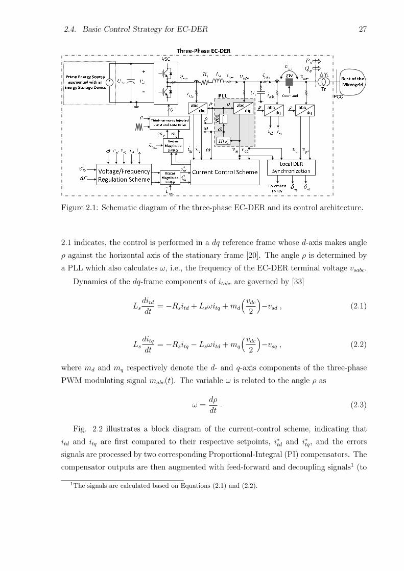
2.4. Basic Control Strategy for EC-DER 27
Figure 2.1: Schematic diagram of the three-phase EC-DER and its control architecture.
2.1 indicates, the control is performed in a dq reference frame whose d-axis makes angle
ρ against the horizontal axis of the stationary frame [20]. The angle ρ is determined by
a PLL which also calculates ω, i.e., the frequency of the EC-DER terminal voltage vsabc.
Dynamics of the dq-frame components of itabc are governed by [33]
Lsditddt
= −Rsitd + Lsωitq +md
(vdc2
)−vsd , (2.1)
Lsditqdt
= −Rsitq − Lsωitd +mq
(vdc2
)−vsq , (2.2)
where md and mq respectively denote the d- and q-axis components of the three-phase
PWM modulating signal mabc(t). The variable ω is related to the angle ρ as
ω =dρ
dt. (2.3)
Fig. 2.2 illustrates a block diagram of the current-control scheme, indicating that
itd and itq are first compared to their respective setpoints, i∗td and i∗tq, and the errors
signals are processed by two corresponding Proportional-Integral (PI) compensators. The
compensator outputs are then augmented with feed-forward and decoupling signals1 (to
1The signals are calculated based on Equations (2.1) and (2.2).
28 Chapter 2. Control of EC-DERs
Figure 2.2: Block diagram of the current-control scheme of the three-phase EC-DER.
mitigate the impact of load voltage variations on the regulation of itd and itq), and the
resulting signals are normalized to the VSC gain vdc/2 and produce md and mq for
the PWM gating pulse generator. Finally, using the angle ρ, the PWM gating pulse
generator transforms md and mq to mabc(t), compares each component of mabc(t) to a
high-frequency carrier signal, and determines the switching instants for each leg of the
converter.
To operate the VSC in its linear modulation region, md and mq are limited by a block
that ensures√m2
d +m2q ≤ mmax, where mmax is the maximum permissible magnitude of
mabc(t); it is unity for the conventional PWM strategy, and 1.15 for PWMwith third-order
harmonic injection [20]. The module, labeled in Figs. 2.1 and 2.2 as the “vector magnitude
limiter”, however, does not change the ratios md/√
m2d +m2
q and mq/√
m2d +m2
q (i.e., it
does not change the phase angle of mabc(t)).
If the PI compensator gains are chosen as
kpi =Ls
τi, (2.4)
and
kii =Rs
τi, (2.5)

2.4. Basic Control Strategy for EC-DER 29
then the closed-loop current-control scheme becomes equivalent to two decoupled first-
order systems described by
Itd(s)
I∗td(s)=
1
τis+ 1, (2.6)
Itq(s)
I∗tq(s)=
1
τis+ 1, (2.7)
in which the design parameter τi turns out to be the time-constant of the closed-loop
step responses. As Fig. 2.1 shows, i∗td and i∗tq are limited by a corresponding vector
magnitude limiter to ensure that√
(i∗td)2 + (i∗tq)
2 ≤ itmax, where itmax is the maximum
permissible magnitude of the VSC AC-side current and is, typically, larger than the VSC
rated current magnitude by about 20 to 50 percent. The process ensures that the VSC is
protected against fault incidents and overload conditions. It is again noted that the vector
magnitude limiter does not change the ratios i∗td/√
(i∗td)2 + (i∗tq)
2 and i∗tq/√(i∗td)
2 + (i∗tq)2
(i.e., does not change the phase angle of i∗tabc(t)).
2.4.2 Voltage Magnitude Regulation Scheme
The objective of the voltage magnitude regulation scheme is to regulate vs, that is, the
magnitude of vsabc(vs =
√v2sd + v2sq
). As will be discussed in Section 2.4.4, the voltage
component vsq is controlled in a scheme that is referred to as the “frequency regulation
scheme”. It will also be discussed that the steady-state value of vsq is zero. Therefore, the
regulation of vs boils effectively down to the regulation of vsd at the magnitude setpoint
v∗sd [33]. In a single-unit microgrid, v∗sd can be assigned a value equivalent to the nominal
magnitude of the network voltage. In a multi-unit system, however, v∗sd is commonly
obtained from the droop characteristic
v∗sd = DQ(Q∗ −Q) + V0 , (2.8)
where Q∗ denotes the setpoint for the reactive-power output of the EC-DER in the grid-
connected mode of operation, and V0 signifies the nominal network voltage magnitude; Q
is the reactive-power output of the EC-DER, and the constant parameter DQ is the droop
coefficient. It should be noted that any exchange of reactive power between the EC-DER
and the network requires a difference between the magnitudes of the DER terminal and
30 Chapter 2. Control of EC-DERs
network voltages. Therefore, based on (2.8), Q tracks Q∗ with some steady-state error,
unless Q∗ is set to zero. The steady-state error can be avoided if v∗sd includes the integral
of the signal Q∗ −Q [31]; however, this option has not been exercised in this thesis.
Dynamics of vsd and vsq are governed by [33]
Csdvsddt
= Csωvsq + itd − isd , (2.9)
Csdvsqdt
= −Csωvsd + itq − isq , (2.10)
which suggest that the DER terminal voltage (i.e., vsd and vsq) can be controlled by the
VSC AC-side current (i.e., itd and itq). Equations (2.9) and (2.10) also indicates that the
DER output current components, that is, isd and isq, are the responses of the rest of the
microgrid to vsd, vsq, and ρ. In general, dynamics of isd and isq are coupled, nonlinear,
time varying, and of a high order. Thus, the control of vsd and vsq is not a straightforward
task, from the controller tuning and stability viewpoints. Hence, measures of isd and isq
should also be included in the control process, as feed-forward signals.
The regulation of vsd and vsq at their respective setpoints is achieved through the
scheme of Fig. 2.3, illustrating that the error signals v∗sd− vsd and v∗sq − vsq are processed
by two corresponding PI compensators and produce the current setpoints i∗td and i∗tq. Fig.
2.3(b) also shows that measures of isd and isq are added as feed-forward signals to the
outputs of the two compensators; the objective is to weaken the dynamic linkage between
the EC-DER and the rest of the microgrid. Fig. 2.3 further shows that the coupling
between vsd and vsq is compensated for, through the inclusion of proper feed-forward
signals. The outcome is that the closed-loop control system is split, approximately, to
two decoupled single-input-single-output control loops, as shown in Figs. 2.4(a) and (b);
the compensator design for the loops of Fig. 2.4 is quite straightforward.
2.4.3 Phase-Locked Loop (PLL)
As indicated in Section 2.4.1, the angle ρ is used for the abc-to-dq frame transformations
and also for the dq-to-abc frame transformation. The angle is calculated by means of a
PLL whose schematic diagram is shown in Fig. 2.5. As indicated in the figure, the PLL
transform vsabc to vsdq and adjusts the rotational speed of the dq-frame, that is, ω, in
such a way that vsq is forced to zero in the steady state [75]. Fig. 2.5 also shows that the
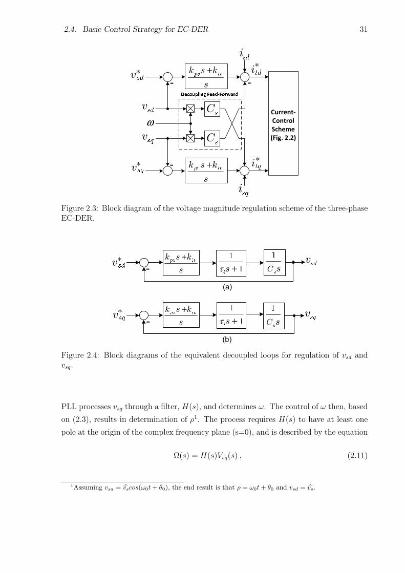
2.4. Basic Control Strategy for EC-DER 31
Figure 2.3: Block diagram of the voltage magnitude regulation scheme of the three-phaseEC-DER.
Figure 2.4: Block diagrams of the equivalent decoupled loops for regulation of vsd andvsq.
PLL processes vsq through a filter, H(s), and determines ω. The control of ω then, based
on (2.3), results in determination of ρ1. The process requires H(s) to have at least one
pole at the origin of the complex frequency plane (s=0), and is described by the equation
Ω(s) = H(s)Vsq(s) , (2.11)
1Assuming vsa = vscos(ω0t+ θ0), the end result is that ρ = ω0t+ θ0 and vsd = vs.
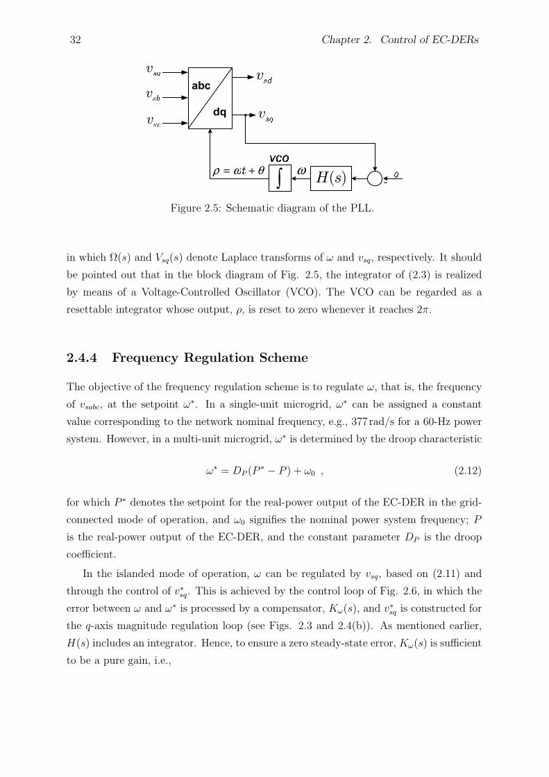
32 Chapter 2. Control of EC-DERs
Figure 2.5: Schematic diagram of the PLL.
in which Ω(s) and Vsq(s) denote Laplace transforms of ω and vsq, respectively. It should
be pointed out that in the block diagram of Fig. 2.5, the integrator of (2.3) is realized
by means of a Voltage-Controlled Oscillator (VCO). The VCO can be regarded as a
resettable integrator whose output, ρ, is reset to zero whenever it reaches 2π.
2.4.4 Frequency Regulation Scheme
The objective of the frequency regulation scheme is to regulate ω, that is, the frequency
of vsabc, at the setpoint ω∗. In a single-unit microgrid, ω∗ can be assigned a constant
value corresponding to the network nominal frequency, e.g., 377rad/s for a 60-Hz power
system. However, in a multi-unit microgrid, ω∗ is determined by the droop characteristic
ω∗ = DP (P∗ − P ) + ω0 , (2.12)
for which P ∗ denotes the setpoint for the real-power output of the EC-DER in the grid-
connected mode of operation, and ω0 signifies the nominal power system frequency; P
is the real-power output of the EC-DER, and the constant parameter DP is the droop
coefficient.
In the islanded mode of operation, ω can be regulated by vsq, based on (2.11) and
through the control of v∗sq. This is achieved by the control loop of Fig. 2.6, in which the
error between ω and ω∗ is processed by a compensator, Kω(s), and v∗sq is constructed for
the q-axis magnitude regulation loop (see Figs. 2.3 and 2.4(b)). As mentioned earlier,
H(s) includes an integrator. Hence, to ensure a zero steady-state error, Kω(s) is sufficient
to be a pure gain, i.e.,
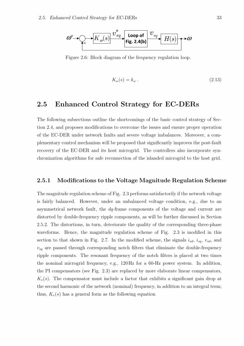
2.5. Enhanced Control Strategy for EC-DERs 33
Figure 2.6: Block diagram of the frequency regulation loop.
Kω(s) = kω . (2.13)
2.5 Enhanced Control Strategy for EC-DERs
The following subsections outline the shortcomings of the basic control strategy of Sec-
tion 2.4, and proposes modifications to overcome the issues and ensure proper operation
of the EC-DER under network faults and severe voltage imbalances. Moreover, a com-
plementary control mechanism will be proposed that significantly improves the post-fault
recovery of the EC-DER and its host microgrid. The controllers also incorporate syn-
chronization algorithms for safe reconnection of the islanded microgrid to the host grid.
2.5.1 Modifications to the Voltage Magnitude Regulation Scheme
The magnitude regulation scheme of Fig. 2.3 performs satisfactorily if the network voltage
is fairly balanced. However, under an unbalanced voltage condition, e.g., due to an
asymmetrical network fault, the dq-frame components of the voltage and current are
distorted by double-frequency ripple components, as will be further discussed in Section
2.5.2. The distortions, in turn, deteriorate the quality of the corresponding three-phase
waveforms. Hence, the magnitude regulation scheme of Fig. 2.3 is modified in this
section to that shown in Fig. 2.7. In the modified scheme, the signals isd, isq, vsd, and
vsq are passed through corresponding notch filters that eliminate the double-frequency
ripple components. The resonant frequency of the notch filters is placed at two times
the nominal microgrid frequency, e.g., 120Hz for a 60-Hz power system. In addition,
the PI compensators (see Fig. 2.3) are replaced by more elaborate linear compensators,
Kv(s). The compensator must include a factor that exhibits a significant gain drop at
the second harmonic of the network (nominal) frequency, in addition to an integral term;
thus, Kv(s) has a general form as the following equation
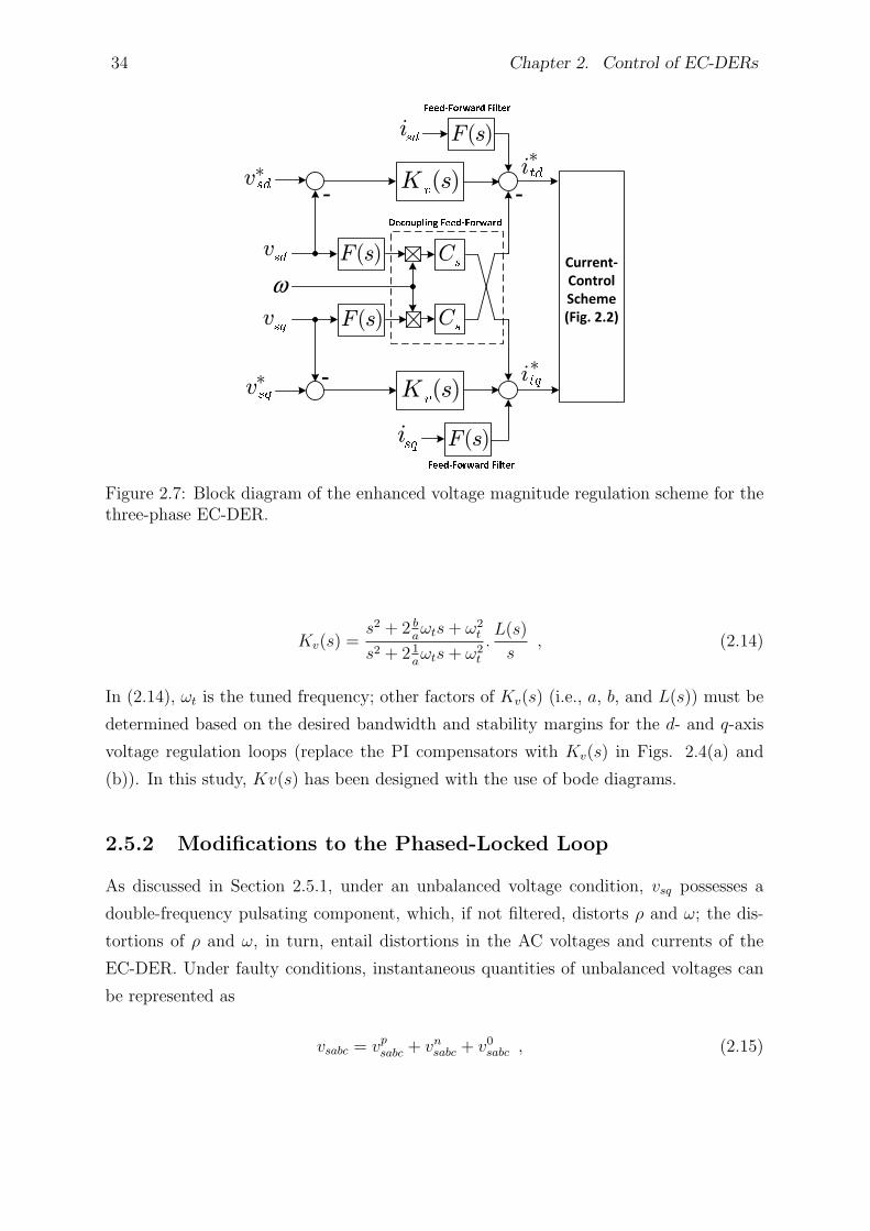
34 Chapter 2. Control of EC-DERs
Figure 2.7: Block diagram of the enhanced voltage magnitude regulation scheme for thethree-phase EC-DER.
Kv(s) =s2 + 2 b
aωts+ ω2
t
s2 + 2 1aωts+ ω2
t
.L(s)
s, (2.14)
In (2.14), ωt is the tuned frequency; other factors of Kv(s) (i.e., a, b, and L(s)) must be
determined based on the desired bandwidth and stability margins for the d- and q-axis
voltage regulation loops (replace the PI compensators with Kv(s) in Figs. 2.4(a) and
(b)). In this study, Kv(s) has been designed with the use of bode diagrams.
2.5.2 Modifications to the Phased-Locked Loop
As discussed in Section 2.5.1, under an unbalanced voltage condition, vsq possesses a
double-frequency pulsating component, which, if not filtered, distorts ρ and ω; the dis-
tortions of ρ and ω, in turn, entail distortions in the AC voltages and currents of the
EC-DER. Under faulty conditions, instantaneous quantities of unbalanced voltages can
be represented as
vsabc = vpsabc + vnsabc + v0sabc , (2.15)
2.5. Enhanced Control Strategy for EC-DERs 35
where subscripts “p”, “n”, and “0” respectively denote positive-, negative-, and zero-
sequence components. Since zero-sequence components of unbalanced voltage sags do
not exist in three-wire systems, nor can they propagate to the secondary side of delta
(or ungrounded star) transformer configurations in four-wire systems, only positive- and
negative-sequence components are considered in this study. Even for unbalanced systems
with zero-sequence voltages, four-leg inverter topologies can eliminate zero-sequence cur-
rents through an appropriate control scheme. Therefore, the matrix form of (2.15) can
be expresses asvsa
vsb
vsc
= Vsp
cos(ωt+ θp)
cos(ωt+ θp − 2π3)
cos(ωt+ θp +2π3)
+ Vsn
cos(ωt+ θn)
cos(ωt+ θn +2π3)
cos(ωt+ θn − 2π3)
, (2.16)
where Vsp and Vsn are the voltage magnitude of the positive- and negative-sequence
voltages, respectively; θp and θn respectively signify the phase angle of the positive- and
negative-sequence voltages. The space-vector equivalent of (2.16) is represented as
−→vs = Vsp ej(ωt+θp) + Vsn e
−j(ωt+θn) , (2.17)
where the space phasor is defined by the generic equation−→f (t) = (2/3)(fa(t)e
j0 +
fb(t)ej2π/3 + fc(t)e
j4π/3) in which fa(t), fb(t), and fc(t) constitute a three-phase signals
or (current/voltage) waveforms. The PLL transforms −→vs to vsdq based on the following
equation [20]
vsdq = vsd + jvsq =−→vs e−jρ , (2.18)
By forcing vsq to zero, the PLL actually attempts to adjust ρ in order to ensure
that ρ = ωt+ θp (assuming that the amplitude of the positive-sequence components are
higher than the negative-sequence ones in normal conditions). Thus, equation (2.18) can
be rewritten as
vsd + jvsq = Vsp + Vsn e−j(2ωt+θn+θp) (2.19)
Equation (2.19) is split into
vsd = Vsp + cos(2ωt+ θn + θp) , (2.20)
36 Chapter 2. Control of EC-DERs
vsq = sin(2ωt+ θn + θp) , (2.21)
The recent equations show that d- and q-axis components of the EC-DER terminal
voltage under faulty conditions include double-frequency harmonics in addition to their
DC components. Thus, transfer function of the PLL, i.e., H(s), cannot be selected as a
simple PI compensator. To filter the pulsating components of vsq, the filter H(s) must
also have the property of exhibiting a low gain at the second harmonic of the power
system (nominal) frequency, that is
H(s) =s2 + 2 b
aωts+ ω2
t
s2 + 2 1aωts+ ω2
t
.T (s)
s, (2.22)
where ωt is the tuned frequency; parameters a and b and the transfer function T (s) are
specified in such a way to fulfill the requirement of the control loop shown in Fig. 2.5.
2.5.3 Proposed Phase-Angle Restoration Scheme
One major issue in a multi-unit microgrid is that, subsequent to a temporary fault, the
EC-DERs do not quickly reclaim their pre-disturbance operating conditions. This is also
the case when the host microgrid undergoes a major transient disturbance, e.g., when
it slides from the islanded mode of operation to the grid-connected mode of operation,
or vice versa. The reason is that major transient incidents often significantly disturb
the magnitude and frequency of the terminal voltages of the EC-DERs (and to a lesser
extent those of rotating-machine-based DERs), and the frequency excursions result in
phase shifts in the DER terminal voltages. By contrast, the frequency setpoints of the
EC-DERs do not deviate much from their pre-disturbance steady-state values as the
droop coefficients are relatively small. The terminal voltage phase shifts can, in turn,
remarkably disturb the real- and reactive-power outputs of the EC-DERs, and may even
lead to system instabilities. As expected, this effect is pronounced more in the islanded
mode of operation.
To mitigate the aforementioned effect, it is proposed that the output of the compen-
sator Kω(s) (see Fig. 2.6) be augmented with an auxiliary signal, uρ, which is obtained
from a mechanism that is illustrated in Fig. 2.8 and referred to as the “phase-angle
restoration scheme”. The function of the phase-angle restoration scheme is to expedite
the post-disturbance recovery of the phase angle of the terminal voltage of the host EC-
DER. As Fig. 2.8 shows, a compensator, Kρ(s), processes the error eρ = ρ∗ − ρ and
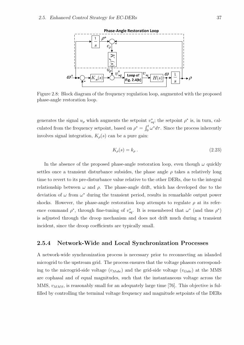
2.5. Enhanced Control Strategy for EC-DERs 37
Figure 2.8: Block diagram of the frequency regulation loop, augmented with the proposedphase-angle restoration loop.
generates the signal uρ which augments the setpoint v∗sq; the setpoint ρ∗ is, in turn, cal-
culated from the frequency setpoint, based on ρ∗ =∫ t
0ω∗dτ . Since the process inherently
involves signal integration, Kρ(s) can be a pure gain:
Kρ(s) = kρ . (2.23)
In the absence of the proposed phase-angle restoration loop, even though ω quickly
settles once a transient disturbance subsides, the phase angle ρ takes a relatively long
time to revert to its pre-disturbance value relative to the other DERs, due to the integral
relationship between ω and ρ. The phase-angle drift, which has developed due to the
deviation of ω from ω∗ during the transient period, results in remarkable output power
shocks. However, the phase-angle restoration loop attempts to regulate ρ at its refer-
ence command ρ∗, through fine-tuning of v∗sq. It is remembered that ω∗ (and thus ρ∗)
is adjusted through the droop mechanism and does not drift much during a transient
incident, since the droop coefficients are typically small.
2.5.4 Network-Wide and Local Synchronization Processes
A network-wide synchronization process is necessary prior to reconnecting an islanded
microgrid to the upstream grid. The process ensures that the voltage phasors correspond-
ing to the microgrid-side voltage (vMabc) and the grid-side voltage (vGabc) at the MMS
are cophasal and of equal magnitudes, such that the instantaneous voltage across the
MMS, vMMS, is reasonably small for an adequately large time [76]. This objective is ful-
filled by controlling the terminal voltage frequency and magnitude setpoints of the DERs
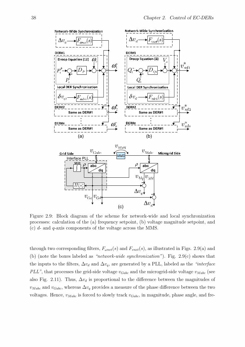
38 Chapter 2. Control of EC-DERs
Figure 2.9: Block diagram of the scheme for network-wide and local synchronizationprocesses: calculation of the (a) frequency setpoint, (b) voltage magnitude setpoint, and(c) d- and q-axis components of the voltage across the MMS.
through two corresponding filters, Fωnet(s) and Fvnet(s), as illustrated in Figs. 2.9(a) and
(b) (note the boxes labeled as “network-wide synchronization”). Fig. 2.9(c) shows that
the inputs to the filters, ∆vd and ∆vq, are generated by a PLL, labeled as the “interface
PLL”, that processes the grid-side voltage vGabc and the microgrid-side voltage vMabc (see
also Fig. 2.11). Thus, ∆vd is proportional to the difference between the magnitudes of
vMabc and vGabc, whereas ∆vq provides a measure of the phase difference between the two
voltages. Hence, vMabc is forced to slowly track vGabc, in magnitude, phase angle, and fre-
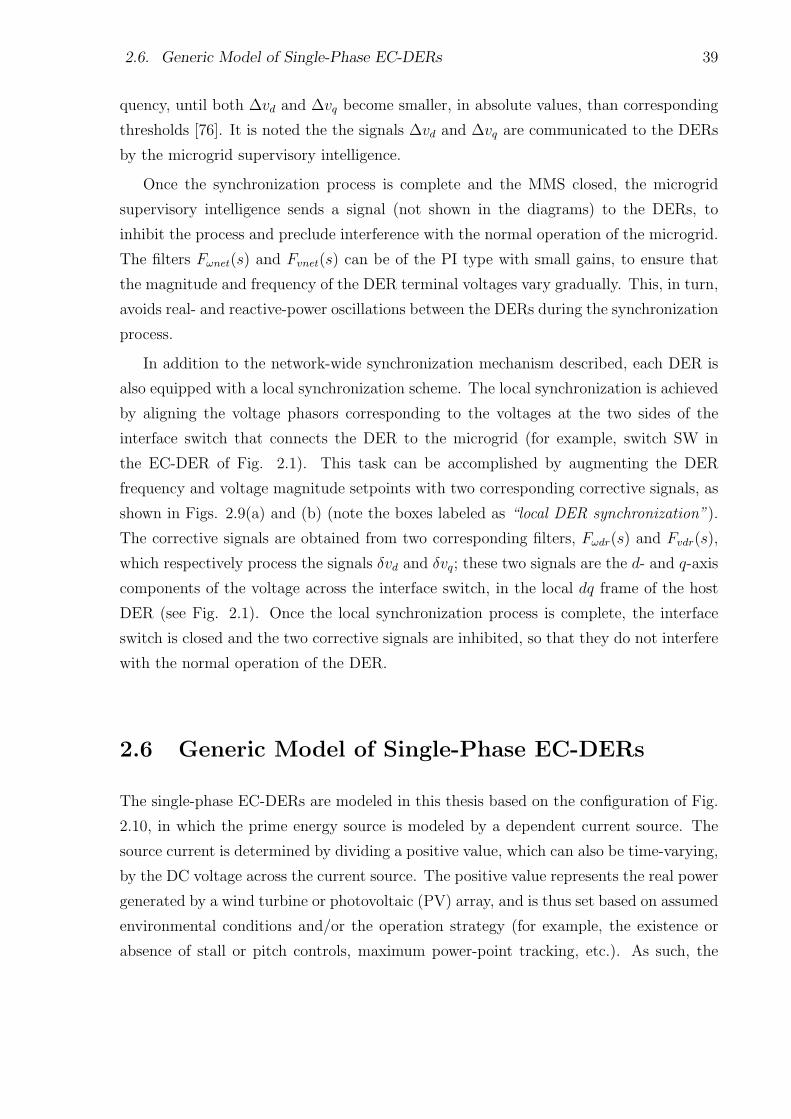
2.6. Generic Model of Single-Phase EC-DERs 39
quency, until both ∆vd and ∆vq become smaller, in absolute values, than corresponding
thresholds [76]. It is noted the the signals ∆vd and ∆vq are communicated to the DERs
by the microgrid supervisory intelligence.
Once the synchronization process is complete and the MMS closed, the microgrid
supervisory intelligence sends a signal (not shown in the diagrams) to the DERs, to
inhibit the process and preclude interference with the normal operation of the microgrid.
The filters Fωnet(s) and Fvnet(s) can be of the PI type with small gains, to ensure that
the magnitude and frequency of the DER terminal voltages vary gradually. This, in turn,
avoids real- and reactive-power oscillations between the DERs during the synchronization
process.
In addition to the network-wide synchronization mechanism described, each DER is
also equipped with a local synchronization scheme. The local synchronization is achieved
by aligning the voltage phasors corresponding to the voltages at the two sides of the
interface switch that connects the DER to the microgrid (for example, switch SW in
the EC-DER of Fig. 2.1). This task can be accomplished by augmenting the DER
frequency and voltage magnitude setpoints with two corresponding corrective signals, as
shown in Figs. 2.9(a) and (b) (note the boxes labeled as “local DER synchronization”).
The corrective signals are obtained from two corresponding filters, Fωdr(s) and Fvdr(s),
which respectively process the signals δvd and δvq; these two signals are the d- and q-axis
components of the voltage across the interface switch, in the local dq frame of the host
DER (see Fig. 2.1). Once the local synchronization process is complete, the interface
switch is closed and the two corrective signals are inhibited, so that they do not interfere
with the normal operation of the DER.
2.6 Generic Model of Single-Phase EC-DERs
The single-phase EC-DERs are modeled in this thesis based on the configuration of Fig.
2.10, in which the prime energy source is modeled by a dependent current source. The
source current is determined by dividing a positive value, which can also be time-varying,
by the DC voltage across the current source. The positive value represents the real power
generated by a wind turbine or photovoltaic (PV) array, and is thus set based on assumed
environmental conditions and/or the operation strategy (for example, the existence or
absence of stall or pitch controls, maximum power-point tracking, etc.). As such, the
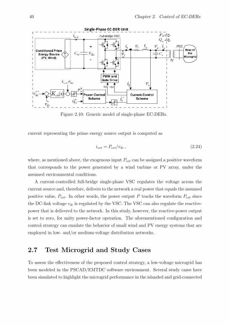
40 Chapter 2. Control of EC-DERs
Figure 2.10: Generic model of single-phase EC-DERs.
current representing the prime energy source output is computed as
iext = Pext/vdc , (2.24)
where, as mentioned above, the exogenous input Pext can be assigned a positive waveform
that corresponds to the power generated by a wind turbine or PV array, under the
assumed environmental conditions.
A current-controlled full-bridge single-phase VSC regulates the voltage across the
current source and, therefore, delivers to the network a real power that equals the assumed
positive value, Pext. In other words, the power output P tracks the waveform Pext since
the DC-link voltage vdc is regulated by the VSC. The VSC can also regulate the reactive-
power that is delivered to the network. In this study, however, the reactive-power output
is set to zero, for unity power-factor operation. The aforementioned configuration and
control strategy can emulate the behavior of small wind and PV energy systems that are
employed in low- and/or medium-voltage distribution networks.
2.7 Test Microgrid and Study Cases
To assess the effectiveness of the proposed control strategy, a low-voltage microgrid has
been modeled in the PSCAD/EMTDC software environment. Several study cases have
been simulated to highlight the microgrid performance in the islanded and grid-connected
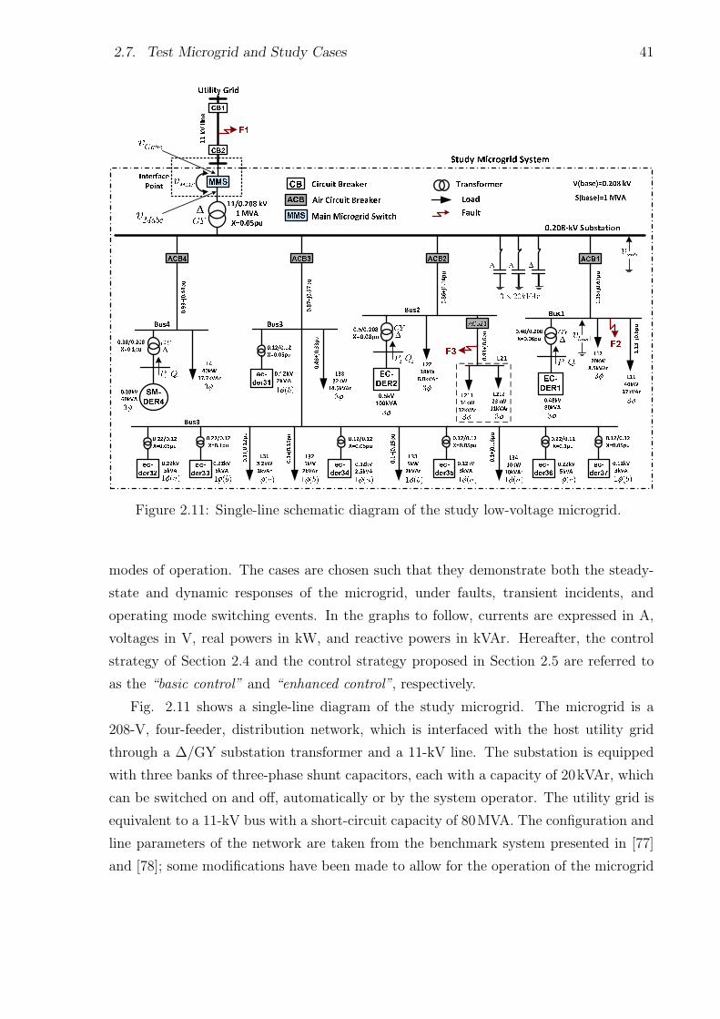
2.7. Test Microgrid and Study Cases 41
Figure 2.11: Single-line schematic diagram of the study low-voltage microgrid.
modes of operation. The cases are chosen such that they demonstrate both the steady-
state and dynamic responses of the microgrid, under faults, transient incidents, and
operating mode switching events. In the graphs to follow, currents are expressed in A,
voltages in V, real powers in kW, and reactive powers in kVAr. Hereafter, the control
strategy of Section 2.4 and the control strategy proposed in Section 2.5 are referred to
as the “basic control” and “enhanced control”, respectively.
Fig. 2.11 shows a single-line diagram of the study microgrid. The microgrid is a
208-V, four-feeder, distribution network, which is interfaced with the host utility grid
through a ∆/GY substation transformer and a 11-kV line. The substation is equipped
with three banks of three-phase shunt capacitors, each with a capacity of 20kVAr, which
can be switched on and off, automatically or by the system operator. The utility grid is
equivalent to a 11-kV bus with a short-circuit capacity of 80MVA. The configuration and
line parameters of the network are taken from the benchmark system presented in [77]
and [78]; some modifications have been made to allow for the operation of the microgrid
42 Chapter 2. Control of EC-DERs
in the islanded mode, in the context of the North American power system.
As Fig. 2.11 shows, a combination of three-phase and single-phase loads are supplied
by the four feeders. The microgrid includes two three-phase EC-DERs, i.e., EC-DER1
and EC-DER2, connected to Bus1 and Bus2, respectively, one synchronous-machine-
based DER, i.e., SM-DER4, connected to Bus4, and seven single-phase EC-DERs, i.e.,
ec-der31 through ec-der37, which are all connected to Bus3. The three-phase DERs are
interfaced with the microgrid through corresponding ∆/GY interconnection transformers,
whereas the single-phase EC-DERs utilize single-phase interconnection transformers.
The two three-phase EC-DERs are droop-controlled, as discussed in Section 2.4, and
represent battery energy storage systems, or represent generators that are augmented
with energy storage, such as fuel-cells augmented with supercapacitors; as such, they
can act as both power sources and sinks. However, SM-DER4 can only source power; it,
for example, represents a biomass-fueled generator. The DER parameters and controller
compensators are given in Appendix A.
The single-phase EC-DERs are also modeled based on the discussion of Section 2.6.
To enable simulation of the cases within manageable CPU times, the VSCs of the EC-
DERs are replaced in the PSCAD models with their averaged-value equivalents [79].
Therefore, switching ripples are absent from the variables. This has allowed us to remove
the filters from the model, with the assumptions of large switching frequency and filter
bandwidths (which is quite achievable).
2.7.1 Grid-Connected Mode of Operation
1) Response to Transient Disturbances: This case demonstrates the effectiveness of
the enhanced control strategy when the microgrid is subjected to a transient disturbance
in the grid-connected mode of operation. Thus, at t = 2.0s, a temporary and bolted
phase-to-ground (AG) fault strikes the 11-kV line at point F1, while the MMS is closed;
the fault lasts for 5.5, 60-Hz cycles.
Figs. 2.12(a) and 2.13(a) represent the system response under the basic control strat-
egy. As Fig. 2.12(a) shows, the voltage waveform of Bus1 becomes severely distorted for
duration of the fault. Moreover, as Fig. 2.13(a) indicates, subsequent to the fault clear-
ance, the real-power outputs of the three-phase EC-DERs do not revert to their respective
pre-disturbance values (the current and reactive-power waveforms exhibit similar quali-
ties, but are not shown due to space limitations). Figs. 2.12(b) and 2.13(b) represent the
system response to the same fault, but when the enhanced control is employed for the
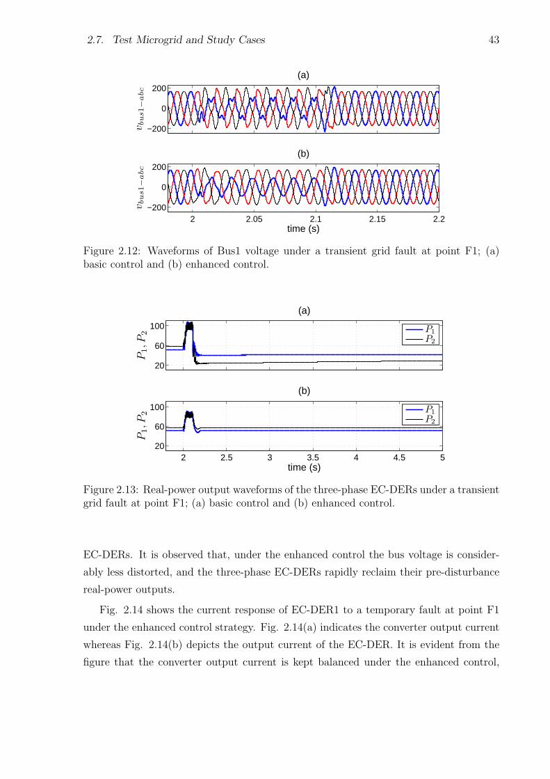
2.7. Test Microgrid and Study Cases 43
−200
0
200
(a)
vbus1−
abc
2 2.05 2.1 2.15 2.2−200
0
200
(b)
vbus1−
abc
time (s)
Figure 2.12: Waveforms of Bus1 voltage under a transient grid fault at point F1; (a)basic control and (b) enhanced control.
20
60
100
P1,P
2
(a)
P1
P2
2 2.5 3 3.5 4 4.5 520
60
100
time (s)
P1,P
2
(b)
P1
P2
Figure 2.13: Real-power output waveforms of the three-phase EC-DERs under a transientgrid fault at point F1; (a) basic control and (b) enhanced control.
EC-DERs. It is observed that, under the enhanced control the bus voltage is consider-
ably less distorted, and the three-phase EC-DERs rapidly reclaim their pre-disturbance
real-power outputs.
Fig. 2.14 shows the current response of EC-DER1 to a temporary fault at point F1
under the enhanced control strategy. Fig. 2.14(a) indicates the converter output current
whereas Fig. 2.14(b) depicts the output current of the EC-DER. It is evident from the
figure that the converter output current is kept balanced under the enhanced control,
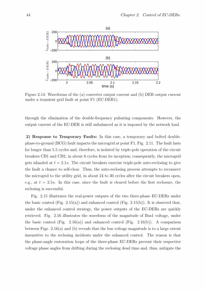
44 Chapter 2. Control of EC-DERs
−200
0
200(a)
itabc−
DE
R1
2 2.05 2.1 2.15 2.2−200
0
200(b)
isabc−
DE
R1
time (s)
Figure 2.14: Waveforms of the (a) converter output current and (b) DER output currentunder a transient grid fault at point F1 (EC-DER1).
through the elimination of the double-frequency pulsating components. However, the
output current of the EC-DER is still unbalanced as it is imposed by the network load.
2) Response to Temporary Faults: In this case, a temporary and bolted double-
phase-to-ground (BCG) fault impacts the microgrid at point F1, Fig. 2.11. The fault lasts
for longer than 5.5 cycles and, therefore, is isolated by triple-pole operation of the circuit
breakers CB1 and CB2, in about 6 cycles from its inception; consequently, the microgrid
gets islanded at t = 2.1s. The circuit breakers exercise triple-pole auto-reclosing to give
the fault a chance to self-clear. Thus, the auto-reclosing process attempts to reconnect
the microgrid to the utility grid, in about 24 to 30 cycles after the circuit breakers open,
e.g., at t = 2.5s. In this case, since the fault is cleared before the first reclosure, the
reclosing is successful.
Fig. 2.15 illustrates the real-power outputs of the two three-phase EC-DERs under
the basic control (Fig. 2.15(a)) and enhanced control (Fig. 2.15(b)). It is observed that,
under the enhanced control strategy, the power outputs of the EC-DERs are quickly
retrieved. Fig. 2.16 illustrates the waveform of the magnitude of Bus1 voltage, under
the basic control (Fig. 2.16(a)) and enhanced control (Fig. 2.16(b)). A comparison
between Figs. 2.16(a) and (b) reveals that the bus voltage magnitude is to a large extent
insensitive to the reclosing incidents under the enhanced control. The reason is that
the phase-angle restoration loops of the three-phase EC-DERs prevent their respective
voltage phase angles from drifting during the reclosing dead time and, thus, mitigate the

2.7. Test Microgrid and Study Cases 45
0
40
80
P1,P
2
(a)
P1
P2
2 2.5 3 3.5 4 4.5 5
0
40
80
time (s)
P1,P
2
(b)
P1
P2
Figure 2.15: Real-power output waveforms of the three-phase EC-DERs during andsubsequent to successful reclosure of the 11-kV line at t=2.5 s; (a) basic control and (b)enhanced control.
0.95
1
1.05
1.1(a)
vbus1
(pu)
2.4 2.45 2.5 2.55 2.6 2.65 2.7 2.75 2.80.95
1
1.05
1.1(b)
vbus1
(pu)
time (s)
Figure 2.16: Waveforms of the magnitude of Bus1 voltage in response to successfulreclosure of the 11-kV line at t=2.5 s; (a) basic control and (b) enhanced control.
impact of out-of-phase reclosing. This is also evident from the waveforms of the voltage
drop across MMS during the reclosing dead time, as shown in Fig. 2.17(a) (basic control)
and Fig. 2.17(b) (enhanced control).
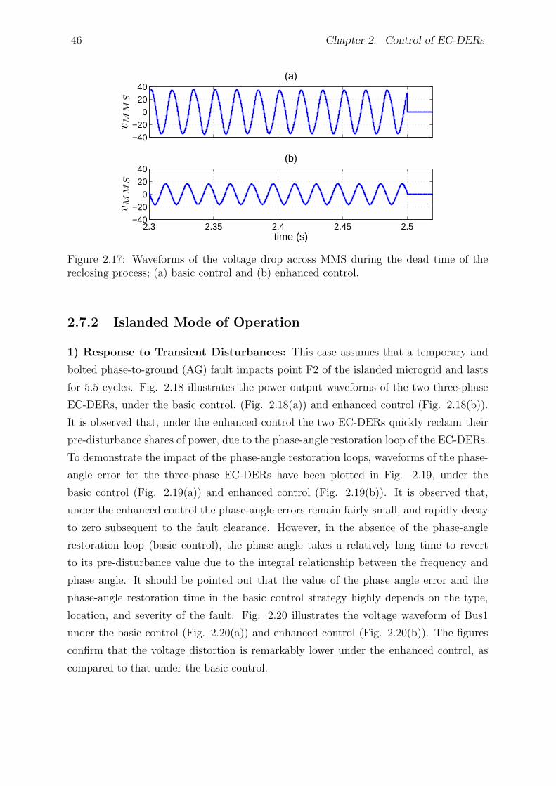
46 Chapter 2. Control of EC-DERs
−40−20
02040
(a)
vM
MS
2.3 2.35 2.4 2.45 2.5−40−20
02040
(b)
vM
MS
time (s)
Figure 2.17: Waveforms of the voltage drop across MMS during the dead time of thereclosing process; (a) basic control and (b) enhanced control.
2.7.2 Islanded Mode of Operation
1) Response to Transient Disturbances: This case assumes that a temporary and
bolted phase-to-ground (AG) fault impacts point F2 of the islanded microgrid and lasts
for 5.5 cycles. Fig. 2.18 illustrates the power output waveforms of the two three-phase
EC-DERs, under the basic control, (Fig. 2.18(a)) and enhanced control (Fig. 2.18(b)).
It is observed that, under the enhanced control the two EC-DERs quickly reclaim their
pre-disturbance shares of power, due to the phase-angle restoration loop of the EC-DERs.
To demonstrate the impact of the phase-angle restoration loops, waveforms of the phase-
angle error for the three-phase EC-DERs have been plotted in Fig. 2.19, under the
basic control (Fig. 2.19(a)) and enhanced control (Fig. 2.19(b)). It is observed that,
under the enhanced control the phase-angle errors remain fairly small, and rapidly decay
to zero subsequent to the fault clearance. However, in the absence of the phase-angle
restoration loop (basic control), the phase angle takes a relatively long time to revert
to its pre-disturbance value due to the integral relationship between the frequency and
phase angle. It should be pointed out that the value of the phase angle error and the
phase-angle restoration time in the basic control strategy highly depends on the type,
location, and severity of the fault. Fig. 2.20 illustrates the voltage waveform of Bus1
under the basic control (Fig. 2.20(a)) and enhanced control (Fig. 2.20(b)). The figures
confirm that the voltage distortion is remarkably lower under the enhanced control, as
compared to that under the basic control.
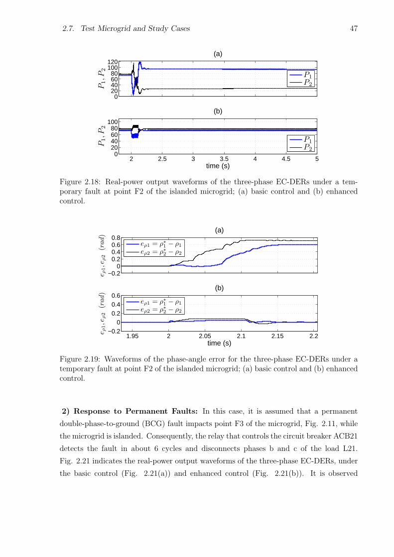
2.7. Test Microgrid and Study Cases 47
020406080
100120
P1,P
2
(a)
P1
P2
2 2.5 3 3.5 4 4.5 50
20406080
100
time (s)
P1,P
2
(b)
P1
P2
Figure 2.18: Real-power output waveforms of the three-phase EC-DERs under a tem-porary fault at point F2 of the islanded microgrid; (a) basic control and (b) enhancedcontrol.
−0.20
0.20.40.60.8
eρ1,e
ρ2
(rad)
(a)
eρ1 = ρ∗1− ρ1
eρ2 = ρ∗2− ρ2
1.95 2 2.05 2.1 2.15 2.2−0.2
00.20.40.6
time (s)
eρ1,e
ρ2
(rad)
(b)
eρ1 = ρ∗1− ρ1
eρ2 = ρ∗2− ρ2
Figure 2.19: Waveforms of the phase-angle error for the three-phase EC-DERs under atemporary fault at point F2 of the islanded microgrid; (a) basic control and (b) enhancedcontrol.
2) Response to Permanent Faults: In this case, it is assumed that a permanent
double-phase-to-ground (BCG) fault impacts point F3 of the microgrid, Fig. 2.11, while
the microgrid is islanded. Consequently, the relay that controls the circuit breaker ACB21
detects the fault in about 6 cycles and disconnects phases b and c of the load L21.
Fig. 2.21 indicates the real-power output waveforms of the three-phase EC-DERs, under
the basic control (Fig. 2.21(a)) and enhanced control (Fig. 2.21(b)). It is observed
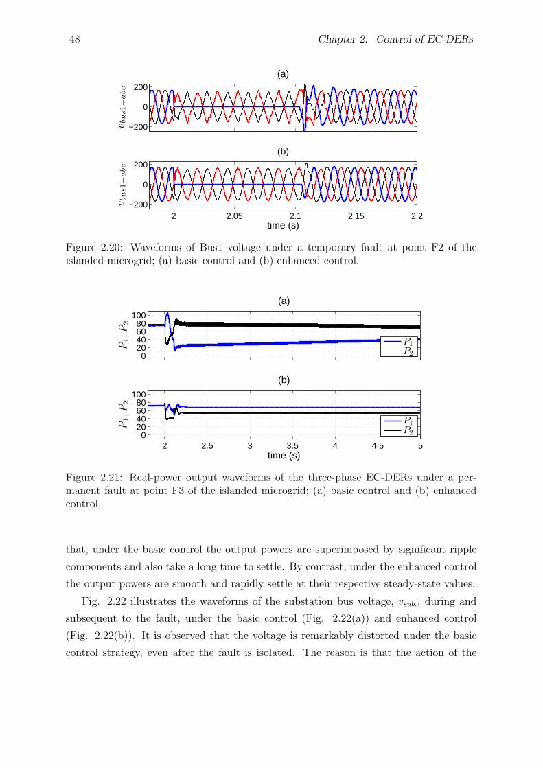
48 Chapter 2. Control of EC-DERs
−200
0
200
(a)
vbus1−
abc
2 2.05 2.1 2.15 2.2−200
0
200
(b)
vbus1−
abc
time (s)
Figure 2.20: Waveforms of Bus1 voltage under a temporary fault at point F2 of theislanded microgrid; (a) basic control and (b) enhanced control.
020406080
100
P1,P
2
(a)
P1
P2
2 2.5 3 3.5 4 4.5 50
20406080
100
time (s)
P1,P
2
(b)
P1
P2
Figure 2.21: Real-power output waveforms of the three-phase EC-DERs under a per-manent fault at point F3 of the islanded microgrid; (a) basic control and (b) enhancedcontrol.
that, under the basic control the output powers are superimposed by significant ripple
components and also take a long time to settle. By contrast, under the enhanced control
the output powers are smooth and rapidly settle at their respective steady-state values.
Fig. 2.22 illustrates the waveforms of the substation bus voltage, vsub., during and
subsequent to the fault, under the basic control (Fig. 2.22(a)) and enhanced control
(Fig. 2.22(b)). It is observed that the voltage is remarkably distorted under the basic
control strategy, even after the fault is isolated. The reason is that the action of the
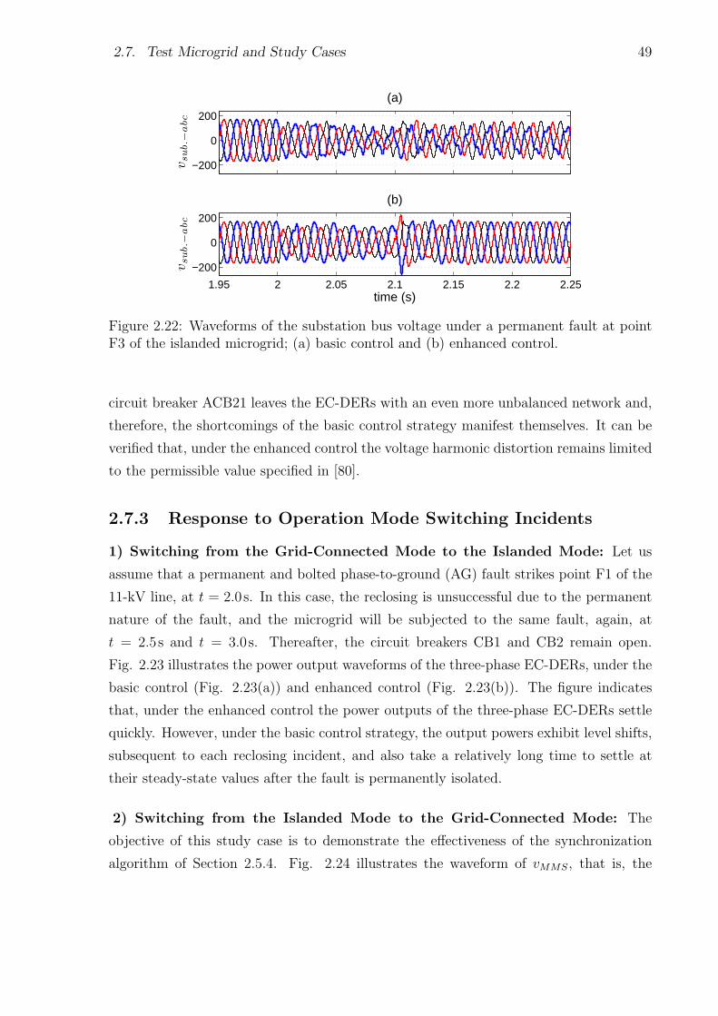
2.7. Test Microgrid and Study Cases 49
−200
0
200
(a)
vsub.−
abc
1.95 2 2.05 2.1 2.15 2.2 2.25
−200
0
200
(b)
vsub.−
abc
time (s)
Figure 2.22: Waveforms of the substation bus voltage under a permanent fault at pointF3 of the islanded microgrid; (a) basic control and (b) enhanced control.
circuit breaker ACB21 leaves the EC-DERs with an even more unbalanced network and,
therefore, the shortcomings of the basic control strategy manifest themselves. It can be
verified that, under the enhanced control the voltage harmonic distortion remains limited
to the permissible value specified in [80].
2.7.3 Response to Operation Mode Switching Incidents
1) Switching from the Grid-Connected Mode to the Islanded Mode: Let us
assume that a permanent and bolted phase-to-ground (AG) fault strikes point F1 of the
11-kV line, at t = 2.0s. In this case, the reclosing is unsuccessful due to the permanent
nature of the fault, and the microgrid will be subjected to the same fault, again, at
t = 2.5s and t = 3.0s. Thereafter, the circuit breakers CB1 and CB2 remain open.
Fig. 2.23 illustrates the power output waveforms of the three-phase EC-DERs, under the
basic control (Fig. 2.23(a)) and enhanced control (Fig. 2.23(b)). The figure indicates
that, under the enhanced control the power outputs of the three-phase EC-DERs settle
quickly. However, under the basic control strategy, the output powers exhibit level shifts,
subsequent to each reclosing incident, and also take a relatively long time to settle at
their steady-state values after the fault is permanently isolated.
2) Switching from the Islanded Mode to the Grid-Connected Mode: The
objective of this study case is to demonstrate the effectiveness of the synchronization
algorithm of Section 2.5.4. Fig. 2.24 illustrates the waveform of vMMS, that is, the
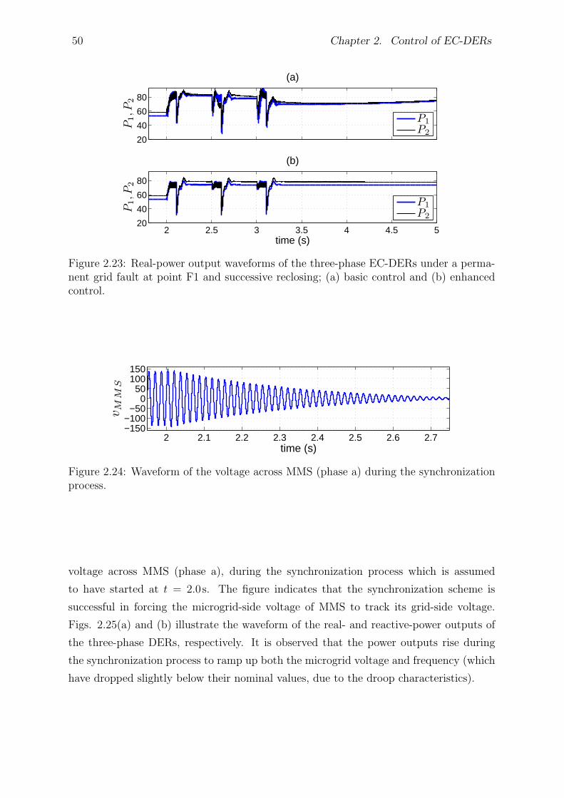
50 Chapter 2. Control of EC-DERs
20
40
60
80
P1,P
2
(a)
P1
P2
2 2.5 3 3.5 4 4.5 520
40
60
80
time (s)
P1,P
2
(b)
P1
P2
Figure 2.23: Real-power output waveforms of the three-phase EC-DERs under a perma-nent grid fault at point F1 and successive reclosing; (a) basic control and (b) enhancedcontrol.
2 2.1 2.2 2.3 2.4 2.5 2.6 2.7−150−100
−500
50100150
vM
MS
time (s)
Figure 2.24: Waveform of the voltage across MMS (phase a) during the synchronizationprocess.
voltage across MMS (phase a), during the synchronization process which is assumed
to have started at t = 2.0s. The figure indicates that the synchronization scheme is
successful in forcing the microgrid-side voltage of MMS to track its grid-side voltage.
Figs. 2.25(a) and (b) illustrate the waveform of the real- and reactive-power outputs of
the three-phase DERs, respectively. It is observed that the power outputs rise during
the synchronization process to ramp up both the microgrid voltage and frequency (which
have dropped slightly below their nominal values, due to the droop characteristics).
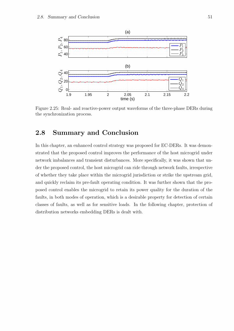
2.8. Summary and Conclusion 51
40
60
80
P1,P
2,P
4
(a)
P1
P2
P4
1.9 1.95 2 2.05 2.1 2.15 2.20
20
40
time (s)
Q1,Q
2,Q
4
(b)
Q1
Q2
Q4
Figure 2.25: Real- and reactive-power output waveforms of the three-phase DERs duringthe synchronization process.
2.8 Summary and Conclusion
In this chapter, an enhanced control strategy was proposed for EC-DERs. It was demon-
strated that the proposed control improves the performance of the host microgrid under
network imbalances and transient disturbances. More specifically, it was shown that un-
der the proposed control, the host microgrid can ride through network faults, irrespective
of whether they take place within the microgrid jurisdiction or strike the upstream grid,
and quickly reclaim its pre-fault operating condition. It was further shown that the pro-
posed control enables the microgrid to retain its power quality for the duration of the
faults, in both modes of operation, which is a desirable property for detection of certain
classes of faults, as well as for sensitive loads. In the following chapter, protection of
distribution networks embedding DERs is dealt with.
Chapter 3
Protection of a Typical Distribution
Network Embedding DERs
3.1 Introduction
The protection issues associated with the introduction of DERs to distribution networks
were discussed in Chapter 1. It was shown that DERs can compromise the protection
coordination amongst the protective devices. Therefore, it is required to retrieve the
protection coordination in the presence of DERs, if possible. This chapter presents the
steps taken to characterize the impact of DERs on the protection coordination, for host
and neighboring feeders, in a typical distribution network. In other words, the chapter
looks into the characterization of protection coordination, in radial distribution systems
embedding DERs, to determine whether or not the coordination is lost subsequent to the
addition of a (new) DER; it is also investigated how the coordination can be resumed if
the DER addition has compromised it.
For the cases that the protection coordination is lost, this chapter proposes a simple
and effective protection strategy that accommodates the effects of DERs in radial dis-
tribution networks. The proposed strategy benefits from microprocessor-based reclosers
and directional elements for feeder relays, and addresses the issues of blinding of protec-
tion, false tripping, recloser-fuse and fuse-fuse miscoordination, and failed auto-reclosing.
In addition, the proposed coordination strategy can be employed for the protection of mi-
crogrids in the grid-connected mode of operation, as will be further discussed in Chapter
4. The effectiveness of the proposed algorithm is demonstrated by digital time-domain
simulation case studies conducted on a model of an example distribution network, in the
52
3.2. Impact of DERs on Traditional Coordination and the Proposed Solution 53
PSCAD/EMTDC software environment.
3.2 Impact of DERs on Traditional Coordination and
the Proposed Solution
Traditional coordination practice of protective devices has been discussed in Section 1.4.1
of the thesis. It is explained that protective devices are coordinated in such a way that
an equal fault current is assumed for all of them; this, however, may not be true in the
presence of DERs. As mentioned in Section 1.4.2, addition of a DER to a feeder, anywhere
downstream of the relay and the recloser, changes Ifmax and Ifmin and also increases the
fuse current as compared to the recloser current [3]. The immediate consequence is that
the coordination will be lost if the fault current exceeds Ifmax, due to the existence of
DERs. The other consequence is that, since as shown in Fig. 1.7 the recloser current
IR becomes less than the fuse current IF , the fuse may melt before the recloser opens in
its fast mode of operation [52]. To accommodate the impact of distributed generation in
the protection coordination, and to overcome the issues mentioned in Section 1.4.2, the
following algorithm is proposed in this chapter.
1. The impact of the DER to be added on the recloser-fuse coordination of the host
feeder or a neighboring feeder is investigated. This is possible based on the approach
introduced in Section 3.3.4. If the coordination remains intact in spite of the
addition of a DER, the algorithm is to be followed from Step 6. Otherwise, the
algorithm is exercised from Step 2.
2. The fault current extremes Ifmin and Ifmax are calculated for the feeder under study;
the former extreme is calculated with no DER considered, whereas the latter one
is calculated for the configuration where all DERs are in place. Such a choice of
Ifmin and Ifmax ensures preservation of the coordination, even if the DERs are
disconnected from the network, for example due to an anti-islanding exercise.
3. The characteristic curves of the devices are coordinated based on the conventional
method explained in Section 1.4.1, which requires the values Ifmin and Ifmax.
4. Since in the presence of DERs the recloser fault current IR is smaller than the fuse
fault current IF , the recloser fast characteristic curve, obtained in Step 3, is revised.
54 Chapter 3. Protection of a Typical Distribution Network Embedding DERs
This requires that the lowest value of IR/IF (less than unity) be calculated, e.g.
using an appropriate phase-sequence equivalent circuit, for the worst-case scenario.
5. The recloser fast characteristic curve is shifted down through its multiplication by
the minimum value of IR/IF . The revised fast characteristic curve is programmed
in the recloser. Thus, the proposed methodology assumes that the recloser is of the
microprocessor-based type and therefore programmable.
6. The impact of the DER on the fuse-fuse coordination of the neighboring feeders is
studied to confirm that the coordination is preserved. The study methodology and
a simple solution for the case where coordination is lost will be introduced in Section
3.3.4, which is based on the slight increase in impedance of the DER interconnection
transformer. It should be emphasized that the fuse-fuse coordination loss is unlikely
to happen in the host feeder. This is due to our assumption that the DERs get
disconnected after the first operation of the recloser and, thus, the coordination
fulfilled as explained above retains its validity.
The algorithm proposed above assumes that a directional relay is employed at the
beginning of the feeders that embed DERs, in order to guarantee that false tripping is
avoided. Moreover, to avoid out-of-phase autoreclosing, it is assumed that the DERs will
be dropped out once the feeder recloser opens the circuit [3], [52]; this is ensured by a
transfer-trip mechanism and/or the anti-islanding schemes incorporated in the individual
DERs, as also identified by the IEEE Std. 1547 [76]. Fig. 3.1 provides a graphical
illustration of the proposed algorithm.
3.3 Design Example
To illustrate its effectiveness, the proposed methodology is applied to, and discussed in
the context of, an example distribution network which, hereinafter, is referred to as the
“test system” in this chapter.
3.3.1 Distribution Network Structure
Fig. 3.2 illustrates a single-line schematic diagram of the test system, which consists of
a 13.8-kV two-feeder distribution subsystem that supplies the loads L1 through L4 via
two feeders, i.e., Feeder 1 and Feeder 2. The subsystem is radially connected to the main
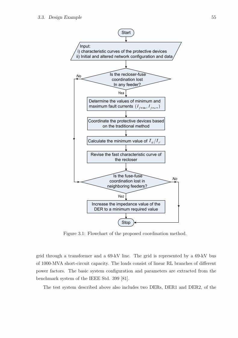
3.3. Design Example 55
Figure 3.1: Flowchart of the proposed coordination method.
grid through a transformer and a 69-kV line. The grid is represented by a 69-kV bus
of 1000-MVA short-circuit capacity. The loads consist of linear RL branches of different
power factors. The basic system configuration and parameters are extracted from the
benchmark system of the IEEE Std. 399 [81].
The test system described above also includes two DERs, DER1 and DER2, of the
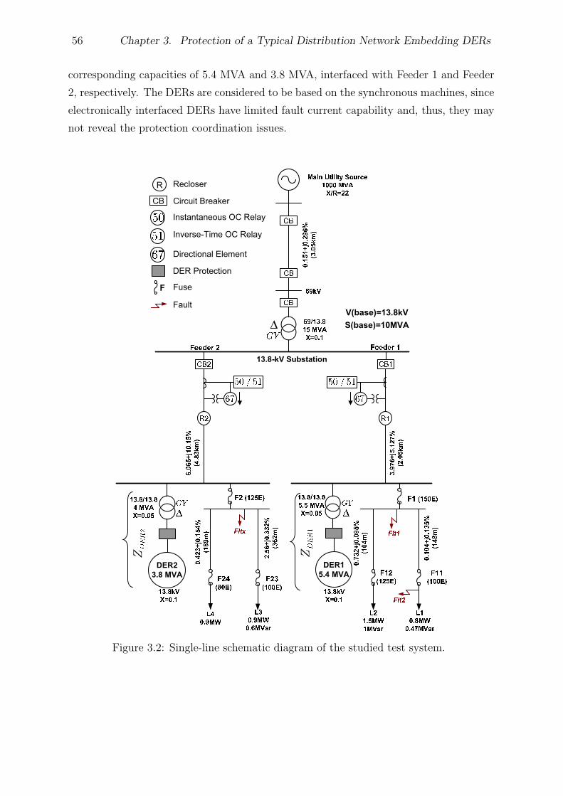
56 Chapter 3. Protection of a Typical Distribution Network Embedding DERs
corresponding capacities of 5.4 MVA and 3.8 MVA, interfaced with Feeder 1 and Feeder
2, respectively. The DERs are considered to be based on the synchronous machines, since
electronically interfaced DERs have limited fault current capability and, thus, they may
not reveal the protection coordination issues.
Figure 3.2: Single-line schematic diagram of the studied test system.
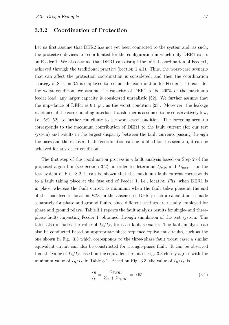
3.3. Design Example 57
3.3.2 Coordination of Protection
Let us first assume that DER2 has not yet been connected to the system and, as such,
the protective devices are coordinated for the configuration in which only DER1 exists
on Feeder 1. We also assume that DER1 can disrupt the initial coordination of Feeder1,
achieved through the traditional practice (Section 1.4.1). Thus, the worst-case scenario
that can affect the protection coordination is considered, and then the coordination
strategy of Section 3.2 is employed to reclaim the coordination for Feeder 1. To consider
the worst condition, we assume the capacity of DER1 to be 200% of the maximum
feeder load; any larger capacity is considered unrealistic [52]. We further assume that
the impedance of DER1 is 0.1 pu, as the worst condition [23]. Moreover, the leakage
reactance of the corresponding interface transformer is assumed to be conservatively low,
i.e., 5% [52], to further contribute to the worst-case condition. The foregoing scenario
corresponds to the maximum contribution of DER1 to the fault current (for our test
system) and results in the largest disparity between the fault currents passing through
the fuses and the recloser. If the coordination can be fulfilled for this scenario, it can be
achieved for any other condition.
The first step of the coordination process is a fault analysis based on Step 2 of the
proposed algorithm (see Section 3.2), in order to determine Ifmin and Ifmax. For the
test system of Fig. 3.2, it can be shown that the maximum fault current corresponds
to a fault taking place at the fuse end of Feeder 1, i.e., location Flt1, when DER1 is
in place, whereas the fault current is minimum when the fault takes place at the end
of the load feeder, location Flt2, in the absence of DER1; such a calculation is made
separately for phase and ground faults, since different settings are usually employed for
phase and ground relays. Table 3.1 reports the fault analysis results for single- and three-
phase faults impacting Feeder 1, obtained through simulation of the test system. The
table also includes the value of IR/IF , for each fault scenario. The fault analysis can
also be conducted based on appropriate phase-sequence equivalent circuits, such as the
one shown in Fig. 3.3 which corresponds to the three-phase fault worst case; a similar
equivalent circuit can also be constructed for a single-phase fault. It can be observed
that the value of IR/IF based on the equivalent circuit of Fig. 3.3 closely agrees with the
minimum value of IR/IF in Table 3.1. Based on Fig. 3.3, the value of IR/IF is
IRIF
=ZDER1
Zth + ZDER1
= 0.65, (3.1)
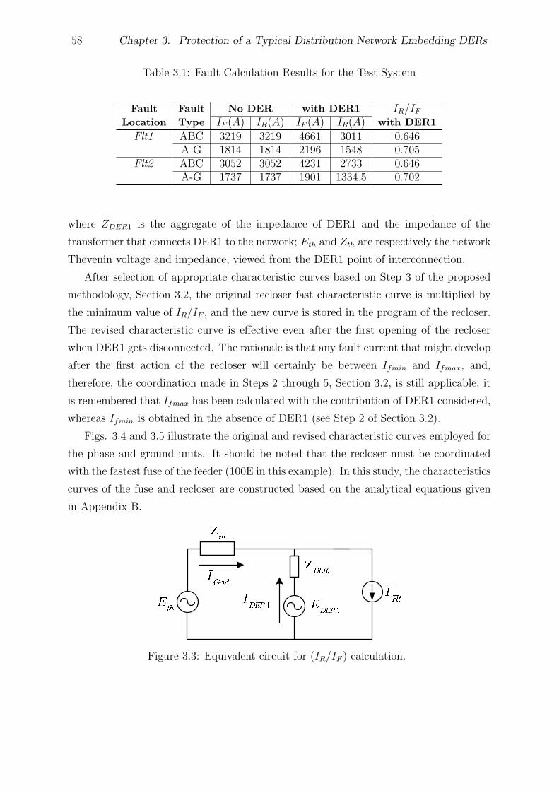
58 Chapter 3. Protection of a Typical Distribution Network Embedding DERs
Table 3.1: Fault Calculation Results for the Test System
Fault Fault No DER with DER1 IR/IFLocation Type IF (A) IR(A) IF (A) IR(A) with DER1
Flt1 ABC 3219 3219 4661 3011 0.646A-G 1814 1814 2196 1548 0.705
Flt2 ABC 3052 3052 4231 2733 0.646A-G 1737 1737 1901 1334.5 0.702
where ZDER1 is the aggregate of the impedance of DER1 and the impedance of the
transformer that connects DER1 to the network; Eth and Zth are respectively the network
Thevenin voltage and impedance, viewed from the DER1 point of interconnection.
After selection of appropriate characteristic curves based on Step 3 of the proposed
methodology, Section 3.2, the original recloser fast characteristic curve is multiplied by
the minimum value of IR/IF , and the new curve is stored in the program of the recloser.
The revised characteristic curve is effective even after the first opening of the recloser
when DER1 gets disconnected. The rationale is that any fault current that might develop
after the first action of the recloser will certainly be between Ifmin and Ifmax, and,
therefore, the coordination made in Steps 2 through 5, Section 3.2, is still applicable; it
is remembered that Ifmax has been calculated with the contribution of DER1 considered,
whereas Ifmin is obtained in the absence of DER1 (see Step 2 of Section 3.2).
Figs. 3.4 and 3.5 illustrate the original and revised characteristic curves employed for
the phase and ground units. It should be noted that the recloser must be coordinated
with the fastest fuse of the feeder (100E in this example). In this study, the characteristics
curves of the fuse and recloser are constructed based on the analytical equations given
in Appendix B.
Figure 3.3: Equivalent circuit for (IR/IF ) calculation.
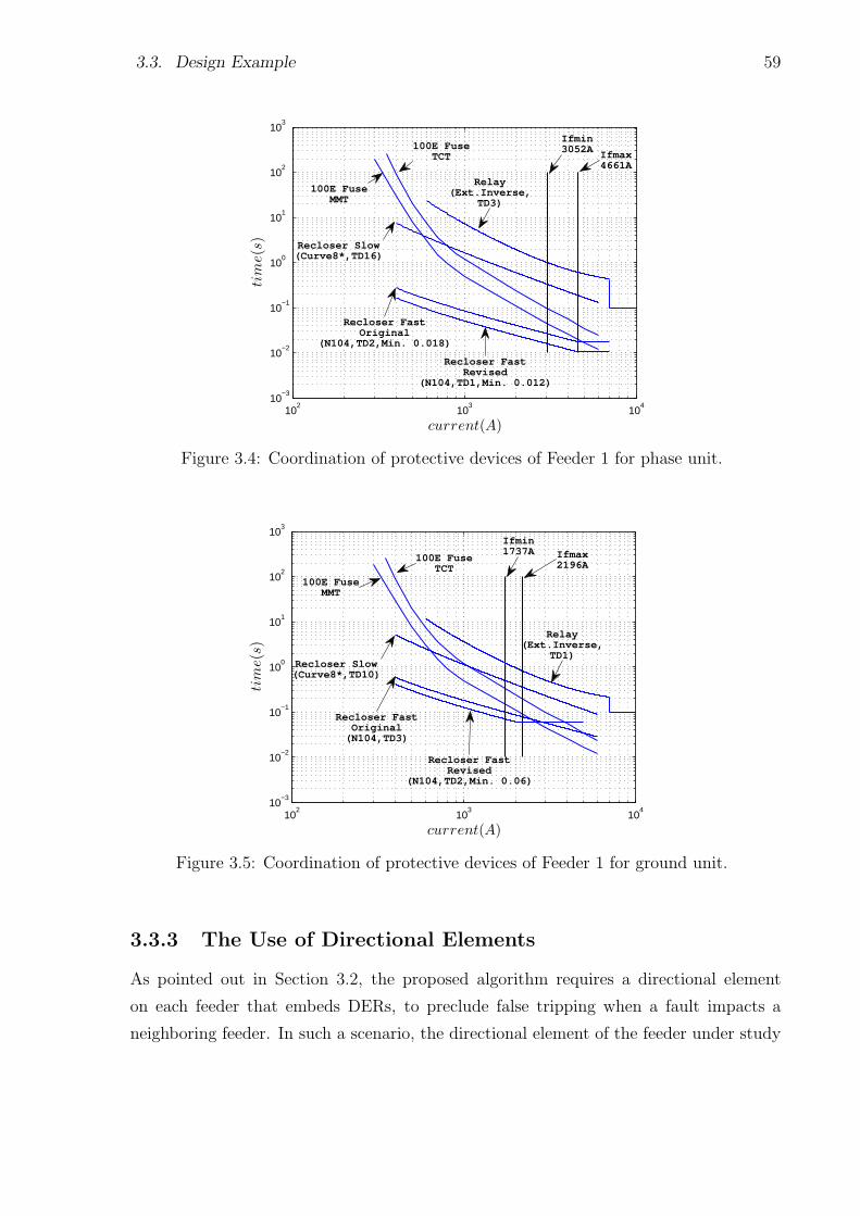
3.3. Design Example 59
102
103
104
10−3
10−2
10−1
100
101
102
103
current(A)
tim
e(s
)
100E FuseTCT
100E FuseMMT
Recloser FastRevised
(N104,TD1,Min. 0.012)
Ifmax4661A
Ifmin3052A
Relay(Ext.Inverse,
TD3)
Recloser FastOriginal
(N104,TD2,Min. 0.018)
Recloser Slow(Curve8*,TD16)
Figure 3.4: Coordination of protective devices of Feeder 1 for phase unit.
102
103
104
10−3
10−2
10−1
100
101
102
103
current(A)
tim
e(s
)
100E FuseTCT
100E FuseMMT
Recloser FastRevised
(N104,TD2,Min. 0.06)
Relay(Ext.Inverse,
TD1)
Ifmax2196A
Ifmin1737A
Recloser Slow(Curve8*,TD10)
Recloser FastOriginal(N104,TD3)
Figure 3.5: Coordination of protective devices of Feeder 1 for ground unit.
3.3.3 The Use of Directional Elements
As pointed out in Section 3.2, the proposed algorithm requires a directional element
on each feeder that embeds DERs, to preclude false tripping when a fault impacts a
neighboring feeder. In such a scenario, the directional element of the feeder under study
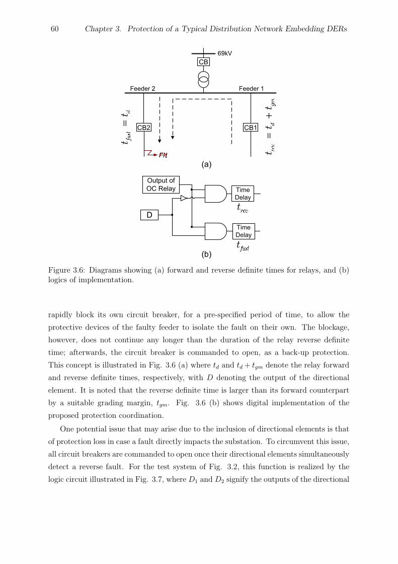
60 Chapter 3. Protection of a Typical Distribution Network Embedding DERs
Figure 3.6: Diagrams showing (a) forward and reverse definite times for relays, and (b)logics of implementation.
rapidly block its own circuit breaker, for a pre-specified period of time, to allow the
protective devices of the faulty feeder to isolate the fault on their own. The blockage,
however, does not continue any longer than the duration of the relay reverse definite
time; afterwards, the circuit breaker is commanded to open, as a back-up protection.
This concept is illustrated in Fig. 3.6 (a) where td and td + tgm denote the relay forward
and reverse definite times, respectively, with D denoting the output of the directional
element. It is noted that the reverse definite time is larger than its forward counterpart
by a suitable grading margin, tgm. Fig. 3.6 (b) shows digital implementation of the
proposed protection coordination.
One potential issue that may arise due to the inclusion of directional elements is that
of protection loss in case a fault directly impacts the substation. To circumvent this issue,
all circuit breakers are commanded to open once their directional elements simultaneously
detect a reverse fault. For the test system of Fig. 3.2, this function is realized by the
logic circuit illustrated in Fig. 3.7, where D1 and D2 signify the outputs of the directional
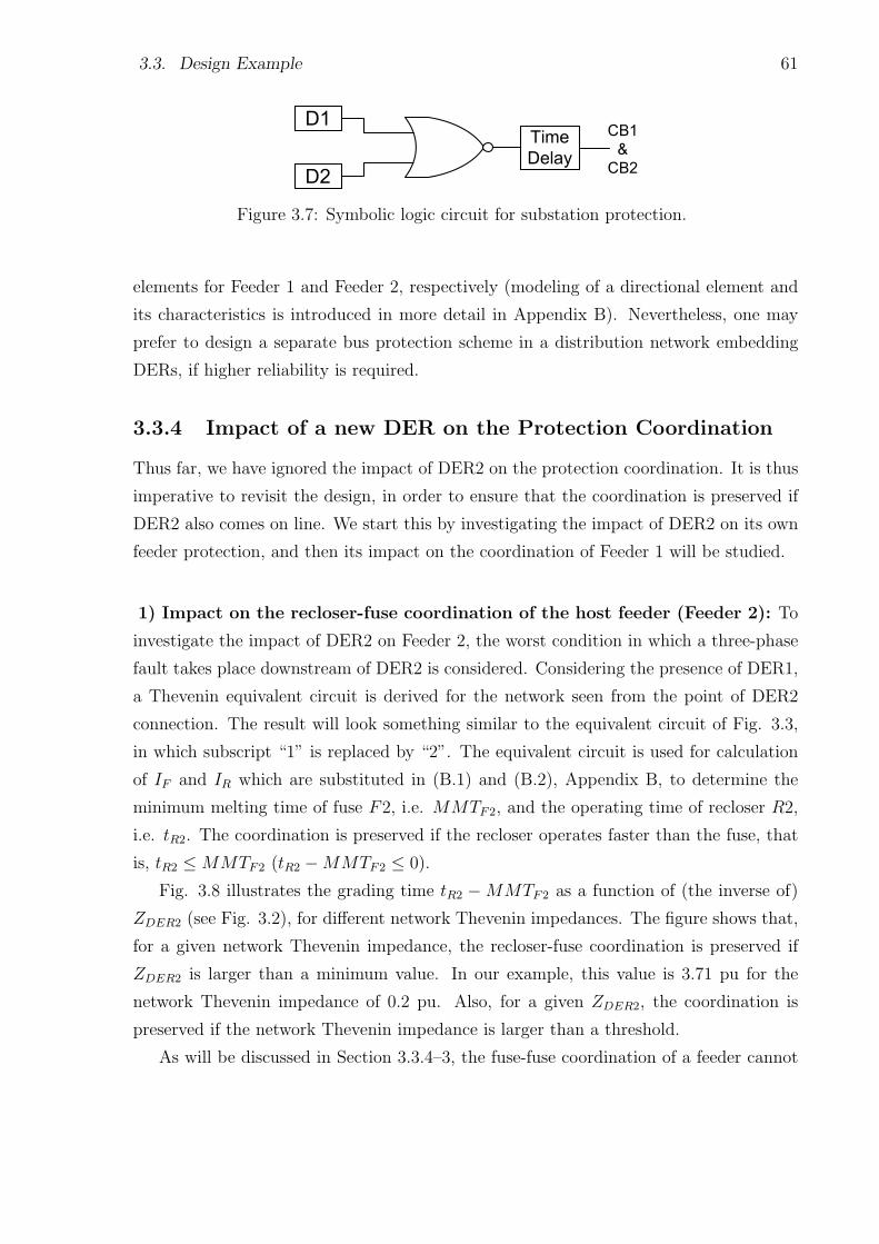
3.3. Design Example 61
Figure 3.7: Symbolic logic circuit for substation protection.
elements for Feeder 1 and Feeder 2, respectively (modeling of a directional element and
its characteristics is introduced in more detail in Appendix B). Nevertheless, one may
prefer to design a separate bus protection scheme in a distribution network embedding
DERs, if higher reliability is required.
3.3.4 Impact of a new DER on the Protection Coordination
Thus far, we have ignored the impact of DER2 on the protection coordination. It is thus
imperative to revisit the design, in order to ensure that the coordination is preserved if
DER2 also comes on line. We start this by investigating the impact of DER2 on its own
feeder protection, and then its impact on the coordination of Feeder 1 will be studied.
1) Impact on the recloser-fuse coordination of the host feeder (Feeder 2): To
investigate the impact of DER2 on Feeder 2, the worst condition in which a three-phase
fault takes place downstream of DER2 is considered. Considering the presence of DER1,
a Thevenin equivalent circuit is derived for the network seen from the point of DER2
connection. The result will look something similar to the equivalent circuit of Fig. 3.3,
in which subscript “1” is replaced by “2”. The equivalent circuit is used for calculation
of IF and IR which are substituted in (B.1) and (B.2), Appendix B, to determine the
minimum melting time of fuse F2, i.e. MMTF2, and the operating time of recloser R2,
i.e. tR2. The coordination is preserved if the recloser operates faster than the fuse, that
is, tR2 ≤ MMTF2 (tR2 −MMTF2 ≤ 0).
Fig. 3.8 illustrates the grading time tR2 −MMTF2 as a function of (the inverse of)
ZDER2 (see Fig. 3.2), for different network Thevenin impedances. The figure shows that,
for a given network Thevenin impedance, the recloser-fuse coordination is preserved if
ZDER2 is larger than a minimum value. In our example, this value is 3.71 pu for the
network Thevenin impedance of 0.2 pu. Also, for a given ZDER2, the coordination is
preserved if the network Thevenin impedance is larger than a threshold.
As will be discussed in Section 3.3.4–3, the fuse-fuse coordination of a feeder cannot
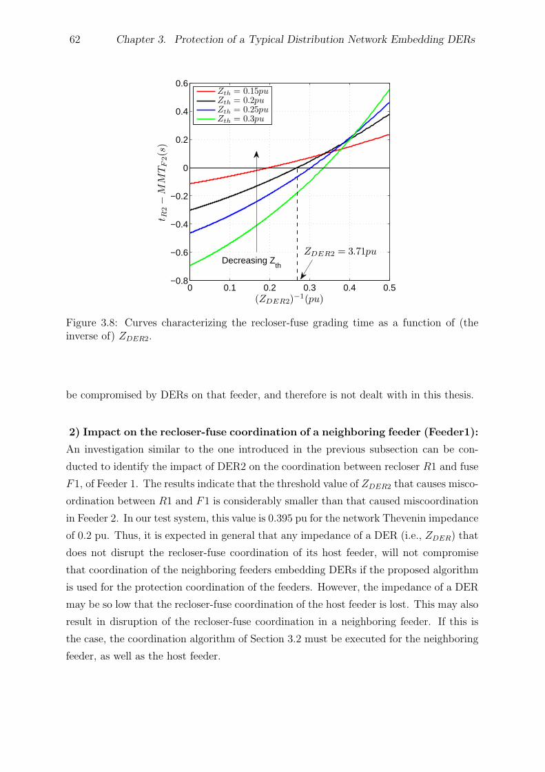
62 Chapter 3. Protection of a Typical Distribution Network Embedding DERs
0 0.1 0.2 0.3 0.4 0.5−0.8
−0.6
−0.4
−0.2
0
0.2
0.4
0.6
(ZDER2)−1(pu)
tR
2−
MM
TF
2(s
)
Decreasing Zth
ZDER2 = 3.71pu
Zth = 0.15pu
Zth = 0.2pu
Zth = 0.25pu
Zth = 0.3pu
Figure 3.8: Curves characterizing the recloser-fuse grading time as a function of (theinverse of) ZDER2.
be compromised by DERs on that feeder, and therefore is not dealt with in this thesis.
2) Impact on the recloser-fuse coordination of a neighboring feeder (Feeder1):
An investigation similar to the one introduced in the previous subsection can be con-
ducted to identify the impact of DER2 on the coordination between recloser R1 and fuse
F1, of Feeder 1. The results indicate that the threshold value of ZDER2 that causes misco-
ordination between R1 and F1 is considerably smaller than that caused miscoordination
in Feeder 2. In our test system, this value is 0.395 pu for the network Thevenin impedance
of 0.2 pu. Thus, it is expected in general that any impedance of a DER (i.e., ZDER) that
does not disrupt the recloser-fuse coordination of its host feeder, will not compromise
that coordination of the neighboring feeders embedding DERs if the proposed algorithm
is used for the protection coordination of the feeders. However, the impedance of a DER
may be so low that the recloser-fuse coordination of the host feeder is lost. This may also
result in disruption of the recloser-fuse coordination in a neighboring feeder. If this is
the case, the coordination algorithm of Section 3.2 must be executed for the neighboring
feeder, as well as the host feeder.

3.3. Design Example 63
3) Impact on the fuse-fuse coordination of a neighboring feeder (Feeder 1):
As pointed out in Section 1.4.2, DERs may compromise fuse-fuse coordinations. Based
on the design procedure of Section 3.2, DERs cannot disrupt the coordinations between
the fuses of their host feeder, since the recloser is supposed to operate first for any fault
impacting the host feeder and, then, the DERs get dropped out. However, DERs may
affect the fuse-fuse coordination of neighboring feeders. For example, if a three-phase
fault impacts branch L2, recloser R1 operates first, and DER1 will be disconnected.
Therefore, DER1 cannot affect the coordination between F1 and F12; however, DER2
is still on line and can disrupt that coordination. This is better shown by Fig. 3.9
where the coordination grading time between F1 and F12, i.e. TCTF12 − MMTF1, is
plotted as a function of (the inverse of) ZDER2, for a three-phase fault (worst condition)
that has taken place at branch L2. Thus, the fuse-fuse coordination is maintained if
the minimum melting time of F1 is less than the total clearing time of F12, that is,
TCTF12−MMTF1 ≤ 0. As Fig. 3.9 indicates, this happens if and only if ZDER2 is larger
than 0.088 pu. It is seen again if ZDER2 can keep coordination between recloser and the
fuse, it will certainly ensure the fuse-fuse coordination for the studied system.
0 5 10 15 20−0.1
−0.08
−0.06
−0.04
−0.02
0
0.02
0.04
(ZDER2)−1(pu)
TC
TF
12−
MM
TF
1(s
)
Decreasing Zth
ZDER2=0.088pu
Zth = 0.15pu
Zth = 0.2pu
Zth = 0.25pu
Zth = 0.3pu
Figure 3.9: Curves characterizing the fuse-fuse grading time as a function of (the inverseof) ZDER2.
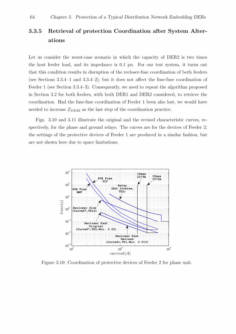
64 Chapter 3. Protection of a Typical Distribution Network Embedding DERs
3.3.5 Retrieval of protection Coordination after System Alter-
ations
Let us consider the worst-case scenario in which the capacity of DER2 is two times
the host feeder load, and its impedance is 0.1 pu. For our test system, it turns out
that this condition results in disruption of the recloser-fuse coordination of both feeders
(see Sections 3.3.4–1 and 3.3.4–2), but it does not affect the fuse-fuse coordination of
Feeder 1 (see Section 3.3.4–3). Consequently, we need to repeat the algorithm proposed
in Section 3.2 for both feeders, with both DER1 and DER2 considered, to retrieve the
coordination. Had the fuse-fuse coordination of Feeder 1 been also lost, we would have
needed to increase ZDER2 as the last step of the coordination practice.
Figs. 3.10 and 3.11 illustrate the original and the revised characteristic curves, re-
spectively, for the phase and ground relays. The curves are for the devices of Feeder 2;
the settings of the protective devices of Feeder 1 are produced in a similar fashion, but
are not shown here due to space limitations.
102
103
104
10−3
10−2
10−1
100
101
102
103
current(A)
tim
e(s
)
Ifmax3570A
Recloser FastRevised
(Curve8+,TD1,Min. 0.013)
Recloser Slow(Curve8*,TD12)
80E FuseTCT
Ifmax2279A
Relay(Ext.Inverse,
TD2)
Recloser FastOriginal
(Curve8*,TD2,Min. 0.02)
80E FuseMMT
Figure 3.10: Coordination of protective devices of Feeder 2 for phase unit.
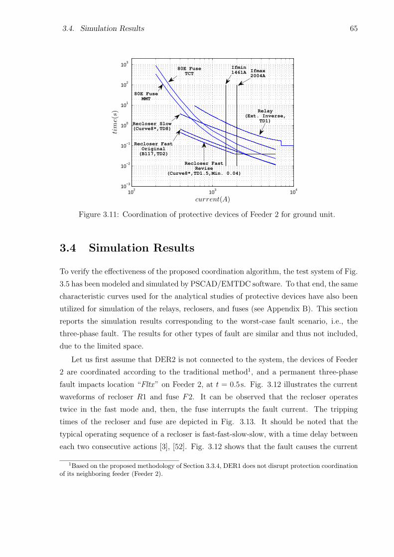
3.4. Simulation Results 65
102
103
104
10−3
10−2
10−1
100
101
102
103
current(A)
tim
e(s
)
80E FuseTCT
Relay(Ext. Inverse,
TD1)
Recloser FastRevise
(Curve8*,TD1.5,Min. 0.04)
Recloser Slow(Curve8*,TD8)
Ifmin1461A Ifmax
2004A
80E FuseMMT
Recloser FastOriginal
(B117,TD2)
Figure 3.11: Coordination of protective devices of Feeder 2 for ground unit.
3.4 Simulation Results
To verify the effectiveness of the proposed coordination algorithm, the test system of Fig.
3.5 has been modeled and simulated by PSCAD/EMTDC software. To that end, the same
characteristic curves used for the analytical studies of protective devices have also been
utilized for simulation of the relays, reclosers, and fuses (see Appendix B). This section
reports the simulation results corresponding to the worst-case fault scenario, i.e., the
three-phase fault. The results for other types of fault are similar and thus not included,
due to the limited space.
Let us first assume that DER2 is not connected to the system, the devices of Feeder
2 are coordinated according to the traditional method1, and a permanent three-phase
fault impacts location “Fltx” on Feeder 2, at t = 0.5s. Fig. 3.12 illustrates the current
waveforms of recloser R1 and fuse F2. It can be observed that the recloser operates
twice in the fast mode and, then, the fuse interrupts the fault current. The tripping
times of the recloser and fuse are depicted in Fig. 3.13. It should be noted that the
typical operating sequence of a recloser is fast-fast-slow-slow, with a time delay between
each two consecutive actions [3], [52]. Fig. 3.12 shows that the fault causes the current
1Based on the proposed methodology of Section 3.3.4, DER1 does not disrupt protection coordinationof its neighboring feeder (Feeder 2).
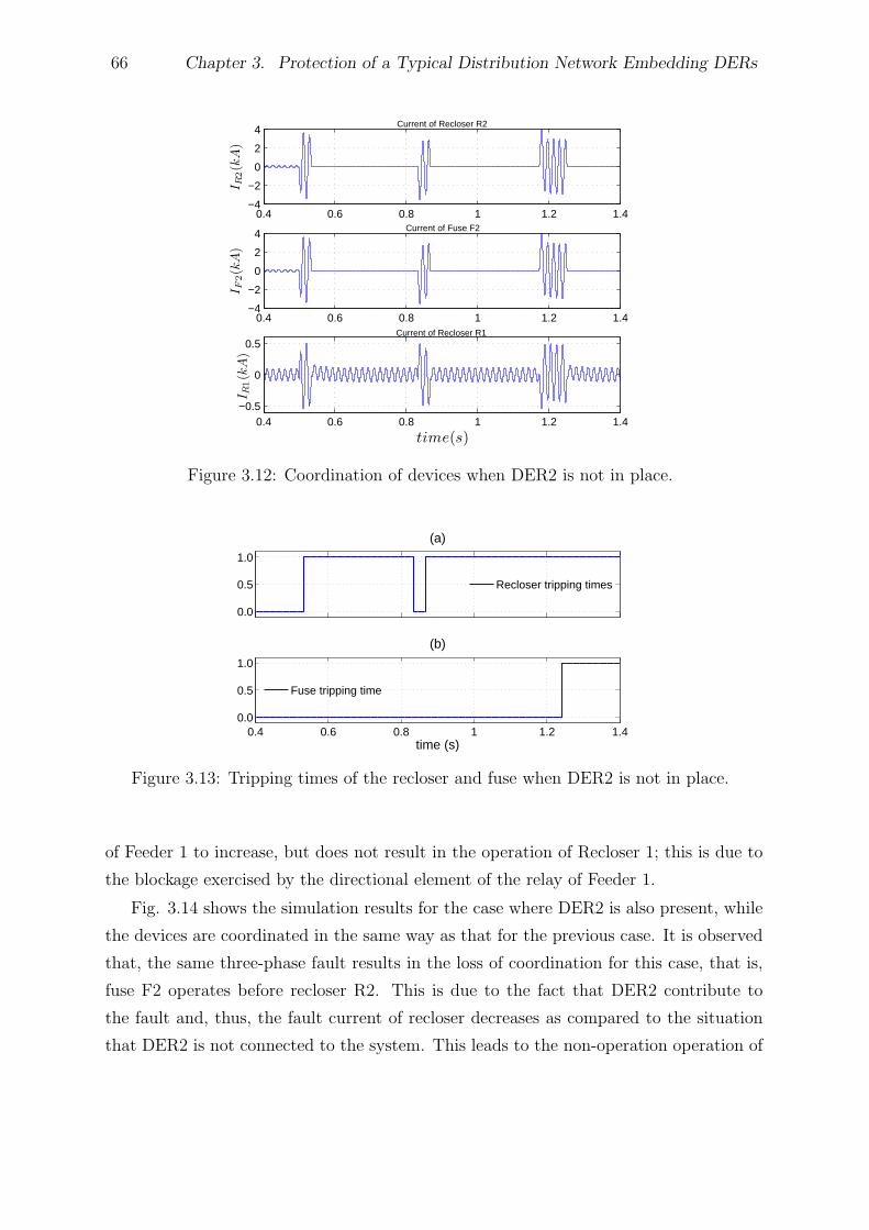
66 Chapter 3. Protection of a Typical Distribution Network Embedding DERs
0.4 0.6 0.8 1 1.2 1.4−4
−2
0
2
4Current of Recloser R2
IR
2(k
A)
0.4 0.6 0.8 1 1.2 1.4−4
−2
0
2
4Current of Fuse F2
IF
2(k
A)
0.4 0.6 0.8 1 1.2 1.4−0.5
0
0.5Current of Recloser R1
IR
1(k
A)
time(s)
Figure 3.12: Coordination of devices when DER2 is not in place.
0.0
0.5
1.0
(a)
Recloser tripping times
0.4 0.6 0.8 1 1.2 1.40.0
0.5
1.0
(b)
time (s)
Fuse tripping time
Figure 3.13: Tripping times of the recloser and fuse when DER2 is not in place.
of Feeder 1 to increase, but does not result in the operation of Recloser 1; this is due to
the blockage exercised by the directional element of the relay of Feeder 1.
Fig. 3.14 shows the simulation results for the case where DER2 is also present, while
the devices are coordinated in the same way as that for the previous case. It is observed
that, the same three-phase fault results in the loss of coordination for this case, that is,
fuse F2 operates before recloser R2. This is due to the fact that DER2 contribute to
the fault and, thus, the fault current of recloser decreases as compared to the situation
that DER2 is not connected to the system. This leads to the non-operation operation of
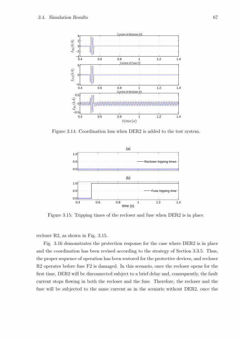
3.4. Simulation Results 67
0.4 0.6 0.8 1 1.2 1.4−4
−2
0
2
4 Current of Recloser R2
IR
2(k
A)
0.4 0.6 0.8 1 1.2 1.4−5
0
5Current of Fuse F2
IF
2(k
A)
0.4 0.6 0.8 1 1.2 1.4−0.5
0
0.5Current of Recloser R1
IR
1(k
A)
time(s)
Figure 3.14: Coordination loss when DER2 is added to the test system.
0.0
0.5
1.0
(a)
Recloser tripping times
0.4 0.6 0.8 1 1.2 1.40.0
0.5
1.0
(b)
time (s)
Fuse tripping time
Figure 3.15: Tripping times of the recloser and fuse when DER2 is in place.
recloser R2, as shown in Fig. 3.15.
Fig. 3.16 demonstrates the protection response for the case where DER2 is in place
and the coordination has been revised according to the strategy of Section 3.3.5. Thus,
the proper sequence of operation has been restored for the protective devices, and recloser
R2 operates before fuse F2 is damaged. In this scenario, once the recloser opens for the
first time, DER2 will be disconnected subject to a brief delay and, consequently, the fault
current stops flowing in both the recloser and the fuse. Therefore, the recloser and the
fuse will be subjected to the same current as in the scenario without DER2, once the
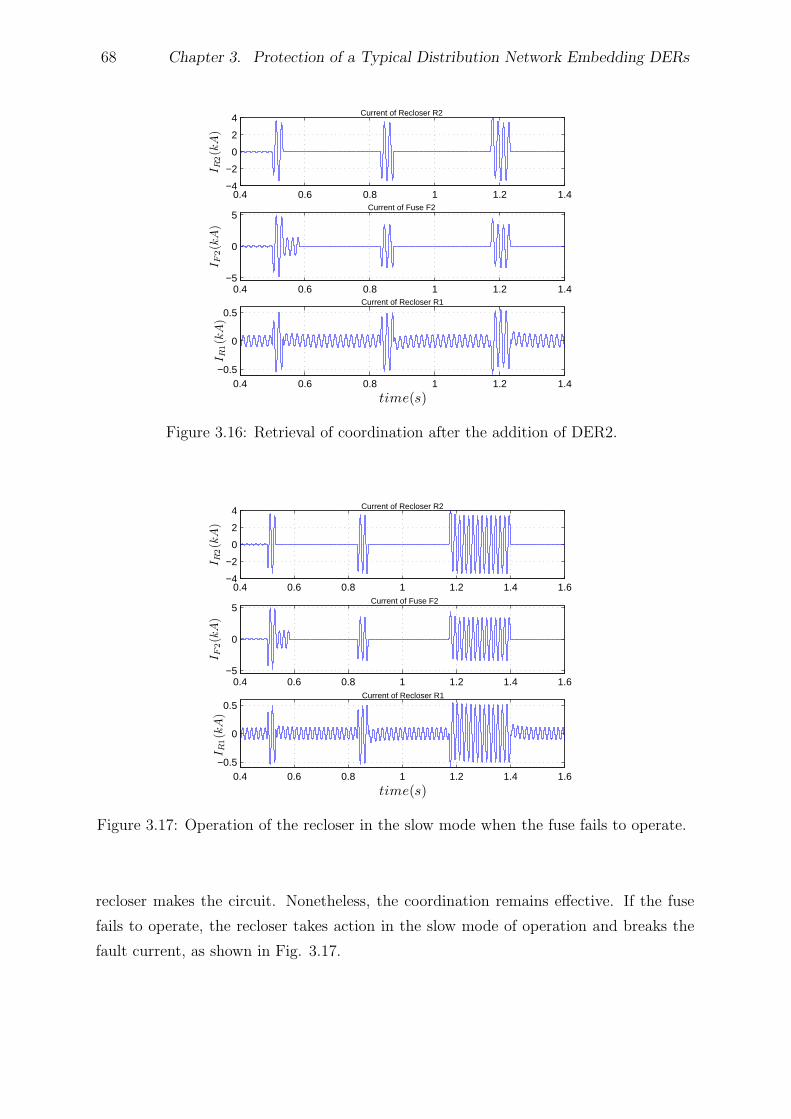
68 Chapter 3. Protection of a Typical Distribution Network Embedding DERs
0.4 0.6 0.8 1 1.2 1.4−4
−2
0
2
4Current of Recloser R2
IR
2(k
A)
0.4 0.6 0.8 1 1.2 1.4−5
0
5Current of Fuse F2
IF
2(k
A)
0.4 0.6 0.8 1 1.2 1.4−0.5
0
0.5Current of Recloser R1
IR
1(k
A)
time(s)
Figure 3.16: Retrieval of coordination after the addition of DER2.
0.4 0.6 0.8 1 1.2 1.4 1.6−4
−2
0
2
4 Current of Recloser R2
IR
2(k
A)
0.4 0.6 0.8 1 1.2 1.4 1.6−5
0
5Current of Fuse F2
IF
2(k
A)
0.4 0.6 0.8 1 1.2 1.4 1.6−0.5
0
0.5Current of Recloser R1
IR
1(k
A)
time(s)
Figure 3.17: Operation of the recloser in the slow mode when the fuse fails to operate.
recloser makes the circuit. Nonetheless, the coordination remains effective. If the fuse
fails to operate, the recloser takes action in the slow mode of operation and breaks the
fault current, as shown in Fig. 3.17.
3.5. Summary and Conclusion 69
3.5 Summary and Conclusion
This chapter investigated the impact of distributed generation on the protection coordina-
tion of radial distribution networks. First, a simple and effective protection strategy was
proposed that provides coordination between protective devices of a radial distribution
system embedding DERs. The proposed strategy benefits from microprocessor-based re-
closers and directional elements for feeder relays, and addresses the main issues associated
with the existence of DERs in distribution networks. Moreover, the proposed strategy
does not require communications or adaptive protective devices. Then, the impact of
future additions of DERs on the coordination was investigated, and the requirements for
preservation of the coordination were identified. It was further discussed in this chapter
that the proposed algorithm could be applied for the worst-case scenario, to reclaim the
coordination in case the requirements are not to be met. The simulation results for a
test system indicated the effectiveness of the method. In the next chapter, protection of
low-voltage/residential microgrids will be discusses.
Chapter 4
Protection of Low-Voltage
Microgrids
4.1 Introduction
As discussed in Chapter 1, microgrids have been proposed as a way of integrating large
numbers of renewable energy resources with distribution systems. The microgrid concept,
however, challenges the operating principals of distribution networks. In particular, one
problem with microgrid implementation is designing a proper protection scheme. It has
been shown that traditional protection schemes does not successfully work for microgrids
and, thus, it is required to have a fresh look into the fundamentals of network protection
such that the safe operation of the microgrids is ensured.
One of the major issues associated with microgrid protection is to devise an appro-
priate protection strategy that is effective in the grid-connected as well as islanded mode
of operation. This chapter proposes a protection strategy for low-voltage microgrids.
Further, the structure of a new relay enabling the proposed protection strategy is pre-
sented. One of the prominent feature of the developed protection scheme is that it does
not require communications or adaptive protective devices. Moreover, it is to a large
extent independent of the fault current magnitude and the mode of operation. Tran-
sient time-domain simulation studies are conducted to demonstrate the effectiveness of
the proposed protection strategy and its enabling relay, using PSCAD/EMTDC software
package.
70
4.2. Characteristics of Low-Voltage Distribution Networks and Assumptions Made 71
4.2 Characteristics of Low-Voltage Distribution Net-
works and Assumptions Made
The following subsections introduce some important characteristics of a Low-Voltage
(LV) distribution network, as they pertain to the operation and protection of a microgrid.
The characteristics will be considered in Sections 4.3 and 4.4, for the development of the
proposed protection strategy.
4.2.1 Structure
An LV microgrid is based on a designated area of a secondary distribution network which
is supplied by a step-down transformer. By assumption, the designated area embeds
sufficient amount of generation and is thus able to operate in isolation from the rest
of the network. The rating of the step-down transformer, which connects the primary
(MV) network to the secondary (LV) network, is typically from a few hundred kVA to
several MVA [77], [78]; hence, the peak power demand of an LV microgrid is assumed to
be limited to a maximum of several MVA. It is further assumed that microgrid loads are
supplied by a number of radial Secondary Mains (SMs), which may be branched by one
or more laterals, and that the presence of single-phase loads and/or DERs makes the LV
microgrid an inherently unbalanced network.
4.2.2 Conventional Protection
In general, simple overcurrent devices, most commonly in the form of fuses, are employed
in secondary distribution networks to protect equipment and ensure safety. Secondary
network conductors are typically protected by the so-called limiters. A limiter is a high-
capacity fuse that is installed on each phase conductor of the SMs at each junction point.
The step-down transformer is protected by a network protector, which is an LV air cir-
cuit breaker with a tripping/closing mechanism controlled by a self-contained relay. In
addition, the network protector has fuses that provide backup protection for the step-
down transformer [86]. Since the fault should rapidly be isolated by the limiters, before
the network protector operates, the time-current characteristics of the limiters must be
coordinated with those of the network protector [86], [87]. This practice ensures that the
smallest possible area of the secondary network is de-energized in response to a fault inci-
dent. The secondary side of the step-down transformer may not necessarily be protected
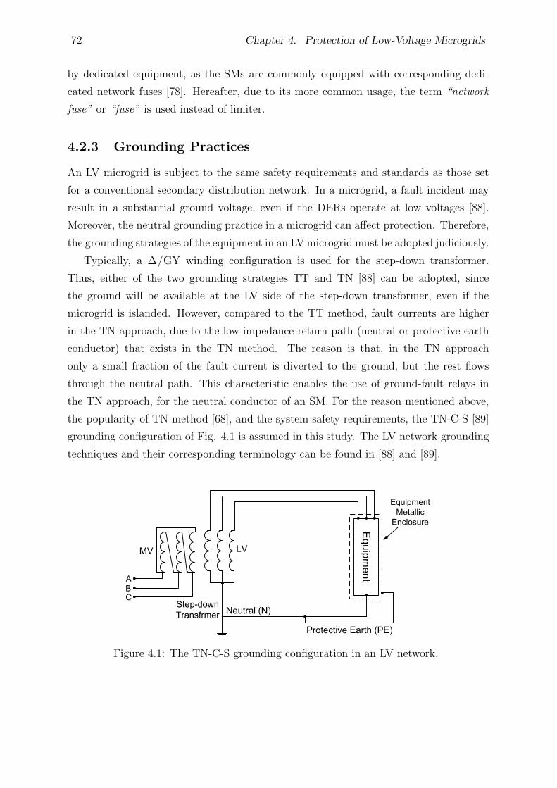
72 Chapter 4. Protection of Low-Voltage Microgrids
by dedicated equipment, as the SMs are commonly equipped with corresponding dedi-
cated network fuses [78]. Hereafter, due to its more common usage, the term “network
fuse” or “fuse” is used instead of limiter.
4.2.3 Grounding Practices
An LV microgrid is subject to the same safety requirements and standards as those set
for a conventional secondary distribution network. In a microgrid, a fault incident may
result in a substantial ground voltage, even if the DERs operate at low voltages [88].
Moreover, the neutral grounding practice in a microgrid can affect protection. Therefore,
the grounding strategies of the equipment in an LVmicrogrid must be adopted judiciously.
Typically, a ∆/GY winding configuration is used for the step-down transformer.
Thus, either of the two grounding strategies TT and TN [88] can be adopted, since
the ground will be available at the LV side of the step-down transformer, even if the
microgrid is islanded. However, compared to the TT method, fault currents are higher
in the TN approach, due to the low-impedance return path (neutral or protective earth
conductor) that exists in the TN method. The reason is that, in the TN approach
only a small fraction of the fault current is diverted to the ground, but the rest flows
through the neutral path. This characteristic enables the use of ground-fault relays in
the TN approach, for the neutral conductor of an SM. For the reason mentioned above,
the popularity of TN method [68], and the system safety requirements, the TN-C-S [89]
grounding configuration of Fig. 4.1 is assumed in this study. The LV network grounding
techniques and their corresponding terminology can be found in [88] and [89].
Figure 4.1: The TN-C-S grounding configuration in an LV network.
4.3. Proposed Protection for the Islanded Mode of Operation 73
4.2.4 DER Interface Mechanisms
The DERs of an LV microgrid can be of the single-phase or three-phase type, based on
rotating machines or interfaced through power-electronic converters of the VSC types.
A single-phase DER is connected between a phase conductor and the neutral conduc-
tor, typically through a single-phase isolation transformer. Thus, the TN-C-S grounding
strategy ensures that the DER can contribute to a phase-to-ground fault current, through
the low-impedance path of the fault current loop. The TN-C-S grounding configuration
can also be adopted for a three-phase DER for which a ∆/GY interconnection trans-
former is employed.
4.2.5 DER Control Strategies
In this chapter, the droop-based voltage/frequency regulation strategy of Section 2.5 has
been employed for the EC-DERs. The conventional rotating-machine-based DERs are
also droop-controlled, that is, the excitation and governor systems of the machine are also
included in their model. The control scheme of each DER embeds a respective synchro-
nization mechanism for safe reconnection of the islanded microgrid to the utility grid.
To ensure that traditional basic protection functions, more specifically the directional
function, can also be employed here, the built-in controls of DERs are designed in such
a way that the DERs behave similarly to the conventional synchronous machines, in the
sense that they more or less maintain the balance of their terminal voltages when an
asymmetrical fault strikes the network; in an EC-DER, of course, the magnitude of the
terminal voltage drops to limit the fault current contribution (see Sections 2.4 and 2.5).
4.3 Proposed Protection for the Islanded Mode of
Operation
4.3.1 Household Consumer Protection
Traditionally, household consumers are protected by small fuses or miniature circuit
breakers. Commonly, the devices are of 6-A, 16-A, and 32-A current ratings, for a 208-V
network [90], and there is no need to replace them. The reason is that the fault current
contributed by the DERs is expected to be sufficiently large to force the fuses to act in
about 5 cycles from the fault inception, even in the islanded mode of operation [90], [91].
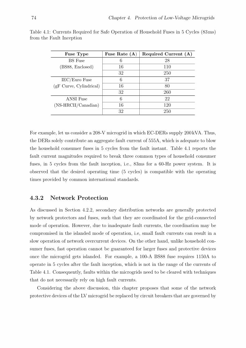
74 Chapter 4. Protection of Low-Voltage Microgrids
Table 4.1: Currents Required for Safe Operation of Household Fuses in 5 Cycles (83ms)from the Fault Inception
Fuse Type Fuse Rate (A) Required Current (A)
BS Fuse 6 28
(BS88, Enclosed) 16 110
32 250
IEC/Euro Fuse 6 37
(gF Curve, Cylindrical) 16 80
32 260
ANSI Fuse 6 22
(NS-HRCII/Canadian) 16 120
32 250
For example, let us consider a 208-V microgrid in which EC-DERs supply 200kVA. Thus,
the DERs solely contribute an aggregate fault current of 555A, which is adequate to blow
the household consumer fuses in 5 cycles from the fault instant. Table 4.1 reports the
fault current magnitudes required to break three common types of household consumer
fuses, in 5 cycles from the fault inception, i.e., 83ms for a 60-Hz power system. It is
observed that the desired operating time (5 cycles) is compatible with the operating
times provided by common international standards.
4.3.2 Network Protection
As discussed in Section 4.2.2, secondary distribution networks are generally protected
by network protectors and fuses, such that they are coordinated for the grid-connected
mode of operation. However, due to inadequate fault currents, the coordination may be
compromised in the islanded mode of operation, i.e, small fault currents can result in a
slow operation of network overcurrent devices. On the other hand, unlike household con-
sumer fuses, fast operation cannot be guaranteed for larger fuses and protective devices
once the microgrid gets islanded. For example, a 100-A BS88 fuse requires 1150A to
operate in 5 cycles after the fault inception, which is not in the range of the currents of
Table 4.1. Consequently, faults within the microgrids need to be cleared with techniques
that do not necessarily rely on high fault currents.
Considering the above discussion, this chapter proposes that some of the network
protective devices of the LV microgrid be replaced by circuit breakers that are governed by
4.3. Proposed Protection for the Islanded Mode of Operation 75
a suitable relaying scheme; replacement of all protective devices by circuit-breakers/relays
is costly and time-consuming. Thus, it is proposed to replace by a relay the network
protector that is located at the microgrid interface point, i.e., where the microgrid is
interfaced with the utility grid. Moreover, the chapter proposes to replace by relays the
fuses that are located at the beginning of the SMs, but to maintain all other network
fuses; the remaining fuses and the added relays shall be coordinated for the grid-connected
mode of operation; this is discussed in Section 4.4. As mentioned, each circuit breaker is
controlled by a corresponding microprocessor-based relay which, hereafter, is referred to
as the “Microgrid Protection Relay” (MPR). The relay that is installed at the microgrid
interface point, is referred to as the “Interface Microgrid Protection Relay” (IMPR). The
introduction of those relays provides an acceptable system reliability for the host LV
microgrid; however, if the same number of isolation points as those possible in the grid-
connected mode were required, more fuses should be replaced by circuit-breakers/relays.
Section 4.3.5 deals with such a scenario.
It is further proposed in this chapter that the circuit breakers installed at the begin-
ning of the SMs have the single-phase tripping capability, to only isolate the smallest
possible part of the network. By contrast, the circuit breaker located at the microgrid
interface point is intended for three-phase tripping. Additionally, it is assumed that each
DER is dropped out if the network frequency and/or voltage are not within their per-
missable ranges, for a prespecified period of time. This is ensured by the corresponding
anti-islanding mechanism which intervenes and disconnects a DER, e.g., through over-
/under-voltage and/or over-/under-frequency relays, as required by IEEE Std. 1547 [76].
4.3.3 Fault Detection
1) Solid Faults: Solid faults are those that do not have a significant fault impedance1.
A solid fault within an islanded microgrid results in a network-wide voltage drop, which
can be utilized for fault detection. In addition, an instantaneous overcurrent relay, which
is set based on the thermal properties of the conductors, can provide a preliminary
redundant protection for solid faults, despite the fact that the fault current may not be
large in the islanded mode of operation.
2) Medium-Impedance Faults: For a medium-impedance fault, neither the voltage
drop nor the fault current may be large. Consequently, the protection scheme may not be
1In some papers, solid faults are also referred to as the “bolted faults”.
76 Chapter 4. Protection of Low-Voltage Microgrids
able to distinguish a faulty condition from a network overload condition. Therefore, this
chapter proposes an additional fault detection strategy that serves as a main redundant
mechanism should the protection functions mentioned in Section 4.3.3–1 fail to operate.
It is proposed to extract the zero- and negative-sequence components of the currents,
and to utilize them as a redundant fault detection mechanism. Thus, if the sequence
components exceed their respective thresholds for a certain time period, an algorithm
issues a trip command. To circumvent false detection due to network voltage and/or
current imbalance, the trip thresholds should be selected judiciously. As discussed in
Section 4.2.5, it is assumed that appropriate voltage regulation strategies are employed
by the DERs such that the network voltage imbalance is maintained down to the standard
limits (i.e., less than 2%) [92]; in this study, a 1.5% voltage imbalance and a 25% load
imbalance have been assumed. The trip thresholds employed in this chapter are specified
in Appendix C.
3) High-Impedance Faults: A reliable protection scheme must also be able to detect
High-Impedance Faults (HIFs), which may have current magnitudes similar to those of
normal loads and therefore not cause any noticeable voltage drop. Even ground-fault
relays may not be able to detect HIFs, especially in systems with multiple grounded
points where the earth return current can take various paths. Almost all of the methods
proposed for HIF detection rely on extracting HIF current waveform characteristics,
such as the energy level [93], high frequency components [94], and harmonic content [95].
This chapter adopts the method proposed in [93] for the HIF detection module that is
incorporated in the MPRs.
4.3.4 Protection Coordination
1) Grading: In an islanded microgrid, the voltage drop caused by a fault appears more
or less across the entire network, due to the limited geographical span. Therefore, it is
almost impossible to coordinate protective devices based on the voltage profile. To ensure
coordination, this chapter proposes the use of a directional element, in conjunction with
fault detection modules. The combination of a fault detection module and a directional
element, with proper definite time delays for forward and reverse faults, can offer an
acceptable protection coordination.
Since no damaging large fault current is expected to exist in the islanded mode of
operation, a definite-time grading technique, starting at the load side of an SM and end-
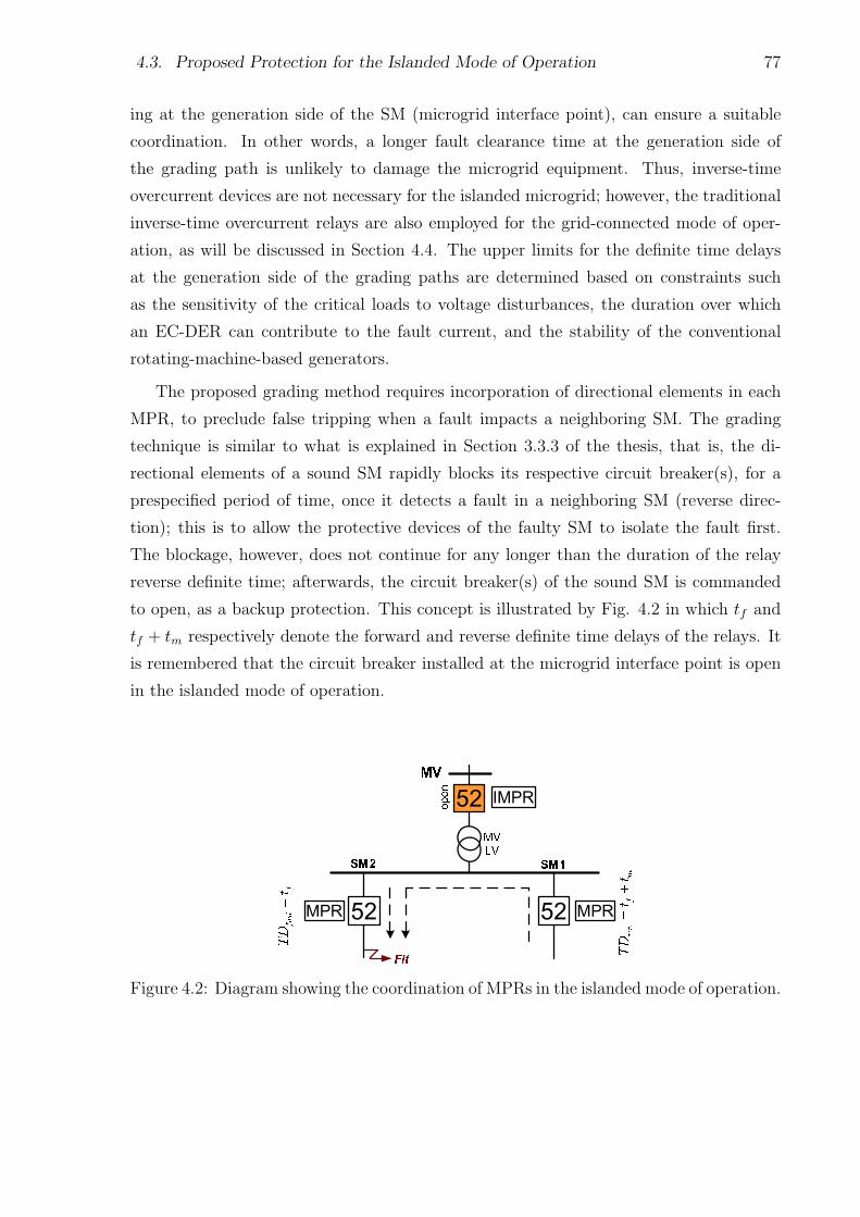
4.3. Proposed Protection for the Islanded Mode of Operation 77
ing at the generation side of the SM (microgrid interface point), can ensure a suitable
coordination. In other words, a longer fault clearance time at the generation side of
the grading path is unlikely to damage the microgrid equipment. Thus, inverse-time
overcurrent devices are not necessary for the islanded microgrid; however, the traditional
inverse-time overcurrent relays are also employed for the grid-connected mode of oper-
ation, as will be discussed in Section 4.4. The upper limits for the definite time delays
at the generation side of the grading paths are determined based on constraints such
as the sensitivity of the critical loads to voltage disturbances, the duration over which
an EC-DER can contribute to the fault current, and the stability of the conventional
rotating-machine-based generators.
The proposed grading method requires incorporation of directional elements in each
MPR, to preclude false tripping when a fault impacts a neighboring SM. The grading
technique is similar to what is explained in Section 3.3.3 of the thesis, that is, the di-
rectional elements of a sound SM rapidly blocks its respective circuit breaker(s), for a
prespecified period of time, once it detects a fault in a neighboring SM (reverse direc-
tion); this is to allow the protective devices of the faulty SM to isolate the fault first.
The blockage, however, does not continue for any longer than the duration of the relay
reverse definite time; afterwards, the circuit breaker(s) of the sound SM is commanded
to open, as a backup protection. This concept is illustrated by Fig. 4.2 in which tf and
tf + tm respectively denote the forward and reverse definite time delays of the relays. It
is remembered that the circuit breaker installed at the microgrid interface point is open
in the islanded mode of operation.
Figure 4.2: Diagram showing the coordination of MPRs in the islanded mode of operation.
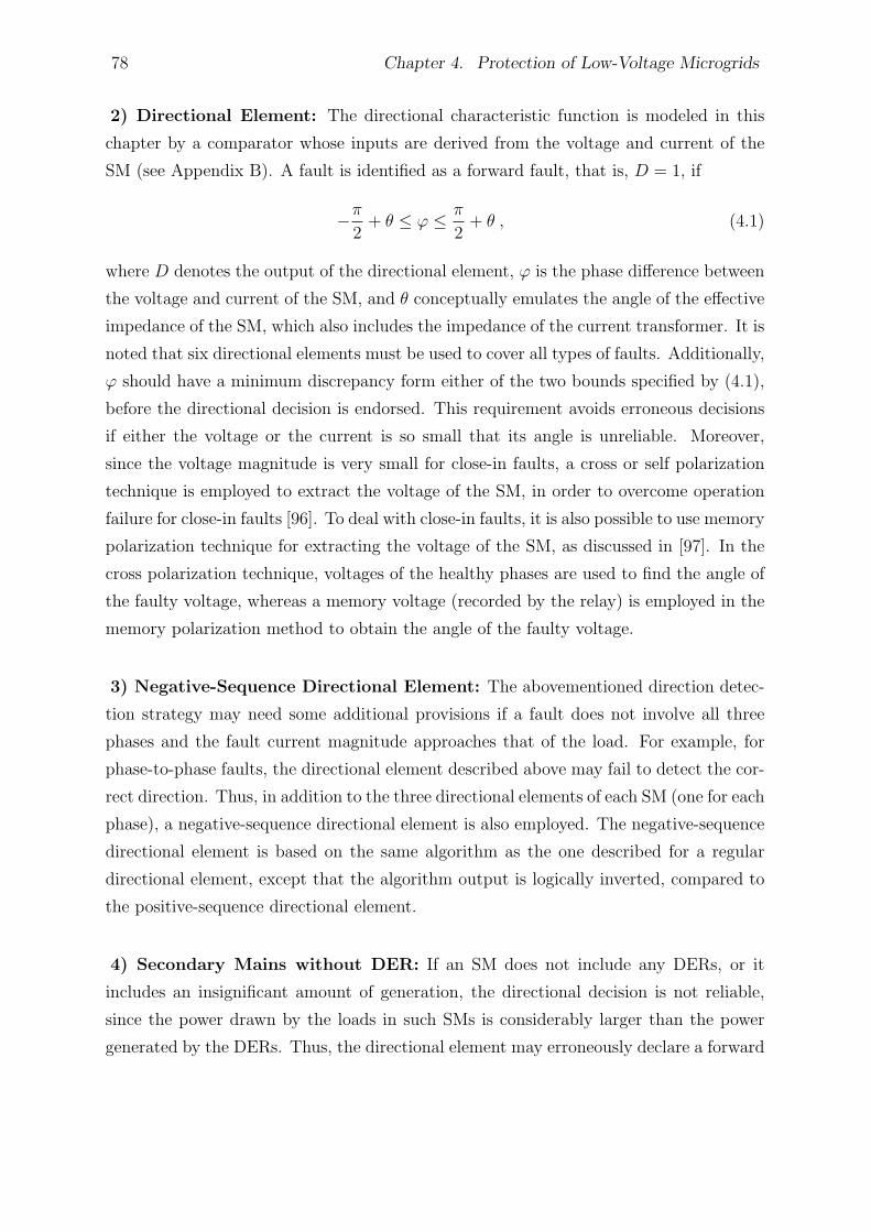
78 Chapter 4. Protection of Low-Voltage Microgrids
2) Directional Element: The directional characteristic function is modeled in this
chapter by a comparator whose inputs are derived from the voltage and current of the
SM (see Appendix B). A fault is identified as a forward fault, that is, D = 1, if
−π
2+ θ ≤ φ ≤ π
2+ θ , (4.1)
where D denotes the output of the directional element, φ is the phase difference between
the voltage and current of the SM, and θ conceptually emulates the angle of the effective
impedance of the SM, which also includes the impedance of the current transformer. It is
noted that six directional elements must be used to cover all types of faults. Additionally,
φ should have a minimum discrepancy form either of the two bounds specified by (4.1),
before the directional decision is endorsed. This requirement avoids erroneous decisions
if either the voltage or the current is so small that its angle is unreliable. Moreover,
since the voltage magnitude is very small for close-in faults, a cross or self polarization
technique is employed to extract the voltage of the SM, in order to overcome operation
failure for close-in faults [96]. To deal with close-in faults, it is also possible to use memory
polarization technique for extracting the voltage of the SM, as discussed in [97]. In the
cross polarization technique, voltages of the healthy phases are used to find the angle of
the faulty voltage, whereas a memory voltage (recorded by the relay) is employed in the
memory polarization method to obtain the angle of the faulty voltage.
3) Negative-Sequence Directional Element: The abovementioned direction detec-
tion strategy may need some additional provisions if a fault does not involve all three
phases and the fault current magnitude approaches that of the load. For example, for
phase-to-phase faults, the directional element described above may fail to detect the cor-
rect direction. Thus, in addition to the three directional elements of each SM (one for each
phase), a negative-sequence directional element is also employed. The negative-sequence
directional element is based on the same algorithm as the one described for a regular
directional element, except that the algorithm output is logically inverted, compared to
the positive-sequence directional element.
4) Secondary Mains without DER: If an SM does not include any DERs, or it
includes an insignificant amount of generation, the directional decision is not reliable,
since the power drawn by the loads in such SMs is considerably larger than the power
generated by the DERs. Thus, the directional element may erroneously declare a forward

4.3. Proposed Protection for the Islanded Mode of Operation 79
Figure 4.3: Symbolic logic circuit for substation bus protection.
direction and disconnect the SM for a fault that is in a neighboring SM. In order to
overcome this issue, this chapter proposes to supplement the aforementioned directional
decision-making strategy with a current-magnitude comparison technique. Thus, the
directional decision for a forward fault is endorsed if the current magnitude of the host
SM is larger than its full-load current magnitude. The reason for this condition is that, in
a healthy SM the current magnitude drops remarkably in the phase(s) that corresponds
to the affected phase(s) of a neighboring faulty SM.
5) Substation Bus Protection: One potential issue that may arise due to the inclusion
of directional elements is that the protection may be lost if a fault directly impacts the
substation. To circumvent this condition, all circuit breakers of the SMs that embed a
DER must be commanded to open after a time delay, once their directional elements
simultaneously detect a reverse fault. For an LV microgrid with n SMs that all of which
have DER(s), this function is realized by the logic circuit illustrated in Fig. 4.3; D1
through Dn denote the outputs of the directional elements for SM#1 through SM#n,
respectively.
4.3.5 Protection Scheme Extension
As explained in Section 4.3.2, the employment of an MPR at the beginning of each SM
ensures sufficient reliability for the host LV microgrid. However, one may prefer to extend
the protection scheme and utilize multiple MPRs along the radial SMs, to enhance the
system reliability. In case a radial SM contains more than one MPR, it is necessary to
coordinate them through a suitable grading method. Fig. 4.4 shows the basics of the
definite-time grading method, for an example LV microgrid with two SMs that employs
more than one (four, in this example) MPR in each radial SM.
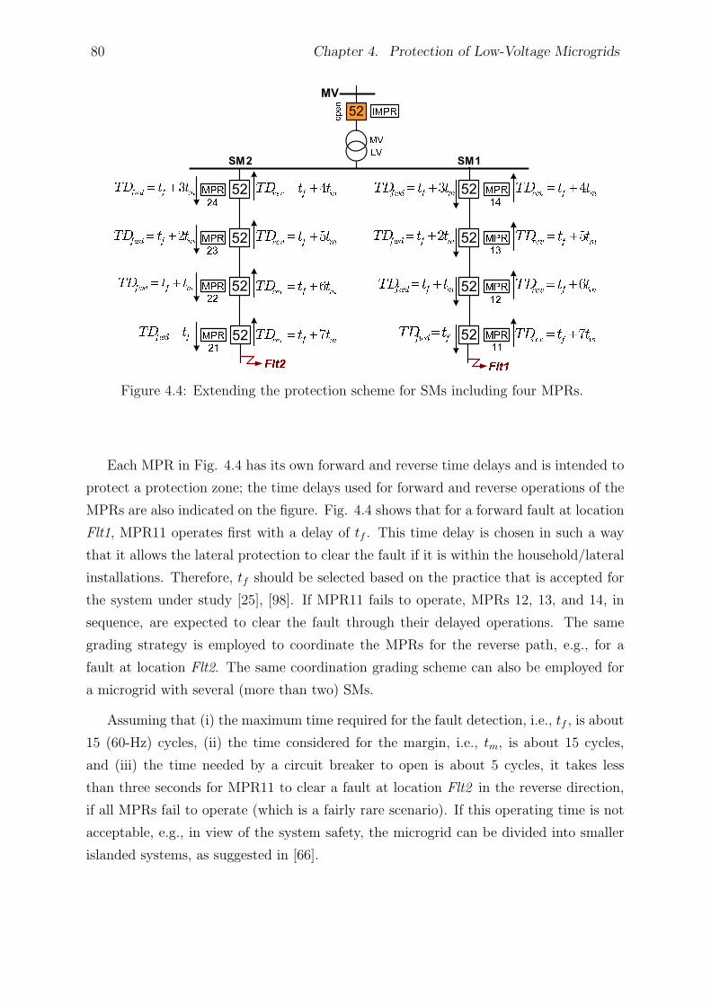
80 Chapter 4. Protection of Low-Voltage Microgrids
Figure 4.4: Extending the protection scheme for SMs including four MPRs.
Each MPR in Fig. 4.4 has its own forward and reverse time delays and is intended to
protect a protection zone; the time delays used for forward and reverse operations of the
MPRs are also indicated on the figure. Fig. 4.4 shows that for a forward fault at location
Flt1, MPR11 operates first with a delay of tf . This time delay is chosen in such a way
that it allows the lateral protection to clear the fault if it is within the household/lateral
installations. Therefore, tf should be selected based on the practice that is accepted for
the system under study [25], [98]. If MPR11 fails to operate, MPRs 12, 13, and 14, in
sequence, are expected to clear the fault through their delayed operations. The same
grading strategy is employed to coordinate the MPRs for the reverse path, e.g., for a
fault at location Flt2. The same coordination grading scheme can also be employed for
a microgrid with several (more than two) SMs.
Assuming that (i) the maximum time required for the fault detection, i.e., tf , is about
15 (60-Hz) cycles, (ii) the time considered for the margin, i.e., tm, is about 15 cycles,
and (iii) the time needed by a circuit breaker to open is about 5 cycles, it takes less
than three seconds for MPR11 to clear a fault at location Flt2 in the reverse direction,
if all MPRs fail to operate (which is a fairly rare scenario). If this operating time is not
acceptable, e.g., in view of the system safety, the microgrid can be divided into smaller
islanded systems, as suggested in [66].
4.4. Proposed Protection for the Grid-Connected Mode of Operation 81
4.4 Proposed Protection for the Grid-Connected Mode
of Operation
As mentioned earlier, the conventional overcurrent protection can still be employed for
the protection of a microgrid in the grid-connected mode of operation. The conventional
coordination practice amongst the overcurrent protective devices was also explained in
Section 1.4.1. Fig. 4.5 illustrates an example of the conventional protection coordination
for two fuses, a main relay, and a backup relay for a typical distribution network. The
figure indicates that the devices are coordinated for a fault current range, i.e., (Ifmin,
Ifmax), such that the MMT and TCT curves of the fuses lie below the characteristic
curves of the relays, to ensure that the fuses will operate before the relays intervene [25].
In addition, a coordination must also be made between the fuses (the characteristic curves
of the protective devices are described in Appendix B). If the fuses fail to operate for
a fault, the main relay will back them up by operating according to its inverse-time
characteristic. The backup relay will operate only if the main relay and the fuses fail to
act. It should be pointed out that the (main and backup) relays are normally employed
at the MV side of the substation transformer (utility grid side), and not within the LV
network (microgrid side).
102
103
104
10−3
10−2
10−1
100
101
102
103
current(A)
tim
e(s
)
Ifmin Ifmax
Fuse1 MMT
Fuse1 TCT
Fuse2 MMT
Fuse2 TCT
Backup Relay
Main Relay
Figure 4.5: Traditional coordination of fuses and relays in a typical distribution network.
82 Chapter 4. Protection of Low-Voltage Microgrids
As it is evident from Fig. 4.5, one has to ensure that the fault current passing through
the devices has a value between Ifmin and Ifmax, in order to maintain the coordination.
However, the addition of a DER to an SM, anywhere downstream of the relay, affects
Ifmax and Ifmin and also causes the fuse current to exceed the current seen by the relay
(see Section 1.4.2). Chapter 3 proposed an effective solution to accommodate the impact
of DERs on the coordination of protective devices (including reclosers), in a conventional
distribution network. The method proposed in Chapter 3 utilizes microprocessor-based
relays, but does not require communications or adaptive protective devices. Therefore,
it is also adopted in this chapter as the coordination method for the fuses and MPRs
in the grid-connected mode of operation. It is noted that, due to their limited fault
current contributions, EC-DERs cannot significantly affect the protection coordination.
In addition, it is assumed in this chapter that the secondary distribution network does
not include any recloser [86], [87]. Thus, coordination of protective devices for the grid-
connected mode of operation of an LV microgrid whose DERs are predominantly of the
electronically coupled types is more straightforward than the general example analyzed
in Chapter 3.
4.4.1 External Faults
For a fault taking place outside of the microgrid jurisdiction, a low fault current may be
contributed by the (grid-connected) microgrid, which does not guarantee the operation
of the overcurrent protection scheme of the relay that is located at the microgrid interface
point, i.e., IMPR. To address this shortcoming, the IMPR must also employ the islanded-
mode protection strategy of Section 4.3, despite the fact that it always operates in the
grid-connected mode. The only difference is that definite-time grading of the IMPR
starts at the microgrid interface point and ends at the load side of the SMs; Fig. 4.6
illustrates the process for two adjacent SMs with their respective MPRs.
4.4.2 Neutral Voltage Displacement (NVD) Protection
Another issue concerning the IMPRmay arise when the microgrid operates in the islanded
mode of operation. Although the neutral grounding of the LV microgrid is preserved due
to the LV-side star winding configuration of the step-down transformer, the MV side of
the step-down transformer, which is still energized, becomes ungrounded in the islanded
mode of operation. Therefore, overvoltages may be experienced if a ground fault impacts
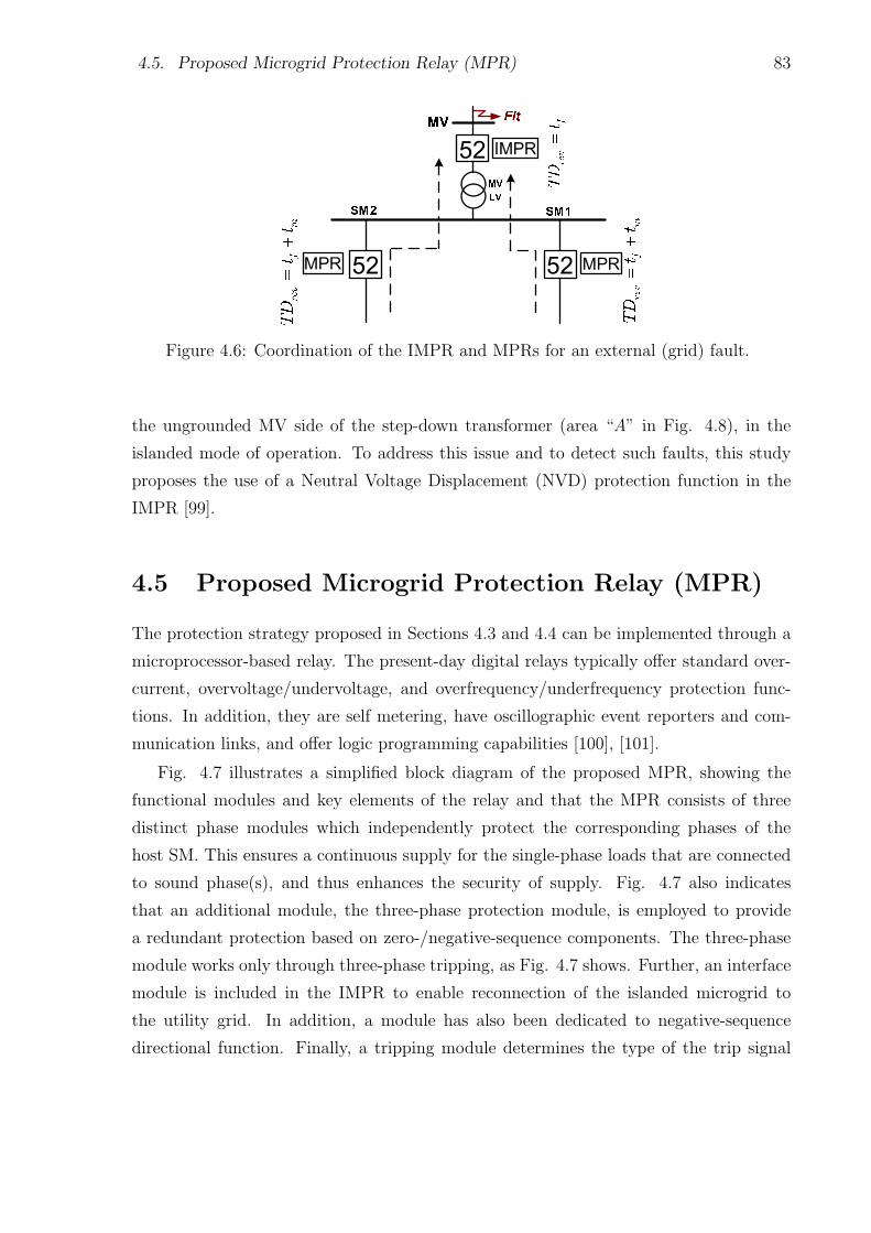
4.5. Proposed Microgrid Protection Relay (MPR) 83
Figure 4.6: Coordination of the IMPR and MPRs for an external (grid) fault.
the ungrounded MV side of the step-down transformer (area “A” in Fig. 4.8), in the
islanded mode of operation. To address this issue and to detect such faults, this study
proposes the use of a Neutral Voltage Displacement (NVD) protection function in the
IMPR [99].
4.5 Proposed Microgrid Protection Relay (MPR)
The protection strategy proposed in Sections 4.3 and 4.4 can be implemented through a
microprocessor-based relay. The present-day digital relays typically offer standard over-
current, overvoltage/undervoltage, and overfrequency/underfrequency protection func-
tions. In addition, they are self metering, have oscillographic event reporters and com-
munication links, and offer logic programming capabilities [100], [101].
Fig. 4.7 illustrates a simplified block diagram of the proposed MPR, showing the
functional modules and key elements of the relay and that the MPR consists of three
distinct phase modules which independently protect the corresponding phases of the
host SM. This ensures a continuous supply for the single-phase loads that are connected
to sound phase(s), and thus enhances the security of supply. Fig. 4.7 also indicates
that an additional module, the three-phase protection module, is employed to provide
a redundant protection based on zero-/negative-sequence components. The three-phase
module works only through three-phase tripping, as Fig. 4.7 shows. Further, an interface
module is included in the IMPR to enable reconnection of the islanded microgrid to
the utility grid. In addition, a module has also been dedicated to negative-sequence
directional function. Finally, a tripping module determines the type of the trip signal
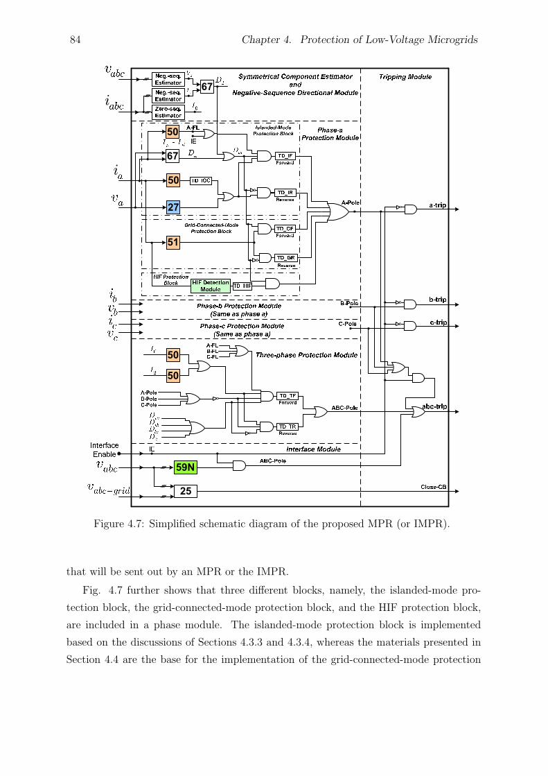
84 Chapter 4. Protection of Low-Voltage Microgrids
Figure 4.7: Simplified schematic diagram of the proposed MPR (or IMPR).
that will be sent out by an MPR or the IMPR.
Fig. 4.7 further shows that three different blocks, namely, the islanded-mode pro-
tection block, the grid-connected-mode protection block, and the HIF protection block,
are included in a phase module. The islanded-mode protection block is implemented
based on the discussions of Sections 4.3.3 and 4.3.4, whereas the materials presented in
Section 4.4 are the base for the implementation of the grid-connected-mode protection
4.6. Simulation Results 85
block. It must be noted that the forward and reverse time delays are generally different
in the islanded mode of operation, compared to the grid-connected mode of operation.
It is pointed out that HIF detection algorithm, which provides protection against HIFs,
is fairly slow compared to other modules [93]. This, however, does not pose a serious
problem since HIF currents are very small.
The three-phase protection module in the MPR of Fig. 4.7 operates with a prespeci-
fied delay should the phase protection modules fail to clear the fault (see Section 4.3.3–2).
In addition, an NVD protection elements is employed to help the IMPR detect faults at
the MV side of the step-down transformer. A synchronism-check relay is also used in
the IMPR, to ensure safe reconnection of the (islanded) microgrid to the utility grid.
The device and/or protection function numbers used in this study have been specified in
Appendix C.
4.5.1 Special Case
Typically, settings of the inverse-time overcurrent relays are determined in a manner to
provide coordination for a fairly wide range of the short-circuit capacity of the utility
grid. This is performed through the proper selection of Ifmin and Ifmax (see Chapter 3).
However, if the utility grid is so weak that the fault current magnitudes are comparable
in both modes of operation, the grid-connected-mode protection block of Fig. 4.7 is
not necessarily required, and one can deactivate it through assigning fairly large values
to time delays TD GF and TD GR. Otherwise, it will operate with a delay and may
interfere with the islanded-mode protection block, which is now responsible for protection
of the microgrid in both modes of operation. It is remembered that an instantaneous
overcurrent relay (with a prespecified time delay, TD IOC) is also utilized in the islanded-
mode protection block, as shown in Fig. 4.7.
4.6 Simulation Results
To demonstrate the effectiveness of the proposed protection scheme and the MPRs/IMPR,
a realistic LV microgrid system has been simulated in the PSCAD/EMTDC software en-
vironment. The structure of the simulated micogrid which, hereinafter, is referred to as
“study microgrid”, is almost the same as the study system of Chapter 2 and is briefly
described next; then, study cases are presented.
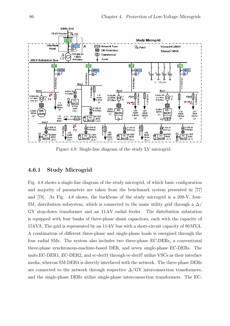
86 Chapter 4. Protection of Low-Voltage Microgrids
Figure 4.8: Single-line diagram of the study LV microgrid.
4.6.1 Study Microgrid
Fig. 4.8 shows a single-line diagram of the study microgrid, of which basic configuration
and majority of parameters are taken from the benchmark system presented in [77]
and [78]. As Fig. 4.8 shows, the backbone of the study microgrid is a 208-V, four-
SM, distribution subsystem, which is connected to the main utility grid through a ∆/
GY step-down transformer and an 11-kV radial feeder. The distribution substation
is equipped with four banks of three-phase shunt capacitors, each with the capacity of
15kVA. The grid is represented by an 11-kV bus with a short-circuit capacity of 80MVA.
A combination of different three-phase and single-phase loads is energized through the
four radial SMs. The system also includes two three-phase EC-DERs, a conventional
three-phase synchronous-machine-based DER, and seven single-phase EC-DERs. The
units EC-DER1, EC-DER2, and ec-der31 through ec-der37 utilize VSCs as their interface
media, whereas SM-DER4 is directly interfaced with the network. The three-phase DERs
are connected to the network through respective ∆/GY interconnection transformers,
and the single-phase DERs utilize single-phase interconnection transformers. The EC-
4.6. Simulation Results 87
DERs are of the wind, photovoltaic, battery, and fuel cell types, as indicated in Fig. 4.8.
To protect the microgrid, five MPRs, four at the beginning of the SMs and one at the
interface point, have been used. Fuses and traditional relaying functions are modeled in
this chapter based on the analytical equations presented in Appendix B.
4.6.2 Study Cases
1) Islanded Mode of Operation
System studies have been performed, with the MPR settings and time delays calculated
based on the strategy proposed in Sections 4.3 and 4.4; the time delays used in this
study are specified in Appendix C. Let us assume that a fault impacts the microgrid
while it is isolated from the main grid. Tables 4.2 and 4.3 report the primary and backup
relay operating times for different fault scenarios in the islanded mode of operation. A
large number of simulation tests have been conducted considering several fault scenarios;
however, due to space limitation, only a limited number of study cases have been reported
in this thesis. In the reported results, it has been tried to cover different types of faults,
different locations, and different fault resistances. Table 4.2 shows the simulation results
for solid faults while the results of Table 4.3 corresponds to high-impedance faults.
Since in the islanded mode of operation a fault results in an insufficient fault current,
the network fuses take a relatively long time to operate. Therefore, the faults are cleared
by the MPRs. For solid faults, the voltage drop across the microgrid is significant and the
undervoltage protection can detect and isolate the faults. However, for high-impedance
faults, only three-phase protection modules (3-Ph) or HIF detection modules (HIF) op-
erate, as no voltage dip is detected by the undervoltage protection function. The HIF
detection module ensures protection against HIFs even if zero-/negative-sequence current
components are smaller than the threshold values required for detection. As Table 4.3
indicates, HIF detection algorithm is fairly slow compared to other modules. HIFs are
modeled in this chapter based on the method presented in [62].
To demonstrate the effectiveness of the proposed method and MPR for the fault
scenarios in which the fault currents are very small, SM4 was disconnected from the
substation, and therefore the synchronous-machine-based DER (SM-DER4) was sent out
of service, assuming that, for example, a fault had impacted the SM. Then, similar fault
studies were conducted, and the results were found to be very similar to those of the
previous cases in which SM-DER4 was connected to the microgrid. However, only a
88 Chapter 4. Protection of Low-Voltage Microgrids
selected number of scenarios have been reported in Tables 4.2 and 4.3.
2) Grid-Connected Mode of Operation
Several cases have also been simulated for the grid-connected mode of operation but, due
to space limitations, the results of only a limited number of them have been reported
in Tables 4.4 and 4.5. Tables 4.4 and 4.5 show the primary and backup relay operating
times for different internal and external faults, at various locations, while the microgrid
operates in conjunction with the main grid. Similar to the islanded mode of operation,
it is observed that if the MPR which is responsible for the primary protection fails to
operate, other MPRs provide suitable backup protection.
4.7 Summary and Conclusion
This chapter proposed a protection strategy and an enabling relay for protection of low-
voltage microgrids in the islanded mode as well as grid-connected mode of operation. The
proposed protection strategy can be implemented through programmable microprocessor-
based relays, and can address protection issues of a microgrid in both modes of opera-
tion. The proposed strategy does not require communication links or adaptive protective
devices. More important, its effectiveness is to a large extent independent of the fault
current levels, the mode of operation, and the type and size of distributed energy resource
units, subject to the modified relay setting for the grid-connected mode of operation. Fur-
ther, the proposed protection strategy enables single-phase tripping to increase security
of supply. Several study cases were presented based on digital time-domain simulation of
a model microgrid, to demonstrate the effectiveness of the proposed protection scheme
and the enabling relay. Protection of large medium-voltage microgrid will be discussed
in the following chapter.
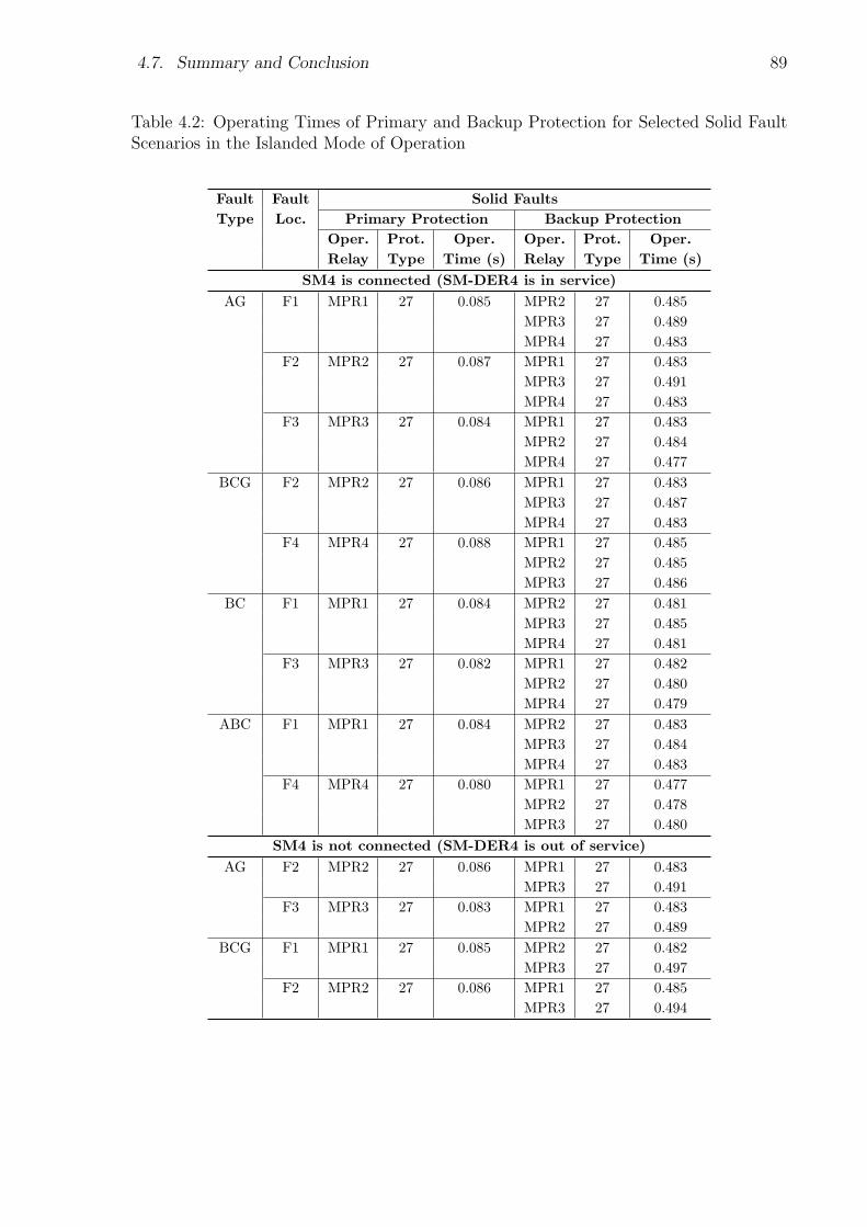
4.7. Summary and Conclusion 89
Table 4.2: Operating Times of Primary and Backup Protection for Selected Solid FaultScenarios in the Islanded Mode of Operation
Fault Fault Solid Faults
Type Loc. Primary Protection Backup Protection
Oper. Prot. Oper. Oper. Prot. Oper.
Relay Type Time (s) Relay Type Time (s)
SM4 is connected (SM-DER4 is in service)
AG F1 MPR1 27 0.085 MPR2 27 0.485
MPR3 27 0.489
MPR4 27 0.483
F2 MPR2 27 0.087 MPR1 27 0.483
MPR3 27 0.491
MPR4 27 0.483
F3 MPR3 27 0.084 MPR1 27 0.483
MPR2 27 0.484
MPR4 27 0.477
BCG F2 MPR2 27 0.086 MPR1 27 0.483
MPR3 27 0.487
MPR4 27 0.483
F4 MPR4 27 0.088 MPR1 27 0.485
MPR2 27 0.485
MPR3 27 0.486
BC F1 MPR1 27 0.084 MPR2 27 0.481
MPR3 27 0.485
MPR4 27 0.481
F3 MPR3 27 0.082 MPR1 27 0.482
MPR2 27 0.480
MPR4 27 0.479
ABC F1 MPR1 27 0.084 MPR2 27 0.483
MPR3 27 0.484
MPR4 27 0.483
F4 MPR4 27 0.080 MPR1 27 0.477
MPR2 27 0.478
MPR3 27 0.480
SM4 is not connected (SM-DER4 is out of service)
AG F2 MPR2 27 0.086 MPR1 27 0.483
MPR3 27 0.491
F3 MPR3 27 0.083 MPR1 27 0.483
MPR2 27 0.489
BCG F1 MPR1 27 0.085 MPR2 27 0.482
MPR3 27 0.497
F2 MPR2 27 0.086 MPR1 27 0.485
MPR3 27 0.494
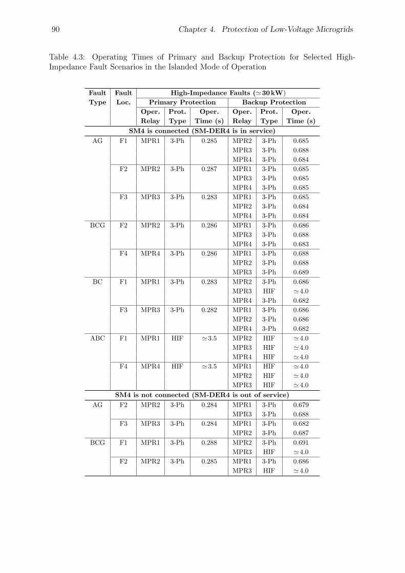
90 Chapter 4. Protection of Low-Voltage Microgrids
Table 4.3: Operating Times of Primary and Backup Protection for Selected High-Impedance Fault Scenarios in the Islanded Mode of Operation
Fault Fault High-Impedance Faults (≃30kW)
Type Loc. Primary Protection Backup Protection
Oper. Prot. Oper. Oper. Prot. Oper.
Relay Type Time (s) Relay Type Time (s)
SM4 is connected (SM-DER4 is in service)
AG F1 MPR1 3-Ph 0.285 MPR2 3-Ph 0.685
MPR3 3-Ph 0.688
MPR4 3-Ph 0.684
F2 MPR2 3-Ph 0.287 MPR1 3-Ph 0.685
MPR3 3-Ph 0.685
MPR4 3-Ph 0.685
F3 MPR3 3-Ph 0.283 MPR1 3-Ph 0.685
MPR2 3-Ph 0.684
MPR4 3-Ph 0.684
BCG F2 MPR2 3-Ph 0.286 MPR1 3-Ph 0.686
MPR3 3-Ph 0.688
MPR4 3-Ph 0.683
F4 MPR4 3-Ph 0.286 MPR1 3-Ph 0.688
MPR2 3-Ph 0.688
MPR3 3-Ph 0.689
BC F1 MPR1 3-Ph 0.283 MPR2 3-Ph 0.686
MPR3 HIF ≃4.0
MPR4 3-Ph 0.682
F3 MPR3 3-Ph 0.282 MPR1 3-Ph 0.686
MPR2 3-Ph 0.686
MPR4 3-Ph 0.682
ABC F1 MPR1 HIF ≃3.5 MPR2 HIF ≃4.0
MPR3 HIF ≃4.0
MPR4 HIF ≃4.0
F4 MPR4 HIF ≃3.5 MPR1 HIF ≃4.0
MPR2 HIF ≃4.0
MPR3 HIF ≃4.0
SM4 is not connected (SM-DER4 is out of service)
AG F2 MPR2 3-Ph 0.284 MPR1 3-Ph 0.679
MPR3 3-Ph 0.688
F3 MPR3 3-Ph 0.284 MPR1 3-Ph 0.682
MPR2 3-Ph 0.687
BCG F1 MPR1 3-Ph 0.288 MPR2 3-Ph 0.691
MPR3 HIF ≃4.0
F2 MPR2 3-Ph 0.285 MPR1 3-Ph 0.686
MPR3 HIF ≃4.0
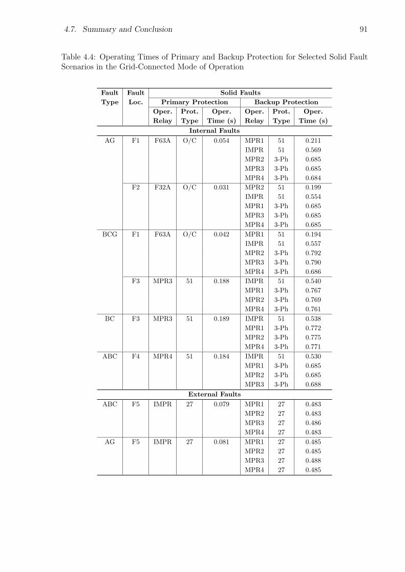
4.7. Summary and Conclusion 91
Table 4.4: Operating Times of Primary and Backup Protection for Selected Solid FaultScenarios in the Grid-Connected Mode of Operation
Fault Fault Solid Faults
Type Loc. Primary Protection Backup Protection
Oper. Prot. Oper. Oper. Prot. Oper.
Relay Type Time (s) Relay Type Time (s)
Internal Faults
AG F1 F63A O/C 0.054 MPR1 51 0.211
IMPR 51 0.569
MPR2 3-Ph 0.685
MPR3 3-Ph 0.685
MPR4 3-Ph 0.684
F2 F32A O/C 0.031 MPR2 51 0.199
IMPR 51 0.554
MPR1 3-Ph 0.685
MPR3 3-Ph 0.685
MPR4 3-Ph 0.685
BCG F1 F63A O/C 0.042 MPR1 51 0.194
IMPR 51 0.557
MPR2 3-Ph 0.792
MPR3 3-Ph 0.790
MPR4 3-Ph 0.686
F3 MPR3 51 0.188 IMPR 51 0.540
MPR1 3-Ph 0.767
MPR2 3-Ph 0.769
MPR4 3-Ph 0.761
BC F3 MPR3 51 0.189 IMPR 51 0.538
MPR1 3-Ph 0.772
MPR2 3-Ph 0.775
MPR4 3-Ph 0.771
ABC F4 MPR4 51 0.184 IMPR 51 0.530
MPR1 3-Ph 0.685
MPR2 3-Ph 0.685
MPR3 3-Ph 0.688
External Faults
ABC F5 IMPR 27 0.079 MPR1 27 0.483
MPR2 27 0.483
MPR3 27 0.486
MPR4 27 0.483
AG F5 IMPR 27 0.081 MPR1 27 0.485
MPR2 27 0.485
MPR3 27 0.488
MPR4 27 0.485
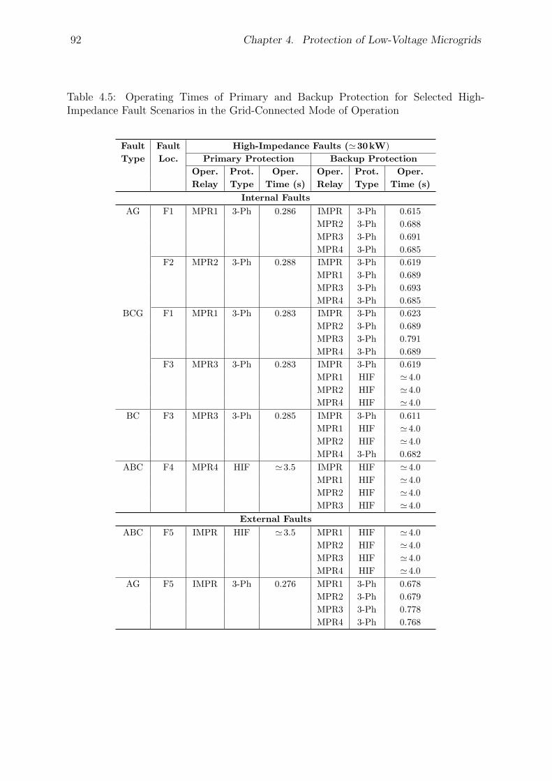
92 Chapter 4. Protection of Low-Voltage Microgrids
Table 4.5: Operating Times of Primary and Backup Protection for Selected High-Impedance Fault Scenarios in the Grid-Connected Mode of Operation
Fault Fault High-Impedance Faults (≃30kW)
Type Loc. Primary Protection Backup Protection
Oper. Prot. Oper. Oper. Prot. Oper.
Relay Type Time (s) Relay Type Time (s)
Internal Faults
AG F1 MPR1 3-Ph 0.286 IMPR 3-Ph 0.615
MPR2 3-Ph 0.688
MPR3 3-Ph 0.691
MPR4 3-Ph 0.685
F2 MPR2 3-Ph 0.288 IMPR 3-Ph 0.619
MPR1 3-Ph 0.689
MPR3 3-Ph 0.693
MPR4 3-Ph 0.685
BCG F1 MPR1 3-Ph 0.283 IMPR 3-Ph 0.623
MPR2 3-Ph 0.689
MPR3 3-Ph 0.791
MPR4 3-Ph 0.689
F3 MPR3 3-Ph 0.283 IMPR 3-Ph 0.619
MPR1 HIF ≃4.0
MPR2 HIF ≃4.0
MPR4 HIF ≃4.0
BC F3 MPR3 3-Ph 0.285 IMPR 3-Ph 0.611
MPR1 HIF ≃4.0
MPR2 HIF ≃4.0
MPR4 3-Ph 0.682
ABC F4 MPR4 HIF ≃3.5 IMPR HIF ≃4.0
MPR1 HIF ≃4.0
MPR2 HIF ≃4.0
MPR3 HIF ≃4.0
External Faults
ABC F5 IMPR HIF ≃3.5 MPR1 HIF ≃4.0
MPR2 HIF ≃4.0
MPR3 HIF ≃4.0
MPR4 HIF ≃4.0
AG F5 IMPR 3-Ph 0.276 MPR1 3-Ph 0.678
MPR2 3-Ph 0.679
MPR3 3-Ph 0.778
MPR4 3-Ph 0.768
Chapter 5
Protection of Medium-Voltage
Microgrids
5.1 Introduction
The protection strategy proposed in Chapter 4, for LV microgrids, does not require com-
munications or adaptive settings; however, since it relies on the definite-time grading
technique for coordination of relays, it may take a relatively long time to isolate a fault
within a large medium-voltage (MV) microgrid (especially in the islanded mode of opera-
tion). Therefore, a faster protection strategy should be devised for large MV microgrids,
where fast fault clearance is desired. On the other hand, with the advent of the “Smart
Grid” concept, the future power system is envisioned to heavily rely on communications
and massive computing power. Thus, a communication-based protection scheme would
be a possible option for the protection of large MV microgrids, where a more rapid and
faithful protection scheme is required.
This chapter proposes a communication-assisted protection strategy implementable
by commercially available microprocessor-based relays for protection of MV microgrids.
Even though the developed protection strategy benefits from communications, it offers a
backup protection strategy to manage communication network failures; this ensures that
the network is always protected. The strategy is effective in both modes of operation, and
does not require to detect the mode of operation and switch between different protection
schemes (for the grid-connected and islanded modes). The structure of the relay proposed
in Chapter 4 is also modified in this chapter; the modified relay enables the designer
to implement the proposed protection strategy. Comprehensive simulation studies are
93
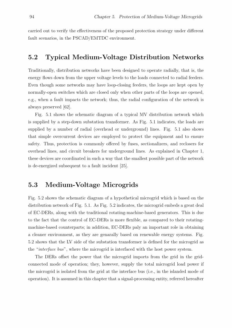
94 Chapter 5. Protection of Medium-Voltage Microgrids
carried out to verify the effectiveness of the proposed protection strategy under different
fault scenarios, in the PSCAD/EMTDC environment.
5.2 Typical Medium-Voltage Distribution Networks
Traditionally, distribution networks have been designed to operate radially, that is, the
energy flows down from the upper voltage levels to the loads connected to radial feeders.
Even though some networks may have loop-closing feeders, the loops are kept open by
normally-open switches which are closed only when other parts of the loops are opened,
e.g., when a fault impacts the network; thus, the radial configuration of the network is
always preserved [62].
Fig. 5.1 shows the schematic diagram of a typical MV distribution network which
is supplied by a step-down substation transformer. As Fig. 5.1 indicates, the loads are
supplied by a number of radial (overhead or underground) lines. Fig. 5.1 also shows
that simple overcurrent devices are employed to protect the equipment and to ensure
safety. Thus, protection is commonly offered by fuses, sectionalizers, and reclosers for
overhead lines, and circuit breakers for underground lines. As explained in Chapter 1,
these devices are coordinated in such a way that the smallest possible part of the network
is de-energized subsequent to a fault incident [25].
5.3 Medium-Voltage Microgrids
Fig. 5.2 shows the schematic diagram of a hypothetical microgrid which is based on the
distribution network of Fig. 5.1. As Fig. 5.2 indicates, the microgrid embeds a great deal
of EC-DERs, along with the traditional rotating-machine-based generators. This is due
to the fact that the control of EC-DERs is more flexible, as compared to their rotating-
machine-based counterparts; in addition, EC-DERs paly an important role in obtaining
a cleaner environment, as they are genarally based on renewable energy systems. Fig.
5.2 shows that the LV side of the substation transformer is defined for the microgrid as
the “interface bus”, where the microgrid is interfaced with the host power system.
The DERs offset the power that the microgrid imports from the grid in the grid-
connected mode of operation; they, however, supply the total microgrid load power if
the microgrid is isolated from the grid at the interface bus (i.e., in the islanded mode of
operation). It is assumed in this chapter that a signal-processing entity, referred hereafter
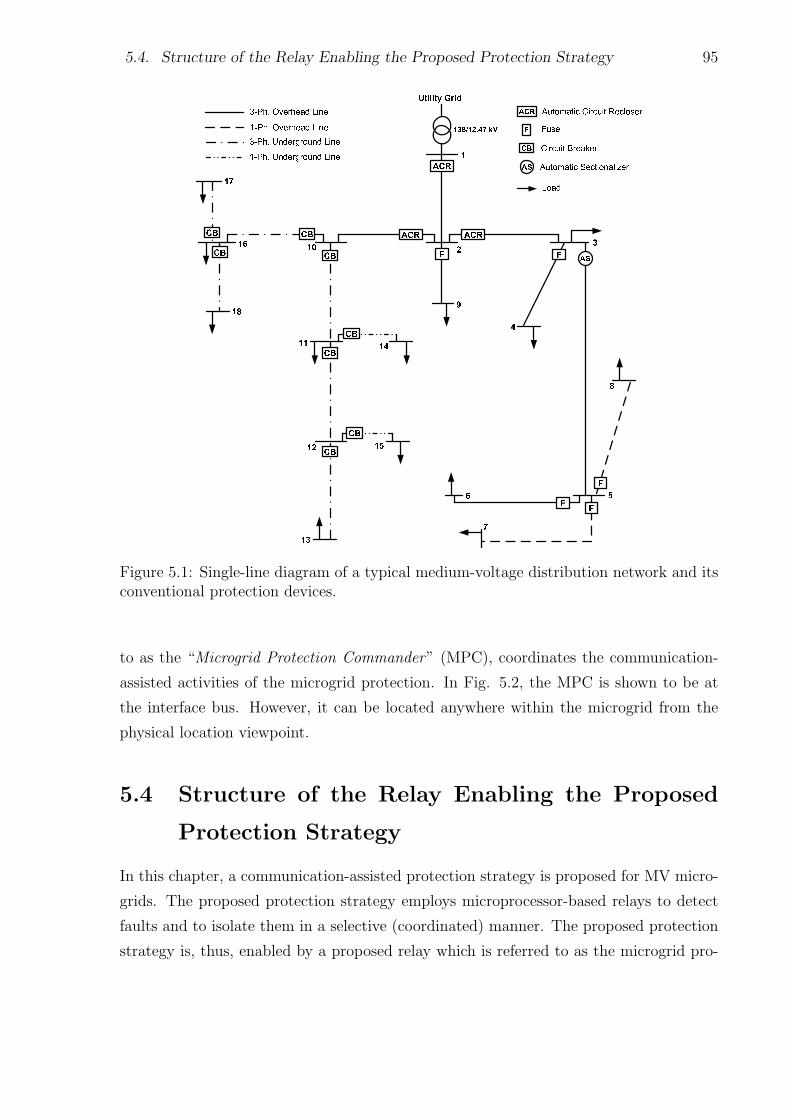
5.4. Structure of the Relay Enabling the Proposed Protection Strategy 95
Figure 5.1: Single-line diagram of a typical medium-voltage distribution network and itsconventional protection devices.
to as the “Microgrid Protection Commander” (MPC), coordinates the communication-
assisted activities of the microgrid protection. In Fig. 5.2, the MPC is shown to be at
the interface bus. However, it can be located anywhere within the microgrid from the
physical location viewpoint.
5.4 Structure of the Relay Enabling the Proposed
Protection Strategy
In this chapter, a communication-assisted protection strategy is proposed for MV micro-
grids. The proposed protection strategy employs microprocessor-based relays to detect
faults and to isolate them in a selective (coordinated) manner. The proposed protection
strategy is, thus, enabled by a proposed relay which is referred to as the microgrid pro-
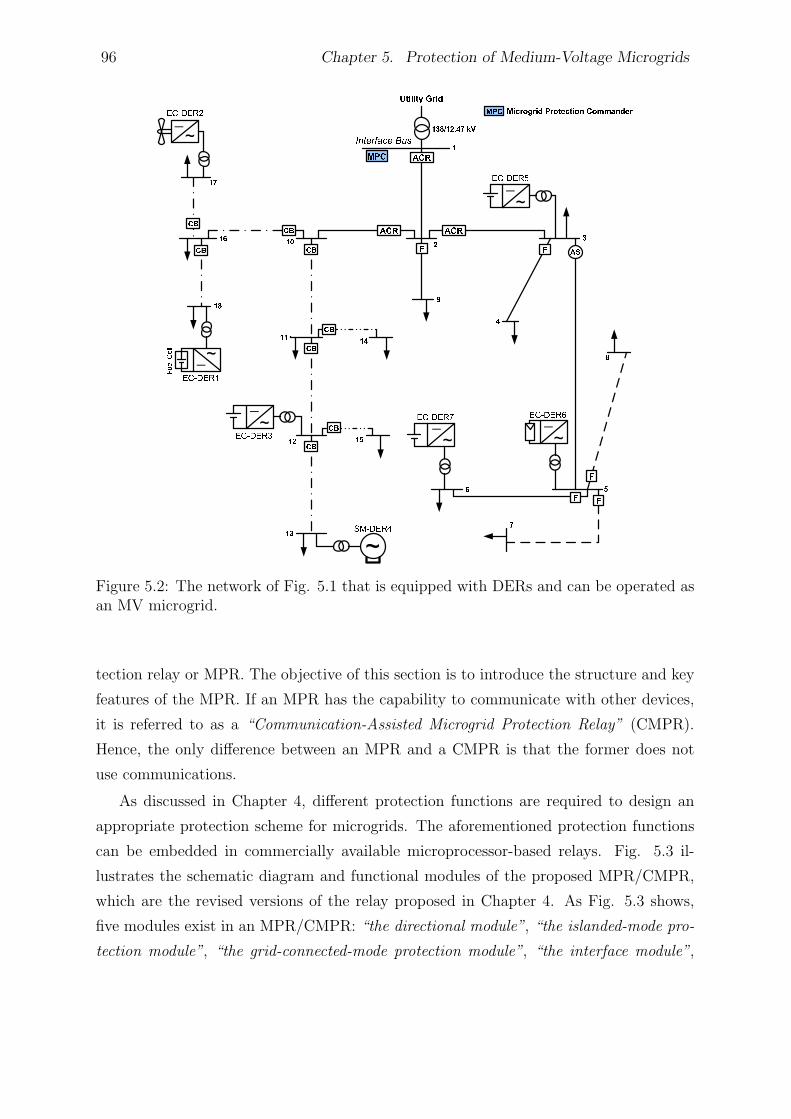
96 Chapter 5. Protection of Medium-Voltage Microgrids
Figure 5.2: The network of Fig. 5.1 that is equipped with DERs and can be operated asan MV microgrid.
tection relay or MPR. The objective of this section is to introduce the structure and key
features of the MPR. If an MPR has the capability to communicate with other devices,
it is referred to as a “Communication-Assisted Microgrid Protection Relay” (CMPR).
Hence, the only difference between an MPR and a CMPR is that the former does not
use communications.
As discussed in Chapter 4, different protection functions are required to design an
appropriate protection scheme for microgrids. The aforementioned protection functions
can be embedded in commercially available microprocessor-based relays. Fig. 5.3 il-
lustrates the schematic diagram and functional modules of the proposed MPR/CMPR,
which are the revised versions of the relay proposed in Chapter 4. As Fig. 5.3 shows,
five modules exist in an MPR/CMPR: “the directional module”, “the islanded-mode pro-
tection module”, “the grid-connected-mode protection module”, “the interface module”,
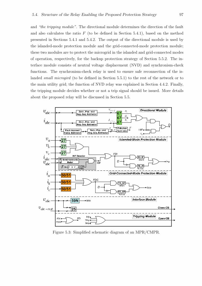
5.4. Structure of the Relay Enabling the Proposed Protection Strategy 97
and “the tripping module”. The directional module determines the direction of the fault
and also calculates the ratio F (to be defined in Section 5.4.1), based on the method
presented in Sections 5.4.1 and 5.4.2. The output of the directional module is used by
the islanded-mode protection module and the grid-connected-mode protection module;
these two modules are to protect the microgrid in the islanded and grid-connected modes
of operation, respectively, for the backup protection strategy of Section 5.5.2. The in-
terface module consists of neutral voltage displacement (NVD) and synchronism-check
functions. The synchronism-check relay is used to ensure safe reconnection of the is-
landed small microgird (to be defined in Section 5.5.1) to the rest of the network or to
the main utility grid; the function of NVD relay was explained in Section 4.4.2. Finally,
the tripping module decides whether or not a trip signal should be issued. More details
about the proposed relay will be discussed in Section 5.5.
Figure 5.3: Simplified schematic diagram of an MPR/CMPR.
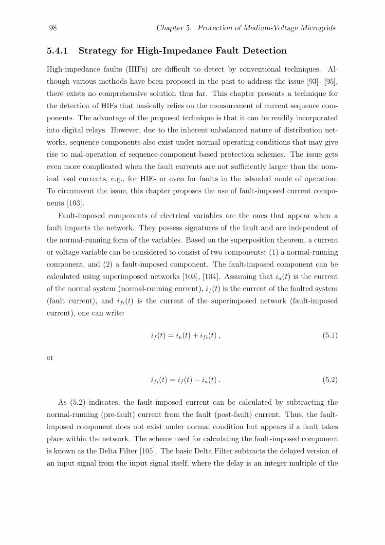
98 Chapter 5. Protection of Medium-Voltage Microgrids
5.4.1 Strategy for High-Impedance Fault Detection
High-impedance faults (HIFs) are difficult to detect by conventional techniques. Al-
though various methods have been proposed in the past to address the issue [93]- [95],
there exists no comprehensive solution thus far. This chapter presents a technique for
the detection of HIFs that basically relies on the measurement of current sequence com-
ponents. The advantage of the proposed technique is that it can be readily incorporated
into digital relays. However, due to the inherent unbalanced nature of distribution net-
works, sequence components also exist under normal operating conditions that may give
rise to mal-operation of sequence-component-based protection schemes. The issue gets
even more complicated when the fault currents are not sufficiently larger than the nom-
inal load currents, e.g., for HIFs or even for faults in the islanded mode of operation.
To circumvent the issue, this chapter proposes the use of fault-imposed current compo-
nents [103].
Fault-imposed components of electrical variables are the ones that appear when a
fault impacts the network. They possess signatures of the fault and are independent of
the normal-running form of the variables. Based on the superposition theorem, a current
or voltage variable can be considered to consist of two components: (1) a normal-running
component, and (2) a fault-imposed component. The fault-imposed component can be
calculated using superimposed networks [103], [104]. Assuming that in(t) is the current
of the normal system (normal-running current), if (t) is the current of the faulted system
(fault current), and ifi(t) is the current of the superimposed network (fault-imposed
current), one can write:
if (t) = in(t) + ifi(t) , (5.1)
or
ifi(t) = if (t)− in(t) . (5.2)
As (5.2) indicates, the fault-imposed current can be calculated by subtracting the
normal-running (pre-fault) current from the fault (post-fault) current. Thus, the fault-
imposed component does not exist under normal condition but appears if a fault takes
place within the network. The scheme used for calculating the fault-imposed component
is known as the Delta Filter [105]. The basic Delta Filter subtracts the delayed version of
an input signal from the input signal itself, where the delay is an integer multiple of the
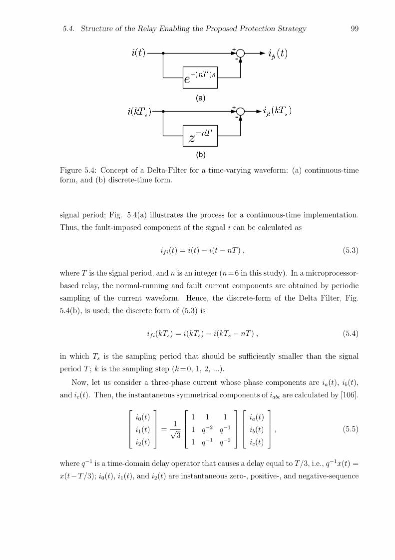
5.4. Structure of the Relay Enabling the Proposed Protection Strategy 99
Figure 5.4: Concept of a Delta-Filter for a time-varying waveform: (a) continuous-timeform, and (b) discrete-time form.
signal period; Fig. 5.4(a) illustrates the process for a continuous-time implementation.
Thus, the fault-imposed component of the signal i can be calculated as
ifi(t) = i(t)− i(t− nT ) , (5.3)
where T is the signal period, and n is an integer (n=6 in this study). In a microprocessor-
based relay, the normal-running and fault current components are obtained by periodic
sampling of the current waveform. Hence, the discrete-form of the Delta Filter, Fig.
5.4(b), is used; the discrete form of (5.3) is
ifi(kTs) = i(kTs)− i(kTs − nT ) , (5.4)
in which Ts is the sampling period that should be sufficiently smaller than the signal
period T ; k is the sampling step (k=0, 1, 2, ...).
Now, let us consider a three-phase current whose phase components are ia(t), ib(t),
and ic(t). Then, the instantaneous symmetrical components of iabc are calculated by [106].i0(t)
i1(t)
i2(t)
=1√3
1 1 1
1 q−2 q−1
1 q−1 q−2
ia(t)
ib(t)
ic(t)
, (5.5)
where q−1 is a time-domain delay operator that causes a delay equal to T/3, i.e., q−1x(t) =
x(t−T/3); i0(t), i1(t), and i2(t) are instantaneous zero-, positive-, and negative-sequence
100 Chapter 5. Protection of Medium-Voltage Microgrids
components, respectively. The current iabc(t) can be the normal-running current, the
fault current, or the fault-imposed current. Thus, (5.5) provides three corresponding sets
of sequence components which can be used to define a ratio, [107], [108], that is hereafter
called the “system imbalance ratio”. This ratio, denoted by R, shows the change in the
zero- and negative-sequence components relative to the positive-sequence component and
is defined as
R =|i0(t)|+ |i2(t)|
|i1(t)|, (5.6)
where |i0(t)|, |i1(t)|, and |i2(t)| are the rms values of the zero-, positive-, and negative-
sequence components, respectively. Let Rn, Rf , and Rfi be the values of R when iabc(t) is
respectively the normal-running current, the fault current, and the fault-imposed current.
Then, it is noted that the ratio Rn is not zero since distribution networks are inherently
unbalanced; the system imbalance, however, is not very large under normal conditions,
and it is typically less than 20% [92], [109], [110]. When a solid fault strikes the system,
Rn changes significantly (to the value of Rf ). Therefore, Rf is an effective means for
detecting solid faults. On the other hand, the zero- and negative-sequence components
corresponding to a HIF are not necessarily larger than their counterparts under a normal-
running condition and, therefore, one cannot ignore the system imbalance when detecting
HIFs. To address the issue, this chapter proposes the use of the fault-imposed component
for fault detection, i.e., instead of Rf the ratio Rfi is used to detect faults. To further
desensitize the protection algorithm, this chapter also proposes a new ratio, the “fault
ratio”, for detecting HIFs; the fault ratio is defined as
F =Rfi
Rn
. (5.7)
As compared to R, which represents the change in the zero- and negative-sequence
components with respect to the positive-sequence component, the ratio F indicates the
change in the sequence components, from the normal-running condition to the fault
condition. Therefore, F is less sensitive to network imbalance and can be effectively
used for fault detection. If F is larger than a threshold, Fset, for a prespecified period of
time, the presence of a fault is established, and an action is taken based on the proposed
coordination strategy of Section 5.5; in this study, the threshold Fset has been assumed
to be 1.2. One problem associated with the proposed fault detection scheme is that it
may fail to operate for high-impedance three-phase-to-ground faults. This, however, is
5.5. Proposed Protection Strategy 101
not very problematic since: (i) a very small percentage of the network faults (less that
0.1%, if not zero) are of high-impedance three-phase-to-ground type, and (ii) the current
level for this type of fault is in the range of load current, and is unlikely to damage the
system equipment in a short time. However, to prevent safety risks to the public, further
studies should be conducted to resolve this issue.
Another issue concerning the HIF detection strategy arises when a single-phasing
incident takes place, during which one phase of a three-phase circuit is missing or de-
energized. Thus, the proposed strategy may not be able to distinguish a single-phasing
event from a HIF. To address the issue, the HIF detection strategy is augmented with
a “third harmonic meter” block, as shown in Fig. 5.3. The block monitors the changes
in the magnitude and phase angle of the feeder third harmonic current, as these changes
follow a unique pattern for HIFs [95]. It should be noted that the third-harmonic meter
is not able to detect all HIFs solely [93] and, thus, the use of the proposed HIF detection
strategy along with this block is necessary.
5.4.2 Directional Decision Making
The proposed communication-assisted protection strategy requires directional elements
which are simulated based on the method presented in Chapter 4. When a HIF impacts
the network, the directional elements may fail to indicate the correct location of the fault.
To deal with the issue, this chapter proposes the employment of zero-sequence directional
elements; the strategy is similar to the one exercised in directional groundfault relays to
protect isolated-neutral or impedance-grounded networks, where the fault current may
be small [103], [111]. Moreover, a negative-sequence directional element is used to ensure
protection against faults with small current magnitudes that do not include all three
phases, e.g., phase-to-phase faults [97]. As shown in Fig. 5.3, different combinations
of zero-, negative-, and positive-sequence directional signals are used in the proposed
strategy to constitute the main directional signal, D, according to the fault type [96].
5.5 Proposed Protection Strategy
This section describes the proposed communication-assisted protection strategy, enabled
by the relay of Section 5.4. The proposed protection strategy offers the main and backup
protections.
102 Chapter 5. Protection of Medium-Voltage Microgrids
5.5.1 Main Protection
Based on the proposed protection strategy, a microgrid is devided into a desired number
of subnetworks so that each can be isolated from the rest of the microgrid through the
commands delivered to one or more CMPRs. This requires that some protective devices
of the original distribution network be replaced by CMPRs, each protecting a corre-
sponding subnetwork. The division of the microgrid into the subnetworks is performed
based on the system requirements, constraints, and configuration; however, the proposed
protection strategy would be even more effective if a generation-demand balance existed
within the subnetworks so that they could be operated as islands. If that is the case,
some protective devices within each subnetwork could also be replaced by MPRs to pro-
vide higher reliability and isolate the faults within each subnetwork. Otherwise, the
subnetworks must be dropped out when they get islanded, due to a fault either within
themselves or in their neighboring subnetworks. Therefore, the use of MPRs is optional;
the number of the MPRs that are employed in each subnetwork is determined based on
the required reliability. Hereafter, a subnetwork is referred to as a “small microgrid”,
even if it cannot be operated autonomously.
The proposed strategy assumes that each CMPR (which is responsible for protecting
a corresponding small microgrid) sends two signals to the MPC: (1) the “fault detection
signal” (FD) which indicates whether or not the CMPR has detected a fault within its
jurisdiction, and (2) the “fault direction signal” (D) which indicates the direction of the
fault from the CMPR prospective; the derivations of FD and D were explained in Sections
5.4.1 and 5.4.2, respectively. The MPC receives the signals FD and D from all CMPRs
and determines, through a suitable logic mechanism, the small microgrid in which a fault
has occurred. The logic algorithm is similar to the “directional comparison” protection
method and will be explained in more detail in Section 5.6.
Once the occurrence of a fault is established (by the use of FD signals), the MPC
waits for a short prespecified time to receive new directional signals and determine the
faulty small microgrid. Then, appropriate trip signals are sent to the circuit breakers
associated with the CMPRs, to open and isolate the impacted small microgrid. The trip
signals are sent after a time delay (greater than 0.1s, but less than 0.15s [25], [98]) in
order to give a chance to the downstream protective devices to operate first (especially,
in the grid-connected mode of operation where the fault currents are fairly large). Hence,
the proposed protection strategy is applicable irrespective of the mode of operation. Due
to the limited geographical spans of a small microgrid, the aforementioned definite-time
5.5. Proposed Protection Strategy 103
margin can satisfy coordination of the CMPRs with the downstream devices, for the
main protection. However, to make sure that each CMPR gives enough chance to its
downstream protective devices to operate, one may choose different time delays for the
CMPRs, in the program that is loaded into the MPC.
If a circuit breaker fails, a breaker failure trip signal is sent to the neighboring circuit
breakers such that the smallest possible area of the microgrid is isolated. The breaker
failure trip signal is sent after a time delay (greater than 0.3s, but less than 0.4s) if any
of the fault detection signals is still active; the time delays are selected based on common
practices [25]. The backup protection mode is enabled after about 0.4s from the fault
incident and, thus, gives a chance to the first two aforementioned trip signals to be sent.
Therefore, if the communication link fails and the CMPRs do not receive any signal for
some time, all CMPRs will be automatically switched to the backup protection mode.
The backup protection does not require communications, but, compared to the main
protection, may take a relatively long time to operate (the backup protection strategy is
explained in Section 5.5.2). Fig. 5.5 provides a flowchart of the proposed communication-
assisted protection algorithm.
Once an impacted small microgrid is disconnected from the rest of the microgrid,
one of the two following actions can be exercised if the fault persists: (i) the entire
small microgrid is dropped out after a prespecified time delay, or (ii) the fault is isolated
by the MPRs embedded in the small microgrid, and the small microgrid is operated
autonomously (see Section 5.6). The MPRs must be coordinated with the existing con-
ventional protective devices based on the backup protection strategy of Section 5.5.2. It
should be pointed out that the strategy (ii) above is applicable if there is a generation-
load match in the affected small microgrid. This strategy enhances the continuity of
service, albeit at the higher cost. If the fault is temporary and cleared after the isolation
of the small microgrid from the rest of the microgrid, the islanded small microgrid can
be synchronized to the rest of the network through the built-in synchronization schemes
of its DERs (see Chapter 2).
It should be pointed out that the proposed protection strategy can be augmented with
the automatic reclosing. To do so, once the MPC detects a fault within a small microgrid,
it should immediately send trip signals to the corresponding CMPR(s) to isolate the
faulty small microgrid instantaneously. At the same time, trip signals are also sent to
the DERs embedded in the impacted small microgrid, to disconnect them. Therefore,
when the CMPR recloses the circuit, after the reclosing dead time, no DER is connected
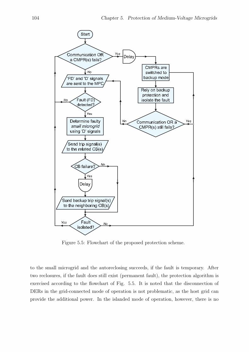
104 Chapter 5. Protection of Medium-Voltage Microgrids
Figure 5.5: Flowchart of the proposed protection scheme.
to the small microgrid and the autoreclosing succeeds, if the fault is temporary. After
two reclosures, if the fault does still exist (permanent fault), the protection algorithm is
exercised according to the flowchart of Fig. 5.5. It is noted that the disconnection of
DERs in the grid-connected mode of operation is not problematic, as the host grid can
provide the additional power. In the islanded mode of operation, however, there is no
5.5. Proposed Protection Strategy 105
connection to the grid, and one cannot ensure successful autoreclosing. One scenario that
could be envisioned is to disable reclosing mechanism of the CMPRs once the microgrid
gets islanded. This can be done by sending a disabling signal to the CMPRs, based on
the status of the interface circuit breaker, that is, the circuit breaker that connects the
microgrid to the main grid.
Communication Medium: To implement the proposed protection strategy, one can
utilize the communication capabilities of the smart grid. For example, if the smart grid
technologies have already been developed, the corresponding communication channel can
be used for the proposed protection strategy. With the advancements in wireless commu-
nications, standardized technologies are offered for wide area, metropolitan area, local
area, and personal area networks. Compared to wired communications, wireless com-
munications has several advantages including low installation cost, rapid deployment,
remote location coverage, and high mobility [112]. For distances under 30 kilometers,
wireless signal transmissions take less than 1ms (including the processing time), which
is acceptable for most distribution network applications [62], as well as for the proposed
protection strategy. For distances larger than 30 kilometers, however, a phasor measure-
ment unit (PMU) may be required to synchronize the measured signals.
One possible communication option1 for the proposed protection strategy is IEEE
802.11 based Wireless Local Area Network (WLAN) protocol, augmented with long-
range wireless Ethernet Bridge. IEEE 802.11 based WLAN provides robust, high speed
point-to-point and point-to-multipoint communications [113]. With the use of long-range
Ethernet Bridge, the WLAN technology provides a long coverage in excess of 80 kilo-
meters (for example, see reference [114]). The commercially available wireless Ethernet
Bridge, besides having a link to another Bridge, can also operate as an access point for
up to 32 additional remote Bridges. Further, current technologies based on IEEE 802.11a
can provide data rates up to 54 Mbps. The proposed option is a fairly economical choice,
and can be extended in case of the future development of the distribution network. Fig.
5.6 illustrates a simplified schematic diagram of the proposed communication medium
for an example microgrid. As Fig. 5.6 shows, the proposed communication medium has
the capability to be developed for the future upgrades.
1One other option could be long-range radio modem that benefits from serial communications. Theonly issue with radio modems is that they are based on point-to-point communications, which is trans-lated into a slightly higher cost compared to the WLAN technology.
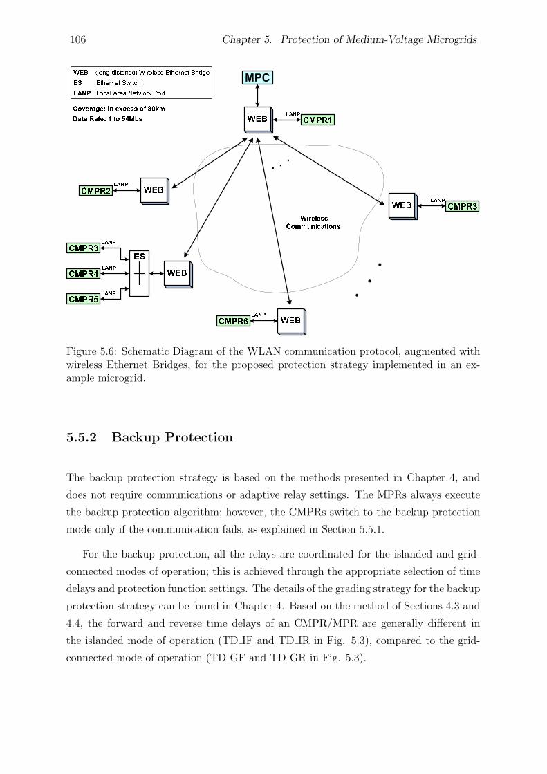
106 Chapter 5. Protection of Medium-Voltage Microgrids
Figure 5.6: Schematic Diagram of the WLAN communication protocol, augmented withwireless Ethernet Bridges, for the proposed protection strategy implemented in an ex-ample microgrid.
5.5.2 Backup Protection
The backup protection strategy is based on the methods presented in Chapter 4, and
does not require communications or adaptive relay settings. The MPRs always execute
the backup protection algorithm; however, the CMPRs switch to the backup protection
mode only if the communication fails, as explained in Section 5.5.1.
For the backup protection, all the relays are coordinated for the islanded and grid-
connected modes of operation; this is achieved through the appropriate selection of time
delays and protection function settings. The details of the grading strategy for the backup
protection strategy can be found in Chapter 4. Based on the method of Sections 4.3 and
4.4, the forward and reverse time delays of an CMPR/MPR are generally different in
the islanded mode of operation (TD IF and TD IR in Fig. 5.3), compared to the grid-
connected mode of operation (TD GF and TD GR in Fig. 5.3).
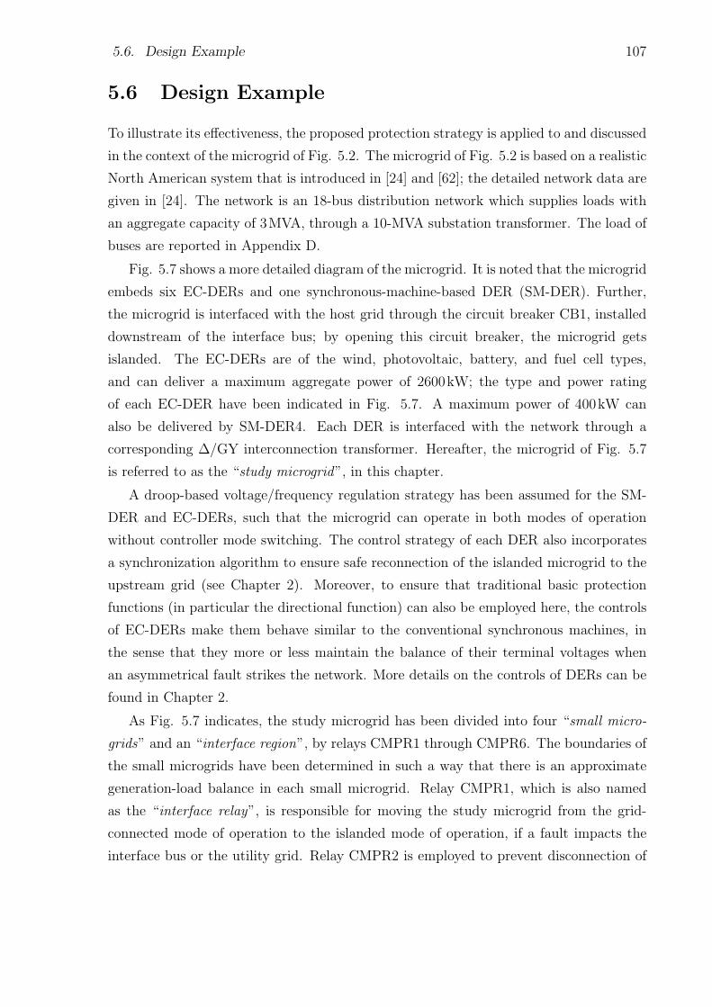
5.6. Design Example 107
5.6 Design Example
To illustrate its effectiveness, the proposed protection strategy is applied to and discussed
in the context of the microgrid of Fig. 5.2. The microgrid of Fig. 5.2 is based on a realistic
North American system that is introduced in [24] and [62]; the detailed network data are
given in [24]. The network is an 18-bus distribution network which supplies loads with
an aggregate capacity of 3MVA, through a 10-MVA substation transformer. The load of
buses are reported in Appendix D.
Fig. 5.7 shows a more detailed diagram of the microgrid. It is noted that the microgrid
embeds six EC-DERs and one synchronous-machine-based DER (SM-DER). Further,
the microgrid is interfaced with the host grid through the circuit breaker CB1, installed
downstream of the interface bus; by opening this circuit breaker, the microgrid gets
islanded. The EC-DERs are of the wind, photovoltaic, battery, and fuel cell types,
and can deliver a maximum aggregate power of 2600kW; the type and power rating
of each EC-DER have been indicated in Fig. 5.7. A maximum power of 400kW can
also be delivered by SM-DER4. Each DER is interfaced with the network through a
corresponding ∆/GY interconnection transformer. Hereafter, the microgrid of Fig. 5.7
is referred to as the “study microgrid”, in this chapter.
A droop-based voltage/frequency regulation strategy has been assumed for the SM-
DER and EC-DERs, such that the microgrid can operate in both modes of operation
without controller mode switching. The control strategy of each DER also incorporates
a synchronization algorithm to ensure safe reconnection of the islanded microgrid to the
upstream grid (see Chapter 2). Moreover, to ensure that traditional basic protection
functions (in particular the directional function) can also be employed here, the controls
of EC-DERs make them behave similar to the conventional synchronous machines, in
the sense that they more or less maintain the balance of their terminal voltages when
an asymmetrical fault strikes the network. More details on the controls of DERs can be
found in Chapter 2.
As Fig. 5.7 indicates, the study microgrid has been divided into four “small micro-
grids” and an “interface region”, by relays CMPR1 through CMPR6. The boundaries of
the small microgrids have been determined in such a way that there is an approximate
generation-load balance in each small microgrid. Relay CMPR1, which is also named
as the “interface relay”, is responsible for moving the study microgrid from the grid-
connected mode of operation to the islanded mode of operation, if a fault impacts the
interface bus or the utility grid. Relay CMPR2 is employed to prevent disconnection of
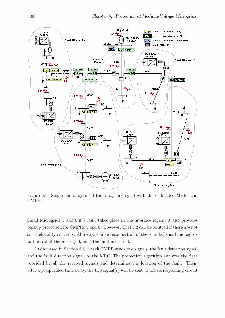
108 Chapter 5. Protection of Medium-Voltage Microgrids
Figure 5.7: Single-line diagram of the study microgrid with the embedded MPRs andCMPRs.
Small Microgrids 5 and 6 if a fault takes place in the interface region; it also provides
backup protection for CMPRs 5 and 6. However, CMPR2 can be omitted if there are not
such reliability concerns. All relays enable reconnection of the islanded small microgrids
to the rest of the microgrid, once the fault is cleared.
As discussed in Section 5.5.1, each CMPR sends two signals, the fault detection signal
and the fault direction signal, to the MPC. The protection algorithm analyzes the data
provided by all the received signals and determines the location of the fault. Then,
after a prespecified time delay, the trip signal(s) will be sent to the corresponding circuit
5.6. Design Example 109
Table 5.1: Logics for Detecting and Isolating a Fault within the Study Microgrid
Fault Oper. D1 D2 D3 D4 D5 D6 FDt Main Backup
Loc. Mode CBs CBs
IR 1 GC 2 1 0 0 0 0 0 1 CB1 Grid CB(s)
Isld 3 N/A 0 0 0 0 0 1 CB2 CB5 & CB6
CB3 CB4
SMG3 4 GC 1 0 1 0 0 0 1 CB3 CB2 (& CB1)
Isld N/A 0 1 0 0 0 1 CB4 N/A
SMG4 GC 1 0 1 1 0 0 1 CB4 CB3
Isd N/A 0 1 1 0 0 1
SMG5 GC 1 1 0 0 1 0 1 CB5 CB2 & CB6
Isld N/A 1 0 0 1 0 1
SMG6 GC 1 1 0 0 0 1 1 CB6 CB2 & CB5
Isld N/A 1 0 0 0 1 1
UG 5 GC 0 0 0 0 0 0 1 CB1 CB2 & CB3
Isld N/A N/A N/A N/A N/A N/A N/A
1. IR: Interface Region 2. GC: Grid-Connected mode 3. Isld: Islanded mode
4. SMG: Small MicroGrid 5. UG: Utility Grid
breaker(s) to isolate the impacted part of the network. Table 5.1 reports the logics that
are used to detect and isolate faults within the study microgrid. Di denotes the output
of the directional element of the ith CMPR, and FDt is the logical OR combination of
all fault detection signals sent by the CMPRs. The table also indicates the main and
backup circuit breakers, for the case of a circuit breaker failure. It should be pointed out
that a fault is considered to be a forward fault if FD=1 and D=1. For the islanded mode
of operation, relay CMPR1 does not take part in the protection task as its corresponding
circuit breaker is open for that mode of operation. Fig. 5.7 further shows that a number
of MPRs have been employed for each small microgrid to provide protection in case that
the small microgrid gets islanded; thus, the strategy (ii) of Section 5.5.1 has been adopted
to deal with permanent faults.
Fig. 5.8 illustrates the definite-time grading of the MPRs/CMPRs for the backup
protection strategy, where tf + ptm and tf + (p + q)tm respectively denote the relay
forward and reverse definite time delays (p and q are positive integers). It is noted
that the reverse definite time delay is larger than its forward counterpart, by a suitable
grading margin, q tm. Such a grading strategy can also ensure the coordination of MPRs
within a small microgrid, even if it is isolated form the rest of the network through
the operation of the circuit breakers commanded by the CMPRs. As also evident from
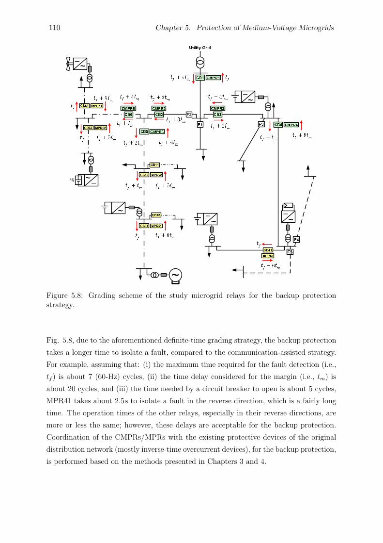
110 Chapter 5. Protection of Medium-Voltage Microgrids
Figure 5.8: Grading scheme of the study microgrid relays for the backup protectionstrategy.
Fig. 5.8, due to the aforementioned definite-time grading strategy, the backup protection
takes a longer time to isolate a fault, compared to the communication-assisted strategy.
For example, assuming that: (i) the maximum time required for the fault detection (i.e.,
tf ) is about 7 (60-Hz) cycles, (ii) the time delay considered for the margin (i.e., tm) is
about 20 cycles, and (iii) the time needed by a circuit breaker to open is about 5 cycles,
MPR41 takes about 2.5s to isolate a fault in the reverse direction, which is a fairly long
time. The operation times of the other relays, especially in their reverse directions, are
more or less the same; however, these delays are acceptable for the backup protection.
Coordination of the CMPRs/MPRs with the existing protective devices of the original
distribution network (mostly inverse-time overcurrent devices), for the backup protection,
is performed based on the methods presented in Chapters 3 and 4.
5.7. Study Cases and Simulation Results 111
5.7 Study Cases and Simulation Results
To evaluate the effectiveness of the proposed protection strategy and its CMPRs/MPRs, a
detailed model of the study microgrid has been constructed in the PSCAD/EMTDC soft-
ware environment, and study cases are simulated. For the simulations, the CMPR/MPR
settings and time delays have been calculated based on the discussion of Sections 5.5.1,
5.5.2, and 5.6. Fuses and traditional relaying functions are modeled based on the an-
alytical equations presented in Appendix B. The simulations include faults at various
locations of the study microgrid; the fault types include single phase-to-ground faults,
double phase-to-ground faults, phase-to-phase faults, three-phase-to-ground faults, and
high-impedance faults (HIFs).
HIFs are modeled in this study based on the method presented in [62]. Most re-
searchers use a 40-Ω resistance, as the maximum reasonable resistance, between a fallen
conductor and the ground; this value is also assumed by many utilities [115]. In this
chapter, however, a 100-Ω resistance has been assumed for HIFs, to simulate a more
severe condition. Further, circuit breaker and communication link failures have been
simulated to test the efficacy of the backup protection strategy.
5.7.1 Islanded Mode of Operation
Let us assume that a fault impacts the study microgrid in the islanded mode of operation.
Tables 5.2 and 5.3 report the main and backup relay operating times for a selected number
of fault scenarios. In the presented simulation results, we have tried to be as judicious
as possible in covering different types of faults, different locations, and different fault
resistances. For example, Table 5.2 shows the simulation results for solid faults while
the results of Table 5.3 corresponds to HIFs. Since in the islanded mode of operation
a fault results in a small fault current, the network fuses take a relatively long time to
isolate the fault. Therefore, the faults are first isolated by the CMPRs, through the
communication-assisted strategy. Even if the communication network fails to operate,
the CMPRs/MPRs will operate based on the backup protection strategy.
For solid faults, the voltage drop across the microgrid is significant, and the under-
voltage protection function can detect the faults. However, for HIFs, only the sequence-
component-based protection function (fault ratio in the islanded-mode protection module
of Fig. 5.3) operates, as no voltage dip is detected by the undervoltage relays.
112 Chapter 5. Protection of Medium-Voltage Microgrids
5.7.2 Grid-Connected Mode of Operation
Several cases have also been simulated for the grid-connected mode of operation but, due
to space limitations, the results of only a limited number of them have been reported
in Tables 5.4 and 5.5. The tables indicates the main and backup relay operating times
for different internal and external faults, at various locations. It is observed that if a
CMPR/MPR responsible for the main protection fails to operate, other CMPRs/MPRs
provide suitable backup protection. Again, coordination is performed in such a way that
smallest part of the faulted microgrid is de-energized in response to a fault incident.
As discussed in Section 5.5.1, the communication-assisted protection strategy sends
the trip signals after a prespecified time delay from the fault inception, to give a chance
to temporary faults to self clear or to first allow downstream protective devices to isolate
the fault. For example, it can be observed from Tables 5.2 and 5.3 that for a phase-to-
ground (AG) fault at location F54, relay MPR51 operates and isolates the fault before
CMPR5 intervenes through the communication-assisted strategy. It can also be seen in
Table 5.4 that for an AG fault at location F12, Fuse F1 breaks the fault current before
CMPR1, CMPR2, and CMPR3 operates. Therefore, for some fault scenarios, the existing
protective devices of the distribution network may operate before the communication-
assisted (main) protection strategy, in order to isolate the smallest possible area of the
faulted microgrid.
5.8 Summary and Conclusion
In this chapter, a communication-assisted protection strategy was proposed for protec-
tion of inverter-based medium-voltage microgrids. Also, a backup protection strategy
was proposed to handle communication network failures. The communication-assisted
and backup protection algorithms can be embedded into programmable microprocessor-
based relays with directional elements and are effective in both modes of operation. The
effectiveness of the proposed scheme, which does not require adaptive protective devices,
is to a large extent independent of the fault current levels, the mode of operation, and
the type and size of the microgrid DERs. Several study cases were presented based on
time-domain simulation of a sample MV microgrid, to demonstrate the effectiveness of
the proposed protection strategy and its enabling relay. The following chapter looks into
the operation of an existing distribution network as a microgrid.

5.8. Summary and Conclusion 113
Table 5.2: Operating Times of Main and Backup Protections for Selected Solid FaultScenarios in the Islanded Mode of Operation
Fault Fault Solid Faults
Type Loc. Communication-Assisted Protection Backup
Main CB Failure Protection
Oper. Oper. Oper. Oper. Oper. Oper.
Relay Time(s) Relay Time(s) Relay Time(s)
AG F11 CMPR2 0.123 CMPR4 0.473 CMPR2 1.483
CMPR3 0.123 CMPR5 0.473 CMPR3 1.816
CMPR6 0.473 CMPR4 2.158
CMPR5 1.817
CMPR6 1.817
F31 CMPR3 0.125 CMPR2 0.475 CMPR3 1.152
CMPR4 0.125 CMPR2 1.487
CMPR4 2.158
MPR41 2.484
F41 CMPR4 0.125 CMPR3 0.475 CMPR4 0.819
CMPR3 1.154
MPR41 2.487
F54 CMPR5 0.126 CMPR2 0.476 MPR51 0.084
CMPR6 0.476 MPR52 0.419
CMPR5 1.159
F61 CMPR6 0.122 CMPR2 0.472 CMPR6 0.818
CMPR5 0.472 CMPR2 1.503
CMPR5 1.821
MPR61 2.153
MPR62 2.153
BCG F62 CMPR6 0.122 CMPR2 0.472 MPR62 0.083
CMPR5 0.472 CMPR6 0.819
MPR61 2.155
F42 CMPR4 0.124 CMPR3 0.474 CMPR4 0.822
CMPR3 1.152
MPR41 2.487
BC F51 CMPR5 0.122 CMPR2 0.472 CMPR5 1.162
CMPR6 0.472 CMPR2 1.503
CMPR6 1.820
MPR52 2.157
ABC F12 CMPR2 0.123 CMPR4 0.473 CMPR2 1.483
CMPR3 0.123 CMPR5 0.473 CMPR3 1.817
CMPR6 0.473 CMPR4 2.151
CMPR5 1.817
CMPR6 1.817

114 Chapter 5. Protection of Medium-Voltage Microgrids
Table 5.3: Operating Times of Main and Backup Protections for Selected High-Impedance Fault Scenarios in the Islanded Mode of Operation
Fault Fault High-Impedance Faults (100Ω)
Type Loc. Communication-Assisted Protection Backup
Main CB Failure Protection
Oper. Oper. Oper. Oper. Oper. Oper.
Relay Time(s) Relay Time(s) Relay Time(s)
AG F11 CMPR2 0.129 CMPR4 0.479 CMPR2 1.496
CMPR3 0.129 CMPR5 0.479 CMPR3 1.833
CMPR6 0.479 CMPR4 2.189
CMPR5 1.830
CMPR6 1.830
F31 CMPR3 0.128 CMPR2 0.478 CMPR3 1.171
CMPR4 0.128 CMPR2 1.495
CMPR4 2.172
MPR41 2.499
F41 CMPR4 0.136 CMPR3 0.486 CMPR4 0.847
CMPR3 1.203
MPR41 2.491
F54 CMPR5 0.131 CMPR2 0.481 MPR51 0.096
CMPR6 0.481 MPR52 0.431
CMPR5 1.217
F61 CMPR6 0.125 CMPR2 0.475 CMPR6 0.833
CMPR5 0.475 CMPR2 1.516
CMPR5 1.834
MPR61 2.176
MPR62 2.176
BCG F62 CMPR6 0.125 CMPR2 0.475 MPR62 0.097
CMPR5 0.475 CMPR6 0.838
MPR61 2.184
F42 CMPR4 0.127 CMPR3 0.477 CMPR4 0.850
CMPR3 1.171
MPR41 2.511
BC F51 CMPR5 0.125 CMPR2 0.475 CMPR5 1.200
CMPR6 0.475 CMPR2 1.515
CMPR6 1.831
MPR52 2.199
ABC F12 N/A
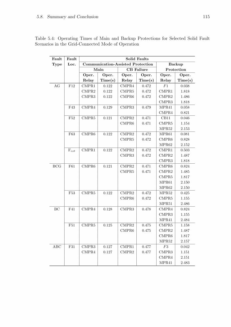
5.8. Summary and Conclusion 115
Table 5.4: Operating Times of Main and Backup Protections for Selected Solid FaultScenarios in the Grid-Connected Mode of Operation
Fault Fault Solid Faults
Type Loc. Communication-Assisted Protection Backup
Main CB Failure Protection
Oper. Oper. Oper. Oper. Oper. Oper.
Relay Time(s) Relay Time(s) Relay Time(s)
AG F12 CMPR1 0.122 CMPR4 0.472 F1 0.038
CMPR2 0.122 CMPR5 0.472 CMPR1 1.818
CMPR3 0.122 CMPR6 0.472 CMPR2 1.486
CMPR3 1.818
F43 CMPR4 0.129 CMPR3 0.479 MPR41 0.058
CMPR4 0.821
F52 CMPR5 0.121 CMPR2 0.471 CB11 0.046
CMPR6 0.471 CMPR5 1.154
MPR52 2.153
F63 CMPR6 0.122 CMPR2 0.472 MPR61 0.081
CMPR5 0.472 CMPR6 0.828
MPR62 2.152
Fext CMPR1 0.122 CMPR2 0.472 CMPR1 0.503
CMPR3 0.472 CMPR2 1.487
CMPR3 1.818
BCG F61 CMPR6 0.121 CMPR2 0.471 CMPR6 0.824
CMPR5 0.471 CMPR2 1.485
CMPR5 1.817
MPR61 2.150
MPR62 2.150
F53 CMPR5 0.122 CMPR2 0.472 MPR52 0.425
CMPR6 0.472 CMPR5 1.155
MPR51 2.486
BC F41 CMPR4 0.128 CMPR3 0.478 CMPR4 0.824
CMPR3 1.155
MPR41 2.484
F51 CMPR5 0.125 CMPR2 0.475 CMPR5 1.158
CMPR6 0.475 CMPR2 1.487
CMPR6 1.817
MPR52 2.157
ABC F31 CMPR3 0.127 CMPR1 0.477 F3 0.042
CMPR4 0.127 CMPR2 0.477 CMPR3 1.151
CMPR4 2.151
MPR41 2.483

116 Chapter 5. Protection of Medium-Voltage Microgrids
Table 5.5: Operating Times of Main and Backup Protections for Selected High-Impedance Fault Scenarios in the Grid-Connected Mode of Operation
Fault Fault High-Impedance Faults (100Ω)
Type Loc. Communication-Assisted Protection Backup
Main CB Failure Protection
Oper. Oper. Oper. Oper. Oper. Oper.
Relay Time(s) Relay Time(s) Relay Time(s)
AG F12 CMPR1 0.128 CMPR4 0.478 CMPR1 1.831
CMPR2 0.128 CMPR5 0.478 CMPR2 1.492
CMPR3 0.128 CMPR6 0.478 CMPR3 1.835
F43 CMPR4 0.137 CMPR3 0.487 MPR41 0.097
CMPR4 0.848
F52 CMPR5 0.122 CMPR2 0.472 CMPR5 1.190
CMPR6 0.472 CMPR2 1.502
CMPR6 1.840
MPR52 2.160
F63 CMPR6 0.122 CMPR2 0.472 MPR61 0.106
CMPR5 0.472 CMPR6 0.852
MPR62 2.164
Fext CMPR1 0.134 CMPR2 0.484 CMPR1 0.509
CMPR3 0.484 CMPR2 1.493
CMPR3 1.824
BCG F61 CMPR6 0.123 CMPR2 0.473 CMPR6 0.857
CMPR5 0.473 CMPR2 1.503
CMPR5 1.832
MPR61 2.159
MPR62 2.159
F53 CMPR5 0.123 CMPR2 0.473 MPR52 0.436
CMPR6 0.473 CMPR5 1.159
MPR51 2.495
BC F41 CMPR4 0.130 CMPR3 0.480 CMPR4 0.838
CMPR3 1.162
MPR41 2.508
F51 CMPR5 0.127 CMPR2 0.477 CMPR5 1.164
CMPR6 0.477 CMPR2 1.507
CMPR6 1.842
MPR52 2.167
ABC F31 N/A
Chapter 6
Operation of an Existing
Distribution Network as a Microgrid
6.1 Introduction
With the increasing attention to the concept of microgrid, it has become important to
identify the requirements that enable an existing electric distribution network to operate
as a microgrid. In this chapter, a Canadian utility distribution network embedding DERs
is studied with the first objective of determining the conditions under which the network
can operate as a microgrid in both the grid-connected and islanded modes. The likelihood
of operation of the distribution network in isolation from the utility grid is investigated,
and (minimal) required changes for the control of the islanded network are discussed.
Two of the possible options, i.e., (i) the addition of a conventional dispatchable DER to
the distribution network and (ii) the addition of an integrated energy storage device to
the existing network, are investigated, and the control scenarios that could enable the
network to operate in the islanded mode are presented; the optimal solution can then
be selected based on the system limitations/constraints. Moreover, the possibilities and
requirements for the reconnection of the islanded system to the main utility grid when
the grid fault is cleared are studied.
The second objective of the chapter is to devise practical and appropriate protection
strategies that are effective in the grid-connected as well as the islanded mode of opera-
tion. The protection strategies aim to provide the microgrid with acceptable reliability
against various types of faults, at different locations and during different operational
conditions; the best option is, however, chosen based on the system requirements and
117
118 Chapter 6. Operation of an Existing Distribution Network as a Microgrid
constraints. The effectiveness of the proposed control and protection strategies is demon-
strated through a comprehensive set of simulation studies on a detailed model of a realistic
distribution network, in the PSCAD/EMTDC software environment.
6.2 Study System
As mentioned in Section 6.1, a realistic distribution network is studied in this chapter
to identify the changes required for the microgrid operation of an existing network. In
other words, control and protection scenarios presented in this chapter are discussed
and explained in the context of a “study system”, which is introduced in this section;
this, however, does not compromise the generality of the presented methodologies and
discussions. Fig. 6.1 shows a simplified single-line schematic diagram of a Canadian radial
distribution network that is used to investigate typical microgrid operational scenarios.
The radial network is connected to the utility grid through a 115/27.6-kV transmission
substation, and includes a capacitor bank on its main feeder in addition to a circuit
breaker with an automatic reclosing mechanism. The network has single- and three-
phase loads and a variety of transformers at different voltage levels; the transformers are
distributed along the main feeder (with a total length of 40km) and the laterals. The
main feeder autorecloser is set to operate in the fast and slow modes [52], in a coordinated
way. It is assumed that a DER unit is installed 15km away from the main circuit breaker.
This DER is interfaced with the grid at the Point of Common Coupling (PCC) through
a ∆/GY transformer, as indicated in Fig. 6.1. The distribution feeders are modeled by
Π sections along with all of its loading details.
6.3 Microgrid Formation due to Islanding
As discussed in Chapter 1, a microgrid is a portion of a distribution network that possesses
enough generation (one or more DERs) such that it can continue to operate even if it
is disconnected from the upstream utility grid. In the context of the study system of
Fig. 6.1, the 27.6-kV distribution system, including the loads and the DER, constitutes
a microgrid. Fig. 6.1 also illustrates the electrical boundary where the isolation and
reconnection with the grid can take place. The microgrid can be isolated from the main
grid by the operation of a circuit breaker that is located at the medium-voltage side
of the substation transformer. In this chapter, this circuit breaker is referred to as the
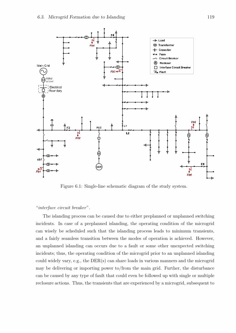
6.3. Microgrid Formation due to Islanding 119
Figure 6.1: Single-line schematic diagram of the study system.
“interface circuit breaker”.
The islanding process can be caused due to either preplanned or unplanned switching
incidents. In case of a preplanned islanding, the operating condition of the microgrid
can wisely be scheduled such that the islanding process leads to minimum transients,
and a fairly seamless transition between the modes of operation is achieved. However,
an unplanned islanding can occurs due to a fault or some other unexpected switching
incidents; thus, the operating condition of the microgrid prior to an unplanned islanding
could widely vary, e.g., the DER(s) can share loads in various manners and the microgrid
may be delivering or importing power to/from the main grid. Further, the disturbance
can be caused by any type of fault that could even be followed up with single or multiple
reclosure actions. Thus, the transients that are experienced by a microgrid, subsequent to
120 Chapter 6. Operation of an Existing Distribution Network as a Microgrid
an unplanned islanding process, is dependent on several factor such as (i) pre-islanding
operating conditions, (ii) type, location, and severity of the fault, (iii) fault clearing
time, (iv) post-fault switching actions, and (v) type of the DER(s) employed in the
microgrid [51]. In this chapter, which is mainly focused on the unplanned islanding, it is
investigated how some of these factors can affect the microgrid performance in different
control scenarios.
Once the microgrid is islanded, it should be able to continue safe operation till the fault
is cleared and the microgrid can reconnect to the utility grid. Therefore, a synchronization
process is also necessary prior to reconnecting an islanded microgrid to the upstream grid.
The voltage phasors at the microgrid and utility sides of the interface circuit breaker must
be aligned, and their magnitude must be made equal, to ensure that the voltage across
the circuit breaker is reasonably small; the reconnection can proceed if the voltage has
had a sufficiently small magnitude, for an adequately large time [76]. For example, for a
microgrid with DERs in the range of 1.5 to 10MW, reconnection is acceptable if voltage
error is below 3%, frequency error is below 0.1Hz, and phase-angle error is below 10 [76].
Adhering to these limits ensures that the reconnection of the microgrid to the main utility
grid be achieved with minimal transients in the overall system.
6.4 Operation as a Microgrid: Control
6.4.1 Scenario 1: Conventional DER(s)
The first possible scenario is to connect a conventional rotating-machine-based DER to
the distribution network at the PCC. For the system of Fig. 6.1, the maximum load is 3.5
MVA, and it is assumed that a 5-MVA synchronous generator is connected to the network
at the PCC. For this scenario, the DER is modeled as a single-mass synchronous machine
with two rotor windings on each axis [116]; the excitation and governor systems are also
included in the machine model. The electrical parameters of the machine, represented in a
rotating dq frame, are reported in Appendix E. Considering the fault rate and repair time
in a North-American distribution system [117]-[120], the use of a synchronous-machine-
based DER is an economical solution for making a temporary island. For the period of
time that the fault is being taken care of, this solution can effectively work and make
the system to operate in the islanded mode. The use of conventional DERs has such
advantages as simple, well-known, and inexpensive control system; and independence of
the environmental conditions.
6.4. Operation as a Microgrid: Control 121
Requirements for the Islanded Mode of Operation: In the grid-connected mode of
operation, the DERs are controlled in a constant-power mode meaning that they deliver
a pre-specified constant active/reactive power to the distribution network. As such, the
host grid offsets the provided power by the DERs, i.e., the utility grid absorbs/injects
power from/to the distribution network. In the islanded mode of operation, however, the
entire microgrid should only be energized by the DER(s). Therefore, the DER must at
least meet the two following requirements: (i) the DER must be dispatchable such that
it can follow and fulfil the load demand. Therefore, as also mentioned in the previous
section, the machine is equipped with the excitation and governor systems such that it
can adjust its output power once the microgrid gets islanded. The voltage and frequency
setpoints of the excitation and governor systems are determined based on the well-known
droop strategy; the technique is similar to what is done in large power-generation plants
and does not require any communications. (ii) the DER must have enough capacity
to satisfy the maximum demand of the islanded microgrid; otherwise, a load-shading
scheme1 must also be utilized for the islanded network. It is worth mentioning that a
rotating-machine-based DER may employ a steam turbine, a gas turbine, a hydro turbine,
or an internal combustion engine, depending on the available resources (biomass, natural
gas, water, diesel fuel, etc.).
Despite the advantages of the conventional rotating-machine-based DERs, they cause
serious issues in the electric power system among them high noises, fuel storage require-
ments, engine maintenance, and greenhouse gas emission. Moreover, due to the relatively
slow dynamic response of the conventional DERs, the system response to fault incidents
and transient disturbances is significantly affected, which may not be acceptable for some
local distribution networks. Considering the abovementioned drawbacks, the use of re-
newable energy systems in electric power networks has attracted a considerable attention,
as will be discussed in the following section.
6.4.2 Scenario 2: Electronically Coupled DER(s)
Recently, due to the environmental concerns and depletion of fossil fuel reserves, the
deployment of renewable energy systems has rapidly increased. Renewable energy re-
sources are clean, safe, and sustainable; and require less maintenance than traditional
generators. Amongst the renewable energy resources, wind power is an environmentally
attractive form, from an overall fuel consumption perspective. Currently, wind power is
1Load-shading algorithms are not discussed in the thesis, as they are beyond the scope of this study.
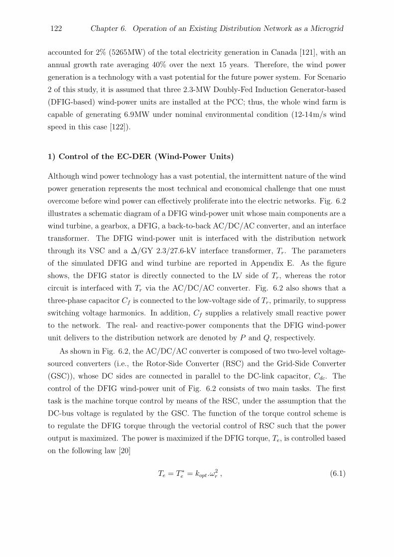
122 Chapter 6. Operation of an Existing Distribution Network as a Microgrid
accounted for 2% (5265MW) of the total electricity generation in Canada [121], with an
annual growth rate averaging 40% over the next 15 years. Therefore, the wind power
generation is a technology with a vast potential for the future power system. For Scenario
2 of this study, it is assumed that three 2.3-MW Doubly-Fed Induction Generator-based
(DFIG-based) wind-power units are installed at the PCC; thus, the whole wind farm is
capable of generating 6.9MW under nominal environmental condition (12-14m/s wind
speed in this case [122]).
1) Control of the EC-DER (Wind-Power Units)
Although wind power technology has a vast potential, the intermittent nature of the wind
power generation represents the most technical and economical challenge that one must
overcome before wind power can effectively proliferate into the electric networks. Fig. 6.2
illustrates a schematic diagram of a DFIG wind-power unit whose main components are a
wind turbine, a gearbox, a DFIG, a back-to-back AC/DC/AC converter, and an interface
transformer. The DFIG wind-power unit is interfaced with the distribution network
through its VSC and a ∆/GY 2.3/27.6-kV interface transformer, Tr. The parameters
of the simulated DFIG and wind turbine are reported in Appendix E. As the figure
shows, the DFIG stator is directly connected to the LV side of Tr, whereas the rotor
circuit is interfaced with Tr via the AC/DC/AC converter. Fig. 6.2 also shows that a
three-phase capacitor Cf is connected to the low-voltage side of Tr, primarily, to suppress
switching voltage harmonics. In addition, Cf supplies a relatively small reactive power
to the network. The real- and reactive-power components that the DFIG wind-power
unit delivers to the distribution network are denoted by P and Q, respectively.
As shown in Fig. 6.2, the AC/DC/AC converter is composed of two two-level voltage-
sourced converters (i.e., the Rotor-Side Converter (RSC) and the Grid-Side Converter
(GSC)), whose DC sides are connected in parallel to the DC-link capacitor, Cdc. The
control of the DFIG wind-power unit of Fig. 6.2 consists of two main tasks. The first
task is the machine torque control by means of the RSC, under the assumption that the
DC-bus voltage is regulated by the GSC. The function of the torque control scheme is
to regulate the DFIG torque through the vectorial control of RSC such that the power
output is maximized. The power is maximized if the DFIG torque, Te, is controlled based
on the following law [20]
Te = T ∗e = kopt.ω
2r , (6.1)
6.4. Operation as a Microgrid: Control 123
Figure 6.2: Schematic diagram of a DFIG wind-power unit.
where T ∗e is the reference value for the machine torque, ωr denotes the DFIG shaft speed,
and kopt is a proportionality constant.
The second control task of the DFIG wind-power unit is the DC-link voltage/reactive-
power regulation by means of the GSC. In the wind-power unit of Fig. 6.2, the DC-
link voltage is maintained in its reference value, V ∗dc, through the control of real-power
component of the GSC, i.e., Pgs (see also Fig. 1.6). The reactive-power component Qgs
is also controlled by the GSC to regulate the PCC voltage level. The two control tasks
(i.e., the torque control and the DC-link voltage control) are independent of each other
and thus treated separately. The details of the wind-power unit control schemes, which
are performed in a dq reference frame, can be found in reference [20].
Requirements for the Islanded Mode of Operation: To operate the network of
Fig. 6.1 as an islanded microgrid, a fine balance must be obtained between the wind-
power generation and the total network power demand. This, however, is very difficult, if
not impossible, to achieve due to the time-varying nature of the wind energy. Therefore,
the islanded network must also embed a dispatchable (and adequately fast) DER to
compensate for the mismatch between the wind and load powers.
A dispatchable DER may again be realized through rotating-machine-based DERs.
However, conventional rotating machines are rather slow for compensation of fast power
fluctuations (due to wind speed fluctuations). Therefore, the wind farm may need to
124 Chapter 6. Operation of an Existing Distribution Network as a Microgrid
be augmented by faster dispatchable DERs such as fuel cells and/or Battery Energy
Storage Systems (BESSs). While fuel cells are still facing technical challenges, batteries
represent a relatively well-established and proven technology which is gaining even further
momentum due to the transportation industry initiatives. Moreover, BESSs do not
require any fuel storage; they can be recharged and thus offer more operational flexibility.
Furthermore, integrating a BESS with a wind farm can smooth out the intermittent power
from the wind farm [11]. In this chapter, a BESS is assumed to be the dispatchable DER
of the microgrid for Scenario 2, but it is understood that the absence of a rotating-
machine-based dispatchable DER may translate into a fairly large BESS.
The BESS is assumed to consist of a bank of lead-acid batteries; As Fig. 6.3 shows, the
BESS is interfaced with the microgrid by means of a three-phase VSC and its three-phase
low-pass LC filter; the whole dispatchable DER is connected to the network at a point of
common coupling close to the electrical boundary (PCC1), through an interconnection
transformer (see Fig. 6.3). The reason why this location has been selected for the
connection of the BESS to the network is to facilitate the synchronization process (the
synchronization algorithm will be discussed later in the text). However, if there are
communication facilities available, the point where the wind farm is interfaced with the
network (PCC) is the best option for the BESS interface point.
The VSC of the BESS is employed to control the rate of charge/discharge of the BESS.
Since the average wind speed in the region under study is about 7.6m/s [123], a 3-MVA
VSC would be a good choice considering smooth wind speed changes around the average
value for most of the time. Moreover, with regard to the average repair/replacement time
in a typical distribution system [119], the BESS size is considered to be 10MWh. Such a
BESS can be build by taking the individual lead-acid batteries in series and parallel to
get the desired voltage and energy ratings. For example, to realize the 10-MWh BESS
with a DC voltage of 1.5kV (chosen to facilitate the VSC design), we need to connect
702 lead-acid batteries of 2.135V in series to get the desired voltage, and connect ten of
these series strings in parallel to obtain the desired energy rating, which results in a total
number of 7020 batteries [11].
2) Control of the BESS
A multimode control strategy can be adopted for a DFIG wind-power unit augmented
with an energy storage device, to enable operation in the islanded mode as well as the
grid-connected mode [124]. This control strategy, however, is suitable for small off-grid
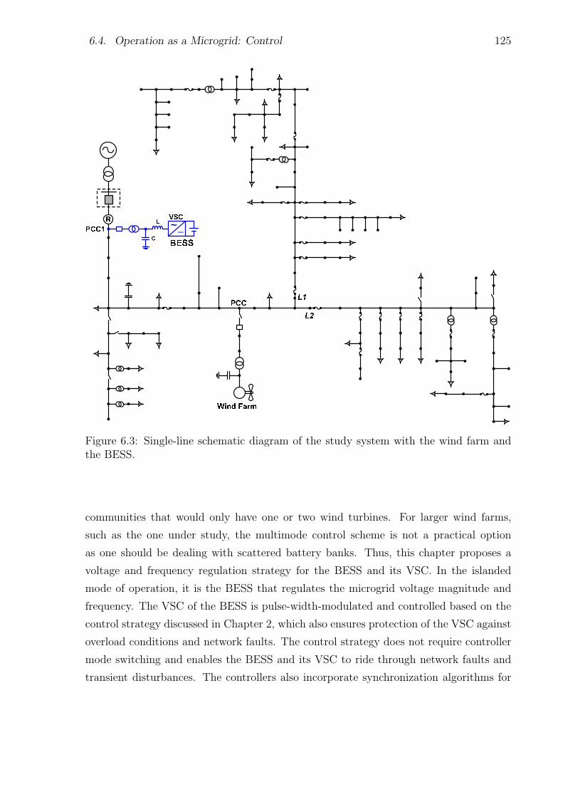
6.4. Operation as a Microgrid: Control 125
Figure 6.3: Single-line schematic diagram of the study system with the wind farm andthe BESS.
communities that would only have one or two wind turbines. For larger wind farms,
such as the one under study, the multimode control scheme is not a practical option
as one should be dealing with scattered battery banks. Thus, this chapter proposes a
voltage and frequency regulation strategy for the BESS and its VSC. In the islanded
mode of operation, it is the BESS that regulates the microgrid voltage magnitude and
frequency. The VSC of the BESS is pulse-width-modulated and controlled based on the
control strategy discussed in Chapter 2, which also ensures protection of the VSC against
overload conditions and network faults. The control strategy does not require controller
mode switching and enables the BESS and its VSC to ride through network faults and
transient disturbances. The controllers also incorporate synchronization algorithms for
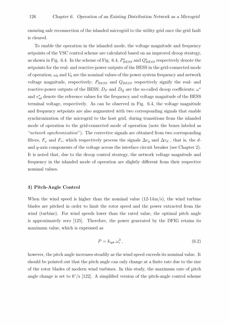
126 Chapter 6. Operation of an Existing Distribution Network as a Microgrid
ensuring safe reconnection of the islanded microgrid to the utility grid once the grid fault
is cleared.
To enable the operation in the islanded mode, the voltage magnitude and frequency
setpoints of the VSC control scheme are calculated based on an improved droop strategy,
as shown in Fig. 6.4. In the scheme of Fig. 6.4, P ∗BESS and Q∗
BESS respectively denote the
setpoints for the real- and reactive-power outputs of the BESS in the grid-connected mode
of operation; ω0 and V0 are the nominal values of the power system frequency and network
voltage magnitude, respectively; PBESS and QBESS respectively signify the real- and
reactive-power outputs of the BESS; DP and DQ are the so-called droop coefficients; ω∗
and v∗sd denote the reference values for the frequency and voltage magnitude of the BESS
terminal voltage, respectively. As can be observed in Fig. 6.4, the voltage magnitude
and frequency setpoints are also augmented with two corresponding signals that enable
synchronization of the microgrid to the host grid, during transitions from the islanded
mode of operation to the grid-connected mode of operation (note the boxes labeled as
“network synchronization”). The corrective signals are obtained from two corresponding
filters, Fω and Fv, which respectively process the signals ∆vq and ∆vd , that is, the d-
and q-axis components of the voltage across the interface circuit breaker (see Chapter 2).
It is noted that, due to the droop control strategy, the network voltage magnitude and
frequency in the islanded mode of operation are slightly different from their respective
nominal values.
3) Pitch-Angle Control
When the wind speed is higher than the nominal value (12-14m/s), the wind turbine
blades are pitched in order to limit the rotor speed and the power extracted from the
wind (turbine). For wind speeds lower than the rated value, the optimal pitch angle
is approximately zero [125]. Therefore, the power generated by the DFIG retains its
maximum value, which is expressed as
P = kopt.ω3r , (6.2)
however, the pitch angle increases steadily as the wind speed exceeds its nominal value. It
should be pointed out that the pitch angle can only change at a finite rate due to the size
of the rotor blades of modern wind turbines. In this study, the maximum rate of pitch
angle change is set to 6/s [122]. A simplified version of the pitch-angle control scheme
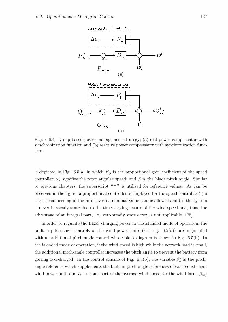
6.4. Operation as a Microgrid: Control 127
Figure 6.4: Droop-based power management strategy; (a) real power compensator withsynchronization function and (b) reactive power compensator with synchronization func-tion.
is depicted in Fig. 6.5(a) in which Kp is the proportional gain coefficient of the speed
controller; ωr signifies the rotor angular speed; and β is the blade pitch angle. Similar
to previous chapters, the superscript “ * ” is utilized for reference values. As can be
observed in the figure, a proportional controller is employed for the speed control as (i) a
slight overspeeding of the rotor over its nominal value can be allowed and (ii) the system
is never in steady state due to the time-varying nature of the wind speed and, thus, the
advantage of an integral part, i.e., zero steady state error, is not applicable [125].
In order to regulate the BESS charging power in the islanded mode of operation, the
built-in pitch-angle controls of the wind-power units (see Fig. 6.5(a)) are augmented
with an additional pitch-angle control whose block diagram is shown in Fig. 6.5(b). In
the islanded mode of operation, if the wind speed is high while the network load is small,
the additional pitch-angle controller increases the pitch angle to prevent the battery from
getting overcharged. In the control scheme of Fig. 6.5(b), the variable β∗S is the pitch-
angle reference which supplements the built-in pitch-angle references of each constituent
wind-power unit, and vW is some sort of the average wind speed for the wind farm; βref
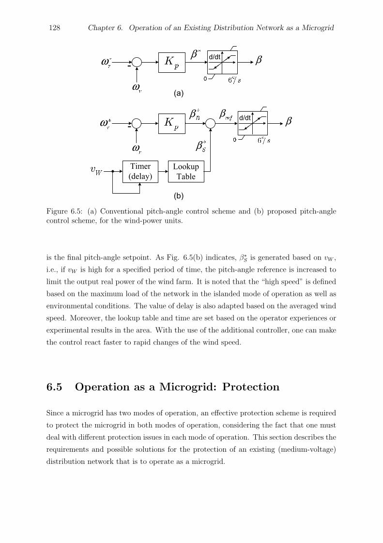
128 Chapter 6. Operation of an Existing Distribution Network as a Microgrid
Figure 6.5: (a) Conventional pitch-angle control scheme and (b) proposed pitch-anglecontrol scheme, for the wind-power units.
is the final pitch-angle setpoint. As Fig. 6.5(b) indicates, β∗S is generated based on vW ,
i.e., if vW is high for a specified period of time, the pitch-angle reference is increased to
limit the output real power of the wind farm. It is noted that the “high speed” is defined
based on the maximum load of the network in the islanded mode of operation as well as
environmental conditions. The value of delay is also adapted based on the averaged wind
speed. Moreover, the lookup table and time are set based on the operator experiences or
experimental results in the area. With the use of the additional controller, one can make
the control react faster to rapid changes of the wind speed.
6.5 Operation as a Microgrid: Protection
Since a microgrid has two modes of operation, an effective protection scheme is required
to protect the microgrid in both modes of operation, considering the fact that one must
deal with different protection issues in each mode of operation. This section describes the
requirements and possible solutions for the protection of an existing (medium-voltage)
distribution network that is to operate as a microgrid.
6.5. Operation as a Microgrid: Protection 129
6.5.1 Grid-Connected Mode of Operation
As discussed in Chapter 1, several protection issues may arise in the grid-connected
mode of operation, depending on the DER type, size, and location. One of the main
issues associated with the addition of DERs to the distribution network is recloser-fuse
miscoordination. Reference [126] has proposed a method to find the threshold value of
the DER capacity, beyond which the recloser-fuse coordination is lost. The simulations
show satisfactory results; however, the capacity of the DER is not a design option in
many practical cases. In [127], a classification technique is presented to search for the
best DER location where minimum recloser-fuse miscoordination occurs for different fault
scenarios. Although an option, the location of the DER may also be forced to the designer
in many cases. Therefore, it is necessary to come up with a technique that can retrieve
the recloser-fuse coordination while DERs are in place. In this chapter, the coordination
method proposed in Chapter 3 is adopted to coordinate the recloser and fuses in the
presence of the DERs such that the recloser always operates first, once a fault impacts
the network. To do so, the main feeder recloser should be replaced with a commercially
available microprocessor-based recloser. Then, the settings of the recloser are carefully
selected to accommodate the impacts of DERs (see Section 3.2).
It should be pointed out that the proposed coordination algorithm is employed to
coordinate the recloser with the lowest-rating fuse of the main feeder so that higher-
rating fuses (upstream fuses) are automatically coordinated with the recloser. Therefore,
when a fault strikes the network, the recloser operates first (according to its fast-mode
characteristic curve) and gives a chance to temporary faults to self clear. In case the
fault is permanent, the fuses and the recloser (in its slow mode of operation) provide
backup protection, respectively. Once the recloser of the feeder operates in response to a
fault incident, two scenarios can be considered to protect the distribution system when
the recloser recloses the circuit for the first time, and the fault does still exist. In what
follows, these scenarios are described:
1) Scenario 1: The first scenario is to disconnect the DER(s) as soon as the recloser
operates for the first time. This requires to establish some sort of communications be-
tween the recloser and the DER(s) such that the disconnection of the DER(s) can be
performed by a transfer-trip mechanism. Applying this scenario can ensure the coordi-
nation of the protective devices after the first reclosure of the recloser, as there would be
130 Chapter 6. Operation of an Existing Distribution Network as a Microgrid
no DER connected to the network to interrupt the coordination. Moreover, the issues
associated with the reconnection of two asynchronous systems, once the recloser recloses
the circuit, are resolved. However, the disadvantage is that the DER(s) get dropped out
for any transient incident or temporary fault, and the required power for the distribution
network should be provided by the utility grid during this period. In addition, establish-
ing a communication channel between the recloser and the DER(s) is translated in the
more expenses.
2) Scenario 2: The second scenario is to keep the DER(s) connected to the network,
even during the dead time of the reclosing mechanism. Adopting this strategy may,
however, compromise the coordination amongst the fuses once the recloser recloses the
circuit. To prevent fuse-fuse miscoordination in this situation, two options can be en-
visioned: (i) to replace all downstream fuses of the DER(s) with such high-rating fuses
that are coordinated under the new condition, i.e., with the existence of the DER(s);
this option, however, is both costly and time-consuming. (ii) to employ a fault current
limiter(s) (FCL) in series with the DER(s) in order to limit DER fault currents to such
low levels that the coordination issues do not manifest themselves [53], [54], [128].
In general, an FCL is a series device that is considered to be hidden to the network
(zero/low impedance) in normal operation, but takes fast action to limit the instanta-
neous magnitude of the short-circuit current to a preset value. The task is performed by
inserting a high impedance of predesigned value into the network [54]. Since FCLs limit
the fault current contribution of DERs, they can either prevent miscoordination between
the recloser and fuses or facilitate the process of recloser-fuse coordination that was de-
scribed in Section 6.5.1. However, to incorporate the transient regime of the FCLs [128],
the coordination algorithm of Chapter 3 is still employed in this study to ensure the
coordination between the recloser and the fuses. It is noted that the dead time of the
reclosing mechanism is assumed to be less than 0.5s (30 cycles) and, thus, no significant
asynchronization is generated [51]. Further, the asynchronication can be reduced through
the adoption of the control strategy of Section 6.4.2–2 (see also Chapter 2).
6.5.2 Islanded Mode of Operation
As explained in the previous chapters, fault currents are typically small in the islanded
mode of operation. Consequently, the conventional overcurrent protection is not adequate
for this mode. For an existing distribution network, three protection scenarios can be
6.5. Operation as a Microgrid: Protection 131
envisioned for the islanded mode of operation considering the likelihood of the microgrid
formation [117]- [120]. These scenarios are as the following:
1) Scenario 1: The first scenario is to preserve the existing protection scheme. Thus,
when a fault impacts the islanded microgrid, the protections of the DER(s) must detect
the fault and disconnect the DER(s), after an appropriate time delay. This means that
once a fault takes place within the islanded microgrid, the entire microgrid is shut down.
Therefore, any fault results in a service disruption in the whole microgrid and, thus, the
reliability of the system is easily compromised. Moreover, if the protections of the DER(s)
fail to operate for any reason, there will not be any remote backup protection which can
result in serious damage to the equipment. Nonetheless, considering the likelihood of the
fault occurrence for the period of time that the system is islanded [119], this simple scheme
may suffice, particularly for those microgrids that do not embed critical/sensitive loads.
However, this scenario is not studied in the chapter due to the well-known responses and
consequences.
2) Scenario 2: The second scenario is to replace some of the protective devices of the
microgrid with overcurrent relays. The overcurrent relays should, thus, be equipped with
two distinct setting groups, one for the islanded mode of operation and the other for the
grid-connected mode of operation. The settings for the grid-connected mode of operation
are determined based on the method presented in Section 6.5.1. However, in the islanded
mode of operation, a traditional protection coordination method (see Section 1.4.1) can
be employed to coordinate overcurrent relays; the only point that should be taken into
account is that one may need to use directional element(s) to prevent false tripping, in
case there are more than one DER in the microgrid; this was explained in Chapters
3 and 4. It should also be pointed out that the appropriate setting group is selected
based on the status of the interface circuit breaker. Therefore, the setting group of the
relay should change by an operator or through a communication-based method, once the
status of the interface circuit breaker changes. An anti-islanding mechanism can also be
employed along with overcurrent relays to switch the “grid-connected setting group” to
the “islanded setting group”.
3) Scenario 3: The third and last scenario is to devise a more sophisticated micropro-
cessor-based relay that embeds different protection functions and can fully protect the
132 Chapter 6. Operation of an Existing Distribution Network as a Microgrid
microgrid in both operational modes, with no need to protection mode switching. Such
a relay, which was proposed in Chapter 4, can also ensure protection against all types
of faults including high-impedance faults, and is thus expected to enhance the system
reliability. Therefore, it is necessary to replace some of the network protective devices
by the circuit breakers governed by such microprocessor-based relays. Hypothetically,
replacement of all protective devices with microprocessor-based relays is possible. How-
ever, one should replace the existing protective devices by microprocessor-based relays
based on the system requirements and constraints/limits.
For the study system of this chapter, a modified version of the relay proposed in
Chapter 4 can be employed. Fig. 6.6 illustrates the schematic diagram of the Microgrid
Protection Relay (MPR) that is employed in this chapter. The figure shows that the
proposed MPR consists of five modules: (i) the “directional module” which is respon-
sible to determine the fault direction. (ii) the “islanded module” which is supposed to
provide protection in the islanded mode of operation. As can be observed in Fig. 6.6,
under-voltage elements are employed in the islanded module as the fault currents are
relatively small in the islanded mode of operation. A current-magnitude supervision is
also employed in the module to prevent mal-operation of the MPR for the laterals with
no DERs. (iii) the “grid-connected module” which is responsible for the protection of
the network in the grid-connected mode of operation. The settings of the inverse-time
overcurrent elements of this module are specified based on the method of Section 6.5.1.
The HIF detection element is also supposed to detect high-impedance faults using the
sequence components and signal energy levels (see Chapters 4 and 5). (iv) the “interface
module” is only enabled for the relay installed at the electrical boundary; the module in-
cludes NVD and synchronism-check functions. (v) the “tripping module” finally decides
whether or not a trip signal should be issued.
Since the voltage drop caused by a fault appears more or less across the entire mi-
crogrid, directional modules may be required to obtain protection coordination. The
forward and reverse time delays are set by proper selection of TD IF, TD GF, TD IR,
and TD GR such that the coordination is achieved for both forward and revers faults; the
details of the coordination technique can be found in Chapter 4. As will be discussed in
Section 6.6.2, it is not required to use directional modules for the MPRs installed within
the study system of this chapter.
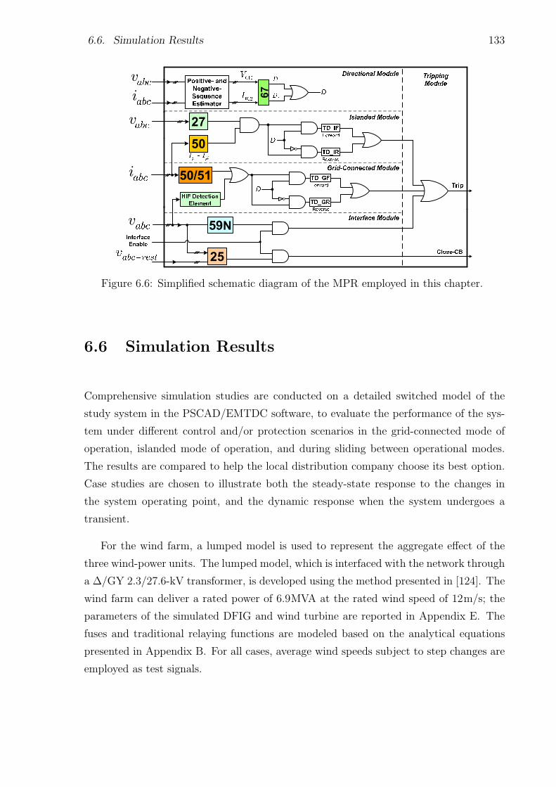
6.6. Simulation Results 133
Figure 6.6: Simplified schematic diagram of the MPR employed in this chapter.
6.6 Simulation Results
Comprehensive simulation studies are conducted on a detailed switched model of the
study system in the PSCAD/EMTDC software, to evaluate the performance of the sys-
tem under different control and/or protection scenarios in the grid-connected mode of
operation, islanded mode of operation, and during sliding between operational modes.
The results are compared to help the local distribution company choose its best option.
Case studies are chosen to illustrate both the steady-state response to the changes in
the system operating point, and the dynamic response when the system undergoes a
transient.
For the wind farm, a lumped model is used to represent the aggregate effect of the
three wind-power units. The lumped model, which is interfaced with the network through
a ∆/GY 2.3/27.6-kV transformer, is developed using the method presented in [124]. The
wind farm can deliver a rated power of 6.9MVA at the rated wind speed of 12m/s; the
parameters of the simulated DFIG and wind turbine are reported in Appendix E. The
fuses and traditional relaying functions are modeled based on the analytical equations
presented in Appendix B. For all cases, average wind speeds subject to step changes are
employed as test signals.
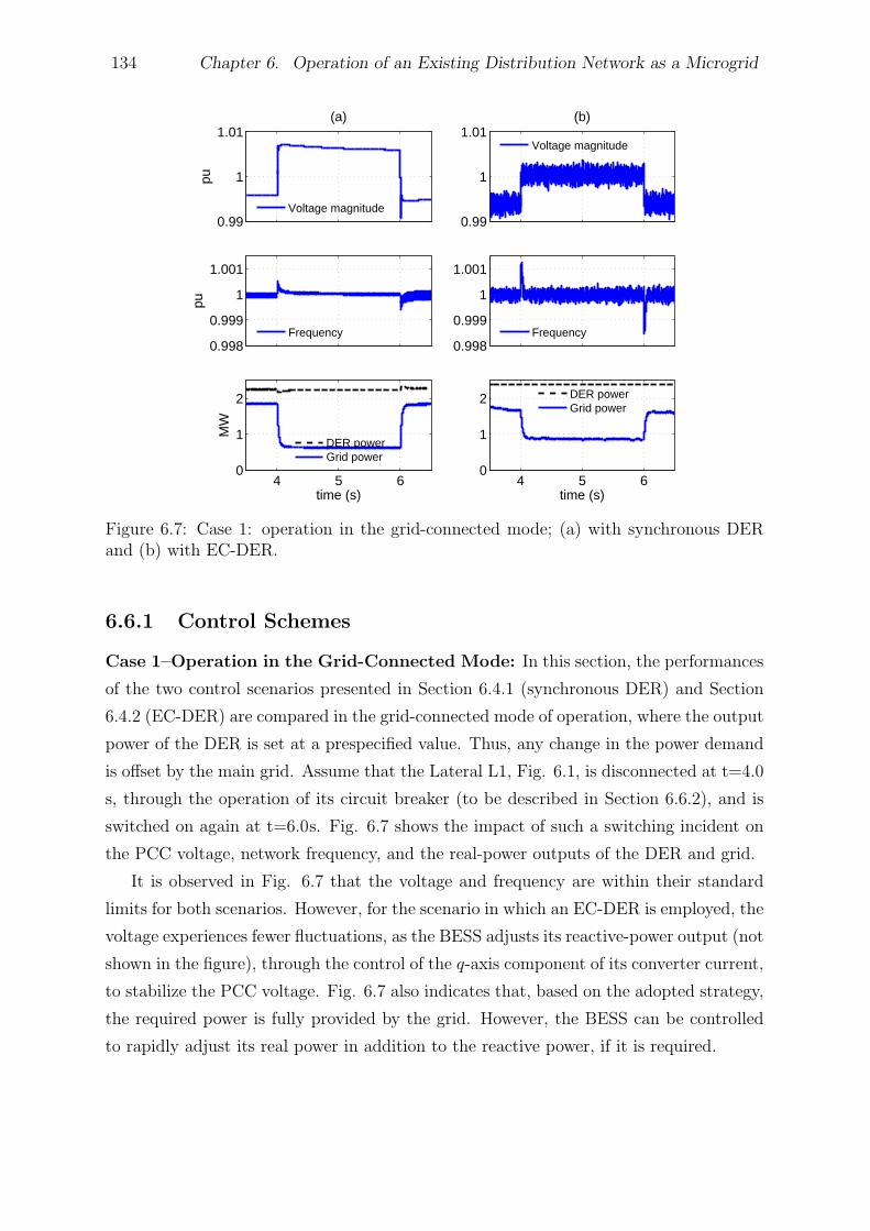
134 Chapter 6. Operation of an Existing Distribution Network as a Microgrid
0.99
1
1.01
pu
(a)
Voltage magnitude0.99
1
1.01(b)
Voltage magnitude
0.998
0.999
1
1.001
pu
Frequency0.998
0.999
1
1.001
Frequency
4 5 60
1
2
time (s)
MW
DER powerGrid power
4 5 60
1
2
time (s)
DER powerGrid power
Figure 6.7: Case 1: operation in the grid-connected mode; (a) with synchronous DERand (b) with EC-DER.
6.6.1 Control Schemes
Case 1–Operation in the Grid-Connected Mode: In this section, the performances
of the two control scenarios presented in Section 6.4.1 (synchronous DER) and Section
6.4.2 (EC-DER) are compared in the grid-connected mode of operation, where the output
power of the DER is set at a prespecified value. Thus, any change in the power demand
is offset by the main grid. Assume that the Lateral L1, Fig. 6.1, is disconnected at t=4.0
s, through the operation of its circuit breaker (to be described in Section 6.6.2), and is
switched on again at t=6.0s. Fig. 6.7 shows the impact of such a switching incident on
the PCC voltage, network frequency, and the real-power outputs of the DER and grid.
It is observed in Fig. 6.7 that the voltage and frequency are within their standard
limits for both scenarios. However, for the scenario in which an EC-DER is employed, the
voltage experiences fewer fluctuations, as the BESS adjusts its reactive-power output (not
shown in the figure), through the control of the q-axis component of its converter current,
to stabilize the PCC voltage. Fig. 6.7 also indicates that, based on the adopted strategy,
the required power is fully provided by the grid. However, the BESS can be controlled
to rapidly adjust its real power in addition to the reactive power, if it is required.
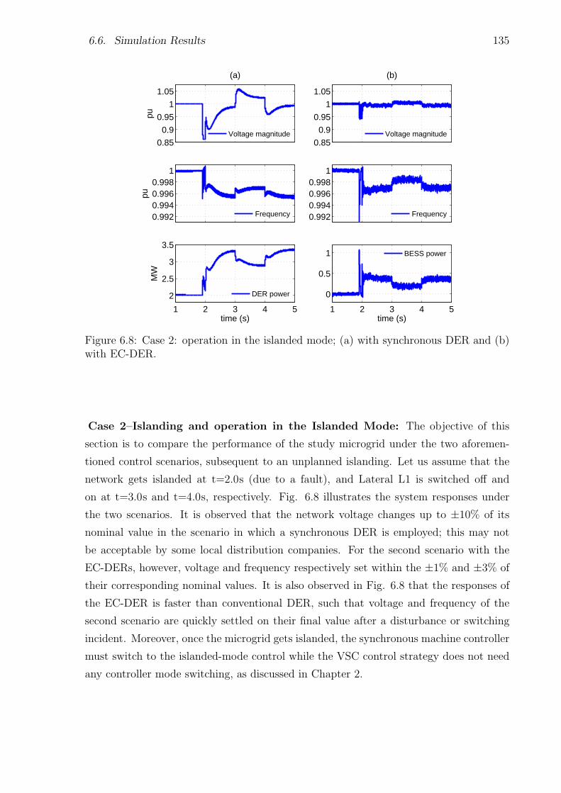
6.6. Simulation Results 135
0.85
0.9
0.95
1
1.05
pu
(a)
Voltage magnitude0.85
0.9
0.95
1
1.05
(b)
Voltage magnitude
0.9920.9940.9960.998
1
pu
Frequency 0.9920.9940.9960.998
1
Frequency
1 2 3 4 5
2
2.5
3
3.5
time (s)
MW
DER power
1 2 3 4 5
0
0.5
1
time (s)
BESS power
Figure 6.8: Case 2: operation in the islanded mode; (a) with synchronous DER and (b)with EC-DER.
Case 2–Islanding and operation in the Islanded Mode: The objective of this
section is to compare the performance of the study microgrid under the two aforemen-
tioned control scenarios, subsequent to an unplanned islanding. Let us assume that the
network gets islanded at t=2.0s (due to a fault), and Lateral L1 is switched off and
on at t=3.0s and t=4.0s, respectively. Fig. 6.8 illustrates the system responses under
the two scenarios. It is observed that the network voltage changes up to ±10% of its
nominal value in the scenario in which a synchronous DER is employed; this may not
be acceptable by some local distribution companies. For the second scenario with the
EC-DERs, however, voltage and frequency respectively set within the ±1% and ±3% of
their corresponding nominal values. It is also observed in Fig. 6.8 that the responses of
the EC-DER is faster than conventional DER, such that voltage and frequency of the
second scenario are quickly settled on their final value after a disturbance or switching
incident. Moreover, once the microgrid gets islanded, the synchronous machine controller
must switch to the islanded-mode control while the VSC control strategy does not need
any controller mode switching, as discussed in Chapter 2.
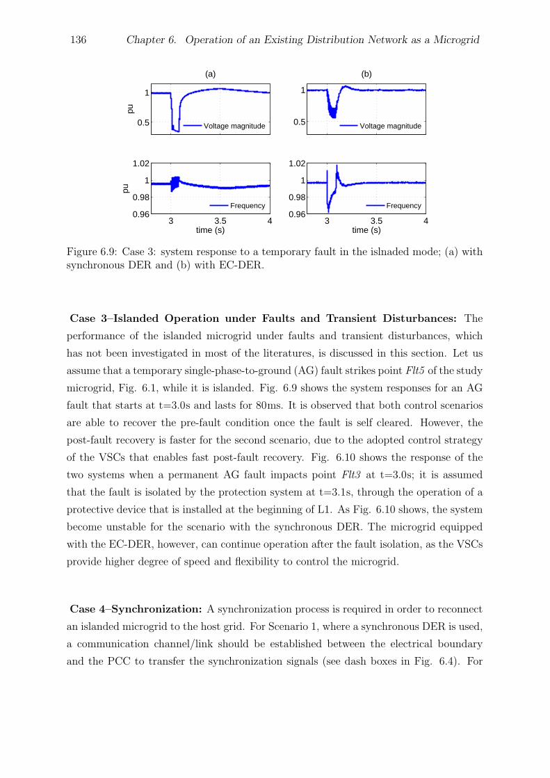
136 Chapter 6. Operation of an Existing Distribution Network as a Microgrid
0.5
1
pu
(a)
Voltage magnitude 0.5
1
(b)
Voltage magnitude
3 3.5 40.96
0.98
1
1.02
time (s)
pu
Frequency
3 3.5 40.96
0.98
1
1.02
time (s)
Frequency
Figure 6.9: Case 3: system response to a temporary fault in the islnaded mode; (a) withsynchronous DER and (b) with EC-DER.
Case 3–Islanded Operation under Faults and Transient Disturbances: The
performance of the islanded microgrid under faults and transient disturbances, which
has not been investigated in most of the literatures, is discussed in this section. Let us
assume that a temporary single-phase-to-ground (AG) fault strikes point Flt5 of the study
microgrid, Fig. 6.1, while it is islanded. Fig. 6.9 shows the system responses for an AG
fault that starts at t=3.0s and lasts for 80ms. It is observed that both control scenarios
are able to recover the pre-fault condition once the fault is self cleared. However, the
post-fault recovery is faster for the second scenario, due to the adopted control strategy
of the VSCs that enables fast post-fault recovery. Fig. 6.10 shows the response of the
two systems when a permanent AG fault impacts point Flt3 at t=3.0s; it is assumed
that the fault is isolated by the protection system at t=3.1s, through the operation of a
protective device that is installed at the beginning of L1. As Fig. 6.10 shows, the system
become unstable for the scenario with the synchronous DER. The microgrid equipped
with the EC-DER, however, can continue operation after the fault isolation, as the VSCs
provide higher degree of speed and flexibility to control the microgrid.
Case 4–Synchronization: A synchronization process is required in order to reconnect
an islanded microgrid to the host grid. For Scenario 1, where a synchronous DER is used,
a communication channel/link should be established between the electrical boundary
and the PCC to transfer the synchronization signals (see dash boxes in Fig. 6.4). For
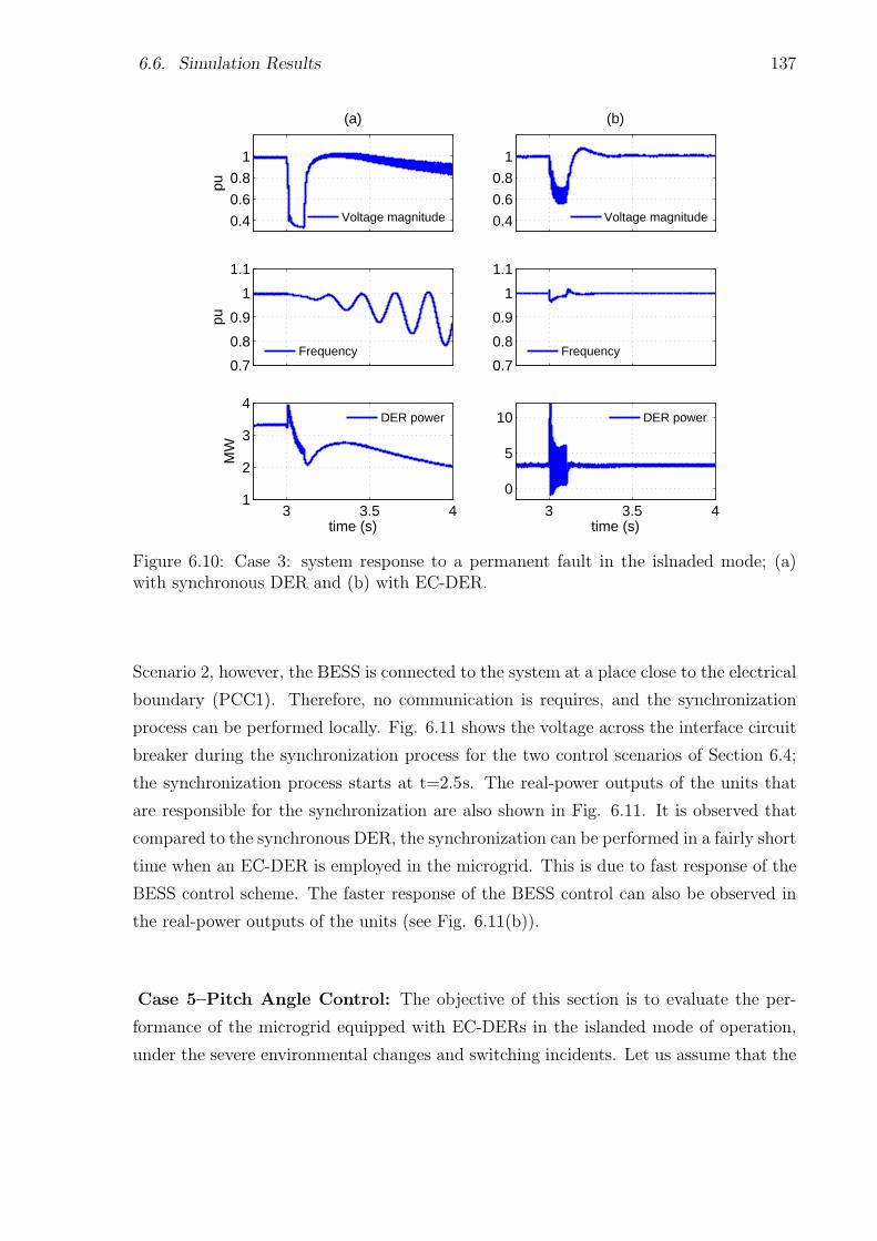
6.6. Simulation Results 137
0.4
0.6
0.8
1
pu
(a)
Voltage magnitude 0.4
0.6
0.8
1
(b)
Voltage magnitude
0.7
0.8
0.9
1
1.1
pu
Frequency0.7
0.8
0.9
1
1.1
Frequency
3 3.5 41
2
3
4
time (s)
MW
DER power
3 3.5 4
0
5
10
time (s)
DER power
Figure 6.10: Case 3: system response to a permanent fault in the islnaded mode; (a)with synchronous DER and (b) with EC-DER.
Scenario 2, however, the BESS is connected to the system at a place close to the electrical
boundary (PCC1). Therefore, no communication is requires, and the synchronization
process can be performed locally. Fig. 6.11 shows the voltage across the interface circuit
breaker during the synchronization process for the two control scenarios of Section 6.4;
the synchronization process starts at t=2.5s. The real-power outputs of the units that
are responsible for the synchronization are also shown in Fig. 6.11. It is observed that
compared to the synchronous DER, the synchronization can be performed in a fairly short
time when an EC-DER is employed in the microgrid. This is due to fast response of the
BESS control scheme. The faster response of the BESS control can also be observed in
the real-power outputs of the units (see Fig. 6.11(b)).
Case 5–Pitch Angle Control: The objective of this section is to evaluate the per-
formance of the microgrid equipped with EC-DERs in the islanded mode of operation,
under the severe environmental changes and switching incidents. Let us assume that the
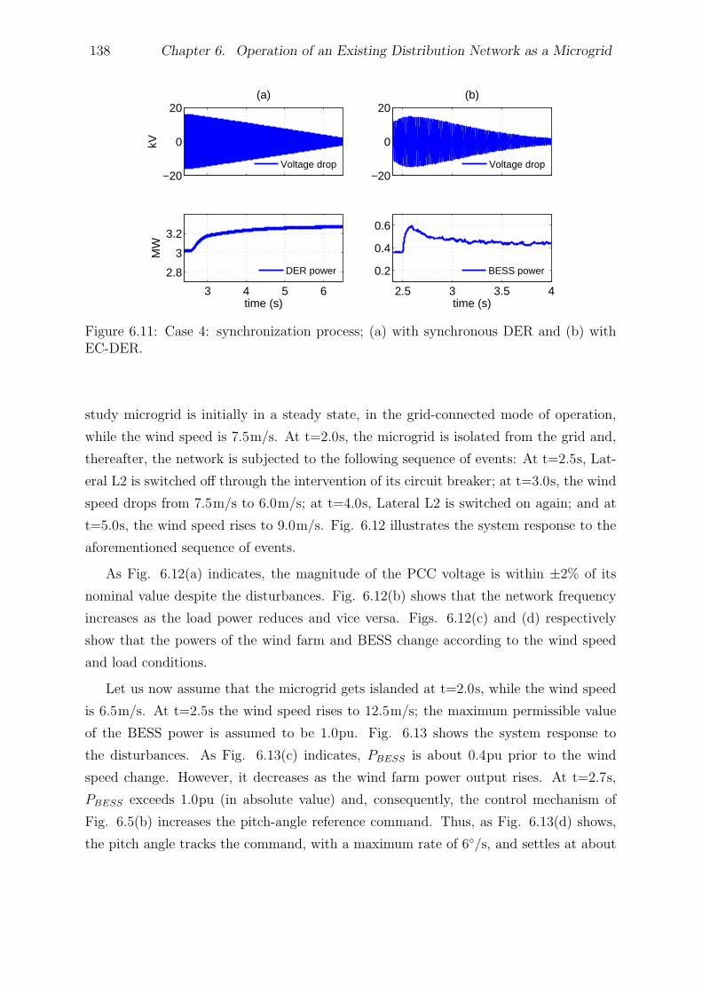
138 Chapter 6. Operation of an Existing Distribution Network as a Microgrid
−20
0
20
kV
(a)
Voltage drop−20
0
20(b)
Voltage drop
3 4 5 6
2.8
3
3.2
time (s)
MW
DER power
2.5 3 3.5 4
0.2
0.4
0.6
time (s)
BESS power
Figure 6.11: Case 4: synchronization process; (a) with synchronous DER and (b) withEC-DER.
study microgrid is initially in a steady state, in the grid-connected mode of operation,
while the wind speed is 7.5m/s. At t=2.0s, the microgrid is isolated from the grid and,
thereafter, the network is subjected to the following sequence of events: At t=2.5s, Lat-
eral L2 is switched off through the intervention of its circuit breaker; at t=3.0s, the wind
speed drops from 7.5m/s to 6.0m/s; at t=4.0s, Lateral L2 is switched on again; and at
t=5.0s, the wind speed rises to 9.0m/s. Fig. 6.12 illustrates the system response to the
aforementioned sequence of events.
As Fig. 6.12(a) indicates, the magnitude of the PCC voltage is within ±2% of its
nominal value despite the disturbances. Fig. 6.12(b) shows that the network frequency
increases as the load power reduces and vice versa. Figs. 6.12(c) and (d) respectively
show that the powers of the wind farm and BESS change according to the wind speed
and load conditions.
Let us now assume that the microgrid gets islanded at t=2.0s, while the wind speed
is 6.5m/s. At t=2.5s the wind speed rises to 12.5m/s; the maximum permissible value
of the BESS power is assumed to be 1.0pu. Fig. 6.13 shows the system response to
the disturbances. As Fig. 6.13(c) indicates, PBESS is about 0.4pu prior to the wind
speed change. However, it decreases as the wind farm power output rises. At t=2.7s,
PBESS exceeds 1.0pu (in absolute value) and, consequently, the control mechanism of
Fig. 6.5(b) increases the pitch-angle reference command. Thus, as Fig. 6.13(d) shows,
the pitch angle tracks the command, with a maximum rate of 6/s, and settles at about
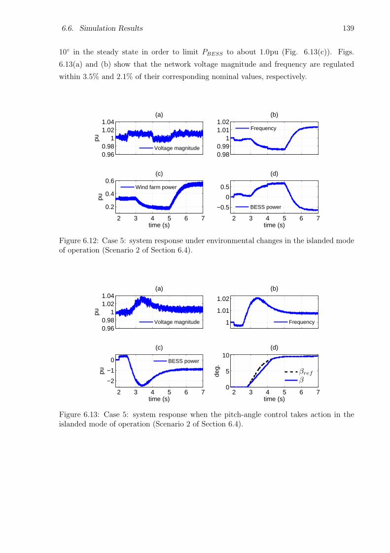
6.6. Simulation Results 139
10 in the steady state in order to limit PBESS to about 1.0pu (Fig. 6.13(c)). Figs.
6.13(a) and (b) show that the network voltage magnitude and frequency are regulated
within 3.5% and 2.1% of their corresponding nominal values, respectively.
0.960.98
11.021.04
pu
(a)
Voltage magnitude0.980.99
11.011.02
(b)
Frequency
2 3 4 5 6 7
0.2
0.4
0.6
time (s)
pu
(c)
Wind farm power
2 3 4 5 6 7
−0.5
0
0.5
time (s)
(d)
BESS power
Figure 6.12: Case 5: system response under environmental changes in the islanded modeof operation (Scenario 2 of Section 6.4).
0.960.98
11.021.04
pu
(a)
Voltage magnitude 1
1.01
1.02
(b)
Frequency
2 3 4 5 6 7
−2
−1
0
time (s)
pu
(c)
BESS power
2 3 4 5 6 70
5
10
time (s)
deg.
(d)
βref
β
Figure 6.13: Case 5: system response when the pitch-angle control takes action in theislanded mode of operation (Scenario 2 of Section 6.4).
140 Chapter 6. Operation of an Existing Distribution Network as a Microgrid
6.6.2 Protection Schemes
To demonstrate the effectiveness of the proposed protection schemes, several fault cases
have been simulated in both the islanded and grid-connected modes of operation. How-
ever, due to space limitations, the results of only a limited number of cases are presented;
the results of other cases are very similar and, thus, not reported in this thesis.
Case 1–Grid-Connected Mode of Operation: As mentioned in Section 6.5.1, the
first step of the protection algorithm is to retrieve the recloser-fuse coordination in the
grid-connected mode of operation, if it is lost. Therefore, the coordination algorithm of
Fig. 3.1 is employed to coordinate the recloser with the lowest-rating fuse of the feeder in
the presence of the DER(s); if the lowest-rating fuse is replaced by a relay, e.g., an MPR,
the recloser should be coordinated with the corresponding MPR. Fig. 6.14 shows the
characteristic curves of the recloser and the lowest-rating fuse (100-A fuse) of the study
microgrid for the case that the synchronous DER is connected to the system. As can
be observed in Fig. 6.14, the proposed coordination algorithm is separately exercised for
the phase and ground units. It is remembered that recloser-fuse miscoordination is more
likely to happen in the presence of the conventional DERs, as EC-DERs have limited
fault current ratings. To simulate the worst-case transient condition for the recloser-fuse
coordination, the impact of the FCL has not been considered in the calculation of the
minimum and maximum fault currents, as discussed in Section 6.5.1–2. This also ensures
that the recloser-fuse coordination can be achieved for both scenarios of Section 6.5.1; the
calculation of the minimum and maximum fault currents (Ifmin and Ifmax) is explained
in Chapter 3. Fig. 6.14 shows that the recloser-fuse coordination is achieved for the
grid-connected mode of operation such that the recloser always operates first for each
fault incident.
Once the recloser operates in its fast mode, either of the two protection scenarios
of Section 6.5.1 (i.e., the use of a transfer trip mechanism through a communication
channel or the use of an FCL) can be adopted. The objective of the two options is to
eliminate/limit the contribution of the DER(s) for a permanent fault so that the fuse-fuse
coordination is preserved (see Chapter 3). However, the first option requires communica-
tions which may not be available or it may be costly; thus, the employment of the FCL
is studied in this chapter. The FCL is assumed to be of the superconducting type [128],
and its impedance value is determined in such a manner that the fuse-fuse coordination
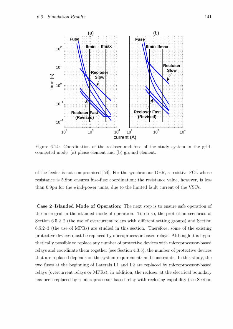
6.6. Simulation Results 141
102
103
104
10−2
10−1
100
101
102
current (A)
time
(s)
(a)
102
103
104
(b)
IfmaxIfmin
Fuse
RecloserSlow
Recloser Fast(Revised)
RecloserSlow
Ifmax
Fuse
Recloser Fast(Revised)
Ifmin
Figure 6.14: Coordination of the recloser and fuse of the study system in the grid-connected mode; (a) phase element and (b) ground element.
of the feeder is not compromised [54]. For the synchronous DER, a resistive FCL whose
resistance is 5.8pu ensures fuse-fuse coordination; the resistance value, however, is less
than 0.9pu for the wind-power units, due to the limited fault current of the VSCs.
Case 2–Islanded Mode of Operation: The next step is to ensure safe operation of
the microgrid in the islanded mode of operation. To do so, the protection scenarios of
Section 6.5.2–2 (the use of overcurrent relays with different setting groups) and Section
6.5.2–3 (the use of MPRs) are studied in this section. Therefore, some of the existing
protective devices must be replaced by microprocessor-based relays. Although it is hypo-
thetically possible to replace any number of protective devices with microprocessor-based
relays and coordinate them together (see Section 4.3.5), the number of protective devices
that are replaced depends on the system requirements and constraints. In this study, the
two fuses at the beginning of Laterals L1 and L2 are replaced by microprocessor-based
relays (overcurrent relays or MPRs); in addition, the recloser at the electrical boundary
has been replaced by a microprocessor-based relay with reclosing capability (see Section
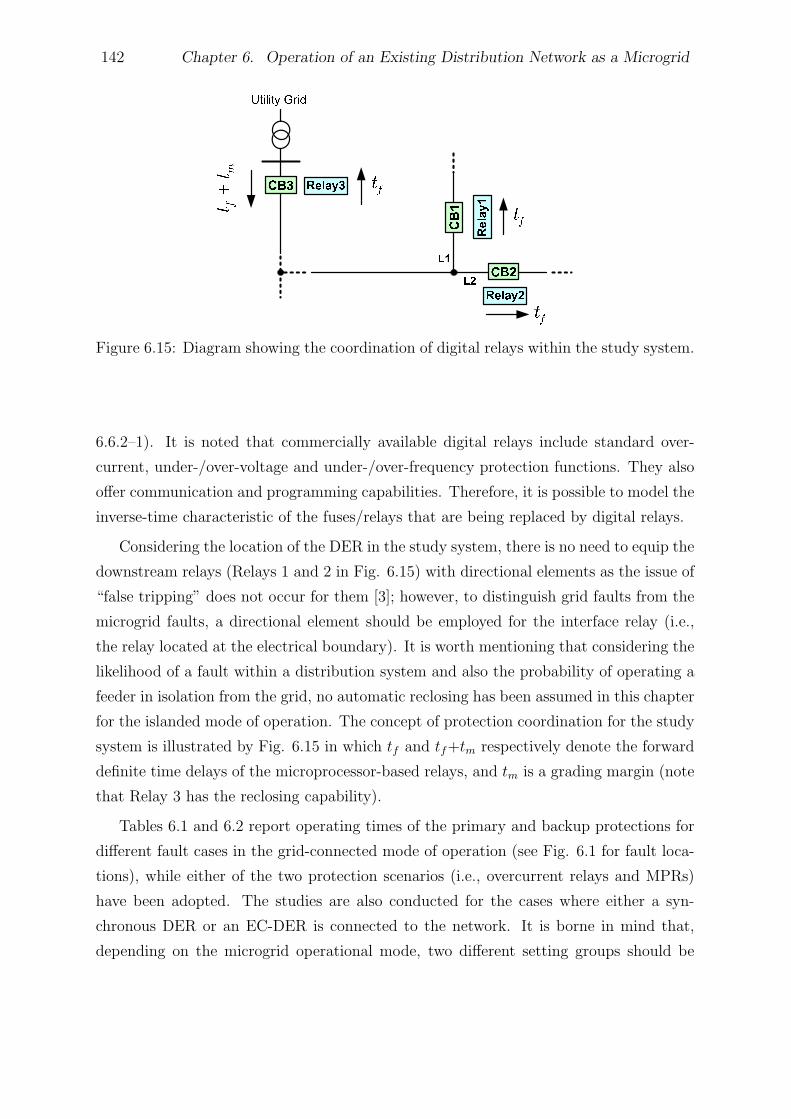
142 Chapter 6. Operation of an Existing Distribution Network as a Microgrid
Figure 6.15: Diagram showing the coordination of digital relays within the study system.
6.6.2–1). It is noted that commercially available digital relays include standard over-
current, under-/over-voltage and under-/over-frequency protection functions. They also
offer communication and programming capabilities. Therefore, it is possible to model the
inverse-time characteristic of the fuses/relays that are being replaced by digital relays.
Considering the location of the DER in the study system, there is no need to equip the
downstream relays (Relays 1 and 2 in Fig. 6.15) with directional elements as the issue of
“false tripping” does not occur for them [3]; however, to distinguish grid faults from the
microgrid faults, a directional element should be employed for the interface relay (i.e.,
the relay located at the electrical boundary). It is worth mentioning that considering the
likelihood of a fault within a distribution system and also the probability of operating a
feeder in isolation from the grid, no automatic reclosing has been assumed in this chapter
for the islanded mode of operation. The concept of protection coordination for the study
system is illustrated by Fig. 6.15 in which tf and tf+tm respectively denote the forward
definite time delays of the microprocessor-based relays, and tm is a grading margin (note
that Relay 3 has the reclosing capability).
Tables 6.1 and 6.2 report operating times of the primary and backup protections for
different fault cases in the grid-connected mode of operation (see Fig. 6.1 for fault loca-
tions), while either of the two protection scenarios (i.e., overcurrent relays and MPRs)
have been adopted. The studies are also conducted for the cases where either a syn-
chronous DER or an EC-DER is connected to the network. It is borne in mind that,
depending on the microgrid operational mode, two different setting groups should be
6.7. Summary and Conclusion 143
employed for overcurrent relays, as discussed in Section 6.5.2. Switching from one set-
ting group to the other one can be performed by an anti-islanding mechanism embedded
in the digital relays and, thus, no communication link is required. Therefore, once the
microgrid gets islanded, the anti-islanding signal is activated and the islanded setting
group is enabled. It is also noted that the use of MPRS has the advantage of protecting
the network against high-impedance faults.
Several cases have also been simulated for the islanded mode of operation but, due
to space limitations, the results of only a selected number of them have been reported
in Tables 6.3 and 6.4. Similar to the grid-connected mode of operation, it is observed
that the coordination between the protective devices is obtained for any fault within the
islanded micrgrid, irrespective of the DER type.
6.7 Summary and Conclusion
A realistic distribution network embedding a distributed energy resource was studied in
this chapter to identify the conditions and scenarios under which the network can operate
as a microgrid. Possible control scenarios that could enable autonomous operation of an
existing distribution network were investigated in the chapter, and their advantages and
disadvantages were discussed. A suitable control strategy was employed for the EC-DER
such that the microgrid can ride through transient incidents, get synchronized with the
host utility grid, and slide between two modes of operation. Practical protection strate-
gies were also proposed to protect the study microgrid against different fault scenarios
in both operational modes. The best control and protection options are selected based
on the requirements and constraints of the local distribution companies. Several study
cases were conducted based on digital time-domain simulation of the study system, to
demonstrate the effective performance of the proposed control/protection strategies. The
thesis is summarized and concluded in the next chapter.

144 Chapter 6. Operation of an Existing Distribution Network as a Microgrid
Table 6.1: Operating Times of the Main and Backup Protection for Selected Fault Sce-narios in the Grid-Connected Mode of Operation (with OCRs)
Fault Fault Overcurrent Relays (OCRs)
Type Loc. Main Protection Backup Protection
Prot. Opr. Prot. Opr.
Device Time(s) Device Time(s)
Rotating-Machine-Based DER
AG Flt1 R 0.060 cb1 0.171
AG Flt4 R 0.154 F4 0.417
AG Flt5 R 0.096 OCR2 0.486
BCG Flt2 R 0.092 F2 0.689
BC Flt3 R 0.137 OCR1 0.509
ABC Flt6 R 0.105 F6 0.311
Electronically Coupled DER
AG Flt1 R 0.053 cb1 0.174
AG Flt4 R 0.141 F4 0.417
AG Flt5 R 0.087 OCR2 0.486
BCG Flt2 R 0.082 F2 0.690
BC Flt3 R 0.104 OCR1 0.508
ABC Flt6 R 0.090 F6 0.311
Table 6.2: Operating Times of the Main and Backup Protection for Selected Fault Sce-narios in the Grid-Connected Mode of Operation (with MPRs)
Fault Fault Microgrid Protection Relays (MPRs)
Type Loc. Main Protection Backup Protection
Prot. Opr. Prot. Opr.
Device Time(s) Device Time(s)
Rotating-Machine-Based DER
AG Flt1 R 0.060 cb1 0.171
AG Flt4 R 0.154 F4 0.417
AG Flt5 R 0.096 MPR2 0.461
BCG Flt2 R 0.092 F2 0.689
BC Flt3 R 0.137 MPR1 0.460
ABC Flt6 R 0.105 F6 0.311
Electronically Coupled DER
AG Flt1 R 0.053 cb1 0.174
AG Flt4 R 0.141 F4 0.417
AG Flt5 R 0.087 MPR2 0.460
BCG Flt2 R 0.082 F2 0.690
BC Flt3 R 0.114 MPR1 0.460
ABC Flt6 R 0.090 F6 0.311
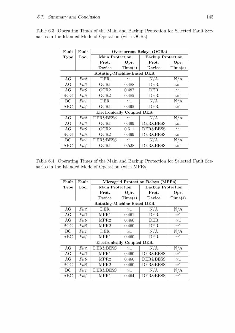
6.7. Summary and Conclusion 145
Table 6.3: Operating Times of the Main and Backup Protection for Selected Fault Sce-narios in the Islanded Mode of Operation (with OCRs)
Fault Fault Overcurrent Relays (OCRs)
Type Loc. Main Protection Backup Protection
Prot. Opr. Prot. Opr.
Device Time(s) Device Time(s)
Rotating-Machine-Based DER
AG Flt2 DER ≃1 N/A N/A
AG Flt3 OCR1 0.488 DER ≃1
AG Flt6 OCR2 0.487 DER ≃1
BCG Flt5 OCR2 0.485 DER ≃1
BC Flt1 DER ≃1 N/A N/A
ABC Flt4 OCR1 0.495 DER ≃1
Electronically Coupled DER
AG Flt2 DER&BESS ≃1 N/A N/A
AG Flt3 OCR1 0.499 DER&BESS ≃1
AG Flt6 OCR2 0.511 DER&BESS ≃1
BCG Flt5 OCR2 0.499 DER&BESS ≃1
BC Flt1 DER&BESS ≃1 N/A N/A
ABC Flt4 OCR1 0.528 DER&BESS ≃1
Table 6.4: Operating Times of the Main and Backup Protection for Selected Fault Sce-narios in the Islanded Mode of Operation (with MPRs)
Fault Fault Microgrid Protection Relays (MPRs)
Type Loc. Main Protection Backup Protection
Prot. Opr. Prot. Opr.
Device Time(s) Device Time(s)
Rotating-Machine-Based DER
AG Flt2 DER ≃1 N/A N/A
AG Flt3 MPR1 0.461 DER ≃1
AG Flt6 MPR2 0.460 DER ≃1
BCG Flt5 MPR2 0.460 DER ≃1
BC Flt1 DER ≃1 N/A N/A
ABC Flt4 MPR1 0.460 DER ≃1
Electronically Coupled DER
AG Flt2 DER&BESS ≃1 N/A N/A
AG Flt3 MPR1 0.460 DER&BESS ≃1
AG Flt6 MPR2 0.460 DER&BESS ≃1
BCG Flt5 MPR2 0.460 DER&BESS ≃1
BC Flt1 DER&BESS ≃1 N/A N/A
ABC Flt4 MPR1 0.464 DER&BESS ≃1
Chapter 7
Summary, Conclusions, and
FutureWork
7.1 Summary
The economical and environmental merits of microgrids have motivated extensive re-
searches and development efforts toward resolving the technical challenges of this new
and fast-growing technology. The main objective of this research is to address some
concerns related to the control and protection of microgrids. The issues studied in the
thesis can generally be classified into two parts: (i) control of EC-DERs under network
faults and transient disturbances, and (ii) protection of the microgrid against different
fault scenarios in both modes of operation.
In Chapter 1 of this thesis, the research objectives and the contributions of the thesis
are presented. Chapter 1 also includes an introduction to the microgrid systems and their
advantages and challenges. Chapter 2 mainly focuses on the modeling and control of EC-
DERs; in this chapter, a basic control strategy is first adopted and modified for multi-unit
microgrids. Then, the chapter outlines the shortcomings of the basic control strategy,
modifies it for operation under fault incidents and severe network voltage imbalances, and
proposes a phase-angle restoration loop to improve the post-fault recovery of the EC-DER
and the host microgrid. A synchronization algorithm is also proposed in Chapter 2 of
the thesis.
Coordination of protective devices in radial distribution networks embedding DERs
is discussed in Chapter 3. A simple and effective protection strategy is proposed in the
chapter that provides coordination amongst protective devices of a typical distribution
146
7.2. Conclusion 147
system with DERs. Moreover, this chapter presents the steps taken to characterize
the impact of future addition of DERs on the protection coordination, for host and
neighboring feeders, in a typical distribution network.
Chapter 4 of the thesis investigates the issues associated with protection of microgrids
and proposes a protection strategy for low-voltage/residential microgrids. The proposed
protection strategy, which does not require communications or adaptive protective de-
vices, can be implemented through programmable microprocessor-based relays; it also
addresses protection issues of a microgrid in both modes of operation. In Chapter 5, a
communication-assisted protection strategy is proposed for large medium-voltage micro-
grid, where a fast fault clearance is desired. A backup protection strategy is also offered
in this chapter to manage communication network failures. The structure of new relays
enabling the proposed protection strategies are also presented in Chapters 4 and 5.
Finally, Chapter 6 of the thesis studies an existing distribution network and presents
different control scenarios that enable the network to operate as a microgrid. Practical
protection strategies that are effective for the established microgrid (considering the
system requirements/constraints) are also discussed in Chapter 6. The main goal of this
chapter is to provide the reader with practical scenarios enabling a realistic distribution
network to operate as a temporary island.
7.2 Conclusion
The conclusions of this thesis are as follows:
• Fast and reliable regulation of the magnitude and frequency of DER terminal volt-
ages is an essential task in the control of microgrids. It was discussed that the
terminal voltage of an EC-DER can seriously be affected by system imbalances,
network faults, and transient incidents; the effect appears as an undesirable har-
monic distortion in the DER terminal voltage. The thesis showed that, under
unbalanced load conditions, an enhanced control strategy based on multiple con-
trol loops (i.e., an inner current loop and an outer voltage loop) can effectively
regulate the terminal voltage magnitude and frequency; it can also mitigate the
impacts of load dynamics, inherent intercoupling, and sever network imbalances
on the system performance and preserve the quality of power. The thesis further
explained that the rapid post-fault recovery of the microgrid can be achieved by
augmenting the q-axis component of the terminal voltage through a supplementary
148 Chapter 7. Summary, Conclusions, and FutureWork
control loop.
• The thesis discussed that the integration of DERs into distribution networks can
compromise the coordination amongst the protective devices of the network. The
impacts of DERs on the protection coordination and the corresponding issues were
addressed in the thesis. It was demonstrated that an effective coordination algo-
rithm can retrieve the protection coordination in typical/radial distribution net-
works embedding DERs, if programmable digital reclosers are employed at the
beginning of the network feeders. The proposed coordination scheme can address
the issues associated with the grid-connected operation of a microgrid.
• It is essential to protect a microgrid in the islanded mode as well as the grid-
connected mode of operation, against all types of faults. The major issue in
the islanded mode of operation arises due to the limited fault current capabil-
ity of EC-DERs. The thesis demonstrated that a protection strategy based on
commercially available microprocessor-based relays can be devised to protect low-
voltage/resdiential microgrids in both operational modes. The salient feature of the
developed protection strategy is that it does not require communications or adap-
tive protective devices, and is independent of the fault current magnitude and the
mode of operation. The structure of a new relay enabling the proposed protection
strategy is also presented in the thesis.
• The proposed protection scheme for low-voltage microgrids can also be applied
for a large medium-voltage microgrid; however, it may take a relatively long time
to isolate a fault within medium-voltage microgrids, as it applies a definite-time
grading strategy for protection coordination. Therefore, the thesis proposed a
communication-assisted protection strategy for medium-voltage microgrids where
faster fault isolation is required. The proposed protection scheme also offers a
backup protection in case the communication network fails to operate. The pro-
posed strategy aims to detect and isolate the faults within radial distribution net-
works that are operated as a microgrid, in a selective (coordinated) manner. It was
demonstrated that the effectiveness of the proposed strategy, which benefits from
directional elements and microprocessor-based relays, is to a large extent indepen-
dent of the fault current levels, the mode of operation, as well as the type and
size of DERs, subject to the modified relay settings for the grid-connected mode of
operation.
7.3. Future Works 149
7.3 Future Works
The following topics are suggested for a future work:
• An investigation into the type, transient regimes, and impedance calculation of fault
current limiters (FCLs): One of the methods proposed to retrieve the coordination
of overcurrent devices in distribution networks with DERs is the use FCLs (see
Chapter 6). However, most of the researches have not formulated or characterized
the problem of impedance calculation for FCLs, nor have they studied the transient
regimes associated with FCLs; this could be a potential area for future research.
• Real-time simulation of the proposed protection/control methods with the use of
Real-Time Digital Simulator (RTDS): The real-time simulation results are more
reliable than those obtained by offline simulation; therefore, real-time simulation is
preferably performed after offline simulation but before experimental investigation,
as a sequential procedure for testing the system performance in such complex plants
as electric power systems. The real-time simulation is, thus, the next step toward
the realization of the proposed strategies.
• Designing a reliable protection strategy for microgrids with loop structure: As the
penetration of DERs increases, distribution networks will experience looped oper-
ation to achieve higher reliability. This, in turn, results in looped configurations
within the future microgrids. Therefore, it is required to devise appropriate protec-
tion schemes that enable safe operation of the looped microgrids in both operational
modes.
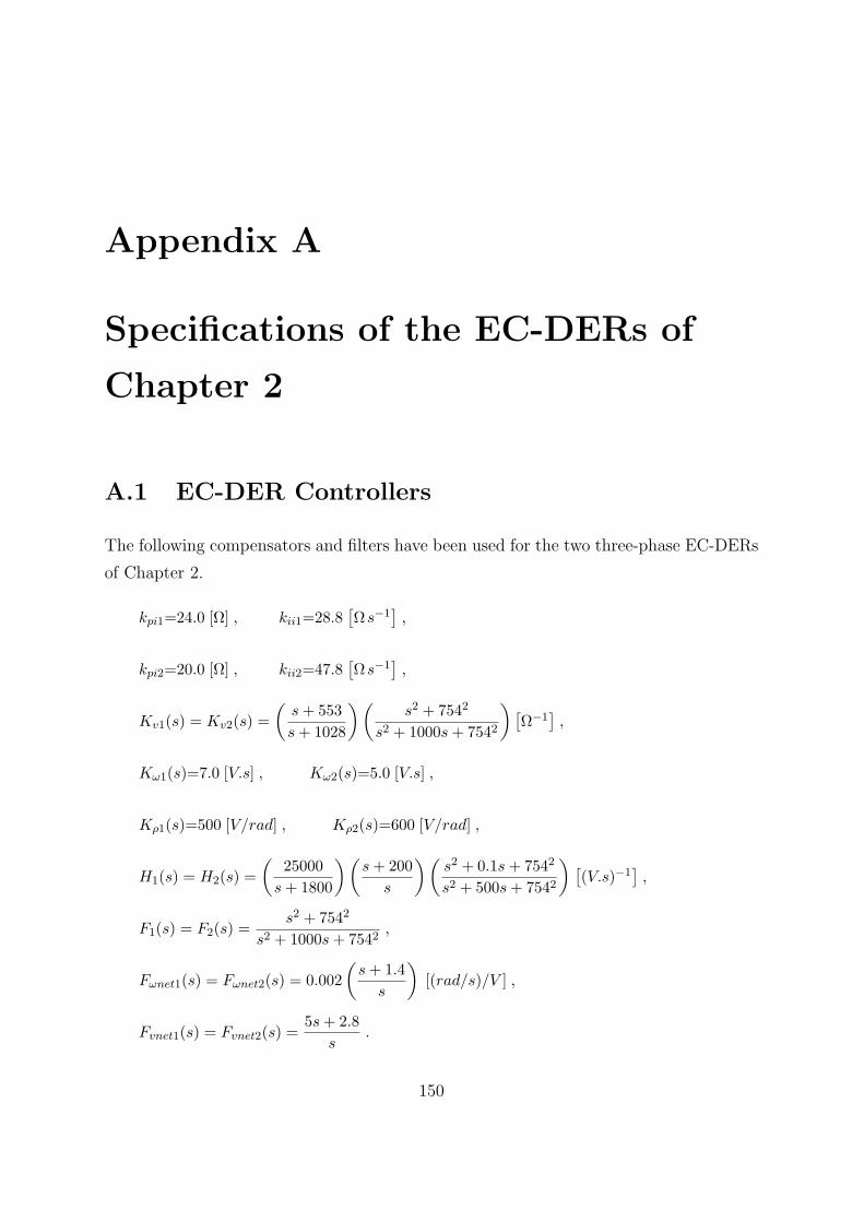
Appendix A
Specifications of the EC-DERs of
Chapter 2
A.1 EC-DER Controllers
The following compensators and filters have been used for the two three-phase EC-DERs
of Chapter 2.
kpi1=24.0 [Ω] , kii1=28.8[Ωs−1
],
kpi2=20.0 [Ω] , kii2=47.8[Ωs−1
],
Kv1(s) = Kv2(s) =
(s+ 553
s+ 1028
)(s2 + 7542
s2 + 1000s+ 7542
)[Ω−1
],
Kω1(s)=7.0 [V.s] , Kω2(s)=5.0 [V.s] ,
Kρ1(s)=500 [V/rad] , Kρ2(s)=600 [V/rad] ,
H1(s) = H2(s) =
(25000
s+ 1800
)(s+ 200
s
)(s2 + 0.1s+ 7542
s2 + 500s+ 7542
) [(V.s)−1
],
F1(s) = F2(s) =s2 + 7542
s2 + 1000s+ 7542,
Fωnet1(s) = Fωnet2(s) = 0.002
(s+ 1.4
s
)[(rad/s)/V ] ,
Fvnet1(s) = Fvnet2(s) =5s+ 2.8
s.
150
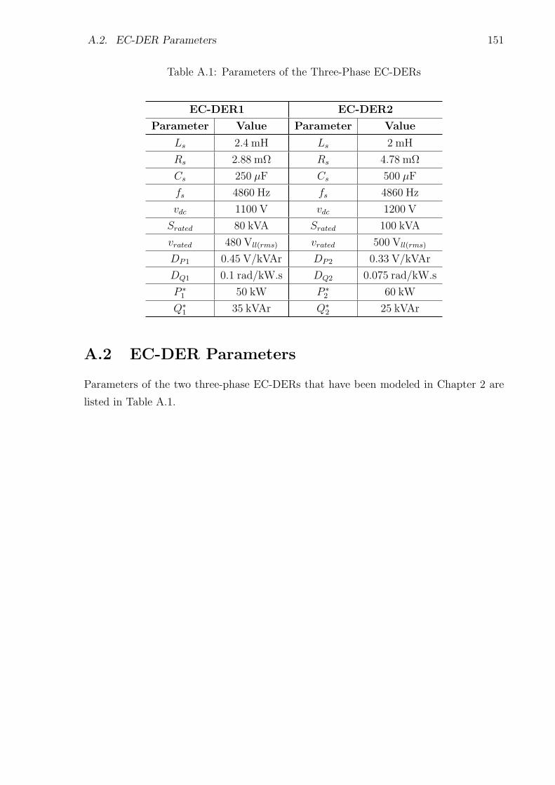
A.2. EC-DER Parameters 151
Table A.1: Parameters of the Three-Phase EC-DERs
EC-DER1 EC-DER2
Parameter Value Parameter Value
Ls 2.4 mH Ls 2 mH
Rs 2.88 mΩ Rs 4.78 mΩ
Cs 250 µF Cs 500 µF
fs 4860 Hz fs 4860 Hz
vdc 1100 V vdc 1200 V
Srated 80 kVA Srated 100 kVA
vrated 480 Vll(rms) vrated 500 Vll(rms)
DP1 0.45 V/kVAr DP2 0.33 V/kVAr
DQ1 0.1 rad/kW.s DQ2 0.075 rad/kW.s
P ∗1 50 kW P ∗
2 60 kW
Q∗1 35 kVAr Q∗
2 25 kVAr
A.2 EC-DER Parameters
Parameters of the two three-phase EC-DERs that have been modeled in Chapter 2 are
listed in Table A.1.
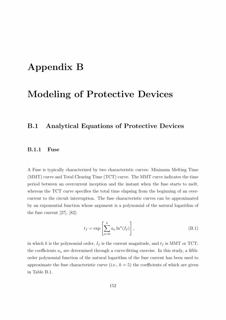
Appendix B
Modeling of Protective Devices
B.1 Analytical Equations of Protective Devices
B.1.1 Fuse
A Fuse is typically characterized by two characteristic curves: Minimum Melting Time
(MMT) curve and Total Clearing Time (TCT) curve. The MMT curve indicates the time
period between an overcurrent inception and the instant when the fuse starts to melt,
whereas the TCT curve specifies the total time elapsing from the beginning of an over-
current to the circuit interruption. The fuse characteristic curves can be approximated
by an exponential function whose argument is a polynomial of the natural logarithm of
the fuse current [27], [82]:
tf = exp
[k∑
n=0
an lnn(If )
], (B.1)
in which k is the polynomial order, If is the current magnitude, and tf is MMT or TCT;
the coefficients an are determined through a curve-fitting exercise. In this study, a fifth-
order polynomial function of the natural logarithm of the fuse current has been used to
approximate the fuse characteristic curve (i.e., k = 5) the coefficients of which are given
in Table B.1.
152
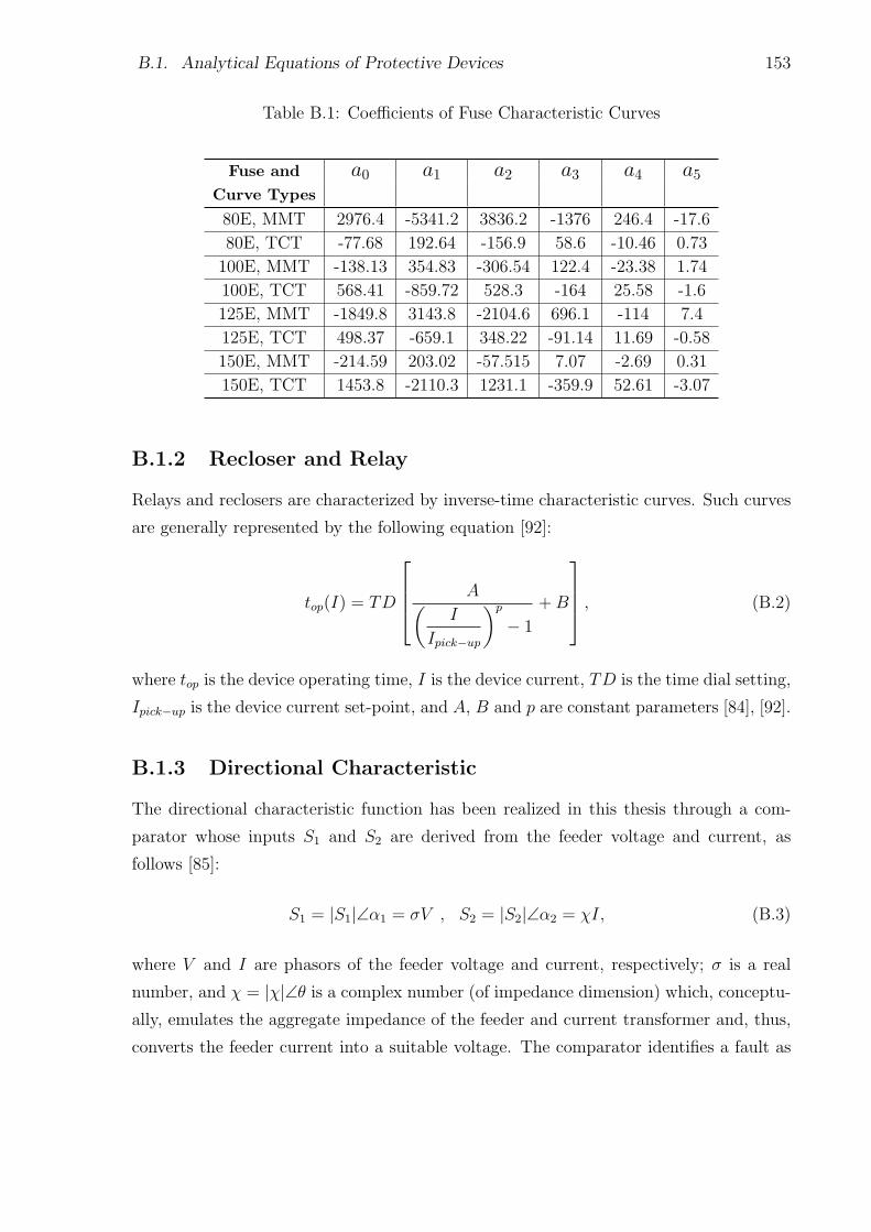
B.1. Analytical Equations of Protective Devices 153
Table B.1: Coefficients of Fuse Characteristic Curves
Fuse and a0 a1 a2 a3 a4 a5Curve Types
80E, MMT 2976.4 -5341.2 3836.2 -1376 246.4 -17.6
80E, TCT -77.68 192.64 -156.9 58.6 -10.46 0.73
100E, MMT -138.13 354.83 -306.54 122.4 -23.38 1.74
100E, TCT 568.41 -859.72 528.3 -164 25.58 -1.6
125E, MMT -1849.8 3143.8 -2104.6 696.1 -114 7.4
125E, TCT 498.37 -659.1 348.22 -91.14 11.69 -0.58
150E, MMT -214.59 203.02 -57.515 7.07 -2.69 0.31
150E, TCT 1453.8 -2110.3 1231.1 -359.9 52.61 -3.07
B.1.2 Recloser and Relay
Relays and reclosers are characterized by inverse-time characteristic curves. Such curves
are generally represented by the following equation [92]:
top(I) = TD
A(I
Ipick−up
)p
− 1
+B
, (B.2)
where top is the device operating time, I is the device current, TD is the time dial setting,
Ipick−up is the device current set-point, and A, B and p are constant parameters [84], [92].
B.1.3 Directional Characteristic
The directional characteristic function has been realized in this thesis through a com-
parator whose inputs S1 and S2 are derived from the feeder voltage and current, as
follows [85]:
S1 = |S1|∠α1 = σV , S2 = |S2|∠α2 = χI, (B.3)
where V and I are phasors of the feeder voltage and current, respectively; σ is a real
number, and χ = |χ|∠θ is a complex number (of impedance dimension) which, conceptu-
ally, emulates the aggregate impedance of the feeder and current transformer and, thus,
converts the feeder current into a suitable voltage. The comparator identifies a fault as
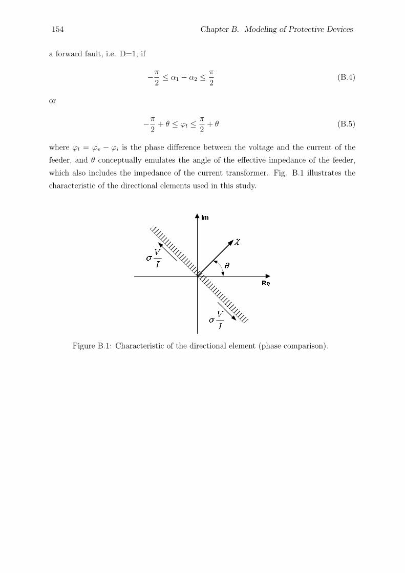
154 Chapter B. Modeling of Protective Devices
a forward fault, i.e. D=1, if
−π
2≤ α1 − α2 ≤
π
2(B.4)
or
−π
2+ θ ≤ φl ≤
π
2+ θ (B.5)
where φl = φv − φi is the phase difference between the voltage and the current of the
feeder, and θ conceptually emulates the angle of the effective impedance of the feeder,
which also includes the impedance of the current transformer. Fig. B.1 illustrates the
characteristic of the directional elements used in this study.
Figure B.1: Characteristic of the directional element (phase comparison).
Appendix C
Relay Settings and Device Numbers
for Chapter 4
C.1 Relay Settings
Tables C.1, C.2, C.3, and C.4 report the parameters of the MPRs and the IMPR that are
employed in Chapter 4. The time delays of the MPRs and the IMPR (for the islanded
and grid-connected modes of operation) are respectively shown in Table C.1 and C.2.
Table C.3 reports the settings of the inverse-time overcurrent functions of the microgrid
protection relays. Finally, the settings of the three-phase protection modules of the relays
are indicated in Table C.4.
C.2 Device/Function Numbers
Table C.5 shows the standard device/function numbers employed in this study. Each
number with its corresponding function name is listed in the table. It is noted that
the use of the word “relay” in the function names is intended to be generic, and does
not necessarily imply a separate freestanding single function device. The numbers are
extracted from IEEE Standard for Electrical Power System Device Function Numbers,
Acronyms, and Contact Designations [102].
155
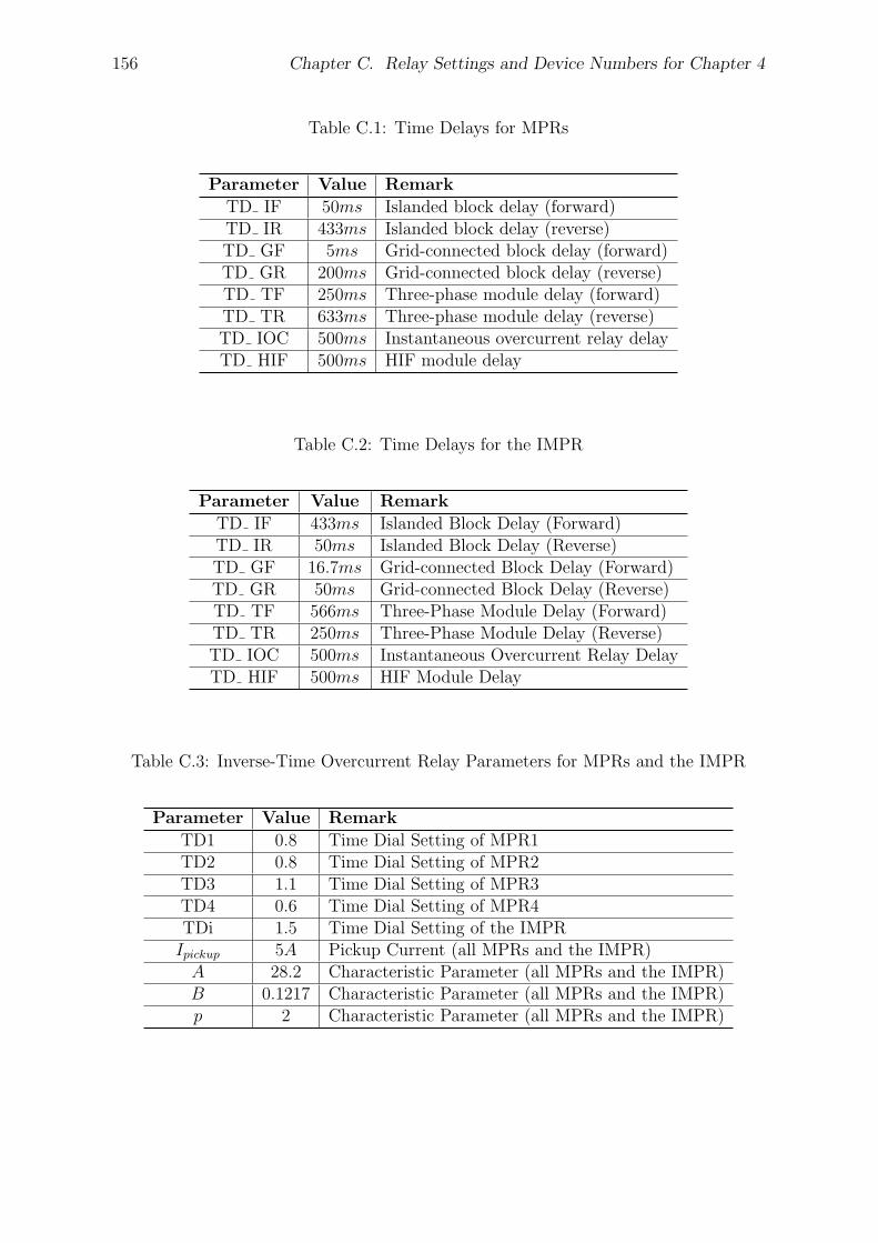
156 Chapter C. Relay Settings and Device Numbers for Chapter 4
Table C.1: Time Delays for MPRs
Parameter Value Remark
TD IF 50ms Islanded block delay (forward)TD IR 433ms Islanded block delay (reverse)TD GF 5ms Grid-connected block delay (forward)TD GR 200ms Grid-connected block delay (reverse)TD TF 250ms Three-phase module delay (forward)TD TR 633ms Three-phase module delay (reverse)TD IOC 500ms Instantaneous overcurrent relay delayTD HIF 500ms HIF module delay
Table C.2: Time Delays for the IMPR
Parameter Value Remark
TD IF 433ms Islanded Block Delay (Forward)TD IR 50ms Islanded Block Delay (Reverse)TD GF 16.7ms Grid-connected Block Delay (Forward)TD GR 50ms Grid-connected Block Delay (Reverse)TD TF 566ms Three-Phase Module Delay (Forward)TD TR 250ms Three-Phase Module Delay (Reverse)TD IOC 500ms Instantaneous Overcurrent Relay DelayTD HIF 500ms HIF Module Delay
Table C.3: Inverse-Time Overcurrent Relay Parameters for MPRs and the IMPR
Parameter Value Remark
TD1 0.8 Time Dial Setting of MPR1TD2 0.8 Time Dial Setting of MPR2TD3 1.1 Time Dial Setting of MPR3TD4 0.6 Time Dial Setting of MPR4TDi 1.5 Time Dial Setting of the IMPRIpickup 5A Pickup Current (all MPRs and the IMPR)A 28.2 Characteristic Parameter (all MPRs and the IMPR)B 0.1217 Characteristic Parameter (all MPRs and the IMPR)p 2 Characteristic Parameter (all MPRs and the IMPR)
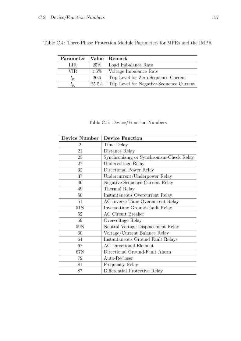
C.2. Device/Function Numbers 157
Table C.4: Three-Phase Protection Module Parameters for MPRs and the IMPR
Parameter Value Remark
LIR 25% Load Imbalance Rate
VIR 1.5% Voltage Imbalance Rate
Ip0 20A Trip Level for Zero-Sequence Current
Ip2 25.5A Trip Level for Negative-Sequence Current
Table C.5: Device/Function Numbers
Device Number Device Function
2 Time Delay
21 Distance Relay
25 Synchronizing or Synchronism-Check Relay
27 Undervoltage Relay
32 Directional Power Relay
37 Undercurrent/Underpower Relay
46 Negative Sequence Current Relay
49 Thermal Relay
50 Instantaneous Overcurrent Relay
51 AC Inverse-Time Overcurrent Relay
51N Inverse-time Ground-Fault Relay
52 AC Circuit Breaker
59 Overvoltage Relay
59N Neutral Voltage Displacement Relay
60 Voltage/Current Balance Relay
64 Instantaneous Ground Fault Relays
67 AC Directional Element
67N Directional Ground-Fault Alarm
79 Auto-Recloser
81 Frequency Relay
87 Differential Protective Relay
Appendix D
Load and Relay Parameters for
Chapter 5
D.1 Network Loads
Table D.1 reports the load of each bus of the study microgrid simulated in Chapter 5.
The blank cells indicate unconnected phases. Other information about the network can
be found in reference [24].
D.2 Relay Signals
Table D.2 shows the definition of the signals and/or parameters that are employed in the
proposed microprocessor-based relay of Chapter 5.
158
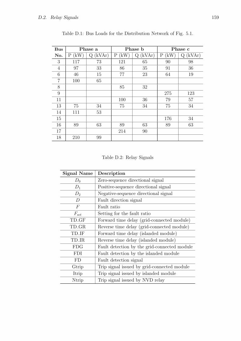
D.2. Relay Signals 159
Table D.1: Bus Loads for the Distribution Network of Fig. 5.1.
Bus Phase a Phase b Phase c
No. P (kW) Q (kVAr) P (kW) Q (kVAr) P (kW) Q (kVAr)
3 117 73 121 65 90 98
4 97 33 86 35 91 36
6 46 15 77 23 64 19
7 100 65
8 85 32
9 275 123
11 100 36 79 57
13 75 34 75 34 75 34
14 111 53
15 176 34
16 89 63 89 63 89 63
17 214 90
18 210 99
Table D.2: Relay Signals
Signal Name Description
D0 Zero-sequence directional signal
D1 Positive-sequence directional signal
D2 Negative-sequence directional signal
D Fault direction signal
F Fault ratio
Fset Setting for the fault ratio
TD GF Forward time delay (grid-connected module)
TD GR Reverse time delay (grid-connected module)
TD IF Forward time delay (islanded module)
TD IR Reverse time delay (islanded module)
FDG Fault detection by the grid-connected module
FDI Fault detection by the islanded module
FD Fault detection signal
Gtrip Trip signal issued by grid-connected module
Itrip Trip signal issued by islanded module
Ntrip Trip signal issued by NVD relay
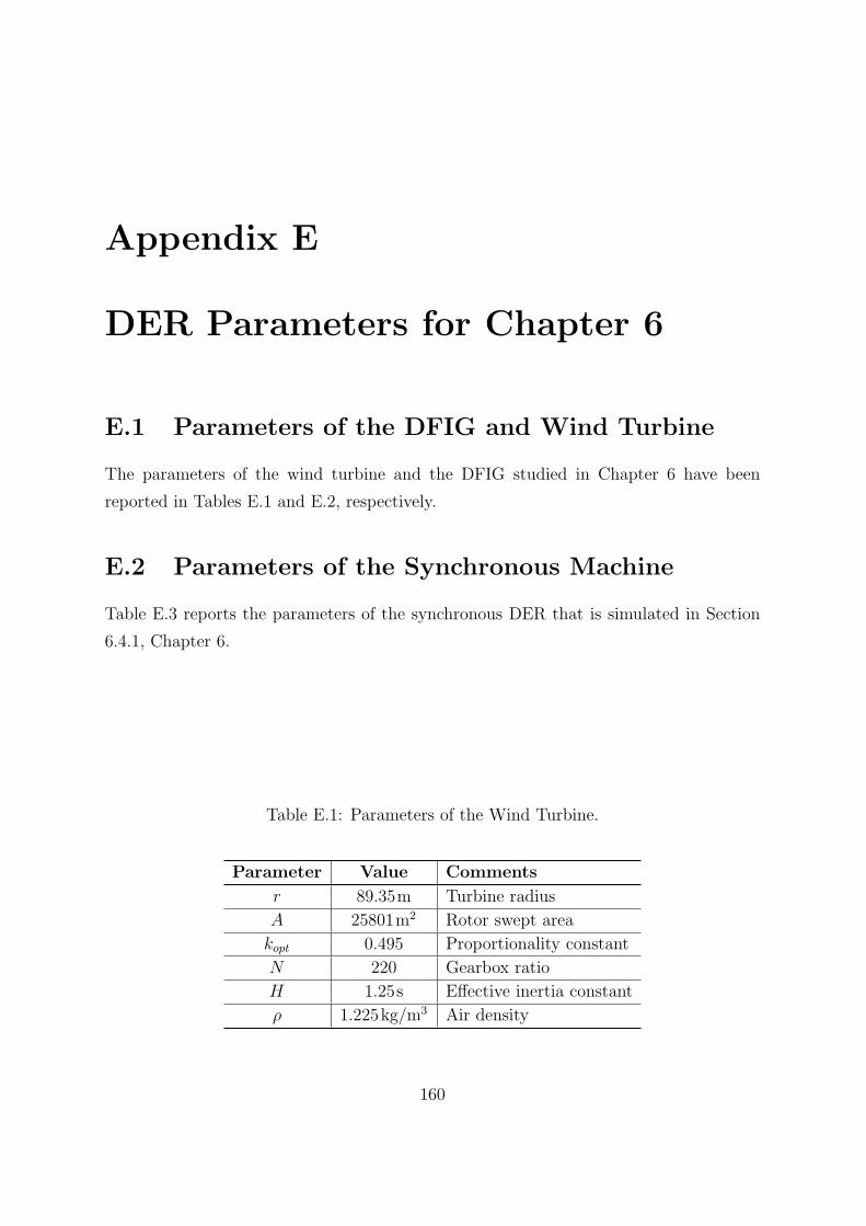
Appendix E
DER Parameters for Chapter 6
E.1 Parameters of the DFIG and Wind Turbine
The parameters of the wind turbine and the DFIG studied in Chapter 6 have been
reported in Tables E.1 and E.2, respectively.
E.2 Parameters of the Synchronous Machine
Table E.3 reports the parameters of the synchronous DER that is simulated in Section
6.4.1, Chapter 6.
Table E.1: Parameters of the Wind Turbine.
Parameter Value Comments
r 89.35m Turbine radius
A 25801m2 Rotor swept area
kopt 0.495 Proportionality constant
N 220 Gearbox ratio
H 1.25s Effective inertia constant
ρ 1.225kg/m3 Air density
160
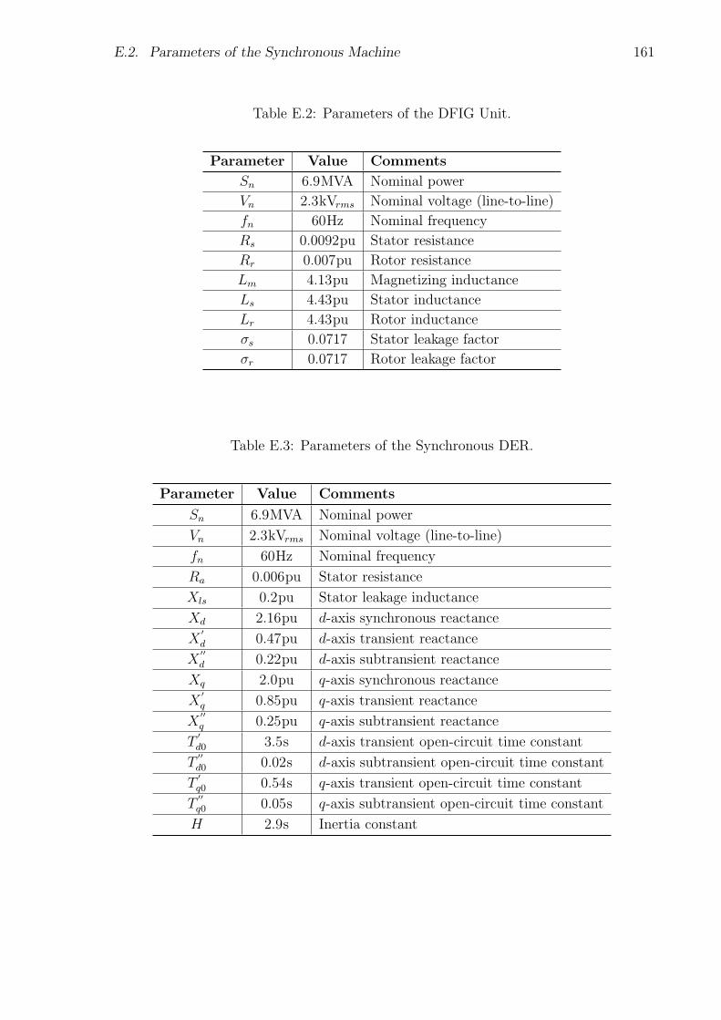
E.2. Parameters of the Synchronous Machine 161
Table E.2: Parameters of the DFIG Unit.
Parameter Value Comments
Sn 6.9MVA Nominal power
Vn 2.3kVrms Nominal voltage (line-to-line)
fn 60Hz Nominal frequency
Rs 0.0092pu Stator resistance
Rr 0.007pu Rotor resistance
Lm 4.13pu Magnetizing inductance
Ls 4.43pu Stator inductance
Lr 4.43pu Rotor inductance
σs 0.0717 Stator leakage factor
σr 0.0717 Rotor leakage factor
Table E.3: Parameters of the Synchronous DER.
Parameter Value Comments
Sn 6.9MVA Nominal power
Vn 2.3kVrms Nominal voltage (line-to-line)
fn 60Hz Nominal frequency
Ra 0.006pu Stator resistance
Xls 0.2pu Stator leakage inductance
Xd 2.16pu d-axis synchronous reactance
X′
d 0.47pu d-axis transient reactance
X′′
d 0.22pu d-axis subtransient reactance
Xq 2.0pu q-axis synchronous reactance
X′q 0.85pu q-axis transient reactance
X′′q 0.25pu q-axis subtransient reactance
T′
d0 3.5s d-axis transient open-circuit time constant
T′′
d0 0.02s d-axis subtransient open-circuit time constant
T′q0 0.54s q-axis transient open-circuit time constant
T′′q0 0.05s q-axis subtransient open-circuit time constant
H 2.9s Inertia constant
Bibliography
[1] R. H. Lasseter, “Microgrids,” in Proc. IEEE Power Engineering Society Winter Meet-
ing, vol. 1, pp. 305-308, Jan. 2009.
[2] N. Hadjsaid, J. F. Canard and F. Dumas, “Disperse generation impact on distribution
network,” IEEE Computer Application in Power, vol. 12, issue 2, pp. 22-28, Apr. 1999.
[3] A. Girgis and S. M. Brahma, “Effect of distributed generation on protective device
coordination in distribution system,” in Proc. Large Engineering Systems Conf. on
Power Engineering, pp. 115-119, Jul. 2001.
[4] H. Nikkhajoei and R. Lasseter, “Microgrid protection,” in Proc. IEEE Power Engi-
neering Soc. General Meeting, pp. 1-6, Jun. 2007.
[5] H. L. Wills and W. G. Scott, Distributed Power Generation, Marcell Dekker, New
York, 2000.
[6] N. Hatziargyriou, H. Asano, R. Iravani, and C. Marnay, “Microgrids,” IEEE Power
and Energy Mag., vol. 5, no. 4, pp. 78-94, Jul./Aug., 2007.
[7] F. Katiraei, R. Iravani, N. Hatziargyriou, and A. Dimeas, “Microgrids management,”
IEEE Power and Energy Mag., vol. 6, no. 3, pp. 54-65, May-Jun. 2008.
[8] Website of the Ministry of Energy (Government of Ontario),
http://www.energy.gov.on.ca/en/
[9] H. Nikkhajoei and R. H. Lasseter, “Distributed generation interface to the CERTS
microgrid,” IEEE Trans. on Power Delivery, vol. 24, no. 3, pp. 1598-1608, Jul. 2009.
[10] F. Katiraei, M. R. Iravani, and P. W. Lehn, “Small-signal dynamic model of a micro-
grid including conventional and electronically interfaced distributed resources,” IIET
Journal on Generation, Transmission & Distribution, vol. 1, no. 3, pp. 369-378, May.
2007.
162
BIBLIOGRAPHY 163
[11] S. Teleke, M. E. Baran, A. Q. Huang, S. Bhattacharya, and L. Anderson, “Control
strategies for battery energy storage for wind farm dispatching,” IEEE Trans. on
Energy Conversion, vol. 24, no. 3, pp. 725-732, Sep. 2009.
[12] F. Katiraei and M. R. Iravani, “Power management strategies for a microgird with
multiple distributed generation units,” IEEE Trans. on Power Systems, vol. 21, no.
4, pp. 1821-1831, November 2006.
[13] B. Kroposki, R. Lasseter, T. Ise, S. Morozumi, S. Papathanassiou, and N. Hatziar-
gyriou, “Making Microgrids Work,” IEEE Power and Energy Mag., vol. 6, no. 3, pp.
40-53, May-Jun. 2008.
[14] A. G. Tsikalakis and N. D. Hatziargyriou, “Centralized control for optimizing mi-
crogrids operation,” IEEE Trans. on Energy Conversion, vol. 23, no. 1, pp. 241-248,
Mar. 2008.
[15] A. L. Dimeas and N. D. Hatziargyriou, “Operation of a multiagent system for mi-
crogrid control,” IEEE Trans. on Power Systems, vol. 20, no. 3, pp. 1447-1455, Aug.
2005.
[16] Y. A. I. Mohamed and E. F. El-Saadany, “Adaptive decentralized droop controller
to preserve power sharing stability of paralleled inverters in distributed generation
microgrids,” IEEE Trans. on Power Electronics, vol. 23, no. 6, pp. 2806-2816, 2008.
[17] J. M. Guerrero, J. Matas, L. G. Vicuna, M. Castilla, and J. Miret, “Decentralized
control for parallel operation of distributed generation inverters in microgrids using
resistive output impedance,” IEEE Trans. on Industrial Electronics, vol. 54, no. 2,
pp. 994-1004, Apr. 2007.
[18] M. C. Chandorkar, D. M. Divan and R. Adapa, “Control of parallel connected
inverters in standalone ac supply systems,” IEEE Trans. on Industry Applications,
vol. 29, no. 1, pp. 136-143, Jan./Feb. 1993.
[19] J. A. Pecas Lopes and C. L. Moreira, “Defining control strategies for microgrids
islanded operation,” IEEE Trans on Power Systems, vol.21, no.2, pp.916-924, May
2006.
[20] A. Yazdani and R. Iravani, Voltage-Sourced Converters in Power Systems: Modeling,
Control, and Applications, Hoboken, NJ: IEEE/Wiley, 2010.
164 BIBLIOGRAPHY
[21] M. P. Kazmierkowski and L. Malesani,“Current-control techniques for three-phase
voltage-source PWM converters: A survey,” IEEE Trans. on Industrial Electronics,
vol. 45, no. 5, pp. 691703, Oct. 1998.
[22] A. Yazdani, A. R. Di Fazio, H. Ghoddami, M. Russo, M. Kazerani, J. Jatskevich,
K. Strunz, S. Leva and J. A. Martinez, “Modeling guidelines and a bechmark for
power system simulation studies of three-phase single-stage photovoltaic systems,”
IEEE Trans. on Power Delivery, vol. 26, no. 2, pp. 1247-1264, Apr. 2011.
[23] P. P. Barker and R. W. de Mello, “Determining the impact of distributed gener-
ation on power systems: part I-radial distribution systems”, in Proc. IEEE Power
Engineering Soc. Summer Meeting, pp. 1645-1656, Jul. 2000.
[24] Cooper Power Systems, Electrical Distribution-System Protection, Cooper Indus-
tries, 3rd Edition, 1990.
[25] IEEE Recommended Practice for Protection and Coordination of Industrial and
Commercial Power Systems, IEEE Std. 242-1986.
[26] Institute of Electrical Engineers, Power System Protection, vol. 1-4, Second Edition,
London, UK, 1995.
[27] S. Chaitusaney and A. Yokoyama, “Impact of protection coordination on sizes of
several distributed generation sources,” in Proc. 7th Intl. Power Engineering Conf.,
vol. 2. pp 669-674, Dec. 2005.
[28] K. Maki, S. Repo, P. Jarventausta, “Methods for assessing the protection impacts
of distributed generation in network planning activities,” in Proc. IET 9th Intl. Conf.
on Developments in Power System Protection, pp. 484-489, Mar. 2008.
[29] M. T. Doyle, “Reviewing the impacts of distributed generation on distribution sys-
tem protection,” in Proc. IEEE Power Engineering Soc. Summer Meeting, vol. 1, pp.
103-105, Jul. 2002.
[30] K. Kauhaniemi, L. Knmpnlained, “Impact of distributed generation on the protec-
tion of distribution networks,” in Proc. Intl. Conf. on Developments in Power System
Protection, vol. 1, pp. 315-318, Apr. 2004.
BIBLIOGRAPHY 165
[31] Y. W. Li, D. M. Vilathgamuwa, and P. C. Loh, “Design, analysis, and realtime
testing of a controller for multibus MicroGrid system,” IEEE Trans. on Power Elec-
tronics, vol. 19, no. 5, pp. 1195-1204, Sep. 2004.
[32] H. Karimi, H. Nikkhajoei and R. Iravani, “Control of an electronically-coupled dis-
tributed resource unit subsequent to an islanding event,” IEEE Trans. on Power
Delivery, vol. 23, no. 1, pp. 493-501, Jan. 2008.
[33] M. B. Delghavi and A. Yazdani, “A Control strategy for islanded operation of a dis-
tributed resource (DR) unit,” in Proc. IEEE Power and Energy Soc. General Meeting,
pp. 1-8, Jul. 2009.
[34] M. B. Delghavi and A. Yazdani, “Islanded-mode control of electronically coupled
distributed-resource units under unbalanced and nonlinear load conditions,” IEEE
Trans. on Power Delivery, vol. 26, no. 2, pp. 661-673, Apr. 2011.
[35] N. Pogaku, M. Prodanovic and T. C. Green, “Modeling, analysis and testing of
autonomous operation of an inverter-based microgrid,” IEEE Trans. on Power Elec-
tronics, vol. 22, no. 2, pp. 613-625, Mar. 2007.
[36] J. C. Vasquez, J. M. Guerrero, A. Luna, P. Rodrguez and R. Teodorescu, “Adaptive
droop control applied to voltage-source inverters operating in grid-connected and
islanded modes,” IEEE Trans. on Industry Applications, vol. 56, no. 10, pp. 4088-
4096, Oct. 2009.
[37] R. Majumder, B. Chaudhuri, A. Ghosh, R. Majumder, G. Ledwich and F. Zare,
“Improvement of stability and load sharing in an autonomous microgrid using sup-
plementary droop control loop,” IEEE Trans. on Power Systems, vol. 25, no. 2, pp.
796-808, May 2010.
[38] R. Majumder, G. Ledwich, A. Ghosh, S. Chakrabarti and F. Zare, “Droop control
of converter-interfaced microsources in rural distributed generation,” IEEE Trans. on
Power Delivery, vol. 25, no. 4, pp. 2768-2778, Oct. 2010.
[39] Y. Li, D. M. Vilathgamuwa and P. C. Loh, “Microgrid power quality enhancement
using a three-phase four-wire grid-interfacing compensator,” IEEE Trans. on Industry
Applications, vol. 41, no. 6, pp. 1707-1719, Nov./Dec. 2005.
166 BIBLIOGRAPHY
[40] Y. W. Li, D. M. Vilathgamuwa and P. C. Loh, “A grid-interfacing power qual-
ity compensator for three-phase three-wire microgrid applications,” IEEE Trans. on
Power Electronics, vol. 21, no. 4, pp. 1021-1031, Jul. 2006.
[41] M. Prodanovic and T. C. Green, “High-quality power generation through distributed
control of a power park microgrid,” IEEE Trans. on Industrial Electronics, vol. 53,
no. 5, pp. 1471-1482, Oct. 2006.
[42] T. C. Green and M. Prodanovic, “Control of inverter-based micro-grids,” Intl. Jour-
nal of Electric Power Systems Research, vol. 77, issue 9, pp. 1204-1213, Jul. 2007.
[43] M. Prodanovic, T. C. Green and H. Mansir, “A survey of control methods for three-
phase inverters in parallel connection,” in Proc. IEE intl. Conf. on Power Electronics
and Variable Speed Drives, no. 475, pp. 472-477, Sep. 2000.
[44] M. S. Khan and R. Iravani, “Supervisory hybrid control of a micro grid system,” in
Proc. IEEE Electrical Power Conf., pp. 20-24, Oct. 2007.
[45] S. Mizani and A. Yazdani, “Design and operation of a remote microgrid,” in proc.
35th IEEE Conf. on Industrial Electronic, pp. 4299-4304, Nov. 2009.
[46] R. Majumder, A. Ghosh, G. Ledwich, S. Chakrabarti and F. Zare, “Improved power
sharing among distributed generators using web based communication,” in Proc.
IEEE Power and Energy Soc. General Meeting, pp. 1-8, Jul. 2010.
[47] C. A. Plet, M. Graovac, T. C. Green and R. Iravani, “Fault response of grid-
connected inverter dominated networks,” in Proc. IEEE Power and Energy Soc. Gen-
eral Meeting, pp. 1-8, Jul. 2010.
[48] P. Rodrigues, A. V. Timbus, R. Teodorescu, M. Liserre and F. Blaabjerg, “Flexible
active power control of distributed power generation systems during grid faults,”
IEEE Trans. on Industrial Electronics, vol. 54, no. 5, pp. 2853-2592, Oct. 2007.
[49] A. V. Timbus, R. Teodorescu, M. Liserre, and P. Rodrequez, “PLL Algorithm for
Power Generation Systems Robust to Grid voltage Faults,” in Proc. IEEE 37th Power
Electronic Specialists Conf., pp. 1-7, Jun. 2006.
[50] A. V. Timbus, P. Rodriguez, R. Teodorescu, M. Liserre and F. Blaabjerg, “Control
strategies for distributed power generation systems operating on faulty grid,” in Proc.
IEEE International Symp. on Industrial Electronics, pp. 1601-1607, Jul. 2006.
BIBLIOGRAPHY 167
[51] F. Katiraei, M. R. Iravani and W. Lehn, “Micro-grid autonomous operation during
and subsequent to islanding process,” IEEE Trans. on Power Delivery, vol. 20, no.
1, pp. 248-257, Jan. 2005.
[52] S. M. Brahma and A. Girgis, “Microprocessor-based reclosing to coordinate fuse and
recloser in a system with high penetration of distributed generation,” in Proc. IEEE
Power Engineering Soc. Winter Meeting, vol. 1, pp. 453-458, Jan. 2002.
[53] G. Tang and M. R. Iravani, “Application of a fault current limiter to minimize
distributed generation impact on coordinated relay protection,” in Proc. Intl. Conf.
Power Systems Transients, pp. 1-6, Jun. 2005.
[54] W. El-Khattam and T. S. Sidhu, “Restoration of directional overcurrent relay co-
ordination in distributed generation systems utilizing fault current limiter,” IEEE
Trans. on Power Delivery, vol. 23, no. 2, pp. 576-585, Apr. 2008.
[55] S. M. Brahma and A. A. Girgis, “Development of adaptive protection scheme for
distribution systems with high penetration of distributed deneration,” IEEE Trans.
on Power Delivery, vol. 19, no. 1, pp. 5663, Jan. 2004.
[56] H. Wan, K. K. Li, and K. P.Wong, “A multi-agent approach to protection relay
coordination with distributed generators in industrial power distribution system,” in
Proc. 40th Industrial Application Soc. Annu. Meeting, pp. 830836, Oct. 2005.
[57] B. Hadzi-Kostova and Z. Styczynski, “Network protection in distribution systems
with dispersed generation,” in Proc. Transmission Distribution Conf., pp. 16, May
2006.
[58] B. Li, Y. Li, Z. Bo, and A. Kilmek, “Design of protection and control scheme for
microgrid systems,” in Proc. 44th Intl. University Power Engineering Conf., pp. 15,
Sep. 2009.
[59] M. Dewadasa, R. Majumder, A. Ghosh and G. Ledwitch, “Control and protection
of a microgrid with converter interfaced micro sources,” in Proc. 3rd Intl. Conf. on
Power Systems, pp. 1-6, Dec. 2009.
[60] E. Sortomme, G. J. Mapes, B. A. Foster and S. S. Venkata, “Fault analysis and
protection of a microgrid,” in Proc. 40th North American Power symp., pp. 1-6, Sep.
2008.
168 BIBLIOGRAPHY
[61] H.H. Zeineldin, E. F. El-Saadany and M. M. A. Salama, “Distributed generation
micro-grid operation: control and protection,” in Proc. Power System Conf., pp.
105-112, Mar. 2006.
[62] E. Sortomme, S.S. Venkata and J. Mitra, “Microgrid protection using
communication-assisted digital relays,” IEEE Trans. on Power Delivery, vol. 25, no.
4, pp. 2789-2796, Oct. 2010.
[63] R. M. Tumilty, M. Brucoli and T. C. Green, “Approaches to network protection for
inverter dominated electrical distribution systems,” in Proc. 3rd IET Intl. Conf. on
Power Electronics, Machines, and Drives, pp. 622-626, Apr. 2006.
[64] H. Al-Nasseri, M. Redfern and F. Li, “A voltage based protection for micro-grids
containing power electronic converters,” in Proc. IEEE Power Engineering Society
General Meeting, pp. 1-7, Jun. 2006.
[65] M. A. Redfern and H. Al-Nasseri, “Protection of micro-grids dominated by dis-
tributed generation using solid state converters,” in Proc. 9th Intl. IET Conf. on
Developments in Power System Protection, pp. 670-674, Mar. 2008.
[66] T. Loix, T. Wijnhoven and G. Deconinck, “Protection of microgrids with a high
penetration of inverter-coupled energy sources,” in Proc. IEEE PES/CIGRE Symp.,
pp. 1-6, Jun. 2009.
[67] N. Jayawarna, C. Jones, M. Barnes and N. Jenkins, “Operating microGrid energy
storage control during network faults,” in Proc. IEEE Intl. Conf. on System of Sys-
tems Engineering, pp. 1-7, Apr. 2007.
[68] N. Jayawarna, N. Jenkins, M. Barnes, M. Lorentzou, S. Papthanassiou and N.
Hatziargyriou, “Safety analysis of a microgrid,” in Proc. the Intl. Conf. on Future
Power Systems, pp. 1-7, Nov. 2005.
[69] PSCAD/EMTDC V. 4.2, Manitoba HVDC Research Center, Winnipeg, MB,
Canada
[70] M. H. J. Bollen, Understanding Power Quality Problems: Voltage Sags and Inter-
ruptions, New York, NY: IEEE Press, 2000.
BIBLIOGRAPHY 169
[71] G. Yalcinkaya, M. H. J. Bollen and P. Crossley, “Characterization of Voltage Sags
in Industrial Distribution Systems”, IEEE Trans. on Industry Applications, vol. 34,
no. 4, pp. 682-688, Jul./Aug. 1998
[72] L. Zhang and M. H. J. Bollen, “Characteristic of Voltage Dips (Sags) in Power
Systems”, IEEE Trans. on Power Delivery, vol. 15, no. 2, pp. 827-832, Apr. 2000
[73] H. Song and K. Nam, “Dual current control scheme for PWM converter under
unbalanced input voltage conditions,” IEEE Trans. on Industrial Electronics, vol. 46,
no. 5, pp. 953-959, Oct. 1999.
[74] A. Yazdani and M. R. Iravani, “A unified dynamic model and control for the voltage
source converter under unbalance grid condition,” IEEE Trans. on Power Delivery,
vol. 21, no. 3, pp. 1620-1629, Jul. 2006.
[75] S. K. Chung, “A phase tracking system for three phase utility interface inverters,”
IEEE Trans. on Power Electronics, vol. 15, no. 3, pp. 431-438, May 2000.
[76] IEEE Application Guide for IEEE Standard for Interconnecting Distributed Re-
sources with Electric Power Systems, IEEE Std. 1547.2-2008.
[77] K. Strunz, R. H. Fletcher, R. Campbell and F. Gao, “Developing benchmark models
for low-voltage distribution feeders”, in Proc. IEEE Power and Energy Soc. General
Meeting, pp. 1-3, Jul. 2009.
[78] S. Papathanassiou, N. Hatziargyriou and K. Strunz, “A benchmark low voltage
microgrid network,” CIGRE Symposium, pp. 1-8, Apr. 2005.
[79] S. Chiniforoosh, J. Jatskevic, A. Yazdani, V. Sood, V. Dinavahi, J. A. Martinez and
A. Ramirez, “Definitions and applications of dynamic average models for analysis of
power systems,” IEEE Trans. on Power Delivery, vol. 25, no. 4, pp. 2655-2669, Oct.
2010.
[80] IEEE Recommended Practices and Requirements for Harmonic Control in Electrical
Power Systems, IEEE Std. 519-1992.
[81] IEEE Recommended Practice for Industrial and Commercial Power System Analysis,
IEEE Std. 399-1997.
170 BIBLIOGRAPHY
[82] S. Santoso and T. A. Short, “Identification of fuse and recloser operations in a radial
distribution systems,” IEEE Trans. on Power Delivery, vol. 22, no. 4, pp. 2370-2377,
Oct. 2007.
[83] IEEE Standard Inverse-Time Characteristic Equations for Over-current Relays,
IEEE Std. C37.112-1996, Sep. 1996.
[84] ABB Group Inc., ABB PCD Control Protection Curves, online available:
http://www.abb.com.
[85] T. S. M. Rao, Power System Protection: Static Relays with Microprocessor Appli-
cations, 2nd Edition, New Delhi: Tata Mc. Graw-Hill, 1989.
[86] T. Gonen, Electric Power Distribution System Engineering, 2nd Edition, Boca Ra-
ton, FL: CRC press, 2008.
[87] Westinghouse Electric Corporation, Electric Utility Engineering Reference Book:
Distribution Systems, vol. 3, East Pittsburgh, PA, 1965.
[88] R. Calvas and B. Lacroix, System Earthing in LV, Schneider Electric, Cahier Tech-
nique no. 172, 2000.
[89] E. Lakervi and E. J. Holmes, Electricity Distribution Network Design, IEE Power
Engineering Series 21, Peter Peregrinus Ltd., 2nd Edition, London, UK, 1995.
[90] British Standard Fuses BS 1361-3, online available:
http://en.wikipedia.org/wiki/BS 1362, & http://en.wikipedia.org/wiki/Fuse electrical.
[91] Ferraz Shawmut, LV Fuse Link and Holder Catalogues, online available:
http://us.ferrazshawmut.com.
[92] IEEE Recommended Practice for Monitoring Electric Power Quality, IEEE Std.
1159-2009.
[93] R. C. Christie, H. Zadehgol and M. M. Habib, “High impedance fault detection in
low voltage netwoks”, IEEE Trans. on Power Delivery, vol. 8, no. 4, pp. 1829-1836,
Oct. 1993.
[94] B. M. Aucoin and B. D. Russell, “Distribution high impedance fault detection uti-
lizing high frequency current components”, IEEE Trans. on Power Apparatus and
Systems, vol. 101, no. 6, pp. 1596-1606, Jun. 1982.
BIBLIOGRAPHY 171
[95] D. I. Jeerings and J. R. Linders, “Unique aspects of distribution system harmonics
due to high impedance ground faults”, IEEE Trans. on Power Delivery, vol. 5, no. 2,
pp. 1086-1094, Apr. 1990.
[96] General Electric Multilin Inc., Instruction Manual for D60 Line Distance Protection
System, online available: http://www.gedigitalenergy.com.
[97] J. Roberts and A. Guzman, “Directional element design and evaluation”, in Proc.
21st Annual Western Protective Relay Conf., pp. 1-27, 1994.
[98] Qual-Tech Engineers Inc., Overcurrent Coordination Guidlines for Industrial Power
Systems, online available: http://www.qualtecheng.com/PDF/QT-608-1009.pdf
[99] CEE Relays Ltd., Connection and Setting of Neutral Voltage Displacement (NVD)
Relays, online available: http://www.ceerelays.co.uk/RelayFAQs/NVD.htm.
[100] A. T. Johns and S. K. Salman, Digital Protection for Power Systems, IEE Power
Engineering Series 15, Peter Peregrinus Ltd., London, UK, 1995.
[101] Schweitzer Engineering Laboratories, SEL-751A Feeder Protection Relay, online
available at: www.selinc.com/WorkArea/DownloadAsset.aspx?id=2822.
[102] IEEE Standard for Electrical Power System Device Function Numbers, Acronyms,
and Contact Designations, IEEE Std. C37.2-2008.
[103] B. Jianguang, D. Xinzhou, G. Yongji and B. Zhiqian, “Research on non-
communication protection of distribution lines based on fault components,” in Proc.
intl. Conf. on Power System Technology, pp. 1151-1155, Oct. 2002.
[104] J. D. Glover and M. S. Sarma, Power System Analysis and Design, 3rd Edition,
Pacific Grove, CA: Brooks/Cole, 2002.
[105] G. Benmouyal and J. Roberts, “Superimposed quantities: Their true nature and
applications in relays,” Schweitzer Engineering Laboratories, Inc., pp. 1-18, 1999.
[106] M. R. Iravani and M. Karimi-Ghartemani, “Online estimation of steady state and
instantaneous symmetrical components,” IET Journal on Generation, Transmission
& Distribution, vol. 150, no. 5, pp. 616-622, Sep. 2003.
172 BIBLIOGRAPHY
[107] Z. Q. Bo, “Adaptive non-communication protection for power lines BO scheme1-
The delayed operation approach,” IEEE Trans. on Power Delivery, vol. 17, no. 1, pp.
85-91, Jan. 2002.
[108] Z. Gan, X. Z. Dong, Z. Q. Bo, B. R. J. Caunce and D. Montjean, “A new protection
scheme for high impedance fault using adaptive trip and reclosure technique,” in Proc.
Intl. Conf. on Power system Technology, pp. 295-299, Oct. 2002.
[109] Y. C. Lee, “Effects of Unbalanced Voltage on the Operation Performance of a
Three-phase Induction Motor,” IEEE Trans. on Energy Conversion, vol. 14, no. 2,
pp. 202-208, Jun. 1999.
[110] LONGO Inc., Unbalanced voltages and electric motors: causes and consequences,
onnline available: http://www.elongo.com/pdfs/voltages.PDF.
[111] B. Meyer, “Directional ground and sensitive ground fault settings,” Cooper Power
Systems, Cooper industries, pp. 1-17, Feb. 2004.
[112] P. P. Parikh, M. G. Kanabar and T. S. Sidhu, “Opportunities and challenges of wire-
less communication technologies for smart grid applications”, in Proc. IEEE Power
and Energy Society General Meeting, pp. 1-7, Jul. 2010.
[113] IEEE Standard for Information Technology, Telecommunications and Information
Exchange between Systems, Local and Metropolitan Area Networks, IEEE Std. 802.11-
2007.
[114] AFAR Communications Inc., Outdoor long range industrial wireless Ethernet
Bridge, online available: http://www.afar.net/wireless/ethernet-bridge/.
[115] S. Ekles, Detecting High-Impedance Faults, El-Paso Electric Inc., online avail-
able: http://www.pennenergy.com/index/power/display/341599/articles/utility-
automation-engineering-td/volume-13/issue-10/features/detecting-high-impedance-
faults.html
[116] P. Kundur, Power System Stability and Control, McGraw Hill, 1994.
[117] W. F. Horton, S. Goldberg and C. A. Volkmann, “The failure rates of overhead
distribution system components,” in Proc. Power Engineering Society Transmission
and distribution Conf., pp. 713-717, Sep. 1991.
BIBLIOGRAPHY 173
[118] J. C. Cebrian and N. Kagan, “Hybrid method to assess sensitive process inter-
ruption costs due to faults in electric power distribution networks,” IEEE Trans. on
Power Delivery, vol. 25, no. 3, pp. 1686-1696, Jul. 2010.
[119] F. Roos and S. Lindah, “Distribution system component failure rates and repair
times-An overview,” in Proc. Distribution and Asset Management Conf., pp. 1-6,
Aug. 2004.
[120] Y. M. Atwa and E. F. El-Saadany, “Reliability evaluation for distribution system
with renewable distributed generation during islanded mode of operation,” IEEE
Trans. on Power Systems, vol. 24, no. 2, pp. 572-581, May 2009.
[121] Canadian Wind Energy Association, Online available: http://www.canwea.ca.
[122] SIEMENS Product Brochure, online available:
http://www.energy.siemens.com/hq/pool/hq/power-generation/renewables/wind-
power/6 MW Brochure Jan.2012.pdf.
[123] Canadian Wind Energy Atlas, online available:
http://www.windatlas.ca/en/maps.php.
[124] F. A. Bhuiyan and A. Yazdani, “Multimode control of a DFIG-based wind-power
unit for remote applications,” IEEE Trans. on Power Delivery, vol. 24, no. 4, pp.
2079-2089, Oct. 2009.
[125] J. G. Slootweg, H. Polinder and W. L. Kling, “Representing wind turbine electrical
generating systems in fundamental frequency simulations,” IEEE Trans. on Energy
Conversion, vol. 18, no. 4, pp. 516-524, Dec. 2003.
[126] S. Chaitusaney and A. Yokoyama, “Prevention of reliability degradation from
recloser-fuse miscoordination due to distributed generation,” IEEE Trans. on Power
Delivery, vol. 23, no. 4, pp. 2545-2554, Oct. 2008.
[127] A. F. Naiem, Y. Hegazy, A. Y. Abdelaziz and M. A. Elsharkawy, “A classifica-
tion technique for recloser-fuse coordination in distribution systems with distributed
generation,” IEEE Trans. on Power Delivery, vol. 27, no. 1, pp. 176-185, Jan. 2012.
[128] M. Kim, S. Lim and J. Kim, “Improvement of recloser-fuse operations and coordi-
nation in a power distribution system with SFCL,” IEEE Trans. on Applied Super-
conductivity, vol. 21, no. 3, pp. 2209-2212, Jun. 2011.

Curriculum Vitae
Name: Mohammad Amin Zamani
Post-Secondary University of Western Ontario
Education and London, ON, Canada
Degrees: 2009 - 2012, Ph.D. in Electrical Engineering
Shahid Chamran University
Ahvaz, Iran
2003 - 2005, M.Sc. in Electrical Engineering
Iran University of Science and Technology
Tehran, Iran
1999 - 2003, B.Sc. in Electrical Engineering
Honours and • Queen Elizabeth II Graduate Scholarships in Science and Technology, 2012.
Awards: • Western Graduate Research Scholarship, since Jan. 2009.
• First Award for the best presentation in the Western Graduate Symposium,2012 & 2011 (twice).
• University Teaching Award of Excellence, Azad University of Abadan, 2007.
• University Excellent Researcher Award, Shahid Chamran University, 2005.
• Ranked 1st in the Power Systems Engineering Group, Shahid Chamran Univer-sity, 2005.
• Excellent Student Award in 3 semesters (out of 8), Iran University of Scienceand Technology.
Related Work • Research and Teaching Assistant, University of Western Ontario, 2009-2012.
Experience: • Teaching Assistant, University of Waterloo, Summer 2011.
• Faculty Member and Head of the Electrical Engineering Department, AzadUniversity of Abadan, Iran, 2005-2009.
• Consulting Engineer, National Iranian Oil Company, Iran, 2008-2009.
• Adjunct Instructor, Petroleum University of Technology, Iran, 2008-2009.
• Instructor, University of Applied Science and Technology, Iran, 2004-2005.
174
BIBLIOGRAPHY 175
Publications:
Peer-Reviewed Journals:
• M. A. Zamani, A. Yazdani and T. S. Sidhu, “A communication-assisted protection strategy for
inverter-based medium-voltage microgrids,” accepted for publication in IEEE Trans. on Smart
Grid, 12 pages, Nov. 2012.
• M. A. Zamani, A. Yazdani and T. S. Sidhu, “A control strategy for enhanced operation of inverter-
based microgrids under transient disturbances and network faults,” IEEE Trans. on Power De-
livery, vol. 27, no. 4, pp. 1737-1747, Oct. 2012.
• M. A. Zamani, T. S. Sidhu and A. Yazdani, “A protection strategy and microprocessor-based
relay for low-voltage microgrids,” IEEE Trans. on Power Delivery, vol. 26, no. 3, pp. 1873-1883,
Jul. 2011.
Referred Conferences:
• M. A. Zamani, A. Yazdani and T. S. Sidhu, “Investigations into the operation of an existing
medium-voltage distribution feeder as a microgrid,” in Proc. IET Renewable Power Generation
Conf., 6 pages, Sep. 2011.
• M. A. Zamani, T. S. Sidhu and A. Yazdani, “A strategy for protection coordination in radial
distribution networks with distributed generators,” in Proc. IEEE Power and Energy Society
General Meeting, 8 pages, Jul. 2010.
• M. A. Zamani, M. Joorabian and A. Yazdani, “C-type filter design based on power factor cor-
rection for 12-pulse HVDC converters,” in Proc. 34th Annual Conf. of the IEEE Industrial
Electronics Society, pp. 3039-3044, Nov. 2008.
• M. Moghaddasian, M. A. Zamani and R. Kiani, “A direct torque control method for dual three
phase induction motors using an adaptive Neuro-Fuzzy controller,” in Proc. 40th North American
Power Symp., 6 pages, Sep. 2008.
• M. Mohseni, M. A. Zamani and M. Joorabian, “Harmonic components identifications through the
Adaline with Fuzzy learning parameters,” in Proc. 33rd Annual Conf. of the IEEE Industrial
Electronics Society, pp. 2515-2520, Nov. 2007.
• M. A. Zamani and M. Mohseni, “Damped-type double tuned filters design for HVDC systems,”
in Proc. 9th International Conf. on Electrical Power Quality and Utilization, 6 pages, Oct. 2007.
• M. Joorabian, S. G. Seifossadat and M. A. Zamani, “An algorithm to design harmonic filters
based on power factor correction for HVDC system,” in Proc. IEEE International Conf. on
Industrial Technology, 6 pages, Dec. 2006.