Embed Size (px)
Citation preview

80386Protected mode Registers, Protection
and Address Translation

System Registers
• GDTR (Global Descriptor Table Register)• IDTR (Interrupt Descriptor Table Register) • LDTR ( Local Descriptor Table Register )• CR0 - CR3 ( Control Registers )• TR ( Task Register)• DR0 - DR7 (Debug Registers)• TR6 - TR7 (Test Registers)

GDTR and IDTR
• These registers hold:–32-bit linear base address and– 16-bit limit of GDT and IDT
respectively. • GDT segments are global to all tasks in
the system.• IDT is used to locate Gates in
Interrupt/Exception handling.

LDTR
• LDTR ( Local Descriptor Table Register ) is a 16-bit register always points to GDT to access LDTD ( Local Descriptor Table Descriptor ) in turn responsible for allocating and accessing local memory via LDT( Local Descriptor Table ).
Control Registers
• Intel386 DX has three control registers of 32 bits, CR0, CR2 and CR3, to hold machine state of a global nature
• These registers along with System Address Registers hold machine state that affects all tasks in the system.
• To access Control Registers, load and store instructions are defined.

Control Register (CR0)

CR0 : Machine Control Register
• CR0 contains 6 defined bits for control and status purposes.
• The low-order 16 bits of CR0 is defined as Machine Status Word
• To operate only on the low-order 16-bits of CR0, LMSW and SMSW instructions are used.
• For 32-bit operations the system should use MOV CR0, Reg instruction.

CR0 : Machine Control Register
• PG (Paging Enable, bit 31):the PG bit is set to enable the on-chip paging unit. It is reset to disable the on-chip paging unit.
• R (reserved, bit 4):This bit is reserved by Intel. When loading CR0 care should be taken to not alter the value of this bit.

CR0 : Machine Control Register
• (TS Bit, Task Switched) : TS is automatically set whenever a task switch operation is performed.
• (EM Bit, Emulate Coprocessor) : This bit is set to cause all coprocessor opcodes to generate a Coprocessor Not Available fault (exception 7).
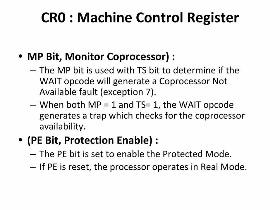
CR0 : Machine Control Register
• MP Bit, Monitor Coprocessor) :– The MP bit is used with TS bit to determine if the
WAIT opcode will generate a Coprocessor Not Available fault (exception 7).
– When both MP = 1 and TS= 1, the WAIT opcode generates a trap which checks for the coprocessor availability.
• (PE Bit, Protection Enable) : – The PE bit is set to enable the Protected Mode. – If PE is reset, the processor operates in Real Mode.

Control Registers
• CR1 : Reserved :CR1 is reserved for use in future Intel processors
• CR2 : Page Fault Linear Address:CR2 holds the 32-bit linear address that caused the last page fault detected.

Control Registers• CR3 : Page Directory Base Address:• physical base address of the page directory
table, always page-aligned (4 Kbyte-aligned). • Thus the lowest twelve bits of CR3 are
ignored.• A task switch through a TSS invalidates all
page table entries in paging unit cache.
Debug Registers
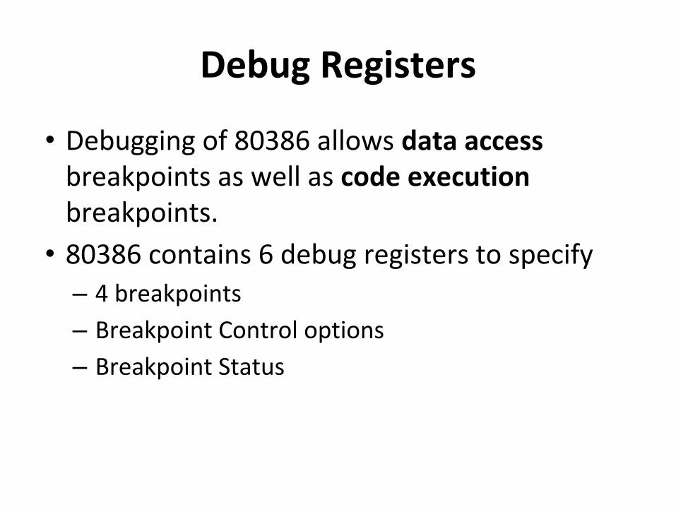
• Debugging of 80386 allows data access breakpoints as well as code execution breakpoints.
• 80386 contains 6 debug registers to specify – 4 breakpoints– Breakpoint Control options– Breakpoint Status
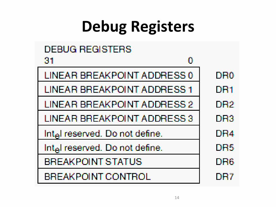
Debug Registers
14
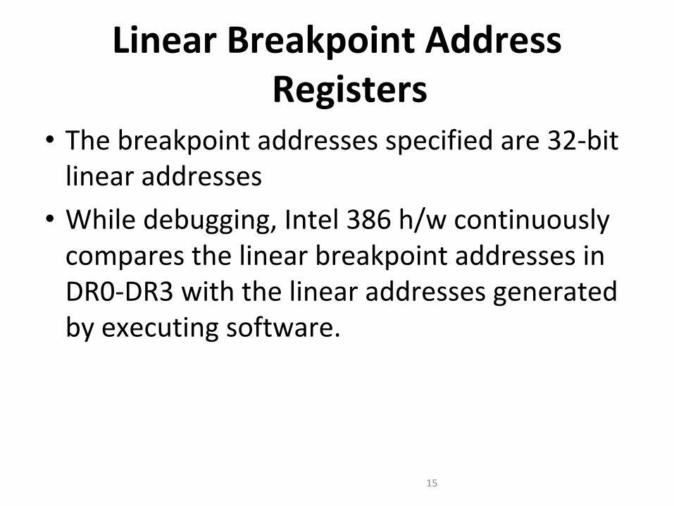
Linear Breakpoint Address Registers
• The breakpoint addresses specified are 32-bit linear addresses
• While debugging, Intel 386 h/w continuously compares the linear breakpoint addresses in DR0-DR3 with the linear addresses generated by executing software.
15
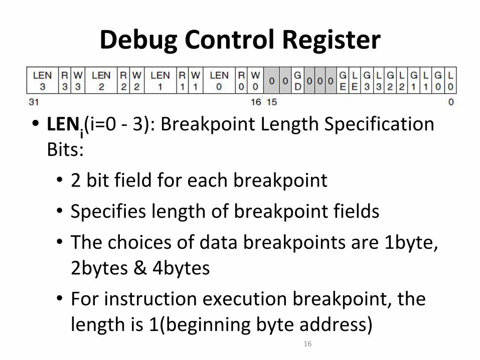
Debug Control Register
• LENi(i=0 - 3): Breakpoint Length Specification Bits:• 2 bit field for each breakpoint• Specifies length of breakpoint fields• The choices of data breakpoints are 1byte,
2bytes & 4bytes• For instruction execution breakpoint, the
length is 1(beginning byte address)16
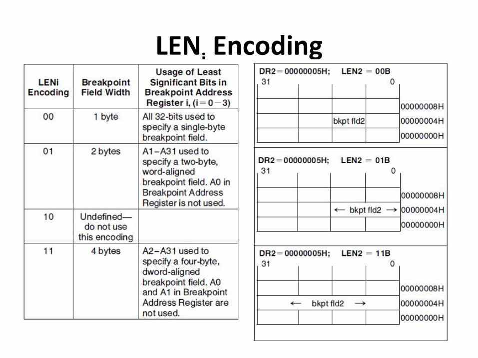
LENi Encoding

Debug Control Register
• RWi(i=0 - 3): Memory Access Qualifier Bit• 2 bit field for each breakpoint• Specifies the type of usage which must
occur inorder to activate the associated breakpoint
18

Debug Registers
19

Debug Control Register
• GD: Global Debug Register Access Detect• Debug registers can only be accessed in real
mode or at privilege level 0 in protected mode
• GD bit, when set, provides extra protection against any Debug Register access even in Real Mode or at privilege level 0 in Protected Mode.
20
Debug Control Register• GD: Global Debug Register Access Detect
• This additional protection feature is provided to guarantee that a software debugger can have full control over the Debug Register resources when required.
• The GD bit, when set, causes an exception 1 fault if an instruction attempts to read or write any Debug Register.
• The GD bit is then automatically cleared when the exception 1 handler is invoked, allowing the exception 1 handler free access to the debug registers. 21

Debug Control Register
• GE and LE bit: Exact data breakpoint match, global and local• If either GE or LE is set, any data breakpoint trap will
be reported exactly after completion of the instruction that caused the operand transfer.
• LE bit is cleared during task switch and is used for task-local breakpoints.
• GE bit is unaffected during a task switch and remain enabled during all tasks executing in the system.
22

Debug Control Register
• Gi and Li(i=0 - 3): Breakpoint Enable, global and local• If either Gi and Li is set then the associated
breakpoint is enabled.
23

Debug Status Register• A Debug Status Register allows the exception 1
handler to easily determine why it was invoked.
• It can be invoked as a result of one of several events:1) DR0 Breakpoint fault/trap.2) DR1 Breakpoint fault/trap.3) DR2 Breakpoint fault/trap.4) DR3 Breakpoint fault/trap.5) Single-step (TF) trap.6) Task switch trap.7) Fault due to attempted debug register access when GD = 1.

Debug Status Register
• Bi : Debug fault/trap due to breakpoint 0 -3• Four breakpoint indicator flags, B0-B3,
correspond one-to-one with the breakpoint registers in DR0-DR3.
• A flag Bi is set when the condition described by DRi, LENi, and RWi occurs.
25

Debug Status Register
• BD : Debug fault due to attempted register access when GD bit is set• This bit is set if the exception 1 handler was
invoked due to an instruction attempting to read or write to the debug registers when GD bit was set.
26
Debug Status Register
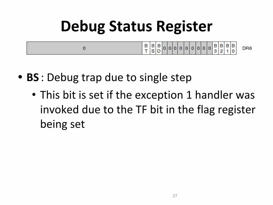
• BS : Debug trap due to single step• This bit is set if the exception 1 handler was
invoked due to the TF bit in the flag register being set
27

Debug Status Register
• BT : Debug trap due to task switch• This bit is set if the exception 1 handler was
invoked due to a task switch occurring to a task having an Intel386 DX TSS with the T bit set.
28
Test Register
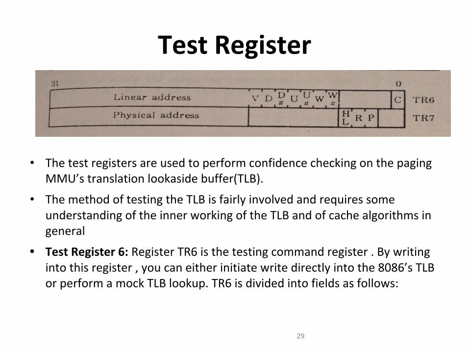
• The test registers are used to perform confidence checking on the paging MMU’s translation lookaside buffer(TLB).
• The method of testing the TLB is fairly involved and requires some understanding of the inner working of the TLB and of cache algorithms in general
• Test Register 6: Register TR6 is the testing command register . By writing into this register , you can either initiate write directly into the 8086’s TLB or perform a mock TLB lookup. TR6 is divided into fields as follows:
29

Test Register• C (Command , Bit 0) : When this bit is cleared , a write to the TLB is
performed . If it is set , the processor performs TLB lookup . The next 7 bits are used to tag attributes for TLB cache , either when writing a new entry or when performing a TLB lookup.
• W# : Not writeable , bit 5• W : writeable, bit 6• U# : Not user , bit 7• U : User , bit 8• D# : Not dirty , bit 9• D : Dirty , bit 10• V : Valid , bit 11• Linear Address(Bits 12 through 31) : This serves as the upper 20 bits of a
linear to be used for TLB references.
30

Test Register• Test Register 7 : TR7 is the TLB testing data register . When a program is
performing writes , the entry to be stored is contained in this register , along with cache set information .
• RP(Replacement pointer , bit 2 and 3): This field indicates which set of TLBs 4 way set associative cache to write to.
• H(pointer location , bit 4): If this bit is set the RP field determines which cache set to write to . If it is cleared , the set is determined with an internal algorithm.
• Physical Address (bit 12 through 31): This field contains either physical address to be written into the TLB or the results of a valid TLB hit
31

Privilege Levels
Highest
Lowest
00: Highest Privilege011011: Lowest Privilege

Privilege levels
• The need is to prevent– Users from interfering with one another– Users from examining secure data– Program bugs from damaging other programs– Program bugs from damaging data– Malicious attempts to compromise system
integrity– Accidental damage to data
Privilege Protection
• Continuous checking by the processor on whether the application is privileged enough to– Type 1: Execute certain instructions– Type 2: Reference data other than its own– Type 3: Transfer control to code other than its own
• To manage this every segment has a privilege level called the DPL (Descriptor Privilege Level) Bits 45,46
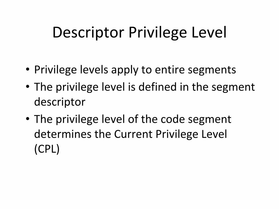
Descriptor Privilege Level
• Privilege levels apply to entire segments• The privilege level is defined in the segment
descriptor• The privilege level of the code segment
determines the Current Privilege Level (CPL)

Type 1: Privilege Checking
• Privileged Instructions1. Segmentation and Protection Based (HLT, CLTS,
LGDT, LIDT, LLDT, LTR, moving data to Control, Debug and Test registers)
2. Interrupt flag based (CLI, STI, IN, INS, OUT, OUTS)3. Peripheral IO based
● First two types of privileged instructions can be executed only when CPL = 0, that is, these instructions can be in code segment with DPL = 0.

I/O instructions
• The I/O based privileged instructions are executed only if CPL <= IOPL in EFLAGS register.
• To add to the security the POPF/POPFD instructions which load values into the EFLAGS shall not touch the IOPL bit or IF bit if CPL > 0.

Type 2: Privilege Checking
• Reference data other than its own• Load a selector into a DS, ES, FS and GS iff max(RPL,CPL)
<= DPL– RPL may weaken your privilege level– Decreasing RPL will not strengthen your privilege level
– Why?– Why to decrease RPL – will discuss later
• Load a descriptor into a stack iff DPL = CPL• All these are in addition to the rules for loading segment
selector, that were stated in Slides 87 and 88.

Type 3: Privilege Checking
• Transfer control to code other than its own. Essentially load a new selector into CS register
• jmp across code segments with same DPL– jmp <selector>:<offset of instruction from
start of the new segment>– call <selector>:<offset of instruction from start
of the new segment>

Changing Privilege levels
• Control transfer from a code of some PL to another code with some other different PL.
• Using conforming code segments or a special segment descriptor called call gates.
• Conforming code segments confirms with the privilege level of the calling code. So if a control transfer happens from segment S to a confirming segment T, the privilege of T would be the privilege of S.
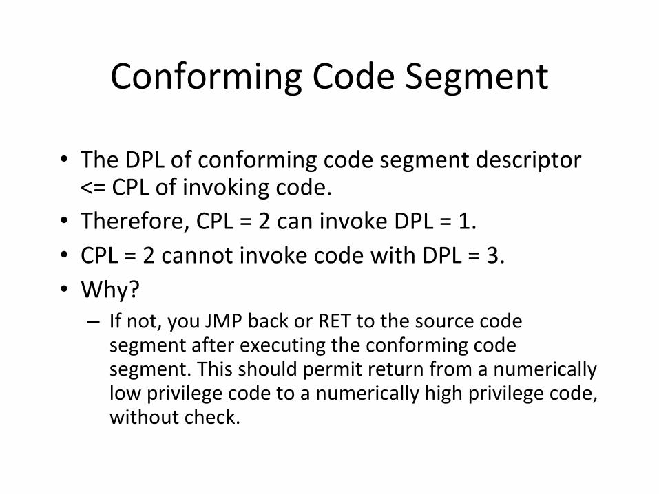
Conforming Code Segment
• The DPL of conforming code segment descriptor <= CPL of invoking code.
• Therefore, CPL = 2 can invoke DPL = 1.• CPL = 2 cannot invoke code with DPL = 3.• Why?
– If not, you JMP back or RET to the source code segment after executing the conforming code segment. This should permit return from a numerically low privilege code to a numerically high privilege code, without check.

CALL GATE descriptor
• Is defined by a system descriptor (S=0) in GDT which is used by the JMP or CALL.
Destination Offset
15-0
Destination Selector (16 bits)
WC00001100
P, DPLDestination offset
31-16
The 64-bit descriptor in GDT
•Not only the selector for the target code segment, but also the offset in the code segment from which you should start executing is specified. The source code segment can only use it like a black-box

Calling Higher privileged code
SEGCALL OFFSETSEGCALL OFFSET
Correct Incorrect
Gate – Sel + offset
Code Desc
Code Seg Code Seg
Code Desc

Call Gates
• Are defined like segment descriptors• Occupy a slot in the descriptor tables• Provide the only means to alter the current
privilege level• Define entry points to other privilege levels• Must be invoked using a CALL Instruction
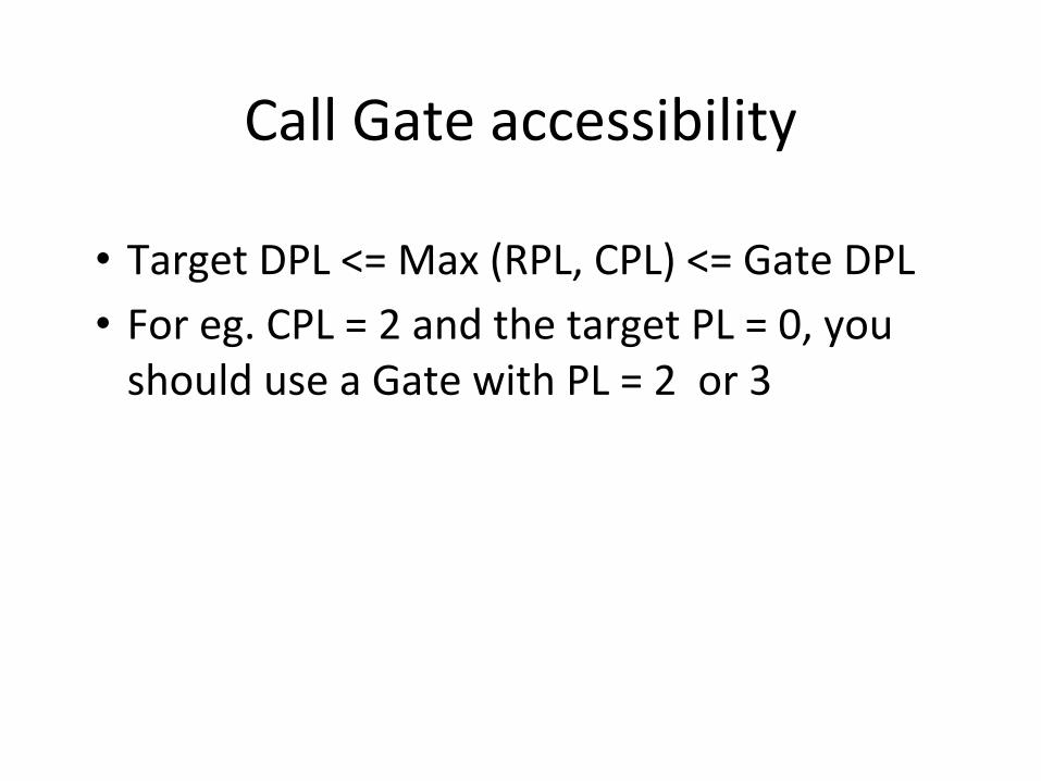
Call Gate accessibility
• Target DPL <= Max (RPL, CPL) <= Gate DPL• For eg. CPL = 2 and the target PL = 0, you
should use a Gate with PL = 2 or 3

Privilege levels and Stacks
• The stack PL = CPL always• When changing the CPL, the processor
automatically changes the stack!!!• How – using the Task State Segment (TSS)• The base of the TSS is stored in a Task register
(TR) which is updated by the privileged instruction LTR
• The TSS associates a stack for each code for each of the privilege levels 0, 1 and 2

Privileged Instructions
• HLT -- HaltOperation Enter Halt state;
Description HALT stops instruction execution and places the 80386 in a
HALT state. An enabled interrupt, NMI, or a reset will resume execution. If an interrupt (including NMI) is used to resume execution after HLT, the saved CS:IP (or CS:EIP) value points to the instruction following HLT.
Flags Affected None
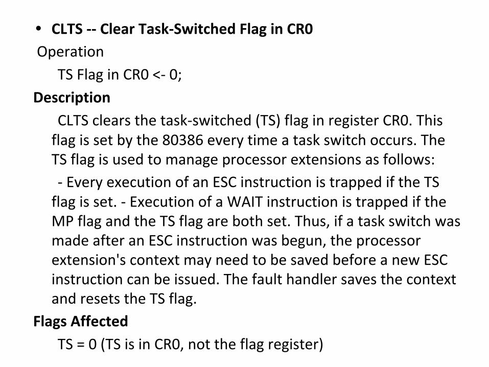
• CLTS -- Clear Task-Switched Flag in CR0 Operation
TS Flag in CR0 <- 0; Description
CLTS clears the task-switched (TS) flag in register CR0. This flag is set by the 80386 every time a task switch occurs. The TS flag is used to manage processor extensions as follows: - Every execution of an ESC instruction is trapped if the TS
flag is set. - Execution of a WAIT instruction is trapped if the MP flag and the TS flag are both set. Thus, if a task switch was made after an ESC instruction was begun, the processor extension's context may need to be saved before a new ESC instruction can be issued. The fault handler saves the context and resets the TS flag.
Flags Affected TS = 0 (TS is in CR0, not the flag register)
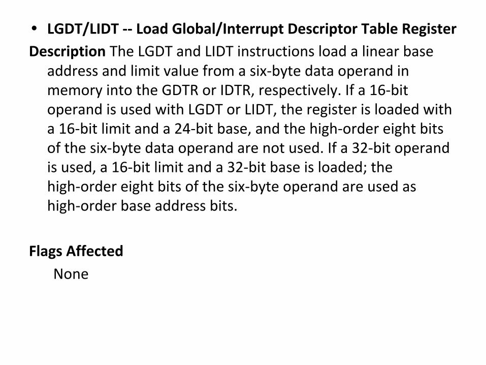
• LGDT/LIDT -- Load Global/Interrupt Descriptor Table RegisterDescription The LGDT and LIDT instructions load a linear base
address and limit value from a six-byte data operand in memory into the GDTR or IDTR, respectively. If a 16-bit operand is used with LGDT or LIDT, the register is loaded with a 16-bit limit and a 24-bit base, and the high-order eight bits of the six-byte data operand are not used. If a 32-bit operand is used, a 16-bit limit and a 32-bit base is loaded; the high-order eight bits of the six-byte operand are used as high-order base address bits.
Flags Affected None
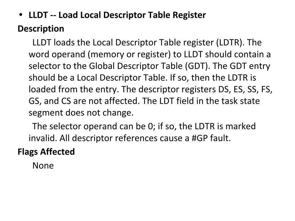
• LLDT -- Load Local Descriptor Table RegisterDescription LLDT loads the Local Descriptor Table register (LDTR). The
word operand (memory or register) to LLDT should contain a selector to the Global Descriptor Table (GDT). The GDT entry should be a Local Descriptor Table. If so, then the LDTR is loaded from the entry. The descriptor registers DS, ES, SS, FS, GS, and CS are not affected. The LDT field in the task state segment does not change. The selector operand can be 0; if so, the LDTR is marked
invalid. All descriptor references cause a #GP fault. Flags Affected
None

• LTR -- Load Task RegisterDescription
LTR loads the task register from the source register or memory location specified by the operand. The loaded task state segment is marked busy. A task switch does not occur. LTR is used only in operating system
software; it is not used in application programs.
Flags Affected None

• LMSW -- Load Machine Status Word Description
LMSW loads the machine status word (part of CR0) from the source operand. This instruction can be used to switch to Protected Mode; if so, it must be followed by an intra-segment jump to flush the instruction queue. LMSW will not switch back to Real Address Mode.
Flags Affected None

• MOV CRn , REG / MOV REG , CRn Description
The above forms of MOV store or load Control registers CR0, CR2, and CR3 in or from a general purpose register 32-bit operands are always used with these
instructions, regardless of the operand-size attribute
Flags Affected OF, SF, ZF, AF, PF, and CF are undefined
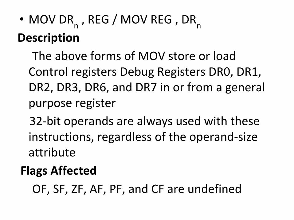
• MOV DRn , REG / MOV REG , DRn Description
The above forms of MOV store or load Control registers Debug Registers DR0, DR1, DR2, DR3, DR6, and DR7 in or from a general purpose register
32-bit operands are always used with these instructions, regardless of the operand-size attribute
Flags Affected OF, SF, ZF, AF, PF, and CF are undefined

• MOV TRn , REG / MOV REG , TRn The above forms of MOV store or load
Control registers Test Registers TR6 and TR7 in or from a general purpose register
32-bit operands are always used with these instructions, regardless of the operand-size attribute
Flags Affected OF, SF, ZF, AF, PF, and CF are undefined

IOPL Sensitive Instructions• IF CPL <= IOPL then only these instructions will be
executed• The instructions are :
CLI -- Clear Interrupt FlagSTI -- Set Interrupt FlagIN -- Input from PortINS/INSB/INSW/INSD -- Input from Port to StringOUT -- Output to PortOUTS/OUTSB/OUTSW/OUTSD -- Output String to Port

• CLI -- Clear Interrupt FlagDescription
CLI clears the interrupt flag if the current privilege level is at least as privileged as IOPL. No other flags are affected. External interrupts are not recognized at the end of the CLI instruction or from that point on until the interrupt flag is set.
Flags Affected IF = 0
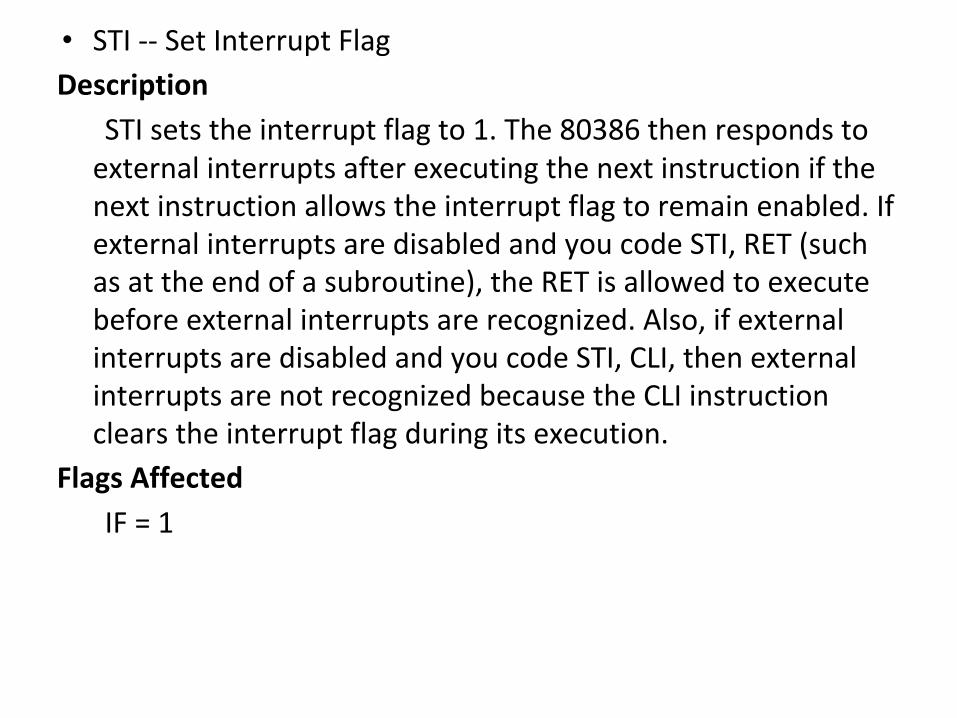
• STI -- Set Interrupt FlagDescription
STI sets the interrupt flag to 1. The 80386 then responds to external interrupts after executing the next instruction if the next instruction allows the interrupt flag to remain enabled. If external interrupts are disabled and you code STI, RET (such as at the end of a subroutine), the RET is allowed to execute before external interrupts are recognized. Also, if external interrupts are disabled and you code STI, CLI, then external interrupts are not recognized because the CLI instruction clears the interrupt flag during its execution.
Flags Affected IF = 1

• IN -- Input from PortDescription
IN transfers a data byte or data word from the port numbered by the second operand into the register (AL, AX, or EAX) specified by the first operand. Access any port from 0 to 65535 by placing the port number in the DX register and using an IN instruction with DX as the second parameter. These I/O instructions can be shortened by using an 8-bit port I/O in the instruction. The upper eight bits of the port address will be 0 when 8-bit port I/O is used.
Flags Affected None

• INS/INSB/INSW/INSD -- Input from Port to StringDescription
INS transfers data from the input port numbered by the DX register to the memory byte or word at ES:dest-index. The memory operand must be addressable from ES; no segment override is possible. The destination register is DI if the address-size attribute of the instruction is 16 bits, or EDI if the address-size attribute is 32 bits.
INS does not allow the specification of the port number as an immediate value. The port must be addressed through the DX register value. Load the correct value into DX before executing the INS instruction.
The destination address is determined by the contents of the destination index register. Load the correct index into the destination index register before executing INS.
After the transfer is made, DI or EDI advances automatically. If the direction flag is 0 (CLD was executed), DI or EDI increments; if the direction flag is 1 (STD was executed), DI or EDI decrements. DI increments or decrements by 1 if a byte is input, by 2 if a word is input, or by 4 if a double word is input.
INSB, INSW and INSD are synonyms of the byte, word, and double word INS instructions. INS can be preceded by the REP prefix for block input of CX bytes or words. Refer to the REP instruction for details of this operation.
Flags Affected None

• OUT -- Output to PortDescription
OUT transfers a data byte or data word from the register (AL, AX, or EAX) given as the second operand to the output port numbered by the first operand. Output to any port from 0 to 65535 is performed by placing the port number in the DX register and then using an OUT instruction with DX as the first operand. If the instruction contains an eight-bit port ID, that value is zero-extended to 16 bits.
Flags Affected None
• OUTS/OUTSB/OUTSW/OUTSD -- Output String to PortDescription
OUTS transfers data from the memory byte, word, or double word at the source-index register to the output port addressed by the DX register. If the address-size attribute for this instruction is 16 bits, SI is used for the source-index register; otherwise, the address-size attribute is 32 bits, and ESI is used for the source-index register.
OUTS does not allow specification of the port number as an immediate value. The port must be addressed through the DX register value. Load the correct value into DX before executing the OUTS instruction.
The address of the source data is determined by the contents of source-index register. Load the correct index value into SI or ESI before executing the OUTS instruction.
After the transfer, source-index register is advanced automatically. If the direction flag is 0 (CLD was executed), the source-index register is incremented; if the direction flag is 1 (STD was executed), it is decremented. The amount of the increment or decrement is 1 if a byte is output, 2 if a word is output, or 4 if a double word is output.
OUTSB, OUTSW, and OUTSD are synonyms for the byte, word, and double word OUTS instructions. OUTS can be preceded by the REP prefix for block output of CX bytes or words. Refer to the REP instruction for details on this operation.
Flags Affected None

Thanks for being patient!


![Cognitive effort in metaphor translation - [email protected]](https://img.pdfslide.us/doc/110x75/620a93a56508dd10d5524e08/cognitive-effort-in-metaphor-translation-emailprotected.jpg)