Embed Size (px)
Citation preview
Prosthetic Choices for People withLeg and Arm Amputations
Robert S. Kistenberg, MPH, L/CP
KEYWORDS
� Prosthetics � Amputation � Artificial limbs � Amputees
KEY POINTS
� Provision of a prosthesis is only a component of prosthetic rehabilitation. It takes a coor-dinated team to optimize outcomes and functional independence.
� The most sophisticated components are not the most appropriate for everyone. All op-tions must be weighed with consideration of the person who will be wearing the pros-thesis, their environment, and realistic goals.
� Suspension is integral in most socket designs and must be optimized in order to preventrubbing, slipping and fitting complications.
INTRODUCTION
Prosthesis (noun): a single artificial limb
Prostheses (plural noun): more than one artificial limb
Prosthetic (adjective): of or relating to artificial limbs (ie, prosthetic leg)
Prosthetics (noun): the profession or field of study related to artificial limbs
The explosion of options that modern technology has afforded individuals who sustainamputations or who are born with congenital limb deficiencies can be overwhelmingfor health care practitioners and people who rely on prosthetic technology alike. Pow-ered, microprocessor-equipped components offer enhanced control and sophisticat-ion. Material and technology advances, improved socket designs, surgicaltechniques, and prosthetic rehabilitation have empowered prosthetists (and the healthcare team) with the ability to truly deliver the most advanced prostheses ever invented.This trend will continue in perpetuity.Yet the most sophisticated device is not the most appropriate for everyone. The
excitement provided through the media often gives people unrealistic expectations
Georgia Institute of Technology, School of Applied Physiology, 555 14th Street, Atlanta, GA30318, USAE-mail address: [email protected]
Phys Med Rehabil Clin N Am 25 (2014) 93–115http://dx.doi.org/10.1016/j.pmr.2013.10.001 pmr.theclinics.com1047-9651/14/$ – see front matter � 2014 Elsevier Inc. All rights reserved.
Kistenberg94
of the capacities that can be attained through the utilization of the latest and greatest.And for people who are not candidates for the best currently available prostheses, forwhat type of prostheses are they candidates? Strong scientific evidence dictatingchoices regarding specific components, suspension systems, and/or socket designsdoes not (yet) exist. How do you choose?The aim of this article is to present the options that are available for people who rely
on artificial limbs to enhance their quality of life for mobility and independence. Com-ponents by name, manufacturer, or coding category have been bypassed in lieu of afocus on features and considerations that must be made in order to make informeddecisions; however, specific examples are included. Sockets, liners, and suspensionsystems for all levels of amputation or limb deficiency are presented first, followed bysections about feet, ankles, knees, and hip joints (for lower limb prostheses) and thensections on terminal devices, wrists, elbows, and shoulder joints (for upper limb pros-theses). Although funding sources play a significant and often primary role in decisionsregarding access to prosthetic rehabilitation services, the impact of funding limitationson one’s choices related to prosthetic rehabilitation services are not considerations ofthis article.
SOCKETS, LINERS, AND SUSPENSION SYSTEMS
If the interface between the wearer and the device is intolerable, nothing else matters.
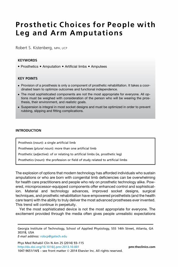
Contemporary socket designs include lightweight carbon outer frames wrappedthoughtfully around advanced thermoplastic, anatomically optimized shells. Socketliner technology has evolved from wool socks and polyethylene foam to liners madefrom urethane, silicones, or thermoplastic elastomers. Grouped generically as gelliners, they are the most commonly used prosthetic interface in North America. Allgel-type liners must be rolled onto a residual limb with careful attention to avoid air be-tween the skin and the liner; hence, dexterity is required for independent donning.Liners also require daily washing, require regular replacement (6–12 months), maybe hot, and perceived as bulky. Different types of liners are integral to different sus-pension systems.Cushion liners consist of different thicknesses of gel with or without a fabric covering
and are rarely sufficient to provide suspension alone (Fig. 1). In transtibial applications,they are combined with a knee sleeve, which seals the residual limb/socket chamber,and an expulsion valve creating a suction socket. The chamber is created between theinner surface of the prosthetic socket and the outer surface of the liner, not betweenthe liner and the skin. Negative pressure (subatmospheric) is created when the resid-ual limb is pressed into the socket on loading and subsequently extracted duringunloading. Variations of this sealed suction system have been used on transfemoral,hip disarticulation, and upper limb prostheses.Elevated vacuum (also known as vacuum assisted) suspension takes the same sys-
tem described earlier; however, the negative pressure in the chamber is increased bythe addition of an electric or mechanical vacuum pump. Elevated vacuum suspensionreduces residual limb pistoning,1 reduces residual limb volume loss,1–4 and hasdemonstrated value in residual limb wound healing.5 In addition to added weightand the need for daily charging (for electric pump systems), the knee sleeve mayrestrict the knee range of motion in transtibial elevated vacuum wearers. Liners for
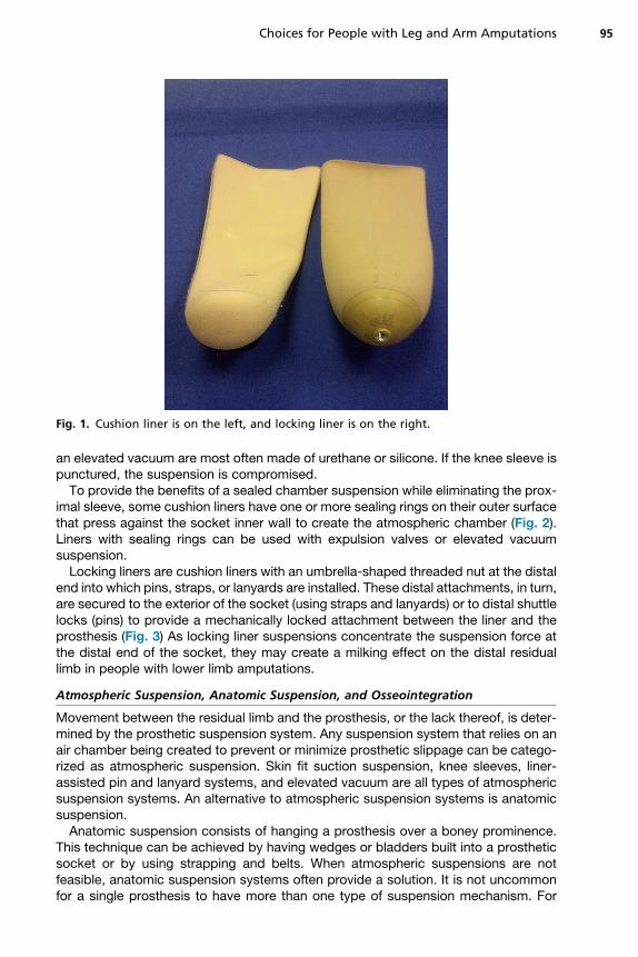
Fig. 1. Cushion liner is on the left, and locking liner is on the right.
Choices for People with Leg and Arm Amputations 95
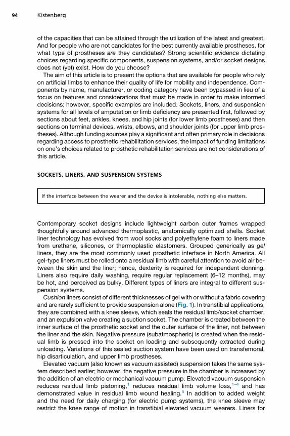
an elevated vacuum are most often made of urethane or silicone. If the knee sleeve ispunctured, the suspension is compromised.To provide the benefits of a sealed chamber suspension while eliminating the prox-
imal sleeve, some cushion liners have one or more sealing rings on their outer surfacethat press against the socket inner wall to create the atmospheric chamber (Fig. 2).Liners with sealing rings can be used with expulsion valves or elevated vacuumsuspension.Locking liners are cushion liners with an umbrella-shaped threaded nut at the distal
end into which pins, straps, or lanyards are installed. These distal attachments, in turn,are secured to the exterior of the socket (using straps and lanyards) or to distal shuttlelocks (pins) to provide a mechanically locked attachment between the liner and theprosthesis (Fig. 3) As locking liner suspensions concentrate the suspension force atthe distal end of the socket, they may create a milking effect on the distal residuallimb in people with lower limb amputations.
Atmospheric Suspension, Anatomic Suspension, and Osseointegration
Movement between the residual limb and the prosthesis, or the lack thereof, is deter-mined by the prosthetic suspension system. Any suspension system that relies on anair chamber being created to prevent or minimize prosthetic slippage can be catego-rized as atmospheric suspension. Skin fit suction suspension, knee sleeves, liner-assisted pin and lanyard systems, and elevated vacuum are all types of atmosphericsuspension systems. An alternative to atmospheric suspension systems is anatomicsuspension.Anatomic suspension consists of hanging a prosthesis over a boney prominence.
This technique can be achieved by having wedges or bladders built into a prostheticsocket or by using strapping and belts. When atmospheric suspensions are notfeasible, anatomic suspension systems often provide a solution. It is not uncommonfor a single prosthesis to have more than one type of suspension mechanism. For
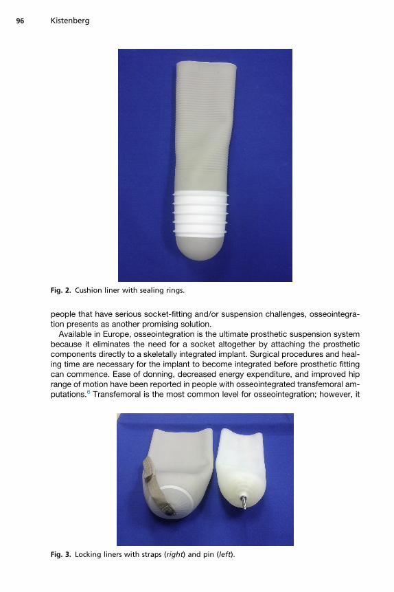
Fig. 2. Cushion liner with sealing rings.
Kistenberg96
people that have serious socket-fitting and/or suspension challenges, osseointegra-tion presents as another promising solution.Available in Europe, osseointegration is the ultimate prosthetic suspension system
because it eliminates the need for a socket altogether by attaching the prostheticcomponents directly to a skeletally integrated implant. Surgical procedures and heal-ing time are necessary for the implant to become integrated before prosthetic fittingcan commence. Ease of donning, decreased energy expenditure, and improved hiprange of motion have been reported in people with osseointegrated transfemoral am-putations.6 Transfemoral is the most common level for osseointegration; however, it
Fig. 3. Locking liners with straps (right) and pin (left).
Choices for People with Leg and Arm Amputations 97
has also been successfully applied to transtibial, digital, transradial, and transhumerallevel amputations. The incidence of infection is one of the reasons osseointegrationhas not received approval by the Food and Drug Administration in the United States;however, human trials are undergoing.7
LOWER LIMB PROSTHETICSProsthetic Foot and Ankle Mechanisms
Prosthetic feet are often grouped according to historical categories because thesecategories evolved to become descriptors for reimbursement codes. Examples ofcommon foot categories include solid ankle cushion heel (SACH) feet, flexible keelfeet, dynamic response feet, and single axis and multi axis feet; however, it hasbeen acknowledged that the codes (categories) into which feet have been assignedlack a standardized methodology to test mechanical abilities.8 Scientific evidence torecommend specific prosthetic foot-ankle mechanisms is lacking.9 As early as1975, Daher10 demonstrated that even feet within the same category do not performthe same in mechanical testing. Rather than using historical categories, the followingsections focus on primary prosthetic foot selection considerations, the prosthetic footkeel, the prosthetic foot heel, as well as prosthetic foot aesthetics and shoes.
Primary Foot Selection Considerations
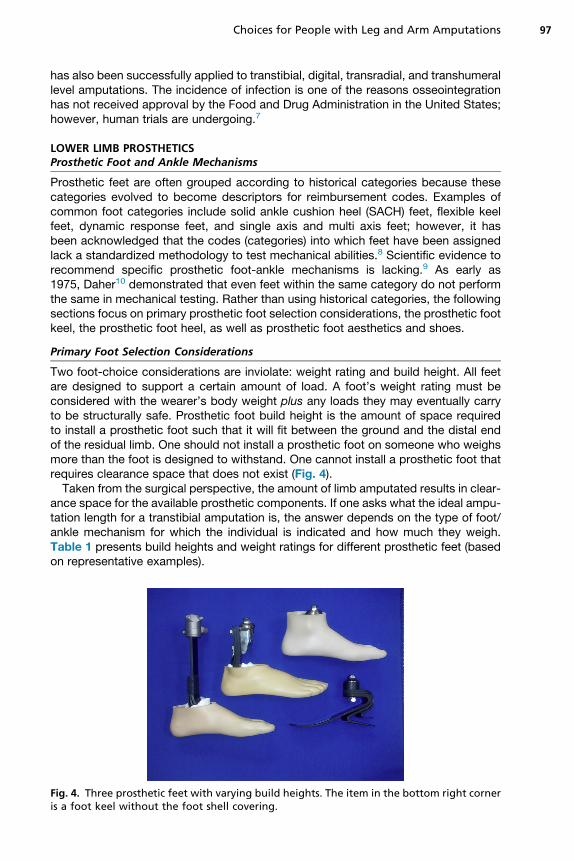
Two foot-choice considerations are inviolate: weight rating and build height. All feetare designed to support a certain amount of load. A foot’s weight rating must beconsidered with the wearer’s body weight plus any loads they may eventually carryto be structurally safe. Prosthetic foot build height is the amount of space requiredto install a prosthetic foot such that it will fit between the ground and the distal endof the residual limb. One should not install a prosthetic foot on someone who weighsmore than the foot is designed to withstand. One cannot install a prosthetic foot thatrequires clearance space that does not exist (Fig. 4).Taken from the surgical perspective, the amount of limb amputated results in clear-
ance space for the available prosthetic components. If one asks what the ideal ampu-tation length for a transtibial amputation is, the answer depends on the type of foot/ankle mechanism for which the individual is indicated and how much they weigh.Table 1 presents build heights and weight ratings for different prosthetic feet (basedon representative examples).
Fig. 4. Three prosthetic feet with varying build heights. The item in the bottom right corneris a foot keel without the foot shell covering.
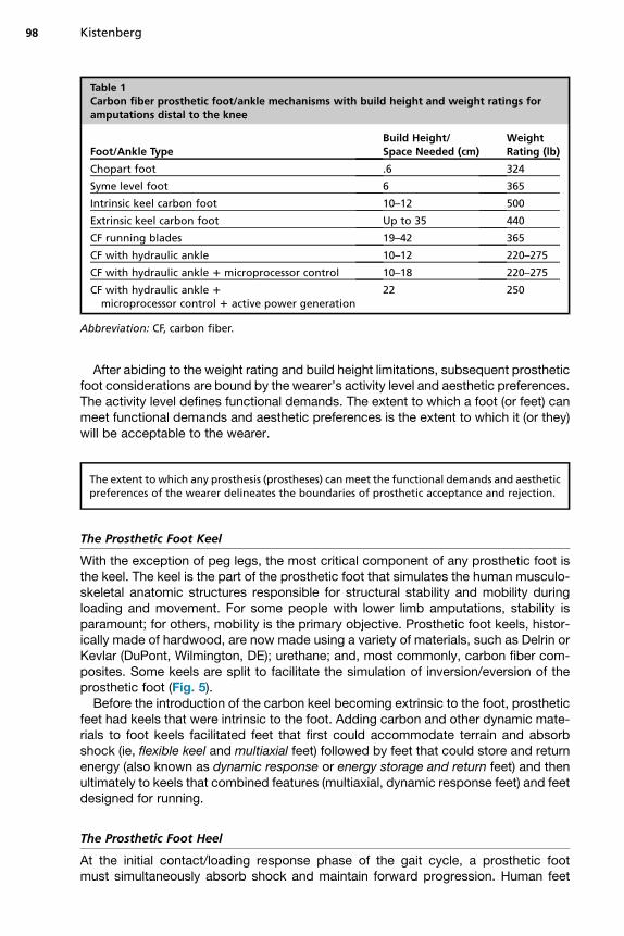
Table 1Carbon fiber prosthetic foot/ankle mechanisms with build height and weight ratings foramputations distal to the knee
Foot/Ankle TypeBuild Height/Space Needed (cm)
WeightRating (lb)
Chopart foot .6 324
Syme level foot 6 365
Intrinsic keel carbon foot 10–12 500
Extrinsic keel carbon foot Up to 35 440
CF running blades 19–42 365
CF with hydraulic ankle 10–12 220–275
CF with hydraulic ankle 1 microprocessor control 10–18 220–275
CF with hydraulic ankle 1
microprocessor control 1 active power generation22 250
Abbreviation: CF, carbon fiber.
Kistenberg98
After abiding to the weight rating and build height limitations, subsequent prostheticfoot considerations are bound by the wearer’s activity level and aesthetic preferences.The activity level defines functional demands. The extent to which a foot (or feet) canmeet functional demands and aesthetic preferences is the extent to which it (or they)will be acceptable to the wearer.
The extent to which any prosthesis (prostheses) can meet the functional demands and aestheticpreferences of the wearer delineates the boundaries of prosthetic acceptance and rejection.
The Prosthetic Foot Keel
With the exception of peg legs, the most critical component of any prosthetic foot isthe keel. The keel is the part of the prosthetic foot that simulates the human musculo-skeletal anatomic structures responsible for structural stability and mobility duringloading and movement. For some people with lower limb amputations, stability isparamount; for others, mobility is the primary objective. Prosthetic foot keels, histor-ically made of hardwood, are now made using a variety of materials, such as Delrin orKevlar (DuPont, Wilmington, DE); urethane; and, most commonly, carbon fiber com-posites. Some keels are split to facilitate the simulation of inversion/eversion of theprosthetic foot (Fig. 5).Before the introduction of the carbon keel becoming extrinsic to the foot, prosthetic
feet had keels that were intrinsic to the foot. Adding carbon and other dynamic mate-rials to foot keels facilitated feet that first could accommodate terrain and absorbshock (ie, flexible keel and multiaxial feet) followed by feet that could store and returnenergy (also known as dynamic response or energy storage and return feet) and thenultimately to keels that combined features (multiaxial, dynamic response feet) and feetdesigned for running.
The Prosthetic Foot Heel
At the initial contact/loading response phase of the gait cycle, a prosthetic footmust simultaneously absorb shock and maintain forward progression. Human feet
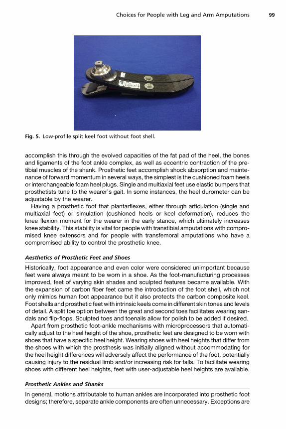
Fig. 5. Low-profile split keel foot without foot shell.
Choices for People with Leg and Arm Amputations 99
accomplish this through the evolved capacities of the fat pad of the heel, the bonesand ligaments of the foot ankle complex, as well as eccentric contraction of the pre-tibial muscles of the shank. Prosthetic feet accomplish shock absorption and mainte-nance of forward momentum in several ways, the simplest is the cushioned foam heelsor interchangeable foam heel plugs. Single andmultiaxial feet use elastic bumpers thatprosthetists tune to the wearer’s gait. In some instances, the heel durometer can beadjustable by the wearer.Having a prosthetic foot that plantarflexes, either through articulation (single and
multiaxial feet) or simulation (cushioned heels or keel deformation), reduces theknee flexion moment for the wearer in the early stance, which ultimately increasesknee stability. This stability is vital for people with transtibial amputations with compro-mised knee extensors and for people with transfemoral amputations who have acompromised ability to control the prosthetic knee.
Aesthetics of Prosthetic Feet and Shoes
Historically, foot appearance and even color were considered unimportant becausefeet were always meant to be worn in a shoe. As the foot-manufacturing processesimproved, feet of varying skin shades and sculpted features became available. Withthe expansion of carbon fiber feet came the introduction of the foot shell, which notonly mimics human foot appearance but it also protects the carbon composite keel.Foot shells andprosthetic feetwith intrinsic keels come in different skin tones and levelsof detail. A split toe option between the great and second toes facilitates wearing san-dals and flip-flops. Sculpted toes and toenails allow for polish to be added if desired.Apart from prosthetic foot-ankle mechanisms with microprocessors that automati-
cally adjust to the heel height of the shoe, prosthetic feet are designed to be worn withshoes that have a specific heel height. Wearing shoes with heel heights that differ fromthe shoes with which the prosthesis was initially aligned without accommodating forthe heel height differences will adversely affect the performance of the foot, potentiallycausing injury to the residual limb and/or increasing risk for falls. To facilitate wearingshoes with different heel heights, feet with user-adjustable heel heights are available.
Prosthetic Ankles and Shanks
In general, motions attributable to human ankles are incorporated into prosthetic footdesigns; therefore, separate ankle components are often unnecessary. Exceptions are
Kistenberg100
when vertical loading and/or torsional demands go beyond the capabilities of theprosthetic foot (for example, with golf or basketball). To meet these demands, verticalshock pylons and torque absorbers are available.Although the application of hydraulics to dampen ankle motion is not new,11 several
manufacturers have recently reintroduced hydraulically controlled ankle mechanismsas a means to passively adapt to different terrains. The addition of microprocessors toprosthetic foot/ankle mechanisms to control ankle motion allows prosthetic feet tobehave similarly to human feet. For example, the prosthetic foot/ankle mechanismcan dorsiflex during the swing phase to facilitate toe clearance and automaticallyadapt to different heel heights between shoes. The recent introduction of an activelypowered prosthetic foot/ankle mechanism (BiOM Ankle System, iWalk Inc, Bedford,MA) now allows for gait performance of people with lower limb amputations to notbe statistically significantly different from that of people without amputations acrossdifferent gait velocities.12 The downside to the addition of these sophisticated compo-nents is the added weight, bulk, maintenance, and financial cost.
Prosthetic Knees
Prosthetic knees and the ability to control them have a drastic effect on the quality oflife for individuals with knee disarticulations or more proximal lower limb amputationlevels. People with amputations who lack the ability to maintain the prosthetic kneein extension during the stance phase or insufficient flexion during the swing phasefor toe clearance are at risk for falls. Active community ambulators who vary theircadence and terrain require a knee that can accommodate ever-changing speedsand conditions. Before the advent of microprocessor control of prosthetic knees,wearers would often comment that they had to think about every step in order to pre-vent inadvertent knee collapse and falls. When compared with walking with non–microprocessor-controlled knees, people report that walking requires less attentionwhen wearing a microprocessor-controlled knee (MPKs).13
The impact that microprocessor control has had on prosthetic knees is so significantthat knees are now categorized as either exclusive mechanical control (non-MPKs) orMPKs.14 Byway of introduction to knee designs and features, the following sections onknee axis configurations, fluid dampening versus constant friction, and 4 additionalknee features are specific to non-MPKs. The subsequent section addresses MPKs.
Knee Axis Configurations
Historically, prosthetic knees were categorized according to their axis design (singleaxis vs polycentric knees) because different axis designs were indicated based onthe wearer’s residual limb length, functional demands, and their ability to control theknee. For non-MPKs, these indications still apply. As the name implies, single-axisknees rotate about one axis and are mechanically simpler and lighter than their poly-centric counterparts.Polycentric knees (also known as 4-bar knees, although some designs have greater
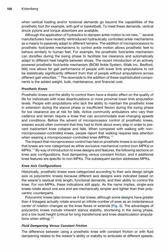
than 4 linkages) actually rotate around an infinite number of axes as an instantaneouscenter of rotation changes as the knee flexes or extends (Fig. 6). The advantages ofpolycentric knees include inherent stance stability, shortening in the swing phase,and a low build height (critical for long transfemoral and knee disarticulation amputa-tions when sitting).15
Fluid Dampening Versus Constant Friction
The difference between using a prosthetic knee with constant friction or with fluiddampening relates to the wearer’s ability or inability to ambulate at different speeds.
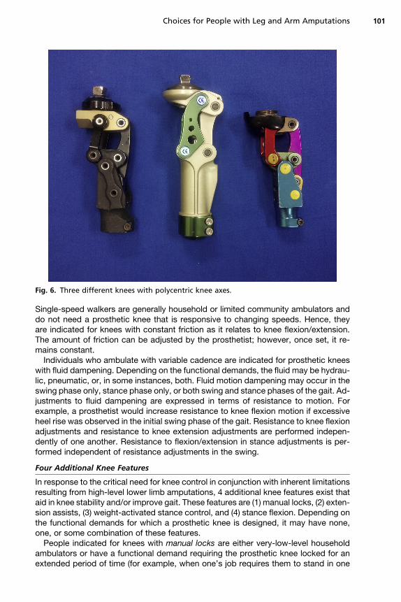
Fig. 6. Three different knees with polycentric knee axes.
Choices for People with Leg and Arm Amputations 101
Single-speed walkers are generally household or limited community ambulators anddo not need a prosthetic knee that is responsive to changing speeds. Hence, theyare indicated for knees with constant friction as it relates to knee flexion/extension.The amount of friction can be adjusted by the prosthetist; however, once set, it re-mains constant.Individuals who ambulate with variable cadence are indicated for prosthetic knees
with fluid dampening. Depending on the functional demands, the fluid may be hydrau-lic, pneumatic, or, in some instances, both. Fluid motion dampening may occur in theswing phase only, stance phase only, or both swing and stance phases of the gait. Ad-justments to fluid dampening are expressed in terms of resistance to motion. Forexample, a prosthetist would increase resistance to knee flexion motion if excessiveheel rise was observed in the initial swing phase of the gait. Resistance to knee flexionadjustments and resistance to knee extension adjustments are performed indepen-dently of one another. Resistance to flexion/extension in stance adjustments is per-formed independent of resistance adjustments in the swing.
Four Additional Knee Features
In response to the critical need for knee control in conjunction with inherent limitationsresulting from high-level lower limb amputations, 4 additional knee features exist thataid in knee stability and/or improve gait. These features are (1) manual locks, (2) exten-sion assists, (3) weight-activated stance control, and (4) stance flexion. Depending onthe functional demands for which a prosthetic knee is designed, it may have none,one, or some combination of these features.People indicated for knees with manual locks are either very-low-level household
ambulators or have a functional demand requiring the prosthetic knee locked for anextended period of time (for example, when one’s job requires them to stand in one
Kistenberg102
place). The lock is disengaged for sitting; however, this requires hand dexterity, whichmay be a challenge for those who require an assistive device, such as a walker, forstability.Extension assists are elastic components that facilitate the prosthetic knee to attain
full extension once it has flexed during the swing phase. People with general weak-ness or with weak hip flexors are indicated for knees that have extension assists.Extension assists are adjustable because excessive assistance can result in the pros-thetic knee snapping into full extension with an audible terminal impact. Prosthetistsadjust extension-assist components in harmony with constant friction or fluid damp-ening adjustments because these aspects of prosthetic knee function are interrelated.Weight-activated stance control is a feature that uses a braking mechanism to lock
the knee if weight is applied while the knee is not in full extension. Individuals who arelow-level walkers or identified with a fall risk are indicated for a prosthetic knee withweight-activated stance control. The amount of weight required to activate the brakeis adjustable, and different knees offer different ranges of knee flexion within which theweight-activated stance control will engage. To induce knee flexion for a knee withweight-activated stance control, it needs to be fully unweighted. This may result inawkward transitions from the preswing to the initial swing phase of the gait. It alsomay present challenges for initiating flexion when sitting. Although weight-activatedstance control is a safety feature of prosthetic knees, exercise caution when referringto this type of knee as a safety knee because this is misleading and may open prac-titioners up to liability.The fourth feature for prosthetic knees, stance flexion, differs from the first 3 be-
cause it is designed to enable the gait of people with amputations to resemble a non-amputated gait by allowing for some amount of knee flexion at the initial contact/loading response phases of walking. Although initially posited by Saunders and col-leagues16 to play a role in reducing vertical trunk displacement, stance-phase kneeflexion was determined by Gard and Childress17 to play a role not in vertical displace-ment but in shock absorption. Attenuating shock for people with transfemoral ampu-tations is vital because chronic low-back pain has been documented in people withlower extremity amputations.18,19 Hence, the stance flexion feature in prosthetic kneesis appropriate for individuals who are variable-cadence community ambulators and/orat risk for back pain. It should be noted that the transition from a prosthetic kneewithout stance flexion to a knee with stance flexion may be challenging because thesensation of knee bending at initial contact/loading response is associated withknee buckling and falling by people accustomed to knees without stance flexion.Every prosthetic knee, either non-MPK or MPK, will have either a single axis or poly-
centric design; every prosthetic knee requires somemethod to control itsmotion. The 4additional features described earlier for non-MPKsmay ormay not be present depend-ing on the population for which a particular knee was designed. The introduction of mi-croprocessors to prosthetic knees has allowed prosthetic designs to incorporate theaforementioned features either through mechanical means, microprocessor control,or a combination of both.
Microprocessor Control of Prosthetic Knees
The first prosthetic knee to incorporatemicroprocessor control of the swing phase wasthe Blatchford Intelligent Prosthesis (IP, Chas A Blatchford & Sons Ltd, Hampshire,United Kingdom) in the early 1990s.14 The C-Leg (Ottobock, Duderstadt, Germany),introduced in the late 1990s, was the first prosthetic knee with microprocessor controlof both the swing and stance phase. Although intelligent swing-phase control mayoptimize the swing, microprocessor stance-phase control is the feature that launched
Choices for People with Leg and Arm Amputations 103
the MPK revolution. With stance control, the prosthetic knee could respond automat-ically to varying conditions of stair and ramp ascent and descent as well as uneven ter-rains, conditions exceptionally challenging for most people with high-level lower limbamputations.The introduction of the Power Knee (Ossur, Reykjavik, Iceland) in 2006 brought
microprocessor control of the prosthetic knee to the next level by not only controllingthe knee’s motion but also by actively adding power to the knee, reportedly facilitatingthe ability for people with transfemoral amputations to walk up stairs step over step.Comparing the Power Knee with the C-Leg in stair and ramp ascent and descentamong 5 young and motivated people with unilateral transfemoral amputations,Wolf and colleagues20 concluded that the Power Knee did significantly reduce thepower generated by the nondisabled knee during stair ascent as designed. Wolfand colleagues21 also compared the 2 knees for sit-to-stand and step-up tasks andfound no significant differences between either of the affected limbs or the intactlimb when comparing devices. The latest innovation with regard to lower limb pros-thetics is the incorporation of a MPK and foot working in harmony as is seen in theSymbionic leg (Ossur, Reykjavik, Iceland).Although the advantages of microprocessor control have been well publicized,
before choosing a MCK one must also consider the need for regular charging, mois-ture restrictions, added weight, and the short- and long-term costs.
Transverse Rotators: an Important Component for People with TransfemoralAmputations
For individuals who have transfemoral amputations and who have enough clearancebetween the end of their residual limb and their prosthetic knee joint, the addition ofa transverse rotator can make the difference between acceptance and rejection of aprosthesis. With the push of a button, the section of the prosthesis distal to the socketcan freely rotate in the transverse plane. This function enables the wearer to changetheir shoes without forward flexing at the waist or having to remove their prosthesis.Transverse rotators can facilitate getting into a vehicle and comfortable sitting in avehicle. For individuals who sit on the floor, they allow one to sit with their legscrossed. Once the rotator is placed back in its proper alignment, it locks into place.Transverse rotation adapters add less than 1 in of component build height between
the top of the prosthetic knee joint and the bottom of the prosthetic socket, add lessthan 200 g to the weight of the prosthesis, and are weight rated for individuals whoweigh up to 330 lb.
Prosthetic Hip Joints
Hip disarticulation, hemipelvectomy, and some very short transfemoral amputationsrequire a prosthetic hip joint to restore anatomic functions. Because this level of ampu-tation is rare compared with more distal lower limb amputations, component optionsare limited. The prosthetic hip joint must remain stable throughout the stance phaseand facilitate limb clearance and knee joint flexion through the swing phase. In addition,it should allow for comfortable level sitting. Conventional hip joints consist of a singleaxis joint with adjustability for alignment in the transverse and sagittal plane. Becausethe market for hip joints is rather limited, new hip joints are uncommon. An exception isthe Helix3D hip joint (Ottobock, Duderstadt, Germany) introduced in 2008.TheHelix3D hip joint incorporates a novel polycentric design aswell as hydraulics for
both swing- and stance-phase control (Fig. 7). Recognizing the interdependence of theprosthetic hip and knee joint, the Helix3D system must be coupled with a compatibleC-Leg or Genium (Ottobock, Duderstadt, Germany) knee in order to function properly.
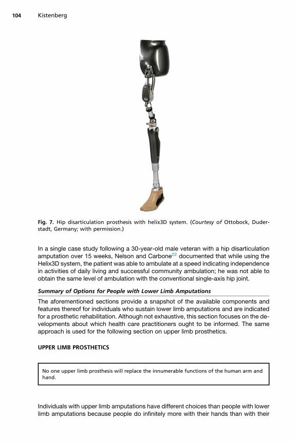
Fig. 7. Hip disarticulation prosthesis with helix3D system. (Courtesy of Ottobock, Duder-stadt, Germany; with permission.)
Kistenberg104
In a single case study following a 30-year-old male veteran with a hip disarticulationamputation over 15 weeks, Nelson and Carbone22 documented that while using theHelix3D system, the patient was able to ambulate at a speed indicating independencein activities of daily living and successful community ambulation; he was not able toobtain the same level of ambulation with the conventional single-axis hip joint.
Summary of Options for People with Lower Limb Amputations
The aforementioned sections provide a snapshot of the available components andfeatures thereof for individuals who sustain lower limb amputations and are indicatedfor a prosthetic rehabilitation. Although not exhaustive, this section focuses on the de-velopments about which health care practitioners ought to be informed. The sameapproach is used for the following section on upper limb prosthetics.
UPPER LIMB PROSTHETICS
No one upper limb prosthesis will replace the innumerable functions of the human arm andhand.
Individuals with upper limb amputations have different choices than people with lowerlimb amputations because people do infinitely more with their hands than with their
Choices for People with Leg and Arm Amputations 105
feet. Upper limb prostheses do not restore the lost functions of the arms to the extentthat lower limb prostheses do for legs. Choosing not to wear a lower limb prosthesisleaves one with the options of wheelchair ambulation, hopping with a walker or aswing-through gait on crutches. One’s quality of life, mobility, and independence isdefinitely impacted.For unilateral upper limb amputations, choosing not to wear a prosthesis leaves one
one-handed in a two-handed world but may have minimal to no effect on mobility orindependence. The effect of an upper limb amputation on one’s quality of life, how-ever, is as varied as the people who have upper limb amputations. A concert pianisthas a finger amputated and he or she is devastated. Another person may displayhis or her lost finger as a badge of courage.The emphasis for prosthetic rehabilitation for people with upper limb amputations
should be that a prosthesis is a tool to facilitate goal attainment and that different de-signs may be necessary to achieve different goals. Put another way, no one upper limbprosthesis will replace the innumerable functions of the human arm and hand. Multipleterminal devices and/or multiple prostheses may be required. If an individual’s pros-thetic rehabilitation plan is designed to facilitate realistic goals and a prosthesisenables them to achieve those goals, rejection should only occur when one’s goalshave changed. Unstated or poorly defined goals are a direct path to prosthetic rejec-tion. Furthermore, the role of occupational therapy cannot be overemphasized when itcomes to upper limb prosthetic rehabilitation.The following sections introduce different styles of prostheses (functional aesthetic
and activity specific), strategies for control (body powered vs externally powered), andoptions for people with upper limb amputations at different levels of amputation.
Functional Aesthetic Prostheses
Often people with new upper limb amputations feel awkward in social situationsbecause they struggle to incorporate their new physical appearance into their self-image. Provision of an aesthetic restoration for either a finger or a complete arm willallow people with amputations to perform the illusion that they have not had an ampu-tation by restoring a normal appearance. It should be emphasized that this type ofprosthesis is aesthetic (referring to natural beauty) rather than cosmetic (referring tonot substantive or superficial). This type of prosthesis may serve as a means to facil-itate acceptance and return to a premorbid social life. They may be used full time oronly on occasion.If one becomes socially reclusive as a result of their amputation or outward appear-
ance and provision of a prosthesis facilitates the return to social engagement, thatprosthesis has served an extraordinarily valuable function. Another functional benefitof aesthetic prostheses is that, although they may not be actively prehensile, they dorestore the ability to perform bimanual activities for those with unilateral amputations.For people with finger amputations, silicone aesthetic finger prostheses fill a void leftby the amputated digits, allowing secure grasp of small items, such as coins. Peoplewith amputations at the wrist or higher can use a functional aesthetic prosthesis tohold objects by placing them into a prepositioned hand or by wedging items betweenthe prosthesis and the wearer’s torso.Operation of functional aesthetic prostheses is achieved through manipulation by
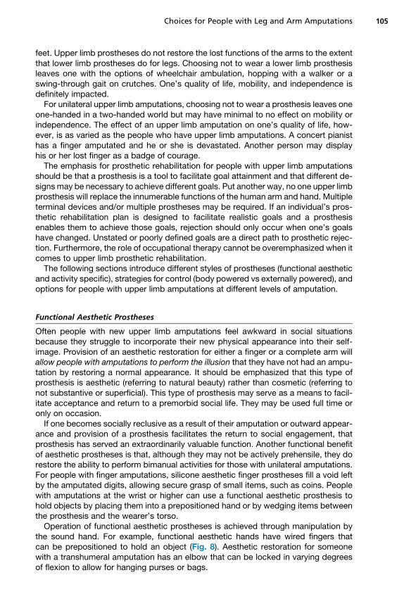
the sound hand. For example, functional aesthetic hands have wired fingers thatcan be prepositioned to hold an object (Fig. 8). Aesthetic restoration for someonewith a transhumeral amputation has an elbow that can be locked in varying degreesof flexion to allow for hanging purses or bags.
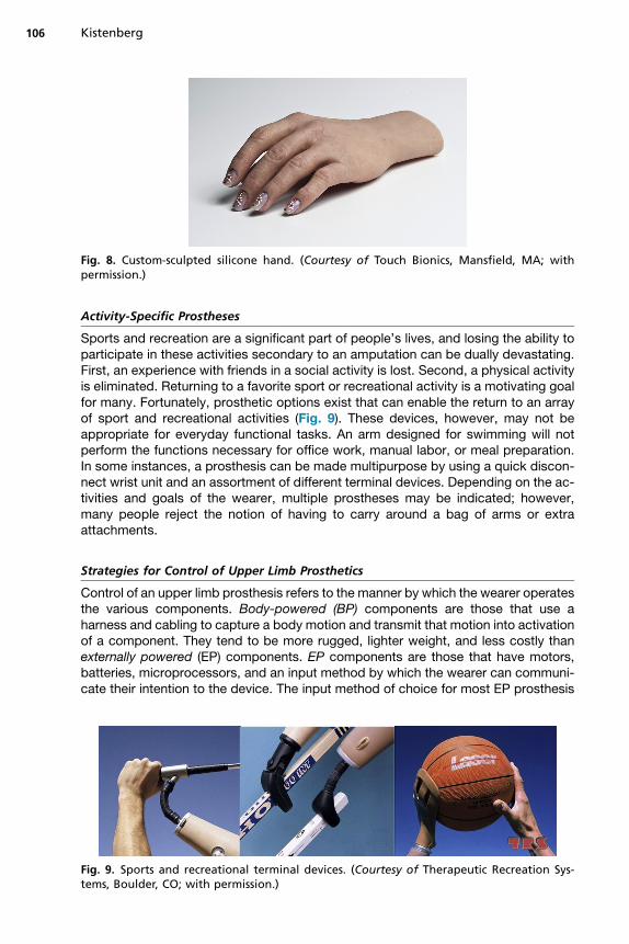
Fig. 8. Custom-sculpted silicone hand. (Courtesy of Touch Bionics, Mansfield, MA; withpermission.)
Kistenberg106
Activity-Specific Prostheses
Sports and recreation are a significant part of people’s lives, and losing the ability toparticipate in these activities secondary to an amputation can be dually devastating.First, an experience with friends in a social activity is lost. Second, a physical activityis eliminated. Returning to a favorite sport or recreational activity is a motivating goalfor many. Fortunately, prosthetic options exist that can enable the return to an arrayof sport and recreational activities (Fig. 9). These devices, however, may not beappropriate for everyday functional tasks. An arm designed for swimming will notperform the functions necessary for office work, manual labor, or meal preparation.In some instances, a prosthesis can be made multipurpose by using a quick discon-nect wrist unit and an assortment of different terminal devices. Depending on the ac-tivities and goals of the wearer, multiple prostheses may be indicated; however,many people reject the notion of having to carry around a bag of arms or extraattachments.
Strategies for Control of Upper Limb Prosthetics
Control of an upper limb prosthesis refers to the manner by which the wearer operatesthe various components. Body-powered (BP) components are those that use aharness and cabling to capture a body motion and transmit that motion into activationof a component. They tend to be more rugged, lighter weight, and less costly thanexternally powered (EP) components. EP components are those that have motors,batteries, microprocessors, and an input method by which the wearer can communi-cate their intention to the device. The input method of choice for most EP prosthesis
Fig. 9. Sports and recreational terminal devices. (Courtesy of Therapeutic Recreation Sys-tems, Boulder, CO; with permission.)
Choices for People with Leg and Arm Amputations 107
wearers is surface electrodes. Because these electrodes use electromyography(EMG) signals, EP prostheses are also referred to asmyoelectric prostheses; however,not all EP prostheses are myoelectric because other input types are available. Forpeople who require independent control of multiple components, for example, anelbow, wrist, and hand, hybrid-powered prostheses use a combination of EP andBP. The terminal device may be EP, whereas the elbow may be BP.Taken together, functional-aesthetic, activity-specific, BP, EP, and hybrid-powered
prostheses compose the 5 prosthetic options available for people with upper limbamputations. A sixth option is to choose not to wear a prosthesis at all. The followingsections detail options available according to amputation level.
Options for Thumb, Finger, and Partial Hand Amputations
One’s response to having an amputation is in no way proportional to the amount ofamputation they sustain.
Historically, finger and partial hand amputations have been disregarded becauseprosthetic options have been few due to space limitations. Functional aesthetic op-tions are available for people with finger and partial hand amputations. Both BP andEP prosthetic options exist for people with partial hand amputations.Because the thumb and fingers compose 90% of human arm function,23 the loss
of one or more fingers has an effect on hand function. Custom-sculpted, hand-painted silicone digits not only restore a realistic appearance but they also offercompression and desensitization for residual fingers. These aesthetic restorationsfacilitate grasp by providing a textured, high-friction surface. Special considerationsneed to be made for thumb amputations because opposition is either diminished orlost. In some cases, an opposition post will facilitate grasp with the remainingdigits.BP options for digital and partial hand amputations attempt to harness either meta-
carpophalangeal or wrist flexion/extension to drive prosthetic digits. Grip force islimited to the strength attainable by these motions. Aesthetics for these types of pros-theses may be sacrificed in lieu of function.EP options for partial hand amputations are available for amputations of the thumb
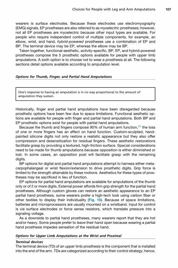
only or of 2 or more digits. External power affords firm grip strength for the partial handprostheses. Although custom gloves can restore an aesthetic appearance to an EPpartial hand prosthesis, some wearers prefer a high-tech look using carbon fiber orother textiles to display their individuality (Fig. 10). Because of space limitations,batteries and microprocessors are usually mounted on a wristband. Input for controlis via surface electrodes or force sense resistors, which translate pressure into asignaling voltage.As a downside to partial hand prostheses, many wearers report that they are hot
and/or heavy. Some people prefer to leave their hand open because wearing a partialhand prosthesis impedes sensation of the residual hand.
Options for Upper Limb Amputations at the Wrist and Proximal
Terminal devicesThe terminal device (TD) of an upper limb prosthesis is the component that is installedinto the end of the arm. TDs are categorized according to their control strategy; hence,
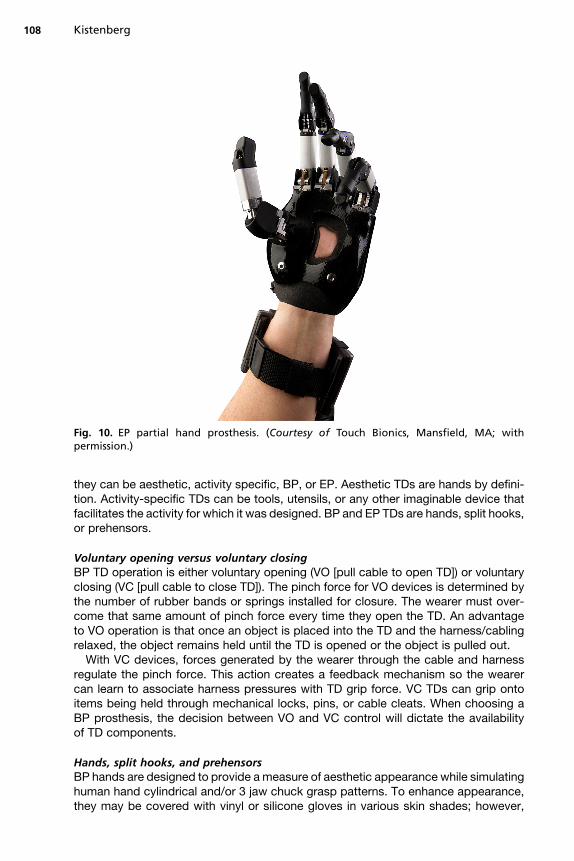
Fig. 10. EP partial hand prosthesis. (Courtesy of Touch Bionics, Mansfield, MA; withpermission.)
Kistenberg108
they can be aesthetic, activity specific, BP, or EP. Aesthetic TDs are hands by defini-tion. Activity-specific TDs can be tools, utensils, or any other imaginable device thatfacilitates the activity for which it was designed. BP and EP TDs are hands, split hooks,or prehensors.
Voluntary opening versus voluntary closingBP TD operation is either voluntary opening (VO [pull cable to open TD]) or voluntaryclosing (VC [pull cable to close TD]). The pinch force for VO devices is determined bythe number of rubber bands or springs installed for closure. The wearer must over-come that same amount of pinch force every time they open the TD. An advantageto VO operation is that once an object is placed into the TD and the harness/cablingrelaxed, the object remains held until the TD is opened or the object is pulled out.With VC devices, forces generated by the wearer through the cable and harness
regulate the pinch force. This action creates a feedback mechanism so the wearercan learn to associate harness pressures with TD grip force. VC TDs can grip ontoitems being held through mechanical locks, pins, or cable cleats. When choosing aBP prosthesis, the decision between VO and VC control will dictate the availabilityof TD components.
Hands, split hooks, and prehensorsBP hands are designed to provide ameasure of aesthetic appearance while simulatinghuman hand cylindrical and/or 3 jaw chuck grasp patterns. To enhance appearance,they may be covered with vinyl or silicone gloves in various skin shades; however,
Choices for People with Leg and Arm Amputations 109
some BP hands are aesthetically sculpted and do not require a glove. The disadvan-tages of BP hands are that they are visually obstructive, lack fine-tip prehension, andare comparatively heavy. BP split hooks are not visually obstructive and excel only atfine-tip prehension and lateral prehension. Hooks are lightweight and come in an arrayof sizes, shapes, and materials depending on the functional demands of the user. Theaesthetics of a hook, however, may lead some to reject this as an option outright.BP prehensors appear similar to split hooks, but in operation they move similar to a
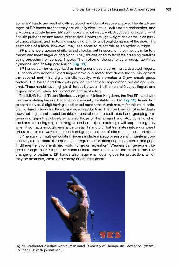
thumb and index finger during pinch. They are designed to facilitate grasping patternsusing opposing nonidentical fingers. The motion of the prehensors’ grasp facilitatescylindrical and fine-tip prehension (Fig. 11).EP hands can be categorized as having nonarticulated or multiarticulated fingers.
EP hands with nonarticulated fingers have one motor that drives the thumb againstthe second and third digits simultaneously, which creates a 3-jaw chuck grasppattern. The fourth and fifth digits provide an aesthetic appearance but are not pow-ered. These hands have high pinch forces between the thumb and 2 active fingers andrequire an outer glove for protection and aesthetics.The iLIMB Hand (Touch Bionics, Livingston, United Kingdom), the first EP hand with
multi-articulating fingers, became commercially available in 2007 (Fig. 12). In additionto each individual digit having a dedicated motor, the thumb mount for this multi-artic-ulating hand allows for thumb abduction/adduction. The combination of individuallypowered digits and a positionable, opposable thumb facilitates hand grasping pat-terns and grips that closely simulated those of the human hand. Additionally, whenthe hand is closing (digits flexing) around an object, each digit will stop closing onlywhen it contacts enough resistance to stall its’ motor. That translates into a compliantgrip similar to the way the human hand grasps objects of different shapes and sizes.EP hands with multi-articulating fingers include microprocessors with wireless con-
nectivity that facilitate the hand to be programed for different grasp patterns and gripsin different environments (ie, work, home, or recreation). Wearers can generate trig-gers through the EP inputs to communicate their intention to the hand in order tochange grip patterns. EP hands also require an outer glove for protection, whichmay be aesthetic, clear, or a variety of different colors.
Fig. 11. Prehensor overlaid with human hand. (Courtesy of Therapeutic Recreation Systems,Boulder, CO; with permission.)
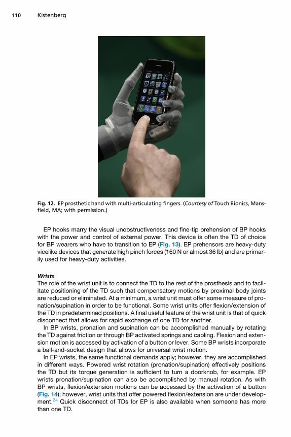
Fig. 12. EP prosthetic hand with multi-articulating fingers. (Courtesy of Touch Bionics, Mans-field, MA; with permission.)
Kistenberg110
EP hooks marry the visual unobstructiveness and fine-tip prehension of BP hookswith the power and control of external power. This device is often the TD of choicefor BP wearers who have to transition to EP (Fig. 13). EP prehensors are heavy-dutyvicelike devices that generate high pinch forces (160 N or almost 36 lb) and are primar-ily used for heavy-duty activities.
WristsThe role of the wrist unit is to connect the TD to the rest of the prosthesis and to facil-itate positioning of the TD such that compensatory motions by proximal body jointsare reduced or eliminated. At a minimum, a wrist unit must offer some measure of pro-nation/supination in order to be functional. Some wrist units offer flexion/extension ofthe TD in predetermined positions. A final useful feature of the wrist unit is that of quickdisconnect that allows for rapid exchange of one TD for another.In BP wrists, pronation and supination can be accomplished manually by rotating
the TD against friction or through BP activated springs and cabling. Flexion and exten-sion motion is accessed by activation of a button or lever. Some BP wrists incorporatea ball-and-socket design that allows for universal wrist motion.In EP wrists, the same functional demands apply; however, they are accomplished
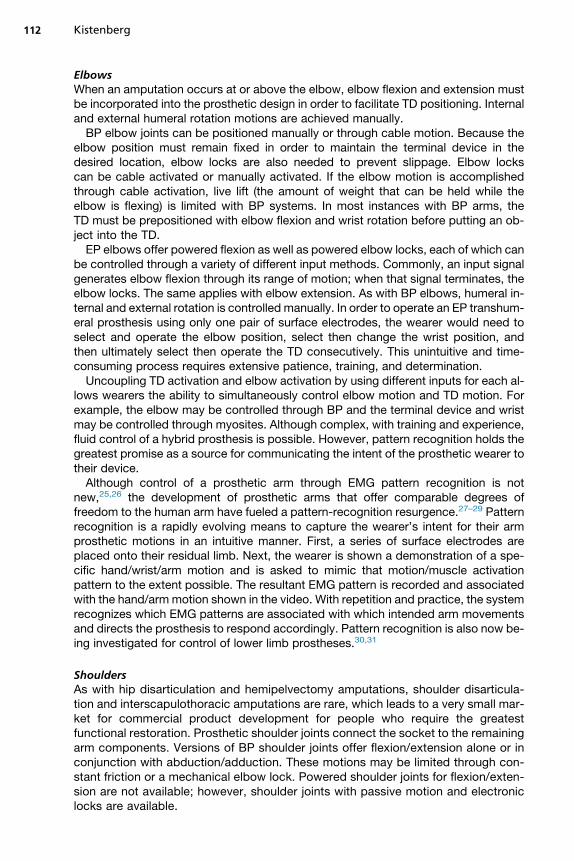
in different ways. Powered wrist rotation (pronation/supination) effectively positionsthe TD but its torque generation is sufficient to turn a doorknob, for example. EPwrists pronation/supination can also be accomplished by manual rotation. As withBP wrists, flexion/extension motions can be accessed by the activation of a button(Fig. 14); however, wrist units that offer powered flexion/extension are under develop-ment.24 Quick disconnect of TDs for EP is also available when someone has morethan one TD.
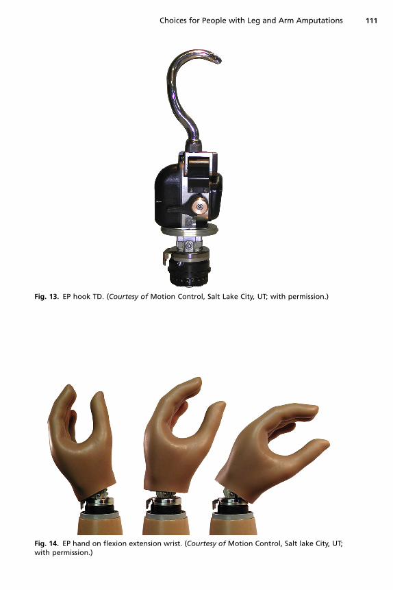
Fig. 13. EP hook TD. (Courtesy of Motion Control, Salt Lake City, UT; with permission.)
Fig. 14. EP hand on flexion extension wrist. (Courtesy of Motion Control, Salt lake City, UT;with permission.)
Choices for People with Leg and Arm Amputations 111
Kistenberg112
ElbowsWhen an amputation occurs at or above the elbow, elbow flexion and extension mustbe incorporated into the prosthetic design in order to facilitate TD positioning. Internaland external humeral rotation motions are achieved manually.BP elbow joints can be positioned manually or through cable motion. Because the
elbow position must remain fixed in order to maintain the terminal device in thedesired location, elbow locks are also needed to prevent slippage. Elbow lockscan be cable activated or manually activated. If the elbow motion is accomplishedthrough cable activation, live lift (the amount of weight that can be held while theelbow is flexing) is limited with BP systems. In most instances with BP arms, theTD must be prepositioned with elbow flexion and wrist rotation before putting an ob-ject into the TD.EP elbows offer powered flexion as well as powered elbow locks, each of which can
be controlled through a variety of different input methods. Commonly, an input signalgenerates elbow flexion through its range of motion; when that signal terminates, theelbow locks. The same applies with elbow extension. As with BP elbows, humeral in-ternal and external rotation is controlled manually. In order to operate an EP transhum-eral prosthesis using only one pair of surface electrodes, the wearer would need toselect and operate the elbow position, select then change the wrist position, andthen ultimately select then operate the TD consecutively. This unintuitive and time-consuming process requires extensive patience, training, and determination.Uncoupling TD activation and elbow activation by using different inputs for each al-
lows wearers the ability to simultaneously control elbow motion and TD motion. Forexample, the elbow may be controlled through BP and the terminal device and wristmay be controlled through myosites. Although complex, with training and experience,fluid control of a hybrid prosthesis is possible. However, pattern recognition holds thegreatest promise as a source for communicating the intent of the prosthetic wearer totheir device.Although control of a prosthetic arm through EMG pattern recognition is not
new,25,26 the development of prosthetic arms that offer comparable degrees offreedom to the human arm have fueled a pattern-recognition resurgence.27–29 Patternrecognition is a rapidly evolving means to capture the wearer’s intent for their armprosthetic motions in an intuitive manner. First, a series of surface electrodes areplaced onto their residual limb. Next, the wearer is shown a demonstration of a spe-cific hand/wrist/arm motion and is asked to mimic that motion/muscle activationpattern to the extent possible. The resultant EMG pattern is recorded and associatedwith the hand/armmotion shown in the video. With repetition and practice, the systemrecognizes which EMG patterns are associated with which intended arm movementsand directs the prosthesis to respond accordingly. Pattern recognition is also now be-ing investigated for control of lower limb prostheses.30,31
ShouldersAs with hip disarticulation and hemipelvectomy amputations, shoulder disarticula-tion and interscapulothoracic amputations are rare, which leads to a very small mar-ket for commercial product development for people who require the greatestfunctional restoration. Prosthetic shoulder joints connect the socket to the remainingarm components. Versions of BP shoulder joints offer flexion/extension alone or inconjunction with abduction/adduction. These motions may be limited through con-stant friction or a mechanical elbow lock. Powered shoulder joints for flexion/exten-sion are not available; however, shoulder joints with passive motion and electroniclocks are available.
Choices for People with Leg and Arm Amputations 113
Options for People with Bilateral Upper Limb Amputations
People with bilateral upper limb amputations often rely on prosthetic arms for their ac-tivities of daily living and independence, making their choices related to prosthesisdesign emphasize reliability, operational control, and prehension. As a result, BP sys-tems are often recommended as the primary set of prostheses. Even with a functionalset of prosthetic arms, additional modifications to home and work are necessary forindependence. If a BP set of arms proves unable to meet basic functional needs, addi-tional prostheses with external power, hybrid power, and/or are activity specific maybe indicated.
CHOOSING TO GO WITHOUT
First and foremost, it must be acknowledged that choosing not to wear a prosthesis isperfectly acceptable as long as it is a choice. For people with upper extremity ampu-tations, the best arm prosthesis available today still cannot feel the warmth and textureof a gentle caress. Wheelchair ambulation or crutches may be the best option whencompared with the high energetic cost of ambulation with a prosthesis (or prostheses)for someone who has a high-level lower extremity amputation, bilateral amputations,or who is systemically compromised. However, before one is resigned to living onehanded in a 2-handed world or going without a lower limb prosthesis, they shouldat least be given the opportunity to try using a prosthesis if indicated. They thenhave the ability to make an informed decision about when to wear, or not wear, an arti-ficial limb.
SUMMARY
The definition of success in prosthetic rehabilitation is variable. If a person with anamputation has a prosthesis designed for weight lifting that they use for 45 minutesa day, 3 times a week and it allows them the ability to exercise, a successful outcomehas been achieved. If a prosthesis is designed to allow someone to work in an indus-trial job for 40 hours a week but it is only tolerable for 38 hours, that is an unsuccessfuloutcome. Success must be defined on an individual basis.Prosthetic rehabilitation is also nonlinear. Amputated limbs must heal. To get
beyond grief, one must go through grief. Progress will be made and progress willbe lost. Individuals who use a prosthesis must learn how to operate and maintaintheir prosthesis. As balance is recovered and residual limbs change, so too mustthe prosthesis be altered or replaced. Physical, occupational, and often mentalhealth therapy are critical to facilitating the adjustment to one’s disability and opti-mizing the remaining anatomy and physiologic reserves in preparation for prostheticfitting and training.Careful attention must be paid to the realistic expectations of everyone involved to
prevent rejection and disappointment. Every member of the rehabilitation team isresponsible for identifying and accurately setting expectations. On the day of pros-thetic delivery, if patients’ expectations exceed that which the clinical team candeliver, serious problems arise. If patients’ expectations are set at or less than thatwhich the clinical team can deliver, prosthetic rehabilitation will result in optimal out-comes and success.Although this article details the numerous options that exist for individuals with
amputations, the choices that determine the type of prosthesis someone wears, ifthey choose to wear one, must be made in consideration of specific goals and inconjunction with a rehabilitation team. The undercurrent that must be acknowledged
Kistenberg114
for every person who receives a prosthesis is that the device itself is neither a magicsalve that, once received and perfected, will restore them to who they were beforetheir amputation nor a superhuman technology that will transform them into a bionicwoman or man. The prosthesis is simply a component of an overall rehabilitationplan that is centered around the person with the amputation and requires a team ofhealth care professionals in order to successfully execute.
REFERENCES
1. Board W, Street GM, Caspers C. A comparison of transtibial amputee suction andvacuum socket conditions. Prosthet Orthot Int 2001;25:202–9.
2. Goswami J, Lynn R, Street G, et al. Walking in a vacuum-assisted socket shiftsthe stump fluid balance. Prosthet Orthot Int 2003;27(2):107–13.
3. Gerschutz MJ, Denune JA, Colvin JM, et al. Elevated vacuum suspension influ-ence on lower limb amputee’s residual limb volume at different vacuum pressuresettings. J Prosthet Orthot 2010;22(4):252–6.
4. Sanders JE, Harrison DS, Myers TR, et al. Effects of elevated vacuum on in-socket residual limb fluid volume: case study results using bioimpedance anal-ysis. J Rehabil Res Dev 2011;48(10):1231–48.
5. Hoskins RD, Sutton EE, Kinor D, et al. Using vacuum-assisted suspension tomanage residual limb wounds in persons with transtibial amputation: a caseseries. Prosthet Orthot Int 2013. [Epub ahead of print].
6. Pantall A, Ewins D. Muscle activity during stance phase of walking: comparison ofmales with transfemoral amputation with osseointegrated fixations to nondisabledmale volunteers. J Rehabil Res Dev 2013;50(4):499–514.
7. Rosenbaum-Chou T. Update on osseointegration for prosthetic attachment.Academy Today 2013;9(2):A9–11.
8. American Orthotic and Prosthetic Association. AOPA prosthetic foot projectreport. 2010. Available at: http://www.aopanet.org/Prosthetic_Foot_Project.pdf.
9. Czerniecki JM. Research and clinical selection of foot-ankle systems. J ProsthetOrthot 2005;17(4S):35–7.
10. Daher R. Physical response of SACH feet under laboratory testing. Bull ProsthetRes 1975;10–23(Spring):4–50.
11. Sowell T. A preliminary clinical evaluation of the Mauch hydraulic foot-ankle sys-tem. Prosthet Orthot Int 1981;5(2):87–91.
12. Herr HM, Grabowski AM. Bionic ankle-foot prosthesis normalizes walking gait forpersons with leg amputation. Proc Biol Sci 2012;279(1728):457–64. http://dx.doi.org/10.1098/rspb.2011.1194. PubMed PMID: 21752817; PubMed Central PMCID:PMCPMC3234569.
13. Williams RM, Turner AP, Orendurff M, et al. Does having a computerized pros-thetic knee influence cognitive performance during amputee walking? ArchPhys Med Rehabil 2006;87(7):989–94. http://dx.doi.org/10.1016/j.apmr.2006.03.006. PubMed PMID: 16813788.
14. Hafner BJ, Willingham LL, Buell NC, et al. Evaluation of function, performance,and preference as transfemoral amputees transition from mechanical to micro-processor control of the prosthetic knee. Arch Phys Med Rehabil 2007;88(2):207–17. http://dx.doi.org/10.1016/j.apmr.2006.10.030. PubMed PMID: 17270519.
15. Greene MP. Four bar linkage knee analysis. Orthotics and Prosthetics 1983;37(1):15–24.
16. Saunders M, Inman V, Eberhart H. The major determinants in normal and patho-logical gait. J Bone Joint Surg Am 1953;35(3):543–58.
Choices for People with Leg and Arm Amputations 115
17. Gard SA, Childress DS. The influence of stance-phase knee flexion on the verticaldisplacement of the trunk during normal walking. Arch Phys Med Rehabil 1999;80(1):26–32.
18. Ebrahimzadeh MH, Rajabi MT. Long-term outcomes of patients undergoing war-related amputations of the foot and ankle. J Foot Ankle Surg 2007;46(6):429–33.
19. Ephraim PL, Wegener ST, MacKenzie EJ, et al. Phantom pain, residual limb pain,and back pain in amputees: results of a national survey. Arch Phys Med Rehabil2005;86(10):1910–9.
20. Wolf EJ, Everding VQ, Linberg AL, et al. Assessment of transfemoral amputeesusing C-Leg and Power Knee for ascending and descending inclines and steps.J Rehabil Res Dev 2012;49(6):831–42.
21. Wolf EJ, Everding VQ, Linberg AA, et al. Comparison of the power knee andC-Leg during step-up and sit-to-stand tasks. Gait Posture 2013;38(3):397–402.Available at: http://dx.doi.org/10.1016/j.gaitpost.2013.01.007.
22. Nelson LM, Carbone NT. Functional outcome measurements of a veteran with ahip disarticulation using a Helix 3D hip joint: a case report. J Prosthet Orthot2011;23(1):21–6.
23. Cocchiarella L, Andersson GB, editors. Guides to the evaluation of permanentimpairment. 5th edition. Chicago: AMA Press; 2001.
24. Kyberd PJ, Lemaire ED, Scheme E, et al. Two-degree-of-freedom poweredprosthetic wrist. J Rehabil Res Dev 2010;48(6):609–17.
25. Lee S, Saridis G. The control of a prosthetic arm by EMG pattern recognition.IEEE Trans Automat Contr 1984;29(4):290–302.
26. Wirta RW, Taylor DR, Finley FR. Pattern recognition arm prosthesis: a historicalperspective-a final report. Bull Prosthet Res 1978;10(30):8–35.
27. Scheme E, Englehart K. Electromyogram pattern recognition for control ofpowered upper-limb prostheses: state of the art and challenges for clinicaluse. J Rehabil Res Dev 2010;48(6):643–59.
28. Hargrove LJ, Lock BA, Simon AM, editors. Pattern recognition control outper-forms conventional myoelectric control in upper limb patients with targetedmuscle reinnervation. Engineering in Medicine and Biology Society (EMBC),2013 35th Annual International Conference of the IEEE. Osaka, Japan, 3–7July, 2013: IEEE.
29. Radmand A, Scheme E, Kyberd P, et al. Investigation of optimum pattern recog-nition methods for robust myoelectric control during dynamic limb movement.Evaluation 1500:12. May, 2013.
30. Du L, Zhang F, He H, et al, editors. Improving the performance of a neural-machine interface for prosthetic legs using adaptive pattern classifiers.Engineering in Medicine and Biology Society (EMBC), 2013 35th Annual Interna-tional Conference of the IEEE. Osaka, Japan, 3–7 July, 2013: IEEE.
31. Hargrove LJ, Simon AM, Lipschutz R, et al. Non-weight-bearing neural control ofa powered transfemoral prosthesis. J Neuroeng Rehabil 2013;10:62. http://dx.doi.org/10.1186/1743-0003-10-62. PubMed PMID: WOS:000321580300001.