Embed Size (px)
Citation preview
DESIGN OF AN ACTIVE FOOT FOR A SMART PROSTHETIC LEG
Vom Fachbereich Maschinenbau
an der Technischen Universität Darmstadt
zur
Erlangung des Grades eines Doktor-Ingenieurs (Dr.-Ing.)
genehmigte
D i s s e r t a t i o n
Vorgelegt von
Dipl.-Ing. Valerio Carli
aus Rom
Berichterstatter: Prof. Dr.-Ing. Holger Hanselka
Mitberichterstatter: Prof. Dr.-Ing. Rainer Nordmann
Tag der Einreichung: 31.10.2006
Tag der mündlichen Prüfung: 12.12.2006
Darmstadt 2007
D 17
ABSTRACT
The purpose of this project is the realisation of a prosthetic foot, able to adapt to the different conditions encountered by the patient during walking. The analysis of the human gait shows that a normal foot has the capability to assume an optimised shape. Coordinated movements of body parts, together with the shape assumed by the foot, result in minimising the energy expenditure during walking. Concerning the prosthetic foot, the bending stiffness of the plantar spring is the quantity to vary, in order to achieve the desired change in foot properties.
Three different concepts are investigated: The first one deals with the possibility of adjusting the static response of the plantar spring of the foot by means of solid-state actuators. Piezoceramic patches are employed as active elements which are able to change the shape of the plantar spring.
The second concept takes advantage of the property of a hollow beam with an ellipticalal cross- section. Depending on the value of the inner pressure applied, the ellipticalal cross-section deforms, resulting in a change in the moment of inertia of the cross-section itself. The deformation of the cross-section, due to the inner pressure, leads to an increased bending stiffness of the structure. The behaviour of an integrated structure made of a passive plate and of active beams is numerically and experimentally analysed.
The third concept is based on the possibility of controlling the deformation of a flat hollow structure while under a bending load. The conventional plantar spring is replaced by a thin structure consisting of two parallel plates. The space between the plates is filled with a hydraulic fluid to generate inner pressure. Due to the shear stiffness of the structure, the bending load leads to the inward deformation of the plate assuming the shorter radius of curvature. The inner pressure stiffens the structure by controlling the inward displacement of the plate.
A system for generating the pressure is presented. The system is activated by the patient and takes advantage of the work performed during the stance phase. The system is integrated in the foot structure and may replace the conventional ankle joint of the prosthetic foot.
ZUSAMMENFASSUNG
Der Zweck dieser Arbeit ist die Realisierung eines prothetischen Fußes, der sich an den verschiedenen Bedingungen während des Laufens anpassen kann. Die Analyse der menschlichen Gehweise zeigt, dass der natürliche Fuß die Fähigkeit hat, eine optimierte Gestalt anzunehmen. Die optimierte Gestalt des Fußes zusammen mit anderen koordinierten Bewegungen der Körperteile führt zu einer Minimierung des Energieverbrauchs während des Laufens. Die Biegesteifigkeit der Basisfeder des prothetischen Fußes stellt die zu ändernde Größe dar, um die gewünschte Änderung der Fußeigenschaften zu erreichen.
Drei verschiedene Konzepte werden untersucht: Das erste Konzept befasst sich mit der Möglichkeit, die statische Antwort der Basisfeder des Fußes mittels Festkörperaktoren zu ändern. Hierbei werden Piezokeramische Platten als aktive Elemente verwendet, welche dann in der Lage sind, die Gestalt der Basisfeder zu variieren.
Das zweite Konzept nutzt die Eigenschaften eines hohlen Balkens mit einem elliptischen Querschnitt aus. Die Verformung des elliptischen Querschnitts erfolgt durch den applizierten Innendruck. Folge der elastischen Verformung ist die Erhöhung des Trägheitsmoments des Querschnitts. Wegen der durch den Innendruck generierten Verzerrung des Querschnitts, wird die Biegesteifigkeit der Struktur erhöht. Das mechanische Verhalten einer aus passiver Platte und aktiven Balken bestehenden integrierten Struktur wird numerisch und experimentell untersucht.
Das dritte Konzept beruht auf der Möglichkeit, die Verformung einer mit einer Biegekraft belasteten flachen, hohlen Struktur zu kontrollieren. Die herkömmliche Basisfeder wird durch eine aus zwei Platten bestehende dünne Struktur ersetzt. Um den Innendruck zu erzeugen, wird der Raum zwischen den Platten mit Hydrauliköl gefüllt. Infolge der Schubsteifigkeit der Struktur, führt die Biegelast dazu, dass die Platte, die den kürzeren Krümmungsradius annimmt, sich nach innen verformt. Die Versteifung der Struktur erfolgt durch die durch den Innendruck kontrollierte Verformung der Platte.
Es wird ein System entworfen, um den Druck zu erzeugen. Das System wird vom Patienten selbst aktiviert und nutzt die während der Standphase durchgeführte Arbeit aus. Das System wird in die Fußstruktur integriert und kann das herkömmliche Knöchel-Gelenk des prothetischen Fußes ersetzen.
CONTENTS
1. Introduction .................................................................................................................................................. 2 1.1. Basics of the human gait............................................................................................................... 2 1.2. Description of human locomotion............................................................................................. 2 1.3. The human locomotion as energy-efficient movement ......................................................... 5 1.4. The function of the prosthetic limb........................................................................................... 8 1.5. State of the art .............................................................................................................................. 11 1.6. Objective of the project.............................................................................................................. 13
2. The reference model.................................................................................................................................. 17 2.1. Description and analysis of the available foot........................................................................ 17 2.2. Definition of the load condition acting on the foot during stance .................................... 18 2.3. Definition of the finite element model and numerical results............................................. 19
3. The first concept: Static adjustment by means of piezoceramic patches ........................................ 23 3.1. Introduction to the adaptive prosthetic foot.......................................................................... 23 3.2. Active change in foot bending stiffness by means of piezoceramic elements ................. 23 3.3. Numerical results of the proposed concept............................................................................ 28
4. The second concept: The plantar spring based on the active elliptical tubes................................. 34 4.1. Change in Young’s modulus...................................................................................................... 35 4.2. Change in the moment of inertia of the beam cross-section .............................................. 35 4.3. Deformation of the elliptical cross-section............................................................................. 37 4.4. Numerical analysis of the 2D deformation of the elliptical cross-section ........................ 38 4.5. The active change in the bending stiffness of the elliptical cylinder .................................. 42 4.6. Experimental verification of the numerical analysis of the elliptical cross-section ......... 44 4.7. Design of the adaptive prosthetic foot based on the previous concept............................ 46 4.8. Numerical evaluation of the active change in bending stiffness......................................... 52 4.9. Optimising the thickness distribution of the lower plate ..................................................... 54 4.10. Manufacturing of the active foot .............................................................................................. 59 4.11. Results of experiment ................................................................................................................. 62 4.12. Results of the test performed by the patient .......................................................................... 65 4.13. Critical review of the results....................................................................................................... 66
5. The third concept: The active plantar spring based on a single flat tube........................................ 69 5.1. Motivation for a new concept ................................................................................................... 69 5.2. The new concept for the active plantar spring....................................................................... 69 5.3. Design of the new plantar spring.............................................................................................. 71 5.4. Numerical model of the first prototype of the plantar spring............................................. 73 5.5. Numerical results of the first prototype .................................................................................. 76 5.6. Manufacturing the prototype and results of experiment...................................................... 78 5.7. Test performed by the patient................................................................................................... 81 5.8. Evolution of the previous concept: The second prototype................................................. 82 5.9. Manufacturing the second prototype and results of experiment........................................ 84 5.10. The third prototype ..................................................................................................................... 85 5.11. Experimental validation of the numerical results .................................................................. 87 5.12. Test performed by the patient................................................................................................... 87 5.13. Summary of the characteristics of the prototypes and related results ............................... 88
6. Design of an integrated system for the operation of the active foot ............................................... 91 6.1. The foot as an adaptive system................................................................................................. 91 6.2. Design of the pumping system ................................................................................................. 94 6.3. The equation describing the system ......................................................................................... 96 6.4. Condition for the stiffness K2 ................................................................................................. 100
I
6.5. Results of simulation and performance of the system........................................................ 100 6.6. Coupling of the system with the foot .................................................................................... 103 6.7. Conclusions................................................................................................................................. 105
7. Evaluation of the results and conclusions........................................................................................... 107 Appendix I: Material properties of the carbon fibre and glass fibre composite materials ................ 109
II
LIST OF FIGURES
Fig.: 1-1: Phases of gait cycle, according to [1.1]........................................................................................... 3 Fig. 1-2: Areas of the foot sole in contact with the ground during stance and position of the GRF,
according to [1.3] ................................................................................................................................ 4 Fig. 1-3: The vertical component of the GRF. Source: Otto Bock GmbH............................................. 5 Fig. 1-4: Energy expenditure according to [1.12]. TT: trans-tibial; TK: through-knee; TF: trans-
femoral; HD: hip disarticulation; HP: hemi-pelvectomy. The oxygen cost is measured in millilitres O2 per kilogram weight per meter covered by the patient........................................ 7
Fig. 1-5: The rocker-based inverted pendulum. “R” represents the radius of the rocker ..................... 8 Fig. 1-6: The prosthesis for a trans-femoral amputee. Source: Otto Bock GmbH................................ 9 Fig. 1-7: Stability of the knee joint of the prosthetic limb, according to [1.2] ....................................... 10 Fig. 1-8: Vertical component of the GRF of a woman. Mean body weight 66 kg. Source: Otto Bock
GmbH ................................................................................................................................................ 14 Fig. 2-1: The foot 1C40 made by Otto Bock GmbH ................................................................................ 17 Fig. 2-2: Time variation of the vertical component of the GRF and the corresponding bending
moment at the ankle. ....................................................................................................................... 18 Fig. 2-3: The finite element model of C-spring, plantar spring, and the global reference system. .... 19Fig. 2-4: The experimental tests performed on the C-spring and plantar spring. ................................. 20 Fig. 2-5: Left - Maximum negative strain in correspondence with the inner surface of the C-spring.
Right - Vertical displacement under the selected load condition. The red arrow shows the direction of the vertical force and its location ............................................................................ 21
Fig. 2-6: Vertical displacement of the foot under the second load condition and the corresponding deformation in X direction. The red arrow indicates the position and direction of the vertical load........................................................................................................................................ 21
Fig. 2-7: Deformed shape of the plantar spring compared to its undeformed configuration............ 22 Fig. 3-1: The beam-like plantar spring and piezoceramic layers in symmetrical configuration.......... 24Fig. 3-2: Strain distribution over the beam cross-section for the Euler-Bernoulli model. .................. 25 Fig. 3-3: The positive strain distribution on the lower side of the plantar spring for both
configurations. Upper figure: PI piezoelectric ceramic. Lower figure: Smart Material’s piezoelectric ceramic........................................................................................................................ 32
Fig. 4-1: The elliptical cross-section and its reference system, based on the reference system used for the plantar spring ....................................................................................................................... 37
Fig. 4-2: Radial displacement “w” of the elliptical cross-section, according to [4.6]............................ 38 Fig. 4-3: Orientation of the composite material fibres and polar diagram of its elastic properties ... 40Fig. 4-4: Change in the moment of inertia for the selected configuration, with t = 1.00 mm ........... 41Fig. 4-5: FE model of the active tube and the coupled lower plate......................................................... 42 Fig. 4-6: Change in the bending stiffness of the numerical model .......................................................... 43 Fig. 4-7: The deformed configuration of the cylinder and corresponding forces................................. 44 Fig. 4-8: The connection between the active tube and stiffening lower plate ....................................... 44 Fig. 4-9: The hydraulic components. ............................................................................................................. 45 Fig. 4-10: The experimental set-up for testing the active tube. ................................................................ 45 Fig. 4-11: Results of the experimental test ................................................................................................... 46 Fig. 4-12: Cross-section of the new active plantar spring.......................................................................... 47 Fig. 4-13: Thickness distribution of the old and new configurations of the plantar spring according
to (4.9) and (4.10) ............................................................................................................................. 49 Fig. 4-14: The finite element model of the new plantar spring ................................................................ 49 Fig. 4-15: Vertical displacement of the new plantar spring designed according to (4.9) and (4.10),
and of the plantar spring provided by Otto Bock GmbH. ...................................................... 50
III
Fig. 4-16: Thickness distribution of the conventional plantar spring and of the lower plate of the new plantar spring, according to (4.10) and (4.11)..................................................................... 51
Fig. 4-17: FEM model of the deformation of the new plantar spring (left) and old plantar springs (right). ................................................................................................................................................. 51
Fig. 4-18: Vertical displacement of the points of the centre line of the lower surface of the foot for 0 bar and 20 bar under the same load condition........................................................................ 53
Fig. 4-19: Deformation in X direction of the lower surface of the passive plate.................................. 54 Fig. 4-20: Thickness distribution of the analysed configurations............................................................. 57 Fig. 4-21: Stiffness distribution of the analysed configurations................................................................ 58 Fig. 4-22: Active change in bending stiffness for the different configurations. STOB correspond to
the model having the same bending stiffness distribution of the conventional plantar spring .................................................................................................................................................. 58
Fig. 4-23: The adaptive foot with the hydraulic parts, top view............................................................... 59 Fig. 4-24: The left and right hydraulic connecting elements. A: Elliptically shaped connecting part
for the tubes. B: Cylinders connecting the left and right elements to the central element. 61 Fig. 4-25: The hydraulic components screwed together............................................................................ 61 Fig. 4-26: The new plantar spring with the hydraulic parts. ...................................................................... 62 Fig. 4-27: The experimental set-up for testing the plantar spring............................................................ 63 Fig. 4-28: Comparison of the numerical and experimental results in bending stiffness of the new
plantar spring..................................................................................................................................... 64 Fig. 4-29: Experimental results of the active change in bending stiffness. First prototype ................ 64 Fig. 4-30: Experimental results of the active change in bending stiffness. Second prototype ........... 65 Fig. 4-31: The long-tube configuration ......................................................................................................... 67 Fig. 5-1: The structure made of two parallel plates as test structure for the new concept. The truss
elements are shown in the figure on the right............................................................................. 70 Fig. 5-2: Vertical displacement of the double-plate structure. Left - without stiffening truss
elements. Right – with the contribution of stiffening elements. The red arrow represents the bending load. .............................................................................................................................. 70
Fig. 5-3: The new plantar spring. The dimensions are in millimetres ..................................................... 72 Fig. 5-4: The cross-section of the new plantar spring and its elements .................................................. 72 Fig. 5-5: The shape and the thickness distribution of the carbon fibre stiffening plate ...................... 75 Fig. 5-6: FE model of the first prototype of the plantar spring. The red arrows represent the
distributed bending load and the triangles show the clamped cross-section of the model 76 Fig. 5-7: Vertical displacement of the plantar spring for 0 bar and for 5 bar. Results of the finite
element simulation. .......................................................................................................................... 77 Fig. 5-8: Vertical displacement of the lower points of the centre line of plantar spring for 0 bar and
for 5 bar.............................................................................................................................................. 77 Fig. 5-9: Rotation of the upper and lower nodes of the tube about the Z-axis of the global reference
system. ................................................................................................................................................ 78 Fig. 5-10: The closing elements. The figure on the left shows the connection to the external
hydraulic system................................................................................................................................ 79 Fig. 5-11: First prototype of the plantar spring and the complete foot with the non-return valve. .. 80Fig. 5-12: Results of the experimental tests on the plantar spring ........................................................... 80 Fig. 5-13: The patient wearing the prosthetic leg with the new plantar spring...................................... 82 Fig. 5-14: The shape of the modified stiffening plate and the corresponding thickness distribution.
Dimensions in millimetres. ............................................................................................................. 83 Fig. 5-15: Results of the numeric simulation with and without inner pressure: Vertical displacement
and rotation about the Z-axis......................................................................................................... 84 Fig. 5-16: Delamination of the plantar spring’s stiffening plate. .............................................................. 85 Fig. 5-17: The shape of the stiffening plate of the third prototype and the thickness distribution.
Dimensions in millimetres.............................................................................................................. 86
IV
Fig. 5-18: Vertical displacement of the points of the centre line of the lower surface of the plantar spring. ................................................................................................................................................. 86
Fig. 5-19: Experimental results of the third prototype of the active plantar spring. ............................ 87 Fig. 5-20: Thickness distribution of the various models............................................................................ 88 Fig. 5-21: Variation in bending stiffness of the various models: Percentage change of initial value. 89Fig. 6-1: The adaptive foot system................................................................................................................. 91 Fig. 6-2: Time variation during stance of the ankle moment, of the ground reaction force (GRF –
percentage of the bodyweight - BW) and of the foot rotation relative to the lower part of the prosthetic limb. Data collected from a female patient, weight approx. 60 Kg, gait velocity 1,80 m/s. Source: Otto Bock GmbH............................................................................ 93
Fig. 6-3: The components of the system for pressure generation. .......................................................... 94 Fig. 6-4: The useful range (shaded area) of the rotation of the foot and of the moment at the ankle
to activate the pumping system. .................................................................................................. 100 Fig. 6-5: The behaviour of the hydraulic system for two different values of the stiffness K : a)
Change in value of the pressure. b) Ankle moment. c) Displacement of the piston of the cylinder. d) Displacement of the pressure accumulator piston - PA.
R
................................... 102Fig. 6-6: The characteristic lines describing the behaviour of the pressure accumulator and the foot
for two different values of stiffness KR. The dotted line represents the stiffer value of the spring. ............................................................................................................................................... 104
Fig. 6-7: The properties of the coupled system. The ascending lines represent the absolute volume change, while the descending lines represent the relative volume change at every discharge........................................................................................................................................... 105
V

ACKNOWLEDGEMENTS
The work presented in this thesis has been carried out over a period of nearly five years as researcher at the institute of “System Reliability and Mechanical Acoustics” of the Technical University of Darmstadt.
The project, a part of which is presented in my thesis, has been financed and supported by Otto Bock GmbH and by the Ministry of Economy, Technology and Traffic of Lower Saxony.
My sincere and great appreciation goes to Prof. Dr.-Ing. Holger Hanselka for his generous support the motivation.
I would like also to thank Prof. Dr.-Ing. Rainer Nordmann for accepting the role of advisor in my work.
My thanks also to the former colleagues of the Institute who have been involved in the project and have shared this experience with me. Of course my thanks are also extended to my present colleagues, especially to Dr.-Ing. Kai Wolf for the support and discussions regarding my wok. I also would like to thank the colleagues at the “Fraunhofer” Institute LBF for the support and help they provided throughout these years.
My special appreciation goes to Dipl.-Wirtsch.-Ing. Judith Jaensch for the hours she spent discussing our Ph.D.-student’s conditions, for listening, and last but not least, for helping me.
I would also like to thank Prof. Dr. Siegmar Blumentritt of the company Otto Bock GmbH and the colleagues of his team for their friendly support during this time.
I am very grateful for the support I received from my family, my father Franco, my mother Giovanna and especially my sister Silvia.
I also would like to thank all the friends in Italy, in Germany and around in the world for the time we spent together and for the joy they have given me. I would especially like to thank Mauro and Laura for the constant support thy provided.
VI
LIST OF SYMBOLS
E% Vector of the electrical field a Length of the major semi-axis of the ellipticalal section Ae Area of the ellipticalal section
Ap Area of the section of the passive plate
AR Area of the piston of the pressure accumulator
AZ Area of the piston of the pressure generation system
B Bending stiffness of the beam section
b Length of the minor semi-axis of the elliptical section B* Variation of the bending stiffness of the beam BAP Bending stiffness of the new cross-section
bi Vector of the stiffness values of the conventional plantar spring
BOB Bending stiffness of the conventional plantar spring
d Tensor of the piezoelectric constants D Vector of the electrical displacement de Distance of the centroid of the elliptical section from the centroid of
the section of the new plantar spring
dp Distance of the centroid of the section of the passive plate from the centroid of the section of the new plantar spring
EB Young’s modulus of the beam ECFC Young’s modulus of carbon fibre reinforced composite material
Ee Young’s modulus of the elliptical tube EGFC Young’s modulus of glass fibre reinforced composite material
EP Young’s modulus of piezoceramic material Ep Young’s modulus of the passive plate
F Bending force FR0 Preload of the pressure accumulator
h Height of the beam section h1 Hydraulic input
h2 Hydraulic output I Moment of inertia of the beam cross-section IXXe Moment of inertia of the elliptical section
IXXp Moment of inertia of the passive plate section
k Curvature of the beam axis K Local stiffness of the beam K0 Local stiffness of the beam when piezoelectric elements are not
activated K1 Stiffness of the additional spring at the ankle joint
K2 Stiffness of the spring controlling the piston of the pressure generation system
VII
KP Local stiffness of the beam when the piezoelectric elements are activated
KR Stiffness of the spring controlling the piston of the pressure accumulator
L Length of the beam axis L Distance of the centre axis of the cylinder from the centre of the ankle
joint M Moment at the ankle joint p Pressure pR Pressure value in the pressure accumulator
pZ Pressure value in the cylinder
S Tensor of the elastic deformation s Width of the section of the beam sE Tensor of the elastic compliance at constant electrical field si Vector of the width of the passive plate
T Stress tensor t Thickness of the elliptical tube wall tB Thickness of the beam tP Thickness of the piezoceramic layer w Vertical displacement of the beam axis x Displacement of the cylinder xmax Maximum displacement of the cylinder
xR Displacement of the pressure accumulator piston
∆V Volume change in the system
∆Vf Volume change in the foot
∆VR Volume change in the pressure accumulator
∆VZ Volume change in the cylinder
ϕ Angle of rotation of the leverage connecting the cylinder with the
ankle joint Λ Deformation of the piezoelectric element
δ Ratio between the major and minor semi-axis of the elliptical section
εT Tensor of the dielectric constants at constant stress ξ Piston displacement of the pressure generation system
VIII
LIST OF ABBREVIATIONS
IC Initial Contact LR Loading response MSt Midstance TSt Terminal Stance PSw Preswing Isw Initial Swing MSw Midswing TSw Terminal Swing BCOM Body Centre of Mass GRF Ground Reaction Force BW Body Weight TT Trans-tibial TK Through-knee TF Trans-femoral HD Hip Disarticulation HP Hemi-pelvectomy
IX
Motivation for the work
Illness or traumatic events may necessitate the amputation of a lower limb. The increasing age of the population represents an additional factor leading to diseases which may necessitate the amputation of a lower limb. The loss of a lower limb places a sever limitation on the quality of life. However, prosthetic limb can replace the missing body part. These devices, depending on the level of activity and health condition of the patient, may partially restore the former mobility. Even for young people with a low level of amputation, the restored mobility presents several limitations. Patients wearing prosthesis walk at a slower self-selected gait velocity and require more efforts in the performormance of normal daily activities. It has been experimentally assessed that the energy expenditure at those patients is higher, compared to the energy expenditure of healthy people performing the same activities. Prosthetic limbs which are able to more accurately simulate the functions of the normal limb lead to a more comfortable gait for the patient and to lower energy expenditure. The scope of this work is to design and verify a new prosthetic foot, able to adapt its mechanical characteristics to various walking conditions. The new features of the foot presented in this work attempt to simulate the ability of the human foot to adapt its shape depending on external conditions. The enhanced foot structure should improve walking comfort and reduce the energy expenditure for the patient. Three different concepts are analysed and verified numerically and experimentally. Finally, a system for the activation of the foot is presented and adapted to the foot structure.
1
1 Introduction
1. Introduction
1.1. Basics of the human gait
The human legs are a wonderful machine, enabling a person to perform a variety of different activities. In general they allow the movement of the body on the ground, generating the forces necessary for forward propulsion. They also react to the body weight and to the forces connected with the movement itself. The most important activity involving the legs is walking. This is a primary necessity for everybody, and, more then any other activity, it remains a necessity for the largest part of a person`s lifetime. The total or partial inability to perform this function may severly limit a normal living and may negatively influence the quality of life. The amputation of a leg represents one of these situations. The replacement of the lost limb with a prosthetic leg may help the patient regain some of the normal functionality. The research effort in this field focuses on improving of the characteristics of the artificial leg in order to closely simulate the functionality of the human limb: The design of an artificial leg involves a great number of scientific and technical areas such as medicine, biomechanics, material science, mechanical engineering, electronics and others.
For locomotion, a pivot role is performed by the foot, transferring the loads from the body to the ground and the reaction forces back from the ground to the body constituting an important factor for the stability and safety of the gait.
Unlike the common experience, human walking is a rather complicated operation, involving many different parts, such as muscles, bones, ligaments, and joints. The brain is the control system, in charge of coordinating all the parts involved in this activity, through feed-forward and feedback circuits. The control system is also responsible for the correctness of the movements, adapting the desired action to the external environment.
A closer inspection of the normal human gait may help to understand the function of the foot and of the other parts of the leg. A mechanical analysis of the normal human locomotion has been performed in order to assess the environment of the foot and loads during walking. It is important to notice that a purly mechanical approach to the problems concerning human locomotion always lacks completeness because of the uniqueness of every person.
1.2. Description of human locomotion
The primary goal of the human gait is forward progression of the body in an energy efficient manner. This is achieved by coordinated movements of the locomotion apparatus in the lower extremities of the body. The analysis of the normal human gait considers the stride as the period of time between any two identical events in the walking cycle. A stride can be divided in two main periods: The stance period and the swing period. “Stance” occurs when the foot is in contact with the ground, constituting 62 % of the gait cycle. “Swing” is the time during which the foot is in the air and represents 38 % of the gait cycle.
2
1 Introduction
The following description of the human gait is a standard division of the stride time, according to [1.1], [1.2] and [1.3]. The complete gait cycle can be divided in three functional tasks: Weight acceptance, single-limb support, and limb advancement.
The stance period and swing period are further divided into eight phases, describing the position of the limbs with respect to the ground and the body.
For the stance period they are:
Initial contact (IC),
Loading response (LR)
Midstance (MSt),
Terminal stance (TSt),
Preswing (PSw).
For the swing period they are:
Initial swing (ISw),
Midswing (MSw),
Terminal swing (TSw).
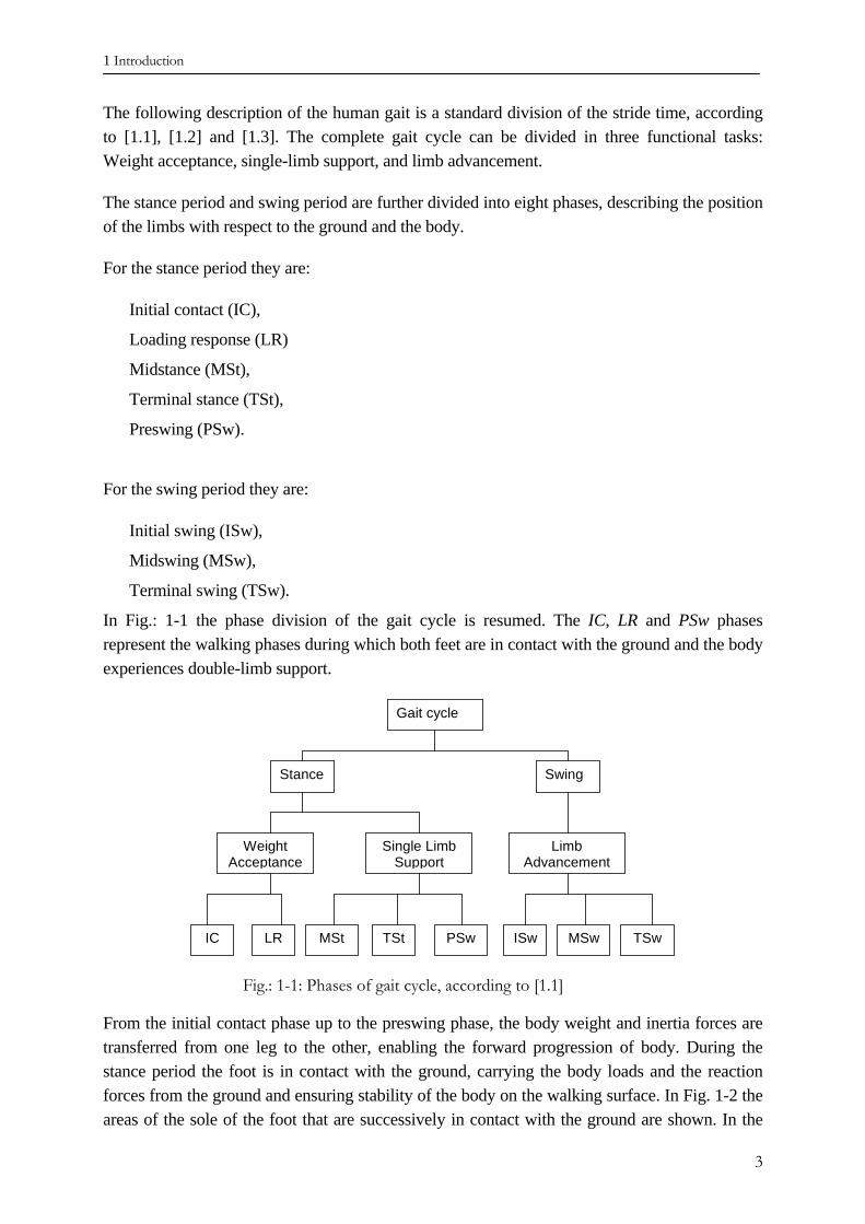
In Fig.: 1-1 the phase division of the gait cycle is resumed. The IC, LR and PSw phases represent the walking phases during which both feet are in contact with the ground and the body experiences double-limb support.
Gait cycle
Stance Swing
Weight Acceptance
Single Limb Support
Limb Advancement
IC LR ISwPSwTStMSt TSw MSw
Fig.: 1-1: Phases of gait cycle, according to [1.1]
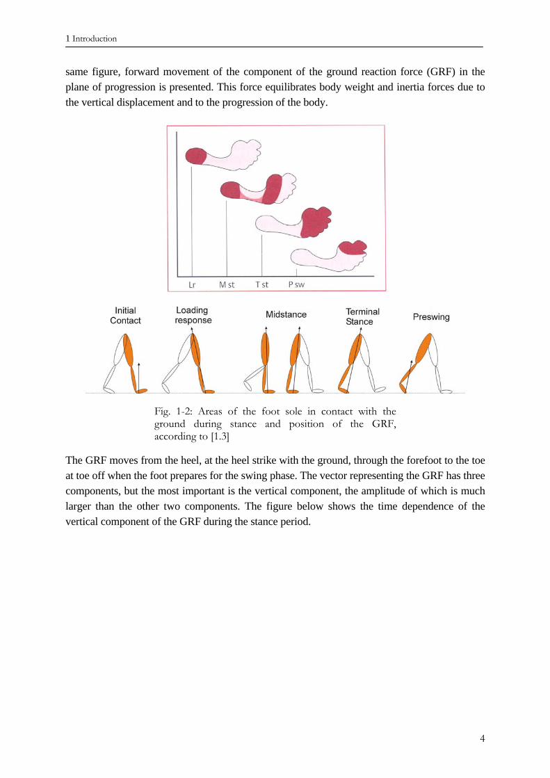
From the initial contact phase up to the preswing phase, the body weight and inertia forces are transferred from one leg to the other, enabling the forward progression of body. During the stance period the foot is in contact with the ground, carrying the body loads and the reaction forces from the ground and ensuring stability of the body on the walking surface. In Fig. 1-2 the areas of the sole of the foot that are successively in contact with the ground are shown. In the
3
1 Introduction
same figure, forward movement of the component of the ground reaction force (GRF) in the plane of progression is presented. This force equilibrates body weight and inertia forces due to the vertical displacement and to the progression of the body.
Fig. 1-2: Areas of the foot sole in contact with the ground during stance and position of the GRF, according to [1.3]
The GRF moves from the heel, at the heel strike with the ground, through the forefoot to the toe at toe off when the foot prepares for the swing phase. The vector representing the GRF has three components, but the most important is the vertical component, the amplitude of which is much larger than the other two components. The figure below shows the time dependence of the vertical component of the GRF during the stance period.
4
1 Introduction
0
20
40
60
80
100
120
140
0 10 20 30 40 50 60 70 80time - percentage of the time period of the stride
GR
F - p
erce
ntag
e of
the
body
wei
ght
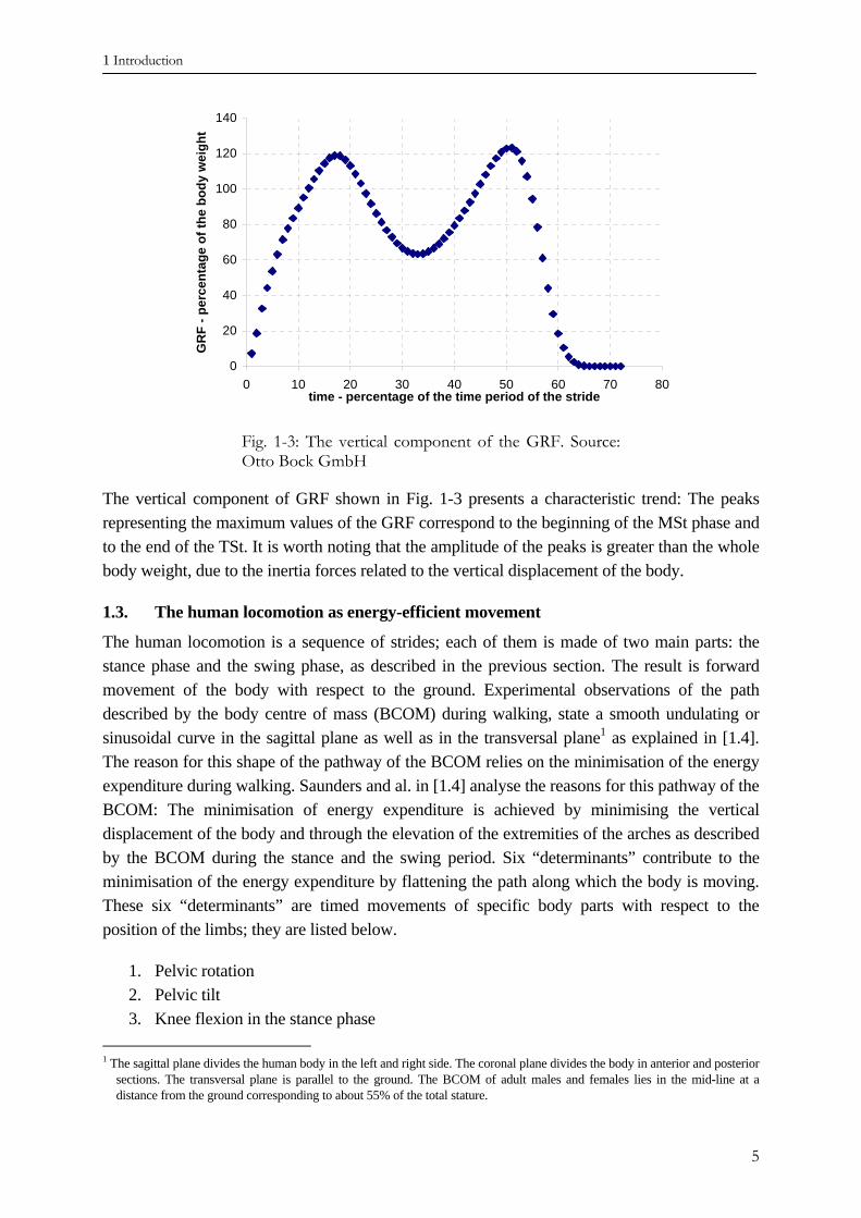
Fig. 1-3: The vertical component of the GRF. Source: Otto Bock GmbH
The vertical component of GRF shown in Fig. 1-3 presents a characteristic trend: The peaks representing the maximum values of the GRF correspond to the beginning of the MSt phase and to the end of the TSt. It is worth noting that the amplitude of the peaks is greater than the whole body weight, due to the inertia forces related to the vertical displacement of the body.
1.3. The human locomotion as energy-efficient movement
The human locomotion is a sequence of strides; each of them is made of two main parts: the stance phase and the swing phase, as described in the previous section. The result is forward movement of the body with respect to the ground. Experimental observations of the path described by the body centre of mass (BCOM) during walking, state a smooth undulating or sinusoidal curve in the sagittal plane as well as in the transversal plane1 as explained in [1.4]. The reason for this shape of the pathway of the BCOM relies on the minimisation of the energy expenditure during walking. Saunders and al. in [1.4] analyse the reasons for this pathway of the BCOM: The minimisation of energy expenditure is achieved by minimising the vertical displacement of the body and through the elevation of the extremities of the arches as described by the BCOM during the stance and the swing period. Six “determinants” contribute to the minimisation of the energy expenditure by flattening the path along which the body is moving. These six “determinants” are timed movements of specific body parts with respect to the position of the limbs; they are listed below.
1. Pelvic rotation 2. Pelvic tilt 3. Knee flexion in the stance phase
1 The sagittal plane divides the human body in the left and right side. The coronal plane divides the body in anterior and posterior
sections. The transversal plane is parallel to the ground. The BCOM of adult males and females lies in the mid-line at a distance from the ground corresponding to about 55% of the total stature.
5
1 Introduction
4. Foot mechanism 5. Knee mechanism 6. Lateral displacement of the pelvis
Pelvic rotation The pelvis can be considered a rigid body. At every step it rotates about a vertical axis shifting forward the hip joint of the swinging leg and flattening the extremities of the arcs described by the BCOM during walking.
Pelvic tilt When the BCOM moves over the bearing leg, it reaches maximum elevation. In this phase, the pelvis is being tilted down to the opposite side. The effect of this movement is to decrease the maximum elevation of the BCOM.
Knee flexion in the stance phase The knee flexion that occurs between the loading acceptance, up to the one-leg bearing phase (the bearing leg is vertical and the BCOM moves over it), determines a further decrease in the maximum elevation of the BCOM.
Foot mechanism and knee mechanism Both determinants are intimately correlated and occur when the BCOM has passed the bearing leg and this latter prepares for the swing phase. The combined action of both mechanisms contributes to smooth the lowest points of the arcs described by the BCOM, corresponding to the nadir of the pathway described by the BCOM.
Lateral displacement of the pelvis The lateral displacement of the pelvis contributes in reducing the overall lateral displacement of the BCOM in the transversal plane by narrowing the distance between the legs and the distance between the lines parallel to the line of progression representing the successive point of contact of the feet with the ground.
This analysis of human walking has now been accepted for more than fifty years and represents a classical approach to understanding human gait. Several authors validated this model with further studies and clinical research.
The authors, Gard and Childress in [1.5], state that pelvic tilt and knee flexion during the stance phase have little or no effect on the magnitude of the body’s vertical displacement due to the timing of both “determinants” with the trunk vertical excursion during normal gait. According to these authors, these determinants contribute to shock absorption during the loading response phase of gait.
Due to the absence of the normal limb, the trans-femoral amputees show a different gait pattern compared to normal locomotion. The asymmetry of the gait pattern between the sound limb and the artificial limb is a measure of the difficulties encountered by the patients.
6
1 Introduction
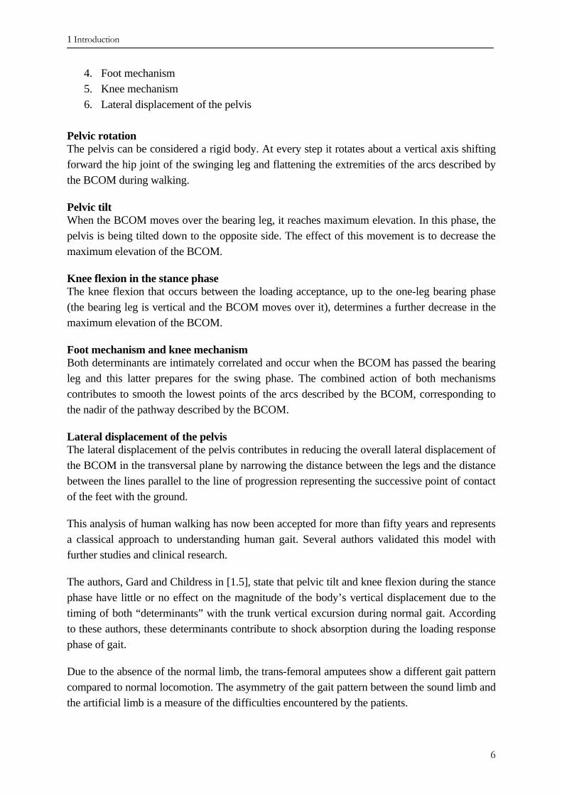
The energy expenditure of amputees during walking is higher, compared to that of non-amputees, at comparable walking velocities as described in [1.6], [1.7], [1.8], [1.9] and the level of the amputation exacerbates energy expenditure. The oxygen uptake value of the patient mirrors the energy expenditure during walking. In Fig. 1-4, the oxygen cost related to the amputation level and to the walking speed according to [1.12] is shown. The patient is not able to perform an optimal gait pattern, since the artificial limb does not allow some of the above determinants and this leads to increased energy expenditure. Furthermore, the patient is sometimes forced to make appropriate movements in order to control the motion of the prosthesis.
All possible deviations from an ideal path of the BCOM cause a higher expenditure of energy and less comfort for the patient.
Fig. 1-4: Energy expenditure according to [1.12]. TT: trans-tibial; TK: through-knee; TF: trans-femoral; HD: hip disarticulation; HP: hemi-pelvectomy. The oxygen cost is measured in millilitres O2 per kilogram weight per meter covered by the patient.
An appropriate geometric model can reproduce the experimental observation of the BCOM pathway during the stance period. The combined action performed by the sound limb and foot is taken into account through a rocker-based inverted pendulum as presented in [1.5]. Through this model, Gard and Childress in [1.5] have been able to predict the vertical displacement of the body during stance. The analytical results are in good agreement with the experimental results.
7
1 Introduction
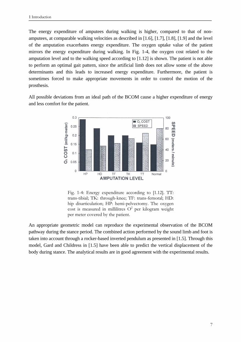
Fig. 1-5: The rocker-based inverted pendulum. “R” represents the radius of the rocker
Hansen, in [1.11] has analysed the roll-over shape to which the sound limb conforms during stance. The roll-over shape represents the trajectory followed by the centre of pressure of the foot on the ground during stance.
Considering the rocker model presented in [1.5] and shown in Fig. 1-5, the radius “R” determines the profile of the rocker. It is possible to establish an equivalence between the radius of the rocker and the roll-over shape. According to this equivalence, if the profile of the rocker conforms to the roll-over shape, the pathway of the BCOM of the rocker model copies that of the analysed patient.2 The calculation of the roll-over shape has been performed for several normal people under various conditions, such as different gait velocity, increased carried weight, different inclinations of the walking surface and varying shoe heel height. The results of this work clearly show that the roll-over shape of the human foot is invariant with respect to the walking speed and is not significantly affected by carrying different amounts of added weights. Furthermore, the orientation of the roll-over shape changes when walking on inclined surfaces.
These considerations show that the normal human foot is able to adjust its characteristic to different situations and to adapt its equivalent roll-over shape: The main purpose of this adaptation is to keep the body moving in an energetic efficient way. The normal human locomotion optimises the energy expenditure during walking by minimising the vertical displacement of the body and by smoothing the pathway described by the BCOM. Walking at higher velocity or carrying an added weight increase the whole energy of the gait, the kinetic energy as well as the potential energy. The body, through adaptation of the foot roll-over shape, reacts to these situations, seeking the optimal gait pattern.
1.4. The function of the prosthetic limb
Depending on the level of the amputation, the missing lower limb can be replaced with an artificial limb, or prosthetic leg, that restores the locomotive function and the normal appearance of the lost body part. The acceptance of this device depends on its functional requirements, such as load-carrying properties and correct dynamic behaviour, as well as on its comfort and appearance of normality that it is able to show. The artificial limb for a transfemoral amputee is 2 The determination of the radius “R” is performed considering the trajectory of centre of pressure of the sole of the foot with
respect to a reference system moving with the sound limb.
8
1 Introduction
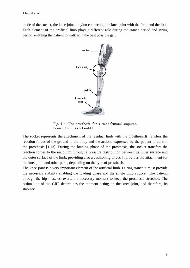
made of the socket, the knee joint, a pylon connecting the knee joint with the foot, and the foot. Each element of the artificial limb plays a different role during the stance period and swing period, enabling the patient to walk with the best possible gait.
knee joint
socket
Prostheticfoot
pylon
knee joint
socket
Prostheticfoot
pylon
knee joint
socket
Prostheticfoot
pylon
Fig. 1-6: The prosthesis for a trans-femoral amputee. Source: Otto Bock GmbH
The socket represents the attachment of the residual limb with the prosthesis.It transfers the reaction forces of the ground to the body and the actions expressed by the patient to control the prosthesis [1.13]. During the loading phase of the prosthesis, the socket transfers the reaction forces to the residuum through a pressure distribution between its inner surface and the outer surface of the limb, providing also a cushioning effect. It provides the attachment for the knee joint and other parts, depending on the type of prosthesis. The knee joint is a very important element of the artificial limb. During stance it must provide the necessary stability enabling the loading phase and the single limb support. The patient, through the hip muscles, exerts the necessary moment to keep the prosthesis stretched. The action line of the GRF determines the moment acting on the knee joint, and therefore, its stability.
9
1 Introduction
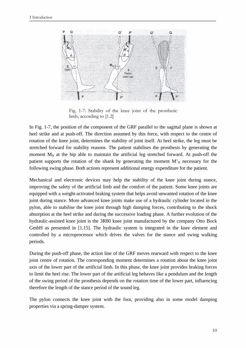
Fig. 1-7: Stability of the knee joint of the prosthetic limb, according to [1.2]
In Fig. 1-7, the position of the component of the GRF parallel to the sagittal plane is shown at heel strike and at push-off. The direction assumed by this force, with respect to the centre of rotation of the knee joint, determines the stability of joint itself. At heel strike, the leg must be stretched forward for stability reasons. The patient stabilises the prosthesis by generating the moment MH at the hip able to maintain the artificial leg stretched forward. At push-off the patient supports the rotation of the shank by generating the moment M’H necessary for the following swing phase. Both actions represent additional energy expenditure for the patient.
Mechanical and electronic devices may help the stability of the knee joint during stance, improving the safety of the artificial limb and the comfort of the patient. Some knee joints are equipped with a weight-activated braking system that helps avoid unwanted rotation of the knee joint during stance. More advanced knee joints make use of a hydraulic cylinder located in the pylon, able to stabilise the knee joint through high damping forces, contributing to the shock absorption at the heel strike and during the successive loading phase. A further evolution of the hydraulic-assisted knee joint is the 3R80 knee joint manufactured by the company Otto Bock GmbH as presented in [1.15]. The hydraulic system is integrated in the knee element and controlled by a microprocessor which drives the valves for the stance and swing walking periods.
During the push-off phase, the action line of the GRF moves rearward with respect to the knee joint centre of rotation. The corresponding moment determines a rotation about the knee joint axis of the lower part of the artificial limb. In this phase, the knee joint provides braking forces to limit the heel rise. The lower part of the artificial leg behaves like a pendulum and the length of the swing period of the prosthesis depends on the rotation time of the lower part, influencing therefore the length of the stance period of the sound leg.
The pylon connects the knee joint with the foot, providing also in some model damping properties via a spring-damper system.
10
1 Introduction
The main function of the foot is to transfer the reacting loads from the ground up to the socket and to the patient, to ensure the stability and safeness of the gait. The foot is normally connected with the shank through a joint, able to simulate in various ways the capabilities of the normal ankle joint. Depending on the design, it is not possible for some prosthetic feet to distinguish the ankle joint from the rest of the prosthetic foot, since the structure of the foot itself integrates the ankle joint and some of its properties.
At heel strike, the foot is provided with elastic elements able to absorb the shock of the impact and to cushion the forces encoutered. During the stance phase, the roll-over shape assumed by the foot should be smooth; the elasticity of the elements constituting the forefoot plays a key role in allowing a comfortable gait for the patient. At push-off, the ground reaction force reaches its second peak and the shank rotates. The foot should provide an appropriate dorsiflexion of the forefoot for a smooth rotation of the lower part of the prosthesis and provide a comfortable terminal stance phase of the gait. The ankle joint between foot and pylon provides at least a degree of freedom, enabling dorsiflexion and plantarflexion of the foot during stance. At heel strike, the GRF generates a plantarflexion moment which brings the foot in contact with the ground. At the midstance phase, the BCOM passes over the supporting foot and the GRF moves forward generating a dorsiflexion of the foot.
1.5. State of the art
Research on prosthetic components and, in particular, on prosthetic feet has produced many different foot designs. There are two main categories of prosthetic foot on the market: The conventional foot and the energy storing, or dynamic, foot. The designs of these two categories can be further divided into uni-axial and multi-axial feet, depending upon the rotational degree of freedom permitted by the ankle joint. Unlike the conventional type, the dynamic type is able to store potential energy through the deformation of the elastic elements of which it is made, reducing the kinetic energy in a spring-like manner. At heel rise and at push-off the potential energy is released, while the spring elements return to their original shape, helping to push the patient’s body forward. The advantage of this type of foot is a less energy expenditure by the patient at the same walking velocity.
The aim of each prosthetic foot is to mimic as much as possible the behaviour of the human foot. Rihs et al. in [1.17] has listed the characteristics considered important by the patient to achieve normal gait motion. These include:
• Dorsiflexion • Eversion • Impact Absorption • Energy Return • Ankle Torsion The evolution of the prosthetic feet aims to better replace the functions of the lost body part by designing components which simulate, to the extend possible, the function of the normal foot. In the group of conventional design is SACH (Solid Ankle Cushioning Heel) foot, which is
11
1 Introduction
preferred for comparing the performance of the prosthetic foot of the dynamic type. The evaluation of the prosthetic foot is based on several quantities, the cadence (number of steps per minute at a self selected gait velocity), step length, amplitude of the vertical component of the GRF, the ankle moment and, most importantly, the energy cost for the patient. The SACH foot has been the classical solution for foot replacement for more than 30 years. The choice of the type of foot depends on the level of the amputation, on the weight,, age and activity level of the patient. The advancement of the prosthetic foot has focused on the design of the foot and on the materials employed in manufacturing. The SACH foot produced by Otto Bock Health Care Company, for instance, is made of a flexible keel embedded in a polyurethane body with a bolt for connection to the pylon. The materials employed in manufacturing ranges from wood (poplar), synthetic foam to composite materials for new prosthetic feet. The latter belong primarily to the category of energy storing feet, for which the design and the material emphasise the elastic response of the foot and its ability to deform under the different load conditions.
In this category is the Flex–Foot manufactured by the Ossur Company, the Flex-Walk foot made by Flex-Foot Inc., the Springlite foot by Otto Bock, the Re-Flex VSP produced by the Ossur Company, the Pathfinder made by the Ohio Willow Wood company and many others. All these feet use a carbon fibre reinforced composite material for the parts constituting the foot and in some model the shank is also made of the same material. The bearing and flexible components are constituted of thin leaf springs bolted together (Flex-Walk and Flex-Foot) or joined by an elastomer (Springlite). The Re-Flex VSP is fitted with an adjustable pylon connected to a leaf spring for absorbing impact forces and the Pathfinder has a pneumatic heel spring for the same purpose.
Many studies have been conducted to assess and quantify properties and benefits of the newer prosthetic feet compared to the classic types. Macfarlane et al. in [1.7] has compared the SACH foot with the Flex-Foot and the latter has shown slightly better performances. Postema et al. in [1.16] were not able to determine a clinical relevance between two classic prosthetic feet and two dynamic feet regarding the mechanical energy expended bythe patient. Also Unterwood in [1.18] found better acceptance of the dynamic foot by the patient with respect to the classic type, but few biomechanical differences between the gait characteristics of the tested prosthetic feet have been found.
Regarding the possibility of actively changing the static response of the prosthetic foot to adapt its behaviour to different gait conditions and to the patient’s characteristics, only the work of R.J. Christensen described in [1.19] has been found. The concept is based on the possibility of controlling the flow of a fluid by adjusting its viscosity, like an electrorheologic or magnetorheologic fluid. Through the variation of the viscosity of the fluid it is possible to adjust the deformation of the leaf springs of the foot structure and therefore the response of the foot during the stance phase. Christensen proposed several prosthetic feet based on this concept.
In other prosthetic feet, the mechanical characteristics can be varied manually but this is not desirable. For instance, the Gold metal foot by Otto Bock offers the possibility to vary its heel characteristics with interchangeable rubber plugs. Changes in the prosthetic characteristics are
12
1 Introduction
possible in several products by adjusting on the screws connecting the elastic elements, as in [1.20] or tuning their relative position.
1.6. Objective of the project
In the previous chapter it has been seen that the human gait represents an optimised process able to minimise the energy expenditure during walking. The minimisation of the energy necessary for the movement is achieved through the timed and coordinated movements of selected body parts called “determinants”.
The stiffness characteristics of the prosthetic foot affect its structural response during stance. Since the load experienced by the foot changes its amplitude and its distribution during the stance phase period, every prosthetic foot represents a compromise to different optimal characteristics. The deformation of the foot contributes to the vertical displacement of the body during stance. It also contributes to the length of the stance period of the prosthetic limb and to the length of the swing period of the heealthy limb. Therefore the mechanical properties of the foot greatly influence the cinematic characteristics of the gait cycle and the comfort of the patient.
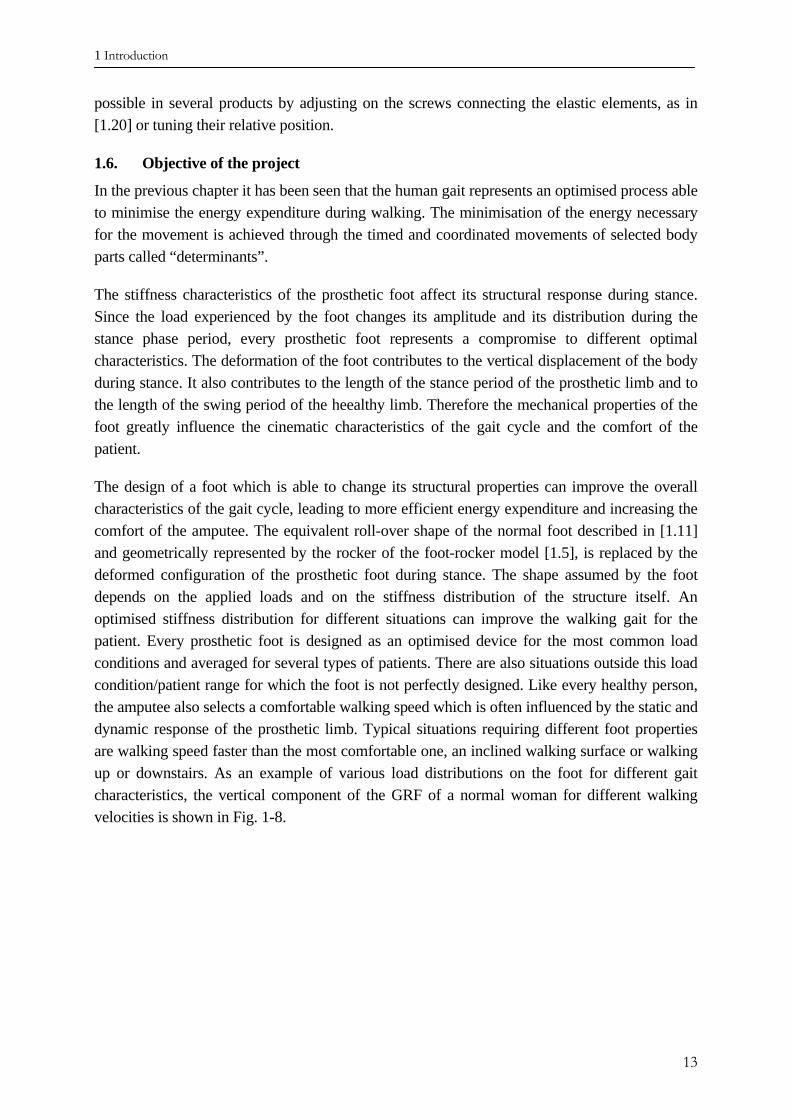
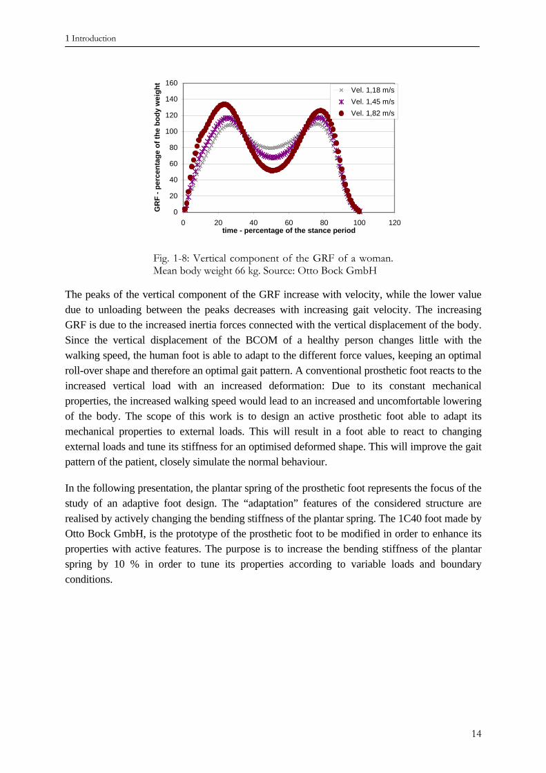
The design of a foot which is able to change its structural properties can improve the overall characteristics of the gait cycle, leading to more efficient energy expenditure and increasing the comfort of the amputee. The equivalent roll-over shape of the normal foot described in [1.11] and geometrically represented by the rocker of the foot-rocker model [1.5], is replaced by the deformed configuration of the prosthetic foot during stance. The shape assumed by the foot depends on the applied loads and on the stiffness distribution of the structure itself. An optimised stiffness distribution for different situations can improve the walking gait for the patient. Every prosthetic foot is designed as an optimised device for the most common load conditions and averaged for several types of patients. There are also situations outside this load condition/patient range for which the foot is not perfectly designed. Like every healthy person, the amputee also selects a comfortable walking speed which is often influenced by the static and dynamic response of the prosthetic limb. Typical situations requiring different foot properties are walking speed faster than the most comfortable one, an inclined walking surface or walking up or downstairs. As an example of various load distributions on the foot for different gait characteristics, the vertical component of the GRF of a normal woman for different walking velocities is shown in Fig. 1-8.
13
1 Introduction
0
20
40
60
80
100
120
140
160
0 20 40 60 80 100 120time - percentage of the stance period
GR
F - p
erce
ntag
e of
the
body
wei
ght
Vel. 1,18 m/sVel. 1,45 m/sVel. 1,82 m/s
Fig. 1-8: Vertical component of the GRF of a woman. Mean body weight 66 kg. Source: Otto Bock GmbH
The peaks of the vertical component of the GRF increase with velocity, while the lower value due to unloading between the peaks decreases with increasing gait velocity. The increasing GRF is due to the increased inertia forces connected with the vertical displacement of the body. Since the vertical displacement of the BCOM of a healthy person changes little with the walking speed, the human foot is able to adapt to the different force values, keeping an optimal roll-over shape and therefore an optimal gait pattern. A conventional prosthetic foot reacts to the increased vertical load with an increased deformation: Due to its constant mechanical properties, the increased walking speed would lead to an increased and uncomfortable lowering of the body. The scope of this work is to design an active prosthetic foot able to adapt its mechanical properties to external loads. This will result in a foot able to react to changing external loads and tune its stiffness for an optimised deformed shape. This will improve the gait pattern of the patient, closely simulate the normal behaviour.
In the following presentation, the plantar spring of the prosthetic foot represents the focus of the study of an adaptive foot design. The “adaptation” features of the considered structure are realised by actively changing the bending stiffness of the plantar spring. The 1C40 foot made by Otto Bock GmbH, is the prototype of the prosthetic foot to be modified in order to enhance its properties with active features. The purpose is to increase the bending stiffness of the plantar spring by 10 % in order to tune its properties according to variable loads and boundary conditions.
14
1 Introduction
REFERENCES CHAPTER I
[1.1] E. Ayyappa, “Normal Human Locomotion, Part 1: Basic Concepts and Terminology”, Journal
of Prosthetics and Orthotics, Vol. 9, No. 1, 1997.
[1.2] H. Dietl, R. Kaitan, R. Pawlik, P. Ferrara: „C-Leg – Ein neues System zur Versorgung von
Oberschenkelamputationen“, Orthopädie Technik 3/98.
[1.3] K. Götz-Neumann: „Gehen verstehen – Ganganalyse in der Physiotherapie“, Thieme Verlag,
2003.
[1.4] M. Saunders, V.T. Inman, H.D. Eberhart: “The Major Determinants in Normal and
Pathological Gait”, The Journal of Bone and Joint Surgery, 35-A, No. 3, 1953.
[1.5] S.A. Gard, D.S. Childress: “What Determines the Vertical Displacement of the Body during
Normal Walking?”, Journal of Prosthetics and Orthotics, Vol. 13, No. 3, 2001.
[1.6] D.H. Nielsen, D.G. Shurr, J.C. Golden, K. Meier: „Comparison of Energy Cost and Gait
Efficiency During Ambulation in Below-Knee Amputees Using Different Prosthetic Feet – A
Preliminary Report“, Journal of Prosthetics and Orthotics, Vol. 1, No. 1, 1989.
[1.7] P.A. Macfarlane, D.H. Nielson, D.G. Shurr: “Mechanical Gait Analysis of Transfemoral
Amputees: SACH Foot versus the Flex-Foot”, Journal of Prosthetics and Orthotics, Vol. 9, No.
4, 1997.
[1.8] B. Pflanz: “Entwicklung von Simulationsmodellen zur konstruktiven Optimierung von
Stoßdämpfersystemen an Beinprothesen“, Hausarbeit im Rahmen der ersten Staatsprüfung für
das Lehramt an Gymnasien, 2001.
[1.9] D.G. Barth, L. Schumacher, S. Sienko Thomas: “Gait Analysis and Energy Cost of Below-Knee
Amputees Wearing Six Different Prosthetic Feet”, Journal of Prosthetics and Orthotics, Vol. 4,
No. 2, 1992.
[1.10] P.A. Macfarlane, D.H. Nielson, D.G. Shurr, K.G. Meier, R. Clark, J. Kerns, M. Moreno, B.
Ryan: “Transfemoral Amputees Physiological Requirements: Comparison Between SACH Foot
Walking and Flex-Foot Walking”, Journal of Prosthetics and Orthotics, Vol. 9, No. 4, 1997.
[1.11] A. H. Hansen: “Roll-over Characteristics of Human Walking With Applications for Artificial
Limbs”, Ph.D. Dissertation, Northwestern University, 2002.
[1.12] R.L. Waters, S. Mulroy: “The energy expenditure of normal and pathological gait”, Gait and
Posture, 9 – 1999.
[1.13] A.F.-T. Mak, M. Zhang, A.K.-L. Leung: “Artificial Limbs”, in “Comprehensive Structural
Integrity”, Vol.9, edited by I. Milne, R.O. Ritchie, B. Karihaloo, Elsevier, 2003.
15
1 Introduction
[1.14] G.J. Verkerke, A.L. Hof, W. Zijstra, W. Ament, G. Rakhorst: „Determining the centre of
pressure during walking and running using an instrumented treadmill”, Journal of
Biomechanics, 38 (2005), 1881 – 1885.
[1.15] S. Blumentritt, H.W. Scherer, J.W. Michael, T. Schmalz: „Transfemoral Amputees Walking on a
Rotary Hydraulic Prosthetic Knee Mechanism: A Preliminary report”, Journal of Prosthetics
and Orthotics, Vol. 10, No. 3, 1998
[1.16] K. Postema, H.J. Hermens, J. De Vries, H.F. Koopman, W.H. Eisma: „Energy storage and
release of prosthetic feet. Part 1: Biomechanical Analysis related to user benefits”, Prosthetics
and Orthotics International, 1997, Apr. 21 (1), 17-27.
[1.17] D. Rihs, I. Polizzi: „Prosthetic foot Design”, Victorian University of Technology, Australia,
2001.
[1.18] H.A. Unterwood, C.D. Tokuno, J.J. Eng: “A comparison of two prosthetic feet on the multi-
joint and multi-plane kinetic gait compensations in individuals with a unilateral trans-tibial
amputation”, Clinical Biomechganics, 19, 2004.
[1.19] R.J. Christensen: “Prosthetic foot with energy transfer fluid including variable viscosity fluid”,
US Patent number 6663673.
[1.20] H. Graham: “Adaptable prosthetic foot”, European patent application no. 1 149 568 A1.
16
2 The reference model
17
2. The reference model
2.1. Description and analysis of the available foot
While the human foot is able to perform the necessary movements in order to assume the optimised rocker shape, a prosthetic foot under the influence of the ground reaction forces deforms as its elastic properties allow. The assumed shape is not always the most comfortable for the patient, and since the prosthetic foot is made of passive elements, the deformed shape is not tuneable.
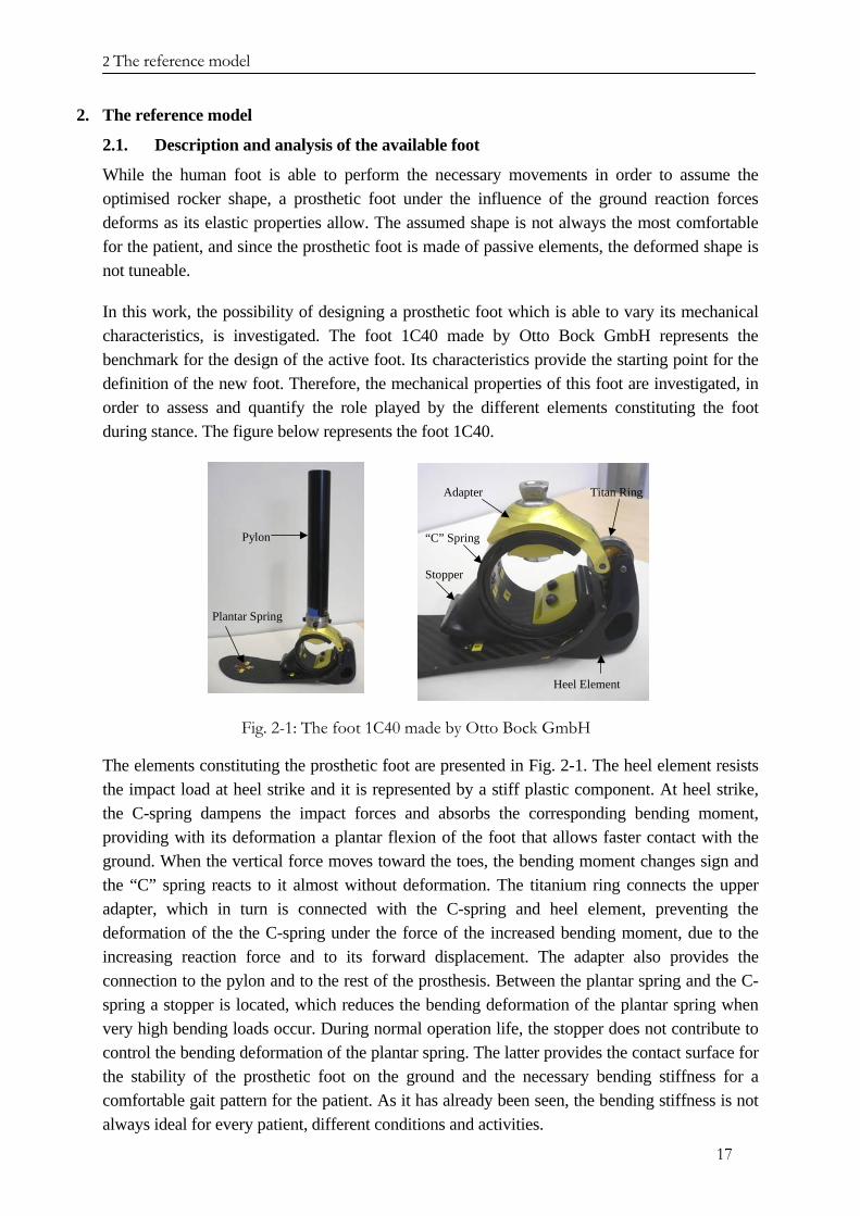
In this work, the possibility of designing a prosthetic foot which is able to vary its mechanical characteristics, is investigated. The foot 1C40 made by Otto Bock GmbH represents the benchmark for the design of the active foot. Its characteristics provide the starting point for the definition of the new foot. Therefore, the mechanical properties of this foot are investigated, in order to assess and quantify the role played by the different elements constituting the foot during stance. The figure below represents the foot 1C40.
Plantar Spring
Pylon
Adapter
“C” Spring
Heel Element
Titan Ring
Stopper
Fig. 2-1: The foot 1C40 made by Otto Bock GmbH
The elements constituting the prosthetic foot are presented in Fig. 2-1. The heel element resists the impact load at heel strike and it is represented by a stiff plastic component. At heel strike, the C-spring dampens the impact forces and absorbs the corresponding bending moment, providing with its deformation a plantar flexion of the foot that allows faster contact with the ground. When the vertical force moves toward the toes, the bending moment changes sign and the “C” spring reacts to it almost without deformation. The titanium ring connects the upper adapter, which in turn is connected with the C-spring and heel element, preventing the deformation of the the C-spring under the force of the increased bending moment, due to the increasing reaction force and to its forward displacement. The adapter also provides the connection to the pylon and to the rest of the prosthesis. Between the plantar spring and the C-spring a stopper is located, which reduces the bending deformation of the plantar spring when very high bending loads occur. During normal operation life, the stopper does not contribute to control the bending deformation of the plantar spring. The latter provides the contact surface for the stability of the prosthetic foot on the ground and the necessary bending stiffness for a comfortable gait pattern for the patient. As it has already been seen, the bending stiffness is not always ideal for every patient, different conditions and activities.
2 The reference model
18
The main deformable parts of the foot are represented by the C-spring and by the plantar spring. They deform under the reaction forces expressed by the ground, store the kinetic energy as potential energy and return it at heel rise and during the unloading phase, contributing to push-off. In this way, the patient limits the movement of the trunk necessary for the swing phase of the lower part of the prosthesis, resulting in lower energy expenditure. The 1C40 foot belongs to the category of the dynamic feet designed for storing energy and able to deform elastically.
2.2. Definition of the load condition acting on the foot during stance
The layout of the new prosthetic foot will be designed using the force distribution acting on the healthy foot as the design load parameters. In order to analyse the mechanical behaviour and the performance of the foot, it is necessary to select the load conditions which are most representative of the real environment experienced by the prosthetic foot. During the stance phase, the foot experiences a time variable load distribution. The ground reaction force presents three force components, but the vertical component represents the most important contribution to the load acting on the foot.
-40
-20
0
20
40
60
80
100
120
140
160
0 10 20 30 40 50 60 70 80 90 100 110
Time - Percentage of the period of the stance phase
GR
F - P
erce
ntag
e of
the
body
wei
ght,
Mom
ent [
m]
FIR
ST L
OA
D C
ON
DIT
ION
SEC
ON
D L
OA
D C
ON
DIT
ION
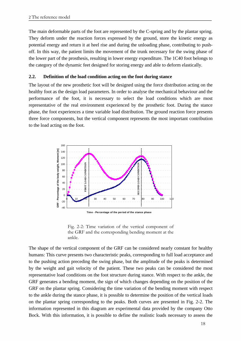
Fig. 2-2: Time variation of the vertical component of the GRF and the corresponding bending moment at the ankle.
The shape of the vertical component of the GRF can be considered nearly constant for healthy humans: This curve presents two characteristic peaks, corresponding to full load acceptance and to the pushing action preceding the swing phase, but the amplitude of the peaks is determined by the weight and gait velocity of the patient. These two peaks can be considered the most representative load conditions on the foot structure during stance. With respect to the ankle, the GRF generates a bending moment, the sign of which changes depending on the position of the GRF on the plantar spring. Considering the time variation of the bending moment with respect to the ankle during the stance phase, it is possible to determine the position of the vertical loads on the plantar spring corresponding to the peaks. Both curves are presented in Fig. 2-2. The information represented in this diagram are experimental data provided by the company Otto Bock. With this information, it is possible to define the realistic loads necessary to assess the
2 The reference model
19
static response of the available prosthetic foot, by means of a finite element simulation of the structure and of the boundary conditions.
The load condition corresponding to the first peak is represented by a vertical force located below the centre of the C-spring and corresponding to bending moment of zero. This can be easily assessed, correlating the ankle moment and the vertical force.
The second load condition corresponds to the maximum bending moment which is located approximately 150 mm from the position of the force corresponding to the first peak. For both peaks the amplitude has been set at 900 N, according to the experimental data.
2.3. Definition of the finite element model and numerical results
Unlike the real prosthetic foot, the foot implemented in the numerical model uses a symmetrical plantar spring. According to selected load conditions, not all the elements constituting the foot have been represented in the finite element model, since their contribution to the elasticity of the foot is negligible. The C-spring is made of two concentric C-shaped rings connected together in order to reduce the overall maximum strain. While the geometry of the C-springs and of the plantar spring are known, the properties of the material of which these two elements are made of, have not been provided. Both elastic elements are made of a carbon fibre reinforced composite material. Both elements constituting the C-spring have a constant thickness, while the plantar spring has a variable thickness along the X axis of the prosthetic foot, the distribution of which has been provided.
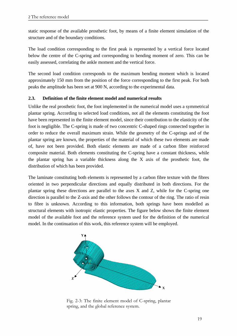
The laminate constituting both elements is represented by a carbon fibre texture with the fibres oriented in two perpendicular directions and equally distributed in both directions. For the plantar spring these directions are parallel to the axes X and Z, while for the C-spring one direction is parallel to the Z-axis and the other follows the contour of the ring. The ratio of resin to fibre is unknown. According to this information, both springs have been modelled as structural elements with isotropic elastic properties. The figure below shows the finite element model of the available foot and the reference system used for the definition of the numerical model. In the continuation of this work, this reference system will be employed.
X
Y
Z
Fig. 2-3: The finite element model of C-spring, plantar spring, and the global reference system.
2 The reference model
20
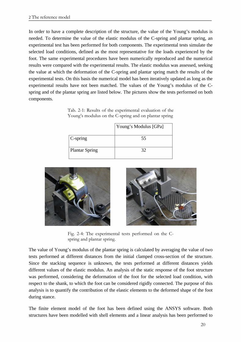
In order to have a complete description of the structure, the value of the Young’s modulus is needed. To determine the value of the elastic modulus of the C-spring and plantar spring, an experimental test has been performed for both components. The experimental tests simulate the selected load conditions, defined as the most representative for the loads experienced by the foot. The same experimental procedures have been numerically reproduced and the numerical results were compared with the experimental results. The elastic modulus was assessed, seeking the value at which the deformation of the C-spring and plantar spring match the results of the experimental tests. On this basis the numerical model has been iteratively updated as long as the experimental results have not been matched. The values of the Young’s modulus of the C-spring and of the plantar spring are listed below. The pictures show the tests performed on both components.
Tab. 2-1: Results of the experimental evaluation of the Young’s modulus on the C-spring and on plantar spring
Young’s Modulus [GPa]
C-spring 55
Plantar Spring 32
Fig. 2-4: The experimental tests performed on the C-spring and plantar spring.
The value of Young’s modulus of the plantar spring is calculated by averaging the value of two tests performed at different distances from the initial clamped cross-section of the structure. Since the stacking sequence is unknown, the tests performed at different distances yields different values of the elastic modulus. An analysis of the static response of the foot structure was performed, considering the deformation of the foot for the selected load condition, with respect to the shank, to which the foot can be considered rigidly connected. The purpose of this analysis is to quantify the contribution of the elastic elements to the deformed shape of the foot during stance.
The finite element model of the foot has been defined using the ANSYS software. Both structures have been modelled with shell elements and a linear analysis has been performed to
2 The reference model
21
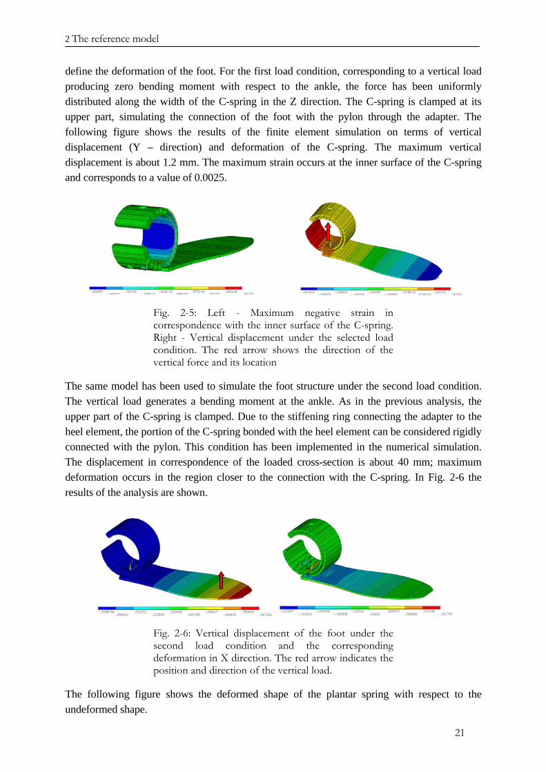
define the deformation of the foot. For the first load condition, corresponding to a vertical load producing zero bending moment with respect to the ankle, the force has been uniformly distributed along the width of the C-spring in the Z direction. The C-spring is clamped at its upper part, simulating the connection of the foot with the pylon through the adapter. The following figure shows the results of the finite element simulation on terms of vertical displacement (Y – direction) and deformation of the C-spring. The maximum vertical displacement is about 1.2 mm. The maximum strain occurs at the inner surface of the C-spring and corresponds to a value of 0.0025.
Fig. 2-5: Left - Maximum negative strain in correspondence with the inner surface of the C-spring. Right - Vertical displacement under the selected load condition. The red arrow shows the direction of the vertical force and its location
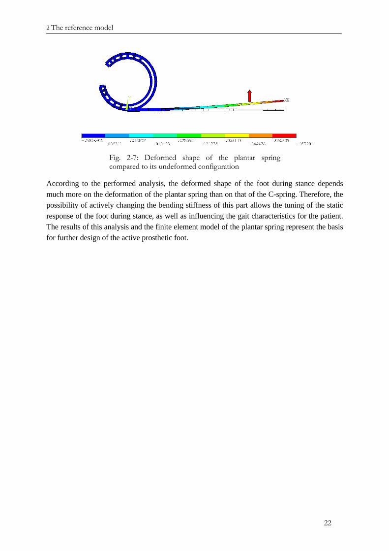
The same model has been used to simulate the foot structure under the second load condition. The vertical load generates a bending moment at the ankle. As in the previous analysis, the upper part of the C-spring is clamped. Due to the stiffening ring connecting the adapter to the heel element, the portion of the C-spring bonded with the heel element can be considered rigidly connected with the pylon. This condition has been implemented in the numerical simulation. The displacement in correspondence of the loaded cross-section is about 40 mm; maximum deformation occurs in the region closer to the connection with the C-spring. In Fig. 2-6 the results of the analysis are shown.
Fig. 2-6: Vertical displacement of the foot under the second load condition and the corresponding deformation in X direction. The red arrow indicates the position and direction of the vertical load.
The following figure shows the deformed shape of the plantar spring with respect to the undeformed shape.
2 The reference model
22
Fig. 2-7: Deformed shape of the plantar spring compared to its undeformed configuration
According to the performed analysis, the deformed shape of the foot during stance depends much more on the deformation of the plantar spring than on that of the C-spring. Therefore, the possibility of actively changing the bending stiffness of this part allows the tuning of the static response of the foot during stance, as well as influencing the gait characteristics for the patient. The results of this analysis and the finite element model of the plantar spring represent the basis for further design of the active prosthetic foot.
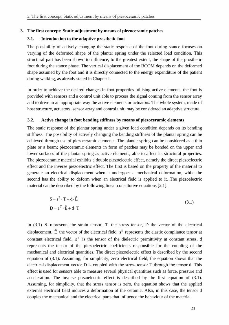
3. The first concept: Static adjustment by means of piezoceramic patches
23
3. The first concept: Static adjustment by means of piezoceramic patches
3.1. Introduction to the adaptive prosthetic foot
The possibility of actively changing the static response of the foot during stance focuses on varying of the deformed shape of the plantar spring under the selected load condition. This structural part has been shown to influence, to the greatest extent, the shape of the prosthetic foot during the stance phase. The vertical displacement of the BCOM depends on the deformed shape assumed by the foot and it is directly connected to the energy expenditure of the patient during walking, as already stated in Chapter I.
In order to achieve the desired changes in foot properties utilising active elements, the foot is provided with sensors and a control unit able to process the signal coming from the sensor array and to drive in an appropriate way the active elements or actuators. The whole system, made of host structure, actuators, sensor array and control unit, may be considered an adaptive structure.
3.2. Active change in foot bending stiffness by means of piezoceramic elements
The static response of the plantar spring under a given load condition depends on its bending stiffness. The possibility of actively changing the bending stiffness of the plantar spring can be achieved through use of piezoceramic elements. The plantar spring can be considered as a thin plate or a beam; piezoceramic elements in form of patches may be bonded on the upper and lower surfaces of the plantar spring as active elements, able to affect its structural properties. The piezoceramic material exhibits a double piezoelectric effect, namely the direct piezoelectric effect and the inverse piezoelectric effect. The first is based on the property of the material to generate an electrical displacement when it undergoes a mechanical deformation, while the second has the ability to deform when an electrical field is applied to it. The piezoelectric material can be described by the following linear constitutive equations [2.1]:
E
T
S s T d E
D E d
= ⋅ + ⋅
= ε ⋅ + ⋅
%
% T (3.1)
In (3.1) S represents the strain tensor, the stress tensor, D the vector of the electrical displacement, the vector of the electrical field. represents the elastic compliance tensor at constant electrical field, is the tensor of the dielectric permittivity at constant stress, d represents the tensor of the piezoelectric coefficients responsible for the coupling of the mechanical and electrical quantities. The direct piezoelectric effect is described by the second equation of (3.1): Assuming, for simplicity, zero electrical field, the equation shows that the electrical displacement vector D is coupled with the stress tensor T through the tensor d. This effect is used for sensors able to measure several physical quantities such as force, pressure and acceleration. The inverse piezoelectric effect is described by the first equation of (3.1). Assuming, for simplicity, that the stress tensor is zero, the equation shows that the applied external electrical field induces a deformation of the ceramic. Also, in this case, the tensor d couples the mechanical and the electrical parts that influence the behaviour of the material.
TE% Es
Tε
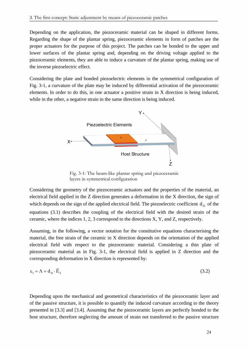
3. The first concept: Static adjustment by means of piezoceramic patches
24
Depending on the application, the piezoceramic material can be shaped in different forms. Regarding the shape of the plantar spring, piezoceramic elements in form of patches are the proper actuators for the purpose of this project. The patches can be bonded to the upper and lower surfaces of the plantar spring and, depending on the driving voltage applied to the piezoceramic elements, they are able to induce a curvature of the plantar spring, making use of the inverse piezoelectric effect.
Considering the plate and bonded piezoelectric elements in the symmetrical configuration of Fig. 3-1, a curvature of the plate may be induced by differential activation of the piezoceramic elements. In order to do this, in one actuator a positive strain in X direction is being induced, while in the other, a negative strain in the same direction is being induced.
Fig. 3-1: The beam-like plantar spring and piezoceramic layers in symmetrical configuration
Considering the geometry of the piezoceramic actuators and the properties of the material, an electrical field applied in the Z direction generates a deformation in the X direction, the sign of which depends on the sign of the applied electrical field. The piezoelectric coefficient of the
equations (3.1) describes the coupling of the electrical field with the desired strain of the ceramic, where the indices 1, 2, 3 correspond to the directions X, Y, and Z, respectively.
31d
Assuming, in the following, a vector notation for the constitutive equations characterising the material, the free strain of the ceramic in X direction depends on the orientation of the applied electrical field with respect to the piezoceramic material. Considering a thin plate of piezoceramic material as in Fig. 3-1, the electrical field is applied in Z direction and the corresponding deformation in X direction is represented by:
1 31d Eε = Λ = ⋅ % 3 (3.2)
Depending upon the mechanical and geometrical characteristics of the piezoceramic layer and of the passive structure, it is possible to quantify the induced curvature according to the theory presented in [3.3] and [3.4]. Assuming that the piezoceramic layers are perfectly bonded to the host structure, therefore neglecting the amount of strain not transferred to the passive structure
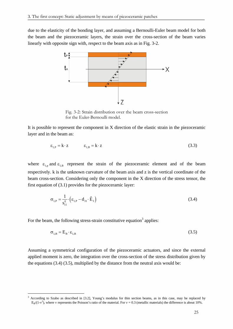
3. The first concept: Static adjustment by means of piezoceramic patches
25
due to the elasticity of the bonding layer, and assuming a Bernoulli-Euler beam model for both the beam and the piezoceramic layers, the strain over the cross-section of the beam varies linearly with opposite sign with, respect to the beam axis as in Fig. 3-2.
Fig. 3-2: Strain distribution over the beam cross-section for the Euler-Bernoulli model.
It is possible to represent the component in X direction of the elastic strain in the piezoceramic layer and in the beam as:
1,P 1,Bk z k zε = ⋅ ε = ⋅ (3.3)
where represent the strain of the piezoceramic element and of the beam
respectively. k is the unknown curvature of the beam axis and z is the vertical coordinate of the beam cross-section. Considering only the component in the X direction of the stress tensor, the first equation of (3.1) provides for the piezoceramic layer:
1,p 1,Bandε ε
(1,P 1,P 31 3E11
1 d Es
σ = ⋅ ε − ⋅ % )
(3.4)
For the beam, the following stress-strain constitutive equation3 applies:
1,B B 1,BEσ = ⋅ε (3.5)
Assuming a symmetrical configuration of the piezoceramic actuators, and since the external applied moment is zero, the integration over the cross-section of the stress distribution given by the equations (3.4) (3.5), multiplied by the distance from the neutral axis would be:
3 According to Szabo as described in [3.2], Young’s modulus for thin section beams, as in this case, may be replaced by
EB/(1-ν2), where ν represents the Poisson’s ratio of the material. For ν = 0.3 (metallic materials) the difference is about 10%.
3. The first concept: Static adjustment by means of piezoceramic patches
26
B BP
B
t t t2 2
1,B 1,Pt02
z dz z dz 0+
σ ⋅ ⋅ + σ ⋅ ⋅ =∫ ∫ (3.6)
Substituting in (3.6) the equations (3.3), (3.4) and (3.5), it is possible to determine the curvature of the beam induced by the active piezoceramic layers:
( )B
B 2
1 26 1T t
k 12 86T T
⎛ ⎞⎛ ⎞⋅ + ⋅⎜ ⎟⎜ ⎟⎝ ⎠ ⎝ ⎠=
+ Ψ + +⋅ Λ (3.7)
In the equation (3.7), T and are calculated by: BΨ
BB
P P
t ETt E
⋅= Ψ =
⋅B B
P
tt
P
P
(3.8)
Bt and t represent the thickness of the beam and the piezoceramic layers, respectively,
the Young’s modulus of the beam and the piezoceramic material respectively. Λ corresponds to the quantity expressed in the equation (3.2).
BE and E
The induced curvature given by (3.7), influences the shape of the of the beam axis. Assuming a linear behaviour for the beam, the bonded piezoceramic elements are able to modify the deformed shape of the beam, generated by the external loads. Since the plantar spring is like a cantilevered thin cross-section beam, it is then possible to modify the static response of the structure, under the selected load condition, by activating the piezoelectric actuators bonded to both upper and lower surfaces. The piezoceramic layers can be driven in order to partially compensate the deformation due to the GRF. The activation of the piezoceramic results in an increased bending stiffness of the plantar spring.
To quantify the change in bending stiffness, it is necessary to define a measure of its variation. Considering the ratio between the load F applied at the point in Z direction and the vertical displacement of the beam axis due to this load at the arbitrary point , it is possible to define
the following quantity:
ix
jx
iij
j
F(x )Kw(x )
= (3.9)
3. The first concept: Static adjustment by means of piezoceramic patches
27
where can be regarded as the stiffness at the point corresponding to a force applied in
. The activation of the piezoceramic elements induces a curvature of the beam axis, modifying the static response of the structure. Considering the load condition selected as representative of the load distribution during the stance phase, the displacement of the beam, due to the bending load, is varied by the piezoelectric elements. It is possible to define the same quantity , defined in (3.9) for the displaced axis of the beam due to the concentrated bending
load, considering the piezoelectric patches as passive elements and when they are activated.
ijK jx
ix
ijK
The change in bending stiffness is defined by comparing the quantities:
0 Piij ij0
j j
F(x ) F(x )K Kw (x ) w (x )
= = iP (3.10)
where the indices 0 and P denote the vertical displacement at the location when the
piezoceramic elements are passive, and when activated, respectively. jx
Considering the static response of the cantilever beam determined by the active layers, the effect of the piezoceramic actuators in a symmetrical configuration is maximised when they cover the whole length of the beam. Assuming the cantilevered beam is loaded by the bending force F acting on the beam’s free end and by the piezoceramic actuators extending over its whole length, the vertical displacement of points of the beam axis, at distance x from the clamped cross-section, is represented by:
P0
3 2T
ww
F FL 1w (x) x x k x6B 2B 2
= ⋅ − ⋅ + ⋅ ⋅ 2
142431442443 (3.11)
In (3.11), k represents the curvature induced by the piezoelectric actuators, while B represents the constant bending stiffness of the beam cross-section given by:
23 3B pB B P
P P
t tE t a tB a 2 E t a12 12 2
⎡ ⎤+⎛ ⎞⋅ ⋅⎢= ⋅ + ⋅ ⋅ + ⋅ ⋅⎜ ⎟⎢ ⎥⎝ ⎠⎣ ⎦
⎥ (3.12)
In the above expression, the contribution of the piezoceramic layers to the bending stiffness is taken into account. and in (3.11) represent the vertical displacement of the beam axis
due to the bending force F and to the action of the piezoceramic actuators, respectively. Since the load condition has been defined, the point of application of the vertical bending load is assigned. In order to quantify the change in bending stiffness of the beam, it is necessary to define the point upon which the vertical displacement is being measured. For this purpose, the same point where the bending load is applied has been selected for assessing the values of the
0w Pw
ix
3. The first concept: Static adjustment by means of piezoceramic patches
28
function (3.9). The change in the static response of the beam at that location may be expressed as:
P 0P 0
0
0
1 1w wK KK 100 1001K
w
−−
∆ = ⋅ = ⋅ (3.13)
The change in the value of K mirrors the change in the bending stiffness B of the beam.
Considering the expression of the vertical displacement w(x) of the beam axis given by (3.11), it is possible to derive the component of the elastic strain in the X direction4:
( )2
2
w F(x) z x L k zx B
∂ ⎡ε = − ⋅ = − ⋅ − + ⋅⎢∂ ⎣ ⎦⎤⎥ (3.14)
The maximum strain occurs in the corresponding outer fibres of the beam cross-section, located
at distance BP
tz2
⎛= ± +⎜⎝ ⎠
t ⎞⎟
from the beam axis. The value of the strain is an important
parameter to consider in the design of the plantar spring with solid-state actuators, since the piezoceramic material is quite brittle compared to the composite material of which the foot element is constructued. The bending deformation due to force F may result in a high deformation value high enough to damage the piezoceramic material.
3.3. Numerical results of the proposed concept
Through a finite element model, the change in bending stiffness in plantar spring with piezoceramic actuators can be quantified. The same numerical model already presented in the second chapter has been updated, in order to take the active layers into account. Since the piezoceramic layer is an induced strain actuator, an equivalent thermal model has been employed in order to simulate the effects of the solid-state actuators. Considering the
piezoelectric effect, for which the E-field is applied in a direction perpendicular to the plane of the piezoceramic element, the strain Λ
31d
PZT performed by the piezoceramic material can be replaced by a thermal strain, as the following equation shows:
PZT T 31 3 Pd E TΛ = Λ ⇒ ⋅ = α ⋅∆ (3.15)
In the expression (3.15) αP, ∆T and E3 represent the thermal expansion coefficient of the material constituting the piezoceramic elements, the temperature difference and the applied
4 The partial derivative symbol is being used in (3.14) since the applied voltage can be regarded as an independent variable.
3. The first concept: Static adjustment by means of piezoceramic patches
29
electrical field, respectively. It is possible to relate the temperature difference to the applied electrical voltage through the equation:
31 3P
1d E T⋅ ⋅ = ∆α
(3.16)
The quantities d31, tP and αP are known.
The active plantar spring has been implemented in the numerical model with shell elements, the properties of which have been defined, in order to take into account both the passive structure and the active layers, represented by the piezoceramic elements. ANSYS software has been used in defining the finite element model of the plantar spring. The thickness distribution of the passive structure corresponds to the given data, while the thickness of the active layer has been kept constant along the X-axis of the beam.
Extending the consideration presented above to the case of non-uniform bending stiffness distribution of the passive structure, it is possible to simulate the active change in bending stiffness acting on design parameters . P Pt , U,d,E
Two different types of piezoceramic material have been considered. The first one, provided by Smart Materials GmbH is represented by a low stiffness ceramic, which allows a larger positive strain than the other category. The advantage of these piezoceramic patches is that the desired strain in the X direction is achieved by making use of the piezoelectric effect instead of the
more common effect. The value of is usually larger than that of and therefore this
kind of material performs larger strains. Unlike the other type of active material, these elements are constructed with all fibres oriented in the same direction (X direction of Fig. 2-2) and embedded together with the electrodes in an epoxy matrix. The electrodes are perpendicular to the direction of the fibres in order to generate the appropriate electrical field in the same direction as the fibres. The second type is characterised by a higher Young’s modulus but a lower maximum positive admissible strain and is provided by Physik Instrumente (PI) GmbH. These patches use the more common effect for the desired strain in X direction. In order to
compare the change in bending stiffness occurring when the piezoceramic actuators are activated, the thickness of the plate made of the stiffer ceramic has been adjusted. In this way, both configurations present the same bending stiffness.
33d
31d 33d 31d
31d
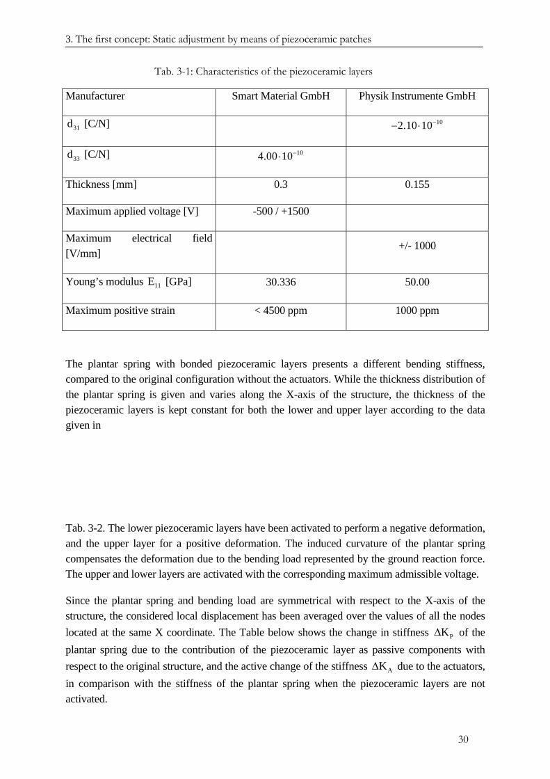
3. The first concept: Static adjustment by means of piezoceramic patches
30
Tab. 3-1: Characteristics of the piezoceramic layers
Manufacturer Smart Material GmbH Physik Instrumente GmbH
31d [C/N] 102.10 10−− ⋅
33d [C/N] 104.00 10−⋅
Thickness [mm] 0.3 0.155
Maximum applied voltage [V] -500 / +1500
Maximum electrical field [V/mm]
+/- 1000
Young’s modulus [GPa] 11E 30.336 50.00
Maximum positive strain < 4500 ppm 1000 ppm
The plantar spring with bonded piezoceramic layers presents a different bending stiffness, compared to the original configuration without the actuators. While the thickness distribution of the plantar spring is given and varies along the X-axis of the structure, the thickness of the piezoceramic layers is kept constant for both the lower and upper layer according to the data given in
Tab. 3-2. The lower piezoceramic layers have been activated to perform a negative deformation, and the upper layer for a positive deformation. The induced curvature of the plantar spring compensates the deformation due to the bending load represented by the ground reaction force. The upper and lower layers are activated with the corresponding maximum admissible voltage.
Since the plantar spring and bending load are symmetrical with respect to the X-axis of the structure, the considered local displacement has been averaged over the values of all the nodes located at the same X coordinate. The Table below shows the change in stiffness of the plantar spring due to the contribution of the piezoceramic layer as passive components with respect to the original structure, and the active change of the stiffness
PK∆
AK∆ due to the actuators, in comparison with the stiffness of the plantar spring when the piezoceramic layers are not activated.
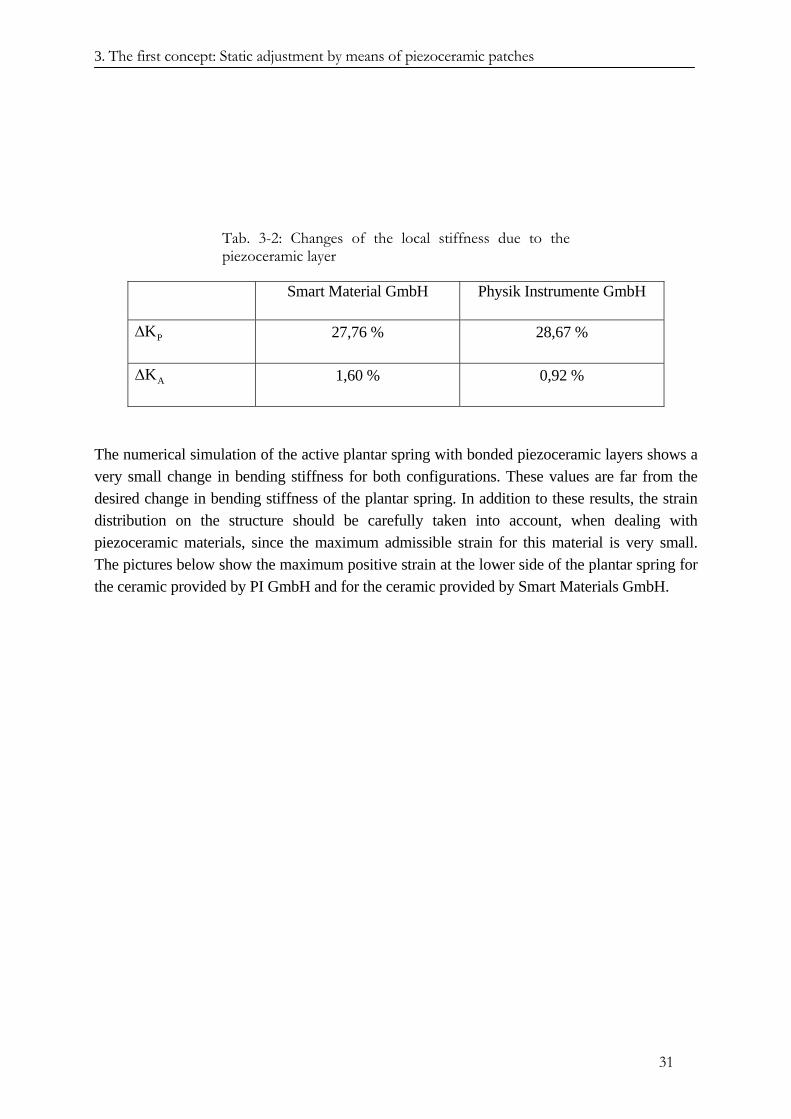
3. The first concept: Static adjustment by means of piezoceramic patches
31
Tab. 3-2: Changes of the local stiffness due to the piezoceramic layer
Smart Material GmbH Physik Instrumente GmbH
PK∆ 27,76 % 28,67 %
AK∆ 1,60 % 0,92 %
The numerical simulation of the active plantar spring with bonded piezoceramic layers shows a very small change in bending stiffness for both configurations. These values are far from the desired change in bending stiffness of the plantar spring. In addition to these results, the strain distribution on the structure should be carefully taken into account, when dealing with piezoceramic materials, since the maximum admissible strain for this material is very small. The pictures below show the maximum positive strain at the lower side of the plantar spring for the ceramic provided by PI GmbH and for the ceramic provided by Smart Materials GmbH.
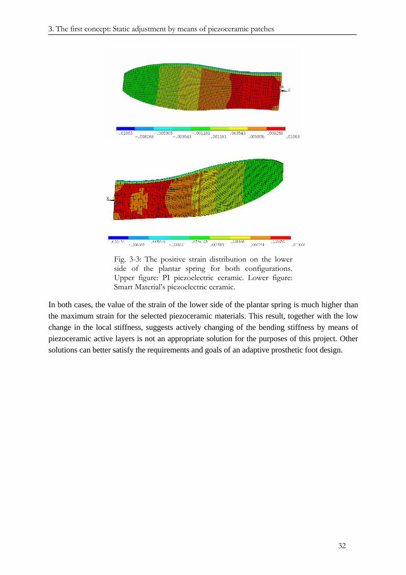
3. The first concept: Static adjustment by means of piezoceramic patches
32
Fig. 3-3: The positive strain distribution on the lower side of the plantar spring for both configurations. Upper figure: PI piezoelectric ceramic. Lower figure: Smart Material’s piezoelectric ceramic.
In both cases, the value of the strain of the lower side of the plantar spring is much higher than the maximum strain for the selected piezoceramic materials. This result, together with the low change in the local stiffness, suggests actively changing of the bending stiffness by means of piezoceramic active layers is not an appropriate solution for the purposes of this project. Other solutions can better satisfy the requirements and goals of an adaptive prosthetic foot design.

3. The first concept: Static adjustment by means of piezoceramic patches
33
REFERENCES CHAPTER III
[3.1] K. Ruschmeyer: „Piezokeramik – Grundlagen, Werkstoffe, Applikationen“, Expert Verlag, 1995
[3.2] Szabò: „Einführung in die Technische Mechanik“, Springer-Verlag, 1984.
[3.3] E.F. Crawley, J. de Luis: “Use of Piezoelectric Actuators as Element of intelligent Structures”, AIAA Journal, Vol. 25, No. 10, 1987.
[3.4] E.F. Crawley, E.H. Anderson: “Detailed Models of Piezoceramic Actuation of Beams”, J. Intell. Mat. System. Struct., I, 4-25, 1990.
[3.5] P. Gaudenzi, R. Barboni: “Static Adjustment of Beam Deflections by Means of Induced Strain Actuators”, Smart Mater. Struct., 8, 1999.
[3.6] R. Barboni, P. Gaudenzi, G. Strambi: “ On the modelling of actuator-structure interaction in intelligent structures”, 8th CIMTEC, World Ceramic Congress Forum on New Materials – Techma, Faenza, 1994.
[3.7] R.B. Williams, D.J. Inman: “An overview of composite actuators with piezoceramic fibers”, publication on the web site of the company Smart Materials – www.smart-materials.com.
4 The second concept: The plantar spring based on the active elliptical tubes
4. The second concept: The plantar spring based on the active elliptical tubes
The previous finite element model analysis of the foot provided by Otto Bock GmbH has shown that the C-spring and the plantar spring play different roles concerning the deformation of the foot during the stance phase. The deformation of the C-spring has little effect on the deformed shape of the foot, during stance, for the gait phases following the loading response. The elastic properties of the plantar springs mainly affect the distribution of the ground reaction force and its position with respect to the areas in contact with the ground. Therefore, the shape assumed by the plantar spring greatly influences the gait dynamic of the patient.
Considering the selected load condition and the position of the plantar spring with respect to the other elements of the foot, the latter can be considered as a cantilever beam clamped in correspondence to the connection with the C-spring and with the heel element.
The deformation of the plantar spring for the considered load condition depends on its bending stiffness. Considering isotropic material properties for the plantar spring, the bending stiffness B of an arbitrary cross-section of the beam is calculated by the product between the Young’s modulus E of the selected material and the inertia moment I of the structure’s cross-section. Considering a beam with uniform cross-section, the bending stiffness reads:
B E I= ⋅ (4.1) The bending stiffness B is a linear function of the quantities E and I. Potentially, both offer the possibility for actively changing the bending stiffness of the plantar spring.
The stiffness of the plantar spring, in relation to the point of application of the bending load F, has already been defined as:
LL
FKw
= (4.2)
w represents the displacement of the beam at the point of force application, located at distance L from the clamped cross-section. The vertical displacement of the beam for the selected boundary conditions, and for the concentrated bending load at distance L, is given by:
3
LF Lw3 B
⋅=
⋅ (4.3)
The stiffness of the beam may be expressed as:
L 3
3 BKL⋅
= (4.4)
34
4 The second concept: The plantar spring based on the active elliptical tubes
The stiffness is a linear function of the bending stiffness B of the beam. Assuming for the bending stiffness B a new value B*, resulting from a variation in one or both the quantities E and I, the local stiffness will change accordingly.
K
K
The new value B* of the bending stiffness B can then be defined as the sum of the original value B and its variation given by: B∆
E I∆ ⋅
(4.5) B B* B (E I)∆ = − = ∆ ⋅ =
E I⋅ ∆
where in (4.5) only a variation of one of the values E and I has been considered. This approach to actively changing the bending stiffness of the plantar spring differs from that employed in the Chapter III. In this case, the desired variation in the properties of the structure does not change the shape of the structure itself by exerting active forces or moments which change the displaced configuration of the plantar spring. The elastic properties of the beam are changed, but both strategies result in a varied static response bythe plantar spring.
In the following, the possibilities of varying the quantities E and I are discussed, in order to achieve the desired change in bending stiffness.
4.1. Change in Young’s modulus
The possibility of changing the value of the elastic modulus depends on the properties of the material employed in manufacturing the plantar spring. For instance, shape memory alloys reflect a temperature dependent Young’s modulus. Actively changing the value of the Young’s modulus value of the active component material, relies on the transition of the alloy between two phases. By heating the material from a temperature below the “austenite start” temperature, the crystal structure of the material changes from the martensitic phase to the austenitic phase. The transition of the lattice structure causes a dramatic change in the mechanical properties of the material, with an increased value of the elastic modulus. In turn, upon cooling from a temperature above the “martensitic start” value, the lattice structure changes from austenitic to martensitic, and consequently the Young’s modulus decreases.
The transition temperatures and elastic modulus value of the material depend on the alloy. According to [3.2], the value of the Young’s modulus changes from 30 GPa in the martensitic phase to the 70 GPa in the austenitic phase.
4.2. Change in the moment of inertia of the beam cross-section
The second possibility for actively changing the bending stiffness of the foot is to change the inertia moment of the cantilever beam cross-sections, representing the plantar spring.
The value of the moment of inertia depends on the geometric characteristics of the beam’s cross-section. Considering a rectangular shaped cross-section and referring to s and h for the width and height of the beam’s cross-section, respectively, the moment of inertia is given by:
35
4 The second concept: The plantar spring based on the active elliptical tubes
3hI s12
= ⋅ (4.6)
The quantity I depends linearly on the width of the cross-section and on the third power of the height . This relation suggests the possibility to change the bending stiffness of the beam by varying the height of the cross-section, since small changes of this geometric dimension will lead to larger changes in the moment of inertia, and therefore in the bending stiffness. Any solution able to realise the desired change in the moment of inertia by changing the vertical dimension of the cross-section, should preserve, as much as possible, the basic characteristics of the foot in terms of dimensions, weight, safety and walking comfort. There are two possibilities for achieving this result. The first one deals with a system of very stiff bodies linked with low stiffness elements or joints that, in response to the actions generated by appropriate actuators, is able to change the form of the cross-section in order to realise the desired shape, to achieve change in the moment of inertia. The second possibility takes advantage of the elasticity of the structure itself: By introducing forces into the plantar spring system, it is possible to deform the cross-section to achieve the desired change in the moment of inertia, and therefore, in the bending stiffness. The latter solution is preferred, since it presents a higher structural integration of the different elements and lower complexity in terms of moving parts. Furthermore, this solution is expected to be lighter than the first proposed method, as, for instance, was stated by Campanile in [4.2]. Depending on the selected solution, the possibility of changing the moment of inertia is limited by the maximum admissible deformation for the selected material. This condition restricts the efficiency of the solution’s ability to translate the concept in a practical application.
sh
A concept which is able to deform the shape of the beam’s cross-section and therefore, to vary the moment of inertia, is a beam with a hollow cross-section; filling the hollow beam with a fluid, the cross-section can be deformed by increasing the inner pressure of the fluid in the beam. The selection of the geometry of the cross-section greatly influences the shape that it assumes when reacting to the inner pressure, and therefore, the effectiveness of the proposed concept. For this purpose, a closed, thin-walled cross-section meets the requirements of the proposed concept, and provides a lightweight structure, since the weight of the prosthetic foot is an important characteristic to take into account5.
As already mentioned, the purpose of the concept is to deform the cross-section in order to increase its moment of inertia, which contributes to its bending stiffness. Among several possibilities, the elliptical shape presents interesting properties: Depending on the geometry of the cross-section, defined by the length of the semi-axes and by the wall thickness, the inner pressure leads to a shortening of the major semi-axis a and to a lengthening of the minor semi-axis b (see Fig. 4-1). The variation in the length of the semi-axes depends on the ratio δ between b and a, and on the inner pressure applied. The purpose is now the design of the elliptical cross-section, with the ability to achieve the desired variation in the bending stiffness. Furthermore, it 5 The weight of the 1C40 foot by Otto Bock GmbH is about 663 g, including of the adapter for the connection to the pylon.
36
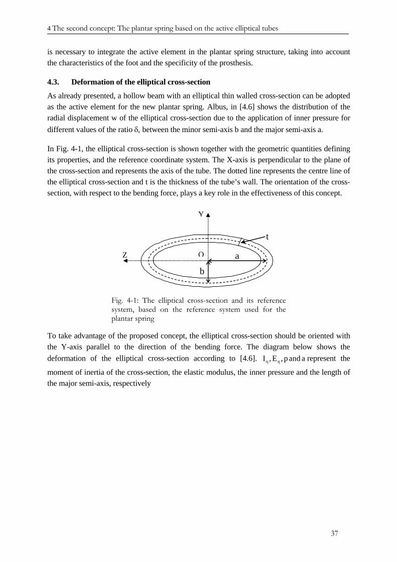
4 The second concept: The plantar spring based on the active elliptical tubes
is necessary to integrate the active element in the plantar spring structure, taking into account the characteristics of the foot and the specificity of the prosthesis.
4.3. Deformation of the elliptical cross-section
As already presented, a hollow beam with an elliptical thin walled cross-section can be adopted as the active element for the new plantar spring. Albus, in [4.6] shows the distribution of the radial displacement w of the elliptical cross-section due to the application of inner pressure for different values of the ratio δ, between the minor semi-axis b and the major semi-axis a.
In Fig. 4-1, the elliptical cross-section is shown together with the geometric quantities defining its properties, and the reference coordinate system. The X-axis is perpendicular to the plane of the cross-section and represents the axis of the tube. The dotted line represents the centre line of the elliptical cross-section and t is the thickness of the tube’s wall. The orientation of the cross-section, with respect to the bending force, plays a key role in the effectiveness of this concept.
Y
Z a
b
O
t
Fig. 4-1: The elliptical cross-section and its reference system, based on the reference system used for the plantar spring
To take advantage of the proposed concept, the elliptical cross-section should be oriented with the Y-axis parallel to the direction of the bending force. The diagram below shows the deformation of the elliptical cross-section according to [4.6]. I , E , p and aη η represent the
moment of inertia of the cross-section, the elastic modulus, the inner pressure and the length of the major semi-axis, respectively
37
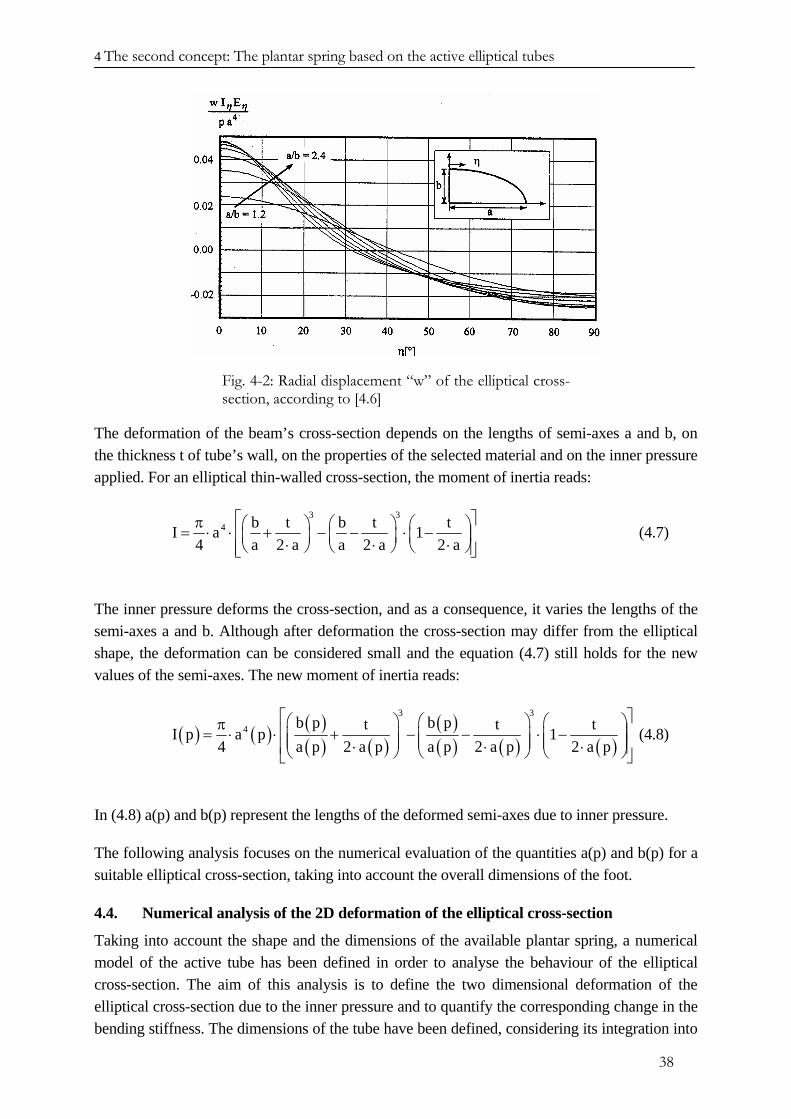
4 The second concept: The plantar spring based on the active elliptical tubes
Fig. 4-2: Radial displacement “w” of the elliptical cross-section, according to [4.6]
The deformation of the beam’s cross-section depends on the lengths of semi-axes a and b, on the thickness t of tube’s wall, on the properties of the selected material and on the inner pressure applied. For an elliptical thin-walled cross-section, the moment of inertia reads:
3 34 b t b t tI a 1
4 a 2 a a 2 a 2 a⎡ ⎤π ⎛ ⎞ ⎛ ⎞ ⎛= ⋅ ⋅ + − − ⋅ − ⎞⎢ ⎥⎜ ⎟ ⎜ ⎟ ⎜⋅ ⋅⎝ ⎠ ⎝ ⎠ ⎝
⎟⋅ ⎠⎢ ⎥⎣ ⎦ (4.7)
The inner pressure deforms the cross-section, and as a consequence, it varies the lengths of the semi-axes a and b. Although after deformation the cross-section may differ from the elliptical shape, the deformation can be considered small and the equation (4.7) still holds for the new values of the semi-axes. The new moment of inertia reads:
( ) ( ) ( )( ) ( )
( )( ) ( ) ( )
3 3
4 b p b pt tI p a p 14 a p 2 a p a p 2 a p 2 a p
⎡ ⎤⎛ ⎞ ⎛ ⎞ ⎛π ⎢ ⎥= ⋅ ⋅ + − − ⋅ −⎜ ⎟ ⎜ ⎟ ⎜⎜ ⎟ ⎜ ⎟ ⎜⋅ ⋅⎢ ⎥⎝ ⎠ ⎝ ⎠ ⎝⎣ ⎦
t ⎞⎟⎟⋅ ⎠
(4.8)
In (4.8) a(p) and b(p) represent the lengths of the deformed semi-axes due to inner pressure.
The following analysis focuses on the numerical evaluation of the quantities a(p) and b(p) for a suitable elliptical cross-section, taking into account the overall dimensions of the foot.
4.4. Numerical analysis of the 2D deformation of the elliptical cross-section
Taking into account the shape and the dimensions of the available plantar spring, a numerical model of the active tube has been defined in order to analyse the behaviour of the elliptical cross-section. The aim of this analysis is to define the two dimensional deformation of the elliptical cross-section due to the inner pressure and to quantify the corresponding change in the bending stiffness. The dimensions of the tube have been defined, considering its integration into
38
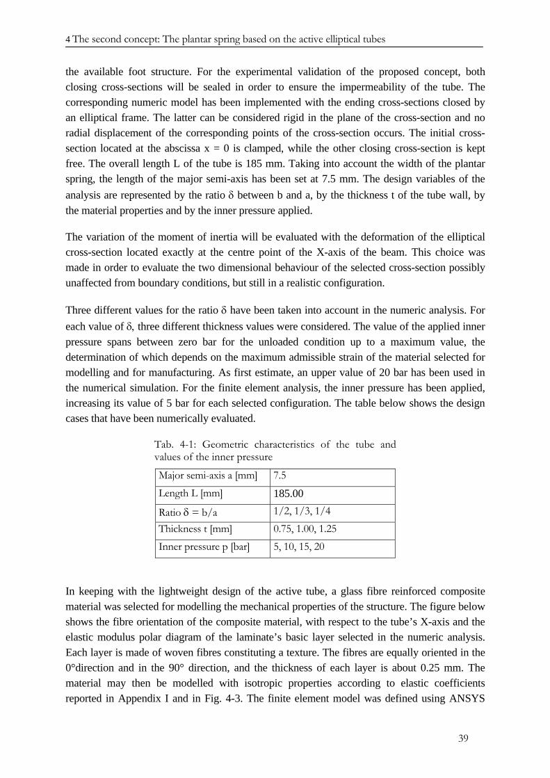
4 The second concept: The plantar spring based on the active elliptical tubes
the available foot structure. For the experimental validation of the proposed concept, both closing cross-sections will be sealed in order to ensure the impermeability of the tube. The corresponding numeric model has been implemented with the ending cross-sections closed by an elliptical frame. The latter can be considered rigid in the plane of the cross-section and no radial displacement of the corresponding points of the cross-section occurs. The initial cross-section located at the abscissa x = 0 is clamped, while the other closing cross-section is kept free. The overall length L of the tube is 185 mm. Taking into account the width of the plantar spring, the length of the major semi-axis has been set at 7.5 mm. The design variables of the analysis are represented by the ratio δ between b and a, by the thickness t of the tube wall, by the material properties and by the inner pressure applied.
The variation of the moment of inertia will be evaluated with the deformation of the elliptical cross-section located exactly at the centre point of the X-axis of the beam. This choice was made in order to evaluate the two dimensional behaviour of the selected cross-section possibly unaffected from boundary conditions, but still in a realistic configuration.
Three different values for the ratio δ have been taken into account in the numeric analysis. For each value of δ, three different thickness values were considered. The value of the applied inner pressure spans between zero bar for the unloaded condition up to a maximum value, the determination of which depends on the maximum admissible strain of the material selected for modelling and for manufacturing. As first estimate, an upper value of 20 bar has been used in the numerical simulation. For the finite element analysis, the inner pressure has been applied, increasing its value of 5 bar for each selected configuration. The table below shows the design cases that have been numerically evaluated.
Tab. 4-1: Geometric characteristics of the tube and values of the inner pressure
Major semi-axis a [mm] 7.5 Length L [mm] 185.00
Ratio δ = b/a 1/2, 1/3, 1/4 Thickness t [mm] 0.75, 1.00, 1.25 Inner pressure p [bar] 5, 10, 15, 20
In keeping with the lightweight design of the active tube, a glass fibre reinforced composite material was selected for modelling the mechanical properties of the structure. The figure below shows the fibre orientation of the composite material, with respect to the tube’s X-axis and the elastic modulus polar diagram of the laminate’s basic layer selected in the numeric analysis. Each layer is made of woven fibres constituting a texture. The fibres are equally oriented in the 0°direction and in the 90° direction, and the thickness of each layer is about 0.25 mm. The material may then be modelled with isotropic properties according to elastic coefficients reported in Appendix I and in Fig. 4-3. The finite element model was defined using ANSYS
39
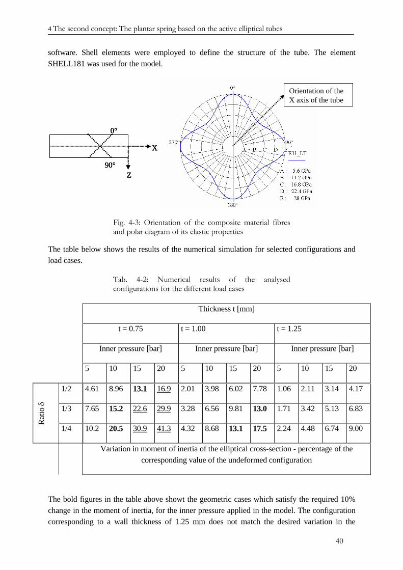
4 The second concept: The plantar spring based on the active elliptical tubes
software. Shell elements were employed to define the structure of the tube. The element SHELL181 was used for the model.
Orientation of theX axis of the tube
X
Z
0°
90°
Orientation of theX axis of the tubeOrientation of theX axis of the tube
X
Z
0°
90°
X
Z
0°
90°
Fig. 4-3: Orientation of the composite material fibres and polar diagram of its elastic properties
The table below shows the results of the numerical simulation for selected configurations and load cases.
Tab. 4-2: Numerical results of the analysed configurations for the different load cases
The bold figures in the table above showt the geometric cases which satisfy the required 10% change in the moment of inertia, for the inner pressure applied in the model. The configuration corresponding to a wall thickness of 1.25 mm does not match the desired variation in the
Thickness t [mm]
t = 0.75 t = 1.00 t = 1.25
Inner pressure [bar] Inner pressure [bar] Inner pressure [bar]
5 10 15 20 5 10 15 20 5 10 15 20
1/2 4.61 8.96 13.1 16.9 2.01 3.98 6.02 7.78 1.06 2.11 3.14 4.17
1/3 7.65 15.2 22.6 29.9 3.28 6.56 9.81 13.0 1.71 3.42 5.13 6.83
Rat
io δ
1/4 10.2 20.5 30.9 41.3 4.32 8.68 13.1 17.5 2.24 4.48 6.74 9.00
Variation in moment of inertia of the elliptical cross-section - percentage of the
corresponding value of the undeformed configuration
40
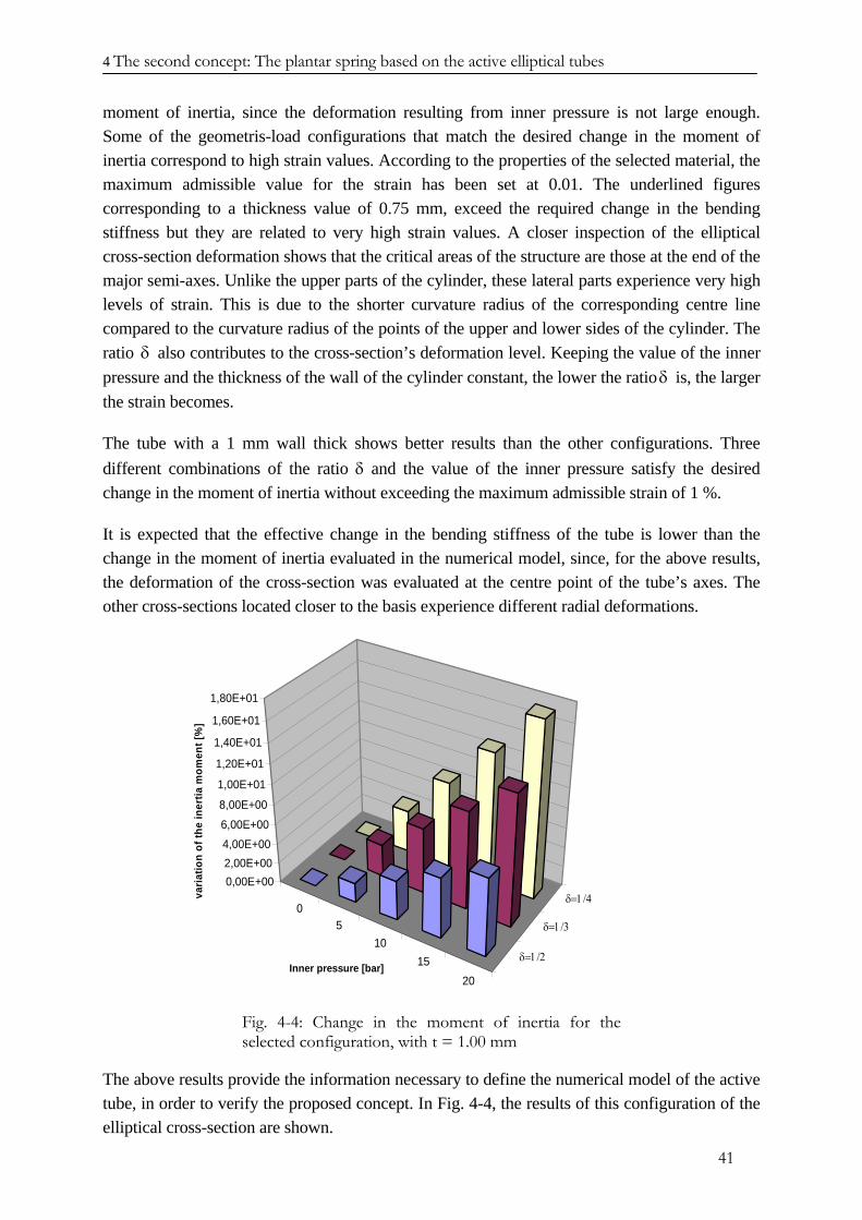
4 The second concept: The plantar spring based on the active elliptical tubes
moment of inertia, since the deformation resulting from inner pressure is not large enough. Some of the geometris-load configurations that match the desired change in the moment of inertia correspond to high strain values. According to the properties of the selected material, the maximum admissible value for the strain has been set at 0.01. The underlined figures corresponding to a thickness value of 0.75 mm, exceed the required change in the bending stiffness but they are related to very high strain values. A closer inspection of the elliptical cross-section deformation shows that the critical areas of the structure are those at the end of the major semi-axes. Unlike the upper parts of the cylinder, these lateral parts experience very high levels of strain. This is due to the shorter curvature radius of the corresponding centre line compared to the curvature radius of the points of the upper and lower sides of the cylinder. The ratio also contributes to the cross-section’s deformation level. Keeping the value of the inner pressure and the thickness of the wall of the cylinder constant, the lower the ratio δ is, the larger the strain becomes.
δ
The tube with a 1 mm wall thick shows better results than the other configurations. Three different combinations of the ratio δ and the value of the inner pressure satisfy the desired change in the moment of inertia without exceeding the maximum admissible strain of 1 %.
It is expected that the effective change in the bending stiffness of the tube is lower than the change in the moment of inertia evaluated in the numerical model, since, for the above results, the deformation of the cross-section was evaluated at the centre point of the tube’s axes. The other cross-sections located closer to the basis experience different radial deformations.
05
1015
20
δ=1/2
δ=1/3
δ=1/40,00E+002,00E+004,00E+006,00E+00
8,00E+00
1,00E+01
1,20E+01
1,40E+01
1,60E+01
1,80E+01
varia
tion
of th
e in
ertia
mom
ent [
%]
Inner pressure [bar]
Fig. 4-4: Change in the moment of inertia for the selected configuration, with t = 1.00 mm
The above results provide the information necessary to define the numerical model of the active tube, in order to verify the proposed concept. In Fig. 4-4, the results of this configuration of the elliptical cross-section are shown.
41
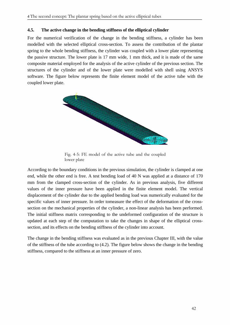
4 The second concept: The plantar spring based on the active elliptical tubes
4.5. The active change in the bending stiffness of the elliptical cylinder
For the numerical verification of the change in the bending stiffness, a cylinder has been modelled with the selected elliptical cross-section. To assess the contribution of the plantar spring to the whole bending stiffness, the cylinder was coupled with a lower plate representing the passive structure. The lower plate is 17 mm wide, 1 mm thick, and it is made of the same composite material employed for the analysis of the active cylinder of the previous section. The structures of the cylinder and of the lower plate were modelled with shell using ANSYS software. The figure below represents the finite element model of the active tube with the coupled lower plate.
Fig. 4-5: FE model of the active tube and the coupled lower plate
According to the boundary conditions in the previous simulation, the cylinder is clamped at one end, while the other end is free. A test bending load of 40 N was applied at a distance of 170 mm from the clamped cross-section of the cylinder. As in previous analysis, five different values of the inner pressure have been applied in the finite element model. The vertical displacement of the cylinder due to the applied bending load was numerically evaluated for the specific values of inner pressure. In order tomeasure the effect of the deformation of the cross-section on the mechanical properties of the cylinder, a non-linear analysis has been performed. The initial stiffness matrix corresponding to the undeformed configuration of the structure is updated at each step of the computation to take the changes in shape of the elliptical cross-section, and its effects on the bending stiffness of the cylinder into account.
The change in the bending stiffness was evaluated as in the previous Chapter III, with the value of the stiffness of the tube according to (4.2). The figure below shows the change in the bending stiffness, compared to the stiffness at an inner pressure of zero.
42
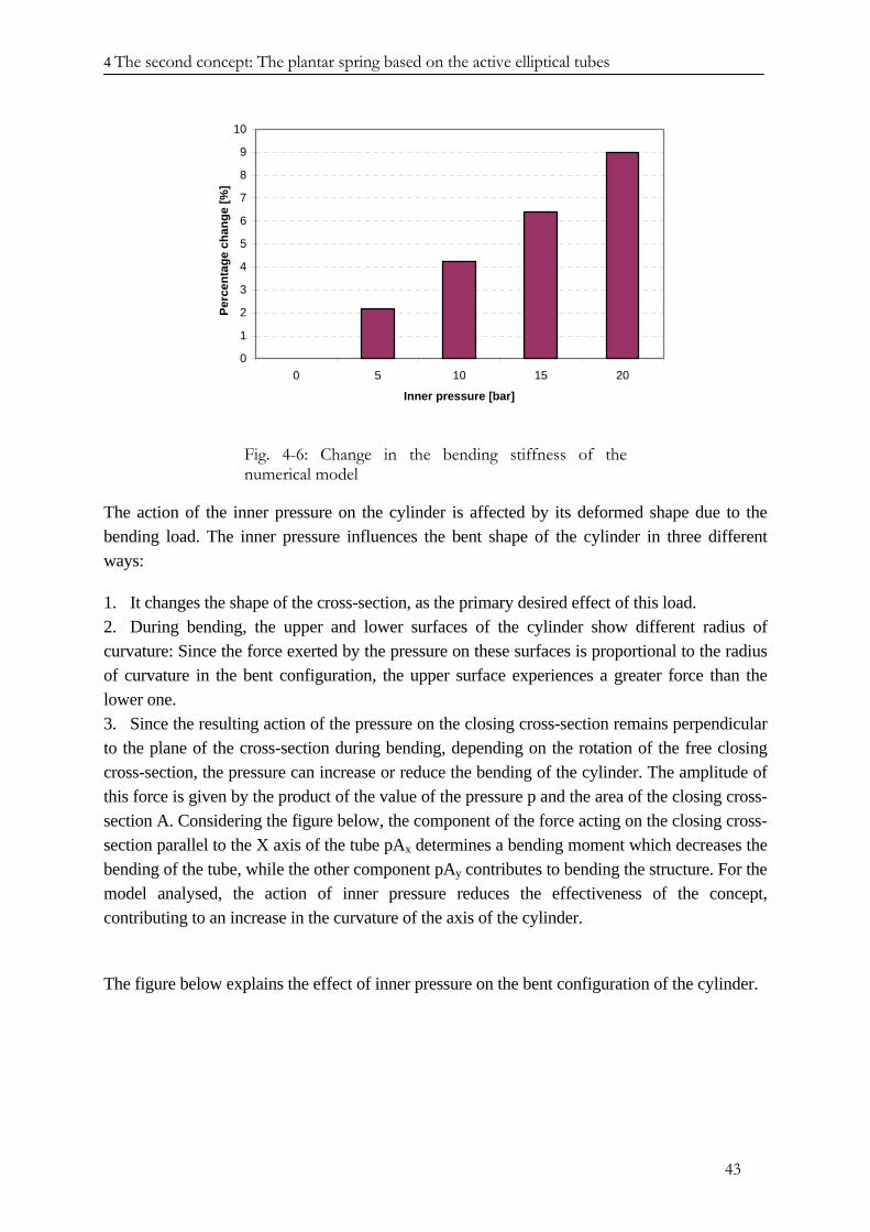
4 The second concept: The plantar spring based on the active elliptical tubes
0
1
2
3
4
5
6
7
8
9
10
0 5 10 15 20
Inner pressure [bar]
Perc
enta
ge c
hang
e [%
]
Fig. 4-6: Change in the bending stiffness of the numerical model
The action of the inner pressure on the cylinder is affected by its deformed shape due to the bending load. The inner pressure influences the bent shape of the cylinder in three different ways:
1. It changes the shape of the cross-section, as the primary desired effect of this load. 2. During bending, the upper and lower surfaces of the cylinder show different radius of curvature: Since the force exerted by the pressure on these surfaces is proportional to the radius of curvature in the bent configuration, the upper surface experiences a greater force than the lower one. 3. Since the resulting action of the pressure on the closing cross-section remains perpendicular to the plane of the cross-section during bending, depending on the rotation of the free closing cross-section, the pressure can increase or reduce the bending of the cylinder. The amplitude of this force is given by the product of the value of the pressure p and the area of the closing cross-section A. Considering the figure below, the component of the force acting on the closing cross-section parallel to the X axis of the tube pAx determines a bending moment which decreases the bending of the tube, while the other component pAy contributes to bending the structure. For the model analysed, the action of inner pressure reduces the effectiveness of the concept, contributing to an increase in the curvature of the axis of the cylinder.
The figure below explains the effect of inner pressure on the bent configuration of the cylinder.
43
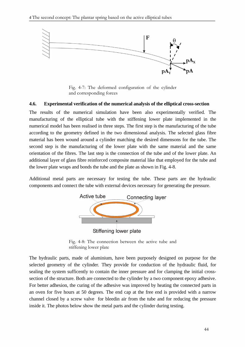
4 The second concept: The plantar spring based on the active elliptical tubes
[4.1] 4.12
4.10[4.8
[4.6F
pA
pAX
pAY
θ
Fig. 4-7: The deformed configuration of the cylinder and corresponding forces
4.6. Experimental verification of the numerical analysis of the elliptical cross-section
The results of the numerical simulation have been also experimentally verified. The manufacturing of the elliptical tube with the stiffening lower plate implemented in the numerical model has been realised in three steps. The first step is the manufacturing of the tube according to the geometry defined in the two dimensional analysis. The selected glass fibre material has been wound around a cylinder matching the desired dimensons for the tube. The second step is the manufacturing of the lower plate with the same material and the same orientation of the fibres. The last step is the connection of the tube and of the lower plate. An additional layer of glass fibre reinforced composite material like that employed for the tube and the lower plate wraps and bonds the tube and the plate as shown in Fig. 4-8.
Additional metal parts are necessary for testing the tube. These parts are the hydraulic components and connect the tube with external devices necessary for generating the pressure.
Fig. 4-8: The connection between the active tube and stiffening lower plate
The hydraulic parts, made of aluminium, have been purposely designed on purpose for the selected geometry of the cylinder. They provide for conduction of the hydraulic fluid, for sealing the system sufficently to contain the inner pressure and for clamping the initial cross-section of the structure. Both are connected to the cylinder by a two component epoxy adhesive. For better adhesion, the curing of the adhesive was improved by heating the connected parts in an oven for five hours at 50 degrees. The end cap at the free end is provided with a narrow channel closed by a screw valve for bleedin air from the tube and for reducing the pressure inside it. The photos below show the metal parts and the cylinder during testing.
44
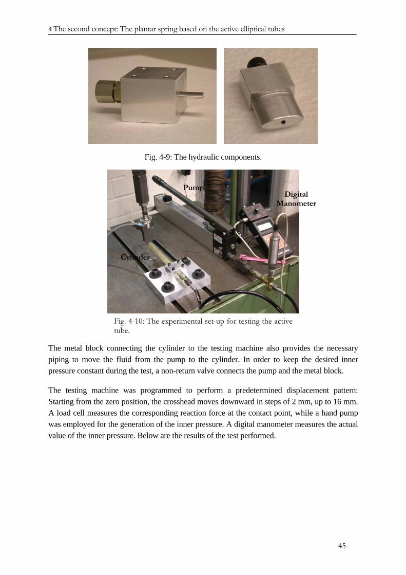
4 The second concept: The plantar spring based on the active elliptical tubes
PumpDigital
Manometer
Cylinder
Fig. 4-9: The hydraulic components.
Fig. 4-10: The experimental set-up for testing the active tube.
The metal block connecting the cylinder to the testing machine also provides the necessary piping to move the fluid from the pump to the cylinder. In order to keep the desired inner pressure constant during the test, a non-return valve connects the pump and the metal block.
The testing machine was programmed to perform a predetermined displacement pattern: Starting from the zero position, the crosshead moves downward in steps of 2 mm, up to 16 mm. A load cell measures the corresponding reaction force at the contact point, while a hand pump was employed for the generation of the inner pressure. A digital manometer measures the actual value of the inner pressure. Below are the results of the test performed.
45
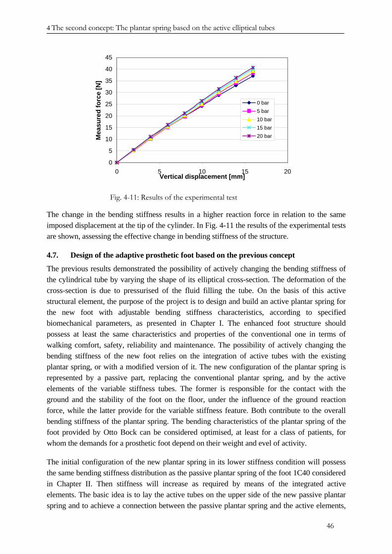
4 The second concept: The plantar spring based on the active elliptical tubes
0
5
10
15
20
25
30
35
40
45
0 5 10 15 20Vertical displacement [mm]
Mea
sure
d fo
rce
[N]
0 bar5 bar10 bar15 bar20 bar
Fig. 4-11: Results of the experimental test
The change in the bending stiffness results in a higher reaction force in relation to the same imposed displacement at the tip of the cylinder. In Fig. 4-11 the results of the experimental tests are shown, assessing the effective change in bending stiffness of the structure.
4.7. Design of the adaptive prosthetic foot based on the previous concept
The previous results demonstrated the possibility of actively changing the bending stiffness of the cylindrical tube by varying the shape of its elliptical cross-section. The deformation of the cross-section is due to pressurised of the fluid filling the tube. On the basis of this active structural element, the purpose of the project is to design and build an active plantar spring for the new foot with adjustable bending stiffness characteristics, according to specified biomechanical parameters, as presented in Chapter I. The enhanced foot structure should possess at least the same characteristics and properties of the conventional one in terms of walking comfort, safety, reliability and maintenance. The possibility of actively changing the bending stiffness of the new foot relies on the integration of active tubes with the existing plantar spring, or with a modified version of it. The new configuration of the plantar spring is represented by a passive part, replacing the conventional plantar spring, and by the active elements of the variable stiffness tubes. The former is responsible for the contact with the ground and the stability of the foot on the floor, under the influence of the ground reaction force, while the latter provide for the variable stiffness feature. Both contribute to the overall bending stiffness of the plantar spring. The bending characteristics of the plantar spring of the foot provided by Otto Bock can be considered optimised, at least for a class of patients, for whom the demands for a prosthetic foot depend on their weight and evel of activity.
The initial configuration of the new plantar spring in its lower stiffness condition will possess the same bending stiffness distribution as the passive plantar spring of the foot 1C40 considered in Chapter II. Then stiffness will increase as required by means of the integrated active elements. The basic idea is to lay the active tubes on the upper side of the new passive plantar spring and to achieve a connection between the passive plantar spring and the active elements,
46
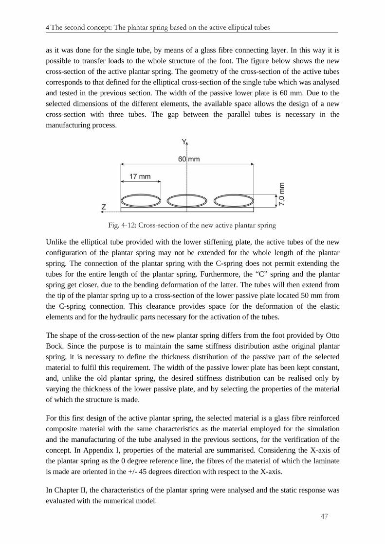
4 The second concept: The plantar spring based on the active elliptical tubes
as it was done for the single tube, by means of a glass fibre connecting layer. In this way it is possible to transfer loads to the whole structure of the foot. The figure below shows the new cross-section of the active plantar spring. The geometry of the cross-section of the active tubes corresponds to that defined for the elliptical cross-section of the single tube which was analysed and tested in the previous section. The width of the passive lower plate is 60 mm. Due to the selected dimensions of the different elements, the available space allows the design of a new cross-section with three tubes. The gap between the parallel tubes is necessary in the manufacturing process.
Fig. 4-12: Cross-section of the new active plantar spring
Unlike the elliptical tube provided with the lower stiffening plate, the active tubes of the new configuration of the plantar spring may not be extended for the whole length of the plantar spring. The connection of the plantar spring with the C-spring does not permit extending the tubes for the entire length of the plantar spring. Furthermore, the “C” spring and the plantar spring get closer, due to the bending deformation of the latter. The tubes will then extend from the tip of the plantar spring up to a cross-section of the lower passive plate located 50 mm from the C-spring connection. This clearance provides space for the deformation of the elastic elements and for the hydraulic parts necessary for the activation of the tubes.
The shape of the cross-section of the new plantar spring differs from the foot provided by Otto Bock. Since the purpose is to maintain the same stiffness distribution asthe original plantar spring, it is necessary to define the thickness distribution of the passive part of the selected material to fulfil this requirement. The width of the passive lower plate has been kept constant, and, unlike the old plantar spring, the desired stiffness distribution can be realised only by varying the thickness of the lower passive plate, and by selecting the properties of the material of which the structure is made.
For this first design of the active plantar spring, the selected material is a glass fibre reinforced composite material with the same characteristics as the material employed for the simulation and the manufacturing of the tube analysed in the previous sections, for the verification of the concept. In Appendix I, properties of the material are summarised. Considering the X-axis of the plantar spring as the 0 degree reference line, the fibres of the material of which the laminate is made are oriented in the +/- 45 degrees direction with respect to the X-axis.
In Chapter II, the characteristics of the plantar spring were analysed and the static response was evaluated with the numerical model.
47
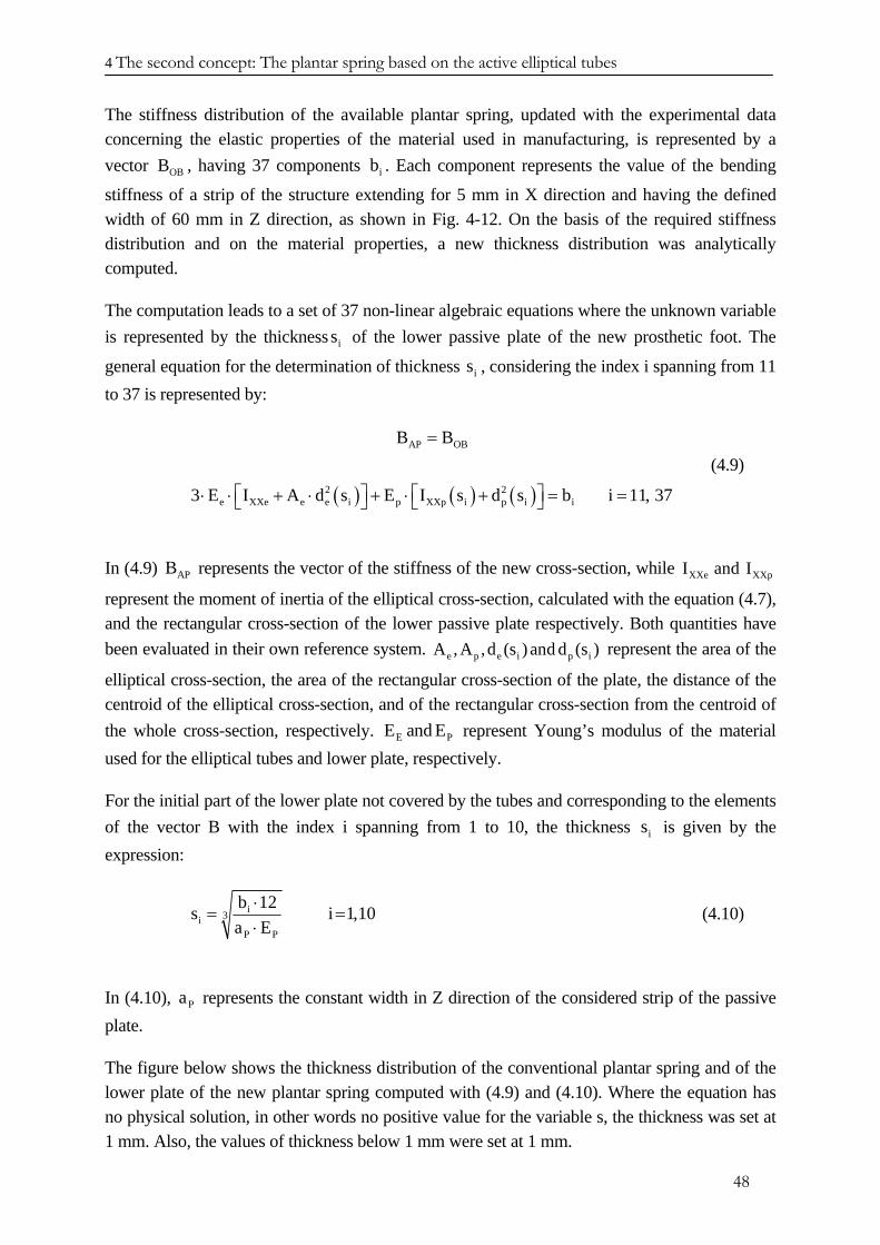
4 The second concept: The plantar spring based on the active elliptical tubes
The stiffness distribution of the available plantar spring, updated with the experimental data concerning the elastic properties of the material used in manufacturing, is represented by a vector , having 37 components OBB ib . Each component represents the value of the bending
stiffness of a strip of the structure extending for 5 mm in X direction and having the defined width of 60 mm in Z direction, as shown in Fig. 4-12. On the basis of the required stiffness distribution and on the material properties, a new thickness distribution was analytically computed.
The computation leads to a set of 37 non-linear algebraic equations where the unknown variable is represented by the thickness of the lower passive plate of the new prosthetic foot. The
general equation for the determination of thickness , considering the index i spanning from 11 to 37 is represented by:
is
is
( ) ( ) ( )
AP OB
2 2e XXe e e i p XXp i p i i
B B
3 E I A d s E I s d s b i 11, 37
=
⎡ ⎤ ⎡ ⎤⋅ ⋅ + ⋅ + ⋅ + = =⎣ ⎦ ⎣ ⎦
(4.9)
In (4.9) represents the vector of the stiffness of the new cross-section, while
represent the moment of inertia of the elliptical cross-section, calculated with the equation (4.7), and the rectangular cross-section of the lower passive plate respectively. Both quantities have been evaluated in their own reference system. represent the area of the
elliptical cross-section, the area of the rectangular cross-section of the plate, the distance of the centroid of the elliptical cross-section, and of the rectangular cross-section from the centroid of the whole cross-section, respectively. represent Young’s modulus of the material used for the elliptical tubes and lower plate, respectively.
APB XXe XXpI and I
e p e i p iA , A ,d (s ) and d (s )
EE and EP
For the initial part of the lower plate not covered by the tubes and corresponding to the elements of the vector B with the index i spanning from 1 to 10, the thickness is given by the expression:
is
i3iP P
b 12sa E
⋅=
⋅i 1,10= (4.10)
In (4.10), represents the constant width in Z direction of the considered strip of the passive plate.
Pa
The figure below shows the thickness distribution of the conventional plantar spring and of the lower plate of the new plantar spring computed with (4.9) and (4.10). Where the equation has no physical solution, in other words no positive value for the variable s, the thickness was set at 1 mm. Also, the values of thickness below 1 mm were set at 1 mm.
48
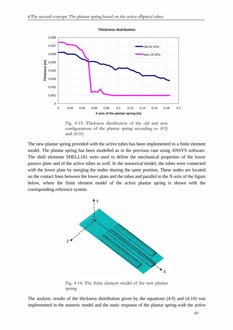
4 The second concept: The plantar spring based on the active elliptical tubes
Thickness distribution
0
0,001
0,002
0,003
0,004
0,005
0,006
0,007
0,008
0 0,02 0,04 0,06 0,08 0,1 0,12 0,14 0,16 0,18 0,2
X axis of the plantar spring [m]
Thic
knes
s [m
]Old 32 GPa
New 18 GPa
Fig. 4-13: Thickness distribution of the old and new configurations of the plantar spring according to (4.9) and (4.10)
The new plantar spring provided with the active tubes has been implemented in a finite element model. The plantar spring has been modelled as in the previous case using ANSYS software. The shell elements SHELL181 were used to define the mechanical properties of the lower passive plate and of the active tubes as well. In the numerical model, the tubes were connected with the lower plate by merging the nodes sharing the same position. These nodes are located on the contact lines between the lower plate and the tubes and parallel to the X-axis of the figure below, where the finite element model of the active plantar spring is shown with the corresponding reference system.
X
Y
Z
Fig. 4-14: The finite element model of the new plantar spring
The analytic results of the thickness distribution given by the equations (4.9) and (4.10) was implemented in the numeric model and the static response of the plantar spring with the active
49
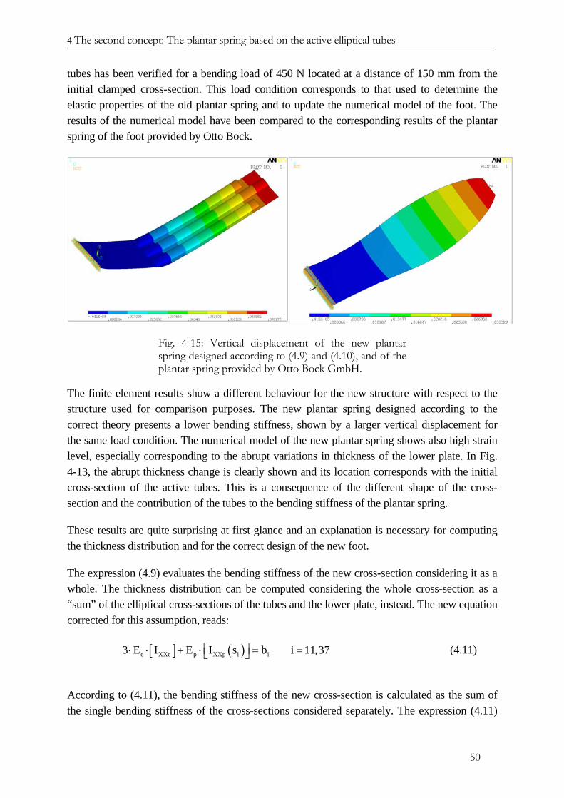
4 The second concept: The plantar spring based on the active elliptical tubes
tubes has been verified for a bending load of 450 N located at a distance of 150 mm from the initial clamped cross-section. This load condition corresponds to that used to determine the elastic properties of the old plantar spring and to update the numerical model of the foot. The results of the numerical model have been compared to the corresponding results of the plantar spring of the foot provided by Otto Bock.
Fig. 4-15: Vertical displacement of the new plantar spring designed according to (4.9) and (4.10), and of the plantar spring provided by Otto Bock GmbH.
The finite element results show a different behaviour for the new structure with respect to the structure used for comparison purposes. The new plantar spring designed according to the correct theory presents a lower bending stiffness, shown by a larger vertical displacement for the same load condition. The numerical model of the new plantar spring shows also high strain level, especially corresponding to the abrupt variations in thickness of the lower plate. In Fig. 4-13, the abrupt thickness change is clearly shown and its location corresponds with the initial cross-section of the active tubes. This is a consequence of the different shape of the cross-section and the contribution of the tubes to the bending stiffness of the plantar spring.
These results are quite surprising at first glance and an explanation is necessary for computing the thickness distribution and for the correct design of the new foot.
The expression (4.9) evaluates the bending stiffness of the new cross-section considering it as a whole. The thickness distribution can be computed considering the whole cross-section as a “sum” of the elliptical cross-sections of the tubes and the lower plate, instead. The new equation corrected for this assumption, reads:
[ ] ( )e XXe p XXp i i3 E I E I s b i 11,37⎡ ⎤⋅ ⋅ + ⋅ = =⎣ ⎦ (4.11)
According to (4.11), the bending stiffness of the new cross-section is calculated as the sum of the single bending stiffness of the cross-sections considered separately. The expression (4.11)
50
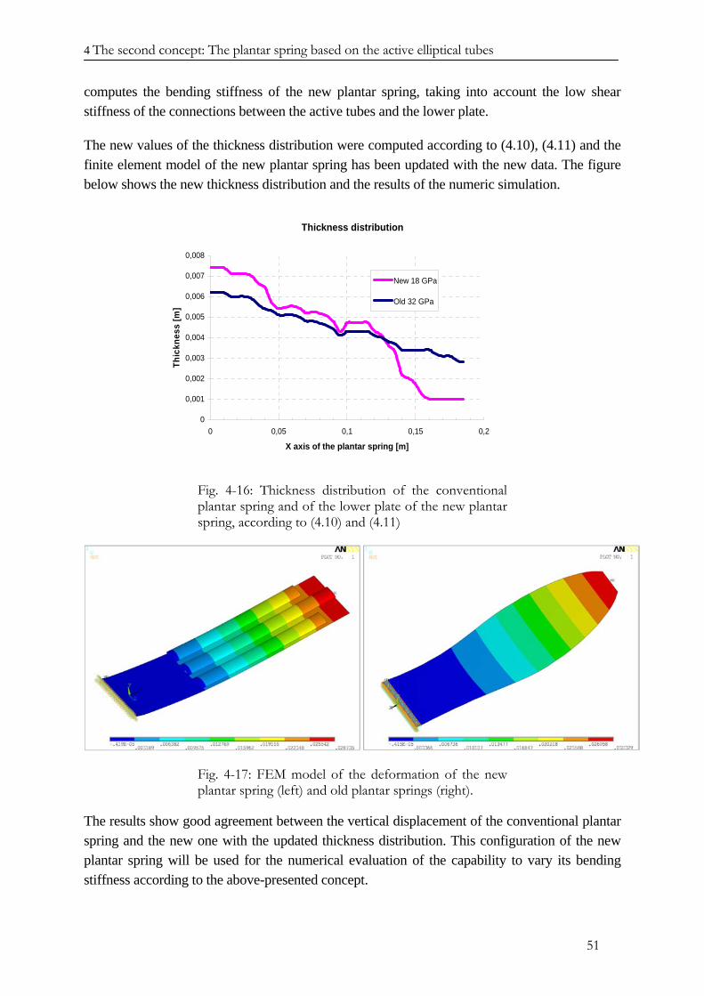
4 The second concept: The plantar spring based on the active elliptical tubes
computes the bending stiffness of the new plantar spring, taking into account the low shear stiffness of the connections between the active tubes and the lower plate.
The new values of the thickness distribution were computed according to (4.10), (4.11) and the finite element model of the new plantar spring has been updated with the new data. The figure below shows the new thickness distribution and the results of the numeric simulation.
Thickness distribution
0
0,001
0,002
0,003
0,004
0,005
0,006
0,007
0,008
0 0,05 0,1 0,15 0,2
X axis of the plantar spring [m]
Thic
knes
s [m
]
New 18 GPa
Old 32 GPa
Fig. 4-16: Thickness distribution of the conventional plantar spring and of the lower plate of the new plantar spring, according to (4.10) and (4.11)
Fig. 4-17: FEM model of the deformation of the new plantar spring (left) and old plantar springs (right).
The results show good agreement between the vertical displacement of the conventional plantar spring and the new one with the updated thickness distribution. This configuration of the new plantar spring will be used for the numerical evaluation of the capability to vary its bending stiffness according to the above-presented concept.
51
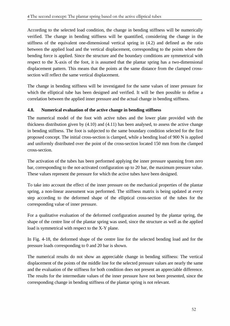
4 The second concept: The plantar spring based on the active elliptical tubes
According to the selected load condition, the change in bending stiffness will be numerically verified. The change in bending stiffness will be quantified, considering the change in the stiffness of the equivalent one-dimensional vertical spring in (4.2) and defined as the ratio between the applied load and the vertical displacement, corresponding to the points where the bending force is applied. Since the structure and the boundary conditions are symmetrical with respect to the X-axis of the foot, it is assumed that the plantar spring has a two-dimensional displacement pattern. This means that the points at the same distance from the clamped cross-section will reflect the same vertical displacement.
The change in bending stiffness will be investigated for the same values of inner pressure for which the elliptical tube has been designed and verified. It will be then possible to define a correlation between the applied inner pressure and the actual change in bending stiffness.
4.8. Numerical evaluation of the active change in bending stiffness
The numerical model of the foot with active tubes and the lower plate provided with the thickness distribution given by (4.10) and (4.11) has been analysed, to assess the active change in bending stiffness. The foot is subjected to the same boundary condition selected for the first proposed concept. The initial cross-section is clamped, while a bending load of 900 N is applied and uniformly distributed over the point of the cross-section located 150 mm from the clamped cross-section.
The activation of the tubes has been performed applying the inner pressure spanning from zero bar, corresponding to the not-activated configuration up to 20 bar, the maximum pressure value. These values represent the pressure for which the active tubes have been designed.
To take into account the effect of the inner pressure on the mechanical properties of the plantar spring, a non-linear assessment was performed. The stiffness matrix is being updated at every step according to the deformed shape of the elliptical cross-section of the tubes for the corresponding value of inner pressure.
For a qualitative evaluation of the deformed configuration assumed by the plantar spring, the shape of the centre line of the plantar spring was used, since the structure as well as the applied load is symmetrical with respect to the X-Y plane.
In Fig. 4-18, the deformed shape of the centre line for the selected bending load and for the pressure loads corresponding to 0 and 20 bar is shown.
The numerical results do not show an appreciable change in bending stiffness: The vertical displacement of the points of the middle line for the selected pressure values are nearly the same and the evaluation of the stiffness for both condition does not present an appreciable difference. The results for the intermediate values of the inner pressure have not been presented, since the corresponding change in bending stiffness of the plantar spring is not relevant.
52
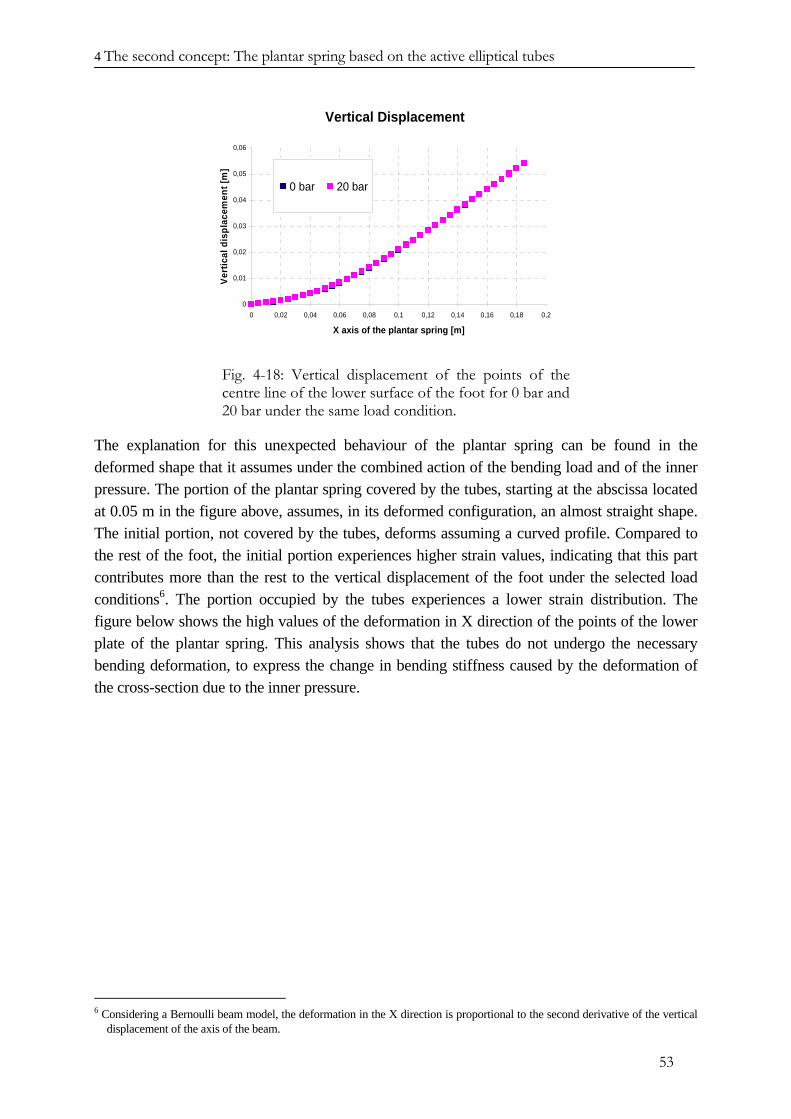
4 The second concept: The plantar spring based on the active elliptical tubes
Vertical Displacement
0
0,01
0,02
0,03
0,04
0,05
0,06
0 0,02 0,04 0,06 0,08 0,1 0,12 0,14 0,16 0,18 0,2
X axis of the plantar spring [m]
Vert
ical
dis
plac
emen
t [m
]
0 bar 20 bar
Fig. 4-18: Vertical displacement of the points of the centre line of the lower surface of the foot for 0 bar and 20 bar under the same load condition.
The explanation for this unexpected behaviour of the plantar spring can be found in the deformed shape that it assumes under the combined action of the bending load and of the inner pressure. The portion of the plantar spring covered by the tubes, starting at the abscissa located at 0.05 m in the figure above, assumes, in its deformed configuration, an almost straight shape. The initial portion, not covered by the tubes, deforms assuming a curved profile. Compared to the rest of the foot, the initial portion experiences higher strain values, indicating that this part contributes more than the rest to the vertical displacement of the foot under the selected load conditions6. The portion occupied by the tubes experiences a lower strain distribution. The figure below shows the high values of the deformation in X direction of the points of the lower plate of the plantar spring. This analysis shows that the tubes do not undergo the necessary bending deformation, to express the change in bending stiffness caused by the deformation of the cross-section due to the inner pressure.
6 Considering a Bernoulli beam model, the deformation in the X direction is proportional to the second derivative of the vertical
displacement of the axis of the beam.
53

4 The second concept: The plantar spring based on the active elliptical tubes
Fig. 4-19: Deformation in X direction of the lower surface of the passive plate.
This behaviour depends essentially on the stiffness distribution of the lower plate of the plantar spring and on the bending stiffness of the tubes.
The foot should be designed to react with a different vertical displacement of the elements of the plantar spring under the same load condition.
Keeping a constant configuration for the active tubes, the active plantar spring will be designed for a thickness distribution which stiffens the initial part of the passive lower plate and emphasises the bending deformation of the portion covered by the tubes.
The bending stiffness distribution of the modified plantar spring will differ from the optimised distribution of the passive foot given by Otto Bock. This is a necessary price to pay and could represent a severe limitation for the success of the active foot.
4.9. Optimising the thickness distribution of the lower plate
The goal in designing the lower plate of the plantar spring will be to increase the active change in bending stiffness of the new foot. The choice to design the active plantar spring according to the stiffness distribution of the passive foot respects the biomechanical behaviour of the prosthesis, but it results in ineffective performance of the active tubes. The new thickness distribution of the lower plate will be defined to increase the effectiveness of the active plantar spring.
The analysis of the previous results shows how to modify the thickness distribution of the lower plate in order to increase the performances of the active plantar spring.
Defining the thickness distribution for maximum active change in bending stiffness is an iterative process, during which the geometry of the numerical model of the lower plate is updated with the selected thickness distribution. Considering the load condition, the vertical displacement of the updated plantar spring is numerically evaluated for a zero value of inner pressure and for the maximum value of 20 bar. The corresponding value of the bending stiffness
54
4 The second concept: The plantar spring based on the active elliptical tubes
for both load conditions is determined by the definition (4.2), and the corresponding variation quantified. Based on these results and considering the mechanical behaviour of the plantar spring, with strain distribution as key factor for the design of the structure, the thickness distribution of the lower plate is updated and the change in bending stiffness recomputed.
At this stage, the thickness distribution has been designed considering the same glass fibre composite material used for the previous analysis. The maximum strain represents the quantity according to which the mechanical state of the structure under selected load conditions is defined. The maximum admissible strain of the glass fibre composite material has been assumed to be 0.01. Further, the characteristics of the adaptive foot, with the new plantar spring, may be assessed only by the patient during a walking test.
The first layout of the new plantar spring emphasises the stiffness of the initial portion of the lower plate, while the thickness of the other parts was kept unchanged, except for the terminal part where the thickness has been set at 1 mm.
The purpose of this first attempt is to verify the effectiveness of the proposed strategy irrespective, at this stage of work, of the limits and technical problem that can arise. The next steps will deal with the optimising the structure in order to match the structural requirements and to maximise the active change in bending stiffness. In the following, several configurations of the lower plate are presented and discussed.
St03
St03 represents the first attempt to define an improved thickness distribution of the lower plate. For this layout, the initial part of the plantar spring, extending from the connection with the C-spring up to the initial cross-sections of the tubes, is significantly thicker than to the same part of the plantar spring, designed to match the same stiffness distribution of the conventional plantar spring. This configuration enables a higher deformation of the portion of the foot covered by the active tubes, therefore improving the effectiveness of the active solution. However, due to the abrupt change in thickness, this configuration shows a localised high concentration of strain that could lead to delamination, or to localised crack of the composite material.
St051
This configuration of the lower part of the plantar spring represents an evolution of the St03 thickness distribution. The abrupt change in thickness of the lower plate of the former configuration causes a high strain level at the transition zone between the initial part and the portion occupied by the tubes.
A smoother thickness distribution in the critical transition zone improves the strain distribution, avoiding high strain levels that were observed in the previous layout. The new thickness distribution also shows an increased active change in bending stiffness.
55
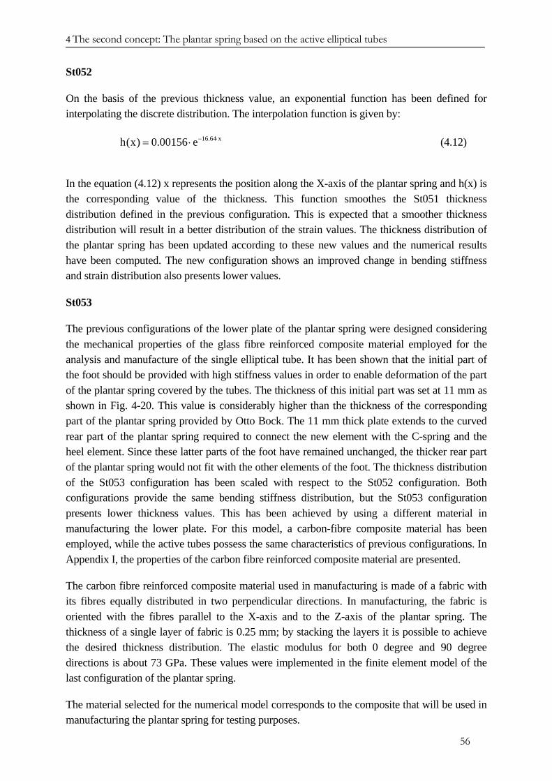
4 The second concept: The plantar spring based on the active elliptical tubes
St052
On the basis of the previous thickness value, an exponential function has been defined for interpolating the discrete distribution. The interpolation function is given by:
16.64 xh(x) 0.00156 e− ⋅= ⋅ (4.12)
In the equation (4.12) x represents the position along the X-axis of the plantar spring and h(x) is the corresponding value of the thickness. This function smoothes the St051 thickness distribution defined in the previous configuration. This is expected that a smoother thickness distribution will result in a better distribution of the strain values. The thickness distribution of the plantar spring has been updated according to these new values and the numerical results have been computed. The new configuration shows an improved change in bending stiffness and strain distribution also presents lower values.
St053
The previous configurations of the lower plate of the plantar spring were designed considering the mechanical properties of the glass fibre reinforced composite material employed for the analysis and manufacture of the single elliptical tube. It has been shown that the initial part of the foot should be provided with high stiffness values in order to enable deformation of the part of the plantar spring covered by the tubes. The thickness of this initial part was set at 11 mm as shown in Fig. 4-20. This value is considerably higher than the thickness of the corresponding part of the plantar spring provided by Otto Bock. The 11 mm thick plate extends to the curved rear part of the plantar spring required to connect the new element with the C-spring and the heel element. Since these latter parts of the foot have remained unchanged, the thicker rear part of the plantar spring would not fit with the other elements of the foot. The thickness distribution of the St053 configuration has been scaled with respect to the St052 configuration. Both configurations provide the same bending stiffness distribution, but the St053 configuration presents lower thickness values. This has been achieved by using a different material in manufacturing the lower plate. For this model, a carbon-fibre composite material has been employed, while the active tubes possess the same characteristics of previous configurations. In Appendix I, the properties of the carbon fibre reinforced composite material are presented.
The carbon fibre reinforced composite material used in manufacturing is made of a fabric with its fibres equally distributed in two perpendicular directions. In manufacturing, the fabric is oriented with the fibres parallel to the X-axis and to the Z-axis of the plantar spring. The thickness of a single layer of fabric is 0.25 mm; by stacking the layers it is possible to achieve the desired thickness distribution. The elastic modulus for both 0 degree and 90 degree directions is about 73 GPa. These values were implemented in the finite element model of the last configuration of the plantar spring.
The material selected for the numerical model corresponds to the composite that will be used in manufacturing the plantar spring for testing purposes.
56
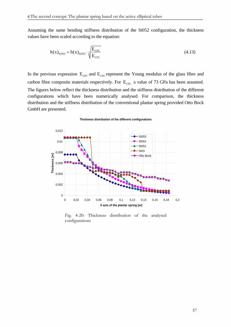
4 The second concept: The plantar spring based on the active elliptical tubes
Assuming the same bending stiffness distribution of the St052 configuration, the thickness values have been scaled according to the equation:
GFC3St053 St052CFC
Eh(x) h(x)E
= ⋅ (4.13)
In the previous expression represent the Young modulus of the glass fibre and
carbon fibre composite materials respectively. For a value of 73 GPa has been assumed.
The figures below reflect the thickness distribution and the stiffness distribution of the different configurations which have been numerically analysed. For comparison, the thickness distribution and the stiffness distribution of the conventional plantar spring provided Otto Bock GmbH are presented.
GFC CFCE and E
CFCE
Thickness distribution of the different configurations
0
0,002
0,004
0,006
0,008
0,01
0,012
0 0,02 0,04 0,06 0,08 0,1 0,12 0,14 0,16 0,18 0,2
X axis of the plantar spring [m]
Thic
knes
s [m
]
St053St052St051St03Otto Bock
Fig. 4-20: Thickness distribution of the analysed configurations
57
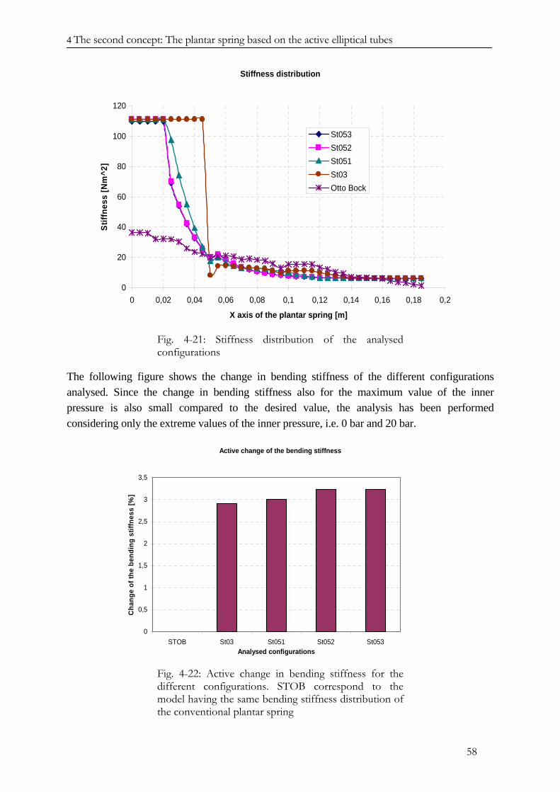
4 The second concept: The plantar spring based on the active elliptical tubes
Stiffness distribution
0
20
40
60
80
100
120
0 0,02 0,04 0,06 0,08 0,1 0,12 0,14 0,16 0,18 0,2
X axis of the plantar spring [m]
Stiff
ness
[Nm
^2]
St053St052St051St03Otto Bock
Fig. 4-21: Stiffness distribution of the analysed configurations
The following figure shows the change in bending stiffness of the different configurations analysed. Since the change in bending stiffness also for the maximum value of the inner pressure is also small compared to the desired value, the analysis has been performed considering only the extreme values of the inner pressure, i.e. 0 bar and 20 bar.
Active change of the bending stiffness
0
0,5
1
1,5
2
2,5
3
3,5
STOB St03 St051 St052 St053Analysed configurations
Cha
nge
of th
e be
ndin
g st
iffne
ss [%
]
Fig. 4-22: Active change in bending stiffness for the different configurations. STOB correspond to the model having the same bending stiffness distribution of the conventional plantar spring
58
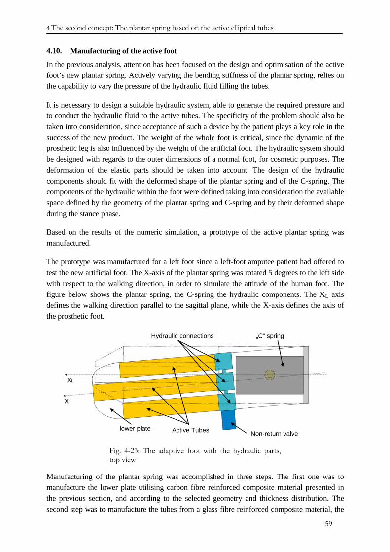
4 The second concept: The plantar spring based on the active elliptical tubes
4.10. Manufacturing of the active foot
In the previous analysis, attention has been focused on the design and optimisation of the active foot’s new plantar spring. Actively varying the bending stiffness of the plantar spring, relies on the capability to vary the pressure of the hydraulic fluid filling the tubes.
It is necessary to design a suitable hydraulic system, able to generate the required pressure and to conduct the hydraulic fluid to the active tubes. The specificity of the problem should also be taken into consideration, since acceptance of such a device by the patient plays a key role in the success of the new product. The weight of the whole foot is critical, since the dynamic of the prosthetic leg is also influenced by the weight of the artificial foot. The hydraulic system should be designed with regards to the outer dimensions of a normal foot, for cosmetic purposes. The deformation of the elastic parts should be taken into account: The design of the hydraulic components should fit with the deformed shape of the plantar spring and of the C-spring. The components of the hydraulic within the foot were defined taking into consideration the available space defined by the geometry of the plantar spring and C-spring and by their deformed shape during the stance phase.
Based on the results of the numeric simulation, a prototype of the active plantar spring was manufactured.
The prototype was manufactured for a left foot since a left-foot amputee patient had offered to test the new artificial foot. The X-axis of the plantar spring was rotated 5 degrees to the left side with respect to the walking direction, in order to simulate the attitude of the human foot. The figure below shows the plantar spring, the C-spring the hydraulic components. The XL axis defines the walking direction parallel to the sagittal plane, while the X-axis defines the axis of the prosthetic foot.
Active Tubeslower plate
Hydraulic connections „C“ spring
Non-return valve
Fig. 4-23: The adaptive foot with the hydraulic parts, top view
Manufacturing of the plantar spring was accomplished in three steps. The first one was to manufacture the lower plate utilising carbon fibre reinforced composite material presented in the previous section, and according to the selected geometry and thickness distribution. The second step was to manufacture the tubes from a glass fibre reinforced composite material, the
59
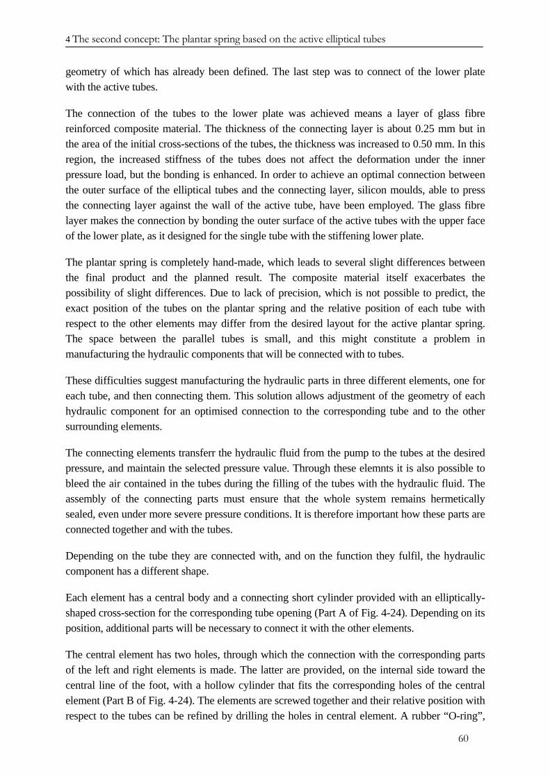
4 The second concept: The plantar spring based on the active elliptical tubes
geometry of which has already been defined. The last step was to connect of the lower plate with the active tubes.
The connection of the tubes to the lower plate was achieved means a layer of glass fibre reinforced composite material. The thickness of the connecting layer is about 0.25 mm but in the area of the initial cross-sections of the tubes, the thickness was increased to 0.50 mm. In this region, the increased stiffness of the tubes does not affect the deformation under the inner pressure load, but the bonding is enhanced. In order to achieve an optimal connection between the outer surface of the elliptical tubes and the connecting layer, silicon moulds, able to press the connecting layer against the wall of the active tube, have been employed. The glass fibre layer makes the connection by bonding the outer surface of the active tubes with the upper face of the lower plate, as it designed for the single tube with the stiffening lower plate.
The plantar spring is completely hand-made, which leads to several slight differences between the final product and the planned result. The composite material itself exacerbates the possibility of slight differences. Due to lack of precision, which is not possible to predict, the exact position of the tubes on the plantar spring and the relative position of each tube with respect to the other elements may differ from the desired layout for the active plantar spring. The space between the parallel tubes is small, and this might constitute a problem in manufacturing the hydraulic components that will be connected with to tubes.
These difficulties suggest manufacturing the hydraulic parts in three different elements, one for each tube, and then connecting them. This solution allows adjustment of the geometry of each hydraulic component for an optimised connection to the corresponding tube and to the other surrounding elements.
The connecting elements transferr the hydraulic fluid from the pump to the tubes at the desired pressure, and maintain the selected pressure value. Through these elemnts it is also possible to bleed the air contained in the tubes during the filling of the tubes with the hydraulic fluid. The assembly of the connecting parts must ensure that the whole system remains hermetically sealed, even under more severe pressure conditions. It is therefore important how these parts are connected together and with the tubes.
Depending on the tube they are connected with, and on the function they fulfil, the hydraulic component has a different shape.
Each element has a central body and a connecting short cylinder provided with an elliptically-shaped cross-section for the corresponding tube opening (Part A of Fig. 4-24). Depending on its position, additional parts will be necessary to connect it with the other elements.
The central element has two holes, through which the connection with the corresponding parts of the left and right elements is made. The latter are provided, on the internal side toward the central line of the foot, with a hollow cylinder that fits the corresponding holes of the central element (Part B of Fig. 4-24). The elements are screwed together and their relative position with respect to the tubes can be refined by drilling the holes in central element. A rubber “O-ring”,
60
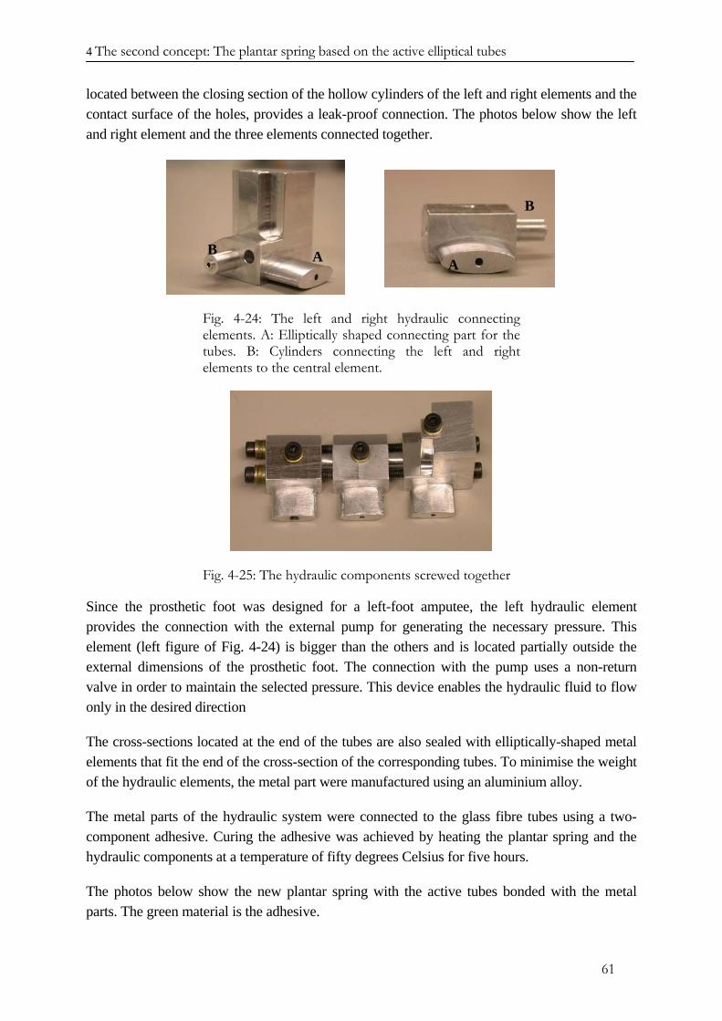
4 The second concept: The plantar spring based on the active elliptical tubes
located between the closing section of the hollow cylinders of the left and right elements and the contact surface of the holes, provides a leak-proof connection. The photos below show the left and right element and the three elements connected together.
A AB
B
A AB
B
Fig. 4-24: The left and right hydraulic connecting elements. A: Elliptically shaped connecting part for the tubes. B: Cylinders connecting the left and right elements to the central element.
Fig. 4-25: The hydraulic components screwed together
Since the prosthetic foot was designed for a left-foot amputee, the left hydraulic element provides the connection with the external pump for generating the necessary pressure. This element (left figure of Fig. 4-24) is bigger than the others and is located partially outside the external dimensions of the prosthetic foot. The connection with the pump uses a non-return valve in order to maintain the selected pressure. This device enables the hydraulic fluid to flow only in the desired direction
The cross-sections located at the end of the tubes are also sealed with elliptically-shaped metal elements that fit the end of the cross-section of the corresponding tubes. To minimise the weight of the hydraulic elements, the metal part were manufactured using an aluminium alloy.
The metal parts of the hydraulic system were connected to the glass fibre tubes using a two-component adhesive. Curing the adhesive was achieved by heating the plantar spring and the hydraulic components at a temperature of fifty degrees Celsius for five hours.
The photos below show the new plantar spring with the active tubes bonded with the metal parts. The green material is the adhesive.
61
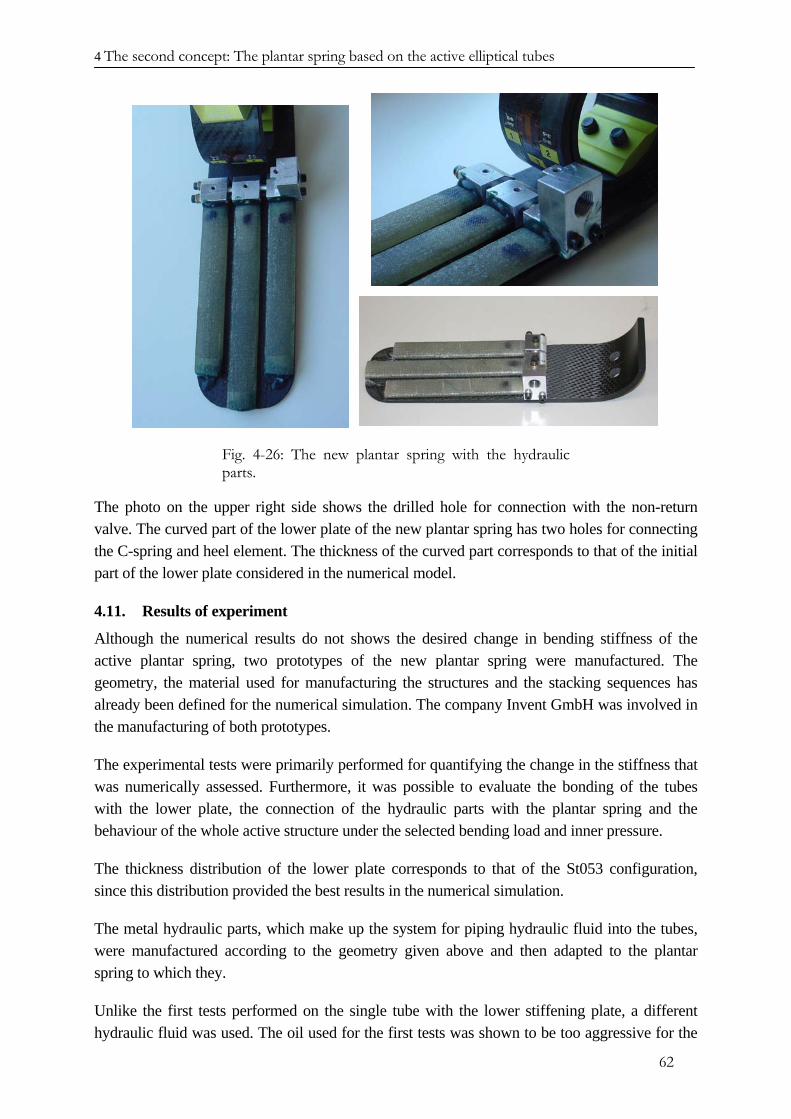
4 The second concept: The plantar spring based on the active elliptical tubes
Fig. 4-26: The new plantar spring with the hydraulic parts.
The photo on the upper right side shows the drilled hole for connection with the non-return valve. The curved part of the lower plate of the new plantar spring has two holes for connecting the C-spring and heel element. The thickness of the curved part corresponds to that of the initial part of the lower plate considered in the numerical model.
4.11. Results of experiment
Although the numerical results do not shows the desired change in bending stiffness of the active plantar spring, two prototypes of the new plantar spring were manufactured. The geometry, the material used for manufacturing the structures and the stacking sequences has already been defined for the numerical simulation. The company Invent GmbH was involved in the manufacturing of both prototypes.
The experimental tests were primarily performed for quantifying the change in the stiffness that was numerically assessed. Furthermore, it was possible to evaluate the bonding of the tubes with the lower plate, the connection of the hydraulic parts with the plantar spring and the behaviour of the whole active structure under the selected bending load and inner pressure.
The thickness distribution of the lower plate corresponds to that of the St053 configuration, since this distribution provided the best results in the numerical simulation.
The metal hydraulic parts, which make up the system for piping hydraulic fluid into the tubes, were manufactured according to the geometry given above and then adapted to the plantar spring to which they.
Unlike the first tests performed on the single tube with the lower stiffening plate, a different hydraulic fluid was used. The oil used for the first tests was shown to be too aggressive for the
62
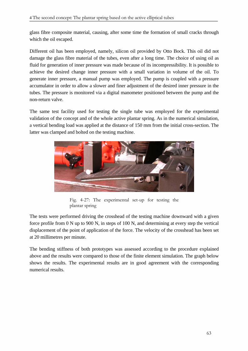
4 The second concept: The plantar spring based on the active elliptical tubes
glass fibre composite material, causing, after some time the formation of small cracks through which the oil escaped.
Different oil has been employed, namely, silicon oil provided by Otto Bock. This oil did not damage the glass fibre material of the tubes, even after a long time. The choice of using oil as fluid for generation of inner pressure was made because of its incompressibility. It is possible to achieve the desired change inner pressure with a small variation in volume of the oil. To generate inner pressure, a manual pump was employed. The pump is coupled with a pressure accumulator in order to allow a slower and finer adjustment of the desired inner pressure in the tubes. The pressure is monitored via a digital manometer positioned between the pump and the non-return valve.
The same test facility used for testing the single tube was employed for the experimental validation of the concept and of the whole active plantar spring. As in the numerical simulation, a vertical bending load was applied at the distance of 150 mm from the initial cross-section. The latter was clamped and bolted on the testing machine.
Fig. 4-27: The experimental set-up for testing the plantar spring
The tests were performed driving the crosshead of the testing machine downward with a given force profile from 0 N up to 900 N, in steps of 100 N, and determining at every step the vertical displacement of the point of application of the force. The velocity of the crosshead has been set at 20 millimetres per minute.
The bending stiffness of both prototypes was assessed according to the procedure explained above and the results were compared to those of the finite element simulation. The graph below shows the results. The experimental results are in good agreement with the corresponding numerical results.
63
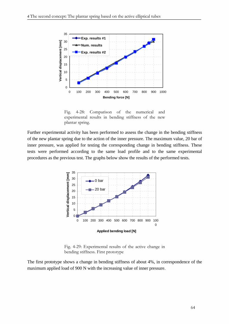
4 The second concept: The plantar spring based on the active elliptical tubes
0
5
10
15
20
25
30
35
0 100 200 300 400 500 600 700 800 900 1000
Bending force [N]
Vert
ical
dis
plac
emen
t [m
m] Exp. results #1
Num. results
Exp. results #2
Fig. 4-28: Comparison of the numerical and experimental results in bending stiffness of the new plantar spring.
Further experimental activity has been performed to assess the change in the bending stiffness of the new plantar spring due to the action of the inner pressure. The maximum value, 20 bar of inner pressure, was applied for testing the corresponding change in bending stiffness. These tests were performed according to the same load profile and to the same experimental procedures as the previous test. The graphs below show the results of the performed tests.
0
5
10
15
20
25
30
35
0 100 200 300 400 500 600 700 800 900 1000
Applied bending load [N]
Vert
ical
dis
plac
emen
t [m
m]
0 bar
20 bar
Fig. 4-29: Experimental results of the active change in bending stiffness. First prototype
The first prototype shows a change in bending stiffness of about 4%, in correspondence of the maximum applied load of 900 N with the increasing value of inner pressure.
64
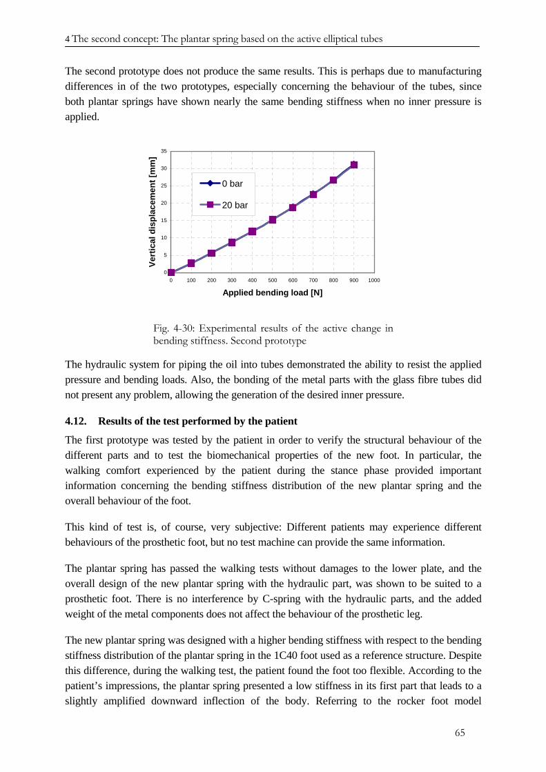
4 The second concept: The plantar spring based on the active elliptical tubes
The second prototype does not produce the same results. This is perhaps due to manufacturing differences in of the two prototypes, especially concerning the behaviour of the tubes, since both plantar springs have shown nearly the same bending stiffness when no inner pressure is applied.
0
5
10
15
20
25
30
35
0 100 200 300 400 500 600 700 800 900 1000
Applied bending load [N]
Vert
ical
dis
plac
emen
t [m
m]
0 bar
20 bar
Fig. 4-30: Experimental results of the active change in bending stiffness. Second prototype
The hydraulic system for piping the oil into tubes demonstrated the ability to resist the applied pressure and bending loads. Also, the bonding of the metal parts with the glass fibre tubes did not present any problem, allowing the generation of the desired inner pressure.
4.12. Results of the test performed by the patient
The first prototype was tested by the patient in order to verify the structural behaviour of the different parts and to test the biomechanical properties of the new foot. In particular, the walking comfort experienced by the patient during the stance phase provided important information concerning the bending stiffness distribution of the new plantar spring and the overall behaviour of the foot.
This kind of test is, of course, very subjective: Different patients may experience different behaviours of the prosthetic foot, but no test machine can provide the same information.
The plantar spring has passed the walking tests without damages to the lower plate, and the overall design of the new plantar spring with the hydraulic part, was shown to be suited to a prosthetic foot. There is no interference by C-spring with the hydraulic parts, and the added weight of the metal components does not affect the behaviour of the prosthetic leg.
The new plantar spring was designed with a higher bending stiffness with respect to the bending stiffness distribution of the plantar spring in the 1C40 foot used as a reference structure. Despite this difference, during the walking test, the patient found the foot too flexible. According to the patient’s impressions, the plantar spring presented a low stiffness in its first part that leads to a slightly amplified downward inflection of the body. Referring to the rocker foot model
65
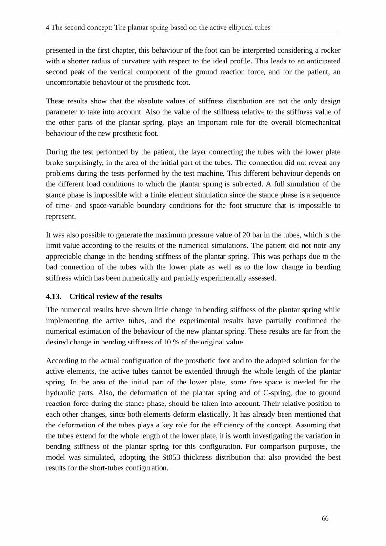
4 The second concept: The plantar spring based on the active elliptical tubes
presented in the first chapter, this behaviour of the foot can be interpreted considering a rocker with a shorter radius of curvature with respect to the ideal profile. This leads to an anticipated second peak of the vertical component of the ground reaction force, and for the patient, an uncomfortable behaviour of the prosthetic foot.
These results show that the absolute values of stiffness distribution are not the only design parameter to take into account. Also the value of the stiffness relative to the stiffness value of the other parts of the plantar spring, plays an important role for the overall biomechanical behaviour of the new prosthetic foot.
During the test performed by the patient, the layer connecting the tubes with the lower plate broke surprisingly, in the area of the initial part of the tubes. The connection did not reveal any problems during the tests performed by the test machine. This different behaviour depends on the different load conditions to which the plantar spring is subjected. A full simulation of the stance phase is impossible with a finite element simulation since the stance phase is a sequence of time- and space-variable boundary conditions for the foot structure that is impossible to represent.
It was also possible to generate the maximum pressure value of 20 bar in the tubes, which is the limit value according to the results of the numerical simulations. The patient did not note any appreciable change in the bending stiffness of the plantar spring. This was perhaps due to the bad connection of the tubes with the lower plate as well as to the low change in bending stiffness which has been numerically and partially experimentally assessed.
4.13. Critical review of the results
The numerical results have shown little change in bending stiffness of the plantar spring while implementing the active tubes, and the experimental results have partially confirmed the numerical estimation of the behaviour of the new plantar spring. These results are far from the desired change in bending stiffness of 10 % of the original value.
According to the actual configuration of the prosthetic foot and to the adopted solution for the active elements, the active tubes cannot be extended through the whole length of the plantar spring. In the area of the initial part of the lower plate, some free space is needed for the hydraulic parts. Also, the deformation of the plantar spring and of C-spring, due to ground reaction force during the stance phase, should be taken into account. Their relative position to each other changes, since both elements deform elastically. It has already been mentioned that the deformation of the tubes plays a key role for the efficiency of the concept. Assuming that the tubes extend for the whole length of the lower plate, it is worth investigating the variation in bending stiffness of the plantar spring for this configuration. For comparison purposes, the model was simulated, adopting the St053 thickness distribution that also provided the best results for the short-tubes configuration.
66
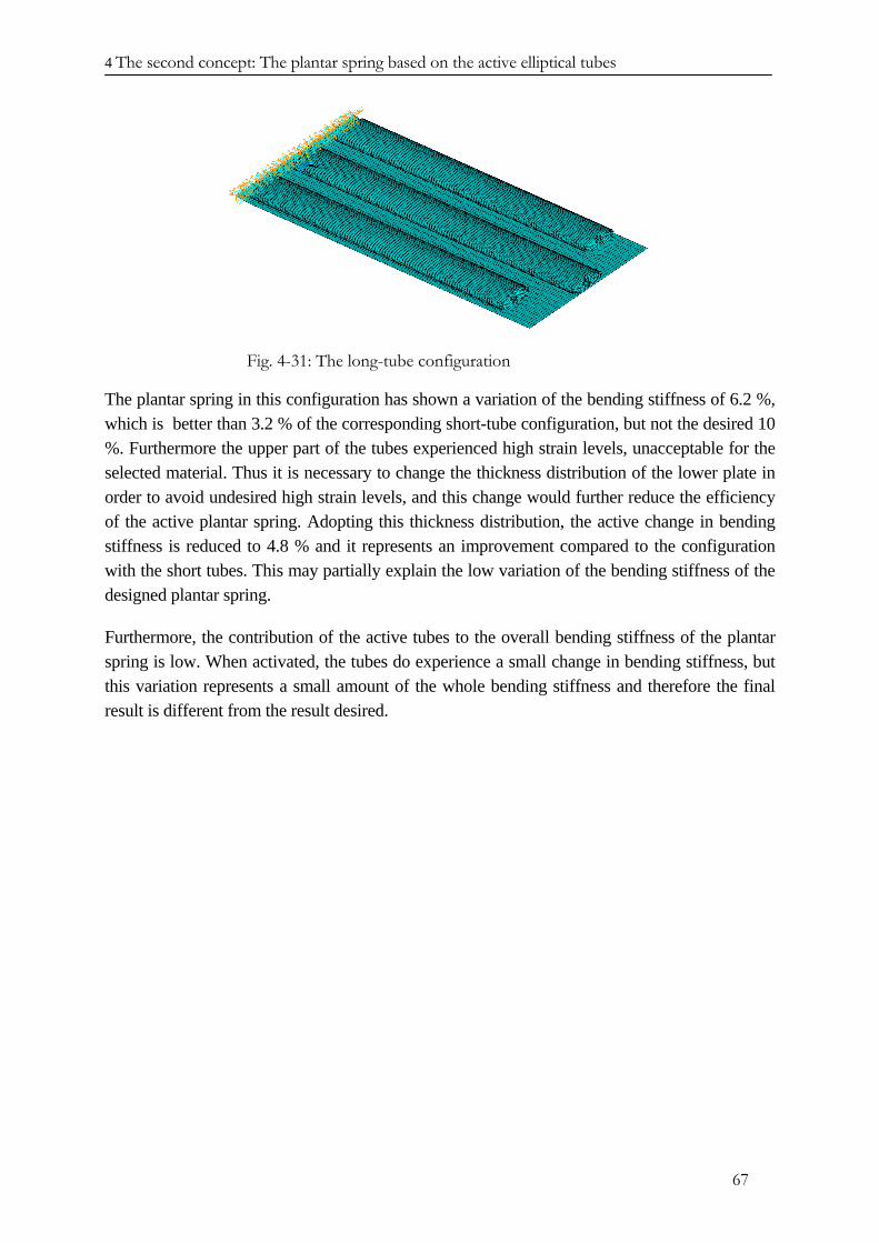
4 The second concept: The plantar spring based on the active elliptical tubes
Fig. 4-31: The long-tube configuration
The plantar spring in this configuration has shown a variation of the bending stiffness of 6.2 %, which is better than 3.2 % of the corresponding short-tube configuration, but not the desired 10 %. Furthermore the upper part of the tubes experienced high strain levels, unacceptable for the selected material. Thus it is necessary to change the thickness distribution of the lower plate in order to avoid undesired high strain levels, and this change would further reduce the efficiency of the active plantar spring. Adopting this thickness distribution, the active change in bending stiffness is reduced to 4.8 % and it represents an improvement compared to the configuration with the short tubes. This may partially explain the low variation of the bending stiffness of the designed plantar spring.
Furthermore, the contribution of the active tubes to the overall bending stiffness of the plantar spring is low. When activated, the tubes do experience a small change in bending stiffness, but this variation represents a small amount of the whole bending stiffness and therefore the final result is different from the result desired.
67
4 The second concept: The plantar spring based on the active elliptical tubes
REFERENCES CHAPTER IV
[4.1] C.M. Wayman: “Shape memory alloys”, MRS Bulletin, April 1993.
[4.2] L.F. Campanile: “Weight optimisation of hinges for light mechanism: Criteria and design aspects”, Struct. Multidisc. Optimisation, 28, 206 – 213, 2004
[4.3] B.J. de Blonk, D.C. Lagoudas: “Actuation of elastomeric rods with embedded two-way shape memory alloy actuators”, Smart Materials and Structures, 7, 1998, 771-783.
[4.4] D. Siler, K.B. Demoret: “Variable stiffness mechanism with SMA actuators”, SPIE Vol. 2721, 1996, 427-435.
[4.5] C. Santulli, S.I. Patel, G. Jeronimidis, F.J. Davis, G.R. Mitchell: “Development of smart variable stiffness actuators using polymer hydrogels”, Smart Mat. Struct. 14 2005.
[4.6] Jochen Albus: “Analytische und semi-analytische Berechnungsmethoden zur Auslegung zylindrischer Schalenstrukturen beliebiger Querschnittsform“. Ph. D. dissertation at the RWTH, Aachen.
[4.7] T. Bein: “ Der adaptive Spoiler – Entwicklung und Umsetzung einer adaptiven Profilaufdickung zur Reduktion des transsonischen Wellenwiderstandes”, Ph.D. Dissertation at the Institute for Structural Mechanic of DLR – Braunschweig, 1999.
[4.8] M. Marchetti, D. Cutolo: “Tecnologie dei materiali compositi”, editoriale ESA, 1991.
68
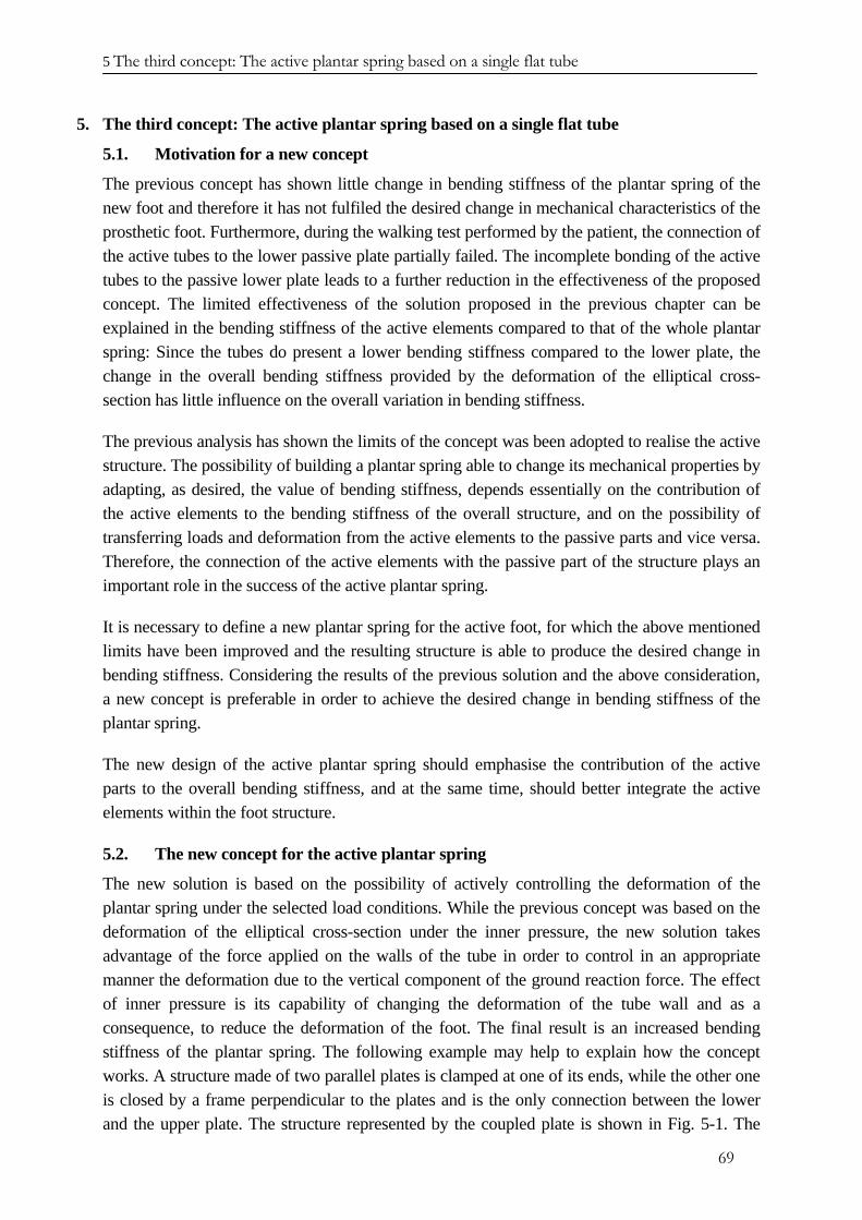
5 The third concept: The active plantar spring based on a single flat tube
69
5. The third concept: The active plantar spring based on a single flat tube
5.1. Motivation for a new concept
The previous concept has shown little change in bending stiffness of the plantar spring of the new foot and therefore it has not fulfiled the desired change in mechanical characteristics of the prosthetic foot. Furthermore, during the walking test performed by the patient, the connection of the active tubes to the lower passive plate partially failed. The incomplete bonding of the active tubes to the passive lower plate leads to a further reduction in the effectiveness of the proposed concept. The limited effectiveness of the solution proposed in the previous chapter can be explained in the bending stiffness of the active elements compared to that of the whole plantar spring: Since the tubes do present a lower bending stiffness compared to the lower plate, the change in the overall bending stiffness provided by the deformation of the elliptical cross-section has little influence on the overall variation in bending stiffness.
The previous analysis has shown the limits of the concept was been adopted to realise the active structure. The possibility of building a plantar spring able to change its mechanical properties by adapting, as desired, the value of bending stiffness, depends essentially on the contribution of the active elements to the bending stiffness of the overall structure, and on the possibility of transferring loads and deformation from the active elements to the passive parts and vice versa. Therefore, the connection of the active elements with the passive part of the structure plays an important role in the success of the active plantar spring.
It is necessary to define a new plantar spring for the active foot, for which the above mentioned limits have been improved and the resulting structure is able to produce the desired change in bending stiffness. Considering the results of the previous solution and the above consideration, a new concept is preferable in order to achieve the desired change in bending stiffness of the plantar spring.
The new design of the active plantar spring should emphasise the contribution of the active parts to the overall bending stiffness, and at the same time, should better integrate the active elements within the foot structure.
5.2. The new concept for the active plantar spring
The new solution is based on the possibility of actively controlling the deformation of the plantar spring under the selected load conditions. While the previous concept was based on the deformation of the elliptical cross-section under the inner pressure, the new solution takes advantage of the force applied on the walls of the tube in order to control in an appropriate manner the deformation due to the vertical component of the ground reaction force. The effect of inner pressure is its capability of changing the deformation of the tube wall and as a consequence, to reduce the deformation of the foot. The final result is an increased bending stiffness of the plantar spring. The following example may help to explain how the concept works. A structure made of two parallel plates is clamped at one of its ends, while the other one is closed by a frame perpendicular to the plates and is the only connection between the lower and the upper plate. The structure represented by the coupled plate is shown in Fig. 5-1. The
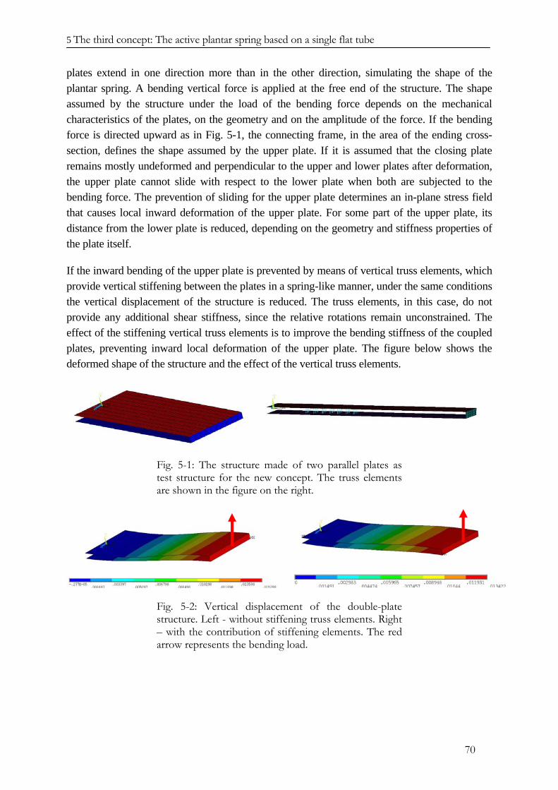
5 The third concept: The active plantar spring based on a single flat tube
70
plates extend in one direction more than in the other direction, simulating the shape of the plantar spring. A bending vertical force is applied at the free end of the structure. The shape assumed by the structure under the load of the bending force depends on the mechanical characteristics of the plates, on the geometry and on the amplitude of the force. If the bending force is directed upward as in Fig. 5-1, the connecting frame, in the area of the ending cross-section, defines the shape assumed by the upper plate. If it is assumed that the closing plate remains mostly undeformed and perpendicular to the upper and lower plates after deformation, the upper plate cannot slide with respect to the lower plate when both are subjected to the bending force. The prevention of sliding for the upper plate determines an in-plane stress field that causes local inward deformation of the upper plate. For some part of the upper plate, its distance from the lower plate is reduced, depending on the geometry and stiffness properties of the plate itself.
If the inward bending of the upper plate is prevented by means of vertical truss elements, which provide vertical stiffening between the plates in a spring-like manner, under the same conditions the vertical displacement of the structure is reduced. The truss elements, in this case, do not provide any additional shear stiffness, since the relative rotations remain unconstrained. The effect of the stiffening vertical truss elements is to improve the bending stiffness of the coupled plates, preventing inward local deformation of the upper plate. The figure below shows the deformed shape of the structure and the effect of the vertical truss elements.
Fig. 5-1: The structure made of two parallel plates as test structure for the new concept. The truss elements are shown in the figure on the right.
Fig. 5-2: Vertical displacement of the double-plate structure. Left - without stiffening truss elements. Right – with the contribution of stiffening elements. The red arrow represents the bending load.
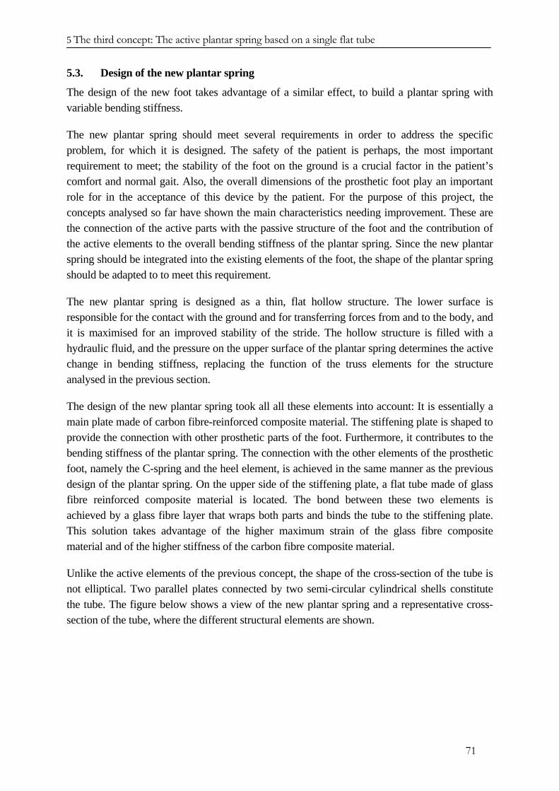
5 The third concept: The active plantar spring based on a single flat tube
71
5.3. Design of the new plantar spring
The design of the new foot takes advantage of a similar effect, to build a plantar spring with variable bending stiffness.
The new plantar spring should meet several requirements in order to address the specific problem, for which it is designed. The safety of the patient is perhaps, the most important requirement to meet; the stability of the foot on the ground is a crucial factor in the patient’s comfort and normal gait. Also, the overall dimensions of the prosthetic foot play an important role for in the acceptance of this device by the patient. For the purpose of this project, the concepts analysed so far have shown the main characteristics needing improvement. These are the connection of the active parts with the passive structure of the foot and the contribution of the active elements to the overall bending stiffness of the plantar spring. Since the new plantar spring should be integrated into the existing elements of the foot, the shape of the plantar spring should be adapted to to meet this requirement.
The new plantar spring is designed as a thin, flat hollow structure. The lower surface is responsible for the contact with the ground and for transferring forces from and to the body, and it is maximised for an improved stability of the stride. The hollow structure is filled with a hydraulic fluid, and the pressure on the upper surface of the plantar spring determines the active change in bending stiffness, replacing the function of the truss elements for the structure analysed in the previous section.
The design of the new plantar spring took all all these elements into account: It is essentially a main plate made of carbon fibre-reinforced composite material. The stiffening plate is shaped to provide the connection with other prosthetic parts of the foot. Furthermore, it contributes to the bending stiffness of the plantar spring. The connection with the other elements of the prosthetic foot, namely the C-spring and the heel element, is achieved in the same manner as the previous design of the plantar spring. On the upper side of the stiffening plate, a flat tube made of glass fibre reinforced composite material is located. The bond between these two elements is achieved by a glass fibre layer that wraps both parts and binds the tube to the stiffening plate. This solution takes advantage of the higher maximum strain of the glass fibre composite material and of the higher stiffness of the carbon fibre composite material.
Unlike the active elements of the previous concept, the shape of the cross-section of the tube is not elliptical. Two parallel plates connected by two semi-circular cylindrical shells constitute the tube. The figure below shows a view of the new plantar spring and a representative cross-section of the tube, where the different structural elements are shown.
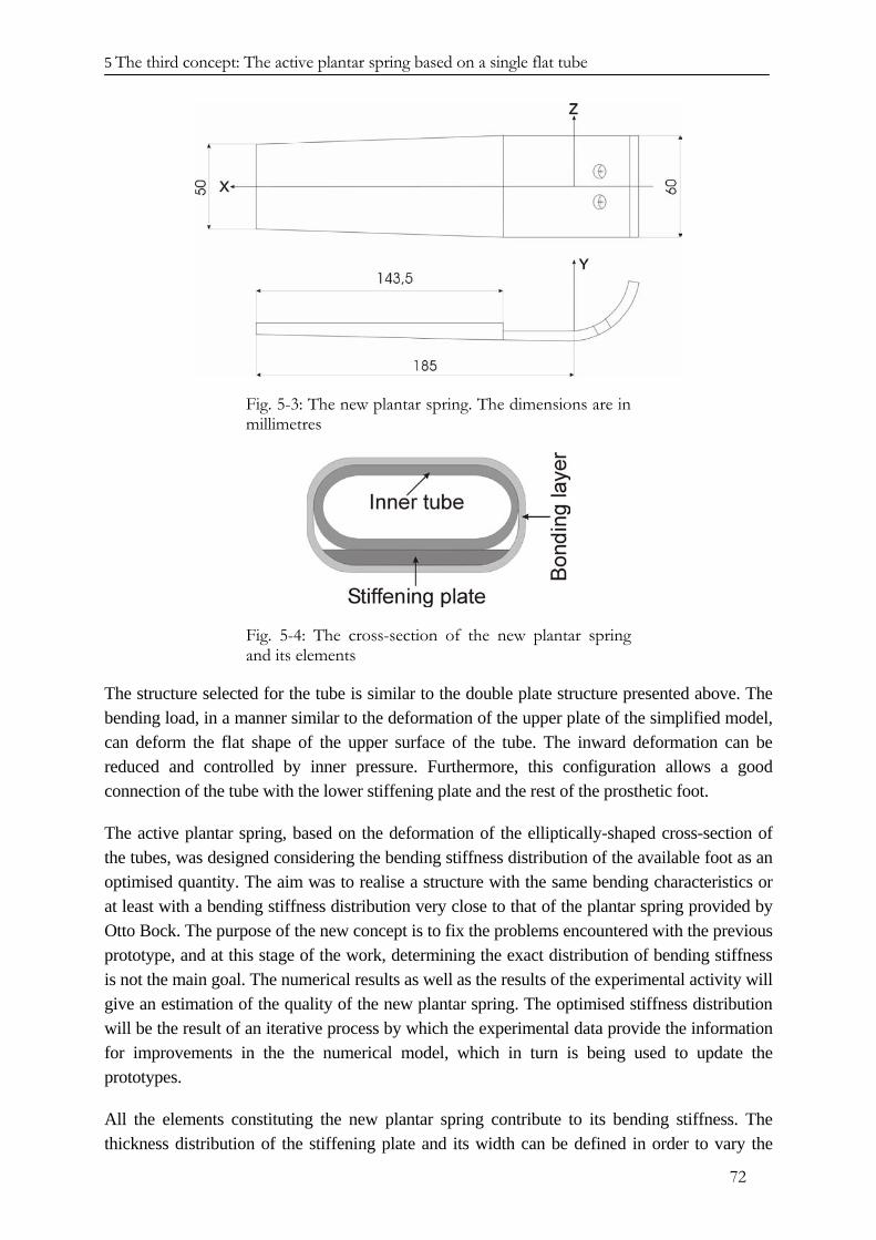
5 The third concept: The active plantar spring based on a single flat tube
72
Fig. 5-3: The new plantar spring. The dimensions are in millimetres
Fig. 5-4: The cross-section of the new plantar spring and its elements
The structure selected for the tube is similar to the double plate structure presented above. The bending load, in a manner similar to the deformation of the upper plate of the simplified model, can deform the flat shape of the upper surface of the tube. The inward deformation can be reduced and controlled by inner pressure. Furthermore, this configuration allows a good connection of the tube with the lower stiffening plate and the rest of the prosthetic foot.
The active plantar spring, based on the deformation of the elliptically-shaped cross-section of the tubes, was designed considering the bending stiffness distribution of the available foot as an optimised quantity. The aim was to realise a structure with the same bending characteristics or at least with a bending stiffness distribution very close to that of the plantar spring provided by Otto Bock. The purpose of the new concept is to fix the problems encountered with the previous prototype, and at this stage of the work, determining the exact distribution of bending stiffness is not the main goal. The numerical results as well as the results of the experimental activity will give an estimation of the quality of the new plantar spring. The optimised stiffness distribution will be the result of an iterative process by which the experimental data provide the information for improvements in the the numerical model, which in turn is being used to update the prototypes.
All the elements constituting the new plantar spring contribute to its bending stiffness. The thickness distribution of the stiffening plate and its width can be defined in order to vary the
5 The third concept: The active plantar spring based on a single flat tube
73
values of the bending stiffness. Also, the thickness of the tube and connecting layer can be selected for tuning the bending stiffness distribution, although their dimensioning depends more on the function they fulfil. The tube has a tapered shape that contributes to the variation of the bending stiffness along the X-axis of the plantar spring.
It will be seen in the following that the geometry of the stiffening plate represents the main design variable for varying the bending stiffness distribution. The thickness of the tube is defined by the values of inner pressure necessary for achieving the desired change in bending stiffness and related maximum strain. The latter represents the key facor for the design of the new foot. The connecting layer contributes to the overall thickness of the tube and bonds the tube to the upper surface of the stiffening plate.
According to the selected manufacturing procedure, the connecting layer contributes to the overall bending stiffness and to the local deformation of the upper surface of the tapered tube. Its main role is to transfer the effect of the changed shape of the tube, due to inner pressure, to the whole plantar spring and therefore determine the stiffening of the foot during the stance phase.
The design of the new plantar spring represents a compromise among three different factors. The first factor is the biomechanical characteristics that the foot possesses during the stance phase. These greatly influence the gait of the patient, and contribute to the vertical displacement of the BCOM. The second factor is the ability of the foot to actively vary its bending stiffness. The third factor is the strength of the foot structure, especially concerning maximum strain, since the previous and actual concepts are based on the active deformation of the foot structure. The geometry of the coned tube has been selected in order to maximise its upper and lower surfaces: This improves the connection with the stiffening plate and the contact with the ground.
5.4. Numerical model of the first prototype of the plantar spring
The first prototype of the new plantar spring was designed to verify the proposed concept and to analyse the mechanical behaviour of this new component of the prosthetic foot. The prototype has been implemented in a numerical model making use of the ANSYS software. A non-linear analysis was performed in order to see the effects of the deformation of the upper surface on the bending stiffness of the plantar spring. The inward bending of upper skin of the tube is a consequence of the in-plane stress on the deformed configuration of its upper surface, due to the bending load. The ANSYS element SHELL181 was used to represent the structural properties of the stiffening plate as well as the tapered tube and the connecting layer. This element provides the possibility of modelling the composite material by defining the elastic properties of the different layers and the stacking sequence of the laminate employed. The definition of the finite element model was performed taking into account the successive manufacture of the prototype necessary for experimental validation and verification of the work.
For this first simulation, the width of the stiffening plate along the X-axis of the plantar spring matches that of the coned tube. The active tube does not extend for the whole length of the lower plate. During the stance phase, the distance between the C-spring and the plantar spring is
5 The third concept: The active plantar spring based on a single flat tube
74
reduced due to the bending deformation of the latter. Therefore a certain clearance between the upper side of the initial part of the plantar spring and the C-spring is needed. Furthermore, as in the previous concept, the hydraulic system for the activation of the tube is located at the initial cross-section of the tube, close to the C-spring, and the necessary space should be provided.
The basic glass fibre layer is the same used in the model of the plantar spring with of three active tubes. It is made of a fabis of glass fibres with a 0° - 90° orientation equally distributed in both directions. The thickness of the layer is 0.25 mm. For the carbon fibre material, the basic layer is made of a fabric of carbon fibres with a 0° - 90° orientation equally distributed in both direction; its thickness is also 0.25 mm. generally using a 0° directional orientation of the X axis of the plantar spring, the glass fibre layers and the carbon fibre layers have been differently oriented. The glass fibre layers are oriented in the +/- 45° directions, while the carbon fibre layers are oriented in the 0° and 90° directions. The different orientations correspond to the different mechanical properties that have been implemented in the numerical model. Due to the woven structure, the elastic properties of the layer change depending on the direction being considered. In Appendix I, the elastic parameters of the glass fibre and carbon fibre composite materials are presented. Considering the main load condition to which the foot is subjected and the orientation of the carbon fibre and glass fibre texture, the elastic properties of each layer can be described assigning the value of the Young’s modulus for the 0° and 90° global directions. This value is the same for both orientations. For the elements making up the stiffening plate, the stacking sequences were defined, taking into account the contribution to the mechanical properties of the layers of the coned tube and of those defining the connection.
The variable thickness of the carbon fibre plate was achieved by adapting the number of carbon fibre layers to the selected thickness value, while the thickness of the wall of the tube and of the connecting layer were kept constant.
The thickness of the wall of the tube was set at 1 mm, while the thickness of the connecting layer was set at 0.50 mm. The distance between the surfaces of the flat tube is 4.00 mm.
The bending stiffness distribution of the plantar spring can be varied by changing the thickness distribution of the stiffening plate and the taper of the coned tube. The stability of the foot on the ground should be assured for each configuration of the plantar spring and therefore the taper cannot be increased too much. The contribution of the tapering to the bending stiffness is linear, while the thickness of the stiffening plate contributes with its third power. Therefore the thickness distribution is preferred for adapting the bending stiffness, in order to achieve the desired properties of the new plantar spring.
The shape and the thickness distribution of the stiffening plate are shown in the next figure. The curved part necessary for the connection with the heel element and the C-spring has the same thickness as the first thicker part of the stiffening plate and it is not represented in Fig. 5-5 showing the thickness distribution. The width of the initial part is 60 mm like the previous prototype and the whole length of the plantar spring, without the curved part necessary for the connection, is about 185 mm.
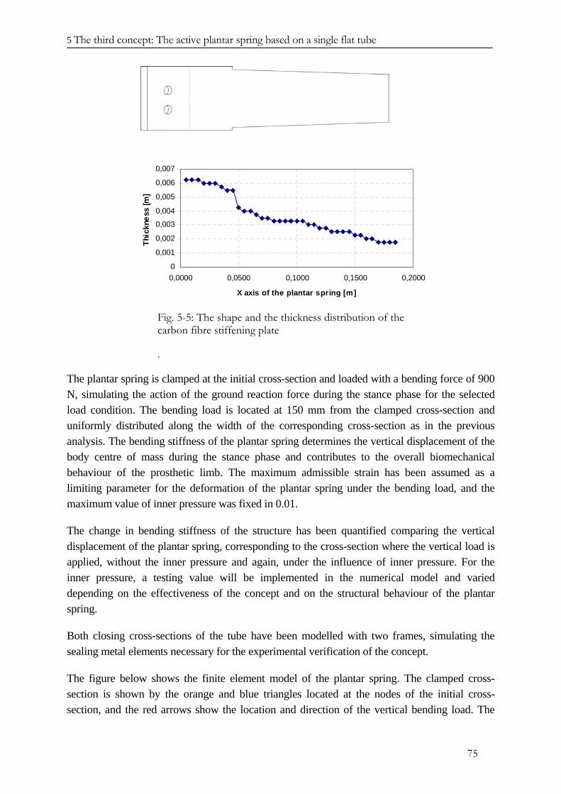
5 The third concept: The active plantar spring based on a single flat tube
75
0
0,001
0,002
0,003
0,004
0,005
0,006
0,007
0,0000 0,0500 0,1000 0,1500 0,2000
X axis of the plantar spring [m]
Thic
knes
s [m
]
Fig. 5-5: The shape and the thickness distribution of the carbon fibre stiffening plate
.
The plantar spring is clamped at the initial cross-section and loaded with a bending force of 900 N, simulating the action of the ground reaction force during the stance phase for the selected load condition. The bending load is located at 150 mm from the clamped cross-section and uniformly distributed along the width of the corresponding cross-section as in the previous analysis. The bending stiffness of the plantar spring determines the vertical displacement of the body centre of mass during the stance phase and contributes to the overall biomechanical behaviour of the prosthetic limb. The maximum admissible strain has been assumed as a limiting parameter for the deformation of the plantar spring under the bending load, and the maximum value of inner pressure was fixed in 0.01.
The change in bending stiffness of the structure has been quantified comparing the vertical displacement of the plantar spring, corresponding to the cross-section where the vertical load is applied, without the inner pressure and again, under the influence of inner pressure. For the inner pressure, a testing value will be implemented in the numerical model and varied depending on the effectiveness of the concept and on the structural behaviour of the plantar spring.
Both closing cross-sections of the tube have been modelled with two frames, simulating the sealing metal elements necessary for the experimental verification of the concept.
The figure below shows the finite element model of the plantar spring. The clamped cross-section is shown by the orange and blue triangles located at the nodes of the initial cross-section, and the red arrows show the location and direction of the vertical bending load. The
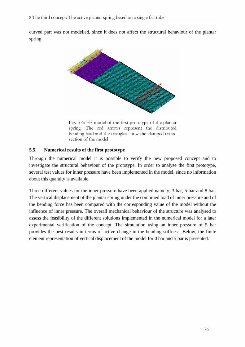
5 The third concept: The active plantar spring based on a single flat tube
76
curved part was not modelled, since it does not affect the structural behaviour of the plantar spring.
Fig. 5-6: FE model of the first prototype of the plantar spring. The red arrows represent the distributed bending load and the triangles show the clamped cross-section of the model
5.5. Numerical results of the first prototype
Through the numerical model it is possible to verify the new proposed concept and to investigate the structural behaviour of the prototype. In order to analyse the first prototype, several test values for inner pressure have been implemented in the model, since no information about this quantity is available.
Three different values for the inner pressure have been applied namely, 3 bar, 5 bar and 8 bar. The vertical displacement of the plantar spring under the combined load of inner pressure and of the bending force has been compared with the corresponding value of the model without the influence of inner pressure. The overall mechanical behaviour of the structure was analysed to assess the feasibility of the different solutions implemented in the numerical model for a later experimental verification of the concept. The simulation using an inner pressure of 5 bar provides the best results in terms of active change in the bending stiffness. Below, the finite element representation of vertical displacement of the model for 0 bar and 5 bar is presented.
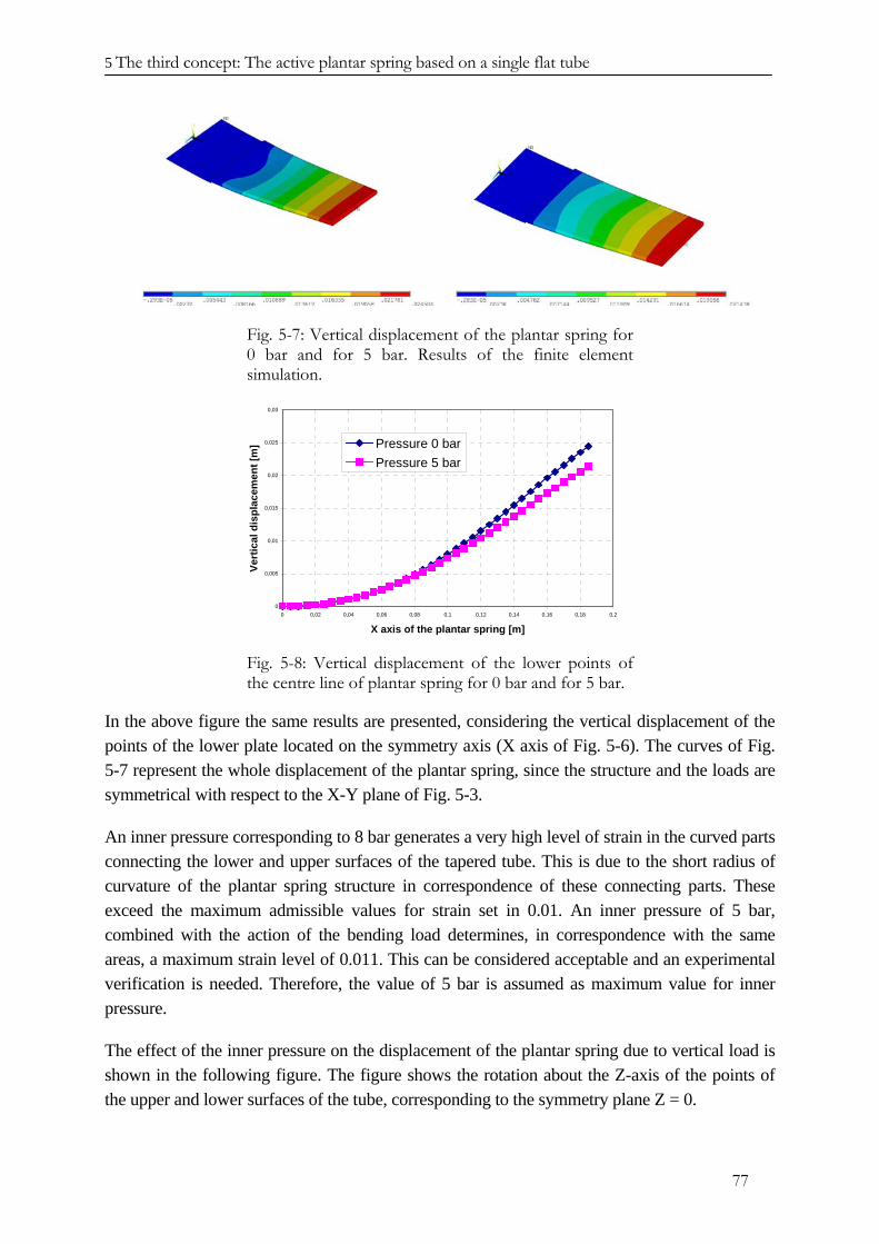
5 The third concept: The active plantar spring based on a single flat tube
77
Fig. 5-7: Vertical displacement of the plantar spring for 0 bar and for 5 bar. Results of the finite element simulation.
0
0,005
0,01
0,015
0,02
0,025
0,03
0 0,02 0,04 0,06 0,08 0,1 0,12 0,14 0,16 0,18 0,2
X axis of the plantar spring [m]
Vert
ical
dis
plac
emen
t [m
] Pressure 0 barPressure 5 bar
Fig. 5-8: Vertical displacement of the lower points of the centre line of plantar spring for 0 bar and for 5 bar.
In the above figure the same results are presented, considering the vertical displacement of the points of the lower plate located on the symmetry axis (X axis of Fig. 5-6). The curves of Fig. 5-7 represent the whole displacement of the plantar spring, since the structure and the loads are symmetrical with respect to the X-Y plane of Fig. 5-3.
An inner pressure corresponding to 8 bar generates a very high level of strain in the curved parts connecting the lower and upper surfaces of the tapered tube. This is due to the short radius of curvature of the plantar spring structure in correspondence of these connecting parts. These exceed the maximum admissible values for strain set in 0.01. An inner pressure of 5 bar, combined with the action of the bending load determines, in correspondence with the same areas, a maximum strain level of 0.011. This can be considered acceptable and an experimental verification is needed. Therefore, the value of 5 bar is assumed as maximum value for inner pressure.
The effect of the inner pressure on the displacement of the plantar spring due to vertical load is shown in the following figure. The figure shows the rotation about the Z-axis of the points of the upper and lower surfaces of the tube, corresponding to the symmetry plane Z = 0.
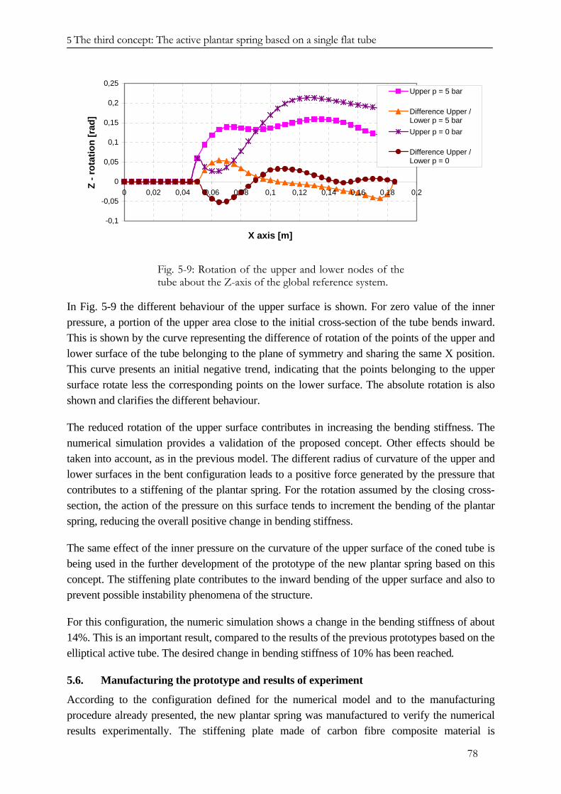
5 The third concept: The active plantar spring based on a single flat tube
78
-0,1
-0,05
0
0,05
0,1
0,15
0,2
0,25
0 0,02 0,04 0,06 0,08 0,1 0,12 0,14 0,16 0,18 0,2
X axis [m]
Z - r
otat
ion
[rad
]Upper p = 5 bar
Difference Upper /Lower p = 5 barUpper p = 0 bar
Difference Upper /Lower p = 0
Fig. 5-9: Rotation of the upper and lower nodes of the tube about the Z-axis of the global reference system.
In Fig. 5-9 the different behaviour of the upper surface is shown. For zero value of the inner pressure, a portion of the upper area close to the initial cross-section of the tube bends inward. This is shown by the curve representing the difference of rotation of the points of the upper and lower surface of the tube belonging to the plane of symmetry and sharing the same X position. This curve presents an initial negative trend, indicating that the points belonging to the upper surface rotate less the corresponding points on the lower surface. The absolute rotation is also shown and clarifies the different behaviour.
The reduced rotation of the upper surface contributes in increasing the bending stiffness. The numerical simulation provides a validation of the proposed concept. Other effects should be taken into account, as in the previous model. The different radius of curvature of the upper and lower surfaces in the bent configuration leads to a positive force generated by the pressure that contributes to a stiffening of the plantar spring. For the rotation assumed by the closing cross-section, the action of the pressure on this surface tends to increment the bending of the plantar spring, reducing the overall positive change in bending stiffness.
The same effect of the inner pressure on the curvature of the upper surface of the coned tube is being used in the further development of the prototype of the new plantar spring based on this concept. The stiffening plate contributes to the inward bending of the upper surface and also to prevent possible instability phenomena of the structure.
For this configuration, the numeric simulation shows a change in the bending stiffness of about 14%. This is an important result, compared to the results of the previous prototypes based on the elliptical active tube. The desired change in bending stiffness of 10% has been reached.
5.6. Manufacturing the prototype and results of experiment
According to the configuration defined for the numerical model and to the manufacturing procedure already presented, the new plantar spring was manufactured to verify the numerical results experimentally. The stiffening plate made of carbon fibre composite material is
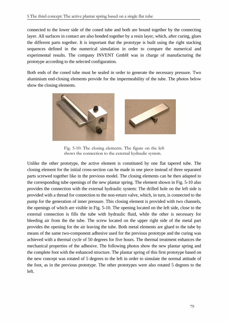
5 The third concept: The active plantar spring based on a single flat tube
79
connected to the lower side of the coned tube and both are bound together by the connecting layer. All surfaces in contact are also bonded together by a resin layer, which, after curing, glues the different parts together. It is important that the prototype is built using the right stacking sequences defined in the numerical simulation in order to compare the numerical and experimental results. The company INVENT GmbH was in charge of manufacturing the prototype according to the selected configuration.
Both ends of the coned tube must be sealed in order to generate the necessary pressure. Two aluminium end-closing elements provide for the impermeability of the tube. The photos below show the closing elements.
Fig. 5-10: The closing elements. The figure on the left shows the connection to the external hydraulic system.
Unlike the other prototype, the active element is constituted by one flat tapered tube. The closing element for the initial cross-section can be made in one piece instead of three separated parts screwed together like in the previous model. The closing elements can be then adapted to the corresponding tube openings of the new plantar spring. The element shown in Fig. 5-10 also provides the connection with the external hydraulic system: The drilled hole on the left side is provided with a thread for connection to the non-return valve, which, in turn, is connected to the pump for the generation of inner pressure. This closing element is provided with two channels, the openings of which are visible in Fig. 5-10. The opening located on the left side, close to the external connection is fills the tube with hydraulic fluid, while the other is necessary for bleeding air from the the tube. The screw located on the upper right side of the metal part provides the opening for the air leaving the tube. Both metal elements are glued to the tube by means of the same two-component adhesive used for the previous prototype and the curing was achieved with a thermal cycle of 50 degrees for five hours. The thermal treatment enhances the mechanical properties of the adhesive. The following photos show the new plantar spring and the complete foot with the enhanced structure. The plantar spring of this first prototype based on the new concept was rotated of 5 degrees to the left in order to simulate the normal attitude of the foot, as in the previous prototype. The other prototypes were also rotated 5 degrees to the left.
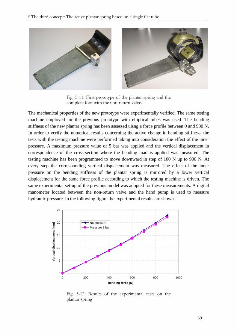
5 The third concept: The active plantar spring based on a single flat tube
80
Fig. 5-11: First prototype of the plantar spring and the complete foot with the non-return valve.
The mechanical properties of the new prototype were experimentally verified. The same testing machine employed for the previous prototype with elliptical tubes was used. The bending stiffness of the new plantar spring has been assessed uisng a force profile between 0 and 900 N. In order to verify the numerical results concerning the active change in bending stiffness, the tests with the testing machine were performed taking into consideration the effect of the inner pressure. A maximum pressure value of 5 bar was applied and the vertical displacement in correspondence of the cross-section where the bending load is applied was measured. The testing machine has been programmed to move downward in step of 100 N up to 900 N. At every step the corresponding vertical displacement was measured. The effect of the inner pressure on the bending stiffness of the plantar spring is mirrored by a lower vertical displacement for the same force profile according to which the testing machine is driven. The same experimental set-up of the previous model was adopted for these measurements. A digital manometer located between the non-return valve and the hand pump is used to measure hydraulic pressure. In the following figure the experimental results are shown.
0
5
10
15
20
25
0 200 400 600 800 1000
bending force [N]
Vert
ical
dis
plac
emen
t [m
m] No pressure
Pressure 5 bar
Fig. 5-12: Results of the experimental tests on the plantar spring
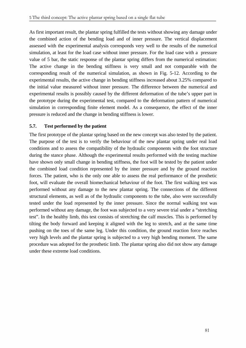
5 The third concept: The active plantar spring based on a single flat tube
81
As first important result, the plantar spring fulfilled the tests without showing any damage under the combined action of the bending load and of inner pressure. The vertical displacement assessed with the experimental analysis corresponds very well to the results of the numerical simulation, at least for the load case without inner pressure. For the load case with a pressure value of 5 bar, the static response of the plantar spring differs from the numerical estimation: The active change in the bending stiffness is very small and not comparable with the corresponding result of the numerical simulation, as shown in Fig. 5-12. According to the experimental results, the active change in bending stiffness increased about 3.25% compared to the initial value measured without inner pressure. The difference between the numerical and experimental results is possibly caused by the different deformation of the tube’s upper part in the prototype during the experimental test, compared to the deformation pattern of numerical simulation in corresponding finite element model. As a consequence, the effect of the inner pressure is reduced and the change in bending stiffness is lower.
5.7. Test performed by the patient
The first prototype of the plantar spring based on the new concept was also tested by the patient. The purpose of the test is to verify the behaviour of the new plantar spring under real load conditions and to assess the compatibility of the hydraulic components with the foot structure during the stance phase. Although the experimental results performed with the testing machine have shown only small change in bending stiffness, the foot will be tested by the patient under the combined load condition represented by the inner pressure and by the ground reaction forces. The patient, who is the only one able to assess the real performance of the prosthetic foot, will evaluate the overall biomechanical behaviour of the foot. The first walking test was performed without any damage to the new plantar spring. The connections of the different structural elements, as well as of the hydraulic components to the tube, also were successfully tested under the load represented by the inner pressure. Since the normal walking test was performed without any damage, the foot was subjected to a very severe trial under a “stretching test”. In the healthy limb, this test consists of stretching the calf muscles. This is performed by tilting the body forward and keeping it aligned with the leg to stretch, and at the same time pushing on the toes of the same leg. Under this condition, the ground reaction force reaches very high levels and the plantar spring is subjected to a very high bending moment. The same procedure was adopted for the prosthetic limb. The plantar spring also did not show any damage under these extreme load conditions.
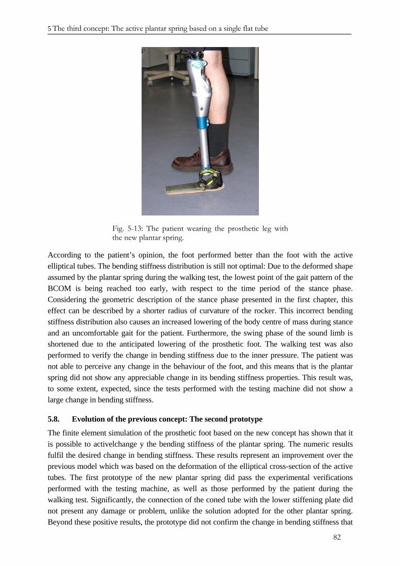
5 The third concept: The active plantar spring based on a single flat tube
82
Fig. 5-13: The patient wearing the prosthetic leg with the new plantar spring.
According to the patient’s opinion, the foot performed better than the foot with the active elliptical tubes. The bending stiffness distribution is still not optimal: Due to the deformed shape assumed by the plantar spring during the walking test, the lowest point of the gait pattern of the BCOM is being reached too early, with respect to the time period of the stance phase. Considering the geometric description of the stance phase presented in the first chapter, this effect can be described by a shorter radius of curvature of the rocker. This incorrect bending stiffness distribution also causes an increased lowering of the body centre of mass during stance and an uncomfortable gait for the patient. Furthermore, the swing phase of the sound limb is shortened due to the anticipated lowering of the prosthetic foot. The walking test was also performed to verify the change in bending stiffness due to the inner pressure. The patient was not able to perceive any change in the behaviour of the foot, and this means that is the plantar spring did not show any appreciable change in its bending stiffness properties. This result was, to some extent, expected, since the tests performed with the testing machine did not show a large change in bending stiffness.
5.8. Evolution of the previous concept: The second prototype
The finite element simulation of the prosthetic foot based on the new concept has shown that it is possible to activelchange y the bending stiffness of the plantar spring. The numeric results fulfil the desired change in bending stiffness. These results represent an improvement over the previous model which was based on the deformation of the elliptical cross-section of the active tubes. The first prototype of the new plantar spring did pass the experimental verifications performed with the testing machine, as well as those performed by the patient during the walking test. Significantly, the connection of the coned tube with the lower stiffening plate did not present any damage or problem, unlike the solution adopted for the other plantar spring. Beyond these positive results, the prototype did not confirm the change in bending stiffness that
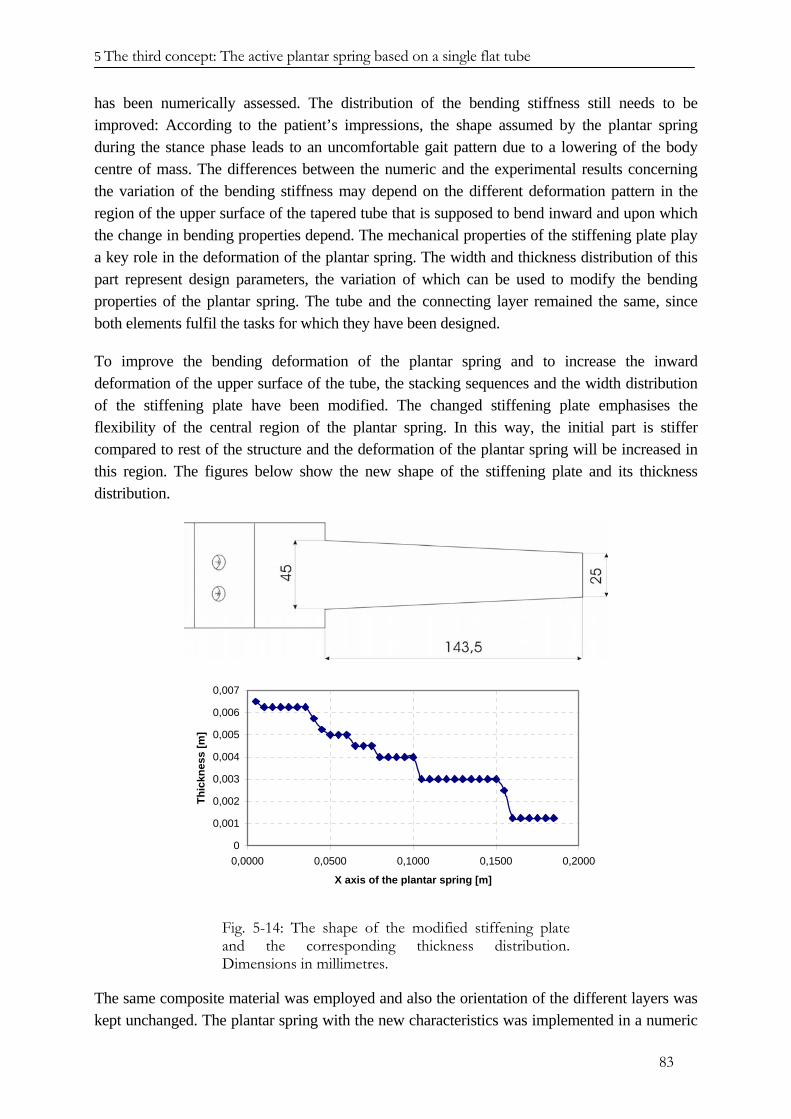
5 The third concept: The active plantar spring based on a single flat tube
83
has been numerically assessed. The distribution of the bending stiffness still needs to be improved: According to the patient’s impressions, the shape assumed by the plantar spring during the stance phase leads to an uncomfortable gait pattern due to a lowering of the body centre of mass. The differences between the numeric and the experimental results concerning the variation of the bending stiffness may depend on the different deformation pattern in the region of the upper surface of the tapered tube that is supposed to bend inward and upon which the change in bending properties depend. The mechanical properties of the stiffening plate play a key role in the deformation of the plantar spring. The width and thickness distribution of this part represent design parameters, the variation of which can be used to modify the bending properties of the plantar spring. The tube and the connecting layer remained the same, since both elements fulfil the tasks for which they have been designed.
To improve the bending deformation of the plantar spring and to increase the inward deformation of the upper surface of the tube, the stacking sequences and the width distribution of the stiffening plate have been modified. The changed stiffening plate emphasises the flexibility of the central region of the plantar spring. In this way, the initial part is stiffer compared to rest of the structure and the deformation of the plantar spring will be increased in this region. The figures below show the new shape of the stiffening plate and its thickness distribution.
0
0,001
0,002
0,003
0,004
0,005
0,006
0,007
0,0000 0,0500 0,1000 0,1500 0,2000
X axis of the plantar spring [m]
Thic
knes
s [m
]
Fig. 5-14: The shape of the modified stiffening plate and the corresponding thickness distribution. Dimensions in millimetres.
The same composite material was employed and also the orientation of the different layers was kept unchanged. The plantar spring with the new characteristics was implemented in a numeric
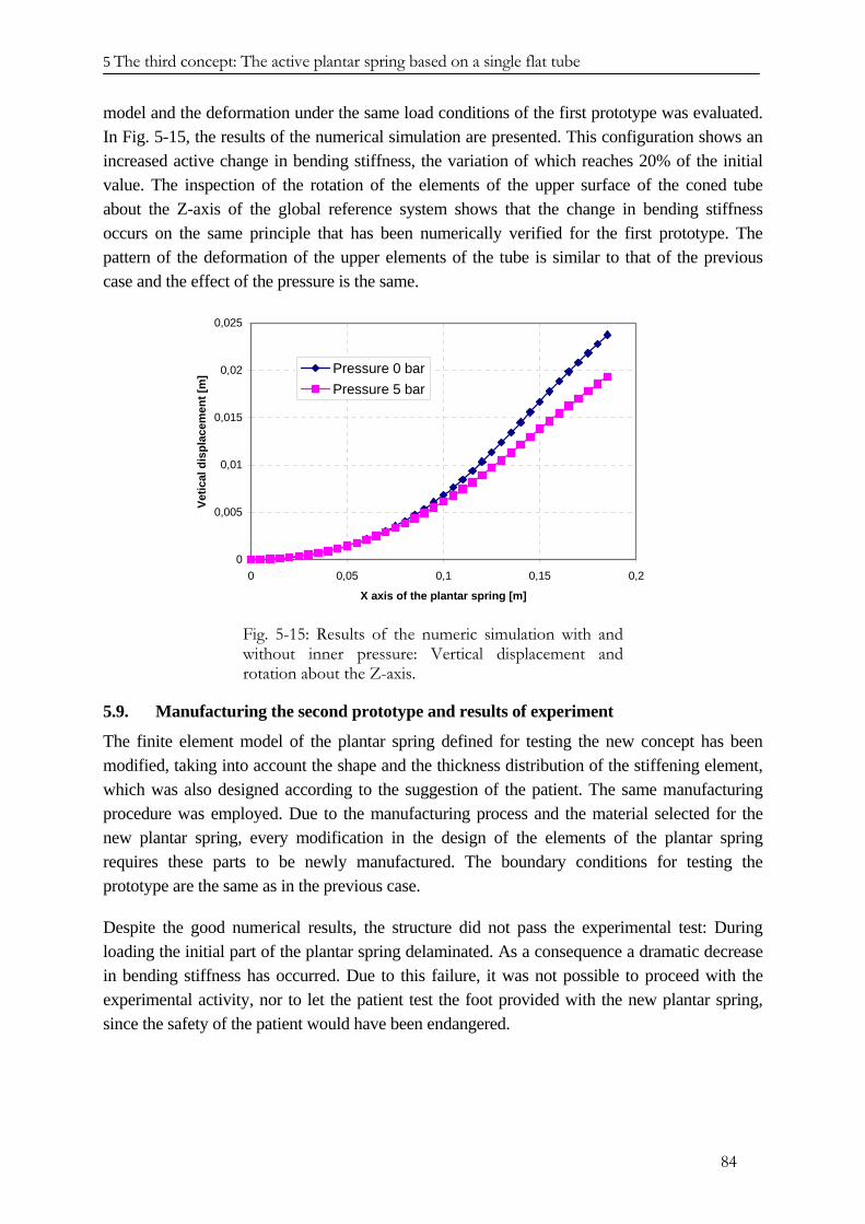
5 The third concept: The active plantar spring based on a single flat tube
84
model and the deformation under the same load conditions of the first prototype was evaluated. In Fig. 5-15, the results of the numerical simulation are presented. This configuration shows an increased active change in bending stiffness, the variation of which reaches 20% of the initial value. The inspection of the rotation of the elements of the upper surface of the coned tube about the Z-axis of the global reference system shows that the change in bending stiffness occurs on the same principle that has been numerically verified for the first prototype. The pattern of the deformation of the upper elements of the tube is similar to that of the previous case and the effect of the pressure is the same.
0
0,005
0,01
0,015
0,02
0,025
0 0,05 0,1 0,15 0,2
X axis of the plantar spring [m]
Vetic
al d
ispl
acem
ent [
m] Pressure 0 bar
Pressure 5 bar
Fig. 5-15: Results of the numeric simulation with and without inner pressure: Vertical displacement and rotation about the Z-axis.
5.9. Manufacturing the second prototype and results of experiment
The finite element model of the plantar spring defined for testing the new concept has been modified, taking into account the shape and the thickness distribution of the stiffening element, which was also designed according to the suggestion of the patient. The same manufacturing procedure was employed. Due to the manufacturing process and the material selected for the new plantar spring, every modification in the design of the elements of the plantar spring requires these parts to be newly manufactured. The boundary conditions for testing the prototype are the same as in the previous case.
Despite the good numerical results, the structure did not pass the experimental test: During loading the initial part of the plantar spring delaminated. As a consequence a dramatic decrease in bending stiffness has occurred. Due to this failure, it was not possible to proceed with the experimental activity, nor to let the patient test the foot provided with the new plantar spring, since the safety of the patient would have been endangered.
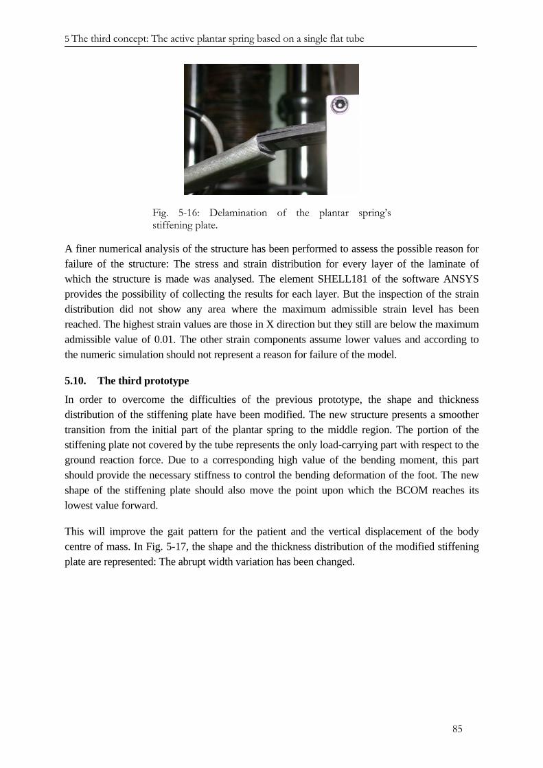
5 The third concept: The active plantar spring based on a single flat tube
85
Fig. 5-16: Delamination of the plantar spring’s stiffening plate.
A finer numerical analysis of the structure has been performed to assess the possible reason for failure of the structure: The stress and strain distribution for every layer of the laminate of which the structure is made was analysed. The element SHELL181 of the software ANSYS provides the possibility of collecting the results for each layer. But the inspection of the strain distribution did not show any area where the maximum admissible strain level has been reached. The highest strain values are those in X direction but they still are below the maximum admissible value of 0.01. The other strain components assume lower values and according to the numeric simulation should not represent a reason for failure of the model.
5.10. The third prototype
In order to overcome the difficulties of the previous prototype, the shape and thickness distribution of the stiffening plate have been modified. The new structure presents a smoother transition from the initial part of the plantar spring to the middle region. The portion of the stiffening plate not covered by the tube represents the only load-carrying part with respect to the ground reaction force. Due to a corresponding high value of the bending moment, this part should provide the necessary stiffness to control the bending deformation of the foot. The new shape of the stiffening plate should also move the point upon which the BCOM reaches its lowest value forward.
This will improve the gait pattern for the patient and the vertical displacement of the body centre of mass. In Fig. 5-17, the shape and the thickness distribution of the modified stiffening plate are represented: The abrupt width variation has been changed.
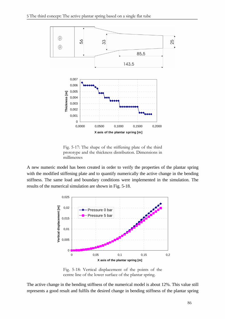
5 The third concept: The active plantar spring based on a single flat tube
86
0
0,001
0,002
0,003
0,004
0,005
0,006
0,007
0,0000 0,0500 0,1000 0,1500 0,2000
X axis of the plantar spring [m]
Thic
knes
s [m
]
Fig. 5-17: The shape of the stiffening plate of the third prototype and the thickness distribution. Dimensions in millimetres
A new numeric model has been created in order to verify the properties of the plantar spring with the modified stiffening plate and to quantify numerically the active change in the bending stiffness. The same load and boundary conditions were implemented in the simulation. The results of the numerical simulation are shown in Fig. 5-18.
0
0,005
0,01
0,015
0,02
0,025
0 0,05 0,1 0,15 0,2
X axis of the plantar spring [m]
Vert
ical
dis
plac
emen
t [m
]
Pressure 0 barPressure 5 bar
Fig. 5-18: Vertical displacement of the points of the centre line of the lower surface of the plantar spring.
The active change in the bending stiffness of the numerical model is about 12%. This value still represents a good result and fulfils the desired change in bending stiffness of the plantar spring
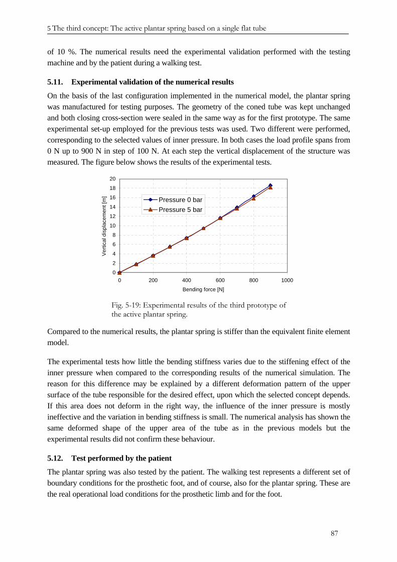
5 The third concept: The active plantar spring based on a single flat tube
87
of 10 %. The numerical results need the experimental validation performed with the testing machine and by the patient during a walking test.
5.11. Experimental validation of the numerical results
On the basis of the last configuration implemented in the numerical model, the plantar spring was manufactured for testing purposes. The geometry of the coned tube was kept unchanged and both closing cross-section were sealed in the same way as for the first prototype. The same experimental set-up employed for the previous tests was used. Two different were performed, corresponding to the selected values of inner pressure. In both cases the load profile spans from 0 N up to 900 N in step of 100 N. At each step the vertical displacement of the structure was measured. The figure below shows the results of the experimental tests.
0
2
4
6
8
10
12
14
16
18
20
0 200 400 600 800 1000
Bending force [N]
Ver
tical
dis
plac
emen
t [m
] Pressure 0 barPressure 5 bar
Fig. 5-19: Experimental results of the third prototype of the active plantar spring.
Compared to the numerical results, the plantar spring is stiffer than the equivalent finite element model.
The experimental tests how little the bending stiffness varies due to the stiffening effect of the inner pressure when compared to the corresponding results of the numerical simulation. The reason for this difference may be explained by a different deformation pattern of the upper surface of the tube responsible for the desired effect, upon which the selected concept depends. If this area does not deform in the right way, the influence of the inner pressure is mostly ineffective and the variation in bending stiffness is small. The numerical analysis has shown the same deformed shape of the upper area of the tube as in the previous models but the experimental results did not confirm these behaviour.
5.12. Test performed by the patient
The plantar spring was also tested by the patient. The walking test represents a different set of boundary conditions for the prosthetic foot, and of course, also for the plantar spring. These are the real operational load conditions for the prosthetic limb and for the foot.
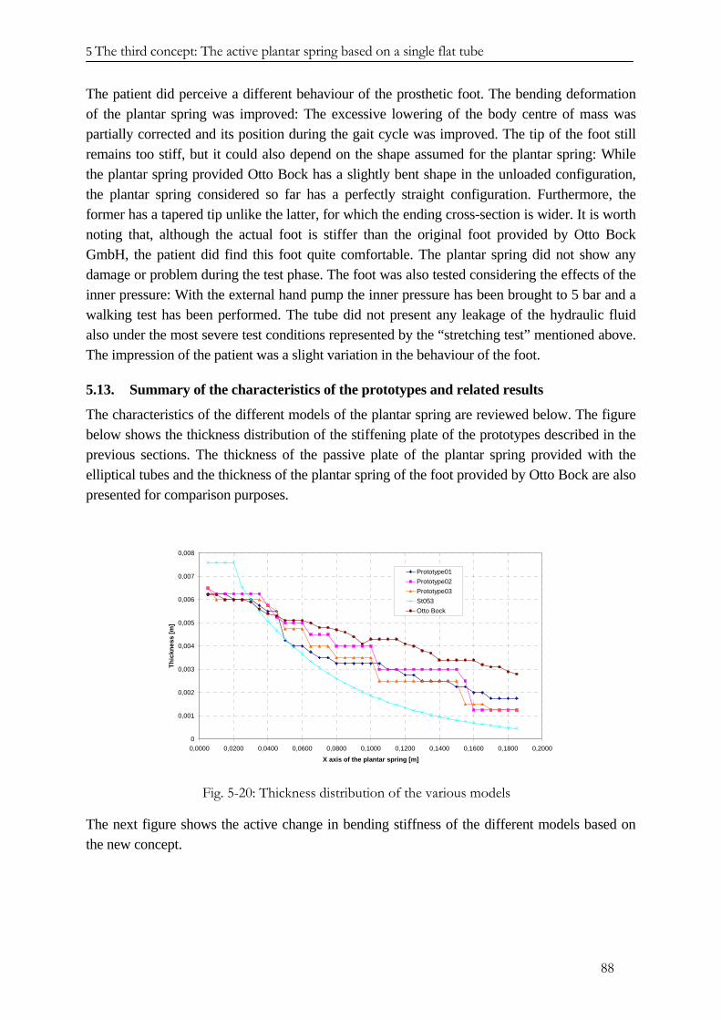
5 The third concept: The active plantar spring based on a single flat tube
88
The patient did perceive a different behaviour of the prosthetic foot. The bending deformation of the plantar spring was improved: The excessive lowering of the body centre of mass was partially corrected and its position during the gait cycle was improved. The tip of the foot still remains too stiff, but it could also depend on the shape assumed for the plantar spring: While the plantar spring provided Otto Bock has a slightly bent shape in the unloaded configuration, the plantar spring considered so far has a perfectly straight configuration. Furthermore, the former has a tapered tip unlike the latter, for which the ending cross-section is wider. It is worth noting that, although the actual foot is stiffer than the original foot provided by Otto Bock GmbH, the patient did find this foot quite comfortable. The plantar spring did not show any damage or problem during the test phase. The foot was also tested considering the effects of the inner pressure: With the external hand pump the inner pressure has been brought to 5 bar and a walking test has been performed. The tube did not present any leakage of the hydraulic fluid also under the most severe test conditions represented by the “stretching test” mentioned above. The impression of the patient was a slight variation in the behaviour of the foot.
5.13. Summary of the characteristics of the prototypes and related results
The characteristics of the different models of the plantar spring are reviewed below. The figure below shows the thickness distribution of the stiffening plate of the prototypes described in the previous sections. The thickness of the passive plate of the plantar spring provided with the elliptical tubes and the thickness of the plantar spring of the foot provided by Otto Bock are also presented for comparison purposes.
0
0,001
0,002
0,003
0,004
0,005
0,006
0,007
0,008
0,0000 0,0200 0,0400 0,0600 0,0800 0,1000 0,1200 0,1400 0,1600 0,1800 0,2000
X axis of the plantar spring [m]
Thic
knes
s [m
]
Prototype01Prototype02Prototype03St053Otto Bock
Fig. 5-20: Thickness distribution of the various models
The next figure shows the active change in bending stiffness of the different models based on the new concept.
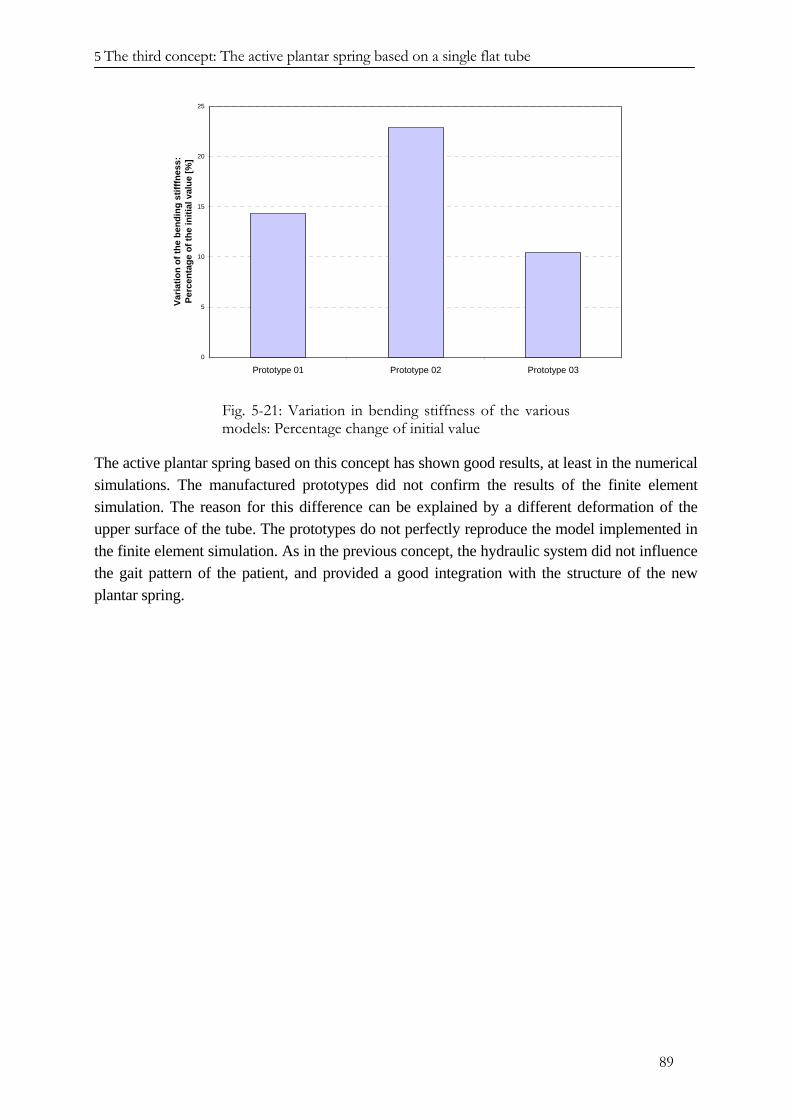
5 The third concept: The active plantar spring based on a single flat tube
89
0
5
10
15
20
25
Prototype 01 Prototype 02 Prototype 03
Varia
tion
of th
e be
ndin
g st
ifffn
ess:
Perc
enta
ge o
f the
initi
al v
alue
[%]
Fig. 5-21: Variation in bending stiffness of the various models: Percentage change of initial value
The active plantar spring based on this concept has shown good results, at least in the numerical simulations. The manufactured prototypes did not confirm the results of the finite element simulation. The reason for this difference can be explained by a different deformation of the upper surface of the tube. The prototypes do not perfectly reproduce the model implemented in the finite element simulation. As in the previous concept, the hydraulic system did not influence the gait pattern of the patient, and provided a good integration with the structure of the new plantar spring.
5 The third concept: The active plantar spring based on a single flat tube
90
REFERENCES CHAPTER V
[5.1] V.V. Novozilov: “Thin shell theory”, P. Noordhoof LTD, Groningen; The Netherlands, 1964.
[5.2] H. Mollmann: “Introduction to the theory of thin shells”, John Wiley & Sons, 1981.
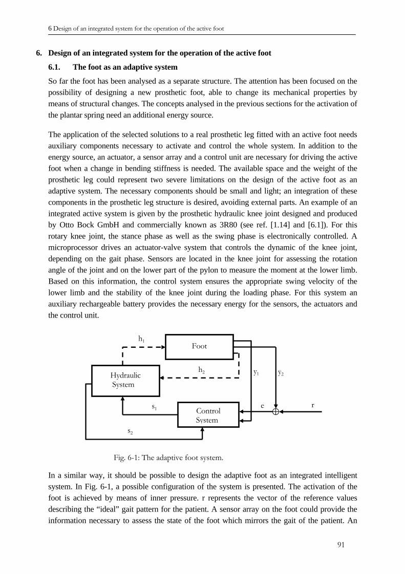
6 Design of an integrated system for the operation of the active foot
6. Design of an integrated system for the operation of the active foot
6.1. The foot as an adaptive system
Control System
Hydraulic System
Footh1
h2 y1 y2
r es1
s2
So far the foot has been analysed as a separate structure. The attention has been focused on the possibility of designing a new prosthetic foot, able to change its mechanical properties by means of structural changes. The concepts analysed in the previous sections for the activation of the plantar spring need an additional energy source.
The application of the selected solutions to a real prosthetic leg fitted with an active foot needs auxiliary components necessary to activate and control the whole system. In addition to the energy source, an actuator, a sensor array and a control unit are necessary for driving the active foot when a change in bending stiffness is needed. The available space and the weight of the prosthetic leg could represent two severe limitations on the design of the active foot as an adaptive system. The necessary components should be small and light; an integration of these components in the prosthetic leg structure is desired, avoiding external parts. An example of an integrated active system is given by the prosthetic hydraulic knee joint designed and produced by Otto Bock GmbH and commercially known as 3R80 (see ref. [1.14] and [6.1]). For this rotary knee joint, the stance phase as well as the swing phase is electronically controlled. A microprocessor drives an actuator-valve system that controls the dynamic of the knee joint, depending on the gait phase. Sensors are located in the knee joint for assessing the rotation angle of the joint and on the lower part of the pylon to measure the moment at the lower limb. Based on this information, the control system ensures the appropriate swing velocity of the lower limb and the stability of the knee joint during the loading phase. For this system an auxiliary rechargeable battery provides the necessary energy for the sensors, the actuators and the control unit.
Fig. 6-1: The adaptive foot system.
In a similar way, it should be possible to design the adaptive foot as an integrated intelligent system. In Fig. 6-1, a possible configuration of the system is presented. The activation of the foot is achieved by means of inner pressure. r represents the vector of the reference values describing the “ideal” gait pattern for the patient. A sensor array on the foot could provide the information necessary to assess the state of the foot which mirrors the gait of the patient. An
91
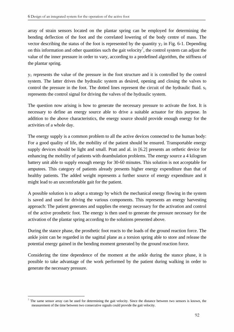
6 Design of an integrated system for the operation of the active foot
array of strain sensors located on the plantar spring can be employed for determining the bending deflection of the foot and the correlated lowering of the body centre of mass. The vector describing the status of the foot is represented by the quantity y2 in Fig. 6-1. Depending on this information and other quantities such the gait velocity7, the control system can adjust the value of the inner pressure in order to vary, according to a predefined algorithm, the stiffness of the plantar spring.
y1 represents the value of the pressure in the foot structure and it is controlled by the control system. The latter drives the hydraulic system as desired, opening and closing the valves to control the pressure in the foot. The dotted lines represent the circuit of the hydraulic fluid. s1 represents the control signal for driving the valves of the hydraulic system.
The question now arising is how to generate the necessary pressure to activate the foot. It is necessary to define an energy source able to drive a suitable actuator for this purpose. In addition to the above characteristics, the energy source should provide enough energy for the activities of a whole day.
The energy supply is a common problem to all the active devices connected to the human body: For a good quality of life, the mobility of the patient should be ensured. Transportable energy supply devices should be light and small. Pratt and al. in [6.2] presents an orthetic device for enhancing the mobility of patients with deambulation problems. The energy source a 4 kilogram battery unit able to supply enough energy for 30-60 minutes. This solution is not acceptable for amputees. This category of patients already presents higher energy expenditure than that of healthy patients. The added weight represents a further source of energy expenditure and it might lead to an uncomfortable gait for the patient.
A possible solution is to adopt a strategy by which the mechanical energy flowing in the system is saved and used for driving the various components. This represents an energy harvesting approach: The patient generates and supplies the energy necessary for the activation and control of the active prosthetic foot. The energy is then used to generate the pressure necessary for the activation of the plantar spring according to the solutions presented above.
During the stance phase, the prosthetic foot reacts to the loads of the ground reaction force. The ankle joint can be regarded in the sagittal plane as a torsion spring able to store and release the potential energy gained in the bending moment generated by the ground reaction force.
Considering the time dependence of the moment at the ankle during the stance phase, it is possible to take advantage of the work performed by the patient during walking in order to generate the necessary pressure.
7 The same sensor array can be used for determining the gait velocity. Since the distance between two sensors is known, the
measurement of the time between two consecutive signals could provide the gait velocity.
92
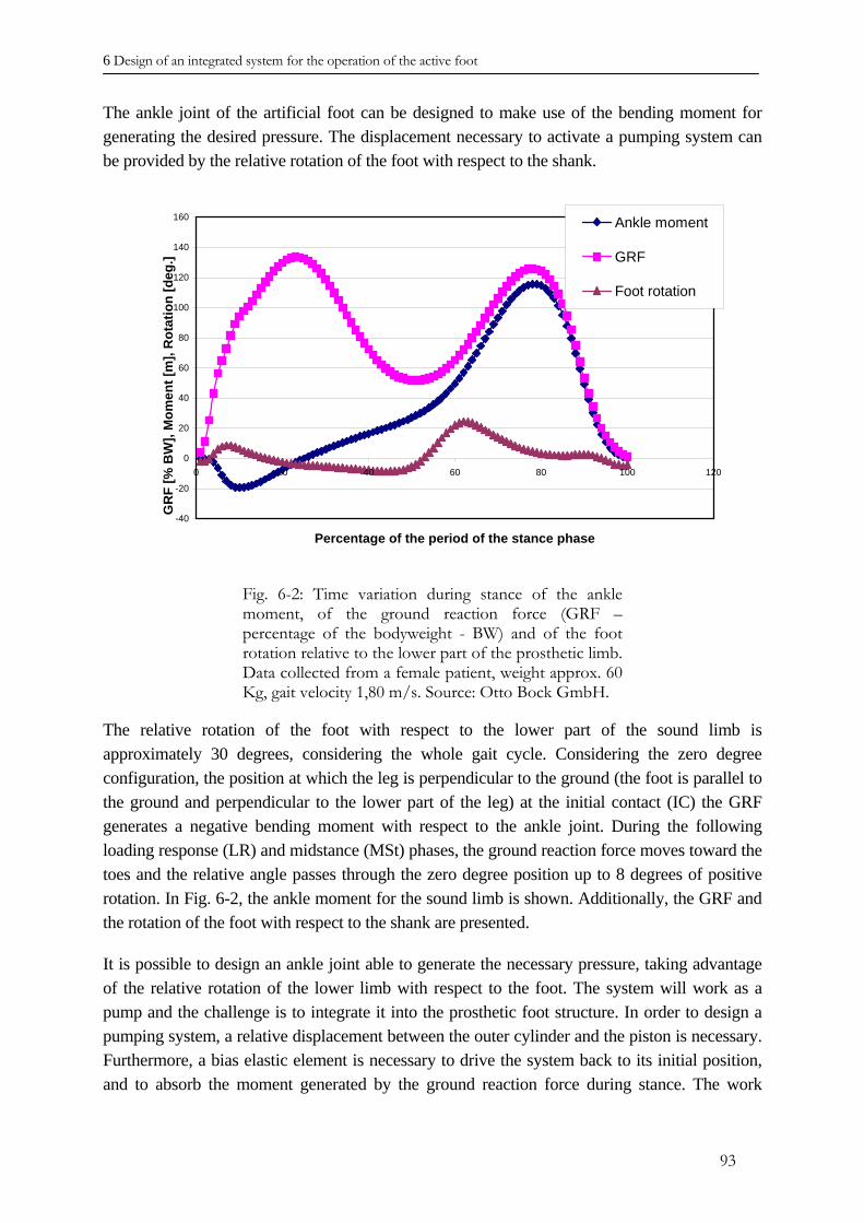
6 Design of an integrated system for the operation of the active foot
The ankle joint of the artificial foot can be designed to make use of the bending moment for generating the desired pressure. The displacement necessary to activate a pumping system can be provided by the relative rotation of the foot with respect to the shank.
-40
-20
0
20
40
60
80
100
120
140
160
0 20 40 60 80 100 120
Percentage of the period of the stance phase
GR
F [%
BW
], M
omen
t [m
], R
otat
ion
[deg
.]
Ankle moment
GRF
Foot rotation
Fig. 6-2: Time variation during stance of the ankle moment, of the ground reaction force (GRF – percentage of the bodyweight - BW) and of the foot rotation relative to the lower part of the prosthetic limb. Data collected from a female patient, weight approx. 60 Kg, gait velocity 1,80 m/s. Source: Otto Bock GmbH.
The relative rotation of the foot with respect to the lower part of the sound limb is approximately 30 degrees, considering the whole gait cycle. Considering the zero degree configuration, the position at which the leg is perpendicular to the ground (the foot is parallel to the ground and perpendicular to the lower part of the leg) at the initial contact (IC) the GRF generates a negative bending moment with respect to the ankle joint. During the following loading response (LR) and midstance (MSt) phases, the ground reaction force moves toward the toes and the relative angle passes through the zero degree position up to 8 degrees of positive rotation. In Fig. 6-2, the ankle moment for the sound limb is shown. Additionally, the GRF and the rotation of the foot with respect to the shank are presented.
It is possible to design an ankle joint able to generate the necessary pressure, taking advantage of the relative rotation of the lower limb with respect to the foot. The system will work as a pump and the challenge is to integrate it into the prosthetic foot structure. In order to design a pumping system, a relative displacement between the outer cylinder and the piston is necessary. Furthermore, a bias elastic element is necessary to drive the system back to its initial position, and to absorb the moment generated by the ground reaction force during stance. The work
93
6 Design of an integrated system for the operation of the active foot
performed by the ankle moment will then be partially converted in elastic energy and the rest used for generating the desired pressure.
6.2. Design of the pumping system
The main elements of the system able to generate the pressure to the activate the tubes have been brefly mentioned in previous chapters. Generation of pressure is defined by the relative displacement of a cylinder with respect to a piston. Since the system is not continuously activated, at every step, the piston or the cylinder should be brought back to the initial position. Elastic elements are included in the design of this device as bias-elements, able to initialise the system. They also provide the necessary stiffness for a comfortable and smooth rotation of the foot with respect to the lower part of the prosthetic limb. Beside these components, other elements are necessary, as shown in Fig. 6-3. The springs K1 and K2 represent the stiffening elements of the ankle joint, replacing the function of the torsion spring. The spring KR controls the displacement of the piston of the pressure accumulator, the function of which is to store the right amount of fluid at the right pressure value to activate the foot. A tank supplies the cylinder with fluid and receives the fluid from the foot when the pressure value is decreased. The valve V1 is a non-return valve connecting the cylinder with the pressure accumulator, while the valves V2 and V3 are driven by the controller and adjust the pressure in the active elements of the foot. As already mentioned, the moment at the ankle provides the driving force for displacing the cylinder with respect to the piston. Considering a reference system moving with the foot, the moment due to the GRF determines the rotation of the shank about the fixed point O as depicted in Fig. 6-3. The position ξ of the piston is controlled by the combined action of the pressure and of the spring K2. The displacement x of the cylinder depends on the length of the lever arm and on the angle of rotation of the lower part of the prosthetic leg with respect to the foot. ϕ
K1 K2
Tank
KR
FootV1
V2
V3
X
ξ
Cylinder Pressure accumulator
O
ϕ
V4
XR
L
Fig. 6-3: The components of the system for pressure generation.
94
6 Design of an integrated system for the operation of the active foot
The displacement x of the cylinder differs from the displacement ξ of the piston. This difference generates the volume change upon which the generation of the pressure for the hydraulic fluid depends. The displacement x of the cylinder can be considered assigned and defined as the product of the length L and the angle of rotation ϕ of the lever arm about the fixed point O, the unknown quantity is represented by the displacement ξ of the piston.
The displacement x of the cylinder is directly connected to the motion of the patient; the possibility of controlling the upper value of the pressure should be independent from the walking cycle, since at every step the system is activated and pressure is increased.
The function of the spring K2 is to switch the system off when the desired maximum pressure has been reached. Depending on the value of the stiffness K2, when the maximum value of the pressure has been reached, the displacement ξ of the piston matches the displacement x of the cylinder and no further increase in pressure occurs. Since it is not possible to switch the patient off, the system stops itself when the desired value of the pressure has been reached. This solution avoids an additional circuit connecting the tank to the cylinder for the flow of the hydraulic fluid.
It is now necessary to define the equations describing the time evolution of the quantities of interest. The purpose of the system is to provide the right amount of hydraulic fluid at the right pressure to activate the foot.
Three phases of the system operation can be defined. In the following, these three phases are explained and the corresponding changes in the related quantities defined.
Phase I
Let us consider the arbitrary i-th step performed by the patient. The values of the corresponding quantities describing the state of the system were defined in the previous (i-1)-th step. At the beginning of the i-th step, the cylinder occupies the position corresponding to the value x = 0 of the quantity describing its position. When the shank rotates to the right, the cylinder moves together with the shank, since they are rigidly connected. The non-return valve V1, located between the cylinder and the pressure accumulator, opens only when the pressure on the side of the cylinder is higher than the pressure on the side of the pressure accumulator. At the beginning of the i-th step, the value of the pressure in the cylinder is zero, then the cylinder moves, pushing spring K2 and causes an increase in the pressure value. The reaction force brought about by the compression of the spring K2 defines the amount of pressure in the cylinder. Until valve V1 is opened, the displacement ξ of the spring K2 matches the displacement x of the cylinder, since the hydraulic fluid can be considered incompressible. When the spring has been shortened by the quantity i 1−ξ , the pressure in the cylinder has
reached the value i 1p − of the fluid in the pressure accumulator. A further increment in the displacement x causes the valve V1 to open, and the hydraulic fluid moves from the cylinder to the pressure accumulator.
95
6 Design of an integrated system for the operation of the active foot
Phase II
When the non-return valve V1 opens, a volume change corresponding to the increase in the pressure occurs. The displacement of the cylinder is larger than the displacement of the piston, since the latter moves compressing the spring K
ix iξ
2. The fluid flows from the cylinder to the pressure accumulator until the displacement of the cylinder has reached its maximum value
and the system stops. maxx
Phase III
When the displacement of the cylinder reaches its maximum value and the artificial leg
begins the unloading phase, preceding the swing phase, the cylinder is brought back to the starting position by the loaded springs K
maxx
1 and K2. At every step the phases described above are repeated. During the driving back phase, the non-return valve V4 opens and the cylinder is filled with new fluid coming from the tank. Due to the friction of the moving parts and the drag generated by fluid, the damping for a smooth rearward rotation of the foot is provided.
After several steps, the displacement ξ of the piston of the cylinder at the end of the Phase I described above equals the maximum displacement of the cylinder. From this point, no
increase in pressure will occur during subsequent steps of the patient as long as the pressure in the pressure accumulator remains constant. The exact number of steps, after which no further pressure increase is possible, is one of the quantities to determine, depending on the stiffness K
maxx
2, KR and on the preload applied to the pressure accumulator piston.
It is necessary to define equations which are able to calculate the changes in the values describing the system. The time variation in these valus depends on the characteristics of the system and on the number of steps takes by the patient. The description of the system and the quantification of the variables of interest will yield the necessary information to decide whether the possibility of generating hydraulic pressure through this concept is compatible with the biomechanical characteristics of the prosthetic leg and patient’s gait.
The description of the system was done neglecting all the possible losses due to friction of moving parts and fluid viscosity. The equations describe the system when all the variables have reached a stationary value. Basically, the conservation of the fluid moving through the system and the equilibrium of the pressures provide the necessary conditions for identifying the quantities of the system.
6.3. The equation describing the system
In the following, the equations of the system are defined. The equations identify the value of the different quantities at the end of each step during Phase II. With this information, it is possible to estimate the performance of the system. The other two phases will be introduced as conditions for the system behaviour, according to the physics of the problem. The requirements of the system are listed below prioritised by purpose.
• Appropriate amount of fluid at the correct pressure.
96
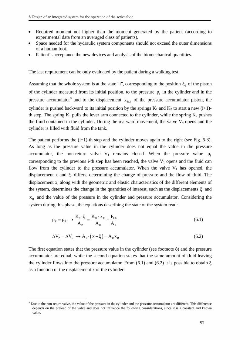
6 Design of an integrated system for the operation of the active foot
• Required moment not higher than the moment generated by the patient (according to experimental data from an averaged class of patients).
• Space needed for the hydraulic system components should not exceed the outer dimensions of a human foot.
• Patient’s acceptance the new devices and analysis of the biomechanical quantities.
The last requirement can be only evaluated by the patient during a walking test.
Assuming that the whole system is at the state “i”, corresponding to the position of the piston
of the cylinder measured from its initial position, to the pressure iξ
ip in the cylinder and in the pressure accumulator8 and to the displacement of the pressure accumulator piston, the
cylinder is pushed backward to its initial position by the springs KR ,ix
1 and K2 to start a new (i+1)-th step. The spring K1 pulls the lever arm connected to the cylinder, while the spring K2 pushes the fluid contained in the cylinder. During the rearward movement, the valve V4 opens and the cylinder is filled with fluid from the tank.
The patient performs the (i+1)-th step and the cylinder moves again to the right (see Fig. 6-3). As long as the pressure value in the cylinder does not equal the value in the pressure accumulator, the non-return valve V1 remains closed. When the pressure value ip corresponding to the previous i-th step has been reached, the valve V1 opens and the fluid can flow from the cylinder to the pressure accumulator. When the valve V1 has opened, the displacement x and differs, determining the change of pressure and the flow of fluid. The displacement x, along with the geometric and elastic characteristics of the different elements of the system, determines the change in the quantities of interest, such as the displacements
ξ
ξ and
and the value of the pressure in the cylinder and pressure accumulator. Considering the system during this phase, the equations describing the state of the system read:
Rx
R 02 R RZ R
Z R
FK K xp pA A
⋅ ξ ⋅= → = +
RA
R
(6.1)
( )Z R Z RV V A x A x∆ = ∆ → ⋅ − ξ = (6.2)
The first equation states that the pressure value in the cylinder (see footnote 8) and the pressure accumulator are equal, while the second equation states that the same amount of fluid leaving the cylinder flows into the pressure accumulator. From (6.1) and (6.2) it is possible to obtain ξ as a function of the displacement x of the cylinder:
8 Due to the non-return valve, the value of the pressure in the cylinder and the pressure accumulator are different. This difference
depends on the preload of the valve and does not influence the following considerations, since it is a constant and known value.
97
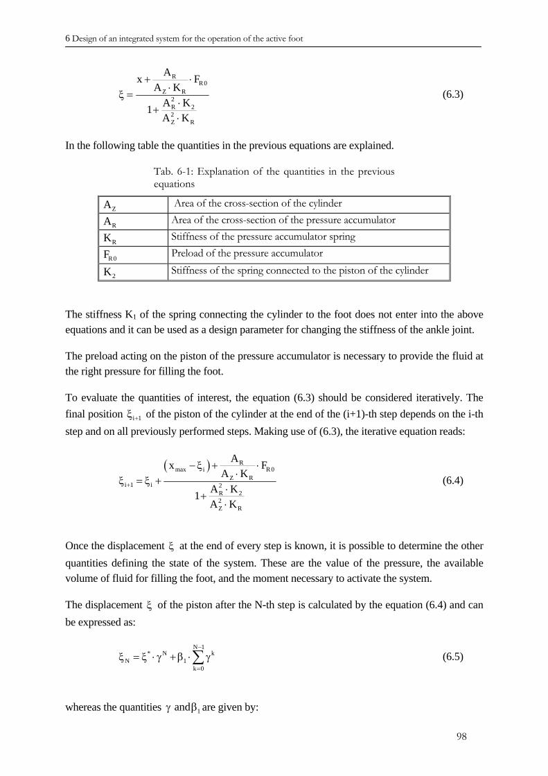
6 Design of an integrated system for the operation of the active foot
RR0
Z R2R 22Z R
Ax FA K
A K1A K
+ ⋅⋅
ξ =⋅
+⋅
(6.3)
In the following table the quantities in the previous equations are explained.
Tab. 6-1: Explanation of the quantities in the previous equations
ZA Area of the cross-section of the cylinder
RA Area of the cross-section of the pressure accumulator
RK Stiffness of the pressure accumulator spring
R0F Preload of the pressure accumulator
2K Stiffness of the spring connected to the piston of the cylinder
The stiffness K1 of the spring connecting the cylinder to the foot does not enter into the above equations and it can be used as a design parameter for changing the stiffness of the ankle joint.
The preload acting on the piston of the pressure accumulator is necessary to provide the fluid at the right pressure for filling the foot.
To evaluate the quantities of interest, the equation (6.3) should be considered iteratively. The final position of the piston of the cylinder at the end of the (i+1)-th step depends on the i-th step and on all previously performed steps. Making use of (6.3), the iterative equation reads:
i 1+ξ
( ) Rmax i R0
Z Ri 1 i 2
R 22Z R
Ax FA K
A K1A K
+
− ξ + ⋅⋅
ξ = ξ +⋅
+⋅
(6.4)
Once the displacement ξ at the end of every step is known, it is possible to determine the other quantities defining the state of the system. These are the value of the pressure, the available volume of fluid for filling the foot, and the moment necessary to activate the system.
The displacement of the piston after the N-th step is calculated by the equation (6.4) and can be expressed as:
ξ
N 1* N k
N 1k 0
−
=
ξ = ξ ⋅ γ + β ⋅ γ∑ (6.5)
whereas the quantities are given by: 1andγ β
98
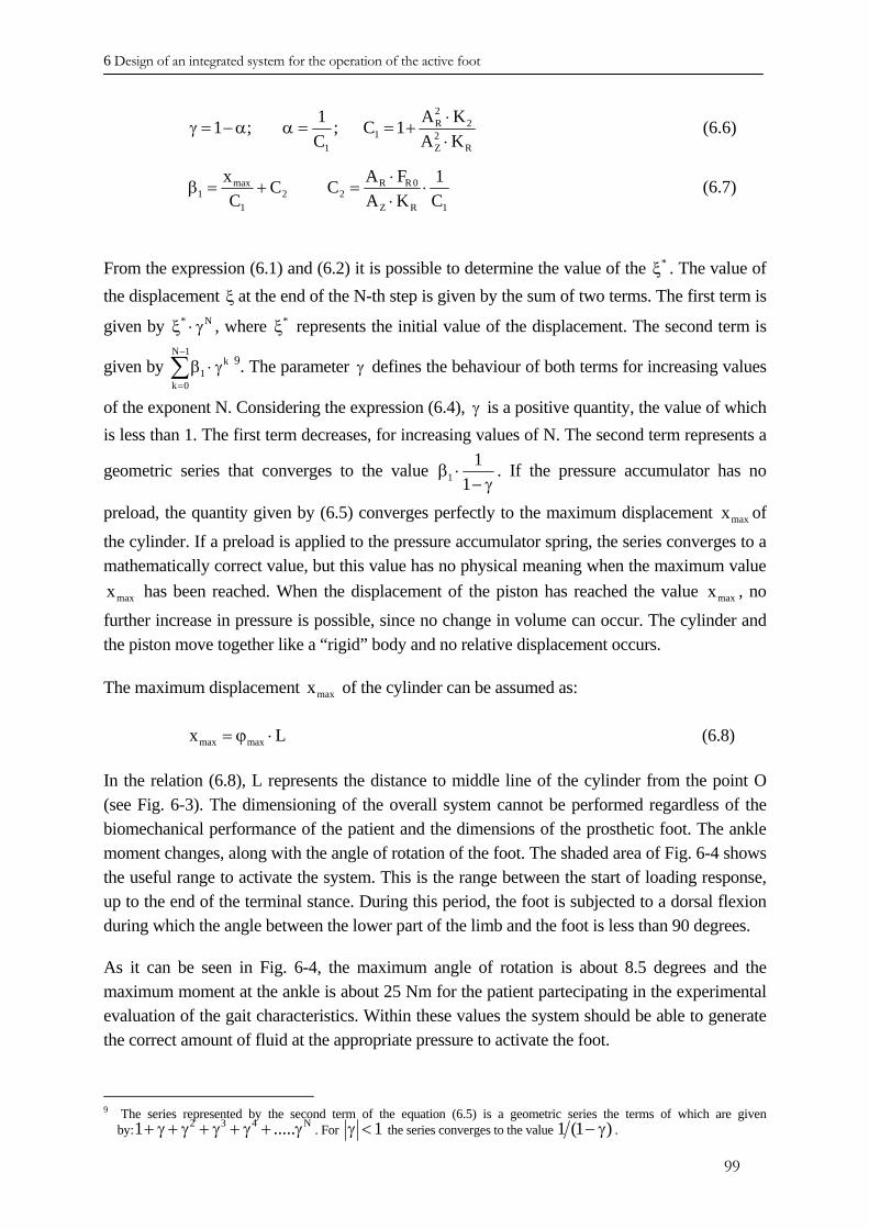
6 Design of an integrated system for the operation of the active foot
2R 2
1 21 Z
1 A1 ; ; C 1C A R
KK
⋅γ = − α α = = +
⋅ (6.6)
max R R 01 2 2
1 Z
x AC CC A R 1
F 1K C
⋅β = + = ⋅
⋅ (6.7)
From the expression (6.1) and (6.2) it is possible to determine the value of the . The value of the displacement ξ at the end of the N-th step is given by the sum of two terms. The first term is
given by , where represents the initial value of the displacement. The second term is
given by 9
*ξ
* Nξ ⋅ γ *ξN 1
kγ1k 0
−
=
β ⋅∑ . The parameter defines the behaviour of both terms for increasing values
of the exponent N. Considering the expression (6.4), is a positive quantity, the value of which is less than 1. The first term decreases, for increasing values of N. The second term represents a
geometric series that converges to the value
γ
γ
11
1β ⋅
− γ. If the pressure accumulator has no
preload, the quantity given by (6.5) converges perfectly to the maximum displacement f
the cylinder. If a preload is applied to the pressure accumulator spring, the series converges to a mathematically correct value, but this value has no physical meaning when the maximum value
has been reached. When the displacement of the piston has reached the value , no
further increase in pressure is possible, since no change in volume can occur. The cylinder and the piston move together like a “rigid” body and no relative displacement occurs.
maxx o
maxx maxx
The maximum displacement of the cylinder can be assumed as: maxx
max maxx = ϕ ⋅L
(6.8)
In the relation (6.8), L represents the distance to middle line of the cylinder from the point O (see Fig. 6-3). The dimensioning of the overall system cannot be performed regardless of the biomechanical performance of the patient and the dimensions of the prosthetic foot. The ankle moment changes, along with the angle of rotation of the foot. The shaded area of Fig. 6-4 shows the useful range to activate the system. This is the range between the start of loading response, up to the end of the terminal stance. During this period, the foot is subjected to a dorsal flexion during which the angle between the lower part of the limb and the foot is less than 90 degrees.
As it can be seen in Fig. 6-4, the maximum angle of rotation is about 8.5 degrees and the maximum moment at the ankle is about 25 Nm for the patient partecipating in the experimental evaluation of the gait characteristics. Within these values the system should be able to generate the correct amount of fluid at the appropriate pressure to activate the foot.
N
9 The series represented by the second term of the equation (6.5) is a geometric series the terms of which are given by: . For 2 3 41 .....+ γ + γ + γ + γ + γ 1γ < the series converges to the value 1 (1 )− γ .
99
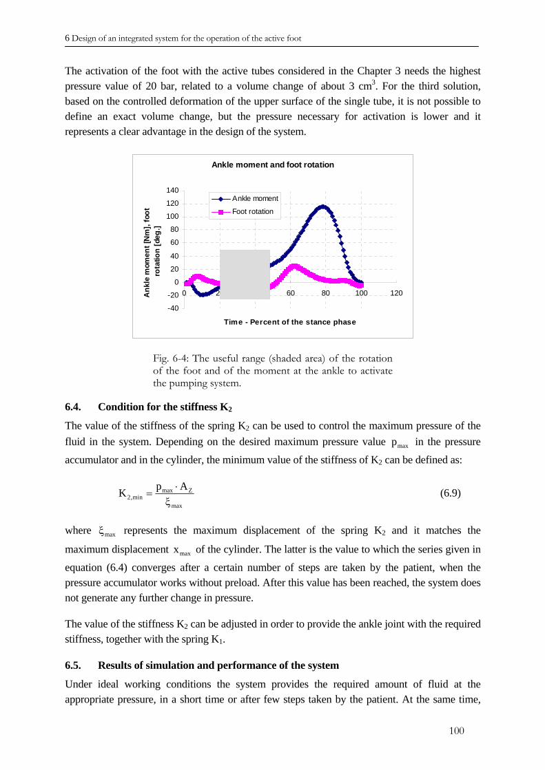
6 Design of an integrated system for the operation of the active foot
The activation of the foot with the active tubes considered in the Chapter 3 needs the highest pressure value of 20 bar, related to a volume change of about 3 cm3. For the third solution, based on the controlled deformation of the upper surface of the single tube, it is not possible to define an exact volume change, but the pressure necessary for activation is lower and it represents a clear advantage in the design of the system.
Ankle moment and foot rotation
-40
-20
0
20
40
60
80
100
120
140
0 20 40 60 80 100 120
Time - Percent of the stance phase
Ank
le m
omen
t [N
m],
foot
ro
tatio
n [d
eg.]
Ankle moment
Foot rotation
Fig. 6-4: The useful range (shaded area) of the rotation of the foot and of the moment at the ankle to activate the pumping system.
6.4. Condition for the stiffness K2
The value of the stiffness of the spring K2 can be used to control the maximum pressure of the fluid in the system. Depending on the desired maximum pressure value in the pressure
accumulator and in the cylinder, the minimum value of the stiffness of Kmaxp
2 can be defined as:
max Z2,min
max
p AK ⋅=
ξ (6.9)
where represents the maximum displacement of the spring Kmaxξ 2 and it matches the
maximum displacement of the cylinder. The latter is the value to which the series given in
equation (6.4) converges after a certain number of steps are taken by the patient, when the pressure accumulator works without preload. After this value has been reached, the system does not generate any further change in pressure.
maxx
The value of the stiffness K2 can be adjusted in order to provide the ankle joint with the required stiffness, together with the spring K1.
6.5. Results of simulation and performance of the system
Under ideal working conditions the system provides the required amount of fluid at the appropriate pressure, in a short time or after few steps taken by the patient. At the same time,
100
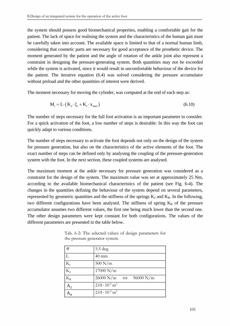
6 Design of an integrated system for the operation of the active foot
the system should possess good biomechanical properties, enabling a comfortable gait for the patient. The lack of space for realising the system and the characteristics of the human gait must be carefully taken into account. The available space is limited to that of a normal human limb, considering that cosmetic parts are necessary for good acceptance of the prosthetic device. The moment generated by the patient and the angle of rotation of the ankle joint also represent a constraint in designing the pressure-generating system. Both quantities may not be exceeded while the system is activated, since it would result in uncomfortable behaviour of the device for the patient. The iterative equation (6.4) was solved considering the pressure accumulator without preload and the other quantities of interest were derived.
The moment necessary for moving the cylinder, was computed at the end of each step as:
(i 2 i 1M L K K x= ⋅ ⋅ξ + ⋅ )max (6.10)
The number of steps necessary for the full foot activation is an important parameter to consider. For a quick activation of the foot, a low number of steps is desirable: In this way the foot can quickly adapt to various conditions.
The number of steps necessary to activate the foot depends not only on the design of the system for pressure generation, but also on the characteristics of the active elements of the foot. The exact number of steps can be defined only by analysing the coupling of the pressure-generation system with the foot. In the next section, these coupled systems are analysed.
The maximum moment at the ankle necessary for pressure generation was considered as a constraint for the design of the system. The maximum value was set at approximately 25 Nm, according to the available biomechanical characteristics of the patient (see Fig. 6-4). The changes in the quantities defining the behaviour of the system depend on several parameters, represented by geometric quantities and the stiffness of the springs K2 and KR. In the following, two different configurations have been analysed. The stiffness of spring KR of the pressure accumulator assumes two different values, the first one being much lower than the second one. The other design parameters were kept constant for both configurations. The values of the different parameters are presented in the table below.
Tab. 6-2: The selected values of design parameters for the pressure generator system.
ϕ 5.5 deg. L 40 mm K1 500 N/m K2 17000 N/m KR 26000 N/m ⇔ 96000 N/m
ZA 2.01 ⋅ 10-4 m2
RA 2.01 ⋅ 10-4 m2
101
6 Design of an integrated system for the operation of the active foot
The quantities of interest that describe the operation of the system in steps required are calculated using the displacement of the piston of the cylinder ξ , the displacement of the pressure accumulator piston xR, the variation of the pressure in the pressure accumulator and the moment at the ankle. The changes in these quantities are represented in the figure below, for both configurations.
The variation in the quantities describing the state of the system as the patient takes an increasing number of steps depends heavely on the stiffness KR. For high values of KR, the quantities converge to the limit in few steps, as presented in Fig. 6-5. However, the disadvantage of a configuration in which the stiffness KR has high stiffness values, is that only a small quantity of fluid can be stired in the pressure accumulator.
a b
c d
Fig. 6-5: The behaviour of the hydraulic system for two different values of the stiffness KR: a) Change in value of the pressure. b) Ankle moment. c) Displacement of the piston of the cylinder. d) Displacement of the pressure accumulator piston - PA.
102
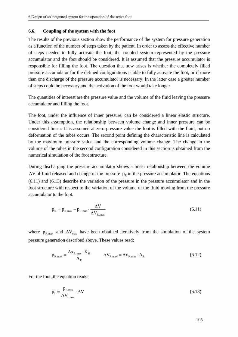
6 Design of an integrated system for the operation of the active foot
6.6. Coupling of the system with the foot
The results of the previous section show the performance of the system for pressure generation as a function of the number of steps taken by the patient. In order to assess the effective number of steps needed to fully activate the foot, the coupled system represented by the pressure accumulator and the foot should be considered. It is assumed that the pressure accumulator is responsible for filling the foot. The question that now arises is whether the completely filled pressure accumulator for the defined configurations is able to fully activate the foot, or if more than one discharge of the pressure accumulator is necessary. In the latter case a greater number of steps could be necessary and the activation of the foot would take longer.
The quantities of interest are the pressure value and the volume of the fluid leaving the pressure accumulator and filling the foot.
The foot, under the influence of inner pressure, can be considered a linear elastic structure. Under this assumption, the relationship between volume change and inner pressure can be considered linear. It is assumed at zero pressure value the foot is filled with the fluid, but no deformation of the tubes occurs. The second point defining the characteristic line is calculated by the maximum pressure value and the corresponding volume change. The change in the volume of the tubes in the second configuration considered in this section is obtained from the numerical simulation of the foot structure.
During discharging the pressure accumulator shows a linear relationship between the volume of fluid released and change of the pressure V∆ Rp in the pressure accumulator. The equations
(6.11) and (6.13) describe the variation of the pressure in the pressure accumulator and in the foot structure with respect to the variation of the volume of the fluid moving from the pressure accumulator to the foot.
R R,max R,maxR,max
Vp p pV∆
= − ⋅∆
(6.11)
where and have been obtained iteratively from the simulation of the system
pressure generation described above. These values read: R,maxp maxV∆
R.max RR,max R.max R.max R
R
x Kp VA
∆ ⋅= ∆ = ∆x A⋅ (6.12)
For the foot, the equation reads:
f ,maxf
f ,max
pp
V= ⋅
∆V∆ (6.13)
103
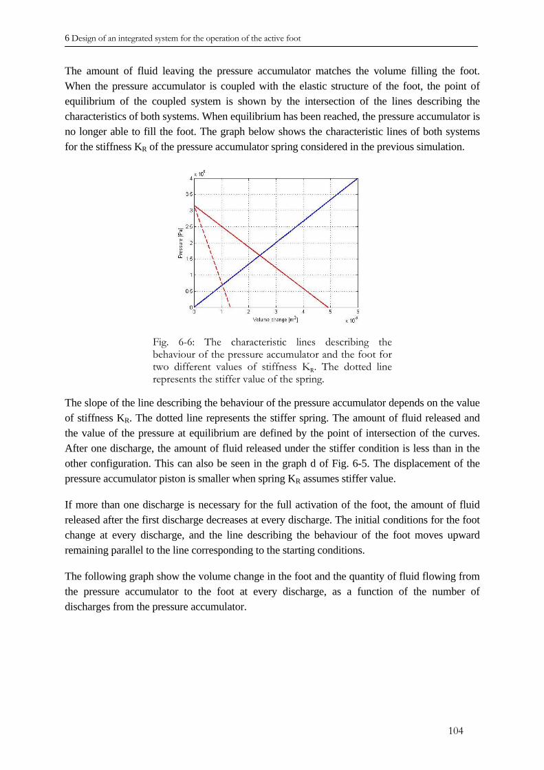
6 Design of an integrated system for the operation of the active foot
The amount of fluid leaving the pressure accumulator matches the volume filling the foot. When the pressure accumulator is coupled with the elastic structure of the foot, the point of equilibrium of the coupled system is shown by the intersection of the lines describing the characteristics of both systems. When equilibrium has been reached, the pressure accumulator is no longer able to fill the foot. The graph below shows the characteristic lines of both systems for the stiffness KR of the pressure accumulator spring considered in the previous simulation.
Fig. 6-6: The characteristic lines describing the behaviour of the pressure accumulator and the foot for two different values of stiffness KR. The dotted line represents the stiffer value of the spring.
The slope of the line describing the behaviour of the pressure accumulator depends on the value of stiffness KR. The dotted line represents the stiffer spring. The amount of fluid released and the value of the pressure at equilibrium are defined by the point of intersection of the curves. After one discharge, the amount of fluid released under the stiffer condition is less than in the other configuration. This can also be seen in the graph d of Fig. 6-5. The displacement of the pressure accumulator piston is smaller when spring KR assumes stiffer value.
If more than one discharge is necessary for the full activation of the foot, the amount of fluid released after the first discharge decreases at every discharge. The initial conditions for the foot change at every discharge, and the line describing the behaviour of the foot moves upward remaining parallel to the line corresponding to the starting conditions.
The following graph show the volume change in the foot and the quantity of fluid flowing from the pressure accumulator to the foot at every discharge, as a function of the number of discharges from the pressure accumulator.
104
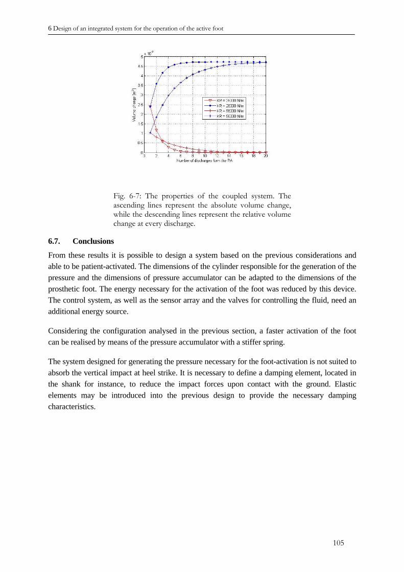
6 Design of an integrated system for the operation of the active foot
Fig. 6-7: The properties of the coupled system. The ascending lines represent the absolute volume change, while the descending lines represent the relative volume change at every discharge.
6.7. Conclusions
From these results it is possible to design a system based on the previous considerations and able to be patient-activated. The dimensions of the cylinder responsible for the generation of the pressure and the dimensions of pressure accumulator can be adapted to the dimensions of the prosthetic foot. The energy necessary for the activation of the foot was reduced by this device. The control system, as well as the sensor array and the valves for controlling the fluid, need an additional energy source.
Considering the configuration analysed in the previous section, a faster activation of the foot can be realised by means of the pressure accumulator with a stiffer spring.
The system designed for generating the pressure necessary for the foot-activation is not suited to absorb the vertical impact at heel strike. It is necessary to define a damping element, located in the shank for instance, to reduce the impact forces upon contact with the ground. Elastic elements may be introduced into the previous design to provide the necessary damping characteristics.
105

6 Design of an integrated system for the operation of the active foot
REFERENCES CHAPTER VI
[6.1] Z. Stinus: “Biomechanik und Beurteilung des mikroprozessorgesteuerten Exoprothesenkniegelenkes C-Leg“, Zeitschrift für Orthopädie und ihre Grenzgebiete, 2000, 138, 278-282.
[6.2] J.E. Pratt, B.T. Krupp, C.J. Morse: „The Roboknee: An Exoskeleton for Enhancing Strength and Endurance During Walking”, Proceedings of the 2004 IEEE International Conference on Robotics and Automation, New Orleans, LA, April 2004.
[6.3] G. Marro: “Controlli Automatici”, Zanichelli, 1997 (in italian).
106
7. Evaluation of the results and conclusions
During the stance phase of the human gait, the prosthetic foot transfers the loads between the ground and the lower limbs and ensures the stability of the stride. The plantar spring is the element of the prosthetic foot that most greatly influences the gait pattern. An energy-efficient gait is an important characteristic for the patient wearing a prosthetic limb.
The purpose of this project is the design of a plantar spring, able to adapt the shape which it assumes under the influence of the ground reaction forces, in order to enhance the gait efficiency and comfort of the patient.
Three different concepts for the active variation of the shape of the plantar spring have been presented.
The first concept is represented by the static adjustment of the bent shape of the plantar spring by means of solid-state actuators. Piezoceramic elements shaped in the form of thin plates can be bonded to the upper and lower surfaces of the plantar spring and activated in order to reduce the deformation of the structure. The curvature induced by the actuators compensates the deformation due to the GRF. This solution is easy to implement in a prototype and the technology for realisation is available and well known. The piezoceramic plates only slightly affect the outer geometry of the plantar spring, and the electrical devices needed for activation may also be miniaturised. Furthermore, no moveable parts are needed to activate the piezoceramic actuators. Inspite of these advantages, this solution presents several drawbacks. The static response variation is very small and far from the desired value. Furthermore, the strain values of the plantar spring outfitted with the piezoceramic layers exceed the admissible values for the piezoceramic material. The strain distribution would lead to a fast degradation of the ceramic properties.
The second concept is based on the possibility of increasing the bending stiffness of a beam-like elliptical tube by deforming the shape of the cross-section of the beam. The hollow, thin walled beam is filled with a hydraulic fluid: The deformation of the cross-section, due to the influence of inner pressure leads to a variation in the moment of inertia of the elliptical cross-section, and therefore, to an increased bending stiffness of the beam represented by the tube. The numerical results of a tube with a lower stiffening plate have shown the feasibility of this concept. It has been possible to reach the desired change in bending stiffness and the experimental tests verified and validated the numeric results. This concept was extended to the plantar spring. Three tubes, as active elements, were integrated into a passive lower plate. The integrated structure replaces the function of the conventional plantar spring. Despite the good results obtained by the analysis of the single tube, the change in bending stiffness of the plantar spring, based on this concept, was considerably lower. The results of the finite element simulation were better than those provided by the active plantar spring based on the piezoceramic actuators, and the experimental tests have only partially confirmed the numerical results. Furthermore, the bonding of the active tubes with the lower plate was damaged during the test performed by the patient. This prototype has shown that is possible to hydraulically activate the foot and that the hydraulic components can be integrated into the new plantar spring.
107
In order to overcome the drawbacks of the previous concept, a third prototype has been designed. This prototype emphasises the bending stiffness of the active element of the plantar spring, and improves the connection between the passive plate and the active part. A flat thin hollow cylinder makes up the active element. Together with the stiffening plate, they provide the necessary bending stiffness to achieve a comfortable gait for the patient. Under the forces of the bending load, the upper surface of the tube is subjected to an inward deformation. Filling the tube with a hydraulic fluid, it is possible to vary the bending stiffness of the plantar spring by controlling the inward deformation of the upper surface. The inner pressure of the hydraulic fluid reduces the deformation of the upper surface of the tube, and as a consequence, the bending stiffness of the plantar spring. The results of the finite element simulation fulfilled the desired change in bending stiffness. Several prototypes were designed according to input from patient. Unfortunately, experimental tests did not confirm the good results of the numerical simulations. The latter concept presents several advantages compared to the others. The numerical results confirmed the possibility of varying the bending stiffness as desired. Manufacture of the foot was realised, considering the difficulties encountered with the previous prototype. The plantar spring, based on this new concept, has passed the experimental tests as well as the walking tests performed by the patient. The connection of the active tube to the lower plate did not prove problematic and the gait comfort has been enhanced. Inspite of these positive results, the patient was not able to confirm a difference in bending stiffness when the plantar spring was activated.
This last prototype offers the potential to be further developed to achieve the desired characteristics. A suitable system for pressure generation was designed. Considering the specific problem, a reduced amount of external energy is needed. Furthermore, the system can be integrated in the region of the ankle joint of the available foot.
Beyond the technical success of this device, it is necessary to carefully take into account its influence on the overall biomechanical behaviour of the foot and the prosthetic leg. The acceptance of the new device by the patient plays a key role in the success of the active foot.
The analysis of the new plantar spring and its effect on the gait pattern can be improved, considering a multi-body simulation of the gait. It is possible to define a combined analysis in which the flexible foot is integrated into the multi-body simulation to assess the real biomechanical behaviour of the prosthetic leg. The resulting ground reaction forces can then be used as input for the finite element simulation, and the characteristics of the foot can be optimised with regards to the loads encountered with a flexible foot. Iteratively, it is possible to optimise the foot structure, taking into account the overall dynamic of the gait.
108
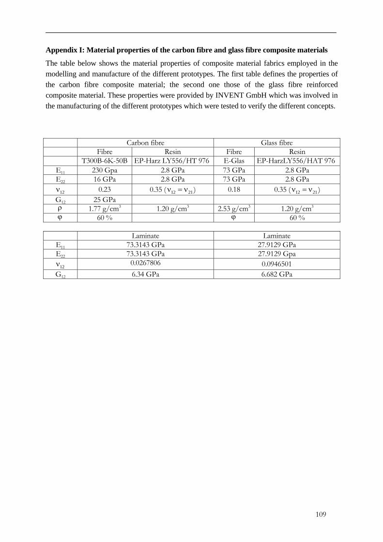
Appendix I: Material properties of the carbon fibre and glass fibre composite materials
The table below shows the material properties of composite material fabrics employed in the modelling and manufacture of the different prototypes. The first table defines the properties of the carbon fibre composite material; the second one those of the glass fibre reinforced composite material. These properties were provided by INVENT GmbH which was involved in the manufacturing of the different prototypes which were tested to verify the different concepts.
Carbon fibre Glass fibre Fibre Resin Fibre Resin
T300B-6K-50B EP-Harz LY556/HT 976 E-Glas EP-HarzLY556/HAT 976E11 230 Gpa 2.8 GPa 73 GPa 2.8 GPa E22 16 GPa 2.8 GPa 73 GPa 2.8 GPa
12ν 0.23 0.35 ( 12 21ν = ν ) 0.18 0.35 ( ) 12 21ν = νG12 25 GPa ρ 1.77 g/cm3 1.20 g/cm3 2.53 g/cm3 1.20 g/cm3
ϕ 60 % ϕ 60 %
Laminate Laminate E11 73.3143 GPa 27.9129 GPa E22 73.3143 GPa 27.9129 Gpa
12ν 0.0267806 0.0946501 G12 6.34 GPa 6.682 GPa
109
VALERIO CARLI
Place and Date of birth: Rome, 22 September 1969
Nationality: Italian Work experiences
2001 – Present Researcher at the Technical University of Darmstadt, Department of “System Reliability and Machine Acoustics”. 1999 – 2001 Researcher at the German Aerospace Center (DLR) of Braunschweig – “Adaptronic” department. Education
2001 – present Doctoral candidate in Mechanical Engineering at the Technical University of Darmstadt, department of “System Reliability and Machine Acoustics.” 1988 – 1999 Bachelor of Science in Aeronautical Engineering, University of Rome “La Sapienza.” Publications
• L. F. Campanile, V. Carli, D. Sachau, S. Seelecke “Extensive geometric adaptability in aerospace
structures by means of Shape Memory Alloys,” Proc. 38th Annual Conference of Metallurgists, Quebec City, Canada, August 1999.
• L. F. Campanile, V. Carli, D. Sachau “Adaptive wing model for wind channel test” presented at the NATO-RTO-AVT Symposium on “Active control technology for enhanced performance operational capabilities of military aircraft, land vehicles and sea vehicles,” Braunschweig (Germany) 8-11 May 2000.
• L. F. Campanile, V.Carli, R. Keimer,“Der Fischmaulaktuator fuer die adaptive Konturbuele. Experimentelle Karakterisierung des Federkorpers,“ IB 131-2000/29.
• V. Carli, U. Elhert “Numerical Investigation of a 2D Demonstrator of an Adaptive Wing - Application of the “belt-rib” concept to a fighter aircraft wing,” IB 131-2001/16.
• V. Carli, L. F. Campanile, D. Sachau “Further investigations and a new application of the “belt-rib” concept: Influence of the “T” solid state joints and numerical results,” presented at the “2001 Joint Applied Mechanics and Materials Summer Conference,” San Diego, California, June 27-29, 2001.
• V.Carli, T. Doll, L. Kurtze, T. Bein: “Implementation of an Active Controlled system: The Active Façade,” Adaptronic Congress, Goettingen, Germany, May 3 – 4, 2006.
110