Embed Size (px)
Citation preview

Propulsion System Health Monitoring
An Insight into Wear Debris Analysis
Adrian Weller, NZ Defence Technology Agency [email protected]
ANZSASI Seminar, 6 June 2015
Auckland, New Zealand

• Provide advice to the RNZAF to:
– Support continued airworthiness
– Prevent flight safety events
– Increase aircraft availability/reduce cost of ownership
• Propulsion systems:
– Gas turbine engines/gearboxes/helicopter drivetrains
DTA Propulsion System Health Monitoring

NZDF Context - Motivation • Small fleets - U/S aircraft - high impact on capability
• Deployed A/C – minimal facilities and spares available
– E.g. Antarctic Flights, helos embarked on ships, austere environments, in-theatre ops etc.
• Need for increased warning lead-time to required maintenance intervention
• Oil-wetted component defects significant driver for unscheduled maintenance
Wear debris analysis identified as one area requiring enhancement

Wear Debris Analysis - Definition • Wear Debris Analysis infers the health of oil-wetted components from debris
liberated from wear modes within the system
• Provides data on:
– Wear modes
• Morphology
– Origin of debris
• elemental composition
– State of defect progression
• Size/quantity
• Debris rate

• WDA employed by OEMs as a prime means of detecting oil-wetted
component defects
– In-line Magnetic chip detectors (MCDs) – indicating/passive
– Filter debris analysis
– In-line real-time particle detection (very limited application)
Wear Debris Analysis – Typical Aircraft Systems
Oil flow
MCD
Oil Line
Debris
Ferromagnetic debris
attracted to MCD

Wear Debris Analysis – Typical Aircraft Systems
Lower MRGB
Chip Detector
Upper MRGB
Chip Detector
Efficacy of MCDs vary between
various designs

• OEMs provide AMM inspection criteria for wear debris
• First Line assessment visual inspection process has changed little over time
• Inspection guidance can be ambiguous/open to interpretation
– Often no detail on inspection method
– Often no detail on filter debris inspection
• First Line assessment visual inspection:
– Quantity and size
– Morphology
• Within limits - no further review – Sample may not be retained
• Out of limits
– Requires engineering review
– Possibly laboratory analysis
Wear Debris – Serviceability Assessment

Wear Debris – Serviceability Assessment
Example of generic AMM serviceability criteria for wear debris
Type Qty/size Prob Cause Action
Steel Fuzz, fine hair-like particles or granular form Normal wear None
Particles in splinter form Usually indicates
failure
Perform
serviceability check
Thin flakes not exceeding 0.031 inch (0.78 mm) in
diameter and 0.25 inch (6.35 mm) in length. Qty
not to exceed 20 flakes
Small qty will not
cause bearing failure
Perform
serviceability check
More than 20 flakes not exceeding 0.031 inch
(0.78 mm) in diameter or any Qty of flakes
exceeding the above dims
Usually indicates
failure
Perform
serviceability check
How do you measure this in the field?

Wear Debris – Serviceability Check Example Generic procedure for a helicopter main rotor gearbox
• Indications – MCD chip light – Assess iaw AMM criteria
– Filter bypass
– Other (high vib etc.)
• Perform serviceability check – Perform 30 min ground run at flight RPM – if OK
– Perform 30 min hover check
– Inspect MCDs
• if QTY of particles increased – Reject gearbox OR
• If QTY is less – assess debris and repeat serviceability check OR
• If QTY is Nil – continue in service

Wear Debris – Engineering Review
• Inputs to serviceability assessment:
– Lab analysis of wear debris sample – composition, morphology
– Maintenance history
– Known and predicted wear modes
– Engineering data – e.g. metal map
– Trend data – wear debris and other e.g. vibs
– Engineering judgement
• Output: – Diagnosis: Go/No-go (based on AMM criteria)
– Prognosis: time until required maintenance intervention
– Mandated inspections/monitoring if remaining in service
• Issues – Data for engineering review may not be available
– SMEs may be remote from samples – delay in analysis
– Variable experience of personnel in WDA

Case Study –Iroquois T53 gearbox
• Multiple MCD indications over period of 100+ hours – all assessed as ‘S’
• Final in-service MCD indication – serviceability check
– Further MCD indication 3 min into 20 min hover check
– Teardown found 2 fractured gear teeth, abnormal wear on gear surfaces
– Wear debris precursors not detected

Case Study – T56 Accessory Gearbox (AGB)
• Aircraft deployed on operation
• Mag plugs checked – Accessory Gearbox Mag plug had debris
• Debris assessed as ‘fuzz’ and within limits – sample sent to DTA slow time for review
• Results:
– ‘Fuzz’ shown to be fatigue spall flakes of bearing material
– Particles <1/16th inch limit
• Engine changed
AGB Lower mag plug: Visual
1/16 inch (1.6 mm) limit
AGB Lower mag plug:
Macro lens photo Lower mag plug: SEM image
• Eurocopter AS332L2 Super Puma G-REDL main gearbox failure 2009 [1], [2]
• Ruptured planet gear caused catastrophic failure of gearbox
• Main rotor separated – fatal accident 16 killed
• Wear debris precursors were present – incorrectly diagnosed
• Noted from report on the AMM WDA process: “No illustrations or photographs of representative
particles, to aid the process of identification, are included in the procedure”
Case Study: Super Puma G-REDL 2009
Eurocopter AS332L2 Super Puma main gearbox epicyclic gear set
Failed Eurocopter AS332L2 Super Puma G-REDL
main gearbox [1] UK AAIB Special Bulletin: 5/2009 – Eurocopter AS332L2 Super Puma, G-REDL, North Sea, 2009.
[2] UK AAIB Aircraft Accident Report 2/2011: Report on the accident to Aerospatiale (Eurocopter) AS332 L2
Super Puma, registration G-REDL 11 nm NE of Peterhead, Scotland on 1 April 2009.

• Primarily based on MCD findings
• Inspection criteria can be ambiguous
• In general, basic WDA systems and serviceability focus on confirmation of
failures in late stages
• Refinement of process is operator dependent
Summary Serviceability Assessment
Operating Hours
We
ar D
eb
ris R
ate
wear debris rate
Failure if allowed to remain in
service

DTA Development – Filter Debris Analysis • Filters contain valuable wear debris data
• Potential to provide significant lead time to failure over MCDs alone [3]
• Advantage – applicable to all fleets without modification
• FDA under utilised
• Time consuming
• Limited guidance
• Lack of capability to extract and analyse debris
• Visual inspection of filter pleats inadequate to reliably detect bearing spall particles (200 µm)
[3] Toms, A., GasTOPS Inc., Jordan. E., and Humphrey, G., “The Success of Filter Debris Analysis for J52
Engine Condition Based Maintenance”, AIAA-2005-4338, 41st AIAA/ASME/SAE/ASEE Joint Propulsion
Conference and Exhibit, Tucson, Arizona, July 10-13, 2005.

FilterCHECK FC400 • RNZAF procured GasTOPS FC400 in 2009 on DTA advice
– Automatic debris extraction
– Quantifies debris (Inductive sensor)
– Produces debris patch for further analysis (if needed)
– XRF system can provide aggregate composition (NOT used)
• DTA developed analysis processes/limits [4]
• RNZAF routinely sample filters for trending – Reduced inspection interval trending if defects detected
[4] Weller, A.J. Defence Technology Agency, New Zealand Defence Force, “Enhancing Propulsion System
Condition Monitoring for the RNZAF”, AIAC14 Fourteenth Australian International Aerospace Congress,
Melbourne, Victoria, Australia, 2011.

FilterCHECK FC400 -Debris extraction
• Consistent extraction method - Only variables are:
– Time on filter
– Amount of debris
• MetalSCAN sensor output:
– Particle count
– Particle size / Type (Ferrous or Non Ferrous)
• Debris rate derived from hours on filter
– Primary trend metric
Flow
Metalscan Sensor
Filter

FilterCHECK FC400 –Debris Patch
• All debris collected above 60 µm in size on filter patches
• Debris Patches reviewed by RNZAF
– Morphology inspection via optical microscope
• DTA developed visual inspection guidance used

NO MORPHOLOGY
QUANTITY/SIZE
RNZAF/DTA Wear Debris Analysis Process
YES
DTA Analysis
No action required
NO
Engineering Review
– Further analysis required?
Send to
DTA
DTA Report
Laboratory Analysis
Engineering Review
FilterCHECK Optical microscope
QUANTITY
SIZE
MORPHOLOGY
Visual Inspection MCD
Samples
Filter
samples
First Line Assessment
- Within AMM limits?
YES
No action required
Final Assessment
– Serviceability disposition
- Further monitoring requirements

NO
YES
DTA Wear Debris Analysis Process
SEM
Detailed assessment
of Morphology
EDS
Composition of each
particle assessed
Determine match to
component Metal Maps
Optical Microscope
Detailed assessment of
Morphology (50 X)
Remarkable debris present?
Extract representative subsample
for SEM/EDS analysis
DTA Report
Detailed debris
Summary
DTA Report
- Nil remarkable
debris
Sample
received
- Filter patch
- MCD sample
- Sample details
DTA Corp
Knowledge
Physics of failure
System specific data
Failure case studies
Mechanical and materials
engineering

• Scanning Electron Microscope (SEM) - morphology analysis
• Energy dispersive x-ray spectroscopy (EDS) - elemental composition
DTA Wear Debris Analysis Process

Case Study – T56 Reduction Gearbox (RGB)
Pinion Bearing
• Cruise FL280
• No. 1 engine Torque and RPM fluctuations
• Excessive red fluid streaming from engine
• Engine shutdown – return to origin
• Un-eventful landing after 4 hours on 3 engines

Case Study – T56 RGB pinion bearing
Magnetic Chip Detector Debris (Post Failure)
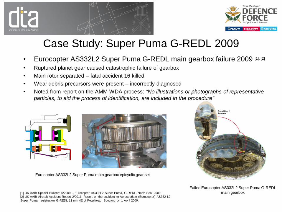
Case Study – T56 RGB pinion bearing
• SEM/EDS Analysis sample at failure:
– M50 NiL bearing steel (AMS6278) – Match to pinion bearing
– 9310 (AMS 6265) gear steel fragments
Magnetic Chip Detector Debris (Post Failure)

Case Study – T56 RGB pinion bearing
Rear Pinion Bearing Inner Race Pinion Rear Bearing
Bearing Cage Heat Damage Pinion Rear Bearing Rolling Element

Case Study – T56 RGB pinion bearing
Inner Diaphragm Damage Torque-meter Housing
Torque-meter Pickup Gouging Main Accessory Gear Damage

Case Study – T56 RGB pinion bearing
• SEM/EDS analysis 250 hours prior to failure
– Mag plugs assessed as within limits

Case Study – T56 RGB pinion bearing
• Morphology inspection
0
10
20
30
40
50
60
70
050100150200250
De
bri
s Q
ua
nti
ty (
Co
un
ts/H
r)
Flight Time Prior to Failure (Hrs)
Filtercheck ferrous debris rate
Small Particles
Med Particles
Large Particles
Total Particles
A - Monitoring since traces of M50 NiL first detected
B - Accelerated failure rate un-detected due to overseas deployment (3 filter samples)
A B
Fleet alert limit
σ + 3 S.D

FDA Case Studies – Examples of catches
• RB211-535 – Detected power take off shaft steady bearing failure
– Allowed repair on-wing
• RB211-535 – Pre first B757 Antarctic flight - detection of major bearing defect
– Avoided flight safety risk/unscheduled engine change
• T56 – multiple reduction gearbox defects detected allowing scheduled
intervention
• T56 – numerous cases detecting starter magnetic seal failures
– Allowed on-wing repair
– Avoided unnecessary engine removal

DTA Work: Advancing WDA
• Desire to standardise WDA to:
– Allow more robust assessment of component health
– Give guidance to operators
– Provide standard means of analysis for laboratories
– Provide a basis for OEMs to standardise AMM methods and inspection criteria
• DTA through TTCP nations produced FDA guidance document
– None existed prior
• Covers:
– Robust methods for debris extraction from filters
– Analysis methods and requirements for detection of component defects
– Interpretation guidance

DTA Work: Advancing WDA
• TTCP FDA document adapted and published by ASTM (2014)
– Designation: D7898 − 14
– “Standard Practice for Lubrication and Hydraulic Filter Debris Analysis (FDA) for Condition
Monitoring of Machinery”
– Covers debris extraction, analysis and reporting
– Intended for aircraft systems (also applicable to wider machinery)
– Includes simple manual methods and automated methods
• Future work planned to develop more comprehensive standard practice for all
wear debris analysis

DTA Work: Advancing WDA
• Reviewing new analysis technology to enable deployed WDA
– Strong need to have accurate serviceability assessment without delays
• Portable elemental analysis
– X-ray fluorescence
– Laser-induced breakdown spectroscopy (LIBS) based
• Portable microscope image capture systems
– Compact microscopes
– Digital imaging techniques

Summary
• Legacy MCD based AMM inspection methods/criteria:
– Robustness of assessment heavily dependant on operator competency
– WDA assessment process is variable between OEMs
– Generally aimed at confirming late stages of a failure (Often insufficient warning to prevent unscheduled maintenance)
– Inspection criteria is typically vague and can lead to incorrect assessment
– Delay in accurate analysis can incur flight safety risk
• RNZAF WDA programme
– Underpinned by DTA SEM/EDS capability and corporate knowledge
– Augmented by filter debris analysis - has proven to detect significant proportion of defects with increased lead time
– Future work to focus on enhancing deployed WDA capability
• DTA WDA Advancement Recommendations
– Industry wide standards needed to improve and standardise WDA best practice amongst OEMs and operators
– FDA ASTM standard D7898 − 14 is now in place
– Civil aviation is encouraged to participate in future WDA standards development work!
• Failure investigations
– Consider MCDs and filters and residual internal debris Fe and Nfe – very few failure modes produce no wear debris
– Ask the question was robust WDA conducted?