Embed Size (px)
Citation preview
ADRIAN HILL DEVELOPMENTS
NUMBER 86
CABANA BOULEVARD
BENOWA
JOB NUMBER - 5248
NOTES:
* IMAGES ARE DIAGRAMATIC ONLY
* REFER TO ELEVATIONS FOR DETAILS
PROPOSED DWELLING FOR
Phone (07) 55 203 022Fax (07) 55 203 033
PO Box 2845 Burleigh Heads DC Qld 4220Address: 2/71 Township Drive, West Burleigh, QLD 4219
ABN 73 097 995 616BSA License No: 1129687Email: [email protected]
© Copyright reserved in part or whole. Writtendimensions take preference.
Contractor to verify dimensions.Notify designers of discrepancies.
Failure to do so shall voidthe designers responsibilities.
TH
IS D
ES
IGN
IS
TH
E E
XC
LU
SIV
E P
RO
PE
RT
Y O
F S
TU
AR
T O
SM
AN
BU
ILD
ING
DE
SIG
NS
N.B
AL
L W
RIT
TE
N D
IME
NS
ION
S T
AK
E P
RE
CE
DE
NC
E O
VE
R S
CA
LE
D S
IZE
S
BE
WA
RN
ED
: S
UB
ST
ITU
TIO
N O
F A
NY
ST
RU
CT
UR
AL
ME
MB
ER
S,
AN
D O
R A
NY
VA
RIA
TIO
N T
O A
NY
PA
RT
OF
TH
E D
ES
IGN
WIL
L V
OID
AN
Y
RE
SP
ON
SIB
ILIT
IES
OF
ST
UA
RT
OS
MA
N B
UIL
DIN
G D
ES
IGN
S F
OR
TH
E S
TR
UC
TU
RA
L IN
TE
GR
ITY
AN
D P
ER
FO
RM
AN
CE
OF
TH
E B
UIL
DIN
G
CLIENT
PROJECT
JOB NUMBER
BUILDER
DRAWN BY CHECKED BY
DESIGN
DATE
SCALES AMENDMENTS
SHEET NUMBERof
CHARTERED
MEMBER OF
ADRIAN HILL
DEVELOPMENTS
PROPOSED DWELLING
NUMBER 86
CABANA BOULEVARDBENOWA
5248
RH
A 15/10/2013
B061113C121113D131113E201113F271113
SO
CUSTOM
1:100 @ A2
2 19
queensland inc.association of
building designers
DESCRIPTIONREV. DATE
PRELIMINARY PLANS ISSUEDA 151013
DENOTES LOCATION OF SMOKE DETECTORS (refer electrical layout plans), TOBE HARD WIRED WITH EMERGENCY BACK-UP AND COMPLY WITH AS 3786.
WIND SPEED AS NOMINATED ON BRACING PLAN.
PROVIDE LIFT OFF HINGES TO W.C OR OPEN OUT DOOR OR MIN 1200mm CLEARANCEFROM DOOR TO PAN.
EXHAUST FANS FROM SANITARY COMPARTMENTS TO BE DUCTED TO THE OUTSIDEARE AIR OR TO A VENTED ROOF SPACE AND AS PER AS 1668.2
THESE NOTES ARE NEITHER EXHAUSTIVE NOR A SUBSTITUTE FOR REGUALTIONS,STATUTORY REQUIREMENTS, BUILDING PRACTICE OR CONTRACUAL OBLIGATIONS.
ALL CONSTRUCTION MATERIALS SUPPLIED MUST TAKE INTO ACCOUNT PROXIMITY TOCOASTAL OR INDUSTRIAL ENVIRONMENTS, IN ACCORDANCE WITH MANUFACTURERSSPECIFICATIONS
THESE PLANS ARE PROTECTED BY COPY RIGHT AND ARE THE PROPERTY OF THEAUTHOR.
ADRIAN HILL DEVELOPMENTSNUMBER 86
CABANA BOULEVARD
BENOWA
JOB NUMBER - 5248
GENERAL NOTES
DO NOT SCALE PLANS, USE WRITTEN DIMENSIONS ONLY.
THE OWNER/BUILDER SUBCONTRACTOR SHALL VERIFY ALL DIMENSIONS, LEVELS,SETBACKS AND SPECIFICATIONS PRIOR TO COMMENCING WORKS OR ORDERINGMATERIALS AND SHALL BE RESPONSIBLE FOR ENSURING THAT ALL BUILDING WORKSCONFORM TO THE BUILDING CODE OF AUSTRALIA 2006, CURRENT AUSTRALIANSTANDARDS, BUILDING REGULATIONS AND TOWN PLANNING REQUIREMENTS,REPORT ANY DISCREPANCIES TO THIS OFFICE.
ALL WORKS SHALL COMPLY WITH BUT NOT LIMITED TO THE BUILDING CODE OFAUSTRALIAN AND THE AUSTRALIAN STANDARDS LISTED IN NOTE 4.
AS 1288 - 2006 GLASS IN BUILDINGS - SELECTION AND INSTALLATIONAS 1562 - 1992 DESIGN AND INSTALLATION OF SHEET ROOF AND WALL CLADDINGAS 1684 - 2010 NATIONAL TIMBER FRAMING CODEAS 2049 - 2002 ROOF TILESAS 2050 - 2002 INSTALLATION OF ROOF TILESAS 2870 - 1996 RESIDENTIAL SLAB AND FOOTINGS - CONSTRUCTIONAS/NZS 2904 - 1995 DAMP-PROOF COURSES AND FLASHINGSAS 3600 - 2000 CONCRETE STRUCTURESAS 3660 - 2000 BARRIERS FOR SUBTERRANEAN TERMITESAS 3700 - 2001 MASONRY IN BUILDINGSAS 3740 - 2004 WATERPROOFING OF WET AREAS IN RESIDENTIAL BUILDINGSAS 3786 - 1993 SMOKE ALARMSAS 4055 - 2006 WIND LOADINGS FOR HOUSINGAS 4100 - 1998 STEEL STRUCTURES
THESE PLANS SHALL BE READ IN CONJUNCTION WITH ANY STRUCTURAL AND CIVILENGINEERING COMPUTIONS AND DRAWINGS.
SOIL CLASSIFICATION - REFER TO STRUCTURAL ENGINEERS SOIL TEST.
ALL BUILDINGS SHALL BE PROTECTED AGAINST TERMITE ATTACK IN ACCORDANCEWITH AS 3660.1 AND A DURABLE NOTICE SHALL BE PLACED IN THE METER BOXINDICATING TYPE OF BARRIER AND REQUIRED PERIODICAL INSPECTIONS.
SAFETY GLAZING TO BE USED IN THE FOLLOWINGS CASES -i) ALL ROOMS - WITHIN 500mm VERTICAL OF THE FLOORii) BATHROOMS - WITHIN 1500mm VERTICAL OF THE BATH BASEiii) FULLY GLAZED DOORSiv) SHOWER SCREENSv) WITHIN 300mm OF A DOOR AND <1200mm ABOVE FLOOR LEVELvi) WINDOW SIZES ARE NOMINAL ONLY, ACTUAL SIZES WILL VARYWITH MANUFACTURER, FLASHING ALL ROUND.
ALL GUTTERS TO BE STRAMIT QUEENSLANDER QUAD GUTTERING WITH MIN. 100x75RECTANGULAR OR 100 dia. DOWNPIPES, EACH DOWNPIPE SHALL SERVICE A MAXIMUMROOF AREA OF 36 sq.m OR SHALL BE POSITIONED AS PER AS 3500.3, 2003, SECTION 3.
STORMWATER TO BE TAKEN TO THE LEGAL POINT OF DISCHARGE AS DETERMINED BYTHE RELEVANT AUTHORITY.
TILED DECKS OVER LIVABLE AREAS ARE TO BE, IN THE FOLLOWING ORDER OVERTHEFLOOR JOISTS : 19mm COMPRESSED FIBRE CEMENT SHEET, WITH ONE LAYER OFPARCHEM EMERPROOF 750 WITH A SECOND LAYER OF SAND SEED WITH A DFT OF1300 MICRON, INSTALLED TO MANUF. SPECIFICATIONS, AND FLOOR TILES OVER, ALLCORNERS TO HAVE 20mm MASTIC SEALANT UNDER THE PARCHEM EMERPROOF 750.
FOOTINGS NOT TO ENCROACH TITLE BOUNDARIES OR EASEMENTS. IT ISRECOMMENDED THAT WHERE BUILDINGS ARE TO BE LOCATED IN CLOSE PROXIMITYOF BUNDARIES, A CHECK SURVEY BE CONDUCTED BY A LICENSED SURVEYOR.
ALL STEELWORK IN MASONRY TO BE HOT DIP GALVANISED.
ALL WET AREAS TO COMPLY WITH BCA 3.8.1.2 AND AS 3740. SPLASH BACKS SHALL BEIMPERVIOUS FOR 150mm ABOVE SINKS, TROUGHS AND HAND BASINS WITHIN 75mm OFTHE WALL.
PROVIDE WALL TIES AT 600mm SPACINGS BOTH VERTICAL AND HORIZONTAL ANDWITHIN 300mm OF ARTICULATION JOINTS. BRICK TIES TO BE STAINLESS STEEL.
SUB-FLOOR VENTILATION MINIMUM 7500mm sq FOR EXTERNAL WALLS AND 1500mm sqFOR INTERNAL WALLS BELOW BEARER.
THERMAL INSULATION; R2.5 BATTS TO CEILING AND R1.5 BATTS AND REFLECTIVE FOILTO EXTERNAL WALLS OR AS PER ENERGY RATING.
STAIR REQUIREMENTS : MIN. TREAD 240mm, MIN. RISER 115mm, MAX. RISER 190mm,SPACE BETWEEN OPEN TREADS MAX. 125mm. TREADS TO BE NON SLIP SURFACE.BALUSTRADES : MIN. 1000mm ABOVE LANDINGS WITH MAX. OPENING OF 125mm AND INACCORDANCE WITH BCA 3.9.2FOR STAINLESS STEEL BALUSTRADE, REFER TO Table 3.9.2.1 (WIRE BALUSTRADECONSTRUCTION - REQUIRED WIRE TENSION AMD MAXIMUM PERMISSIBLEDEFLECTION) OF THE BCA..
THE BUILDER SHALL TAKE ALL STEPS NECESSARY TO ENSURE THE STABILITY OFEXISTING AND NEW STRUCTURES THROUGH-OUT CONSTRUCTION.
LEGEND
CJ CONSTRUCTION JOINT
DP DOWNPIPE
FP FIRE PLACE
FW FLOOR WASTE
HWS HOT WATER SYSTEM
AC AIR CONDITIONING
PS PLUMBING STACK / DUCT
SP STEEL POST
T.B.C TO BE CONFIRMED
RL RELATIVE LEVEL
AHD AUSTRALIAN HEIGHT DATUM
CSD CAVITY SLIDING DOOR
OHC OVER HEAD CUPBOARD
FG FIXED GLASS
FSR FLOOR SPACE RATIO
LB LOAD BEARING
NGL NATURAL GROUND LINE
UBO UNDER BENCH OVEN
WO WALL OVEN
DW DISHWASHER
MW MICROWAVE
WM WASHING MACHINE
WIR WALK-IN-ROBE
SD SLIDING GLASS DOOR
ASW ALUMINIUM SLIDING WINDOW
ADH ALUM. DOUBLE HUNG WINDOW
AAW ALUM. AWNING WINDOW
ALW ALUM. LOUVRE WINDOW
BCA BUILDING CODE OF AUSTRALIA
AS AUSTRALIAN STANDARDS
SITE NOTES
ALL STORMWATER AND DRAINAGE TO BE IN COMPLIANCE WITH BCAPARTS 3.1.2 & 3.5.2 AS WELL AS AS/NZS 3500.
ENSURE 90mm DIAMETER AGRICULTURAL DRAINS ARE PROVIDED TOTHE BASE OF ALL CUTS AND RETAINING WALLS AND ARE CONNECTEDTO THE STORMWATER SYSTEM VIA SILT PIT/S TO THE RBSREQUIREMENTS.
THE EXTERNAL FINISHED SURFACE SURROUNDING THE BUILDINGMUST BE DRAINED TO MOVE SURFACE WATER AWAY FROM THEBUILDING AND GRADE TO PROVIDE A SLOPE NOT LESS THAN 50mmOVER THE FIRST 1000mm FROM THE BUILDING.
A MINIMUM HEIGHT OF 150mm SHALL BE MAINTAINED BETWEEN THETOP OF THE OVERFLOW GULLY RISER & THE LOWEST FIXTURECONNECTED TO THE DRAIN. THE OVERFLOW GULLY RISER SHALL BELOCATED AT 75mm ABOVE SURROUNDING GROUND LEVEL OR SHALLBE FINISHED AT A HEIGHT TO PREVENT THE INGRESS OF WATERWHEN LOCATED IN A PATH OR PAVED AREA.
CONNECT DOWNPIPES TO LEGAL POINT OF DISCHARGE VIA 100mmDIAMETER UPVC STORMWATER PIPE LAID WITH A MINIMUM FALL OF1:100, DISCHARGE TO THE SATISFACTION OF THE RELEVANTAUTHORITY.
ALL STORMWATER DRAINAGE BELOW GROUND SHALL BE SEWERGRADE WITH NO JOINTS UNDER SLAB INSTALLED TO AS3500.3, 2003.MINIMUM PIPE SIZE 100mmMINIMUM GRADE 1:100
ALL POOL FENCING SHALL BE MIN. 1200mm HIGH AND INACCORDANCEWITH AS 1926.1
PROPOSED DWELLING FOR
RH
LAYOUT AMENDMENTSB 061113RH
LAYOUT AMENDMENTSC 121113RH
MINOR AMENDMENTSD 131113RH
PRELIMINARY ELEVATIONS & ELECTRICAL PLANSE 201113RH
MINOR AMENDMENT + WORKING DRAWINGS ISSUEDF 281113RH
Phone (07) 55 203 022Fax (07) 55 203 033
PO Box 2845 Burleigh Heads DC Qld 4220Address: 2/71 Township Drive, West Burleigh, QLD 4219
ABN 73 097 995 616BSA License No: 1129687Email: [email protected]
© Copyright reserved in part or whole. Writtendimensions take preference.
Contractor to verify dimensions.Notify designers of discrepancies.
Failure to do so shall voidthe designers responsibilities.
TH
IS D
ES
IGN
IS
TH
E E
XC
LU
SIV
E P
RO
PE
RT
Y O
F S
TU
AR
T O
SM
AN
BU
ILD
ING
DE
SIG
NS
N.B
AL
L W
RIT
TE
N D
IME
NS
ION
S T
AK
E P
RE
CE
DE
NC
E O
VE
R S
CA
LE
D S
IZE
S
BE
WA
RN
ED
: S
UB
ST
ITU
TIO
N O
F A
NY
ST
RU
CT
UR
AL
ME
MB
ER
S,
AN
D O
R A
NY
VA
RIA
TIO
N T
O A
NY
PA
RT
OF
TH
E D
ES
IGN
WIL
L V
OID
AN
Y
RE
SP
ON
SIB
ILIT
IES
OF
ST
UA
RT
OS
MA
N B
UIL
DIN
G D
ES
IGN
S F
OR
TH
E S
TR
UC
TU
RA
L IN
TE
GR
ITY
AN
D P
ER
FO
RM
AN
CE
OF
TH
E B
UIL
DIN
G
CLIENT
PROJECT
JOB NUMBER
BUILDER
DRAWN BY CHECKED BY
DESIGN
DATE
SCALES AMENDMENTS
SHEET NUMBERof
CHARTERED
MEMBER OF
ADRIAN HILL
DEVELOPMENTS
PROPOSED DWELLING
NUMBER 86
CABANA BOULEVARDBENOWA
5248
RH
A 15/10/2013
B061113C121113D131113E201113F271113
SO
CUSTOM
1:100 @ A2
3 19
queensland inc.association of
building designers
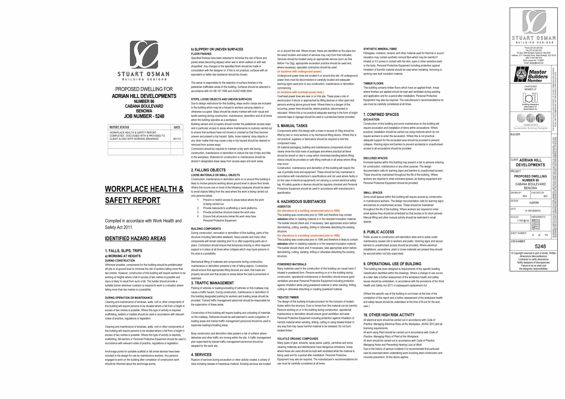
REPORT STATUS DATE
WORKPLACE HEALTH & SAFETY REPORTCOMPLETED - DISCUSSED WITH & PROVIDED TOCLIENT ALONG WITH WORKING DRAWINGS 281113
ADRIAN HILL DEVELOPMENTSNUMBER 86
CABANA BOULEVARD
BENOWA
JOB NUMBER - 5248
b) SLIPPERY OR UNEVEN SURFACES
FLOOR FINISHES
Specified finishes have been selected to minimise the risk of floors and
paved areas becoming slippery when wet or when walked on with wet
shoes/feet. Any changes to the specified finish should be made in
consultation with the designer or, if this is not practical, surfaces with an
equivalent or better slip resistance should be chosen.
The owner is responsible for the selection of surface finishes in the
pedestrian trafficable areas of this building. Surfaces should be selected in
accordance with AS HB 197:1999 and AS/NZ 4586:2004.
STEPS, LOOSE OBJECTS AND UNEVEN SURFACES
Due to design restrictions for this building, steps and/or ramps are included
in the building which may be a hazard to workers carrying objects or
otherwise occupied. Steps should be clearly marked with both visual and
tactile warning during construction, maintenance, demolition and at all times
when the building operates as a workplace.
Building owners and occupiers should monitor the pedestrian access ways
and in particular access to areas where maintenance is routinely carried out
to ensure that surfaces have not moved or cracked so that they become
uneven and present a trip hazard. Spills, loose material, stray objects or
any other matter that may cause a slip or trip hazard should be cleaned or
removed from access ways.
Contractors should be required to maintain a tidy work site during
construction, maintenance or demolition to reduce the risk of trips and falls
in the workplace. Materials for construction or maintenance should be
stored in designated areas away from access ways and work areas.
2. FALLING OBJECTS
LOOSE MATERIALS OR SMALL OBJECTS
Construction, maintenance or demolition work on or around this building is
likely to involve persons working above ground level or above floor levels.
Where this occurs one or more of the following measures should be taken
to avoid objects falling from the area where the work is being carried out
onto persons below.
1. Prevent or restrict access to areas below where the work
is being carried out.
2. Provide toeboards to scaffolding or work platforms.
3. Provide protective structure below the work area.
4. Ensure that all persons below the work area have
Personal Protective Equipment.
BUILDING COMPONENTS
During construction, renovation or demolition of this building, parts of the
structure including fabricated steelwork, heavy panels and many other
components will remain standing prior to or after supporting parts are in
place. Contractors should ensure that temporary bracing or other required
support is in place at all times when collapse which may injure persons in
the area is a possibility.
Mechanical lifting of materials and components during construction,
maintenance or demolition presents a risk of falling objects. Contractors
should ensure that appropriate lifting devices are used, that loads are
properly secured and that access to areas below the load is prevented or
restricted.
3. TRAFFIC MANAGEMENT
Parking of vehicles or loading/unloading of vehicles on this roadway may
cause a traffic hazard. During construction, maintenance or demolition of
this building designated parking for workers and loading areas should be
provided. Trained traffic management personnel should be responsible for
the supervision of these areas.
Construction of this building will require loading and unloading of materials
on the roadway. Deliveries should be well planned to avoid congestion of
loading areas and trained traffic management personnel should be used to
supervise loading/unloading areas.
Busy construction and demolition sites present a risk of collision where
deliveries and other traffic are moving within the site. A traffic management
plan supervised by trained traffic management personnel should be
adopted for the work site.
4. SERVICES
Rupture of services during excavation or other activity creates a variety of
risks including release of hazardous material. Existing services are located
on or around this site. Where known, these are identified on the plans but
the exact location and extent of services may vary from that indicated.
Services should be located using an appropriate service (such as Dial
Before You Dig), appropriate excavation practice should be used and,
where necessary, specialist contractors should be used.
(in locations with underground power)
Underground power lines are located in or around this site. All underground
power lines must be disconnected or carefully located and adequate
warning signs used prior to any construction, maintenance or demolition
commencing.
(in locations with overhead power lines )
Overhead power lines are near or on this site. These pose a risk of
electrocution if struck or approached by lifting devices or other plant and
persons working above ground level. Where there is a danger of this
occurring, power lines should be, where practical, disconnected or
relocated. Where this is not practical adequate warning in the form of bright
coloured tape or signage should be used or a protective barrier provided.
5. MANUAL TASKS
Components within this design with a mass in excess of 25kg should be
lifted by two or more workers or by mechanical lifting device. Where this is
not practical, suppliers or fabricators should be required to limit the
component mass.
All material packaging, building and maintenance components should
clearly show the total mass of packages and where practical all items
should be stored on site in a way which minimises bending before lifting.
Advice should be provided on safe lifting methods in all areas where lifting
may occur.
Construction, maintenance and demolition of this building will require the
use of portable tools and equipment. These should be fully maintained in
accordance with manufacturer’s specifications and not used where faulty or
(in the case of electrical equipment) not carrying a current electrical safety
tag. All safety guards or devices should be regularly checked and Personal
Protective Equipment should be used in accordance with manufacturer’s
specification.
6. HAZARDOUS SUBSTANCES
ASBESTOS
(for alterations to a building constructed prior to 1990)
This building was constructed prior to 1990 and therefore may contain
asbestos either in cladding material or in fire retardant insulation material.
The builder should check and, if necessary, take appropriate action before
demolishing, cutting, sanding, drilling or otherwise disturbing the existing
structure.
(for alterations to a building constructed prior to 1986)
This building was constructed prior to 1986 and therefore is likely to contain
asbestos either in cladding material or in fire retardant insulation material.
The builder should check and, if necessary, take appropriate action before
demolishing, cutting, sanding, drilling or otherwise disturbing the existing
structure.
POWDERED MATERIALS
Many materials used in the construction of this building can cause harm if
inhaled in powdered form. Persons working on or in the building during
construction, operational maintenance or demolition should ensure good
ventilation and wear Personal Protective Equipment including protection
against inhalation while using powdered material or when sanding, drilling,
cutting or otherwise disturbing or creating powdered material.
TREATED TIMBER
The design of this building includes provision for the inclusion of treated
timber within the structure. Dust or fumes from this material can be harmful.
Persons working on or in the building during construction, operational
maintenance or demolition should ensure good ventilation and wear
Personal Protective Equipment including protection against inhalation of
harmful material when sanding, drilling, cutting or using treated timber in
any way that may cause harmful material to be released. Do not burn
treated timber.
VOLATILE ORGANIC COMPOUNDS
Many types of glue, solvents, spray packs, paints, varnishes and some
cleaning materials and disinfectants have dangerous emissions. Areas
where these are used should be kept well ventilated while the material is
being used and for a period after installation. Personal Protective
Equipment may also be required. The manufacturer’s recommendations for
use must be carefully considered at all times.
SYNTHETIC MINERAL FIBRE
Fibreglass, rockwool, ceramic and other material used for thermal or sound
insulation may contain synthetic mineral fibre which may be harmful if
inhaled or if it comes in contact with the skin, eyes or other sensitive parts
or the body. Personal Protective Equipment including protection against
inhalation of harmful material should be used when installing, removing or
working near bulk insulation material.
TIMBER FLOORS
This building contains timber floors which have an applied finish. Areas
where finishes are applied should be kept well ventilated during sanding
and application and for a period after installation. Personal Protective
Equipment may also be required. The manufacturer’s recommendations for
use must be carefully considered at all times.
7. CONFINED SPACES
EXCAVATION
Construction of this building and some maintenance on the building will
require excavation and installation of items within excavations. Where
practical, installation should be carried out using methods which do not
require workers to enter the excavation. Where this is not practical,
adequate support for the excavated area should be provided to prevent
collapse. Warning signs and barriers to prevent accidental or unauthorised
access to all excavations should be provided.
ENCLOSED SPACES
Enclosed spaces within this building may present a risk to persons entering
for construction, maintenance or any other purpose. The design
documentation calls for warning signs and barriers to unauthorised access.
These should be maintained throughout the life of the building. Where
workers are required to enter enclosed spaces, air testing equipment and
Personal Protective Equipment should be provided.
SMALL SPACES
Some small spaces within this building will require access by construction
or maintenance workers. The design documentation calls for warning signs
and barriers to unauthorised access. These should be maintained
throughout the life of the building. Where workers are required to enter
small spaces they should be scheduled so that access is for short periods.
Manual lifting and other manual activity should be restricted in small
spaces.
8. PUBLIC ACCESS
Public access to construction and demolition sites and to areas under
maintenance causes risk to workers and public. Warning signs and secure
barriers to unauthorised access should be provided. Where electrical
installations, excavations, plant or loose materials are present they should
be secured when not fully supervised.
9. OPERATIONAL USE OF BUILDING
This building has been designed to requirements of the specific building
classification identified within the drawings. Where a change of use occurs
at a later date a further assessment of the workplace health and safety
issues should be undertaken, in accordance with the provisions of the Work
Health and Safety Act 2011 or subsequent replacement Act.
(Where the specific use of the building is not known at the time of the
completion of this report and a further assessment of the workplace health
and safety issues should be undertaken at the time of fit-out for the end-
user.)
10. OTHER HIGH RISK ACTIVITY
All electrical work should be carried out in accordance with Code of
Practice: Managing Electrical Risks at the Workplace, AS/NZ 3012 and all
licensing requirements.
All work using Plant should be carried out in accordance with Code of
Practice: Managing Risks of Plant at the Workplace.
All work should be carried out in accordance with Code of Practice:
Managing Noise and Preventing Hearing Loss at Work.
Due to the history of serious incidents it is recommended that particular
care be exercised when undertaking work involving steel construction and
concrete placement. All the above applies.
WORKPLACE HEALTH &
SAFETY REPORT
Compiled in accordace with Work Health and
Safety Act 2011.
IDENTIFIED HAZARD AREAS
1. FALLS, SLIPS, TRIPS
a) WORKING AT HEIGHTS
DURING CONSTRUCTION
Wherever possible, components for this building should be prefabricated
off-site or at ground level to minimise the risk of workers falling more than
two metres. However, construction of this building will require workers to be
working at heights where a fall in excess of two metres is possible and
injury is likely to result from such a fall. The builder should provide a
suitable barrier wherever a person is required to work in a situation where
falling more than two metres is a possibility.
DURING OPERATION OR MAINTENANCE
Cleaning and maintenance of windows, walls, roof or other components of
this building will require persons to be situated where a fall from a height in
excess of two metres is possible. Where this type of activity is required,
scaffolding, ladders or trestles should be used in accordance with relevant
codes of practice, regulations or legislation.
Cleaning and maintenance of windows, walls, roof or other components of
this building will require persons to be situated where a fall from a height in
excess of two metres is possible. Where this type of activity is required,
scaffolding, fall barriers or Personal Protective Equipment should be used in
accordance with relevant codes of practice, regulations or legislation.
Anchorage points for portable scaffold or fall arrest devices have been
included in the design for use by maintenance workers. Any persons
engaged to work on the building after completion of construction work
should be informed about the anchorage points.
PROPOSED DWELLING FOR
Phone (07) 55 203 022Fax (07) 55 203 033
PO Box 2845 Burleigh Heads DC Qld 4220Address: 2/71 Township Drive, West Burleigh, QLD 4219
ABN 73 097 995 616BSA License No: 1129687Email: [email protected]
© Copyright reserved in part or whole. Writtendimensions take preference.
Contractor to verify dimensions.Notify designers of discrepancies.
Failure to do so shall voidthe designers responsibilities.
TH
IS D
ES
IGN
IS
TH
E E
XC
LU
SIV
E P
RO
PE
RT
Y O
F S
TU
AR
T O
SM
AN
BU
ILD
ING
DE
SIG
NS
N.B
AL
L W
RIT
TE
N D
IME
NS
ION
S T
AK
E P
RE
CE
DE
NC
E O
VE
R S
CA
LE
D S
IZE
S
BE
WA
RN
ED
: S
UB
ST
ITU
TIO
N O
F A
NY
ST
RU
CT
UR
AL
ME
MB
ER
S,
AN
D O
R A
NY
VA
RIA
TIO
N T
O A
NY
PA
RT
OF
TH
E D
ES
IGN
WIL
L V
OID
AN
Y
RE
SP
ON
SIB
ILIT
IES
OF
ST
UA
RT
OS
MA
N B
UIL
DIN
G D
ES
IGN
S F
OR
TH
E S
TR
UC
TU
RA
L IN
TE
GR
ITY
AN
D P
ER
FO
RM
AN
CE
OF
TH
E B
UIL
DIN
G
CLIENT
PROJECT
JOB NUMBER
BUILDER
DRAWN BY CHECKED BY
DESIGN
DATE
SCALES AMENDMENTS
SHEET NUMBERof
CHARTERED
MEMBER OF
ADRIAN HILL
DEVELOPMENTS
PROPOSED DWELLING
NUMBER 86
CABANA BOULEVARDBENOWA
5248
RH
A 15/10/2013
B061113C121113D131113E201113F271113
SO
CUSTOM
1:100 @ A2
4 19
queensland inc.association of
building designers
1500
1200
920
920
820
620
820 820
820
27-27SD
27-48 panelift door
27-09afg 27-09afg
09-16afg
27-09afg
09-09afg
24-21SD24-24SD
06-18afg21-09alw21-09afg
06-18afg21-09alw21-09afg
21-09alw
21-09afg
06-18afg
27-09alw
30-45stacker
27-09alw 27-09alw27-27afg06-12aaw
06-24aaw 27-09alw
27-09alw
27-09alw
27-09afg
27-09afg
27-09afg27-09alw
27-09alw
27-45stacker
24-21SD
06-27afg21-09alw
21-09alw21-09afg
30-18SD
24-09alw
24-09alw24-09afg
06-27afg
12
12345678
12345678
1
2
3
4
5
6
7
8
9
10
11
12
13
1 2
1
2
3
4
5
6
7
8
D.P
D.P
D.P
D.P
D.P
D.P
D.P
D.P
D.P
D.P
D.P D.P D.P
D.P
1271
4 3 8 7
5 2 4 4
8 9 6 7
2975
2700
2660
5 2 0 1
3 0 8
5 2 3 5
1441
1798
2228
8 2 8 2
2500
RETAINED PLANTER BOX
PROPOSED PONTOON,
TO MANUFACTURERS SPECS.
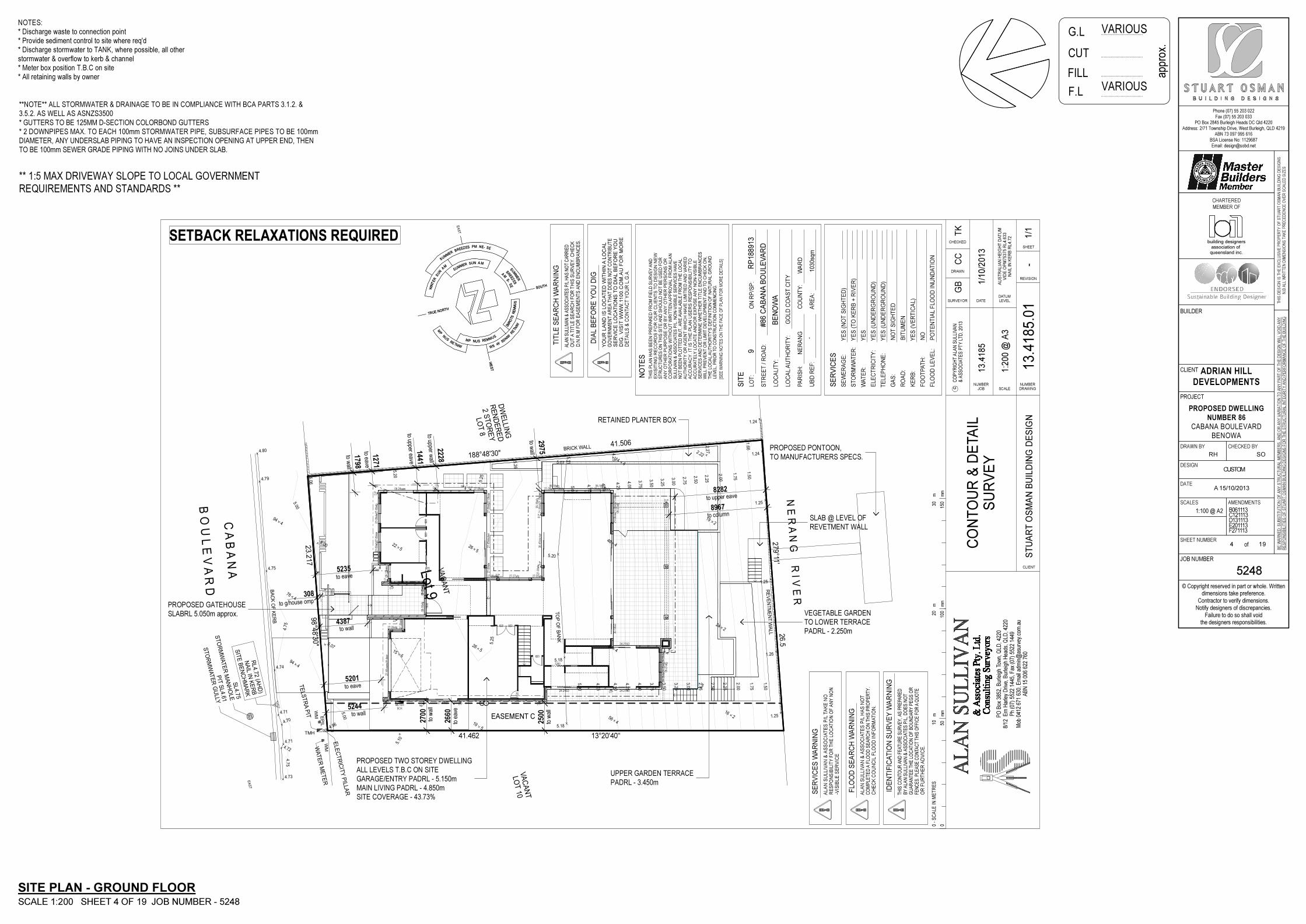
PROPOSED TWO STOREY DWELLINGALL LEVELS T.B.C ON SITEGARAGE/ENTRY PADRL - 5.150mMAIN LIVING PADRL - 4.850mSITE COVERAGE - 43.73%
UPPER GARDEN TERRACE
PADRL - 3.450m
VEGETABLE GARDENTO LOWER TERRACEPADRL - 2.250m
PROPOSED GATEHOUSESLABRL 5.050m approx.
SLAB @ LEVEL OFREVETMENT WALL
SIT
E B
EN
CH
MA
RK
NA
IL IN K
ER
BR
L4.7
2 (A
HD
)
ST
OR
MW
AT
ER
GU
LL Y
PIT
SL4.6
1
WMW
AT
ER
ME
TE
R
WM
T M H
TE
LS
TR
A P
IT EPI L
ELE
CT
RIC
ITY
PIL
LA
R
ST
OR
MW
AT
ER
MA
NH
OLE
SL4.7
5
4 . 8 0
4 . 7 9
4 . 7 5
4 . 7 4
4 . 7 1
4 . 70
4 . 7 1
4 . 7 2
4 . 7 3
5 . 0 7
5 . 2 0
5 . 1 8
5 . 1 8
1. 75
2. 00
5. 06
5. 20
5. 26
5. 11
4.25
2.27
1.66
1 . 2 5
1 . 2 6
1 . 2 5
1 . 2 5
1 . 2 4
1 . 2 4
5
1 9
5
2 6
5
2 65
2 2
5
1 5
5. 10
4 . 96
5 . 0 7
5 . 0 0
4
7 6
4
9 4
4
9 4
4
5 6
4
4 8
4
4 6
4
1 4
2 . 2 2
2
1 9
2
2 4
2
1 6
2.25
2.50
2.75
3.00
3.25
3. 50
3. 75
4. 00
4. 25
4. 50
4. 75
5.00
4. 75
1.50
5. 00
5. 25
050
mm
mm
100
mm
150
0 -
SC
ALE
IN
ME
TR
ES
10
mm
20
m30
CLIENT
ST
UA
RT
OS
MA
N B
UIL
DIN
G D
ES
IGN
SIT
E
LO
T:
AL
AN
SU
LL
IVA
N &
AS
SO
CIA
TE
S P
/L T
AK
E N
O
SE
RV
ICE
S W
AR
NIN
G
AL
AN
SU
LL
IVA
N &
AS
SO
CIA
TE
S P
/L H
AS
NO
T
IDE
NT
IFIC
AT
ION
SU
RV
EY
WA
RN
ING
TH
IS C
ON
TO
UR
AN
D F
EA
TU
RE
SU
RV
EY
, AS
PR
EP
AR
ED
FLO
OD
SE
AR
CH
WA
RN
ING
CHECKED
TK
SURVEYOR
CO
NT
OU
R &
DE
TA
IL
SU
RV
EY
1:2
00
@ A
3
CO
PY
RIG
HT
ALA
N S
ULLIV
AN
& A
SS
OC
IAT
ES
PT
Y L
TD
, 2013
c
PO Box
385
2, Burleigh To
wn, Q
LD, 4
220
8/12
Ern Harley Driv
e, Burleigh Hea
ds, Q
LD, 4
220
Ph (07) 552
2 14
45, F
ax (07
) 55
22 144
9Mob
041
2 67
1 63
0, Email a
dmin@as
urve
y.co
m.au
ABN 15 00
6 62
2 76
0
AU
ST
RA
LIA
N H
EIG
HT
DA
TU
MV
IDE
OP
M7
53
75
RL
4.6
33
NA
IL I
N K
ER
B R
L4
.72
TIT
LE
SE
AR
CH
WA
RN
ING
STR
EET / R
OAD
:
LO
CALIT
Y:
DRAWING
NUMBER
1-
REVISION
SHEET
SCALE
LEVEL
DATUM
JOB
NUMBER
DATE
1/1
0/2
01
3
DRAWN
GB
CC
13
.41
85
13
.41
85
.01
LO
CAL
AU
TH
OR
ITY:
PAR
ISH
:
UBD
REF:
ON
RP/S
P:
CO
UN
TY:
AR
EA:
9
#8
6 C
AB
AN
A B
OU
LE
VA
RD
RP
18
89
13
BE
NO
WA
GO
LD
CO
AST C
ITY
NER
AN
GW
AR
D
-1030sq
m
NO
TE
S
TH
IS P
LA
N H
AS
BE
EN
PR
EPA
RE
D F
RO
M F
IELD
SU
RV
EY
AN
DE
XIS
ITIN
G R
EC
OR
DS
FO
R O
UR
CLIE
NT
S T
O D
ES
IGN
NE
W
ST
RU
CT
UR
ES
ON
TH
IS S
ITE
AN
D S
HO
UL
D N
OT
BE
US
ED
FO
RA
NY
OT
HE
R P
UR
PO
SE
OR
BY
AN
Y O
TH
ER
PE
RS
ON
S O
R
CO
RP
OR
AT
ION
S W
ITH
OU
T W
RIT
TE
N A
PP
RO
VA
L F
RO
M A
LA
NS
UL
LIV
AN
& A
SS
OC
IAT
ES
P/L
. N
ON
-VIS
IBL
E S
ER
VIC
ES
HA
VE
NO
T B
EE
N P
LO
TT
ED
BU
T,
AR
E A
VA
ILA
BL
E F
RO
M T
HE
LO
CA
LA
UT
HO
RIT
Y O
R A
GE
NT
WH
ICH
HA
VE
LIM
ITIE
D A
ND
VA
RIE
DA
CC
UR
AC
Y. IT
IS
TH
E P
LA
N U
SE
RS
RE
SP
ON
SIB
ILIT
Y T
O
AC
CU
RA
TE
LY
LO
CA
TE
AN
D/O
R E
XP
OS
E A
NY
NO
N-V
ISIB
LE
SE
RV
ICE
S A
ND
DE
TE
RM
INE
WH
ET
HE
R T
ITLE
EN
CU
MB
RA
NC
ES
WIL
L P
RE
VE
NT O
R L
IMIT
DE
VE
LO
PM
EN
T A
ND
TO
CH
EC
K O
N,
TH
E L
OC
AL A
UT
HO
RIT
Y'S
DE
FIN
ITIO
N O
F N
AT
UR
AL G
RO
UN
DL
EV
EL
, P
RIO
R T
O C
ON
ST
RU
CT
ION
CO
MM
EN
CIN
G.
[SE
E W
AR
NIN
G N
OT
ES
ON
TH
E F
AC
E O
F P
LAN
FO
R M
OR
E D
ETA
ILS
]
AL
AN
SU
LL
IVA
N &
AS
SO
CIA
TE
S P
/L H
AS
NO
T C
AR
RIE
D
OU
T A
TIT
LE
SE
AR
CH
FO
R T
HIS
SU
RV
EY
. C
HE
CK
D.N
.R.M
FO
R E
AS
EM
EN
TS
AN
D E
NC
UM
BR
AN
CE
S.
RE
SP
ON
SIB
ILIT
Y F
OR
TH
E L
OC
AT
ION
OF
AN
Y N
ON
-VIS
IBL
E S
ER
VIC
E
CO
MP
LE
TE
D A
FLO
OD
SE
AR
CH
ON
TH
IS P
RO
PE
RT
Y.
CH
EC
K C
OU
NC
IL F
LO
OD
IN
FO
RM
AT
ION
.
BY
ALA
N S
ULLIV
AN
& A
SS
OC
IAT
ES
P/L
, D
OE
S N
OT
GU
AR
AN
TE
E T
HE
LO
CA
TIO
N O
F B
OU
ND
AR
Y P
EG
S O
RF
EN
CE
S.
PL
EA
SE
CO
NT
AC
T T
HIS
OF
FIC
E F
OR
A Q
UO
TE
OR
FU
RT
HE
R A
DV
ICE
.
SE
RV
ICE
S
SEW
ER
AG
E:
STO
RM
WATER
:
WATER
:
ELEC
TR
ICIT
Y:
TELEPH
ON
E:
GAS:
YES (N
OT S
IGH
TED
)
YES (TO
KER
B +
RIV
ER
)
YES
YES (U
ND
ER
GR
OU
ND
)
YES (U
ND
ER
GR
OU
ND
)
NO
T S
IGH
TED
RO
AD
:BIT
UM
EN
KER
B:
YES (VER
TIC
AL)
FO
OTPATH
:N
O
FLO
OD
LEVEL:
PO
TEN
TIA
L FLO
OD
IN
UN
DATIO
N
/1
DIA
L B
EF
OR
E Y
OU
DIG
YO
UR
LA
ND
IS
LO
CA
TE
D W
ITH
IN A
LO
CA
L
GO
VE
RN
ME
NT
AR
EA
TH
AT
DO
ES
NO
T C
ON
TR
IBU
TE
SE
RV
ICE
LO
CA
TIO
NS
TO
DIA
L B
EF
OR
E Y
OU
DIG
. V
ISIT
WW
W.1
10
0.C
OM
.AU
FO
R M
OR
E
DE
TA
ILS
& C
ON
TA
CT
YO
UR
L.G
.A.
23. 217
98° 48'30"
4 1 . 5 0 6
1 8 8 ° 4 8 ' 3 0 "
26.5
279°11'
41.462 13°20'40"
Lot 9
VA
CA
NT
EASEMENT C
LO
T 1
0V
AC
AN
T
LO
T 8
2 S
TO
RE
YR
EN
DE
RE
DD
WE
LLIN
G
C A
B A
N A
B O
U L
E V
A R
D
N E
R A
N G
R I V
E R
BA
CK
OF
KE
RB
4.75
5. 00
5. 25
1. 50
1.75
2. 00
2.25
2.50
2.75
3.00
3.25
3.50
3.75
4.00
4.25
4.50
4.75
5.00
TO
P O
F B
AN
K
RE
VE
NT
ME
NT
WA
LL
B R I C K W A L L
EAST
WEST
SUMME R
B RE E Z
E S P M N E - S E
WI NTER
SUN
AM
S UM M E R
S U N A M
SUMMER
BREEZES
A
MS-
SE
S
UMM
ER
ST
OR
MS WI
NT
ER
WIN
DSW-
SW
SUMMERSUNPM
WINTERSU
N
PM
S O U T H
T R U E N O R T H
EAST
WEST
SUMME R
B RE E Z
E S P M N E - S E
WI NTER
SUN
AM
S UM M E R
S U N A M
SUMMER
BREEZES
A
MS-
SE
S
UMM
ER
ST
OR
MS WI
NT
ER
WIN
DSW-
SW
SUMMERSUNPM
WINTERSU
N
PM
S O U T H
T R U E N O R T H
METER
BOX
GG
to w
all
to ea v e
to u p p e r e a v e
to u pp e r w
a ll
to wa
ll
t o w a l l
t o e a v e
t o e a v e
t o w a l l
to w
all
to e
ave
to w
all
t o c o l u m n
t o u p p e r e a v e
t o g / h o u s e o m p
tap
tap
tap
tap
tap
D.P
NOTES:* Discharge waste to connection point* Provide sediment control to site where req'd
* Meter box position T.B.C on site* All retaining walls by owner
* Discharge stormwater to TANK, where possible, all otherstormwater & overflow to kerb & channel
SITE PLAN - GROUND FLOOR
SCALE 1:200 SHEET 4 OF 19 JOB NUMBER - 5248
**NOTE** ALL STORMWATER & DRAINAGE TO BE IN COMPLIANCE WITH BCA PARTS 3.1.2. &3.5.2. AS WELL AS ASNZS3500
* GUTTERS TO BE 125MM D-SECTION COLORBOND GUTTERS* 2 DOWNPIPES MAX. TO EACH 100mm STORMWATER PIPE, SUBSURFACE PIPES TO BE 100mmDIAMETER, ANY UNDERSLAB PIPING TO HAVE AN INSPECTION OPENING AT UPPER END, THENTO BE 100mm SEWER GRADE PIPING WITH NO JOINS UNDER SLAB.
** 1:5 MAX DRIVEWAY SLOPE TO LOCAL GOVERNMENT
REQUIREMENTS AND STANDARDS **
................................
................................
................................
................................
CUT
F.L
FILL
VARIOUSG.L
approx.
SETBACK RELAXATIONS REQUIRED
VARIOUS
Phone (07) 55 203 022Fax (07) 55 203 033
PO Box 2845 Burleigh Heads DC Qld 4220Address: 2/71 Township Drive, West Burleigh, QLD 4219
ABN 73 097 995 616BSA License No: 1129687Email: [email protected]
© Copyright reserved in part or whole. Writtendimensions take preference.
Contractor to verify dimensions.Notify designers of discrepancies.
Failure to do so shall voidthe designers responsibilities.
TH
IS D
ES
IGN
IS
TH
E E
XC
LU
SIV
E P
RO
PE
RT
Y O
F S
TU
AR
T O
SM
AN
BU
ILD
ING
DE
SIG
NS
N.B
AL
L W
RIT
TE
N D
IME
NS
ION
S T
AK
E P
RE
CE
DE
NC
E O
VE
R S
CA
LE
D S
IZE
S
BE
WA
RN
ED
: S
UB
ST
ITU
TIO
N O
F A
NY
ST
RU
CT
UR
AL
ME
MB
ER
S,
AN
D O
R A
NY
VA
RIA
TIO
N T
O A
NY
PA
RT
OF
TH
E D
ES
IGN
WIL
L V
OID
AN
Y
RE
SP
ON
SIB
ILIT
IES
OF
ST
UA
RT
OS
MA
N B
UIL
DIN
G D
ES
IGN
S F
OR
TH
E S
TR
UC
TU
RA
L IN
TE
GR
ITY
AN
D P
ER
FO
RM
AN
CE
OF
TH
E B
UIL
DIN
G
CLIENT
PROJECT
JOB NUMBER
BUILDER
DRAWN BY CHECKED BY
DESIGN
DATE
SCALES AMENDMENTS
SHEET NUMBERof
CHARTERED
MEMBER OF
ADRIAN HILL
DEVELOPMENTS
PROPOSED DWELLING
NUMBER 86
CABANA BOULEVARDBENOWA
5248
RH
A 15/10/2013
B061113C121113D131113E201113F271113
SO
CUSTOM
1:100 @ A2
5 19
queensland inc.association of
building designers
1500
1200
920
920
820
620
820 820
820
27-27SD
27-4
8 pa
nelif
t doo
r
27-09afg 27-0
9afg
09-1
6afg
27-0
9afg
09-0
9afg
24-21SD24-24SD
06-18afg21-09alw21-09afg
06-18afg21-09alw21-09afg
21-0
9alw
21-0
9afg
06-1
8afg
27-0
9alw
30-4
5sta
cker
27-09alw 27-09alw27-27afg06-1
2aaw
06-24aaw 27-09alw
27-0
9alw
27-0
9alw
27-0
9afg
27-0
9afg
27-0
9afg
27-0
9alw
27-0
9alw
27-4
5sta
cker
24-21SD
06-2
7afg
21-0
9alw
21-0
9alw
21-0
9afg
30-1
8SD
24-0
9alw
24-0
9alw
24-0
9afg
06-2
7afg
12
12345678
W.M.PROV
DWPROV
1
2
3
4
5
6
7
8
9
10
11
12
13
1 2
D.P
D.P
D.P
D.P
D.P
D.P
D.P
D.P
D.P
D.P
D.P D.P D.P
D.P
1935
0
200
350
6190
900
350
2730
350
1490
6790
250
6040
250
900
350
1830
900
250
1750
9031
0090
3100
250
250
7190
350
2730
250
750
1000
9019
1090
1100
9011
0090
1910
250
250
6640
810
9031
6024
077
1025
0
250
1920
9090
090
3600
9085
031
6025
079
50
1935
0
1300
3690
900
1346
0
1100
3690
900
1750
350
4260
350
5250
350
1350
2200
200
1425
020
060
0020
0
1100
250
3440
250
1431
0
250
1800
9015
5025
013
860
250
200
2200
200
1300
250
1800
9011
1060
09060
015
0012
0096
6090
025
0
250
1270
9024
5090
2650
990
3160
250
7950
40
1010
27650
27650
990 9880 5000 6500 4290 990
5000 1000 15000200
2503500 600
901190 4000
2505000
2506000
2504650
350200 4300
200
600250
100090
210090
110090
4000250
5000250
6000250
4650350
2720
1450 14520350
10450 880
450250
700090
441090
2330250
11550 2100
2507000
904410
901100
901100
905810
904500
2503320
2501300 5700
904410
901100 1190
901800
902420
901500 4500
250880 2440
3200250
4400 1200100
90 2260 90 4340 890 1100 3000 1200250
4290 990 2440
600
1290
2000 350
400 1800
A
15
A
15
B
15
B
15
C
16
C
16
D
16
D
16
E
17
E
17
F
17
F
17
double sided cupd's
300mm high plinth
27-12 custom CSDfeature stoneworkto brickwork column
27-18 custom CSD
laundry chute
Low ceiling & door,mech. ventilation reqd.
feature stoneworkto blade wall
all toilets to haveconcealed cisterns
Wall hung vanity w. 150mmdeep mirrored cabinetw. recessed lighting
grated strip drain andniche to all showers
Wall hung vanity w. 150mmdeep mirrored cabinetw. recessed lighting
feature stoneworkto blade wall
line of deck above
line of deckabove
lined beambelow ceiling
1200mm high FGpool fence
blockwork retainedgarden bed @ levelof pool coping
tiled concrete pads
all toilets to haveconcealed cisterns
sauna unit installed tomanufacturers specs.
extent of voidextent of void
line of porch roof
1000mm highFG h/rail
feature stoneworkto blade wall
Refer detail
ALL robe / linen /store fit-outs tocabinetmakers specs.
ALL kitchen & laundryfitouts to cabinetmakersspecs.
renderedfoam blades
3000mm droppedceiling to Laundry
3000mm droppedceiling to Pantry
saunaunit
FW
ubo
BBQF
W
FW
pant
ry c
upd'
sM
WR
EF
.
OFFICE
LIBRARY
MEDIA /
KARAOKE
LOUNGE
FAMILY
DINING
OUTDOOR
LIVING
POOL15x2.2m
to pool builders specs.
GYMGARAGE
PORCH
FOYER
BED 6
BED 5
BUTLERS
PANTRY
LINEN
KITCHEN
fireplace & TV recess
ROBE
ROBE
garden
300mm o'hang
1200mm high FG pool fenceCOURTYARD
STORE
STORE
VOIDoverVOID over
STORE
STORE
turfed area
planter box
bulkhead over
METERBOX
GGgas hwstap
tap
tap
tap
tap
1000
mm
hig
h F
G h
andr
ail
1000mm high FG handrail
300m
m s
tep
bridgeabove
gate
gate
30-7
450
stac
ker
(OX
XX
XO
)
3020mm ceiling
3020mm ceiling
3020mm ceiling
3320mm ceiling
3320mm ceiling
3320mm ceiling
step
step
step
step
planter box
FW
D.P
NOTES:* Lift off hinges to WC door, as per BCA 3.8.3* Provide GPO & cold water provisions to DW space* ALL External and Internal doors & windows to bemeasured on site and confirmed by builder* Sarking to external walls* Insulation to ceiling (living only) R2.5 batts* All windows & SGD to be tinted* Mechanically vent rooms without natural ventilation* All shower roses to be AAA rated* Maximum water supply pressure not to exceed 500kpaat any outlet* Hot water system shall be heat pump, solar or gas*Water supply outlets to have WELs rating* Toilet cisterns to have dual flush. 6/3 Litre* ALL handrails to be 1000mm above finished floor level* Bedroom windows w. 2m fall height from FL to groundbelow must comply with N.C.C 3.9.2.5. To be fitted withnon-removable screens or restricted to 125mm opening
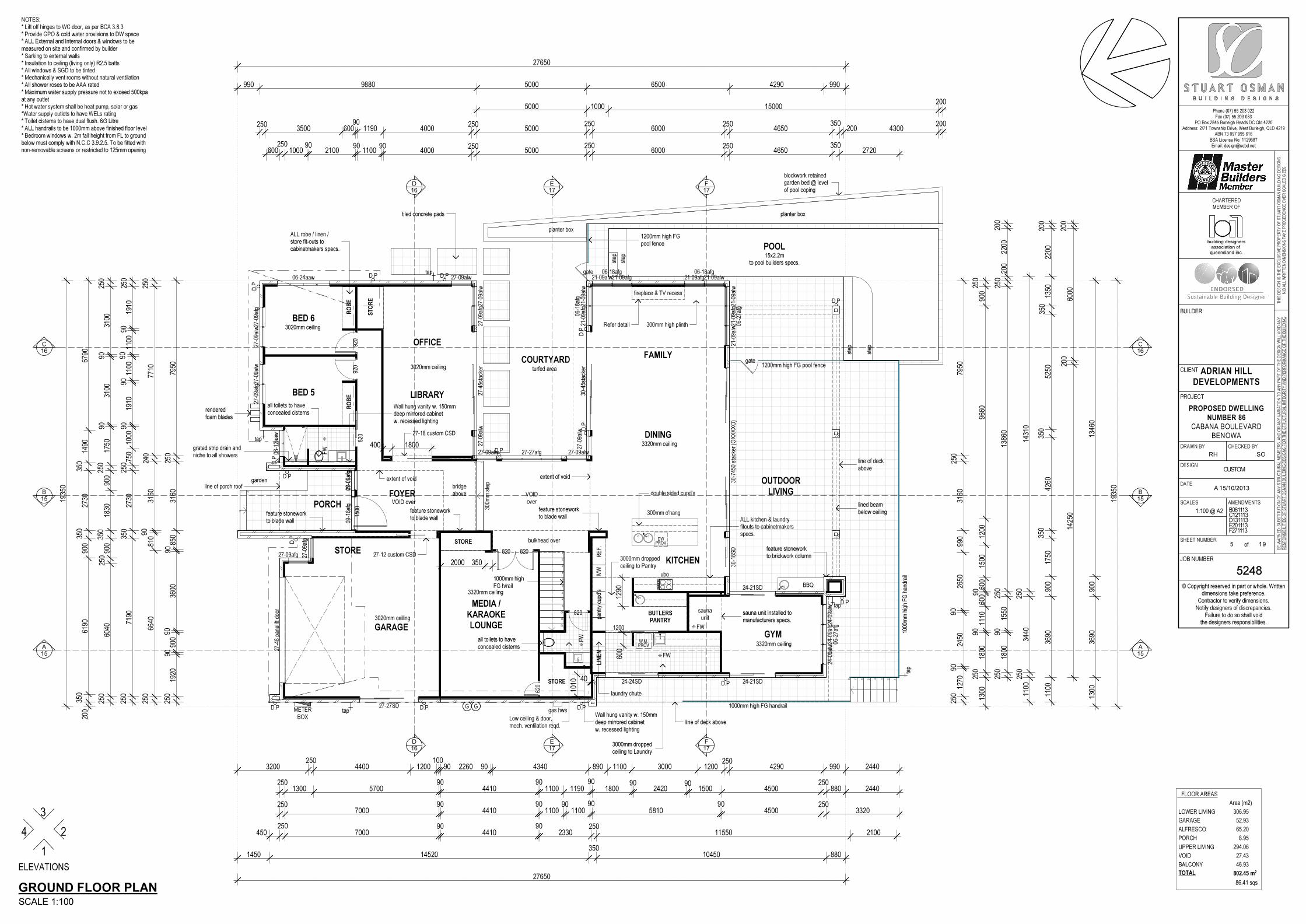
FLOOR AREAS
01 LOWER LIVING
02 GARAGE
03 ALFRESCO
04 PORCH
05 UPPER LIVING
06 VOID
07 BALCONY
Area (m2)
306.95
52.93
65.20
8.95
294.06
27.43
46.93
802.45 m2
GROUND FLOOR PLAN
SCALE 1:100
ELEVATIONS
4
3
2
1
TOTAL
86.41 sqs

Phone (07) 55 203 022Fax (07) 55 203 033
PO Box 2845 Burleigh Heads DC Qld 4220Address: 2/71 Township Drive, West Burleigh, QLD 4219
ABN 73 097 995 616BSA License No: 1129687Email: [email protected]
© Copyright reserved in part or whole. Writtendimensions take preference.
Contractor to verify dimensions.Notify designers of discrepancies.
Failure to do so shall voidthe designers responsibilities.
TH
IS D
ES
IGN
IS
TH
E E
XC
LU
SIV
E P
RO
PE
RT
Y O
F S
TU
AR
T O
SM
AN
BU
ILD
ING
DE
SIG
NS
N.B
AL
L W
RIT
TE
N D
IME
NS
ION
S T
AK
E P
RE
CE
DE
NC
E O
VE
R S
CA
LE
D S
IZE
S
BE
WA
RN
ED
: S
UB
ST
ITU
TIO
N O
F A
NY
ST
RU
CT
UR
AL
ME
MB
ER
S,
AN
D O
R A
NY
VA
RIA
TIO
N T
O A
NY
PA
RT
OF
TH
E D
ES
IGN
WIL
L V
OID
AN
Y
RE
SP
ON
SIB
ILIT
IES
OF
ST
UA
RT
OS
MA
N B
UIL
DIN
G D
ES
IGN
S F
OR
TH
E S
TR
UC
TU
RA
L IN
TE
GR
ITY
AN
D P
ER
FO
RM
AN
CE
OF
TH
E B
UIL
DIN
G
CLIENT
PROJECT
JOB NUMBER
BUILDER
DRAWN BY CHECKED BY
DESIGN
DATE
SCALES AMENDMENTS
SHEET NUMBERof
CHARTERED
MEMBER OF
ADRIAN HILL
DEVELOPMENTS
PROPOSED DWELLING
NUMBER 86
CABANA BOULEVARDBENOWA
5248
RH
A 15/10/2013
B061113C121113D131113E201113F271113
SO
CUSTOM
1:100 @ A2
6 19
queensland inc.association of
building designers
920
820
820
920
920
920
920
820
T
04-2
7afg
14-0
9afg
14-0
9afg
14-18alw 13-27alw24-24SD
24-09alw24-09afg24-09alw 24-27SD
24-0
9alw
24-0
9alw
24-3
6SD
24-3
6SD
24-3
6SD
24-0
9alw
24-0
9afg
24-0
9alw
24-0
9alw
24-2
7afg
24-0
9alw
24-09alw
24-27afg24-09alw
18-21afg
04-15afg04-15afg
06-3
6afg
06-09alw06-15afg
8
9
10
11
12
13
15
16
17
18
19
20
21
D.P
D.P
D.P
D.P
D.P
D.P
D.P
D.P
D.P D.P D.P
D.P
17-09afg17-16afg
A
15
A
15
B
15
B
15
C
16
C
16
D
16
D
16
E
17
E
17
F
17
F
17
45045
0
450
20690
20690
1001150 4440 4400 10600 1500
600 6500 3500 1150350
1150150
4040250
4400150
1830 1100240
324090
3800150
1500
1505190
2504400
1501150
901690
240500 2240 500
903800
150
2000
2000
2504000 1380 5220 1890
2401500
905970
150
600 600350
6720350
2170350
9550 1000
1503500 600
903620 2290
901800 90
1501500
901000 3970 1000
1501000
150600 3500 600
903620 1100
901100
90600 2040 90 900 5970
150790 990
1502910 90 1100
90 1001000 5600 1700
901650
905970
1501150
350
1935
0
1935
0
700
600
3250
6520
7130
1150
60015
047
1090
1650
9027
3035
080
3025
0
3250
150
1460
9016
5090
2730
350
6980
150
1150
60015
061
9035
031
6025
079
50
1300
1690
011
50
4790
900
1750
350
4260
350
5250
350
1100
150
1590
9032
0090
3200
9015
9090
6660
150
1100
150
3570
9012
2090
1220
9035
7090
1070
9045
1090
900
150
1150
1300
150
3570
9011
4029
011
0035
031
6024
011
6090
027
0019
0015
0
700
1290
150
3110
1200
1190
350
3160
250
6800
18 degree flat profile concreteroof tiles, sarking under
Stramit colorbond fascias,gutters & downpipes
Stramit colorbond fascias,gutters & downpipes
feature stoneworkto blade wall
laundry chute
feature stoneworkto blade wall
feature stoneworkto blade wall
feature stoneworkto blade wall
BALCONY
2400mm high walls w.FG panels above
18 degree flat profile concreteroof tiles, sarking under
approx. 51 degree flat profile concreteroof tiles, sarking under
approx. 44 degree flat profile concreteroof tiles, sarking under
1300mm high wall,alum. louvres above
mech. ventrequired
mech. ventrequired
solar tubeskylight
50mm stepdownto wet area
Wash tub withtiled floor & walls
Wall hung vanity w. 150mmdeep mirrored cabinetw. recessed lighting
all toilets to haveconcealed cisterns
grated strip drain andniche to all showers
grated strip drain andniche to all showers
1100mm high wall
1 degree colorbond kliplok roof sheeting
600mm widebox gutter
Stramit colorbond capping to topof all parapet walls, 1:100 fall backinto roof area, refer Parapet Details
Stramit colorbond capping to topof all parapet walls, 1:100 fall backinto roof area, refer Parapet Details
high windowabove mirror cabinet
high windowabove mirror cabinet
provide 2x floorwastes to tiled deck
Framed & renderedbox beam above
Lintel in ceiling space,above front elevationupper level windows
Lintel in ceiling space,above front elevationupper level windows
ROBE
BED 4
MASTER
SUITE
RUMPUS
VOID
BALCONY
1000
mm
hig
h F
G h
/rai
l
roof
fall
roof fall
roof fall
FW
FW
LINEN
LINEN
roof fall
W.I.RART STUDIO
BED 2
FW
dres
ser
/ ben
ch s
eat
W.I.R
alum. louvre screens
alum. louvre screens
VOID
desk
RETREAT
desk
FW
BED 3
W.I.R
desk
1000
mm
hig
h F
G h
/rai
l
1000
mm
hig
h F
G h
/rai
l
BALCONY
M
FW
1000
mm
hig
h F
G h
/rai
l
shel
ves
roof fall
FW FW
shelves
Free standing
bath
D.P
D.P
D.P
D.P
D.P
D.P
NOTES:* Lift off hinges to WC door, as per BCA 3.8.3* Provide GPO & cold water provisions to DW space* ALL External and Internal doors & windows to bemeasured on site and confirmed by builder* Sarking to external walls* Insulation to ceiling (living only) R2.5 batts* All windows & SGD to be tinted* Mechanically vent rooms without natural ventilation* All shower roses to be AAA rated* Maximum water supply pressure not to exceed 500kpaat any outlet* Hot water system shall be heat pump, solar or gas*Water supply outlets to have WELs rating* Toilet cisterns to have dual flush. 6/3 Litre* ALL handrails to be 1000mm above finished floor level* Bedroom windows w. 2m fall height from FL to groundbelow must comply with N.C.C 3.9.2.5. To be fitted withnon-removable screens or restricted to 125mm opening
FIRST FLOOR PLAN
SCALE 1:100
ELEVATIONS
4
3
2
1
Phone (07) 55 203 022Fax (07) 55 203 033
PO Box 2845 Burleigh Heads DC Qld 4220Address: 2/71 Township Drive, West Burleigh, QLD 4219
ABN 73 097 995 616BSA License No: 1129687Email: [email protected]
© Copyright reserved in part or whole. Writtendimensions take preference.
Contractor to verify dimensions.Notify designers of discrepancies.
Failure to do so shall voidthe designers responsibilities.
TH
IS D
ES
IGN
IS
TH
E E
XC
LU
SIV
E P
RO
PE
RT
Y O
F S
TU
AR
T O
SM
AN
BU
ILD
ING
DE
SIG
NS
N.B
AL
L W
RIT
TE
N D
IME
NS
ION
S T
AK
E P
RE
CE
DE
NC
E O
VE
R S
CA
LE
D S
IZE
S
BE
WA
RN
ED
: S
UB
ST
ITU
TIO
N O
F A
NY
ST
RU
CT
UR
AL
ME
MB
ER
S,
AN
D O
R A
NY
VA
RIA
TIO
N T
O A
NY
PA
RT
OF
TH
E D
ES
IGN
WIL
L V
OID
AN
Y
RE
SP
ON
SIB
ILIT
IES
OF
ST
UA
RT
OS
MA
N B
UIL
DIN
G D
ES
IGN
S F
OR
TH
E S
TR
UC
TU
RA
L IN
TE
GR
ITY
AN
D P
ER
FO
RM
AN
CE
OF
TH
E B
UIL
DIN
G
CLIENT
PROJECT
JOB NUMBER
BUILDER
DRAWN BY CHECKED BY
DESIGN
DATE
SCALES AMENDMENTS
SHEET NUMBERof
CHARTERED
MEMBER OF
ADRIAN HILL
DEVELOPMENTS
PROPOSED DWELLING
NUMBER 86
CABANA BOULEVARDBENOWA
5248
RH
A 15/10/2013
B061113C121113D131113E201113F271113
SO
CUSTOM
1:100 @ A2
7 19
queensland inc.association of
building designers
D.P
D.P
D.P
D.P
A
15
A
15
B
15
B
15
C
16
C
16
D
16
D
16
E
17
E
17
F
17
F
17
740
600
600
600
600
600
600
600
600
1850
1750
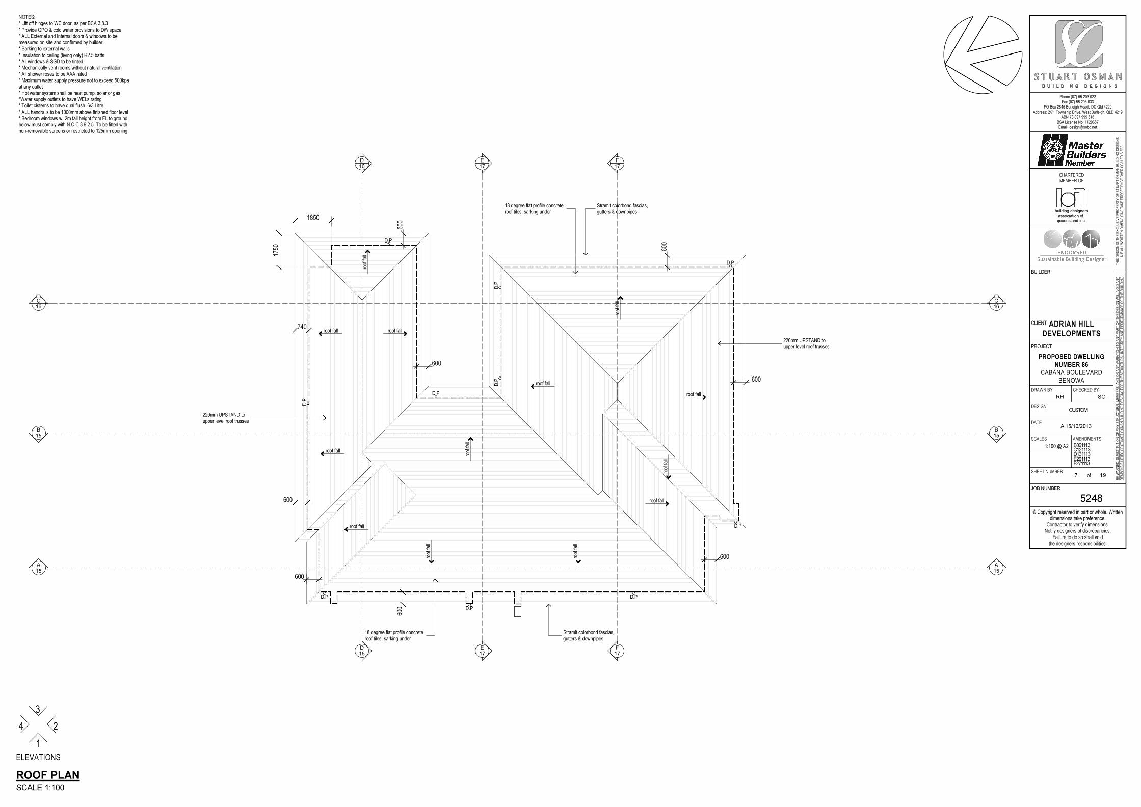
18 degree flat profile concreteroof tiles, sarking under
18 degree flat profile concreteroof tiles, sarking under
Stramit colorbond fascias,gutters & downpipes
Stramit colorbond fascias,gutters & downpipes
220mm UPSTAND toupper level roof trusses
220mm UPSTAND toupper level roof trusses
roof
fall
roof
fall
roof
fall
roof
fall
roof
fall
roof
fall
roof fall
roof fall
roof fall
roof fall
roof fall
roof fall
roof fall
D.P
D.P
D.P
D.P
D.P
D.P
NOTES:* Lift off hinges to WC door, as per BCA 3.8.3* Provide GPO & cold water provisions to DW space* ALL External and Internal doors & windows to bemeasured on site and confirmed by builder* Sarking to external walls* Insulation to ceiling (living only) R2.5 batts* All windows & SGD to be tinted* Mechanically vent rooms without natural ventilation* All shower roses to be AAA rated* Maximum water supply pressure not to exceed 500kpaat any outlet* Hot water system shall be heat pump, solar or gas*Water supply outlets to have WELs rating* Toilet cisterns to have dual flush. 6/3 Litre* ALL handrails to be 1000mm above finished floor level* Bedroom windows w. 2m fall height from FL to groundbelow must comply with N.C.C 3.9.2.5. To be fitted withnon-removable screens or restricted to 125mm opening
ROOF PLAN
SCALE 1:100
ELEVATIONS
4
3
2
1
Phone (07) 55 203 022Fax (07) 55 203 033
PO Box 2845 Burleigh Heads DC Qld 4220Address: 2/71 Township Drive, West Burleigh, QLD 4219
ABN 73 097 995 616BSA License No: 1129687Email: [email protected]
© Copyright reserved in part or whole. Writtendimensions take preference.
Contractor to verify dimensions.Notify designers of discrepancies.
Failure to do so shall voidthe designers responsibilities.
TH
IS D
ES
IGN
IS
TH
E E
XC
LU
SIV
E P
RO
PE
RT
Y O
F S
TU
AR
T O
SM
AN
BU
ILD
ING
DE
SIG
NS
N.B
AL
L W
RIT
TE
N D
IME
NS
ION
S T
AK
E P
RE
CE
DE
NC
E O
VE
R S
CA
LE
D S
IZE
S
BE
WA
RN
ED
: S
UB
ST
ITU
TIO
N O
F A
NY
ST
RU
CT
UR
AL
ME
MB
ER
S,
AN
D O
R A
NY
VA
RIA
TIO
N T
O A
NY
PA
RT
OF
TH
E D
ES
IGN
WIL
L V
OID
AN
Y
RE
SP
ON
SIB
ILIT
IES
OF
ST
UA
RT
OS
MA
N B
UIL
DIN
G D
ES
IGN
S F
OR
TH
E S
TR
UC
TU
RA
L IN
TE
GR
ITY
AN
D P
ER
FO
RM
AN
CE
OF
TH
E B
UIL
DIN
G
CLIENT
PROJECT
JOB NUMBER
BUILDER
DRAWN BY CHECKED BY
DESIGN
DATE
SCALES AMENDMENTS
SHEET NUMBERof
CHARTERED
MEMBER OF
ADRIAN HILL
DEVELOPMENTS
PROPOSED DWELLING
NUMBER 86
CABANA BOULEVARDBENOWA
5248
RH
A 15/10/2013
B061113C121113D131113E201113F271113
SO
CUSTOM
1:100 @ A2
8 19
queensland inc.association of
building designers
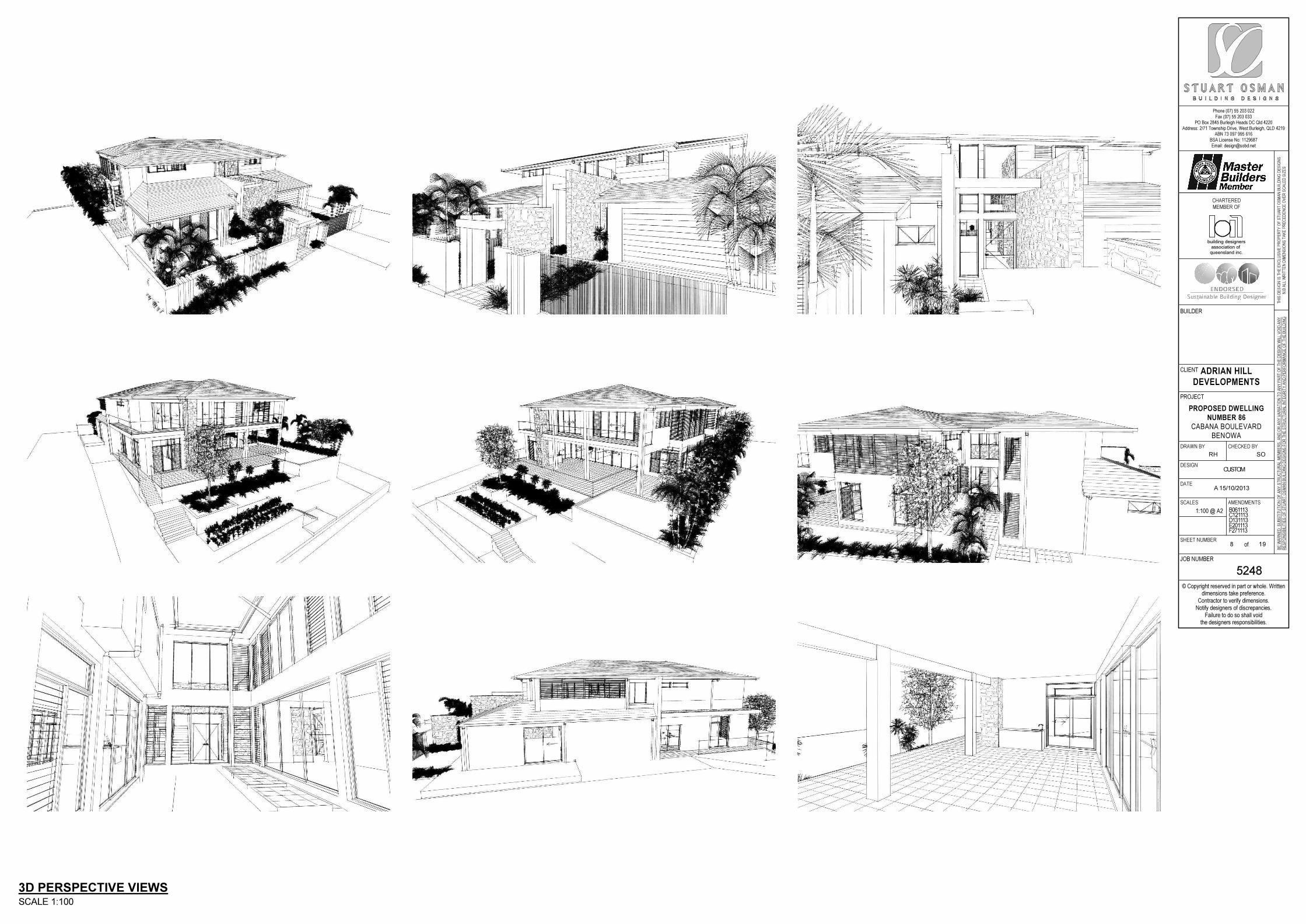
3D PERSPECTIVE VIEWS
SCALE 1:100
Phone (07) 55 203 022Fax (07) 55 203 033
PO Box 2845 Burleigh Heads DC Qld 4220Address: 2/71 Township Drive, West Burleigh, QLD 4219
ABN 73 097 995 616BSA License No: 1129687Email: [email protected]
© Copyright reserved in part or whole. Writtendimensions take preference.
Contractor to verify dimensions.Notify designers of discrepancies.
Failure to do so shall voidthe designers responsibilities.
TH
IS D
ES
IGN
IS
TH
E E
XC
LU
SIV
E P
RO
PE
RT
Y O
F S
TU
AR
T O
SM
AN
BU
ILD
ING
DE
SIG
NS
N.B
AL
L W
RIT
TE
N D
IME
NS
ION
S T
AK
E P
RE
CE
DE
NC
E O
VE
R S
CA
LE
D S
IZE
S
BE
WA
RN
ED
: S
UB
ST
ITU
TIO
N O
F A
NY
ST
RU
CT
UR
AL
ME
MB
ER
S,
AN
D O
R A
NY
VA
RIA
TIO
N T
O A
NY
PA
RT
OF
TH
E D
ES
IGN
WIL
L V
OID
AN
Y
RE
SP
ON
SIB
ILIT
IES
OF
ST
UA
RT
OS
MA
N B
UIL
DIN
G D
ES
IGN
S F
OR
TH
E S
TR
UC
TU
RA
L IN
TE
GR
ITY
AN
D P
ER
FO
RM
AN
CE
OF
TH
E B
UIL
DIN
G
CLIENT
PROJECT
JOB NUMBER
BUILDER
DRAWN BY CHECKED BY
DESIGN
DATE
SCALES AMENDMENTS
SHEET NUMBERof
CHARTERED
MEMBER OF
ADRIAN HILL
DEVELOPMENTS
PROPOSED DWELLING
NUMBER 86
CABANA BOULEVARDBENOWA
5248
RH
A 15/10/2013
B061113C121113D131113E201113F271113
SO
CUSTOM
1:100 @ A2
9 19
queensland inc.association of
building designers
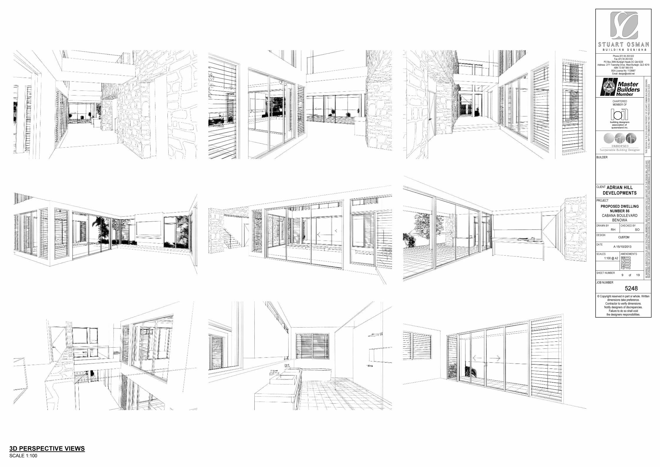
3D PERSPECTIVE VIEWS
SCALE 1:100
Phone (07) 55 203 022Fax (07) 55 203 033
PO Box 2845 Burleigh Heads DC Qld 4220Address: 2/71 Township Drive, West Burleigh, QLD 4219
ABN 73 097 995 616BSA License No: 1129687Email: [email protected]
© Copyright reserved in part or whole. Writtendimensions take preference.
Contractor to verify dimensions.Notify designers of discrepancies.
Failure to do so shall voidthe designers responsibilities.
TH
IS D
ES
IGN
IS
TH
E E
XC
LU
SIV
E P
RO
PE
RT
Y O
F S
TU
AR
T O
SM
AN
BU
ILD
ING
DE
SIG
NS
N.B
AL
L W
RIT
TE
N D
IME
NS
ION
S T
AK
E P
RE
CE
DE
NC
E O
VE
R S
CA
LE
D S
IZE
S
BE
WA
RN
ED
: S
UB
ST
ITU
TIO
N O
F A
NY
ST
RU
CT
UR
AL
ME
MB
ER
S,
AN
D O
R A
NY
VA
RIA
TIO
N T
O A
NY
PA
RT
OF
TH
E D
ES
IGN
WIL
L V
OID
AN
Y
RE
SP
ON
SIB
ILIT
IES
OF
ST
UA
RT
OS
MA
N B
UIL
DIN
G D
ES
IGN
S F
OR
TH
E S
TR
UC
TU
RA
L IN
TE
GR
ITY
AN
D P
ER
FO
RM
AN
CE
OF
TH
E B
UIL
DIN
G
CLIENT
PROJECT
JOB NUMBER
BUILDER
DRAWN BY CHECKED BY
DESIGN
DATE
SCALES AMENDMENTS
SHEET NUMBERof
CHARTERED
MEMBER OF
ADRIAN HILL
DEVELOPMENTS
PROPOSED DWELLING
NUMBER 86
CABANA BOULEVARDBENOWA
5248
RH
A 15/10/2013
B061113C121113D131113E201113F271113
SO
CUSTOM
1:100 @ A2
10 19
queensland inc.association of
building designers
3320
475
2720
3020
475
2720
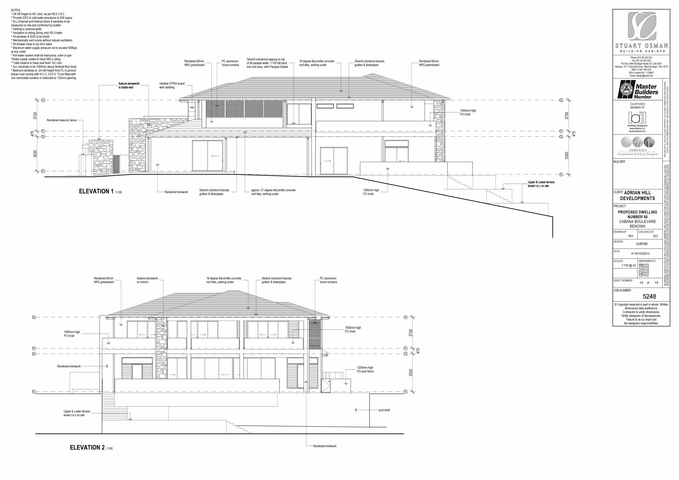
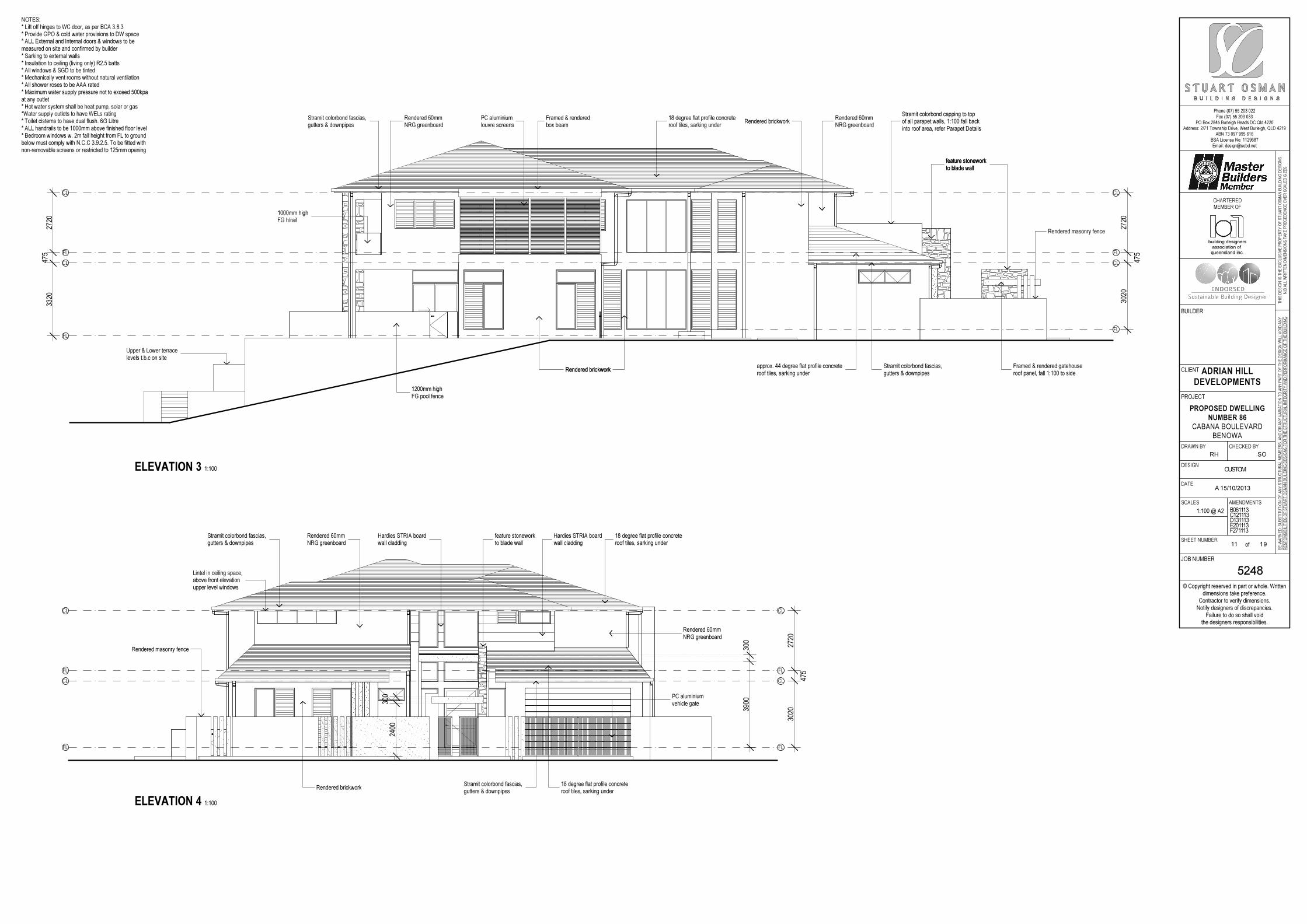
Stramit colorbond capping to topof all parapet walls, 1:100 fall backinto roof area, refer Parapet Details
approx. 51 degree flat profile concreteroof tiles, sarking under
Stramit colorbond fascias,gutters & downpipes
Rendered brickwork
18 degree flat profile concreteroof tiles, sarking under
Stramit colorbond fascias,gutters & downpipes
Rendered 60mmNRG greenboard
Rendered 60mmNRG greenboard
PC aluminiumlouvre screens
feature stoneworkto blade wallfeature stoneworkto blade wall
1000mm highFG h/rail
1000mm highFG h/rail
Upper & Lower terracelevels t.b.c on siteUpper & Lower terracelevels t.b.c on site
Hardies STRIA boardwall cladding
Rendered masonry fence
FL
FL
FL FL
CL CL
CL CL
ELEVATION 1 1:100
3320
475
2720
Rendered brickwork
18 degree flat profile concreteroof tiles, sarking under
Stramit colorbond fascias,gutters & downpipes
Rendered 60mmNRG greenboard
PC aluminiumlouvre screens
1000mm highFG h/rail
Upper & Lower terracelevels t.b.c on site
feature stoneworkto column
1200mm highFG pool fence
pool shell
Rendered brickwork
1000mm highFG h/rail
FL FL
FL FL
CL CL
CL CL
ELEVATION 2 1:100
NOTES:* Lift off hinges to WC door, as per BCA 3.8.3* Provide GPO & cold water provisions to DW space* ALL External and Internal doors & windows to bemeasured on site and confirmed by builder* Sarking to external walls* Insulation to ceiling (living only) R2.5 batts* All windows & SGD to be tinted* Mechanically vent rooms without natural ventilation* All shower roses to be AAA rated* Maximum water supply pressure not to exceed 500kpaat any outlet* Hot water system shall be heat pump, solar or gas*Water supply outlets to have WELs rating* Toilet cisterns to have dual flush. 6/3 Litre* ALL handrails to be 1000mm above finished floor level* Bedroom windows w. 2m fall height from FL to groundbelow must comply with N.C.C 3.9.2.5. To be fitted withnon-removable screens or restricted to 125mm opening
Phone (07) 55 203 022Fax (07) 55 203 033
PO Box 2845 Burleigh Heads DC Qld 4220Address: 2/71 Township Drive, West Burleigh, QLD 4219
ABN 73 097 995 616BSA License No: 1129687Email: [email protected]
© Copyright reserved in part or whole. Writtendimensions take preference.
Contractor to verify dimensions.Notify designers of discrepancies.
Failure to do so shall voidthe designers responsibilities.
TH
IS D
ES
IGN
IS
TH
E E
XC
LU
SIV
E P
RO
PE
RT
Y O
F S
TU
AR
T O
SM
AN
BU
ILD
ING
DE
SIG
NS
N.B
AL
L W
RIT
TE
N D
IME
NS
ION
S T
AK
E P
RE
CE
DE
NC
E O
VE
R S
CA
LE
D S
IZE
S
BE
WA
RN
ED
: S
UB
ST
ITU
TIO
N O
F A
NY
ST
RU
CT
UR
AL
ME
MB
ER
S,
AN
D O
R A
NY
VA
RIA
TIO
N T
O A
NY
PA
RT
OF
TH
E D
ES
IGN
WIL
L V
OID
AN
Y
RE
SP
ON
SIB
ILIT
IES
OF
ST
UA
RT
OS
MA
N B
UIL
DIN
G D
ES
IGN
S F
OR
TH
E S
TR
UC
TU
RA
L IN
TE
GR
ITY
AN
D P
ER
FO
RM
AN
CE
OF
TH
E B
UIL
DIN
G
CLIENT
PROJECT
JOB NUMBER
BUILDER
DRAWN BY CHECKED BY
DESIGN
DATE
SCALES AMENDMENTS
SHEET NUMBERof
CHARTERED
MEMBER OF
ADRIAN HILL
DEVELOPMENTS
PROPOSED DWELLING
NUMBER 86
CABANA BOULEVARDBENOWA
5248
RH
A 15/10/2013
B061113C121113D131113E201113F271113
SO
CUSTOM
1:100 @ A2
11 19
queensland inc.association of
building designers
3020
475
2720
3320
475
2720
Stramit colorbond capping to topof all parapet walls, 1:100 fall backinto roof area, refer Parapet Details
approx. 44 degree flat profile concreteroof tiles, sarking under
Stramit colorbond fascias,gutters & downpipes
Rendered brickwork
18 degree flat profile concreteroof tiles, sarking under
Stramit colorbond fascias,gutters & downpipes
Rendered 60mmNRG greenboard
PC aluminiumlouvre screens
feature stoneworkto blade wall
1000mm highFG h/rail
1200mm highFG pool fence
Upper & Lower terracelevels t.b.c on site
Rendered masonry fence
Rendered brickwork
feature stoneworkto blade wall
Framed & rendered gatehouseroof panel, fall 1:100 to side
Rendered 60mmNRG greenboard
Rendered brickworkFramed & renderedbox beam
FL
FL
FL FL
CL CL
CL CL
ELEVATION 3 1:100
3020
475
2720
2400
300
3900
300
Stramit colorbond fascias,gutters & downpipes
Rendered brickwork
Rendered 60mmNRG greenboard
Hardies STRIA boardwall cladding
Rendered masonry fence
feature stoneworkto blade wall
Hardies STRIA boardwall cladding
18 degree flat profile concreteroof tiles, sarking under
Stramit colorbond fascias,gutters & downpipes
18 degree flat profile concreteroof tiles, sarking under
PC aluminiumvehicle gate
Rendered 60mmNRG greenboard
Lintel in ceiling space,above front elevationupper level windows
FL FL
FL FL
CL CL
CL CL
ELEVATION 4 1:100
NOTES:* Lift off hinges to WC door, as per BCA 3.8.3* Provide GPO & cold water provisions to DW space* ALL External and Internal doors & windows to bemeasured on site and confirmed by builder* Sarking to external walls* Insulation to ceiling (living only) R2.5 batts* All windows & SGD to be tinted* Mechanically vent rooms without natural ventilation* All shower roses to be AAA rated* Maximum water supply pressure not to exceed 500kpaat any outlet* Hot water system shall be heat pump, solar or gas*Water supply outlets to have WELs rating* Toilet cisterns to have dual flush. 6/3 Litre* ALL handrails to be 1000mm above finished floor level* Bedroom windows w. 2m fall height from FL to groundbelow must comply with N.C.C 3.9.2.5. To be fitted withnon-removable screens or restricted to 125mm opening
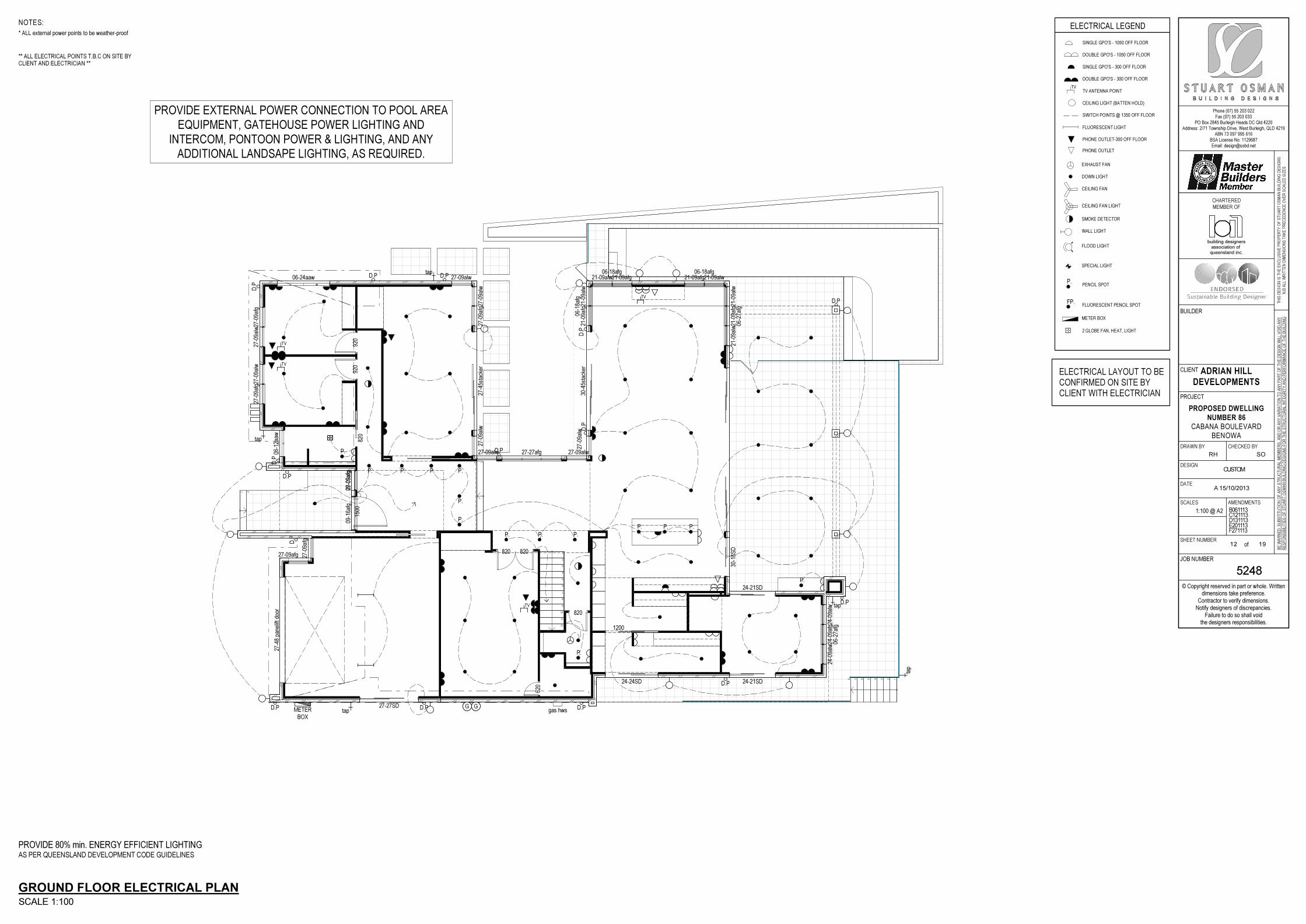
Phone (07) 55 203 022Fax (07) 55 203 033
PO Box 2845 Burleigh Heads DC Qld 4220Address: 2/71 Township Drive, West Burleigh, QLD 4219
ABN 73 097 995 616BSA License No: 1129687Email: [email protected]
© Copyright reserved in part or whole. Writtendimensions take preference.
Contractor to verify dimensions.Notify designers of discrepancies.
Failure to do so shall voidthe designers responsibilities.
TH
IS D
ES
IGN
IS
TH
E E
XC
LU
SIV
E P
RO
PE
RT
Y O
F S
TU
AR
T O
SM
AN
BU
ILD
ING
DE
SIG
NS
N.B
AL
L W
RIT
TE
N D
IME
NS
ION
S T
AK
E P
RE
CE
DE
NC
E O
VE
R S
CA
LE
D S
IZE
S
BE
WA
RN
ED
: S
UB
ST
ITU
TIO
N O
F A
NY
ST
RU
CT
UR
AL
ME
MB
ER
S,
AN
D O
R A
NY
VA
RIA
TIO
N T
O A
NY
PA
RT
OF
TH
E D
ES
IGN
WIL
L V
OID
AN
Y
RE
SP
ON
SIB
ILIT
IES
OF
ST
UA
RT
OS
MA
N B
UIL
DIN
G D
ES
IGN
S F
OR
TH
E S
TR
UC
TU
RA
L IN
TE
GR
ITY
AN
D P
ER
FO
RM
AN
CE
OF
TH
E B
UIL
DIN
G
CLIENT
PROJECT
JOB NUMBER
BUILDER
DRAWN BY CHECKED BY
DESIGN
DATE
SCALES AMENDMENTS
SHEET NUMBERof
CHARTERED
MEMBER OF
ADRIAN HILL
DEVELOPMENTS
PROPOSED DWELLING
NUMBER 86
CABANA BOULEVARDBENOWA
5248
RH
A 15/10/2013
B061113C121113D131113E201113F271113
SO
CUSTOM
1:100 @ A2
12 19
queensland inc.association of
building designers
1500
1200
920
920
820
620
820 820
820
27-27SD
27-4
8 pa
nelif
t doo
r
27-09afg 27-0
9afg
09-1
6afg
27-0
9afg
09-0
9afg
24-21SD24-24SD
06-18afg21-09alw21-09afg
06-18afg21-09alw21-09afg
21-0
9alw
21-0
9afg
06-1
8afg
27-0
9alw
30-4
5sta
cker
27-09alw 27-09alw27-27afg06-1
2aaw
06-24aaw 27-09alw
27-0
9alw
27-0
9alw
27-0
9afg
27-0
9afg
27-0
9afg
27-0
9alw
27-0
9alw
27-4
5sta
cker
24-21SD
06-2
7afg
21-0
9alw
21-0
9alw
21-0
9afg
30-1
8SD
24-0
9alw
24-0
9alw
24-0
9afg
06-2
7afg
12
12345678
1
2
3
4
5
6
7
8
9
10
11
12
13
1 2
D.P
D.P
D.P
D.P
D.P
D.P
D.P
D.P
D.P
D.P
D.P D.P D.P
D.P
P.
P. P. P.P.
P.P. P. P.
P.
P. P.P.
TV
TV
TV
TV
METERBOX
GG
P.
gas hwstap
tap
tap
tap
tap
P.
D.P
GROUND FLOOR ELECTRICAL PLAN
SCALE 1:100
PROVIDE 80% min. ENERGY EFFICIENT LIGHTING
AS PER QUEENSLAND DEVELOPMENT CODE GUIDELINES
CLIENT WITH ELECTRICIAN
CONFIRMED ON SITE BY
ELECTRICAL LAYOUT TO BE
P.
ELECTRICAL LEGEND
TV
CEILING FAN LIGHT
PHONE OUTLET
2 GLOBE FAN, HEAT, LIGHT
METER BOX
SINGLE GPO'S - 1050 OFF FLOOR
SINGLE GPO'S - 300 OFF FLOOR
DOUBLE GPO'S - 300 OFF FLOOR
TV ANTENNA POINT
EXHAUST FAN
FLUORESCENT LIGHT
PHONE OUTLET-300 OFF FLOOR
CEILING FAN
DOWN LIGHT
WALL LIGHT
SMOKE DETECTOR
FLOOD LIGHT
PENCIL SPOT
SPECIAL LIGHT
SWITCH POINTS @ 1350 OFF FLOOR
DOUBLE GPO'S - 1050 OFF FLOOR
CEILING LIGHT (BATTEN HOLD)
NOTES:
* ALL external power points to be weather-proof
** ALL ELECTRICAL POINTS T.B.C ON SITE BYCLIENT AND ELECTRICIAN **
FP.FLUORESCENT PENCIL SPOT
PROVIDE EXTERNAL POWER CONNECTION TO POOL AREA
EQUIPMENT, GATEHOUSE POWER LIGHTING AND
INTERCOM, PONTOON POWER & LIGHTING, AND ANY
ADDITIONAL LANDSAPE LIGHTING, AS REQUIRED.
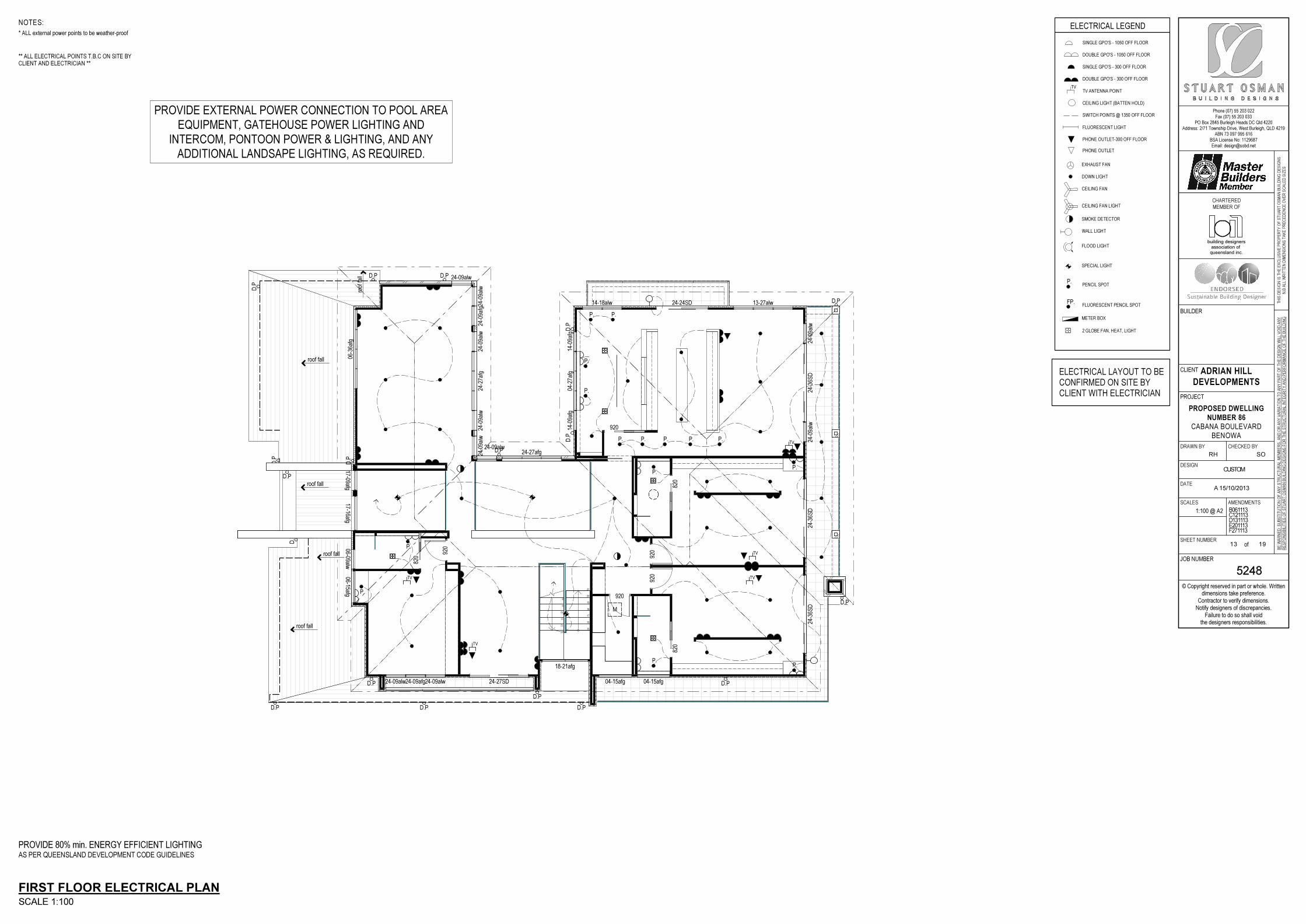
Phone (07) 55 203 022Fax (07) 55 203 033
PO Box 2845 Burleigh Heads DC Qld 4220Address: 2/71 Township Drive, West Burleigh, QLD 4219
ABN 73 097 995 616BSA License No: 1129687Email: [email protected]
© Copyright reserved in part or whole. Writtendimensions take preference.
Contractor to verify dimensions.Notify designers of discrepancies.
Failure to do so shall voidthe designers responsibilities.
TH
IS D
ES
IGN
IS
TH
E E
XC
LU
SIV
E P
RO
PE
RT
Y O
F S
TU
AR
T O
SM
AN
BU
ILD
ING
DE
SIG
NS
N.B
AL
L W
RIT
TE
N D
IME
NS
ION
S T
AK
E P
RE
CE
DE
NC
E O
VE
R S
CA
LE
D S
IZE
S
BE
WA
RN
ED
: S
UB
ST
ITU
TIO
N O
F A
NY
ST
RU
CT
UR
AL
ME
MB
ER
S,
AN
D O
R A
NY
VA
RIA
TIO
N T
O A
NY
PA
RT
OF
TH
E D
ES
IGN
WIL
L V
OID
AN
Y
RE
SP
ON
SIB
ILIT
IES
OF
ST
UA
RT
OS
MA
N B
UIL
DIN
G D
ES
IGN
S F
OR
TH
E S
TR
UC
TU
RA
L IN
TE
GR
ITY
AN
D P
ER
FO
RM
AN
CE
OF
TH
E B
UIL
DIN
G
CLIENT
PROJECT
JOB NUMBER
BUILDER
DRAWN BY CHECKED BY
DESIGN
DATE
SCALES AMENDMENTS
SHEET NUMBERof
CHARTERED
MEMBER OF
ADRIAN HILL
DEVELOPMENTS
PROPOSED DWELLING
NUMBER 86
CABANA BOULEVARDBENOWA
5248
RH
A 15/10/2013
B061113C121113D131113E201113F271113
SO
CUSTOM
1:100 @ A2
13 19
queensland inc.association of
building designers
920
820
820
920
920
920
920
820
04-2
7afg
14-0
9afg
14-0
9afg
14-18alw 13-27alw24-24SD
24-09alw24-09afg24-09alw 24-27SD
24-0
9alw
24-0
9alw
24-3
6SD
24-3
6SD
24-3
6SD
24-0
9alw
24-0
9afg
24-0
9alw
24-0
9alw
24-2
7afg
24-0
9alw
24-09alw
24-27afg24-09alw
18-21afg
04-15afg04-15afg
06-3
6afg
06-09alw06-15afg
8
9
10
11
12
13
15
16
17
18
19
20
21
D.P
D.P
D.P
D.P
D.P
D.P
D.P
D.P
D.P D.P D.P
D.P
17-09afg17-16afg
roof
fall
roof fall
roof fall
roof fall
P.
P.
P.
P. P.
P.
P.
P.
P.
P.
TV
TV
TV
TV
TV
P. P. P. P. P.
M
roof fall
D.P
D.P
D.P
D.P
D.P
D.P
FIRST FLOOR ELECTRICAL PLAN
SCALE 1:100
PROVIDE 80% min. ENERGY EFFICIENT LIGHTING
AS PER QUEENSLAND DEVELOPMENT CODE GUIDELINES
CLIENT WITH ELECTRICIAN
CONFIRMED ON SITE BY
ELECTRICAL LAYOUT TO BE
P.
ELECTRICAL LEGEND
TV
CEILING FAN LIGHT
PHONE OUTLET
2 GLOBE FAN, HEAT, LIGHT
METER BOX
SINGLE GPO'S - 1050 OFF FLOOR
SINGLE GPO'S - 300 OFF FLOOR
DOUBLE GPO'S - 300 OFF FLOOR
TV ANTENNA POINT
EXHAUST FAN
FLUORESCENT LIGHT
PHONE OUTLET-300 OFF FLOOR
CEILING FAN
DOWN LIGHT
WALL LIGHT
SMOKE DETECTOR
FLOOD LIGHT
PENCIL SPOT
SPECIAL LIGHT
SWITCH POINTS @ 1350 OFF FLOOR
DOUBLE GPO'S - 1050 OFF FLOOR
CEILING LIGHT (BATTEN HOLD)
NOTES:
* ALL external power points to be weather-proof
** ALL ELECTRICAL POINTS T.B.C ON SITE BYCLIENT AND ELECTRICIAN **
FP.FLUORESCENT PENCIL SPOT
PROVIDE EXTERNAL POWER CONNECTION TO POOL AREA
EQUIPMENT, GATEHOUSE POWER LIGHTING AND
INTERCOM, PONTOON POWER & LIGHTING, AND ANY
ADDITIONAL LANDSAPE LIGHTING, AS REQUIRED.
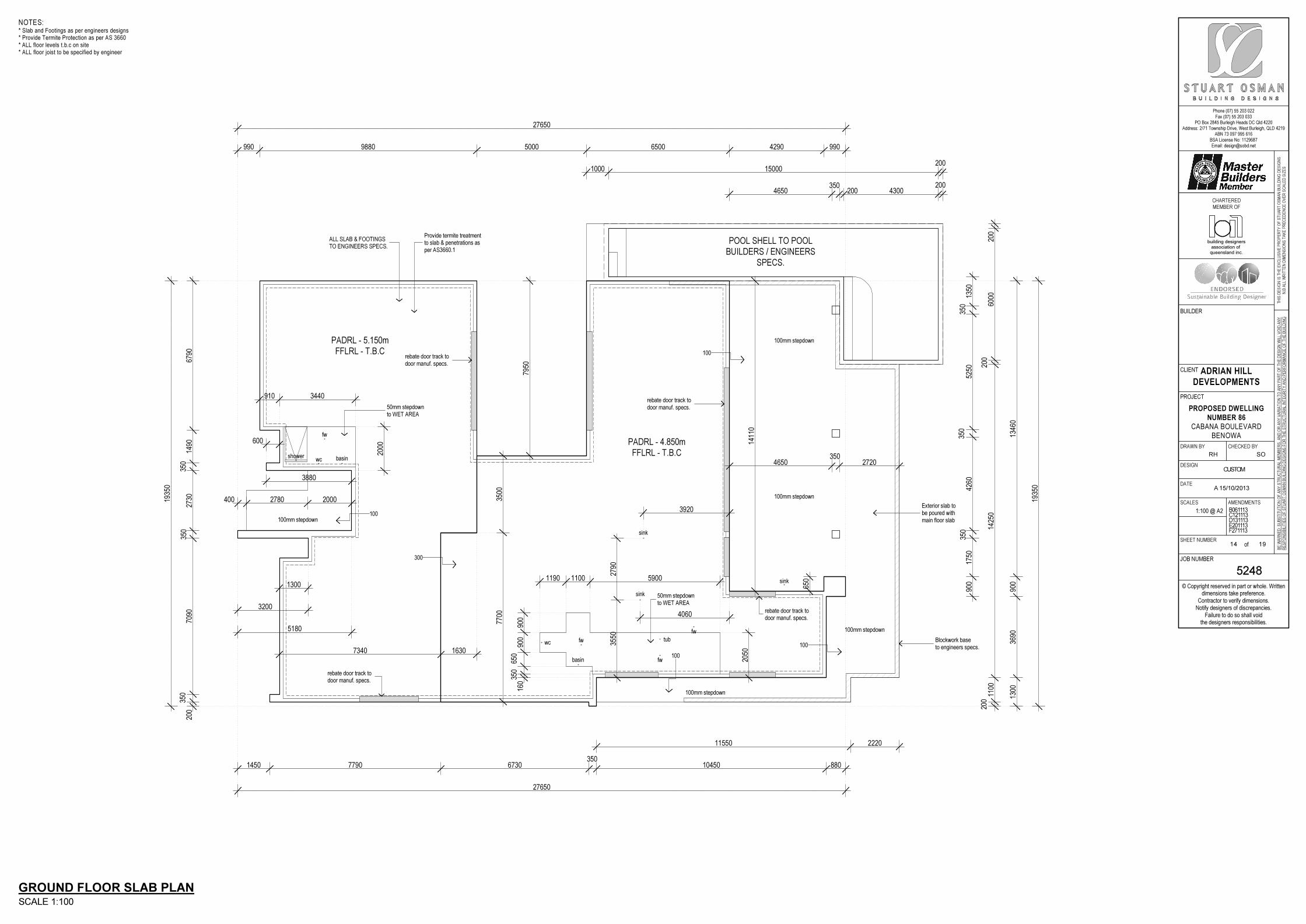
Phone (07) 55 203 022Fax (07) 55 203 033
PO Box 2845 Burleigh Heads DC Qld 4220Address: 2/71 Township Drive, West Burleigh, QLD 4219
ABN 73 097 995 616BSA License No: 1129687Email: [email protected]
© Copyright reserved in part or whole. Writtendimensions take preference.
Contractor to verify dimensions.Notify designers of discrepancies.
Failure to do so shall voidthe designers responsibilities.
TH
IS D
ES
IGN
IS
TH
E E
XC
LU
SIV
E P
RO
PE
RT
Y O
F S
TU
AR
T O
SM
AN
BU
ILD
ING
DE
SIG
NS
N.B
AL
L W
RIT
TE
N D
IME
NS
ION
S T
AK
E P
RE
CE
DE
NC
E O
VE
R S
CA
LE
D S
IZE
S
BE
WA
RN
ED
: S
UB
ST
ITU
TIO
N O
F A
NY
ST
RU
CT
UR
AL
ME
MB
ER
S,
AN
D O
R A
NY
VA
RIA
TIO
N T
O A
NY
PA
RT
OF
TH
E D
ES
IGN
WIL
L V
OID
AN
Y
RE
SP
ON
SIB
ILIT
IES
OF
ST
UA
RT
OS
MA
N B
UIL
DIN
G D
ES
IGN
S F
OR
TH
E S
TR
UC
TU
RA
L IN
TE
GR
ITY
AN
D P
ER
FO
RM
AN
CE
OF
TH
E B
UIL
DIN
G
CLIENT
PROJECT
JOB NUMBER
BUILDER
DRAWN BY CHECKED BY
DESIGN
DATE
SCALES AMENDMENTS
SHEET NUMBERof
CHARTERED
MEMBER OF
ADRIAN HILL
DEVELOPMENTS
PROPOSED DWELLING
NUMBER 86
CABANA BOULEVARDBENOWA
5248
RH
A 15/10/2013
B061113C121113D131113E201113F271113
SO
CUSTOM
1:100 @ A2
14 19
queensland inc.association of
building designers
27650
1450 7790 6730350
10450 880
11550 2220
1935
0
200
350
7090
350
2730
350
1490
6790
1300
3200
5180
400 2780 2000
3880
600
910 3440
2000
27650
990 9880 5000 6500 4290 990
1000 15000200
4650350
200 4300200
4650350
2720
7950
7700
3500
160
350
650
900
900
1190 1100 5900
406035
5027
90
2050
1300
3690
900
1346
0
1935
0
200
1100
1425
020
060
0020
0
900
1750
350
4260
350
5250
350
1350
7340 1630
3920
650
1411
0
50mm stepdownto WET AREA
50mm stepdownto WET AREA
rebate door track todoor manuf. specs.
rebate door track todoor manuf. specs.
rebate door track todoor manuf. specs.
rebate door track todoor manuf. specs.
ALL SLAB & FOOTINGSTO ENGINEERS SPECS.
Provide termite treatmentto slab & penetrations asper AS3660.1
Blockwork baseto engineers specs.
Exterior slab tobe poured withmain floor slab
fw
tub
sink
sink
sink
basin
basinwc
fw
fw
shower
wc
PADRL - 4.850m
FFLRL - T.B.C
PADRL - 5.150m
FFLRL - T.B.C
100mm stepdown
100mm stepdown
100mm stepdown
100mm stepdown
100mm stepdown
POOL SHELL TO POOL
BUILDERS / ENGINEERS
SPECS.
100
300
100
100
100
fw
GROUND FLOOR SLAB PLAN
SCALE 1:100
NOTES:* Slab and Footings as per engineers designs* Provide Termite Protection as per AS 3660* ALL floor levels t.b.c on site* ALL floor joist to be specified by engineer
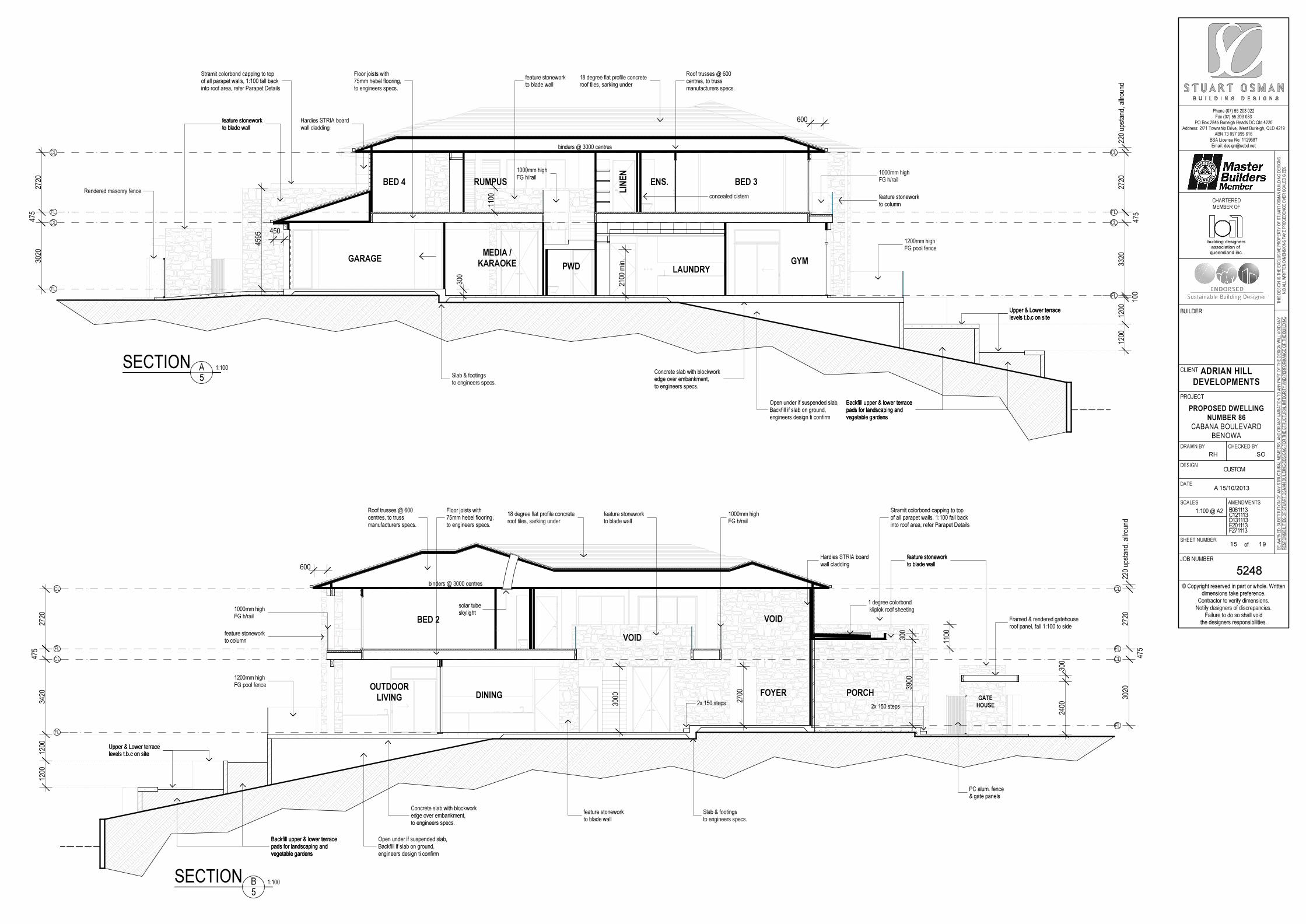
Phone (07) 55 203 022Fax (07) 55 203 033
PO Box 2845 Burleigh Heads DC Qld 4220Address: 2/71 Township Drive, West Burleigh, QLD 4219
ABN 73 097 995 616BSA License No: 1129687Email: [email protected]
© Copyright reserved in part or whole. Writtendimensions take preference.
Contractor to verify dimensions.Notify designers of discrepancies.
Failure to do so shall voidthe designers responsibilities.
TH
IS D
ES
IGN
IS
TH
E E
XC
LU
SIV
E P
RO
PE
RT
Y O
F S
TU
AR
T O
SM
AN
BU
ILD
ING
DE
SIG
NS
N.B
AL
L W
RIT
TE
N D
IME
NS
ION
S T
AK
E P
RE
CE
DE
NC
E O
VE
R S
CA
LE
D S
IZE
S
BE
WA
RN
ED
: S
UB
ST
ITU
TIO
N O
F A
NY
ST
RU
CT
UR
AL
ME
MB
ER
S,
AN
D O
R A
NY
VA
RIA
TIO
N T
O A
NY
PA
RT
OF
TH
E D
ES
IGN
WIL
L V
OID
AN
Y
RE
SP
ON
SIB
ILIT
IES
OF
ST
UA
RT
OS
MA
N B
UIL
DIN
G D
ES
IGN
S F
OR
TH
E S
TR
UC
TU
RA
L IN
TE
GR
ITY
AN
D P
ER
FO
RM
AN
CE
OF
TH
E B
UIL
DIN
G
CLIENT
PROJECT
JOB NUMBER
BUILDER
DRAWN BY CHECKED BY
DESIGN
DATE
SCALES AMENDMENTS
SHEET NUMBERof
CHARTERED
MEMBER OF
ADRIAN HILL
DEVELOPMENTS
PROPOSED DWELLING
NUMBER 86
CABANA BOULEVARDBENOWA
5248
RH
A 15/10/2013
B061113C121113D131113E201113F271113
SO
CUSTOM
1:100 @ A2
15 19
queensland inc.association of
building designers
1200
1200
100
3320
475
2720
220
upst
and,
allr
ound
3020
475
2720
300
2100
min
.
4595
600
450
1100
Stramit colorbond capping to topof all parapet walls, 1:100 fall backinto roof area, refer Parapet Details
18 degree flat profile concreteroof tiles, sarking under
Roof trusses @ 600centres, to trussmanufacturers specs.
feature stoneworkto blade wallfeature stoneworkto blade wall
1000mm highFG h/rail
Upper & Lower terracelevels t.b.c on siteUpper & Lower terracelevels t.b.c on site
Hardies STRIA boardwall cladding
Rendered masonry fencefeature stoneworkto column
1200mm highFG pool fence
Concrete slab with blockworkedge over embankment,to engineers specs.
Backfill upper & lower terracepads for landscaping andvegetable gardens
Backfill upper & lower terracepads for landscaping andvegetable gardens
Slab & footingsto engineers specs.
feature stoneworkto blade wall
Floor joists with75mm hebel flooring,to engineers specs.
1000mm highFG h/rail
concealed cistern
Open under if suspended slab,Backfill if slab on ground,engineers design ti confirm
SECTION 1:100
5
CL
FL
CL
FL
CL
FL
CL
FL
A
binders @ 3000 centres
GARAGE GYM
BED 3
LAUNDRYPWD
MEDIA /
KARAOKE
BED 4 RUMPUS
LINEN
ENS.
1200
1200
3420
475
2720
3020
475
2720
220
upst
and,
allr
ound
600
3900
300
1100
2700
3000
2400
300
1 degree colorbond kliplok roof sheeting
Stramit colorbond capping to topof all parapet walls, 1:100 fall backinto roof area, refer Parapet Details
Roof trusses @ 600centres, to trussmanufacturers specs.
feature stoneworkto blade wallfeature stoneworkto blade wall
1000mm highFG h/rail
Upper & Lower terracelevels t.b.c on site
Hardies STRIA boardwall cladding
Upper & Lower terracelevels t.b.c on site
feature stoneworkto column
1200mm highFG pool fence
Backfill upper & lower terracepads for landscaping andvegetable gardens
Backfill upper & lower terracepads for landscaping andvegetable gardens
feature stoneworkto blade wall
Floor joists with75mm hebel flooring,to engineers specs.
Framed & rendered gatehouseroof panel, fall 1:100 to side
feature stoneworkto blade wall
Slab & footingsto engineers specs.
2x 150 steps2x 150 steps
PC alum. fence& gate panels
18 degree flat profile concreteroof tiles, sarking under
solar tubeskylight
Concrete slab with blockworkedge over embankment,to engineers specs.
Open under if suspended slab,Backfill if slab on ground,engineers design ti confirm
1000mm highFG h/rail
CL
FL
CL
FL
CL
FL
CL
FL
binders @ 3000 centres
VOID
FOYER PORCHGATE
HOUSE
DININGOUTDOOR
LIVING
BED 2
VOID
B
5
1:100SECTION
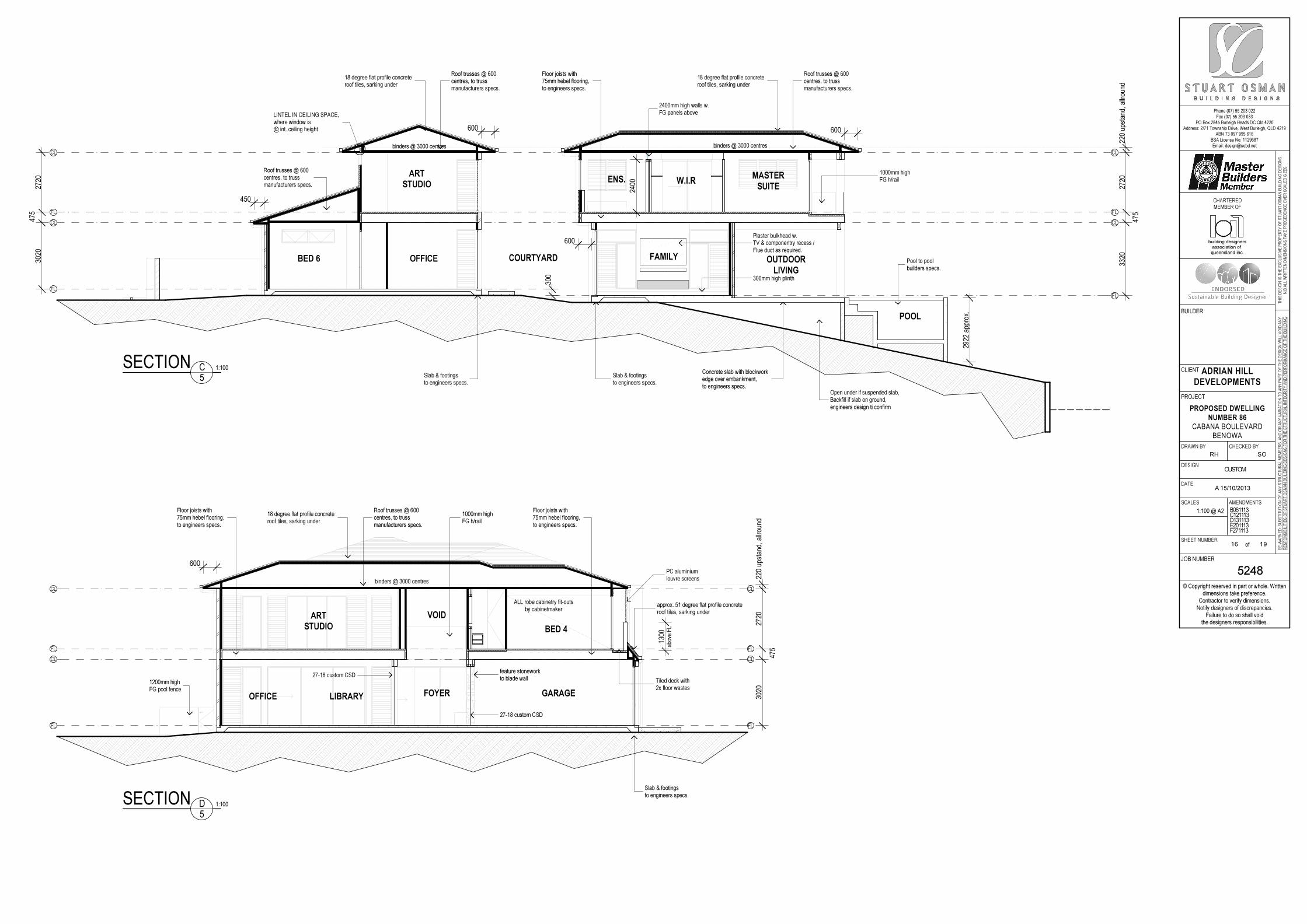
Phone (07) 55 203 022Fax (07) 55 203 033
PO Box 2845 Burleigh Heads DC Qld 4220Address: 2/71 Township Drive, West Burleigh, QLD 4219
ABN 73 097 995 616BSA License No: 1129687Email: [email protected]
© Copyright reserved in part or whole. Writtendimensions take preference.
Contractor to verify dimensions.Notify designers of discrepancies.
Failure to do so shall voidthe designers responsibilities.
TH
IS D
ES
IGN
IS
TH
E E
XC
LU
SIV
E P
RO
PE
RT
Y O
F S
TU
AR
T O
SM
AN
BU
ILD
ING
DE
SIG
NS
N.B
AL
L W
RIT
TE
N D
IME
NS
ION
S T
AK
E P
RE
CE
DE
NC
E O
VE
R S
CA
LE
D S
IZE
S
BE
WA
RN
ED
: S
UB
ST
ITU
TIO
N O
F A
NY
ST
RU
CT
UR
AL
ME
MB
ER
S,
AN
D O
R A
NY
VA
RIA
TIO
N T
O A
NY
PA
RT
OF
TH
E D
ES
IGN
WIL
L V
OID
AN
Y
RE
SP
ON
SIB
ILIT
IES
OF
ST
UA
RT
OS
MA
N B
UIL
DIN
G D
ES
IGN
S F
OR
TH
E S
TR
UC
TU
RA
L IN
TE
GR
ITY
AN
D P
ER
FO
RM
AN
CE
OF
TH
E B
UIL
DIN
G
CLIENT
PROJECT
JOB NUMBER
BUILDER
DRAWN BY CHECKED BY
DESIGN
DATE
SCALES AMENDMENTS
SHEET NUMBERof
CHARTERED
MEMBER OF
ADRIAN HILL
DEVELOPMENTS
PROPOSED DWELLING
NUMBER 86
CABANA BOULEVARDBENOWA
5248
RH
A 15/10/2013
B061113C121113D131113E201113F271113
SO
CUSTOM
1:100 @ A2
16 19
queensland inc.association of
building designers
3320
475
2720
220
upst
and,
allr
ound
3020
475
2720
2400
600
2922
app
rox.
300
600
450
600
18 degree flat profile concreteroof tiles, sarking under
Roof trusses @ 600centres, to trussmanufacturers specs.
Floor joists with75mm hebel flooring,to engineers specs.
18 degree flat profile concreteroof tiles, sarking under
Roof trusses @ 600centres, to trussmanufacturers specs.
Slab & footingsto engineers specs.
Slab & footingsto engineers specs.
Roof trusses @ 600centres, to trussmanufacturers specs.
LINTEL IN CEILING SPACE,where window is@ int. ceiling height
1000mm highFG h/rail
2400mm high walls w.FG panels above
300mm high plinth
Plaster bulkhead w.TV & componentry recess /Flue duct as required.
Pool to poolbuilders specs.
Concrete slab with blockworkedge over embankment,to engineers specs.
Open under if suspended slab,Backfill if slab on ground,engineers design ti confirm
SECTION 1:100
5
CL
FL
CL
FL
CL
FL
CL
FL
C
binders @ 3000 centresbinders @ 3000 centres
POOL
OUTDOOR
LIVING
FAMILYCOURTYARD
MASTER
SUITEW.I.RENS.
ART
STUDIO
OFFICEBED 6
3020
475
2720
220
upst
and,
allr
ound
1300
600
18 degree flat profile concreteroof tiles, sarking under
Roof trusses @ 600centres, to trussmanufacturers specs.
feature stoneworkto blade wall
Floor joists with75mm hebel flooring,to engineers specs.
Floor joists with75mm hebel flooring,to engineers specs.
approx. 51 degree flat profile concreteroof tiles, sarking under
27-18 custom CSD
27-18 custom CSD
Slab & footingsto engineers specs.
1200mm highFG pool fence
Tiled deck with2x floor wastes
PC aluminiumlouvre screens
1000mm highFG h/rail
SECTION 1:100
5
CL
FL
CL
FL
D
CL
FL
CL
FL
binders @ 3000 centres
ALL robe cabinetry fit-outsby cabinetmaker
GARAGE
ART
STUDIO
VOID
FOYEROFFICE LIBRARY
BED 4
abov
e F
L
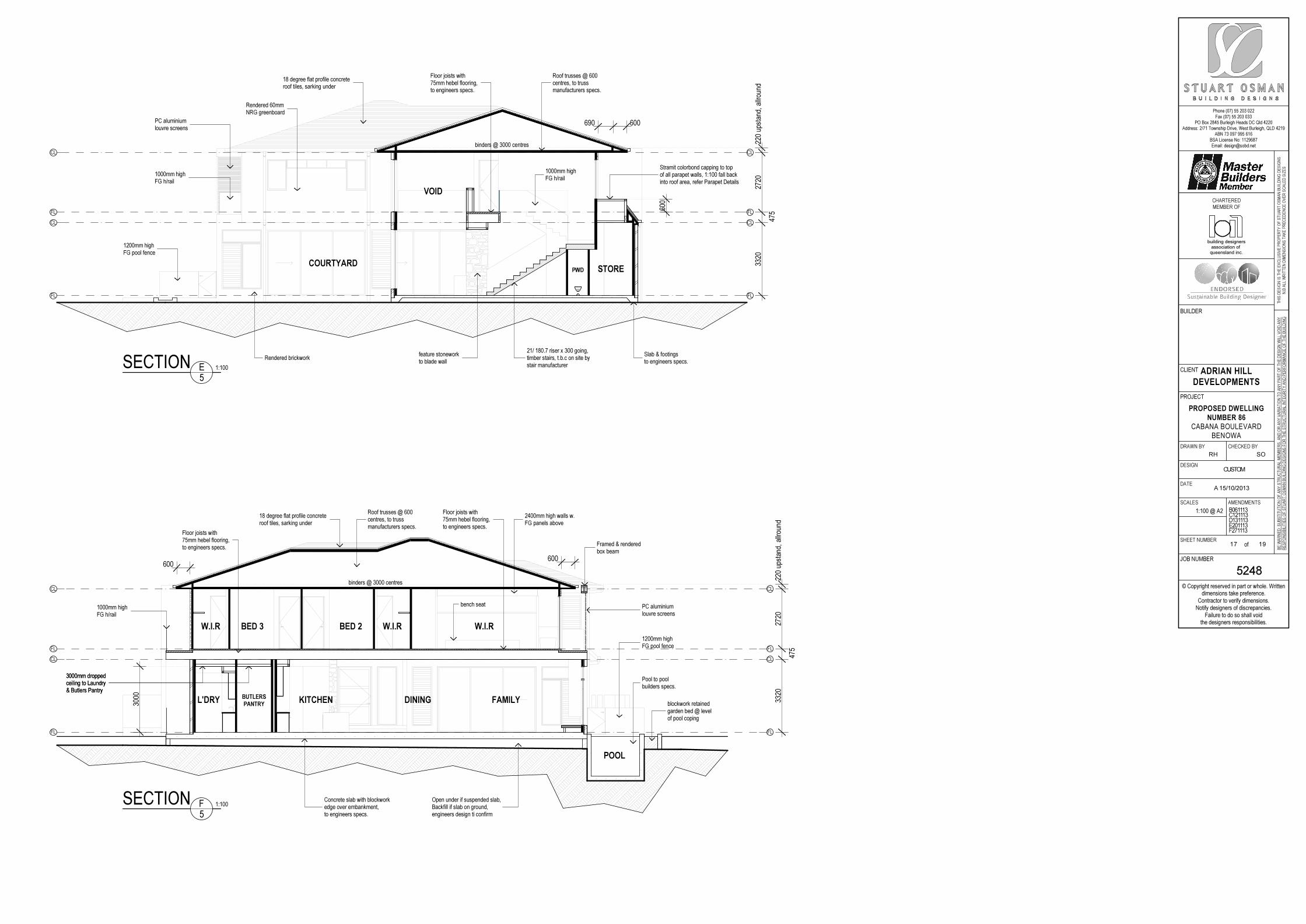
Phone (07) 55 203 022Fax (07) 55 203 033
PO Box 2845 Burleigh Heads DC Qld 4220Address: 2/71 Township Drive, West Burleigh, QLD 4219
ABN 73 097 995 616BSA License No: 1129687Email: [email protected]
© Copyright reserved in part or whole. Writtendimensions take preference.
Contractor to verify dimensions.Notify designers of discrepancies.
Failure to do so shall voidthe designers responsibilities.
TH
IS D
ES
IGN
IS
TH
E E
XC
LU
SIV
E P
RO
PE
RT
Y O
F S
TU
AR
T O
SM
AN
BU
ILD
ING
DE
SIG
NS
N.B
AL
L W
RIT
TE
N D
IME
NS
ION
S T
AK
E P
RE
CE
DE
NC
E O
VE
R S
CA
LE
D S
IZE
S
BE
WA
RN
ED
: S
UB
ST
ITU
TIO
N O
F A
NY
ST
RU
CT
UR
AL
ME
MB
ER
S,
AN
D O
R A
NY
VA
RIA
TIO
N T
O A
NY
PA
RT
OF
TH
E D
ES
IGN
WIL
L V
OID
AN
Y
RE
SP
ON
SIB
ILIT
IES
OF
ST
UA
RT
OS
MA
N B
UIL
DIN
G D
ES
IGN
S F
OR
TH
E S
TR
UC
TU
RA
L IN
TE
GR
ITY
AN
D P
ER
FO
RM
AN
CE
OF
TH
E B
UIL
DIN
G
CLIENT
PROJECT
JOB NUMBER
BUILDER
DRAWN BY CHECKED BY
DESIGN
DATE
SCALES AMENDMENTS
SHEET NUMBERof
CHARTERED
MEMBER OF
ADRIAN HILL
DEVELOPMENTS
PROPOSED DWELLING
NUMBER 86
CABANA BOULEVARDBENOWA
5248
RH
A 15/10/2013
B061113C121113D131113E201113F271113
SO
CUSTOM
1:100 @ A2
17 19
queensland inc.association of
building designers
3320
475
2720
220
upst
and,
allr
ound
690 600
600
18 degree flat profile concreteroof tiles, sarking under
Roof trusses @ 600centres, to trussmanufacturers specs.
Floor joists with75mm hebel flooring,to engineers specs.
1000mm highFG h/rail
1000mm highFG h/rail
1200mm highFG pool fence
PC aluminiumlouvre screens
Rendered 60mmNRG greenboard
Slab & footingsto engineers specs.
Stramit colorbond capping to topof all parapet walls, 1:100 fall backinto roof area, refer Parapet Details
feature stoneworkto blade wall
21/ 180.7 riser x 300 going,timber stairs, t.b.c on site bystair manufacturer
Rendered brickwork
CL
FL
CL
FL
CL
FL
CL
FL
SECTION 1:100
5
E
STOREPWD
VOID
COURTYARD
binders @ 3000 centres
3320
475
2720
220
upst
and,
allr
ound
600600
3000
Concrete slab with blockworkedge over embankment,to engineers specs.
Open under if suspended slab,Backfill if slab on ground,engineers design ti confirm
Pool to poolbuilders specs.
1200mm highFG pool fence
18 degree flat profile concreteroof tiles, sarking under
Roof trusses @ 600centres, to trussmanufacturers specs.
Floor joists with75mm hebel flooring,to engineers specs.
2400mm high walls w.FG panels above
Framed & renderedbox beam
PC aluminiumlouvre screens
1000mm highFG h/rail
bench seat
blockwork retainedgarden bed @ levelof pool coping
Floor joists with75mm hebel flooring,to engineers specs.
3000mm droppedceiling to Laundry& Butlers Pantry
3000mm droppedceiling to Laundry& Butlers Pantry
SECTION 1:100
5
F
POOL
binders @ 3000 centresCL
FL
CL
FL
CL
FL
CL
FL
W.I.R
L'DRYBUTLERS
PANTRYKITCHEN FAMILYDINING
W.I.RW.I.R BED 3 BED 2
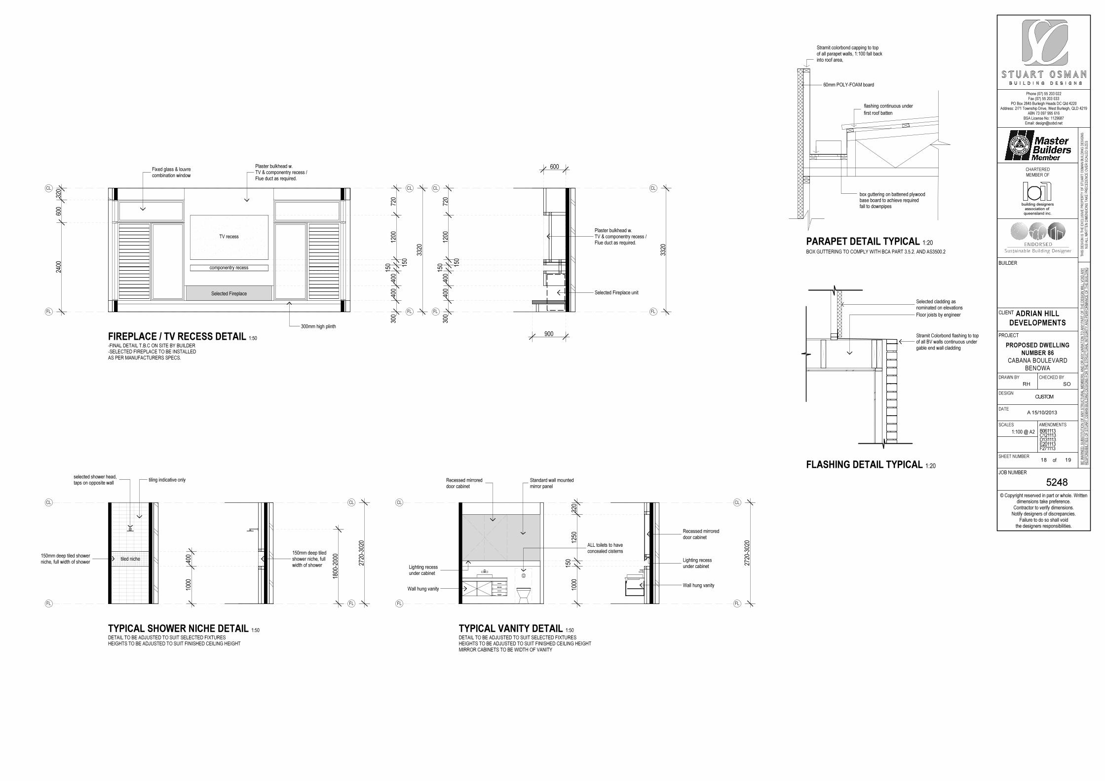
Phone (07) 55 203 022Fax (07) 55 203 033
PO Box 2845 Burleigh Heads DC Qld 4220Address: 2/71 Township Drive, West Burleigh, QLD 4219
ABN 73 097 995 616BSA License No: 1129687Email: [email protected]
© Copyright reserved in part or whole. Writtendimensions take preference.
Contractor to verify dimensions.Notify designers of discrepancies.
Failure to do so shall voidthe designers responsibilities.
TH
IS D
ES
IGN
IS
TH
E E
XC
LU
SIV
E P
RO
PE
RT
Y O
F S
TU
AR
T O
SM
AN
BU
ILD
ING
DE
SIG
NS
N.B
AL
L W
RIT
TE
N D
IME
NS
ION
S T
AK
E P
RE
CE
DE
NC
E O
VE
R S
CA
LE
D S
IZE
S
BE
WA
RN
ED
: S
UB
ST
ITU
TIO
N O
F A
NY
ST
RU
CT
UR
AL
ME
MB
ER
S,
AN
D O
R A
NY
VA
RIA
TIO
N T
O A
NY
PA
RT
OF
TH
E D
ES
IGN
WIL
L V
OID
AN
Y
RE
SP
ON
SIB
ILIT
IES
OF
ST
UA
RT
OS
MA
N B
UIL
DIN
G D
ES
IGN
S F
OR
TH
E S
TR
UC
TU
RA
L IN
TE
GR
ITY
AN
D P
ER
FO
RM
AN
CE
OF
TH
E B
UIL
DIN
G
CLIENT
PROJECT
JOB NUMBER
BUILDER
DRAWN BY CHECKED BY
DESIGN
DATE
SCALES AMENDMENTS
SHEET NUMBERof
CHARTERED
MEMBER OF
ADRIAN HILL
DEVELOPMENTS
PROPOSED DWELLING
NUMBER 86
CABANA BOULEVARDBENOWA
5248
RH
A 15/10/2013
B061113C121113D131113E201113F271113
SO
CUSTOM
1:100 @ A2
18 19
queensland inc.association of
building designers
3320
2400
600
320
300
400
400
150 15
0
1200
720
3320
300
400
400
150 15
0
1200
720
900
600
300mm high plinth
Plaster bulkhead w.TV & componentry recess /Flue duct as required.
Fixed glass & louvrecombination window
Plaster bulkhead w.TV & componentry recess /Flue duct as required.
Selected Fireplace unit
FL
CL
FL
CL
FL
CL
FL
CL
TV recess
componentry recess
FIREPLACE / TV RECESS DETAIL 1:50-FINAL DETAIL T.B.C ON SITE BY BUILDER-SELECTED FIREPLACE TO BE INSTALLEDAS PER MANUFACTURERS SPECS.
Selected Fireplace
1000
400
2720
-302
0
1800
-200
0
tiling indicative only
150mm deep tiled showerniche, full width of shower
selected shower head,taps on opposite wall
150mm deep tiledshower niche, fullwidth of shower
FL
CL
FL
CL
tiled niche
TYPICAL SHOWER NICHE DETAIL 1:50DETAIL TO BE ADJUSTED TO SUIT SELECTED FIXTURESHEIGHTS TO BE ADJUSTED TO SUIT FINISHED CEILING HEIGHT
2720
-302
0
1000
150
1250
320
Standard wall mountedmirror panel
Recessed mirroreddoor cabinet
Wall hung vanity
Lighting recessunder cabinet
Lighting recessunder cabinet
Wall hung vanity
Recessed mirroreddoor cabinet
ALL toilets to haveconcealed cisterns
FL
CL
FL
CL
TYPICAL VANITY DETAIL 1:50DETAIL TO BE ADJUSTED TO SUIT SELECTED FIXTURESHEIGHTS TO BE ADJUSTED TO SUIT FINISHED CEILING HEIGHTMIRROR CABINETS TO BE WIDTH OF VANITY
BOX GUTTERING TO COMPLY WITH BCA PART 3.5.2. AND AS3500.2
fall to downpipesbase board to achieve requiredbox guttering on battened plywood
PARAPET DETAIL TYPICAL 1:20
60mm POLY-FOAM board
flashing continuous under
first roof batten
FLASHING DETAIL TYPICAL 1:20
Stramit Colorbond flashing to topof all BV walls continuous undergable end wall cladding
Selected cladding asnominated on elevations
Floor joists by engineer
Stramit colorbond capping to topof all parapet walls, 1:100 fall backinto roof area,
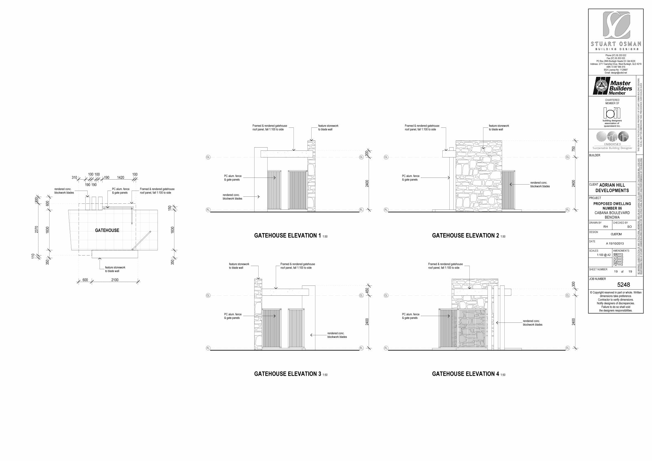
Phone (07) 55 203 022Fax (07) 55 203 033
PO Box 2845 Burleigh Heads DC Qld 4220Address: 2/71 Township Drive, West Burleigh, QLD 4219
ABN 73 097 995 616BSA License No: 1129687Email: [email protected]
© Copyright reserved in part or whole. Writtendimensions take preference.
Contractor to verify dimensions.Notify designers of discrepancies.
Failure to do so shall voidthe designers responsibilities.
TH
IS D
ES
IGN
IS
TH
E E
XC
LU
SIV
E P
RO
PE
RT
Y O
F S
TU
AR
T O
SM
AN
BU
ILD
ING
DE
SIG
NS
N.B
AL
L W
RIT
TE
N D
IME
NS
ION
S T
AK
E P
RE
CE
DE
NC
E O
VE
R S
CA
LE
D S
IZE
S
BE
WA
RN
ED
: S
UB
ST
ITU
TIO
N O
F A
NY
ST
RU
CT
UR
AL
ME
MB
ER
S,
AN
D O
R A
NY
VA
RIA
TIO
N T
O A
NY
PA
RT
OF
TH
E D
ES
IGN
WIL
L V
OID
AN
Y
RE
SP
ON
SIB
ILIT
IES
OF
ST
UA
RT
OS
MA
N B
UIL
DIN
G D
ES
IGN
S F
OR
TH
E S
TR
UC
TU
RA
L IN
TE
GR
ITY
AN
D P
ER
FO
RM
AN
CE
OF
TH
E B
UIL
DIN
G
CLIENT
PROJECT
JOB NUMBER
BUILDER
DRAWN BY CHECKED BY
DESIGN
DATE
SCALES AMENDMENTS
SHEET NUMBERof
CHARTERED
MEMBER OF
ADRIAN HILL
DEVELOPMENTS
PROPOSED DWELLING
NUMBER 86
CABANA BOULEVARDBENOWA
5248
RH
A 15/10/2013
B061113C121113D131113E201113F271113
SO
CUSTOM
1:100 @ A2
19 19
queensland inc.association of
building designers
310
190
100
190
100190 1420
100
600 2100
350
1830
600
350
1830
150
110
2370
300
rendered conc.blockwork blades
PC alum. fence& gate panels
feature stoneworkto blade wall
Framed & rendered gatehouseroof panel, fall 1:100 to side
GATEHOUSE
2400
300
Framed & rendered gatehouseroof panel, fall 1:100 to side
rendered conc.blockwork blades
PC alum. fence& gate panels
feature stoneworkto blade wall
FL
CL
FL
CL
GATEHOUSE ELEVATION 1 1:50
2400
750
Framed & rendered gatehouseroof panel, fall 1:100 to side
PC alum. fence& gate panels
rendered conc.blockwork blades
feature stoneworkto blade wall
FL
CL
FL
CL
GATEHOUSE ELEVATION 2 1:50
2400
450
rendered conc.blockwork blades
PC alum. fence& gate panels
Framed & rendered gatehouseroof panel, fall 1:100 to side
feature stoneworkto blade wall
FL
CL
FL
CL
GATEHOUSE ELEVATION 3 1:50
2400
300
Framed & rendered gatehouseroof panel, fall 1:100 to side
PC alum. fence& gate panels
rendered conc.blockwork blades
FL
CL
FL
CL
GATEHOUSE ELEVATION 4 1:50