Embed Size (px)
Citation preview

PROPOSED DALY UNIT NO. 10
Application for Enhanced Oil Recovery Waterflood Project
Bakken Formation
Bakken-Three Forks A Pool (01 62A)
Daly, Manitoba
April 24nd, 2015
Tundra Oil and Gas Partnership

2
TABLE OF CONTENTS
Section Page
Introduction 3 Summary 4 Reservoir Properties and Technical Discussion Geology 5 Stratigraphy 5 Sedimentology 5 Structure 6 Reservoir Continuity 6 Reservoir Quality 6 Fluid Contacts 7 Original Oil in Place Estimates 7 Historical Production 8
Unitization Unit Name 8 Unit Operator 9 Unitized Zone(s) 9 Unit Wells 9 Unit Lands 9 Tract Factors 9 Working Interest Owners 9 Waterflood EOR Development Technical Studies 10 Pre-Production of New Horizontal Wells 10 Reserve Recovery Profiles & Production Forecasts 10 Primary Production Forecast 10 Pre-Production Schedule / Timing for Conversion of Wells to Water Injection 11 Criteria for Conversion to Water Injection 11 Secondary Production Forecast 11 Estimated Fracture Gradient 11 Waterflood Operating Strategy Water Source 12 Injection Wells 12 Reservoir Pressure Management during Waterflood 13 Waterflood Surveillance and Optimization 13 On Going Reservoir Pressure Surveys 13 Economic Limits 13 Water Injection Facilities 14 Notifications 14

3
INTRODUCTION
The Daly portion of the Daly Sinclair Oilfield is located in Townships 8-11 Ranges 27-29 WPM (Figure 1).
Within the Daly oilfield, most Bakken reservoirs have been developed with vertical producing wells on
Primary Production and 40 acre spacing. Horizontal producing wells have recently been drilled by Tundra
Oil and Gas Partnership (Tundra) in the Daly field.
Within the area, potential exists for incremental production and reserves from a Waterflood EOR project
in the Three Forks and Middle Bakken oil reservoirs. The following represents an application by Tundra to
establish Daly Unit No. 10 (N ½ of Section 30-010-28W1 & all of section 31-10-28W1) and implement a
Secondary Waterflood EOR scheme within the Three Forks and Middle Bakken formations as outlined on
Figure 2.
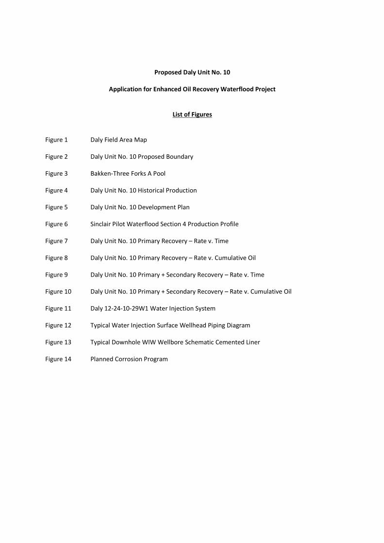
The proposed project area falls within the existing designated 01-62B Bakken-Three Forks Pool of the Daly
Sinclair Oilfield (Figure 3).

4
SUMMARY
1. The proposed Daly Unit No. 10 will include 6 producing horizontal wells, and two abandoned vertical
wells, within 24 Legal Sub Divisions (LSD) of the Middle Bakken/Three Forks producing reservoir. The
project is located west of Daly Unit No. 8 and east of the Kola Units 1 & 2 (Figure 2).
2. Total Net Original Oil in Place (OOIP) in Daly Unit No. 10 has been calculated to be 393.2 E3m3
(2473.2 Mbbl) for an average of 16.4 net E3m3 OOIP per 40 acre LSD. After petro physical analysis
OOIP values were determined using a permeability cutoff of 0.5 mD.
3. Cumulative production to the end of December 2014 from the 8 wells within the proposed Daly Unit
No. 10 project area was 47.9 E3m3 (301.3 Mbbl) of oil, and 156.6 E3m3 (985.0 Mbbl) of water,
representing a 12.2% Recovery Factor (RF) of the Net OOIP.
4. Estimated Ultimate Recovery (EUR) of producing oil reserves in the proposed Daly Unit No. 10 project
area has been calculated to be 54.1 E3m3 (340.2 Mbbl), with 6.2 E3m3 (39.0 Mbbl) remaining as of the
end of December 2014.
5. Ultimate oil recovery of the proposed Daly Unit No. 10 OOIP, under the current Primary Production
method, is forecasted to be 13.7%.
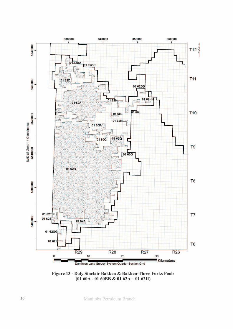
6. Figure 4 shows the production from the Daly Unit No. 10 which peaked in January 2012 at 61.8 m3 of
oil per day (OPD). As of December 2014, production was 8.5 m3 OPD, 49.8 m3 of water per day (WPD)
and an 85.4% watercut.
7. In Jan 2012, production averaged 12.4 m3 OPD per well in Daly Unit 10. As of December 2014, average
per well production has declined to 1.4 m3 OPD. Decline analysis of the group primary production
data forecasts total oil to continue declining at an annual rate of approximately 30.0% in the project
area.
8. The EUR of oil reserves under Secondary WF EOR for the proposed Daly Unit No. 10 has been
calculated to be 72.0 E3m3 (453.0 Mbbl), with 24.1 E3m3 (151.6 Mbbl) remaining. An incremental 17.9
E3m3 (112.6 Mbbl) in oil reserves, or 4.6%, are forecasted to be recovered under the proposed
Unitization and Secondary EOR production vs the existing Primary Production method.
9. Total RF under Secondary WF in the proposed Daly Unit No. 10 is estimated to be 18.3%.
10. Based on waterflood response in the adjacent main portion of the Sinclair field, the Three Forks and
Middle Bakken Formations in the proposed project area are believed to be suitable reservoirs for WF
EOR operations.
11. Existing cemented liner horizontal wells with multi-stage hydraulic fractures (Figure 13) will be
converted to injection wells within the proposed Daly Unit No. 10 setting up a 40 acre line drive
waterflood. Daly Unit No. 10 will be the first horizontal to horizontal line drive at 40 acre spacing in
the Daly portion of the Daly Sinclair Field.

5
RESERVOIR PROPERTIES AND TECHNICAL DISCUSSION
The proposed Daly Unit No. 10 project area is located within Township 10, Range 28 W1 of the Daly Sinclair
oil field. The proposed Daly Unit No. 10 currently consists of 6 producing horizontal wells and 2 abandoned
vertical wells within an area covering the N ½ of Section 30-010-28W1 and all of Section 31-010-28W1
(Figure 2). A project area well list complete with recent production statistics is attached as Table 3.
Tundra believes that the waterflood response in the adjacent Daly Sinclair field demonstrates potential
for incremental production and reserves from a WF EOR project in the subject Middle Bakken and/or
Three Forks oil reservoirs.
Geology
Stratigraphy:
The stratigraphy of the reservoir section for the proposed unit is shown on the structural cross section
attached as Appendix 1. The section runs NW to SE through the proposed unit. The producing sequence
in descending order consists of the Upper Bakken Shale, Middle Bakken Siltstone, Lyleton B Siltstone and
the Torquay silty shale. The reservoir units are represented by the Middle Bakken and Lyleton B Siltstones.
Sedimentology:
The Upper Bakken Shale is a black, organic rich, platy shale which forms the top seal for the underlying
Middle Bakken/Lyleton B reservoirs. The reservoir units in the proposed unit are analogous to the Bakken
/ Lyleton producing reservoirs that have been approved proximal to the proposed unit (Daly Unit 8, North
Ebor Unit 1 and Kola Unit 3) please see Appendix 2.
The Middle Bakken reservoir consists of fine to coarse grained grey siltstone to fine sandstone which may
be subdivided on the basis of lithologic characteristics into upper and lower units. The upper portion is
very often heavily bioturbated and is generally non-reservoir. These bioturbated beds often contain an
impoverished fauna consisting of well-worn brachiopod, coral and occasional crinoid fragments
suggesting deposition in a marginal marine environment. The lower part of the Middle Bakken is generally
finely laminated with alternating light and dark laminations with occasional bioturbation. Within the
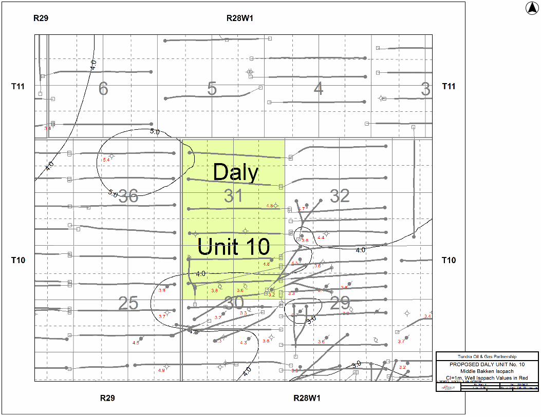
proposed unit, the Middle Bakken ranges from 5.0m to just over 4.0m in the Northwest (Appendix 3).
The Lyleton B (Three Forks) reservoir consists of buff to tan fine grained siltstone (occasionally very fine
siltstone) made up of quartz, feldspar and detrital dolomite with minor mica and clay mostly in the form
of clay clasts or chips. The upper Lyleton B is generally well bedded and shows evidence of parallel
lamination with occasional wind ripples. The coarser siltstones become interbedded with dark grey-green
(occasionally red) very fine grained siltstone in the lower portion of the Lyleton B and is generally non-
reservoir. The Lyleton B is approximately 1.0m to 2.0m thick within the proposed unit; erosionally
thinning from West and South (Appendix 4). The upper Lyleton B has been eroded away in the proposed
unit area.
The Torquay silty shale (Three Forks) forms the base of the reservoir sequence and is a brick red dolomitic
fine to very fine siltstone which is highly water soluble (Appendix 5). This is similar to the Red Shale Marker
found in the Western parts of Kola Units 1 & 2 to the West. This forms a good basal seal to the Middle
Bakken / Lyleton B reservoir sequence.

6
Structure:
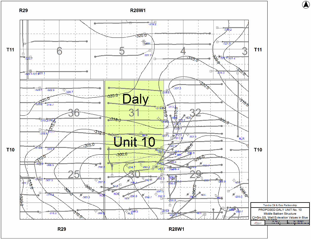
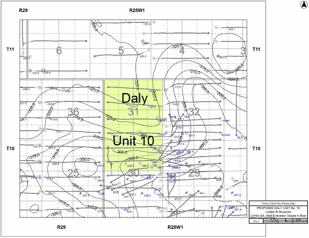
Structure contour maps are provided for the top of each major unit (Appendices 6 through 8). The
structure within the proposed unit area generally consists of an overall Westward dip. Structural
variations in the area are interpreted as being caused by dissolution of the underlying Prairie Evaporites.
Anomalous structural variations caused by dissolution are common in the Sinclair Daly area but do not
appear to represent continuous barriers to lateral fluid flow within the reservoir as they do not appear to
interrupt the lateral continuity of the reservoir beds (see cross section Appendix 1). None of these features
is found within the proposed unit area.
Reservoir Continuity:
Lateral continuity of the reservoir units is an essential requirement of a successful waterflood. As
demonstrated by the cross section (Appendix 1) and the isopach maps, the lateral continuity of the
reservoir within the proposed unit is very good.
Vertical reservoir continuity within the Middle Bakken and the underlying lower Lyleton B is likely limited
due to the heterolithic depositional environment and the multiple thin shale interbeds found in the lower
Lyleton B.
Reservoir Quality:
There are only 3 existing vertical wells (100/16-30-10-28W1, 100/04-31-10-28W1 and 100/09-31-10-
28W1) within the proposed unit area which reach the Middle Bakken formation. One core was taken in
the Bakken sequence in the proposed Unit No. 10. There are several wells (100/14-29-10-28W1, 100/13-
29-10-28W1 and 100/15-30-10-28W1 to name 3) with Bakken core analysis in close proximity to the
Southeast. There are limited wells with core data to the West, North and Northeast. The above noted
wells and others in the area of the proposed unit boundaries have been used to infer the Permeability
and Porosity for this unit application. The Middle Bakken reservoir is anticipated to have Fair to Good
reservoir throughout the proposed unit. Horizontal production further supports this expectation with 5
of the 5 wells producing over 4000m3.
Due to erosion of the upper portion of the Lyleton B formation there may be limited pay reservoir. This
will likely have limited contribution the overall recovery from this Unit leaving the MBKKN as the primary
reservoir. It should also be noted that there is limited core data in the immediate area, particularly in the
Lyleton B, and interpolative methods were used to generate the mapping and OOIP numbers for the area.
Further to this the 0.5mD cutoff reduces the limited data further as the lower Lyleton B tends to have
relatively low permeability values.
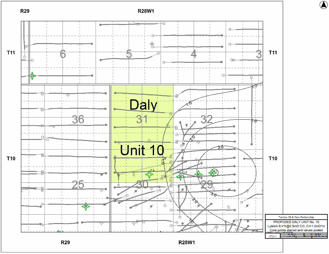
Permeability (k-h in mD*m) and porosity (Phi-h in por*m) maps for the two reservoir units are provided
(Appendices 9 through 12), point values on map posted at wells with core analysis). These maps are
created using core data and are generated as follows. First the core is divided into the reservoir units
present. This data is then subject to a permeability cutoff. Intervals that meet or exceed the cutoff are
multiplied by the interval thickness and then summed to get the total value for the Phi-h or k-h for that
particular reservoir unit. The value of the permeability cutoffs for each formation are the same values
used by GLJ for third party reserve evaluations on Tundra’s Sinclair properties. The permeability cutoffs
applied are as follows:

7
• Middle Bakken = 0.5 md
• Lyleton B = 0.5 md
As can be noted from the Phi-h and k-h maps the bulk of the reservoir in the proposed unit is contained
in the Middle Bakken formation. It is important to note that the 0.5 md cutoff effectively ignores pore
volume with permeability between 0.2 and 0.49 md that may contain moveable oil.
Fluid Contacts:
The oil/water contact for the Middle Bakken and Lyleton reservoir is estimated from production to be at
about -525 m subsea. In tight reservoirs such as these the transition zone could be considerable and the
top of the transition zone is estimated to be at about -490 m subsea based on production and simulation
studies of the reservoir. The postulated oil/water contact at -525 m subsea is below the lowest contour
on any of the attached structure contour maps.
OOIP Estimates
OOIP were calculated by Tundra Chief Geologist Barry Larson. Barry holds a BSc. in Geology from the U
of S, and has 35 years of industry experience, 19 of which are in the Williston Basin. The dataset used to
determine the OOIP values for the Unit was originally compiled by Barry Larson. It consists of conventional
core analysis of all available core in the Daly Sinclair area.
Total volumetric OOIP for the Middle Bakken and Lyleton B within the proposed unit has been calculated
to be 393.2 E3m3 (2473.2 MSTB) using Tundra internally created maps. Maps used were generated from
core data from 316 wells available in the Sinclair area (Appendix 13).
Net pay for each cored well is calculated using the formation specific permeability cut off discussed above.
Representative intervals that had a measured permeability greater than the formation specific cutoff were
considered pay. The weighted average porosity (phi) of all pay intervals for each formation was calculated
for each cored well. The height of pay (h) was derived by summing the heights of each representative
sample that met the permeability cut off. From these two parameters, a phi*h value was calculated for
all four productive horizons in all wells with core over each respective formation.
The phi*h values for all cored wells were contoured using Golden Software’s “Surfer 9” program using a
500 m grid node spacing. Phi*h values for each LSD were calculated off the associated Surfer 9 grid by
determining the values at the center of each LSD.
Tabulated parameters for each LSD from the calculations can be found in Table 4.
OOIP values were calculated using the following volumetric equation:
���� =���� ∗ ���� ∗ ������� ∗ �1 −����������������
���������������������������������
or

8
������3� =� ∗ ℎ ∗ ∅ ∗ �1 − �"�
#�∗10,000�2
ℎ�
or
�����'((�� =� ∗ ℎ ∗ ∅ ∗ �1 − �"�
#�∗ 3.28084
��
�∗ 7,758.367
((�
���� ∗ ��∗
1'((�
1,000((�
where
OOIP = Original Oil in Place by LSD (Mbbl, or m3)
A = Area (40acres, or 16.187 hectares, per LSD)
h * ∅ = Net Pay * Porosity, or Phi * h (ft, or m)
Bo = Formation Volume Factor of Oil (stb/rb, or sm3/rm3)
Sw = Water Saturation (decimal)
The initial oil formation volume factor was adopted from a PVT taken from the 3-3-8-29 Sinclair Bakken
well, thought to be representative of the fluid characteristics in the reservoir.
Historical Production
A historical group production history plot for the proposed Daly Unit No. 10 is shown as Figure 4. Oil
production commenced from the proposed Unit area in January 1988 and peaked during January 2012 at
61.8 m3 OPD. As of December 2014, production was 8.5 m3 of OPD, 49.8 m3 of WPD and an 85.4%
watercut.
Oil production is currently declining at an annual rate of approximately 30.0% under the current Primary
Production method.
The field’s production rate indicates the need for pressure restoration and maintenance, and
waterflooding is deemed to be the most efficient means of re-introducing energy back into the reservoir
system and to provide areal sweep between wells.
UNITIZATION
Unitization and implementation of a Waterflood EOR project is forecasted to increase overall recovery of
OOIP to 18.3%. The basis for unitization is to develop the lands in an effective manner that will be
conducive to waterflooding. Unitizing will enable the reservoir to have the greatest recovery possible by
allowing the development of additional drilling and injector conversions over time, in order to maintain
reservoir pressure and increase oil production.
Unit Name
Tundra proposes that the official name of the new Unit covering the N ½ of Section 30-010-28W1 and all
of section 31-010-28W1 shall be Daly Unit No. 10.

9
Unit Operator
Tundra will be the Operator of record for Daly Unit No.10.
Unitized Zone
The Unitized zone(s) to be waterflooded in the Daly Unit No. 10 will be the Middle Bakken and Three Forks
formations.
Unit Wells
The 6 horizontal wells and 2 vertical wells to be included in the proposed Daly Unit No. 10 are outlined in
Table 3.
Unit Lands
Daly Unit No. 10 will consist of 20 LSD as follows:
N ½ of Section 30 of Township 10, Range 28, W1M
All of Section 31 of Township 10, Range 28, W1M
The lands included in the 40 acre tracts are outlined in Table 1.
Tract Factors
The proposed Daly Unit No. 10 will consist of 24 Tracts based on the 40 acre LSD’s containing the existing
6 horizontal producing wells and 2 abandoned vertical wells.
The Tract Factor contribution for each of the LSD’s within the proposed Daly Unit No. 10 was calculated
as follows:
• Gross OOIP by LSD, minus cumulative production to date for the LSD as distributed by the LSD
specific Production Allocation (PA) % in the applicable producing horizontal or vertical well (to
yield Remaining Gross OOIP)
• Tract Factor by LSD = the product of Remaining Gross OOIP by LSD as a % of total proposed Unit
Remaining Gross OOIP
Tract Factor calculations for all individual LSD’s based on the above methodology are outlined in Table 2.
Working Interest Owners
Table 1 outlines the working interest (WI) for each recommended Tract within the proposed Daly Unit No.
10. Tundra holds a 100% WI ownership in all the proposed Tracts. Tundra will have a 100% WI in the
proposed Daly Unit No. 10.
10
WATERFLOOD EOR DEVELOPMENT
Technical Studies
The waterflood performance predictions for the proposed Daly Unit No. 10 are based on internal
engineering assessments. Internal reviews included analysis of available open-hole logs; core data; petro-
physics; seismic; drilling information; completion information; and production information. These
parameters were reviewed to develop a suite of geological maps and establish reservoir parameters to
support the calculation of the proposed Daly Unit No. 10 OOIP (Table 4).
Unitizing the proposed Daly Unit No. 10 will provide an extremely equitable means of maximizing ultimate
oil recovery in the project area. This is being done to better understand the most effective water flood
spacing for future development of the similar quality over a large portion of the Daly area.
Pre-Production of New Horizontal Injection Wells
Primary production from the horizontal producing wells in the proposed Daly Unit No. 10 has declined
significantly from peak rate indicating a need for secondary pressure support. It is likely two of the existing
producing horizontal wells will be converted to injection wells upon approval as shown in Figure 5, but
ultimately the final candidates for injection conversion will be chosen based on production performance
post unit approval. This will result in an effective 40 acre line drive waterflood pattern within Daly Unit
No. 10. Since the proposed horizontal injection wells have already been on production for a period of
time there not necessarily a need for an additional pre-production period within this unit, but again the
timing of conversion will be based on production performance post unit approval. It is tundra’s desire to
have the final injection conversion candidates on injection as soon as possible.
Tundra monitors reservoir pressure, fluid production and decline rates in each pattern to determine the
best time for each well to be converted to water injection.
Reserves Recovery Profiles and Production Forecasts
The waterflood performance predictions for the proposed Daly Unit No. 10 are based on oil production
decline curve analysis, and the secondary waterflood predictions are based on internal engineering
analysis performed by the Tundra reservoir engineering group.
Primary Production Forecast:
Cumulative production to the end December 2014 from the 8 wells within the proposed Daly Unit No. 10
project area was 47.9 E3m3 of oil, and 156.6 E3m3 of water, representing an 12.2% Recovery Factor (RF) of
the calculated Net OOIP.
Ultimate Primary Proved Producing oil reserves recovery for Daly Unit No. 10 has been estimated to be
54.1 E3m3, or a 13.7% RF of OOIP. Remaining Producing Primary Reserves has been estimated to be 6.2
E3m3 to the end of December 2014. The expected production decline and forecasted cumulative oil
recovery under continued Primary Production is shown in Figures 7 and 8.

11
Pre-Production Schedule / Timing for Conversion of Horizontal Wells to Water Injection:
Tundra will plan an injection conversion schedule to allow for the most expeditious development of the
waterflood within the proposed Daly Unit No. 10 while maximizing knowledge gained for further reservoir
characterization (Table 6).
Criteria for Conversion to Water Injection Well:
Two water injection wells are likely required for this proposed unit as shown in Figure 5.
Tundra will monitor the following parameters to assess the best timing for each individual horizontal well
to be converted from primary production to water injection service.
- Measured reservoir pressures at start of and/or through primary production
- Fluid production rates and any changes in decline rate
- Any observed production interference effects with adjacent vertical and horizontal wells
- Pattern mass balance and/or oil recovery factor estimates
- Reservoir pressure relative to bubble point pressure
The above schedule allows for the proposed Daly Unit No. 10 project to be developed equitably,
efficiently, and moves to project to the best condition for the start of waterflood as quickly as possible. It
also provides the Unit Operator flexibility to manage the reservoir conditions and response to help ensure
maximum ultimate recovery of OOIP.
Secondary EOR Production Forecast:
Daly Unit No. 10 will be the first horizontal line drive at 40 acre spacing in the Daly portion of the Daly
Sinclair Field. The proposed project oil production profile under secondary recovery has been developed
based on predictions derived from conventional internal engineering analysis performed by the Tundra
reservoir engineering group and therefore Tundra does not believe a 40 acres WF simulation is necessary
for the project area.
Secondary Waterflood plots of the expected oil production forecast over time and the expected oil
production v. cumulative oil are plotted in Figures 9 and 10, respectively. Total Secondary EUR for the
proposed Daly Unit No. 10 is estimated to be 72.0 E3m3 with 17.9 E3m3 remaining representing a total
recovery factor of 18.3% for the proposed Unit area. An incremental 17.9 E3m3 of oil, or an incremental
4.6% secondary recovery factor, are forecasted to be recovered under the proposed Unitization and water
flood scheme vs. the existing Primary Production method.
Estimated Fracture Gradient
Completion data from the existing producing wells within the project area indicate a fracture pressure
gradient range of 18.0 kPa/m true vertical depth (TVD). Tundra expects the fracture gradient encountered
during completion of the proposed horizontal injection well will be somewhat lower than these values
due to expected reservoir pressure depletion.

12
WATERFLOOD OPERATING STRATEGY
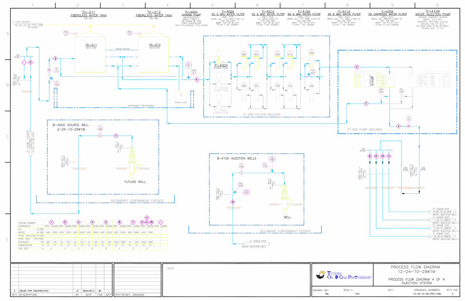
Water Source
Injection water for the proposed Daly Unit No. 10 will be supplied from the Jurassic source water well at
100/02-25-010-29W1 (2-25). Tundra received approval from the Petroleum Branch in March 2013 to use
the 2-25 well as a source water well for waterflood operations. Jurassic-sourced water will be pumped
from the 2-25 source well to the Daly 12-24-10-29 battery, where it will be filtered and then distributed
to the injection system. A diagram of the Daly 12-24 water injection system and new pipeline connection
to the project area injection wells is shown as Figure 11.
Produced water is not currently used for any water injection in the Tundra operated Daly Units and there
are no current plans to use produced water as a source supply for Daly Unit No. 10. Tundra does not
foresee any compatibility issues between the produced and injection waters based on previous
compatibility testing performed by a third party, Nalco Champion.
Injection Wells
The water injection wells for the proposed Daly unit No. 10 have been drilled, are currently producing and
plans are in progress to re-configure the wells for downhole injection after approval for waterflood has
been received (Figure 12). The horizontal injection wells will have been stimulated by multiple hydraulic
fracture treatments in a Hybrid Monobore completion design (Figure 13). Tundra has extensive
experience with horizontal fracturing in the area, and all jobs are rigorously programmed and monitored
during execution. This helps ensure optimum placement of each fracture stage to prevent, or minimize,
the potential for out-of-zone fracture growth and thereby limit the potential for future out-of-zone
injection.
The water injection wells will be placed on injection after the approval to inject has been received from
the Petroleum Branch. Wellhead injection pressures will be maintained below the least value of either:
1. The area specific known and calculated fracture gradient, or
2. The licensed surface injection Maximum Operating Pressure (MOP)
Tundra has a thorough understanding of area fracture gradients. A management program will be utilized
to set and routinely review injection target rates and pressures vs. surface MOP and the known area
formation fracture pressures.
All new water injection wells will be surface equipped with injection volume metering and rate/pressure
programmable logic control (PLC). An operating procedure for monitoring water injection volumes and
meter balancing will also be utilized to monitor the entire system measurement and integrity on a daily
basis.
The proposed Daly Unit No. 10 horizontal water injection well rate is forecasted to average 10 – 40 m3
WPD, based on expected reservoir permeability and pressure.

13
Reservoir Pressure Management during Waterflood
No recent or representative initial pressure surveys are currently available for the vertical producing wells
within the proposed Daly Unit No. 10 project area in the Bakken formation. The extremely long shut-in
and build-up times required to obtain any possible representative surveys from the producing wells are
economically prohibitive. Tundra will make all attempts to capture a reservoir pressure survey in the
proposed horizontal injection wells during the completion of the wells and prior to injection or production.
Tundra expects it will take 2-4 years to re-pressurize the reservoir due to cumulative primary production
voidage and pressure depletion. Initial monthly Voidage Replacement Ratio (VRR) is expected to be
approximately 1.2 to 2.0 within the unit during the fill up period. As the cumulative VRR approaches 1.0,
target reservoir operating pressure for waterflood operations will be 75-90% of original reservoir
pressure.
Waterflood Surveillance and Optimization
Daly Unit No. 10 EOR response and waterflood surveillance will consist of the following:
- Regular production well rate and WCT testing
- Daily water injection rate and pressure monitoring vs target
- Water injection rate/pressure/time vs. cumulative injection plot
- Reservoir pressure surveys as required to establish pressure trends
- Pattern VRR
- Potential use of chemical tracers to track water injector/producer responses
- Use of some or all of: Water Oil Ratio (WOR) trends, Log WOR vs Cum Oil, Hydrocarbon Pore
Volumes Injected, Conformance Plots
The above surveillance methods will provide an ever increasing understanding of reservoir performance,
and provide data to continually control and optimize the Daly Unit No. 10 waterflood operation.
Controlling the waterflood operation will significantly reduce or eliminate the potential for out-of-zone
injection, undesired channeling or water breakthrough, or out-of-Unit migration. The monitoring and
surveillance will also provide early indicators of any such issues so that waterflood operations may be
altered to maximize ultimate secondary reserves recovery from the proposed Daly Unit No. 10.
On Going Reservoir Pressure Surveys
For each cemented liner horizontal injection well, a measured reservoir pressure will be obtained prior to
water injection. These pressures will be reported within the Annual Progress Reports for Daly Unit No. 10
as per Section 73 of the Drilling and Production Regulation.
Economic Limits
Under the current Primary recovery method, existing wells within the proposed Daly Unit No. 10 will be
deemed uneconomic when the net oil rate and net oil price revenue stream becomes less than the current
producing operating costs. With any positive oil production response under the proposed Secondary
recovery method, the economic limit will be significantly pushed out into the future. The actual economic

14
cutoff point will then again be a function of net oil price, the magnitude and duration of production rate
response to the waterflood, and then current operating costs. Waterflood projects generally become
uneconomic to operate when Water Oil Ratios (WOR’s) exceed 100.
WATER INJECTION FACILITIES
The Daly Unit No. 10 waterflood operation will utilize the Tundra operated well 100/02-25-10-29W1,
sourced from the Jurassic, and water plant (WP) facilities located at the Daly 12-24-10-29W1 battery
(Figure 11).
A complete description of all planned system design and operational practices to prevent corrosion
related failures is shown in Appendix 14. All surface facilities and wellheads will have cathodic protection
to prevent corrosion. All injection flowlines will be made of fiberglass so corrosion will not be an issue.
Injectors will have a packer set above the Middle Bakken and Three Forks formations, and the annulus
between the tubing and casing will be filled with inhibited fluid.
NOTIFICATION OF MINERAL AND SURFACE RIGHTS OWNERS
Tundra is in the process of notifying all mineral rights and surface rights owners of this proposed EOR
project and formation of Daly Unit No. 10. Copies of the notices and proof of service, to all surface and
mineral rights owners will be forwarded to the Petroleum Branch when available to complete the Daly
Unit No. 10 Application.
Daly Unit No. 10 Unitization, and execution of the formal Daly Unit No. 10 Agreement by affected Mineral
Owners, is expected during Q4 2015. Copies of same will be forwarded to the Petroleum Branch, when
available, to complete the Daly Unit No. 10 Application.
Should the Petroleum Branch have further questions or require more information, please contact Cary
Reid at (403) 536-0787 or by email at [email protected]
TUNDRA OIL & GAS PARTNERSHIP
Original Signed by Cary Reid, P.L. (Eng.)
Proposed Daly Unit No. 10
Application for Enhanced Oil Recovery Waterflood Project
List of Figures
Figure 1 Daly Field Area Map
Figure 2 Daly Unit No. 10 Proposed Boundary
Figure 3 Bakken-Three Forks A Pool
Figure 4 Daly Unit No. 10 Historical Production
Figure 5 Daly Unit No. 10 Development Plan
Figure 6 Sinclair Pilot Waterflood Section 4 Production Profile
Figure 7 Daly Unit No. 10 Primary Recovery – Rate v. Time
Figure 8 Daly Unit No. 10 Primary Recovery – Rate v. Cumulative Oil
Figure 9 Daly Unit No. 10 Primary + Secondary Recovery – Rate v. Time
Figure 10 Daly Unit No. 10 Primary + Secondary Recovery – Rate v. Cumulative Oil
Figure 11 Daly 12-24-10-29W1 Water Injection System
Figure 12 Typical Water Injection Surface Wellhead Piping Diagram
Figure 13 Typical Downhole WIW Wellbore Schematic Cemented Liner
Figure 14 Planned Corrosion Program

Daly Field Boundary
Source: Manitoba Petroleum Branch Designated Fields and Pools – 2009
Figure 1

Manitoba Petroleum Branch30
Figure 13 - Daly Sinclair Bakken & Bakken-Three Forks Pools
(01 60A - 01 60BB & 01 62A � 01 62II)

daly unit no. 10.lwell BAKKEN 1987-07 to 2014-12
8 DALY (1) 47904.9 m3
Oil 62A 0.0 E3m3
Abandoned; Producing 156606.0 m3
© IHS, 1991 - 2015 Created in AccuMap Datum: NAD27TM
Printed on 4/22/2015 2:24:08 PMPage 1/1


sinclair unit no. 1 section 4 well list.wls BAKKEN; TORQUAY 2004-12 to 2014-11
16 DALY (1) 962915.4 bbl
Water Injection; Oil 62B 0.0 mcf
Injection; Producing 162B01 156271.5 bbl
© IHS, 1991 - 2015 Created in AccuMap Datum: NAD27TM
Printed on 2/19/2015 10:54:12 AMPage 1/1


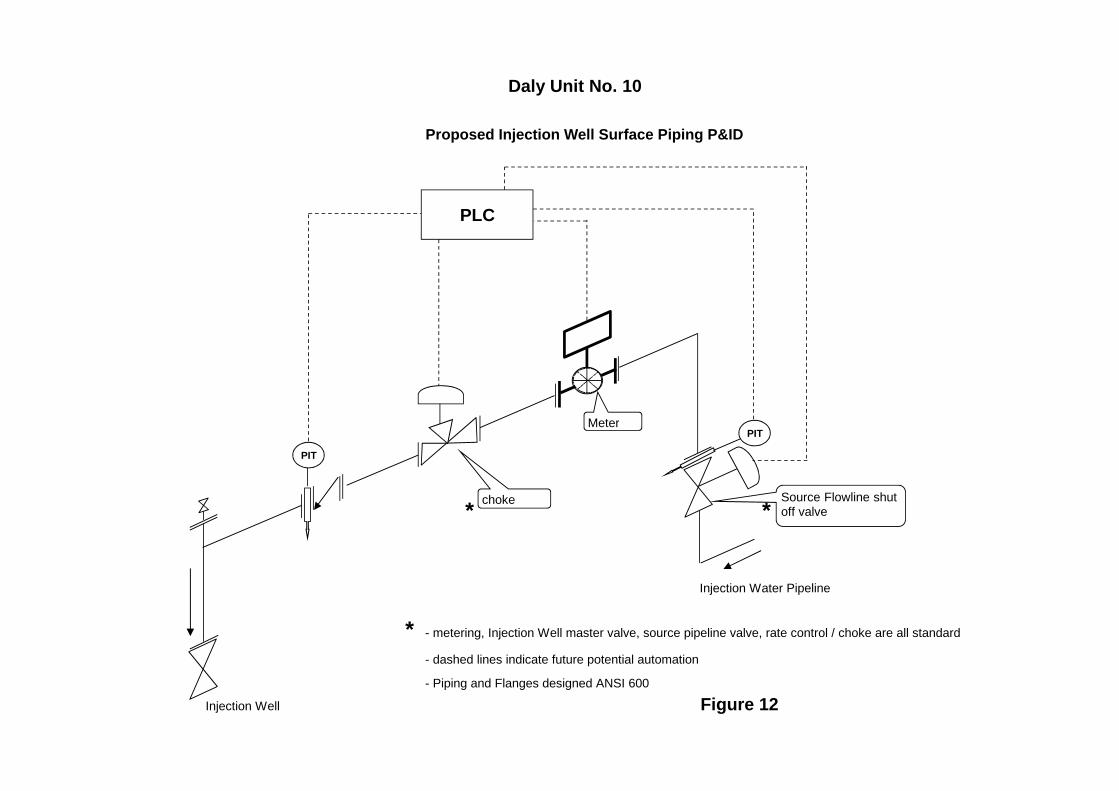
Daly Unit No. 10
Proposed Injection Well Surface Piping P&ID
* *
Injection Water Pipeline
* - metering, Injection Well master valve, source pipeline valve, rate control / choke are all standard
- dashed lines indicate future potential automation
- Piping and Flanges designed ANSI 600
Injection Well Figure 12
PIT
PIT
PLC
Source Flowline shut off valve
choke
Meter
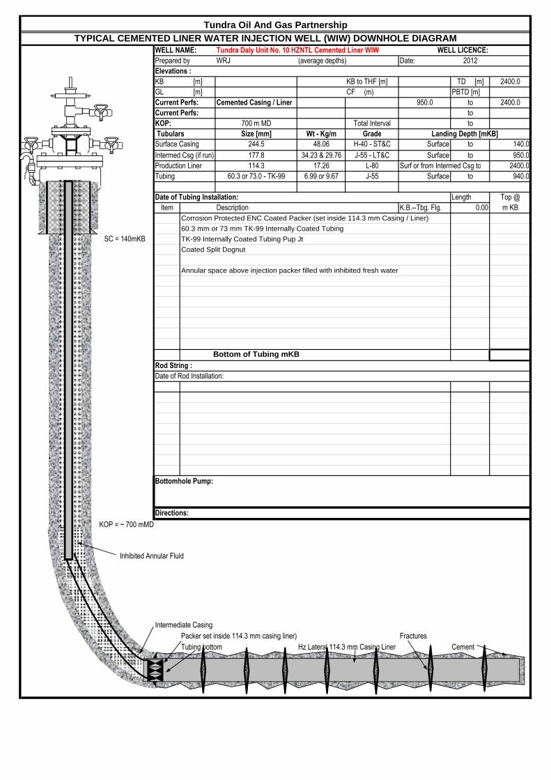
TYPICAL CEMENTED LINER WATER INJECTION WELL (WIW) DOWNHOLE DIAGRAMWELL NAME: Tundra Daly Unit No. 10 HZNTL Cemented Liner WIW WELL LICENCE:
Prepared by WRJ (average depths) Date: 2012
Elevations :
KB [m] KB to THF [m] TD [m] 2400.0
GL [m] CF (m) PBTD [m]
Current Perfs: Cemented Casing / Liner 950.0 to 2400.0
Current Perfs: to
KOP: 700 m MD Total Interval to
Tubulars Size [mm] Wt - Kg/m Grade Landing Depth [mKB]
Surface Casing 244.5 48.06 H-40 - ST&C Surface to 140.0
Intermed Csg (if run) 177.8 34.23 & 29.76 J-55 - LT&C Surface to 950.0
Production Liner 114.3 17.26 L-80 Surf or from Intermed Csg to 2400.0
Tubing 60.3 or 73.0 - TK-99 6.99 or 9.67 J-55 Surface to 940.0
Date of Tubing Installation: Length Top @
Item Description K.B.--Tbg. Flg. 0.00 m KB
Corrosion Protected ENC Coated Packer (set inside 114.3 mm Casing / Liner)
60.3 mm or 73 mm TK-99 Internally Coated Tubing
SC = 140mKB TK-99 Internally Coated Tubing Pup Jt
Coated Split Dognut
Annular space above injection packer filled with inhibited fresh water
Bottom of Tubing mKBRod String :
Date of Rod Installation:
Bottomhole Pump:
Directions:
KOP = ~ 700 mMD
Inhibited Annular Fluid
Intermediate Casing
Packer set inside 114.3 mm casing liner) Fractures
Tubing bottom Hz Lateral 114.3 mm Casing Liner Cement
Tundra Oil And Gas Partnership
0
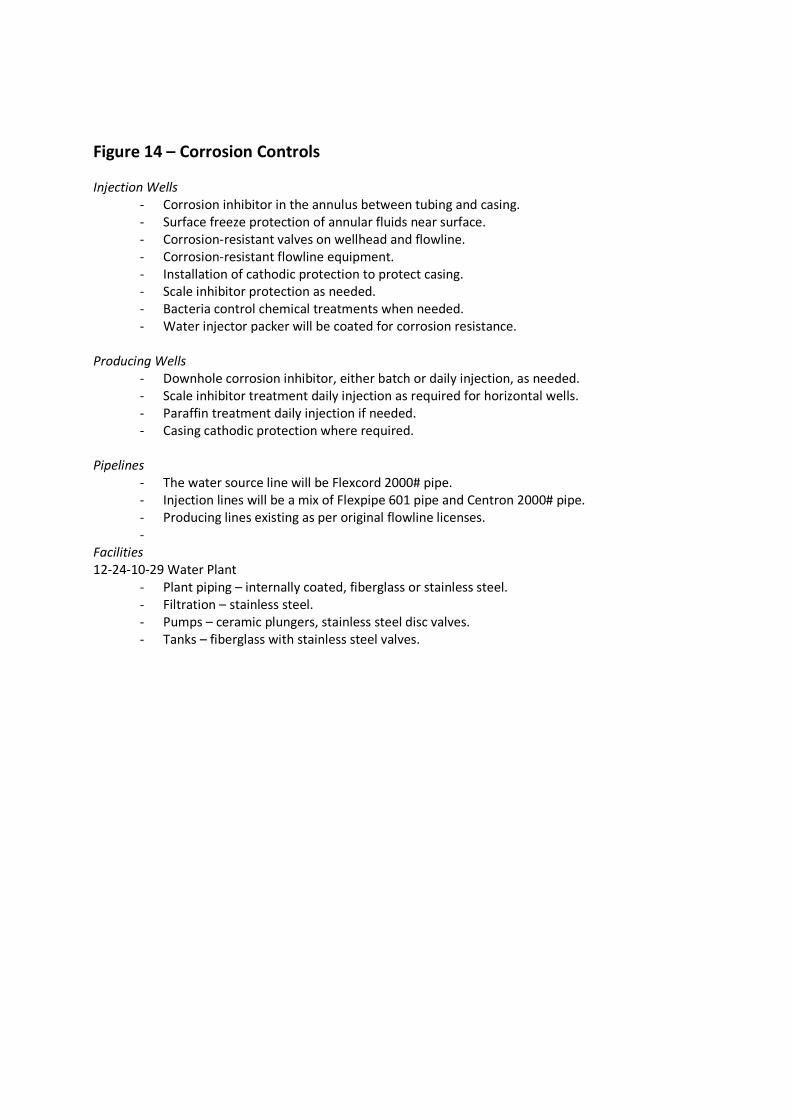
Figure 14 – Corrosion Controls
Injection Wells
- Corrosion inhibitor in the annulus between tubing and casing.
- Surface freeze protection of annular fluids near surface.
- Corrosion-resistant valves on wellhead and flowline.
- Corrosion-resistant flowline equipment.
- Installation of cathodic protection to protect casing.
- Scale inhibitor protection as needed.
- Bacteria control chemical treatments when needed.
- Water injector packer will be coated for corrosion resistance.
Producing Wells
- Downhole corrosion inhibitor, either batch or daily injection, as needed.
- Scale inhibitor treatment daily injection as required for horizontal wells.
- Paraffin treatment daily injection if needed.
- Casing cathodic protection where required.
Pipelines
- The water source line will be Flexcord 2000# pipe.
- Injection lines will be a mix of Flexpipe 601 pipe and Centron 2000# pipe.
- Producing lines existing as per original flowline licenses.
-
Facilities
12-24-10-29 Water Plant
- Plant piping – internally coated, fiberglass or stainless steel.
- Filtration – stainless steel.
- Pumps – ceramic plungers, stainless steel disc valves.
- Tanks – fiberglass with stainless steel valves.

Proposed Daly Unit No. 10
Application for Enhanced Oil Recovery Waterflood Project
List of Tables
Table 1 Tract Participation
Table 2 Tract Factor Calculation
Table 3 Current Well List and Status
Table 4 Original Oil in Place and Recovery Factors
Table 5 Reservoir and Fluid Properties
Table 6 Daly Unit No. 10 – Project Schedule

Tract No. Land Description Owner Share (%) Owner Share (%)
1 09-30-010-28W1M Tundra Oil & Gas Partnership 100%
Receiver General For Canada -
Frontier Lands Management
Division
100% 4.259065833%
2 10-30-010-28W1M Tundra Oil & Gas Partnership 100%
Receiver General For Canada -
Frontier Lands Management
Division
100% 3.075570750%
3 11-30-010-28W1M Tundra Oil & Gas Partnership 100% Minister of Finance 100% 3.499200516%
4 12-30-010-28W1M Tundra Oil & Gas Partnership 100% Minister of Finance 100% 4.406754101%
5 13-30-010-28W1M Tundra Oil & Gas Partnership 100% Minister of Finance 100% 4.364894102%
6 14-30-010-28W1M Tundra Oil & Gas Partnership 100% Minister of Finance 100% 3.482964545%
7 15-30-010-28W1M Tundra Oil & Gas Partnership 100%
Receiver General For Canada -
Frontier Lands Management
Division
100% 3.740735273%
8 16-30-010-28W1M Tundra Oil & Gas Partnership 100%
Receiver General For Canada -
Frontier Lands Management
Division
100% 4.443027173%
9 01-31-010-28W1M Tundra Oil & Gas Partnership 100% Bank of Nova Scotia 100% 3.914446015%
10 02-31-010-28W1M Tundra Oil & Gas Partnership 100% Bank of Nova Scotia 100% 3.645445355%
11 03-31-010-28W1M Tundra Oil & Gas Partnership 100% Bank of Nova Scotia 100% 3.420239087%
12 04-31-010-28W1M Tundra Oil & Gas Partnership 100% Bank of Nova Scotia 100% 3.332572002%
13 05-31-010-28W1M Tundra Oil & Gas Partnership 100% Bank of Nova Scotia 100% 4.336091836%
14 06-31-010-28W1M Tundra Oil & Gas Partnership 100% Bank of Nova Scotia 100% 4.313368428%
15 07-31-010-28W1M Tundra Oil & Gas Partnership 100% Bank of Nova Scotia 100% 4.352064113%
16 08-31-010-28W1M Tundra Oil & Gas Partnership 100% Bank of Nova Scotia 100% 4.540523109%
17 09-31-010-28W1M Tundra Oil & Gas Partnership 100% Bank of Nova Scotia 100% 4.586769075%
18 10-31-010-28W1M Tundra Oil & Gas Partnership 100% Bank of Nova Scotia 100% 4.233286705%
19 11-31-010-28W1M Tundra Oil & Gas Partnership 100% Bank of Nova Scotia 100% 4.251808715%
20 12-31-010-28W1M Tundra Oil & Gas Partnership 100% Bank of Nova Scotia 100% 4.344831705%
21 13-31-010-28W1M Tundra Oil & Gas Partnership 100% Bank of Nova Scotia 100% 4.975623366%
22 14-31-010-28W1M Tundra Oil & Gas Partnership 100% Bank of Nova Scotia 100% 4.881232944%
23 15-31-010-28W1M Tundra Oil & Gas Partnership 100% Bank of Nova Scotia 100% 4.806155637%
24 16-31-010-28W1M Tundra Oil & Gas Partnership 100% Bank of Nova Scotia 100% 4.793329616%
100.000000000%
TABLE NO. 1: TRACT PARTICIPATION FOR PROPOSED DALY UNIT NO. 10
Working Interest Royalty InterestTract
Participation

LS-SETract
OOIP
(m3)HZ Wells Alloc
Prod (m3)
Vert Wells
Cum Prodn
(m3)
Sum Hz + Vert
Alloc Cum ProdnOOIP - Cum Prodn Tract Factor Tract
09-30 09-30-010-28W1M 16,141 932.2 0.0 932.2 15,208 4.259065833% 09-30-010-28W1M10-30 10-30-010-28W1M 14,404 1,462.1 1,959.4 3,421.5 10,982 3.075570750% 10-30-010-28W1M11-30 11-30-010-28W1M 15,428 1,388.8 1,543.8 2,932.6 12,495 3.499200516% 11-30-010-28W1M12-30 12-30-010-28W1M 17,064 1,328.4 0.0 1,328.4 15,736 4.406754101% 12-30-010-28W1M13-30 13-30-010-28W1M 17,474 1,887.7 0.0 1,887.7 15,586 4.364894102% 13-30-010-28W1M14-30 14-30-010-28W1M 14,404 1,966.8 0.0 1,966.8 12,437 3.482964545% 14-30-010-28W1M15-30 15-30-010-28W1M 15,428 2,070.1 0.0 2,070.1 13,358 3.740735273% 15-30-010-28W1M16-30 16-30-010-28W1M 17,064 1,198.9 0.0 1,198.9 15,865 4.443027173% 16-30-010-28W1M01-31 01-31-010-28W1M 17,474 3,496.2 0.0 3,496.2 13,978 3.914446015% 01-31-010-28W1M02-31 02-31-010-28W1M 16,513 3,496.2 0.0 3,496.2 13,017 3.645445355% 02-31-010-28W1M03-31 03-31-010-28W1M 15,709 3,496.2 0.0 3,496.2 12,213 3.420239087% 03-31-010-28W1M04-31 04-31-010-28W1M 15,396 3,496.2 0.0 3,496.2 11,900 3.332572002% 04-31-010-28W1M05-31 05-31-010-28W1M 16,781 1,297.9 0.0 1,297.9 15,483 4.336091836% 05-31-010-28W1M06-31 06-31-010-28W1M 16,771 1,368.5 0.0 1,368.5 15,402 4.313368428% 06-31-010-28W1M07-31 07-31-010-28W1M 16,980 1,440.0 0.0 1,440.0 15,540 4.352064113% 07-31-010-28W1M08-31 08-31-010-28W1M 17,548 1,334.9 0.0 1,334.9 16,213 4.540523109% 08-31-010-28W1M09-31 09-31-010-28W1M 17,821 1,442.1 0.0 1,442.1 16,379 4.586769075% 09-31-010-28W1M10-31 10-31-010-28W1M 17,676 2,559.3 0.0 2,559.3 15,116 4.233286705% 10-31-010-28W1M11-31 11-31-010-28W1M 17,611 2,428.8 0.0 2,428.8 15,182 4.251808715% 11-31-010-28W1M12-31 12-31-010-28W1M 17,840 2,325.5 0.0 2,325.5 15,515 4.344831705% 12-31-010-28W1M13-31 13-31-010-28W1M 18,693 925.7 0.0 925.7 17,767 4.975623366% 13-31-010-28W1M14-31 14-31-010-28W1M 18,439 1,008.6 0.0 1,008.6 17,430 4.881232944% 14-31-010-28W1M15-31 15-31-010-28W1M 18,225 1,063.0 0.0 1,063.0 17,162 4.806155637% 15-31-010-28W1M16-31 16-31-010-28W1M 18,104 987.6 0.0 987.6 17,116 4.793329616% 16-31-010-28W1M
m3 393,203 357,083 100.000000000%
Mbbl 2,473
TABLE NO. 2: TRACT FACTOR CALCULATIONS FOR DALY UNIT NO. 10TRACT FACTORS BASED ON OIL-IN-PLACE (OOIP) MINUS CUMULATIVE PRODUCTION TO DECEMBER 2014

UWI
License
Number Type
Pool
Name
Producing
Zone Mode
On Prod
Date
Last
Prod Date
Cal Dly
Oil
(m3/d)
Monthly
Oil
(m3)
Cum Prd
Oil
(m3)
Cal Dly
Water
(m3/d)
Monthly
Water
(m3)
Cum Prd
Water
(m3)
WCT
(%)
100/10-30-010-28W1/2 003891 Vertical BAKKEN-THREE FORKS A BAKKEN Abandoned 6/1/1995 11/30/2010 0.0 0.4 1959.4 0.1 3.2 3320.9 88.89
100/11-30-010-28W1/0 003934 Vertical BAKKEN-THREE FORKS A BAKKEN Abandoned 7/1/1987 2/29/1996 0.5 13.3 1543.8 0.2 5.6 603.7 29.63
102/12-30-010-28W1/0 008588 Horizontal BAKKEN-THREE FORKS A BAKKEN Producing 3/1/2012 12/31/2014 2.1 65.6 5111.5 5.6 173.4 16699.1 72.55
102/13-30-010-28W1/0 007878 Horizontal BAKKEN-THREE FORKS A BAKKEN Producing 4/1/2011 12/31/2014 1.9 57.8 7123.5 5.6 173.6 36193.0 75.02
102/04-31-010-28W1/0 007141 Horizontal BAKKEN-THREE FORKS A BAKKEN Producing 1/1/2010 12/31/2014 1.0 30.3 13984.8 31.9 987.7 68044.0 97.02
100/05-31-010-28W1/0 007903 Horizontal BAKKEN-THREE FORKS A BAKKEN Producing 8/1/2011 12/31/2014 1.4 42.0 5441.3 1.9 57.6 9604.5 57.83
100/12-31-010-28W1/0 007549 Horizontal BAKKEN-THREE FORKS A BAKKEN Producing 11/1/2010 12/31/2014 1.0 31.3 8755.7 1.8 56.7 9714.7 64.43
100/13-31-010-28W1/0 007970 Horizontal BAKKEN-THREE FORKS A BAKKEN Producing 9/1/2011 12/31/2014 1.2 37.5 3984.9 3.0 94.5 12426.1 71.59
47,904.9 156,606.0
TABLE NO. 3: DALY UNIT NO. 10 WELL LIST
1 of 1

TABLE NO. 4: OOIP FOR DALY UNIT NO.10
Total OOIPUWI MBKKN Lyleton B GLJ cut offs (m3) MB Phi-h LB Phi-h SW MBKKN SW Lyleton UA SW Lyleton LA SW Lyleton B
0.5 md 0.5 md 0.5 md 0.5 md 0.5 md09-30-010-28W1M 16,141 0 16,141 0.18736 0.10605 0.45 0.45 0.45 0.4510-30-010-28W1M 14,645 0 14,645 0.16568 0.05317 0.45 0.45 0.45 0.4511-30-010-28W1M 12,764 0 12,764 0.15030 0.03016 0.45 0.45 0.45 0.4512-30-010-28W1M 11,643 0 11,643 0.13656 0.02565 0.45 0.45 0.45 0.4513-30-010-28W1M 13,533 0 13,533 0.15986 0.03095 0.45 0.45 0.45 0.4514-30-010-28W1M 14,404 0 14,404 0.16797 0.03651 0.45 0.45 0.45 0.4515-30-010-28W1M 15,428 0 15,428 0.18162 0.05860 0.45 0.45 0.45 0.4516-30-010-28W1M 17,064 0 17,064 0.19761 0.00000 0.45 0.45 0.45 0.4501-31-010-28W1M 17,474 0 17,474 0.20334 0.00000 0.45 0.45 0.45 0.4502-31-010-28W1M 16,513 0 16,513 0.19405 0.06116 0.45 0.45 0.45 0.4503-31-010-28W1M 15,709 0 15,709 0.18531 0.04544 0.45 0.45 0.45 0.4504-31-010-28W1M 15,396 0 15,396 0.17824 0.03634 0.45 0.45 0.45 0.4505-31-010-28W1M 16,781 0 16,781 0.19445 0.03896 0.45 0.45 0.45 0.4506-31-010-28W1M 16,771 0 16,771 0.19760 0.04610 0.45 0.45 0.45 0.4507-31-010-28W1M 16,980 0 16,980 0.20221 0.00000 0.45 0.45 0.45 0.4508-31-010-28W1M 17,548 0 17,548 0.20737 0.00000 0.45 0.45 0.45 0.4509-31-010-28W1M 17,821 0 17,821 0.21181 0.00000 0.45 0.45 0.45 0.4510-31-010-28W1M 17,676 0 17,676 0.21038 0.00000 0.45 0.45 0.45 0.4511-31-010-28W1M 17,611 0 17,611 0.20927 0.04473 0.45 0.45 0.45 0.4512-31-010-28W1M 17,840 0 17,840 0.20965 0.04004 0.45 0.45 0.45 0.4513-31-010-28W1M 18,693 0 18,693 0.22173 0.03994 0.45 0.45 0.45 0.4514-31-010-28W1M 18,439 0 18,439 0.21897 0.04261 0.45 0.45 0.45 0.4515-31-010-28W1M 18,225 0 18,225 0.21741 0.04544 0.45 0.45 0.45 0.4516-31-010-28W1M 18,104 0 18,104 0.21590 0.00000 0.45 0.45 0.45 0.45
393,203 m32,473 Mbbl
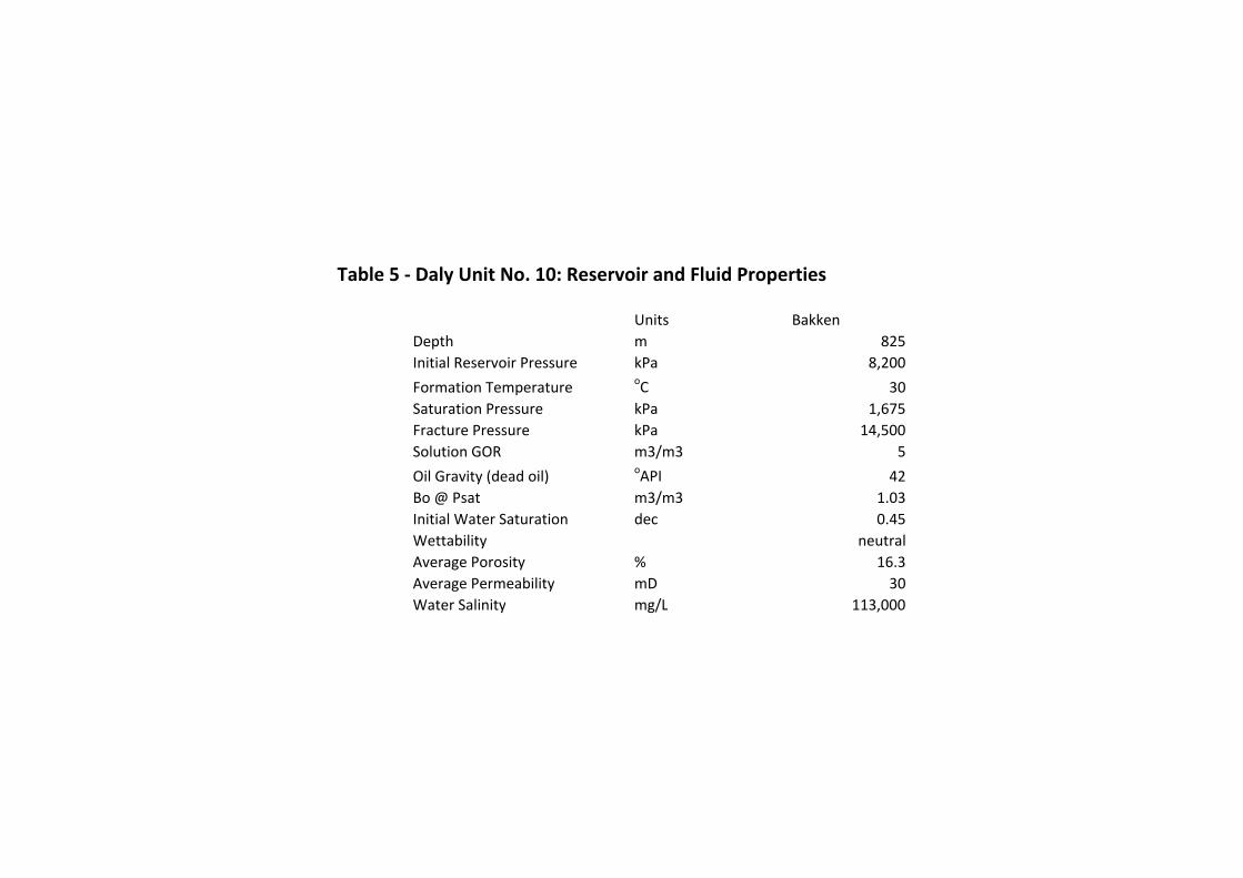
Table 5 - Daly Unit No. 10: Reservoir and Fluid Properties
Units Bakken
Depth m 825
Initial Reservoir Pressure kPa 8,200
Formation TemperatureoC 30
Saturation Pressure kPa 1,675
Fracture Pressure kPa 14,500
Solution GOR m3/m3 5
Oil Gravity (dead oil)oAPI 42
Bo @ Psat m3/m3 1.03
Initial Water Saturation dec 0.45
Wettability neutral
Average Porosity % 16.3
Average Permeability mD 30
Water Salinity mg/L 113,000
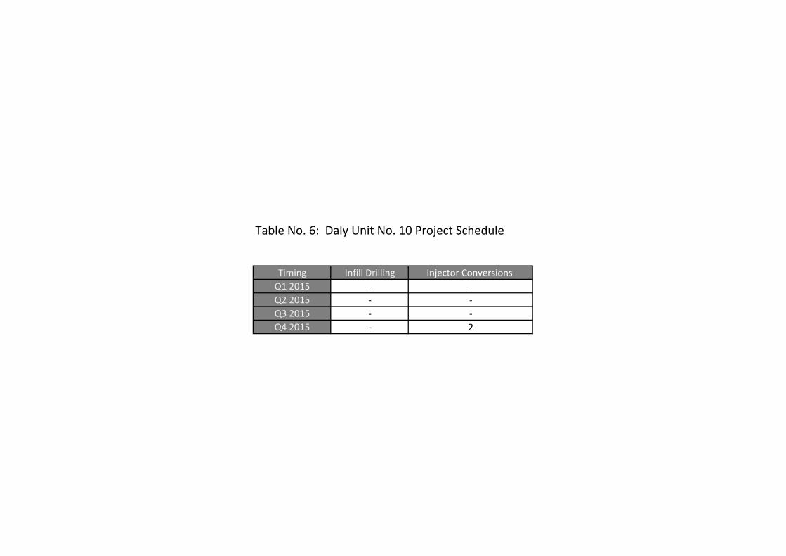
Table No. 6: Daly Unit No. 10 Project Schedule
Timing Infill Drilling Injector Conversions
Q1 2015 - -
Q2 2015 - -
Q3 2015 - -
Q4 2015 - 2

Proposed Daly Unit No. 10
Application for Enhanced Oil Recovery Waterflood Project
List of Appendices
Appendix 1 Structural Cross-Section
Appendix 2 Map of Offsetting Units
Appendix 3 Middle Bakken Isopach
Appendix 4 Lyleton B Isopach
Appendix 5 Torquay Isopach
Appendix 6
Appendix 7
Middle Bakken Structure
Lyleton B Structure
Appendix 8 Torquay Structure
Appendix 9
Appendix 10
Middle Bakken k*h @ 0.5 mD CO
Middle Bakken phi*h @ 0.5 mD CO
Appendix 11 Lyleton B k*h @ 0.5 mD CO
Appendix 12 Lyleton B phi*h @ 0.5 mD CO
Appendix 13 Area Cored Wells

UWID: 100/14-36-010-29W1/00 Well Name: NORTHROCK ET AL DALY PROV.
UWID: 100/08-31-010-28W1/00 Well Name: MOUNTCLIFF DALY
UWID: 100/16-30-010-28W1/00 Well Name: TUNDRA DALY ~~~~~~~~~~~~~~~~~~~~~~~~~~~~~~~~~~~~~~~~~~~~~~~~~~~~~~~~~~~~ PRODUCTION SUMMARY HIST: 1990/09 - 1991/10 FIELD: DALY SINCLAIR[01] ST: ABD Producer Mldgpl_U POOL: LODGEPOLE A[59A] ON: 1990/09/01 | GAS (e3m3) | OIL (m3) | WTR (m3) |Hrs | CUMULATIVE PROD: | | 28 | 1,062 | | F4Mo TOTAL PROD: | | 23 | 839 |1,872 | F4Mo DlyAvg PROD: | | 0.29 | 10.76 | | L4Mo TOTAL PROD: | | 4 | 3 | 24 | L4Mo DlyAvg PROD: | | 3.70 | 3.00 | | MR4Mo TOTAL PROD: | | | | | MR4Mo DlyAvg PROD: | | | | | F4Mo GOR: WC: 97.3% L4Mo GOR: WC: 44.8%
UWID: 100/14-29-010-28W1/00 Well Name: TUNDRA DALY PROV.
825
850
875
900
TD 903.0m
BRDBR
LYL_C
TORQLYL_B
MBKKN
UBKKN
825
850
875
TD 877.0m
BRDBR
LYL_C
TORQLYL_B
MBKKNUBKKN
825
TD 845.0m
LYL_C
TORQLYL_B
MBKKNUBKKN
825
TD 845.0m
LYL_C
TORQ
LYL_B
MBKKN
UBKKN
Date Rig Released: 1997/02/20
Reference (KB) Elev.: +524.9
100/14-36-010-29W1/00
ADate Rig Released: 2003/07/14
Reference (KB) Elev.: +522.0
100/08-31-010-28W1/00<=2621.8m=>
Date Rig Released: 1990/09/07
Reference (KB) Elev.: +518.7
100/16-30-010-28W1/00<=837.2m=>
Date Rig Released: 1991/07/13
Reference (KB) Elev.: +521.7
100/14-29-010-28W1/00<=785.5m=> A'
1:48
0
Daly
Unit 10
2930
31 32
25
36
3456
A
A'
R28W1R29
R28W1
T10
T11T11
T10
1 : 22330
Tundra Oil & Gas Partnership
Structural Cross Section A - A'Proposed Daly Unit 10
Licensed to : Tundra Oil and Gas LtdDate : 2015/04/22 By : HackertDatum : Sea Level Scale = 1:480Ref : 0.0 (m)Interval : From UBKKN to T.D.