Embed Size (px)
Citation preview
EXTERN_d_pz_mp/rvg14_15en
CENTRAL COMMISSION FOR THE NAVIGATION OF THE RHINE RV/G (14) 15 rev. 2 JWG (14) 12 rev. 2 13 novembre 2014 Or. en fr/de/nl/en
INSPECTION REGULATIONS WORKING GROUP JOINT WORKING GROUP
Proposals for regulating the use of LNG as a fuel
Communication from the Dutch delegation ___________________________________________________________________________________________________________________________ Dear Mr Pauli, dear Mr Boyer, On the behalf of the expert group, please find attached the second revision of Chapter 8b and Annex T. The document has been amended taking into consideration the remarks that were made during the September meeting of JWG, specifically by the French delegation. Furthermore document JWG (14) 77, submitted by the German delegation, was considered. The expert group considered these remarks in a written procedure and was able to reach an agreement on most topics. Only the matter of redundancy of the propulsion system appeared too complicated to deal with in a written procedure. It is the intention of the Expert Group to have a final meeting in January 2014 to consider this topic and the remarks of JWG made during the December meeting. It is the intention of the expert group to finalize the documents during the meeting in January. Regarding the latest revision, which can be found in the annex, the following remarks can be made: 1. Scope of Chapter 8b
The basic principle of Chapter 8b, as proposed by the expert group, has always been that chapter 8b should be applied to all possible fuels with a flash point below 55 degrees, whether they are gaseous or liquid. The specific technical requirements can be found in Annex T. This way, when a new technology is introduced, only a new part has to be added to annex T. There is no difference in legal status between Chapter 8b and Annex T, because the annexes are an integral part of the RVIR.
Introducing specific provisions for LNG, CNG and LPG will limit the scope unnecessarily. The expert group therefore advises not to introduce such provisions. Remarks of document JWG (14) 77 to this effect have not been incorporated in the text. 2. Criteria for expert rules
It is acceptable to delete the criteria for the expert rules in chapter 8b, as proposed by Germany, but somewhere these criteria will have to be laid down in a legally binding way. This could either mean to move the criteria to Annex T or to an administrative instruction. It does not seem sufficient to refer to the definition of “expert” as mentioned in 1.01 (92). Throughout the RVIR, every time the word “expert” appears, it means an expert according to 1.01 (92).
Moving the criteria to Annex T seems better in accordance with the basic principle set out in the previous remark. This means that different rules can be required from the expert for each different type of fuel. Chapter 8b and Annex T have been amended accordingly.
- 2 -
a/rvg14_15en_rev2
3. Inspection certificate
Based on the remarks by the German delegation article 8b.01 (4) has been amended to include a copy of the inspection certificate. The expert group advises to keep the original on board for inspection purposes. 4. Type approved engines
The type approval of Chapter 8a determines whether the emission criteria of chapter 8a are met. These include the emissions of hydrocarbons. For reasons that were clarified earlier, it is not possible for LNG engines to meet the hydrocarbon criteria of Chapter 8a. Therefore type approved LNG-engines are not yet available.
Furthermore these engines are subject to new innovations and technology. Should an engine with a type approval become available, it is unclear why this type of engine should be preferred above new type of engine without a type approval. Therefore it is advised not to adopt this proposal.
5. Bunkering connections
A scheme of a bunkering connection has been incorporated in the proposal. The police regulations will contain the obligation to use and carry the bunkering checklist on board.
6. Passenger vessels
During the last meeting of JWG the Expert Group was asked to clarify why no specific provisions for passenger vessels were necessary. It is the belief of the expert group that an LNG installation in accordance with Annex T, which is operated properly, imposes no specific risks for passengers. For this reason the Expert Group followed the IGF-Code and no specific measures were introduced in Annex T.
The Expert Group however, considers it conceivable, to complement annex T with the following provisions (not yet fully incorporated in the proposal):
A general obligation that measures are taken to keep passengers away from zones 0 and 1;
An extra focus on passengers in the risk analysis (2.1 (b));
The mentioning of “passenger areas” alongside “accommodation” (2.2 (l), 3.3 (a), 3.3 (c) and 5.4 (a,9)).
Best regards,
Rens Vermeulen
- 3 -
a/rvg14_15en_rev2
Annex 1 to RV/G (14) 15 rev. 2 = JWG (14) 12 rev. 2
CHAPTER 8b
SPECIAL PROVISIONS APPLICABLE TO VESSELS EQUIPPED WITH
PROPULSION OR AUXILIARY SYSTEMS OPERATING ON FUELS WITH A FLASHPOINT EQUAL TO OR LOWER THAN 55 °C
Article 8b.01
General 1. For the purpose of this chapter “propulsion and auxiliary systems” means any system on
board of a vessel using fuel, such as combustion engines and turbines. It shall include any part of the system that may contain fuel, such as engines, storage tanks, tank connections and piping.
2. By way of derogation from Article 8.01 (3), third paragraph, and Article 8.05 (1), (6),
(9), (11) and (12), first, sixth, ninth, eleventh and twelfth paragraph, propulsion and auxiliary systems operating on fuels with a flashpoint equal to or lower than 55 °C may be installed on vessels provided that the requirements laid down in Chapter 8b and Annex T have been complied with.
3. Such propulsion and auxiliary systems shall be constructed and installed under the
supervision of an expert who has specific rules regulating these propulsion and auxiliary systems. These rules shall cover at least the areas mentioned in Annex T. following areas:
a) fuel system including tanks, heat exchangers, pipelines, etc.;
b) longitudinal and local strength of the vessel,
c) electrical and control systems,
d) ventilation system,
e) fire-fighting,
f) gas detection system,
g) stability requirements for the vessel. 4. Before commissioning of a propulsion or auxiliary system for the first time, the following
documents1 shall be submitted to the Inspection Body:
a) a risk analysis according to Annex T,
b) a description of the propulsion or auxiliary system,
c) an installation plan of the propulsion or auxiliary system,
d) a diagram of the pressure and temperature distribution,
e) an operating manual of the system containing all applicable procedures, intended for practical use on board the vessel,
f) a safety rota according to Article 8b.03
g) a copy of the inspection certificate referred to in article 8b.02 (3), paragraph 3.
1 RP/G (13) 77 : Possible obligation to carry documents on board could be included in police regulations
- 4 -
a/rvg14_15en_rev2
Article 8b.02
Inspections 1. These propulsion and auxiliary systems shall be inspected by the expert, as referred in the
thirdsecond paragraph of Article 8b.01 (3)., by an expert:
a) before commissioningbeing put into service,
b) after any modification or repair,
c) regularly, at least once a year.
2. SuchThe inspections referred to in paragraph 1 are to take account of the manufacturer’s instructions for the propulsion or auxiliary system. This inspection has to cover at least the following:
a) a check of conformity of the propulsion or auxiliary system with the approved drawings and in the case of subsequent checks, whether alterations in the propulsion or auxiliary system were made;
b) a functional test of the propulsion or auxiliary system for all operational possibilities;
c) a visual check and a tightness check of all system components, in particular valves, pipelines, hoses, pistons, pumps and filters;
d) a visual check of the electrical and electronic components appliances of the installation, in particular relays, electric motors and fuses;
e) a check of the control, monitoring, and safety optical and acoustic alarm systems. 32. After verification, an inspection certificate, signed by the expert, shall be issued showing
both the date of inspection and that the propulsion and auxiliary systems comply with the requirements set out in this Chapter.
43. The most recent certificate, as defined in the thirdsecond paragraph, shall be carried on
board.
Article 8b.03
Safety aspects 1. On vessels equipped with propulsion or auxiliary systems operating on fuels with a
flashpoint equal to or lower than 55 °C, a safety rota shall be kept on board indicating the tasks to be performed by the crew in the event of an emergency. The safety rota shall include instructions and a safety plan of the vessel.
2.
These safety instructions shall include at least the following information:
a) the system’s emergency shutdown,
b) measures to be taken in the event of accidental release of liquid or gaseous fuel, for instance during bunkering,
c) measures to be taken in the event of fire,
d) measures to be taken in the event of collision,
e) the use of safety equipment,
f) raising the alerting,
g) evacuation procedures.
- 5 -
a/rvg14_15en_rev2
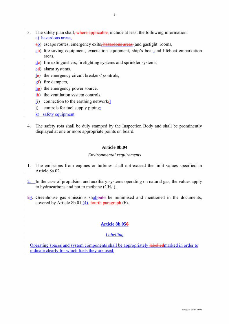
3. The safety plan shall, where applicable, include at least the following information: a) hazardous areas,
ab) escape routes, emergency exits, hazardous areas and gastight rooms,
cb) life-saving equipment, evacuation equipment, ship’s boat and lifeboat embarkation areas,
dc) fire extinguishers, firefighting systems and sprinkler systems,
ed) alarm systems,
fe) the emergency circuit breakers’ controls,
gf) fire dampers,
hg) the emergency power source,
ih) the ventilation system controls,
[i) connection to the earthing network,]
j) controls for fuel supply piping;
k) safety equipment.
4. The safety rota shall be duly stamped by the Inspection Body and shall be prominently
displayed at one or more appropriate points on board.
Article 8b.04
Environmental requirements 1. The emissions from engines or turbines shall not exceed the limit values specified in
Article 8a.02.
2. In the case of propulsion and auxiliary systems operating on natural gas, the values apply to hydrocarbons and not to methane (CH4.).
23. Greenhouse gas emissions shallould be minimised and mentioned in the documents,
covered by Article 8b.01 (4), fourth paragraph (b).
Article 8b.056
Labelling
Operating spaces and system components shall be appropriately labelledmarked in order to indicate clearly for which fuels they are used.
- 6 -
a/rvg14_15en_rev2
Annex 2
Rhine Vessel Inspection Regulations Annex T
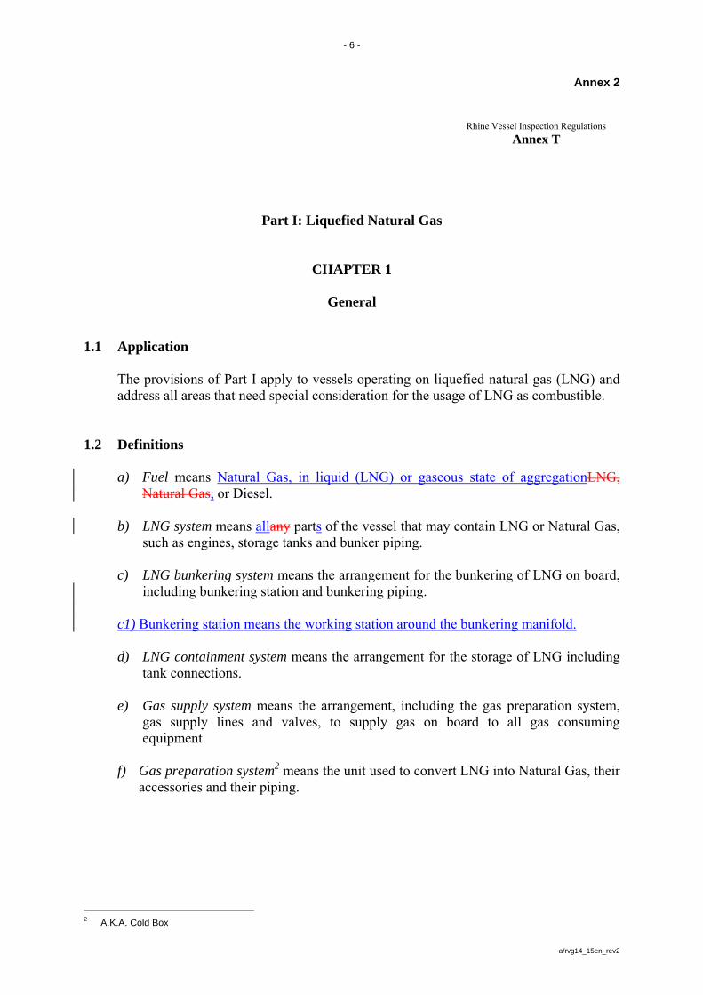
Part I: Liquefied Natural Gas
CHAPTER 1
General
1.1 Application
The provisions of Part I apply to vessels operating on liquefied natural gas (LNG) and address all areas that need special consideration for the usage of LNG as combustible.
1.2 Definitions
a) Fuel means Natural Gas, in liquid (LNG) or gaseous state of aggregationLNG, Natural Gas, or Diesel.
b) LNG system means allany parts of the vessel that may contain LNG or Natural Gas, such as engines, storage tanks and bunker piping.
c) LNG bunkering system means the arrangement for the bunkering of LNG on board,
including bunkering station and bunkering piping. c1) Bunkering station means the working station around the bunkering manifold. d) LNG containment system means the arrangement for the storage of LNG including
tank connections. e) Gas supply system means the arrangement, including the gas preparation system,
gas supply lines and valves, to supply gas on board to all gas consuming equipment.
f) Gas preparation system2 means the unit used to convert LNG into Natural Gas, their
accessories and their piping.
2 A.K.A. Cold Box
- 7 -
a/rvg14_15en_rev2
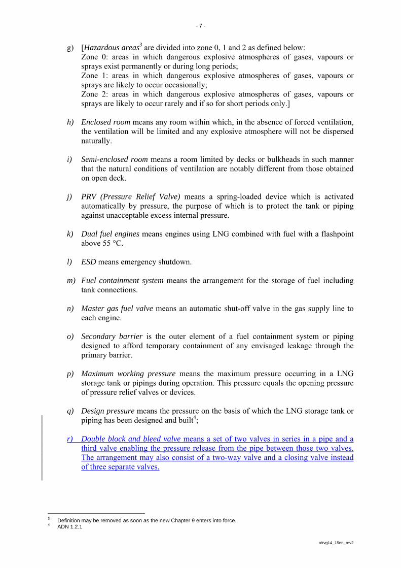
g) [Hazardous areas3 are divided into zone 0, 1 and 2 as defined below: Zone 0: areas in which dangerous explosive atmospheres of gases, vapours or sprays exist permanently or during long periods; Zone 1: areas in which dangerous explosive atmospheres of gases, vapours or sprays are likely to occur occasionally; Zone 2: areas in which dangerous explosive atmospheres of gases, vapours or sprays are likely to occur rarely and if so for short periods only.]
h) Enclosed room means any room within which, in the absence of forced ventilation,
the ventilation will be limited and any explosive atmosphere will not be dispersed naturally.
i) Semi-enclosed room means a room limited by decks or bulkheads in such manner
that the natural conditions of ventilation are notably different from those obtained on open deck.
j) PRV (Pressure Relief Valve) means a spring-loaded device which is activated
automatically by pressure, the purpose of which is to protect the tank or piping against unacceptable excess internal pressure.
k) Dual fuel engines means engines using LNG combined with fuel with a flashpoint
above 55 °C.
l) ESD means emergency shutdown. m) Fuel containment system means the arrangement for the storage of fuel including
tank connections. n) Master gas fuel valve means an automatic shut-off valve in the gas supply line to
each engine. o) Secondary barrier is the outer element of a fuel containment system or piping
designed to afford temporary containment of any envisaged leakage through the primary barrier.
p) Maximum working pressure means the maximum pressure occurring in a LNG
storage tank or pipings during operation. This pressure equals the opening pressure of pressure relief valves or devices.
q) Design pressure means the pressure on the basis of which the LNG storage tank or
piping has been designed and built4; r) Double block and bleed valve means a set of two valves in series in a pipe and a
third valve enabling the pressure release from the pipe between those two valves. The arrangement may also consist of a two-way valve and a closing valve instead of three separate valves.
3 Definition may be removed as soon as the new Chapter 9 enters into force. 4 ADN 1.2.1
- 8 -
a/rvg14_15en_rev2
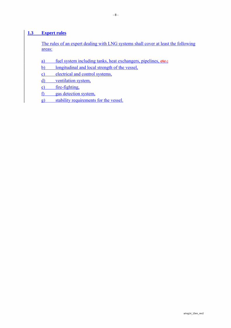
1.3 Expert rules
The rules of an expert dealing with LNG systems shall cover at least the following areas:
a) fuel system including tanks, heat exchangers, pipelines, etc.;
b) longitudinal and local strength of the vessel,
c) electrical and control systems,
d) ventilation system,
e) fire-fighting,
f) gas detection system,
g) stability requirements for the vessel.
- 9 -
a/rvg14_15en_rev2
CHAPTER 2
Vessel Arrangements and System Design 2.1 General
a) A risk assessment shall be conducted on any new or altered concept or configuration or other significant changes to ensure that risks arising from the use of LNG affecting people on board, the environment, the structural strength or the integrity of the vessel are addressed. Consideration shall be given to the hazards associated with physical layout, operation, and maintenance, following any reasonably foreseeable failure.
b) The risks shall be analysed using acceptable and recognized risk analysis
techniques and loss of function, component damage, fire, explosion, tank room flooding, vessel sinking and electric shock shall as a minimum be considered. The analysis shall ensure that risks are eliminated wherever possible. Risks which cannot be eliminated shall be mitigated as necessary. Details of risks, and the means by which they are mitigated, shall be included in the operating manual and in the safety rota.
c) Hazardous areas shall be restricted, as far as practicable, to minimize the potential
risks that might affect the safety of the vessel, persons on board, environment and equipment.
d) Equipment installed in hazardous areas shall be minimized to that required for
operational purposes and shall be suitably and appropriately certified. e) Unintended accumulation of explosive or flammable gas concentrations shall be
prevented. f) Components of the LNG system shall be protected against external damages. g) Sources of ignition in hazardous areas shall be limited to reduce the probability of
explosions. h) The LNG system shall be designed, constructed, installed, operated, maintained and
protected to ensure safe and reliable operation. i) A detailed operating manual of the LNG system, which contains practical
explanations about LNG bunkering system, LNG containment system, LNG piping system, Gas supply system, engine room, ventilation system, leakage prevention and control, monitoring and safety system as a minimum, shall be available.
The bunkering process, especially valves operation, purging, inerting and gas freeing, shall be described. The relevant method of electrical insulation during bunkering operations should be also specified in the operating manual.
ij) Bunkering arrangements shall be capable of taking on board and containing the fuel
in the required state without leakage or environmental emissions (venting) during all routine and unscheduled operations and situations including idle periods.
- 10 -
a/rvg14_15en_rev2
jk) A fire or explosion caused by released gas in fuel containment systems and engine rooms shall not render the essential machinery or equipment in other compartments inoperable.
lk) Suitable control, alarm, monitoring and shutdown systems shall be provided to
ensure safe and reliable operation. ml) Fire detection, protection and extinction measures appropriate to the hazards
concerned shall be provided. nm) The technical documentation shall permit an assessment of the compliance of the
LNG system with the applicable rules, guidelines, design standards used and the principles related to safety, availability, maintainability and reliability.
no) A single failure in the LNG system shall not lead to an unsafe or unreliable
situation.
2.2 LNG containment system
a) The LNG containment system shall be provided with a secondary barrier. No secondary barrier is required for the LNG containment systems where the probability for structural failures and leakages through the primary barrier is extremely low and can be neglected.
b) If the secondary barrier of the LNG containment system is part of the hull structure
it may be a boundary of the tank room providing necessary precautions against leakage of cryogenic liquid are being taken.
c) The LNG containment system shall be separated from engine rooms or other high
fire risk areas. d) LNG storage tanks shall be located as close as possible to the centreline of the
vessel:5
aa) For LNG storage tanks located below deck, the vessel shall have a double wall and a double bottom construction at the location of the LNG storage tank. The mean depth of the double bottoms shall not be less than 0,60m. The distance between the side wall and the inner wall of the vessel shall not be less than 1,00 m. A distance of 0,80 m may however be permitted, provided that, compared with the scantling requirements specified in the rules for construction of the expert, the following reinforcements have been made:
- 25% increase in the thickness of the deck stringer plate;
- 15% increase in the side plating thickness;
- Arrangement of a longitudinal framing system at the vessel’s side, where depth of the longitudinals shall be not less than 0,15 m and the longitudinals shall have a face plate with the cross-sectional area of at least 7,0 cm2.
5 Reference ADN – 9.3.2.11.7
- 11 -
a/rvg14_15en_rev2
- The stringer or longitudinal framing systems shall be supported by web frames, and like bottom girders fitted with lightening holes, at a maximum spacing of 1,80 m. These distances may be increased if the longitudinals are strengthened accordingly.
bb) For LNG storage tanks located on open deck the distance shall be at least B/5. By way of derogation, the distances for LNG storage tanks below deck may be observed, provided that an equal level of protection against collision can be proved.
e) The LNG storage tank shall be an independent tank designed in accordance with
EN 13530, EN 13458-2 : 2002 in combination with dynamic load, the IGC-Code (type C tank), the ADN or another appropriate standard to the satisfaction of the competent authority.
f) Tank connections shall be mounted above the highest liquid level in the tanks.
However, connections below the highest liquid level may be accepted after special consideration by the competent authority.
g) LNG storage tanks with a connection below the highest liquid level shall be fitted
with drip trays below the tank which shall be of sufficient capacity to contain the volume which could escape in the event of a pipe connection failure. The material of the drip tray shall be stainless steel, and there shall be sufficient separation or isolation so that the hull or deck structures are not exposed to unacceptable cooling, in case of leakage of LNG.
h) The location and construction of the LNG containment system and other equipment
on open deck shall assure sufficient ventilation. Accumulation of escaped Natural Gas shall be prevented.
i) Spaces surrounding LNG storage tanks shall be filled with suitable dry air and be
maintained in this condition with dry air provided by suitable air drying equipment. This is only applicable for LNG storage tanks where condensation and icing due to cold surfaces is an issue.
j) Each LNG storage tank is to be fitted with at least two PRV’s that can prevent an
overpressure if one of the valves is closed off due to malfunctioning, leakage or maintenance.
k) If fuel release into the vacuum space of a vacuum insulated LNG storage tank
cannot be excluded, the vacuum space shall be protected by a suitable pressure relief device. LNG storage tanks located in enclosed rooms shall be connected to a vent system. For LNG storage tanks located on open deck a direct release into the atmosphere may be accepted.
l) The exhaust outlets of the PRV’s shall be located not less than 2 m above the deck
at a distance of not less than 6 m from the accommodation, passenger areas and from the work sites located outside the hold or the cargo area of a motor tankercargo area. This height may be reduced when within a radius of 1 m round the PRV outlet there is no equipment, no work is being carried out and signs indicate the area.
- 12 -
a/rvg14_15en_rev2
m) Arrangements shall be made to safely empty the LNG storage tanks. These
arrangements shall be available when the LNG system is shut down. n) It shall be possible to purge gas and vent LNG storage tanks including gas piping
systems. Inerting shall be performed with, e.g. , nitrogen or argon prior to venting to avoid an explosion hazardous atmosphere in LNG storage tanks and gas piping.
o) LNG storage tanks' pressure and temperature shall be maintained at all times within
their design range.
In determining the maximum working pressure, due attention is to be given to hydrostatic pressures if these cause the loads on the walls to be increased by 5 % or more.
The LNG system shall be capable of maintaining actual working pressure in LNG storage tank below the maximum working pressure for a period of 15 days. It shall be assumed that LNG storage tank was filled at normal filling level and at starting working pressure and that the vessel remains in idle condition
p) LNG storage tanks shall be electrically bonded to the vessel's structure.
2.3 Engine rooms
Engine rooms shall be gas safe or designed as ESD protected. 2.3.1 Requirements for gas safe engine rooms:
a) Arrangements in engine rooms shall be such that the rooms are considered gas safe under all conditions, normal as well as abnormal conditions, e.g. inherently gas safe. A single failure within the LNG system shall not lead to a concentration over 20% of the lower explosive limit (LEL) into the engine room.
b) All gas piping within engine room boundaries shall be enclosed in a gas tight
enclosure, e.g. double wall piping or ventilated ducting. The gastight enclosure concept can be replaced by a sufficient increased ventilation of the engine room.
c) In case one barrier fails, the gas supply in that part of the LNG system shall be shut
down. d) The ventilation system of the engine room shall be independent from the ventilation
system for double wallpiping, ventilated ducting and for gas valve units in gas safe engine rooms.
- 13 -
a/rvg14_15en_rev2
2.3.2 Requirements for the ESD protected engine rooms:
a) Arrangements in engine rooms shall be such that the rooms are considered non-hazardous under normal conditions, but under certain abnormal conditions may have the potential to become hazardous. In the event of abnormal conditions involving gas hazards, emergency shutdown of non-safe equipment (ignition sources) and gas machinery is to be automatically executed while equipment or machinery in use or active during these conditions are to be of a certified safe type.
b) Measures shall be applied to protect against explosion, damage of areas outside of
the engine room and ensure redundancy of power supply.
c) Gas piping within engine rooms may be accepted without a gastight enclosure on the following conditions:
1. Engines for generating propulsion power and electric power shall be located in
two or more engine rooms not having any common boundaries unless it can be documented that a single failure will not affect both rooms.6
2. A fixed gas detection system arranged to automatically shutdown the gas
supply to the engine room concerned and to disconnect all non-explosion protected equipment or installations shall be fitted.
d) Distribution of engines between the different engine rooms shall be such that in the
case of shutdown of gas supply to any one engine room it is possible to maintain sufficient power for manoeuvrability and for essential power supply for operational purposes.
e) ESD protected engine rooms shall have ventilation with a capacity of at least 15 air
changes per hour of the gross volume of the engine room. If gas is detected in the engine room, the number of air changes shall automatically be increased to 30 air changes per hour. The ventilation system shall ensure a good air circulation in all engine rooms, and in particular ensure that any formation of gas pockets in the room are detected.
2.4 LNG piping systems
a) LNG and Natural Gas piping shall not be led through other engine rooms or non-
hazardous areas of the vessel. Alternatively, double wall gas piping or a ventilated duct may be approved, provided the danger of mechanical damage is negligible. The gas piping shall have no discharge sources and the room shall be equipped with a gas detection system.
b) Fuel piping shall not be located less than 1 m from the vessel’s side and 600 mm
from the bottom and shall not be located in the double hull or double bottom.
6 Considered as good shipbuilding practice
- 14 -
a/rvg14_15en_rev2
c) All piping or components for LNG which can be isolated in a liquid full condition
shall be provided with PRV’s. d) Piping shall be electrically bonded to the vessel's structure. e) Low temperature piping shall be thermally isolated from the adjacent hull structure,
where necessary. Protection against physicalaccidental contact shouldshall be provided.
f) The design pressure of piping shall not be less than 150 % of the working pressure.
The working pressure of piping inside spaces shall not exceed 10 bar. The design pressure of the outer pipe or duct of gas piping systems shall not be less than the design pressure of the inner gas pipe.
g) Gas piping in ESD-protected engine rooms shall be located as far away as
practicable from the electrical installations and tanks containing flammable liquids.
2.5 Bilge systems and drip trays
a) Bilge systems for areas where LNG or Natural Gas can be present shall be independent and separate from the bilge system of areas where LNG or Natural Gas cannot be present. The bilge system shall not lead to pumps in non hazardous areas.
b) Suitable drip trays shall be fitted where leakage may occur which can cause damage
to the vessel’s structure or where limitation of the area which is effected from a spill is necessary.
c) Where the LNG containment system does not require a secondary barrier, suitable
drainage arrangements for the tank rooms that are not connected to the engine rooms shall be provided. Means of detecting any leakage shall be provided.
c) Where there is a secondary barrier, suitable drainage arrangements for dealing with
any leakage into the interbarrier spaces shall be provided. Means of detecting such leakage shall be provided.
2.6 Arrangement of entrances and other openings
a) Entrances and other openings from a non-hazardous area to a hazardous area shall only be permitted to the extent necessary for operational reasons. For these entrances and openings an air lock shall be provided.
b) Air locks shall be suitable for vessels with regard to their dimension. c) Air locks shall be mechanically ventilated at an overpressure relative to the adjacent
hazardous area. Doors shall be of self-closing type. d) The air lock has to be designed in a way that no gas can be released to safe spaces
in case of the most critical event in the gas dangerous space separated by the air lock. The events shall be evaluated in the risk analysis according to 2.1. a)
- 15 -
a/rvg14_15en_rev2
e) Air locks shall provide free and easy passage and shall not be used for other
purposes. f) An acoustic and optical alarm shall be given on both sides of the air lock to indicate
if more than one door is moved from the closed position or when gas is detected in the air lock.
g) Essential equipment required for safety shall not be de-energized and shall be of a
certified safe type. This may include lighting, fire detection, public address, general alarms systems.
2.7 Ventilation systems
a) Ventilators in hazardous areas shall be of a certified safe type. b) Electric motors driving ventilators shall comply with the required explosion
protection in the installation area. c) Any loss of the required ventilating capacity shall give an acoustic and optical
alarm at a permanently manned location (e.g. wheelhouse). d) Any ducting used for the ventilation of hazardous areas shall be separate from that
used for the ventilation of non-hazardous areas. e) Required ventilation systems shall consist of independent fans, each of sufficient
capacity, to avoid any gas accumulation. f) Air inlets for hazardous rooms shall be taken from non-hazardous areas. g) Air inlets for non-hazardous rooms shall be taken from non-hazardous areas at least
1,5 m away from the boundaries of any hazardous area. h) Where the inlet duct passes through a hazardous room, the duct shall have over-
pressure relative to this room, unless mechanical integrity and gas tightness of the duct will ensure that gases will not leak into it.
i) Air outlets from hazardous rooms shall be located in an open area which is of the
same or less hazard than the ventilated room. j) Air outlets from non-hazardous rooms shall be located outside hazardous areas. k) In enclosed rooms the ventilation exhaust ducts shall be located at the top of these
rooms. Air inlets shall be located at the bottom.
- 16 -
a/rvg14_15en_rev2
2.8 LNG bunkering system
a) The LNG bunkering system shall be so arranged that no gas is discharged to the
atmosphere during filling of LNG storage tanks. b) The LNG bunkering station shall be located on open deck so that sufficient natural
ventilation is provided. c) The bunkering manifold shall be so positioned and arranged that any damage to the
gas piping does not cause damage to the vessel's LNG containment system. d) Suitable means shall be provided to relieve the pressure and remove liquid contents
from pump suctions and bunker piping. e) Hoses used for LNG transfer shall be compatible with LNG and suitable for the
LNG temperature. f) Hoses used for LNG transfer shall be designed for a bursting pressure not less than
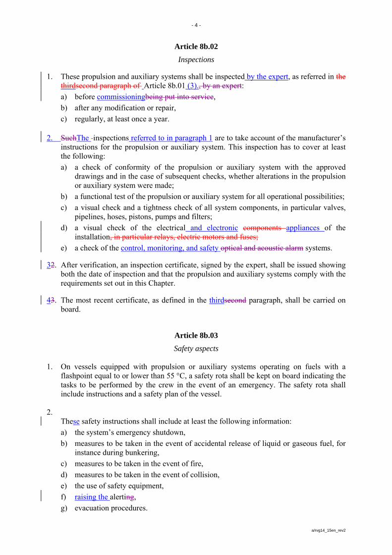
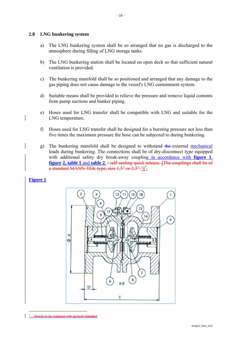
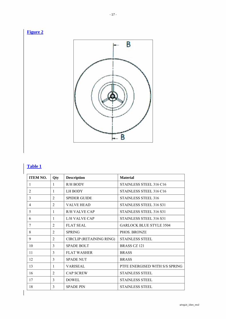
five times the maximum pressure the hose can be subjected to during bunkering. g) The bunkering manifold shall be designed to withstand the external mechanical
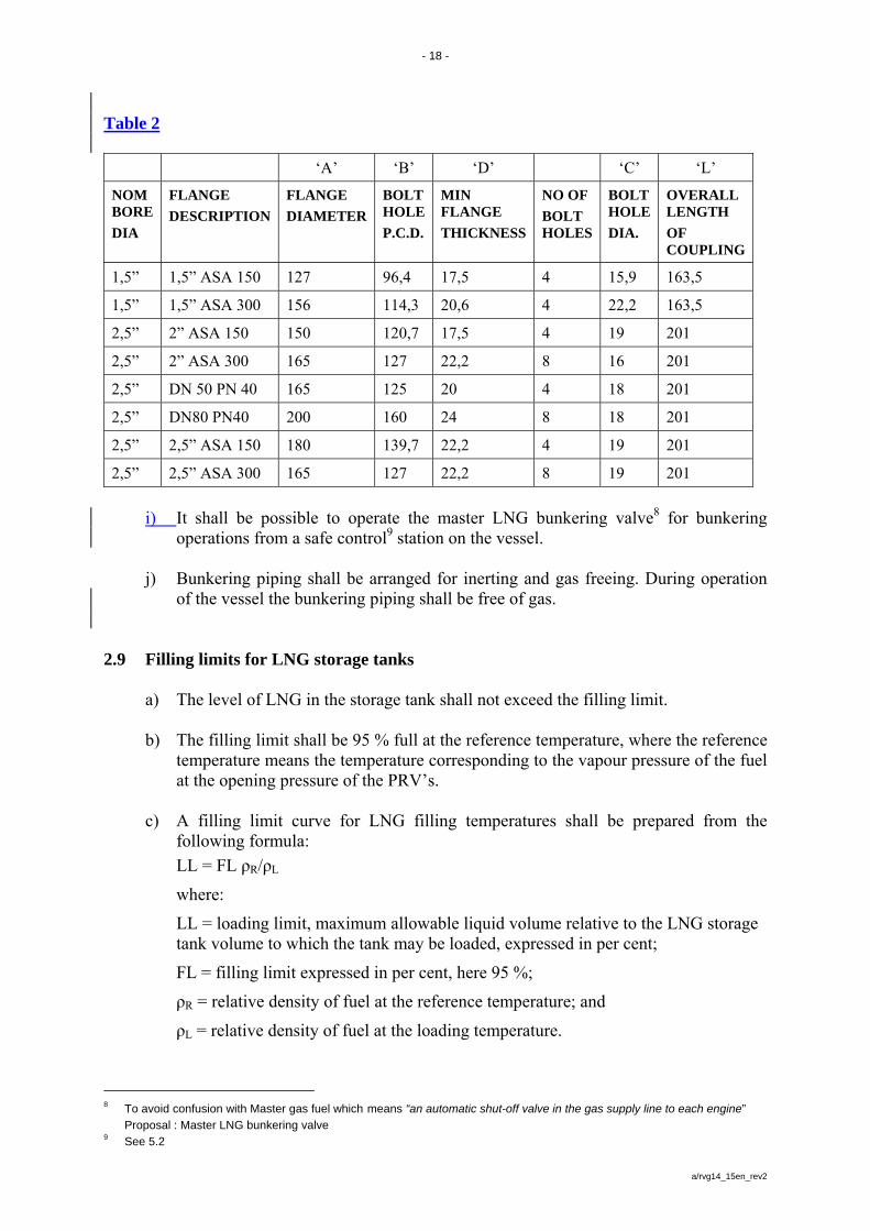
loads during bunkering. The connections shall be of dry-disconnect type equipped with additional safety dry break-away coupling in accordance with figure 1, figure 2, table 1 and table 2. / self-sealing quick release. [The couplings shall be of a standard MANN-TEK type, size 1,5” or 2,5”.”]7.
Figure 1
7 Needs to be replaced with general standard
- 17 -
a/rvg14_15en_rev2
Figure 2
Table 1
ITEM NO. Qty Description Material
1 1 R/H BODY STAINLESS STEEL 316 C16
2 1 LH BODY STAINLESS STEEL 316 C16
3 2 SPIDER GUIDE STAINLESS STEEL 316
4 2 VALVE HEAD STAINLESS STEEL 316 S31
5 1 R/H VALVE CAP STAINLESS STEEL 316 S31
6 1 L/H VALVE CAP STAINLESS STEEL 316 S31
7 2 FLAT SEAL GARLOCK BLUE STYLE 3504
8 2 SPRING PHOS. BRONZE
9 2 CIRCLIP (RETAINING RING) STAINLESS STEEL
10 3 SPADE BOLT BRASS CZ 121
11 3 FLAT WASHER BRASS
12 3 SPADE NUT BRASS
13 1 VARISEAL PTFE ENERGISED WITH S/S SPRING
16 2 CAP SCREW STAINLESS STEEL
17 3 DOWEL STAINLESS STEEL
18 3 SPADE PIN STAINLESS STEEL
- 18 -
a/rvg14_15en_rev2
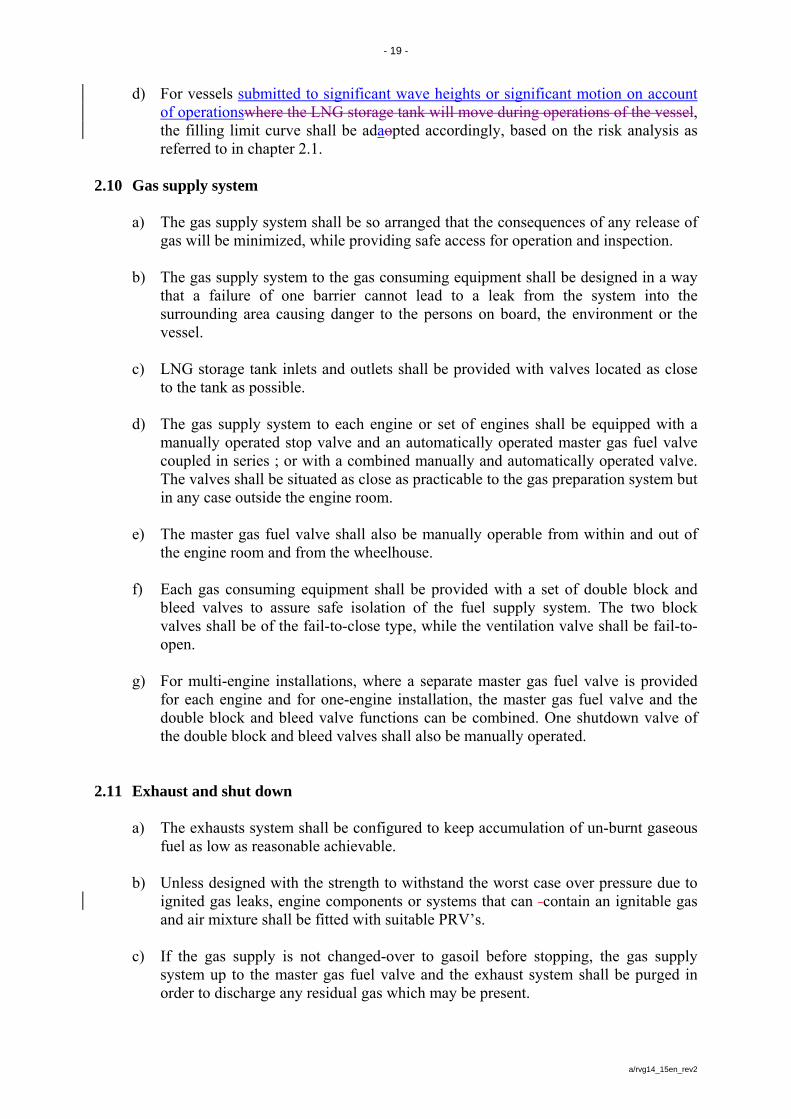
Table 2
‘A’ ‘B’ ‘D’ ‘C’ ‘L’
NOM BORE
DIA
FLANGE
DESCRIPTION
FLANGE
DIAMETER
BOLT HOLE
P.C.D.
MIN FLANGE
THICKNESS
NO OF
BOLT HOLES
BOLT HOLE
DIA.
OVERALL LENGTH
OF COUPLING
1,5” 1,5” ASA 150 127 96,4 17,5 4 15,9 163,5
1,5” 1,5” ASA 300 156 114,3 20,6 4 22,2 163,5
2,5” 2” ASA 150 150 120,7 17,5 4 19 201
2,5” 2” ASA 300 165 127 22,2 8 16 201
2,5” DN 50 PN 40 165 125 20 4 18 201
2,5” DN80 PN40 200 160 24 8 18 201
2,5” 2,5” ASA 150 180 139,7 22,2 4 19 201
2,5” 2,5” ASA 300 165 127 22,2 8 19 201
i) It shall be possible to operate the master LNG bunkering valve8 for bunkering
operations from a safe control9 station on the vessel. j) Bunkering piping shall be arranged for inerting and gas freeing. During operation
of the vessel the bunkering piping shall be free of gas.
2.9 Filling limits for LNG storage tanks
a) The level of LNG in the storage tank shall not exceed the filling limit. b) The filling limit shall be 95 % full at the reference temperature, where the reference
temperature means the temperature corresponding to the vapour pressure of the fuel at the opening pressure of the PRV’s.
c) A filling limit curve for LNG filling temperatures shall be prepared from the
following formula:
LL = FL ρR/ρL
where:
LL = loading limit, maximum allowable liquid volume relative to the LNG storage tank volume to which the tank may be loaded, expressed in per cent;
FL = filling limit expressed in per cent, here 95 %;
ρR = relative density of fuel at the reference temperature; and
ρL = relative density of fuel at the loading temperature.
8 To avoid confusion with Master gas fuel which means “an automatic shut-off valve in the gas supply line to each engine”
Proposal : Master LNG bunkering valve 9 See 5.2
- 19 -
a/rvg14_15en_rev2
d) For vessels submitted to significant wave heights or significant motion on account of operationswhere the LNG storage tank will move during operations of the vessel, the filling limit curve shall be adaopted accordingly, based on the risk analysis as referred to in chapter 2.1.
2.10 Gas supply system
a) The gas supply system shall be so arranged that the consequences of any release of gas will be minimized, while providing safe access for operation and inspection.
b) The gas supply system to the gas consuming equipment shall be designed in a way
that a failure of one barrier cannot lead to a leak from the system into the surrounding area causing danger to the persons on board, the environment or the vessel.
c) LNG storage tank inlets and outlets shall be provided with valves located as close
to the tank as possible. d) The gas supply system to each engine or set of engines shall be equipped with a
manually operated stop valve and an automatically operated master gas fuel valve coupled in series ; or with a combined manually and automatically operated valve. The valves shall be situated as close as practicable to the gas preparation system but in any case outside the engine room.
e) The master gas fuel valve shall also be manually operable from within and out of
the engine room and from the wheelhouse. f) Each gas consuming equipment shall be provided with a set of double block and
bleed valves to assure safe isolation of the fuel supply system. The two block valves shall be of the fail-to-close type, while the ventilation valve shall be fail-to-open.
g) For multi-engine installations, where a separate master gas fuel valve is provided
for each engine and for one-engine installation, the master gas fuel valve and the double block and bleed valve functions can be combined. One shutdown valve of the double block and bleed valves shall also be manually operated.
2.11 Exhaust and shut down
a) The exhausts system shall be configured to keep accumulation of un-burnt gaseous fuel as low as reasonable achievable.
b) Unless designed with the strength to withstand the worst case over pressure due to
ignited gas leaks, engine components or systems that can contain an ignitable gas and air mixture shall be fitted with suitable PRV’s.
c) If the gas supply is not changed-over to gasoil before stopping, the gas supply
system up to the master gas fuel valve and the exhaust system shall be purged in order to discharge any residual gas which may be present.
- 20 -
a/rvg14_15en_rev2
e) A means shall be provided to monitor and detect incorrect operation of the ignition system, poor combustion or mis-firing that may lead to unburnt gas in the exhaust system during operation. In the event that it is detected, the gas supply system shall be shut down. In cases where there is only one engine it shall be possible to manually over-ride the shutdown device.
f) The exhaust pipes of gas or dual fuel engines shall not be connected to the exhaust
pipes of other engines or systems. g) In case of a normal stop or an ESD, the gas supply system shall be shut off not later
than the ignition source. It shall not be possible to shut off the ignition source without first or simultaneously closing the gas supply to each cylinder or to the complete engine.
h) In case of shut-off of the gas supply system in a dual fuel engine, the engine shall
be capable of continuous operation on gasoil only without interruption.
CHAPTER 3
Fire Safety 3.1 General
a) The gas preparation system shall be regarded as an engine room for fire protection purposes.
b) A cofferdam of at least 600 mm wide that can be filled with water within 30
minutes shall be considered equivalent to class A-60 insulation.
3.2 Fire alarm system
a) A suitable fixed fire alarm system10 shall be provided for all rooms of the LNG system where fire cannot be excluded.
b) Smoke detectors alone shall not be considered sufficient for rapid detection of a
fire. c) The fire detection system shall have the means to identify each detector
individually. 3.3 Fire protection
a) LNG storage tanks located on deck shall be shielded with class A-60 insulation from accommodation, engine rooms and escape routes, where the distance is less then 3m. LNG storage tanks shall also be segregated from cargo in accordance with the requirements of the ADN.
10 Administrative instruction 17
- 21 -
a/rvg14_15en_rev2
b) The LNG storage tank room boundaries and ventilation trunks to such spaces below the bulkhead deck shall be constructed to class A-60 standard. However, where the room is adjacent to tanks, voids, auxiliary engine rooms of little or no fire risk, sanitary and similar spaces, the insulation standard may be reduced to class A-0.
c) The bunkering station shall be separated by class A-60 insulation from engine
rooms, accommodation and high fire risk spaces. 3.4 Fire prevention and cooling
a) A water spray system shall be installed for cooling and fire prevention to cover exposed parts of LNG storage tank(s) located on open deck.
b) The water spray system may be part of the fire main system provided that the
required fire pump capacity and working pressure are sufficient for operation of both the required numbers of hydrants and hoses and the water spray system simultaneously.
c) When the LNG storage tank is located on open deck, isolating valves shall be fitted
in the fire main in order to isolate damaged sections of the main. Isolation of a section of fire main shall not deprive the fire line ahead of the isolated section of water.
d) The water spray system shall also provide coverage for boundaries of the
superstructures, unless the tank is located 3metres or more from the boundaries. e) The water spray system shall be designed to cover all areas as specified above with
an application rate of 10 l/min/m2 for horizontal projected surfaces and 4 l/min/m2 for vertical surfaces.
f) The water spray system shall be fitted with a connection device for supply from the shore.
g) A connection to the vessel’s fire main through a screw-down non-return valve shall
be provided. h) The water spray system shall be capable of being put into operation from the
wheelhouse and from the deck. i) The nozzles shall be of an approved full bore type and they should be arranged to
ensure an effective distribution of water throughout the space being protected.
3.5 Fire extinguishing
Two additional portable dry powder fire extinguishers of at least 12 kg capacity shall be located near the bunkering station.

- 22 -
a/rvg14_15en_rev2
CHAPTER 4
Electrical Systems
a) Equipment for hazardous areas shall be of a certified safe type. b) Electrical generation and distribution systems and associated control systems shall
be designed such that a single fault will not result in the release of gas. c) The lighting system in hazardous areas shall be divided between at least two branch
circuits. All switches and protective devices shall interrupt all poles or phases and shall be located in a non-hazardous area.
d) Submerged gas pump motors and their supply cables may be fitted in LNG
containment systems. Arrangements shall be made to alarm in low liquid level and automatically shut down the motors in the event of low-low liquid level. The automatic shutdown may be accomplished by sensing low pump discharge pressure, low motor current, or low liquid level. This shutdown shall give an acoustic and optical alarm in the wheel house. Gas pump motors shall be capable of being isolated from their electrical supply during gas-freeing operations.
- 23 -
a/rvg14_15en_rev2
CHAPTER 5
Control, Monitoring and Safety Systems
5.1 General
a) The gas supply system shall be fitted with its own set of independent gas control, gas monitoring and gas safety systems. All elements11 of these systems shall be capable of being functionally tested.
b) The gas safety system shall close down the gas supply system automatically, upon
failure in systems essential for the safety and upon fault conditions which may develop too fast for manual intervention.
For ESD protected engine rooms the gas safety system shall shut down gas supply upon gas leakage and in addition disconnect all non-explosion protected equipment in the engine room.
c) The safety functions shall be arranged in a dedicated gas safety system that is
independent of the gas control system d) Instrumentation devices shall be fitted to allow a local and a remote reading of
essential parameters to ensure a safe operation of the whole LNG system including bunkering.
5.2 LNG bunkering system and LNG containment system monitoring
a) Each LNG storage tank shall be fitted with at least two liquid level gauges, which shall be arranged so that they can be maintained in an operational condition.
b) Overflow control
aa) Each LNG storage tank shall be fitted with a high liquid level alarm operating independently of other liquid level indicators and giving an acoustic and optical alarm when activated.
bb) An additional sensor operating independently of the high liquid level alarm
shall automatically actuate a shutoff valve in a manner that will both avoid excessive liquid pressure in the bunkering piping and prevent the tank from becoming liquid full.
c) The pressure indicators shall be clearly marked with the maximum working
pressure of the LNG storage tank. d) Each gas pump discharge line and each liquid and vapour gas manifold shall be
provided with at least one local pressure indicator.
11 Taken from 5.2, b, 3. Is this valid?
- 24 -
a/rvg14_15en_rev2
e) Rooms and interbarrier spaces without open connection to the atmosphere shall be
provided with at least one pressure indicator. f) A high-pressure alarm and, if vacuum protection is required, a low-pressure alarm
shall be provided.
g) Control of the bunkering shall be possible from a safe control station12 remote from the bunkering station. At this control station the LNG storage tank pressure and level shall be monitored. Overfill alarm, high and low-pressure alarm and automatic shutdown shall be indicated at this control station.
h) If the ventilation in the ducting enclosing the bunkering lines stops, an acoustic and
optical alarm shall be actuated at the control station. i) If gas is detected in the ducting enclosing the bunkering piping an acoustic and
optical alarm and emergency shut-down shall be actuated at the control station. j) Appropriate and sufficient suitable protective clothing and equipment for bunkering
operations shall be available on board. 5.3 Engine operation monitoring
Indicators shall be fitted in the wheelhouse and the engine room for: a) operation of the engine in case of a gas-only engine; or b) operation and mode of operation of the engine in the case of a dual fuel engine.
5.4 Gas detection
a) Permanently installed gas detectors shall be fitted in:
1. tank connection areas
2. ducts around gas piping
3. engine rooms containing gas piping, gas equipment or gas consuming equipment
4. the room containing the gas preparation system
5. other enclosed rooms containing gas piping or other gas equipment without ducting
6. other enclosed or semi-enclosed rooms where gas vapours may accumulate including inter-barrier spaces and tank rooms of independent LNG storage tanks other than type C
7. air locks
8. engine rooms where gas can be present
9. ventilation inlets to accommodation and engine rooms.
b) The number and redundancy of gas detectors in each room shall be considered taking size, layout and ventilation of the room into account.
12 See 2.8 letter i)
- 25 -
a/rvg14_15en_rev2
c) Gas detection equipment shall be located where gas may accumulate and in the ventilation outlets of these rooms. A physical smoke test shall be used to find the best arrangement.
d) Gas detection equipment shall be designed, installed and tested in accordance with
a recognized standard, such as IEC 60079-29-1 – Explosive atmospheres – Gas detectors – Performance requirements of detectors for flammable detectors or administrative instruction 24.
e) An acoustic and optical alarm shall be activated before the gas concentration
reaches 20 % of the lower explosive limit. The gas safety system shall be activated at 40 % of the lower explosive limit.
f) Acoustic and optical alarms from the gas detection equipment shall be actuated in
the wheelhouse. 5.5 Safety functions of gas supply systems
a) The total loss of ventilation in an engine room for a single fuelled gas system shall, additionally to what is prescribed in table 1, lead to one of the following actions:
1. for a gas electric propulsion system with more than one engine room:
Another engine in the other engine room shall start and the affected engine shall be shutdown automatically; or
2. for a direct propulsion system with more than one engine room: The engine in
the room with defect ventilation shall be manually shutdown, if at least 40 % propulsion power is still available after such a shutdown.
b) If there is only one engine room for gas-fuelled engines and ventilation in one of
the enclosed ducts around the gas piping is lost, the master gas fuel and double block and bleed valves in that supply piping shall close automatically provided the other gas supply unit is ready to deliver.
c) If the gas supply system is shut off due to activation of an automatic valve, it shall
not be opened until the reason for the disconnection is ascertained and the necessary actions taken. Instructions to this effect shall be placed at a prominent position at the control station for the shut-off valves in the gas supply piping.
d) If the gas supply system is shut off due to a gas leak, it shall not be opened until the
leak has been found the necessary actions taken. Instructions to this effect shall be placed at a prominent position in the engine room.
e) The gas supply system shall be arranged for manual remote emergency stop from
the following locations as applicable: 1. wheelhouse; 2. control station of the bunkering station 3. any permanently manned location.
- 26 -
a/rvg14_15en_rev2
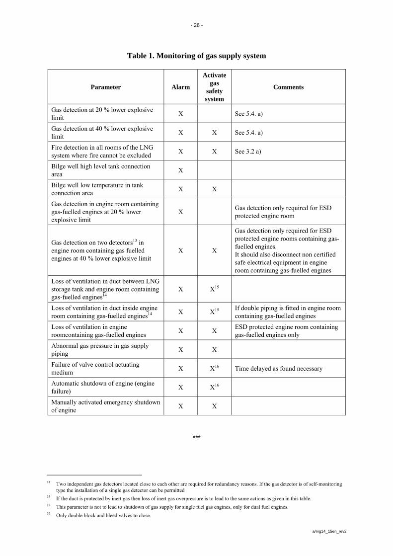
Table 1. Monitoring of gas supply system
Parameter Alarm
Activate gas
safety system
Comments
Gas detection at 20 % lower explosive limit
X See 5.4. a)
Gas detection at 40 % lower explosive limit
X X See 5.4. a)
Fire detection in all rooms of the LNG system where fire cannot be excluded
X X See 3.2 a)
Bilge well high level tank connection area
X
Bilge well low temperature in tank connection area
X X
Gas detection in engine room containing gas-fuelled engines at 20 % lower explosive limit
X Gas detection only required for ESD protected engine room
Gas detection on two detectors13 in engine room containing gas fuelled engines at 40 % lower explosive limit
X X
Gas detection only required for ESD protected engine rooms containing gas-fuelled engines. It should also disconnect non certified safe electrical equipment in engine room containing gas-fuelled engines
Loss of ventilation in duct between LNG storage tank and engine room containing gas-fuelled engines14
X X15
Loss of ventilation in duct inside engine room containing gas-fuelled engines14
X X15
If double piping is fitted in engine room containing gas-fuelled engines
Loss of ventilation in engine roomcontaining gas-fuelled engines
X X ESD protected engine room containing gas-fuelled engines only
Abnormal gas pressure in gas supply piping
X X
Failure of valve control actuating medium
X X16 Time delayed as found necessary
Automatic shutdown of engine (engine failure)
X X16
Manually activated emergency shutdown of engine
X X
***
13 Two independent gas detectors located close to each other are required for redundancy reasons. If the gas detector is of self-monitoring
type the installation of a single gas detector can be permitted 14 If the duct is protected by inert gas then loss of inert gas overpressure is to lead to the same actions as given in this table.
15 This parameter is not to lead to shutdown of gas supply for single fuel gas engines, only for dual fuel engines.
16 Only double block and bleed valves to close.


![FREEPORT LNG TERMINALfreeportlng.com/files/docs/FreeportMarOpsManual2Dock_041520.pdf · FREEPORT LNG TERMINAL FREEPORT MARINE OPERATIONS MANUAL [04/15/20]5 5.4 BERTH EQUIPMENT 33](https://img.pdfslide.us/doc/110x75/5f7f2ea2a3bc761fb95b3549/freeport-lng-freeport-lng-terminal-freeport-marine-operations-manual-0415205.jpg)