Embed Size (px)
Citation preview

£5c 1°C -Ofl
V7 /WecS
DOEfER/3072-56September30, 1989
Proposal to the SSC Laboratory
for Researchand Developmentof
a Straw-TubeTracking Subsystem
C. Lu, J.G. Heinrich andK.T. McDonald*
JosephHenryLaboratories,Princeton University,Princeton,NJ 08544
R. Burnsteinand H. Rubin
illinois Instituteof Technology,Chicago, IL 60616
D.T. Hackworth,J.W. Bartell, Jr., and J. SzedonWestinghouseElectric Corporation,Scienceand TechnologyCenter,Pittsburgh, PA 15235
Abstract
We proposean R&D programto developa straw-tubetracking systemfor useat theSSC.It emphasizesprecisionresolutionandcouldbe locatedin the volume 10-100cm fromthe beampipe. Thesefeaturesarecompatiblewith runningat an intermediateluminosity,£ 1032 cm2sec1,appriopriatefor an experimentsuchat theBottom Collider Detectorthat requiresdetailedpartide analysisat transversemomentaless than 10 0eV/c. Thepresentproposal covers only one year of an ongoing programto producea l0007tubeprototypesystemin 1990, followed by a 10,000-tubesystemin 1991. Therearethreepartsto the proposal:
1. Prototypeconstructionand testing at Princetonand lIT, *325k;
2. A Manufacturingfeasibility study by Westinghouse,*218k;
3. VLSI chip developmentwith the WestinghouseSIMOX process,*170k.
* Contactperson

I. ExecutiveSummary
We proposean R&D programto developa straw-tubetrackingsystemfor useat theSSC. It emphasizesprecisionresolution 40 pm per tube and could be located in thevolume 10-100 cm from the beampipe. Thesefeaturesarecompatiblewith running at anintermediateluminosity,£ 1032 cm2seC1,appriopriatefor an experimentsuchat theBottom Collider Detector that requiresdetailedpartide analysisat transversemomentaless than10 0eV/c.
The presentproposalcoversonly one yearof an ongoingprogram:
1990: The periodof the presentproposal.- Producea 1000-tubeprototypesystemand test this in the M-Test line at Fermilab;- Producefront-end preamp/shaper/discrichips for the 1000 tubes,requiring an opti
mzedrun of the Bipolar designof U. Penn;- Initiate a manufacturingfeasibility study with the goal of industrial productionof
chambersin 1991;- Investigatethe applicability of the SIMOX VLSI processto fast-pulseanalog+ digital
front-endelectronics
1991:- Producea 10,000-tubesystem to be testedin the CO intersectat Fermilab. It is
expectedthat this will be doneby industry;- ProduceVLSI electronicsfor this systemthat includesboth thepreamp/shaper/discri
andthe TDC functions,either in a Bi-CMOS hybrid or in the SIMOX technology;.
1992-1993:- Producea 50,000-tubesystemfor testing at the CO intersectat Fermilab in 1993.
The work in 1990 divides into threetasks: -
1. Prototypeconstructionand testing at Princetonand lIT, 1325k. This includesproductionof the Bipolar front-endchips. Of thesefunds, 110k aretravelandoperatingexpensesof the lIT group.
2. A Manufacturingfeasibility study by Westinghouse,*218k;
3. VLSI chip developmentwith the WestinghouseSIMOX process,*170k.
Furthercost breakdownsaresummarizedin the Tableof Contents,andsupportedbydetails in ChapterIV.
1

Tableof Contents
The dollar amountsshownin boldface associatedwith certain sectionsindicate thefunding requestof the presentproposal.
I. ExecutiveSummary 1
II. The Opportunity for B Physicsat the SSC 2
III. Overview of the Straw-TubeChamberSystem 4
IV. The R&D Program 7Overview 7
1. Constructionof thestrawtubes 7a. Cathodenietallization*6k 8b. Straw-tubeimpedance 8c. Winding the tubes*10k 8d. Establishmentof a cleanroomfacility *60k 9e. Improvementof support facilities *35k 10
2. Anodewke 10a. Wire instability 10b. Gasgain vs. wire diameter 11c. Anode-wireresistance 11d. Testsof variouswire diameters*2k 11e. Test of wire tension*3k 12
3. End plugs andend plates 12a. Ohio-Statedesignof end plugs *45k 12b. Assemblyprocedure*5k 13c. Macor end-plate/gasmanifolds*10k 13d. Electrical layout *5k 14
4. Choiceof chambergas 15a. Resolution 15b. Ageing 16c. Chemicalaggressivity*7k 16d. Gas distribution system*8k 17e. Heat load due to ionization 17f. Heat load of front-endelectronics 18g. Pressurization 18h. Lorentz angle 18
5. Front-end-electronicsdevelopment 18a. Customrun of the AT&T bipolar design*50k 19b. Testingandmountingof the chips *15k 19
6. WestinghouseSIMOX process 19a. The SIMOX approachto IncreasingIC Functionality 20b. Westinghousecapability 21c. Budget*170k 23
I

6. TDC development.a. The Penn/Leuvendesignb. The KEK TMC chip
7. Manufacturingfeasibility studya. Statementof workb. Budgetsummary*218k
8. Simulationof physicsperformance9. Testprogram
a. Gain studies*4kb. Resolutionstudies*10kc. Pulsedx-ray test facility *25kd. Fixed-targettest*25k
232324242426262727272728
Appendix A. RadiationLengthsof the Straw-Thbes 29
Appendix B. Straw-TubeLifetime 30
Appendix C. A Surveyof GasMixtures 321. DimethyletherDME 322. Ar/CO2 Mixtures 373. CF4 40
References 45
‘I

II. The Opportunity for B Physicsat a Hadron Collider
We areembarkingon a long-rangeprogramwith the goal of detailedinvestigationofCP violation in the B-B system.’ Of all known phenomena,we believethat OP violationis the dearestindication that new physicsis to be found at energyscalesabove 1 TeV.Thegreatestopportunity to explorethis subjectat presentenergiesis at a hadroncollidersuchas the550: the cross-sectionfor B-mesonproductionis about io timeslargerat theSSCthan at the T45 resonanceat an e+r collider.
Becausethe B lifetime is 1 picosecond,a B mesontravelsfar enoughbefore its decaythat thedecayproductsmaybe isolatedfrom the primarypp interaction. A silicon vertexdetectorcan then providea signal for the B of quality similar to that in the nominallycleanerenvironmentof an e4c collider. The vertexdetectorwill be surroundedby tracking chambersandparticleidentificationin a spectrometerbasedon a large1-Tesladipolemagnet,sketchedin Fig. 1.
Fig-I. View oft B-physicsexperiment at the SSC. The straw-tube chambersystem is the rectangularstructure shown in the center with the 14 vertical segments.It is 6 meters long and 1.5 meters high.
The study of OP violation in the B-fl systemcanbe accomplishedby measurementof an asymmetryin the decayof B mesonsto all-chargedfinal states:
2

While the asymmetryA may beaslargeas10%, this likely occursin modeswith branchingfractionsr -, io. This requiresat least108 reconstructibledecaysfor a significantsignalto be discerned.Further,the cleanestsignalsare for modeswith f = J, so the particle-antiparticlecharacterof the parentB must be ‘tagged’ by observationof thesecondB inthe interaction. Of course,a detailedstudy should include measurementof asymmetriesin severaldifferent decaymodes.
The productionof B mesonsat a hadroncollider is a low-transverse-momentumprocess,sothat coverageof anglesfrom 100 to 60° to the beamsis muchmoreimportantthanin detectorsfor W’s, Z’s, ande+r interactions.This suggeststhe useof dipole analysismagnets,with fields orientedtransverseto the beam.Ratherthanbuilding two spectrometers,eachcoveringone of the forward regions,it is moreeffective to constructa singledipole magnetaroundthe interactionregion. This maintainslargesolid-anglecoverageaswell asoptimal momentumanalysisfor small-angletracks.
The detectormust operatein the high-multiplicity environmentof a hadroncollider.Efficient patternrecognitionwill beachievedif eachparticletrackis sampledmanytimes,and if the occupancyof eachchannelis low. Roughly, 100 tracksper interactionwill besampled100 times each,while maintainingi0 occupancy.This requiresof the order of10’ detectorchannels.
The detectorshould operateat luminosities of up to 1032 cm2seC1. At the SSC,this correspondsto 10’ interactionsper second,eachwith aboutio words of information,or about 1012 bytesper second,assuming10 bytesper word. The data-acqusitionsystemto processthis information rateis ambitious!
Suchconsiderationsleadsto a detectorarchitecturecontaining7 subsytems:
1. The Silicon Vertex Detector, with silicon ascloseas1.5 cm to thebeams.
2. The Tracking System. It is too costly to perform all tracking in silicon detectors,sothesemust be supplementedwith tracking chambers,composedof straw-tubedetectors in the currentdesign.
3. Ring-ImagingCerenkovCountersand Time-of-Plight Countersto provideidentification of chargedpions, kaons,and protons.
4. Transistion-RadiationDetectorsto providepartial identificationof electronsfrom pious, in conjuntionwith item 5.
5. An ElectromagneticCalorimeter,to completethe electronidentificationand to provide a trigger and tag on the decaysB -, eX.
5. A PastTrigger to reduceto event rateby a factor of 50 beforethe eventinformationis movedoff the detector.
6. A Barrel-SwitchEventBuilder capableof organizingthe datastreamsfrom 10 eventspersecondinto individual events.
7. An online ProcessorFarm of about 106 MIPS = 1 TIP capability to provide thehigher-leveltriggering neededto reduceto event rateto 1000 per secondfor archivalstorage.
The restriction of the experimentto luminosities 10" cm2sec3 derives fromconsiderationof the radiation level on the silicon vertex detectorand of the overall data
3

/t"
rate. At this luminosity a straw-tubetracking systemis much moreeffective thanwouldbe the caseat 10 times the luminosity:
* The lower radiationlevel permits the strawtubeto be locatedascloseas 10 cm fromthe beams,sothat the trackingsystemextendsout to only 1 m from the beams,thusreducingthe overall detectorcost.
* The reducedinteractionrateof one eventper 100 nsecpermitsuseof a ‘slow’ gassothat spatialresolutionsof 40 pm may be achievedin eachstrawtubeusingelectronicsof only 1-nsectime resolution. Thus excellentmomentumresolution s attainableina compacttracking system. -
III. Overviewof the Straw-TubeChamberSystem
Thesilicon vertexdetectorin a B physicsexperimentprovidesprecisionmeasurementof particles’ tracksnear the primary vertex, so that secondaryverticesmay be isolated.It doesnot provide tracking over wufficient distancesto yield accuratemomentummeasurements,not doesit provideenoughhits alonga track to ensuregood trackfinding in ahigh-multiplicity environment.The silicon vertexdetectorcould be extendedin principleto include manylayers,but at greatfinancial cost.
Thus we intend to surroundthe vertexdetectorby a tracking systemthat occupiesa large volume for good momentumresolution and good pattern recognitIon. Gas-filledwire chambersappearadequatefor this task,althoughone readily arrivesat the numberofsensewires as250,000: 64 layersof wires,eachlayer arrayedalong a perimeterof 6 meterson average,with 300 wires per meter3-mm pitch. Devicessuchasa ‘jet chamber’withlong drift times arenot suitablefor a hadroncollider.
IIII
.4
- -
/
Fig. 3. A prototype 64-tube module.
Sn. -
4

The straw-tubetechnologyis ratherappealingfor sucha largetracking system,duetV relatively low mass,high accuracy,and mechanicalisolation of eachsensewire.A review by DeSalvo2 hasbeen influential in thinking about large tracking systemsforcolliders, while the work of Kagan et at.3 is an excellentstartingpoint for constructionofactualdetectors.
A straw-tubechamberis a direct descendantof the Geiger-WilIerproportionaltubecounter,in which the tensionof the axial sensewire is born by the strengthof the walls.In a strawchamberthe walls canbe reducedto 1 mil thickness,beinga.spiral-woundtubeof a layerof aluminizedpolycarbonatefilm surroundedby a layerof mylar this particularconstructionis due to Kagan et at3. By operatingthe straw tubeas a drift chamberwith dimethyl-ethergas, resolutionsof 35 pm can be achievedat atmosphericpressure.If pressurized,the resolutionimprovesas i/VP, supposingmechanicaltolerancescanbemaintained.
‘1g. 3. Top view of the straw superlayer-module configuration, with a simulatedevent generated byYTHIA. The dipole magnetic field is perpendicularto the paper The horizontal and vertical scalesareot the same
Straw tubes can be madein 2-meter lengths,the maximumneededin the dipoletagnetspectrometer,but a single tube is not stableagainstbuckling. A suitably rigidructureis obtainedby glueing tubestogetherinto ‘superlayers’of perhaps8 layers. Arawr’of our first prototypemoduleof 64 tubesis shownin Fig. 2. A superlayermodule
S

is then the mechanicalbuilding block of a straw-tubesystem. The superlayerscan beplanaror sectionsof a cylinder. Figures 3 and 4 sketcha possibleconfigurationof thesuperlayers.
The mechanicalnecessityof superlayersleadsto an advantageousorganizationof thetask of track pattern recognition. Particleswith momentummore than 500 MeV/c havenegligible sagitta acrossa single superlayerin a magneticfield along the tube axis of1 Teal... Henceone may searchfor track segmentsin eachsuperlayerseparately,usingstraight-linealgorithms.A segmentis thencharacterizedby a vector. Thesecondphaseofpatternrecognitioncombinesvectorsinto the helical,momentum-dependenttracks. Sucha procedurewill be implementedin the near future in our computer simulationsof thedetectorperformance.Efforts areunderwayin collaborationwith Fermilaband U. Penntoassessthe suitability of this pattern-recognitionarchitecturefor hardwareimplementationin a fast trigger.
lug. 4. Perspectiveview of the straw superlayer-module configuration.
6

IV. The R&D Program
Overview
The presentproposalis relatedto an R&D program4that offers opportunitiesfortestingthestraw-tubetrackingsystemat Fermilab. Thedevelopmentprogramwill proceedin threephases:
1. Constructionof an 800-tubesystemto be testedin the M-Test line at Fermilab in1990; the front/end preamp/shaper/discriwill be that designedat 13. Penn" andimplementedin the AT&T bipolar process;the TDC’s will be conventionalLeCroy.
2. Constructionof approximately10,000 tubesfor a systemtest at the Fermilab COintersectin 1991; for this the TDC’s will be a customVLSI design."
3. Constructionof approximately50,000tubesfor a secondtest run in CO with a modestphysicscapabiity-reconstnctionof D and possibly someB decays.The constructionof sucha largesystemwould testtheindustrial-scaleproductiontechniquesthat wouldbe neededfor a full-scale SSC detector.
The presentproposalcoversPhaseI 1990 of the aboveprogram.The issuesweplaitaddressare discussedin greaterdetail in the following sections.
1. Construction of the Straw Tubes
Our considerationsof mechanicalissuesin straw-tubeconstructionhavebeengreatlyinfluencedby the excellentwork of H. Kagan et at3
Recently it harprovenpractical to manufacturestrawsthat are two-ply laminatesof an inner polycarbonatefilm about t4-m thick surroundedby a layer of 12.Sjtm 48guageMylar. The Mylar provides sufficient strengththat a 5-nun diametertube cansupport more than 5-atmospherespressure.The polycarbonatefilm is metallizedon itsinner surface. The film itself is a reasonablygood conductor- about600 ohms/a. Thisis useful in that small scratchesin the metallizationneednot result in an opencircuit onthecathode.The film is also opaque,which climatesphotoejectionof electronsfrom thecathodedueto ambientlight.
Thepolycarbonatefilm Makrofol KL3-1009cannow beordereddirectly from its U.S.distributor, Mobay Co. GeorgeSchexnaydar,412-777-2833.Thefilm is manufacturedinGermanyby Bayer. We havepurchasedenoughfilm to makeseveralthousandstraws.
7

a. CathodeMetallliation
All strawstubesmanufacturedto date have useda thin layer of aluminumas theconductoron the cathodesurface.The layer is typically depositedon the cathodefoil byevaporation.
However, the inevitable oxide layer that forms on the cathodesurfacehas a highresistivity that canmakefor poorelectricalconnectionsat thetubeends.A coppercathodewould be superiorin this regardas copperoxide is a relatively good conductor.Namely,CuO hasa conductivity about io’ times largerthan Al3o3 although l0 times that ofpure copper3. Further, the work function of copper 4.65 eV is slightly higher thanthat of aluminum 4.28 eV so that a copper cathodeis somewhatless sensitivetophotoejectionof electrons.
We arehavinga roll of polycarbonatefilm copperizedto a thicknessof 3000 A by A.D.TechGlenn Walters,508-823-0707.This thicknessis greaterthanthat usedin previousmetallizations,due to our desireto reducethe electrical resistanceof the cathodeto 0.1ohms/o. The processof evaporationof the cathodemetalplacesa considerableheat loadon the polycarbonatefoil, causingblistersif too muchmetal is depositedat a time. Thishas limited the aluminization to about 1000 A 0.6 ohms/u in the past, according toSheldahlCo. Mark Swanson,507-663-8258.
We anticipatemaking two moremetallizationruns in the next yearand requestfundsof $3000 for eachrun, for a total of $6k.
b. Straw-TubeImpedance
A long straw-tubechamberis a transmissionline with impedance
Zlohmsl = 601nD/d,
where D is the tube diameterand d is the anode-wirediameter. For example,if Li = 5mm and d = 20 pm, then Z = 331 ohms.
The resistanceof a gold-plated-tungstenanodewire is 200 ohms/rn for ii = 20 pm,and the resistanceof the cathodefoil is 40 ohms/mfor 1000 A of Al and a 5-mm tubediameter.Recall that tube lengthsof up to 2 m to be usedin our program.
It seemsdesirablethat the anodeand cathoderesistancesbe small comparedto thetranmission-lineimpedance. This suggeststhat a thicker anodewire be used,and alsothat the cathodemetallizationbe thicker.
If a copperizationof 0.1 ohms/u can be achieved,the cathoderesistancewould beabout6.5 ohms/mfor a 5-mm diametertube.
The implicationsof thicker anodewires and cathodemetalhizationon the numberofradiation lengthsper straware siininiarizedin Appendix A.
c. Winding the Tubes
Until recently, straw tubes for partide detectorshave been exclusively wound byPrecisionPaperTube Co. Rick Hatton, 312-537-4250. However, their price is nowratherhigh: $1O-$50per tube.
The technologyof spiral winding was inventedin 1888 and hasproducedbillions ofpaperdrinking strawsgiven away free. Nowadaysthe ‘free’ strawsare madeby a plastic
8

extrusionprocess,andspiral winding of tubesis donefor toilet papercores,batterycases,etc. We have had sample strawswound by two new vendors: Electrolock Inc. SteveCastleberry,216-543-6626,and StoneIndustrial JosephDiSilvio, 301-474.3100.Bothvendorsproducedtubes,3 mm in diameter,that appearedquite satisfactoryand held 10atmospherespressure.StoneIndustrial who inventedthe spiral winder addeda Nomex‘slip sheet’ on the interior of the tube that may be removedjust prior to use,protectingthe interior metallizedsurfaceuntil then.
We proposeto have StoneIndustrial wind tubes for us when we use a commercialvendor. This will indudethe winding of some1500 2-rn-longtubesfrom the foil now beingmetallizedby A.D. Tech. We do not havea quotationyet from StoneIndustrial for thisjob.
As we contemplatelarge-scaleproductionof tubes,even a cost of $1-$2per tube issignificant. Further,any kinks in the tubesduring transportmay renderthem unusable.So we are investigatingwinding the tubesourselves. We havepurchaseda small spiralwinder $9400 from DodgeResourcesRobert Dodge,216-492-4483.
Oncethe spiral winder is delivered,we must masterthe art of winding tubes, whichis somewhatarcanebut which we have witnessed. The PrincetonHigh Energy PhysicsGrouphasvery recentlyhirçd a new machinistwhoseprimary responsibility will be workon the straw-tubedevelopment.We anticipatethe needfor building guiding fixtures forthe threeplys Mylar, Makrofol, and the Nomex slip sheet,and for building specialglueapplicators. Some experimentationwill be neededto determinethe best glue. Also, thevarious foils must be slit to the neededwidths prior to winding. This will be doneby acommercialvendor,although we will investigatepurchasinga slitting machine.
We include a requestfor $lOk in the next year for foils, slitting, and constructionoffixtures. Thegoal is to producethe 10,000tubesfor the 1991 test in CO with this funding.
d. Establishmentof a CleanroomFacility
The assemblyof straw-tubechambersshouldbeperformedin a dust-freeenvironmentof Class-100quality. It is essentiallyimpossibleto clean the tubes; they must be builtcleanlyin thefirst place.
We wish to build a 16’ by 20’ Class-IOOclean room with ceilings 10-12’ high. Thiswould be locatedinside an existing room in the High Energy PhysicsAssembly Buildingat Princeton. We are now building an 8’ by 12’ Class-I000room without temperatureandhumidity control asa temporaryassemblyfacility; this would be reconfiguredas thegowning anteroomwhen thelarge room is constructed.
The cleanroomwould housethe spiral winder and assemblyfacilities for 2-m-longtubes. We would like to havehigh ceilings so that 2-m-long chambermodulescould behungvertically in certainstepsof assembly.For this asimplecranewould be locatedinsidethe room.
We havecontactedabout 15 vendorsof cleanrooms,askingfor a preliminaryestimatefor sucha room, including temperaturecontrolto ±5°F and ±10% relativehumidity. Theestimatesvary from $70k to $l5Ok.
We haveapproachedthe Provostof PrincetonUniversityfor matchingfunds, and hehasagreedto provideup to $30k. We thereforerequestlook towardsthedeanroom,crane,andfurnishings.
9

e. Improvementof Shop Facilities
Theability to performan R&D programat Princetonis dependenton excellent shopfacilities. Becauseof Princeton’slong involvement in high energy physics, rathergoodcapabilitieshavebeencreatedover the years,but continuedinvestmentin theseis neededto maintaina high standardin the next decade.Here we requesttwo items:
1. Toolroom lathe, 125k. We have five lathes,manufacturedbetween1943 and 1974,but none was of high quality even when new. We cannotnow reliably turn partsto 1 mil tolerancesdue to wear of the lathes. The fine tuning of the designof thestraw-tubeend plugs will requirefrequent,precisionlathework beyondthe capabilityof the presentmachines.This contrastswith ourmilling capability: oneCNC mill andtwo mills with retrofitteddigital readouts. In discussionwith our machinistsit emergedthat a high-quality‘toolroom’ lathe with digitial readout,suchas from Hardinge,would be more usefulthana specializedCNC lathe, and costsonly 40% as much.
2. AutoCad system,$101. To minimize costs,our mechanicalshop does not employ adraftsman,this work being done by our designengineer. This man is retiring nextyearbut will continuepart-timeconsultingon the straw-tubeproject. We anticipatepromoting a young engineer,William Sands,to be head of the shop. He is of thegenerationthat preferscomputer-aideddrafting, and is experiencedwith AutoCad,althoughwe haveno suchsystemhereat present.We proposeto purchasea systemfrom discounthousesconsistingof an IBM PC-clonewith a 25-MHz 80386 processor,80387 coprocessor,2-Mbytesmemory,60-Mb harddisk, 1024 x 768 VGA monitor, H-P D-size plotter, digitizer pad, and Autocad3.10softwarefor a cost of $lOk.
2. Anode Wire -
a. Wire Instability
Using an image-chargeapproximation,one can derive a relation for the maximumvoltageon a strawtubebeforethe transversewire instability setsin:
V[kVJ <24 in frjj.For example,with
tubediameterLi = 4 mm;wire diameterd = 20 pm;tube length L = 2 m;wire tensionT = 50 gm;
the limiting voltage is calculatedto be V = 1.5 kV, very close to the expectedoperatingvoltageof sucha straw. The wire tensionhasbeenchosencloseto the breakingstrengthof the gold-plated-tungstenwire.
Wewould like to avoiduseof a wire supportin themiddleof the tube,for tubelengthsup to 2 m. This suggestsconsiderationof useof a thicker anodewire.
10

H. Ogrenof IndianaU. reported6a testwith a 4-mm-diamter,2-m-longstrawchamberin which he reachedonly 1/4 of the calculatedvoltagebeforethe instability set in. C. Luof Princetontesteda 7-mm-diameter,42-cm-longstraw chamberfor which the criticalvoltage is calculatedto be 10 kV. He reached5 kV beforesparkingset in.
b. Gas Cain vs. Wire Diameter
With a larger diameteranodewire, the straw tubemust be run at a higher voltageto achievethe samegasgain. This may be disadvantageousdue to the greaterchanceofelectricalbreakdown,and may be the reasonthat peopletendto usesmall wires.
A model for thegasgain canbemade,basedon knowledgeof the first Townsendgaincoefficient, aE, wheredN/dz = aE describesthe numberof electronsin an avalancheasa function of distance.The simple assumptionsometimesassociatedwith Diethorn7that
a=lcE
apparentlyis in good agreementwith suchmeasurementsas exist, and leadsto the result
Vln2 I 2VlnGain
= IinD/din
where I is aneffective ionizationpotentialabout 25 eV and is the minimumelectricfield at which multiplication occursabout 5 x i0 V/cm.
[Charpakusesthe model a = kIT, due to Roseand Korif,’ but this seemsto fit thedataless well than the Diethornmodel. However,noneof thesemodelscontainssufficientphysicalcontentto explain the gasgain over a wide rangeof parameters.
Then if Li = 4 mm we calculatethat the voltage requiredfor gain = 5 x 10’ with80-pm wire is only 1.5 times that for a 20-pm-diameterwire. Namely, V = 1.07 kV for 1= 20 pm, and V = 1.55 kV for d = 80 pm. Thus the voltage penaltyfor useof a largerdiameterwire is not too severe.
c. Anode-Wire Resistance
As notedin section1-babove,theresistanceof a 20-pm-diametergold-plated-tungstenwire is about 200 ohms/m,which is larger comparedto the transmission-lineimpedanceof a straw tube 300 ohms. This also suggestsuseof a largeranodewire.
d. Testsof VariousWire DiametersWe haveorderedseveraldiametersof wire from 20 to 80 pm Luma Fine Wire, c/o
SAES Getters,719-576-3200,andwill study the benefitsof a largerwire, if any. To obtaingreaterwire stability a greatertensionmust be used. But eventuallythe tensionof thewire will collapsethe tube.
Each batchof wire will be scannedfor mechanicalimperfectionswith an electronmicroscope.
We request12k in 1990 for purchasesof additional samplesof anodewire.
11

e. Testof Wire Tension
Whateverwire is chosen,it will be importantto string the wire with uniform tension
from strawto straw. Once the wire is installedin a tube it is no longeraccessible,so wened a test facility to checkthe wire tensionwithout the needfor direct contact.We willbuild a setup in which an AC cunentis applied to the anodewire which then vibrateswhenplatedin a magneticfield.9
We include 13k in the budgetfor constructionof the wire-tensiontestsetup.
3. End Plugs and End Plate.
a. Ohio-StateDesignof End Plugs
Among the severalstylesof end plugs developedfor straw tubes in recent yearswehavebeen most impressedby that of the Ohio-Stategroup.3We plan to use a slightlymodified versionof their schemefor the 1000-tubesystemin 1990, assketchedin Fig. 5
PIg5. The proposed straw-tube end plug on the signal end. 2: the straw tube; 4: aluminum insert; 5:Ultem feedthrough; Or collar spring; 7: metallic sleeve; 5: plastic socket; 9: taper pin; 10: pin socket;11: 0-10 board with anode lead on bottom; 12: cathode lead; 13: blocking capacitor; 14: plastic collar;10: Mylar sleeve. The anodeS and cathode-signal pins at the right end plug into the front-end electronicsboard. The vertical plate at the left is made of Macor.
The heart of the schemeis the plastic feedthroughitem 5 in Fig 5; $1.3 each,McCourtneyPlastics,Dell Kincaid, 612-929-3312that positionsthe wire to 1/2 mil accuracy in a V-groove. The feedthroughsincludetwo transverseholesthat allow thechambergasto enterthe tube. There is a $lOk setupchargefor any changein the designof thefeedthroughsthat requiresa newmold.
The wire is securedby insertion of a slightly taperedbrasspin item 9 in Fig. 5;$0.2 each,Fairfield Screw Products,Bob Davis, 614-653-7627that pinchesthe wire
againstthe wall of the feedthrough;the wire is not solderedor crimped. For productionruns the pin is securedto the feedthroughby a drop of epoxy,but for testsa friction fitsufficesand the pin may be readily extractedand a new wire strung.
The plastic feedthroughsare centeredinside the straw tube by the gold-platedaluminum inserts item 4 in Fig. 5; $2 each,Pallidin PrecisionProducts,Tony Palhidino,203-574-0246.Although the insertstransferthe cathodevoltage to the outeredgeof the
- --a..--
4‘.flc’fl
12

plasticfeedthrough,thereis no problemof breakdowndueto thelengthof thefeedthrough.The stepin the insert allows precisepositioning of the straw-tubein the end plate.
Becauseof thecost andtime delayin making new tooling for the plasticfeedthroughs,we proposeto use the presentOhio-Statedesignfor the fixed-targettest of 1000 tubesin1990. We havealreadyordered3000feedthroughsand taperpins. A consequenceis thatthe tube diametermust be larger than about 5.5 mm, which is larger thanour eventualgoal.
During1990 we plan to designa new,smaller-diameterfeedthroughto be usedin the1991 tubes.We request115k for new tooling, and 140k for theproductionof feedthroughs,pins and inserts for 10,000 tubes. This funding should be available in 1990 if the 10,000tubesystemis to be readyfor beamtestsin 1991.
b. AssemblyProcedure
An individual straw-tubeis not mechanicallystableagainstbending,so severaltubesmust be glued togetherinto a module before the wires can be strung. In the proceduredevelopedat Ohio State, each tube has a stainless-steelrod insertedinto it to aid inalignmentandclamping during thegluing of one tubeto another.Earlier, the Ohio-Stategroup used various epoxiesto glue the tubes to eachother, but recently they havehadsuccessusing a ‘super glue.’ After removal of the rods at some risk of scratchingthecathodethe aluminuminserts are glued in with conductingepoxy and the tubebundleattachedto the precisionend plates. Finally the feedthroughsare insertedand the wiresare strung.
We must explore whether this procedureis suitable for large-scaleproduction. Itsuggeststhat the chambersbe built out of modulesof no more thana few hundredstrawseach. For a systemof 500,000 strawsthis might imply 1000 modulesof 500 strawseach.
We request15k in 1990for materialsto constructthe assemblyfixtures.
c. Macor End-Plate/GasManifolds
As mentionedabove,the aluminuminsertsmust be placedinto a precisionendplateto provide the alignment of the straw tubes. In the Ohio-Statedesign,the end plateswere 4-inch-thickstainlesssteel,permissiblebecausetheforward anglesbeyondthe strawchamberwerenot to be instrumentedat the e+e collider.
We desire to measureparticles that passthrough the end plates,and wish to usea lower-massstructure. The end platesprimarily servesto provide precisioncenteringof the anodewires, and doesnot play a structural role in supportingthe wire tension.Hencewehavethe option to usea machinableceramicsuchasMacor Corning for whichthere is well-establishedindustrial support for drilling holes with 0.1 mil tolerances. Aj11-inch-thickplate of Macor appearsrigid enoughto serveasour end plate.
The end plate must also serveasone surfaceof the gasmanifold for the strawtubes.The volume enclosedin the gasmanifold also containsthe high-voltagedistribution andthe front-endelectronics.We proposeto makethe entiregasmanifold out of Macor.
The structureof the manifolds differs on the two endsof the straws. On the ‘signal’end the front-endelectronicsshouldeventuallybemountedinside the gasmanifold andbecooledby the chambergas. This will requirea three-layerstructure. For the 1990 fixed-target test we will, however,mount the front-end electronicsoutside the gasmanifolds,
13
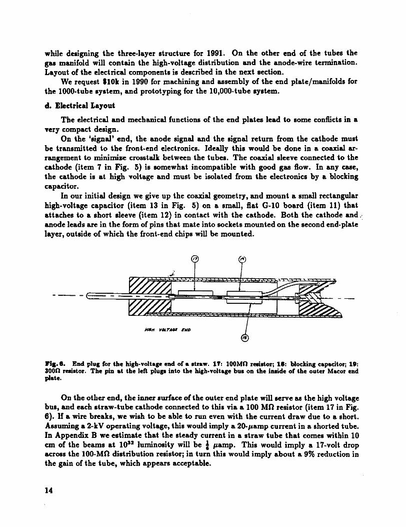
while designing the three-layerstructurefor 1991. On the other end of the tubes thegasmanifold will contain the high-voltagedistribution and the anode-wiretermination.Layoutof the electricalcomponentsis describedin the next section.
We request110k in 1990 for machiningand assemblyof the end plate/manifoldsforthe 1000-tubesystem,and prototypingfor the 10,000-tubesystem.
d. Electrical Layout
The electricaland mechanicalfunctions of the end plateslead to someconflicts in avery compactdesign.
On the ‘signal’ end, the anodesignal and the signal return from the cathodemustbe transmittedto the front-endelectronics. Ideally this would be done in a coaxial arrangementto minimize crosstalkbetweenthe tubes. The coaxial sleeveconnectedto thecathodeitem 7 in Fig. 5 is somewhatincompatiblewith good gas flow. In any case,the cathodeis at high voltageand must be isolated from the electronicsby a blockingcapacitor.
In our initial designwe give up the coaxial geometry,andmount a small rectangularhigh-voltagecapacitoritem 13 in Fig. 5 on a small, flat G-1O board item 11 thatattachesto a short sleeveitem 12 in contact with the cathode. Both the cathodeand.anodeleadsarein theform of pins that mateinto socketsmountedon the secondend-platelayer,outsideof which the front-endchips will be mounted.
Cc!
______
I
____
- -c ___?35’
__
... ‘.1 j’l.
I.
.
Nan varaz two
FIg. 0. End plug for the high-voltageend of a straw. 17: IOOMi1 resistor; 15: blocking capacitor; 19:3000 resistor. The pin at the left plugs into the high-voltage bu. on the inside of the outer Macor endplate.
On theotherend, theinnersurfaceof theouterendplate will serveasthe high voltagebus,and eachstraw-tubecathodeconnectedto this via a 100 MO resistor item 17 in Fig.6. If a wire breaks,we wish to be ableto run evenwith the currentdraw due to a short.Assuminga 2-kY operatingvoltage,this would imply a 20-pampcurrentin a shortedtube.In Appendix B weestimatethat the steadycurrentin a strawtubethat comeswithin 10cm of the beamsat 1032 luminosity will be I pamp. This would imply a 17-volt dropacrossthe 100-MO distribution resistor;in turn this would imply abouta 9% reductioninthe gain of the tube,which appearsacceptable.
14

Also at the other end of the tube,the anodewire should be terminatedin the characteristictransmission-lineimpedanceof the tube,about 300 0. This requiresa blockingcapacitoraswell. The two resistorsand the capacitorneededat this endwill be mountedon a small C-l0 boardassketchedin Fig. 6.
We will be testing the proposedlayout of the passivetube-endcomponentsin Fall1989. If crosstalkprovesto be a problemwe will explore the useof a completelycoaxialgeometry,which would requirecustomresistorsandcapacitorsmadein theform of hollowcylinders. We request15k in 1990 for the tube-endcomponentsand their assemblyforboth the 1,000-and 10,000-tubesytems.
4. Choice of ChamberGas
A review of measuredparametersof the most relevantchambergases,dimethyletherDME, Ar/CO2,or CF4/isobutane,is given in Appendix C.
a. Resolutkn
As mentionedat the end of sec. II, the operation of the detectorat ‘only’ 10"luminositypermits one to be ambitiousaboutthe resolutionof the straw-tubechambers.At this luminosity the averagetime betweeninteractionsis 100 nsec,which setsthe scalefor the acceptabledrift time without undo complicationsfrom multiple events.That is, ifwehavethefreedomto choosethe drift time in the straw-tubegas,it shouldbe about 100nsec16 nsec for 10" luminosity. Thenif the time digitization is accurateto 1 nsec andthe drift distancetube radius is 2.5 mm, eachtime bin correspondsto 25 pm in space.To achievesucha resolution, the diffusion in the gasmust be comparablysmall.
Resultsarepresentedin Appendix C for diffusion and drift velocity in variousgasesas a function of electric field strengthexpressedin termsof ky/cm, and in V/cm-Torr.We supposethe straw tubes will operateat one atmospherepressure= 760 Tort. Theelectric field strengthcanbe written
E= rlnD/
To set the scale,supposewe operateat V = 1.5 kY for a tubewith D = 4 mm andd = 20pm. Thenthe minimumelectricfield, which occursat r = D/2, is Esn = 1.42 kV/cm =
1.86 V/cm-Torr.From thefigures in Appendix C we find that for field strengthup to a few timesEnt
the drift velocity is apprxiinatelyv[cm/psecj = 0.3SEIkV/cniin DME;vcm/psec]= 0.7OEIkV/cm] in C02vlcm/psec]= 10 in CF4/isobutane80/20.
For the case that drift velocity varies linearly with electric field strength,the drifttime in from the outeredgeof a tube is
lnD/dD’t[psecl
= 8kV[kV]
15

where It is the coefficient 0.38 for DME and 0.7 for CO2. Then,for example,with D = 4mm, d = 20 pm, we find
2 = 168 nsecfor DME, usingI = 30.5 eV, Ecrjt 8.3 x io V/cm, inferredfrom Jibalyet at,23 V = 1800;2 = 141 nsec for C03 using I = 25 eV, Ecrjt 5 x 10’ V/cm which numbersarereally for P-10gas, V = 1070;2 = 20 nsecfor CF4/isobutane80/20.
But if we usea thicker anodewire with d = 80 pm and raisethe voltageto maintain thesamegain, then
2 = 85 nsecfor DME, at V = 2640;2 = 60 nsecfor CO3, at V = 1550;2 = 20 nsecfor CF4/isobutane80/20, asv is saturated.
Thus there are tubeparametersthat are well matchedto the drift velocity of bothDME andCO3 for running at 10" luminosity. The CF4/isobutanemixture couldbe quiteappropriateto running at 10" luminosity, but the electronicsmust be extremelyfast ifgood position information is to be extracted.
The dataon the diffusion coefficientspresentedin Appendix C indicatethat CO3 andAr/CF4 havesimilar diffusion an impressiveresult for the ‘fast’ gasCF4, and that bothareonly about30% worsethan DME. We estimatethat diffusion in CF4/isobutaneis notworsethan in Ar/CF4, aitfiough thereappearsto be no direct measurementto supportthis. Over a 2-mm drift distancethe longitudinal diffusion in DME is in principle onlyabout 20 pm, and about 27 pm for CO2 and for CF4/isobutane.A longitudinal diffusionin DME of 30 pm over 2-mm drift is inferred from actualmeasurementsin strawtubes.
Thus DME seemsthe best candidategas in termsof spatial resolution,especiallyifa thicker anodewire is used. Pure CO3 is also quite attractive,and considerablymorebenignthanDME.
b. Ageing
As notedin AppendixC, all of the gasesunderconsiderationhavedemonstratedfairlygood ageing- more than 1 C/cm chargedcanbecollected beforethe gain deterioratesdueto depositson theanodewire. In AppendixB we estimatethat a 1-C/cmlifetime translatesinto 6 yearsof operationat the SSC at 10" luminosity for straw tubes that comewithin10 cm of the beams.We considerthis to be acceptable,and do not proposeto makeanyageingstudiesin the immediatefuture.
c. ChemicalAggressivity
Dimethlyether is reported by some to causedamageto the straw materials. SeeAppendix C. The story here is not very consistent. On the West Coast lots of troubleoccurred,but H. Kagan private communicationreportsgood successin using DME inlEO runs. Most disturbingis theclaim that DME eatsMACOR, themachinableceramicthat we might use for the chamberendplates.We must investigatethis immediately.
Apparentlyoneshouldhaveagassystemwith no plasticparts,including thoseplasticsthat are supposedlycorrosion resistant. Also, the two ends of the straws should notbe mechanicallyconstrainedto a fixed separationas was the casein early West-Coastdesigns.
16

There are also reports of batch-to-batchvariation in the purity of commercialdimethylether,with freon contaminantsbeingespeciallyharmful. S. Majewski privatecommunicationreportsthat good-purityDME cannow beobtaineddirectly from DuPont.
Since dimethyletherhasthe best all-around performanceof any potential chambergas,it is worthwhile to determinewhetherwe can survive the aggressivityproblem. Wewill needa gaschromatograph,suchas the SRI Model 8610-003$4k that interfacestoan IBM PC, to monitor the purity of the deliveredDME. Also, we must buy the most‘corrosion resistance’regulators,valves,flowmeters,etc.,that exist. We estimatetheextracost to build a DME gassystem,comparedto that for a benigngas,as $tk, and requestfunding for this in the 1990 budget.
d. Gas-DistributionSystem
We needto constructa good-qualitygas-distributionsystemin the nearfuture, anddesireto adopt a standardsuitable for eventualrunning in a collider environment. Thiscertainlymeansuseof mass-flowcontrollers,suchas MathesonModel 8219 $2600 for atwo-gasmixer, and electronicratherthanmechanicalflowmetersone eachof Matheson8202-1413and 8102-1413per gastype, totaling $2300 for two gases.We needtwo additional massflownieters Matheson8111, $400 eachas well as various regulators,valvesandplumbing. We will needa gain-monitoringchamber,and a good leak detectorsuchasthe MathesonModel 8065 $ 1300.
We request$8k for the gas-distributionsystemasidefrom the Uk requestedabovefor specialhandlingof DME.
e. HeatLoad Due to Ionization
In Appendix B we also estimate that the heat dissipation due to the electron/ioncurrentsin a straw tube that comeswithin 10 cm of the beamsat 1032 luminosity is fmWatt. The gasflow must be adequateto cool this beatload.
A very nice analysisof this problemwasgiven by J. Kadyk and S. Whitaker at theVancouverSSCTracking Workshoplast July. They concludedthat for a one mWatt heatload in CO2 gas,the gasmust flow at 2 cm/secin the tube to keep the gain constantto 5%. This wasbasedon a model of the gasgain C as a function of temperaturethatsuggests
ATC 5T
The Diethornmodel,t however,suggeststhat
AGATGT
This disparity shouldbe resolved,and likely will requiredirect measurementof the temperaturedependance.
If we accpet the more pessimistic temperaturedependance,our mWatt heat loadwould requirea flow of 0.67 cm/secin CO3.
The heatcapacityper mole of DME is aboutthreetimes that of CO3, soif DME canbe used,the estimatedflow velocity is only 0.22 cm/sec. For a 2-m-long strawthe timeper volume changewould thenbe 900 sec for DME and 300 sec for CO,.
17

f. Heat Load of the Front-EndElectronics
We anticipatethat the front-endelectronicsmust be mountedinside thechamber-gasmanifolds. Thereare two feedthroughsper straw in the circuit board that supportsthefront-endelectronics,and it may be askingtoo muchthat theseall be gas tight.
The heat load of the AT&T Bipolar front-endchip is about 25 mWatt per channel,far in excessof that consideredin the previoussubsection.Hence we cannotexpect theflow of the chambergasto be sufficient to cool the electronics.
Rather,the gasmanifold on the ‘signal’ endof the strawsshould include a high-raterecirculatingsystemthat primarily cools the electronics,and incidentally bleedsa smallfraction of the gasinto the straw-tubes.We do not requestfunds for this part of the gassystemin 1990, but will do sofor 1991.
g. Pressurization
As hasbeenmentionedin passingabove,we envisageoperatingthe straw tubesatonly slightly aboveatmosphericpressure.While the spatial resolutionobtainablein a gasvaries, in principle, as1//, the low-massgas manifolds are unlikely to be leak tightunderpressure.
h Lorentz Angle
The strawsare in a magneticfield that is orientedalong the anodewire. HencetheLorentz force causesa deflectionof the drift of an electronby
tanO= v/cB =
= 0.lkB[Tesla],
for gasesin which the drift velocity obeysv = kE, and for which k is measuredas insection4-a above. This indicatesthat the Lorentz anglein a 1 Teslafield would be 2° forDME and 4° for CO2.
Theseanglesare so small as to requireno correction,anotheradvantageof a ‘slow’gas.
5. Front-End Electronics
The front-end electronicsfor the straw-tubesystemare to be basedon the ongoingwork of the U. Penngroup,’°’3 who havebeenexploringASIC’s for SSCapplicationsforseveralyears.Their designof a fast Bipolar preamp/shaper/discriis very well suitedto bethe front-endchip, and the Penn/Leuvendesign’°’13 of a CMOS TVC chip is a prototypeof the digital processingthat should also be locatedon the strawends.
Sample quantitiesof the Bipolar preampare now available,as implementedin anAT&T semi-customprocess.Testsof this chip show a pulsewidth of 10 nsec,and 1200electronnoiseasmeasuredby theshapeof a discriminatorcurveF.M. Newcomer,privatecommunication.
Some50-100of thesepreamp/shaperchips will be availablefor use in test setupsinFall 1989.
18

a. CustomRun ofthe AT&T Bipolar Chip
A natural step in the developmentof the front-end electronicsis a full-custom runof the AT&T chip in which a disriminator is included along with the preamp/shaperofthe samplechips. In a full-custom run the layout canbe arrangedso that four channelsare combinedin a single die. Funding of $50k for the first full-custom AT&T run hasbeenrequestedaspart of theU. PennFront-EndSubsystemproposal.12This run shouldproduce1000-2000chips on 3-5 wafers.
It is not guaranteedthat the output of the first full-custom run will be satisfactoryfor actual use on detectors.Also, this first run will usecertaindesignparametersinputimpedance,tail-cancellationtime, amplifier gain not necessarilymatchedto the performanceof the strawtubesof this proposal.We feel it prudentto anticipatetheneedfor asecondrun to correctanyprocessingerrorsin thefirst run, andto makesmall adjustmentsin designparameters.
The secondAT&T bipolar run should be made no later than Spring 1990 to insureavailability of chips towardsthe end of the 1990 Fermilabfixed-target run. We request$sOk in 1990 for this. The chips shouldbe mountedin suitablecarriersat the foundry aspart of the cost of the productionrun.
For the 1991 phaseof this proposala new bipolar runwill be neededto bring thechipcount to 10,000or more,but we do not requestfunds for this at present.
b. TestingandMountingof the Chips
As productionquantitiesof thousandsof chips becomeavailablewe must test themand mount them on the straw-tubedetectors.Thenthey must be testedin a setupto beconstructed.We haverecently purchasedan Ortec 419 pulserthat will be useful for this.In addition we would like to purchasea digital patterngenerator$2k that residesin anIBM PC-clone,and a fast oscilloscopeTektronix 24658,$6k.
The chips arethento be mountedon a printed-circuit boardthat will be attachedtothe gasmanifolds of the straw-tubemodules. This board will be designedat Princetonand madelocally.
We request*15k in 1990 for the testinstrumentationand the pc-boardfabrication.
0. WestinghouseSIMOX Process
The Bipolar preaxnp/shaper/discriis to be followed by a TDC chip, discussedfurtherin sec. 7 below, also locatedon the chambers. The best apparenttechnologyfor thisdigital chip is CMOS. Civen the eventualexistenceof the two typesof chips,they mustbe bondedtogetherto form a kind of hybrid for useon a detector.
It is worth exploring technologiesthat will permit the fast preampand the digitalsectionto be implementedin the samesilicon process. In conjunctionwith a SSC PixelDetectorSubsystemProposal’4 we havelearnedthat HughesAircraft hasa ‘Bi-CMOS’processthat might be suitable for the presentapplication. Discussionshavenot evolvedto the stageof a definite proposal,but opportunity for suchshould readily occur in thenext monthsif that proposalis approved.
19

Another exciting opportunity is the so-called SIMOX processSilicon isolated byIMplanted OXygen of Westinghouse.In this a high-resistivitysilicon wafer high enoughfor the substrateto be a particledetector! is bombaredwith oxygenions to form anoxidelayerabout 2000 A thick approximately1000 A below the walersurface. The devicesareimplanted on this thin layer, and can be extremely fast becauseof the small numberofelectron-holepairs involved in the currentpaths.This processwasdesignedfor gigaHertzRF applications,but hasbeensomewhatunderutilizedin the commercialmarket to date.The device layersare implementedin a CMOS technologyand hencewill be ratherlow-poweraswell as very fast.
We proposeto makea test of the suitability of this processfor SSC front-end electronics by producinga preamp/shaperthat is functionally equivalentto the existing U.Penn. Bipolar chip. The designwork as well as the foundry runswould be performedatWestinghouse,and testingdoneat Princeton.
a. The SIMOX Approachto IncreasingIC Functionality
Originally SIMOX wasviewed asa meansof providing radiation-resistantdigital circuits for military and spaceapplications. Becauseit allows higher circuit density thanconventionaljunction-isolationmethods,SIMOX is beingconsideredasa majornew thrustfor commercialdigital IC applicationsaswell. Westinghouseis in the processoffurtherextending the applicationof SIMOX by pursuingdevelopmentsusing high-resistivitysiliconwafersas the startingsubstrates.This shouldprovidea Si analogto GaAs linear circuitryon semi-insulatingGaAs substrates,and allow Si FETs to be consideredfor applicationsat muchhigher frequenciesto 5 GHz thanpreviously consideredpossible.This possibility is providedby the elimination of substrateparasiticeffects low-to-moderateshuntingresistancesandmoderate-to-highjunction capacitanceswith useof substratesof higherresistivity 200 to > 1,000 ohm-cm,dependingon application than conventionallyusedfor IC applications10 ohm-cmor less.
- In addition, the useof SIMOX, in the limit with active device-layerthicknessesbelow150 nm, provideshigher MOSFET metal-oxide-siliconfield effect transistorperformancethan doesbulk isolation. Furthermore,the use of very shoft MOSFET channelsbelowabout0.7 ym to increasedevicespeedoperatingfrequencyis not penalizedby undesirablefield effect feedbackasit is with bulk isolation methods.
For thesereasons,the Westinghouseapproachwill extendthe advantagesof SIMOXfor digital circuit applicationsto high-frequencylinear-circuituses,andprovide theopportunity to integratehigh-performancelinear circuitry with high-density,high-speeddigitalcircuits.
Theseadvantagesaresummarizedbelow in outline form:
o Limited JunctionVolume* Transient-radiationhardness* SEU immunity* Low leakage/powerdissipation* Low leakageat high temperature
o Fully DepletedChannels
20

* Low junction fields . high voltage* High transconductance high current,frequency,and speed* Smallerchannellengths* higherperformance,density
o Buried-OxideInsulator
* Radiationhard Total dose* High-temperaturecapability* Compatiblewith high-quality silicon
o High-resistivity substrate
* Reducedshunt resistance,capacitanceparasitics* high-frequencylinear capability
* SupportsMicrostrip interconnectlines
b. WestinghouseCapability
As far as the technology to implement this capability is concerned,Westinghousepossessesexpertisein threetechnicalareasthat combine synergisticallyfor the extendedSIMOX effort.
The first is SIMOX itself. This is a materialstechnology that hasbeen developedto serve the needsof the radiation-hardsignal-processingintegratedcircuit community.Westinghousehaspursuedthis topic for severalyearsto developa successortechnologytoSilicon-on-Sapphirefor rad-hardmemories. Good working relationshipshavebeenestablished with IBIS, the primary SIMOX vendor,as well aswith Spire, a secondsource,andwith EatonCorp., developerof the commercialimplantationequipment.
Thesecondnecessarytechnicalfacility is ultra-highresistivity silicon startingmaterial.Westinghousehasa unique float-zonesilicon-growth facility that supportspower-devicematerialsdevelopmentand is recognizedas a world leaderin this technology.
Thethird essentialfacility is anoperationalmicrolithographycapability for fabricatingsub-microngatesfor fast FETs. The CambridgeElectronBeamMicrofabricatoris on lineat the Scienceand TechnologyCenter. It hasbeen usedto produceGaAs power FETswith gatelengthsand perihpheriesof 0.05 and 2000 pm, respectively.Also polycrystallinesilicon gatestructuresof 0.25-pmlength havebeenproduced.
Recentresultsshow that MOS field-effect translatorsfabricatedwith O.25-tsmgatelengthson bulk silicon with very thin gateoxidesabout 36 A exhibit transconductancesof 680 mS/mm. This is near the valuesthat can be achievedwith GaAs High ElectronMobility Transistors. To further enhancethe silicon FET performance,a fully depletedtransistorarchitecturethat is feasiblewith SIMOX technologyis used. This eliminatescoupling and lossesthat normally characterizeordinary bulk MOSFETs.
Other technicalopportunitiesof SIMOX on semi-insulatingsilicon includeintegrationof fast logic and memoryon the samechip that performs an analogfunction and, veryimportantly, the provisiionof complementaryp- andn-channeldevicesfor high-efficiencypoweramplification. This complementarycircuitry is not availablein GaAstechnologybutis anestablishedfeatureof modernsilicon technology.Tables1 and 2 summarizethe statusof processingand devicework on an internalWestinghouseprogramwhich is applying thesemi-insulatingSIMOX approachto integrateanaloganddigital functionsfor radaruse.
21

Table 1. Statusof Semi-InsulatingSIMOX Processing.
Verification Effort
* 1/4 pm EB-definedpolysilicon lines* 0.6 pm optically-definedgatepatterns* Low-loss 50 fi microstrip lines on high-resistivity Si* High-resistivity retention
- Rapid thermal processing- Furnaceprocessing:ambienttemperature- SIMOX: high-T Anneal
DevelopmentEffort
* Thin oxidegrowth matrix 30-100AWetDryPostoxidation anneal
* Salicide self-alignedsilicides matrix* Gettering* Ti-W resistors
Planned
Table 2. Device Status
Design Issues
- FET ParameterExtractionTest Vehicle PETV- Modelling- PIN diode PETV- IntegratedSPDT microwaveswitch
Device Processing
- RET PETV on:Normal 20 fl-cm SiHigh-resistivity FZ SiSemi-insulatingSIMOX
- PIN diodePETV- IntegratedPIN diode SPDT switch- Passiveattenuatornetwork.- Attenuator/switchintegration
* Planned
22

c Budget
The following is an estimateof the effort at the WestinghouseScienceandTechnologyCenter,Pittsburgh,Pennsylvaniato translatea shaping-amplifierfunction from a demon
stratedbulk Bipolar form into one using semi-insulatingSIMOX with complementary-CMOS circuitry.
Task Estimated SubtotalCost
Circuit simulation $50kCircuit layout 20kTesting 25k
195k
Deviceparameterextraction 20kNoiseperformanceoptimization 20kFabrication 35k
75k
Total 1170k
6. TDC Development
While weintendtu useLeCroycamacTDC’s to analysethesignalsfrom the 1000-tubesystemin 1990, it is not practicalnor pertinent to use this approachfor later straw-tubesystems,beginningwith the 10,000-tubesystemin 1991. A VLSI TDC shouldbedesignedthat resideson the detector, and eventually includes analog storageduring a suitabletrigger-delayinterval. -
a. The Penn/LeuvenDesign
As mentioned above, such a chip has been designed by the Penn/Leuvencollaboration’°"3 althoughwith slightly different parametersthan would be optimal fora straw-tubesystemoperatingat 1032 luminosity. This work hasbeendone primarily atLeuven. In thesedesigns the time of arrival relative to a start pulse is convertedto avoltagethat is later digitized in an ADC. As such,this chip is often referredto as a TVCratherthana TDC.
The Penngroup is now preparing’2to implementa designthat is closerto the needsof the 1991 tracking systemof the presentproposal.The latterare:
0.5-nsectime resolution;Analog storagefor up to 5 psec;Time digitization of 8 bits = 128 nsec.
We makeno requestfor funds in 1990 for this project, as it is coveredin the Pennproposal,but will closelyfollow their progress.We anticipatethe needfor funding in 1991for productionsruns to yield in excessof 10,000TDC chips.
23

b. The KEK TMC Chip
An interestingalternativeto the Penn TVC chip is being developedat KEK.’5 Thischip is a true TDC in that the time of arrival of the signal is directly digitized in 1nsecintervals. However, the referenceclock runsat only 60 MHz andthe input signal ismultiplexed 16-fold.
Samplequantitiesof this chip are now available,and we havea rather tentativearrangementto include someof thesein the Fermilabfixed-target run in 1990. We do notrequestany funds for this at present.
8. Manufacturing Feasibility Study
The task of constructiona straw-tubechambersystemof 250,000 or more tubes islikely beyondthe resourcesof a university group. Eachtuberequiresseveralstepsof handlabor, and thereareonly 120,000 minutesin a standardwork year. We expect the large-scaleproduction to be performedby industry and wish to explore arrangmentsto thisend.
In 1990 the WestinghouseScienceand TechnologyCenterproposesto initiate amanufacturingfeasibility studyin basedon the straw-tubedesigndescribedabove.A Statementof Work for this study follows or put in an Appendix?
a. Statementof work
The WestinghouseElectric Corporationproposesa 12-monthprogramto perform thepreliminary mechanicaldesign and analysisof a straw-tubetracking subsystemfor thesuperconductingsupercolliderSSC. The work will be carried out at the WestinghouseScience& Technology CenterSTC in Pittsburgh, Pa. Upon completion of the proposedprogram,necessarydetail andassemblydrawingsfor manufactureand testingof thetracking-modulecomponentswil be deliveredto PrincetonUniversity.
Theprogramis divided into two specific areasof performance:
* Mechanicaldesign* Manufacturability
Thesetwo areashavebeendivided into five tasks. Eachtask is describedbelow
Task 1. Straw-TubeTrackingSubsystemDefinition and Specification
In Task 1, WestinghouseSTC will work with Princeton University to specify thefunctional designrequirementsfor the tracker. Physicalconstraints,suchas size, weight,length, and detectorgeometry,will be identified as well as electrical leads and coolingrequirements.This effort will requiremost of thefirst yearof the program.This length oftime will be requiredin order to makespecificationmodificationsasthe conceptprogressesover the first year.
Task 2. MechanicalDesignand Analysis
In Task 2, the preliminarydesignof the trackerassemblywill be performed.Conceptsproposedby the working group of STC and PrincetonUniversity will be reviewed and
24

evaluated.The final selectedconceptwill be analyzedfor .. .y to ensuresufficient stability and rigidity sothat alignmentrequiremen .: ‘ ied over thedesign life of the device. Routing and connectionsof powe . strumentation cabling and hoseswill be conceptualized.Materials select o. ction of thedetectorwill be basedon input from PrincetonUniversity.
Task 3. FabricationDrawingsand Interftces
Layoutdrawingsof conceptsproposedandstudiedin Task2 ci ed. Conceptdrawingsof the selectedstraw-tubetrackerfor a 10,000-strawtii: onfigurationwill bepreparedin sufficient detail to obtaincostingandscheduling a. Assemblydrawingswill be developedasnecessaryto assistin the fabrication & i.. y procedureas well as interfaceswith adjacentsubsystems.
Task 4. Fabrication/AssemblyProcedures
The purposeof this task is to specify in sufficientassemblyproceduresrequiredof the conceptselected.items as the following:
* Strawtubemodulemounting procedure -* Strawtubemoduleassemblyprocedure* Structuralsupportfabricationmethod* Module assemblysequence* Electricalcable routing procedure* Cooling hoserouting procedure
Theseprocedureswill be preparedin a form to matchthe concep4 and costingestimaterequirementsfor constructionof a device.
Task 5. ProgramManagement
The program-managementtask consistsof the preparationof reports, esignreviews,general meetings,and cost reportingto the overall programmanager. V...- ‘nates of theWestinghouseeffort arebasedon the following activities:
* Monthly progressand cost letter reportsfor 12 months* Group meetingsat PrinetonUniversity every 6 weeks* Yearly report to DOE describingtechnicalprogress
detail the fab :ocessesandTheseprocedtebw’ include such
25

b. BudgetSummary
A. Material/EquipmentB. Labor
1. Engineering2,276 hours $69,0202. Support 480 hours $10,3423. Total Labor 2,756 hours $79,362
C. Overheadvariousratesused $95,552D. Other
4. Consultants5. Computer6. Subcontractors7. Other $4,392
E. IWRF. Total Direct Costs $179,306C G&A 16.870% $30,249H. P. 0. T. CostsI. COC - STC9.79%of $83k $7,775J. COC - CORP 0.241%of F $432K. Total Costs $217,762L.Fee -
M. Total CostsSt Fee $217,762
9. Simulation of PhysicsPerformance
A major effort will be made at Princetonduring 1990 to developa full GEANTsimulationof thestraw-tubesystem,andto write ananalysispackagethat performspatternrecognitionand track fitting. This work is in collaborationwith physicistsfrom Fermilaband U. Floridawho havenot signedthepresentproposalfor organizationalreasons.Figures1, 3 and 4 arefrom this effort.
A requestof $25k for hardwareimprovementsto our existing computingfacilities wassubmittedas part of Princeton’s1989 GenericDetectorDevelopmentproposalrenewal. Iinterpreta recenttelephoneconversationwith Tom Dombeckthat this $25k wasapproved.If not, we requestthe $25k aspart of the presentproposal.
With funds from Princeton’s 1988 GenericDetectorDevelopmentcontract we havepurchaseda DEC VAXstation 3100 and DECstation3100. The latter will give us entryinto the UNIX world while maintaininga VMS connection.In 1990 we wish to expandourcomputingpowerto about 50 MIPS, andanticipatepurchasinga workstationsbasedonthe Intel 80860processor.This direction is suggestedby our proposalto participatewithIntel in the developmentof a largeprocessorfarm for online computingat the SSC.15
We haveestimatedthat a ‘full’ simulationof the tracking in an SSC detectorbasedon GEANT and having the ability to simulateio eventsper week will require250-500MIPS of CPU power. Evenwith our proposedexpansionto 50 MIPS in 1990 we will onlybe able to performsimulationsthat takemajor shortcuts. Of course, this is exactly theway to start. But we anticipatethe needfor continuedupgradesin computingpowerin
26

the following years. Fortunatelythe trend in price/performanceof RISC processorsis sofavorable that constantdollars will purchasenearly exponentialincreasesin CPU powerover severalyears.
9. Test Program
a. Gain Studies
We are currently testing a small straw-tubechamberwith sevenstrawsand severaldifferent anode-wirediameters. A set of test electronicsfor a single channelhas beenpurchasedfrom Ortec for this. The emphasishereis studiesof the gain in the strawtubefor variousgases.
In the presentproposalwe request$4k for gasesto be testedin 1990: DME andisobutaneapproach$500 per bottle, and CF4 is $2k per bottle. We will likely needtoorder DME from morethanone vendorto examinethe deliverablepurity.
b. ResolutionStudies
In Fall 1989/Winter1990 we plan to constructa chamberwith 64 strawtubes, asshown in Fig. 2, to perform resolution studies using cosmic rays. A relatively largenumberof channelswill be usefulas the ratesare low, andwill providea prototypefor the1000-tubesystemto be built in Spring 1990.
The front-end chips for this test will be the sample quantities of the Bipolarpreamp/shapernow in exisitenceno discriminator. Discriminators,ADC’s, TDC’s, andtrigger logic will be borrowedfrom PREPat Fermilab. The straw tubesand end plugsneededwill be taken from suppliesfor the 1000-tubedevelopmentdescribedabove. Werequest$5k for miscellaneoussupplies,Macor end plates,mountingfixtures, two triggerscintillation counters,etc.,and $5k for an 80836 IBM PC-clonecomputersystemto controlthe test,for a total of $iok in 1990.
c. PulsedX-Ray TestFacilty
We desirea reasonablyquick methodof measuringthe time-to-distancerelation inthe straw tubes that doesnot requirea high-energycharged-particletest beam. As thestraw-tubesare opaqueand sealed,it is not possibleto use a laser to simulateparticletracks. This leavesx-raysas themain candidate.The problemhereis that typically thereis no timing signalassociatedwith an x-ray source,so thetime-to-distancerelationcannotbe reconstructed.
We have openeddiscussionswith Kevex Phillip Heskette,408-438-5940towardspurchaseof a custom pulsed x-ray source,and request$25k in 1990 for this. Such asourcewould bean extremelyvaluableaddition to the diagnostictools availablefor strawchambers,and could be installed in a collider experimentitself to provide continuallyupdatedtiming calibrations.
27

d. Fixed-TargetTest
We have mentionedseveraltimes our plansto test a set of some 1000 straw tubesat the M-Test line at Fermilab in 1990. The straw tubesand electronicsfor this are partof aboverequests. The test will also include a set of silicon strip detectors. A primarygoal is to demonstratea tracking arrangementwith a few silicon planesdoseto the vertexfollowed by a set of strawtubeswith longer lever arm.
Herewe request*25k in 1990to coverconstructionof standsfor the straws$5k, andfor travel to and operatingexpensesat Fermilab$lOk eachfor lIT and Princeton. Aswell as involving physicistsand studentsin suchtests, severaltechicianswill participatein the setupphaseat Fermilab, which requiressufficient operatingfunds.
28

Appendix A. RadiationLengthsof the Straw-Tubes
We calculatethe radiationlengthsof severalvariationson straw-tubeconstruction.Let
D = strawdiameter.T = thicknessof wall materialR = anodewire radius
Then the total areaof wall material is irDT, and the width of the strawis D, so theeffectivethicknessof wall material,as seenby a passingpartide, is
twall = ,rT.
Similarly, the areaof the anodewire is rR2, and we distribute this as an effectivethicknessoverdiameter11, so
,rR2twire
=
The ‘original’ strawdesignhas11=4mm;Tmylar = 27.5 pm, so imylar = 86.4 pm;TAl = 0.1 pm, soiAl = 0.31 pin;R = 10 pm, so tW = 0.0078pm.
A radiationlength in variousmaterialsisXomylar = 287,000pm;X0Al = 89,000 pm;XoW = 3,500 pm;XoCu = 14,300pm.
So the numberof radiationlengthsper ‘original’ straw isxmylar = 0.000301;zAl = 0.000003;zW = 0.000022;xtotal = 0.000326 radiationlengths.
We now consider3 changesin the straws.
1. Increasethe aluminumlayer to 0.5 pm to reducethe resistanceof the cathode.tAl = 3.14 pm, zAl = 0.000017,=- ztotal = 0.000340.
2. Replacethe 0.5 pm of Al by 0.3 pm of copper. This gives the samecathoderesistance.However,copperhasthe advantagethat its oxide is conducting,while aluminumoxide isnot. This may alleviatecertainhigh voltagebreakdownproblems.
tCu = 0.94 pm,zCu = 0.000066,* ztotal = 0.000389.
3. Use the coppercathode,and increasethe anodewire radius to 40 pm. The increaseinwire radiusfights the wire instability, anddecreasesthe probability of local sparkingasthe curvatureof the anodeis less.
29

tW = 1.26 pm, zW = 0,000359,. ztotal = 0.000726.
Is this bad? The wire now hasthe samenumberof radiationlengthsasthe mylar,so it’s not out of line. 100 strawsnow have8% of a radiation length. The air betweenthe strawsover 1 m contributesan additional 1/3% radiation length. The straw systemexcludingend plugs! will casuea Pr kick of 4 MeV/c, or 0.4%at I GeV. This should nobe a seriouslimitation.
Appendix B. Straw-TubeLifetime
Herewe makean estimateof straw-tubelifetime at the SSC.We concludethat strawsextendingto within 10-cm radiusof the beamwould haveabouta 6-yearlifetime at 1032
cm’2sec’luminosity. This estimateis similar to a previousanalysisby B.. Kadel."We infer from studiesof gas counterlifetime Appendix C that they survive until
about 1 Coulomb of chargehasbeen collectedper cm along the anodewire. They diemainly dueto depositionof a dielectriccoatingon the anodewire from molecularfragmentscreatedby the ionization.
We estimatethe chargecollectedby a straw-tubecounterat the SSC:* In one "SSC year" thereare 10 sec.
* At 10" luminosity thereare 10’ interactionsper sec.
* In one interactionthereare 100 tracks.
÷ So far we havea total of 1016 tracksper SSCyear.
Now supposethe strawsextend to within 10 cm of the beam. We considera 1 cmlengthof strawat this radius10 cm as the portion having the highestradiation dose..
Takea strawdiameteras5 mm, which the occupies1/120 of the azimuthat 10 cm.The extent of this piece of strawin pseudorapidityq is estimatedfrom the relation
dq = dO/B. So for a straw locatedat less than 300 cm from the intersectalong z, weinfer that di7 C 1/10. Since the tracksarespreadover 10 units of rapidity, the fractionalacceptanceof the hottest 1 cm of strawis only 1/100 in rapidity.
* The combinedacceptancein rapidity and azimuthfor our 1-cm pieceof strawis onlyio-.
+ That is, 1016 tracks/year x io- = 10" tracksperyear in the hottest 1 cm of a strawat 10-cmradius at 10" luminosity.Supposethe averagetrack length in a strawis 4 mm, and thereare 100 electrons
liberatedper cm by a trackcomparedto only about40 percm for argongas. That is, 40electronsper track liberatedin the straw. [This estimateis somewhatdependenton theorientationof the straw. In BCD wherethe strawsarelargely transverseto the beamit isok. In a solenoidgeometrythe track length might be more like 11 mm over a 1 cm lengthof strawat small angles.Seethe final sentence.1
* The chamberis run with gasgain around2.5 x i0, soabout io electronsreachtheanodeper track.
30

+ Finally, we arrive at an estimateof 1012 tracks x106 electronsper track = 1018
electrons= I Coulomb collectedin one SSC year in the hottest 1 cm of strawat 10cm radiusat 1032 luminosity.
* This pieceof strawwould thenhavea lifetime of approximately6 SSCyearsusing thecriterion of 1 C/cm collectedchargebefore chamberdeterioration.
To havea 10-yearlifetime at 10" luminosity, the strawshould be at io/Th7i = 41-cm radius,accordingto ourestimate.But if the strawis orientedparallel to the beams,itshouldbe y’Ti7 = 1.66 timesfartherout, namely68 cm.
It is useful to extract an estimateof the steadycurrentin a straw-tubechamberfromthe above.Dividing thechargeper yearby 10 sec weobtain a currentof pampdue thehottest 1 cm of a strawat 10 cm from the beams.Integratingover thelengthof the straw,orientedperpendicularto the beams,we should multiply by 10 to get the total current:
pamp at 1032 luminosity.We can also estimatethe heatdissipationin the gasitself by multiplying the current
and the chambervoltage. Namely I pamp x 2000 volts = I mWatt. While not negligible, this is small comparedto theexpectedpowerdissipation in the front-endelectronics.
31

AppendixC. A Surveyof GasMixtures
We review severalgasmixtures that have beenusedin strawtubes. Basedupon thepresentknowledge,the threemain candidatesfor the gasto beusedin straw-tubedetectorsareDME dimethylether,Ar/C02, and CF4. The advantagesanddisadvantagesfor thesecandidatesare compared.
1. Dimethylether DME
a. Generalpropertiesof DME [CH3301TableI.
Molecular weight 46.07Density 25°C 1.918 g/l
Relativedensityair = 1 1.621Critical temperature 400°K
Vapor pressureat 20°C 52 atmFlammability limit in air 3.4-18%in volume
Radiationlength 25°C, 1 atm 4.5 x 10 Xo/m
b. Drift velocity
IOUI I
-Do
0000
E S
IOo_ *.* -
oArcO2a44_.1 *Thisrk
op
E/p volt/cm-tort
Fig.?. Drift velocity of DME.
32

I-
100
so
ONE tat.
a Lii IV/caTonl
. ..237 tV/c..torrl
* .315 V/ca Ton
Hff.0 05 ID 15
a
Iv k_Ui
I.. . .... .
ONE 2at.
fans iv,ca.Ter b
5T0 0.5 tO IS ., a.I#2
100
S.
elf LI it. .
..I.3ft’/ca-t.sr .
...1...,1..T1.... tS Ii IS 4,
Spatial resolution as a function of distance"2 trainmesh in DME. respectively at 1 atm. 2 atm. 2.1 atm. Wecombine all the wires together. and assumingthe same relationship we cakulate avenge and urost We have divided thedistance into Four bins: 1-7.5 mm. 73-IS mm. IS-US mm.and 223-30 mm.
Fig. S.
a
100
So
II Th
. TSsveric---Pr.ar,f,5 *
. atroar,t.3
+rf4A
I 2 3 & C/p V/ca.Te,
Schaviourotheskpeofthefltsinflgs.ab.flisin fact a measurement of the diffusion coefficient. Dashed lineand triangle points come respectively front ref. 5J p. 225 aidref. 3. In both cases, the data have been normalized to owpoint at L/p - 2.37V/cin.TonL In addition,the slope of thedataatL/p-l.75 V4cm.Torrp-2 atmhasbeenmuhi.pIiedbyafacsorofv touakeintoaccounttheincttaseofafacto. of 2 in pressure.
Fig. S.
aS
S
1v lca"I
Spatial resolutionas a functionof distance"2frommesh in Ar/CO2 at I atm. for three values of the dnA nelLFitted curves are apin straigltt lines. Notice that the ilOP0
the fits an vety nearly the same, indicating constancy of tile
diffusion coefficients as a function of drift field. Suclt sat
sicC of the diffusion coefficient is consistent with known
Fig. 10.
33
afl7%ICO12&% &.!!
apt? IV/catattl
ai& tvtc..toni
4. 2.1 V/cater
0

c. SpatialResolution
* The prototypetest of the MARK-3 vertexdetector" showed:DME @ 1 atm. yielded spatialresolution 35 pm;Ar/C2H6 © 4 atm. yieldedspatial resolution 30 pm.
* F. Villa’9 measuredthe spatialresolutionof DME:Drift velocity = 3.6 pm/nsec,o,. = 5.4 us a’, = 16 pm 0 1 atm.
* M. Basile et aL:2° see Fig. 8-9. For comparison,the spatial resolution of Ar/CO276/24 is also shownin Fig. 10.
d. ChemicalAggresivity Tests
* MARK-3 claims’5 DME adverselyaffectsMylar and flerlin.
* C. Ban et al.2’ put severalspecimensin DME gasfor a month. They found theweightof all specimenshad goneup at the endof the test. Signs of damagewerefound onthe surfaceof Plexiglas, Stesalit and scintillator. Epoxy, Mylar, Teflon, C-b, PVC,and carbonfiber seemedin good condition.
* M. Gibaly et al.5 claim:
Thesematerialshad adversereactionswith DME:Teflon - inducedelectronattachmentby poisoningthe gas.Class-bondedMica endcaps- producedflakes on the wire surfaceand causedquick damage.Macor - inducedwire damage.
The materialsfound compatiblewith DME were:Stainlesssteel,Monel gastubing, Nylon 11 gastubing, brass,Derlin chamberendcaps,Mylar with Sn02 coating,Ton-sealepoxy,andKalrez 0-ring.
e. Ageing Effects
* C. Ban ci al.2’ have done ageingtestsusing Kalrez DuPont 0-rings ‘guaranteed’resistantto ethers,Cu tubing, and H.V. wire insulatedwith Teflon. After collecting1 C/cm, the chamberhad neither a changein the current drawn by the wire, norreportedly in its gain. But depositswerefound on the entirelengthof the wire suchthat the diameterhad increasedfrom 20 pm to 40 pm!
* M. Jibaly et a!.22 usedgold-platedwires with "dirty" DME and found stable theoperationof their chamberup to 0.39 C/cm, while "pure" DME was good up to 1.0C/cm. SeeTable II for an analysisof the contaminentsin thesegases,and Table IIIfor details of the ageing tests. Resistivewires exhibited quick damageand the wirecurrentdroppeddown very fast. Nylon tubing looks safe, but Teflon is bad.
Freon-il [CCI3FJ in DME was the main causeof wire damage. Useof a Nanochemgaspurifier drasticallyreducedthe Freoncontentin DME.
* S. Majewski" claims that the ageingof DME is exellent,andholds one of the worldrecordsof endurance.
34

Table II.
Impurity levels of different contaminantsin dimethyl ether as determinedwith gas chromatography utilizing electron capture and flame ionizationdetectors.
I DUE GradesContaminant I
"Dirty" "Pure" "Purified"
neon-li 0.2 ppm 10 ppb Si ppb 150 ppb
Treon-12 45 ppm 1 ppm Trace’ 160 ppb
Preon-22 870 ppm <15 ppm <15 ppm Not checked
freon-in Trace* Trace’ Ho Trace** trace’
Methane 30 ppm 100 ppm 40 ppm Not Checked
Ethylene 15 ppm 50 ppm Trace Not Checked
Pnopylene 120 ppm *20 ppm 40 ppm Not Checked
Isobutane 290 ppm 10 ppm 245 ppm Not Checked
‘Tracea Chromatographicpeakwas too small to be integrated."No Trace * No peak wasvisible. . --
Table III.
Irradiation doserate 0 and relative currentgaindrop R for different wires.
Wire Type
DICE Grades
"Dirty" "Pure" ‘Purified"
Q R Q R Q R
35 pm Nicotin 0.006 11000 0.01 10000 - -
25 pm stabloha 0.02 5000 - 0.04 500
SOpaSS - - 0.10 NC - -
35 pm ES . 0.67 30 0.38 NC 0.80 NC
2Spaku/W 1.2 NC 0.90 NC
3ogsmku/W - - - 1.0 NC
SOpaAu/W - - 0.1 NC 0.1 NC
100 pmku/W 1.0, NC - - 0.4 NC
50 pm Au/Mo 0.4 NC 0.07 NC - -
o * charge + unit length,C/cm; R * %currentdrop + 0. ctC/cmy’NC * No change in current observed.
35

£ Gas Purity
e The purity of the gasusedby C. Bari ci at":
Table IV.
Manufacturer Purity% Contaminant
Fluka 99.2 0.8% Alkane, 0.001% methyl alcohol0.016%1130, 0.002%alcohol, 0.003%Oil
SchweissenTechnik 99.8 0.2%Alkane, 0.0001%S
Matheson 99.5 0.1% GO2, 0.1%methyl formate,0.3%alcohol
e See Table II for the gasesusedby Jibaly et at22
g. Stability ofthe GasDischarge
B. Thou ci j,24 claim DME hasremarkablequechingproperties.Thereis no regeneration in opposition,Ar/C2H8 50/50 showsa significantamountof "alter pulsing".
M. Jibaly ci at25 note that DME is a very heavy quencherwith the ultraviolet absorption edgeat a longerwavelengththanisobutaneand methylal. See Fig. 5.
5
‘a
a
a
‘3
a
I’
I.
CS
Fig. 11. DME transmissionmeasurement.2’
waveLc,cm tAL
36

2. Ar/CO2 Mixtures
TheMAC vertexdetector2’obtainedgood resultswith Ar/CO3.
a. Drift Velocity
Thedrift velocity for different mixing proportionsof Ar/CO2 is shownin Fig. 12.
I1
- a
I
£ kY/c.
Fig. 12.
The MAC vertex detectoroperatedat 4 atm. in a pressurevesselsurroundingtheentire straw system. At such high pressures a high chambervoltage is neededtomaintaina specifiedgasgain, asindicatedby, for example,the Diethornformula37:
- Vln2 f Vln gain
= lnb/aAVln
¼KPa lnb/tz
The higherelectric field may causewire instability andsparking.
0 I 2 3
37

Fig. 13. Diffusion coefficient and thermal liSt.
b. Diffusion
Like DME, CO2 is one of the so-called "cool" gases. The diffusion coefficients forseveralgasesare shownin Fig. 13.
The diffusion coefficient follows the thermal limit very well up to E 900 V/cm. Inour strawtubesthe field E will be muchhigher than900 V/cm, and diffusion will becertainly worse than the thermal limit. A compilation’2’ of the diffusion propertiesfor DME, CO3, and Ar/CO3 is shownin Fig. 14.
c. SpatialResolution
The MAC vertexdetectorusedan Ar/C02/C11449.5/49.5/1mixture at 4 atm. Thespatialresolution was 45 pm.
Fig. 15 showsthe spatialresolutionsof CO2 and DME underdifferent gaspressures.2’
d. Ageing
A MAC prototypetest showed that the lifetime of straw tubes with Ar/C02/C11449.5/49.5/I correspondedto an integratedcharge- 0.25 C/cm. At this point disappearenceof the 300-A aluminizationon the cathoderenderedthe tubesdifficult tooperate.
D. Pandoulaset at2’ reportedthat while collecting 1.0 C/cm on gold-platedanodewires with Ar/CO2 60/40 at a gasgain - 2 x ion, the gasgain degradationwasonly
-hAG
I
J
‘ 5 ,otvs..
38

IE
b
io3
iO’
o ArCO2 90:10.C02
ODME
0.5 I 5 0E/p volt/cm-toe,
Pig. 14. Diffusion proprrtin of DME, CO, andAr/CO2.
100
00
Js0
SaC.
a
21
I 2 4£ tv/a
E kY/cs
Fig. 15. Dependanceof the spatial resolution of CO, and DME on gas pressure.
S3.C
*
39
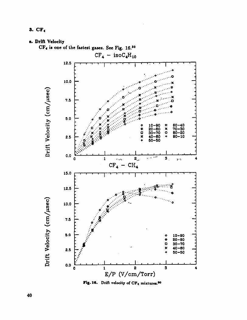
3. CF4
a. Drift VelocityCF4 is one of the fastestgases.SeeFig. 16.°
CF4 - isoC4H10I I I I I
j
‘I.
t:.
0.
CI,a11
C,
.4-,- _4
C.,0a,
-4-,44-4- rlI-,
12.5
10.0
7.5
5.0
2.5
0.04
C..-
*4-.4-4
0*
--I-_
,
fl
7.5--::
.... -
:1-
:z-,
2.5 -
:..
!
:0.0 *
.
-
-
0t0
K+
10-9020-8030-7040-6050-50
.
.
:-
.
:-
:.
.,
II - , I
I.I I I
I4 I ,
0 1 2 3
E/P V/crn/TorrFig. it Drift velocity of CF4 mixtures.3°
4
0.4
-00*
o 10-90* 20-80o so-toX 40-80+ 50-50
fl 80-40K 70-30o 80-20+ 90-10
I I * . . . I0 1 ... 2 3
CF4 - CH4
40

b. Spatial Resolution
Since CF4 is a fast gas,we might expect that its diffusion coefficient would be large.In fact this is not the case. B. Schmidt and S. Polenz3’ measuredthe longitudinaland transversediffusion coefficientsfor CF4 andAr/CF4 80/20 asshownin Fig. 17.Similar measurementsfor Ar/Cl!4 areshownin Fig. 18 for comparison.
£LtCV CF4 so’ceV
lot
s0’. . -u_ Inpat 1,J tharmd limit
EINTdI0*2 100 -‘
102 ..0*l *‘0 .*‘102
101 -I 101Az/CF4 50:20 c,,eV ArICF4 50:20
100 a lot
.
tM,mol t,mit 10’ thIm.I unit
I /-
EINTdJ . EINTd 1Io2 -.-.-..J to.: .1
io I0’ sQ 10’ lo io 102
Lorigstudinaldiffusion ii. pun CF, andAr/CF. 80: 20 TransvaiediffuSe in pwe CF4 and Ar/CF80 :20.
Pig. it
The longitudinal diffusion of CF4 is around the thermal limit up to very high-Efields. From Fig. 17 we can estimatethe position resolution limit of CF4 no directmeasurementsappearto be reportedyet.According to definition of the diffusion coefficient wehave
‘V
41

NI
IS.
NWI
I.,
E,NW
m’ - -- CI ml
r. 7. Itusc,e diffuSe m Cli. and At/CH. 410:5*
avç.tS will the aad.C I.c.n MamasCa
Fig. ii.
CH4 -. ‘
aIadSdtItlIII s414a & WNII. 111171
.
.2
*IbS4
-
*4
Cal lidSI -
I -
SI
It1
t,,!ItV -
ElM lid
*11tH4 10:10
m/SI
h 3 ?‘wa dilTam. a Cli. ad At/CIt. 90:50wsd nub oiha apwinwnIs and th.t.c In Icky....
aSSail.. ioIld U...
in which D is thediffusion coefficient,v is the drift velocity, and z is the drift length.With the parametere definedas
it follows that
DC = cE-,
V
05 = ‘*1 -.
y cE
If E/N = 2 V/cmTorr, and z = 2.6 mm, thenfrom Fig. 17 we find CL 0.026 eV,yielding
a- 30 pm.
Whenvery fine strawtubesareused,a concernis lossof efficiency due to lack of anyprimary ionization. [A low ionization densityalsoleadsto poor spatial resolution]
J. Fischerci 1.32 reportedthe resultssummarizedin Table V at 1 atm..
d. Stability of the Gas Discharge
CF alone is not sufficiently self-quenchingasto be usedas a countergas. Reasonably denseadditivesare neopentane[CCR34] at small concentration10-20%, orisobutane.
CF4 attacheselectronsmainly via dissociativeattachmentprocessesoccurringat electron energiesabove 4.5 eV, with a cross-sectionmaximaat 6 to 715 eV.
c. Prhnary-Ionizstion-Cluster Denshy
çfrv CR4-- SdI4I Ia
EINflS
WI ,l I
cM AUdi 50:10__. -
- 1151111 1S1
CI
l0
42

The energyresolutionobservedwith an Fe55 sourcein CF4 gasmixturesis asgood as
in P-b." SeeTable VI.
Table V.
ElectronGas per
molecule
Average Minimum gasprimary thickness
cluster/cm for 6 clusters
CR4 10 12 5mmC2H3 14 17 3.5
Ar+10% CH4 17 20,16 3,3.6C2!!6 18 21 2.8CO2 22 26 2.3C3H5 26 30 2.0
i-C4H50 34 40 1.5CF4alone 42 --: 50 e attachment losses
CF4in gasmixture 42 41 1.4CCH34 42 50 1.2
Efficiency for singleclusterdetectionq 1 - when N 6, 11 99.8%.
Table VI.
Gas mixture Pulseheight resolution -
100% CF4 75%80% CF4 + 20% isobutane
or 22%80% CF4 + 20% CCH34
90%Ar+10%CR4 t20%
e. Ageing Effects
Excellent! R. Openshawci at." found that a CF4/isobutane80/20 mixture showedeffectively zeropulse-heightdegradationto accumulatedchargesexceeding5 C/cm.Their resultsareshownin Fig. 19. It would seemthat in the CF4fisobutanemixturepolymerizationdoesnot occurundertypical MWPC conditions. This is likely due toCF4 beingableto combinewith polymerprecursorsforming stablevolatile species.
43

£ Conclusion -
CF4/isobutane80/20:* Negligible ageingup to 1.2 C/cm34 or 5.0 C/cm.33* Fastgas12 cm/psec.* Small longitudinal diffusion.* High linear ionization density.
* Very attractivecandidatefor BCD and SSC tracking devices.
It -1:23 A:/Ijh
SOSO
E:4.
06SIopi- t,C/cni
04 . tpslrt-aIII -3 2,07* Lt-:.Itr -91,10
" 02 9OWIISItOtI1 OO05
00 -00 04 08 *2 56 20 24 28 32
- Actuniuhited CI,.. ,t * çpb P
I?? P/llO12 60:20
.4c 10= V"5’ *4JS ._Sl t.’
-08 -
06 SIupt mi
- 0’ Upstream 00,05Center 00:05
02 ‘ bawI,SIIenifl 00:05
0000 04 08 ‘2 16 20 24 28
At Ui,tulal td C*inrc IC/ri. I
;22 Ar/Eth/F15.2 4848’
t1
C. 10 V -...r -
08
06shape tL-C cm
0£ 1. tpst Itd111 l5lO2 * Center ISslO
02 Downslrv.an, 20:10
00 -00 04 08 ‘2 16
AvtiitiiuIul rd 111.11gm It III
$ S.n.ple Ierftl.qe puke h.p. tb...j.. .t’An..wla’.deIge -. I.. Aqr.Ih. crji.. ..4 sq./Cr.
Fig. is.
44

References
1. BCD Collaboration, Bottom Collide: DetectorBCD: An Intermediate-and Low-P1 Detector fortheSSC,SSC-240Sept. 29, 1989.
2. ft. DeSalvo, A Proposal for an SSC Central Tracking Detector, Cornell U. Preprint CLNS87/521987.
3. M. Frautachici at, The AmyInner Tracking Chamber,Ohio State U. preprint Oct. 1989, submitted to Nuci. Instr. Meth. -
4. H. Castroci a!., Proposalfor Researchand Development:Vertexing, Trackingand Data Acquisitionfor a Bottom Collider Detector,Jan. 1, 1989, approved through 1990 by the Fermilab PAC, Jan.30, 1989.
5. G.V. Sainsonov,Ed., The OxideHandbookIFI/Plenum, New York, 1973.
6. H. Ogren, reported at the SSC Tracking Workshop Vancouver, 1989.7. W. Diethorn, NYO-6628 1956. See also ref. 27.
8. M.E. Roseand S.A. Korff An Investigationof the Propertiesof Proportional Counters,Phys. Rev.59, 850 1941.
9. For example, M. Calvetti ritz!., A Computer-AidedSystemfor MWPC Wire TensionControl, Nuc.Instr. Meth. 174, 285 1980.
10. L. Callewaert ci a!., Front End and SignalProcessingElectronicsfor Detectorsat High Luminosity,UPR-162E 1988.
11, F.M. Newcomer ci at, High-SpeedBipolar IntegratedCircuits for SSCApplications,to be publishedin Nuci. ln.tr. Meth.
12. U. Penn ci a!., SSCSubsystemProposalfor Front-EndElectronics, Sept. 1989.
13. A.E. Stevens ci at, A Past Low-Power Time-to-VoltageConverter for High Luminosity ColllderDetectorsNov. 1988.
14. E. Aren, ci at, SSCDetectorR&D Proposal: Developmentof Technologyfor Pixel VertexDetector,Sept. 1989.
15. Y. Arai and 1’. Ohsugi, TMC - A CMOS Time to Digital Converter, KEK Preprint 88-78 Nov.1988.
16. L.D. Gladney et at, Proposalto the SSCLaboratory for Researchand Developmentfor a ParallelComputingFarm, Sept. 1989.
17. ft. Kadel, On SenseWire Currentsin the CTC, CDF/MEMO/TRACKING/CDFR/632 Feb. 25,1988.
18. MARK Ill Collaboration, The MARK III Vertex Chamber: StudiesUsing DME, NIM A265, 851988.
19. F, Villa, Dimethylether:A Low Velocity, Low Diffusion Drift ChamberGas, MM 217, 273 1983.20. M. Bulk ci at, Dimethyl Ether Reviewed: NewResultson Using This Gas in a High-Precision
Drift Chamber,NIM A239, 497 1985.21. G. Sari et at, DimethylEther as a Drift-Chamber Gas, NIM A25i, 292 1986.22. M. Jibaly ci at, An AgeingStudyof Wire Chamberswith DimethylEther: Effectsof Wire Material
and Freon Content,IEEE NS-30, No.1, 552 1989.23. S. Majewaki, Proc. Workshop on Radia. Damageto Wire Chambers,LBL-21170 1986, p.239.24. B. Zhou et at, UsingDimethyletheras a Drift gas in a High Precision Drift TubeDetector.
25. M. Jibaly ci a!., SomeResultson the Ageingof Wire Chamberswith DimethylEther,NIM .213,161 1988.
26. W.W. Ash et at, Design, Construction,PrototypeTestsand Performanceof a VertexChamberforthe MAC Detector,MM AiM, 399 1987.
27. LF. Knoll, Radiation Detectionand Measurement,Wiley, New York, 1987.
45

28. A. Peisert and F. Sauli, Drift and Diffusion of Electrons in Gases: A Compilation, CERN 84-081984.
29. 1. Pandoulas ci a!., The L3 Experiment,presentedat the 1987 Europhysics ConferenceUppsala,Sweden,sessionS.
30. T. Yamashita ci at, Measurementsof the Electron Drift Velocity and PositiveIon Mobility for theGasesContainingCF4.
31. B. Schmidt and S. Polens, ElectronMotion in CountingGases- NewAnswersand new Questions,NIM A273,488 1988.
32. J. Fischer et a!., Proportional Chambersfor Very High CountingRatesBasedon Gas Mixtures ofCF4 With Hydrocarbons,NIM A238, 249 1985.
33. ft. Openshaw ci a!., Testsof Wire ChamberAgeing with CF4/Isobutane80:20, Argon/Ethane50:50, and Argon/Etkane/CF4 48z4&4, IEEE NS-3t, UT 198%.
34. J. Kadyk, New ResultsFrom Wire ChamberAgeing Tests, SSC ‘flacking Workshop Vancouver,July, 1989.
46