Embed Size (px)
Citation preview

OREGON STATE UNIVERSITY
2019 NASA SL TEAM
104 KERR ADMIN BLDG. # 1011
CORVALLIS, OR 97331
Proposal
September 19, 2018
USLI Proposal - Oregon State University
CONTENTS
1 General Information 7
1.1 Leadership Overview . . . . . . . . . . . . . . . . . . . . . . . . . . . . . . . . . . . . . . 7
1.2 Team Structure and Organization . . . . . . . . . . . . . . . . . . . . . . . . . . . . . . . 7
2 Facilities and Equipment 9
2.1 Accessible Equipment . . . . . . . . . . . . . . . . . . . . . . . . . . . . . . . . . . . . . 9
2.2 Accessible Software . . . . . . . . . . . . . . . . . . . . . . . . . . . . . . . . . . . . . . . 11
2.3 Communication . . . . . . . . . . . . . . . . . . . . . . . . . . . . . . . . . . . . . . . . . 12
3 Safety 13
3.1 Safety Agreement . . . . . . . . . . . . . . . . . . . . . . . . . . . . . . . . . . . . . . . . 13
3.2 Risk Assessment . . . . . . . . . . . . . . . . . . . . . . . . . . . . . . . . . . . . . . . . 13
3.3 Safety Briefings . . . . . . . . . . . . . . . . . . . . . . . . . . . . . . . . . . . . . . . . . 16
3.4 Caution Statements . . . . . . . . . . . . . . . . . . . . . . . . . . . . . . . . . . . . . . . 16
3.5 Rocket Motor Handling . . . . . . . . . . . . . . . . . . . . . . . . . . . . . . . . . . . . 17
3.6 NAR Procedures/ Personnel . . . . . . . . . . . . . . . . . . . . . . . . . . . . . . . . . . 17
3.7 Law Compliance . . . . . . . . . . . . . . . . . . . . . . . . . . . . . . . . . . . . . . . . 17
3.8 Safety Verification Matrix . . . . . . . . . . . . . . . . . . . . . . . . . . . . . . . . . . . 17
4 Technical Design 20
4.1 Vehicle Specifications . . . . . . . . . . . . . . . . . . . . . . . . . . . . . . . . . . . . . . 20
4.2 Projected Altitude . . . . . . . . . . . . . . . . . . . . . . . . . . . . . . . . . . . . . . . . 24
4.2.1 Projected Altitude Adjustment . . . . . . . . . . . . . . . . . . . . . . . . . . . 24
4.2.1.1 Testing . . . . . . . . . . . . . . . . . . . . . . . . . . . . . . . . . . . . . . . 25
4.2.1.2 Mechanical System . . . . . . . . . . . . . . . . . . . . . . . . . . . . . . . . 26
4.2.1.3 Electrical System . . . . . . . . . . . . . . . . . . . . . . . . . . . . . . . . . 27
4.2.1.4 Control System . . . . . . . . . . . . . . . . . . . . . . . . . . . . . . . . . . 27
4.3 Recovery System . . . . . . . . . . . . . . . . . . . . . . . . . . . . . . . . . . . . . . . . 28
4.3.1 Separation Events and Descent . . . . . . . . . . . . . . . . . . . . . . . . . . . 28
4.3.2 Altimeters . . . . . . . . . . . . . . . . . . . . . . . . . . . . . . . . . . . . . . 29
4.3.2.1 Accurate Pressure Readings . . . . . . . . . . . . . . . . . . . . . . . . . . . 29
4.3.2.2 Number of Static Port Holes . . . . . . . . . . . . . . . . . . . . . . . . . . . 30
4.3.2.3 Backup Charges . . . . . . . . . . . . . . . . . . . . . . . . . . . . . . . . . . 30
4.3.3 Parachutes and Retention . . . . . . . . . . . . . . . . . . . . . . . . . . . . . . 30
4.3.3.1 Fore Parachutes . . . . . . . . . . . . . . . . . . . . . . . . . . . . . . . . . . 30
4.3.3.2 Aft Parachutes . . . . . . . . . . . . . . . . . . . . . . . . . . . . . . . . . . . 31
4.3.4 Shock Cord Material . . . . . . . . . . . . . . . . . . . . . . . . . . . . . . . . 31
1
USLI Proposal - Oregon State University
4.3.5 Parachute Shielding . . . . . . . . . . . . . . . . . . . . . . . . . . . . . . . . . 32
4.3.6 Descent Rates and Parachute Sizes . . . . . . . . . . . . . . . . . . . . . . . . 32
4.3.7 Couplers and Shear Pins . . . . . . . . . . . . . . . . . . . . . . . . . . . . . . 34
4.3.8 Recovery System Verification Matrix . . . . . . . . . . . . . . . . . . . . . . . 34
4.4 Propulsion . . . . . . . . . . . . . . . . . . . . . . . . . . . . . . . . . . . . . . . . . . . . 38
4.5 Launch Vehicle Technical Challenges . . . . . . . . . . . . . . . . . . . . . . . . . . . . . 38
4.6 Payload - Deployable Rover . . . . . . . . . . . . . . . . . . . . . . . . . . . . . . . . . . 41
4.6.1 Payload Overview . . . . . . . . . . . . . . . . . . . . . . . . . . . . . . . . . . 41
4.6.2 Payload Ejection and Retention System . . . . . . . . . . . . . . . . . . . . . . 43
4.6.3 Payload Details . . . . . . . . . . . . . . . . . . . . . . . . . . . . . . . . . . . 45
4.6.3.1 Soil Collection . . . . . . . . . . . . . . . . . . . . . . . . . . . . . . . . . . . 47
4.6.3.2 Electrical Design . . . . . . . . . . . . . . . . . . . . . . . . . . . . . . . . . 48
4.6.4 Rover-Related Technical Challenges and Solutions . . . . . . . . . . . . . . . . 49
4.6.5 Rover Test Plan . . . . . . . . . . . . . . . . . . . . . . . . . . . . . . . . . . . 50
4.7 Project Requirements . . . . . . . . . . . . . . . . . . . . . . . . . . . . . . . . . . . . . . 51
4.7.1 Vehicle Prohibitions . . . . . . . . . . . . . . . . . . . . . . . . . . . . . . . . . 55
5 STEM Engagement 57
6 Project Plan 58
6.1 Schedule . . . . . . . . . . . . . . . . . . . . . . . . . . . . . . . . . . . . . . . . . . . . . 58
6.2 Budget . . . . . . . . . . . . . . . . . . . . . . . . . . . . . . . . . . . . . . . . . . . . . . 62
6.3 Funding . . . . . . . . . . . . . . . . . . . . . . . . . . . . . . . . . . . . . . . . . . . . . 68
6.4 Sustainability . . . . . . . . . . . . . . . . . . . . . . . . . . . . . . . . . . . . . . . . . . 69
2

USLI Proposal - Oregon State University
LIST OF TABLES
1 Adult Educator Summary Chart . . . . . . . . . . . . . . . . . . . . . . . . . . . . . . . . . . . . 7
2 Team Leadership Chart . . . . . . . . . . . . . . . . . . . . . . . . . . . . . . . . . . . . . . . . . 7
3 Risk Assessment . . . . . . . . . . . . . . . . . . . . . . . . . . . . . . . . . . . . . . . . . . . . . 14
4 Safety Verification Matrix . . . . . . . . . . . . . . . . . . . . . . . . . . . . . . . . . . . . . . . . 18
5 Launch Vehicle Specifications . . . . . . . . . . . . . . . . . . . . . . . . . . . . . . . . . . . . . . 21
6 Launch Vehicle Verification Matrix . . . . . . . . . . . . . . . . . . . . . . . . . . . . . . . . . . . 22
7 Values for Coefficient of Drag and Air Density . . . . . . . . . . . . . . . . . . . . . . . . . . . . 33
8 Recovery System Verification Matrix . . . . . . . . . . . . . . . . . . . . . . . . . . . . . . . . . . 35
9 Motor Specifications . . . . . . . . . . . . . . . . . . . . . . . . . . . . . . . . . . . . . . . . . . . 38
11 Launch Vehicle Technical Challenges . . . . . . . . . . . . . . . . . . . . . . . . . . . . . . . . . . 39
12 Rover Payload Requirements. . . . . . . . . . . . . . . . . . . . . . . . . . . . . . . . . . . . . . . 42
13 EARS Technical Challenges and Solutions . . . . . . . . . . . . . . . . . . . . . . . . . . . . . . . 45
14 GHM-04 Motor Specifications. . . . . . . . . . . . . . . . . . . . . . . . . . . . . . . . . . . . . . . 46
15 PGHM-01 Motor Specifications. . . . . . . . . . . . . . . . . . . . . . . . . . . . . . . . . . . . . . 48
16 Rover Technical Challenges and Solutions . . . . . . . . . . . . . . . . . . . . . . . . . . . . . . . 49
17 Rover Test Plan . . . . . . . . . . . . . . . . . . . . . . . . . . . . . . . . . . . . . . . . . . . . . . 50
18 Vehicle Requirement Verification Matrix . . . . . . . . . . . . . . . . . . . . . . . . . . . . . . . . 51
19 Vehicle Prohibition Verification Matrix . . . . . . . . . . . . . . . . . . . . . . . . . . . . . . . . . 56
20 Section codes for use in budget tables. . . . . . . . . . . . . . . . . . . . . . . . . . . . . . . . . . 62
21 Structures Budget . . . . . . . . . . . . . . . . . . . . . . . . . . . . . . . . . . . . . . . . . . . . . 63
22 Aerodynamics and Recovery Budget . . . . . . . . . . . . . . . . . . . . . . . . . . . . . . . . . . 63
23 Payload Budget . . . . . . . . . . . . . . . . . . . . . . . . . . . . . . . . . . . . . . . . . . . . . . 65
24 Projected Travel Expenses . . . . . . . . . . . . . . . . . . . . . . . . . . . . . . . . . . . . . . . . 67
3
USLI Proposal - Oregon State University
LIST OF FIGURES
1 Team Organization . . . . . . . . . . . . . . . . . . . . . . . . . . . . . . . . . . . . . . . . . . . . 8
2 Fadal VMC 3016 Milling Machine . . . . . . . . . . . . . . . . . . . . . . . . . . . . . . . . . . . . 9
3 Graf Hall Work Space . . . . . . . . . . . . . . . . . . . . . . . . . . . . . . . . . . . . . . . . . . 10
4 Additive Manufacturing Machines . . . . . . . . . . . . . . . . . . . . . . . . . . . . . . . . . . . 10
5 MIME Wood Shop . . . . . . . . . . . . . . . . . . . . . . . . . . . . . . . . . . . . . . . . . . . . 10
6 AIAA Lab . . . . . . . . . . . . . . . . . . . . . . . . . . . . . . . . . . . . . . . . . . . . . . . . . 11
7 Launch Vehicle Equipment Layout . . . . . . . . . . . . . . . . . . . . . . . . . . . . . . . . . . . 20
8 OpenRocket Simulation . . . . . . . . . . . . . . . . . . . . . . . . . . . . . . . . . . . . . . . . . 21
9 BEAVS design displaying bladed system. . . . . . . . . . . . . . . . . . . . . . . . . . . . . . . . 25
10 Launch Vehicle Flight (not drawn to scale). . . . . . . . . . . . . . . . . . . . . . . . . . . . . . . 29
11 Tender Descender . . . . . . . . . . . . . . . . . . . . . . . . . . . . . . . . . . . . . . . . . . . . . 31
12 Deployment Bag Closure . . . . . . . . . . . . . . . . . . . . . . . . . . . . . . . . . . . . . . . . . 32
13 EARS Assembly Prior to Airframe Insertion . . . . . . . . . . . . . . . . . . . . . . . . . . . . . . 44
14 EARS Assembly into Airframe . . . . . . . . . . . . . . . . . . . . . . . . . . . . . . . . . . . . . 45
15 Rover Drivetrain . . . . . . . . . . . . . . . . . . . . . . . . . . . . . . . . . . . . . . . . . . . . . 47
16 Soil Collection Device . . . . . . . . . . . . . . . . . . . . . . . . . . . . . . . . . . . . . . . . . . 47
17 OSRT’s Schedule for 2018-2019 USLI (1/3) . . . . . . . . . . . . . . . . . . . . . . . . . . . . . . . 59
18 OSRT’s Schedule for 2018-2019 USLI (2/3) . . . . . . . . . . . . . . . . . . . . . . . . . . . . . . . 60
19 OSRT’s Schedule for 2018-2019 USLI (3/3) . . . . . . . . . . . . . . . . . . . . . . . . . . . . . . . 61
20 AIAA and its Current Partnership Network . . . . . . . . . . . . . . . . . . . . . . . . . . . . . . 68
4
USLI Proposal - Oregon State University Acronym Dictionary
ACRONYM DICTIONARY
9DOF Nine Degree of Freedom. 27
AGL Above Ground Level. 11, 28, 31, 35, 51
AIAA American Institute of Aeronautics and Astronautics. 7, 11, 68, 69
APCP Ammonium Perchlorate Composite Propellant. 52
ARRD Advanced Retention and Release Device. 42, 44
ATI Allegheny Technologies Incorporated. 68
BEAVS Blade Extending Apogee Variance System. 20, 24–28, 62
CAR Canadian Association of Rocketry. 52
CDR Critical Design Review. 12, 53
CFD Computational Fluid Dynamics. 27
CNC Computer Numerical Control. 9, 26
DC Direct Current. 46
EARS Ejection and Retention System. 43, 44
EDM Electrical Discharge Machining. 9
FAA Federal Aviation Administration. 17, 52
FDM Fused Deposition Modeling. 26
FMEA Failure Mode Effects Analysis. 18
FRR Flight Readiness Review. 12, 53
GPS Global Positioning System. 36
HDPE High-density polyethylene. 43–45
JHA Job Hazard Analysis. 16, 18, 19
LED Light Emitting Diode. 19
LiPo Lithium Polymer. 18, 48
MIME Mechanical, Industrial, and Manufacturing Engineering. 9, 10, 12
MPRL Machine Product and Realization Laboratory. 9, 18
MSDS Material Safety Data Sheet. 14, 16
NAR National Association of Rocketry. 17, 18, 52
NASA National Aeronautics and Space Administration. 52, 53, 57
NEMA National Electrical Manufacturers Association. 26
5
USLI Proposal - Oregon State University
NFPA National Fire Protection Agency. 17
OROC Oregon Rocketry. 17
OSGC Oregon Space Grant Consortium. 68
OSRT Oregon State Rocket Team. 7, 9–13, 17, 21, 24–29, 34, 38, 51, 55, 57, 68, 69
OSSEP Oregon Space Science Education Program. 57
OSU Oregon State University. 18, 57, 69
PCB Printed Circuit Board. 27
PDR Preliminary Design Review. 12, 51
PID Proportional-Integral-Derivative. 27, 28
PLA Polylactic Acid. 26
PPE Personal Protective Equipment. 13, 14, 16, 19
ROS Robot Operating System. 12
RRC3 Rocket Recovery Controller 3. 29, 36
RSO Range Safety Officer. 13, 35, 52
SO Safety Officer. 13, 16, 18
STEM Science, Technology, Engineering and Mathematics. 57, 69
STP Standard Temperature and Pressure. 33
TRA Tripoli Rocketry Association, Inc.. 17, 18, 52
USLI University Student Launch Initiative. 13, 26, 41
6
USLI Proposal - Oregon State University 1.2 Team Structure and Organization
1 GENERAL INFORMATION
1.1 Leadership Overview
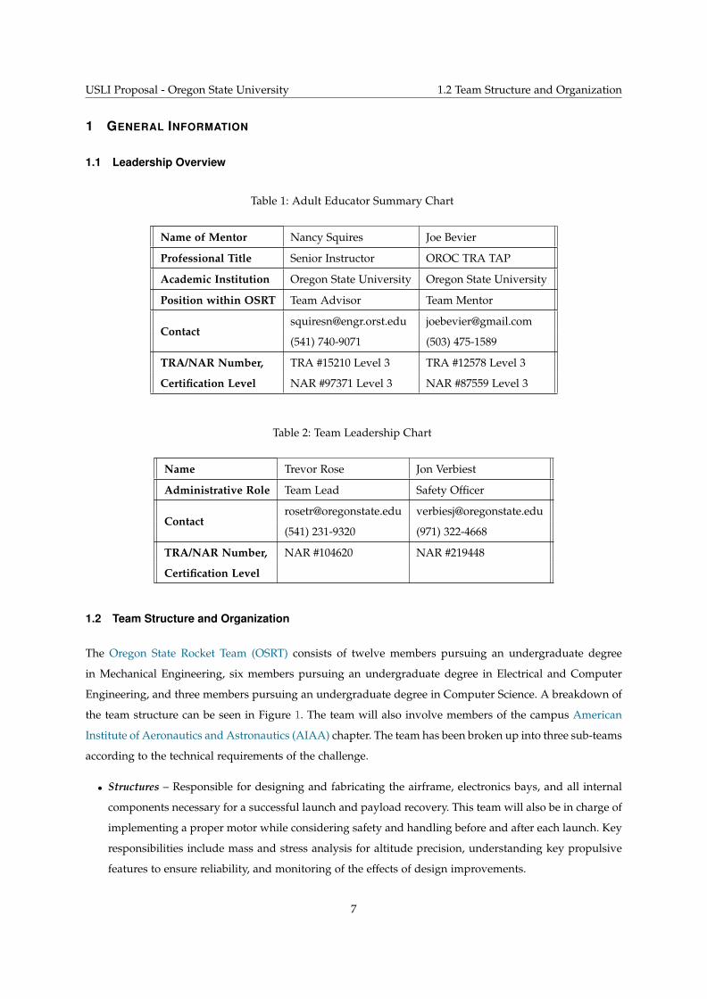
Table 1: Adult Educator Summary Chart
Name of Mentor Nancy Squires Joe Bevier
Professional Title Senior Instructor OROC TRA TAP
Academic Institution Oregon State University Oregon State University
Position within OSRT Team Advisor Team Mentor
[email protected] [email protected]
(541) 740-9071 (503) 475-1589
TRA/NAR Number, TRA #15210 Level 3 TRA #12578 Level 3
Certification Level NAR #97371 Level 3 NAR #87559 Level 3
Table 2: Team Leadership Chart
Name Trevor Rose Jon Verbiest
Administrative Role Team Lead Safety Officer
[email protected] [email protected]
(541) 231-9320 (971) 322-4668
TRA/NAR Number, NAR #104620 NAR #219448
Certification Level
1.2 Team Structure and Organization
The Oregon State Rocket Team (OSRT) consists of twelve members pursuing an undergraduate degree
in Mechanical Engineering, six members pursuing an undergraduate degree in Electrical and Computer
Engineering, and three members pursuing an undergraduate degree in Computer Science. A breakdown of
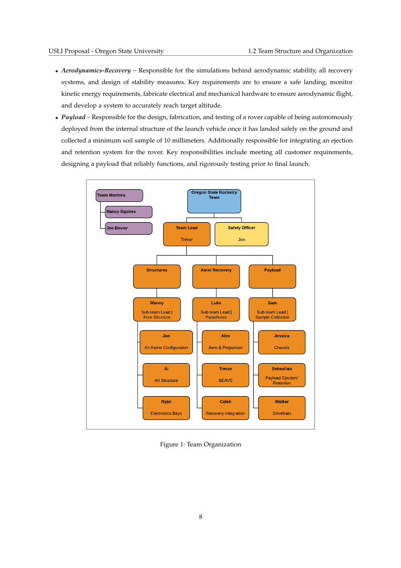
the team structure can be seen in Figure 1. The team will also involve members of the campus American
Institute of Aeronautics and Astronautics (AIAA) chapter. The team has been broken up into three sub-teams
according to the technical requirements of the challenge.
• Structures – Responsible for designing and fabricating the airframe, electronics bays, and all internal
components necessary for a successful launch and payload recovery. This team will also be in charge of
implementing a proper motor while considering safety and handling before and after each launch. Key
responsibilities include mass and stress analysis for altitude precision, understanding key propulsive
features to ensure reliability, and monitoring of the effects of design improvements.
7
USLI Proposal - Oregon State University 1.2 Team Structure and Organization
• Aerodynamics-Recovery – Responsible for the simulations behind aerodynamic stability, all recovery
systems, and design of stability measures. Key requirements are to ensure a safe landing, monitor
kinetic energy requirements, fabricate electrical and mechanical hardware to ensure aerodynamic flight,
and develop a system to accurately reach target altitude.
• Payload – Responsible for the design, fabrication, and testing of a rover capable of being autonomously
deployed from the internal structure of the launch vehicle once it has landed safely on the ground and
collected a minimum soil sample of 10 millimeters. Additionally responsible for integrating an ejection
and retention system for the rover. Key responsibilities include meeting all customer requirements,
designing a payload that reliably functions, and rigorously testing prior to final launch.
Figure 1: Team Organization
8
USLI Proposal - Oregon State University 2. Facilities and Equipment
2 FACILITIES AND EQUIPMENT
2.1 Accessible Equipment
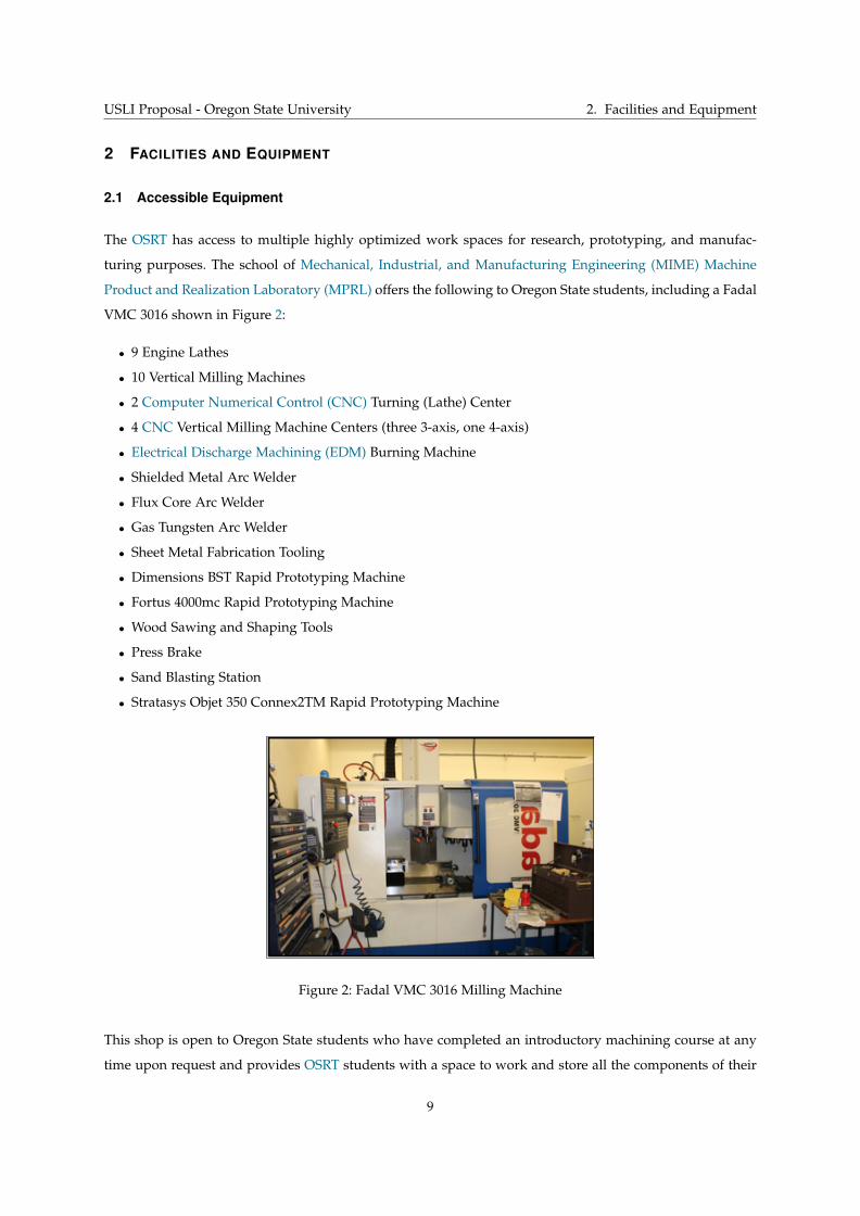
The OSRT has access to multiple highly optimized work spaces for research, prototyping, and manufac-
turing purposes. The school of Mechanical, Industrial, and Manufacturing Engineering (MIME) Machine
Product and Realization Laboratory (MPRL) offers the following to Oregon State students, including a Fadal
VMC 3016 shown in Figure 2:
• 9 Engine Lathes
• 10 Vertical Milling Machines
• 2 Computer Numerical Control (CNC) Turning (Lathe) Center
• 4 CNC Vertical Milling Machine Centers (three 3-axis, one 4-axis)
• Electrical Discharge Machining (EDM) Burning Machine
• Shielded Metal Arc Welder
• Flux Core Arc Welder
• Gas Tungsten Arc Welder
• Sheet Metal Fabrication Tooling
• Dimensions BST Rapid Prototyping Machine
• Fortus 4000mc Rapid Prototyping Machine
• Wood Sawing and Shaping Tools
• Press Brake
• Sand Blasting Station
• Stratasys Objet 350 Connex2TM Rapid Prototyping Machine
Figure 2: Fadal VMC 3016 Milling Machine
This shop is open to Oregon State students who have completed an introductory machining course at any
time upon request and provides OSRT students with a space to work and store all the components of their
9

USLI Proposal - Oregon State University 2.1 Accessible Equipment
projects. Some of this work and storage space is shown in Figure 3.
Figure 3: Graf Hall Work Space
In the MIME Rapid Prototyping Lab are three additive manufacturing machines (a Stratasys Objet Con-
nex2TM, a Fortus 400mc, and a Dimension BST 1200es) along with a fully furnished wood shop. This
allows OSRT students rapid prototyping abilities and are shown in Figures 4 and 5.
Figure 4: Additive Manufacturing Machines
Figure 5: MIME Wood Shop
10
USLI Proposal - Oregon State University 2.2 Accessible Software
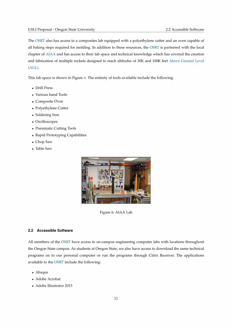
The OSRT also has access to a composites lab equipped with a polyethylene cutter and an oven capable of
all baking steps required for molding. In addition to these resources, the OSRT is partnered with the local
chapter of AIAA and has access to their lab space and technical knowledge which has covered the creation
and fabrication of multiple rockets designed to reach altitudes of 30K and 100K feet Above Ground Level
(AGL).
This lab space is shown in Figure 6. The entirety of tools available include the following:
• Drill Press
• Various hand Tools
• Composite Oven
• Polyethylene Cutter
• Soldering Iron
• Oscilloscopes
• Pneumatic Cutting Tools
• Rapid Prototyping Capabilities
• Chop Saw
• Table Saw
Figure 6: AIAA Lab
2.2 Accessible Software
All members of the OSRT have access to on-campus engineering computer labs with locations throughout
the Oregon State campus. As students at Oregon State, we also have access to download the same technical
programs on to our personal computer or run the programs through Citrix Receiver. The applications
available to the OSRT include the following:
• Abaqus
• Adobe Acrobat
• Adobe Illustrator 2015
11
USLI Proposal - Oregon State University 2.3 Communication
• Adobe InDesign 2015
• Adobe Photoshop 2015
• ANSYS
• CES EduPack 2016
• Engineering Equation Solver
• LaTeX
• Mathematica
• MATLAB
• Microsoft Office
• Minitab
• OpenRocket
• RASAero II
• Sketchup
• Solidworks 2018
• STAR-CCM+
Additionally, OSRT members will utilize standard programming languages (ex. C, C++, Python) and open
source software packages (ex. Git, Robot Operating System (ROS)) in the development of the software
systems necessary for launch vehicle operation. Similar resources will be utilized for logistic and docu-
mentation projects such as the team website and technical documents. Team members studying computer
science or electrical engineering at Oregon State have access to university hosted servers that will streamline
the process of developing, debugging, and deploying all necessary software deliverables.
2.3 Communication
The OSRT will be expected to provide video conferencing capabilities in order to present its Preliminary
Design Review (PDR), Critical Design Review (CDR), and Flight Readiness Review (FRR) to a panel of
NASA employees. All the equipment needed to conduct a successful video teleconference will be provided
by the OSRT and Oregon State Department of MIME. The facilities provided by Oregon State University
include designated rooms equipped with high quality speakers, projectors, and cameras. Also provided
by the University is in room support, which handle all the electronics, to ensure the teleconferences run
smoothly.
12
USLI Proposal - Oregon State University 3. Safety
3 SAFETY
3.1 Safety Agreement
All members of the OSRT have read and will comply with the following safety agreement:
Oregon State Rocketry Team Safety Agreement
I, ________, have read, understood, and will abide by all laws and regulations set forth by the National Association of
Rocketry, the Federal Aviation Administration, the National Fire Protection Association, and Oregon State University
while handling, working on or when in the presence of high powered rockets. This includes being properly certified
and wearing all required Personal Protective Equipment (PPE) when appropriate. I understand that these laws and
regulations are for my safety and the safety of others. I will use my best judgment in University Student Launch
Initiative (USLI) matters to keep myself and others safe and I will follow guidelines and procedures set by the Safety
Officer (SO). The Range Safety Officer (RSO) will inspect the rocket before any launch to ensure the rocket meets all
range safety requirements and I understand that the RSO has the final say on the status of any launch. I understand
that any launches unapproved by the RSO are strictly prohibited. I understand that any violation of the above is
grounds for removal from the team or further action if offense warrants.
Signature: _________________ Date: _______
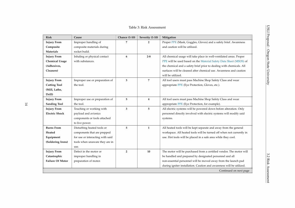
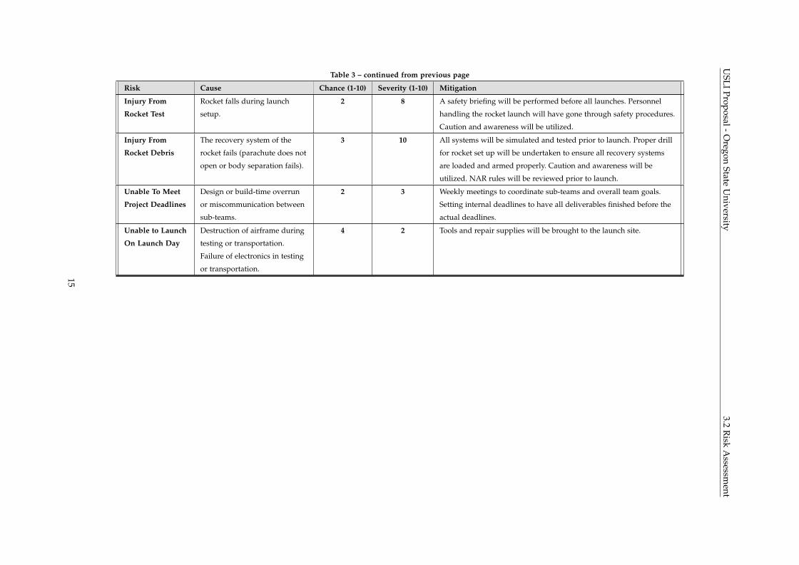
3.2 Risk Assessment
Shown in Table 3 is an analysis of risks to the mission and personnel and how these risks are being mitigated
by OSRT.
13
USLI
Proposal-Oregon
StateU
niversity3.2
Risk
Assessm
entTable 3: Risk Assessment
Risk Cause Chance (1-10) Severity (1-10) Mitigation
Injury From
Composite
Materials
Improper handling of
composite materials during
rocket build.
7 2 Proper PPE (Mask, Goggles, Gloves) and a safety brief. Awareness
and caution will be utilized.
Injury From
Chemical Usage
(Adhesives,
Cleaners)
Inhaling or physical contact
with substances.
6 2-8 All chemical usage will take place in well-ventilated areas. Proper
PPE will be used based on the Material Safety Data Sheet (MSDS) of
the chemical and a safety brief prior to dealing with chemicals. All
surfaces will be cleaned after chemical use. Awareness and caution
will be utilized.
Injury From
Cutting Tool
(Mill, Lathe,
Drill)
Improper use or preparation of
the tool.
3 7 All tool users must pass Machine Shop Safety Class and wear
appropriate PPE (Eye Protection, Gloves, etc.).
Injury From
Sanding Tool
Improper use or preparation of
the tool.
5 4 All tool users must pass Machine Shop Safety Class and wear
appropriate PPE (Eye Protection, for example).
Injury From
Electric Shock
Touching or working with
payload and avionics
components or tools attached
to live power.
3 5 All electric systems will be powered down before alteration. Only
personnel directly involved with electric systems will modify said
systems.
Burns From
Heated
Equipment
(Soldering Irons)
Disturbing heated tools or
components that are prepped
for use or interacting with said
tools when unaware they are in
use.
5 1 All heated tools will be kept separate and away from the general
workspace. All heated tools will be turned off when not currently in
use. Hot tools will be placed in a safe area while they cool.
Injury From
Catastrophic
Failure Of Motor
Defect in the motor or
improper handling in
preparation of motor.
2 10 The motor will be purchased from a certified vendor. The motor will
be handled and prepared by designated personnel and all
non-essential personnel will be moved away from the launch pad
during igniter installation. Caution and awareness will be utilized.
Continued on next page
14
USLI
Proposal-Oregon
StateU
niversity3.2
Risk
Assessm
entTable 3 – continued from previous page
Risk Cause Chance (1-10) Severity (1-10) Mitigation
Injury From
Rocket Test
Rocket falls during launch
setup.
2 8 A safety briefing will be performed before all launches. Personnel
handling the rocket launch will have gone through safety procedures.
Caution and awareness will be utilized.
Injury From
Rocket Debris
The recovery system of the
rocket fails (parachute does not
open or body separation fails).
3 10 All systems will be simulated and tested prior to launch. Proper drill
for rocket set up will be undertaken to ensure all recovery systems
are loaded and armed properly. Caution and awareness will be
utilized. NAR rules will be reviewed prior to launch.
Unable To Meet
Project Deadlines
Design or build-time overrun
or miscommunication between
sub-teams.
2 3 Weekly meetings to coordinate sub-teams and overall team goals.
Setting internal deadlines to have all deliverables finished before the
actual deadlines.
Unable to Launch
On Launch Day
Destruction of airframe during
testing or transportation.
Failure of electronics in testing
or transportation.
4 2 Tools and repair supplies will be brought to the launch site.
15
USLI Proposal - Oregon State University 3.3 Safety Briefings
3.3 Safety Briefings
Proper PPE will be provided to all team members during fabrication, assembly, testing, and operation of
the launch vehicle and payload. During test launches and competition, all team members will follow the
provided instructions and stand a safe distance away from the launch vehicle.
Before any construction of the launch vehicle or fabrication of any components, all members taking part
must attend a safety briefing led by the SO to provide all pertinent warnings for the tools and materials
that will be used. This is to ensure that all team members have a complete understanding of the potential
hazards and the best ways to mitigate them. Members will also be briefed on when to fill out a Job Hazard
Analysis (JHA). Completing a JHA will allow team members to consider all potential hazards associated
with a task and determine the safest way to proceed. If any safety concerns arise from the JHA which cannot
be mitigated to provide a safe work environment, those concerns will be brought to the SO or team mentor
in order to develop different method to complete the task. This alternative method may require a new JHA.
The SO will hold briefings before all launches to provide an overview and refresher on all safety procedures
and launch site regulations. During this briefing, launch checklists will be distributed to all members to
determine that all members understand the plan for the launch and their assigned roles. The distribution of
launch checklists allows for all team members to be observant for deviations from the predetermined plan
that could potentially be dangerous.
3.4 Caution Statements
In addition to safety briefings, caution statements will be placed in work instructions and additional safety
information will be placed in working areas. The caution statements will include possible hazards for the
portion of the build process and the appropriate PPE to mitigate those hazards. Statements will include a
header which describes the potential penalty for failure to adhere to protocol. Examples are shown below.
— CAUTION: Hazard to Equipment —
Attempting to remove logic board while still secured can cause damage and dislodge components.
— CAUTION: Hazard to Personnel —
Attempting to catch a landing launch vehicle can result in injury or death.
All work areas will have signs listing the appropriate PPE for the area and for any tools to be used in that
area. Additionally, all work areas will have easy access to MSDS for all materials that may be use in said
areas and all PPE that would be required to use such materials.
16
USLI Proposal - Oregon State University 3.5 Rocket Motor Handling
3.5 Rocket Motor Handling
Rocket motors will be purchased only by an National Association of Rocketry (NAR)/Tripoli Rocketry
Association, Inc. (TRA) certified instructor. Motors and ejection charges will be stored away from ignition
and heat sources, isolated in specified containers. In addition, NAR/TRA certified instructors will prepare
all motors and ejection charges. Transportation of the rocket motors will be the responsibility of a NAR/TRA
certified mentor. Motors will be purchased on site or transported by car to the launch site.
3.6 NAR Procedures/ Personnel
Our NAR/TRA Level 3 certificatied mentors will be responsible for ensuring the team is in complete
compliance with all NAR High Power Safety Code requirements. Joe Bevier will be responsible for purchase,
storage and transport, and use of rocket motors and energetic devices. Additionally, Joe Bevier will be
present during all ground testing procedures and all launches.
3.7 Law Compliance
OSRT is fully committed to following all laws and regulations pertaining to the building and launching of
high powered rockets. This includes specific attention to Federal Aviation Administration (FAA) regulations
pertaining to the use of airspace for rocket launches and launch sites and the National Fire Protection
Agency (NFPA) codes that govern the use of high powered rocketry (NFPA 1127) to prevent fire caused by
rocket use. For all rocket launches, OSRT will work with Oregon Rocketry (OROC) to obtain the appropriate
waiver for the OROC launch facility in Brothers, OR. All launch activities will be suspended if said waiver
is not issued until the waiver can be obtained.
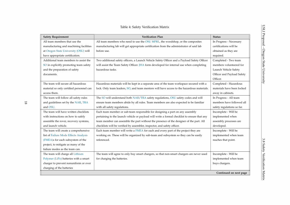
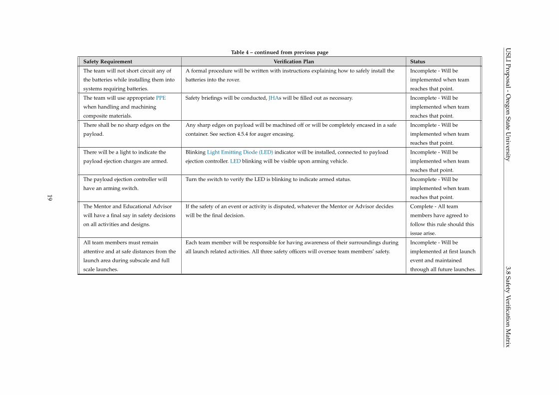
3.8 Safety Verification Matrix
Shown in Table 4 is a breakdown of safety requirements, a brief description of how OSRT is verifying these
requirements will be completed, and the current status of the verification implementation.
17
USLI
Proposal-Oregon
StateU
niversity3.8
SafetyVerification
Matrix
Table 4: Safety Verification Matrix
Safety Requirement Verification Plan Status
All team members that use the
manufacturing and machining facilities
at Oregon State University (OSU) will
have appropriate certification.
All team members who need to use the OSU MPRL, the woodshop, or the composites
manufacturing lab will get appropriate certification from the administrator of said lab
before use.
In Progress - Necessary
certifications will be
obtained as they are
required.
Additional team members to assist the
SO in explicitly promoting team safety
and the preparation of safety
documents.
Two additional safety officers, a Launch Vehicle Safety Officer and a Payload Safety Officer
will assist the Team Safety Officer. JHA form developed for internal use when completing
hazardous tasks.
Completed - Two team
members volunteered for
Launch Vehicle Safety
Officer and Payload Safety
Officer.
The team will secure all hazardous
material so only certified personnel can
access them.
Hazardous materials will be kept in a separate area of the team workspace secured with a
lock. Only team leaders, SO, and team mentors will have access to the hazardous materials.
Completed - Hazardous
materials have been locked
away in cabinets.
The team will follow all safety rules
and guidelines set by the NAR, TRA
and OSU.
The SO will understand both NAR/TRA safety regulations, OSU safety codes and will
ensure team members abide by all rules. Team members are also expected to be familiar
with all safety regulations.
In Progress - All team
members have followed all
safety regulations so far.
The team will have written checklists
with instructions on how to safely
assemble the rover, recovery systems,
and launch vehicle.
Each team member or sub-team responsible for designing a part on any assembly
pertaining to the launch vehicle or payload will write a formal checklist to ensure that any
team member can assemble the part without the presence of the designer of the part. All
checklists will be verified by assembler, inspector, and safety officer.
Incomplete - Will be
implemented when
assembly processes are
developed.
The team will create a comprehensive
list of Failure Mode Effects Analysis
(FMEA)s for each subsystem of the
project, to mitigate as many of the
failure modes as the team can.
Each team member will write a FMEA for each and every part of the project they are
working on. These will be organized by sub-team and subsystem so they can be easily
referenced.
Incomplete - Will be
implemented when team
reaches that point.
The team will charge all Lithium
Polymer (LiPo) batteries with a smart
charger to prevent nonuniform or over
charging of the batteries
The team will agree to only buy smart chargers, so that non-smart chargers are never used
for charging the batteries.
Incomplete - Will be
implemented when team
buys chargers.
Continued on next page
18
USLI
Proposal-Oregon
StateU
niversity3.8
SafetyVerification
Matrix
Table 4 – continued from previous page
Safety Requirement Verification Plan Status
The team will not short circuit any of
the batteries while installing them into
systems requiring batteries.
A formal procedure will be written with instructions explaining how to safely install the
batteries into the rover.
Incomplete - Will be
implemented when team
reaches that point.
The team will use appropriate PPE
when handling and machining
composite materials.
Safety briefings will be conducted, JHAs will be filled out as necessary. Incomplete - Will be
implemented when team
reaches that point.
There shall be no sharp edges on the
payload.
Any sharp edges on payload will be machined off or will be completely encased in a safe
container. See section 4.5.4 for auger encasing.
Incomplete - Will be
implemented when team
reaches that point.
There will be a light to indicate the
payload ejection charges are armed.
Blinking Light Emitting Diode (LED) indicator will be installed, connected to payload
ejection controller. LED blinking will be visible upon arming vehicle.
Incomplete - Will be
implemented when team
reaches that point.
The payload ejection controller will
have an arming switch.
Turn the switch to verify the LED is blinking to indicate armed status. Incomplete - Will be
implemented when team
reaches that point.
The Mentor and Educational Advisor
will have a final say in safety decisions
on all activities and designs.
If the safety of an event or activity is disputed, whatever the Mentor or Advisor decides
will be the final decision.
Complete - All team
members have agreed to
follow this rule should this
issue arise.
All team members must remain
attentive and at safe distances from the
launch area during subscale and full
scale launches.
Each team member will be responsible for having awareness of their surroundings during
all launch related activities. All three safety officers will oversee team members’ safety.
Incomplete - Will be
implemented at first launch
event and maintained
through all future launches.
19
USLI Proposal - Oregon State University 4. Technical Design
4 TECHNICAL DESIGN
4.1 Vehicle Specifications
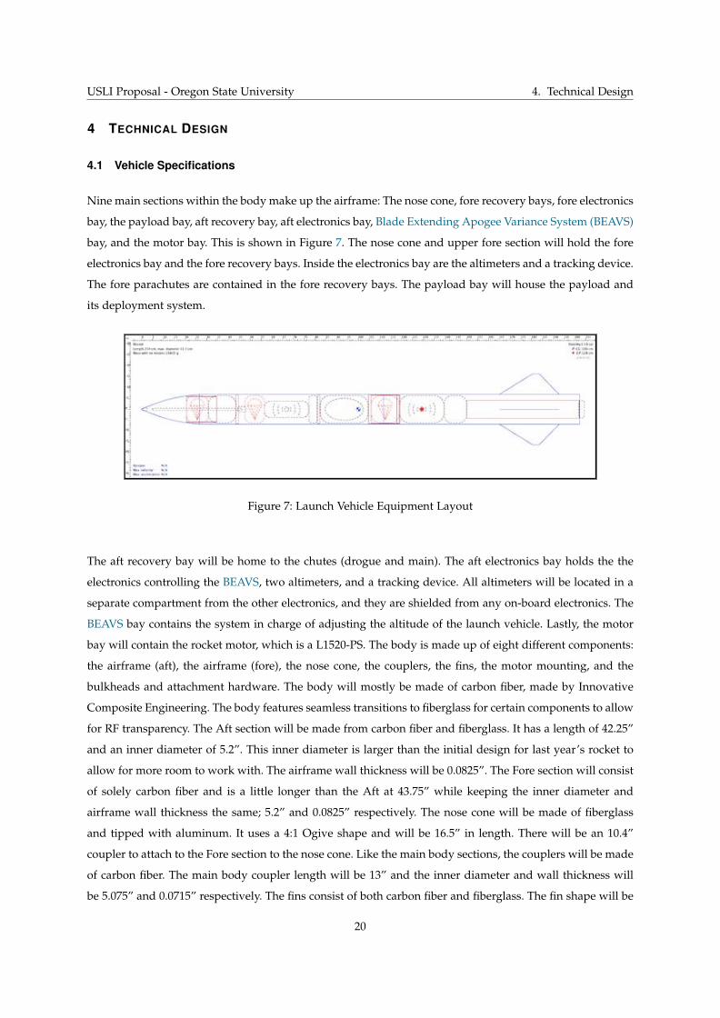
Nine main sections within the body make up the airframe: The nose cone, fore recovery bays, fore electronics
bay, the payload bay, aft recovery bay, aft electronics bay, Blade Extending Apogee Variance System (BEAVS)
bay, and the motor bay. This is shown in Figure 7. The nose cone and upper fore section will hold the fore
electronics bay and the fore recovery bays. Inside the electronics bay are the altimeters and a tracking device.
The fore parachutes are contained in the fore recovery bays. The payload bay will house the payload and
its deployment system.
Figure 7: Launch Vehicle Equipment Layout
The aft recovery bay will be home to the chutes (drogue and main). The aft electronics bay holds the the
electronics controlling the BEAVS, two altimeters, and a tracking device. All altimeters will be located in a
separate compartment from the other electronics, and they are shielded from any on-board electronics. The
BEAVS bay contains the system in charge of adjusting the altitude of the launch vehicle. Lastly, the motor
bay will contain the rocket motor, which is a L1520-PS. The body is made up of eight different components:
the airframe (aft), the airframe (fore), the nose cone, the couplers, the fins, the motor mounting, and the
bulkheads and attachment hardware. The body will mostly be made of carbon fiber, made by Innovative
Composite Engineering. The body features seamless transitions to fiberglass for certain components to allow
for RF transparency. The Aft section will be made from carbon fiber and fiberglass. It has a length of 42.25”
and an inner diameter of 5.2”. This inner diameter is larger than the initial design for last year’s rocket to
allow for more room to work with. The airframe wall thickness will be 0.0825”. The Fore section will consist
of solely carbon fiber and is a little longer than the Aft at 43.75” while keeping the inner diameter and
airframe wall thickness the same; 5.2” and 0.0825” respectively. The nose cone will be made of fiberglass
and tipped with aluminum. It uses a 4:1 Ogive shape and will be 16.5” in length. There will be an 10.4”
coupler to attach to the Fore section to the nose cone. Like the main body sections, the couplers will be made
of carbon fiber. The main body coupler length will be 13” and the inner diameter and wall thickness will
be 5.075” and 0.0715” respectively. The fins consist of both carbon fiber and fiberglass. The fin shape will be
20
USLI Proposal - Oregon State University 4.1 Vehicle Specifications
Clipped Delta and there will be four of them. The design for the motor mounting consists of three centering
rings. The motor mounting tube and aft retainer will secure the motor within the Aft. The bulkheads will be
made of plywood with a thickness of 0.4605”. The outer diameter will be 5.2” and there will be a 0.5” hole
drilled directly through the center of the bulkhead. Lastly, the attachment hardware consists of a locknut,
eye nut, and a washer. This component is for parachute quick links. These materials were chosen for specific
components because they have shown to be sufficient in other OSRT endeavors, including the 2017-2018
OSRT launch vehicle.
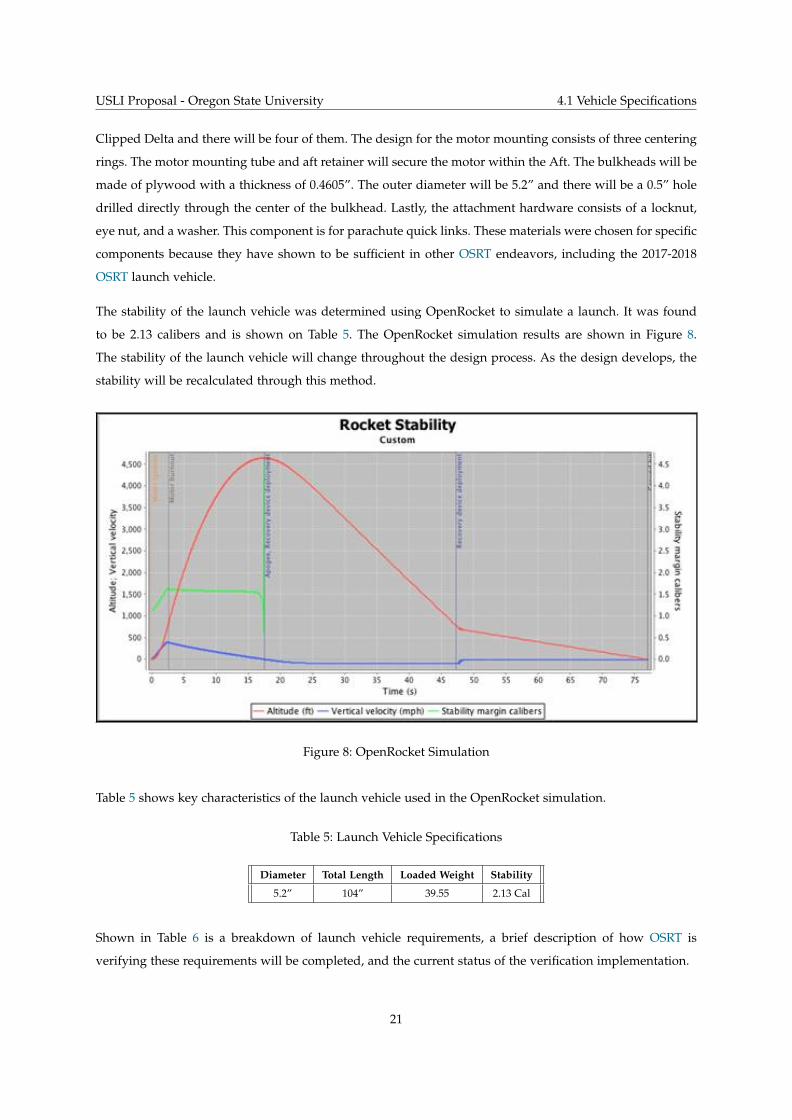
The stability of the launch vehicle was determined using OpenRocket to simulate a launch. It was found
to be 2.13 calibers and is shown on Table 5. The OpenRocket simulation results are shown in Figure 8.
The stability of the launch vehicle will change throughout the design process. As the design develops, the
stability will be recalculated through this method.
Figure 8: OpenRocket Simulation
Table 5 shows key characteristics of the launch vehicle used in the OpenRocket simulation.
Table 5: Launch Vehicle Specifications
Diameter Total Length Loaded Weight Stability
5.2” 104” 39.55 2.13 Cal
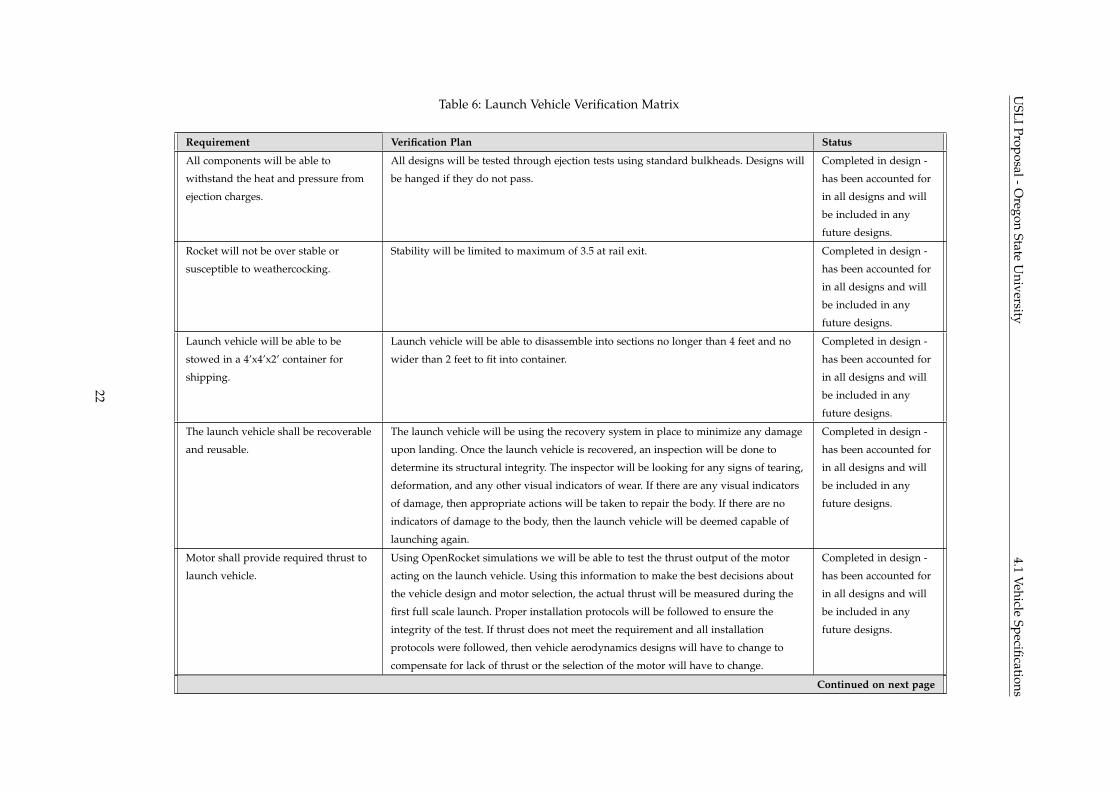
Shown in Table 6 is a breakdown of launch vehicle requirements, a brief description of how OSRT is
verifying these requirements will be completed, and the current status of the verification implementation.
21
USLI
Proposal-Oregon
StateU
niversity4.1
VehicleSpecifications
Table 6: Launch Vehicle Verification Matrix
Requirement Verification Plan Status
All components will be able to
withstand the heat and pressure from
ejection charges.
All designs will be tested through ejection tests using standard bulkheads. Designs will
be hanged if they do not pass.
Completed in design -
has been accounted for
in all designs and will
be included in any
future designs.
Rocket will not be over stable or
susceptible to weathercocking.
Stability will be limited to maximum of 3.5 at rail exit. Completed in design -
has been accounted for
in all designs and will
be included in any
future designs.
Launch vehicle will be able to be
stowed in a 4’x4’x2’ container for
shipping.
Launch vehicle will be able to disassemble into sections no longer than 4 feet and no
wider than 2 feet to fit into container.
Completed in design -
has been accounted for
in all designs and will
be included in any
future designs.
The launch vehicle shall be recoverable
and reusable.
The launch vehicle will be using the recovery system in place to minimize any damage
upon landing. Once the launch vehicle is recovered, an inspection will be done to
determine its structural integrity. The inspector will be looking for any signs of tearing,
deformation, and any other visual indicators of wear. If there are any visual indicators
of damage, then appropriate actions will be taken to repair the body. If there are no
indicators of damage to the body, then the launch vehicle will be deemed capable of
launching again.
Completed in design -
has been accounted for
in all designs and will
be included in any
future designs.
Motor shall provide required thrust to
launch vehicle.
Using OpenRocket simulations we will be able to test the thrust output of the motor
acting on the launch vehicle. Using this information to make the best decisions about
the vehicle design and motor selection, the actual thrust will be measured during the
first full scale launch. Proper installation protocols will be followed to ensure the
integrity of the test. If thrust does not meet the requirement and all installation
protocols were followed, then vehicle aerodynamics designs will have to change to
compensate for lack of thrust or the selection of the motor will have to change.
Completed in design -
has been accounted for
in all designs and will
be included in any
future designs.
Continued on next page
22
USLI
Proposal-Oregon
StateU
niversity4.1
VehicleSpecifications
Table 6 – continued from previous page
Requirement Verification Plan Status
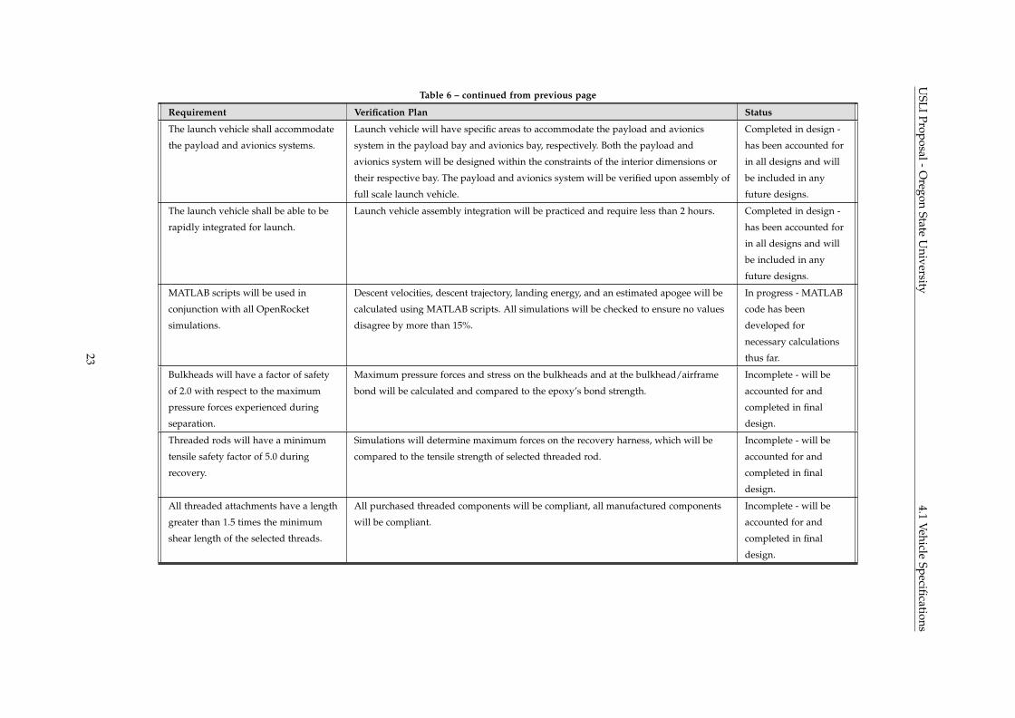
The launch vehicle shall accommodate
the payload and avionics systems.
Launch vehicle will have specific areas to accommodate the payload and avionics
system in the payload bay and avionics bay, respectively. Both the payload and
avionics system will be designed within the constraints of the interior dimensions or
their respective bay. The payload and avionics system will be verified upon assembly of
full scale launch vehicle.
Completed in design -
has been accounted for
in all designs and will
be included in any
future designs.
The launch vehicle shall be able to be
rapidly integrated for launch.
Launch vehicle assembly integration will be practiced and require less than 2 hours. Completed in design -
has been accounted for
in all designs and will
be included in any
future designs.
MATLAB scripts will be used in
conjunction with all OpenRocket
simulations.
Descent velocities, descent trajectory, landing energy, and an estimated apogee will be
calculated using MATLAB scripts. All simulations will be checked to ensure no values
disagree by more than 15%.
In progress - MATLAB
code has been
developed for
necessary calculations
thus far.
Bulkheads will have a factor of safety
of 2.0 with respect to the maximum
pressure forces experienced during
separation.
Maximum pressure forces and stress on the bulkheads and at the bulkhead/airframe
bond will be calculated and compared to the epoxy’s bond strength.
Incomplete - will be
accounted for and
completed in final
design.
Threaded rods will have a minimum
tensile safety factor of 5.0 during
recovery.
Simulations will determine maximum forces on the recovery harness, which will be
compared to the tensile strength of selected threaded rod.
Incomplete - will be
accounted for and
completed in final
design.
All threaded attachments have a length
greater than 1.5 times the minimum
shear length of the selected threads.
All purchased threaded components will be compliant, all manufactured components
will be compliant.
Incomplete - will be
accounted for and
completed in final
design.
23
USLI Proposal - Oregon State University 4.2 Projected Altitude
4.2 Projected Altitude
An OpenRocket simulation was performed to calculate a projected altitude of the OSRT launch vehicle.
Simulations were performed for different cross wind speeds, with a maximum projected altitude of 4,639
feet with no cross winds. With 5 mph wind speeds projected altitude is 4,637 feet. At 10 mph, the projected
altitude of the launch vehicle is 4,635 feet, and decreases to 4,612 feet with a wind speed of 15 mph. The
maximum simulation wind speed was 20 mph, giving a projected altitude of 4,530 feet. The projected
altitudes assume there is no ballast and no changes to the drag profile of the rocket during flight. The
projected altitudes were calculated at an angle of launch at zero degrees. Factoring in a launch angle can
greatly decrease the projected altitudes but also may decrease horizontal distance traveled on decent due
to cross-winds. The data collected in the OpenRocket simulation will be verified in subscale test launches,
prior to the full scale launch day. Additional aerodynamic analysis will be performed using RASAero II to
verify the OpenRocket simulation. Wind speeds will be monitored as launch day approaches. OSRT has
decided to target 4,500 feet as a desired apogee altitude.
4.2.1 Projected Altitude Adjustment
The BEAVS will be used to control the exact apogee altitude of the launch vehicle despite variances in
launch day conditions such as wind. This system uses two different subsystems to control apogee altitude:
a passive and an active system. The passive BEAVS system is a coupled pair of ballast bays. These ballast
bays are separated into the fore and aft sections, one below and one above the center of gravity. The mass
contained within these ballast bays can be easily adjusted which will result in a consistent center of gravity
location. A consistent center of gravity location is beneficial because it will allow for the launch vehicle to
maintain the same stability while changing the amount of ballast. The active system will adjust the drag
profile of the launch vehicle during flight to achieve the desired apogee altitude. OSRT plans to use the
BEAVS to target an altitude within 50 feet of the planned target altitude.
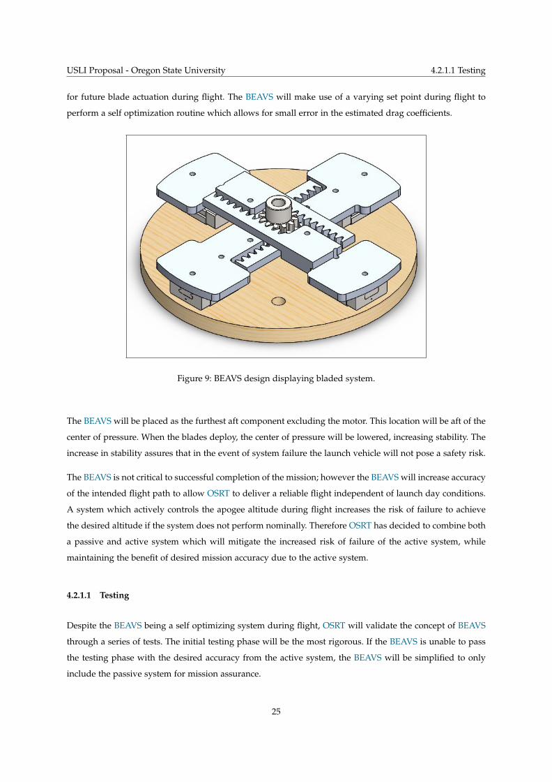
This system will include blades which remain inside of the launch vehicle during motor burn, as shown
in Figure 9. Upon motor burnout, blades which are perpendicular to the airframe can be deployed si-
multaneously, increasing the drag force on the launch vehicle. After motor burnout, drag and gravity are
the only forces present on the launch vehicle. The BEAVS can accurately determine the position, velocity,
acceleration, and angle of attack of the launch vehicle during flight, known as the current state. Based on
the current state, BEAVS will then estimate apogee altitude by using these characteristics in a numerical
method with a small time step. Based on the drag coefficient with blades extended and the calculated
apogee altitude, the BEAVS can calculate the duration the blades should be extended from the airframe to
achieve a desired apogee altitude. After the blades are retracted into the airframe, the BEAVS will calculate
the new expected apogee altitude, and determine the error between the newly calculated apogee altitude
and the desired apogee altitude. This value will be used to modify the drag coefficient of the launch vehicle
24
USLI Proposal - Oregon State University 4.2.1.1 Testing
for future blade actuation during flight. The BEAVS will make use of a varying set point during flight to
perform a self optimization routine which allows for small error in the estimated drag coefficients.
Figure 9: BEAVS design displaying bladed system.
The BEAVS will be placed as the furthest aft component excluding the motor. This location will be aft of the
center of pressure. When the blades deploy, the center of pressure will be lowered, increasing stability. The
increase in stability assures that in the event of system failure the launch vehicle will not pose a safety risk.
The BEAVS is not critical to successful completion of the mission; however the BEAVS will increase accuracy
of the intended flight path to allow OSRT to deliver a reliable flight independent of launch day conditions.
A system which actively controls the apogee altitude during flight increases the risk of failure to achieve
the desired altitude if the system does not perform nominally. Therefore OSRT has decided to combine both
a passive and active system which will mitigate the increased risk of failure of the active system, while
maintaining the benefit of desired mission accuracy due to the active system.
4.2.1.1 Testing
Despite the BEAVS being a self optimizing system during flight, OSRT will validate the concept of BEAVS
through a series of tests. The initial testing phase will be the most rigorous. If the BEAVS is unable to pass
the testing phase with the desired accuracy from the active system, the BEAVS will be simplified to only
include the passive system for mission assurance.
25
USLI Proposal - Oregon State University 4.2.1.2 Mechanical System
The testing will take place on a Mad Dog DD fiberglass airframe which has 4” body diameter. This airframe
was selected due to its availability to the OSRT: it was used as the 2017-2018 OSRT subscale launch vehicle.
Some modifications to the airframe will be required to prepare it for testing of the BEAVS. It will, however,
allow OSRT to begin testing the system as early as possible. OSRT plans to test the BEAVS on at least 3
flights in the Mad Dog DD launch vehicle before the active system is integrated into the full scale launch
vehicle. Once integrated into the full scale launch vehicle, the BEAVS will undergo additional testing to
ensure it maintains performance in the new airframe. The rigorous and continuous testing of the BEAVS
will allow OSRT to provide an additional level of mission assurance by proving reliability of the active
portion of the BEAVS.
In addition to the testing of the active portion of the BEAVS, the passive portion of the BEAVS must be
tested in all potential ballasted conditions prior to launch at the USLI competition. The BEAVS will be
tested with at minimum 3 ballast configurations, sized for wind conditions of 0 mph, 10 mph, and 20 mph.
The ballast will be a modular stack of steel weights in each bay which are secured through the use of two
1/4-20 fasteners, allowing for the exact weight to be modified on test launch days. The aft ballast bay will be
located fore of the active system. The fore ballast bay will be located at the hard point on the fore section
of the airframe. While the modularity is beneficial for testing purposes, OSRT notes that the exact ballast
configuration used at competition must be successfully tested previously.
4.2.1.2 Mechanical System
The BEAVS will extend 4 blades through slots cut into the airframe. The blades will be manufactured from
1/8” aluminum plate using a CNC mill. The blades will attach to a linear bearing on a 7 millimeter guide
rail with three M2 fasteners. The blades will have a set of teeth which create a rack and pinion system with
a central drive gear. The central drive gear will operate all four fins simultaneously. The linear bearings will
be mounted to a removable bulkhead made of 1/2” aerospace grade plywood. The bulkhead will be just fore
of the motor casing, and will provide the structure for how the system is retained within the launch vehicle.
Four 8-32 threaded rods will extend through the bulkhead towards the fore section of the launch vehicle.
These four threaded rods will tie into a bulkhead on the fore side of BEAVS with nylon lock nuts, which will
serve as the attachment point for the aft electronics bay. A National Electrical Manufacturers Association
(NEMA) 23 stepper motor will be directly attached to the central drive gear. Fore of the NEMA 23 stepper
motor will be a custom designed and Fused Deposition Modeling (FDM) 3D printed compartment out
of Polylactic Acid (PLA) for the electronic systems used to control the stepper motor, and will be the
compartment which stores the aft ballast weights of the BEAVS. The fore ballast bay will be located on the
fore section hard point.
The blades were designed to account for a 32.0% increase cross sectional area of the test launch vehicle. Due
to the self optimizing control scheme, the 32.0% increase in the cross sectional area was used to approximate
26
USLI Proposal - Oregon State University 4.2.1.3 Electrical System
a drag coefficient of the launch vehicle by acting as a direct multiplier of the drag coefficient before
deployment. The test launch vehicle being flown has a drag coefficient of approximately 0.51 according
to OpenRocket simulations, therefore when the blades are fully deployed it is estimated that the drag
coefficient is 0.67. This is expected to be a conservative estimate, due to fluid flow separation effects when
the blades are extended from the airframe. OSRT is currently developing a Computational Fluid Dynamics
(CFD) simulation in STAR-CCM+ which will provide a more accurate result for the drag coefficient with
and without blade deployment. Due to the self optimizing nature of the BEAVS control system, there is
allowable error within the drag coefficient to still achieve desired performance of the system.
4.2.1.3 Electrical System
The BEAVS will consist of a Printed Circuit Board (PCB) which is designed by OSRT and consists of
a Nine Degree of Freedom (9DOF) accelerometer, a barometric pressure sensor, a motor driver, and a
microcontroller. The software for the BEAVS will be written in C/C++ to control the sensor data acquisition
and filter the data. The data will be filtered using a Kalman filter to reduce the effects of noise in the
measurements. The filtered data will then be used to predict apogee altitude based on current flight
characteristics. Based off of the predicted apogee altitude, the PCB will send a signal to a motor driver
which will be used to control the exact position of the blades during flight.
4.2.1.4 Control System
The BEAVS will have a control scheme which is reliant on a varying set point to provide in-flight opti-
mization. The control system has been reduced to a 1 degree of freedom control system, where the control
variable is apogee altitude. The control system has only two possible states: blades retracted or blades
deployed (note: this assumes blades deploy quickly enough to be negligible). With the blades deployed, the
drag coefficient of the launch vehicle is increased, which lowers the expected apogee altitude. With blades
retracted, the expected apogee altitude does not change. Therefore, the only output of the control system
is to lower the expected apogee altitude. This presents a problem that if the control scheme overshoots the
desired apogee altitude, there is no way to recover from that error to reach the desired apogee altitude.
OSRT broke this problem down into two different ways which the problem could be solved.
The first solution is the more traditional control method which OSRT was familiar with, designing a
Proportional-Integral-Derivative (PID) control loop and optimizing the parameters through testing in order
to find PID coefficients such that the system is critically damped. This method presented a large flaw: the
best way to test these parameters is to fly the launch vehicle and analyze the results of the test numerous
times. This is expensive per test, and may require more test flights than OSRT can reasonably conduct before
the competition.
27

USLI Proposal - Oregon State University 4.3 Recovery System
The next option which OSRT looked at was to use a varying set point control scheme. In this control
scheme, the desired apogee altitude value after blade deployment changes during flight. The set point
is to be reduced through a number of steps that gradually approach the overall desired apogee altitude
value. After each blade deployment cycle, the PID parameters are updated based on the error between the
set point and the expected apogee altitude. This method drastically reduces the number of tests required
to dial in the PID parameters of the control system. The self optimizing control scheme will utilize only
proportional control during initial testing of the BEAVS for simplicity. If it is determined to be necessary to
achieve desired accuracy, integral and derivative control can be added in at a later date.
The proportional control will be achieved through duty cycle adjustment. A duty cycle of 1 second will
be utilized, with the blade deployment time required to reach the set point being a percentage of the
duty cycle. The percentage of the duty cycle will be multiplied by the proportional control parameter to
determine actual blade deployment time. Based on the 2017-2018 OSRT flight data, BEAVS should have at
least 10 duty cycles to be completed during flight.
4.3 Recovery System
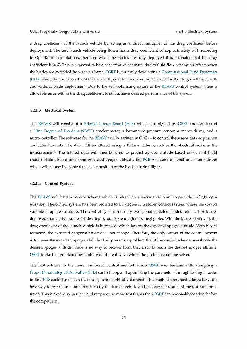
4.3.1 Separation Events and Descent
The recovery system will consist of two dual deployment systems. At apogee, two ejection charges contain-
ing a predetermined amount of black powder will be ignited with electronic matches. One of the charges,
located centrally in the launch vehicle, will separate the launch vehicle into two independent sections: fore
and aft. The other charge, located in the fore section, will separate the fore section of the airframe from
the nose cone. Immediately following the apogee separation event, a drogue parachute is released from
each independent section of the launch vehicle. The drogue parachutes will control the descent velocity and
provide stability to the launch vehicle. At 600 feet AGL, both main parachutes will be released, allowing all
sections to land under the required 75 foot pounds of kinetic energy. The projected flight is seen in Figure
10.
28
USLI Proposal - Oregon State University 4.3.2 Altimeters
Figure 10: Launch Vehicle Flight (not drawn to scale).
4.3.2 Altimeters
MissileWorks Rocket Recovery Controller 3 (RRC3) and PerfectFlite StratoLogger CF altimeters will be used
to set off ejection charges and record the altitude. Both of these altimeters have excellent reliability. These
altimeters also have an excellent track record at Oregon State, as they have been used previously by OSRT
and have had minimal issues. Both brands of altimeters calculate altitude and apogee using barometric
sensors. The main altimeters will be RRC3, and the secondary altimeters will be StratoLogger CF. Two of
each will be used: one of each in the fore and aft sections. The reason to have two different altimeters is for
redundancy. If one fails due to a defect, having a backup of a different brand will eliminate the chances of
total failure due to a batch defect.
4.3.2.1 Accurate Pressure Readings
In order for a barometric altimeter to work correctly, it must be vented to the outside air. Static port holes
will be located so there are no obstructions forward of them, and they will also be placed on the altimeter
bays. Additionally, on the fore altimeter bay, the static port holes will be placed as far aft of the nose cone as
possible while still being located on the bay. Following MissileWorks recommendations for port hole sizing,
the altimeter bay volume in inches cubed divided by 400 equals the port hole diameter in inches. If the port
29
USLI Proposal - Oregon State University 4.3.2.2 Number of Static Port Holes
hole diameter ends up being relatively large, such as larger than 3/4”, three static port holes of one third the
diameter will be used for each altimeter bay.
4.3.2.2 Number of Static Port Holes
Sizing of the altimeter bays will be very important - having static port holes which are too large or too small
can cause early or late deployment of parachutes, respectively. The proposed launch vehicle diameter is 5.2
inches. If the maximum diameter chosen for static port holes were to be .75 inches, then the altimeter bays
would need to be shorter than 14.1 inches. If the bays were longer than 14.1 inches, more than one static
port hole should be used.
4.3.2.3 Backup Charges
Ejection charges are used to separate the nose cone from the fore section, the fore altimeter bay from the
fore section, and the fore section from the aft section. For each separation event, two charges will be used.
For the release of the aft main parachute, two Tender Descenders will be connected in series. Each Tender
Descender will have one charge inside of it. Every altimeter will ignite two charges: the fore altimeters are in
charge of the separation events, while the aft are in charge of separation and release of Tender Descenders.
Backup separation charges will be ignited one second after primary charges in order to stay within the two
second maximum delay at apogee, assuming the first charges fail, and to avoid overpressurization of the
launch vehicle due to simultaneous ignition.
4.3.3 Parachutes and Retention
Both aft parachutes are located centrally in the launch vehicle, and both fore parachutes are located between
the upper body tube and the nose cone.
4.3.3.1 Fore Parachutes
The fore parachutes will be secured to one bulkhead and one end of the fore altimeter bay each. One
bulkhead is located in the nose cone and one is located in the fore section. The fore bulkhead will have one
short, threaded rod ran through it. The end the main parachute is secured to will have an eye nut threaded
onto the rod, as well as a locking nut, to ensure the eye nut does not twist off. The opposite end will have
a standard nut, securing the rod in place. The nose cone bulkhead will have one threaded rod with an eye
nut and regular nut threaded onto it in the same fashion as the fore bulkhead. The fore altimeter bay will
have an eye bolt on both sides. The drogue parachute will be harnessed to the nylon shock cord, which is
connected to the nose cone and the fore end of the altimeter bay. The shock cord will be attached to the eye
30
USLI Proposal - Oregon State University 4.3.3.2 Aft Parachutes
nut with a quick link. The main parachute will have two attachment points: the eye nut in the fore bulkhead
and the eye bolt connected to the aft end of the altimeter bay. Both will have a long section of nylon shock
cord attached to quick links, which are attached to the eye nuts in the bulkheads. The charges separating
the fore altimeter bay from the fore section are ignited at 600 feet AGL, allowing the main parachute to
be pulled out. Each harness and shock cord attached to an eye nut or bolt will have a quick link between
them. All quick links will be rated at 880 pounds for static load. Each section of shock cord attached to a
parachute will have the same quick links used everywhere else, as well as a swivel, rated at 1000 pounds
static load, to allow the parachutes to rotate freely.
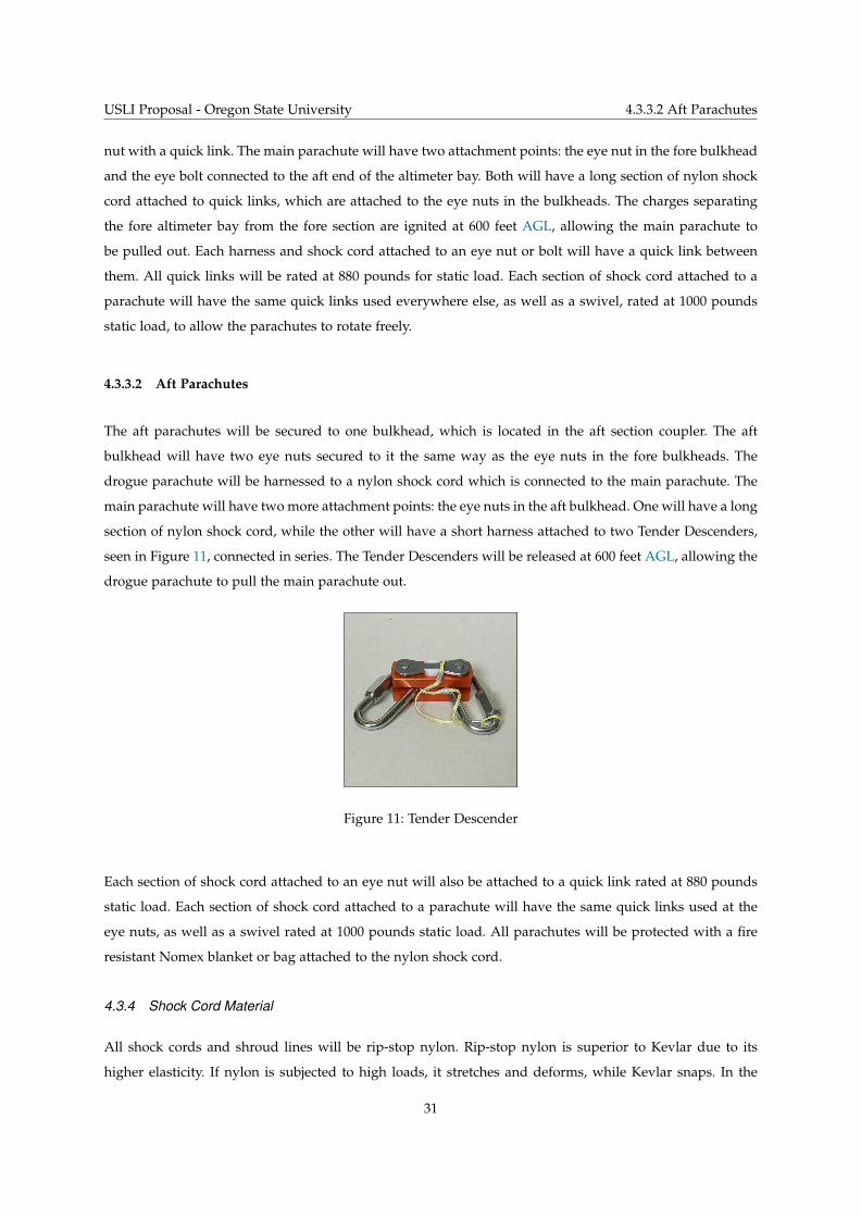
4.3.3.2 Aft Parachutes
The aft parachutes will be secured to one bulkhead, which is located in the aft section coupler. The aft
bulkhead will have two eye nuts secured to it the same way as the eye nuts in the fore bulkheads. The
drogue parachute will be harnessed to a nylon shock cord which is connected to the main parachute. The
main parachute will have two more attachment points: the eye nuts in the aft bulkhead. One will have a long
section of nylon shock cord, while the other will have a short harness attached to two Tender Descenders,
seen in Figure 11, connected in series. The Tender Descenders will be released at 600 feet AGL, allowing the
drogue parachute to pull the main parachute out.
Figure 11: Tender Descender
Each section of shock cord attached to an eye nut will also be attached to a quick link rated at 880 pounds
static load. Each section of shock cord attached to a parachute will have the same quick links used at the
eye nuts, as well as a swivel rated at 1000 pounds static load. All parachutes will be protected with a fire
resistant Nomex blanket or bag attached to the nylon shock cord.
4.3.4 Shock Cord Material
All shock cords and shroud lines will be rip-stop nylon. Rip-stop nylon is superior to Kevlar due to its
higher elasticity. If nylon is subjected to high loads, it stretches and deforms, while Kevlar snaps. In the
31
USLI Proposal - Oregon State University 4.3.5 Parachute Shielding
event of extreme snatch loads, Kevlar could fail, while nylon would stretch, helping dissipate the load. The
nylon will be 9/16 inches in width to avoid zippering of the airframe. The length of the main parachute
shock cords will be three times the length of their respective body sections, while the drogue shock cords
will be at least two times the length of their respective body sections.
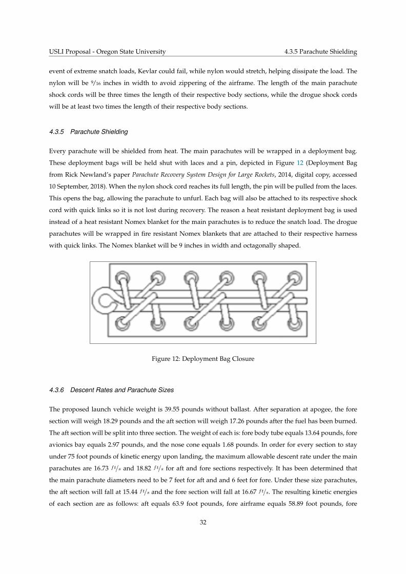
4.3.5 Parachute Shielding
Every parachute will be shielded from heat. The main parachutes will be wrapped in a deployment bag.
These deployment bags will be held shut with laces and a pin, depicted in Figure 12 (Deployment Bag
from Rick Newland’s paper Parachute Recovery System Design for Large Rockets, 2014, digital copy, accessed
10 September, 2018). When the nylon shock cord reaches its full length, the pin will be pulled from the laces.
This opens the bag, allowing the parachute to unfurl. Each bag will also be attached to its respective shock
cord with quick links so it is not lost during recovery. The reason a heat resistant deployment bag is used
instead of a heat resistant Nomex blanket for the main parachutes is to reduce the snatch load. The drogue
parachutes will be wrapped in fire resistant Nomex blankets that are attached to their respective harness
with quick links. The Nomex blanket will be 9 inches in width and octagonally shaped.
Figure 12: Deployment Bag Closure
4.3.6 Descent Rates and Parachute Sizes
The proposed launch vehicle weight is 39.55 pounds without ballast. After separation at apogee, the fore
section will weigh 18.29 pounds and the aft section will weigh 17.26 pounds after the fuel has been burned.
The aft section will be split into three section. The weight of each is: fore body tube equals 13.64 pounds, fore
avionics bay equals 2.97 pounds, and the nose cone equals 1.68 pounds. In order for every section to stay
under 75 foot pounds of kinetic energy upon landing, the maximum allowable descent rate under the main
parachutes are 16.73 ft/s and 18.82 ft/s for aft and fore sections respectively. It has been determined that
the main parachute diameters need to be 7 feet for aft and and 6 feet for fore. Under these size parachutes,
the aft section will fall at 15.44 ft/s and the fore section will fall at 16.67 ft/s. The resulting kinetic energies
of each section are as follows: aft equals 63.9 foot pounds, fore airframe equals 58.89 foot pounds, fore
32
USLI Proposal - Oregon State University 4.3.6 Descent Rates and Parachute Sizes
avionics bay equals 12.82 foot pounds, and the nose cone equals 7.25 foot pounds. The shape used for the
main parachutes will be toroidal, because of the increased drag the shape offers. This allows for smaller
parachutes and smaller packing volume with the same descent rate as an elliptical parachute would offer.
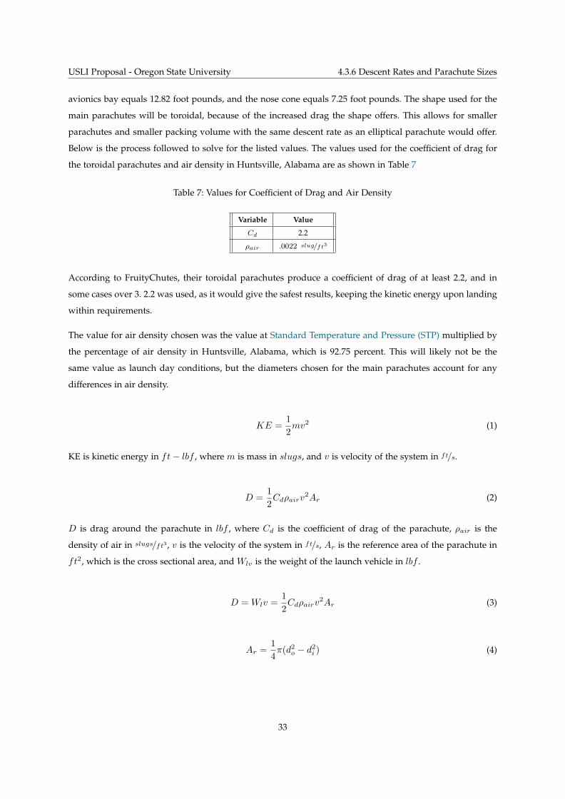
Below is the process followed to solve for the listed values. The values used for the coefficient of drag for
the toroidal parachutes and air density in Huntsville, Alabama are as shown in Table 7
Table 7: Values for Coefficient of Drag and Air Density
Variable Value
Cd 2.2
ρair .0022 slug/ft3
According to FruityChutes, their toroidal parachutes produce a coefficient of drag of at least 2.2, and in
some cases over 3. 2.2 was used, as it would give the safest results, keeping the kinetic energy upon landing
within requirements.
The value for air density chosen was the value at Standard Temperature and Pressure (STP) multiplied by
the percentage of air density in Huntsville, Alabama, which is 92.75 percent. This will likely not be the
same value as launch day conditions, but the diameters chosen for the main parachutes account for any
differences in air density.
KE =1
2mv2 (1)
KE is kinetic energy in ft− lbf , where m is mass in slugs, and v is velocity of the system in ft/s.
D =1
2Cdρairv
2Ar (2)
D is drag around the parachute in lbf , where Cd is the coefficient of drag of the parachute, ρair is the
density of air in slugs/ft3, v is the velocity of the system in ft/s, Ar is the reference area of the parachute in
ft2, which is the cross sectional area, and Wlv is the weight of the launch vehicle in lbf .
D =Wlv =1
2Cdρairv
2Ar (3)
Ar =1
4π(d2o − d2i ) (4)
33
USLI Proposal - Oregon State University 4.3.7 Couplers and Shear Pins
The reference area can be defined in terms of the outer and inner diameters of the toroidal parachute, where
do is the outer diameter and di is the inner diameter. Typically, the ratio between outer and inner diameters
for this shape of parachute is 5:1. Using this, the reference area equation becomes:
Ar =6
25πd2o (5)
Plugging equation 5 into equation 2 and solving for the outer diameter gives:
do =
√25Wlv
3πρairCdv2(6)
The drogue parachutes chosen are cruciform shape. The diameter of the parachutes are 2.33 ft. With a
coefficient of drag of about 0.9, the fore and aft sections will fall at 72.87 ft/s and 70.79 ft/s respectively.
4.3.7 Couplers and Shear Pins
The launch vehicle will contain two couplers: one attaching the nose cone to the fore section, and one
attaching the fore section to the aft section. The fore coupler will be permanently fixed to the nose cone, and
it will fit snugly inside the fore section of the launch vehicle. The aft coupler will be permanently fixed to
the aft section, and it will fit snugly inside the fore section. The aft coupler will be 2.5 times the diameter of
the launch vehicle in length, which is 13 inches, and the fore coupler will be two times the launch vehicle
length, which is 10.4 inches. In order to keep the pieces of the launch vehicle intact during the ascent, nylon
2-56 x 1/4′′ shear pins will be used to temporarily hold each section together. These pins will shear when
under too much pressure. In order to ensure separation, a slight excess of black powder will be used in each
ejection charge. Ground testing will be done to ensure at least three complete separations of sections after
ignition of ejection charges.
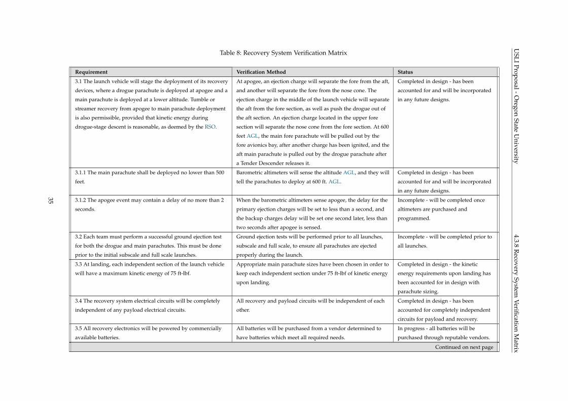
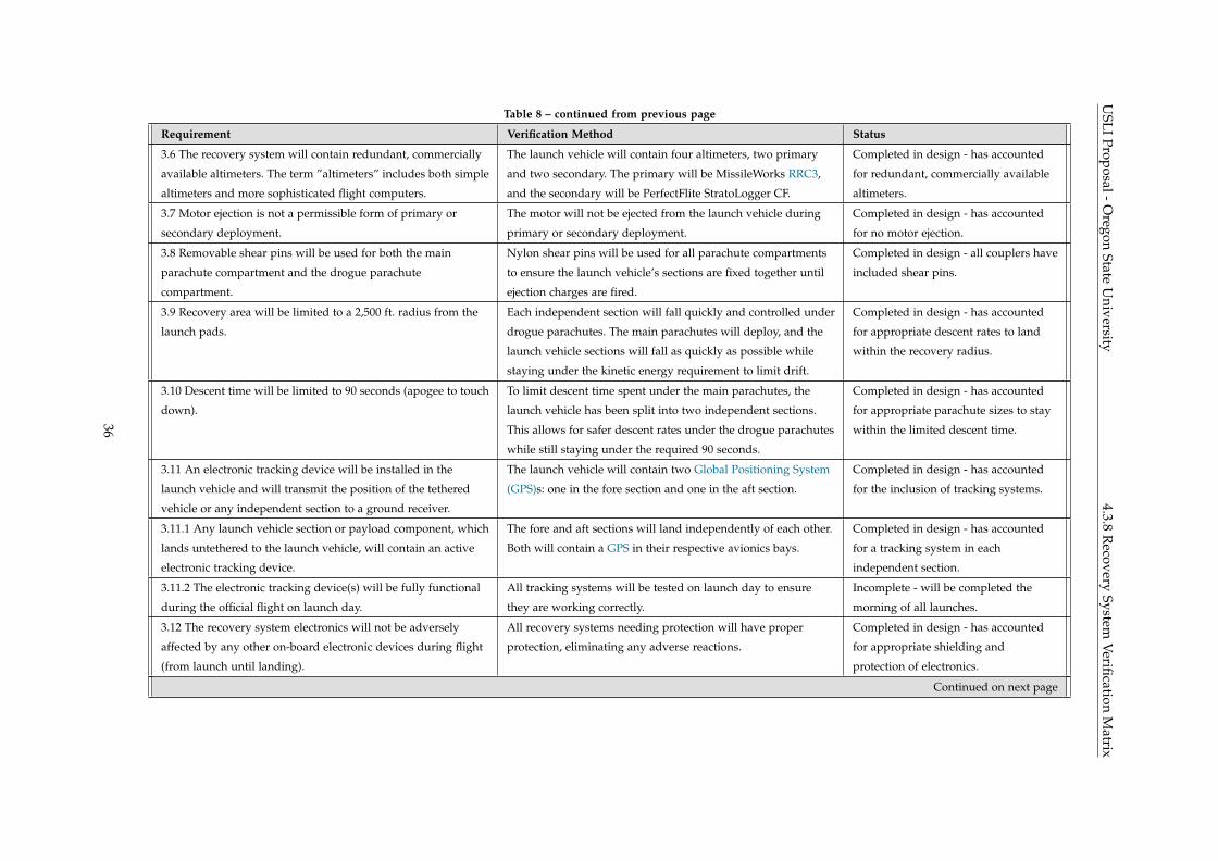
4.3.8 Recovery System Verification Matrix
Shown in Table 8 is a breakdown of recovery system requirements, a brief description of how OSRT is
verifying these requirements will be completed, and the current status of the verification implementation.
34
USLI
Proposal-Oregon
StateU
niversity4.3.8
Recovery
SystemVerification
Matrix
Table 8: Recovery System Verification Matrix
Requirement Verification Method Status
3.1 The launch vehicle will stage the deployment of its recovery
devices, where a drogue parachute is deployed at apogee and a
main parachute is deployed at a lower altitude. Tumble or
streamer recovery from apogee to main parachute deployment
is also permissible, provided that kinetic energy during
drogue-stage descent is reasonable, as deemed by the RSO.
At apogee, an ejection charge will separate the fore from the aft,
and another will separate the fore from the nose cone. The
ejection charge in the middle of the launch vehicle will separate
the aft from the fore section, as well as push the drogue out of
the aft section. An ejection charge located in the upper fore
section will separate the nose cone from the fore section. At 600
feet AGL, the main fore parachute will be pulled out by the
fore avionics bay, after another charge has been ignited, and the
aft main parachute is pulled out by the drogue parachute after
a Tender Descender releases it.
Completed in design - has been
accounted for and will be incorporated
in any future designs.
3.1.1 The main parachute shall be deployed no lower than 500
feet.
Barometric altimeters will sense the altitude AGL, and they will
tell the parachutes to deploy at 600 ft. AGL.
Completed in design - has been
accounted for and will be incorporated
in any future designs.
3.1.2 The apogee event may contain a delay of no more than 2
seconds.
When the barometric altimeters sense apogee, the delay for the
primary ejection charges will be set to less than a second, and
the backup charges delay will be set one second later, less than
two seconds after apogee is sensed.
Incomplete - will be completed once
altimeters are purchased and
programmed.
3.2 Each team must perform a successful ground ejection test
for both the drogue and main parachutes. This must be done
prior to the initial subscale and full scale launches.
Ground ejection tests will be performed prior to all launches,
subscale and full scale, to ensure all parachutes are ejected
properly during the launch.
Incomplete - will be completed prior to
all launches.
3.3 At landing, each independent section of the launch vehicle
will have a maximum kinetic energy of 75 ft-lbf.
Appropriate main parachute sizes have been chosen in order to
keep each independent section under 75 ft-lbf of kinetic energy
upon landing.
Completed in design - the kinetic
energy requirements upon landing has
been accounted for in design with
parachute sizing.
3.4 The recovery system electrical circuits will be completely
independent of any payload electrical circuits.
All recovery and payload circuits will be independent of each
other.
Completed in design - has been
accounted for completely independent
circuits for payload and recovery.
3.5 All recovery electronics will be powered by commercially
available batteries.
All batteries will be purchased from a vendor determined to
have batteries which meet all required needs.
In progress - all batteries will be
purchased through reputable vendors.
Continued on next page
35
USLI
Proposal-Oregon
StateU
niversity4.3.8
Recovery
SystemVerification
Matrix
Table 8 – continued from previous page
Requirement Verification Method Status
3.6 The recovery system will contain redundant, commercially
available altimeters. The term ”altimeters” includes both simple
altimeters and more sophisticated flight computers.
The launch vehicle will contain four altimeters, two primary
and two secondary. The primary will be MissileWorks RRC3,
and the secondary will be PerfectFlite StratoLogger CF.
Completed in design - has accounted
for redundant, commercially available
altimeters.
3.7 Motor ejection is not a permissible form of primary or
secondary deployment.
The motor will not be ejected from the launch vehicle during
primary or secondary deployment.
Completed in design - has accounted
for no motor ejection.
3.8 Removable shear pins will be used for both the main
parachute compartment and the drogue parachute
compartment.
Nylon shear pins will be used for all parachute compartments
to ensure the launch vehicle’s sections are fixed together until
ejection charges are fired.
Completed in design - all couplers have
included shear pins.
3.9 Recovery area will be limited to a 2,500 ft. radius from the
launch pads.
Each independent section will fall quickly and controlled under
drogue parachutes. The main parachutes will deploy, and the
launch vehicle sections will fall as quickly as possible while
staying under the kinetic energy requirement to limit drift.
Completed in design - has accounted
for appropriate descent rates to land
within the recovery radius.
3.10 Descent time will be limited to 90 seconds (apogee to touch
down).
To limit descent time spent under the main parachutes, the
launch vehicle has been split into two independent sections.
This allows for safer descent rates under the drogue parachutes
while still staying under the required 90 seconds.
Completed in design - has accounted
for appropriate parachute sizes to stay
within the limited descent time.
3.11 An electronic tracking device will be installed in the
launch vehicle and will transmit the position of the tethered
vehicle or any independent section to a ground receiver.
The launch vehicle will contain two Global Positioning System
(GPS)s: one in the fore section and one in the aft section.
Completed in design - has accounted
for the inclusion of tracking systems.
3.11.1 Any launch vehicle section or payload component, which
lands untethered to the launch vehicle, will contain an active
electronic tracking device.
The fore and aft sections will land independently of each other.
Both will contain a GPS in their respective avionics bays.
Completed in design - has accounted
for a tracking system in each
independent section.
3.11.2 The electronic tracking device(s) will be fully functional
during the official flight on launch day.
All tracking systems will be tested on launch day to ensure
they are working correctly.
Incomplete - will be completed the
morning of all launches.
3.12 The recovery system electronics will not be adversely
affected by any other on-board electronic devices during flight
(from launch until landing).
All recovery systems needing protection will have proper
protection, eliminating any adverse reactions.
Completed in design - has accounted
for appropriate shielding and
protection of electronics.
Continued on next page
36
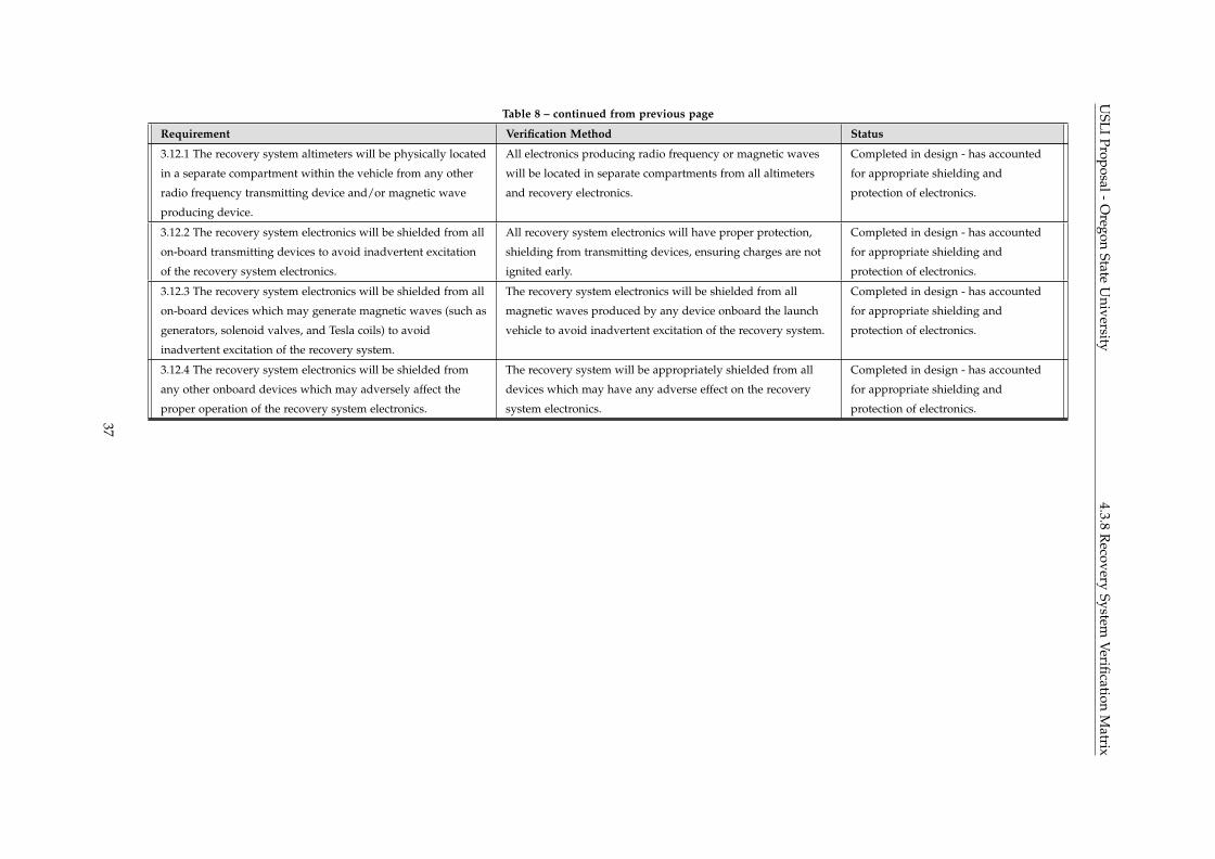
USLI
Proposal-Oregon
StateU
niversity4.3.8
Recovery
SystemVerification
Matrix
Table 8 – continued from previous page
Requirement Verification Method Status
3.12.1 The recovery system altimeters will be physically located
in a separate compartment within the vehicle from any other
radio frequency transmitting device and/or magnetic wave
producing device.
All electronics producing radio frequency or magnetic waves
will be located in separate compartments from all altimeters
and recovery electronics.
Completed in design - has accounted
for appropriate shielding and
protection of electronics.
3.12.2 The recovery system electronics will be shielded from all
on-board transmitting devices to avoid inadvertent excitation
of the recovery system electronics.
All recovery system electronics will have proper protection,
shielding from transmitting devices, ensuring charges are not
ignited early.
Completed in design - has accounted
for appropriate shielding and
protection of electronics.
3.12.3 The recovery system electronics will be shielded from all
on-board devices which may generate magnetic waves (such as
generators, solenoid valves, and Tesla coils) to avoid
inadvertent excitation of the recovery system.
The recovery system electronics will be shielded from all
magnetic waves produced by any device onboard the launch
vehicle to avoid inadvertent excitation of the recovery system.
Completed in design - has accounted
for appropriate shielding and
protection of electronics.
3.12.4 The recovery system electronics will be shielded from
any other onboard devices which may adversely affect the
proper operation of the recovery system electronics.
The recovery system will be appropriately shielded from all
devices which may have any adverse effect on the recovery
system electronics.
Completed in design - has accounted
for appropriate shielding and
protection of electronics.
37
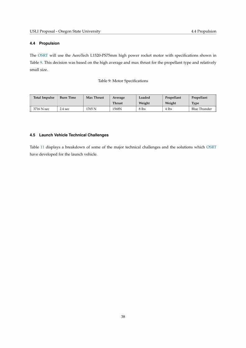
USLI Proposal - Oregon State University 4.4 Propulsion
4.4 Propulsion
The OSRT will use the AeroTech L1520-PS75mm high power rocket motor with specifications shown in
Table 9. This decision was based on the high average and max thrust for the propellant type and relatively
small size.
Table 9: Motor Specifications
Total Impulse Burn Time Max Thrust Average
Thrust
Loaded
Weight
Propellant
Weight
Propellant
Type
3716 N-sec 2.4 sec 1765 N 1568N 8 lbs 4 lbs Blue Thunder
4.5 Launch Vehicle Technical Challenges
Table 11 displays a breakdown of some of the major technical challenges and the solutions which OSRT
have developed for the launch vehicle.
38
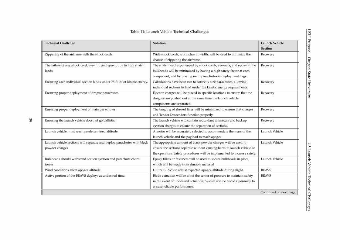
USLI
Proposal-Oregon
StateU
niversity4.5
LaunchVehicle
TechnicalChallenges
Table 11: Launch Vehicle Technical Challenges
Technical Challenge Solution Launch Vehicle
Section
Zippering of the airframe with the shock cords. Wide shock cords, 9/16 inches in width, will be used to minimize the
chance of zippering the airframe.
Recovery
The failure of any shock cord, eye-nut, and epoxy. due to high snatch
loads.
The snatch load experienced by shock cords, eye-nuts, and epoxy at the
bulkheads will be minimized by having a high safety factor at each
component, and by placing main parachutes in deployment bags.
Recovery
Ensuring each individual section lands under 75 ft-lbf of kinetic energy. Calculations have been run to correctly size parachutes, allowing
individual sections to land under the kinetic energy requirements.
Recovery
Ensuring proper deployment of drogue parachutes. Ejection charges will be placed in specific locations to ensure that the
drogues are pushed out at the same time the launch vehicle
components are separated.
Recovery
Ensuring proper deployment of main parachutes The tangling of shroud lines will be minimized to ensure that charges
and Tender Descenders function properly.
Recovery
Ensuring the launch vehicle does not go ballistic. The launch vehicle will contain redundant altimeters and backup
ejection charges to ensure the separation of sections.
Recovery
Launch vehicle must reach predetermined altitude. A motor will be accurately selected to accommodate the mass of the
launch vehicle and the payload to reach apogee
Launch Vehicle
Launch vehicle sections will separate and deploy parachutes with black
powder charges
The appropriate amount of black powder charges will be used to
ensure the sections separate without causing harm to launch vehicle or
the operators. Safety procedures will be implemented to increase safety.
Launch Vehicle
Bulkheads should withstand section ejection and parachute chord
forces
Epoxy fillets or fasteners will be used to secure bulkheads in place,
which will be made from durable material
Launch Vehicle
Wind conditions affect apogee altitude. Utilize BEAVS to adjust expected apogee altitude during flight. BEAVS
Active portion of the BEAVS deploys at undesired time. Blade actuation will be aft of the center of pressure to maintain safety
in the event of undesired actuation. System will be tested rigorously to
ensure reliable performance.
BEAVS
Continued on next page
39
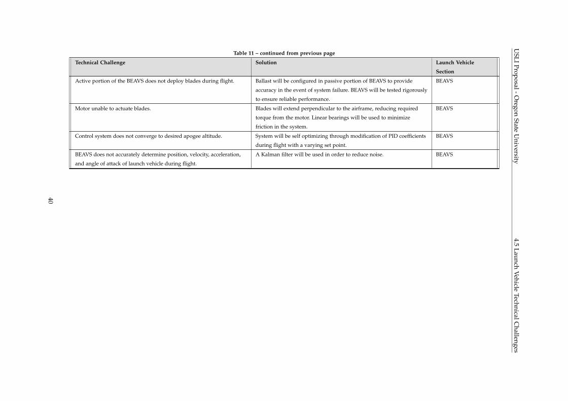
USLI
Proposal-Oregon
StateU
niversity4.5
LaunchVehicle
TechnicalChallenges
Table 11 – continued from previous page
Technical Challenge Solution Launch Vehicle
Section
Active portion of the BEAVS does not deploy blades during flight. Ballast will be configured in passive portion of BEAVS to provide
accuracy in the event of system failure. BEAVS will be tested rigorously
to ensure reliable performance.
BEAVS
Motor unable to actuate blades. Blades will extend perpendicular to the airframe, reducing required
torque from the motor. Linear bearings will be used to minimize
friction in the system.
BEAVS
Control system does not converge to desired apogee altitude. System will be self optimizing through modification of PID coefficients
during flight with a varying set point.
BEAVS
BEAVS does not accurately determine position, velocity, acceleration,
and angle of attack of launch vehicle during flight.
A Kalman filter will be used in order to reduce noise. BEAVS
40
USLI Proposal - Oregon State University 4.6 Payload - Deployable Rover
4.6 Payload - Deployable Rover
4.6.1 Payload Overview
The team will pursue the USLI deployable rover payload challenge. The rover’s purpose is to travel a
distance of at least ten feet from the landing site, collect a soil sample, and securely store it. An extra soil
analysis component may be included in the design; the team is considering options based on feasibility and
scientific value added to the mission. The requirements for this payload option, and the team’s plans to
meet them, are summarized in Table 12.
41
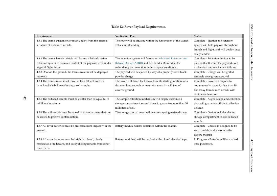
USLI
Proposal-Oregon
StateU
niversity4.6.1
PayloadO
verviewTable 12: Rover Payload Requirements.
Requirement Verification Plan Status
4.3.1 The team’s custom rover must deploy from the internal
structure of its launch vehicle.
The rover will be situated within the fore section of the launch
vehicle until landing.
Complete - Ejection and retention
system will hold payload throughout
launch and flight, and will deploy once
safely landed.
4.3.2 The team’s launch vehicle will feature a fail-safe active
retention system to maintain control of the payload, even under
atypical flight forces.
The retention system will feature an Advanced Retention and
Release Device (ARRD) and two Tender Descenders for
redundancy and retention under atypical conditions.
Complete - Retention devices to be
used will still retain the payload even
in electrical and mechanical failures.
4.3.3 Once on the ground, the team’s rover must be deployed
remotely.
The payload will be ejected by way of a properly sized black
powder charge.
Complete - Charge will be ignited
remotely once given approval.
4.3.4 The team’s rover must travel at least 10 feet from its
launch vehicle before collecting a soil sample.
The rover will drive itself away from its starting location for a
duration long enough to guarantee more than 10 feet of
covered ground.
Complete - Rover is designed to
autonomously travel further than 10
feet away from launch vehicle with
avoidance detection.
4.3.5 The collected sample must be greater than or equal to 10
milliliters in volume.
The sample collection mechanism will empty itself into a
storage compartment several times to guarantee more than 10
milliliters of soil.
Complete - Auger design and collection
plan will guaranty sufficient collection
volume.
4.3.6 The soil sample must be stored in a compartment that can
be closed to prevent contamination.
The storage compartment will feature a spring-assisted cover. Complete - Design includes closing
storage compartment to seal collected
sample.
4.3.7 All rover batteries must be protected from impact with the
ground.
Battery module will be contained within the chassis. Complete - Chassis is designed to be
very durable, and surrounds the
battery module
4.3.8 All rover batteries must be brightly colored, clearly
marked as a fire hazard, and easily distinguishable from other
rover parts.
Battery module(s) will be marked with colored electrical tape. In Progress - Batteries will be marked
once purchased.
42
USLI Proposal - Oregon State University 4.6.2 Payload Ejection and Retention System
The team intends to build a dual wheel rover with a roughly cylindrical form factor. Its chassis will be a truss
with carbon fiber rods and aluminum couplers. Mounted to its chassis, at its midpoint, will be an auger-
type tool for sample collection. The rover will be retained as described below in the Ejection and Retention
System (EARS), which is situated lengthwise in the payload bay in the 5.2" inner diameter airframe.
The payload’s sequence of events is as follows:
1) The rover and EARS are packed within the payload bay in the fore section of the launch vehicle at
launch.
2) During flight, the payload bay will separate from the aft section of the launch vehicle leaving the end
of the payload bay open, and with the help of the fore drogue and main chute, come to rest on the
ground.
3) Shortly after landing, under supervision of the Remote Deployment Officer, the team will remotely
ignite the retention devices holding the rover in the payload bay, and then ignite a black powder
charge that will eject the rover from the fore section of the launch vehicle.
4) The dual wheel design combined with a stabilizing tail will allow the rover to simply and autonomously
orient itself into the position necessary to carry out the mission–that is, with its auger pointed toward
the ground.
5) The rover will travel more than 10 feet from its starting position, using object avoidance in order to
navigate away from airframe components and other ground obstacles.
6) The rover will extend its auger, drill into the soil, and collect a sample, repeating several times in several
locations to ensure the sample exceeds the 10 milliliter requirement. The mission is complete.
4.6.2 Payload Ejection and Retention System
The payload EARS will be fully removable from the airframe to ensure all energetic charges are not loaded
or wired until assembly at the launch site. The system is all mounted and spaced on a threaded rod prior
to insertion in the airframe. The components mounted along the rod are listed below, and can be seen
numbered in Figure 13:
1) Removable High-density polyethylene (HDPE) tip
2) Threaded rod
3) Fore spacer bulkhead
4) Electronics bay for ejection and retention charges
5) Aft Spacer Bulkhead
6) Retention devices and ejection charges
7) Payload spacer on end of threaded rod
8) Wrapped payload assembly.
43
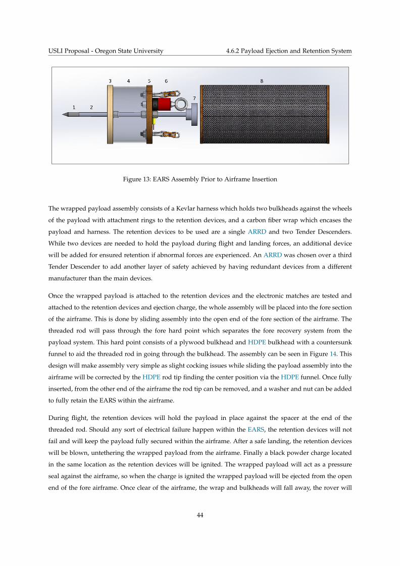
USLI Proposal - Oregon State University 4.6.2 Payload Ejection and Retention System
Figure 13: EARS Assembly Prior to Airframe Insertion
The wrapped payload assembly consists of a Kevlar harness which holds two bulkheads against the wheels
of the payload with attachment rings to the retention devices, and a carbon fiber wrap which encases the
payload and harness. The retention devices to be used are a single ARRD and two Tender Descenders.
While two devices are needed to hold the payload during flight and landing forces, an additional device
will be added for ensured retention if abnormal forces are experienced. An ARRD was chosen over a third
Tender Descender to add another layer of safety achieved by having redundant devices from a different
manufacturer than the main devices.
Once the wrapped payload is attached to the retention devices and the electronic matches are tested and
attached to the retention devices and ejection charge, the whole assembly will be placed into the fore section
of the airframe. This is done by sliding assembly into the open end of the fore section of the airframe. The
threaded rod will pass through the fore hard point which separates the fore recovery system from the
payload system. This hard point consists of a plywood bulkhead and HDPE bulkhead with a countersunk
funnel to aid the threaded rod in going through the bulkhead. The assembly can be seen in Figure 14. This
design will make assembly very simple as slight cocking issues while sliding the payload assembly into the
airframe will be corrected by the HDPE rod tip finding the center position via the HDPE funnel. Once fully
inserted, from the other end of the airframe the rod tip can be removed, and a washer and nut can be added
to fully retain the EARS within the airframe.
During flight, the retention devices will hold the payload in place against the spacer at the end of the
threaded rod. Should any sort of electrical failure happen within the EARS, the retention devices will not
fail and will keep the payload fully secured within the airframe. After a safe landing, the retention devices
will be blown, untethering the wrapped payload from the airframe. Finally a black powder charge located
in the same location as the retention devices will be ignited. The wrapped payload will act as a pressure
seal against the airframe, so when the charge is ignited the wrapped payload will be ejected from the open
end of the fore airframe. Once clear of the airframe, the wrap and bulkheads will fall away, the rover will
44

USLI Proposal - Oregon State University 4.6.3 Payload Details
Figure 14: EARS Assembly into Airframe
land in any oriention, self-right, and be ready to drive away to collect and analyze a soil sample. While the
EARS is simple, there were some technical challenges that needed to be addressed as can be seen in Table
13.
Table 13: EARS Technical Challenges and Solutions
Technical Challenge Solution
Difficult EARS assembly into airframe HDPE funnel bulkhead will aid threaded rod through fore hard point
by centering rod regardless of system cocking.
Pressure seal on between payload and
airframe
Foam tires on rover wheels will allow rover to be compressed in carbon
fiber wrap and inserted into the airframe. The foam tires will then
expand until the wrap is sealed to the ID of the airframe.
4.6.3 Payload Details
The rover’s drivetrain will employ two 4.8" diameter circular wheels cut from 0.75" HDPE, which is known
for its impact resistance and strength relative to weight. This material also has negligible thermal expansion
up to 130 ◦C, which is important for safe and predictable ejection from the airframe. The interior disk of the
wheels will be solid to mitigate the risk of debris entering the drivetrain mechanism.
The wheels must be able to grip the ground surface once deployed; failure to do so may leave the rover
stuck on an obstacle or slick surface with its wheels spinning. To avoid this, the team will apply a length
of memory foam to the tread of each wheel which matches its width and circumference. This will give a
better friction coefficient. A secondary benefit of this foam "tire" is that it can be compressed while within
the wrapped payload. The increase in radius that occurs when the foam decompresses gives the rover’s
45
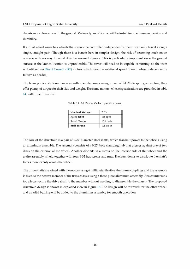
USLI Proposal - Oregon State University 4.6.3 Payload Details
chassis more clearance with the ground. Various types of foams will be tested for maximum expansion and
durability.
If a dual wheel rover has wheels that cannot be controlled independently, then it can only travel along a
single, straight path. Though there is a benefit here in simpler design, the risk of becoming stuck on an
obstacle with no way to avoid it is too severe to ignore. This is particularly important since the ground
surface at the launch location is unpredictable. The rover will need to be capable of turning, so the team
will utilize two Direct Current (DC) motors which vary the rotational speed of each wheel independently
to turn as needed.
The team previously found success with a similar rover using a pair of GHM-04 spur gear motors; they
offer plenty of torque for their size and weight. The same motors, whose specifications are provided in table
14, will drive this rover.
Table 14: GHM-04 Motor Specifications.
Nominal Voltage 7.2 V
Rated RPM 146 rpm
Rated Torque 13.9 oz-in
Stall Torque 125 oz-in
The core of the drivetrain is a pair of 0.25" diameter steel shafts, which transmit power to the wheels using
an aluminum assembly. The assembly consists of a 0.25" bore clamping hub that presses against one of two
discs on the exterior of the wheel. Another disc sits in a recess on the interior side of the wheel and the
entire assembly is held together with four 6-32 hex screws and nuts. The intention is to distribute the shaft’s
forces more evenly across the wheel.
The drive shafts are joined with the motors using 6 millimeter flexible aluminum couplings and the assembly
is fixed to the nearest member of the truss chassis using a three-piece aluminum assembly. Two countersunk
top pieces secure the drive shaft to the member without needing to disassemble the chassis. The proposed
drivetrain design is shown in exploded view in Figure 15. The design will be mirrored for the other wheel,
and a radial bearing will be added to the aluminum assembly for smooth operation.
46
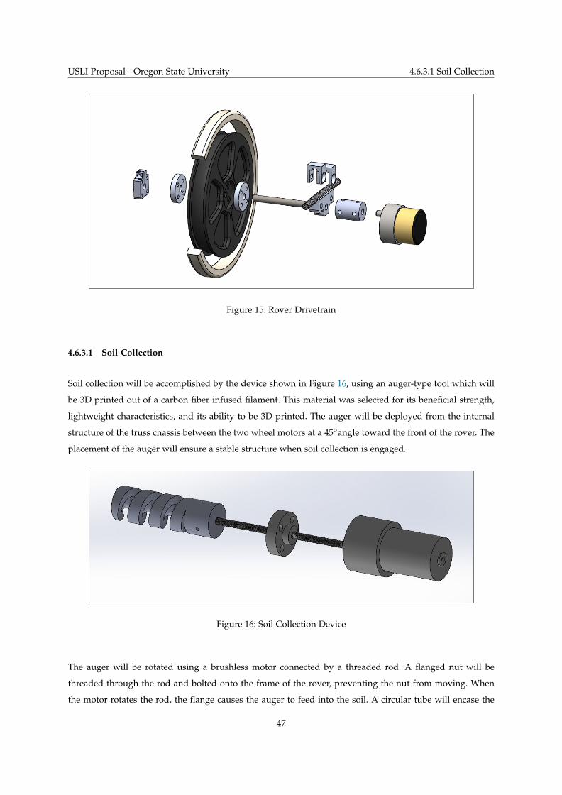
USLI Proposal - Oregon State University 4.6.3.1 Soil Collection
Figure 15: Rover Drivetrain
4.6.3.1 Soil Collection
Soil collection will be accomplished by the device shown in Figure 16, using an auger-type tool which will
be 3D printed out of a carbon fiber infused filament. This material was selected for its beneficial strength,
lightweight characteristics, and its ability to be 3D printed. The auger will be deployed from the internal
structure of the truss chassis between the two wheel motors at a 45◦angle toward the front of the rover. The
placement of the auger will ensure a stable structure when soil collection is engaged.
Figure 16: Soil Collection Device
The auger will be rotated using a brushless motor connected by a threaded rod. A flanged nut will be
threaded through the rod and bolted onto the frame of the rover, preventing the nut from moving. When
the motor rotates the rod, the flange causes the auger to feed into the soil. A circular tube will encase the
47
USLI Proposal - Oregon State University 4.6.3.2 Electrical Design
auger, which will be used to retain the soil during transportation from the ground to the soil container.
Once the soil reaches the top of the auger, it will fall downward by gravity into the soil storage container.
The soil storage container will use spring-assisted doors to seal a sample of at least 10 milliliter. When the
soil falls onto the container doors, the weight will cause the spring-assisted doors to open into the container,
allowing soil to fall. When there is no longer soil contacting the doors, they will close to seal the container.
Multiple samples may need to be collected to fulfill the 10 milliliter sample requirement.
One motor will be needed for the soil collection operation. A high-torque/low-speed motor will be used
for the auger rotation/feed. A Planetary Gear Motor PGHM-03 will be used. The specification of this motor
are listed in Table 15 below.
Table 15: PGHM-01 Motor Specifications.
Nominal Voltage 12.0 V
Rated RPM 14 rpm
Rated Torque 208.31 oz-in
Stall Torque 499.95 oz-in
4.6.3.2 Electrical Design
The rover will use MB7360 HRXL-MaxSonar-WR sensors placed in the front to determine distance traveled
as well as identify upcoming terrain hazards where an open-loop control system will reroute the rover to
avoid the hazard. A Raspberry Pi will control the function of the rover. LiPo batteries will be used due to
their small size and high current delivery capabilities.
48
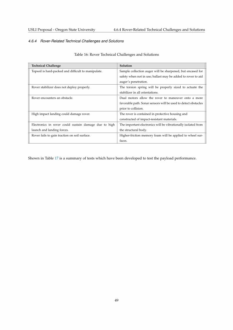
USLI Proposal - Oregon State University 4.6.4 Rover-Related Technical Challenges and Solutions
4.6.4 Rover-Related Technical Challenges and Solutions
Table 16: Rover Technical Challenges and Solutions
Technical Challenge Solution
Topsoil is hard-packed and difficult to manipulate. Sample collection auger will be sharpened, but encased for
safety when not in use; ballast may be added to rover to aid
auger’s penetration.
Rover stabilizer does not deploy properly. The torsion spring will be properly sized to actuate the
stabilizer in all orientations.
Rover encounters an obstacle. Dual motors allow the rover to maneuver onto a more
favorable path. Sonar sensors will be used to detect obstacles
prior to collision.
High impact landing could damage rover. The rover is contained in protective housing and
constructed of impact-resistant materials.
Electronics in rover could sustain damage due to high
launch and landing forces.
The important electronics will be vibrationally isolated from
the structural body.
Rover fails to gain traction on soil surface. Higher-friction memory foam will be applied to wheel sur-
faces.
Shown in Table 17 is a summary of tests which have been developed to test the payload performance.
49
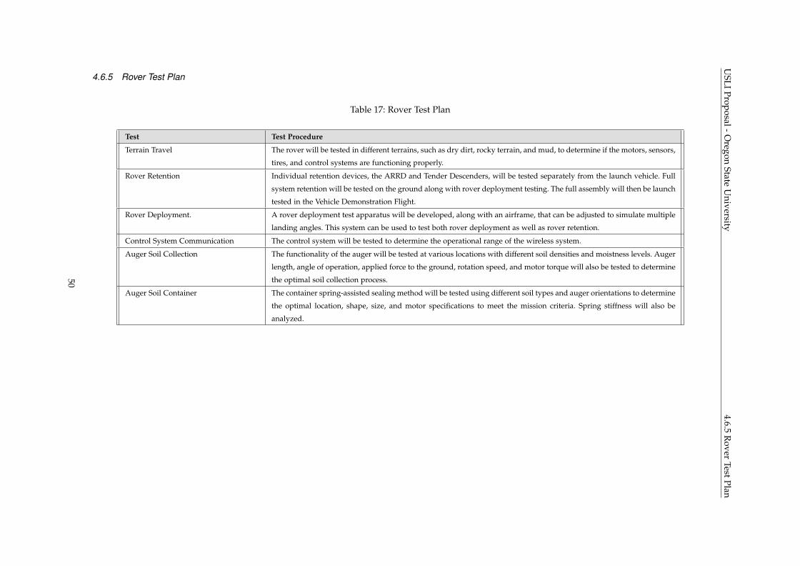
USLI
Proposal-Oregon
StateU
niversity4.6.5
Rover
TestPlan4.6.5 Rover Test Plan
Table 17: Rover Test Plan
Test Test Procedure
Terrain Travel The rover will be tested in different terrains, such as dry dirt, rocky terrain, and mud, to determine if the motors, sensors,
tires, and control systems are functioning properly.
Rover Retention Individual retention devices, the ARRD and Tender Descenders, will be tested separately from the launch vehicle. Full
system retention will be tested on the ground along with rover deployment testing. The full assembly will then be launch
tested in the Vehicle Demonstration Flight.
Rover Deployment. A rover deployment test apparatus will be developed, along with an airframe, that can be adjusted to simulate multiple
landing angles. This system can be used to test both rover deployment as well as rover retention.
Control System Communication The control system will be tested to determine the operational range of the wireless system.
Auger Soil Collection The functionality of the auger will be tested at various locations with different soil densities and moistness levels. Auger
length, angle of operation, applied force to the ground, rotation speed, and motor torque will also be tested to determine
the optimal soil collection process.
Auger Soil Container The container spring-assisted sealing method will be tested using different soil types and auger orientations to determine
the optimal location, shape, size, and motor specifications to meet the mission criteria. Spring stiffness will also be
analyzed.
50
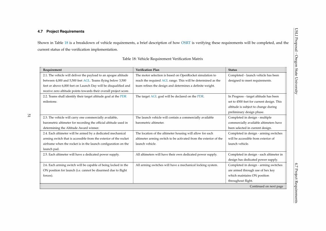
USLI
Proposal-Oregon
StateU
niversity4.7
ProjectRequirem
ents4.7 Project Requirements
Shown in Table 18 is a breakdown of vehicle requirements, a brief description of how OSRT is verifying these requirements will be completed, and the
current status of the verification implementation.
Table 18: Vehicle Requirement Verification Matrix
Requirement Verification Plan Status
2.1. The vehicle will deliver the payload to an apogee altitude
between 4,000 and 5,500 feet AGL. Teams flying below 3,500
feet or above 6,000 feet on Launch Day will be disqualified and
receive zero altitude points towards their overall project score.
The motor selection is based on OpenRocket simulation to
reach the required AGL range. This will be determined as the
team refines the design and determines a definite weight.
Completed - launch vehicle has been
designed to meet requirements.
2.2. Teams shall identify their target altitude goal at the PDR
milestone.
The target AGL goal will be declared on the PDR. In Progress - target altitude has been
set to 4500 feet for current design. This
altitude is subject to change during
preliminary design phase.
2.3. The vehicle will carry one commercially available,
barometric altimeter for recording the official altitude used in
determining the Altitude Award winner.
The launch vehicle will contain a commercially available
barometric altimeter.
Completed in design - multiple
commercially available altimeters have
been selected in current design.
2.4. Each altimeter will be armed by a dedicated mechanical
arming switch that is accessible from the exterior of the rocket
airframe when the rocket is in the launch configuration on the
launch pad.
The location of the altimeter housing will allow for each
altimeter arming switch to be activated from the exterior of the
launch vehicle.
Completed in design - arming switches
will be accessible from exterior of
launch vehicle.
2.5. Each altimeter will have a dedicated power supply. All altimeters will have their own dedicated power supply. Completed in design - each altimeter in
design has dedicated power supply.
2.6. Each arming switch will be capable of being locked in the
ON position for launch (i.e. cannot be disarmed due to flight
forces).
All arming switches will have a mechanical locking system. Completed in design - arming switches
are armed through use of hex key
which maintains ON position
throughout flight.
Continued on next page
51
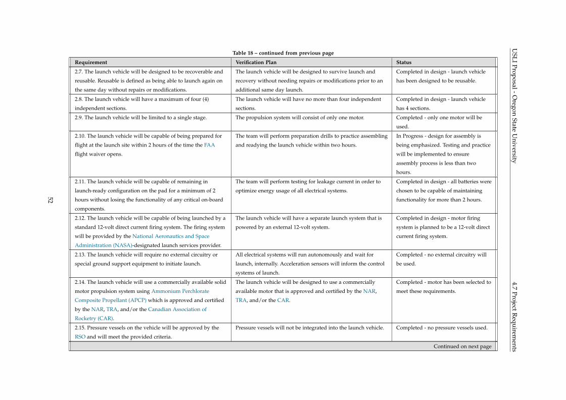
USLI
Proposal-Oregon
StateU
niversity4.7
ProjectRequirem
entsTable 18 – continued from previous page
Requirement Verification Plan Status
2.7. The launch vehicle will be designed to be recoverable and
reusable. Reusable is defined as being able to launch again on
the same day without repairs or modifications.
The launch vehicle will be designed to survive launch and
recovery without needing repairs or modifications prior to an
additional same day launch.
Completed in design - launch vehicle
has been designed to be reusable.
2.8. The launch vehicle will have a maximum of four (4)
independent sections.
The launch vehicle will have no more than four independent
sections.
Completed in design - launch vehicle
has 4 sections.
2.9. The launch vehicle will be limited to a single stage. The propulsion system will consist of only one motor. Completed - only one motor will be
used.
2.10. The launch vehicle will be capable of being prepared for
flight at the launch site within 2 hours of the time the FAA
flight waiver opens.
The team will perform preparation drills to practice assembling
and readying the launch vehicle within two hours.
In Progress - design for assembly is
being emphasized. Testing and practice
will be implemented to ensure
assembly process is less than two
hours.
2.11. The launch vehicle will be capable of remaining in
launch-ready configuration on the pad for a minimum of 2
hours without losing the functionality of any critical on-board
components.
The team will perform testing for leakage current in order to
optimize energy usage of all electrical systems.
Completed in design - all batteries were
chosen to be capable of maintaining
functionality for more than 2 hours.
2.12. The launch vehicle will be capable of being launched by a
standard 12-volt direct current firing system. The firing system
will be provided by the National Aeronautics and Space
Administration (NASA)-designated launch services provider.
The launch vehicle will have a separate launch system that is
powered by an external 12-volt system.
Completed in design - motor firing
system is planned to be a 12-volt direct
current firing system.
2.13. The launch vehicle will require no external circuitry or
special ground support equipment to initiate launch.
All electrical systems will run autonomously and wait for
launch, internally. Acceleration sensors will inform the control
systems of launch.
Completed - no external circuitry will
be used.
2.14. The launch vehicle will use a commercially available solid
motor propulsion system using Ammonium Perchlorate
Composite Propellant (APCP) which is approved and certified
by the NAR, TRA, and/or the Canadian Association of
Rocketry (CAR).
The launch vehicle will be designed to use a commercially
available motor that is approved and certified by the NAR,
TRA, and/or the CAR.
Completed - motor has been selected to
meet these requirements.
2.15. Pressure vessels on the vehicle will be approved by the
RSO and will meet the provided criteria.
Pressure vessels will not be integrated into the launch vehicle. Completed - no pressure vessels used.
Continued on next page
52
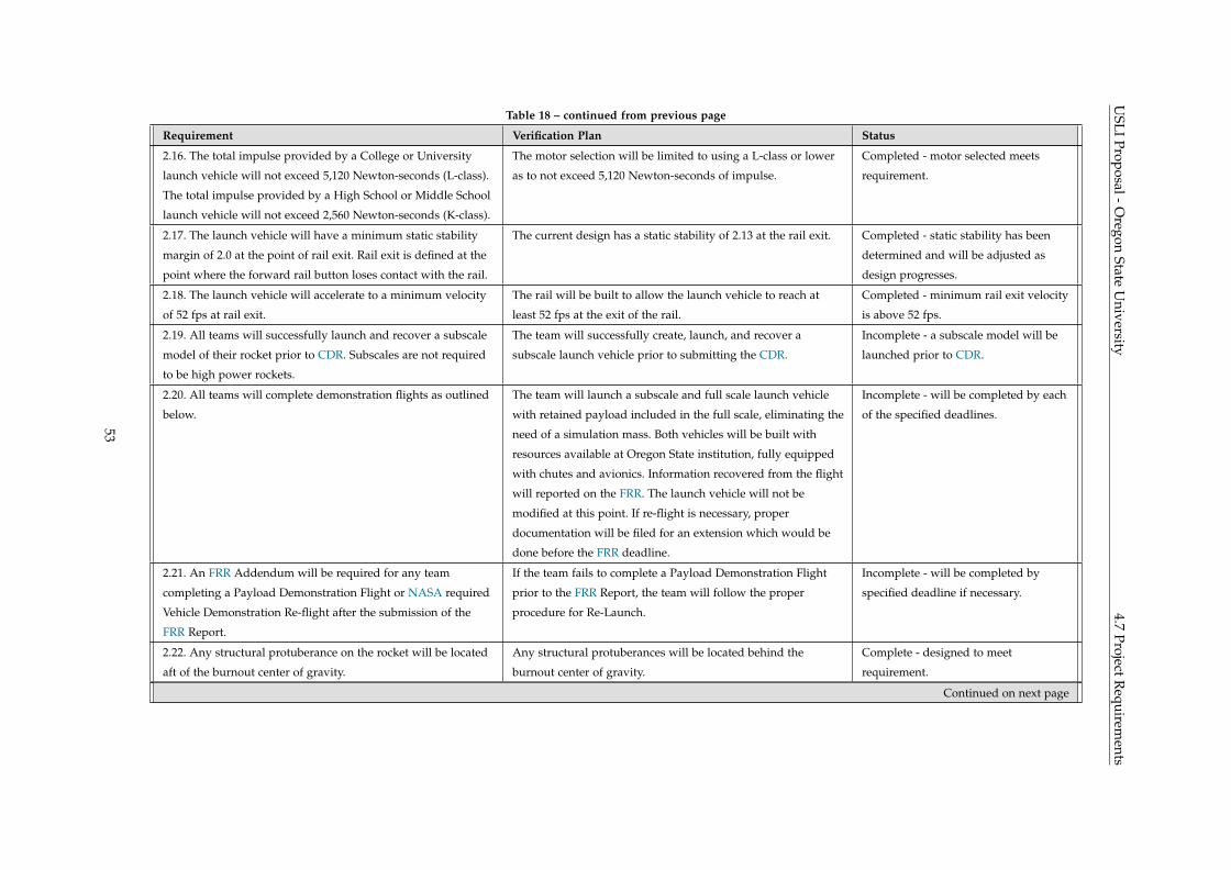
USLI
Proposal-Oregon
StateU
niversity4.7
ProjectRequirem
entsTable 18 – continued from previous page
Requirement Verification Plan Status
2.16. The total impulse provided by a College or University
launch vehicle will not exceed 5,120 Newton-seconds (L-class).
The total impulse provided by a High School or Middle School
launch vehicle will not exceed 2,560 Newton-seconds (K-class).
The motor selection will be limited to using a L-class or lower
as to not exceed 5,120 Newton-seconds of impulse.
Completed - motor selected meets
requirement.
2.17. The launch vehicle will have a minimum static stability
margin of 2.0 at the point of rail exit. Rail exit is defined at the
point where the forward rail button loses contact with the rail.
The current design has a static stability of 2.13 at the rail exit. Completed - static stability has been
determined and will be adjusted as
design progresses.
2.18. The launch vehicle will accelerate to a minimum velocity
of 52 fps at rail exit.
The rail will be built to allow the launch vehicle to reach at
least 52 fps at the exit of the rail.
Completed - minimum rail exit velocity
is above 52 fps.
2.19. All teams will successfully launch and recover a subscale
model of their rocket prior to CDR. Subscales are not required
to be high power rockets.
The team will successfully create, launch, and recover a
subscale launch vehicle prior to submitting the CDR.
Incomplete - a subscale model will be
launched prior to CDR.
2.20. All teams will complete demonstration flights as outlined
below.
The team will launch a subscale and full scale launch vehicle
with retained payload included in the full scale, eliminating the
need of a simulation mass. Both vehicles will be built with
resources available at Oregon State institution, fully equipped
with chutes and avionics. Information recovered from the flight
will reported on the FRR. The launch vehicle will not be
modified at this point. If re-flight is necessary, proper
documentation will be filed for an extension which would be
done before the FRR deadline.
Incomplete - will be completed by each
of the specified deadlines.
2.21. An FRR Addendum will be required for any team
completing a Payload Demonstration Flight or NASA required
Vehicle Demonstration Re-flight after the submission of the
FRR Report.
If the team fails to complete a Payload Demonstration Flight
prior to the FRR Report, the team will follow the proper
procedure for Re-Launch.
Incomplete - will be completed by
specified deadline if necessary.
2.22. Any structural protuberance on the rocket will be located
aft of the burnout center of gravity.
Any structural protuberances will be located behind the
burnout center of gravity.
Complete - designed to meet
requirement.
Continued on next page
53
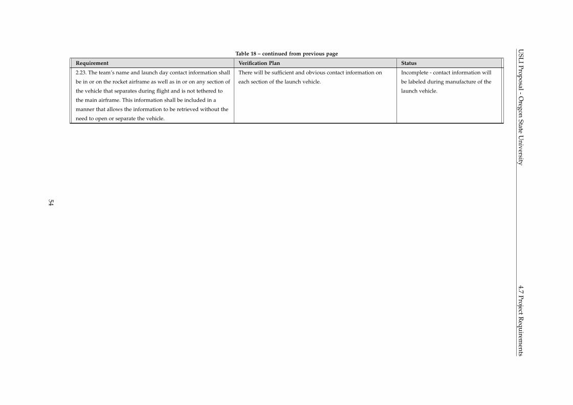
USLI
Proposal-Oregon
StateU
niversity4.7
ProjectRequirem
entsTable 18 – continued from previous page
Requirement Verification Plan Status
2.23. The team’s name and launch day contact information shall
be in or on the rocket airframe as well as in or on any section of
the vehicle that separates during flight and is not tethered to
the main airframe. This information shall be included in a
manner that allows the information to be retrieved without the
need to open or separate the vehicle.
There will be sufficient and obvious contact information on
each section of the launch vehicle.
Incomplete - contact information will
be labeled during manufacture of the
launch vehicle.
54
USLI Proposal - Oregon State University 4.7.1 Vehicle Prohibitions
4.7.1 Vehicle Prohibitions
Shown in Table 19 is a breakdown prohibited aspects of the vehicle, a brief description of how OSRT is
verifying these requirements will be completed, and the current status of the verification implementation.
55
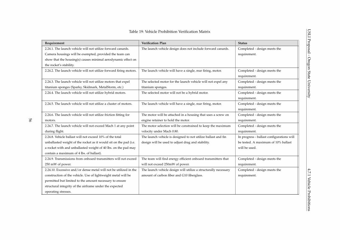
USLI
Proposal-Oregon
StateU
niversity4.7.1
VehicleProhibitions
Table 19: Vehicle Prohibition Verification Matrix
Requirement Verification Plan Status
2.24.1. The launch vehicle will not utilize forward canards.
Camera housings will be exempted, provided the team can
show that the housing(s) causes minimal aerodynamic effect on
the rocket’s stability.
The launch vehicle design does not include forward canards. Completed - design meets the
requirement.
2.24.2. The launch vehicle will not utilize forward firing motors. The launch vehicle will have a single, rear firing, motor. Completed - design meets the
requirement.
2.24.3. The launch vehicle will not utilize motors that expel
titanium sponges (Sparky, Skidmark, MetalStorm, etc.)
The selected motor for the launch vehicle will not expel any
titanium sponges.
Completed - design meets the
requirement.
2.24.4. The launch vehicle will not utilize hybrid motors. The selected motor will not be a hybrid motor. Completed - design meets the
requirement.
2.24.5. The launch vehicle will not utilize a cluster of motors. The launch vehicle will have a single, rear firing, motor. Completed - design meets the
requirement.
2.24.6. The launch vehicle will not utilize friction fitting for
motors.
The motor will be attached in a housing that uses a screw on
engine retainer to hold the motor.
Completed - design meets the
requirement.
2.24.7. The launch vehicle will not exceed Mach 1 at any point
during flight.
The motor selection will be constrained to keep the maximum
velocity under Mach 0.80.
Completed - design meets the
requirement.
2.24.8. Vehicle ballast will not exceed 10% of the total
unballasted weight of the rocket as it would sit on the pad (i.e.
a rocket with and unballasted weight of 40 lbs. on the pad may
contain a maximum of 4 lbs. of ballast).
The launch vehicle is designed to not utilize ballast and fin
design will be used to adjust drag and stability.
In progress - ballast configurations will
be tested. A maximum of 10% ballast
will be used.
2.24.9. Transmissions from onboard transmitters will not exceed
250 mW of power.
The team will find energy efficient onboard transmitters that
will not exceed 250mW of power.
Completed - design meets the
requirement.
2.24.10. Excessive and/or dense metal will not be utilized in the
construction of the vehicle. Use of lightweight metal will be
permitted but limited to the amount necessary to ensure
structural integrity of the airframe under the expected
operating stresses.
The launch vehicle design will utilize a structurally necessary
amount of carbon fiber and G10 fiberglass.
Completed - design meets the
requirement.
56
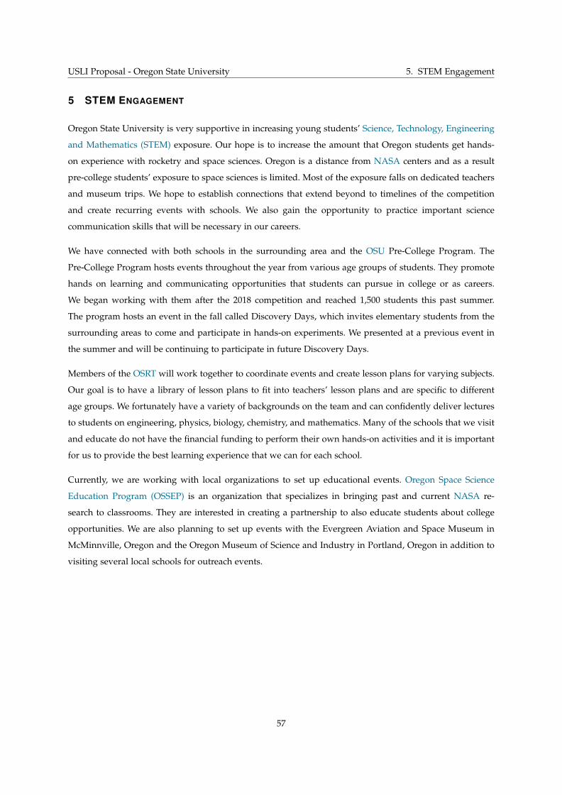
USLI Proposal - Oregon State University 5. STEM Engagement
5 STEM ENGAGEMENT
Oregon State University is very supportive in increasing young students’ Science, Technology, Engineering
and Mathematics (STEM) exposure. Our hope is to increase the amount that Oregon students get hands-
on experience with rocketry and space sciences. Oregon is a distance from NASA centers and as a result
pre-college students’ exposure to space sciences is limited. Most of the exposure falls on dedicated teachers
and museum trips. We hope to establish connections that extend beyond to timelines of the competition
and create recurring events with schools. We also gain the opportunity to practice important science
communication skills that will be necessary in our careers.
We have connected with both schools in the surrounding area and the OSU Pre-College Program. The
Pre-College Program hosts events throughout the year from various age groups of students. They promote
hands on learning and communicating opportunities that students can pursue in college or as careers.
We began working with them after the 2018 competition and reached 1,500 students this past summer.
The program hosts an event in the fall called Discovery Days, which invites elementary students from the
surrounding areas to come and participate in hands-on experiments. We presented at a previous event in
the summer and will be continuing to participate in future Discovery Days.
Members of the OSRT will work together to coordinate events and create lesson plans for varying subjects.
Our goal is to have a library of lesson plans to fit into teachers’ lesson plans and are specific to different
age groups. We fortunately have a variety of backgrounds on the team and can confidently deliver lectures
to students on engineering, physics, biology, chemistry, and mathematics. Many of the schools that we visit
and educate do not have the financial funding to perform their own hands-on activities and it is important
for us to provide the best learning experience that we can for each school.
Currently, we are working with local organizations to set up educational events. Oregon Space Science
Education Program (OSSEP) is an organization that specializes in bringing past and current NASA re-
search to classrooms. They are interested in creating a partnership to also educate students about college
opportunities. We are also planning to set up events with the Evergreen Aviation and Space Museum in
McMinnville, Oregon and the Oregon Museum of Science and Industry in Portland, Oregon in addition to
visiting several local schools for outreach events.
57

USLI Proposal - Oregon State University 6. Project Plan
6 PROJECT PLAN
6.1 Schedule
A comprehensive schedule has been developed for the 2018-2019 year. This schedule is displayed in Figures
17-19.
58
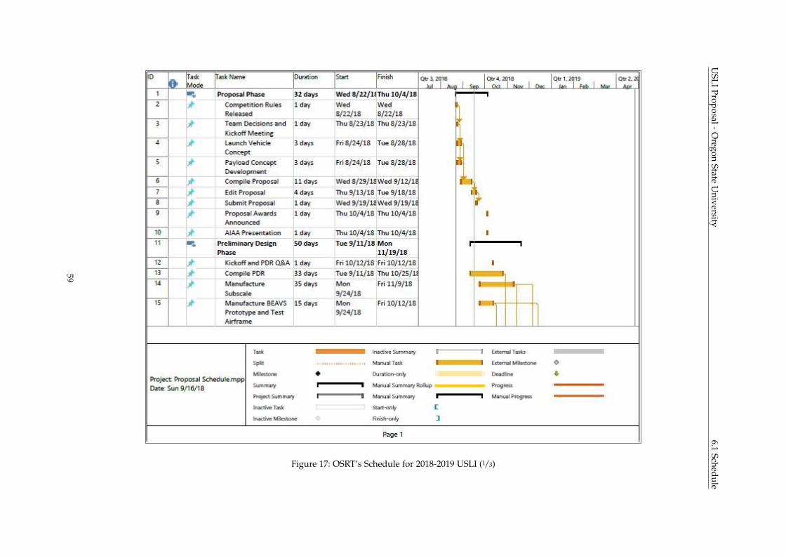
USLI
Proposal-Oregon
StateU
niversity6.1
Schedule
Figure 17: OSRT’s Schedule for 2018-2019 USLI (1/3)
59
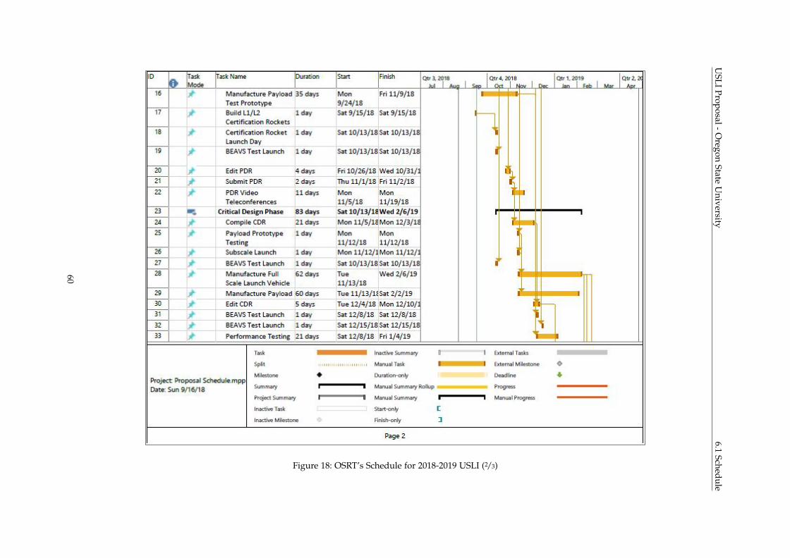
USLI
Proposal-Oregon
StateU
niversity6.1
Schedule
Figure 18: OSRT’s Schedule for 2018-2019 USLI (2/3)
60
USLI
Proposal-Oregon
StateU
niversity6.1
Schedule
Figure 19: OSRT’s Schedule for 2018-2019 USLI (3/3)
61
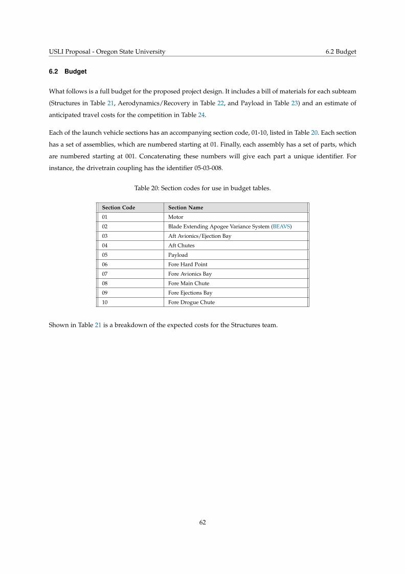
USLI Proposal - Oregon State University 6.2 Budget
6.2 Budget
What follows is a full budget for the proposed project design. It includes a bill of materials for each subteam
(Structures in Table 21, Aerodynamics/Recovery in Table 22, and Payload in Table 23) and an estimate of
anticipated travel costs for the competition in Table 24.
Each of the launch vehicle sections has an accompanying section code, 01-10, listed in Table 20. Each section
has a set of assemblies, which are numbered starting at 01. Finally, each assembly has a set of parts, which
are numbered starting at 001. Concatenating these numbers will give each part a unique identifier. For
instance, the drivetrain coupling has the identifier 05-03-008.
Table 20: Section codes for use in budget tables.
Section Code Section Name
01 Motor
02 Blade Extending Apogee Variance System (BEAVS)
03 Aft Avionics/Ejection Bay
04 Aft Chutes
05 Payload
06 Fore Hard Point
07 Fore Avionics Bay
08 Fore Main Chute
09 Fore Ejections Bay
10 Fore Drogue Chute
Shown in Table 21 is a breakdown of the expected costs for the Structures team.
62
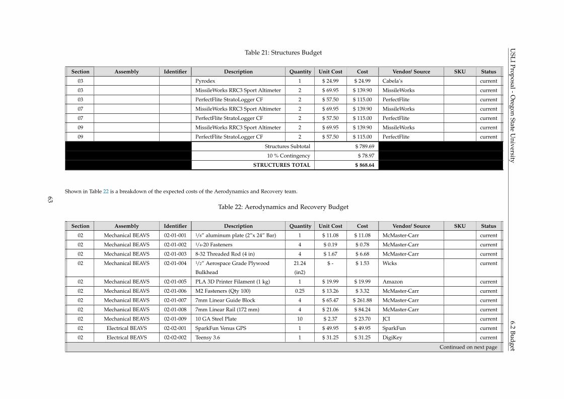
USLI
Proposal-Oregon
StateU
niversity6.2
BudgetTable 21: Structures Budget
Section Assembly Identifier Description Quantity Unit Cost Cost Vendor/ Source SKU Status
03 Pyrodex 1 $ 24.99 $ 24.99 Cabela’s current
03 MissileWorks RRC3 Sport Altimeter 2 $ 69.95 $ 139.90 MissileWorks current
03 PerfectFlite StratoLogger CF 2 $ 57.50 $ 115.00 PerfectFlite current
07 MissileWorks RRC3 Sport Altimeter 2 $ 69.95 $ 139.90 MissileWorks current
07 PerfectFlite StratoLogger CF 2 $ 57.50 $ 115.00 PerfectFlite current
09 MissileWorks RRC3 Sport Altimeter 2 $ 69.95 $ 139.90 MissileWorks current
09 PerfectFlite StratoLogger CF 2 $ 57.50 $ 115.00 PerfectFlite current
Structures Subtotal $ 789.69
10 % Contingency $ 78.97
STRUCTURES TOTAL $ 868.64
Shown in Table 22 is a breakdown of the expected costs of the Aerodynamics and Recovery team.
Table 22: Aerodynamics and Recovery Budget
Section Assembly Identifier Description Quantity Unit Cost Cost Vendor/ Source SKU Status
02 Mechanical BEAVS 02-01-001 1/8” aluminum plate (2”x 24” Bar) 1 $ 11.08 $ 11.08 McMaster-Carr current
02 Mechanical BEAVS 02-01-002 1/4-20 Fasteners 4 $ 0.19 $ 0.78 McMaster-Carr current
02 Mechanical BEAVS 02-01-003 8-32 Threaded Rod (4 in) 4 $ 1.67 $ 6.68 McMaster-Carr current
02 Mechanical BEAVS 02-01-004 1/2” Aerospace Grade Plywood
Bulkhead
21.24
(in2)
$ - $ 1.53 Wicks current
02 Mechanical BEAVS 02-01-005 PLA 3D Printer Filament (1 kg) 1 $ 19.99 $ 19.99 Amazon current
02 Mechanical BEAVS 02-01-006 M2 Fasteners (Qty 100) 0.25 $ 13.26 $ 3.32 McMaster-Carr current
02 Mechanical BEAVS 02-01-007 7mm Linear Guide Block 4 $ 65.47 $ 261.88 McMaster-Carr current
02 Mechanical BEAVS 02-01-008 7mm Linear Rail (172 mm) 4 $ 21.06 $ 84.24 McMaster-Carr current
02 Mechanical BEAVS 02-01-009 10 GA Steel Plate 10 $ 2.37 $ 23.70 JCI current
02 Electrical BEAVS 02-02-001 SparkFun Venus GPS 1 $ 49.95 $ 49.95 SparkFun current
02 Electrical BEAVS 02-02-002 Teensy 3.6 1 $ 31.25 $ 31.25 DigiKey current
Continued on next page
63

USLI
Proposal-Oregon
StateU
niversity6.2
BudgetTable 22 – continued from previous page
Section Assembly Identifier Description Quantity Unit Cost Cost Vendor/ Source SKU Status
02 Electrical BEAVS 02-02-003 MPL3115 Barometer 1 $ 4.87 $ 4.87 Mouser current
02 Electrical BEAVS 02-02-004 BNO055 9DOF IMU 1 $ 34.95 $ 34.95 Adafruit current
02 Electrical BEAVS 02-02-005 Turnigy 2200mah LiPo 1 $ 10.99 $ 10.99 HobbyKing current
02 Electrical BEAVS 02-02-006 OSRT Designed PCB 1 $ 92.90 $ 92.90 DFRobot current
02 Electrical BEAVS 02-02-007 Xbee Pro 900hp 1 $ 39.00 $ 39.00 DigiKey current
02 Electrical BEAVS 02-02-008 7 in RPSMA whip antenna 1 $ 4.29 $ 4.29 Amazon current
04 Main Parachute (Toroidal, 7’
diameter)
1 $ 276.00 $ 276.00 FruityChutes current
04 Drogue parachute (Cruciform, silk
body with nylon shroud lines, 28”
diameter, 500 in2)
1 $ 19.99 $ 19.99 AerospaceEducation current
04 Eye nuts (5/8-11 drop forged) 4 $ 8.60 $ 34.40 Grainger - Ken Forging current
04 Nuts $ - $ - current
04 Nylon shock cord (9/16”, 10 yd) 1 $ 29.00 $ 29.00 FruityChutes current
04 Quick links $ - $ - current
04 Swivel $ - $ - current
04 Nylon harness (1/2” harness, 5 ft) 1 $ 42.00 $ 42.00 FruityChutes current
04 Deployment bag (4 x 12”) 1 $ 45.00 $ 45.00 FruityChutes current
04 Nomex blanket (9”) 1 $ 13.00 $ 13.00 FruityChutes current
08 Main Parachute (Toroidal, 6’
diameter)
1 $ 210.00 $ 210.00 FruityChutes current
08 Eye nuts (5/8-11 drop forged) 2 $ 8.60 $ 17.20 Grainger - Ken Forging current
08 Nuts $ - $ - current
08 Nylon shock cord (9/16”, 10 yd) 1 $ 29.00 $ 29.00 FruityChutes current
08 Quick links $ - $ - current
08 Swivel $ - $ - current
08 Nylon harness (1/2” harness, 5 ft) 1 $ 42.00 $ 42.00 FruityChutes current
08 Deployment bag (4 x 15”) 1 $ 47.00 $ 47.00 FruityChutes current
Continued on next page
64
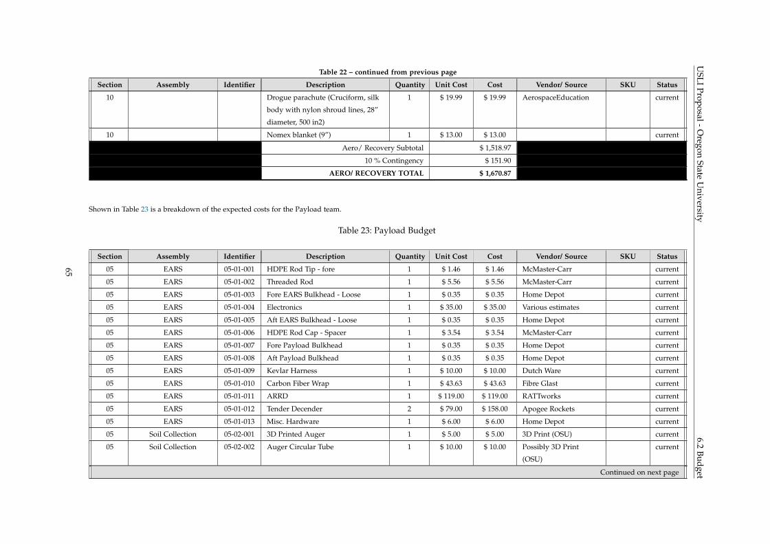
USLI
Proposal-Oregon
StateU
niversity6.2
BudgetTable 22 – continued from previous page
Section Assembly Identifier Description Quantity Unit Cost Cost Vendor/ Source SKU Status
10 Drogue parachute (Cruciform, silk
body with nylon shroud lines, 28”
diameter, 500 in2)
1 $ 19.99 $ 19.99 AerospaceEducation current
10 Nomex blanket (9”) 1 $ 13.00 $ 13.00 current
Aero/ Recovery Subtotal $ 1,518.97
10 % Contingency $ 151.90
AERO/ RECOVERY TOTAL $ 1,670.87
Shown in Table 23 is a breakdown of the expected costs for the Payload team.
Table 23: Payload Budget
Section Assembly Identifier Description Quantity Unit Cost Cost Vendor/ Source SKU Status
05 EARS 05-01-001 HDPE Rod Tip - fore 1 $ 1.46 $ 1.46 McMaster-Carr current
05 EARS 05-01-002 Threaded Rod 1 $ 5.56 $ 5.56 McMaster-Carr current
05 EARS 05-01-003 Fore EARS Bulkhead - Loose 1 $ 0.35 $ 0.35 Home Depot current
05 EARS 05-01-004 Electronics 1 $ 35.00 $ 35.00 Various estimates current
05 EARS 05-01-005 Aft EARS Bulkhead - Loose 1 $ 0.35 $ 0.35 Home Depot current
05 EARS 05-01-006 HDPE Rod Cap - Spacer 1 $ 3.54 $ 3.54 McMaster-Carr current
05 EARS 05-01-007 Fore Payload Bulkhead 1 $ 0.35 $ 0.35 Home Depot current
05 EARS 05-01-008 Aft Payload Bulkhead 1 $ 0.35 $ 0.35 Home Depot current
05 EARS 05-01-009 Kevlar Harness 1 $ 10.00 $ 10.00 Dutch Ware current
05 EARS 05-01-010 Carbon Fiber Wrap 1 $ 43.63 $ 43.63 Fibre Glast current
05 EARS 05-01-011 ARRD 1 $ 119.00 $ 119.00 RATTworks current
05 EARS 05-01-012 Tender Decender 2 $ 79.00 $ 158.00 Apogee Rockets current
05 EARS 05-01-013 Misc. Hardware 1 $ 6.00 $ 6.00 Home Depot current
05 Soil Collection 05-02-001 3D Printed Auger 1 $ 5.00 $ 5.00 3D Print (OSU) current
05 Soil Collection 05-02-002 Auger Circular Tube 1 $ 10.00 $ 10.00 Possibly 3D Print
(OSU)
current
Continued on next page
65
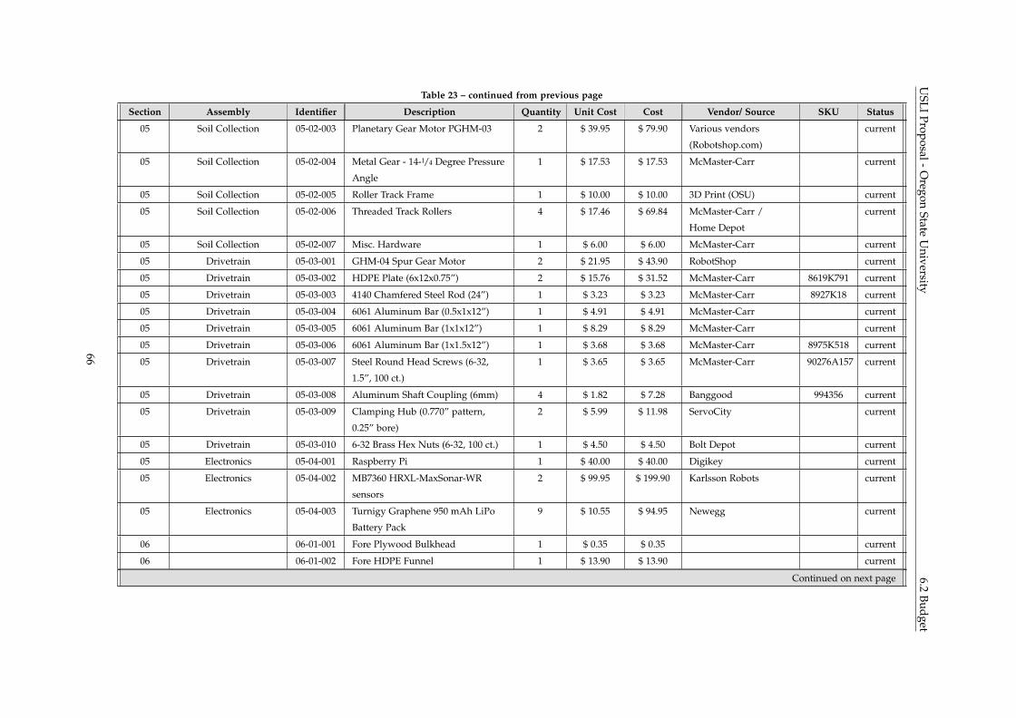
USLI
Proposal-Oregon
StateU
niversity6.2
BudgetTable 23 – continued from previous page
Section Assembly Identifier Description Quantity Unit Cost Cost Vendor/ Source SKU Status
05 Soil Collection 05-02-003 Planetary Gear Motor PGHM-03 2 $ 39.95 $ 79.90 Various vendors
(Robotshop.com)
current
05 Soil Collection 05-02-004 Metal Gear - 14-1/4 Degree Pressure
Angle
1 $ 17.53 $ 17.53 McMaster-Carr current
05 Soil Collection 05-02-005 Roller Track Frame 1 $ 10.00 $ 10.00 3D Print (OSU) current
05 Soil Collection 05-02-006 Threaded Track Rollers 4 $ 17.46 $ 69.84 McMaster-Carr /
Home Depot
current
05 Soil Collection 05-02-007 Misc. Hardware 1 $ 6.00 $ 6.00 McMaster-Carr current
05 Drivetrain 05-03-001 GHM-04 Spur Gear Motor 2 $ 21.95 $ 43.90 RobotShop current
05 Drivetrain 05-03-002 HDPE Plate (6x12x0.75”) 2 $ 15.76 $ 31.52 McMaster-Carr 8619K791 current
05 Drivetrain 05-03-003 4140 Chamfered Steel Rod (24”) 1 $ 3.23 $ 3.23 McMaster-Carr 8927K18 current
05 Drivetrain 05-03-004 6061 Aluminum Bar (0.5x1x12”) 1 $ 4.91 $ 4.91 McMaster-Carr current
05 Drivetrain 05-03-005 6061 Aluminum Bar (1x1x12”) 1 $ 8.29 $ 8.29 McMaster-Carr current
05 Drivetrain 05-03-006 6061 Aluminum Bar (1x1.5x12”) 1 $ 3.68 $ 3.68 McMaster-Carr 8975K518 current
05 Drivetrain 05-03-007 Steel Round Head Screws (6-32,
1.5”, 100 ct.)
1 $ 3.65 $ 3.65 McMaster-Carr 90276A157 current
05 Drivetrain 05-03-008 Aluminum Shaft Coupling (6mm) 4 $ 1.82 $ 7.28 Banggood 994356 current
05 Drivetrain 05-03-009 Clamping Hub (0.770” pattern,
0.25” bore)
2 $ 5.99 $ 11.98 ServoCity current
05 Drivetrain 05-03-010 6-32 Brass Hex Nuts (6-32, 100 ct.) 1 $ 4.50 $ 4.50 Bolt Depot current
05 Electronics 05-04-001 Raspberry Pi 1 $ 40.00 $ 40.00 Digikey current
05 Electronics 05-04-002 MB7360 HRXL-MaxSonar-WR
sensors
2 $ 99.95 $ 199.90 Karlsson Robots current
05 Electronics 05-04-003 Turnigy Graphene 950 mAh LiPo
Battery Pack
9 $ 10.55 $ 94.95 Newegg current
06 06-01-001 Fore Plywood Bulkhead 1 $ 0.35 $ 0.35 current
06 06-01-002 Fore HDPE Funnel 1 $ 13.90 $ 13.90 current
Continued on next page
66
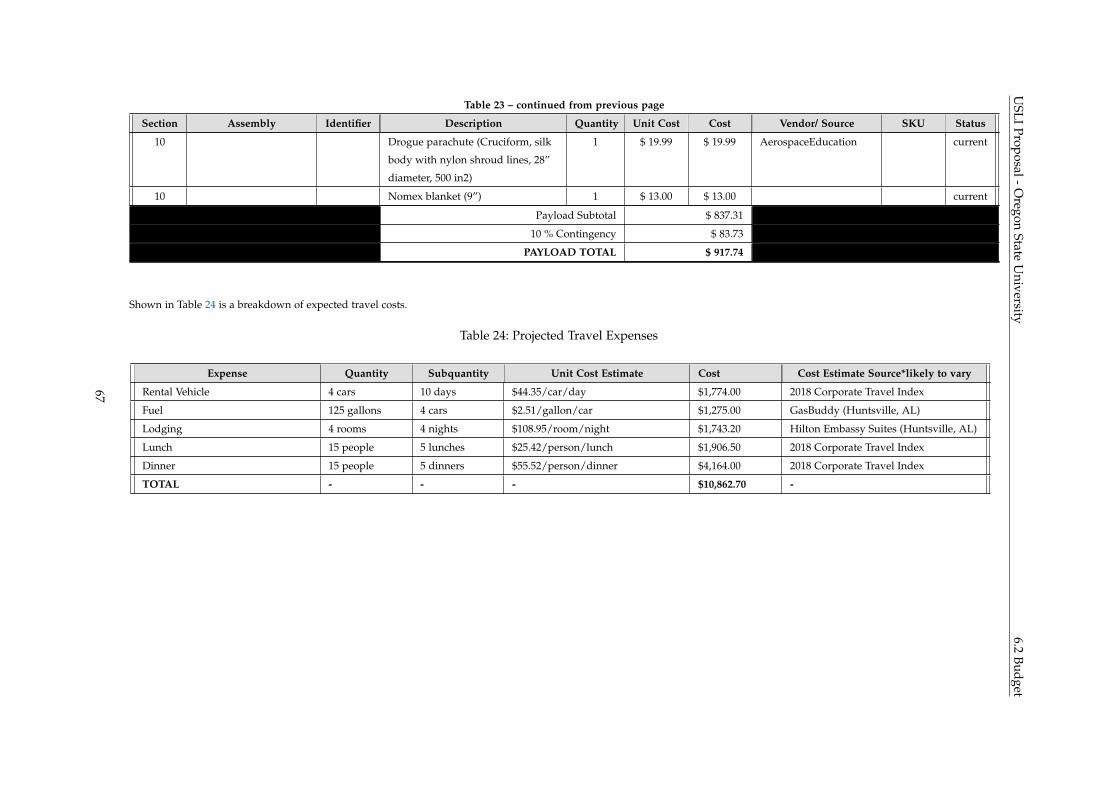
USLI
Proposal-Oregon
StateU
niversity6.2
BudgetTable 23 – continued from previous page
Section Assembly Identifier Description Quantity Unit Cost Cost Vendor/ Source SKU Status
10 Drogue parachute (Cruciform, silk
body with nylon shroud lines, 28”
diameter, 500 in2)
1 $ 19.99 $ 19.99 AerospaceEducation current
10 Nomex blanket (9”) 1 $ 13.00 $ 13.00 current
Payload Subtotal $ 837.31
10 % Contingency $ 83.73
PAYLOAD TOTAL $ 917.74
Shown in Table 24 is a breakdown of expected travel costs.
Table 24: Projected Travel Expenses
Expense Quantity Subquantity Unit Cost Estimate Cost Cost Estimate Source*likely to vary
Rental Vehicle 4 cars 10 days $44.35/car/day $1,774.00 2018 Corporate Travel Index
Fuel 125 gallons 4 cars $2.51/gallon/car $1,275.00 GasBuddy (Huntsville, AL)
Lodging 4 rooms 4 nights $108.95/room/night $1,743.20 Hilton Embassy Suites (Huntsville, AL)
Lunch 15 people 5 lunches $25.42/person/lunch $1,906.50 2018 Corporate Travel Index
Dinner 15 people 5 dinners $55.52/person/dinner $4,164.00 2018 Corporate Travel Index
TOTAL - - - $10,862.70 -
67

USLI Proposal - Oregon State University 6.3 Funding
6.3 Funding
OSRT will seek external project assistance by way of grants, mentorship, and donations of parts and services.
The team hopes to secure its main body of funding through the Oregon Space Grant Consortium (OSGC).
OSGC is a program which emerged in 1988 and has developed to establish a national network of universities
with interest and capabilities in aeronautics, space, and related fields. Its call for proposals begins September
21st. The maximum contribution from OSGC to a single team is $12,000, however 150% of this award must
be matched with other sources.
Therefore, to supplement any contribution received from OSGC, the team is reaching out to corporate
partners in pursuit of monetary donations, educational mentorship, and rocket components. Team members
are currently speaking with two potential new partners, namely Allegheny Technologies Incorporated (ATI)
Cast Products and Concept Systems Incorporated. Both companies have roots in nearby Albany, Oregon.
The Oregon State University AIAA team also has existing corporate sponsors, the bulk of which are listed
in Figure 20. Donations from these organizations will be graciously accepted and split among project teams
according to need.
Figure 20: AIAA and its Current Partnership Network
68
USLI Proposal - Oregon State University 6.4 Sustainability
6.4 Sustainability
The OSRT competition is a new team at Oregon State, with only one previous entrance to the competi-
tion last year in 2017-2018. However, OSRT has developed a strong connection with the community, the
school, and the local AIAA chapter throughout the competition last year and during the off season. This
development is critical to the long term success of OSRT.
The OSRT is a team which is composed of two primary groups of members: senior capstone members and
student volunteers. The capstone team members are participating in the project for course credit in senior
design courses while student volunteers participate in the program on their own time. Despite only having
one year to recruit volunteers, many of the capstone members in 2018-2019 previously participated as a
student volunteer in the 2017-2018 competition. OSRT is developing this as a tradition through emphasis
on getting student volunteers engaged in the project. The OSRT looks primarily to engage students from
the OSU AIAA chapter, as well as students enrolled in OSU’s aerospace engineering minor. The capstone
members will have student volunteers shadow capstone team members and have put together numerous
projects that will be lead by student volunteers. These two opportunities were developed through direct
feedback from student volunteers who participated previously. OSRT looks to continuously recruit students
from all disciplines at OSU through continuous improvement of the way in which student volunteers are
given responsibilities which interest them. Student volunteer contributions to the project will make up
portions of the future capstone team, so ensuring their involvement is crucial for sustainability of OSRT
beyond the work they are able to contribute to the current year’s success.
The OSRT also strives to engage and interest the community in rocketry, aerospace, and STEM year round.
In the 2017-2018 competition, OSRT was able to teach lessons to over 900 students K-12 and develop
connections which can provide success for future engagement within the community. This success was
demonstrated throughout the off-season, when OSRT was given the opportunity to teach an additional
1500 K-12 students about rocketry, aerospace, and STEM. This provided a great opportunity to develop
interest within the community about the project and about what we do as a part of OSRT. Throughout 2018-
2019, OSRT looks to continue to develop connections within the community which will provide additional
opportunities in the future for OSRT to engage the community.
Another important aspect of long-term success of OSRT is external sponsorship from the community and
industry partners. The OSRT is committed to developing beneficial relationships with sponsors throughout
the community. Sponsors for OSRT are acknowledged on the OSRT website and on the full scale launch
vehicle. Additionally, sponsors will receive team pictures and can be kept informed through our OSRT
social media profiles. The OSRT is committed to maintaining relationships with current industry partners
and developing new relationships for the long term success of OSRT.
69