Embed Size (px)
Citation preview
Volume 2, Number 2 (June 2006) p. 137-166 ISSN 1809-1121
Revista IBRACON de EstruturasIBRACON Structural Journal
Proposal of design model for column-base connection by socket of precast concrete structures
Proposta de modelo de projeto para a ligação pilar-fundação por meio de cálice em estruturasde concreto pré-moldado
R. M. F. CANHAa
M. K. EL DEBSb
AbstractThis paper presents theoretical-experimental results of column-foundation connection by socket of precast concrete structures, with emphasis on pedestal walls. The experimental program included five models subjected to normal load with large eccentric-ity, changing the type and condition of interface: three models had smooth interface with embedded length 2 times the height of column cross section, and two models had rough interface with embedded length 1.6 times the height of column cross sec-tion. In two of smooth models, the bond was eliminated to represent the more appropriate situation of design. Two different shear key configurations were used in rough models. The experimental results indicated the need to revalue the principal design methods for this connection. That way, for the embedded length not less than that used in these tests, a design model was proposed for the smooth socket connection, considering friction between the interfaces, and the design of longitudinal walls was suggested as corbels. As the proximity of rough physical models behavior with a monolithic connection was verified, the design of their vertical reinforcements is recommended, admitting the total transfer of internal forces.
Keywords: connection, socket base, precast concrete, pedestal walls, design model.
© 2006 IBRACON
a Department of Structural Engineering EESC, USP, [email protected], Av. Trabalhador São-carlense – nº 400 – SET/EESC/USP – Centro – 13566-590, São Carlos/SP, Brazil;
b Department of Structural Engineering, EESC, USP, [email protected], Av. Trabalhador São-carlense – nº 400 – SET/EESC/USP – Centro – 13566-590, São Carlos/SP, Brazil.
ResumoEste trabalho apresenta resultados teórico-experimentais da ligação pilar-fundação por meio de cálice em estruturas de concreto pré-moldado, com ênfase no colarinho. No programa experimental, foram ensaiados cinco protótipos sob força normal com grande excentricidade, variando-se o tipo e condição de interface: três com interface lisa, com comprimento de embutimento de 2 vezes a altura da seção transversal do pilar, onde em dois foi eliminada a adesão para representar a situação mais adequada de projeto; e dois com interface rugosa, com comprimento de embutimento de 1,6 vezes a altura da seção transversal do pilar, com duas configurações diferentes de chaves de cisalhamento. Os resultados experimentais indicaram a necessidade de se reavaliar os principais métodos de projeto para essa ligação. Desta forma, para comprimento de embutimento do pilar não inferior àqueles empregados nos ensaios, é proposto, para o cálice liso, um modelo de projeto considerando o atrito entre as interfaces e o cálculo das paredes longitudinais como consolos. Já para o cálice com interface rugosa, como foi verificada a proximidade do comportamento dos protótipos físicos rugosos com uma ligação monolítica, recomenda-se o dimensionamento de suas armaduras verticais, admitindo a transferência total dos esforços.
Palavras-chave: ligação, cálice de fundação, concreto pré-moldado, colarinho, modelo de projeto.
138 IBRACON Structural Journal • 2006 • vol. 2 • nº 2
Proposal of design model for column-base connection by socket of precastconcrete structures
1 Introduction
Despite the fact that socket base is quite used in the whole world and it is the column-foundation connection more employed in precast concrete structures of Brazil, a gap still exists to be filled between the design models and a theoretical model more consistent based on experimen-tal researches. Besides, bibliography about this subject is little and experimental results specifically related to the behavior of pedestal walls do not exist.Based on this, CANHA [1] made a theoretical-experimen-tal research of this connection, in way to contribute for academic professionals, with the solution and more real-istic explanation of the problem; and for technical profes-sionals, with subsidies for the appropriate design meeting the criteria of safety and economy.Cases of load with large eccentricity were evaluated, be-cause they are the most common in precast concrete structures. Except investigation of OSANAI et al. [2] about the connection subjected to horizontal and sloped force with a large distance in relation to the top of pedestal walls, well-known theoretical-experimental researches about this connection just focus their behavior due to cen-tered load or load with small eccentricity.Another aspect included in this work refers to the per-centage of conservatism contained in models of LEON-HARDT & MÖNNIG [3] and NBR-9062/85 [4] for design of this connection. The friction portion that contributes to the strength of smooth socket base was verified, through the comparison among theoretical and experimental re-sults. Since then, a design model that induces to a smaller amount of reinforcement is proposed.Confirming the behavior of rough socket base as a mono-lithic connection was necessary. In this way, the adapta-tion of the bending theory for design of this socket was verified, from experimental results.
2 Experimental program
The experimental program included 5 specimens subject to load with large eccentricity. Three specimens had smooth interface in contact with cast-in-place concrete and two specimens had rough interface.The specimens were built with scale 1:1 and their geom-
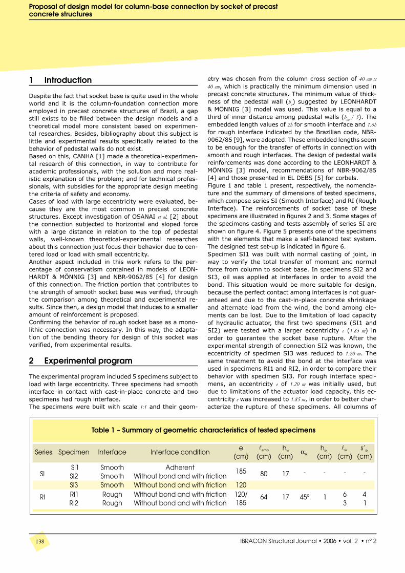
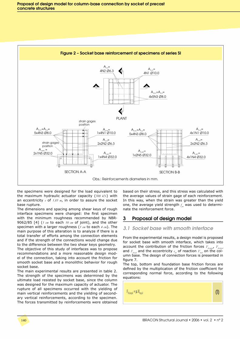
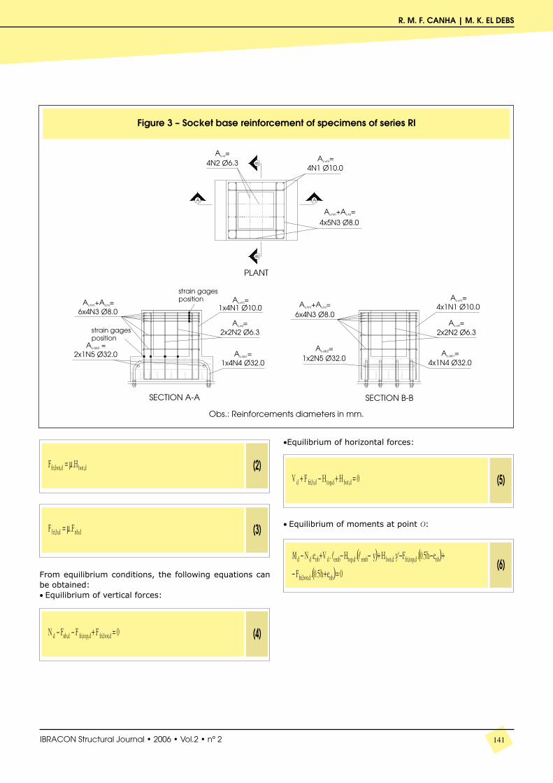
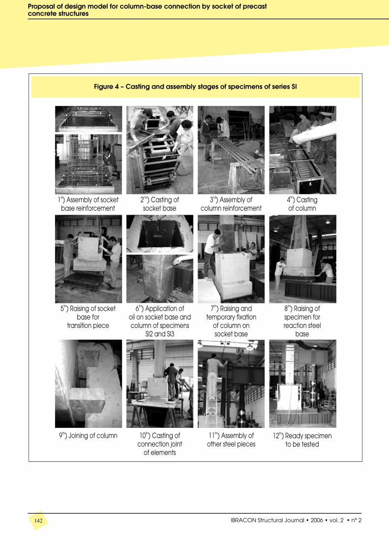
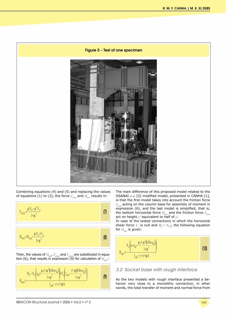
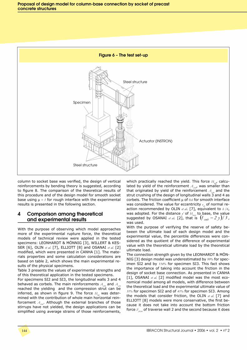
etry was chosen from the column cross section of 40 cm x 40 cm, which is practically the minimum dimension used in precast concrete structures. The minimum value of thick-ness of the pedestal wall (hw) suggested by LEONHARDT & MÖNNIG [3] model was used. This value is equal to a third of inner distance among pedestal walls (hint / 3). The embedded length values of 2h for smooth interface and 1.6h for rough interface indicated by the Brazilian code, NBR-9062/85 [9], were adopted. These embedded lengths seem to be enough for the transfer of efforts in connection with smooth and rough interfaces. The design of pedestal walls reinforcements was done according to the LEONHARDT & MÖNNIG [3] model, recommendations of NBR-9062/85 [4] and those presented in EL DEBS [5] for corbels.Figure 1 and table 1 present, respectively, the nomencla-ture and the summary of dimensions of tested specimens, which compose series SI (Smooth Interface) and RI (Rough Interface). The reinforcements of socket base of these specimens are illustrated in figures 2 and 3. Some stages of the specimens casting and tests assembly of series SI are shown on figure 4. Figure 5 presents one of the specimens with the elements that make a self-balanced test system. The designed test set-up is indicated in figure 6.Specimen SI1 was built with normal casting of joint, in way to verify the total transfer of moment and normal force from column to socket base. In specimens SI2 and SI3, oil was applied at interfaces in order to avoid the bond. This situation would be more suitable for design, because the perfect contact among interfaces is not guar-anteed and due to the cast-in-place concrete shrinkage and alternate load from the wind, the bond among ele-ments can be lost. Due to the limitation of load capacity of hydraulic actuator, the first two specimens (SI1 and SI2) were tested with a larger eccentricity e (1.85 m) in order to guarantee the socket base rupture. After the experimental strength of connection SI2 was known, the eccentricity of specimen SI3 was reduced to 1.20 m. The same treatment to avoid the bond at the interface was used in specimens RI1 and RI2, in order to compare their behavior with specimen SI3. For rough interface speci-mens, an eccentricity e of 1.20 m was initially used, but due to limitations of the actuator load capacity, this ec-centricity e was increased to 1.85 m, in order to better char-acterize the rupture of these specimens. All columns of
139IBRACON Structural Journal • 2006 • Vol.2 • nº 2
R. M. F. CANHA | M. K. EL DEBS
140 IBRACON Structural Journal • 2006 • vol. 2 • nº 2
Proposal of design model for column-base connection by socket of precastconcrete structures
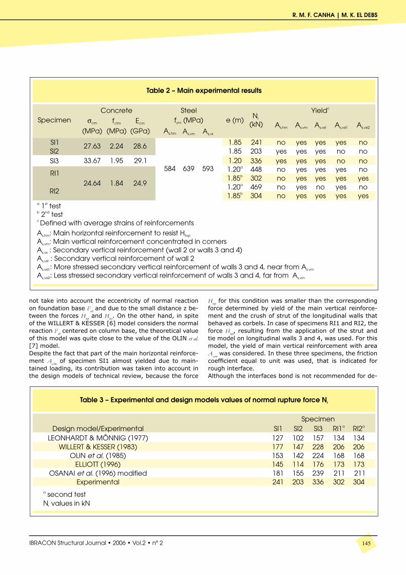
the specimens were designed for the load equivalent to the maximum hydraulic actuator capacity (500 kN) with an eccentricity e of 1.85 m, in order to assure the socket base rupture.The dimensions and spacing among shear keys of rough interface specimens were changed: the first specimen with the minimum roughness recommended by NBR-9062/85 [4] (1 cm to each 10 cm of joint), and the other specimen with a larger roughness (1 cm to each 4 cm). The main purpose of this alteration is to analyze if there is a total transfer of efforts among the connection elements and if the strength of the connections would change due to the difference between the two shear keys geometry.The objective of this study of interfaces was to propose recommendations and a more reasonable design mod-el of the connection, taking into account the friction for smooth socket base and a monolithic behavior for rough socket base.The main experimental results are presented in table 2. The strength of the specimens was determined by the ultimate load resisted by socket base, since the column was designed for the maximum capacity of actuator. The rupture of all specimens occurred with the yielding of main vertical reinforcements and the yielding of second-ary vertical reinforcements, according to the specimen. The forces transmitted by reinforcements were obtained
based on their stress, and this stress was calculated with the average values of strain gage of each reinforcement. In this way, when the strain was greater than the yield one, the average yield strength fym was used to determi-nate the reinforcement force.
3 Proposal of design model
3.1 Socketbasewithsmoothinterface
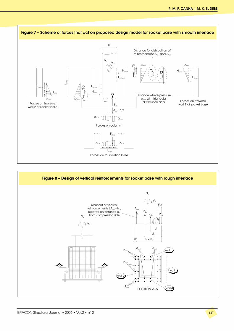
From the experimental results, a design model is proposed for socket base with smooth interface, which takes into account the contribution of the friction forces Ffri,top,d, Ffri,bot,d
and Ffri,b,d and the eccentricity enb of reaction Fnb,d on the col-umn base. The design of connection forces is presented in figure 7.The top, bottom and foundation base friction forces are defined by the multiplication of the friction coefficient for corresponding normal force, according to the following equations:
141IBRACON Structural Journal • 2006 • Vol.2 • nº 2
R. M. F. CANHA | M. K. EL DEBS
From equilibrium conditions, the following equations can be obtained:• Equilibrium of vertical forces:
•Equilibrium of horizontal forces:
• Equilibrium of moments at point O:
142 IBRACON Structural Journal • 2006 • vol. 2 • nº 2
Proposal of design model for column-base connection by socket of precastconcrete structures
143IBRACON Structural Journal • 2006 • Vol.2 • nº 2
R. M. F. CANHA | M. K. EL DEBS
Combining equations (4) and (5) and replacing the values of equations (1) to (3), the force Ffri,b,d and Hbot,d results in:
Then, the values of Hbot,d, Ffri,top,d and Ffri,bot,d are substituted in equa-tion (6), that results in expression (9) for calculation of Htop,d.:
The main difference of this proposed model related to the OSANAI et al. [2] modified model, presented in CANHA [1], is that the first model takes into account the friction force Ffri,b,d acting on the column base for assembly of moment in expression (6), and the last model is simplified, that is, the bottom horizontal force Hbot,d and the friction force Ffri,b,d act on height y” equivalent to half of y’.In case of the tested connections in which the horizontal shear force Vd is null and Md = Nd.e, the following equation for Htop,d is given:
3.2 Socketbasewithroughinterface
As the two models with rough interface presented a be-havior very close to a monolithic connection, in other words, the total transfer of moment and normal force from
144 IBRACON Structural Journal • 2006 • vol. 2 • nº 2
Proposal of design model for column-base connection by socket of precastconcrete structures
column to socket base was verified, the design of vertical reinforcements by bending theory is suggested, according to figure 8. The comparison of the theoretical results of this procedure and of the design model for smooth socket base using µ = 1 for rough interface with the experimental results is presented in the following section.
4 Comparison among theoretical and experimental results
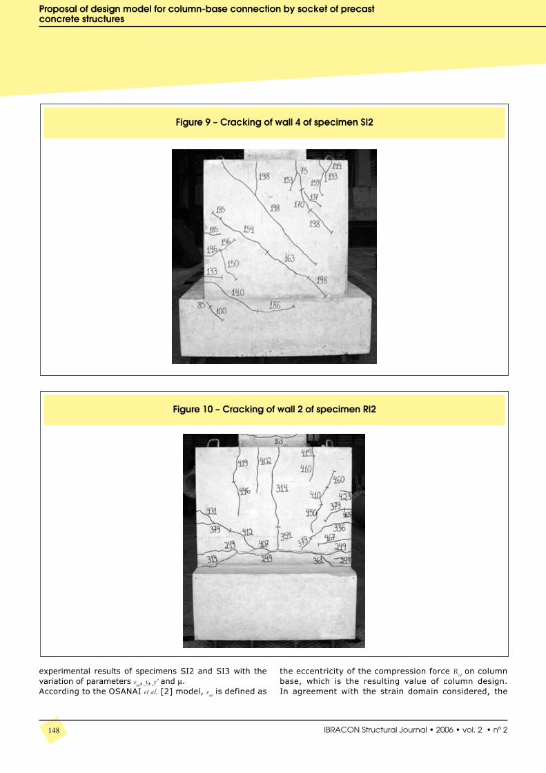
With the purpose of observing which model approaches more of the experimental rupture force, the theoretical models of technical review were applied in the tested specimens: LEONHARDT & MÖNNIG [3], WILLERT & KES-SER [6], OLIN et al. [7], ELLIOTT [8] and OSANAI et al. [2] modified, which were presented in CANHA [1]. The mate-rials properties and some calculation considerations are based on table 2, which shows the main experimental re-sults of the physical specimens.Table 3 presents the values of experimental strengths and of this theoretical application in the tested specimens.For specimens SI2 and SI3, the longitudinal walls 3 and 4 behaved as corbels. The main reinforcements As,hm and As,vm reached the yielding and the compression strut can be inferred, as shown in figure 9. The force Htop was deter-mined with the contribution of whole main horizontal rein-forcement As,hm. Although the external branches of those stirrups have not yielded, the design applications can be simplified using average strains of those reinforcements,
which practically reached the yield. This force Htop, calcu-lated by yield of the reinforcement As,hm, was smaller than that originated by yield of the reinforcement As,vm and the strut crushing of the design of longitudinal walls 3 and 4 as corbels. The friction coefficient µ of 0.6 for smooth interface was considered. The value for eccentricity enb of normal re-action recommended by OLIN et al. [7], equivalent to h /6, was adopted. For the distance y’ of Hbot,d to base, the value suggested by OSANAI et al. [2], that is ( ) 3/y2emb −l , was used.With the purpose of verifying the reserve of safety be-tween the ultimate load of each design model and the experimental value, the percentile differences were con-sidered as the quotient of the difference of experimental value with the theoretical ultimate load by the theoretical ultimate load.The connection strength given by the LEONHARDT & MÖN-NIG [3] design model was underestimated by 99% for spec-imen SI2 and by 114% for specimen SI3. This fact shows the importance of taking into account the friction in the design of socket base connection. As presented in CANHA [1], OSANAI et al. [2] modified model was the most eco-nomical model among all models, with difference between the theoretical load and the experimental ultimate value of 31% for specimen SI2 and of 41% for specimen SI3. Among the models that consider friction, the OLIN et al. [7] and ELLIOTT [8] models were more conservative, the first be-cause it does not take into account the bottom friction force Ffri,bot of traverse wall 2 and the second because it does
145IBRACON Structural Journal • 2006 • Vol.2 • nº 2
R. M. F. CANHA | M. K. EL DEBS
not take into account the eccentricity of normal reaction on foundation base Fnb and due to the small distance z be-tween the forces Htop and Hbot. On the other hand, in spite of the WILLERT & KESSER [6] model considers the normal reaction Fnb centered on column base, the theoretical value of this model was quite close to the value of the OLIN et al. [7] model.Despite the fact that part of the main horizontal reinforce-ment As,hm of specimen SI1 almost yielded due to main-tained loading, its contribution was taken into account in the design models of technical review, because the force
Htop for this condition was smaller than the corresponding force determined by yield of the main vertical reinforce-ment and the crush of strut of the longitudinal walls that behaved as corbels. In case of specimens RI1 and RI2, the force Htop, resulting from the application of the strut and tie model on longitudinal walls 3 and 4, was used. For this model, the yield of main vertical reinforcement with area As,vm was considered. In these three specimens, the friction coefficient equal to unit was used, that is indicated for rough interface.Although the interfaces bond is not recommended for de-
146 IBRACON Structural Journal • 2006 • vol. 2 • nº 2
Proposal of design model for column-base connection by socket of precastconcrete structures
sign of socket bases, the theoretical calculation of specimen SI1 was executed in order to illustrate its safety reserve related to specimen SI2 without bond. As the rupture of specimens RI1 and RI2 was characterized in second test, the calculation of theoretical strength was made with an eccentricity equivalent to 1.85 m of the second test.The correlation among the experimental and theoretical values of specimen SI1 for all analyzed design models was very close of the correlation regarding specimen SI2, which was tested with the same eccentricity. The safety reserve of specimen SI1 related to SI2 for the OSANAI et al. [2] modi-fied model was 17%, while this correlation in experimental values was about 19%. Consequently, if the characteristics of specimen SI1 were used for design, the OSANAI et al. [2] modified model, which supplied better results, could be ap-plied with friction coefficient µ equal to the unit.
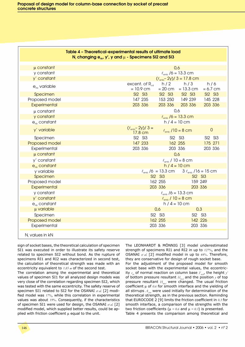
The LEONHARDT & MÖNNIG [3] model underestimated strength of specimens RI1 and RI2 in up to 127%, and the OSANAI et al. [2] modified model in up to 44%. Therefore, they are conservative for design of rough socket base.For the adjustment of the proposed model for smooth socket base with the experimental values, the eccentric-ity enb of normal reaction on column base Fnb,d, the height y’ of bottom pressure resultant Hbot,d and the position y of top pressure resultant Htop,d were changed. The usual friction coefficient µ of 0.6 for smooth interface and the yielding of all stirrups As,hm were used initially for determination of the theoretical strength, as in the previous section. Reminding that EUROCODE 2 [9] limits the friction coefficient in 0.3 for smooth interface, a comparison of the strengths with the two friction coefficients (µ = 0.6 and µ = 0.3) is presented.Table 4 presents the comparison among theoretical and
147IBRACON Structural Journal • 2006 • Vol.2 • nº 2
R. M. F. CANHA | M. K. EL DEBS
148 IBRACON Structural Journal • 2006 • vol. 2 • nº 2
Proposal of design model for column-base connection by socket of precastconcrete structures
the eccentricity of the compression force Rcd on column base, which is the resulting value of column design. In agreement with the strain domain considered, the
experimental results of specimens SI2 and SI3 with the variation of parameters enb, y, y’ and µ.According to the OSANAI et al. [2] model, enb is defined as
149IBRACON Structural Journal • 2006 • Vol.2 • nº 2
R. M. F. CANHA | M. K. EL DEBS
position of neutral axis changes. In other words, for usual and more economical design, for instance, in lim-it between domains 3 and 4, the eccentricity is smaller than that regarding the domain 3 or 2. In specimens where bond was removed, the position of the compres-sion resultant might have changed in function of the slip among column, joint and socket base. However, in safety side, the enb value resulting from the column design between domains 3 and 4 was adopted initially. Other enb values in function of the height h of column section were also attributed for adjustment of the pro-posed model. Naturally, the possible maximum eccen-tricity enb for cases of simple bending and bending-com-pression, considering as the position of Rcd in column design, is equivalent to h / 2.According to table 4, for enb calculated as the position of the compression force Rcd of column design, a difference of 38% and 43% is observed for specimens SI2 and SI3, respec-tively, with the experimental values. As the enb value de-creases, the proposed theoretical model becomes more conservative. In case of enb = h / 2, a larger proximity among theoretical and experimental results was verified, with an excess in the proposed model of 33% for specimen SI2 and 34% for specimen SI3. The value enb = h / 6 suggested by OLIN et al. [7] seems be quite conservative for cases of large eccentricity ( h2e ≥ ) and this is more suitable for average eccentricity ( ). As the position enb of he compression force Rcd resulting from column design for the limit between strain domains 3 and 4 is about h / 4, this value for enb is recommended.Adopting enb = h / 4, then, the height y’ of the resultant of top pressures Htop,d was changed to the values recommended by OSANAI et al. [2], OLIN et al. [7] and zero. As expected, as y’ decreased, the theoretical force approached more of the experimental value. For the more conservative y’ value, the differences between the experimental ultimate load and the value calculated by the proposed model were 38% and 44% for specimens SI2 and SI3, respectively. Despite the fact that the bottom compression force Hbot,d is absorbed directly by the foundation base due to its small height in relation to the base, a value different from zero is more careful for design of socket base, in order to embrace the whole interval of large eccentricity ( h2e ≥ ). The value recommended by OLIN et al. [7] y’ = lemb / 10 is suggested in this work. In this case, the differences between the pro-posed model and the experimental value were 25% and 32%, respectively, for specimens SI2 and SI3.If the compression stresses on traverse wall 1 with para-bolic distribution are considered instead of the stresses with triangular distribution, the position of resultant Htop,d acting on the height of geometric center of these stresses changes from y = lemb / 6 to y = 3lemb / 16, still distancing more the theoretical strength of the experimental result, as ta-ble 4 indicates. In case of y = 3lemb / 16 for the proposed mod-el, the differences in relation to the experimental ultimate load were 28% and 35%, respectively, for specimens SI2 and SI3, against 25% and 32% for y = lemb / 6. This value of y = lemb / 6 is then suggested; however, the reinforcement As,hm continues being distributed evenly along the top region of
height equal to lemb / 3, where the largest concentration of tensions occurs.With the analysis of variation of the friction coefficient, the value of µ = 0.3 supplied strengths with differences of 43% and 49%, respectively, for the experimental results of spec-imens SI2 and SI3, against the percentile values of 25% and 32% with µ = 0.6. The friction coefficient of 0.3 indicates more conservative values. In compensation, the usual val-ue of 0.6 for friction coefficient results in a smaller amount of reinforcement. In case of metallic forms, in which the friction on interfaces is more reduced, µ = 0.3 can be used; while for wooden forms or similar forms, µ = 0.6 seems to be more reasonable.Based on those results, with the known efforts Md, Nd and Vd on column, expressions (9) and (10) are recommended for the design of socket base with smooth interface, using the parameters enb = h / 4, y = lemb / 6, y’ = lemb / 10 and µ ac-cording to the form material of the connection elements. These values are appropriate for cases in which the em-bedded length is not smaller than the value suggested by NBR-9062/85 [4], which was 2h for this case.This model should be applied for cases of large eccentrici-ty, in which the predominant action of moment about axial force tends to generate the friction force Ffri,b,d on the foun-dation base with the same direction of Hbot,d, and the friction force Ffri,bot,d at transverse wall 2 with upward direction and at the column with downward direction, as showed in fig-ure 7. For small eccentricity e, the proposed equation could be used after an experimental investigation, and the cor-rect directions of the friction forces Ffri,bot,d and Ffri,b,d should be analyzed, which can be influenced by the relation among the efforts Md, Vd and Nd and by the geometry.For socket base with smooth interface, the design of the main vertical reinforcement As,vm and the verification of the compression strength should be made considering the longitudinal walls 3 and 4 as corbels according to the LE-ONHARDT & MÖNNIG [3] model. Although the secondary horizontal reinforcement As,hs and the secondary vertical reinforcement As,vst and As,vsl are little requested, they are in-dispensable for cracking control and combat of secondary efforts. They should be calculated according to the corbel recommendations.In the case of specimens of RI series, the monolithic strength of the connection was calculated by bending the-ory, in other words, with the total transfer of moment and of axial force. The value of σcm of the socket base concrete and a parabolic-rectangular distribution of stresses were considered in the calculation of the compression resultant of concrete. As the neutral axis was located in the domain 2a, with the maximum shortened concrete smaller than 2o/oo, only the space equivalent to the stresses diagram with parabolic distribution was considered and the contri-bution of the compressed reinforcement was neglectful. The proposed model with the parameters 1=µ , enb = h / 4, y = 3lemb / 20
(= 0.15 lemb ), and y = lemb / 10 was also applied in
these specimens, just to show the conservatism of this model for rough socket base when compared with the con-nection strength calculated with the yielding of the vertical reinforcements.
150 IBRACON Structural Journal • 2006 • vol. 2 • nº 2
Proposal of design model for column-base connection by socket of precastconcrete structures
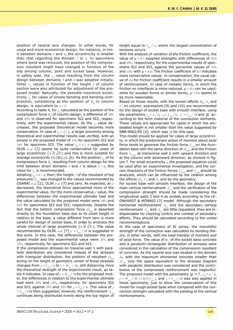
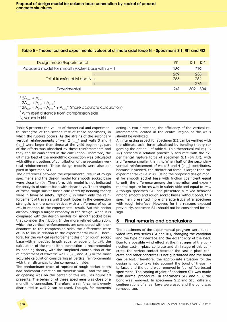
Table 5 presents the values of theoretical and experimen-tal strengths of the second test of these specimens, in which the rupture occurs. As the strains of the secondary vertical reinforcements of wall 2 (As,vst) and walls 3 and 4 (As,vsl) were larger than those at the yield beginning, part of the efforts was absorbed by these reinforcements and they can be considered in the calculation. Therefore, the ultimate load of the monolithic connection was calculated with different options of contribution of the secondary ver-tical reinforcement. These design models were also ap-plied in specimen SI1.The differences between the experimental result of rough specimens and the design model for smooth socket base were close to 40%. Therefore, this model is not indicated for analysis of socket base with shear keys. The strengths of these rough socket bases calculated by bending theory were in favor of safety. Option a, in which only the rein-forcement of traverse wall 2 contributes in the connection strength, is more conservative, with a difference of up to 28% in relation to the experimental result. But this option already brings a larger economy in the design, when it is compared with the design models for smooth socket base that consider the friction. In the more refined calculation, which the vertical reinforcements are considered with their distances to the compression side, the differences were of up to 10% in relation to the experimental value. There-fore, for the vertical reinforcement design of rough socket base with embedded length equal or superior to 1.6h, the calculation of the monolithic connection is recommended by bending theory, with the simplified contribution of the reinforcement of traverse wall 2 (As,vm and As,vst) or the most accurate calculation considering all vertical reinforcements with their distances to the compression side.The predominant crack of rupture of rough socket bases had horizontal direction on traverse wall 2 and the larg-er opening was on the center of this wall, as figure 10 presents. The behavior of these specimens was close of a monolithic connection. Therefore, a reinforcement evenly distributed in wall 2 can be used. Though, for moments
acting in two directions, the efficiency of the vertical re-inforcements located in the central region of the walls should be analyzed.An interesting aspect for specimen SI1 can be verified with the ultimate axial force calculated by bending theory re-garding the option a of table 5. This theoretical value (239 kN) presents a relation practically accurate with the ex-perimental rupture force of specimen SI1 (241 kN), with a difference smaller than 1%. When half of the secondary vertical reinforcement of walls 3 and 4 (As,vsl1) contributes, because it yielded, the theoretical force is larger than the experimental value in 8%. Using the proposed design mod-el for smooth socket base with friction coefficient equal to unit, the difference among the theoretical and experi-mental rupture forces was in safety side and equal to 28%. Although specimen SI1 has presented a mixed behavior among smooth and rough socket bases without bond, this specimen presented more characteristics of a specimen with rough interface. However, for the reasons exposed previously, specimen SI1 should not be considered for de-sign.
5 Final remarks and conclusions
The specimens of the experimental program were subdi-vided into two series (SI and RI), changing the condition and the type of interface and the eccentricity of the load. Due to a possible wind effect at the first ages of the con-nection cast-in-place concrete and shrinkage of this con-crete, the perfect contact between the cast-in-place con-crete and other concretes is not guaranteed and the bond can be lost. Therefore, the appropriate situation for the design is not to take into account the bond of these in-terfaces and the bond was removed in four of five tested specimens. The casting of joint of specimen SI1 was made with normal procedure. In specimens SI2 and SI3, the bond was removed. In specimens SI2 and SI3, different configurations of shear keys were used and the bond was removed too.
151IBRACON Structural Journal • 2006 • Vol.2 • nº 2
R. M. F. CANHA | M. K. EL DEBS
Based on the experimental results, some recommenda-tions and more consistent models were suggested for de-sign of the reinforcements and verification of the concrete strength of pedestal walls:a) According to the experimental results of specimens SI2 and SI3, without bond on interfaces, the transfer of the efforts of traverse wall 1 for longitudinal walls 3 and 4 oc-curred together with the action of the friction forces and the behavior of these longitudinal walls as corbels. This corbel behavior was according to the LEONHARDT & MÖN-NIG [3] model, with the indirect transmission of the force Htop, that resulted in the resistant mechanism of the com-pression strut of concrete and of the tension in tie. How-ever, the secondary vertical reinforcement of wall 3 and 4 As,vsl was little requested.b) The model proposed in this paper for design of the re-inforcement As,hm provided good results, with differences of 25% and 32%, at the safe side, for specimens SI2 and SI3, respectively, when µ = 0.6 was used. This model should be used for smooth socket base with the embedded length equal or longer than 2h. After the calculation of As,hm, the design of longitudinal walls 3 and 4 as corbels is indicated, that results in the design of the reinforcement As,vm and the verification of crushing of the concrete compression strut.c) Besides the indication of parameters enb = h / 4, y = lemb / 6, y’ = lemb / 10 for the proposed design model, the friction coef-ficient is recommended according to the type of form used in the connection building. For forms in which the inter-faces friction is reduced, as the steel moulds, µ = 0.3 is in-dicated; for wooden or similar forms, µ = 0.6 is suggested.d) Although specimens RI1 and RI2 had different configu-rations of shear keys, the experimental strength of these specimens was practically the same. The rupture of these specimens was characterized in the second test with the yielding of the vertical reinforcements and was accompa-nied of a predominant crack of bending on traverse wall 2. As there was the total transfer of efforts from column to pedestal walls, in other words, all stressed vertical rein-forcements (As,vm, As,vst and As,vsl) contributed to the connec-tion strength, specimens RI1 and RI2 with h6.1emb =l presented behavior similar to a monolithic connection. Therefore, the bending theory is more appropriate for de-sign of these vertical reinforcements. However, this is ap-plied for rough socket bases with embedded length not shorter than 1.6h and the roughness must be in the range of this research.
6 Acknowledgements
The authors would like to acknowledge FAPESP, Brazilian government agency, for the academic and the financial support. They are also indebted to Company Gerdau for the donation of the main reinforcement of columns.
7 References
[01] CANHA, R.M.F. Theoretical-experimental analysis of column-foundation connection
through socket of precast concrete structures. São Carlos. 279p. PhD Thesis. Escola de Engenharia de São Carlos, Universidade de São Paulo. 2004. (in Portuguese Estudo teórico-experimental da ligação pilar-fundação por meio de cálice em estruturas de concreto pré-moldado) [02] OSANAI, Y.; WATANABE, F.; OKAMOTO, S. Stress transfer mechanism of socket base connections with precast concrete columns. ACI Structural Journal, v.93, n.3, p.266-276, May/June. 1996. [03] LEONHARDT, F.; MÖNNIG, E. Vorlersungen uber massivabu. Berlin. Springer-Verlag. 1973. (Portuguese version Construções de concreto: Princípios básicos sobre armação de estruturas de concreto armado. v.3, 1.ed. Rio de Janeiro, Interciência. 1977.) [04] ASSOCIAÇÃO BRASILEIRA DE NORMAS TÉCNICAS. NBR 9062 - Design and fabrication of precast concrete structures. Rio de Janeiro, ABNT. 1985. (in Portuguese Projeto e execução de estruturas de concreto pré-moldado) [05] EL DEBS, M.K. Precast concrete: bases and applications. 1.ed. São Carlos, SP, Publicação EESC-USP. 2000. (in Portuguese Concreto pré- moldado: fundamentos e aplicações) [06] WILLERT, O.; KESSER, E. Foundations for bottom-end fixed precast concrete columns. Betonwerk+Fertigteil-Technik, v.49, n.3, p.137-142. 1983. [07] OLIN, J.; HAKKARAINEN, T.; RÄMÄ, M. Connections and Joints between precast concrete units. Espoo, Julkaisija-Utgivare. 1985. [08] ELLIOTT, K.S. Multi-storey precast concrete framed structures. Oxford, Blackwell Science. 1996. [09] COMITÉ EUROPEO DE NORMALIZACIÓN. Eurocódigo 2 - Proyecto de estructuras de homigón - Parte 1-3: Reglas generales. Elementos y estructuras. Prefabricados de hormigón. Madrid, AENOR. 1995. (Eurocode 2)