Embed Size (px)
Citation preview
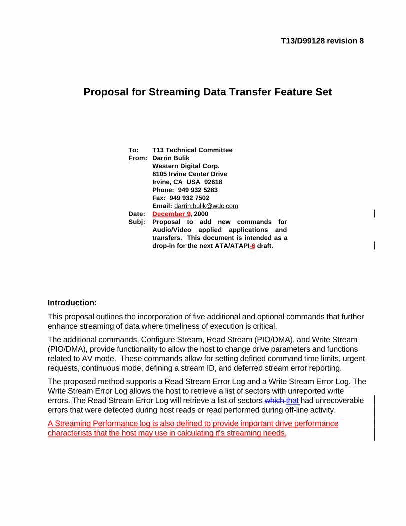
T13/D99128 revision 8
Proposal for Streaming Data Transfer Feature Set
To: T13 Technical CommitteeFrom: Darrin Bulik
Western Digital Corp. 8105 Irvine Center DriveIrvine, CA USA 92618Phone: 949 932 5283Fax: 949 932 7502Email: [email protected]
Date: December 9, 2000Subj: Proposal to add new commands for
Audio/Video applied applications andtransfers. This document is intended as adrop-in for the next ATA/ATAPI-6 draft.
Introduction:
This proposal outlines the incorporation of five additional and optional commands that furtherenhance streaming of data where timeliness of execution is critical.
The additional commands, Configure Stream, Read Stream (PIO/DMA), and Write Stream(PIO/DMA), provide functionality to allow the host to change drive parameters and functionsrelated to AV mode. These commands allow for setting defined command time limits, urgentrequests, continuous mode, defining a stream ID, and deferred stream error reporting.
The proposed method supports a Read Stream Error Log and a Write Stream Error Log. TheWrite Stream Error Log allows the host to retrieve a list of sectors with unreported writeerrors. The Read Stream Error Log will retrieve a list of sectors which that had unrecoverableerrors that were detected during host reads or read performed during off-line activity.
A Streaming Performance log is also defined to provide important drive performancecharacterists that the host may use in calculating it’s streaming needs.
T13/D99128 revision 8
Page 2
STREAMING COMMAND SET (Proposal)
Change History
r8 10/17/00 – Updated to include input from October T13 Plenary Meeting
r7 9/18/00 – Updated to include input from August T13 Plenary Meeting.
r6 7/2/00 – Updated with input from June T13 Meeting, E00124r0 and E00125r0.
r5 6/21/00 – Updated with input from April T13 Meeting and D99123r3.
r4 4/18/00 – Updated to incorporate Ax+B Streaming command capability.
r3 3/16/00 - Updated to include input from February T13 Plenary
r2 2/22/00 - Updated to include input from December T13 Plenary
r1 11/29/99 – Updated to include input from October T13 Plenary
T13/D99128 revision 8
Page 3
3.1 Definitions and Abbreviations
Add:Audio-Video: Audio-Video (AV) applications utilize data that is related to video images and/or audio. Thedistinguishing characteristic of this type of data is that accuracy is of lower priority than timely transfer of thedata.
8.12 Definitions and value ranges of IDENTIFY DEVICE words
Add:The content of words TBD2 and TBD3 may be affected by the host issuing a SET FEATURES subcommand42h, C2h and 43h (Automatic Acoustic Management, and Typical Host Interface Sector Time).
8.37 SET FEATURES
Add to subcommand 42h and C2h description:Upon completion of Set Features subcommands 42h and C2h, the device may update word TBD2 and TBD3 inIdentify Device, and the contents of the Stream Performance Parameters Log in the SMART Read StreamingLog command.
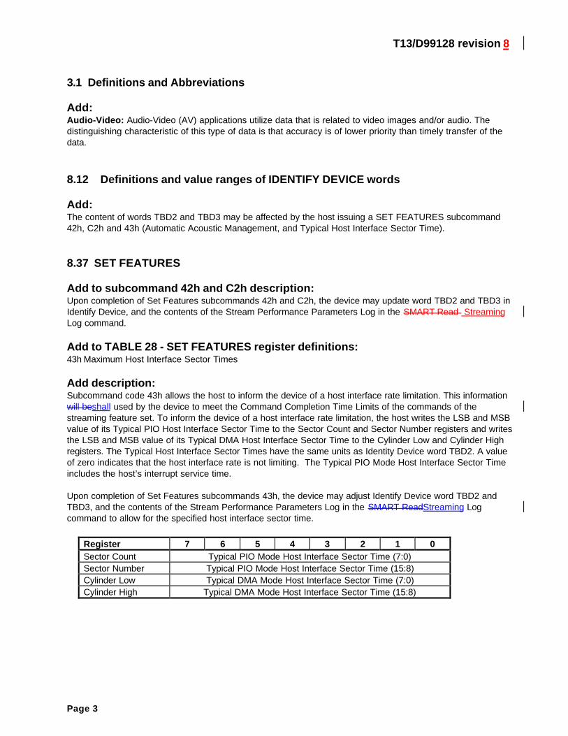
Add to TABLE 28 - SET FEATURES register definitions:43h Maximum Host Interface Sector Times
Add description:Subcommand code 43h allows the host to inform the device of a host interface rate limitation. This informationwill beshall used by the device to meet the Command Completion Time Limits of the commands of thestreaming feature set. To inform the device of a host interface rate limitation, the host writes the LSB and MSBvalue of its Typical PIO Host Interface Sector Time to the Sector Count and Sector Number registers and writesthe LSB and MSB value of its Typical DMA Host Interface Sector Time to the Cylinder Low and Cylinder Highregisters. The Typical Host Interface Sector Times have the same units as Identity Device word TBD2. A valueof zero indicates that the host interface rate is not limiting. The Typical PIO Mode Host Interface Sector Timeincludes the host’s interrupt service time.
Upon completion of Set Features subcommands 43h, the device may adjust Identify Device word TBD2 andTBD3, and the contents of the Stream Performance Parameters Log in the SMART ReadStreaming Logcommand to allow for the specified host interface sector time.
Register 7 6 5 4 3 2 1 0Sector Count Typical PIO Mode Host Interface Sector Time (7:0)Sector Number Typical PIO Mode Host Interface Sector Time (15:8)Cylinder Low Typical DMA Mode Host Interface Sector Time (7:0)Cylinder High Typical DMA Mode Host Interface Sector Time (15:8)
T13/D99128 revision 8
Page 4
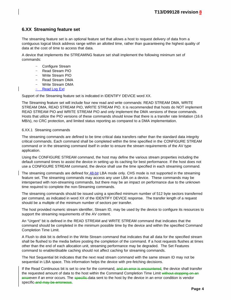
6.XX Streaming feature set
The streaming feature set is an optional feature set that allows a host to request delivery of data from acontiguous logical block address range within an allotted time, rather than guaranteeing the highest quality ofdata at the cost of time to access that data.
A device that implements the STREAMING feature set shall implement the following minimum set ofcommands:
− Configure Stream− Read Stream PIO− Write Stream PIO− Read Stream DMA− Write Stream DMA− Read Log Ext
Support of the Streaming feature set is indicated in IDENTIFY DEVICE word XX.
The Streaming feature set will include four new read and write commands: READ STREAM DMA, WRITESTREAM DMA, READ STREAM PIO, WRITE STREAM PIO. It is recommended that hosts do NOT implementREAD STREAM PIO and WRITE STREAM PIO and only implement the DMA versions of these commands.Hosts that utilize the PIO versions of these commands should know that there is a transfer rate limitation (16.6MB/s), no CRC protection, and limited status reporting as compared to a DMA implementation.
6.XX.1 Streaming commands
The streaming commands are defined to be time critical data transfers rather than the standard data integritycritical commands. Each command shall be completed within the time specified in the CONFIGURE STREAMcommand or in the streaming command itself in order to ensure the stream requirements of the AV typeapplication.
Using the CONFIGURE STREAM command, the host may define the various stream properties including thedefault command times to assist the device in setting up its caching for best performance. If the host does notuse a CONFIGURE STREAM command, the device shall use the time specified in each streaming command.
The streaming commands are defined for 48-bit LBA mode only. CHS mode is not supported in the streamingfeature set. The streaming commands may access any user LBA on a device. These commands may beinterspersed with non-streaming commands, but there may be an impact on performance due to the unknowntime required to complete the non-Streaming commands.
The streaming commands should be issued using a specified minimum number of 512 byte sectors transferredper command, as indicated in word XX of the IDENTIFY DEVICE response. The transfer length of a requestshould be a multiple of the minimum number of sectors per transfer.
The host provided numeric stream identifier, Stream ID, may be used by the device to configure its resources tosupport the streaming requirements of the AV content.
An “Urgent” bit is defined in the READ STREAM and WRITE STREAM command that indicates that thecommand should be completed in the minimum possible time by the device and within the specified CommandCompletion Time Limit.
A Flush to disk bit is defined in the Write Stream command that indicates that all data for the specified streamshall be flushed to the media before posting the completion of the command. If a host requests flushes at timesother than the end of each allocation unit, streaming performance may be degraded. The Set Featurescommand to enable/disable caching should not affect caching for streaming commands.
The Not Sequential bit indicates that the next read stream command with the same stream ID may not besequential in LBA space. This information helps the device with pre-fetching decisions.
If the Read Continuous bit is set to one for the command, and an error is encountered, the device shall transferthe requested amount of data to the host within the Command Completion Time Limit without stopping on anerroreven if an error occurs. The specific data sent to the host by the device in an error condition is vendorspecific and may be erroneous.
T13/D99128 revision 8
Page 5
If the Write Continuous bit is set to one for the command, and an error is encountered, the device shall transferthe requested amount of data from the host, and shall attempt to write to the media as much of the data aspossible practical without stopping host data transfer on an error. If an error cannot be resolved within theCommand Completion Time Limit, the erroneous section on the media may be unchanged or may containundefined data. A future read of this area may not report an error, even though the data is erroneous.
The Handle Streaming Error bit indicates to the device that this command starts at the LBA of a recentlyreported error section, so the device can may attempt to continue its corresponding error recovery sequencewhere it left off earlier. This mechanism allows the host to schedule error recovery and defect management forcontent critical data.
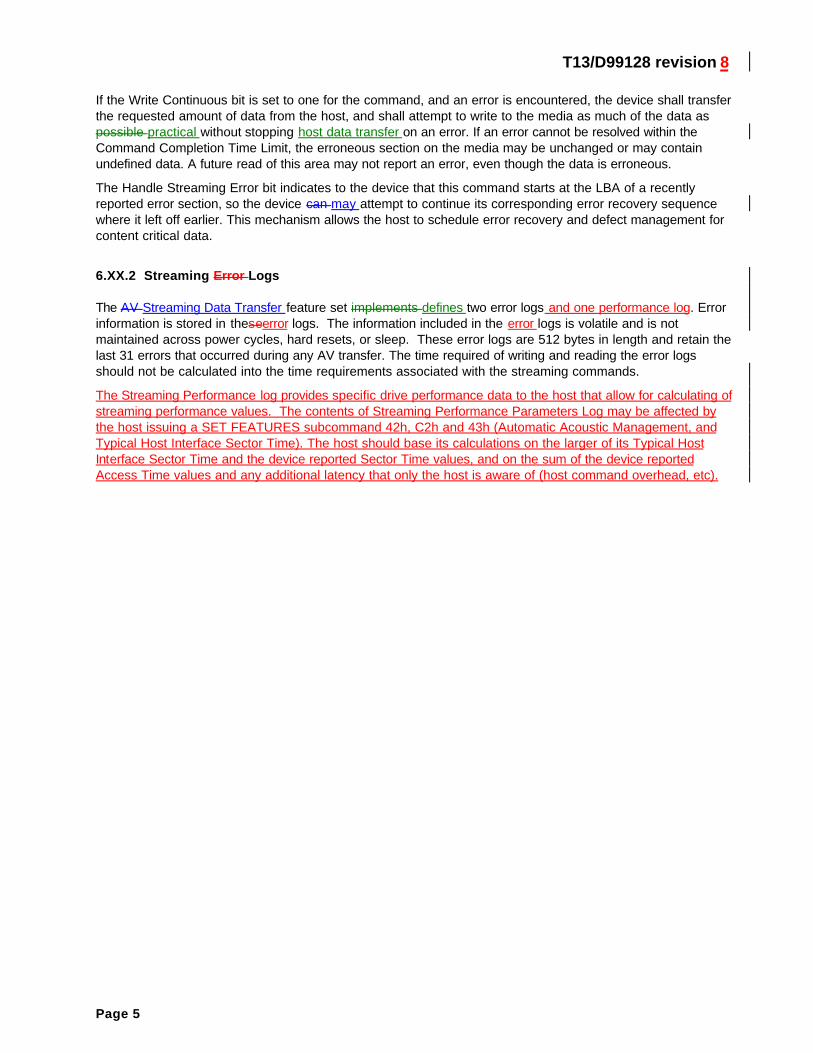
6.XX.2 Streaming Error Logs
The AV Streaming Data Transfer feature set implements defines two error logs and one performance log. Errorinformation is stored in theseerror logs. The information included in the error logs is volatile and is notmaintained across power cycles, hard resets, or sleep. These error logs are 512 bytes in length and retain thelast 31 errors that occurred during any AV transfer. The time required of writing and reading the error logsshould not be calculated into the time requirements associated with the streaming commands.
The Streaming Performance log provides specific drive performance data to the host that allow for calculating ofstreaming performance values. The contents of Streaming Performance Parameters Log may be affected bythe host issuing a SET FEATURES subcommand 42h, C2h and 43h (Automatic Acoustic Management, andTypical Host Interface Sector Time). The host should base its calculations on the larger of its Typical HostInterface Sector Time and the device reported Sector Time values, and on the sum of the device reportedAccess Time values and any additional latency that only the host is aware of (host command overhead, etc).
T13/D99128 revision 8
Page 6
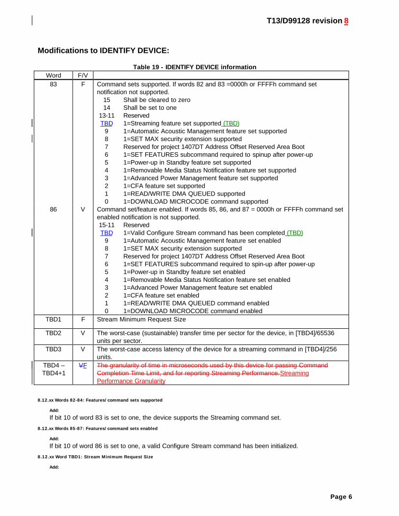
Modifications to IDENTIFY DEVICE:
Table 19 - IDENTIFY DEVICE informationWord F/V
83 F Command sets supported. If words 82 and 83 =0000h or FFFFh command setnotification not supported.
1514
13-11TBD
9876543210
Shall be cleared to zeroShall be set to oneReserved1=Streaming feature set supported (TBD)1=Automatic Acoustic Management feature set supported1=SET MAX security extension supportedReserved for project 1407DT Address Offset Reserved Area Boot1=SET FEATURES subcommand required to spinup after power-up1=Power-up in Standby feature set supported1=Removable Media Status Notification feature set supported1=Advanced Power Management feature set supported1=CFA feature set supported1=READ/WRITE DMA QUEUED supported1=DOWNLOAD MICROCODE command supported
86 V Command set/feature enabled. If words 85, 86, and 87 = 0000h or FFFFh command setenabled notification is not supported.15-11TBD
9876543210
Reserved1=Valid Configure Stream command has been completed (TBD)1=Automatic Acoustic Management feature set enabled1=SET MAX security extension supportedReserved for project 1407DT Address Offset Reserved Area Boot1=SET FEATURES subcommand required to spin-up after power-up1=Power-up in Standby feature set enabled1=Removable Media Status Notification feature set enabled1=Advanced Power Management feature set enabled1=CFA feature set enabled1=READ/WRITE DMA QUEUED command enabled1=DOWNLOAD MICROCODE command enabled
TBD1 F Stream Minimum Request Size
TBD2 V The worst-case (sustainable) transfer time per sector for the device, in [TBD4]/65536units per sector.
TBD3 V The worst-case access latency of the device for a streaming command in [TBD4]/256units.
TBD4 –TBD4+1
VF The granularity of time in microseconds used by this device for passing CommandCompletion Time Limit, and for reporting Streaming Performance.StreamingPerformance Granularity
8.12.xx Words 82-84: Features/command sets supported
Add:If bit 10 of word 83 is set to one, the device supports the Streaming command set.
8.12.xx Words 85-87: Features/command sets enabled
Add:If bit 10 of word 86 is set to one, a valid Configure Stream command has been initialized.
8.12.xx Word TBD1: Stream Minimum Request Size
Add:
T13/D99128 revision 8
Page 7
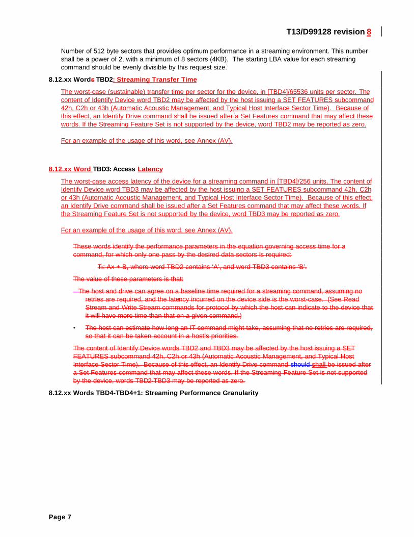
Number of 512 byte sectors that provides optimum performance in a streaming environment. This numbershall be a power of 2, with a minimum of 8 sectors (4KB). The starting LBA value for each streamingcommand should be evenly divisible by this request size.
8.12.xx Words TBD2: Streaming Transfer Time
The worst-case (sustainable) transfer time per sector for the device, in [TBD4]/65536 units per sector. Thecontent of Identify Device word TBD2 may be affected by the host issuing a SET FEATURES subcommand42h, C2h or 43h (Automatic Acoustic Management, and Typical Host Interface Sector Time). Because ofthis effect, an Identify Drive command shall be issued after a Set Features command that may affect thesewords. If the Streaming Feature Set is not supported by the device, word TBD2 may be reported as zero.
For an example of the usage of this word, see Annex (AV).
8.12.xx Word TBD3: Access Latency
The worst-case access latency of the device for a streaming command in [TBD4]/256 units. The content ofIdentify Device word TBD3 may be affected by the host issuing a SET FEATURES subcommand 42h, C2hor 43h (Automatic Acoustic Management, and Typical Host Interface Sector Time). Because of this effect,an Identify Drive command shall be issued after a Set Features command that may affect these words. Ifthe Streaming Feature Set is not supported by the device, word TBD3 may be reported as zero.
For an example of the usage of this word, see Annex (AV).
These words identify the performance parameters in the equation governing access time for acommand, for which only one pass by the desired data sectors is required:
T≤ Ax + B, where word TBD2 contains ‘A’, and word TBD3 contains ‘B’.
The value of these parameters is that:
�The host and drive can agree on a baseline time required for a streaming command, assuming noretries are required, and the latency incurred on the device side is the worst-case. (See ReadStream and Write Stream commands for protocol by which the host can indicate to the device thatit will have more time than that on a given command.)
• The host can estimate how long an IT command might take, assuming that no retries are required,so that it can be taken account in a host’s priorities.
The content of Identify Device words TBD2 and TBD3 may be affected by the host issuing a SETFEATURES subcommand 42h, C2h or 43h (Automatic Acoustic Management, and Typical HostInterface Sector Time). Because of this effect, an Identify Drive command should shall be issued aftera Set Features command that may affect these words. If the Streaming Feature Set is not supportedby the device, words TBD2-TBD3 may be reported as zero.
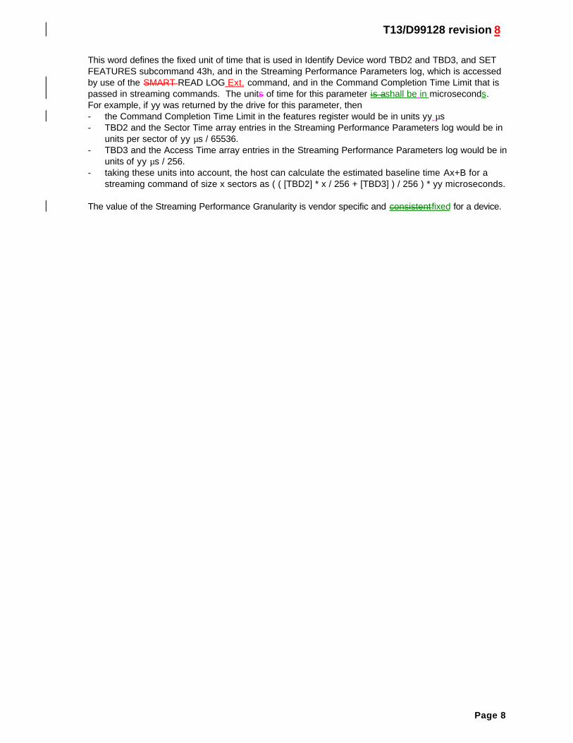
8.12.xx Words TBD4-TBD4+1: Streaming Performance Granularity
T13/D99128 revision 8
Page 8
This word defines the fixed unit of time that is used in Identify Device word TBD2 and TBD3, and SETFEATURES subcommand 43h, and in the Streaming Performance Parameters log, which is accessedby use of the SMART READ LOG Ext. command, and in the Command Completion Time Limit that ispassed in streaming commands. The units of time for this parameter is ashall be in microseconds.For example, if yy was returned by the drive for this parameter, then- the Command Completion Time Limit in the features register would be in units yy µs- TBD2 and the Sector Time array entries in the Streaming Performance Parameters log would be in
units per sector of yy µs / 65536.- TBD3 and the Access Time array entries in the Streaming Performance Parameters log would be in
units of yy µs / 256.- taking these units into account, the host can calculate the estimated baseline time Ax+B for a
streaming command of size x sectors as ( ( [TBD2] * x / 256 + [TBD3] ) / 256 ) * yy microseconds.
The value of the Streaming Performance Granularity is vendor specific and consistentfixed for a device.
T13/D99128 revision 8
Page 9
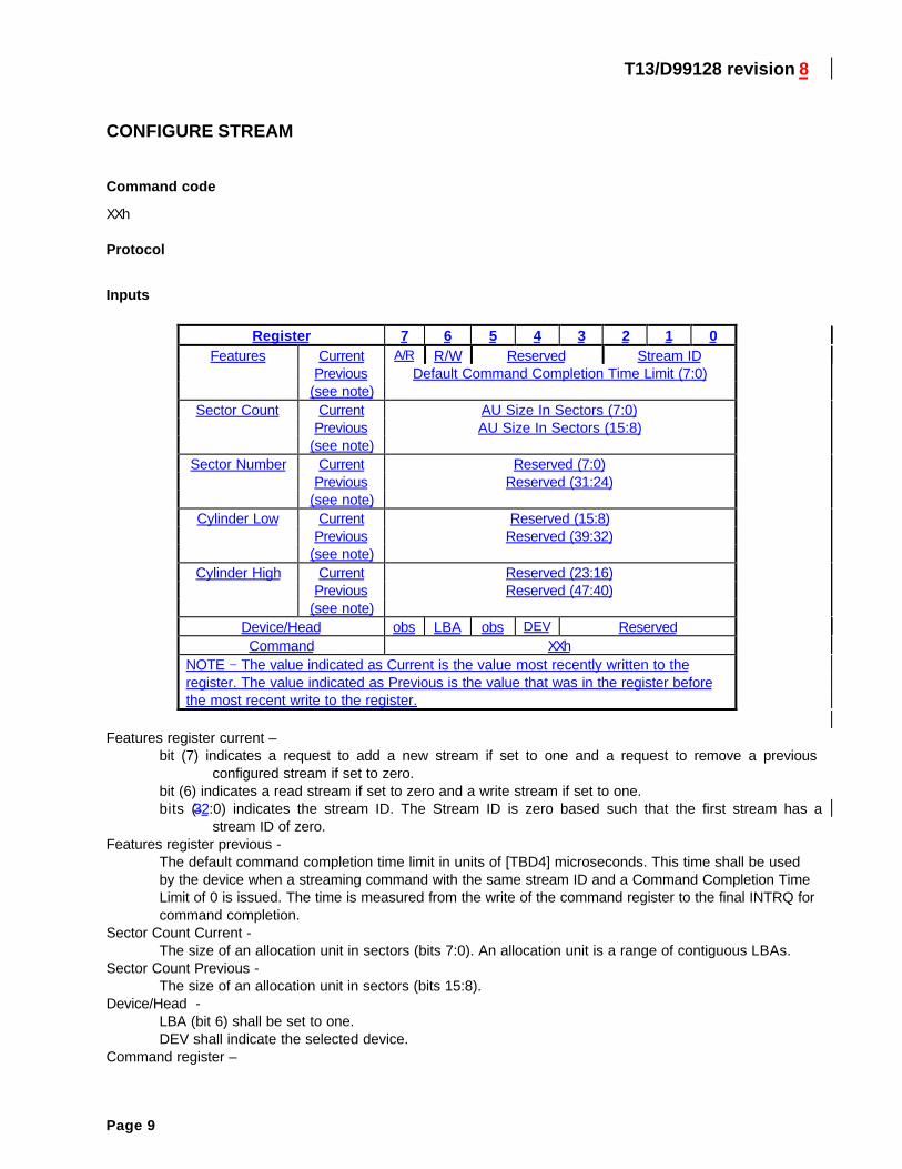
CONFIGURE STREAM
Command code
XXh
Protocol
Inputs
Register 7 6 5 4 3 2 1 0Features Current A/R R/W Reserved Stream ID
Previous Default Command Completion Time Limit (7:0)(see note)
Sector Count Current AU Size In Sectors (7:0)Previous AU Size In Sectors (15:8)
(see note)Sector Number Current Reserved (7:0)
Previous Reserved (31:24)(see note)
Cylinder Low Current Reserved (15:8)Previous Reserved (39:32)
(see note)Cylinder High Current Reserved (23:16)
Previous Reserved (47:40)(see note)
Device/Head obs LBA obs DEV ReservedCommand XXh
NOTE − The value indicated as Current is the value most recently written to theregister. The value indicated as Previous is the value that was in the register beforethe most recent write to the register.
Features register current –bit (7) indicates a request to add a new stream if set to one and a request to remove a previous
configured stream if set to zero.bit (6) indicates a read stream if set to zero and a write stream if set to one.bits (32:0) indicates the stream ID. The Stream ID is zero based such that the first stream has a
stream ID of zero.Features register previous -
The default command completion time limit in units of [TBD4] microseconds. This time shall be usedby the device when a streaming command with the same stream ID and a Command Completion TimeLimit of 0 is issued. The time is measured from the write of the command register to the final INTRQ forcommand completion.
Sector Count Current -The size of an allocation unit in sectors (bits 7:0). An allocation unit is a range of contiguous LBAs.
Sector Count Previous -The size of an allocation unit in sectors (bits 15:8).
Device/Head -LBA (bit 6) shall be set to one.DEV shall indicate the selected device.
Command register –
T13/D99128 revision 8
Page 10
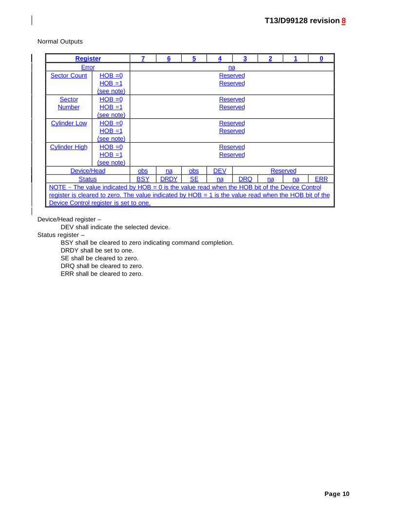
Normal Outputs
Register 7 6 5 4 3 2 1 0Error na
Sector Count HOB =0 ReservedHOB =1 Reserved
(see note)Sector HOB =0 Reserved
Number HOB =1 Reserved(see note)
Cylinder Low HOB =0 ReservedHOB =1 Reserved
(see note)Cylinder High HOB =0 Reserved
HOB =1 Reserved(see note)
Device/Head obs na obs DEV ReservedStatus BSY DRDY SE na DRQ na na ERR
NOTE − The value indicated by HOB = 0 is the value read when the HOB bit of the Device Controlregister is cleared to zero. The value indicated by HOB = 1 is the value read when the HOB bit of theDevice Control register is set to one.
Device/Head register –DEV shall indicate the selected device.
Status register –BSY shall be cleared to zero indicating command completion.DRDY shall be set to one.SE shall be cleared to zero.DRQ shall be cleared to zero.ERR shall be cleared to zero.
T13/D99128 revision 8
Page 11
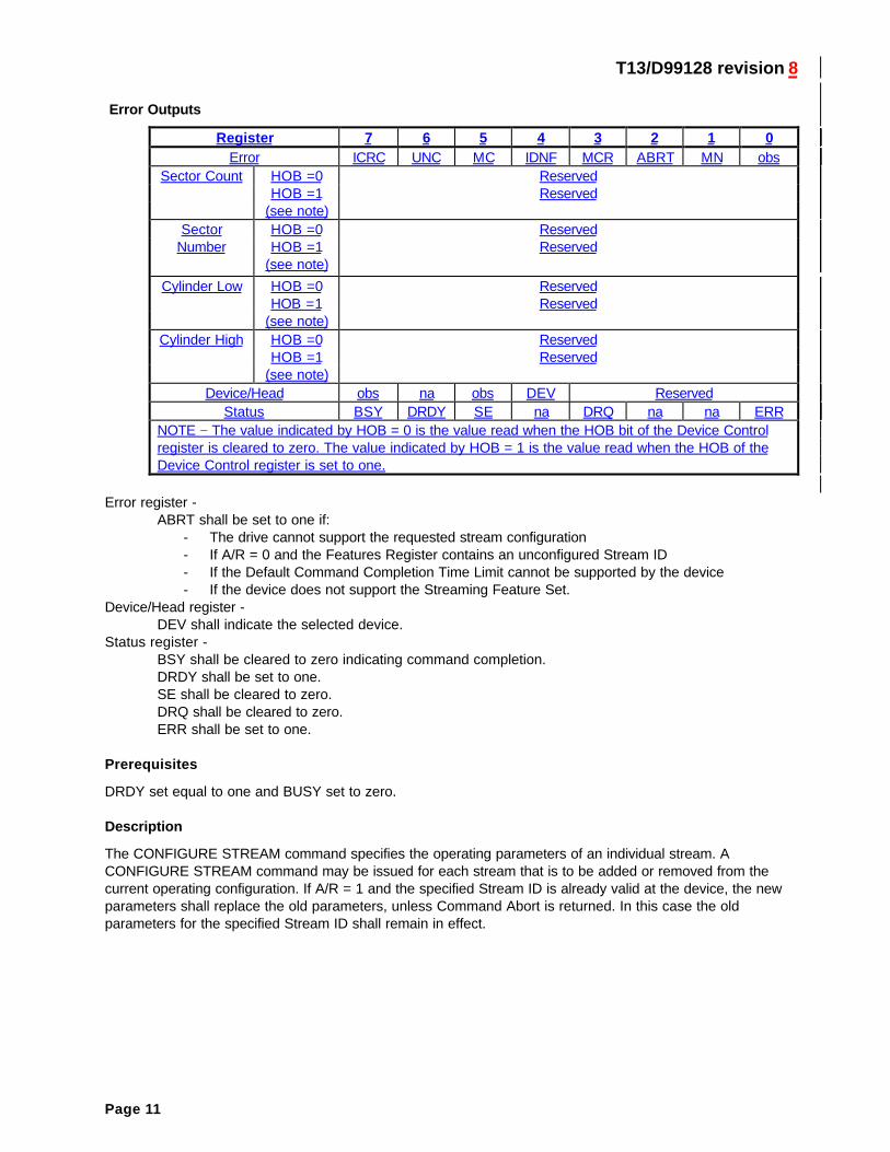
Error Outputs
Register 7 6 5 4 3 2 1 0Error ICRC UNC MC IDNF MCR ABRT MN obs
Sector Count HOB =0 ReservedHOB =1 Reserved
(see note)Sector HOB =0 Reserved
Number HOB =1 Reserved(see note)
Cylinder Low HOB =0 ReservedHOB =1 Reserved
(see note)Cylinder High HOB =0 Reserved
HOB =1 Reserved(see note)
Device/Head obs na obs DEV ReservedStatus BSY DRDY SE na DRQ na na ERR
NOTE − The value indicated by HOB = 0 is the value read when the HOB bit of the Device Controlregister is cleared to zero. The value indicated by HOB = 1 is the value read when the HOB of theDevice Control register is set to one.
Error register -ABRT shall be set to one if:
- The drive cannot support the requested stream configuration- If A/R = 0 and the Features Register contains an unconfigured Stream ID- If the Default Command Completion Time Limit cannot be supported by the device- If the device does not support the Streaming Feature Set.
Device/Head register -DEV shall indicate the selected device.
Status register -BSY shall be cleared to zero indicating command completion.DRDY shall be set to one.SE shall be cleared to zero.DRQ shall be cleared to zero.ERR shall be set to one.
Prerequisites
DRDY set equal to one and BUSY set to zero.
Description
The CONFIGURE STREAM command specifies the operating parameters of an individual stream. ACONFIGURE STREAM command may be issued for each stream that is to be added or removed from thecurrent operating configuration. If A/R = 1 and the specified Stream ID is already valid at the device, the newparameters shall replace the old parameters, unless Command Abort is returned. In this case the oldparameters for the specified Stream ID shall remain in effect.
T13/D99128 revision 8
Page 12
READ STREAM DMA
Command code
XXh
Protocol
DMA (see 9.7)
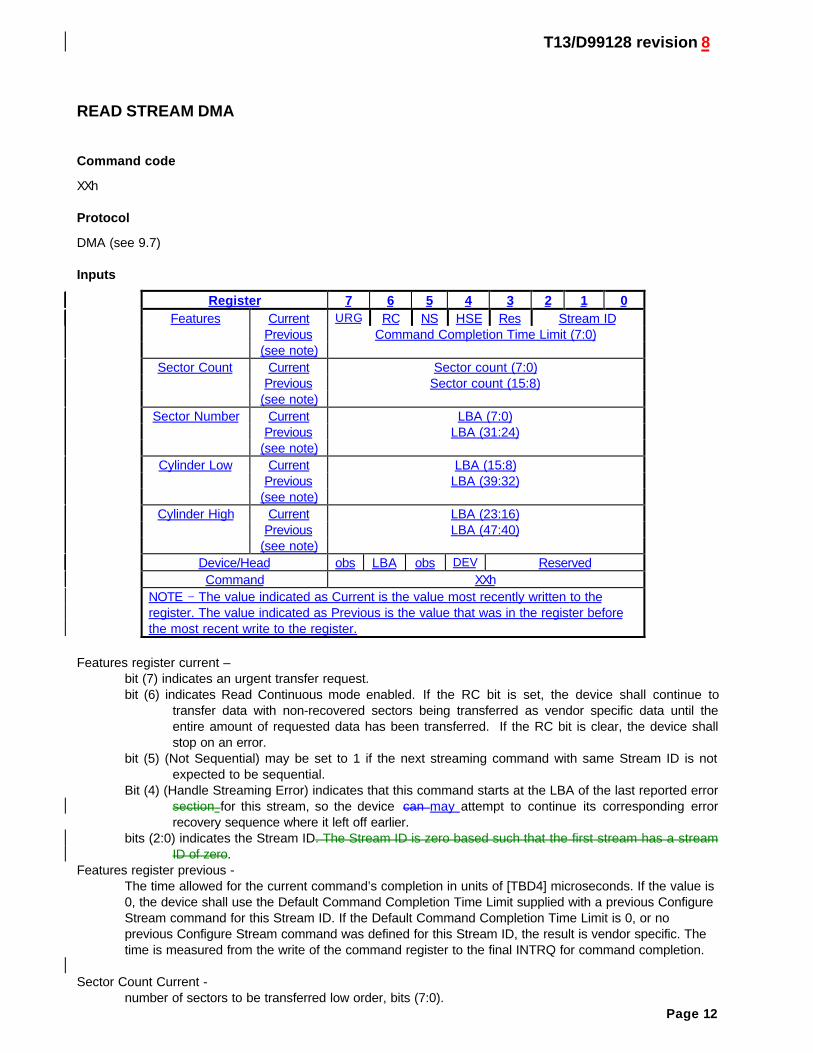
Inputs
Register 7 6 5 4 3 2 1 0Features Current URG RC NS HSE Res Stream ID
Previous Command Completion Time Limit (7:0)(see note)
Sector Count Current Sector count (7:0)Previous Sector count (15:8)
(see note)Sector Number Current LBA (7:0)
Previous LBA (31:24)(see note)
Cylinder Low Current LBA (15:8)Previous LBA (39:32)
(see note)Cylinder High Current LBA (23:16)
Previous LBA (47:40)(see note)
Device/Head obs LBA obs DEV ReservedCommand XXh
NOTE − The value indicated as Current is the value most recently written to theregister. The value indicated as Previous is the value that was in the register beforethe most recent write to the register.
Features register current –bit (7) indicates an urgent transfer request.bit (6) indicates Read Continuous mode enabled. If the RC bit is set, the device shall continue to
transfer data with non-recovered sectors being transferred as vendor specific data until theentire amount of requested data has been transferred. If the RC bit is clear, the device shallstop on an error.
bit (5) (Not Sequential) may be set to 1 if the next streaming command with same Stream ID is notexpected to be sequential.
Bit (4) (Handle Streaming Error) indicates that this command starts at the LBA of the last reported errorsection for this stream, so the device can may attempt to continue its corresponding errorrecovery sequence where it left off earlier.
bits (2:0) indicates the Stream ID. The Stream ID is zero based such that the first stream has a streamID of zero.
Features register previous -The time allowed for the current command’s completion in units of [TBD4] microseconds. If the value is0, the device shall use the Default Command Completion Time Limit supplied with a previous ConfigureStream command for this Stream ID. If the Default Command Completion Time Limit is 0, or noprevious Configure Stream command was defined for this Stream ID, the result is vendor specific. Thetime is measured from the write of the command register to the final INTRQ for command completion.
Sector Count Current -number of sectors to be transferred low order, bits (7:0).
T13/D99128 revision 8
Page 13
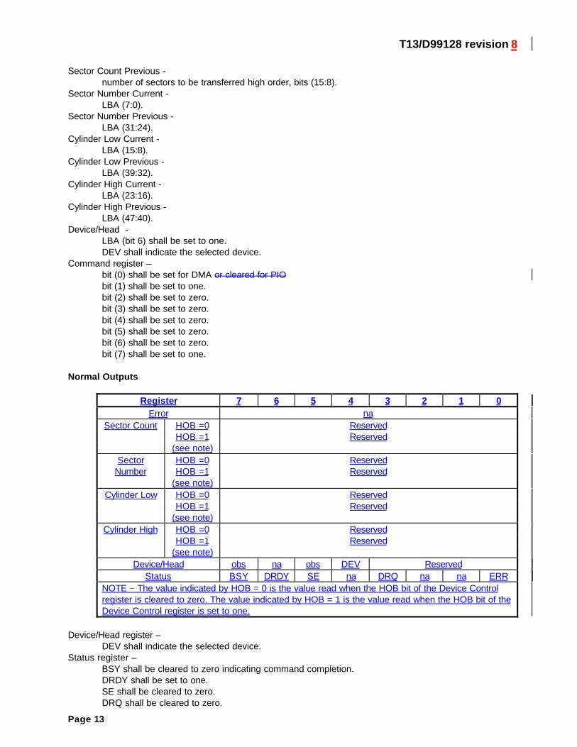
Sector Count Previous -number of sectors to be transferred high order, bits (15:8).
Sector Number Current -LBA (7:0).
Sector Number Previous -LBA (31:24).
Cylinder Low Current -LBA (15:8).
Cylinder Low Previous -LBA (39:32).
Cylinder High Current -LBA (23:16).
Cylinder High Previous -LBA (47:40).
Device/Head -LBA (bit 6) shall be set to one.DEV shall indicate the selected device.
Command register –bit (0) shall be set for DMA or cleared for PIObit (1) shall be set to one.bit (2) shall be set to zero.bit (3) shall be set to zero.bit (4) shall be set to zero.bit (5) shall be set to zero.bit (6) shall be set to zero.bit (7) shall be set to one.
Normal Outputs
Register 7 6 5 4 3 2 1 0Error na
Sector Count HOB =0 ReservedHOB =1 Reserved
(see note)Sector HOB =0 Reserved
Number HOB =1 Reserved(see note)
Cylinder Low HOB =0 ReservedHOB =1 Reserved
(see note)Cylinder High HOB =0 Reserved
HOB =1 Reserved(see note)
Device/Head obs na obs DEV ReservedStatus BSY DRDY SE na DRQ na na ERR
NOTE − The value indicated by HOB = 0 is the value read when the HOB bit of the Device Controlregister is cleared to zero. The value indicated by HOB = 1 is the value read when the HOB bit of theDevice Control register is set to one.
Device/Head register –DEV shall indicate the selected device.
Status register –BSY shall be cleared to zero indicating command completion.DRDY shall be set to one.SE shall be cleared to zero.DRQ shall be cleared to zero.
T13/D99128 revision 8
Page 14
ERR shall be cleared to zero.
Error Outputs
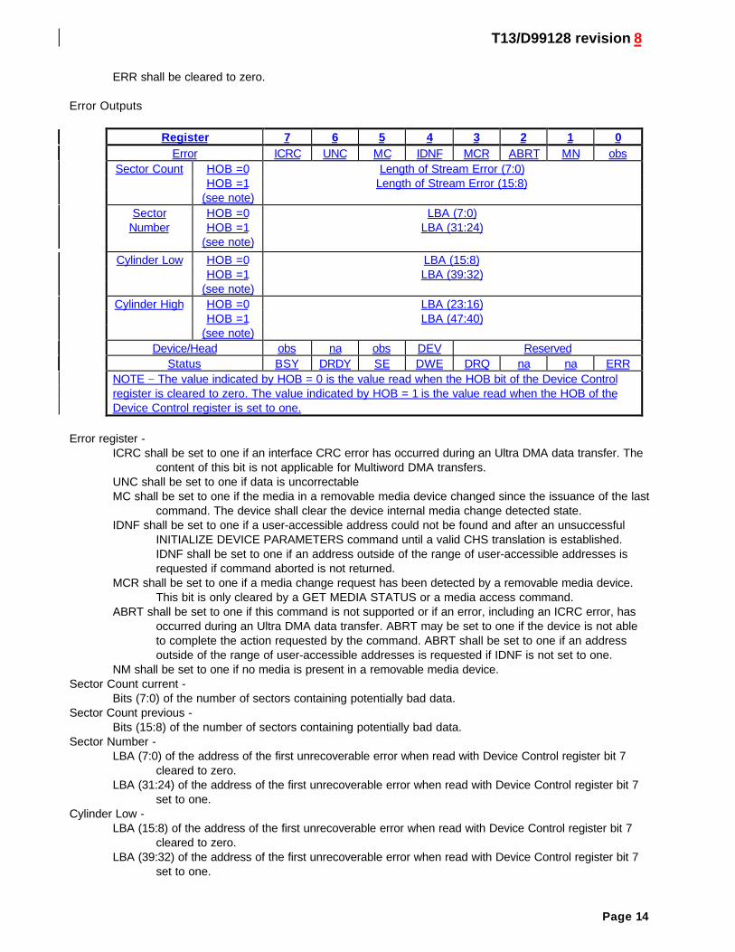
Register 7 6 5 4 3 2 1 0Error ICRC UNC MC IDNF MCR ABRT MN obs
Sector Count HOB =0 Length of Stream Error (7:0)HOB =1 Length of Stream Error (15:8)
(see note)Sector HOB =0 LBA (7:0)
Number HOB =1 LBA (31:24)(see note)
Cylinder Low HOB =0 LBA (15:8)HOB =1 LBA (39:32)
(see note)Cylinder High HOB =0 LBA (23:16)
HOB =1 LBA (47:40)(see note)
Device/Head obs na obs DEV ReservedStatus BSY DRDY SE DWE DRQ na na ERR
NOTE − The value indicated by HOB = 0 is the value read when the HOB bit of the Device Controlregister is cleared to zero. The value indicated by HOB = 1 is the value read when the HOB of theDevice Control register is set to one.
Error register -ICRC shall be set to one if an interface CRC error has occurred during an Ultra DMA data transfer. The
content of this bit is not applicable for Multiword DMA transfers.UNC shall be set to one if data is uncorrectableMC shall be set to one if the media in a removable media device changed since the issuance of the last
command. The device shall clear the device internal media change detected state.IDNF shall be set to one if a user-accessible address could not be found and after an unsuccessful
INITIALIZE DEVICE PARAMETERS command until a valid CHS translation is established.IDNF shall be set to one if an address outside of the range of user-accessible addresses isrequested if command aborted is not returned.
MCR shall be set to one if a media change request has been detected by a removable media device.This bit is only cleared by a GET MEDIA STATUS or a media access command.
ABRT shall be set to one if this command is not supported or if an error, including an ICRC error, hasoccurred during an Ultra DMA data transfer. ABRT may be set to one if the device is not ableto complete the action requested by the command. ABRT shall be set to one if an addressoutside of the range of user-accessible addresses is requested if IDNF is not set to one.
NM shall be set to one if no media is present in a removable media device.Sector Count current -
Bits (7:0) of the number of sectors containing potentially bad data.Sector Count previous -
Bits (15:8) of the number of sectors containing potentially bad data.Sector Number -
LBA (7:0) of the address of the first unrecoverable error when read with Device Control register bit 7cleared to zero.
LBA (31:24) of the address of the first unrecoverable error when read with Device Control register bit 7set to one.
Cylinder Low -LBA (15:8) of the address of the first unrecoverable error when read with Device Control register bit 7
cleared to zero.LBA (39:32) of the address of the first unrecoverable error when read with Device Control register bit 7
set to one.
T13/D99128 revision 8
Page 15
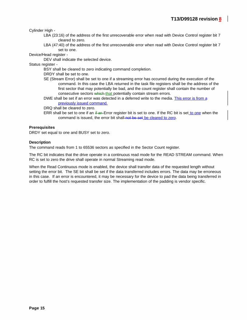
Cylinder High -LBA (23:16) of the address of the first unrecoverable error when read with Device Control register bit 7
cleared to zero.LBA (47:40) of the address of the first unrecoverable error when read with Device Control register bit 7
set to one.Device/Head register -
DEV shall indicate the selected device.Status register -
BSY shall be cleared to zero indicating command completion.DRDY shall be set to one.SE (Stream Error) shall be set to one if a streaming error has occurred during the execution of the
command. In this case the LBA returned in the task file registers shall be the address of thefirst sector that may potentially be bad, and the count register shall contain the number ofconsecutive sectors which that potentially contain stream errors.
DWE shall be set if an error was detected in a deferred write to the media. This error is from apreviously issued command.
DRQ shall be cleared to zero.ERR shall be set to one if an if an Error register bit is set to one. If the RC bit is set to one when the
command is issued, the error bit shall not be set be cleared to zero.
PrerequisitesDRDY set equal to one and BUSY set to zero.
DescriptionThe command reads from 1 to 65536 sectors as specified in the Sector Count register.
The RC bit indicates that the drive operate in a continuous read mode for the READ STREAM command. WhenRC is set to zero the drive shall operate in normal Streaming read mode.
When the Read Continuous mode is enabled, the device shall transfer data of the requested length withoutsetting the error bit. The SE bit shall be set if the data transferred includes errors. The data may be erroneousin this case. If an error is encountered, it may be necessary for the device to pad the data being transferred inorder to fulfill the host’s requested transfer size. The implementation of the padding is vendor specific.
T13/D99128 revision 8
Page 16
READ STREAM PIO
Command codeXXh
ProtocolPIO data-in (see 9.5)
Inputs
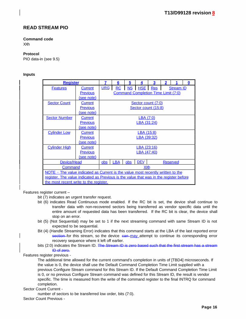
Register 7 6 5 4 3 2 1 0Features Current URG RC NS HSE Res Stream ID
Previous Command Completion Time Limit (7:0)(see note)
Sector Count Current Sector count (7:0)Previous Sector count (15:8)
(see note)Sector Number Current LBA (7:0)
Previous LBA (31:24)(see note)
Cylinder Low Current LBA (15:8)Previous LBA (39:32)
(see note)Cylinder High Current LBA (23:16)
Previous LBA (47:40)(see note)
Device/Head obs LBA obs DEV ReservedCommand XXh
NOTE − The value indicated as Current is the value most recently written to theregister. The value indicated as Previous is the value that was in the register beforethe most recent write to the register.
Features register current –bit (7) indicates an urgent transfer request.bit (6) indicates Read Continuous mode enabled. If the RC bit is set, the device shall continue to
transfer data with non-recovered sectors being transferred as vendor specific data until theentire amount of requested data has been transferred. If the RC bit is clear, the device shallstop on an error.
bit (5) (Not Sequential) may be set to 1 if the next streaming command with same Stream ID is notexpected to be sequential.
Bit (4) (Handle Streaming Error) indicates that this command starts at the LBA of the last reported errorsection for this stream, so the device can may attempt to continue its corresponding errorrecovery sequence where it left off earlier.
bits (2:0) indicates the Stream ID. The Stream ID is zero based such that the first stream has a streamID of zero.
Features register previous -The additional time allowed for the current command’s completion in units of [TBD4] microseconds. Ifthe value is 0, the device shall use the Default Command Completion Time Limit supplied with aprevious Configure Stream command for this Stream ID. If the Default Command Completion Time Limitis 0, or no previous Configure Stream command was defined for this Stream ID, the result is vendorspecific. The time is measured from the write of the command register to the final INTRQ for commandcompletion.
Sector Count Current -number of sectors to be transferred low order, bits (7:0).
Sector Count Previous -
T13/D99128 revision 8
Page 17
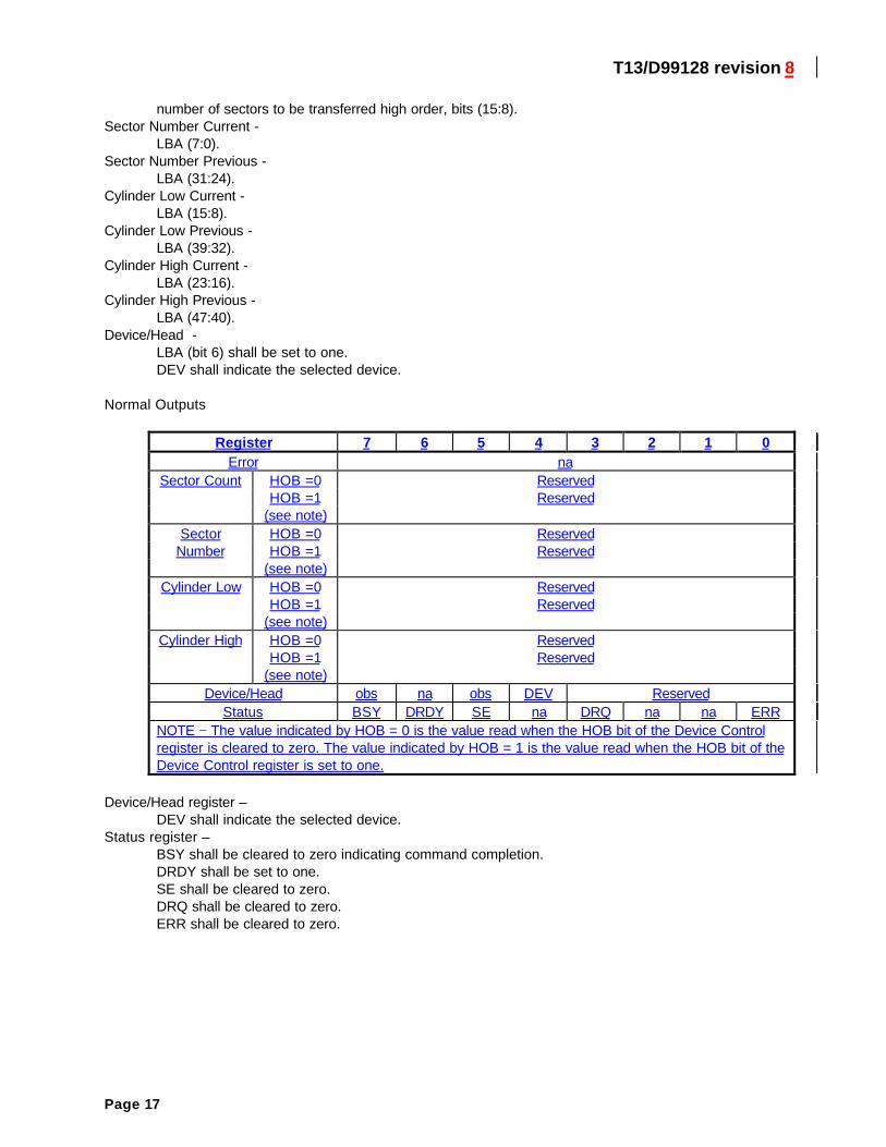
number of sectors to be transferred high order, bits (15:8).Sector Number Current -
LBA (7:0).Sector Number Previous -
LBA (31:24).Cylinder Low Current -
LBA (15:8).Cylinder Low Previous -
LBA (39:32).Cylinder High Current -
LBA (23:16).Cylinder High Previous -
LBA (47:40).Device/Head -
LBA (bit 6) shall be set to one.DEV shall indicate the selected device.
Normal Outputs
Register 7 6 5 4 3 2 1 0Error na
Sector Count HOB =0 ReservedHOB =1 Reserved
(see note)Sector HOB =0 Reserved
Number HOB =1 Reserved(see note)
Cylinder Low HOB =0 ReservedHOB =1 Reserved
(see note)Cylinder High HOB =0 Reserved
HOB =1 Reserved(see note)
Device/Head obs na obs DEV ReservedStatus BSY DRDY SE na DRQ na na ERR
NOTE − The value indicated by HOB = 0 is the value read when the HOB bit of the Device Controlregister is cleared to zero. The value indicated by HOB = 1 is the value read when the HOB bit of theDevice Control register is set to one.
Device/Head register –DEV shall indicate the selected device.
Status register –BSY shall be cleared to zero indicating command completion.DRDY shall be set to one.SE shall be cleared to zero.DRQ shall be cleared to zero.ERR shall be cleared to zero.
T13/D99128 revision 8
Page 18
Error Outputs
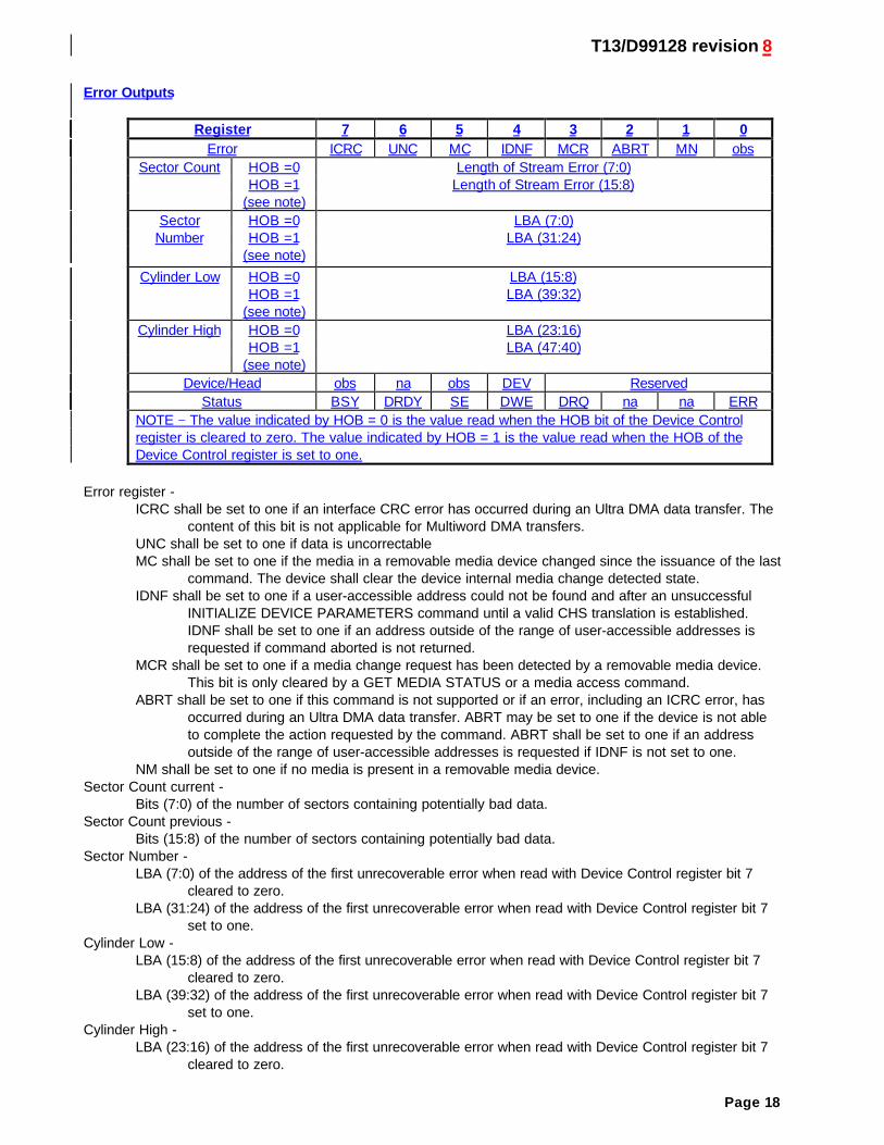
Register 7 6 5 4 3 2 1 0Error ICRC UNC MC IDNF MCR ABRT MN obs
Sector Count HOB =0 Length of Stream Error (7:0)HOB =1 Length of Stream Error (15:8)
(see note)Sector HOB =0 LBA (7:0)
Number HOB =1 LBA (31:24)(see note)
Cylinder Low HOB =0 LBA (15:8)HOB =1 LBA (39:32)
(see note)Cylinder High HOB =0 LBA (23:16)
HOB =1 LBA (47:40)(see note)
Device/Head obs na obs DEV ReservedStatus BSY DRDY SE DWE DRQ na na ERR
NOTE − The value indicated by HOB = 0 is the value read when the HOB bit of the Device Controlregister is cleared to zero. The value indicated by HOB = 1 is the value read when the HOB of theDevice Control register is set to one.
Error register -ICRC shall be set to one if an interface CRC error has occurred during an Ultra DMA data transfer. The
content of this bit is not applicable for Multiword DMA transfers.UNC shall be set to one if data is uncorrectableMC shall be set to one if the media in a removable media device changed since the issuance of the last
command. The device shall clear the device internal media change detected state.IDNF shall be set to one if a user-accessible address could not be found and after an unsuccessful
INITIALIZE DEVICE PARAMETERS command until a valid CHS translation is established.IDNF shall be set to one if an address outside of the range of user-accessible addresses isrequested if command aborted is not returned.
MCR shall be set to one if a media change request has been detected by a removable media device.This bit is only cleared by a GET MEDIA STATUS or a media access command.
ABRT shall be set to one if this command is not supported or if an error, including an ICRC error, hasoccurred during an Ultra DMA data transfer. ABRT may be set to one if the device is not ableto complete the action requested by the command. ABRT shall be set to one if an addressoutside of the range of user-accessible addresses is requested if IDNF is not set to one.
NM shall be set to one if no media is present in a removable media device.Sector Count current -
Bits (7:0) of the number of sectors containing potentially bad data.Sector Count previous -
Bits (15:8) of the number of sectors containing potentially bad data.Sector Number -
LBA (7:0) of the address of the first unrecoverable error when read with Device Control register bit 7cleared to zero.
LBA (31:24) of the address of the first unrecoverable error when read with Device Control register bit 7set to one.
Cylinder Low -LBA (15:8) of the address of the first unrecoverable error when read with Device Control register bit 7
cleared to zero.LBA (39:32) of the address of the first unrecoverable error when read with Device Control register bit 7
set to one.Cylinder High -
LBA (23:16) of the address of the first unrecoverable error when read with Device Control register bit 7cleared to zero.
T13/D99128 revision 8
Page 19
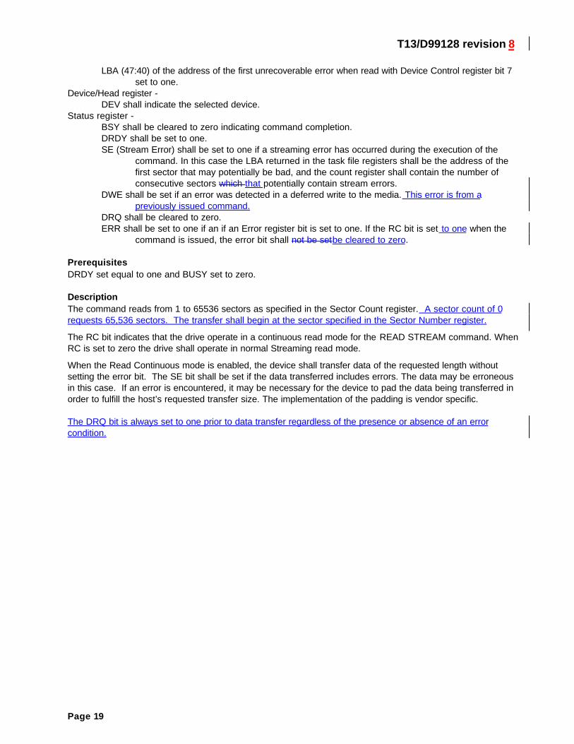
LBA (47:40) of the address of the first unrecoverable error when read with Device Control register bit 7set to one.
Device/Head register -DEV shall indicate the selected device.
Status register -BSY shall be cleared to zero indicating command completion.DRDY shall be set to one.SE (Stream Error) shall be set to one if a streaming error has occurred during the execution of the
command. In this case the LBA returned in the task file registers shall be the address of thefirst sector that may potentially be bad, and the count register shall contain the number ofconsecutive sectors which that potentially contain stream errors.
DWE shall be set if an error was detected in a deferred write to the media. This error is from apreviously issued command.
DRQ shall be cleared to zero.ERR shall be set to one if an if an Error register bit is set to one. If the RC bit is set to one when the
command is issued, the error bit shall not be setbe cleared to zero.
PrerequisitesDRDY set equal to one and BUSY set to zero.
DescriptionThe command reads from 1 to 65536 sectors as specified in the Sector Count register. A sector count of 0requests 65,536 sectors. The transfer shall begin at the sector specified in the Sector Number register.
The RC bit indicates that the drive operate in a continuous read mode for the READ STREAM command. WhenRC is set to zero the drive shall operate in normal Streaming read mode.
When the Read Continuous mode is enabled, the device shall transfer data of the requested length withoutsetting the error bit. The SE bit shall be set if the data transferred includes errors. The data may be erroneousin this case. If an error is encountered, it may be necessary for the device to pad the data being transferred inorder to fulfill the host’s requested transfer size. The implementation of the padding is vendor specific.
The DRQ bit is always set to one prior to data transfer regardless of the presence or absence of an errorcondition.
T13/D99128 revision 8
Page 20
WRITE STREAM DMA
Command codeXXh
ProtocolDMA (see 9.7)
Inputs
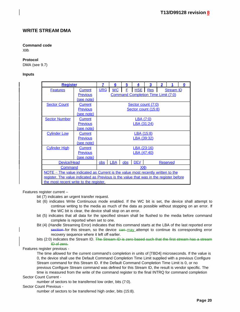
Register 7 6 5 4 3 2 1 0Features Current URG WC F HSE Res Stream ID
Previous Command Completion Time Limit (7:0)(see note)
Sector Count Current Sector count (7:0)Previous Sector count (15:8)
(see note)Sector Number Current LBA (7:0)
Previous LBA (31:24)(see note)
Cylinder Low Current LBA (15:8)Previous LBA (39:32)
(see note)Cylinder High Current LBA (23:16)
Previous LBA (47:40)(see note)
Device/Head obs LBA obs DEV ReservedCommand XXh
NOTE − The value indicated as Current is the value most recently written to theregister. The value indicated as Previous is the value that was in the register beforethe most recent write to the register.
Features register current –bit (7) indicates an urgent transfer request.bit (6) indicates Write Continuous mode enabled. If the WC bit is set, the device shall attempt to
continue writing to the media as much of the data as possible without stopping on an error. Ifthe WC bit is clear, the device shall stop on an error.
bit (5) indicates that all data for the specified stream shall be flushed to the media before commandcomplete is reported when set to one.
Bit (4) (Handle Streaming Error) indicates that this command starts at the LBA of the last reported errorsection for this stream, so the device can may attempt to continue its corresponding errorrecovery sequence where it left off earlier.
bits (2:0) indicates the Stream ID. The Stream ID is zero based such that the first stream has a streamID of zero.
Features register previous -The time allowed for the current command’s completion in units of [TBD4] microseconds. If the value is0, the device shall use the Default Command Completion Time Limit supplied with a previous ConfigureStream command for this Stream ID. If the Default Command Completion Time Limit is 0, or noprevious Configure Stream command was defined for this Stream ID, the result is vendor specific. Thetime is measured from the write of the command register to the final INTRQ for command completion
Sector Count Current -number of sectors to be transferred low order, bits (7:0).
Sector Count Previous -number of sectors to be transferred high order, bits (15:8).
T13/D99128 revision 8
Page 21
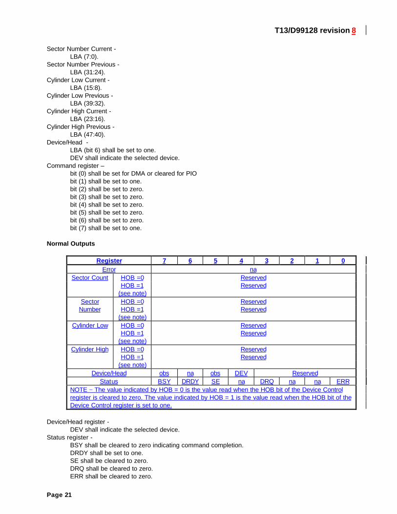
Sector Number Current -LBA (7:0).
Sector Number Previous -LBA (31:24).
Cylinder Low Current -LBA (15:8).
Cylinder Low Previous -LBA (39:32).
Cylinder High Current -LBA (23:16).
Cylinder High Previous -LBA (47:40).
Device/Head -LBA (bit 6) shall be set to one.DEV shall indicate the selected device.
Command register –bit (0) shall be set for DMA or cleared for PIObit (1) shall be set to one.bit (2) shall be set to zero.bit (3) shall be set to zero.bit (4) shall be set to zero.bit (5) shall be set to zero.bit (6) shall be set to zero.bit (7) shall be set to one.
Normal Outputs
Register 7 6 5 4 3 2 1 0Error na
Sector Count HOB =0 ReservedHOB =1 Reserved
(see note)Sector HOB =0 Reserved
Number HOB =1 Reserved(see note)
Cylinder Low HOB =0 ReservedHOB =1 Reserved
(see note)Cylinder High HOB =0 Reserved
HOB =1 Reserved(see note)
Device/Head obs na obs DEV ReservedStatus BSY DRDY SE na DRQ na na ERR
NOTE − The value indicated by HOB = 0 is the value read when the HOB bit of the Device Controlregister is cleared to zero. The value indicated by HOB = 1 is the value read when the HOB bit of theDevice Control register is set to one.
Device/Head register -DEV shall indicate the selected device.
Status register -BSY shall be cleared to zero indicating command completion.DRDY shall be set to one.SE shall be cleared to zero.DRQ shall be cleared to zero.ERR shall be cleared to zero.
T13/D99128 revision 8
Page 22
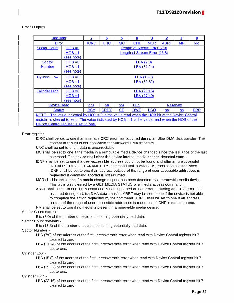
Error Outputs
Register 7 6 5 4 3 2 1 0Error ICRC UNC MC IDNF MCR ABRT MN obs
Sector Count HOB =0 Length of Stream Error (7:0)HOB =1 Length of Stream Error (15:8)
(see note)Sector HOB =0 LBA (7:0)
Number HOB =1 LBA (31:24)(see note)
Cylinder Low HOB =0 LBA (15:8)HOB =1 LBA (39:32)
(see note)Cylinder High HOB =0 LBA (23:16)
HOB =1 LBA (47:40)(see note)
Device/Head obs na obs DEV ReservedStatus BSY DRDY SE DWE DRQ na na ERR
NOTE − The value indicated by HOB = 0 is the value read when the HOB bit of the Device Controlregister is cleared to zero. The value indicated by HOB = 1 is the value read when the HOB of theDevice Control register is set to one.
Error register -ICRC shall be set to one if an interface CRC error has occurred during an Ultra DMA data transfer. The
content of this bit is not applicable for Multiword DMA transfers.UNC shall be set to one if data is uncorrectableMC shall be set to one if the media in a removable media device changed since the issuance of the last
command. The device shall clear the device internal media change detected state.IDNF shall be set to one if a user-accessible address could not be found and after an unsuccessful
INITIALIZE DEVICE PARAMETERS command until a valid CHS translation is established.IDNF shall be set to one if an address outside of the range of user-accessible addresses isrequested if command aborted is not returned.
MCR shall be set to one if a media change request has been detected by a removable media device.This bit is only cleared by a GET MEDIA STATUS or a media access command.
ABRT shall be set to one if this command is not supported or if an error, including an ICRC error, hasoccurred during an Ultra DMA data transfer. ABRT may be set to one if the device is not ableto complete the action requested by the command. ABRT shall be set to one if an addressoutside of the range of user-accessible addresses is requested if IDNF is not set to one.
NM shall be set to one if no media is present in a removable media device.Sector Count current -
Bits (7:0) of the number of sectors containing potentially bad data.Sector Count previous -
Bits (15:8) of the number of sectors containing potentially bad data.Sector Number -
LBA (7:0) of the address of the first unrecoverable error when read with Device Control register bit 7cleared to zero.
LBA (31:24) of the address of the first unrecoverable error when read with Device Control register bit 7set to one.
Cylinder Low -LBA (15:8) of the address of the first unrecoverable error when read with Device Control register bit 7
cleared to zero.LBA (39:32) of the address of the first unrecoverable error when read with Device Control register bit 7
set to one.Cylinder High -
LBA (23:16) of the address of the first unrecoverable error when read with Device Control register bit 7cleared to zero.
T13/D99128 revision 8
Page 23
LBA (47:40) of the address of the first unrecoverable error when read with Device Control register bit 7set to one.
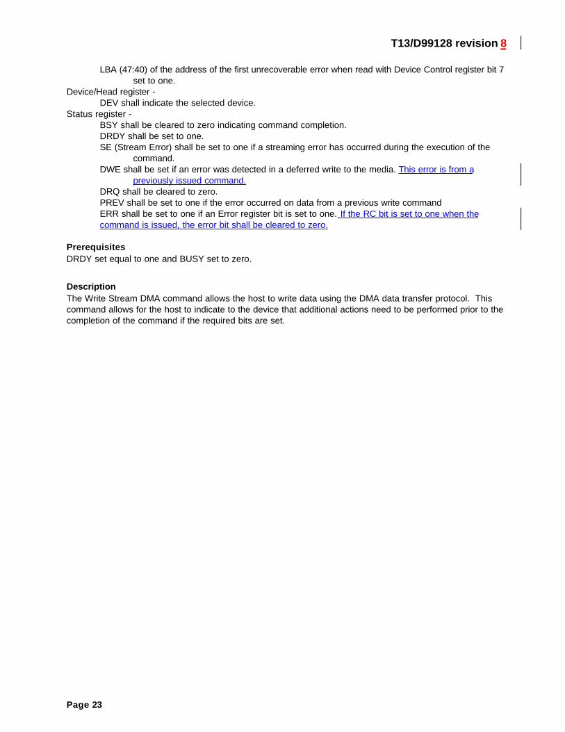
Device/Head register -DEV shall indicate the selected device.
Status register -BSY shall be cleared to zero indicating command completion.DRDY shall be set to one.SE (Stream Error) shall be set to one if a streaming error has occurred during the execution of the
command.DWE shall be set if an error was detected in a deferred write to the media. This error is from a
previously issued command.DRQ shall be cleared to zero.PREV shall be set to one if the error occurred on data from a previous write commandERR shall be set to one if an Error register bit is set to one. If the RC bit is set to one when thecommand is issued, the error bit shall be cleared to zero.
PrerequisitesDRDY set equal to one and BUSY set to zero.
DescriptionThe Write Stream DMA command allows the host to write data using the DMA data transfer protocol. Thiscommand allows for the host to indicate to the device that additional actions need to be performed prior to thecompletion of the command if the required bits are set.
T13/D99128 revision 8
Page 24
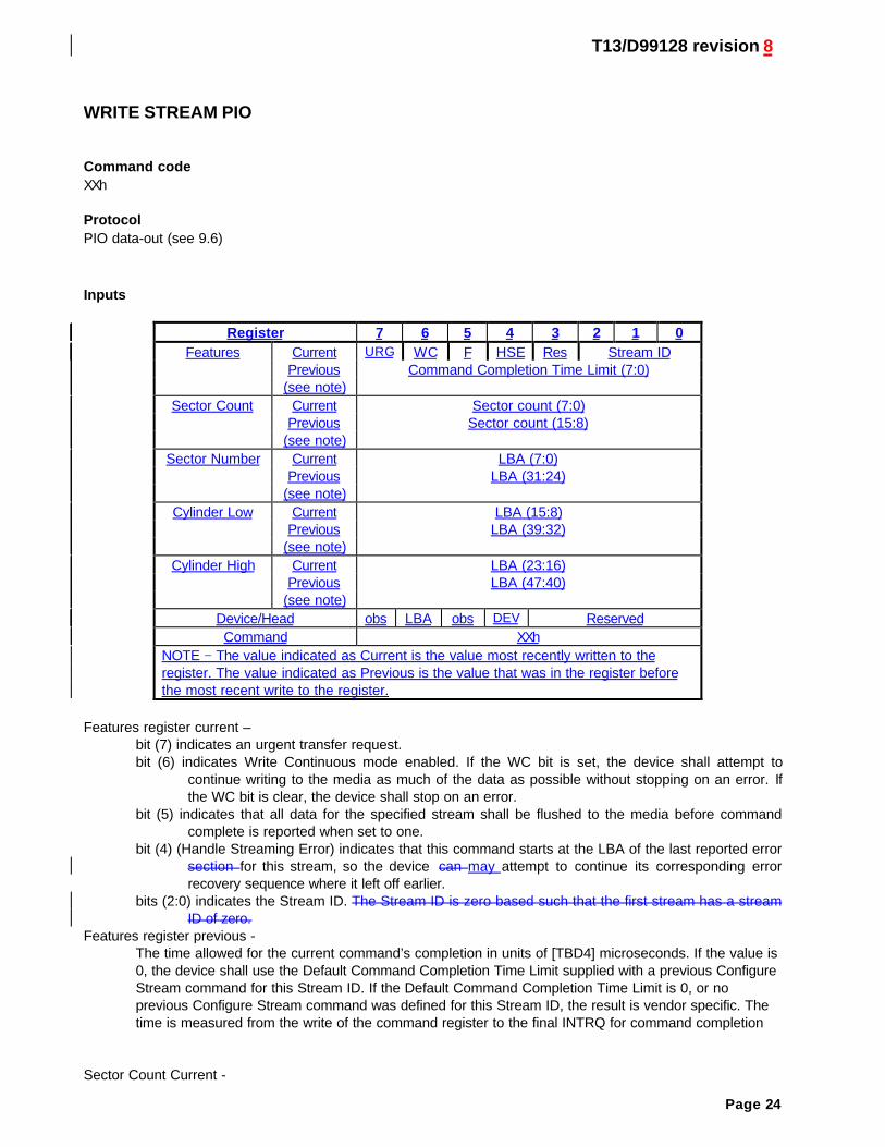
WRITE STREAM PIO
Command codeXXh
ProtocolPIO data-out (see 9.6)
Inputs
Register 7 6 5 4 3 2 1 0Features Current URG WC F HSE Res Stream ID
Previous Command Completion Time Limit (7:0)(see note)
Sector Count Current Sector count (7:0)Previous Sector count (15:8)
(see note)Sector Number Current LBA (7:0)
Previous LBA (31:24)(see note)
Cylinder Low Current LBA (15:8)Previous LBA (39:32)
(see note)Cylinder High Current LBA (23:16)
Previous LBA (47:40)(see note)
Device/Head obs LBA obs DEV ReservedCommand XXh
NOTE − The value indicated as Current is the value most recently written to theregister. The value indicated as Previous is the value that was in the register beforethe most recent write to the register.
Features register current –bit (7) indicates an urgent transfer request.bit (6) indicates Write Continuous mode enabled. If the WC bit is set, the device shall attempt to
continue writing to the media as much of the data as possible without stopping on an error. Ifthe WC bit is clear, the device shall stop on an error.
bit (5) indicates that all data for the specified stream shall be flushed to the media before commandcomplete is reported when set to one.
bit (4) (Handle Streaming Error) indicates that this command starts at the LBA of the last reported errorsection for this stream, so the device can may attempt to continue its corresponding errorrecovery sequence where it left off earlier.
bits (2:0) indicates the Stream ID. The Stream ID is zero based such that the first stream has a streamID of zero.
Features register previous -The time allowed for the current command’s completion in units of [TBD4] microseconds. If the value is0, the device shall use the Default Command Completion Time Limit supplied with a previous ConfigureStream command for this Stream ID. If the Default Command Completion Time Limit is 0, or noprevious Configure Stream command was defined for this Stream ID, the result is vendor specific. Thetime is measured from the write of the command register to the final INTRQ for command completion
Sector Count Current -
T13/D99128 revision 8
Page 25
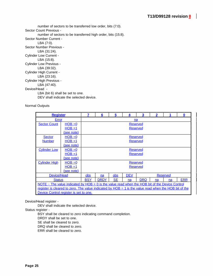
number of sectors to be transferred low order, bits (7:0).Sector Count Previous -
number of sectors to be transferred high order, bits (15:8).Sector Number Current -
LBA (7:0).Sector Number Previous -
LBA (31:24).Cylinder Low Current -
LBA (15:8).Cylinder Low Previous -
LBA (39:32).Cylinder High Current -
LBA (23:16).Cylinder High Previous -
LBA (47:40).Device/Head -
LBA (bit 6) shall be set to one.DEV shall indicate the selected device.
Normal Outputs
Register 7 6 5 4 3 2 1 0Error na
Sector Count HOB =0 ReservedHOB =1 Reserved
(see note)Sector HOB =0 Reserved
Number HOB =1 Reserved(see note)
Cylinder Low HOB =0 ReservedHOB =1 Reserved
(see note)Cylinder High HOB =0 Reserved
HOB =1 Reserved(see note)
Device/Head obs na obs DEV ReservedStatus BSY DRDY SE na DRQ na na ERR
NOTE − The value indicated by HOB = 0 is the value read when the HOB bit of the Device Controlregister is cleared to zero. The value indicated by HOB = 1 is the value read when the HOB bit of theDevice Control register is set to one.
Device/Head register -DEV shall indicate the selected device.
Status register -BSY shall be cleared to zero indicating command completion.DRDY shall be set to one.SE shall be cleared to zero.DRQ shall be cleared to zero.ERR shall be cleared to zero.
T13/D99128 revision 8
Page 26
Error Outputs
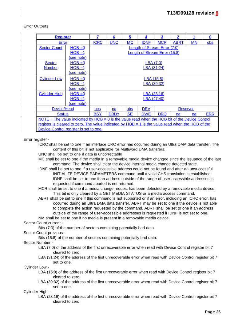
Register 7 6 5 4 3 2 1 0Error ICRC UNC MC IDNF MCR ABRT MN obs
Sector Count HOB =0 Length of Stream Error (7:0)HOB =1 Length of Stream Error (15:8)
(see note)Sector HOB =0 LBA (7:0)
Number HOB =1 LBA (31:24)(see note)
Cylinder Low HOB =0 LBA (15:8)HOB =1 LBA (39:32)
(see note)Cylinder High HOB =0 LBA (23:16)
HOB =1 LBA (47:40)(see note)
Device/Head obs na obs DEV ReservedStatus BSY DRDY SE DWE DRQ na na ERR
NOTE − The value indicated by HOB = 0 is the value read when the HOB bit of the Device Controlregister is cleared to zero. The value indicated by HOB = 1 is the value read when the HOB of theDevice Control register is set to one.
Error register -ICRC shall be set to one if an interface CRC error has occurred during an Ultra DMA data transfer. The
content of this bit is not applicable for Multiword DMA transfers.UNC shall be set to one if data is uncorrectableMC shall be set to one if the media in a removable media device changed since the issuance of the last
command. The device shall clear the device internal media change detected state.IDNF shall be set to one if a user-accessible address could not be found and after an unsuccessful
INITIALIZE DEVICE PARAMETERS command until a valid CHS translation is established.IDNF shall be set to one if an address outside of the range of user-accessible addresses isrequested if command aborted is not returned.
MCR shall be set to one if a media change request has been detected by a removable media device.This bit is only cleared by a GET MEDIA STATUS or a media access command.
ABRT shall be set to one if this command is not supported or if an error, including an ICRC error, hasoccurred during an Ultra DMA data transfer. ABRT may be set to one if the device is not ableto complete the action requested by the command. ABRT shall be set to one if an addressoutside of the range of user-accessible addresses is requested if IDNF is not set to one.
NM shall be set to one if no media is present in a removable media device.Sector Count current -
Bits (7:0) of the number of sectors containing potentially bad data.Sector Count previous -
Bits (15:8) of the number of sectors containing potentially bad data.Sector Number -
LBA (7:0) of the address of the first unrecoverable error when read with Device Control register bit 7cleared to zero.
LBA (31:24) of the address of the first unrecoverable error when read with Device Control register bit 7set to one.
Cylinder Low -LBA (15:8) of the address of the first unrecoverable error when read with Device Control register bit 7
cleared to zero.LBA (39:32) of the address of the first unrecoverable error when read with Device Control register bit 7
set to one.Cylinder High -
LBA (23:16) of the address of the first unrecoverable error when read with Device Control register bit 7cleared to zero.
T13/D99128 revision 8
Page 27
LBA (47:40) of the address of the first unrecoverable error when read with Device Control register bit 7set to one.
Device/Head register -DEV shall indicate the selected device.
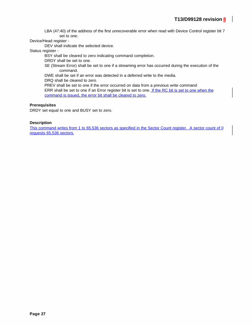
Status register -BSY shall be cleared to zero indicating command completion.DRDY shall be set to one.SE (Stream Error) shall be set to one if a streaming error has occurred during the execution of the
command.DWE shall be set if an error was detected in a deferred write to the media.DRQ shall be cleared to zero.PREV shall be set to one if the error occurred on data from a previous write commandERR shall be set to one if an Error register bit is set to one. If the RC bit is set to one when thecommand is issued, the error bit shall be cleared to zero.
PrerequisitesDRDY set equal to one and BUSY set to zero.
DescriptionThis command writes from 1 to 65,536 sectors as specified in the Sector Count register. A sector count of 0requests 65,536 sectors.
T13/D99128 revision 8
Page 28
Read Log Ext
Command codeTBD.
ProtocolPIO data-in (see 9.5).
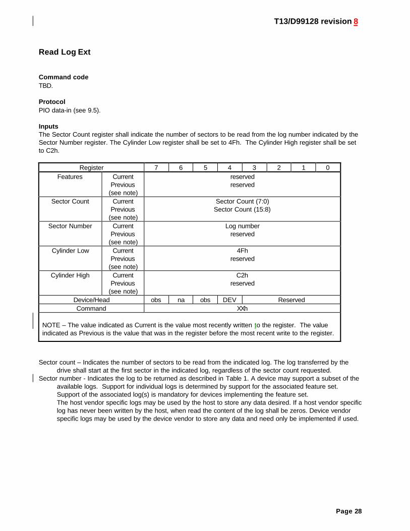
InputsThe Sector Count register shall indicate the number of sectors to be read from the log number indicated by theSector Number register. The Cylinder Low register shall be set to 4Fh. The Cylinder High register shall be setto C2h.
Register 7 6 5 4 3 2 1 0Features Current
Previous(see note)
reservedreserved
Sector Count CurrentPrevious
(see note)
Sector Count (7:0)Sector Count (15:8)
Sector Number CurrentPrevious
(see note)
Log numberreserved
Cylinder Low CurrentPrevious
(see note)
4Fhreserved
Cylinder High CurrentPrevious
(see note)
C2hreserved
Device/Head obs na obs DEV ReservedCommand XXh
NOTE – The value indicated as Current is the value most recently written to the register. The valueindicated as Previous is the value that was in the register before the most recent write to the register.
Sector count – Indicates the number of sectors to be read from the indicated log. The log transferred by thedrive shall start at the first sector in the indicated log, regardless of the sector count requested.
Sector number - Indicates the log to be returned as described in Table 1. A device may support a subset of theavailable logs. Support for individual logs is determined by support for the associated feature set.Support of the associated log(s) is mandatory for devices implementing the feature set.The host vendor specific logs may be used by the host to store any data desired. If a host vendor specificlog has never been written by the host, when read the content of the log shall be zeros. Device vendorspecific logs may be used by the device vendor to store any data and need only be implemented if used.
T13/D99128 revision 8
Page 29
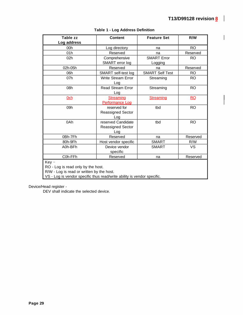
Table 1 - Log Address Definition
Table zzLog address
Content Feature Set R/W
00h Log directory na RO01h Reserved na Reserved02h Comprehensive
SMART error logSMART Error
LoggingRO
02h-05h Reserved na Reserved06h SMART self-test log SMART Self Test RO07h Write Stream Error
LogStreaming RO
08h Read Stream ErrorLog
Streaming RO
0xh StreamingPerformance Log
Streaming RO
09h reserved forReassigned Sector
Log
tbd RO
0Ah reserved CandidateReassigned Sector
Log
tbd RO
0Bh-7Fh Reserved na Reserved80h-9Fh Host vendor specific SMART R/WA0h-BFh Device vendor
specificSMART VS
C0h-FFh Reserved na ReservedKey −RO - Log is read only by the host.R/W - Log is read or written by the host.VS - Log is vendor specific thus read/write ability is vendor specific.
Device/Head register -DEV shall indicate the selected device.
T13/D99128 revision 8
Page 30
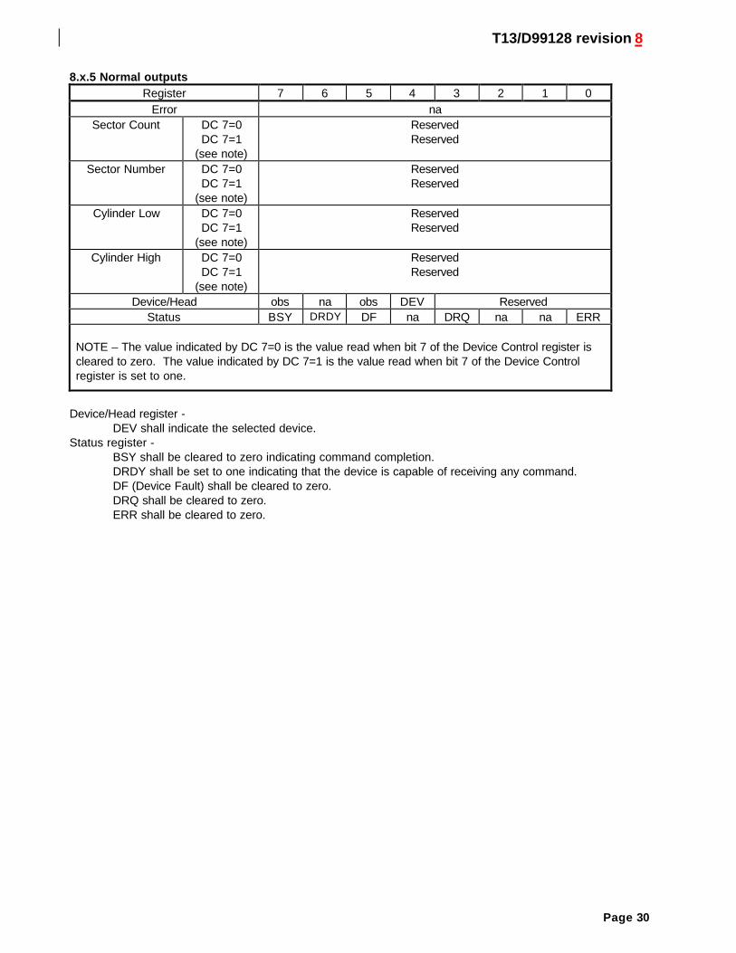
8.x.5 Normal outputsRegister 7 6 5 4 3 2 1 0
Error naSector Count DC 7=0
DC 7=1(see note)
ReservedReserved
Sector Number DC 7=0DC 7=1
(see note)
ReservedReserved
Cylinder Low DC 7=0DC 7=1
(see note)
ReservedReserved
Cylinder High DC 7=0DC 7=1
(see note)
ReservedReserved
Device/Head obs na obs DEV ReservedStatus BSY DRDY DF na DRQ na na ERR
NOTE – The value indicated by DC 7=0 is the value read when bit 7 of the Device Control register iscleared to zero. The value indicated by DC 7=1 is the value read when bit 7 of the Device Controlregister is set to one.
Device/Head register -DEV shall indicate the selected device.
Status register -BSY shall be cleared to zero indicating command completion.DRDY shall be set to one indicating that the device is capable of receiving any command.DF (Device Fault) shall be cleared to zero.DRQ shall be cleared to zero.ERR shall be cleared to zero.
T13/D99128 revision 8
Page 31
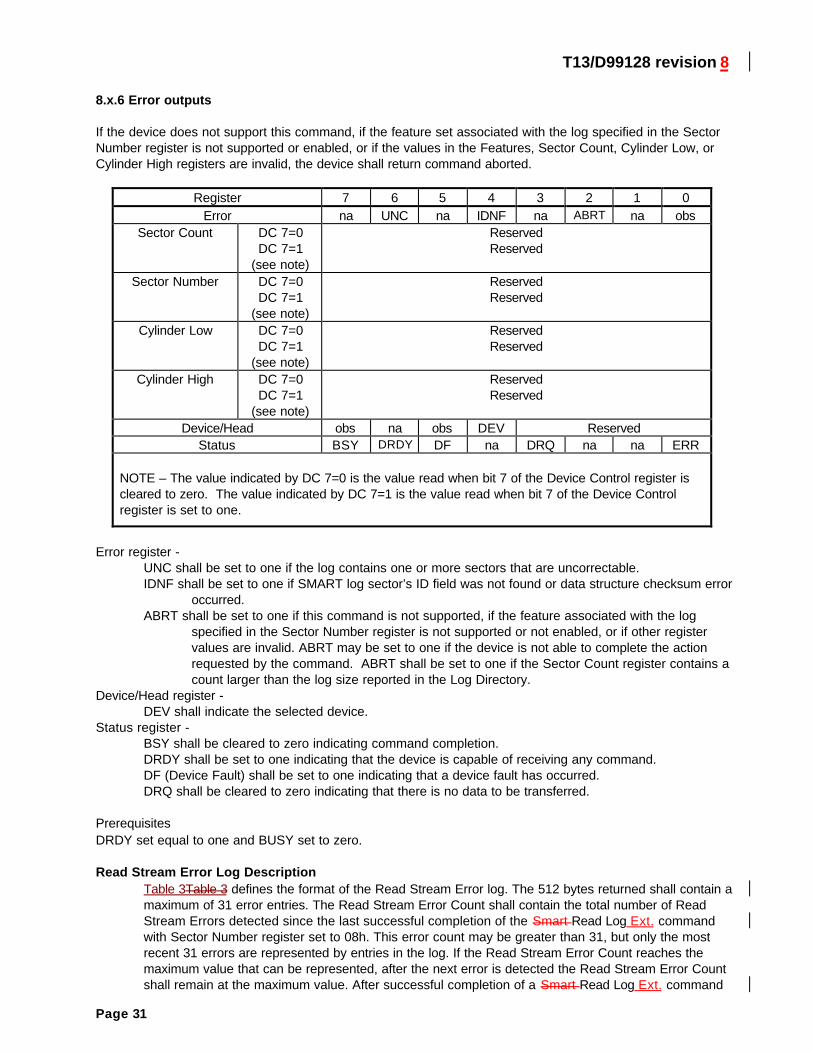
8.x.6 Error outputs
If the device does not support this command, if the feature set associated with the log specified in the SectorNumber register is not supported or enabled, or if the values in the Features, Sector Count, Cylinder Low, orCylinder High registers are invalid, the device shall return command aborted.
Register 7 6 5 4 3 2 1 0Error na UNC na IDNF na ABRT na obs
Sector Count DC 7=0DC 7=1
(see note)
ReservedReserved
Sector Number DC 7=0DC 7=1
(see note)
ReservedReserved
Cylinder Low DC 7=0DC 7=1
(see note)
ReservedReserved
Cylinder High DC 7=0DC 7=1
(see note)
ReservedReserved
Device/Head obs na obs DEV ReservedStatus BSY DRDY DF na DRQ na na ERR
NOTE – The value indicated by DC 7=0 is the value read when bit 7 of the Device Control register iscleared to zero. The value indicated by DC 7=1 is the value read when bit 7 of the Device Controlregister is set to one.
Error register -UNC shall be set to one if the log contains one or more sectors that are uncorrectable.IDNF shall be set to one if SMART log sector’s ID field was not found or data structure checksum error
occurred.ABRT shall be set to one if this command is not supported, if the feature associated with the log
specified in the Sector Number register is not supported or not enabled, or if other registervalues are invalid. ABRT may be set to one if the device is not able to complete the actionrequested by the command. ABRT shall be set to one if the Sector Count register contains acount larger than the log size reported in the Log Directory.
Device/Head register -DEV shall indicate the selected device.
Status register -BSY shall be cleared to zero indicating command completion.DRDY shall be set to one indicating that the device is capable of receiving any command.DF (Device Fault) shall be set to one indicating that a device fault has occurred.DRQ shall be cleared to zero indicating that there is no data to be transferred.
PrerequisitesDRDY set equal to one and BUSY set to zero.
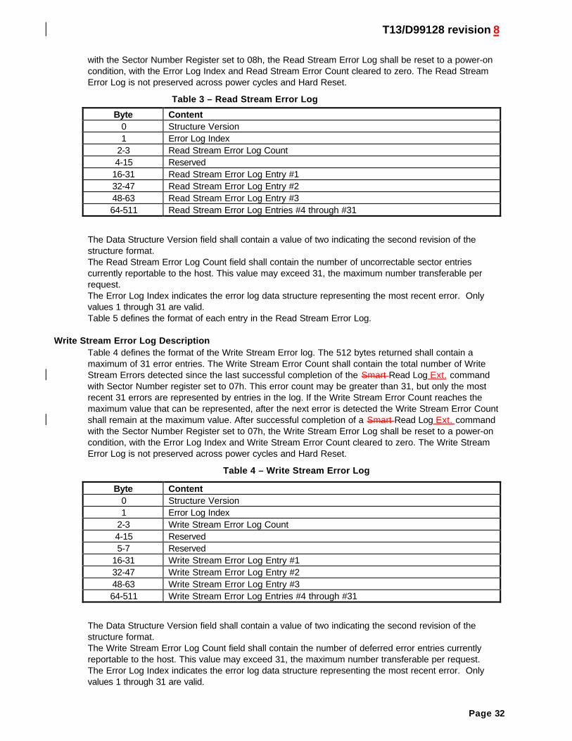
Read Stream Error Log DescriptionTable 3Table 3 defines the format of the Read Stream Error log. The 512 bytes returned shall contain amaximum of 31 error entries. The Read Stream Error Count shall contain the total number of ReadStream Errors detected since the last successful completion of the Smart Read Log Ext. commandwith Sector Number register set to 08h. This error count may be greater than 31, but only the mostrecent 31 errors are represented by entries in the log. If the Read Stream Error Count reaches themaximum value that can be represented, after the next error is detected the Read Stream Error Countshall remain at the maximum value. After successful completion of a Smart Read Log Ext. command
T13/D99128 revision 8
Page 32
with the Sector Number Register set to 08h, the Read Stream Error Log shall be reset to a power-oncondition, with the Error Log Index and Read Stream Error Count cleared to zero. The Read StreamError Log is not preserved across power cycles and Hard Reset.
Table 3 – Read Stream Error Log
Byte Content0 Structure Version1 Error Log Index
2-3 Read Stream Error Log Count4-15 Reserved
16-31 Read Stream Error Log Entry #132-47 Read Stream Error Log Entry #248-63 Read Stream Error Log Entry #364-511 Read Stream Error Log Entries #4 through #31
The Data Structure Version field shall contain a value of two indicating the second revision of thestructure format.The Read Stream Error Log Count field shall contain the number of uncorrectable sector entriescurrently reportable to the host. This value may exceed 31, the maximum number transferable perrequest.The Error Log Index indicates the error log data structure representing the most recent error. Onlyvalues 1 through 31 are valid.Table 5 defines the format of each entry in the Read Stream Error Log.
Write Stream Error Log DescriptionTable 4 defines the format of the Write Stream Error log. The 512 bytes returned shall contain amaximum of 31 error entries. The Write Stream Error Count shall contain the total number of WriteStream Errors detected since the last successful completion of the Smart Read Log Ext. commandwith Sector Number register set to 07h. This error count may be greater than 31, but only the mostrecent 31 errors are represented by entries in the log. If the Write Stream Error Count reaches themaximum value that can be represented, after the next error is detected the Write Stream Error Countshall remain at the maximum value. After successful completion of a Smart Read Log Ext. commandwith the Sector Number Register set to 07h, the Write Stream Error Log shall be reset to a power-oncondition, with the Error Log Index and Write Stream Error Count cleared to zero. The Write StreamError Log is not preserved across power cycles and Hard Reset.
Table 4 – Write Stream Error Log
Byte Content0 Structure Version1 Error Log Index
2-3 Write Stream Error Log Count4-15 Reserved5-7 Reserved
16-31 Write Stream Error Log Entry #132-47 Write Stream Error Log Entry #248-63 Write Stream Error Log Entry #364-511 Write Stream Error Log Entries #4 through #31
The Data Structure Version field shall contain a value of two indicating the second revision of thestructure format.The Write Stream Error Log Count field shall contain the number of deferred error entries currentlyreportable to the host. This value may exceed 31, the maximum number transferable per request.The Error Log Index indicates the error log data structure representing the most recent error. Onlyvalues 1 through 31 are valid.
T13/D99128 revision 8
Page 33
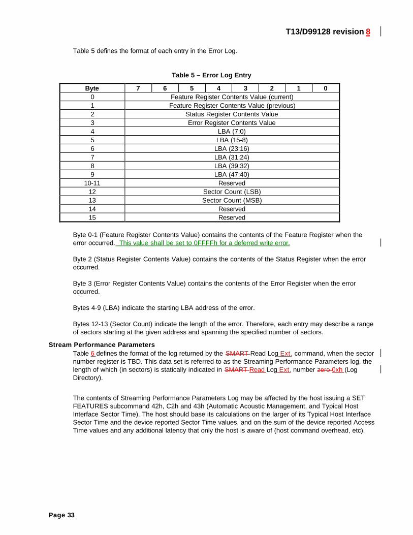
Table 5 defines the format of each entry in the Error Log.
Table 5 – Error Log Entry
Byte 7 6 5 4 3 2 1 00 Feature Register Contents Value (current)1 Feature Register Contents Value (previous)2 Status Register Contents Value3 Error Register Contents Value4 LBA (7:0)5 LBA (15-8)6 LBA (23:16)7 LBA (31:24)8 LBA (39:32)9 LBA (47:40)
10-11 Reserved12 Sector Count (LSB)13 Sector Count (MSB)14 Reserved15 Reserved
Byte 0-1 (Feature Register Contents Value) contains the contents of the Feature Register when theerror occurred. This value shall be set to 0FFFFh for a deferred write error.
Byte 2 (Status Register Contents Value) contains the contents of the Status Register when the erroroccurred.
Byte 3 (Error Register Contents Value) contains the contents of the Error Register when the erroroccurred.
Bytes 4-9 (LBA) indicate the starting LBA address of the error.
Bytes 12-13 (Sector Count) indicate the length of the error. Therefore, each entry may describe a rangeof sectors starting at the given address and spanning the specified number of sectors.
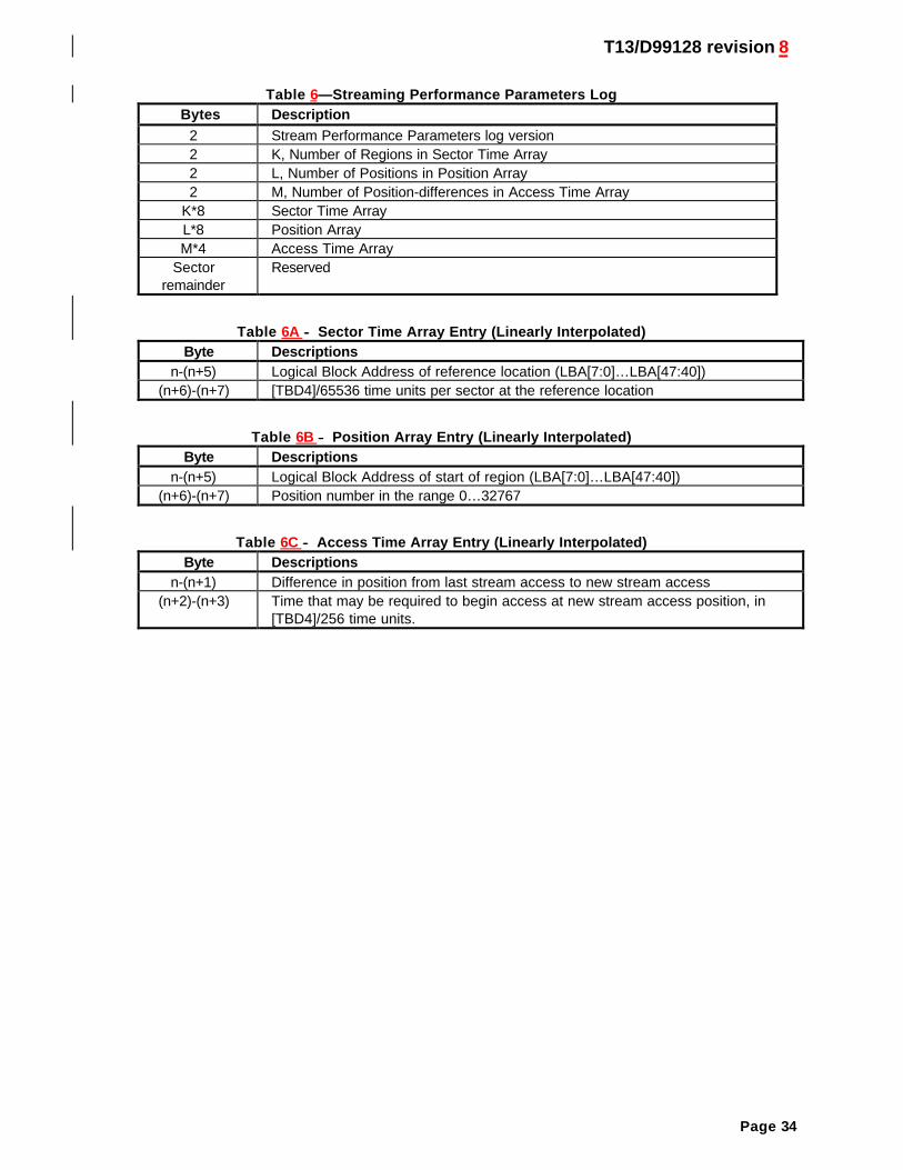
Stream Performance ParametersTable 6 defines the format of the log returned by the SMART Read Log Ext. command, when the sectornumber register is TBD. This data set is referred to as the Streaming Performance Parameters log, thelength of which (in sectors) is statically indicated in SMART Read Log Ext. number zero 0xh (LogDirectory).
The contents of Streaming Performance Parameters Log may be affected by the host issuing a SETFEATURES subcommand 42h, C2h and 43h (Automatic Acoustic Management, and Typical HostInterface Sector Time). The host should base its calculations on the larger of its Typical Host InterfaceSector Time and the device reported Sector Time values, and on the sum of the device reported AccessTime values and any additional latency that only the host is aware of (host command overhead, etc).
T13/D99128 revision 8
Page 34
Table 6—Streaming Performance Parameters LogBytes Description
2 Stream Performance Parameters log version2 K, Number of Regions in Sector Time Array2 L, Number of Positions in Position Array2 M, Number of Position-differences in Access Time Array
K*8 Sector Time ArrayL*8 Position ArrayM*4 Access Time Array
Sectorremainder
Reserved
Table 6A −− Sector Time Array Entry (Linearly Interpolated)Byte Descriptions
n-(n+5) Logical Block Address of reference location (LBA[7:0]…LBA[47:40])(n+6)-(n+7) [TBD4]/65536 time units per sector at the reference location
Table 6B −− Position Array Entry (Linearly Interpolated)Byte Descriptions
n-(n+5) Logical Block Address of start of region (LBA[7:0]…LBA[47:40])(n+6)-(n+7) Position number in the range 0…32767
Table 6C −− Access Time Array Entry (Linearly Interpolated)Byte Descriptions
n-(n+1) Difference in position from last stream access to new stream access(n+2)-(n+3) Time that may be required to begin access at new stream access position, in
[TBD4]/256 time units.