Embed Size (px)
Citation preview
PROPOSAL FOR A STANDARDIZED TEST ARTIFACT FOR ADDITIVE MANUFACTURING MACHINES AND PROCESSES
Shawn Moylan, John Slotwinski, April Cooke, Kevin Jurrens, and M. Alkan Donmez
Engineering Laboratory, National Institute of Standards and Technology1
, Gaithersburg, MD 20899
Abstract Historically, standardized test parts are used to quantitatively evaluate the performance of a
machine or process. While several different additive manufacturing (AM) test parts have been developed in the past, there are no current standard test parts. This paper reviews existing AM test parts, discusses the purposes of the studies, and describes important features and characteristics found in these test parts. A new test part intended for standardization is proposed. This part incorporates the most useful features seen in previous test parts. These features are designed to highlight process capabilities and test machine accuracy. The design has been validated through builds by several AM processes.
1. Introduction
Additive manufacturing (AM)—also known as additive fabrication, additive processes,
additive techniques, additive layer manufacturing, layered manufacturing, and freeform fabrication—is defined as the process of joining materials to make objects from three-dimensional (3D) model data, usually layer upon layer, as opposed to subtractive manufacturing methodologies such as machining [1]. Using AM to make functional components has grown from the initial applications in rapid prototyping (RP), where the resulting part was used for form, fit, and/or functional testing. Additive manufacturing processes demonstrate significant potential for a revolutionary, rapid, art-to-part capability for making high-value, complex, and individually-customized parts. Additive processes promise the ability to manufacture parts that are difficult or impossible to make with conventional manufacturing techniques, e.g., parts with complex geometries, engineered porosity, or lattice structures. However, widespread adoption of additive processes is currently hindered by deficiencies in part accuracy, surface finish, materials and material properties, process speed, and standards.
The goal of the AM projects at the National Institute of Standards and Technology (NIST)2
1 Official contribution of the National Institute of Standards and Technology (NIST); not subject to copyright in the United States. The full descriptions of the procedures used in this paper require the identification of certain commercial products. The inclusion of such information should in no way be construed as indicating that such products are endorsed by NIST or are recommended by NIST or that they are necessarily the best materials, instruments, software or suppliers for the purposes described.
is to facilitate the widespread adoption of metal-based additive processes. This will be accomplished through a better science-based understanding of the process via improved measurements, test methods, and standards. The work focuses on metal-based processes because parts produced by these processes are likely to be used as functional components, have a higher inherent value than other materials, and require further improvements (compared to, for example,
2 http://www.nist.gov/el/isd/sbm/matstandaddmanu.cfm; http://www.nist.gov/el/isd/sbm/fundmeasursci.cfm
polymer-based AM processes) before widespread acceptance can be achieved. The NIST projects address measurements and standards for the characterization of AM processes and equipment, as well as characterization of the materials used in and resulting from AM processes. NIST’s expertise and established presence in metrology methods and standards for traditional metal removal processes offer a unique perspective to the AM community.
In manufacturing metrology, two primary methodologies are used to evaluate the
performance of a machine and/or a process: (1) through a series of direct measurements of machine and process characteristics, and (2) through measurements of manufactured test artifacts. The former requires positioning and/or control of individual machine components (e.g., an axis) and measuring instruments mounted in and around the machine’s work volume to measure relative position, orientation, and velocities of these machine components. This is often difficult or impossible with AM machines, either because the moving components are not accessible to the end user or safety controls for potential hazards (e.g., high power lasers) prevent the user from operating the machine with the measuring instruments in the way. As such, test artifacts play a larger role in diagnosing and characterizing AM machines and processes, and clever design of test artifacts can allow performance assessment of individual machine components.
Manufacturing a test artifact enables a composite test since most errors present in the
machine and the process contribute to errors in the part. The disadvantage of composite tests is that linking specific part errors to specific machine or process error sources is often difficult. However, the advantages of test artifacts are that producing parts is directly aligned with the actual purpose of the machine and specialized measuring equipment is typically not necessary since the required equipment is already commonly available in discrete part manufacturing environments.
A standardized test part can be used to quantitatively evaluate the performance of a machine
or process. The clear benefit of a standardized part is that different machines or processes that produce the same standardized part can be easily compared. Additionally, if designed properly, the standard test part can test the limitations of the machine or process and be used to identify areas for improvement. The standardized test part can serve as a method for performance verification between users and vendors, as well as provide a platform for vendors to demonstrate improvements in their machines.
This document reviews existing test artifacts used to characterize AM processes that are
reported in the literature, discusses important criteria for designing a test artifact for AM, and proposes a test artifact for AM intended for standardization. Several aspects of test artifacts and their use for performance characterization are discussed, including the purposes of prior studies, important features found in various test artifacts, and characteristics that are desirable in test artifacts.
2. Prior Work
Based on a substantial review of the available literature, the following sub-sections briefly
discuss many of the test artifacts used to characterize different aspects of the performance of
additive processes. The resulting works are described in four categories: test artifacts for comparing processes for decision making, test artifacts for evaluating individual processes, test artifacts for evaluating metal-based processes, and test artifacts for other uses. This discussion is by no means exhaustive, nor is it unique.
2.1 Test Artifacts for Comparing Processes for Decision Making
Additive manufacturing gained prominence in the late 1980s and early 1990s as layered manufacturing or rapid prototyping (RP). Over this time period, various additive processes were developed and marketed by different vendors. Stereolithography (SLA) was the first additive RP process, followed closely by fused deposition modeling (FDM), laminated object manufacturing (LOM), and selective laser sintering (SLS). As AM matured, many more processes, such as three-dimensional printing (3D printing) and polyjet, entered the market. Users wanting to benefit from the advantages of RP had to choose which of the processes best fit their application.
Many researchers proposed the use of test artifacts, often called benchmarking parts, to
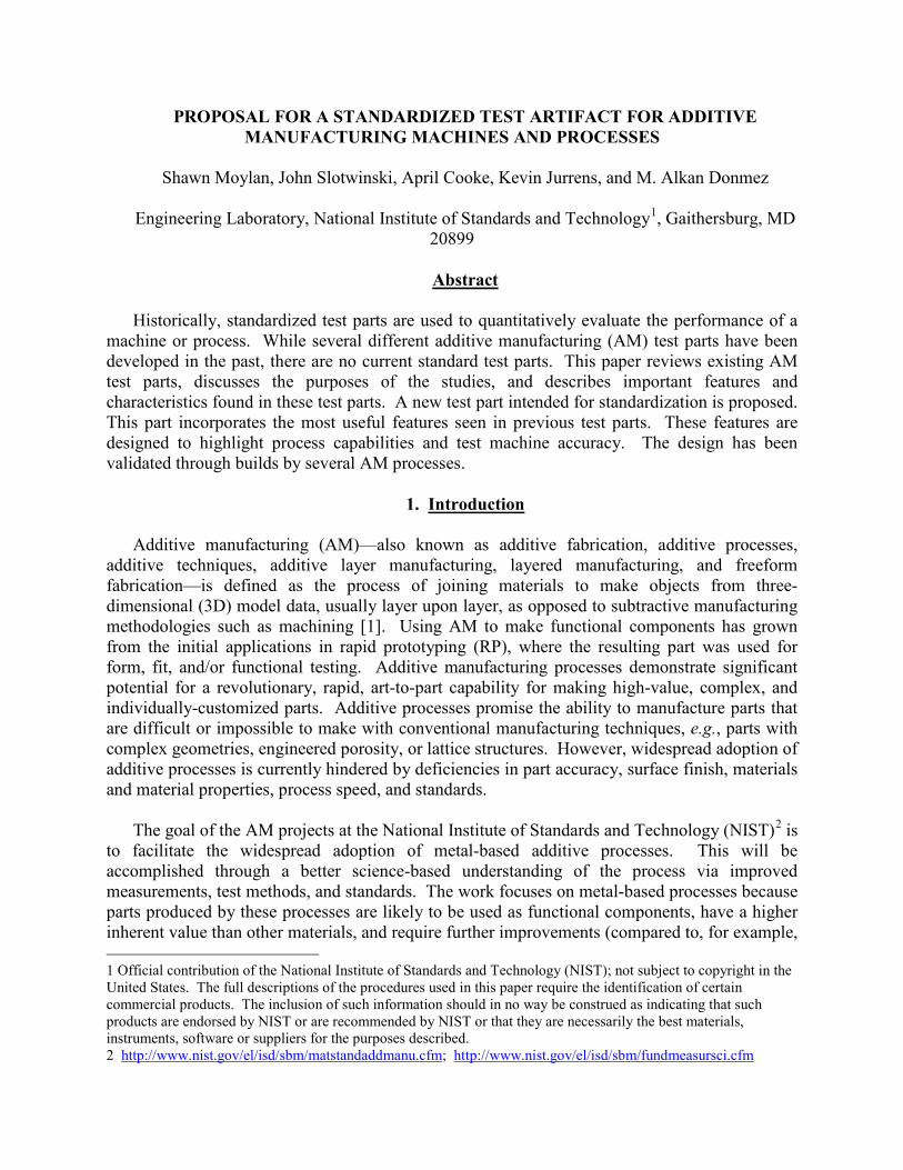
quantitatively compare the capabilities of the various processes [2-16]. Kruth was the first to mention a test artifact for comparing AM processes, citing a study done by two Dutch companies using a U-shaped artifact with various geometric features such as circular holes (in various orientations), circular bosses, square holes, and angled surfaces [2]. Other researchers built upon these results, adding more or different features, including overhangs and freeform features, to demonstrate some of the advantages of additive processes (see Figure 1) [4, 12]. Still more researchers followed, investigating the surface roughness of test parts in addition to geometric accuracy as a means to compare AM processes [6, 7]. As additional AM processes gained prominence, researchers added these to the comparative studies. For example, Byun added 3D printing [9] and Kim added polyjet [14]. Ultimately, specific AM processes gained sufficient capability and acceptance to support multiple machine platforms and manufacturers, leading to comparative studies of systems within a process family, e.g., seven types of 3D printing machines produced by six different manufacturers [10, 11].
Figure 1. Solid model of the test artifact used by Mahesh [12].
2.2 Test Artifacts for Evaluating Individual Processes Artifacts are also used to evaluate individual processes, either when a new process or
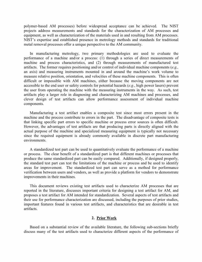
material emerges in the market [17-24] or when process optimization is the goal of the study [25, 26]. The so-called “user part” is one of the first test artifacts designed to quantitatively assess the
accuracy of SLA systems (see Figure 2) [17]. This part was designed in 1990 by an SLA user group and focuses on assessing the machine accuracy in the x-y plane. This same part or slight variations of it have been used by many other studies to characterize other additive processes, including evaluation of SLS for indirect manufacturing of metallic components (i.e., using SLS to create an intermediate, “green” part that must undergo subsequent post processing to become fully dense) [19]. Additionally, when new material options are introduced into an established process, it is important to quantify the accuracy of parts made with this new material [22, 24].
Figure 2. Solid model of the “user part.”
Development of new materials led to the first test artifacts dedicated to process improvement
and optimization. During SLA’s first years, newer, stronger materials were being quickly developed and introduced into user systems. The “windowpane” and “Christmas tree” test artifacts were used at this time to quantify the effects of changing various process settings, leading to iterative optimization of process design [25].
Examining the literature for use of test artifacts to evaluate individual processes may lead to
the incorrect conclusion that using a test artifact to optimize process parameters is uncommon. In reality, most AM system manufacturers and users working on process development typically have their own internal test artifacts for this purpose, though their designs remain largely proprietary.
2.3 Test Artifacts for Evaluating Metal-Based Processes
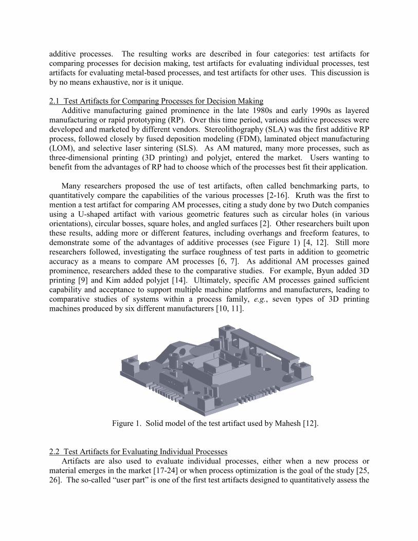
In recent years, the capabilities of metal-based AM processes have grown tremendously and these systems have emerged as viable methods for the direct manufacturing of metallic parts (i.e., using an energy source to melt and bond metal raw materials, creating a fully-dense part without the need for substantial post-processing). Numerous studies have concentrated on benchmark parts to evaluate metal-based AM processes [27-34]. The various processes that have been studied include selective laser sintering (SLS), selective laser melting (SLM), direct metal laser sintering (DMLS), electron beam melting (EBM), and micro-welding technologies. Kruth took a traditional approach by creating a test artifact with characteristic features to determine and analyze geometric errors and surface roughness (see Figure 3) [27]. Additionally, this artifact
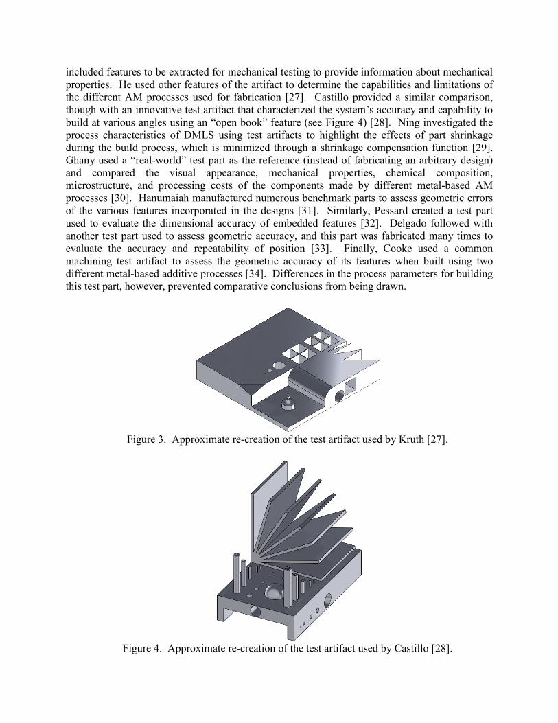
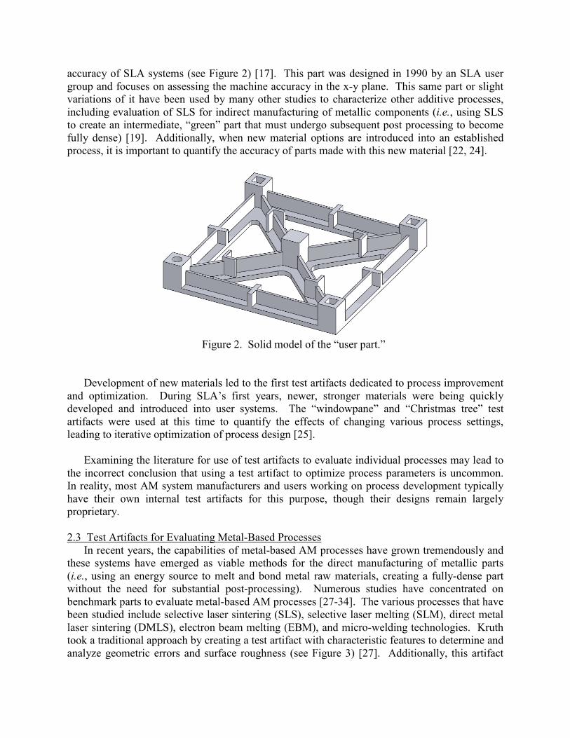
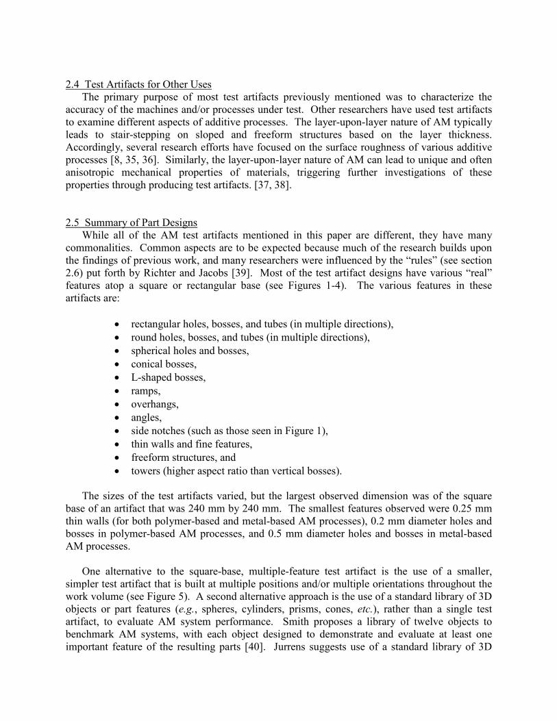
included features to be extracted for mechanical testing to provide information about mechanical properties. He used other features of the artifact to determine the capabilities and limitations of the different AM processes used for fabrication [27]. Castillo provided a similar comparison, though with an innovative test artifact that characterized the system’s accuracy and capability to build at various angles using an “open book” feature (see Figure 4) [28]. Ning investigated the process characteristics of DMLS using test artifacts to highlight the effects of part shrinkage during the build process, which is minimized through a shrinkage compensation function [29]. Ghany used a “real-world” test part as the reference (instead of fabricating an arbitrary design) and compared the visual appearance, mechanical properties, chemical composition, microstructure, and processing costs of the components made by different metal-based AM processes [30]. Hanumaiah manufactured numerous benchmark parts to assess geometric errors of the various features incorporated in the designs [31]. Similarly, Pessard created a test part used to evaluate the dimensional accuracy of embedded features [32]. Delgado followed with another test part used to assess geometric accuracy, and this part was fabricated many times to evaluate the accuracy and repeatability of position [33]. Finally, Cooke used a common machining test artifact to assess the geometric accuracy of its features when built using two different metal-based additive processes [34]. Differences in the process parameters for building this test part, however, prevented comparative conclusions from being drawn.
Figure 3. Approximate re-creation of the test artifact used by Kruth [27].
Figure 4. Approximate re-creation of the test artifact used by Castillo [28].
2.4 Test Artifacts for Other Uses
The primary purpose of most test artifacts previously mentioned was to characterize the accuracy of the machines and/or processes under test. Other researchers have used test artifacts to examine different aspects of additive processes. The layer-upon-layer nature of AM typically leads to stair-stepping on sloped and freeform structures based on the layer thickness. Accordingly, several research efforts have focused on the surface roughness of various additive processes [8, 35, 36]. Similarly, the layer-upon-layer nature of AM can lead to unique and often anisotropic mechanical properties of materials, triggering further investigations of these properties through producing test artifacts. [37, 38].
2.5 Summary of Part Designs While all of the AM test artifacts mentioned in this paper are different, they have many
commonalities. Common aspects are to be expected because much of the research builds upon the findings of previous work, and many researchers were influenced by the “rules” (see section 2.6) put forth by Richter and Jacobs [39]. Most of the test artifact designs have various “real” features atop a square or rectangular base (see Figures 1-4). The various features in these artifacts are:
• rectangular holes, bosses, and tubes (in multiple directions), • round holes, bosses, and tubes (in multiple directions), • spherical holes and bosses, • conical bosses, • L-shaped bosses, • ramps, • overhangs, • angles, • side notches (such as those seen in Figure 1), • thin walls and fine features, • freeform structures, and • towers (higher aspect ratio than vertical bosses).
The sizes of the test artifacts varied, but the largest observed dimension was of the square base of an artifact that was 240 mm by 240 mm. The smallest features observed were 0.25 mm thin walls (for both polymer-based and metal-based AM processes), 0.2 mm diameter holes and bosses in polymer-based AM processes, and 0.5 mm diameter holes and bosses in metal-based AM processes.
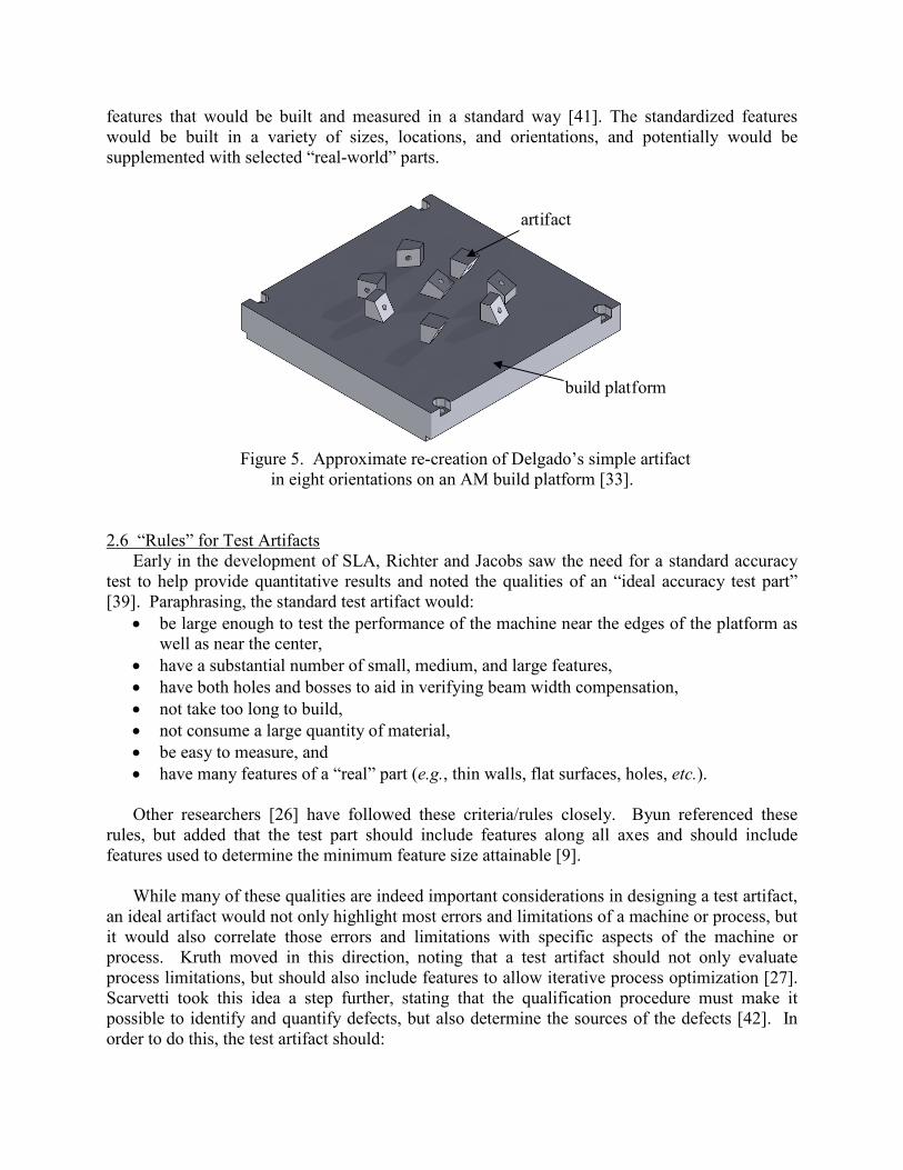
One alternative to the square-base, multiple-feature test artifact is the use of a smaller,
simpler test artifact that is built at multiple positions and/or multiple orientations throughout the work volume (see Figure 5). A second alternative approach is the use of a standard library of 3D objects or part features (e.g., spheres, cylinders, prisms, cones, etc.), rather than a single test artifact, to evaluate AM system performance. Smith proposes a library of twelve objects to benchmark AM systems, with each object designed to demonstrate and evaluate at least one important feature of the resulting parts [40]. Jurrens suggests use of a standard library of 3D
features that would be built and measured in a standard way [41]. The standardized features would be built in a variety of sizes, locations, and orientations, and potentially would be supplemented with selected “real-world” parts.
Figure 5. Approximate re-creation of Delgado’s simple artifact
in eight orientations on an AM build platform [33].
2.6 “Rules” for Test Artifacts Early in the development of SLA, Richter and Jacobs saw the need for a standard accuracy
test to help provide quantitative results and noted the qualities of an “ideal accuracy test part” [39]. Paraphrasing, the standard test artifact would:
• be large enough to test the performance of the machine near the edges of the platform as well as near the center,
• have a substantial number of small, medium, and large features, • have both holes and bosses to aid in verifying beam width compensation, • not take too long to build, • not consume a large quantity of material, • be easy to measure, and • have many features of a “real” part (e.g., thin walls, flat surfaces, holes, etc.).
Other researchers [26] have followed these criteria/rules closely. Byun referenced these
rules, but added that the test part should include features along all axes and should include features used to determine the minimum feature size attainable [9].
While many of these qualities are indeed important considerations in designing a test artifact,
an ideal artifact would not only highlight most errors and limitations of a machine or process, but it would also correlate those errors and limitations with specific aspects of the machine or process. Kruth moved in this direction, noting that a test artifact should not only evaluate process limitations, but should also include features to allow iterative process optimization [27]. Scarvetti took this idea a step further, stating that the qualification procedure must make it possible to identify and quantify defects, but also determine the sources of the defects [42]. In order to do this, the test artifact should:
artifact
build platform
• have simple geometrical shapes, allowing perfect definition and easy control of the geometry,
• require no post-treatment or manual intervention (e.g., there should be no support structures), and
• allow repeatability measurements [42]. In addition, several researchers state or imply the need for a test artifact to include multiples
of the same feature to allow repeatability measurements. However, including multiples of the same feature merely tests the machine or process capability to produce that same feature at different places within the work volume; it does not test the repeatability of the machine or process [43]. Various conditions may result in different systematic errors existing at different locations in the work volume, leading to differences in the shapes of the features produced in these positions. However, if multiple artifacts were produced, every feature produced in the same position in the work volume would be ideally the same.
Previously, the concepts of using a test artifact to highlight the capabilities and limitations of
a machine or process or to identify and quantify specific machine defects have remained mostly distinct. The current study seeks to combine the concepts into a singular artifact.
3. Design Intent
The selection and location of features in a test artifact are chosen based on the intent of the
design. The intent of most designs is to characterize the accuracy of the machine or process or to demonstrate the capabilities of the machine or process. We seek to design a test artifact that is capable of highlighting the capabilities and limitations of a machine or process, quantifying the accuracy of a machine or process, and diagnosing specific defects in the machine. The following subsections explain criteria for demonstrating capabilities and limitations of a machine or process, criteria for identifying and quantifying machine errors, and some general considerations. A summary of the part and machine or process capability we seek to explore is given at the end of section 4.
3.1 Criteria for Demonstrating Capabilities and Limitations
To design an artifact that demonstrates capabilities and limitations of a machine or process, we must first establish certain “required” AM system capabilities. These capabilities should verify that the system is (or is not) capable of producing a desired “real world” part, and should also show unique aspects of the process. Eight items are of primary importance. An AM system should be able to create: straight features (both paraxial and askew), parallel and perpendicular features, circular and arced features, fine features (i.e., minimum feature size attainable), and freeform features. The system should be able to produce these features as both holes (cavities) and bosses (free standing structures). It should be able to create these features not just in the horizontal plane (parallel to the build platform, the x-y plane), but also in the vertical planes as well (i.e., overhangs). The system should be able to produce these features in the correct locations and orientations.
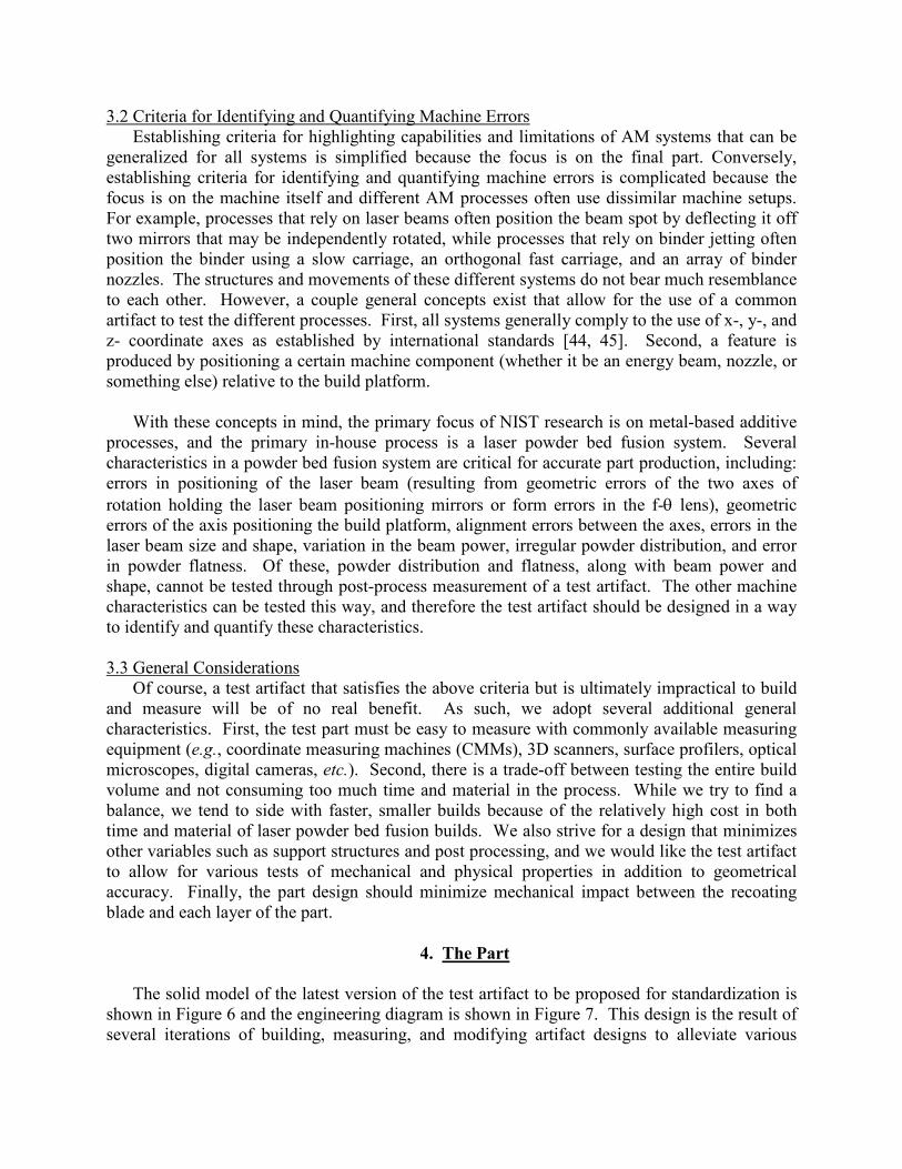
3.2 Criteria for Identifying and Quantifying Machine Errors Establishing criteria for highlighting capabilities and limitations of AM systems that can be
generalized for all systems is simplified because the focus is on the final part. Conversely, establishing criteria for identifying and quantifying machine errors is complicated because the focus is on the machine itself and different AM processes often use dissimilar machine setups. For example, processes that rely on laser beams often position the beam spot by deflecting it off two mirrors that may be independently rotated, while processes that rely on binder jetting often position the binder using a slow carriage, an orthogonal fast carriage, and an array of binder nozzles. The structures and movements of these different systems do not bear much resemblance to each other. However, a couple general concepts exist that allow for the use of a common artifact to test the different processes. First, all systems generally comply to the use of x-, y-, and z- coordinate axes as established by international standards [44, 45]. Second, a feature is produced by positioning a certain machine component (whether it be an energy beam, nozzle, or something else) relative to the build platform.
With these concepts in mind, the primary focus of NIST research is on metal-based additive
processes, and the primary in-house process is a laser powder bed fusion system. Several characteristics in a powder bed fusion system are critical for accurate part production, including: errors in positioning of the laser beam (resulting from geometric errors of the two axes of rotation holding the laser beam positioning mirrors or form errors in the f-θ lens), geometric errors of the axis positioning the build platform, alignment errors between the axes, errors in the laser beam size and shape, variation in the beam power, irregular powder distribution, and error in powder flatness. Of these, powder distribution and flatness, along with beam power and shape, cannot be tested through post-process measurement of a test artifact. The other machine characteristics can be tested this way, and therefore the test artifact should be designed in a way to identify and quantify these characteristics.
3.3 General Considerations
Of course, a test artifact that satisfies the above criteria but is ultimately impractical to build and measure will be of no real benefit. As such, we adopt several additional general characteristics. First, the test part must be easy to measure with commonly available measuring equipment (e.g., coordinate measuring machines (CMMs), 3D scanners, surface profilers, optical microscopes, digital cameras, etc.). Second, there is a trade-off between testing the entire build volume and not consuming too much time and material in the process. While we try to find a balance, we tend to side with faster, smaller builds because of the relatively high cost in both time and material of laser powder bed fusion builds. We also strive for a design that minimizes other variables such as support structures and post processing, and we would like the test artifact to allow for various tests of mechanical and physical properties in addition to geometrical accuracy. Finally, the part design should minimize mechanical impact between the recoating blade and each layer of the part.
4. The Part The solid model of the latest version of the test artifact to be proposed for standardization is
shown in Figure 6 and the engineering diagram is shown in Figure 7. This design is the result of several iterations of building, measuring, and modifying artifact designs to alleviate various
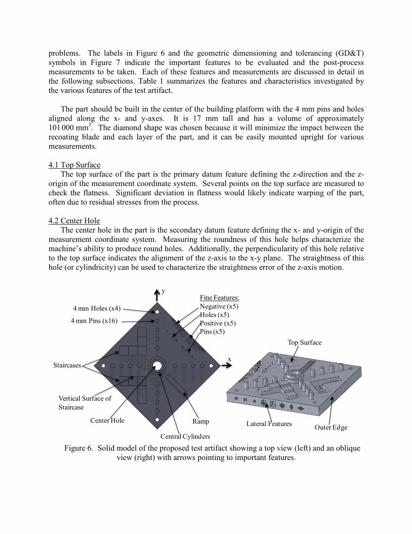
problems. The labels in Figure 6 and the geometric dimensioning and tolerancing (GD&T) symbols in Figure 7 indicate the important features to be evaluated and the post-process measurements to be taken. Each of these features and measurements are discussed in detail in the following subsections. Table 1 summarizes the features and characteristics investigated by the various features of the test artifact.
The part should be built in the center of the building platform with the 4 mm pins and holes
aligned along the x- and y-axes. It is 17 mm tall and has a volume of approximately 101 000 mm3. The diamond shape was chosen because it will minimize the impact between the recoating blade and each layer of the part, and it can be easily mounted upright for various measurements.
4.1 Top Surface
The top surface of the part is the primary datum feature defining the z-direction and the z-origin of the measurement coordinate system. Several points on the top surface are measured to check the flatness. Significant deviation in flatness would likely indicate warping of the part, often due to residual stresses from the process.
4.2 Center Hole
The center hole in the part is the secondary datum feature defining the x- and y-origin of the measurement coordinate system. Measuring the roundness of this hole helps characterize the machine’s ability to produce round holes. Additionally, the perpendicularity of this hole relative to the top surface indicates the alignment of the z-axis to the x-y plane. The straightness of this hole (or cylindricity) can be used to characterize the straightness error of the z-axis motion.
Figure 6. Solid model of the proposed test artifact showing a top view (left) and an oblique
view (right) with arrows pointing to important features.
4 mm Holes (x4)
4 mm Pins (x16)
Staircases
Vertical Surface of Staircase
Ramp
Fine Features:Negative (x5) Holes (x5)Positive (x5)Pins (x5)
Lateral FeaturesCenter Hole
Central Cylinders
Top Surface
y
x
Outer Edge
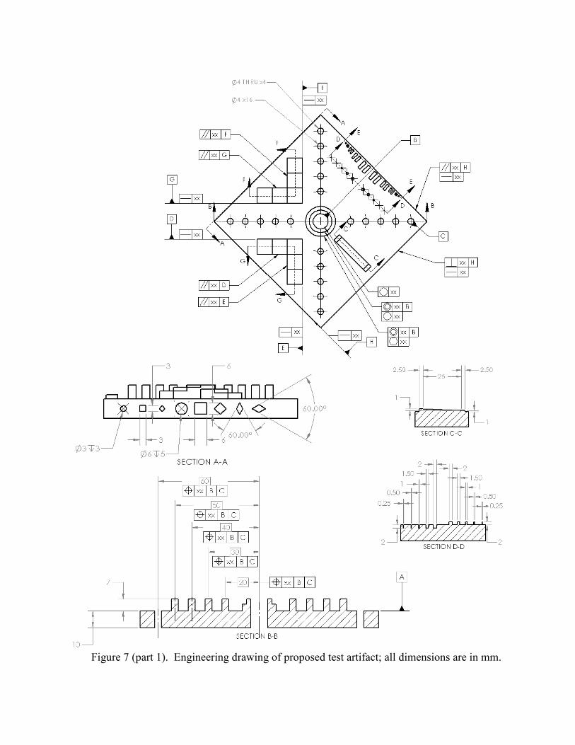
Figure 7 (part 1). Engineering drawing of proposed test artifact; all dimensions are in mm.
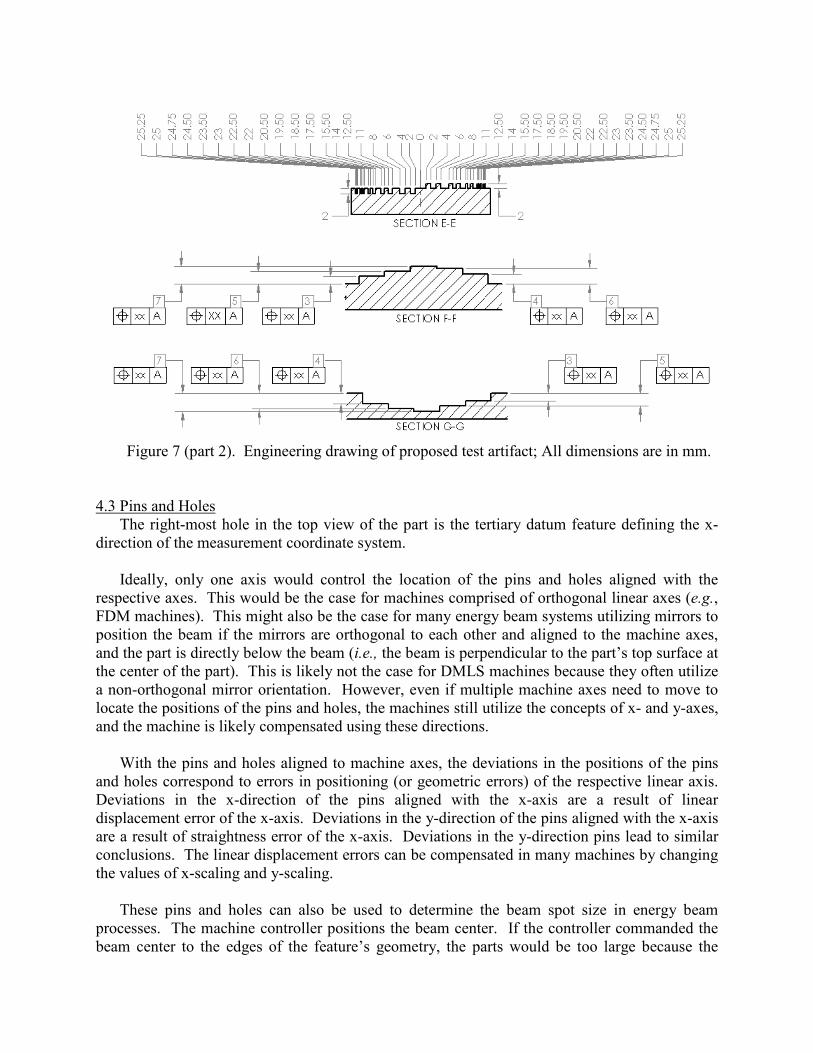
Figure 7 (part 2). Engineering drawing of proposed test artifact; All dimensions are in mm.
4.3 Pins and Holes The right-most hole in the top view of the part is the tertiary datum feature defining the x-
direction of the measurement coordinate system. Ideally, only one axis would control the location of the pins and holes aligned with the
respective axes. This would be the case for machines comprised of orthogonal linear axes (e.g., FDM machines). This might also be the case for many energy beam systems utilizing mirrors to position the beam if the mirrors are orthogonal to each other and aligned to the machine axes, and the part is directly below the beam (i.e., the beam is perpendicular to the part’s top surface at the center of the part). This is likely not the case for DMLS machines because they often utilize a non-orthogonal mirror orientation. However, even if multiple machine axes need to move to locate the positions of the pins and holes, the machines still utilize the concepts of x- and y-axes, and the machine is likely compensated using these directions.
With the pins and holes aligned to machine axes, the deviations in the positions of the pins
and holes correspond to errors in positioning (or geometric errors) of the respective linear axis. Deviations in the x-direction of the pins aligned with the x-axis are a result of linear displacement error of the x-axis. Deviations in the y-direction of the pins aligned with the x-axis are a result of straightness error of the x-axis. Deviations in the y-direction pins lead to similar conclusions. The linear displacement errors can be compensated in many machines by changing the values of x-scaling and y-scaling.
These pins and holes can also be used to determine the beam spot size in energy beam
processes. The machine controller positions the beam center. If the controller commanded the beam center to the edges of the feature’s geometry, the parts would be too large because the
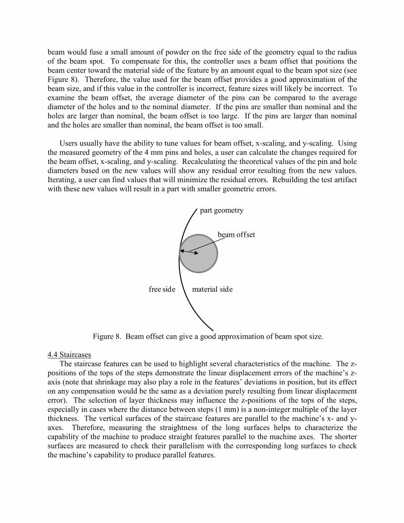
beam would fuse a small amount of powder on the free side of the geometry equal to the radius of the beam spot. To compensate for this, the controller uses a beam offset that positions the beam center toward the material side of the feature by an amount equal to the beam spot size (see Figure 8). Therefore, the value used for the beam offset provides a good approximation of the beam size, and if this value in the controller is incorrect, feature sizes will likely be incorrect. To examine the beam offset, the average diameter of the pins can be compared to the average diameter of the holes and to the nominal diameter. If the pins are smaller than nominal and the holes are larger than nominal, the beam offset is too large. If the pins are larger than nominal and the holes are smaller than nominal, the beam offset is too small.
Users usually have the ability to tune values for beam offset, x-scaling, and y-scaling. Using
the measured geometry of the 4 mm pins and holes, a user can calculate the changes required for the beam offset, x-scaling, and y-scaling. Recalculating the theoretical values of the pin and hole diameters based on the new values will show any residual error resulting from the new values. Iterating, a user can find values that will minimize the residual errors. Rebuilding the test artifact with these new values will result in a part with smaller geometric errors.
Figure 8. Beam offset can give a good approximation of beam spot size.
4.4 Staircases
The staircase features can be used to highlight several characteristics of the machine. The z- positions of the tops of the steps demonstrate the linear displacement errors of the machine’s z-axis (note that shrinkage may also play a role in the features’ deviations in position, but its effect on any compensation would be the same as a deviation purely resulting from linear displacement error). The selection of layer thickness may influence the z-positions of the tops of the steps, especially in cases where the distance between steps (1 mm) is a non-integer multiple of the layer thickness. The vertical surfaces of the staircase features are parallel to the machine’s x- and y-axes. Therefore, measuring the straightness of the long surfaces helps to characterize the capability of the machine to produce straight features parallel to the machine axes. The shorter surfaces are measured to check their parallelism with the corresponding long surfaces to check the machine’s capability to produce parallel features.
part geometry
material sidefree side
beam offset
4.5 Outer Edges The straightness of the three outer edge features that do not contain lateral features are
measured to characterize the machine’s capability to produce straight features askew from the machine axes.
4.6 Central Cylinders
The roundness values of the central cylinders characterize the ability of the machine to produce round or arced bosses, while the concentricity of these two bosses with the central hole characterizes the machine’s ability to produce concentric features.
4.7 Ramp
The ramp is designed to slope constantly with a 1 mm rise over a 25 mm run. However, the discrete layer thickness of any AM process will result in a stair-step effect on the manufactured ramp. The value of the designed slope was chosen so that even machines with small layer thicknesses will still produce the ramp feature with visible stair-stepping, allowing measurement of individual stair-steps with a stylus profilometer or other device. For example, a process utilizing 20 µm layers will produce a ramp with 0.5 mm step landings. The measured profile will help characterize the machine’s ability to produce 3D contours. Alternatively, the roughness of the ramp can be measured with a surface profiler and also give a similar characterization. Additionally, the z-positions of individual stair-steps can be examined to give further characterization of the machine’s z-axis linear displacement error.
4.8 Fine Features
There are two different sets of fine features. The first set (closer to the outer edge of the part and shown in section EE of Figure 7 (part 2)) is of neighboring rectangular bosses or holes. These features help to establish the minimum required separation of features as well as the minimum size of rectangular holes and bosses. The second set of fine features is comprised of the pins and holes shown in section DD of Figure 7 (part 1). These features are intended to establish the minimum feature size achievable by the machine. In both sets, the widths of the fine features descend from 2 mm to 0.25 mm from the center of the set outward. All features are 2 mm tall or deep.
The measurement of these fine features is intended to be by optical microscope. The small
sizes of the features inhibit access by a typical CMM probe. Visual inspection by microscope does not provide a value for dimensional accuracy (as in measurement by CMM), but the microscope images (usually at no more than 5x magnification) give an adequate indication of whether or not the feature was successfully built. The fine features of the first set are located close to the edge of the part so that the part can be oriented vertically, and these features can be inspected in profile (if the top view of the features is ambiguous). The final result should be a successfully built feature of one size and an unsuccessfully built feature at the next smaller size. This provides a range within which resides the actual minimum feature size attainable. Note that an optical CMM or a calibrated optical microscope could provide dimensional accuracy of the features as well.
4.9 Lateral Features Whenever possible, lateral features in the test artifact should be produced without support
structures. These features were designed with small lateral depths so that a failure to properly build the part would not result in significant damage to the production process. While a lack of support may result in poor geometry of these features, their failure often reveals important information about the performance of the process. Failure to properly build these features in a powder bed fusion process is more often due to poor heat transfer rather than poor structural support, evidenced by singeing at the upper surfaces of these features [46]. Further, if some of the lateral features are well-built without support structures, and others are poorly built without support structures, a user can better understand design rules for when to use supports (e.g., the different shaped diamonds can help provide rules for the minimum draft angle requiring support).
The intent of the test artifact makes support structures problematic for several reasons. From
a machine characterization point of view, the requirement for the post-process removal of support structures adds ambiguity to the source of deviations in feature geometry, because it may be difficult to de-couple errors from the AM process and errors from the post-process technique. Additionally, from a standardization point of view, a strategy for defining support structures would need to be unambiguous and universally available to ensure all users properly employ it.
Lateral features can be examined qualitatively by eye (or digital camera), and they can be
measured by CMM or other measuring device for dimensional accuracy. The resulting geometry of the lateral features combine with the results of the ramp feature to better characterize the ability of the machine to produce 3D contours. For example, examining build quality of the diamond shaped lateral features and combining the severity of the stair-stepping of the ramp feature, a user can make a more informed decision on the ability of the machine to produce a “real world” feature like a threaded hole.
4.10 Other Tests
In addition to measuring the test artifact for geometric accuracy, the test artifact can be measured to obtain other information about the part and process. Obviously many areas on the top surface or sides of the part can be examined by a surface profiler to measure surface roughness. The part is intended to be built solid to allow various measurements for physical and mechanical properties. Ultrasonic testing (UT) for porosity and measurement of material moduli can be performed using a small contact transducer on the top step of the positive staircase structure. Samples can be cut off the part and machined into tension testing bars. Small samples can be cut off the part (e.g., any of the pins) and measured by x-ray computed tomography (CT) or prepared by common metallographic techniques to examine microstructures of the samples.
4.11 Summary
Table 1 summarizes the characteristics of the machine or process being investigated by the various features of the test artifact.
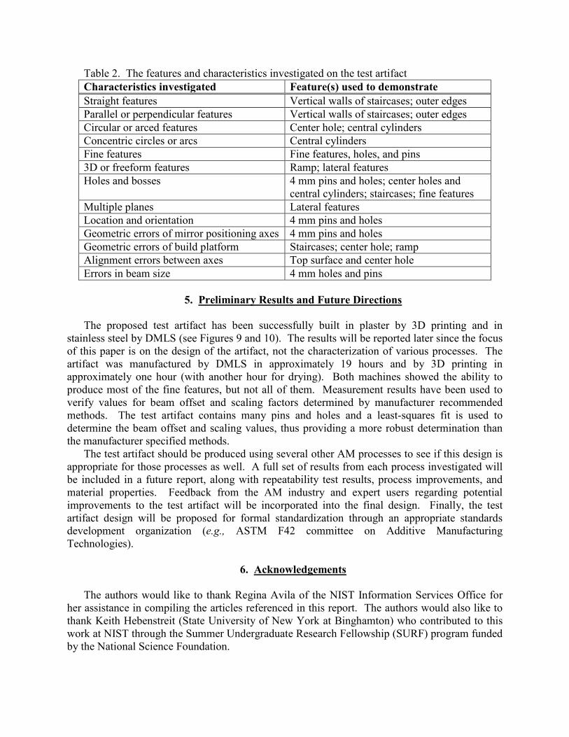
Table 2. The features and characteristics investigated on the test artifact Characteristics investigated Feature(s) used to demonstrate Straight features Vertical walls of staircases; outer edges Parallel or perpendicular features Vertical walls of staircases; outer edges Circular or arced features Center hole; central cylinders Concentric circles or arcs Central cylinders Fine features Fine features, holes, and pins 3D or freeform features Ramp; lateral features Holes and bosses 4 mm pins and holes; center holes and
central cylinders; staircases; fine features Multiple planes Lateral features Location and orientation 4 mm pins and holes Geometric errors of mirror positioning axes 4 mm pins and holes Geometric errors of build platform Staircases; center hole; ramp Alignment errors between axes Top surface and center hole Errors in beam size 4 mm holes and pins
5. Preliminary Results and Future Directions
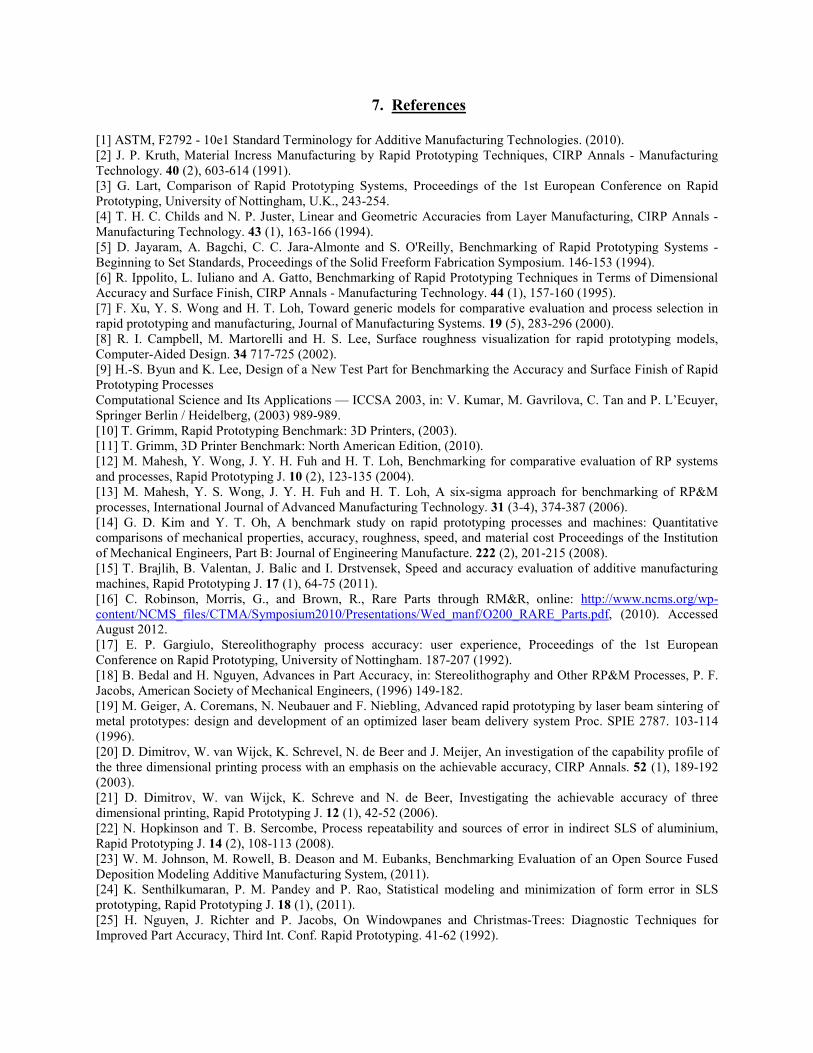
The proposed test artifact has been successfully built in plaster by 3D printing and in
stainless steel by DMLS (see Figures 9 and 10). The results will be reported later since the focus of this paper is on the design of the artifact, not the characterization of various processes. The artifact was manufactured by DMLS in approximately 19 hours and by 3D printing in approximately one hour (with another hour for drying). Both machines showed the ability to produce most of the fine features, but not all of them. Measurement results have been used to verify values for beam offset and scaling factors determined by manufacturer recommended methods. The test artifact contains many pins and holes and a least-squares fit is used to determine the beam offset and scaling values, thus providing a more robust determination than the manufacturer specified methods.
The test artifact should be produced using several other AM processes to see if this design is appropriate for those processes as well. A full set of results from each process investigated will be included in a future report, along with repeatability test results, process improvements, and material properties. Feedback from the AM industry and expert users regarding potential improvements to the test artifact will be incorporated into the final design. Finally, the test artifact design will be proposed for formal standardization through an appropriate standards development organization (e.g., ASTM F42 committee on Additive Manufacturing Technologies).
6. Acknowledgements
The authors would like to thank Regina Avila of the NIST Information Services Office for
her assistance in compiling the articles referenced in this report. The authors would also like to thank Keith Hebenstreit (State University of New York at Binghamton) who contributed to this work at NIST through the Summer Undergraduate Research Fellowship (SURF) program funded by the National Science Foundation.
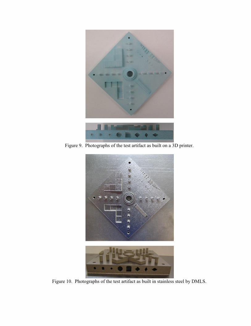
Figure 9. Photographs of the test artifact as built on a 3D printer.
Figure 10. Photographs of the test artifact as built in stainless steel by DMLS.
7. References
[1] ASTM, F2792 - 10e1 Standard Terminology for Additive Manufacturing Technologies. (2010). [2] J. P. Kruth, Material Incress Manufacturing by Rapid Prototyping Techniques, CIRP Annals - Manufacturing Technology. 40 (2), 603-614 (1991). [3] G. Lart, Comparison of Rapid Prototyping Systems, Proceedings of the 1st European Conference on Rapid Prototyping, University of Nottingham, U.K., 243-254. [4] T. H. C. Childs and N. P. Juster, Linear and Geometric Accuracies from Layer Manufacturing, CIRP Annals - Manufacturing Technology. 43 (1), 163-166 (1994). [5] D. Jayaram, A. Bagchi, C. C. Jara-Almonte and S. O'Reilly, Benchmarking of Rapid Prototyping Systems - Beginning to Set Standards, Proceedings of the Solid Freeform Fabrication Symposium. 146-153 (1994). [6] R. Ippolito, L. Iuliano and A. Gatto, Benchmarking of Rapid Prototyping Techniques in Terms of Dimensional Accuracy and Surface Finish, CIRP Annals - Manufacturing Technology. 44 (1), 157-160 (1995). [7] F. Xu, Y. S. Wong and H. T. Loh, Toward generic models for comparative evaluation and process selection in rapid prototyping and manufacturing, Journal of Manufacturing Systems. 19 (5), 283-296 (2000). [8] R. I. Campbell, M. Martorelli and H. S. Lee, Surface roughness visualization for rapid prototyping models, Computer-Aided Design. 34 717-725 (2002). [9] H.-S. Byun and K. Lee, Design of a New Test Part for Benchmarking the Accuracy and Surface Finish of Rapid Prototyping Processes Computational Science and Its Applications — ICCSA 2003, in: V. Kumar, M. Gavrilova, C. Tan and P. L’Ecuyer, Springer Berlin / Heidelberg, (2003) 989-989. [10] T. Grimm, Rapid Prototyping Benchmark: 3D Printers, (2003). [11] T. Grimm, 3D Printer Benchmark: North American Edition, (2010). [12] M. Mahesh, Y. Wong, J. Y. H. Fuh and H. T. Loh, Benchmarking for comparative evaluation of RP systems and processes, Rapid Prototyping J. 10 (2), 123-135 (2004). [13] M. Mahesh, Y. S. Wong, J. Y. H. Fuh and H. T. Loh, A six-sigma approach for benchmarking of RP&M processes, International Journal of Advanced Manufacturing Technology. 31 (3-4), 374-387 (2006). [14] G. D. Kim and Y. T. Oh, A benchmark study on rapid prototyping processes and machines: Quantitative comparisons of mechanical properties, accuracy, roughness, speed, and material cost Proceedings of the Institution of Mechanical Engineers, Part B: Journal of Engineering Manufacture. 222 (2), 201-215 (2008). [15] T. Brajlih, B. Valentan, J. Balic and I. Drstvensek, Speed and accuracy evaluation of additive manufacturing machines, Rapid Prototyping J. 17 (1), 64-75 (2011). [16] C. Robinson, Morris, G., and Brown, R., Rare Parts through RM&R, online: http://www.ncms.org/wp-content/NCMS_files/CTMA/Symposium2010/Presentations/Wed_manf/O200_RARE_Parts.pdf, (2010). Accessed August 2012. [17] E. P. Gargiulo, Stereolithography process accuracy: user experience, Proceedings of the 1st European Conference on Rapid Prototyping, University of Nottingham. 187-207 (1992). [18] B. Bedal and H. Nguyen, Advances in Part Accuracy, in: Stereolithography and Other RP&M Processes, P. F. Jacobs, American Society of Mechanical Engineers, (1996) 149-182. [19] M. Geiger, A. Coremans, N. Neubauer and F. Niebling, Advanced rapid prototyping by laser beam sintering of metal prototypes: design and development of an optimized laser beam delivery system Proc. SPIE 2787. 103-114 (1996). [20] D. Dimitrov, W. van Wijck, K. Schrevel, N. de Beer and J. Meijer, An investigation of the capability profile of the three dimensional printing process with an emphasis on the achievable accuracy, CIRP Annals. 52 (1), 189-192 (2003). [21] D. Dimitrov, W. van Wijck, K. Schreve and N. de Beer, Investigating the achievable accuracy of three dimensional printing, Rapid Prototyping J. 12 (1), 42-52 (2006). [22] N. Hopkinson and T. B. Sercombe, Process repeatability and sources of error in indirect SLS of aluminium, Rapid Prototyping J. 14 (2), 108-113 (2008). [23] W. M. Johnson, M. Rowell, B. Deason and M. Eubanks, Benchmarking Evaluation of an Open Source Fused Deposition Modeling Additive Manufacturing System, (2011). [24] K. Senthilkumaran, P. M. Pandey and P. Rao, Statistical modeling and minimization of form error in SLS prototyping, Rapid Prototyping J. 18 (1), (2011). [25] H. Nguyen, J. Richter and P. Jacobs, On Windowpanes and Christmas-Trees: Diagnostic Techniques for Improved Part Accuracy, Third Int. Conf. Rapid Prototyping. 41-62 (1992).
[26] S. L. Campanelli, G. Cardano, R. Giannoccaro, A. D. Ludovico and E. L. J. Bohez, Statistical analysis of the stereolithographic process to improve the accuracy, Computer-Aided Design. 39 (1), 80-86 (2007). [27] J.-P. V. Kruth, B.; Van Vaerenbergh, J.; Mercelis, P. , Benchmarking of different SLS/SLM processes as rapid manufacturing techniques, Int. Conf. Polymers & Moulds Innovations (PMI), Gent, Belgium, April 20-23, 2005. (2005). [28] L. Castillo, Study about the rapid manufacturing of complex parts of stainless steel and titanium, (2005). [29] Y. Ning, Y. S. Wong, J. Y. H. Fuh and H. T. Loh, An approach to minimize build errors in direct metal laser sintering, Ieee Transactions on Automation Science and Engineering. 3 (1), 73-80 (2006). [30] K. A. Ghany and S. F. Moustafa, Comparison between the products of four RPM systems for metals, Rapid Prototyping J. 12 (2), 86-94 (2006). [31] N. Hanumaiah and B. Ravi, Rapid tooling form accuracy estimation using region elimination adaptive search based sampling technique, Rapid Prototyping J. 13 (3), 182-190 (2007). [32] E. Pessard, P. Mognol, J. Y. Hascoet and C. Gerometta, Complex cast parts with rapid tooling: rapid manufacturing point of view, International Journal of Advanced Manufacturing Technology. 39 (9-10), 898-904 (2008). [33] J. Delgado, J. Ciurana, C. Reguant and B. Cavallini, Studying the repeatability in DMLS technology using a complete geometry test part. (2010). [34] A. L. Cooke and J. A. Soons, Variability in the Geometric Accuracy of Additively Manufactured Test Parts, 21st Annual International Solid Freeform Fabrication Symposium, Austin, Texas, USA, 1-12. [35] P. M. Pandey, N. V. Reddy and S. G. Dhande, Improvement of surface finish by staircase machining in fused deposition modeling, Journal of Materials Processing Technology. 132 (1-3), 323-331 (2003). [36] A. Armillotta, Assessment of surface quality on textured FDM prototypes, Rapid Prototyping J. 12 (1), 35-41 (2006). [37] O. S. Es-Said, J. Foyos, R. Noorani, M. Mendelson, R. Marloth and B. A. Pregger, Effect of layer orientation on mechanical properties of rapid prototyped samples, Mater. Manuf. Process. 15 (1), 107-122 (2000). [38] V. Vega, J. Clements, T. Lam, A. Abad, B. Fritz, N. Ula and O. S. Es-Said, The Effect of Layer Orientation on the Mechanical Properties and Microstructure of a Polymer, Journal of Materials Engineering and Performance. 20 (6), 978-988 (2011). [39] J. Richter and P. Jacobs, Accuracy, in: Rapid Prototyping & Manufacturing, P. Jacobs, Society of Manufacturing Engineers, (1992) 287-315. [40] R. Smith, Standard Test-Files for Benchmarking RP Systems, Third International Conference on Rapid Prototyping. (1992). [41] K. K. Jurrens, Standards for the Rapid Prototyping Industry, Rapid Prototyping J. 5 (4), 169-178 (1999). [42] D. Scaravetti, P. Dubois and R. Duchamp, Qualification of rapid prototyping tools: proposition of a procedure and a test part, The International Journal of Advanced Manufacturing Technology. 38 (7), 683-690 (2008). [43] M. Shellabear, Model manufacturing processes--State of the art in rapid prototyping, RAPTEC Task 4.2, Report 1. (1998). [44] ISO, 841: Industrial automation systems and integration--Numerical control of machines--Coordinate system and motion nomenclature, [45] ASTM, F2921-11: Standard Terminology for Additive Manufacturing--Coordinate Systems and Test Methodologies. [46] J. P. Kruth, P. Mercelis, J. Van Vaerenbergh and T. Craeghs, Feedback control of selective laser melting, Proceedings of the 3rd International Conference on Advanced Research in Virtual and Rapid Prototyping, Leiria, Portugal. 521-527 (2008).