Embed Size (px)
Citation preview
RE 29014 edition 2015-05 Bosch Rexroth AG
Proportional directional valve direct operated with pQ functionality
Features
3-way proportional directional valve with integrated IAC-P digital control electronics
Completely adjusted unit consisting of position-con-trolled valve pressure sensor and field bus connection
Operation via a proportional solenoid with central thread and detachable coil
Valve spool position-controlled Integrated pressure sensor plate (optional) ISO 4401 porting pattern Analog interfaces for command and actual values Design for CAN bus with DS 408 CANopen protocol or
DP Profibus Quick commissioning via PC and WINPED commission-
ing software
Sizes 6 and 10 Component series 1X 2X
RE 29014thinspEdition 2015-05Replaces 2013-03
H8064
Type STW 0195 and STW 0196
Contents
Features 1Ordering code 2Symbols 2Set-up function section 3Technical data 4 5Characteristic curves 6 8Performance limits 9 10Dimensions 11 13Electrical connections assignment 14 15Accessories 16 17Project planning and maintenance instructions 18Further information 18
Contents
Features 1Ordering codes 2Symbols 2Set-up function section 3Technical data (For applications outside these parameters please consult us) 4Technical data (For applications outside these parameters please consult us) 5Characteristic curves Size 6 (ldquo0195hellip1rdquo) (measured with HLP46 ϑOil = 40 plusmn 5 degC) 6Characteristic curves Size 10 (ldquo0196hellip1rdquo) (measured with HLP46 ϑOil = 40 plusmn 5 degC) 6Characteristic curves (measured with HLP46 ϑOil = 40 plusmn 5 degC) 7Characteristic curves Size 6 (ldquo0195helliprdquo) (measured with HLP46 ϑOil = 40 plusmn 5 degC) 8Characteristic curves Size 10 (ldquo0196rdquo) (measured with HLP46 ϑOil = 40 plusmn 5 degC) 8Performance limits Size 6 (ldquo0195helliprdquo) (measured with HLP46 ϑOil = 40 plusmn 5 degC) 9Performance limits Size 10 (ldquo0196rdquo) (measured with HLP46 ϑOil = 40 plusmn 5 degC) 10Dimensions Size 6 (ldquo0195rdquo) (dimensions in mm) 11Dimensions Size 10 (ldquo0196rdquo) (dimensions in mm) 12Dimensions 13Electrical connections assignment 14Electrical connections assignment 15Accessories (separate order) 163 161 162 16Accessories (separate order) 17Project planning and maintenance instructions 18Further information 18Notes 19Notes 20
218 STW 0195 STW 0196 | Proportional directional valve
Bosch Rexroth AG RE 29014 edition 2015-05
Ordering codes
01 3-way proportional directional valve with integrated IAC-P digital control electronics STW
02 Size 6 0195Size 10 0196
03 Component series 10 hellip 19 (10 hellip 19 unchanged installation and connection dimensions) - size 10 1XComponent series 20 hellip 29 (20 hellip 29 unchanged installation and connection dimensions) - size 6 2X
Rated flow04 ndash Size 6 (model ldquo0195rdquo)
P rarr A 10 lmin A rarr T 20 lmin 1P rarr A 20 lmin A rarr T 20 lmin 2ndash Size 10 (model ldquo0196rdquo)P rarr A 65 lmin A rarr T 60 lmin B rarr T 60 lmin 1
Seal material05 FKM seals V
Observe compatibility of seals with hydraulic fluid used (Other seals upon request)
Pressure rating of the integrated pressure sensor06 Nominal pressure 50 bar 3
Nominal pressure 160 bar 5Nominal pressure 250 bar 8
Supply voltage07 Direct voltage 24 V 24
Bus interface08 CANBus DS - 408 C
Profibus DP V0V1 P
Interface09 plusmn 10 VDC A6
4 hellip 20 mA F6
10 Further details in the plain text
01 02 03 04 05 06 07 08 09 10
STW ndash V ndash 24 ndash
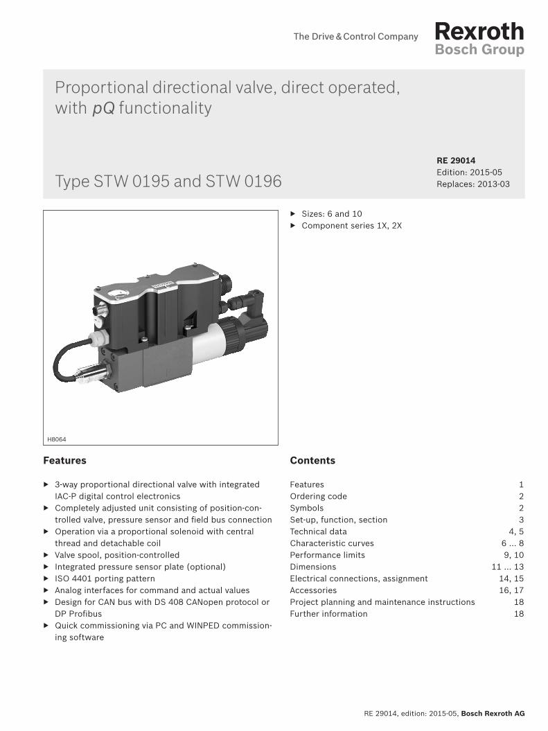
Symbols
Version ldquo0195rdquo Version ldquo0196rdquo
Proportional directional valve | STW 0195 STW 0196 318
RE 29014 edition 2015-05 Bosch Rexroth AG
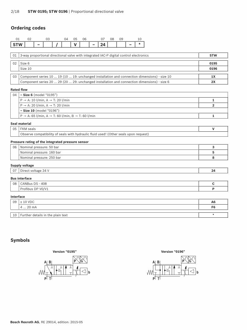
Set-up function section
Set-up The IAC-P valve basically consists of Housing (1) with connection surface Control spool (2) with compression spring (3) Solenoid and pole tube (4) with central thread Position transducer (5) Pressure sensor (6) Integrated IAC-P digital control electronics (7) with
bus connection (X2) and central connector (X1)
Functional description If solenoids (4) are not operated spool position A rarr T
(with type STW 0196-1X1 additionally B rarr T) Functions
ndash Flow control (Q) ndash Pressure control (p) ndash Override control pQ
The command value can be defined either via an analog interface (X1) or via the field bus interface (X2 X3)
The actual value signals are provided via an analog interface (X1) and may be read additionally via the field bus (X2 X3)
The controller parameters are set via the field bus (X2 X3)
Separate supply voltage for buscontroller and power part (output stage) for safety reasons
Type STW0195-2Xhellip
The digital integrated control electronics enables the following fault detection (diagnostics)
Cable break of pressure sensor supply line (6) Undervoltage Cable break position transducer (5) Communication error Watchdog Cable break of command value inputs
The following additional functions are available Pressure ramp Internal command value profile Release function analogdigital Error output 24 V
WINPED PC programTo implement the project planning task and to parameter-ize the IAC-P valves the user may use the WINPED com-missioning software (see accessories)
Parameterization Diagnostics Comfortable data administration on a PC PC operating systems Windows 2000 or Windows XP
Qcommand Q control p closed-loop controllt 12 mA A rarr T inactivegt 12 mA Override closed-loop control (A rarr T or P rarr A)
Q control (Qcommand) with pressure limitation (pcommand) if pressure limitation is active the following
applies Qactual le Qcommand
1) Only available with Profibus
NoticeDue to the design principle internal leakage is inherent to the valves which may increase over the life cycle The tank line must not be allowed to run empty If required by the installation conditions use a suitable preload valve
NoticeThe PG fitting (8) must not be opened Mechanical adjustment of the adjustment nut located below is prohibited and damages the valve
418 STW 0195 STW 0196 | Proportional directional valve
Bosch Rexroth AG RE 29014 edition 2015-05
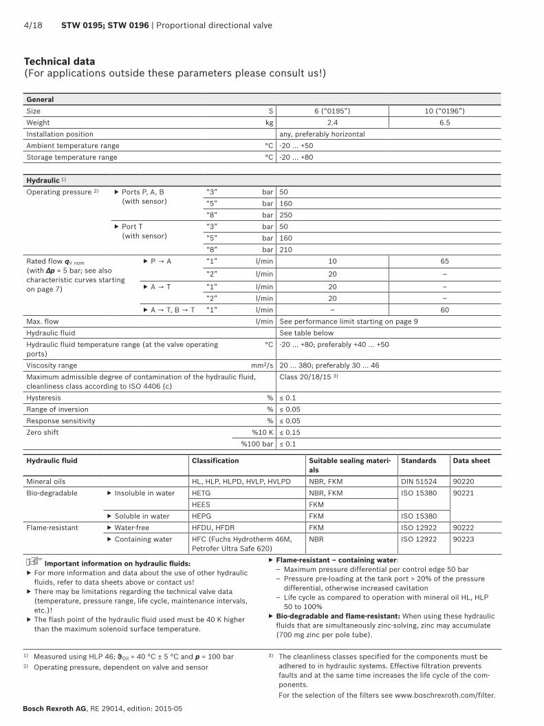
GeneralSize S 6 (ldquo0195rdquo) 10 (ldquo0196rdquo)Weight kg 24 65Installation position any preferably horizontalAmbient temperature range degC -20 hellip +50Storage temperature range degC -20 hellip +80
Hydraulic 1)
Operating pressure 2) Ports P A B (with sensor)
ldquo3rdquo bar 50ldquo5rdquo bar 160ldquo8rdquo bar 250
Port T (with sensor)
ldquo3rdquo bar 50ldquo5rdquo bar 160ldquo8rdquo bar 210
Rated flow qV nom (with ∆p = 5 bar see also characteristic curves starting on page 7)
P rarr A ldquo1rdquo lmin 10 65
ldquo2rdquo lmin 20 ndash
A rarr T ldquo1rdquo lmin 20 ndashldquo2rdquo lmin 20 ndash
A rarr T B rarr T ldquo1rdquo lmin ndash 60Max flow lmin See performance limit starting on page 9Hydraulic fluid See table belowHydraulic fluid temperature range (at the valve operating ports)
degC -20 +80 preferably +40 +50
Viscosity range mm2s 20 380 preferably 30 46Maximum admissible degree of contamination of the hydraulic fluid cleanliness class according to ISO 4406 (c)
Class 201815 3)
Hysteresis le 01Range of inversion le 005Response sensitivity le 005Zero shift 10 K le 015
100 bar le 01
1) Measured using HLP 46 ϑOil = 40 degC plusmn 5 degC and p = 100 bar2) Operating pressure dependent on valve and sensor
Technical data (For applications outside these parameters please consult us)
Hydraulic fluid Classification Suitable sealing materi-als
Standards Data sheet
Mineral oils HL HLP HLPD HVLP HVLPD NBR FKM DIN 51524 90220Bio-degradable Insoluble in water HETG NBR FKM ISO 15380 90221
HEES FKM Soluble in water HEPG FKM ISO 15380
Flame-resistant Water-free HFDU HFDR FKM ISO 12922 90222 Containing water HFC (Fuchs Hydrotherm 46M
Petrofer Ultra Safe 620)NBR ISO 12922 90223
Important information on hydraulic fluids For more information and data about the use of other hydraulic fluids refer to data sheets above or contact us
There may be limitations regarding the technical valve data (temperature pressure range life cycle maintenance intervals etc)
The flash point of the hydraulic fluid used must be 40 K higher than the maximum solenoid surface temperature
Flame-resistant ndash containing water ndash Maximum pressure differential per control edge 50 bar ndash Pressure pre-loading at the tank port gt 20 of the pressure differential otherwise increased cavitation
ndash Life cycle as compared to operation with mineral oil HL HLP 50 to 100
Bio-degradable and flame-resistant When using these hydraulic fluids that are simultaneously zinc-solving zinc may accumulate (700 mg zinc per pole tube)
3) The cleanliness classes specified for the components must be adhered to in hydraulic systems Effective filtration prevents faults and at the same time increases the life cycle of the com-ponents
For the selection of the filters see wwwboschrexrothcomfilter
Proportional directional valve | STW 0195 STW 0196 518
RE 29014 edition 2015-05 Bosch Rexroth AG
Technical data (For applications outside these parameters please consult us)
electricalSupply voltage Nominal voltage VDC 24
Lower limit value VDC 194 Upper limit value VDC 35
Maximum admissible residual ripple Vpp 2Current consumption
Imax A 2 Impulse current A 3
Command value signals mA 4 20 (or via CAN bus)Duty cycle 1) 100Maximum coil temperature 2) degC 150Protection class according to DIN EN 60529 IP 65 with mating connector correctly mounted and locked
1) Connect the valve to the supply voltage only when this is required for the functional processes of the machine
2) Due to the surface temperatures of the solenoid coils the standards ISO 13732-1 and ISO 4413 need to be adhered to
3) related to the complete measurement range including non-lin-earity hysteresis zero point and end value deviation (corresponds to the measuring deviation according to IEC 61298-2)
Sensor technologyMeasurement range pN bar 50 160 250Overload protection pmax bar 110 320 500Bursting pressure p bar 200 640 1000Temperature coefficient for zero point and range within the nominal temperature range 3)
lt 01 10 K
Characteristic curve deviation
lt 02
Hysteresis lt 01Repetition accuracy lt 005Setting time (10 90) t lt 1 msLong-term drift (1 year) under reference conditions lt 01Conformity CE according EMC directive EN 61000-6-2 EN 61326-2-3 and
EN 61000-6-3 EN 61326-2-3
618 STW 0195 STW 0196 | Proportional directional valve
Bosch Rexroth AG RE 29014 edition 2015-05
Characteristic curves Size 6 (ldquo0195hellip1rdquo) (measured with HLP46 ϑOil = 40 plusmn 5 degC)
Characteristic curves Size 10 (ldquo0196hellip1rdquo) (measured with HLP46 ϑOil = 40 plusmn 5 degC)
Transition function (A rarr T)
Transition function (A rarr T and B rarr T)
Stro
ke in
rarr
Stro
ke in
rarr
Stro
ke in
rarr
Stro
ke in
rarr
Time in ms rarr
Time in ms rarr
Time in ms rarr
Time in ms rarr
Transition function (P rarr A)
Transition function (P rarr A)
Proportional directional valve | STW 0195 STW 0196 718
RE 29014 edition 2015-05 Bosch Rexroth AG
Characteristic curves (measured with HLP46 ϑOil = 40 plusmn 5 degC)
Frequency response Size 6 (ldquo0195hellip1rdquo)
Frequency response Size 10 (ldquo0196hellip1rdquo)
Ampl
itude
rat
io in
dB
rarr
Frequency in Hz rarr
Phas
e an
gle
in
rarr
Ampl
itude
rat
io in
dB
rarr
Frequency in Hz rarr
Phas
e an
gle
in
rarr
Signal plusmn 10
Signal plusmn 25
Signal plusmn 100
Signal plusmn 10
Signal plusmn 25
Signal plusmn 100
818 STW 0195 STW 0196 | Proportional directional valve
Bosch Rexroth AG RE 29014 edition 2015-05
Characteristic curves Size 6 (ldquo0195helliprdquo) (measured with HLP46 ϑOil = 40 plusmn 5 degC)
Flow characteristic curve (A rarr T ∆p = 5 bar)
Command value in rarr
Flow
in l
min
rarr
Command value in rarr
Flow
in l
min
rarr
Flow characteristic curve (P rarr A ∆p = 5 bar)
Characteristic curves Size 10 (ldquo0196rdquo) (measured with HLP46 ϑOil = 40 plusmn 5 degC)
Flow characteristic curve (AB rarr T ∆p = 5 bar) Flow characteristic curve (P rarr A ∆p = 5 bar)
Command value in rarr
Flow
in l
min
rarr
Command value in rarr
Flow
in l
min
rarr
3 A rarr T4 B rarr T
1 Version ldquo0195hellip1rdquo)2 Version ldquo0195hellip2rdquo)
Proportional directional valve | STW 0195 STW 0196 918
RE 29014 edition 2015-05 Bosch Rexroth AG
Performance limits Size 6 (ldquo0195helliprdquo) (measured with HLP46 ϑOil = 40 plusmn 5 degC)
Position-controlled (P rarr A 10 lmin A rarr T 20 lmin ndash A rarr T)
Pressure differential in bar rarr
Flow
in l
min
rarr
Position-controlled (P rarr A 10 lmin A rarr T 20 lmin ndash P rarr A)
Pressure differential in bar rarr
Flow
in l
min
rarr
Pressure differential in bar rarr
Flow
in l
min
rarr
Pressure differential in bar rarr
Flow
in l
min
rarr
Position-controlled (P rarr A 20 lmin A rarr T 20 lmin ndash A rarr T)
Position-controlled (P rarr A 20 lmin A rarr T 20 lmin ndash P rarr A)
1018 STW 0195 STW 0196 | Proportional directional valve
Bosch Rexroth AG RE 29014 edition 2015-05
Performance limits Size 10 (ldquo0196rdquo) (measured with HLP46 ϑOil = 40 plusmn 5 degC)
Position-controlled (A rarr T)
Pressure differential in bar rarr
Flow
in l
min
rarr
Position-controlled (P rarr A)
Pressure differential in bar rarr
Flow
in l
min
rarr
Pressure differential in bar rarr
Flow
in l
min
rarr
Position-controlled (B rarr T)
001100
Rzmax 4
13
13
13
13
Proportional directional valve | STW 0195 STW 0196 1118
RE 29014 edition 2015-05 Bosch Rexroth AG
Dimensions Size 6 (ldquo0195rdquo) (dimensions in mm)
1 Valve housing2 Proportional solenoid ldquobrdquo with inductive position transducer3 Integrated digital control electronics4 Name plate5 Space required to remove the connector6 Machined valve contact surface
porting pattern according to ISO 4401-03-02-0-05Deviating from the standard
Ports P A B and T with Oslash 8 mm Locating pin not available
Subplates and valve mounting screws see page 13
NoteThe dimensions are nominal dimensions which are subject to tolerances
Required surface quality of the valve contact surface
001100
Rzmax 4
13
1218 STW 0195 STW 0196 | Proportional directional valve
Bosch Rexroth AG RE 29014 edition 2015-05
Dimensions Size 10 (ldquo0196rdquo) (dimensions in mm)
1 Valve housing2 Proportional solenoid ldquobrdquo with inductive position transducer3 Integrated digital control electronics4 Name plate5 Space required to remove the connector6 Machined valve contact surface
Porting pattern in accordance with ISO 4401-05-04-0-05Deviating from the standardPort T1 exists additionally
Subplates and valve mounting screws see page 13
NoteThe dimensions are nominal dimensions which are subject to tolerances
Required surface quality of the valve contact surface
Proportional directional valve | STW 0195 STW 0196 1318
RE 29014 edition 2015-05 Bosch Rexroth AG
Dimensions
Valve mounting screws (separate order) Size Hexagon socket head cap screws Material number6 (ldquo0195rdquo) 4 hexagon socket head cap screws ISO 4762 - M5 x 50 - 109-flZn-240h-L
tightening torque MA = 7 Nm plusmn 10R913000064
4 hexagon socket head cap screws ISO 4762 - M5 x 50Tightening torque MA = 89 Nm plusmn 10
Not in the Rexroth delivery range
10 (ldquo0196rdquo) 4 hexagon socket head cap screws ISO 4762 - M6 x 40 - 109-flZn-240h-L tightening torque MA = 125 Nm plusmn 10
R913000058
4 hexagon socket head cap screws ISO 4762 - M6 x 40 - 109 tightening torque MA = 155 Nm plusmn 10
Not in the Rexroth delivery range
NoticeThe tightening torque of the hexagon socket head cap screws refers to the maximum operating pressure
Subplates (separate order) Size Data sheet Material number
6 (ldquo0195rdquo) 45052 ndash10 (ldquo0196rdquo) 45054 ndash
1418 STW 0195 STW 0196 | Proportional directional valve
Bosch Rexroth AG RE 29014 edition 2015-05
1) Litz wire colors of the connection line for mating connector with cable set (see accessories page 17)
Electrical connections assignment
X1
Pin Core marking 1)
Interface A6 allocation Allocation Interface F6
1 1 24 VDC (u(t) = 194 V hellip 35 V) Imax = 17 A (for output stage)2 2 0 V ≙ load zero reference for pins 1 and 93 white enable input 9 35 V ≙ enable on4 yellow plusmn 10 V command value Q Re gt 50 kΩ 4 hellip 20 mA command value Q Re = 100 Ω5 green Reference for command values Q and p6 purple plusmn 10 V actual value Q 4 20 mA actual value Q (load resistance max 300 Ω)7 pink 0 10 V command value p Re gt 50 kΩ 4 20 mA command value p Re = 100 kΩ8 red 0 hellip 10 V actual value p 4 20 mA actual value p (load resistance max 300 Ω)9 brown Control voltage level as pin 1 Imax = 03 A (for signal part and bus)
10 black 0 V reference potential for pins 3 6 8 and 11 (connected with pin 2 in valve)11 blue Error output 24 V (194 V hellip 35 V) 200 mA max loadPE green-yellow Connected to cooling element and valve housing
Connector pin assignment X1 11-pole + PE according to DIN EN 175201-804
Connector pin assignment X2 CAN bus (coding A) M12 x 1 5-pole pins
Transmission rate 20 hellip 1000 kBitsBus address 1 127CAN-specific settingsBaud rate and identifier must be set via the bus system
Pin Assignment1 nc2 nc3 CAN_GND4 CAN_H5 CAN_L
X2
Connector pin assignment for Profibus DP ldquoX2rdquo ldquoX3rdquo (coding B) M12 x 1 5-pole socket pins
Pin Assignment1 +5V2 RxDTxD-N (A line)3 D GND4 RxDTxD-P (B line)5 Shield
Transmission rate up to 12 MBaudBus address 1 126Setting via DIL switch
The +5V voltage of the IAC-P is available for an external terminating resistor
X2
X3
NoticeConnect shield to PE only on the supply side
NoticeWe recommend connecting the shields on both sides via the metal housings of the plug-in connectors Using connector pins will affect the shielding effect Internal screens are not required
13
13
13
13
Proportional directional valve | STW 0195 STW 0196 1518
RE 29014 edition 2015-05 Bosch Rexroth AG
Block diagram integrated control electronics
CAN bus
Command value q
Command value p
Actual value q
Actual value p
Enable
Error output
24 V load supply
24 V signal supply
GND
Output stage supply
Microcontroller
CAN controller
Controller
Actual pressure value
Output stage off
Actual value
position
Cable break
Output stage
Oscillator demodulator
Valv
e w
ith
indu
ctiv
e po
siti
onal
tra
nsdu
cer
Command value Command value 12 to 20 mA at pin 4 and reference potential at pin 5 result in flow from P rarr ACommand value 4 to 12 mA at pin 4 and reference potential at pin 5 result in flow from A rarr T
Actual value Actual value 12 to 20 mA at pin 6 and reference potential at pin 10 result in flow from P rarr AActual value 4 to 12 mA at pin 6 and reference potential at pin 10 result in flow from A rarr T
Connection line (recommended)
up to 25 m line length for pins 1 2 and PE 075 mm2 otherwise 025 mm2
up to 50 m line length for pins 1 2 and PE 100 mm2
External diameter see sketch of mating connector
Reference for pins 4 7Reference for pins 3 6 8 11
Protective earth-ing conductor
Electrical connections assignment
Alternatively
Profibus Profibus controller
1618 STW 0195 STW 0196 | Proportional directional valve
Bosch Rexroth AG RE 29014 edition 2015-05
Accessories (separate order)
3
1
2
The following is required for the parameter-ization via PC
CANopen Profibus DP
1 interface converter (USB) VT-ZKO-USBCA-1-1XV00Material no R901071963
VT-ZKO-USBP-1-1XV00Material no R901071962
2 Commissioning software WINPEDDownload from wwwboschrexrothdeIAC
3 Connection cable 3 m D-Sub M12 coding AMaterial no R900751271
D-Sub M12 coding BMaterial no R901078053
Proportional directional valve | STW 0195 STW 0196 1718
RE 29014 edition 2015-05 Bosch Rexroth AG
Accessories (separate order)
Port X1 Mating connector for X1 Dimensions Material numberMating connector according to DIN EN 17520-804 (11-pole + PE) plastic variant
Without cable (assembly kit) R900884671With cable set 2 x 5 m 12-pole R900032356With cable set 2 x 20 m 12-pole R900860399
CAN bus (A coding)Plug-in connector for X2 View dimensions Material numberRound connector processable 5-pole M12 x 1Straight mating connector in metal design
(line diameter 6 8 mm)
R901076910
Profibus (B coding)Plug-in connector for X2 and X3 View dimensions Material numberX2Round connector processable 5-pole M12 x 1Straight mating connector in metal design
Oslash19
6
ca 61
15
4
32
(line diameter 6 8 mm)
R901075545
X3Round connector processable 5-pole M12 x 1Straight mating connector in metal design
(line diameter 6 8 mm)
R901075550
Protective cap Protective cap M12 Version Material number
R901075563
Bosch Rexroth AG RE 29014 edition 2015-05
1818 STW 0195 STW 0196 | Proportional directional valve
Bosch Rexroth AG HydraulicsZum Eisengieszliger 197816 Lohr am Main Germany Phone +49 (0) 93 52thinspthinsp18-0 documentationboschrexrothde wwwboschrexrothde
copy This document as well as the data specifications and other information set forth in it are the exclusive property of Bosch Rexroth AG It may not be reproduced or given to third parties without the consent of Bosch Rexroth AGThe data specified only serve to describe the product It cannot be used to derive statements concerning a certain condition or suitability for a certain application This information also does not release the user from the obligation of own judgment and verification It must be remembered that our products are subject to a natural process of wear and aging
Project planning and maintenance instructions
Connect the valve to the supply voltage only when this is required for the functional processes of the machine
Do not use electrical signals provided via control elec-tronics (eg ldquoNo errorrdquo signal) for switching safety-rele-vant machine functions (see also EN ISO 13849 ldquoSafety of machinery ndash safety-related parts of control systemsrdquo)
If electro-magnetic interference must be expected take appropriate measures to ensure the function (depend-ing on the application eg shielding filtration)
The devices have been tested in the plant and are sup-plied with default settings
Only complete units can be repaired Repaired devices are returned with default settings User-specific settings are not maintained The machine end-user will have to retransfer the corresponding user parameters
Further information
Subplates Data sheets 45052 45054 Hydraulic fluids on mineral oil basis Data sheet 90220 Environmentally compatible hydraulic fluids Data sheet 90221 Flame-resistant water-free hydraulic fluids Data sheet 90222 Hydraulic valves for industrial applications Data sheet 07600-B Assembly commissioning and maintenance of hydraulic systems Data sheet 07900 CANopen protocol for IFB-P and IAC-P valves protocol description Data sheet 29015-01-Z Profibus protocol for IFB and IAC-P valves protocol description Data sheet 29015-02-Z Proportional directional valves with field bus interface with and without inte-
grated axis controller (IAC-P and IFB-P) operating instructionsData sheet 29015-B
Commissioning software and documentation on the Internet wwwboschrexrothcomIAC Selection of the filters wwwboschrexrothcomfilter
Proportional directional valve | STW 0195 STW 0196 1918
RE 29014 edition 2015-05 Bosch Rexroth AG
Bosch Rexroth AG HydraulicsZum Eisengieszliger 197816 Lohr am Main Germany Phone +49 (0) 93 52thinspthinsp18-0 documentationboschrexrothde wwwboschrexrothde
copy This document as well as the data specifications and other information set forth in it are the exclusive property of Bosch Rexroth AG It may not be reproduced or given to third parties without the consent of Bosch Rexroth AGThe data specified only serve to describe the product It cannot be used to derive statements concerning a certain condition or suitability for a certain application This information also does not release the user from the obligation of own judgment and verification It must be remembered that our products are subject to a natural process of wear and aging
Notes
Bosch Rexroth AG RE 29014 edition 2015-05
2018 STW 0195 STW 0196 | Proportional directional valve
Bosch Rexroth AG HydraulicsZum Eisengieszliger 197816 Lohr am Main Germany Phone +49 (0) 93 52thinspthinsp18-0 documentationboschrexrothde wwwboschrexrothde
copy This document as well as the data specifications and other information set forth in it are the exclusive property of Bosch Rexroth AG It may not be reproduced or given to third parties without the consent of Bosch Rexroth AGThe data specified only serve to describe the product It cannot be used to derive statements concerning a certain condition or suitability for a certain application This information also does not release the user from the obligation of own judgment and verification It must be remembered that our products are subject to a natural process of wear and aging
Notes
218 STW 0195 STW 0196 | Proportional directional valve
Bosch Rexroth AG RE 29014 edition 2015-05
Ordering codes
01 3-way proportional directional valve with integrated IAC-P digital control electronics STW
02 Size 6 0195Size 10 0196
03 Component series 10 hellip 19 (10 hellip 19 unchanged installation and connection dimensions) - size 10 1XComponent series 20 hellip 29 (20 hellip 29 unchanged installation and connection dimensions) - size 6 2X
Rated flow04 ndash Size 6 (model ldquo0195rdquo)
P rarr A 10 lmin A rarr T 20 lmin 1P rarr A 20 lmin A rarr T 20 lmin 2ndash Size 10 (model ldquo0196rdquo)P rarr A 65 lmin A rarr T 60 lmin B rarr T 60 lmin 1
Seal material05 FKM seals V
Observe compatibility of seals with hydraulic fluid used (Other seals upon request)
Pressure rating of the integrated pressure sensor06 Nominal pressure 50 bar 3
Nominal pressure 160 bar 5Nominal pressure 250 bar 8
Supply voltage07 Direct voltage 24 V 24
Bus interface08 CANBus DS - 408 C
Profibus DP V0V1 P
Interface09 plusmn 10 VDC A6
4 hellip 20 mA F6
10 Further details in the plain text
01 02 03 04 05 06 07 08 09 10
STW ndash V ndash 24 ndash
Symbols
Version ldquo0195rdquo Version ldquo0196rdquo
Proportional directional valve | STW 0195 STW 0196 318
RE 29014 edition 2015-05 Bosch Rexroth AG
Set-up function section
Set-up The IAC-P valve basically consists of Housing (1) with connection surface Control spool (2) with compression spring (3) Solenoid and pole tube (4) with central thread Position transducer (5) Pressure sensor (6) Integrated IAC-P digital control electronics (7) with
bus connection (X2) and central connector (X1)
Functional description If solenoids (4) are not operated spool position A rarr T
(with type STW 0196-1X1 additionally B rarr T) Functions
ndash Flow control (Q) ndash Pressure control (p) ndash Override control pQ
The command value can be defined either via an analog interface (X1) or via the field bus interface (X2 X3)
The actual value signals are provided via an analog interface (X1) and may be read additionally via the field bus (X2 X3)
The controller parameters are set via the field bus (X2 X3)
Separate supply voltage for buscontroller and power part (output stage) for safety reasons
Type STW0195-2Xhellip
The digital integrated control electronics enables the following fault detection (diagnostics)
Cable break of pressure sensor supply line (6) Undervoltage Cable break position transducer (5) Communication error Watchdog Cable break of command value inputs
The following additional functions are available Pressure ramp Internal command value profile Release function analogdigital Error output 24 V
WINPED PC programTo implement the project planning task and to parameter-ize the IAC-P valves the user may use the WINPED com-missioning software (see accessories)
Parameterization Diagnostics Comfortable data administration on a PC PC operating systems Windows 2000 or Windows XP
Qcommand Q control p closed-loop controllt 12 mA A rarr T inactivegt 12 mA Override closed-loop control (A rarr T or P rarr A)
Q control (Qcommand) with pressure limitation (pcommand) if pressure limitation is active the following
applies Qactual le Qcommand
1) Only available with Profibus
NoticeDue to the design principle internal leakage is inherent to the valves which may increase over the life cycle The tank line must not be allowed to run empty If required by the installation conditions use a suitable preload valve
NoticeThe PG fitting (8) must not be opened Mechanical adjustment of the adjustment nut located below is prohibited and damages the valve
418 STW 0195 STW 0196 | Proportional directional valve
Bosch Rexroth AG RE 29014 edition 2015-05
GeneralSize S 6 (ldquo0195rdquo) 10 (ldquo0196rdquo)Weight kg 24 65Installation position any preferably horizontalAmbient temperature range degC -20 hellip +50Storage temperature range degC -20 hellip +80
Hydraulic 1)
Operating pressure 2) Ports P A B (with sensor)
ldquo3rdquo bar 50ldquo5rdquo bar 160ldquo8rdquo bar 250
Port T (with sensor)
ldquo3rdquo bar 50ldquo5rdquo bar 160ldquo8rdquo bar 210
Rated flow qV nom (with ∆p = 5 bar see also characteristic curves starting on page 7)
P rarr A ldquo1rdquo lmin 10 65
ldquo2rdquo lmin 20 ndash
A rarr T ldquo1rdquo lmin 20 ndashldquo2rdquo lmin 20 ndash
A rarr T B rarr T ldquo1rdquo lmin ndash 60Max flow lmin See performance limit starting on page 9Hydraulic fluid See table belowHydraulic fluid temperature range (at the valve operating ports)
degC -20 +80 preferably +40 +50
Viscosity range mm2s 20 380 preferably 30 46Maximum admissible degree of contamination of the hydraulic fluid cleanliness class according to ISO 4406 (c)
Class 201815 3)
Hysteresis le 01Range of inversion le 005Response sensitivity le 005Zero shift 10 K le 015
100 bar le 01
1) Measured using HLP 46 ϑOil = 40 degC plusmn 5 degC and p = 100 bar2) Operating pressure dependent on valve and sensor
Technical data (For applications outside these parameters please consult us)
Hydraulic fluid Classification Suitable sealing materi-als
Standards Data sheet
Mineral oils HL HLP HLPD HVLP HVLPD NBR FKM DIN 51524 90220Bio-degradable Insoluble in water HETG NBR FKM ISO 15380 90221
HEES FKM Soluble in water HEPG FKM ISO 15380
Flame-resistant Water-free HFDU HFDR FKM ISO 12922 90222 Containing water HFC (Fuchs Hydrotherm 46M
Petrofer Ultra Safe 620)NBR ISO 12922 90223
Important information on hydraulic fluids For more information and data about the use of other hydraulic fluids refer to data sheets above or contact us
There may be limitations regarding the technical valve data (temperature pressure range life cycle maintenance intervals etc)
The flash point of the hydraulic fluid used must be 40 K higher than the maximum solenoid surface temperature
Flame-resistant ndash containing water ndash Maximum pressure differential per control edge 50 bar ndash Pressure pre-loading at the tank port gt 20 of the pressure differential otherwise increased cavitation
ndash Life cycle as compared to operation with mineral oil HL HLP 50 to 100
Bio-degradable and flame-resistant When using these hydraulic fluids that are simultaneously zinc-solving zinc may accumulate (700 mg zinc per pole tube)
3) The cleanliness classes specified for the components must be adhered to in hydraulic systems Effective filtration prevents faults and at the same time increases the life cycle of the com-ponents
For the selection of the filters see wwwboschrexrothcomfilter
Proportional directional valve | STW 0195 STW 0196 518
RE 29014 edition 2015-05 Bosch Rexroth AG
Technical data (For applications outside these parameters please consult us)
electricalSupply voltage Nominal voltage VDC 24
Lower limit value VDC 194 Upper limit value VDC 35
Maximum admissible residual ripple Vpp 2Current consumption
Imax A 2 Impulse current A 3
Command value signals mA 4 20 (or via CAN bus)Duty cycle 1) 100Maximum coil temperature 2) degC 150Protection class according to DIN EN 60529 IP 65 with mating connector correctly mounted and locked
1) Connect the valve to the supply voltage only when this is required for the functional processes of the machine
2) Due to the surface temperatures of the solenoid coils the standards ISO 13732-1 and ISO 4413 need to be adhered to
3) related to the complete measurement range including non-lin-earity hysteresis zero point and end value deviation (corresponds to the measuring deviation according to IEC 61298-2)
Sensor technologyMeasurement range pN bar 50 160 250Overload protection pmax bar 110 320 500Bursting pressure p bar 200 640 1000Temperature coefficient for zero point and range within the nominal temperature range 3)
lt 01 10 K
Characteristic curve deviation
lt 02
Hysteresis lt 01Repetition accuracy lt 005Setting time (10 90) t lt 1 msLong-term drift (1 year) under reference conditions lt 01Conformity CE according EMC directive EN 61000-6-2 EN 61326-2-3 and
EN 61000-6-3 EN 61326-2-3
618 STW 0195 STW 0196 | Proportional directional valve
Bosch Rexroth AG RE 29014 edition 2015-05
Characteristic curves Size 6 (ldquo0195hellip1rdquo) (measured with HLP46 ϑOil = 40 plusmn 5 degC)
Characteristic curves Size 10 (ldquo0196hellip1rdquo) (measured with HLP46 ϑOil = 40 plusmn 5 degC)
Transition function (A rarr T)
Transition function (A rarr T and B rarr T)
Stro
ke in
rarr
Stro
ke in
rarr
Stro
ke in
rarr
Stro
ke in
rarr
Time in ms rarr
Time in ms rarr
Time in ms rarr
Time in ms rarr
Transition function (P rarr A)
Transition function (P rarr A)
Proportional directional valve | STW 0195 STW 0196 718
RE 29014 edition 2015-05 Bosch Rexroth AG
Characteristic curves (measured with HLP46 ϑOil = 40 plusmn 5 degC)
Frequency response Size 6 (ldquo0195hellip1rdquo)
Frequency response Size 10 (ldquo0196hellip1rdquo)
Ampl
itude
rat
io in
dB
rarr
Frequency in Hz rarr
Phas
e an
gle
in
rarr
Ampl
itude
rat
io in
dB
rarr
Frequency in Hz rarr
Phas
e an
gle
in
rarr
Signal plusmn 10
Signal plusmn 25
Signal plusmn 100
Signal plusmn 10
Signal plusmn 25
Signal plusmn 100
818 STW 0195 STW 0196 | Proportional directional valve
Bosch Rexroth AG RE 29014 edition 2015-05
Characteristic curves Size 6 (ldquo0195helliprdquo) (measured with HLP46 ϑOil = 40 plusmn 5 degC)
Flow characteristic curve (A rarr T ∆p = 5 bar)
Command value in rarr
Flow
in l
min
rarr
Command value in rarr
Flow
in l
min
rarr
Flow characteristic curve (P rarr A ∆p = 5 bar)
Characteristic curves Size 10 (ldquo0196rdquo) (measured with HLP46 ϑOil = 40 plusmn 5 degC)
Flow characteristic curve (AB rarr T ∆p = 5 bar) Flow characteristic curve (P rarr A ∆p = 5 bar)
Command value in rarr
Flow
in l
min
rarr
Command value in rarr
Flow
in l
min
rarr
3 A rarr T4 B rarr T
1 Version ldquo0195hellip1rdquo)2 Version ldquo0195hellip2rdquo)
Proportional directional valve | STW 0195 STW 0196 918
RE 29014 edition 2015-05 Bosch Rexroth AG
Performance limits Size 6 (ldquo0195helliprdquo) (measured with HLP46 ϑOil = 40 plusmn 5 degC)
Position-controlled (P rarr A 10 lmin A rarr T 20 lmin ndash A rarr T)
Pressure differential in bar rarr
Flow
in l
min
rarr
Position-controlled (P rarr A 10 lmin A rarr T 20 lmin ndash P rarr A)
Pressure differential in bar rarr
Flow
in l
min
rarr
Pressure differential in bar rarr
Flow
in l
min
rarr
Pressure differential in bar rarr
Flow
in l
min
rarr
Position-controlled (P rarr A 20 lmin A rarr T 20 lmin ndash A rarr T)
Position-controlled (P rarr A 20 lmin A rarr T 20 lmin ndash P rarr A)
1018 STW 0195 STW 0196 | Proportional directional valve
Bosch Rexroth AG RE 29014 edition 2015-05
Performance limits Size 10 (ldquo0196rdquo) (measured with HLP46 ϑOil = 40 plusmn 5 degC)
Position-controlled (A rarr T)
Pressure differential in bar rarr
Flow
in l
min
rarr
Position-controlled (P rarr A)
Pressure differential in bar rarr
Flow
in l
min
rarr
Pressure differential in bar rarr
Flow
in l
min
rarr
Position-controlled (B rarr T)
001100
Rzmax 4
13
13
13
13
Proportional directional valve | STW 0195 STW 0196 1118
RE 29014 edition 2015-05 Bosch Rexroth AG
Dimensions Size 6 (ldquo0195rdquo) (dimensions in mm)
1 Valve housing2 Proportional solenoid ldquobrdquo with inductive position transducer3 Integrated digital control electronics4 Name plate5 Space required to remove the connector6 Machined valve contact surface
porting pattern according to ISO 4401-03-02-0-05Deviating from the standard
Ports P A B and T with Oslash 8 mm Locating pin not available
Subplates and valve mounting screws see page 13
NoteThe dimensions are nominal dimensions which are subject to tolerances
Required surface quality of the valve contact surface
001100
Rzmax 4
13
1218 STW 0195 STW 0196 | Proportional directional valve
Bosch Rexroth AG RE 29014 edition 2015-05
Dimensions Size 10 (ldquo0196rdquo) (dimensions in mm)
1 Valve housing2 Proportional solenoid ldquobrdquo with inductive position transducer3 Integrated digital control electronics4 Name plate5 Space required to remove the connector6 Machined valve contact surface
Porting pattern in accordance with ISO 4401-05-04-0-05Deviating from the standardPort T1 exists additionally
Subplates and valve mounting screws see page 13
NoteThe dimensions are nominal dimensions which are subject to tolerances
Required surface quality of the valve contact surface
Proportional directional valve | STW 0195 STW 0196 1318
RE 29014 edition 2015-05 Bosch Rexroth AG
Dimensions
Valve mounting screws (separate order) Size Hexagon socket head cap screws Material number6 (ldquo0195rdquo) 4 hexagon socket head cap screws ISO 4762 - M5 x 50 - 109-flZn-240h-L
tightening torque MA = 7 Nm plusmn 10R913000064
4 hexagon socket head cap screws ISO 4762 - M5 x 50Tightening torque MA = 89 Nm plusmn 10
Not in the Rexroth delivery range
10 (ldquo0196rdquo) 4 hexagon socket head cap screws ISO 4762 - M6 x 40 - 109-flZn-240h-L tightening torque MA = 125 Nm plusmn 10
R913000058
4 hexagon socket head cap screws ISO 4762 - M6 x 40 - 109 tightening torque MA = 155 Nm plusmn 10
Not in the Rexroth delivery range
NoticeThe tightening torque of the hexagon socket head cap screws refers to the maximum operating pressure
Subplates (separate order) Size Data sheet Material number
6 (ldquo0195rdquo) 45052 ndash10 (ldquo0196rdquo) 45054 ndash
1418 STW 0195 STW 0196 | Proportional directional valve
Bosch Rexroth AG RE 29014 edition 2015-05
1) Litz wire colors of the connection line for mating connector with cable set (see accessories page 17)
Electrical connections assignment
X1
Pin Core marking 1)
Interface A6 allocation Allocation Interface F6
1 1 24 VDC (u(t) = 194 V hellip 35 V) Imax = 17 A (for output stage)2 2 0 V ≙ load zero reference for pins 1 and 93 white enable input 9 35 V ≙ enable on4 yellow plusmn 10 V command value Q Re gt 50 kΩ 4 hellip 20 mA command value Q Re = 100 Ω5 green Reference for command values Q and p6 purple plusmn 10 V actual value Q 4 20 mA actual value Q (load resistance max 300 Ω)7 pink 0 10 V command value p Re gt 50 kΩ 4 20 mA command value p Re = 100 kΩ8 red 0 hellip 10 V actual value p 4 20 mA actual value p (load resistance max 300 Ω)9 brown Control voltage level as pin 1 Imax = 03 A (for signal part and bus)
10 black 0 V reference potential for pins 3 6 8 and 11 (connected with pin 2 in valve)11 blue Error output 24 V (194 V hellip 35 V) 200 mA max loadPE green-yellow Connected to cooling element and valve housing
Connector pin assignment X1 11-pole + PE according to DIN EN 175201-804
Connector pin assignment X2 CAN bus (coding A) M12 x 1 5-pole pins
Transmission rate 20 hellip 1000 kBitsBus address 1 127CAN-specific settingsBaud rate and identifier must be set via the bus system
Pin Assignment1 nc2 nc3 CAN_GND4 CAN_H5 CAN_L
X2
Connector pin assignment for Profibus DP ldquoX2rdquo ldquoX3rdquo (coding B) M12 x 1 5-pole socket pins
Pin Assignment1 +5V2 RxDTxD-N (A line)3 D GND4 RxDTxD-P (B line)5 Shield
Transmission rate up to 12 MBaudBus address 1 126Setting via DIL switch
The +5V voltage of the IAC-P is available for an external terminating resistor
X2
X3
NoticeConnect shield to PE only on the supply side
NoticeWe recommend connecting the shields on both sides via the metal housings of the plug-in connectors Using connector pins will affect the shielding effect Internal screens are not required
13
13
13
13
Proportional directional valve | STW 0195 STW 0196 1518
RE 29014 edition 2015-05 Bosch Rexroth AG
Block diagram integrated control electronics
CAN bus
Command value q
Command value p
Actual value q
Actual value p
Enable
Error output
24 V load supply
24 V signal supply
GND
Output stage supply
Microcontroller
CAN controller
Controller
Actual pressure value
Output stage off
Actual value
position
Cable break
Output stage
Oscillator demodulator
Valv
e w
ith
indu
ctiv
e po
siti
onal
tra
nsdu
cer
Command value Command value 12 to 20 mA at pin 4 and reference potential at pin 5 result in flow from P rarr ACommand value 4 to 12 mA at pin 4 and reference potential at pin 5 result in flow from A rarr T
Actual value Actual value 12 to 20 mA at pin 6 and reference potential at pin 10 result in flow from P rarr AActual value 4 to 12 mA at pin 6 and reference potential at pin 10 result in flow from A rarr T
Connection line (recommended)
up to 25 m line length for pins 1 2 and PE 075 mm2 otherwise 025 mm2
up to 50 m line length for pins 1 2 and PE 100 mm2
External diameter see sketch of mating connector
Reference for pins 4 7Reference for pins 3 6 8 11
Protective earth-ing conductor
Electrical connections assignment
Alternatively
Profibus Profibus controller
1618 STW 0195 STW 0196 | Proportional directional valve
Bosch Rexroth AG RE 29014 edition 2015-05
Accessories (separate order)
3
1
2
The following is required for the parameter-ization via PC
CANopen Profibus DP
1 interface converter (USB) VT-ZKO-USBCA-1-1XV00Material no R901071963
VT-ZKO-USBP-1-1XV00Material no R901071962
2 Commissioning software WINPEDDownload from wwwboschrexrothdeIAC
3 Connection cable 3 m D-Sub M12 coding AMaterial no R900751271
D-Sub M12 coding BMaterial no R901078053
Proportional directional valve | STW 0195 STW 0196 1718
RE 29014 edition 2015-05 Bosch Rexroth AG
Accessories (separate order)
Port X1 Mating connector for X1 Dimensions Material numberMating connector according to DIN EN 17520-804 (11-pole + PE) plastic variant
Without cable (assembly kit) R900884671With cable set 2 x 5 m 12-pole R900032356With cable set 2 x 20 m 12-pole R900860399
CAN bus (A coding)Plug-in connector for X2 View dimensions Material numberRound connector processable 5-pole M12 x 1Straight mating connector in metal design
(line diameter 6 8 mm)
R901076910
Profibus (B coding)Plug-in connector for X2 and X3 View dimensions Material numberX2Round connector processable 5-pole M12 x 1Straight mating connector in metal design
Oslash19
6
ca 61
15
4
32
(line diameter 6 8 mm)
R901075545
X3Round connector processable 5-pole M12 x 1Straight mating connector in metal design
(line diameter 6 8 mm)
R901075550
Protective cap Protective cap M12 Version Material number
R901075563
Bosch Rexroth AG RE 29014 edition 2015-05
1818 STW 0195 STW 0196 | Proportional directional valve
Bosch Rexroth AG HydraulicsZum Eisengieszliger 197816 Lohr am Main Germany Phone +49 (0) 93 52thinspthinsp18-0 documentationboschrexrothde wwwboschrexrothde
copy This document as well as the data specifications and other information set forth in it are the exclusive property of Bosch Rexroth AG It may not be reproduced or given to third parties without the consent of Bosch Rexroth AGThe data specified only serve to describe the product It cannot be used to derive statements concerning a certain condition or suitability for a certain application This information also does not release the user from the obligation of own judgment and verification It must be remembered that our products are subject to a natural process of wear and aging
Project planning and maintenance instructions
Connect the valve to the supply voltage only when this is required for the functional processes of the machine
Do not use electrical signals provided via control elec-tronics (eg ldquoNo errorrdquo signal) for switching safety-rele-vant machine functions (see also EN ISO 13849 ldquoSafety of machinery ndash safety-related parts of control systemsrdquo)
If electro-magnetic interference must be expected take appropriate measures to ensure the function (depend-ing on the application eg shielding filtration)
The devices have been tested in the plant and are sup-plied with default settings
Only complete units can be repaired Repaired devices are returned with default settings User-specific settings are not maintained The machine end-user will have to retransfer the corresponding user parameters
Further information
Subplates Data sheets 45052 45054 Hydraulic fluids on mineral oil basis Data sheet 90220 Environmentally compatible hydraulic fluids Data sheet 90221 Flame-resistant water-free hydraulic fluids Data sheet 90222 Hydraulic valves for industrial applications Data sheet 07600-B Assembly commissioning and maintenance of hydraulic systems Data sheet 07900 CANopen protocol for IFB-P and IAC-P valves protocol description Data sheet 29015-01-Z Profibus protocol for IFB and IAC-P valves protocol description Data sheet 29015-02-Z Proportional directional valves with field bus interface with and without inte-
grated axis controller (IAC-P and IFB-P) operating instructionsData sheet 29015-B
Commissioning software and documentation on the Internet wwwboschrexrothcomIAC Selection of the filters wwwboschrexrothcomfilter
Proportional directional valve | STW 0195 STW 0196 1918
RE 29014 edition 2015-05 Bosch Rexroth AG
Bosch Rexroth AG HydraulicsZum Eisengieszliger 197816 Lohr am Main Germany Phone +49 (0) 93 52thinspthinsp18-0 documentationboschrexrothde wwwboschrexrothde
copy This document as well as the data specifications and other information set forth in it are the exclusive property of Bosch Rexroth AG It may not be reproduced or given to third parties without the consent of Bosch Rexroth AGThe data specified only serve to describe the product It cannot be used to derive statements concerning a certain condition or suitability for a certain application This information also does not release the user from the obligation of own judgment and verification It must be remembered that our products are subject to a natural process of wear and aging
Notes
Bosch Rexroth AG RE 29014 edition 2015-05
2018 STW 0195 STW 0196 | Proportional directional valve
Bosch Rexroth AG HydraulicsZum Eisengieszliger 197816 Lohr am Main Germany Phone +49 (0) 93 52thinspthinsp18-0 documentationboschrexrothde wwwboschrexrothde
copy This document as well as the data specifications and other information set forth in it are the exclusive property of Bosch Rexroth AG It may not be reproduced or given to third parties without the consent of Bosch Rexroth AGThe data specified only serve to describe the product It cannot be used to derive statements concerning a certain condition or suitability for a certain application This information also does not release the user from the obligation of own judgment and verification It must be remembered that our products are subject to a natural process of wear and aging
Notes
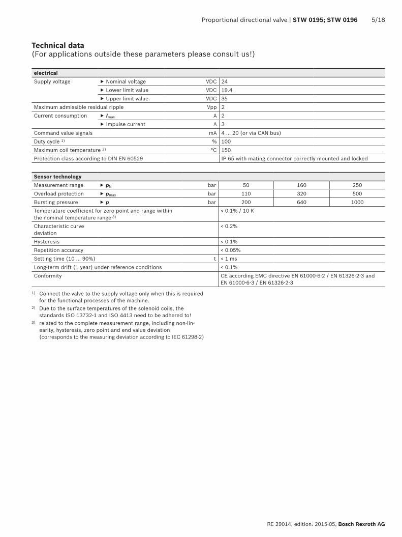
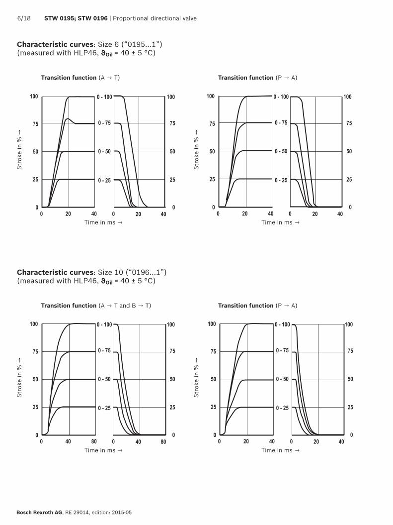
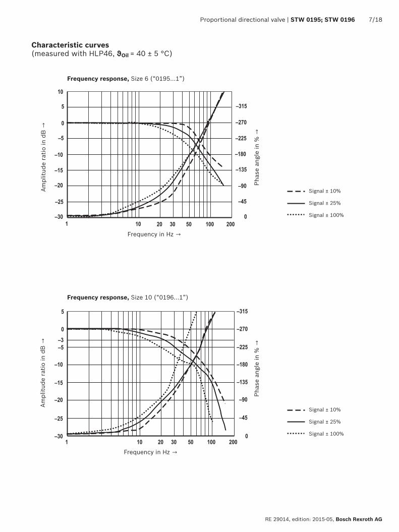
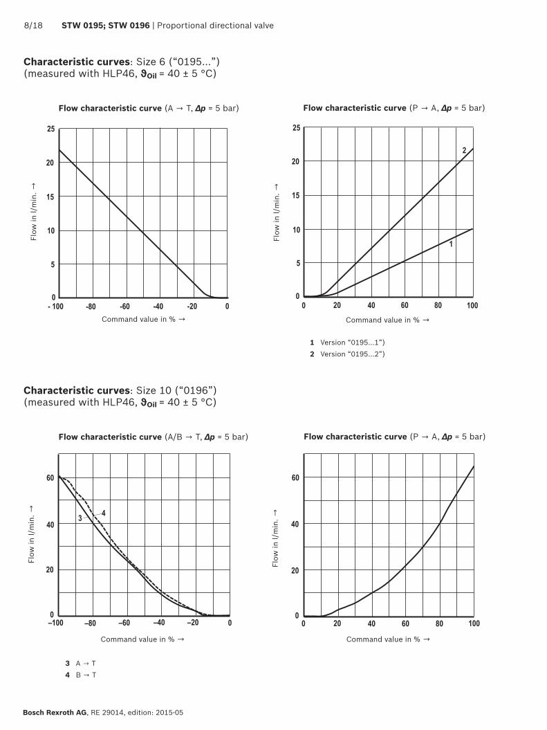
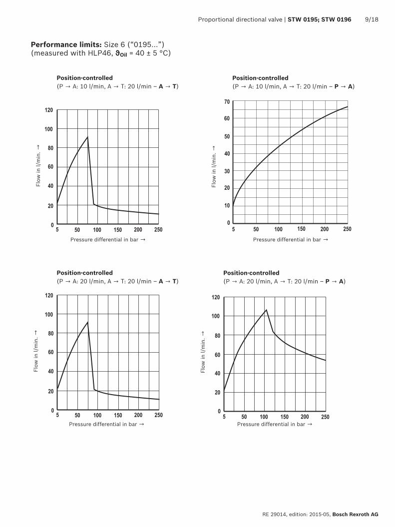
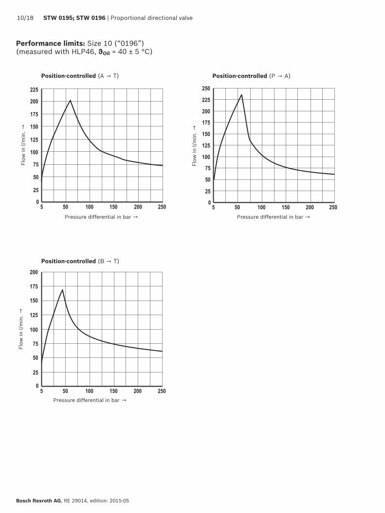
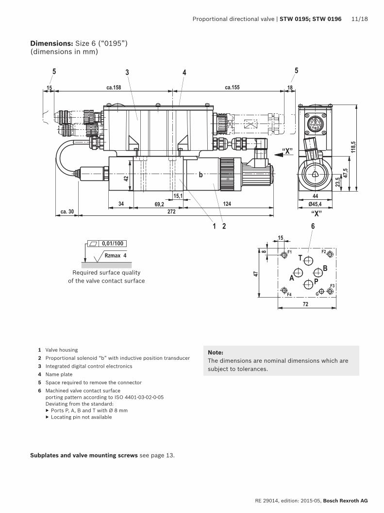
001100
Rzmax 4
13
13
13
13
Proportional directional valve | STW 0195 STW 0196 1118
RE 29014 edition 2015-05 Bosch Rexroth AG
Dimensions Size 6 (ldquo0195rdquo) (dimensions in mm)
1 Valve housing2 Proportional solenoid ldquobrdquo with inductive position transducer3 Integrated digital control electronics4 Name plate5 Space required to remove the connector6 Machined valve contact surface
porting pattern according to ISO 4401-03-02-0-05Deviating from the standard
Ports P A B and T with Oslash 8 mm Locating pin not available
Subplates and valve mounting screws see page 13
NoteThe dimensions are nominal dimensions which are subject to tolerances
Required surface quality of the valve contact surface
001100
Rzmax 4
13
1218 STW 0195 STW 0196 | Proportional directional valve
Bosch Rexroth AG RE 29014 edition 2015-05
Dimensions Size 10 (ldquo0196rdquo) (dimensions in mm)
1 Valve housing2 Proportional solenoid ldquobrdquo with inductive position transducer3 Integrated digital control electronics4 Name plate5 Space required to remove the connector6 Machined valve contact surface
Porting pattern in accordance with ISO 4401-05-04-0-05Deviating from the standardPort T1 exists additionally
Subplates and valve mounting screws see page 13
NoteThe dimensions are nominal dimensions which are subject to tolerances
Required surface quality of the valve contact surface
Proportional directional valve | STW 0195 STW 0196 1318
RE 29014 edition 2015-05 Bosch Rexroth AG
Dimensions
Valve mounting screws (separate order) Size Hexagon socket head cap screws Material number6 (ldquo0195rdquo) 4 hexagon socket head cap screws ISO 4762 - M5 x 50 - 109-flZn-240h-L
tightening torque MA = 7 Nm plusmn 10R913000064
4 hexagon socket head cap screws ISO 4762 - M5 x 50Tightening torque MA = 89 Nm plusmn 10
Not in the Rexroth delivery range
10 (ldquo0196rdquo) 4 hexagon socket head cap screws ISO 4762 - M6 x 40 - 109-flZn-240h-L tightening torque MA = 125 Nm plusmn 10
R913000058
4 hexagon socket head cap screws ISO 4762 - M6 x 40 - 109 tightening torque MA = 155 Nm plusmn 10
Not in the Rexroth delivery range
NoticeThe tightening torque of the hexagon socket head cap screws refers to the maximum operating pressure
Subplates (separate order) Size Data sheet Material number
6 (ldquo0195rdquo) 45052 ndash10 (ldquo0196rdquo) 45054 ndash
1418 STW 0195 STW 0196 | Proportional directional valve
Bosch Rexroth AG RE 29014 edition 2015-05
1) Litz wire colors of the connection line for mating connector with cable set (see accessories page 17)
Electrical connections assignment
X1
Pin Core marking 1)
Interface A6 allocation Allocation Interface F6
1 1 24 VDC (u(t) = 194 V hellip 35 V) Imax = 17 A (for output stage)2 2 0 V ≙ load zero reference for pins 1 and 93 white enable input 9 35 V ≙ enable on4 yellow plusmn 10 V command value Q Re gt 50 kΩ 4 hellip 20 mA command value Q Re = 100 Ω5 green Reference for command values Q and p6 purple plusmn 10 V actual value Q 4 20 mA actual value Q (load resistance max 300 Ω)7 pink 0 10 V command value p Re gt 50 kΩ 4 20 mA command value p Re = 100 kΩ8 red 0 hellip 10 V actual value p 4 20 mA actual value p (load resistance max 300 Ω)9 brown Control voltage level as pin 1 Imax = 03 A (for signal part and bus)
10 black 0 V reference potential for pins 3 6 8 and 11 (connected with pin 2 in valve)11 blue Error output 24 V (194 V hellip 35 V) 200 mA max loadPE green-yellow Connected to cooling element and valve housing
Connector pin assignment X1 11-pole + PE according to DIN EN 175201-804
Connector pin assignment X2 CAN bus (coding A) M12 x 1 5-pole pins
Transmission rate 20 hellip 1000 kBitsBus address 1 127CAN-specific settingsBaud rate and identifier must be set via the bus system
Pin Assignment1 nc2 nc3 CAN_GND4 CAN_H5 CAN_L
X2
Connector pin assignment for Profibus DP ldquoX2rdquo ldquoX3rdquo (coding B) M12 x 1 5-pole socket pins
Pin Assignment1 +5V2 RxDTxD-N (A line)3 D GND4 RxDTxD-P (B line)5 Shield
Transmission rate up to 12 MBaudBus address 1 126Setting via DIL switch
The +5V voltage of the IAC-P is available for an external terminating resistor
X2
X3
NoticeConnect shield to PE only on the supply side
NoticeWe recommend connecting the shields on both sides via the metal housings of the plug-in connectors Using connector pins will affect the shielding effect Internal screens are not required
13
13
13
13
Proportional directional valve | STW 0195 STW 0196 1518
RE 29014 edition 2015-05 Bosch Rexroth AG
Block diagram integrated control electronics
CAN bus
Command value q
Command value p
Actual value q
Actual value p
Enable
Error output
24 V load supply
24 V signal supply
GND
Output stage supply
Microcontroller
CAN controller
Controller
Actual pressure value
Output stage off
Actual value
position
Cable break
Output stage
Oscillator demodulator
Valv
e w
ith
indu
ctiv
e po
siti
onal
tra
nsdu
cer
Command value Command value 12 to 20 mA at pin 4 and reference potential at pin 5 result in flow from P rarr ACommand value 4 to 12 mA at pin 4 and reference potential at pin 5 result in flow from A rarr T
Actual value Actual value 12 to 20 mA at pin 6 and reference potential at pin 10 result in flow from P rarr AActual value 4 to 12 mA at pin 6 and reference potential at pin 10 result in flow from A rarr T
Connection line (recommended)
up to 25 m line length for pins 1 2 and PE 075 mm2 otherwise 025 mm2
up to 50 m line length for pins 1 2 and PE 100 mm2
External diameter see sketch of mating connector
Reference for pins 4 7Reference for pins 3 6 8 11
Protective earth-ing conductor
Electrical connections assignment
Alternatively
Profibus Profibus controller
1618 STW 0195 STW 0196 | Proportional directional valve
Bosch Rexroth AG RE 29014 edition 2015-05
Accessories (separate order)
3
1
2
The following is required for the parameter-ization via PC
CANopen Profibus DP
1 interface converter (USB) VT-ZKO-USBCA-1-1XV00Material no R901071963
VT-ZKO-USBP-1-1XV00Material no R901071962
2 Commissioning software WINPEDDownload from wwwboschrexrothdeIAC
3 Connection cable 3 m D-Sub M12 coding AMaterial no R900751271
D-Sub M12 coding BMaterial no R901078053
Proportional directional valve | STW 0195 STW 0196 1718
RE 29014 edition 2015-05 Bosch Rexroth AG
Accessories (separate order)
Port X1 Mating connector for X1 Dimensions Material numberMating connector according to DIN EN 17520-804 (11-pole + PE) plastic variant
Without cable (assembly kit) R900884671With cable set 2 x 5 m 12-pole R900032356With cable set 2 x 20 m 12-pole R900860399
CAN bus (A coding)Plug-in connector for X2 View dimensions Material numberRound connector processable 5-pole M12 x 1Straight mating connector in metal design
(line diameter 6 8 mm)
R901076910
Profibus (B coding)Plug-in connector for X2 and X3 View dimensions Material numberX2Round connector processable 5-pole M12 x 1Straight mating connector in metal design
Oslash19
6
ca 61
15
4
32
(line diameter 6 8 mm)
R901075545
X3Round connector processable 5-pole M12 x 1Straight mating connector in metal design
(line diameter 6 8 mm)
R901075550
Protective cap Protective cap M12 Version Material number
R901075563
Bosch Rexroth AG RE 29014 edition 2015-05
1818 STW 0195 STW 0196 | Proportional directional valve
Bosch Rexroth AG HydraulicsZum Eisengieszliger 197816 Lohr am Main Germany Phone +49 (0) 93 52thinspthinsp18-0 documentationboschrexrothde wwwboschrexrothde
copy This document as well as the data specifications and other information set forth in it are the exclusive property of Bosch Rexroth AG It may not be reproduced or given to third parties without the consent of Bosch Rexroth AGThe data specified only serve to describe the product It cannot be used to derive statements concerning a certain condition or suitability for a certain application This information also does not release the user from the obligation of own judgment and verification It must be remembered that our products are subject to a natural process of wear and aging
Project planning and maintenance instructions
Connect the valve to the supply voltage only when this is required for the functional processes of the machine
Do not use electrical signals provided via control elec-tronics (eg ldquoNo errorrdquo signal) for switching safety-rele-vant machine functions (see also EN ISO 13849 ldquoSafety of machinery ndash safety-related parts of control systemsrdquo)
If electro-magnetic interference must be expected take appropriate measures to ensure the function (depend-ing on the application eg shielding filtration)
The devices have been tested in the plant and are sup-plied with default settings
Only complete units can be repaired Repaired devices are returned with default settings User-specific settings are not maintained The machine end-user will have to retransfer the corresponding user parameters
Further information
Subplates Data sheets 45052 45054 Hydraulic fluids on mineral oil basis Data sheet 90220 Environmentally compatible hydraulic fluids Data sheet 90221 Flame-resistant water-free hydraulic fluids Data sheet 90222 Hydraulic valves for industrial applications Data sheet 07600-B Assembly commissioning and maintenance of hydraulic systems Data sheet 07900 CANopen protocol for IFB-P and IAC-P valves protocol description Data sheet 29015-01-Z Profibus protocol for IFB and IAC-P valves protocol description Data sheet 29015-02-Z Proportional directional valves with field bus interface with and without inte-
grated axis controller (IAC-P and IFB-P) operating instructionsData sheet 29015-B
Commissioning software and documentation on the Internet wwwboschrexrothcomIAC Selection of the filters wwwboschrexrothcomfilter
Proportional directional valve | STW 0195 STW 0196 1918
RE 29014 edition 2015-05 Bosch Rexroth AG
Bosch Rexroth AG HydraulicsZum Eisengieszliger 197816 Lohr am Main Germany Phone +49 (0) 93 52thinspthinsp18-0 documentationboschrexrothde wwwboschrexrothde
copy This document as well as the data specifications and other information set forth in it are the exclusive property of Bosch Rexroth AG It may not be reproduced or given to third parties without the consent of Bosch Rexroth AGThe data specified only serve to describe the product It cannot be used to derive statements concerning a certain condition or suitability for a certain application This information also does not release the user from the obligation of own judgment and verification It must be remembered that our products are subject to a natural process of wear and aging
Notes
Bosch Rexroth AG RE 29014 edition 2015-05
2018 STW 0195 STW 0196 | Proportional directional valve
Bosch Rexroth AG HydraulicsZum Eisengieszliger 197816 Lohr am Main Germany Phone +49 (0) 93 52thinspthinsp18-0 documentationboschrexrothde wwwboschrexrothde
copy This document as well as the data specifications and other information set forth in it are the exclusive property of Bosch Rexroth AG It may not be reproduced or given to third parties without the consent of Bosch Rexroth AGThe data specified only serve to describe the product It cannot be used to derive statements concerning a certain condition or suitability for a certain application This information also does not release the user from the obligation of own judgment and verification It must be remembered that our products are subject to a natural process of wear and aging
Notes
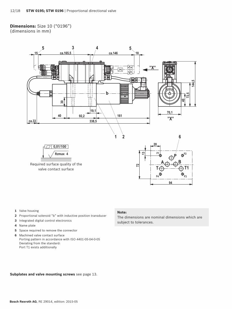
001100
Rzmax 4
13
1218 STW 0195 STW 0196 | Proportional directional valve
Bosch Rexroth AG RE 29014 edition 2015-05
Dimensions Size 10 (ldquo0196rdquo) (dimensions in mm)
1 Valve housing2 Proportional solenoid ldquobrdquo with inductive position transducer3 Integrated digital control electronics4 Name plate5 Space required to remove the connector6 Machined valve contact surface
Porting pattern in accordance with ISO 4401-05-04-0-05Deviating from the standardPort T1 exists additionally
Subplates and valve mounting screws see page 13
NoteThe dimensions are nominal dimensions which are subject to tolerances
Required surface quality of the valve contact surface
Proportional directional valve | STW 0195 STW 0196 1318
RE 29014 edition 2015-05 Bosch Rexroth AG
Dimensions
Valve mounting screws (separate order) Size Hexagon socket head cap screws Material number6 (ldquo0195rdquo) 4 hexagon socket head cap screws ISO 4762 - M5 x 50 - 109-flZn-240h-L
tightening torque MA = 7 Nm plusmn 10R913000064
4 hexagon socket head cap screws ISO 4762 - M5 x 50Tightening torque MA = 89 Nm plusmn 10
Not in the Rexroth delivery range
10 (ldquo0196rdquo) 4 hexagon socket head cap screws ISO 4762 - M6 x 40 - 109-flZn-240h-L tightening torque MA = 125 Nm plusmn 10
R913000058
4 hexagon socket head cap screws ISO 4762 - M6 x 40 - 109 tightening torque MA = 155 Nm plusmn 10
Not in the Rexroth delivery range
NoticeThe tightening torque of the hexagon socket head cap screws refers to the maximum operating pressure
Subplates (separate order) Size Data sheet Material number
6 (ldquo0195rdquo) 45052 ndash10 (ldquo0196rdquo) 45054 ndash
1418 STW 0195 STW 0196 | Proportional directional valve
Bosch Rexroth AG RE 29014 edition 2015-05
1) Litz wire colors of the connection line for mating connector with cable set (see accessories page 17)
Electrical connections assignment
X1
Pin Core marking 1)
Interface A6 allocation Allocation Interface F6
1 1 24 VDC (u(t) = 194 V hellip 35 V) Imax = 17 A (for output stage)2 2 0 V ≙ load zero reference for pins 1 and 93 white enable input 9 35 V ≙ enable on4 yellow plusmn 10 V command value Q Re gt 50 kΩ 4 hellip 20 mA command value Q Re = 100 Ω5 green Reference for command values Q and p6 purple plusmn 10 V actual value Q 4 20 mA actual value Q (load resistance max 300 Ω)7 pink 0 10 V command value p Re gt 50 kΩ 4 20 mA command value p Re = 100 kΩ8 red 0 hellip 10 V actual value p 4 20 mA actual value p (load resistance max 300 Ω)9 brown Control voltage level as pin 1 Imax = 03 A (for signal part and bus)
10 black 0 V reference potential for pins 3 6 8 and 11 (connected with pin 2 in valve)11 blue Error output 24 V (194 V hellip 35 V) 200 mA max loadPE green-yellow Connected to cooling element and valve housing
Connector pin assignment X1 11-pole + PE according to DIN EN 175201-804
Connector pin assignment X2 CAN bus (coding A) M12 x 1 5-pole pins
Transmission rate 20 hellip 1000 kBitsBus address 1 127CAN-specific settingsBaud rate and identifier must be set via the bus system
Pin Assignment1 nc2 nc3 CAN_GND4 CAN_H5 CAN_L
X2
Connector pin assignment for Profibus DP ldquoX2rdquo ldquoX3rdquo (coding B) M12 x 1 5-pole socket pins
Pin Assignment1 +5V2 RxDTxD-N (A line)3 D GND4 RxDTxD-P (B line)5 Shield
Transmission rate up to 12 MBaudBus address 1 126Setting via DIL switch
The +5V voltage of the IAC-P is available for an external terminating resistor
X2
X3
NoticeConnect shield to PE only on the supply side
NoticeWe recommend connecting the shields on both sides via the metal housings of the plug-in connectors Using connector pins will affect the shielding effect Internal screens are not required
13
13
13
13
Proportional directional valve | STW 0195 STW 0196 1518
RE 29014 edition 2015-05 Bosch Rexroth AG
Block diagram integrated control electronics
CAN bus
Command value q
Command value p
Actual value q
Actual value p
Enable
Error output
24 V load supply
24 V signal supply
GND
Output stage supply
Microcontroller
CAN controller
Controller
Actual pressure value
Output stage off
Actual value
position
Cable break
Output stage
Oscillator demodulator
Valv
e w
ith
indu
ctiv
e po
siti
onal
tra
nsdu
cer
Command value Command value 12 to 20 mA at pin 4 and reference potential at pin 5 result in flow from P rarr ACommand value 4 to 12 mA at pin 4 and reference potential at pin 5 result in flow from A rarr T
Actual value Actual value 12 to 20 mA at pin 6 and reference potential at pin 10 result in flow from P rarr AActual value 4 to 12 mA at pin 6 and reference potential at pin 10 result in flow from A rarr T
Connection line (recommended)
up to 25 m line length for pins 1 2 and PE 075 mm2 otherwise 025 mm2
up to 50 m line length for pins 1 2 and PE 100 mm2
External diameter see sketch of mating connector
Reference for pins 4 7Reference for pins 3 6 8 11
Protective earth-ing conductor
Electrical connections assignment
Alternatively
Profibus Profibus controller
1618 STW 0195 STW 0196 | Proportional directional valve
Bosch Rexroth AG RE 29014 edition 2015-05
Accessories (separate order)
3
1
2
The following is required for the parameter-ization via PC
CANopen Profibus DP
1 interface converter (USB) VT-ZKO-USBCA-1-1XV00Material no R901071963
VT-ZKO-USBP-1-1XV00Material no R901071962
2 Commissioning software WINPEDDownload from wwwboschrexrothdeIAC
3 Connection cable 3 m D-Sub M12 coding AMaterial no R900751271
D-Sub M12 coding BMaterial no R901078053
Proportional directional valve | STW 0195 STW 0196 1718
RE 29014 edition 2015-05 Bosch Rexroth AG
Accessories (separate order)
Port X1 Mating connector for X1 Dimensions Material numberMating connector according to DIN EN 17520-804 (11-pole + PE) plastic variant
Without cable (assembly kit) R900884671With cable set 2 x 5 m 12-pole R900032356With cable set 2 x 20 m 12-pole R900860399
CAN bus (A coding)Plug-in connector for X2 View dimensions Material numberRound connector processable 5-pole M12 x 1Straight mating connector in metal design
(line diameter 6 8 mm)
R901076910
Profibus (B coding)Plug-in connector for X2 and X3 View dimensions Material numberX2Round connector processable 5-pole M12 x 1Straight mating connector in metal design
Oslash19
6
ca 61
15
4
32
(line diameter 6 8 mm)
R901075545
X3Round connector processable 5-pole M12 x 1Straight mating connector in metal design
(line diameter 6 8 mm)
R901075550
Protective cap Protective cap M12 Version Material number
R901075563
Bosch Rexroth AG RE 29014 edition 2015-05
1818 STW 0195 STW 0196 | Proportional directional valve
Bosch Rexroth AG HydraulicsZum Eisengieszliger 197816 Lohr am Main Germany Phone +49 (0) 93 52thinspthinsp18-0 documentationboschrexrothde wwwboschrexrothde
copy This document as well as the data specifications and other information set forth in it are the exclusive property of Bosch Rexroth AG It may not be reproduced or given to third parties without the consent of Bosch Rexroth AGThe data specified only serve to describe the product It cannot be used to derive statements concerning a certain condition or suitability for a certain application This information also does not release the user from the obligation of own judgment and verification It must be remembered that our products are subject to a natural process of wear and aging
Project planning and maintenance instructions
Connect the valve to the supply voltage only when this is required for the functional processes of the machine
Do not use electrical signals provided via control elec-tronics (eg ldquoNo errorrdquo signal) for switching safety-rele-vant machine functions (see also EN ISO 13849 ldquoSafety of machinery ndash safety-related parts of control systemsrdquo)
If electro-magnetic interference must be expected take appropriate measures to ensure the function (depend-ing on the application eg shielding filtration)
The devices have been tested in the plant and are sup-plied with default settings
Only complete units can be repaired Repaired devices are returned with default settings User-specific settings are not maintained The machine end-user will have to retransfer the corresponding user parameters
Further information
Subplates Data sheets 45052 45054 Hydraulic fluids on mineral oil basis Data sheet 90220 Environmentally compatible hydraulic fluids Data sheet 90221 Flame-resistant water-free hydraulic fluids Data sheet 90222 Hydraulic valves for industrial applications Data sheet 07600-B Assembly commissioning and maintenance of hydraulic systems Data sheet 07900 CANopen protocol for IFB-P and IAC-P valves protocol description Data sheet 29015-01-Z Profibus protocol for IFB and IAC-P valves protocol description Data sheet 29015-02-Z Proportional directional valves with field bus interface with and without inte-
grated axis controller (IAC-P and IFB-P) operating instructionsData sheet 29015-B
Commissioning software and documentation on the Internet wwwboschrexrothcomIAC Selection of the filters wwwboschrexrothcomfilter
Proportional directional valve | STW 0195 STW 0196 1918
RE 29014 edition 2015-05 Bosch Rexroth AG
Bosch Rexroth AG HydraulicsZum Eisengieszliger 197816 Lohr am Main Germany Phone +49 (0) 93 52thinspthinsp18-0 documentationboschrexrothde wwwboschrexrothde
copy This document as well as the data specifications and other information set forth in it are the exclusive property of Bosch Rexroth AG It may not be reproduced or given to third parties without the consent of Bosch Rexroth AGThe data specified only serve to describe the product It cannot be used to derive statements concerning a certain condition or suitability for a certain application This information also does not release the user from the obligation of own judgment and verification It must be remembered that our products are subject to a natural process of wear and aging
Notes
Bosch Rexroth AG RE 29014 edition 2015-05
2018 STW 0195 STW 0196 | Proportional directional valve
Bosch Rexroth AG HydraulicsZum Eisengieszliger 197816 Lohr am Main Germany Phone +49 (0) 93 52thinspthinsp18-0 documentationboschrexrothde wwwboschrexrothde
copy This document as well as the data specifications and other information set forth in it are the exclusive property of Bosch Rexroth AG It may not be reproduced or given to third parties without the consent of Bosch Rexroth AGThe data specified only serve to describe the product It cannot be used to derive statements concerning a certain condition or suitability for a certain application This information also does not release the user from the obligation of own judgment and verification It must be remembered that our products are subject to a natural process of wear and aging
Notes
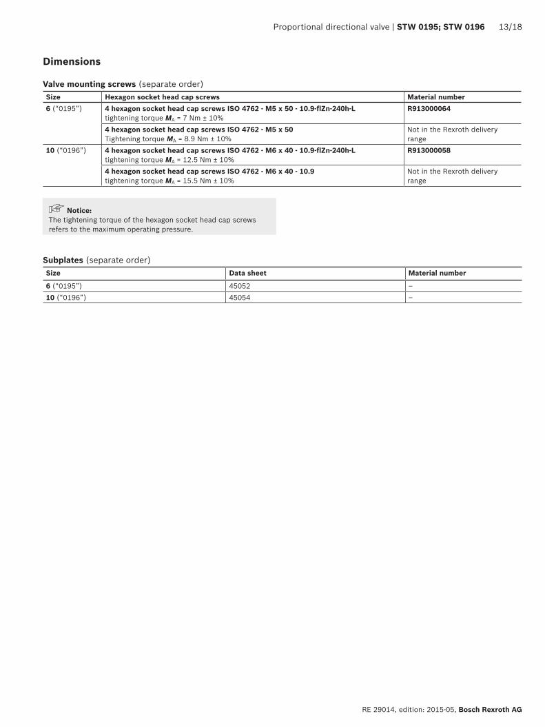
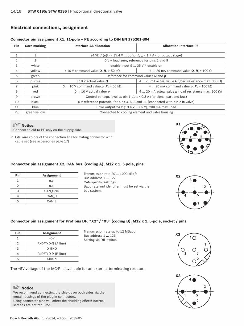
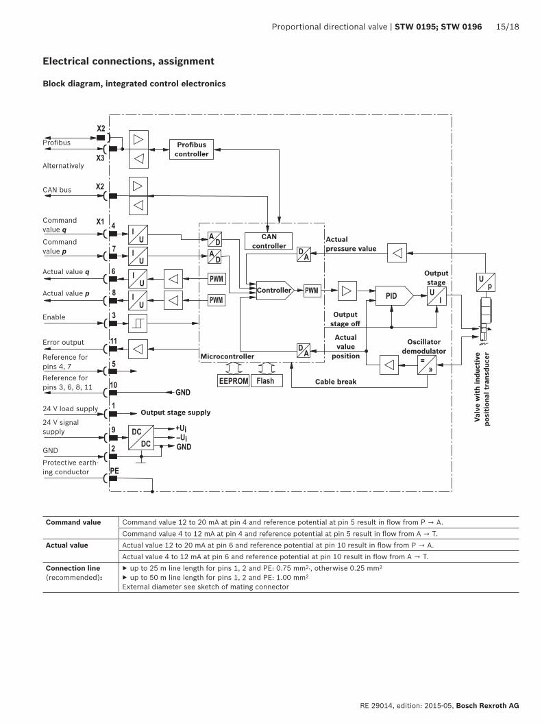
13
13
13
13
Proportional directional valve | STW 0195 STW 0196 1518
RE 29014 edition 2015-05 Bosch Rexroth AG
Block diagram integrated control electronics
CAN bus
Command value q
Command value p
Actual value q
Actual value p
Enable
Error output
24 V load supply
24 V signal supply
GND
Output stage supply
Microcontroller
CAN controller
Controller
Actual pressure value
Output stage off
Actual value
position
Cable break
Output stage
Oscillator demodulator
Valv
e w
ith
indu
ctiv
e po
siti
onal
tra
nsdu
cer
Command value Command value 12 to 20 mA at pin 4 and reference potential at pin 5 result in flow from P rarr ACommand value 4 to 12 mA at pin 4 and reference potential at pin 5 result in flow from A rarr T
Actual value Actual value 12 to 20 mA at pin 6 and reference potential at pin 10 result in flow from P rarr AActual value 4 to 12 mA at pin 6 and reference potential at pin 10 result in flow from A rarr T
Connection line (recommended)
up to 25 m line length for pins 1 2 and PE 075 mm2 otherwise 025 mm2
up to 50 m line length for pins 1 2 and PE 100 mm2
External diameter see sketch of mating connector
Reference for pins 4 7Reference for pins 3 6 8 11
Protective earth-ing conductor
Electrical connections assignment
Alternatively
Profibus Profibus controller
1618 STW 0195 STW 0196 | Proportional directional valve
Bosch Rexroth AG RE 29014 edition 2015-05
Accessories (separate order)
3
1
2
The following is required for the parameter-ization via PC
CANopen Profibus DP
1 interface converter (USB) VT-ZKO-USBCA-1-1XV00Material no R901071963
VT-ZKO-USBP-1-1XV00Material no R901071962
2 Commissioning software WINPEDDownload from wwwboschrexrothdeIAC
3 Connection cable 3 m D-Sub M12 coding AMaterial no R900751271
D-Sub M12 coding BMaterial no R901078053
Proportional directional valve | STW 0195 STW 0196 1718
RE 29014 edition 2015-05 Bosch Rexroth AG
Accessories (separate order)
Port X1 Mating connector for X1 Dimensions Material numberMating connector according to DIN EN 17520-804 (11-pole + PE) plastic variant
Without cable (assembly kit) R900884671With cable set 2 x 5 m 12-pole R900032356With cable set 2 x 20 m 12-pole R900860399
CAN bus (A coding)Plug-in connector for X2 View dimensions Material numberRound connector processable 5-pole M12 x 1Straight mating connector in metal design
(line diameter 6 8 mm)
R901076910
Profibus (B coding)Plug-in connector for X2 and X3 View dimensions Material numberX2Round connector processable 5-pole M12 x 1Straight mating connector in metal design
Oslash19
6
ca 61
15
4
32
(line diameter 6 8 mm)
R901075545
X3Round connector processable 5-pole M12 x 1Straight mating connector in metal design
(line diameter 6 8 mm)
R901075550
Protective cap Protective cap M12 Version Material number
R901075563
Bosch Rexroth AG RE 29014 edition 2015-05
1818 STW 0195 STW 0196 | Proportional directional valve
Bosch Rexroth AG HydraulicsZum Eisengieszliger 197816 Lohr am Main Germany Phone +49 (0) 93 52thinspthinsp18-0 documentationboschrexrothde wwwboschrexrothde
copy This document as well as the data specifications and other information set forth in it are the exclusive property of Bosch Rexroth AG It may not be reproduced or given to third parties without the consent of Bosch Rexroth AGThe data specified only serve to describe the product It cannot be used to derive statements concerning a certain condition or suitability for a certain application This information also does not release the user from the obligation of own judgment and verification It must be remembered that our products are subject to a natural process of wear and aging
Project planning and maintenance instructions
Connect the valve to the supply voltage only when this is required for the functional processes of the machine
Do not use electrical signals provided via control elec-tronics (eg ldquoNo errorrdquo signal) for switching safety-rele-vant machine functions (see also EN ISO 13849 ldquoSafety of machinery ndash safety-related parts of control systemsrdquo)
If electro-magnetic interference must be expected take appropriate measures to ensure the function (depend-ing on the application eg shielding filtration)
The devices have been tested in the plant and are sup-plied with default settings
Only complete units can be repaired Repaired devices are returned with default settings User-specific settings are not maintained The machine end-user will have to retransfer the corresponding user parameters
Further information
Subplates Data sheets 45052 45054 Hydraulic fluids on mineral oil basis Data sheet 90220 Environmentally compatible hydraulic fluids Data sheet 90221 Flame-resistant water-free hydraulic fluids Data sheet 90222 Hydraulic valves for industrial applications Data sheet 07600-B Assembly commissioning and maintenance of hydraulic systems Data sheet 07900 CANopen protocol for IFB-P and IAC-P valves protocol description Data sheet 29015-01-Z Profibus protocol for IFB and IAC-P valves protocol description Data sheet 29015-02-Z Proportional directional valves with field bus interface with and without inte-
grated axis controller (IAC-P and IFB-P) operating instructionsData sheet 29015-B
Commissioning software and documentation on the Internet wwwboschrexrothcomIAC Selection of the filters wwwboschrexrothcomfilter
Proportional directional valve | STW 0195 STW 0196 1918
RE 29014 edition 2015-05 Bosch Rexroth AG
Bosch Rexroth AG HydraulicsZum Eisengieszliger 197816 Lohr am Main Germany Phone +49 (0) 93 52thinspthinsp18-0 documentationboschrexrothde wwwboschrexrothde
copy This document as well as the data specifications and other information set forth in it are the exclusive property of Bosch Rexroth AG It may not be reproduced or given to third parties without the consent of Bosch Rexroth AGThe data specified only serve to describe the product It cannot be used to derive statements concerning a certain condition or suitability for a certain application This information also does not release the user from the obligation of own judgment and verification It must be remembered that our products are subject to a natural process of wear and aging
Notes
Bosch Rexroth AG RE 29014 edition 2015-05
2018 STW 0195 STW 0196 | Proportional directional valve
Bosch Rexroth AG HydraulicsZum Eisengieszliger 197816 Lohr am Main Germany Phone +49 (0) 93 52thinspthinsp18-0 documentationboschrexrothde wwwboschrexrothde
copy This document as well as the data specifications and other information set forth in it are the exclusive property of Bosch Rexroth AG It may not be reproduced or given to third parties without the consent of Bosch Rexroth AGThe data specified only serve to describe the product It cannot be used to derive statements concerning a certain condition or suitability for a certain application This information also does not release the user from the obligation of own judgment and verification It must be remembered that our products are subject to a natural process of wear and aging
Notes
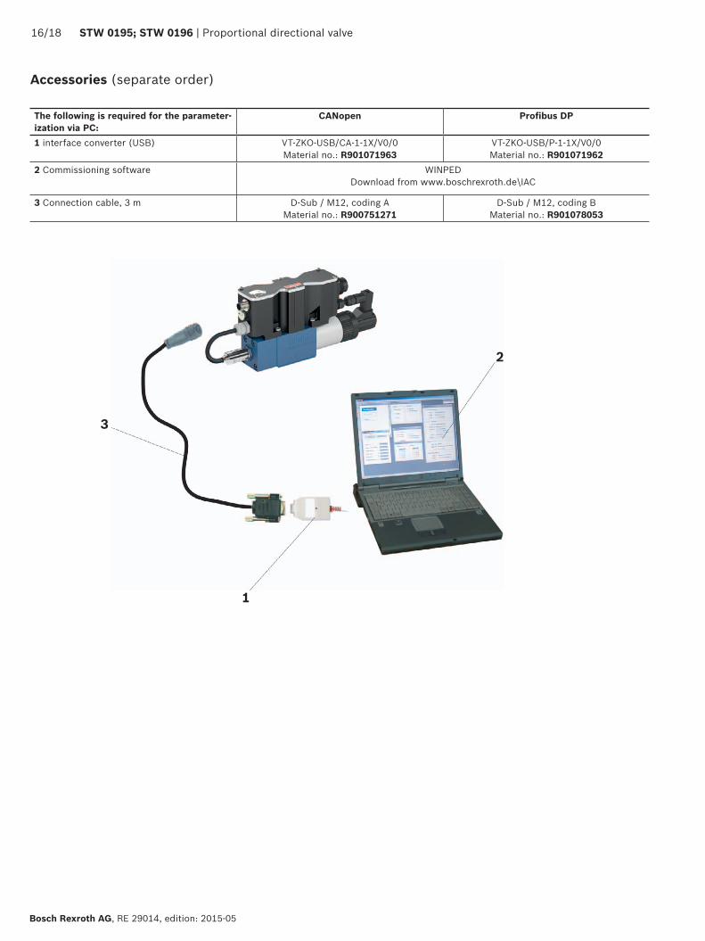
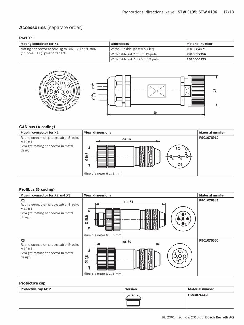
Bosch Rexroth AG RE 29014 edition 2015-05
1818 STW 0195 STW 0196 | Proportional directional valve
Bosch Rexroth AG HydraulicsZum Eisengieszliger 197816 Lohr am Main Germany Phone +49 (0) 93 52thinspthinsp18-0 documentationboschrexrothde wwwboschrexrothde
copy This document as well as the data specifications and other information set forth in it are the exclusive property of Bosch Rexroth AG It may not be reproduced or given to third parties without the consent of Bosch Rexroth AGThe data specified only serve to describe the product It cannot be used to derive statements concerning a certain condition or suitability for a certain application This information also does not release the user from the obligation of own judgment and verification It must be remembered that our products are subject to a natural process of wear and aging
Project planning and maintenance instructions
Connect the valve to the supply voltage only when this is required for the functional processes of the machine
Do not use electrical signals provided via control elec-tronics (eg ldquoNo errorrdquo signal) for switching safety-rele-vant machine functions (see also EN ISO 13849 ldquoSafety of machinery ndash safety-related parts of control systemsrdquo)
If electro-magnetic interference must be expected take appropriate measures to ensure the function (depend-ing on the application eg shielding filtration)
The devices have been tested in the plant and are sup-plied with default settings
Only complete units can be repaired Repaired devices are returned with default settings User-specific settings are not maintained The machine end-user will have to retransfer the corresponding user parameters
Further information
Subplates Data sheets 45052 45054 Hydraulic fluids on mineral oil basis Data sheet 90220 Environmentally compatible hydraulic fluids Data sheet 90221 Flame-resistant water-free hydraulic fluids Data sheet 90222 Hydraulic valves for industrial applications Data sheet 07600-B Assembly commissioning and maintenance of hydraulic systems Data sheet 07900 CANopen protocol for IFB-P and IAC-P valves protocol description Data sheet 29015-01-Z Profibus protocol for IFB and IAC-P valves protocol description Data sheet 29015-02-Z Proportional directional valves with field bus interface with and without inte-
grated axis controller (IAC-P and IFB-P) operating instructionsData sheet 29015-B
Commissioning software and documentation on the Internet wwwboschrexrothcomIAC Selection of the filters wwwboschrexrothcomfilter
Proportional directional valve | STW 0195 STW 0196 1918
RE 29014 edition 2015-05 Bosch Rexroth AG
Bosch Rexroth AG HydraulicsZum Eisengieszliger 197816 Lohr am Main Germany Phone +49 (0) 93 52thinspthinsp18-0 documentationboschrexrothde wwwboschrexrothde
copy This document as well as the data specifications and other information set forth in it are the exclusive property of Bosch Rexroth AG It may not be reproduced or given to third parties without the consent of Bosch Rexroth AGThe data specified only serve to describe the product It cannot be used to derive statements concerning a certain condition or suitability for a certain application This information also does not release the user from the obligation of own judgment and verification It must be remembered that our products are subject to a natural process of wear and aging
Notes
Bosch Rexroth AG RE 29014 edition 2015-05
2018 STW 0195 STW 0196 | Proportional directional valve
Bosch Rexroth AG HydraulicsZum Eisengieszliger 197816 Lohr am Main Germany Phone +49 (0) 93 52thinspthinsp18-0 documentationboschrexrothde wwwboschrexrothde
copy This document as well as the data specifications and other information set forth in it are the exclusive property of Bosch Rexroth AG It may not be reproduced or given to third parties without the consent of Bosch Rexroth AGThe data specified only serve to describe the product It cannot be used to derive statements concerning a certain condition or suitability for a certain application This information also does not release the user from the obligation of own judgment and verification It must be remembered that our products are subject to a natural process of wear and aging
Notes