Embed Size (px)
Citation preview
materials
Article
Property Comparison of Alkali-Activated CarbonSteel Slag (CSS) and Stainless Steel Slag (SSS) andRole of Blast Furnace Slag (BFS)Chemical Composition
Jinyan Liu 1,2,* , Cheng Yi 1, Hongguang Zhu 1 and Hongqiang Ma 1,3
1 School of Mechanics and Civil Engineering, China University of Mining & Technology (Beijing),Beijing 100083, China
2 Department of Civil Engineering, Shanxi University, Taiyuan 030006, China3 Department of Civil and Natural Resources Engineering, University of Canterbury,
Christchurch 8041, New Zealand* Correspondence: [email protected]
Received: 23 August 2019; Accepted: 9 October 2019; Published: 11 October 2019�����������������
Abstract: In order to compare the properties of alkali-activated carbon steel slag (CSS) and stainlesssteel slag (SSS), the effects of sodium hydroxide/sodium silicate solution mass ratio (NH/NS),liquid/solid ratio and blast furnace slag (BFS) dosage on the compressive strength, hydrationproducts and hydration degree of CSS and SSS were studied. Furthermore, a combination of X-raydiffraction (XRD), thermo-gravimetric analysis coupled with differential thermal analysis (TGA-DTA),Fourier transform infrared spectroscopy (FT-IR) and scanning electron microscope-energy dispersivespectrometer (SEM-EDS) were used to characterize the morphology and structure of alkali-activatedCSS-BFS and SSS-BFS cementitious materials. As the results revealed, the primary hydrate ofalkali-activated CSS and SSS is C-(A)-S-H with Q2 [SiO4] units, which has a low Ca/Si ratio and includesinert phases like a CaO-FeO-MnO-MgO solid solution (RO) in CSS while cuspidine, magnesiochromiteetc. in SSS. More active C3S and β-C2S promote the alkali activation of CSS, whereas the less activeγ-C2S hinders the depolymerization of SSS. The incorporation of BFS does not change the hydrate,whose seed effect is helpful for accelerating the depolymerization and polycondensation of CSS andSSS, especially for SSS, and makes the hydrate increase significantly. Owing to the high SiO2 andAl2O3 contents of SSS, the C-(A)-S-H chain length is increased, thus facilitating the polycondensationeffect. In this study, the optimal NH/NS of CSS and SSS is NH/NS = 1:2, and the optimal liquid/solidratio is 0.29. Compared to CSS–BFS, the C-(A)-S-H gel produced by SSS–BFS has lower Ca/Si andAl/Si ratios. Unlike CSS, pure SSS is inappropriate as an alkali-activated precursor and needs to beco-activated with BFS.
Keywords: alkali activation; carbon steel slag; stainless steel slag; compressive strength;microstructural studies
1. Introduction
With the continuous development of global steel industry in recent years, bulk solid wastes likesteel slag and blast furnace slag (BFS) have tended to grow. Taking the two major types of steel slag,carbon steel slag (CSS) and stainless steel slag (SSS) [1–3], as an example, according to the latest datareleased by the World Steel Association (WSA) [4] and the International Stainless Steel Forum (ISSF) [5],the global crude steel production was 1808 million t in 2018, whereas stainless steel production was50.7 million t, showing increases by 4.6% and 5.51%, respectively, over the same period of the previous
Materials 2019, 12, 3307; doi:10.3390/ma12203307 www.mdpi.com/journal/materials
Materials 2019, 12, 3307 2 of 18
year. Assuming that the CSS accounted for 15–20% of crude steel production [6] and that 1 t of SSSwas produced for every 3 t of stainless-steel production [7], then the global productions of CSS andSSS exceeded 250 and 16 million t, respectively, in 2018. Besides, large amounts of BFS are producedannually. In 2017, the global pig iron production was 1180 million t. Assuming that the BFS productionwas 30% of pig iron production, then the BFS production could reach 390 million t. Today, BFS is widelyused in the production of cement and concrete, while steel slag receives little utilization because of itslow activity [8–10]. Currently, steel slag is used mostly for low value-added applications, includingasphalt concrete aggregates, fillers for foundation engineering, supplementary cementitious materials,etc. [1,2,11–15]. This necessitates substantial piling up of steel slag, which causes environmentalpollution, arable land occupation and resource wastage. At present, researchers in various countries arecommitted to seeking effective ways to enhance steel slag and increase the utilization rate of steel slag.
The methods of steel slag activation mainly include thermal activation [16–18], mechanicalactivation [19,20], chemical activation [9,12,18,21] and steel slag reconstruction [22,23], of which alkaliactivation is undoubtedly the current hot topic. Alkali activated materials (AAMs) are a class ofcementitious materials formed by reacting pozzolanic or latently hydraulic materials like fly ash (FA),blast furnace slag (BFS) and metakaolin with alkaline activators. They have received widespreadscholarly attention owing to their prominent physical properties such as high strength, high corrosionresistance, fire resistance, hazardous waste sealability, as well as the advantage of efficient industrialresidue utilization [12,24–27]. On the other hand, alkali-activated materials have large drying shrinkageand poor toughness, which can cause cracking of paste, mortar or concrete, thus restricting theirdevelopment [28–31].
Clearly, the use of steel slag as the precursor for preparing the alkali-activated steel slag-basedcementitious material not only can improve the utilization rate of steel slag, but can also lower thecement content, which is favorable for energy conservation and environmental protection. Hu etal. [32] prepared geopolymer repair material through alkaline activation by adding 20% CSS intometakaolin and found that the material possessed a good compressive strength and an apparentlybetter bonding strength with old concrete than the cement-based repair materials. Wang and Yan [10]observed that the BOF slag activating effect of NaOH was evident in the earlier hydration stage, whichweakened in the later stage. The hydration products of BOF slag mainly included C-S-H containing Al,Mg, Fe, as well as Ca (OH)2. Gonzalez et al.’s [23] high-temperature reconstruction study based onSi, Al material addition into BOF slag revealed that low modulus alkali was enough to stimulate theactivity of modified BOF slag, and that the hydration product was amorphous C (F,N)-A-S-H. Peng etal. [33] verified that the alkali activation could not fully stimulate the activity of pure CSS, while acombination of CSS and BFS was conducive to the development of cementitious system hydration.Thermal plus alkali activation was performed by Salman et al. [18] to endow the stainless-steel refiningslag with cementing activity. Their results demonstrated that the activation process was accompaniedby the decline of C2S and bredigite, and the final hydration product was C-S-H. Shi [9] showed thatwater glass can stimulate the cementitious activity of ladle slag at room temperature by adding BFS.The fabrication of steel slag and BFS-based cement-free cementitious materials by Cui et al. [34] andTsai et al. [35] suggested that CSS and BFS could mutually facilitate hydration.
Overall, as a high-calcium precursor, the alkali-activated steel slag is less studied than thealkali-activated BFS system. The complex activation via multiple modes, or the combination of steelslag with other solid waste materials as the precursor for alkali activation are the major researchdirections [33,36,37]. On the other hand, the majority of existing works have focused on CSS. Indeed,the differences in the chemical composition, mineral phase and crystal structure among steel slag typeslead to varying alkali activation properties. Further revelation is needed as to the alkali excitationmechanism of SSS. In view of the wide application of BFS in geopolymers, and the precedent ofcombining CSS with BFS as an alkali-activation precursor [9,33], this paper comparatively investigatesthe effects of sodium hydroxide/sodium silicate (NH:NS) solution mass ratio, liquid/solid ratio andBFS dosage on the polymer strength, non-evaporable water content, hydrates and the microstructure
Materials 2019, 12, 3307 3 of 18
of CSS and SSS by using a mixture of NaOH and NS as an activator. While contributing to the furtherunderstanding of CSS and SSS as precursors for alkali activation, this also facilitates a deeper probinginto the mechanism of BFS powder modification.
2. Materials and Methods
2.1. Materials
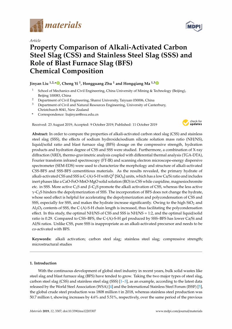
The CSS and SSS were from Taiyuan Iron & Steel (Group) Co., Ltd. in Shanxi, China. The P.O42.5 cement conforming to Chinese National Standard GB175-2007 were from Jigang Cement Co.,Ltd. in Wenshui, Shanxi, China. In Figure 1, the particle size distributions of the tailings obtainedthrough crushing, grinding, magnetic separation and sieving are presented. The median particle sized50 values of CSS, SSS and BFS were 21.141 µm, 18.220 µm and 10.529 µm, respectively. The alkaliactivators used were 96% analytical grade NaOH and sodium silicate solution having a modulus of3.22 (26.5% SiO2, 8.5% Na2O, 65% H2O).
Materials 2019, 12, x FOR PEER REVIEW 3 of 18
ratio, liquid/solid ratio and BFS dosage on the polymer strength, non-evaporable water content, hydrates and the microstructure of CSS and SSS by using a mixture of NaOH and NS as an activator. While contributing to the further understanding of CSS and SSS as precursors for alkali activation, this also facilitates a deeper probing into the mechanism of BFS powder modification.
2. Materials and Methods
2.1. Materials
The CSS and SSS were from Taiyuan Iron & Steel (Group) Co., Ltd. in Shanxi. China. The P.O 42.5 cement conforming to Chinese National Standard GB175-2007 were from Jigang Cement Co., Ltd. in Wenshui, Shanxi, China. In Figure 1, the particle size distributions of the tailings obtained through crushing, grinding, magnetic separation and sieving are presented. The median particle size d50 values of CSS, SSS and BFS were 21.141 μm, 18.220 μm and 10.529 μm, respectively. The alkali activators used were 96% analytical grade NaOH and sodium silicate solution having a modulus of 3.22 (26.5% SiO2, 8.5% Na2O, 65% H2O).
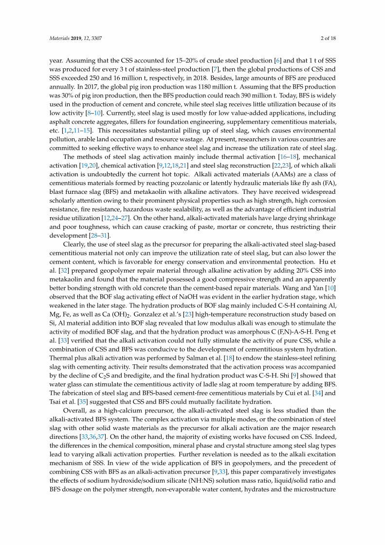
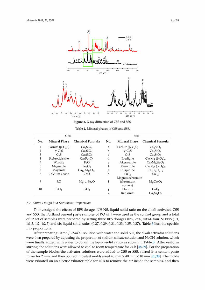
X-ray fluorescence (XRF) spectroscopy (XRF-1800, SHIMADZU, Kyoto, Japan) was used to analyze the chemical compositions of CSS, SSS and BFS (Table 1). X-ray diffraction (XRD, Bruker D8 ADVANCE, Bruker, Leipzig, Germany) was used to perform the phase analysis of CSS and SSS (Figure 2). Table 2 lists the details of phases. As can be seen, the main mineral components of CSS are Larnite (β-C2S), γ-C2S, C3S, Srebrodolskite, Wustite, Magnetite, Mayenite, CaO, RO, SiO2, etc. The main mineral components of SSS are γ-C2S, Larnite (β-C2S), C3S, Bredigite, Akermanite, Merwinite, Cuspidine, SiO2, Magnesiochromite (chromium spinels), Fluorite, Rankinite, etc. The cementitious activity of steel slag comes from C3S and C2S. The content of C3S is very small; while the main mineral phase C2S has two different crystalline forms, β-C2S and γ-C2S, in CSS and SSS.
Figure 1. Particle size distribution of carbon steel slag (CSS)/stainless steel slag (SSS)/blast furnace slag (BFS).
Table 1. Oxide composition of cementitious materials by XRF analysis (wt%).
Materials CaO SiO2 Al2O3 MgO Fe2O3 SO3 Cr2O3 MnO Ti2O CSS 41.36 19.79 9.78 4.02 20.73 0.47 0.55 1.06 0.77 SSS 39.90 34.19 12.30 2.28 4.70 0.64 1.88 0.55 1.30
0.01 0.1 1 10 100 1000
0
1
2
3
4
5
6
7
8
0.01 0.1 1 10 100 1000
0
20
40
60
80
100
Cum
ulat
ive
valu
e/%
Particle size/μm
Volu
me/
%
Particle size/μm
CSS SSS GGBFS
Figure 1. Particle size distribution of carbon steel slag (CSS)/stainless steel slag (SSS)/blast furnaceslag (BFS).
X-ray fluorescence (XRF) spectroscopy (XRF-1800, SHIMADZU, Kyoto, Japan) was used to analyzethe chemical compositions of CSS, SSS and BFS (Table 1). X-ray diffraction (XRD, Bruker D8 ADVANCE,Bruker, Leipzig, Germany) was used to perform the phase analysis of CSS and SSS (Figure 2). Table 2lists the details of phases. As can be seen, the main mineral components of CSS are Larnite (β-C2S),γ-C2S, C3S, Srebrodolskite, Wustite, Magnetite, Mayenite, CaO, RO, SiO2, etc. The main mineralcomponents of SSS are γ-C2S, Larnite (β-C2S), C3S, Bredigite, Akermanite, Merwinite, Cuspidine, SiO2,Magnesiochromite (chromium spinels), Fluorite, Rankinite, etc. The cementitious activity of steel slagcomes from C3S and C2S. The content of C3S is very small; while the main mineral phase C2S has twodifferent crystalline forms, β-C2S and γ-C2S, in CSS and SSS.
Table 1. Oxide composition of cementitious materials by XRF analysis (wt%).
Materials CaO SiO2 Al2O3 MgO Fe2O3 SO3 Cr2O3 MnO Ti2O
CSS 41.36 19.79 9.78 4.02 20.73 0.47 0.55 1.06 0.77SSS 39.90 34.19 12.30 2.28 4.70 0.64 1.88 0.55 1.30BFS 38.44 30.58 14.04 10.57 0.35 2.36 — 0.57 1.93
Cement 62.09 20.88 5.57 2.43 2.40 5.02 — — 0.31
Materials 2019, 12, 3307 4 of 18
Materials 2019, 12, x FOR PEER REVIEW 4 of 18
BFS 38.44 30.58 14.04 10.57 0.35 2.36 — 0.57 1.93 Cement 62.09 20.88 5.57 2.43 2.40 5.02 — — 0.31
Figure 2. X-ray diffraction of CSS and SSS.
Table 2. Mineral phases of CSS and SSS.
CSS SSS
No. Mineral Phase Chemical Formula No. Mineral Phase Chemical
Formula 1 Larnite (β-C2S) Ca2SiO4 a Larnite (β-C2S) Ca2SiO4 2 γ-C2S Ca2SiO4 b γ-C2S Ca2SiO4 3 C3S Ca3SiO5 c C3S Ca3SiO5 4 Srebrodolskite Ca2Fe2O5 d Bredigite Ca7Mg (SiO4)4 5 Wustite FeO e Akermanite Ca2MgSi2O7 6 Magnetite Fe3O4 f Merwinite Ca3Mg (SiO4)2 7 Mayenite Ca12Al14O33 g Cuspidine Ca4Si2O7F2 8 Calcium Oxide CaO h SiO2 SiO2
9 RO Mg1−xFexO i Magnesiochromite (chromium spinels)
MgCr2O4
10 SiO2 SiO2 j Fluorite CaF2 k Rankinite Ca3Si2O7
2.2. Mixes Design and Specimens Preparation
To investigate the effects of BFS dosage, NH:NS, liquid-solid ratio on the alkali-activated CSS and SSS, the Portland cement paste samples of P.O 42.5 were used as the control group and a total of 22 set of samples were prepared by setting three BFS dosages (0%, 25%, 50%), four NH:NS (1:1, 1:1.5,
10 20 30 40 50 60 70 80
bd
b
9
9
2
2
2θ (°)
SSS CSS
4
7
4
10
32 1
1
3
5
33 35
6
bi b b ie a
dad b
fb
b
35 36 37 38 39 40 41 42 43 44 45
9
1
3
33
18
61
CSS-2θ (°)
21 2
74
1
9
25 26 27 28 29 30 31 32 33 34 35
b
k
k d
d dg
g
f
d
d
d
cc
cb
b
a
a
j
h e
a
SSS-2θ (°)
eh h
b
f
Figure 2. X-ray diffraction of CSS and SSS.
Table 2. Mineral phases of CSS and SSS.
CSS SSS
No. Mineral Phase Chemical Formula No. Mineral Phase Chemical Formula
1 Larnite (β-C2S) Ca2SiO4 a Larnite (β-C2S) Ca2SiO42 γ-C2S Ca2SiO4 b γ-C2S Ca2SiO43 C3S Ca3SiO5 c C3S Ca3SiO54 Srebrodolskite Ca2Fe2O5 d Bredigite Ca7Mg (SiO4)45 Wustite FeO e Akermanite Ca2MgSi2O76 Magnetite Fe3O4 f Merwinite Ca3Mg (SiO4)27 Mayenite Ca12Al14O33 g Cuspidine Ca4Si2O7F28 Calcium Oxide CaO h SiO2 SiO2
9 RO Mg1−xFexO iMagnesiochromite
(chromiumspinels)
MgCr2O4
10 SiO2 SiO2 j Fluorite CaF2k Rankinite Ca3Si2O7
2.2. Mixes Design and Specimens Preparation
To investigate the effects of BFS dosage, NH:NS, liquid-solid ratio on the alkali-activated CSSand SSS, the Portland cement paste samples of P.O 42.5 were used as the control group and a totalof 22 set of samples were prepared by setting three BFS dosages (0%, 25%, 50%), four NH:NS (1:1,1:1.5, 1:2, 1:2.5) and six liquid-solid ratios (0.27, 0.29, 0.31, 0.33, 0.35, 0.37). Table 3 lists the specificmix proportions.
After preparing 10 mol/L NaOH solution with water and solid NH, the alkali activator solutionswere then prepared by adjusting the proportion of sodium silicate solution and NaOH solution, whichwere finally added with water to obtain the liquid-solid ratios as shown in Table 3. After uniformstirring, the solutions were allowed to cool to room temperature for 24 h [38,39]. For the preparationof the sample blocks, the activator solutions were added to CSS or SSS, stirred in a cement pastemixer for 2 min, and then poured into steel molds sized 40 mm × 40 mm × 40 mm [20,38]. The moldswere vibrated on an electric vibrator table for 40 s to remove the air inside the samples, and then
Materials 2019, 12, 3307 5 of 18
covered with polyester films and cured for 1 d in the T = 20 ± 1 ◦C, RH = 95 ± 1% conditions. Afterdemolding, the samples were further cured in the aforementioned conditions. At curing ages of 3 d,7 d, 28 d and 90 d, the unconfined compressive strength was examined. For the samples under tests ofnon-evaporable water content, XRD, TG-DTG (Thermogravimetry-Derivative Thermogravimetry),FT-IR and SEM-EDS, the net paste blocks needed to be cored, crushed and placed in acetone for 24 h toterminate hydration prior to the tests. Finally, after taking out and drying in an 80 ◦C to a constantweight [40], the samples were ground and sieved through a 0.07 mm mesh.
Table 3. Mix proportion of specimen’s paste.
Specimens Liquid-Solid Ratio NH:NSa BFS/CSSa Specimens Liquid-Solid Ratio NH:NS a BFS/CSS a
C2-29-0 0.29 1:2 0:100 S2-29-0 0.29 1:2 0:100C2-29-25 0.29 1:2 25:75 S2-29-25 0.29 1:2 25:75C2-29-50 0.29 1:2 50:50 S2-29-50 0.29 1:2 50:50C1-35-25 0.35 1:1 25:75 S1-35-25 0.35 1:1 25:75
C1.5-35-25 0.35 1:1.5 25:75 S1.5-35-25 0.35 1:1.5 25:75C2-35-25 0.35 1:2 25:75 S2-35-25 0.35 1:2 25:75
C2.5-35-25 0.35 1:2.5 25:75 S2.5-35-25 0.35 1:2.5 25:75C2-27-25 0.27 1:2 25:75 S2-27-25 0.27 1:2 25:75C2-31-25 0.31 1:2 25:75 S2-31-25 0.31 1:2 25:75C2-33-25 0.33 1:2 25:75 S2-33-25 0.33 1:2 25:75C2-37-25 0.37 1:2 25:75 S2-37-25 0.37 1:2 25:75
OPC 0.29 - - - - - -a mass ratio.
2.3. Testing Methods
2.3.1. Unconfined Compressive Strength Test
The TYE-300 compression testing machine (Jianyi Instrument & Machinery Co., Ltd., Wuxi, China)was used to test the unconfined compressive strengths of the samples at 1 d, 3 d, 7 d, 14 d, 28 d and90 d at a loading rate of 2.4 KN/s. The final strength value was obtained from the average of threesamples of the same condition [38,39].
2.3.2. Non-Evaporable Water Content Test
The non-evaporable water content, also known as the bound water content, was obtained bydividing the mass difference between the samples at 105 ◦C and 1000 ◦C by the mass at 105 ◦C. Thespecific test procedure and calculation method were the same as those used by Wang et al [20] and Yiet al [38].
2.3.3. Phase Analysis
D8 ADVANCE X-ray diffractometer (Bruker, Leipzig, Germany) was used to perform the phaseanalysis. The SSS series samples were tested with the copper target, while the CSS series sampleswere tested with the cobalt target. The reason for selecting the cobalt target was that the CSS samplescontained Fe element, which would generate strong fluorescent X-rays after being provoked. As aresult, diffraction backgrounds would be superposed, which was detrimental to the analysis. 2θ range:10–80◦; scan rate: 6 ◦/min; and scan step size: 0.02.
2.3.4. TG-DTG Analysis
STA 449 F3 thermal analyzer (Netzsch, Bavaria, Germany) was used to perform the TG-DTGanalysis. During the test, the temperature was raised from room temperature to 900 ◦C at a 10 ◦C/minrate under a nitrogen atmosphere.
Materials 2019, 12, 3307 6 of 18
2.3.5. FT-IR Analysis
The functional groups of the sample compounds were characterized with Nicolet iS10 FTIRspectrometer (Madison, WI, USA) for further analysis of the structural composition. The spectralrange was set to 400–4000 cm−1; the resolution was set as 0.09 cm−1; and the dynamic adjustment130,000 times/s.
2.3.6. Microstructure Analysis
JSM-7001F thermal field emission SEM (JEOL, Toky, Japan) was utilized to observe the samplemorphology at an accelerating voltage of 5 KV. Meanwhile, QX200 energy-dispersive spectrometer(Bruker, Germany) was used for direct qualitative and semi-quantitative observations of trace elementsin the specific micro-regions.
3. Results and Discussion
3.1. Unconfined Compressive Strength
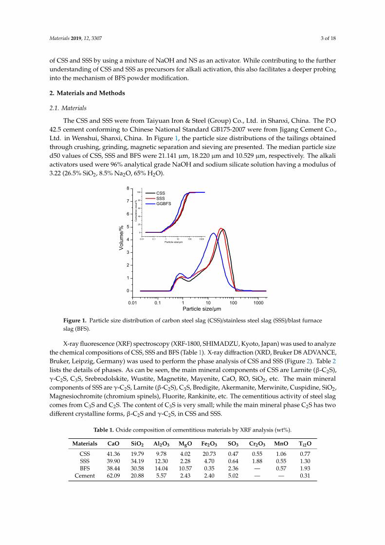
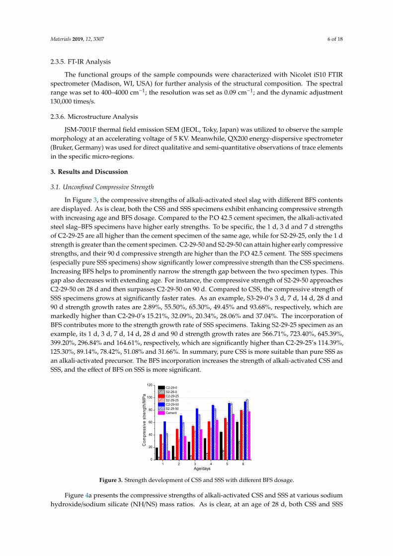
In Figure 3, the compressive strengths of alkali-activated steel slag with different BFS contentsare displayed. As is clear, both the CSS and SSS specimens exhibit enhancing compressive strengthwith increasing age and BFS dosage. Compared to the P.O 42.5 cement specimen, the alkali-activatedsteel slag–BFS specimens have higher early strengths. To be specific, the 1 d, 3 d and 7 d strengthsof C2-29-25 are all higher than the cement specimen of the same age, while for S2-29-25, only the 1 dstrength is greater than the cement specimen. C2-29-50 and S2-29-50 can attain higher early compressivestrengths, and their 90 d compressive strength are higher than the P.O 42.5 cement. The SSS specimens(especially pure SSS specimens) show significantly lower compressive strength than the CSS specimens.Increasing BFS helps to prominently narrow the strength gap between the two specimen types. Thisgap also decreases with extending age. For instance, the compressive strength of S2-29-50 approachesC2-29-50 on 28 d and then surpasses C2-29-50 on 90 d. Compared to CSS, the compressive strength ofSSS specimens grows at significantly faster rates. As an example, S3-29-0’s 3 d, 7 d, 14 d, 28 d and90 d strength growth rates are 2.89%, 55.50%, 65.30%, 49.45% and 93.68%, respectively, which aremarkedly higher than C2-29-0’s 15.21%, 32.09%, 20.34%, 28.06% and 37.04%. The incorporation ofBFS contributes more to the strength growth rate of SSS specimens. Taking S2-29-25 specimen as anexample, its 1 d, 3 d, 7 d, 14 d, 28 d and 90 d strength growth rates are 566.71%, 723.40%, 645.39%,399.20%, 296.84% and 164.61%, respectively, which are significantly higher than C2-29-25’s 114.39%,125.30%, 89.14%, 78.42%, 51.08% and 31.66%. In summary, pure CSS is more suitable than pure SSS asan alkali-activated precursor. The BFS incorporation increases the strength of alkali-activated CSS andSSS, and the effect of BFS on SSS is more significant.
Materials 2019, 12, x FOR PEER REVIEW 7 of 18
1 2 3 4 5 60
20
40
60
80
100
120
Com
pres
sive
stre
ngth
/MPa
Age/days
C2-29-0 S2-29-0 C2-29-25 S2-29-25 C2-29-50 S2-29-50 Cement
Figure 3. Strength development of CSS and SSS with different BFS dosage.
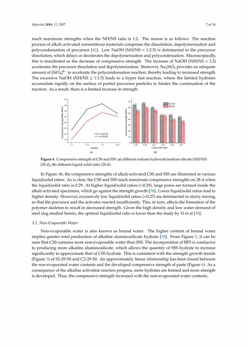
Figure 4a presents the compressive strengths of alkali-activated CSS and SSS at various sodium hydroxide/sodium silicate (NH/NS) mass ratios. As is clear, at an age of 28 d, both CSS and SSS reach maximum strengths when the NH/NS ratio is 1:2. The reason is as follows: The reaction process of alkali-activated cementitious materials comprises the dissolution, depolymerization and polycondensation of precursor [41]. Low NaOH (NH/NS = 1:2.5) is detrimental to the precursor dissolution, which delays or decelerates the depolymerization and polycondensation. Macroscopically, this is manifested as the decrease of compressive strength. The increase of NaOH (NH/NS = 1:2) accelerates the precursor dissolution and depolymerization. Moreover, Na2SiO3
provides an adequate amount of [SiO4]4− to accelerate the polycondensation reaction, thereby leading to increased strength. The excessive NaOH (NH/NS ≥ 1:1.5) leads to a hyper fast reaction, where the limited hydrates accumulate rapidly on the surface of partial precursor particles to hinder the continuation of the reaction. As a result, there is a limited increase in strength.
Figure 4. Compressive strength of CSS and SSS: (a) different sodium hydroxide/sodium silicate (NH/NS) (28 d); (b) different liquid-solid ratio (28 d).
In Figure 4b, the compressive strengths of alkali-activated CSS and SSS are illustrated at various liquid/solid ratios. As is clear, the CSS and SSS reach maximum compressive strengths on 28 d when the liquid/solid ratio is 0.29. At higher liquid/solid ratios (>0.29), large pores are formed inside the alkali-activated specimens, which go against the strength growth [38]. Lower liquid/solid ratios lead to higher density. However, excessively low liquid/solid ratios (<0.27) are detrimental to slurry mixing, so that the precursor and the activator reacted insufficiently. This, in turn, affects the formation of the polymer skeleton to result in decreased strength. Given the high density and low
1:1 1:1.5 1:2 1:2.5
15
20
25
30
35
40
45
50
Com
pres
sive
stre
ngth
/MPa
(MPa
)
NH/NS
C-35-25 S-35-25
64.2566.84
59.7
46.55 46.5543.53
54.33
59.61
55
45.62
38.9135.97
0.27 0.29 0.31 0.33 0.35 0.370
10
20
30
40
50
60
70
com
pres
sive
stre
ngth
(MPa
)
Liquid-solid ratio
C2-25 S2-25
(a) (b)
Figure 3. Strength development of CSS and SSS with different BFS dosage.
Figure 4a presents the compressive strengths of alkali-activated CSS and SSS at various sodiumhydroxide/sodium silicate (NH/NS) mass ratios. As is clear, at an age of 28 d, both CSS and SSS
Materials 2019, 12, 3307 7 of 18
reach maximum strengths when the NH/NS ratio is 1:2. The reason is as follows: The reactionprocess of alkali-activated cementitious materials comprises the dissolution, depolymerization andpolycondensation of precursor [41]. Low NaOH (NH/NS = 1:2.5) is detrimental to the precursordissolution, which delays or decelerates the depolymerization and polycondensation. Macroscopically,this is manifested as the decrease of compressive strength. The increase of NaOH (NH/NS = 1:2)accelerates the precursor dissolution and depolymerization. Moreover, Na2SiO3 provides an adequateamount of [SiO4]4− to accelerate the polycondensation reaction, thereby leading to increased strength.The excessive NaOH (NH/NS ≥ 1:1.5) leads to a hyper fast reaction, where the limited hydratesaccumulate rapidly on the surface of partial precursor particles to hinder the continuation of thereaction. As a result, there is a limited increase in strength.
Materials 2019, 12, x FOR PEER REVIEW 7 of 18
1 2 3 4 5 60
20
40
60
80
100
120
Com
pres
sive
stre
ngth
/MPa
Age/days
C2-29-0 S2-29-0 C2-29-25 S2-29-25 C2-29-50 S2-29-50 Cement
Figure 3. Strength development of CSS and SSS with different BFS dosage.
Figure 4a presents the compressive strengths of alkali-activated CSS and SSS at various sodium hydroxide/sodium silicate (NH/NS) mass ratios. As is clear, at an age of 28 d, both CSS and SSS reach maximum strengths when the NH/NS ratio is 1:2. The reason is as follows: The reaction process of alkali-activated cementitious materials comprises the dissolution, depolymerization and polycondensation of precursor [41]. Low NaOH (NH/NS = 1:2.5) is detrimental to the precursor dissolution, which delays or decelerates the depolymerization and polycondensation. Macroscopically, this is manifested as the decrease of compressive strength. The increase of NaOH (NH/NS = 1:2) accelerates the precursor dissolution and depolymerization. Moreover, Na2SiO3
provides an adequate amount of [SiO4]4− to accelerate the polycondensation reaction, thereby leading to increased strength. The excessive NaOH (NH/NS ≥ 1:1.5) leads to a hyper fast reaction, where the limited hydrates accumulate rapidly on the surface of partial precursor particles to hinder the continuation of the reaction. As a result, there is a limited increase in strength.
Figure 4. Compressive strength of CSS and SSS: (a) different sodium hydroxide/sodium silicate (NH/NS) (28 d); (b) different liquid-solid ratio (28 d).
In Figure 4b, the compressive strengths of alkali-activated CSS and SSS are illustrated at various liquid/solid ratios. As is clear, the CSS and SSS reach maximum compressive strengths on 28 d when the liquid/solid ratio is 0.29. At higher liquid/solid ratios (>0.29), large pores are formed inside the alkali-activated specimens, which go against the strength growth [38]. Lower liquid/solid ratios lead to higher density. However, excessively low liquid/solid ratios (<0.27) are detrimental to slurry mixing, so that the precursor and the activator reacted insufficiently. This, in turn, affects the formation of the polymer skeleton to result in decreased strength. Given the high density and low
1:1 1:1.5 1:2 1:2.5
15
20
25
30
35
40
45
50
Com
pres
sive
stre
ngth
/MPa
(MPa
)
NH/NS
C-35-25 S-35-25
64.2566.84
59.7
46.55 46.5543.53
54.33
59.61
55
45.62
38.9135.97
0.27 0.29 0.31 0.33 0.35 0.370
10
20
30
40
50
60
70
com
pres
sive
stre
ngth
(MPa
)
Liquid-solid ratio
C2-25 S2-25
(a) (b)
Figure 4. Compressive strength of CSS and SSS: (a) different sodium hydroxide/sodium silicate (NH/NS)(28 d); (b) different liquid-solid ratio (28 d).
In Figure 4b, the compressive strengths of alkali-activated CSS and SSS are illustrated at variousliquid/solid ratios. As is clear, the CSS and SSS reach maximum compressive strengths on 28 d whenthe liquid/solid ratio is 0.29. At higher liquid/solid ratios (>0.29), large pores are formed inside thealkali-activated specimens, which go against the strength growth [38]. Lower liquid/solid ratios lead tohigher density. However, excessively low liquid/solid ratios (<0.27) are detrimental to slurry mixing,so that the precursor and the activator reacted insufficiently. This, in turn, affects the formation of thepolymer skeleton to result in decreased strength. Given the high density and low water demand ofsteel slag studied herein, the optimal liquid/solid ratio is lower than the study by Yi et al [38].
3.2. Non-Evaporable Water
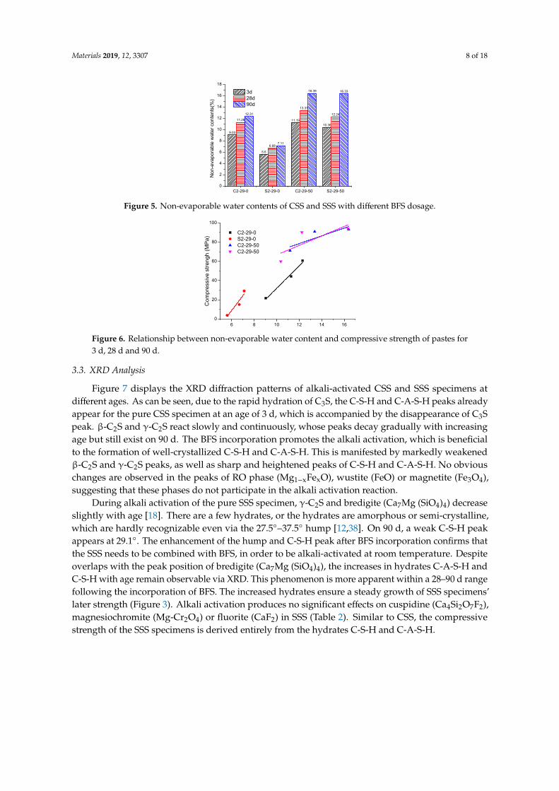
Non-evaporable water is also known as bound water. The higher content of bound waterimplies greater total production of alkaline aluminosilicate hydrate [38]. From Figure 5, it can beseen that CSS contains more non-evaporable water than SSS. The incorporation of BFS is conduciveto producing more alkaline aluminosilicate, which allows the quantity of SSS hydrate to increasesignificantly to approximate that of CSS hydrate. This is consistent with the strength growth trends(Figure 3) of S2-29-50 and C2-29-50. An approximately linear relationship has been found betweenthe non-evaporated water contents and the developed compressive strength of paste (Figure 6). As aconsequence of the alkaline activation reaction progress, more hydrates are formed and more strengthis developed. Thus, the compressive strength increased with the non-evaporated water contents.
Materials 2019, 12, 3307 8 of 18
Materials 2019, 12, x FOR PEER REVIEW 8 of 18
water demand of steel slag studied herein, the optimal liquid/solid ratio is lower than the study by Yi et al [38].
3.2. Non-Evaporable Water
Non-evaporable water is also known as bound water. The higher content of bound water implies greater total production of alkaline aluminosilicate hydrate [38]. From Figure 5, it can be seen that CSS contains more non-evaporable water than SSS. The incorporation of BFS is conducive to producing more alkaline aluminosilicate, which allows the quantity of SSS hydrate to increase significantly to approximate that of CSS hydrate. This is consistent with the strength growth trends (Figure 3) of S2-29-50 and C2-29-50. An approximately linear relationship has been found between the non-evaporated water contents and the developed compressive strength of paste (Figure 6). As a consequence of the alkaline activation reaction progress, more hydrates are formed and more strength is developed. Thus, the compressive strength increased with the non-evaporated water contents.
9.03
5.6
11.1910.36
11.28
6.68
13.37
12.2412.31
7.11
16.39 16.33
C2-29-0 S2-29-0 C2-29-50 S2-29-500
2
4
6
8
10
12
14
16
18
Non
-eva
pora
ble
wat
er c
onte
nts(
%)
3d 28d 90d
Figure 5. Non-evaporable water contents of CSS and SSS with different BFS dosage.
6 8 10 12 14 160
20
40
60
80
100
C2-29-0 S2-29-0 C2-29-50 C2-29-50
Com
pres
sive
stre
ngh
(MPa
)
Non-evaporable water contents(%) Figure 6. Relationship between non-evaporable water content and compressive strength of pastes for 3 d, 28 d and 90 d.
3.3. XRD Analysis
Figure 7 displays the XRD diffraction patterns of alkali-activated CSS and SSS specimens at different ages. As can be seen, due to the rapid hydration of C3S, the C-S-H and C-A-S-H peaks already appear for the pure CSS specimen at an age of 3 d, which is accompanied by the disappearance of C3S peak. β-C2S and γ-C2S react slowly and continuously, whose peaks decay gradually with increasing age but still exist on 90 d. The BFS incorporation promotes the alkali activation, which is beneficial to the formation of well-crystallized C-S-H and C-A-S-H. This is
Figure 5. Non-evaporable water contents of CSS and SSS with different BFS dosage.
Materials 2019, 12, x FOR PEER REVIEW 8 of 18
water demand of steel slag studied herein, the optimal liquid/solid ratio is lower than the study by Yi et al [38].
3.2. Non-Evaporable Water
Non-evaporable water is also known as bound water. The higher content of bound water implies greater total production of alkaline aluminosilicate hydrate [38]. From Figure 5, it can be seen that CSS contains more non-evaporable water than SSS. The incorporation of BFS is conducive to producing more alkaline aluminosilicate, which allows the quantity of SSS hydrate to increase significantly to approximate that of CSS hydrate. This is consistent with the strength growth trends (Figure 3) of S2-29-50 and C2-29-50. An approximately linear relationship has been found between the non-evaporated water contents and the developed compressive strength of paste (Figure 6). As a consequence of the alkaline activation reaction progress, more hydrates are formed and more strength is developed. Thus, the compressive strength increased with the non-evaporated water contents.
9.03
5.6
11.1910.36
11.28
6.68
13.37
12.2412.31
7.11
16.39 16.33
C2-29-0 S2-29-0 C2-29-50 S2-29-500
2
4
6
8
10
12
14
16
18
Non
-eva
pora
ble
wat
er c
onte
nts(
%)
3d 28d 90d
Figure 5. Non-evaporable water contents of CSS and SSS with different BFS dosage.
6 8 10 12 14 160
20
40
60
80
100
C2-29-0 S2-29-0 C2-29-50 C2-29-50
Com
pres
sive
stre
ngh
(MPa
)
Non-evaporable water contents(%) Figure 6. Relationship between non-evaporable water content and compressive strength of pastes for 3 d, 28 d and 90 d.
3.3. XRD Analysis
Figure 7 displays the XRD diffraction patterns of alkali-activated CSS and SSS specimens at different ages. As can be seen, due to the rapid hydration of C3S, the C-S-H and C-A-S-H peaks already appear for the pure CSS specimen at an age of 3 d, which is accompanied by the disappearance of C3S peak. β-C2S and γ-C2S react slowly and continuously, whose peaks decay gradually with increasing age but still exist on 90 d. The BFS incorporation promotes the alkali activation, which is beneficial to the formation of well-crystallized C-S-H and C-A-S-H. This is
Figure 6. Relationship between non-evaporable water content and compressive strength of pastes for3 d, 28 d and 90 d.
3.3. XRD Analysis
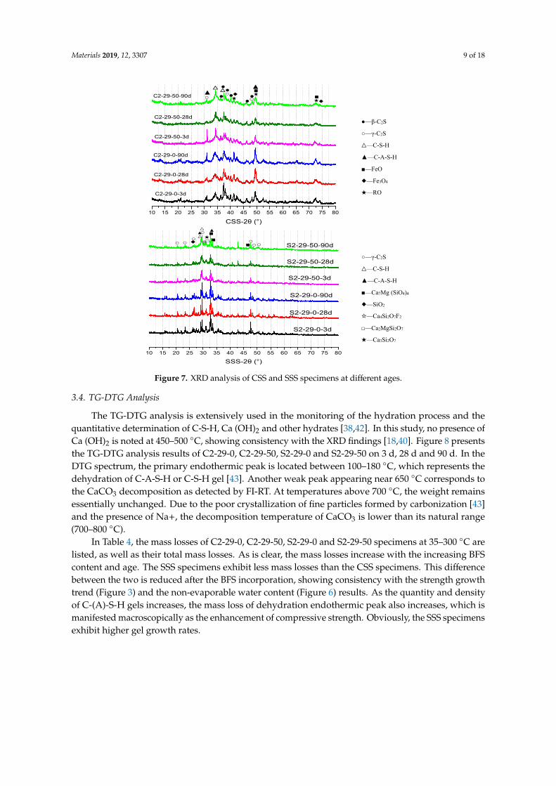
Figure 7 displays the XRD diffraction patterns of alkali-activated CSS and SSS specimens atdifferent ages. As can be seen, due to the rapid hydration of C3S, the C-S-H and C-A-S-H peaks alreadyappear for the pure CSS specimen at an age of 3 d, which is accompanied by the disappearance of C3Speak. β-C2S and γ-C2S react slowly and continuously, whose peaks decay gradually with increasingage but still exist on 90 d. The BFS incorporation promotes the alkali activation, which is beneficialto the formation of well-crystallized C-S-H and C-A-S-H. This is manifested by markedly weakenedβ-C2S and γ-C2S peaks, as well as sharp and heightened peaks of C-S-H and C-A-S-H. No obviouschanges are observed in the peaks of RO phase (Mg1−xFexO), wustite (FeO) or magnetite (Fe3O4),suggesting that these phases do not participate in the alkali activation reaction.
During alkali activation of the pure SSS specimen, γ-C2S and bredigite (Ca7Mg (SiO4)4) decreaseslightly with age [18]. There are a few hydrates, or the hydrates are amorphous or semi-crystalline,which are hardly recognizable even via the 27.5◦–37.5◦ hump [12,38]. On 90 d, a weak C-S-H peakappears at 29.1◦. The enhancement of the hump and C-S-H peak after BFS incorporation confirms thatthe SSS needs to be combined with BFS, in order to be alkali-activated at room temperature. Despiteoverlaps with the peak position of bredigite (Ca7Mg (SiO4)4), the increases in hydrates C-A-S-H andC-S-H with age remain observable via XRD. This phenomenon is more apparent within a 28–90 d rangefollowing the incorporation of BFS. The increased hydrates ensure a steady growth of SSS specimens’later strength (Figure 3). Alkali activation produces no significant effects on cuspidine (Ca4Si2O7F2),magnesiochromite (Mg-Cr2O4) or fluorite (CaF2) in SSS (Table 2). Similar to CSS, the compressivestrength of the SSS specimens is derived entirely from the hydrates C-S-H and C-A-S-H.
Materials 2019, 12, 3307 9 of 18
Materials 2019, 12, x FOR PEER REVIEW 9 of 18
manifested by markedly weakened β-C2S and γ-C2S peaks, as well as sharp and heightened peaks of C-S-H and C-A-S-H. No obvious changes are observed in the peaks of RO phase (Mg1−xFexO), wustite (FeO) or magnetite (Fe3O4), suggesting that these phases do not participate in the alkali activation reaction.
10 15 20 25 30 35 40 45 50 55 60 65 70 75 80
▲▲○ ◆●
◆★ ●● ○●●○●
△△
CSS-2θ (°)
C2-29-50-90d
C2-29-50-28d
C2-29-50-3d
C2-29-0-90d
C2-29-0-28d
C2-29-0-3d
★■★■
●—β-C2S
○—γ-C2S △—C-S-H
▲—C-A-S-H
■—FeO ◆—Fe3O4
★—RO
10 15 20 25 30 35 40 45 50 55 60 65 70 75 80
○★□☆ ■○
○◆▲△
○○ ○○△ ▲■
S2-29-0-3d
S2-29-0-28d
S2-29-0-90d
S2-29-50-3d
S2-29-50-28d
SSS-2θ (°)
S2-29-50-90d■
○—γ-C2S △—C-S-H
▲—C-A-S-H
■—Ca7Mg (SiO4)4 ◆—SiO2
☆—Ca4Si2O7F2
□—Ca2MgSi2O7
★—Ca3Si2O7
Figure 7. XRD analysis of CSS and SSS specimens at different ages.
During alkali activation of the pure SSS specimen, γ-C2S and bredigite (Ca7Mg (SiO4)4) decrease slightly with age [18]. There are a few hydrates, or the hydrates are amorphous or semi-crystalline, which are hardly recognizable even via the 27.5°–37.5° hump [12,38]. On 90 d, a weak C-S-H peak appears at 29.1°. The enhancement of the hump and C-S-H peak after BFS incorporation confirms that the SSS needs to be combined with BFS, in order to be alkali-activated at room temperature. Despite overlaps with the peak position of bredigite (Ca7Mg (SiO4)4), the increases in hydrates C-A-S-H and C-S-H with age remain observable via XRD. This phenomenon is more apparent within a 28–90 d range following the incorporation of BFS. The increased hydrates ensure a steady growth of SSS specimens' later strength (Figure 3). Alkali activation produces no significant effects on cuspidine (Ca4Si2O7F2), magnesiochromite (Mg-Cr2O4) or fluorite (CaF2) in SSS (Table 2). Similar to CSS, the compressive strength of the SSS specimens is derived entirely from the hydrates C-S-H and C-A-S-H.
3.4. TG-DTG Analysis
Figure 7. XRD analysis of CSS and SSS specimens at different ages.
3.4. TG-DTG Analysis
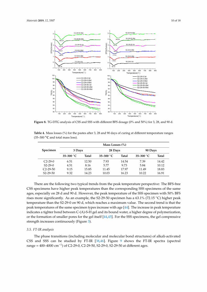
The TG-DTG analysis is extensively used in the monitoring of the hydration process and thequantitative determination of C-S-H, Ca (OH)2 and other hydrates [38,42]. In this study, no presence ofCa (OH)2 is noted at 450–500 ◦C, showing consistency with the XRD findings [18,40]. Figure 8 presentsthe TG-DTG analysis results of C2-29-0, C2-29-50, S2-29-0 and S2-29-50 on 3 d, 28 d and 90 d. In theDTG spectrum, the primary endothermic peak is located between 100–180 ◦C, which represents thedehydration of C-A-S-H or C-S-H gel [43]. Another weak peak appearing near 650 ◦C corresponds tothe CaCO3 decomposition as detected by FI-RT. At temperatures above 700 ◦C, the weight remainsessentially unchanged. Due to the poor crystallization of fine particles formed by carbonization [43]and the presence of Na+, the decomposition temperature of CaCO3 is lower than its natural range(700–800 ◦C).
In Table 4, the mass losses of C2-29-0, C2-29-50, S2-29-0 and S2-29-50 specimens at 35–300 ◦C arelisted, as well as their total mass losses. As is clear, the mass losses increase with the increasing BFScontent and age. The SSS specimens exhibit less mass losses than the CSS specimens. This differencebetween the two is reduced after the BFS incorporation, showing consistency with the strength growthtrend (Figure 3) and the non-evaporable water content (Figure 6) results. As the quantity and densityof C-(A)-S-H gels increases, the mass loss of dehydration endothermic peak also increases, which ismanifested macroscopically as the enhancement of compressive strength. Obviously, the SSS specimensexhibit higher gel growth rates.
Materials 2019, 12, 3307 10 of 18
Materials 2019, 12, x FOR PEER REVIEW 10 of 18
The TG-DTG analysis is extensively used in the monitoring of the hydration process and the quantitative determination of C-S-H, Ca (OH)2 and other hydrates [38,42]. In this study, no presence of Ca (OH)2 is noted at 450–500 °C, showing consistency with the XRD findings [18,40]. Figure 8 presents the TG-DTG analysis results of C2-29-0, C2-29-50, S2-29-0 and S2-29-50 on 3 d, 28 d and 90 d. In the DTG spectrum, the primary endothermic peak is located between 100–180 °C, which represents the dehydration of C-A-S-H or C-S-H gel [43]. Another weak peak appearing near 650 °C corresponds to the CaCO3 decomposition as detected by FI-RT. At temperatures above 700 °C, the weight remains essentially unchanged. Due to the poor crystallization of fine particles formed by carbonization [43] and the presence of Na+, the decomposition temperature of CaCO3 is lower than its natural range (700–800 °C).
100 200 300 400 500 600 700 800 900-1
0
1
2
3
4
5
Temperature( )℃
146.37
142.87
116.41
148.91
135.11
100.36
DTG
/(%/m
in)
C2-29-50-90d
C2-29-50-28d
C2-29-50-3d
C2-29-0-90d
C2-29-0-28d
C2-29-0-3d
100 200 300 400 500 600 700 800 900
-1
0
1
2
3
4
5
Temperature( )℃
186.49
133.93
140.94
114.34
115.23
99.72
S2-29-0-3d
DTG
/(%/m
in)
S2-29-50-90d
S2-29-50-28d
S2-29-50-3d
S2-29-0-90d
S2-29-0-28d
100 200 300 400 500 600 700 800 90080
82
84
86
88
90
92
94
96
98
100
102
C2-29-0-3d C2-29-0-28d C2-29-0-90d C2-29-50-3d C2-29-50-28d C2-29-50-90d
TG(%
)
Temperature( )℃ 100 200 300 400 500 600 700 800 900
80
82
84
86
88
90
92
94
96
98
100
102
TG(%
)
Temperature( )℃
S2-29-0-3d S2-29-0-28d S2-29-0-90d S2-29-50-3d S2-29-50-28d S2-29-50-90d
Figure 8. TG-DTG analysis of CSS and SSS with different BFS dosage (0% and 50%) for 3, 28, and 90 d.
In Table 4, the mass losses of C2-29-0, C2-29-50, S2-29-0 and S2-29-50 specimens at 35–300 °C are listed, as well as their total mass losses. As is clear, the mass losses increase with the increasing BFS content and age. The SSS specimens exhibit less mass losses than the CSS specimens. This difference between the two is reduced after the BFS incorporation, showing consistency with the strength growth trend (Figure 3) and the non-evaporable water content (Figure 6) results. As the quantity and density of C-(A)-S-H gels increases, the mass loss of dehydration endothermic peak also increases, which is manifested macroscopically as the enhancement of compressive strength. Obviously, the SSS specimens exhibit higher gel growth rates.
Table 4. Mass losses (%) for the pastes after 3, 28 and 90 days of curing at different temperature ranges (35–300 °C and total mass loss).
Specimen Mass Losses (%)
3 Days 28 Days 90 Days
Figure 8. TG-DTG analysis of CSS and SSS with different BFS dosage (0% and 50%) for 3, 28, and 90 d.
Table 4. Mass losses (%) for the pastes after 3, 28 and 90 days of curing at different temperature ranges(35–300 ◦C and total mass loss).
Specimen
Mass Losses (%)
3 Days 28 Days 90 Days
35–300 ◦C Tatal 35–300 ◦C Tatal 35–300 ◦C Tatal
C2-29-0 6.51 12.50 7.93 14.54 7.39 14.42S2-29-0 4.51 8.16 5.77 9.73 5.84 10.12
C2-29-50 9.15 15.85 11.45 17.97 11.49 18.83S2-29-50 9.32 14.23 10.03 16.23 10.22 16.91
There are the following two typical trends from the peak temperature perspective: The BFS-freeCSS specimens have higher peak temperatures than the corresponding SSS specimens of the sameages, especially on 28 d and 90 d. However, the peak temperature of the SSS specimen with 50% BFSrises more significantly. As an example, the S2-29-50 specimen has a 63.1% (72.15 ◦C) higher peaktemperature than the S2-29-0 on 90 d, which reaches a maximum value. The second trend is that thepeak temperatures of the same specimen types increase with age [44]. The increase in peak temperatureindicates a tighter bond between C-(A)-S-H gel and its bound water, a higher degree of polymerization,or the formation of smaller pores for the gel itself [44,45]. For the SSS specimens, the gel compressivestrength increases continuously (Figure 3).
3.5. FT-IR analysis
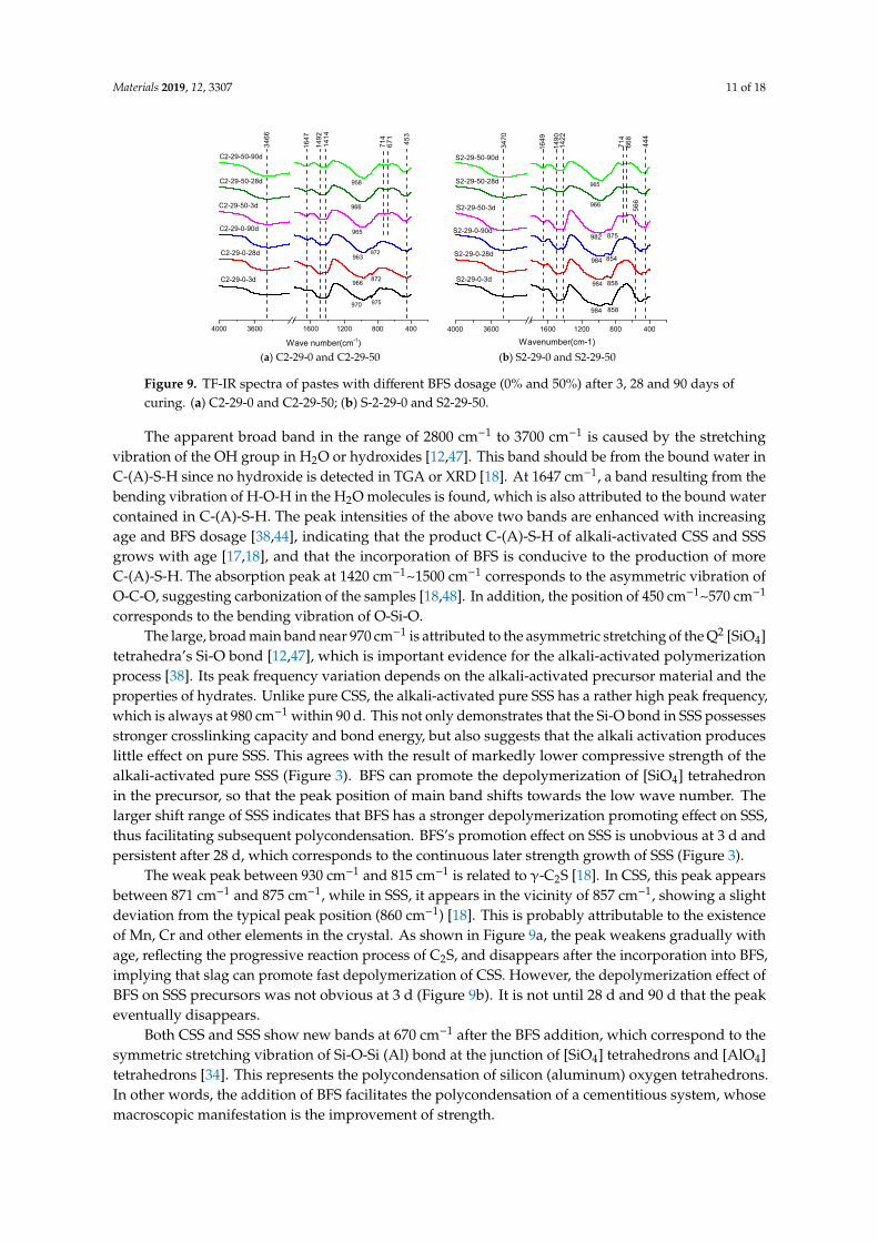
The phase transitions (including molecular and molecular bond structures) of alkali-activatedCSS and SSS can be studied by FT-IR [38,46]. Figure 9 shows the FT-IR spectra (spectralrange = 400–4000 cm−1) of C2-29-0, C2-29-50, S2-29-0, S2-29-50 at different ages.
Materials 2019, 12, 3307 11 of 18
Materials 2019, 12, x FOR PEER REVIEW 11 of 18
35–300 °C Tatal 35–300 °C Tatal 35–300 °C Tatal C2-29-0 6.51 12.50 7.93 14.54 7.39 14.42 S2-29-0 4.51 8.16 5.77 9.73 5.84 10.12
C2-29-50 9.15 15.85 11.45 17.97 11.49 18.83 S2-29-50 9.32 14.23 10.03 16.23 10.22 16.91
There are the following two typical trends from the peak temperature perspective: The BFS-free CSS specimens have higher peak temperatures than the corresponding SSS specimens of the same ages, especially on 28 d and 90 d. However, the peak temperature of the SSS specimen with 50% BFS rises more significantly. As an example, the S2-29-50 specimen has a 63.1% (72.15 °C) higher peak temperature than the S2-29-0 on 90 d, which reaches a maximum value. The second trend is that the peak temperatures of the same specimen types increase with age [44]. The increase in peak temperature indicates a tighter bond between C-(A)-S-H gel and its bound water, a higher degree of polymerization, or the formation of smaller pores for the gel itself [44,45]. For the SSS specimens, the gel compressive strength increases continuously (Figure 3).
3.5. FT-IR analysis
The phase transitions (including molecular and molecular bond structures) of alkali-activated CSS and SSS can be studied by FT-IR [38,46]. Figure 9 shows the FT-IR spectra (spectral range = 400–4000 cm−1) of C2-29-0, C2-29-50, S2-29-0, S2-29-50 at different ages.
Figure 9. TF-IR spectra of pastes with different BFS dosage (0% and 50%) after 3, 28 and 90 days of curing. (a) C2-29-0 and C2-29-50; (b) S-2-29-0 and S2-29-50.
The apparent broad band in the range of 2800 cm−1 to 3700 cm−1 is caused by the stretching vibration of the OH group in H2O or hydroxides [12,47]. This band should be from the bound water in C-(A)-S-H since no hydroxide is detected in TGA or XRD [18]. At 1647 cm−1, a band resulting from the bending vibration of H-O-H in the H2O molecules is found, which is also attributed to the bound water contained in C-(A)-S-H. The peak intensities of the above two bands are enhanced with increasing age and BFS dosage [38,44], indicating that the product C-(A)-S-H of alkali-activated CSS and SSS grows with age [17,18], and that the incorporation of BFS is conducive to the production of more C-(A)-S-H. The absorption peak at 1420 cm−1~1500 cm−1 corresponds to the asymmetric vibration of O-C-O, suggesting carbonization of the samples [18,48]. In addition, the position of 450 cm−1~570 cm−1 corresponds to the bending vibration of O-Si-O.
The large, broad main band near 970 cm−1 is attributed to the asymmetric stretching of the Q2 [SiO4] tetrahedra’s Si-O bond [12,47], which is important evidence for the alkali-activated polymerization process [38]. Its peak frequency variation depends on the alkali-activated precursor
4000 3600 1600 1200 800 400
714
671
453
1414
1492
1647
C2-29-0-3d
C2-29-0-28d
C2-29-0-90d
C2-29-50-3d
C2-29-50-28d
Wave number(cm-1)
C2-29-50-90d
3466
970
966
963
965
966
958
872
872
875
4000 3600 1600 1200 800 400
668
444
566
714
1422
1490
1649
3470
Wavenumber(cm-1)
S2-29-50-90d
S2-29-50-28d
S2-29-50-3d
S2-29-0-90d
S2-29-0-28d
S2-29-0-3d
965
966
982
984
984
984
875
854
858
858
(a) C2-29-0 and C2-29-50 (b) S2-29-0 and S2-29-50
Figure 9. TF-IR spectra of pastes with different BFS dosage (0% and 50%) after 3, 28 and 90 days ofcuring. (a) C2-29-0 and C2-29-50; (b) S-2-29-0 and S2-29-50.
The apparent broad band in the range of 2800 cm−1 to 3700 cm−1 is caused by the stretchingvibration of the OH group in H2O or hydroxides [12,47]. This band should be from the bound water inC-(A)-S-H since no hydroxide is detected in TGA or XRD [18]. At 1647 cm−1, a band resulting from thebending vibration of H-O-H in the H2O molecules is found, which is also attributed to the bound watercontained in C-(A)-S-H. The peak intensities of the above two bands are enhanced with increasingage and BFS dosage [38,44], indicating that the product C-(A)-S-H of alkali-activated CSS and SSSgrows with age [17,18], and that the incorporation of BFS is conducive to the production of moreC-(A)-S-H. The absorption peak at 1420 cm−1~1500 cm−1 corresponds to the asymmetric vibration ofO-C-O, suggesting carbonization of the samples [18,48]. In addition, the position of 450 cm−1~570 cm−1
corresponds to the bending vibration of O-Si-O.The large, broad main band near 970 cm−1 is attributed to the asymmetric stretching of the Q2 [SiO4]
tetrahedra’s Si-O bond [12,47], which is important evidence for the alkali-activated polymerizationprocess [38]. Its peak frequency variation depends on the alkali-activated precursor material and theproperties of hydrates. Unlike pure CSS, the alkali-activated pure SSS has a rather high peak frequency,which is always at 980 cm−1 within 90 d. This not only demonstrates that the Si-O bond in SSS possessesstronger crosslinking capacity and bond energy, but also suggests that the alkali activation produceslittle effect on pure SSS. This agrees with the result of markedly lower compressive strength of thealkali-activated pure SSS (Figure 3). BFS can promote the depolymerization of [SiO4] tetrahedronin the precursor, so that the peak position of main band shifts towards the low wave number. Thelarger shift range of SSS indicates that BFS has a stronger depolymerization promoting effect on SSS,thus facilitating subsequent polycondensation. BFS’s promotion effect on SSS is unobvious at 3 d andpersistent after 28 d, which corresponds to the continuous later strength growth of SSS (Figure 3).
The weak peak between 930 cm−1 and 815 cm−1 is related to γ-C2S [18]. In CSS, this peak appearsbetween 871 cm−1 and 875 cm−1, while in SSS, it appears in the vicinity of 857 cm−1, showing a slightdeviation from the typical peak position (860 cm−1) [18]. This is probably attributable to the existenceof Mn, Cr and other elements in the crystal. As shown in Figure 9a, the peak weakens gradually withage, reflecting the progressive reaction process of C2S, and disappears after the incorporation into BFS,implying that slag can promote fast depolymerization of CSS. However, the depolymerization effect ofBFS on SSS precursors was not obvious at 3 d (Figure 9b). It is not until 28 d and 90 d that the peakeventually disappears.
Both CSS and SSS show new bands at 670 cm−1 after the BFS addition, which correspond to thesymmetric stretching vibration of Si-O-Si (Al) bond at the junction of [SiO4] tetrahedrons and [AlO4]tetrahedrons [34]. This represents the polycondensation of silicon (aluminum) oxygen tetrahedrons.In other words, the addition of BFS facilitates the polycondensation of a cementitious system, whosemacroscopic manifestation is the improvement of strength.
Materials 2019, 12, 3307 12 of 18
3.6. SEM-EDS Analysis
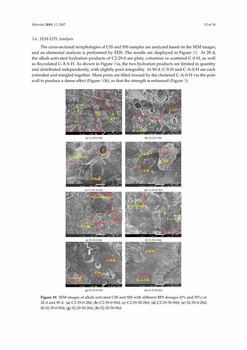
The cross-sectional morphologies of CSS and SSS samples are analyzed based on the SEM images,and an elemental analysis is performed by EDS. The results are displayed in Figure 10. At 28 d,the alkali-activated hydration products of C2-29-0 are platy, columnar or scattered C-S-H, as wellas flocculated C-A-S-H. As shown in Figure 10a, the two hydration products are limited in quantityand distributed independently, with slightly poor integrality. At 90 d, C-S-H and C-A-S-H are eachextended and mingled together. Most pores are filled inward by the clustered C-A-S-H via the porewall to produce a dense effect (Figure 10b), so that the strength is enhanced (Figure 3).
Materials 2019, 12, x FOR PEER REVIEW 12 of 18
material and the properties of hydrates. Unlike pure CSS, the alkali-activated pure SSS has a rather high peak frequency, which is always at 980 cm−1 within 90 d. This not only demonstrates that the Si-O bond in SSS possesses stronger crosslinking capacity and bond energy, but also suggests that the alkali activation produces little effect on pure SSS. This agrees with the result of markedly lower compressive strength of the alkali-activated pure SSS (Figure 3). BFS can promote the depolymerization of [SiO4] tetrahedron in the precursor, so that the peak position of main band shifts towards the low wave number. The larger shift range of SSS indicates that BFS has a stronger depolymerization promoting effect on SSS, thus facilitating subsequent polycondensation. BFS’s promotion effect on SSS is unobvious at 3 d and persistent after 28 d, which corresponds to the continuous later strength growth of SSS (Figure 3).
The weak peak between 930 cm−1 and 815 cm−1 is related to γ-C2S [18]. In CSS, this peak appears between 871 cm−1 and 875 cm−1, while in SSS, it appears in the vicinity of 857 cm−1, showing a slight deviation from the typical peak position (860 cm−1) [18]. This is probably attributable to the existence of Mn, Cr and other elements in the crystal. As shown in Figure 9a, the peak weakens gradually with age, reflecting the progressive reaction process of C2S, and disappears after the incorporation into BFS, implying that slag can promote fast depolymerization of CSS. However, the depolymerization effect of BFS on SSS precursors was not obvious at 3 d (Figure 9b). It is not until 28 d and 90 d that the peak eventually disappears.
Both CSS and SSS show new bands at 670 cm−1 after the BFS addition, which correspond to the symmetric stretching vibration of Si-O-Si (Al) bond at the junction of [SiO4] tetrahedrons and [AlO4] tetrahedrons [34]. This represents the polycondensation of silicon (aluminum) oxygen tetrahedrons. In other words, the addition of BFS facilitates the polycondensation of a cementitious system, whose macroscopic manifestation is the improvement of strength.
3.6. SEM-EDS Analysis
The cross-sectional morphologies of CSS and SSS samples are analyzed based on the SEM images, and an elemental analysis is performed by EDS. The results are displayed in Figure 10. At 28 d, the alkali-activated hydration products of C2-29-0 are platy, columnar or scattered C-S-H, as well as flocculated C-A-S-H. As shown in Figure 10a, the two hydration products are limited in quantity and distributed independently, with slightly poor integrality. At 90 d, C-S-H and C-A-S-H are each extended and mingled together. Most pores are filled inward by the clustered C-A-S-H via the pore wall to produce a dense effect (Figure 10b), so that the strength is enhanced (Figure 3).
(a) C2-29-0-28d (b) C2-29-0-90d
C-S-H
C-A-S-H
C-S-H RO
C-A-S-H
Materials 2019, 12, x FOR PEER REVIEW 13 of 18
Figure 10. SEM images of alkali-activated CSS and SSS with different BFS dosages (0% and 50%) at 28 d and 90 d. (a) C2-29-0-28d; (b) C2-29-0-90d; (c) C2-29-50-28d; (d) C2-29-50-90d; (e) S2-29-0-28d; (f) S2-29-0-90d; (g) S2-29-50-28d; (h) S2-29-50-90d.
Notably, S2-29-0 only produces small amounts of independent C-A-S-H at 28 d. Meanwhile, the remaining small particles are distributed in disorderly layers, which are formed by the sodium silicate bonding of non-polymerized raw materials (Figure 10e). As a result, the macroscopic strength becomes considerably low (Figure 3). At 90 d, C-A-S-H exhibits an increased quantity and flower cluster-like spread instead of a layered pattern, whose integrality though remains poor (Figure 10f). After adding BFS, C-(A)-S-H of C2-29-50 and S2-29-50 increased significantly, resulting in a remarkable increase in the sample compactness and integrality, which is in line with the trends of macroscopic strength development (Figure 3). The villous reaction ring peripheral to C2S particles
(c) C2-29-50-28d (d) C2-29-50-90d
(e) S2-29-0-28d (f) S2-29-0-90d
(g) S2-29-50-28d (h) S2-29-50-90d
C-S-H
RO C-A-S-H C-A-S-H
RO
C-S-H
C-A-S-H
Magnesiochromite
C-A-S-H
Magnesiochromite
C-A-S-H
C-S-H
C2S
C-A-S-H
C-S-H
Figure 10. SEM images of alkali-activated CSS and SSS with different BFS dosages (0% and 50%) at28 d and 90 d. (a) C2-29-0-28d; (b) C2-29-0-90d; (c) C2-29-50-28d; (d) C2-29-50-90d; (e) S2-29-0-28d;(f) S2-29-0-90d; (g) S2-29-50-28d; (h) S2-29-50-90d.
Materials 2019, 12, 3307 13 of 18
Notably, S2-29-0 only produces small amounts of independent C-A-S-H at 28 d. Meanwhile, theremaining small particles are distributed in disorderly layers, which are formed by the sodium silicatebonding of non-polymerized raw materials (Figure 10e). As a result, the macroscopic strength becomesconsiderably low (Figure 3). At 90 d, C-A-S-H exhibits an increased quantity and flower cluster-likespread instead of a layered pattern, whose integrality though remains poor (Figure 10f). After addingBFS, C-(A)-S-H of C2-29-50 and S2-29-50 increased significantly, resulting in a remarkable increasein the sample compactness and integrality, which is in line with the trends of macroscopic strengthdevelopment (Figure 3). The villous reaction ring peripheral to C2S particles in Figure 10g reflects theprogressive reaction process of C2S, which also guarantees the continuous growth of the SSS samplestrength in the later stage.
Both CSS and SSS contain inert phases, namely the RO phase and magnesiochromite. The ROphase has coarse grains and a smooth surface. After the addition of BFS, the RO phase surface isentangled by C-(A)-S-H only after going through a long period of time (Figure 10d), which is a weaklink of the gel structure. Meanwhile, magnesiochromite has a smooth and flat surface (Figure 10e).The magnesiochromite encapsulation performance of hydrate C-(A)-S-H (Figure 10f) reflects its Crsealing effect, a harmful heavy metal element.
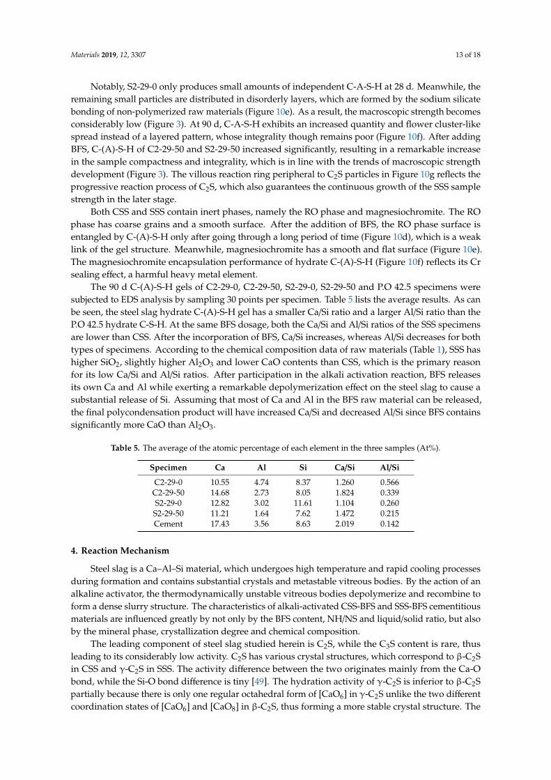
The 90 d C-(A)-S-H gels of C2-29-0, C2-29-50, S2-29-0, S2-29-50 and P.O 42.5 specimens weresubjected to EDS analysis by sampling 30 points per specimen. Table 5 lists the average results. As canbe seen, the steel slag hydrate C-(A)-S-H gel has a smaller Ca/Si ratio and a larger Al/Si ratio than theP.O 42.5 hydrate C-S-H. At the same BFS dosage, both the Ca/Si and Al/Si ratios of the SSS specimensare lower than CSS. After the incorporation of BFS, Ca/Si increases, whereas Al/Si decreases for bothtypes of specimens. According to the chemical composition data of raw materials (Table 1), SSS hashigher SiO2, slightly higher Al2O3 and lower CaO contents than CSS, which is the primary reasonfor its low Ca/Si and Al/Si ratios. After participation in the alkali activation reaction, BFS releasesits own Ca and Al while exerting a remarkable depolymerization effect on the steel slag to cause asubstantial release of Si. Assuming that most of Ca and Al in the BFS raw material can be released,the final polycondensation product will have increased Ca/Si and decreased Al/Si since BFS containssignificantly more CaO than Al2O3.
Table 5. The average of the atomic percentage of each element in the three samples (At%).
Specimen Ca Al Si Ca/Si Al/Si
C2-29-0 10.55 4.74 8.37 1.260 0.566C2-29-50 14.68 2.73 8.05 1.824 0.339S2-29-0 12.82 3.02 11.61 1.104 0.260S2-29-50 11.21 1.64 7.62 1.472 0.215Cement 17.43 3.56 8.63 2.019 0.142
4. Reaction Mechanism
Steel slag is a Ca–Al–Si material, which undergoes high temperature and rapid cooling processesduring formation and contains substantial crystals and metastable vitreous bodies. By the action of analkaline activator, the thermodynamically unstable vitreous bodies depolymerize and recombine toform a dense slurry structure. The characteristics of alkali-activated CSS-BFS and SSS-BFS cementitiousmaterials are influenced greatly by not only by the BFS content, NH/NS and liquid/solid ratio, but alsoby the mineral phase, crystallization degree and chemical composition.
The leading component of steel slag studied herein is C2S, while the C3S content is rare, thusleading to its considerably low activity. C2S has various crystal structures, which correspond to β-C2Sin CSS and γ-C2S in SSS. The activity difference between the two originates mainly from the Ca-Obond, while the Si-O bond difference is tiny [49]. The hydration activity of γ-C2S is inferior to β-C2Spartially because there is only one regular octahedral form of [CaO6] in γ-C2S unlike the two differentcoordination states of [CaO6] and [CaO8] in β-C2S, thus forming a more stable crystal structure. The
Materials 2019, 12, 3307 14 of 18
inferior hydration activity is also attributed to the absence of active oxygen atoms with high chargedensity in γ-C2S [50].
SSS has higher SiO2, slightly higher Al2O3 and lower CaO contents than CSS, and the oxidecomposition between SSS and BFS is closer, but pure SSS exhibits weaker alkali activation propertiesbecause of its higher crystallization degree (Figures 2 and 9).
As an excellent precursor [25,41], the activity of BFS is linked to the remote disordered vitreousstructure. The vitreous structure consists of a continuous Ca-rich phase with a rather large internalspecific surface area and a dense discontinuous Si-rich phase. The Si-O bond energy is approximatelythree times higher than that of Ca-O bond. During alkali activation, the high concentration OH− firstovercomes the decomposition and activation energies of Ca-rich phase to let it dissolve and expose theSi-rich phase. The reaction of the Si-rich phase occurs subsequently, but persistently and slowly [51].Ca2+ in the glass phase increases the disorderliness of structure, which acts as a network correctorto distort and depolymerize the network structure, thereby reducing the polymerization degree ofraw material [41]. The BFS incorporation allows the production of more hydrates (Figure 8). It alsofacilitates the depolymerization of γ-C2S and shifts the asymmetric stretching of Q2 tetrahedra’s Si-Obond towards a low wave number, which is accompanied by peak intensity decay of γ-C2S (Figure 9).
Similar to the alkali-activated BFS, the primary hydrate of alkali-activated steel slag is amorphousC-(A)-S-H gel in a Q2 [SiO4] tetrahedral form. The addition of Al3+ elongates the chain length ofC-(A)-S-H [52–54], which correspond to the shift of the peak position near 970 cm−1 towards a low wavenumber direction and the formation of a new absorption peak near 670 cm−1 (Figure 9). The C-(A)-S-Hafter Al substitution is uniform (Figure 10) and dense with high strength (Figure 3).
The strength of alkali-activated steel slag cementitious system comes from the hydrate C-(A)-S-H,and Si-rich raw materials are conducive to the production of more C-(A)-S-H hydrate. Unlike CSS,the Si-O bond of alkali-activated pure SSS shows unobvious depolymerization due to the high γ-C2Scontent and the doping of elements like Mn and Cr, thus resulting in a limited polycondensationeffect and low strength. After the incorporation of BFS, on the one hand, C-(A)-S-H is formed bydepolymerization and recombination of BFS to enhance the strength. On the other hand, porousC-(A)-S-H with large specific surface area acts as a “seed” [55,56], adsorbing free water, increasingOH- concentration in the system, promoting depolymerization and improving the pore structure. As aresult, the band near 980 cm−1 in SSS shifts significantly towards the low wave number (Figure 9).Once depolymerized, the higher Si content of SSS than CSS ensures the growth of C-(A)-S-H to allowthe continuous strength enhancement.
The alkali activation process is accompanied by a decrease in the active products (Figure 7), suchas C3S, β-C2S in CSS and γ-C2S, bredigite in SSS. However, the inert phases, such as the RO phase(Mg1−xFexO), wustite (FeO), magnetite (Fe3O4) in CSS and cuspidine (Ca4Si2O7F2), magnesiochromite(Mg-Cr2O4), fluorite (CaF2) in SSS, do not participate in the reaction (SEM image) (Figure 10). To someextent, the presence of these inert phases forms a weak area of slurry, thereby weakening the alkaliactivation effect.
5. Conclusions
In this paper, the hydration properties of alkali-activated CSS/SSS–BFS cementitious materialsare studied. The BFS content, NH/NS and liquid/solid ratio all affect the strength and hydrationprogression of the studied materials. The following conclusions are drawn:
(1) The quantity of C-(A)-S-H, the primary hydrate of alkali-activated steel slag cementitiousmaterials, determines the materials’ hydration properties, such as the strength and non-evaporablewater content. C-(A)-S-H increases with the increasing BFS content. For CSS and SSS, the optimalalkali dosage is NH/NS = 1:2, which can balance the depolymerization and polycondensation, and theoptimal liquid/solid ratio is 0.29, which ensures the formation of the gel skeleton and the compactnessof paste.
Materials 2019, 12, 3307 15 of 18
(2) The contents of steel slag’s mineral components β-C2S, γ-C2S and chemical components,including CaO, SiO2 and Al2O3, determine their alkali activation performance as a precursor. SSS isnot easily alkali-activated due to the stable crystal structure of γ-C2S, which is reflected in the delayor even termination of depolymerization. Nevertheless, its high Al2O3 and SiO2 contents elevate itspotential as a precursor. Without doubt, depolymerization is important for steel slag, especially for SSS.
(3) BFS’s beneficial seed effect on the alkali activation of steel slag is reflected in two aspects: Theproduction of C-(A)-S-H through the alkali activation and the promotion of steel slag depolymerization.The increase in the BFS content is helpful for producing C-(A)-S-H gel with high Ca/Si and low Al/Siratios, thus improving the gel density. Compared with CSS, SSS has higher SiO2, slightly higher Al2O3,and lower CaO, resulting in SSS-BFS gel with lower Ca/Si and Al/Si ratios than CSS-BFS gel.
(4) The inert phases in the steel slag like RO and magnesiochromite do not participate in thealkali activation reaction. In the gel system, they are encapsulated by C-(A)-S-H to form a weak link.This proves, from another perspective, that the alkali-activated steel slag possesses sealing propertiesagainst harmful metals like Cr.
(5) Considering the effect and cost of alkali activation, pure CSS can be used as a precursor, whileSSS needs to be activated jointly with BFS.
Author Contributions: J.L., responsible for the overall design of the experiment and the writing of manuscripts;C.Y., responsible for the experimental funding and experimental guidance; H.Z., responsible for literature retrievaland experimental guidance; H.M., responsible for data collection and analysis.
Funding: This research was sponsored by the National Natural Science Foundation of China (NSFC, NO.51578539),Solid Waste Comprehensive Utilization Science and Technology Project of Xiangyuan County (2018XYSDYY-07)from China, Key Research and Development (R&D) Projects of Shanxi Province (201803D31029). The authorsgratefully acknowledge test support from materials and durability laboratory of China University of Mining andTechnology (Beijing).
Conflicts of Interest: The authors declared that have no conflicts of interest to this work. We declare that we donot have any commercial or associative interest that represents a conflict of interest in connection with the worksubmitted. We declare that the funding agency does not affect the submission of manuscripts.
References
1. Jiang, Y.; Ling, T.C.; Shi, C.J.; Pan, S.Y. Characteristics of steel slags and their use in cement and concrete—Areview. Resour. Conserv. Recycl. 2018, 136, 187–197. [CrossRef]
2. Yi, H.; Xu, G.P.; Cheng, H.G.; Wang, J.S.; Wan, Y.F.; Chen, H. An overview of utilization of steel slag. InProceedings of the 7th International Conference on Waste Management and Technology, Ancona, Italy, 12–14May 2014; pp. 791–801.
3. Shi, W.; Li, H.; Liao, G.; Pei, G.; Lin, Y. Carbon steel slag and stainless steel slag for removal of arsenic fromstimulant and real groundwater. Int. J. Environ. Sci. Technol. 2018, 15, 2337–2348. [CrossRef]
4. World Steel Association. Steel Statistical Yearbook 2018; World Steel Association: Brussels, Belgium, 2018.5. ISSF. Available online: http://www.worldstainless.org/crude_steel_production/crude_2018 (accessed on 20
September 2019).6. Pacheco, T.F.; Castro, G.J.; Jalali, S. Alkali-activated binders: A review. Part 2. About materials and binders
manufacture. Constr. Build. Mater. 2008, 22, 1315–1322. [CrossRef]7. Le, D.H.; Sheen, Y.N.; Bui, Q.B. An assessment on volume stabilization of mortar with stainless steel slag
sand. Constr. Build. Mater. 2017, 155, 200–208. [CrossRef]8. Wu, X.; Hong, Z.; Hou, X.; Li, H. Study on steel slag and fly ash composite Portland cement. Cem. Concr. Res.
1999, 29, 1103–1106.9. Shi, C.J. Characteristics and cementitious properties of ladle slag fines from steel production. Cem. Concr.
Res. 2002, 32, 459–462. [CrossRef]10. Wang, Q.; Yan, P.Y. Hydration properties of basic oxygen furnace steel slag. Constr. Build. Mater. 2010, 24,
1134–1140. [CrossRef]

Materials 2019, 12, 3307 16 of 18
11. Li, Z.B.; Zhao, S.Y.; Zhao, X.G.; He, T.S. Cementitious property modification of basic oxygen furnace steelslag. Constr. Build. Mater. 2013, 48, 575–579. [CrossRef]
12. Liu, Z.; Zhang, D.W.; Li, L.; Wang, J.X.; Shao, N.N.; Wang, D.M. Microstructure and phase evolution ofalkali-activated steel slag during early age. Constr. Build. Mater. 2019, 204, 158–165. [CrossRef]
13. Sheen, Y.N.; Wang, H.Y.; Sun, T.H. A study of engineering properties of cement mortar with stainless steeloxidizing slag and reducing slag resource materials. Constr. Build. Mater. 2013, 40, 239–245. [CrossRef]
14. Yuksel, I. A review of steel slag usage in construction industry for sustainable development. Environ. Dev.Sustain. 2017, 19, 369–384. [CrossRef]
15. Shi, C.J. Steel Slag—Its Production, Processing, Characteristics, and Cementitious Properties. J. Mater. Civil.Eng. 2004, 16, 230–236. [CrossRef]
16. Shi, C.J.; Hu, S.F. Cementitious properties of ladle slag fines under autoclave curing conditions. Cem. Concr.Res. 2003, 33, 1851–1856. [CrossRef]
17. Salman, M.; Cizer, Ö.; Pontikes, Y.; Vandewalle, L.; Blanpain, B.; Koen, V.B. Effect of curing temperatureson the alkali activation of crystalline continuous casting stainless steel slag. Constr. Build. Mater. 2014, 71,308–316. [CrossRef]
18. Salman, M.; Cizer, Ö.; Pontikes, Y.; Snellings, R.; Vandewalle, L.; Blanpain, B.; Koen, V.B. Cementitiousbinders from activated stainless steel refining slag and the effect of alkali solutions. J. Hazard. Mater. 2015,286, 211–219. [CrossRef]
19. Kriskova, L.; Pontikes, Y.; Cizer, Ö.; Mertens, G.; Veulemans, W.; Geysen, D.; Jones, P.T.; Vandewalle, L.;Koen, V.B.; Blanpain, B. Effect of mechanical activation on the hydraulic properties of stainless steel slags.Cem. Concr. Res. 2012, 42, 778–788. [CrossRef]
20. Wang, Q.; Yang, J.W.; Yan, P.Y. Cementitious properties of super-fine steel slag. Powder Technol. 2013, 245,35–39. [CrossRef]
21. Yang, S.G.; Wang, J.F.; Cui, S.P.; Liu, H.; Wang, X.L. Impact of four kinds of alkanolamines on hydration ofsteel slag-blended cementitious materials. Constr. Build. Mater. 2017, 131, 655–666. [CrossRef]
22. Kriskova, L.; Eroli, M.; Iacobescu, R.I.; Onisei, S.; Vecchiocattivi, F.; Pontike, Y. Transformation of stainlesssteel slag toward a reactive cementitious binder. J. Am. Ceram. Soc. 2018, 101, 1727–1736. [CrossRef]
23. Gonzalez, P.L.L.; Novais, R.M.; Labrincha, J.A.; Blanpain, B.; Pontikes, Y. Modifications ofbasic-oxygen-furnace slag microstructure and their effect on the rheology and the strength of alkali-activatedbinders. Cem. Concr. Res. 2019, 97, 143–153. [CrossRef]
24. Provis, J.L.; Palomo, A.; Shi, C.J. Advances in understanding alkali-activated materials. Cem. Concr. Res.2015, 78, 110–125. [CrossRef]
25. Luukkonen, T.; Abdollahnejad, Z.; Yliniemi, J.; Kinnunen, P.; Illikainen, M. One-part alkali-activated materials:A review. Cem. Concr. Res. 2018, 103, 21–34. [CrossRef]
26. Liu, Y.Q.; Zhu, W.P.; Yang, E.H. Alkali-activated ground granulated blast-furnace slag incorporatingincinerator fly ash as a potential binder. Constr. Build. Mater. 2016, 112, 1005–1012. [CrossRef]
27. Zhang, Y.J.; Liu, L.C.; Xu, Y.; Wang, Y.C.; Xu, D.L. A new alkali-activated steel slag-based cementitiousmaterial for photocatalytic degradation of organic pollutan from waste water. J. Hazard. Mater. 2012, 209,146–150. [CrossRef]
28. Sakulich, A.R.; Miller, A.; Barsoum, M.W. Chemical and microstructural characterization of 20-month-oldalkali activated slag cement. J. Am. Ceram. Soc. 2010, 93, 1741–1748. [CrossRef]
29. Melo, A.A.; Cincotto, M.A.; Repette, W.L. Drying and autogenous shrinkage of pastes and mortars withactivated slag. Cem. Concr. Res. 2008, 38, 565–574. [CrossRef]
30. Cengiz, D.A.; Cahit, B.; Özlem, Ç. Influence of activator on the strength and drying shrinkage ofalkali-activated slag mortar. Constr. Build. Mater. 2009, 23, 548–555.
31. Collins, F.; Sanjayan, J.G. Cracking tendency of alkali-activated slag concrete subjected to restrained shrinkage.Cem. Concr. Res. 2000, 30, 791–798. [CrossRef]
32. Hu, S.G.; Wang, H.X.; Zhang, G.Z.; Ding, Q.J. Bonding and abrasion resistance of geopolymeric repairmaterial made with steel slag. Cement. Concrete. Comp. 2008, 30, 239–244. [CrossRef]
33. Peng, X.Q.; Liu, C.; Li, S.; Jiang, Y.; Zeng, L. Research on the setting and hardening performance ofalkali-activated steel slag-slag based cementitious materials. J. Hunan Univ. 2015, 42, 47–52. (In Chinese)
Materials 2019, 12, 3307 17 of 18
34. Cui, X.W.; Ni, W.; Ren, C. Hydration Mechanism of All Solid Waste Cementitious Materials Based on SteelSlag and Blast Furnace Slag. Chin. J. Mater. Res. 2017, 31, 687–693. (In Chinese)
35. Tsai, C.J.; Huang, R.; Lin, W.T.; Wang, H.N. Mechanical and cementitious characteristics of ground granulatedblast furnace slag and basic oxygen furnace slag blended mortar. Mater. Des. 2014, 60, 267–273. [CrossRef]
36. Kriskova, L.; Pontikes, Y.; Zhang, F.; Jones, P.T.; Balen, K.V.; Blanpain, B. Influence of mechanical andchemical activation on the hydraulic properties of gamma dicalcium silicate. Cem. Concr. Res. 2014, 55,59–68. [CrossRef]
37. Kriskova, L.; Pontikes, Y.; Cizer, O.; Malfliet, A.; Dijkmans, J.; Sels, B.; Balen, K.V.; Blanpain, B. Hydraulicbehavior of mechanically and chemically activated synthetic merwinite. J. Am. Ceram. Soc. 2014, 97,3973–3981. [CrossRef]
38. Yi, C.; Ma, H.Q.; Chen, H.Y.; Wang, J.X.; Shi, J.; Li, Z.H.; Yu, M.K. Preparation and characterization of coalgangue geopolymers. Constr. Build. Mater. 2018, 187, 318–326.
39. Cheng, H.; Lin, K.L.; Cui, R.; Hwang, C.L.; Chang, Y.M.; Cheng, T.W. The effects of SiO2/Na2O molar ratio onthe characteristics of alkali-activated waste catalyst–metakaolin based geopolymers. Constr. Build. Mater.2018, 95, 710–720. [CrossRef]
40. Lee, N.K.; Lee, H.K. Reactivity and reaction products of alkali-activated, fly ash/slag paste. Constr. Build.Mater. 2015, 81, 303–312. [CrossRef]
41. Li, C.; Sun, H.H.; Li, L.T. A review: The comparison between alkali-activated slag (Si+Ca) and metakaolin(Si+Al) cements. Cem. Concr. Res. 2010, 40, 1341–1349. [CrossRef]
42. Firdous, R.; Stephan, D.; Djobo, J.N.Y. Natural pozzolan based geopolymers: A review on mechanical,microstructural and durability characteristics. Constr. Build. Mater. 2018, 190, 1251–1263. [CrossRef]
43. Moraes, J.C.B.; Tashima, M.M.; Akasaki, J.L.; Melges, J.L.P.; Monzó, J.; Borrachero, M.V.; Soriano, L.;Payá, J. Effect of sugar cane straw ash (SCSA) as solid precursor and the alkaline activator composition onalkali-activated binders based on blast furnace slag (BFS). Constr. Build. Mater. 2017, 144, 214–224. [CrossRef]
44. Ismail, I.; Bernal, S.A.; Provis, J.L.; Nicolas, R.S.; Hamdan, S.; Deventer, J.S.J.V. Modification of phase evolutionin alkali-activated blast furnace slag by the incorporation of fly ash. Cem. Concr. Comp. 2014, 45, 125–135.[CrossRef]
45. Nochaiya, T.; Wongkeo, W.; Pimraksa, K.; Chaipanich, A. Microstructural, physical, and thermal analyses ofPortland cement–fly ash–calcium hydroxide blended pastes. J. Therm. Anal. Calorim. 2010, 100, 101–108.[CrossRef]
46. Tuyan, M.; Andiç-Çakir, Ö.; Ramyar, K. Effect of alkali activator concentration and curing condition onstrength and microstructure of waste clay brick powder-based geopolymer. Compos. Part B Eng. 2018, 135,242–252. [CrossRef]
47. Yu, P.; Kirkpatrick, R.J.; Poe, B.; McMillan, P.F.; Cong, X. Structure of calcium silicate hydrate (CSH): Near-,mid-, and far-infrared spectroscopy. J. Am. Ceram. Soc. 1999, 82, 742–748. [CrossRef]
48. Heikala, M.; Nassar, M.Y.; El-Sayed, G.; Ibrahim, S.M. Physico-chemical, mechanical, microstructure anddurability characteristics of alkali activated Egyptian slag. Constr. Build. Mater. 2014, 69, 60–72. [CrossRef]
49. Feng, X.J.; Min, X.M. Study on the structure and characteristic of dicalcium silicate with quantum chemistrycalculations. J. Wuhan Univ. Technol. 1994, 16, 1–6. (In Chinese)
50. Salman, M.; Cizer, O.; Pontikes, Y.; Snellings, R.; Dijkman, J.; Sels, B.; Vandewalle, L.; Blanpain, B.; Balen, K.V.Alkali Activation of AOD Stainless Steel Slag Under Steam Curing Conditions. J. Am. Ceram. Soc. 2015, 98,3062–3074. [CrossRef]
51. Xu, B.; Pu, X.C. Study on the relationship between the phase separation of slag glass and the latent hydraulicactivity of BFS. J. Chin. Ceram. Soc. 1997, 25, 729–733.
52. Puertas, F.; Palacios, M.; Manzano, H.; Dolado, J.S.; Rico, A.; Rodríguez, J. A model for the C-A-S-H gelformed in alkali-activated slag cements. J. Eur. Ceram. Soc. 2011, 31, 2043–2056. [CrossRef]
53. Lodeiro, I.G.; Jimenez, A.F.; Palomo, A.; Macphee, D.E. Effect on fresh C-S-H gels of the simultaneousaddition of alkali and aluminium. Cem. Concr. Res. 2010, 40, 27–32. [CrossRef]
54. Renaudin, G.; Russias, J.; Leroux, F.; Cau-dit-Coumes, C.; Frizon, F. Structural characterization of C–S–H andC–A–S–H samples—Part II: Local environment investigated by spectroscopic analyses. J. Solid State Chem.2009, 182, 3320–3329. [CrossRef]

Materials 2019, 12, 3307 18 of 18
55. Yang, J.B.; Li, D.X.; Fang, Y. Effect of synthetic CaO-Al2O3-SiO2-H2O on the early-stage performance ofalkali-activated slag. Constr. Build. Mater. 2018, 167, 65–72. [CrossRef]
56. Thomas, J.J.; Jennings, H.M.; Chen, J.J. Influence of Nucleation Seeding on the Hydration Mechanisms ofTricalcium Silicate and Cement. J. Phys. Chem. C 2009, 113, 4327–4334. [CrossRef]
© 2019 by the authors. Licensee MDPI, Basel, Switzerland. This article is an open accessarticle distributed under the terms and conditions of the Creative Commons Attribution(CC BY) license (http://creativecommons.org/licenses/by/4.0/).


![Waste glass as binder in alkali activated slag–fly ash mortars · 2019-10-22 · alkali activated slag [24]. However, compared to the water glass, the influence of waste glass](https://img.pdfslide.us/doc/110x75/5f5d066b7c86da04f679d9b7/waste-glass-as-binder-in-alkali-activated-slagafly-ash-mortars-2019-10-22-alkali.jpg)