Embed Size (px)
Citation preview
Abstract—Unmanned aerial vehicles, UAV, has increases in
the drastically in these past several years since their costs
reduced. This research is based and built upon previous
research presented in a conference. With the advent of
commercial Quadcopters, four propeller systems, are used,
being designed and used to operate the advantages of both flight
and hovering. The basic design of their propeller blades has not
evolved from the early days of manned flight when wooden fixed
blades were used. In this paper that expands upon previous
findings and discussions it explores the historical developments.
Furthermore, how the expansion and reduction in costs of
modern materials and manufacturing techniques that offer more
accurate matching of blades’ needs and applications.
Index Terms—Aerodynamics, blade design, efficiency and
flight stability.
I. INTRODUCTION
Student of aviation are aware from early studies of Kitty
Hawk on the 17th
December, 1903, the Wright Brothers first
undertook powered man-flight. This epoch stands alongside
the first time man broke the speed of sound and landing on the
moon. Now set as a seminal date for what is known as
Aviation and a complete new mode of transportation that has
changed to world in many different ways. Within 66 years
man set-off by a rocket to walk on the moon and returned
safely. Technology usually advances at rapid paces when it
offers commercial possibilities, opportunities or War dictates
the necessity for advantages.
The UAV market is built upon innovation and parallels can
be drawn between the start of manned flight and UAV flight.
In 1903, the parallels stop as all technology was new and not
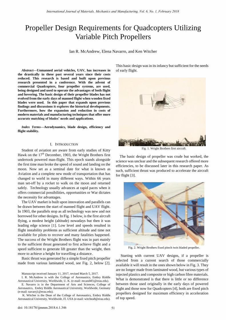
borrowed for other designs. In Fig. 1 below, is the first aircraft
flying, a modest height (altitude) nowadays but then it was
leading edge science [1]. Low level and speeds resulted in
flight instability problems as sufficient altitude and time not
available for pilots to recover and many fatalities happened.
The success of the Wright Brothers flight was in part mainly
to the sufficient thrust generated to first achieve flight and a
speed sufficient to generate lift greater than the weight, then
more to achieve a height for travelling a distance.
Basic thrust was generated by a simple fixed pitch propeller
made from various laminated wood, see Fig. 2, below [2].
Manuscript received January 11, 2017, revised March 5, 2017.
I. R. McAndrew is with the College of Aeronautics, Embry Riddle
Aeronautical University, Worldwide, U. K. (e-mail: [email protected]).
E. Navarro is in the Department of Arts and Sciences, College of
Aeronautics, Embry Riddle Aeronautical University, Worldwide, Germany
(e-mail: [email protected]).
K. Witcher is the Dean of the College of Aeronautics, Embry Riddle
Aeronautical University, Worldwide, Fl. USA (e-mail: [email protected]).
This basic design was in its infancy but sufficient for the needs
of early flight.
Fig. 1. Wright Brothers first aircraft.
The basic design of propeller was crude but worked, the
science was unclear and the subsequent research offered more
efficiencies, to be discussed later in this research paper. As
such, sufficient thrust was produced to accelerate the aircraft
for flight [3].
Fig. 2. Wright Brothers fixed pitech twin bladed propeller.
Starting with current UAV designs, if a propeller is
selected from a current search of those commercially
available it will result in the ones shown below in Fig. 3. They
are no longer made from laminated wood, but various types of
injected plastics and composite or high carbon fibre materials.
What is demonstrated is that there is little or no difference
between those used originally in the early days of powered
flight and those now for Quadcopters [4], both are fixed pitch
propellers designed for maximum efficiency in acceleration
of top speed.
Propeller Design Requirements for Quadcopters Utilizing
Variable Pitch Propellers
Ian R. McAndrew, Elena Navarro, and Ken Witcher
International Journal of Materials, Mechanics and Manufacturing, Vol. 6, No. 1, February 2018
51doi: 10.18178/ijmmm.2018.6.1.346
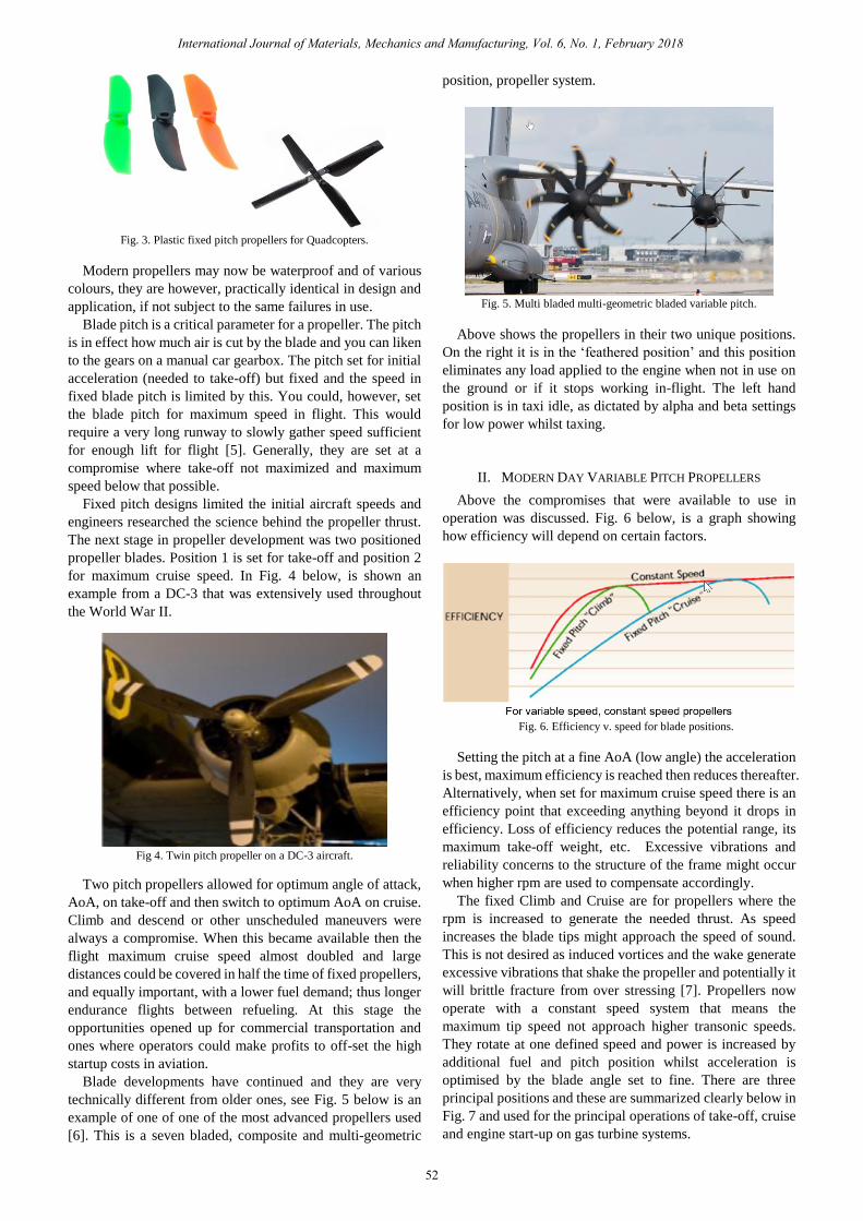
Fig. 3. Plastic fixed pitch propellers for Quadcopters.
Modern propellers may now be waterproof and of various
colours, they are however, practically identical in design and
application, if not subject to the same failures in use.
Blade pitch is a critical parameter for a propeller. The pitch
is in effect how much air is cut by the blade and you can liken
to the gears on a manual car gearbox. The pitch set for initial
acceleration (needed to take-off) but fixed and the speed in
fixed blade pitch is limited by this. You could, however, set
the blade pitch for maximum speed in flight. This would
require a very long runway to slowly gather speed sufficient
for enough lift for flight [5]. Generally, they are set at a
compromise where take-off not maximized and maximum
speed below that possible.
Fixed pitch designs limited the initial aircraft speeds and
engineers researched the science behind the propeller thrust.
The next stage in propeller development was two positioned
propeller blades. Position 1 is set for take-off and position 2
for maximum cruise speed. In Fig. 4 below, is shown an
example from a DC-3 that was extensively used throughout
the World War II.
Fig 4. Twin pitch propeller on a DC-3 aircraft.
Two pitch propellers allowed for optimum angle of attack,
AoA, on take-off and then switch to optimum AoA on cruise.
Climb and descend or other unscheduled maneuvers were
always a compromise. When this became available then the
flight maximum cruise speed almost doubled and large
distances could be covered in half the time of fixed propellers,
and equally important, with a lower fuel demand; thus longer
endurance flights between refueling. At this stage the
opportunities opened up for commercial transportation and
ones where operators could make profits to off-set the high
startup costs in aviation.
Blade developments have continued and they are very
technically different from older ones, see Fig. 5 below is an
example of one of one of the most advanced propellers used
[6]. This is a seven bladed, composite and multi-geometric
position, propeller system.
Fig. 5. Multi bladed multi-geometric bladed variable pitch.
Above shows the propellers in their two unique positions.
On the right it is in the „feathered position‟ and this position
eliminates any load applied to the engine when not in use on
the ground or if it stops working in-flight. The left hand
position is in taxi idle, as dictated by alpha and beta settings
for low power whilst taxing.
II. MODERN DAY VARIABLE PITCH PROPELLERS
Above the compromises that were available to use in
operation was discussed. Fig. 6 below, is a graph showing
how efficiency will depend on certain factors.
Fig. 6. Efficiency v. speed for blade positions.
Setting the pitch at a fine AoA (low angle) the acceleration
is best, maximum efficiency is reached then reduces thereafter.
Alternatively, when set for maximum cruise speed there is an
efficiency point that exceeding anything beyond it drops in
efficiency. Loss of efficiency reduces the potential range, its
maximum take-off weight, etc. Excessive vibrations and
reliability concerns to the structure of the frame might occur
when higher rpm are used to compensate accordingly.
The fixed Climb and Cruise are for propellers where the
rpm is increased to generate the needed thrust. As speed
increases the blade tips might approach the speed of sound.
This is not desired as induced vortices and the wake generate
excessive vibrations that shake the propeller and potentially it
will brittle fracture from over stressing [7]. Propellers now
operate with a constant speed system that means the
maximum tip speed not approach higher transonic speeds.
They rotate at one defined speed and power is increased by
additional fuel and pitch position whilst acceleration is
optimised by the blade angle set to fine. There are three
principal positions and these are summarized clearly below in
Fig. 7 and used for the principal operations of take-off, cruise
and engine start-up on gas turbine systems.
International Journal of Materials, Mechanics and Manufacturing, Vol. 6, No. 1, February 2018
52
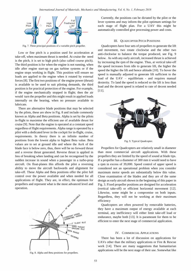
Fig. 7. Three principal positions of a variable pitch propeller.
Low or fine pitch is a position used for acceleration at
take-off, when maximum thrust is needed. At cruise the need
is the pitch, it is set to high pitch (also called course pitch).
The third position is for when the engine is not running, when
idle after engine start-up on gas turbine systems or if the
engine stops working in flight. This position will ensure no
loads are applied to the engine when it rotated by external
forces [8]. The first two positions of the engine power (thrust)
is available to be used to suit piloting demands, the third
position is for practical protection of the engine. For example,
if the engine mechanically stopped in flight; then the air
would turn the propeller and this might result in applied loads
internally on the bearing, when no pressure available to
lubricate.
There are alternative blade positions that may be selected
by the pilots, these are show in Fig. 8 and include commonly
known as Alpha and Beta positions. Alpha is set by the pilots
in-flight to maximise the efficient use of available thrust for
cruise [9]. Note that the engine is operated at a constant speed
regardless of flight requirements. Alpha range is operated by a
pilot with a dedicated lever in the cockpit for in-flight, cruise,
requirements. In theory there is an infinite number of
positions from the lowest alpha to highest Beta value. Beta
values are to set at ground idle and where the AoA of the
blade face is below zero, thus, there will be no forward thrust
and a reverse thrust generated. Reverse thrust is applied in
lieu of breaking when landing and can be recongnised by the
sudden increase in sound when a passenger in a turbo-prop
aircraft. On float-planes this affords the pilot a reversing
ability to move the aircraft backwards and alignment for
take-off. These Alpha and Beta positions offer the pilot full
control over the power available and when needed for all
applications of flight. They are, in effect, the optimum for
propellers and represent what is the most advanced level and
operation.
Fig. 8. Alpha and Beta positions for propellers.
Currently, the positions can be dictated by the pilot or the
lever systems and may inform the pilot optimum settings for
each stage of flight plan. For a UAV this might be
automatically controlled give processing power and costs.
III. QUADCOPTER PITCH POSITIONS
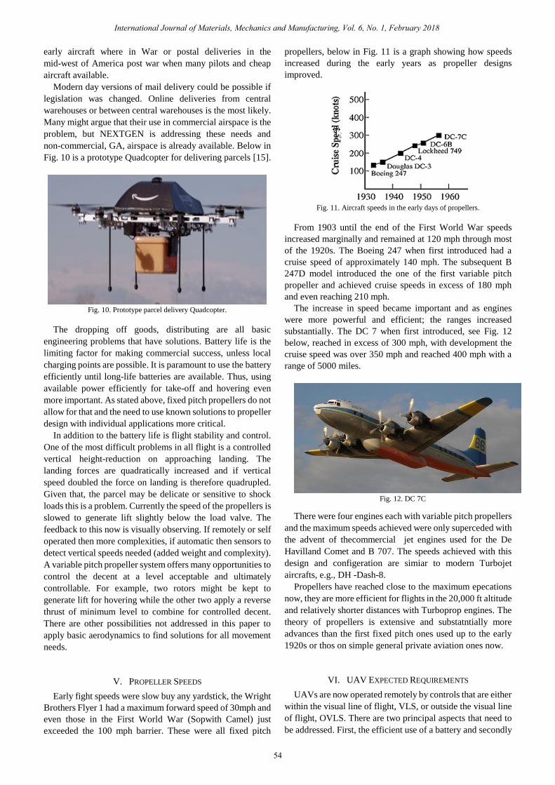
Quadcopters have four sets of propellers to generate the lift
and movement, two rotate clockwise and the other two
anti-clockwise to balance the torque produced, see Fig. 9
below. As with any early aircraft, increased thrust is achieved
by increasing the rpm of the engine. Thus, at vertical take-off
the speed increases from idle to generate lift, the higher the
speed the higher the lift and hence altitude [10]. To hover the
speed is manually adjusted to generate lift sufficient to the
load of the UAV – equilibrium - and requires manual
dexterity. To land the speed is reduced so the lift is less than
load and the decent speed is related to rate of decent needed
[11].
Fig. 9. Typical Quadcopter.
Propellers for Quadcopters are relatively small in diameter
than most commercial aircraft applications. With these
propellers they are limited by the speed of sound at blade tips.
If a propeller has a diameter of 300 mm it would need to have
a rpm in excess of 39,000. Speed control of upper speed is
considered not an operational problem when you consider
maximum motor speeds are substantially below this value.
Close examination of the blades and they are of the same
design as early aircraft shown in the beginning of this paper in
Fig. 3. Fixed propeller positions are designed for acceleration
(vertical take-off) or efficient horizontal movement [12].
Likewise, some might be a compromise on both inputs.
Regardless, they will not be working at their maximum
efficiency
Quadcopters are often powered by removable batteries,
they have a maximum output of energy available at each
terminal, any inefficiency will either limit take-off load or
endurance, maybe both [13]. It is paramount for them to be
efficient to enter the next stage of commercial application.
IV. COMMERCIAL APPLICATIONS
There has been a lot of discussion on applications for
UAVs other than the military applications or Fire & Rescue
work [14]. There are many suggestions that humanitarian
applications will be the next stage of their use. Somewhat like
International Journal of Materials, Mechanics and Manufacturing, Vol. 6, No. 1, February 2018
53
early aircraft where in War or postal deliveries in the
mid-west of America post war when many pilots and cheap
aircraft available.
Modern day versions of mail delivery could be possible if
legislation was changed. Online deliveries from central
warehouses or between central warehouses is the most likely.
Many might argue that their use in commercial airspace is the
problem, but NEXTGEN is addressing these needs and
non-commercial, GA, airspace is already available. Below in
Fig. 10 is a prototype Quadcopter for delivering parcels [15].
Fig. 10. Prototype parcel delivery Quadcopter.
The dropping off goods, distributing are all basic
engineering problems that have solutions. Battery life is the
limiting factor for making commercial success, unless local
charging points are possible. It is paramount to use the battery
efficiently until long-life batteries are available. Thus, using
available power efficiently for take-off and hovering even
more important. As stated above, fixed pitch propellers do not
allow for that and the need to use known solutions to propeller
design with individual applications more critical.
In addition to the battery life is flight stability and control.
One of the most difficult problems in all flight is a controlled
vertical height-reduction on approaching landing. The
landing forces are quadratically increased and if vertical
speed doubled the force on landing is therefore quadrupled.
Given that, the parcel may be delicate or sensitive to shock
loads this is a problem. Currently the speed of the propellers is
slowed to generate lift slightly below the load valve. The
feedback to this now is visually observing. If remotely or self
operated then more complexities, if automatic then sensors to
detect vertical speeds needed (added weight and complexity).
A variable pitch propeller system offers many opportunities to
control the decent at a level acceptable and ultimately
controllable. For example, two rotors might be kept to
generate lift for hovering while the other two apply a reverse
thrust of minimum level to combine for controlled decent.
There are other possibilities not addressed in this paper to
apply basic aerodynamics to find solutions for all movement
needs.
V. PROPELLER SPEEDS
Early fight speeds were slow buy any yardstick, the Wright
Brothers Flyer 1 had a maximum forward speed of 30mph and
even those in the First World War (Sopwith Camel) just
exceeded the 100 mph barrier. These were all fixed pitch
propellers, below in Fig. 11 is a graph showing how speeds
increased during the early years as propeller designs
improved.
Fig. 11. Aircraft speeds in the early days of propellers.
From 1903 until the end of the First World War speeds
increased marginally and remained at 120 mph through most
of the 1920s. The Boeing 247 when first introduced had a
cruise speed of approximately 140 mph. The subsequent B
247D model introduced the one of the first variable pitch
propeller and achieved cruise speeds in excess of 180 mph
and even reaching 210 mph.
The increase in speed became important and as engines
were more powerful and efficient; the ranges increased
substantially. The DC 7 when first introduced, see Fig. 12
below, reached in excess of 300 mph, with development the
cruise speed was over 350 mph and reached 400 mph with a
range of 5000 miles.
Fig. 12. DC 7C
There were four engines each with variable pitch propellers
and the maximum speeds achieved were only superceded with
the advent of thecommercial jet engines used for the De
Havilland Comet and B 707. The speeds achieved with this
design and configeration are simiar to modern Turbojet
aircrafts, e.g., DH -Dash-8.
Propellers have reached close to the maximum epecations
now, they are more efficient for flights in the 20,000 ft altitude
and relatively shorter distances with Turboprop engines. The
theory of propellers is extensive and substatntially more
advances than the first fixed pitch ones used up to the early
1920s or thos on simple general private aviation ones now.
VI. UAV EXPECTED REQUIREMENTS
UAVs are now operated remotely by controls that are either
within the visual line of flight, VLS, or outside the visual line
of flight, OVLS. There are two principal aspects that need to
be addressed. First, the efficient use of a battery and secondly
International Journal of Materials, Mechanics and Manufacturing, Vol. 6, No. 1, February 2018
54
by having more control in vertical accent and especially
decent. This paper proposes the use of variable pitch
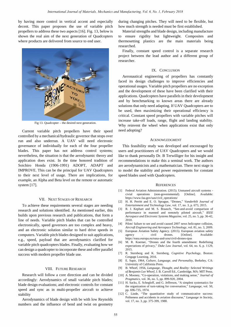
propellers to address these two aspects [16]. Fig. 13, below is
shown the real aim of the next generation of Quadcopters
where products are delivered from source to end user.
Fig 13. Quadcopter – the desired next generation.
Current variable pitch propellers have their speed
controlled by a mechanical/hydraulic governor that stops over
run and also underrun. A UAV will need electronic
governance of individually for each of the four propeller
blades. This paper has not address control systems;
nevertheless, the situation is that the aerodynamic theory and
application does exist. In the time honored tradition of
Soichiro Honda (1906-1991) ADOPT, ADAPT and
IMPROVE. This can be the principal for UAV Quadcopters
to their next level of usage. There are implications, for
example, an Alpha and Beta level on the remote or automatic
system [17].
VII. NEXT STAGES OF RESEARCH
To achieve these requirements several stages are needing
research and solutions identified. As mentioned earlier, this
builds upon previous research and publications, that form a
line of needs. Variable pitch blades that can be controlled
electronically, speed governors are too complex and heavy,
and an electronic solution similar to hard drive speeds in
computers. Variable pitch blades designed to suit applications,
e.g., speed, payload that are aerodynamics clarified for
variable pitch quadcopters blades. Finally, evaluating how we
can design a quadcopter to incorporate these and offer parallel
success with modern propeller blade use.
VIII. FUTURE RESEARCH
Research will follow a core direction and can be divided
accordingly: Aerodynamics of small variable pitch blades;
blade design evaluations; and electronic controls for constant
speed and sync as in multi-propeller aircraft to achieve
stability
Aerodynamics of blade design with be with low Reynolds
numbers and the influence of bend and twist on geometry
during changing pitches. They will need to be flexible, but
how much strength is needed must be first established.
Material strengths and blade design, including manufacture
to ensure rigidity but lightweight. Composites and
thermosetting plastics are the main materials being
researched.
Finally, constant speed control is a separate research
project between the lead author and a different group of
researcher.
IX. CONCLUSION
Aeronautical engineering of propellers has constantly
faced its design challenges to improve efficiencies and
operational usages. Variable pitch propellers are no exception
and the development of these have been clarified with their
applications. Quadcopters have parallels in their development
and by benchmarking to known areas there are already
solutions that only need adapting. If UAV Quadcopters are to
be used, then maximizing their operational efficiency is
critical. Constant speed propellers with variable pitches will
increase take-off loads, range, flight and landing stability.
Why reinvent the wheel when applications exist that only
need adopting?
ACKNOWLEDGMENT
This feasibility study was developed and encouraged by
users and practitioners of UAV Quadcopters and we would
like to thank personally Dr. B Terwilliger for his insight and
recommendations to make this a seminal work. The authors
are aerodynamicists and a mathematician. There next stage is
to model the stability and power requirements for constant
speed blades used with Quadcopters.
REFERENCES
[1] Federal Aviation Administration. (2015). Unmaned aircraft systems -
civial operations (non-governmental). [Online]. Available:
https://www.faa.gov/uas/civil_operations/
[2] H. H. Perritt and E. O. Sprague, “Drones,” Vanderbilt Journal of
Entertainment and Technology Law, vol. 17, no. 3, p. 673, 2015.
[3] R. J. Kephart and M. S. Braasch, “See-and-avoid comparison of
performance in manned and remotely piloted aircraft,” IEEE
Aerospace and Electronic Systems Magazine, vol. 25, no. 5, pp. 36-42,
2010.
[4] Pilots' failure to see and avoid caused 2007 news helicopter collision,
Aircraft Engineering and Aerospace Technology, vol. 81, no. 3, 2009.
[5] European Aviation Safety Agency. (2015). European aviation safety
agency - civil drones. [Online]. Available:
https://easa.europa.eu/easa-and-you/civil-drones-rpas
[6] M. R. Koerner, “Drones and the fourth amendment: Redefining
expectations of privacy,” Duke Law Journal, vol. 64, no. 6, p. 1129,
2015.
[7] R. Sternberg and K. Sternberg, Cognitive Psychology, Boston:
Cengage Learning, 2016.
[8] E. Sapir, 1964, Culture, Language, and Personality, Berkeley, CA:
University of California Press.
[9] B. Whorf, 1956, Language, Thought, and Reality: Selected Writings
of Benjamin Lee Whorf, J. B. Carroll Ed., Cambridge, MA: MIT Press.
[10] A. Mooney, “Co-operation, violations, and making sense,” Journal of
Pragmatics, vol. 36, no. 5, pp. 899-920, 2004.
[11] H. Sacks, E. Schegloff, and G. Jefferson, “A simplest systematics for
the organization of turn-taking for conversation,” Language, vol. 50,
pp. 696-735, 1974.
[12] C. Linde, “The quantitative study of communicative success:
Politeness and accidents in aviation discourse,” Language in Society,
vol. 17, no. 3, pp. 375-399, 1988.
International Journal of Materials, Mechanics and Manufacturing, Vol. 6, No. 1, February 2018
55
[13] J. Sexton and R. Helmreich, “Analyzing cockpit communications: The
links between language, performance, error, and workload,” Journal of
Human Performance in Extreme Environments, vol. 5, no. 1, 63-68,
2000.
[14] I. R. McAndrew, A. Carruthers, and E. Navarro, “Hypersonic
unmanned aerial vehicles: A case for rapid deployment of specialised
cargo,” 2014.
[15] S. A. Beebe, S. J. Beebe, and M. V. Redmond, Interpersonal
Communication: Relating Toothers, 7th ed. Upper Saddle River, NJ:
Pearson, 2014.
[16] T. Tiewtrakul and S. R. Fletcher, “The challenge of regional accents for
aviation English Language proficiency standards: A study in
difficulties in understanding in air traffic control-pilot
communications,” Ergonomics, vol. 53, no. 2, pp. 229-239, 2010.
[17] International Journal of Unmanned Systems Engineering, World
Congress on Unmanned Systems Engineering, vol. 2, no. 3, pp. 80-85,
University of Oxford, Oxford, UK, 30th July – 1st August.
Ian R. McAndrew is the department chair for Embry
Riddle Aeronautical University – Worldwide, College
of Aeronautics. He has a PhD, master‟s and
undergraduate degree in mechanical engineering. In
addition, a master‟s in education and another
undergraduate degree in manufacturing. He lives and
works in the UK, where all his degrees were awarded.
Dr McAndrew is also a Chartered Electrical Engineer.
His current research interests are in low speed
aerodynamics and the statistics of reliability in design.
Before entering education, he worked in the Automotive industry where
he held several patent for automation of engine assembly and manufacture.
He is the author of several books and conference proceedings. Additionally,
he has examined PhD globally and has taught in more than 20 countries
during his academic career.
Dr. Ian R. McAndrew PhD FRAeS is a professor of Aeronautics at his
university and tenured. He is a member of several institutions and external
examiner at two UK Universities.
Author‟s formal
photo
International Journal of Materials, Mechanics and Manufacturing, Vol. 6, No. 1, February 2018
56