Embed Size (px)
Citation preview
TEST REPORT
06-07/2008
20 TELE-satellite & Broadband — 06-07/2008 — www.TELE-satellite.com
State of the Art Universal Signal Analyzer
Satellite Meter and Analyzer
Promax TV Explorer II+PROMAX TV EXPLORER II+
Promax at its best! A must for satellite professionals; ergonomic and
universally usable with sun-proof display

▲
21www.TELE-satellite.com — 06-07/2008 — TELE-satellite & Broadband
When you have to precisely align several satellite and ter-restrial TV and radio antennas, then mix all the incoming sig-nals and distribute them among many different apartments in a building, you need some-thing much more sophisticated. That’s where the TV Explorer II+ from Promax comes into play. This instrument is so ver-satile that it’s difficult to find a proper name for it. Is it: a fieldstrength meter, a spectrum analyzer, a satellite finder, atest receiver or a constellation diagram meter? Is it for analog or digital TV signals? Is it for satellite, cable or terrestrial transmissions? Is it for TV or radio signals? The TV Explorer II+ is all of these things and is more than capable of handling all of these measurements! We’ve decided to call it a uni-versal signal analyzer because there is no better name for such a multifunctional instrument just yet.
Our regular readers may remember our test report on the Prolink-4C Premium. This meter also came from Promax. We were really impressed by its performance and versatility. Its successor, the TV Explorer
II+, is much smaller and lighter but at the same time even more powerful and ergonomic. Sounds impossible? Believe us, it’s true! In the TV Explorer II+, Promax added DVB-S2 signal analysis and a USB port. The menu structure has been rede-signed and is now more intui-tive and more dependent on the current measurement mode. When you measure one param-eter, for example C/N, you can conveniently see all the other important parameters on the
Transport suitcase takes it all - the meter and all accessories
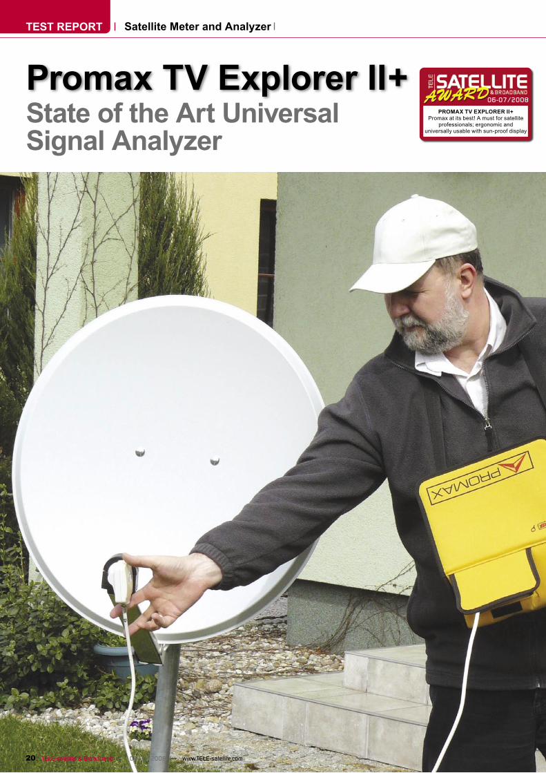
Some people can align their satellite dishes without any extra equipment. Sometimes, they even do it without a signal finder -using only a standard satellite receiver. Of course, this method takes much more time and the alignment may not be as perfect as it could be. Things are not as easy when the antenna is on the roof. In this case you should at least have a simple signal finderalthough this will not be good enough if you are planning to set up and maintain an SMATV network.
same screen: channel power, MER, CBER, VBER, L-band fre-quency, transponder frequency and channel number.
Let’s highlight the features of the TV Explorer II+. It can measure TV and radio signals of all kinds: satellite, terrestrial and cable. It is suitable for FM radio, mobile TV (DVB-H) and for the return channel in cable networks. It works equally well with QPSK, 8PSK, QAM or COFDM modulation. The TV Explorer II+ is really a multi-standard instrument. It accepts any TV system: PAL, SECAM or NTSC and any TV standard: M, N, B, G, I, D, K or L.
The TV Explorer II+ covers a frequency range that is con-tinuous from 5 MHz to 2150 MHz. This covers all terrestrial, cable and satellite ranges. Of course, in the case of satellite transmissions, we are not refer-ring to the downlink frequency from the satellite but rather the output frequency from the LNB (L-band). We can either tune the frequency continuously or jump from transponder to transponder. It comes prepro-grammed with the transpond-ers of many satellites and, of course, this data can be repro-grammed. It measures signals from 44/45 dBµV to 100/114 dBµV depending on the modula-tion type. The measured param-eters, depending on modulation mode, include: power, BER, VBER, LBER, MER, C/N, noise margin and number of wrong packets.
Of course, the analyzer can measure both DVB-S and DVB-S2 signals. All the different FEC
▲
22 TELE-satellite & Broadband — 06-07/2008 — www.TELE-satellite.com
code rates are supported. For DVB-S2 this would be 1/4, 1/3, 2/5, 1/2, 3/5, 2/3, 3/4, 4/5, 5/6, 8/9, 9/10 and Auto for QPSK sig-nals and 3/5, 2/3, 3/4, 5/6, 8/9, 9/10 and Auto for 8PSK signals. If you also deal with analog sig-nals, you’ll be happy to know that you haven’t been left in the dark with the TV Explorer II+. It can measure signal level, C/N, video-audio ratio, FM devia-tion and demodulation (the last two are for classical terrestrial/cable signals).
We can’t emphasize enough the importance of the spec-trum analyzer in this meter. Not only can you examine a signal without knowing any channel frequencies, but you can also detect all the unwanted sig-nals that may be present in a network because of interfer-ence. The frequency span is selectable from 16 MHz to full band and the vertical range is adjustable in steps. Except for measurements, the meter can display the video of a TV signal regardless if it is analog or digital. For digital signals, you can view all free-to-air MPEG-2 channels. It is also possible to receive scrambled channels as long as the proper CAM with smartcard is inserted into the CI slot located on the rear panel of the meter. This is a really unique feature; not many other meters can say they have this. Please note that the meter can not process MPEG-4 streams. In order to view MPEG-4 FTA channels, a suitable MPEG-4 to MPEG-2 conversion module needs to be inserted. However, the meter can measure all DVB-S2 signals even if they carry MPEG-4 streams. The additional module is only required to see the video of a channel.
Everyday UseThe meter was delivered from
Promax in a very large package. We were surprised to discover that so many accessories were included. The box included a very practical carrying bag, a protective suitcase (both with
the shoulder straps), an exter-nal power supply with a power cord, a car power adapter, a USB cable, a 10 dB signal atten-uator, connector adapters and a USB memory stick with PC soft-ware to control the instrument and store the results.
The largest component on the front panel is the 16:9 LCD
display. Underneath there are twelve control buttons. From left to right in the top row the buttons show the video of the channel, set the power for the LNB, show measurement results, show the frequency spectrum, switch between satel-lite/terrestrial mode and switch
between digital/analog mode. In the bottom row from the left the buttons access image and sound properties, DiSEqC com-mands, utilities/setup, antenna alignment mode, transponder or frequency tuning and trans-ponder identification. If you hadany doubts, yes, the TV Explorer II+ can send any DiSEqC com-
mand 1.0, 1.1 or 1.2. The iden-tification of a satellite is basedon the information transmitted from a transponder in the NIT table. If only this information is transmitted (and this depends on the configuration of the pro-vider’s headend), there should be an orbital position and net-
work provider name. So, for example, the Explorer may show us: 13E, ABSat.
Four arrows are used in spec-trum mode to conveniently set the frequency span and the reference level (moving the spectrum up or down). They can also be used when in the menu to travel among differ-ent items and options. The tuning knob is used for moving the marker when in spectrum mode, moving the highlight in the menu or changing the transponder/channel number. Lastly, there are three status LEDs and a luminosity sensor on the front panel. The LED’s indicate that external video (supplied by the Scart connec-tor) is playing on the screen, that an external device (LNB) is powered and that the battery is being charged. The sensor adjusts the brightness and con-trast of the display and helps to conserve battery power. The battery can power the instru-ment for about 4.5 hours con-tinuously. But only 3 hours are needed to charge it to 80%.
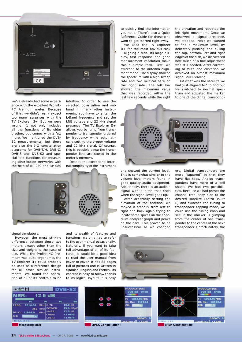
The F connector is situated on the top side panel. Included in the package are suitable con-nector adapters (F to BNC and F to DIN). The power supply socket is located on the right side panel; there’s also a small hole used to reset the unit. We did not have to use the reset feature; the software func-tioned properly throughout the entire test. On the reverse side is the Scart connector. It can be used to send the LCD video and audio to an external moni-tor or TV set or it can accept an incoming video/audio signal for display on the LCD.
The rear panel sports the CI slot for use with a CA module plus there’s also a USB port so that the meter can com-municate with a PC. The whole case is enclosed in protective grey rubber to help protect the meter should it bump into a sat-ellite mast or some other hard surface.
As we mentioned before,
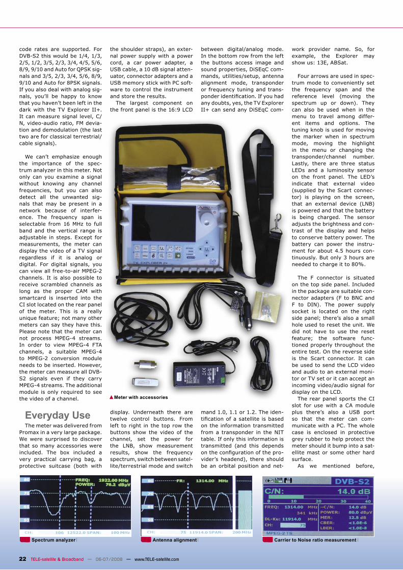
Meter with accessories
Spectrum analyzer Antenna alignment Carrier to Noise ratio measurement
24 TELE-satellite & Broadband — 06-07/2008 — www.TELE-satellite.com
we’ve already had some experi-ence with the excellent Prolink-4C Premium meter. Because of this, we didn’t really expect too many surprises with the TV Explorer II+. But we were wrong! It not only includes all the functions of its older brother, but comes with a few more. We mentioned the DVB-S2 measurements, but there are also the I-Q constellation diagrams for DVB-T/H, DVB-C, DVB-S and DVB-S2 and spe-cial test functions for measur-ing distribution networks with the help of RP-250 and RP-080
signal simulators.However, the most striking
difference between these two meters except other than the size and weight is the ease of use. While the Prolink-4C Pre-mium was quite ergonomic, the TV Explorer II+ could probably be used as a reference design for all other similar instru-ments. We found the opera-tion of all of its controls to be
intuitive. In order to see the selected polarization and sub band in many other instru-ments, you have to enter the L-Band frequency and set the LNB voltage and 22 kHz signal presence. The TV Explorer II+ allows you to jump from trans-ponder to transponder ordered by frequency while automati-cally setting the proper voltage and 22 kHz signal. Of course, this is possible since the trans-ponder lists are stored in the meter’s memory.
Despite the exceptional inter-nal complexity of the instrument
and its wealth of features and functions, we only had to refer to the user manual occasionally. Naturally, if you want to take full advantage of all of its fea-tures, it would be a good idea to read the user manual from cover to cover. It has 85 pages full of pictures and is written in Spanish, English and French. Its content is easy to follow thanks to its logical layout; it is easy
to quickly find the informationyou need. There’s also a Quick Reference Guide for those who want to get started right away.
We used the TV Explorer II+ for the most obvious task – aligning a dish. Its large dis-play, fast response and good measurement resolution make this a simple task. First, we switched to the antenna align-ment mode. The display showed the spectrum with a high sweep rate and two vertical bars on the right side. The left bar showed the maximum value that was recorded within the last few seconds while the right
one showed the current level. This is somewhat similar to the volume level meters found in good quality audio equipment. Additionally, there is an audible signal with a pitch that rises when the signal level goes up.
After arbitrarily setting the elevation of the antenna, we moved it steadily from left to right and back again trying to locate some spikes on the spec-trum analyzer graph and peaks on the bars. This proved to be unsuccessful so we changed
the elevation and repeated the left-right movement. Once we observed a signal presence, we stopped. Next we wanted to find a maximum level. Bydelicately pushing and pulling the top, bottom, left and right edges of the dish, we discovered how much of a fine adjustmentwas still needed. After correct-ing azimuth and elevation we achieved an almost maximum signal level reading.
But what was the satellite we had just aligned to? To find outwe switched to normal spec-trum and adjusted the marker to one of the digital transpond-
ers. Digital transponders are more “squared” in that they have flat tops. Analog trans-ponders have more of a bell shape. We had two possibili-ties. Because we had preset the channel frequency plan to the desired satellite (Astra 19.2° E) and switched the tuning to transponder zapping mode, we could use the tuning knob and see if the marker is jumping from the center of one trans-ponder to the center of the next transponder. Unfortunately, the
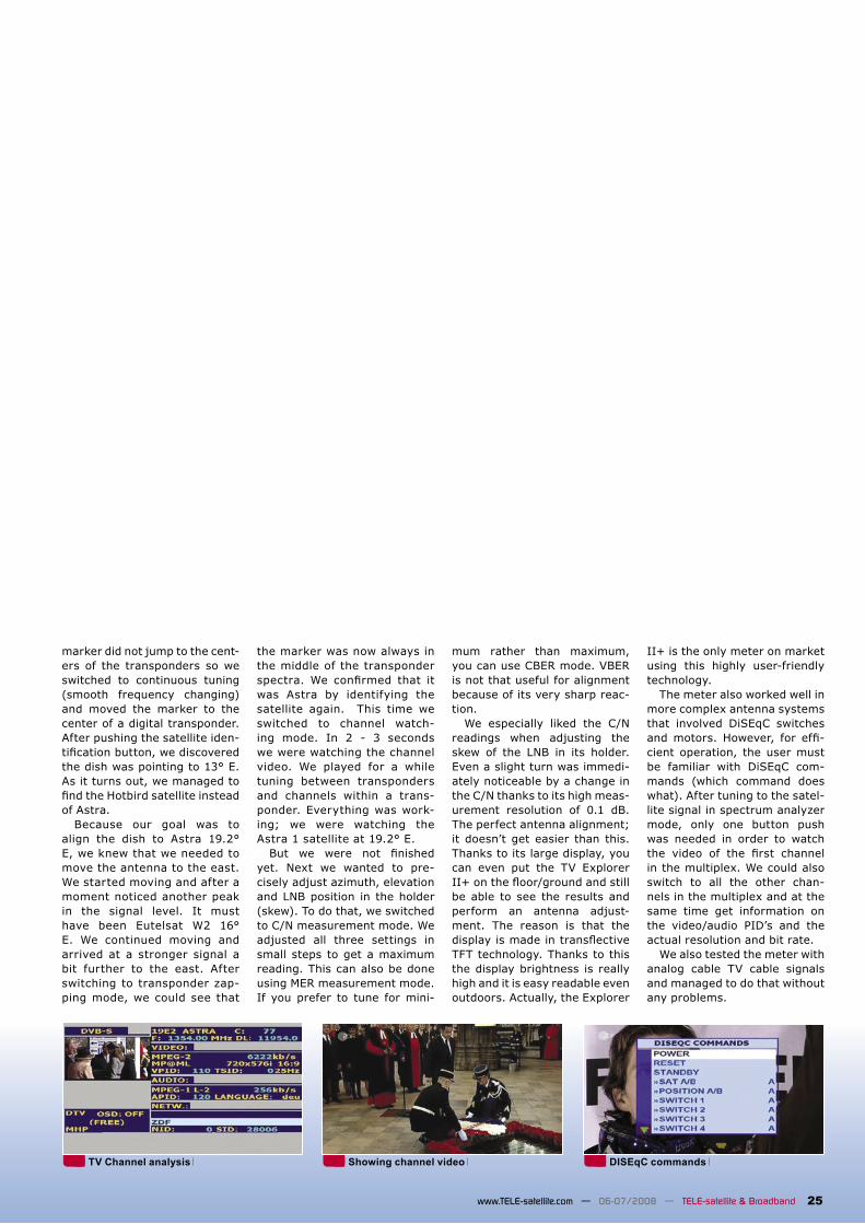
Measuring MER QPSK Constellation 8PSK Constellation
25www.TELE-satellite.com — 06-07/2008 — TELE-satellite & Broadband
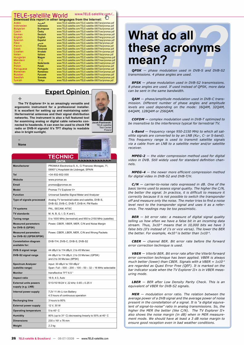
TV Channel analysis Showing channel video DISEqC commands
marker did not jump to the cent-ers of the transponders so we switched to continuous tuning (smooth frequency changing) and moved the marker to the center of a digital transponder. After pushing the satellite iden-tification button, we discoveredthe dish was pointing to 13° E. As it turns out, we managed to find the Hotbird satellite insteadof Astra.
Because our goal was to align the dish to Astra 19.2° E, we knew that we needed to move the antenna to the east. We started moving and after a moment noticed another peak in the signal level. It must have been Eutelsat W2 16° E. We continued moving and arrived at a stronger signal a bit further to the east. After switching to transponder zap-ping mode, we could see that
the marker was now always in the middle of the transponder spectra. We confirmed that itwas Astra by identifying the satellite again. This time we switched to channel watch-ing mode. In 2 - 3 seconds we were watching the channel video. We played for a while tuning between transponders and channels within a trans-ponder. Everything was work-ing; we were watching the Astra 1 satellite at 19.2° E.
But we were not finishedyet. Next we wanted to pre-cisely adjust azimuth, elevation and LNB position in the holder (skew). To do that, we switched to C/N measurement mode. We adjusted all three settings in small steps to get a maximum reading. This can also be done using MER measurement mode. If you prefer to tune for mini-
mum rather than maximum, you can use CBER mode. VBER is not that useful for alignment because of its very sharp reac-tion.
We especially liked the C/N readings when adjusting the skew of the LNB in its holder. Even a slight turn was immedi-ately noticeable by a change in the C/N thanks to its high meas-urement resolution of 0.1 dB. The perfect antenna alignment; it doesn’t get easier than this. Thanks to its large display, you can even put the TV Explorer II+ on the floor/ground and stillbe able to see the results and perform an antenna adjust-ment. The reason is that the display is made in transflectiveTFT technology. Thanks to this the display brightness is really high and it is easy readable even outdoors. Actually, the Explorer
II+ is the only meter on market using this highly user-friendly technology.
The meter also worked well in more complex antenna systems that involved DiSEqC switches and motors. However, for effi-cient operation, the user must be familiar with DiSEqC com-mands (which command does what). After tuning to the satel-lite signal in spectrum analyzer mode, only one button push was needed in order to watch the video of the first channelin the multiplex. We could also switch to all the other chan-nels in the multiplex and at the same time get information on the video/audio PID’s and the actual resolution and bit rate.
We also tested the meter with analog cable TV cable signals and managed to do that without any problems.
DATATECHNIC
TELE-satellite World www.TELE-satellite.com/...
Arabic العربية www.TELE-satellite.com/TELE-satellite-0807/ara/promax.pdfIndonesian Indonesia www.TELE-satellite.com/TELE-satellite-0807/bid/promax.pdfBulgarian Български www.TELE-satellite.com/TELE-satellite-0807/bul/promax.pdfCzech Česky www.TELE-satellite.com/TELE-satellite-0807/ces/promax.pdfGerman Deutsch www.TELE-satellite.com/TELE-satellite-0807/deu/promax.pdfEnglish English www.TELE-satellite.com/TELE-satellite-0807/eng/promax.pdfSpanish Español www.TELE-satellite.com/TELE-satellite-0807/esp/promax.pdfFarsi فارسي www.TELE-satellite.com/TELE-satellite-0807/far/promax.pdfFrench Français www.TELE-satellite.com/TELE-satellite-0807/fra/promax.pdfGreek Ελληνικά www.TELE-satellite.com/TELE-satellite-0807/hel/promax.pdfCroatian Hrvatski www.TELE-satellite.com/TELE-satellite-0807/hrv/promax.pdfItalian Italiano www.TELE-satellite.com/TELE-satellite-0807/ita/promax.pdfHungarian Magyar www.TELE-satellite.com/TELE-satellite-0807/mag/promax.pdfMandarin 中文 www.TELE-satellite.com/TELE-satellite-0807/man/promax.pdfDutch Nederlands www.TELE-satellite.com/TELE-satellite-0807/ned/promax.pdfPolish Polski www.TELE-satellite.com/TELE-satellite-0807/pol/promax.pdfPortuguese Português www.TELE-satellite.com/TELE-satellite-0807/por/promax.pdfRomanian Românesc www.TELE-satellite.com/TELE-satellite-0807/rom/promax.pdfRussian Русский www.TELE-satellite.com/TELE-satellite-0807/rus/promax.pdfSwedish Svenska www.TELE-satellite.com/TELE-satellite-0807/sve/promax.pdfTurkish Türkçe www.TELE-satellite.com/TELE-satellite-0807/tur/promax.pdf
???
26 TELE-satellite & Broadband — 06-07/2008 — www.TELE-satellite.com
Manufacturer PROMAX Electronica S. A., C/ Francesc Moragas, 71, 08907 L’Hospitalet de Llobregat, SPAIN
Tel +34-932-602-000
Website www.promax.es
Email [email protected]
Model Promax TV Explorer II+
Function Universal Satellite Signal Meter and Analyzer
Type of signals processed Analog TV terrestrial/cable and satellite, DVB-S, DVB-S2, DVB-C, DVB-T, DVB-H, FM Radio
TV systems PAL, SECAM, NTSC
TV standards M, N, B, G, I, D, K and L
Tuning range 5 to 1000 MHz (terrestrial) and 950 to 2150 MHz (satellite)
Measured parameters Power, CBER, VBER, MER, C/N and Noise Marginfor DVB-S (QPSK)
Measured parameters Power, CBER, LBER, MER, C/N and Wrong Packetsfor DVB-S2 (QPSK/8PSK)
Constellation diagram DVB-T/H, DVB-C, DVB-S, DVB-S2available for:
DVB-S signal range 44 dBµV to 114 dBµV, 2 to 45 Ms/sec
DVB-S2 signal range 44 dBµV to 114 dBµV, 2 to 33 Ms/sec (QPSK) and 2 to 30 Ms/sec (8PSK)
Spectrum Analyzer Input: 30 dBµV to 130 dBµV(satellite range) Span: Full – 500 – 200 – 100 – 50 – 32 – 16 MHz selectable
Monitor transflective TFT 6.5 “
Aspect ratio 16:9, 4:3, Auto
External units powers 5/13/15/18/24 V, 22 kHz: 0.65 ± 0.25 Vsupply (e.g. LNB)
Internal power supply 7.2V 11 Ah Li-ion Battery 4.5 hours of continuous operation
Recharging time 3 hours to 80%
External power supply 12 V, 30 W
Operating temperature 5 to 40° C
Humidity 80% (up to 31° C) decreasing linearly to 50% at 40° C
Dimensions 230 x 161 x 76 mm
Weight 2.2 kg
Expert Opinion+The TV Explorer II+ is an amazingly versatile and
ergonomic instrument for a professional installer. It is excellent for setting up and maintaining satel-lite/terrestrial antennas and their signal distribution networks. The instrument is also a full featured tool for examining analog or digital cable networks con-nected to headends. It can even be used to check FM radio or DVB-H signals! It’s TFT display is readable also in bright sunlight.
-None
Jacek PawlowskiTELE-satellite
Test CenterPoland
Download this report in other languages from the Internet:
What do all these acronyms mean?QPSK ― phase modulation used in DVB-S and DVB-S2
transmissions. 4 phase angles are used.
8PSK ― phase modulation used in DVB-S2 transmissions. 8 phase angles are used. If used instead of QPSK, more data can be sent in the same bandwidth.
QAM ― phase/amplitude modulation used in DVB-C trans-mission. Different number of phase angles and amplitude levels are used depending on the mode: 16QAM, 32QAM, 64QAM, 128QAM or 256QAM.
COFDM ― complex modulation used in DVB-T optimized to be insensitive to the interference typical for terrestrial TV.
L-Band ― frequency range 950-2150 MHz to which all sat-ellite signals are converted to by an LNB (Ku-, C- or S-band). This frequency range is used to transmit satellite signals via a cable from an LNB to a satellite meter and/or satellite receiver.
MPEG-2 ― the older compression method used for digital video in DVB. Still widely used for standard definition chan-nels.
MPEG-4 ― the newer more efficient compression methodfor digital video in DVB-S2 and DVB-T/H.
C/N ― carrier-to-noise ratio expressed in dB. One of the basic terms used to assess signal quality. The higher the C/N, the better the signal. In practice, it is difficult to measure itcorrectly because it is not possible to switch the transponder off and measure only the noise. The meter tries to find a noiselevel next to the transponder signal and uses it as a refer-ence. The readings may be too pessimistic.
BER ― bit error rate: a measure of digital signal quality telling us how often we have a false bit in an incoming data stream. Thus, 3x10⁻⁴ means that in 10,000 bits we have 3 false bits (0’s instead of 1’s or vice versa). The lower the BER the better. For example, 4x10⁻⁵ is better than 1x10⁻⁴.
CBER ― channel BER. Bit error rate before the forward error correction technique is used.
VBER ― Viterbi BER. Bit error rate after the Viterbi forward error correction technique has been applied. VBER is always much better (lower) than CBER. Signals with a VBER = 1x10⁻⁴ are regarded as Quasi Error Free (QEF). It is marked on the bar indicator scale when the TV Explorer II+ is in VBER meas-uring mode.
LBER ― BER after Low Density Parity Check. This is an equivalent of VBER for DVB-S2 signals.
MER ― modulation error ratio. The relation between the average power of a DVB signal and the average power of noise present in the constellation of a signal. It is “a digital equiva-lent of signal-to-noise” ratio in analog transmissions. So, the higher the MER the better (like C/N). The TV Explorer II+ also shows the noise margin (in dB) when in MER measure-ment mode. We should have at least a 3 dB noise margin to ensure good reception even in bad weather conditions.