Embed Size (px)
Citation preview

Products Solutions Services
Operating InstructionsProline Promag W 300HARTElectromagnetic flowmeter
Keep cover
h
tig
t while
Spannung
öffn
en
BA01918D/06/EN/01.19714245972019-02-01
Valid as of version01.01.zz (Device firmware)

Proline Promag W 300 HART
2 Endress+Hauser
• Make sure the document is stored in a safe place such that it is always available whenworking on or with the device.
• To avoid danger to individuals or the facility, read the "Basic safety instructions" sectioncarefully, as well as all other safety instructions in the document that are specific toworking procedures.
• The manufacturer reserves the right to modify technical data without prior notice. YourEndress+Hauser Sales Center will supply you with current information and updates tothese instructions.
Proline Promag W 300 HART Table of contents
Endress+Hauser 3
Table of contents
1 About this document . . . . . . . . . . . . . . . . 61.1 Document function . . . . . . . . . . . . . . . . . . . . . 61.2 Symbols used . . . . . . . . . . . . . . . . . . . . . . . . . . 6
1.2.1 Safety symbols . . . . . . . . . . . . . . . . . . 61.2.2 Electrical symbols . . . . . . . . . . . . . . . . 61.2.3 Communication symbols . . . . . . . . . . . 61.2.4 Tool symbols . . . . . . . . . . . . . . . . . . . . 71.2.5 Symbols for
certain types of information . . . . . . . . . 71.2.6 Symbols in graphics . . . . . . . . . . . . . . . 7
1.3 Documentation . . . . . . . . . . . . . . . . . . . . . . . . 81.3.1 Standard documentation . . . . . . . . . . . 81.3.2 Supplementary device-dependent
documentation . . . . . . . . . . . . . . . . . . 81.4 Registered trademarks . . . . . . . . . . . . . . . . . . . 8
2 Basic safety instructions . . . . . . . . . . . . 92.1 Requirements for the personnel . . . . . . . . . . . . 92.2 Designated use . . . . . . . . . . . . . . . . . . . . . . . . 92.3 Workplace safety . . . . . . . . . . . . . . . . . . . . . . 102.4 Operational safety . . . . . . . . . . . . . . . . . . . . . 102.5 Product safety . . . . . . . . . . . . . . . . . . . . . . . . 102.6 IT security . . . . . . . . . . . . . . . . . . . . . . . . . . . 112.7 Device-specific IT security . . . . . . . . . . . . . . . . 11
2.7.1 Protecting access via hardware writeprotection . . . . . . . . . . . . . . . . . . . . . 11
2.7.2 Protecting access via a password . . . . 112.7.3 Access via Web server . . . . . . . . . . . . 122.7.4 Access via OPC-UA . . . . . . . . . . . . . . 132.7.5 Access via service interface (CDI-
RJ45) . . . . . . . . . . . . . . . . . . . . . . . . 13
3 Product description . . . . . . . . . . . . . . . . 143.1 Product design . . . . . . . . . . . . . . . . . . . . . . . . 14
4 Incoming acceptance and productidentification . . . . . . . . . . . . . . . . . . . . . 15
4.1 Incoming acceptance . . . . . . . . . . . . . . . . . . . 154.2 Product identification . . . . . . . . . . . . . . . . . . . 15
4.2.1 Transmitter nameplate . . . . . . . . . . . 164.2.2 Sensor nameplate . . . . . . . . . . . . . . . 174.2.3 Symbols on measuring device . . . . . . 17
5 Storage and transport . . . . . . . . . . . . . 185.1 Storage conditions . . . . . . . . . . . . . . . . . . . . . 185.2 Transporting the product . . . . . . . . . . . . . . . . 18
5.2.1 Measuring devices without liftinglugs . . . . . . . . . . . . . . . . . . . . . . . . . 18
5.2.2 Measuring devices with lifting lugs . . 195.2.3 Transporting with a fork lift . . . . . . . . 19
5.3 Packaging disposal . . . . . . . . . . . . . . . . . . . . . 19
6 Installation . . . . . . . . . . . . . . . . . . . . . . . 206.1 Installation conditions . . . . . . . . . . . . . . . . . . 20
6.1.1 Mounting position . . . . . . . . . . . . . . . 206.1.2 Environment and process
requirements . . . . . . . . . . . . . . . . . . 236.1.3 Special mounting instructions . . . . . . 25
6.2 Mounting the measuring device . . . . . . . . . . . 256.2.1 Required tools . . . . . . . . . . . . . . . . . . 256.2.2 Preparing the measuring device . . . . . 256.2.3 Mounting the sensor . . . . . . . . . . . . . 256.2.4 Turning the transmitter housing . . . . 326.2.5 Turning the display module . . . . . . . . 32
6.3 Post-installation check . . . . . . . . . . . . . . . . . . 33
7 Electrical connection . . . . . . . . . . . . . . 347.1 Connection conditions . . . . . . . . . . . . . . . . . . 34
7.1.1 Required tools . . . . . . . . . . . . . . . . . . 347.1.2 Requirements for connecting cable . . . 347.1.3 Terminal assignment . . . . . . . . . . . . . 377.1.4 Preparing the measuring device . . . . . 37
7.2 Connecting the measuring device . . . . . . . . . . 377.2.1 Connecting the transmitter . . . . . . . . 377.2.2 Connecting the remote display and
operating module DKX001 . . . . . . . . 407.3 Ensuring potential equalization . . . . . . . . . . . 40
7.3.1 Requirements . . . . . . . . . . . . . . . . . . 407.3.2 Connection example, standard
scenario . . . . . . . . . . . . . . . . . . . . . . 407.3.3 Connection example in special
situations . . . . . . . . . . . . . . . . . . . . . 417.4 Special connection instructions . . . . . . . . . . . . 42
7.4.1 Connection examples . . . . . . . . . . . . . 427.5 Ensuring the degree of protection . . . . . . . . . . 467.6 Post-connection check . . . . . . . . . . . . . . . . . . 47
8 Operation options . . . . . . . . . . . . . . . . . 488.1 Overview of operation options . . . . . . . . . . . . 488.2 Structure and function of the operating
menu . . . . . . . . . . . . . . . . . . . . . . . . . . . . . . 498.2.1 Structure of the operating menu . . . . 498.2.2 Operating philosophy . . . . . . . . . . . . 50
8.3 Access to the operating menu via the localdisplay . . . . . . . . . . . . . . . . . . . . . . . . . . . . . 518.3.1 Operational display . . . . . . . . . . . . . . 518.3.2 Navigation view . . . . . . . . . . . . . . . . 528.3.3 Editing view . . . . . . . . . . . . . . . . . . . 548.3.4 Operating elements . . . . . . . . . . . . . . 568.3.5 Opening the context menu . . . . . . . . . 568.3.6 Navigating and selecting from list . . . 588.3.7 Calling the parameter directly . . . . . . 588.3.8 Calling up help text . . . . . . . . . . . . . . 598.3.9 Changing the parameters . . . . . . . . . 598.3.10 User roles and related access
authorization . . . . . . . . . . . . . . . . . . 60
Table of contents Proline Promag W 300 HART
4 Endress+Hauser
8.3.11 Disabling write protection via accesscode . . . . . . . . . . . . . . . . . . . . . . . . . 60
8.3.12 Enabling and disabling the keypadlock . . . . . . . . . . . . . . . . . . . . . . . . . 61
8.4 Access to the operating menu via the Webbrowser . . . . . . . . . . . . . . . . . . . . . . . . . . . . . 618.4.1 Function range . . . . . . . . . . . . . . . . . 618.4.2 Prerequisites . . . . . . . . . . . . . . . . . . . 628.4.3 Establishing a connection . . . . . . . . . 638.4.4 Logging on . . . . . . . . . . . . . . . . . . . . 658.4.5 User interface . . . . . . . . . . . . . . . . . . 668.4.6 Disabling the Web server . . . . . . . . . . 678.4.7 Logging out . . . . . . . . . . . . . . . . . . . . 67
8.5 Access to the operating menu via theoperating tool . . . . . . . . . . . . . . . . . . . . . . . . 688.5.1 Connecting the operating tool . . . . . . 688.5.2 Field Xpert SFX350, SFX370 . . . . . . . 718.5.3 FieldCare . . . . . . . . . . . . . . . . . . . . . 718.5.4 DeviceCare . . . . . . . . . . . . . . . . . . . . 738.5.5 AMS Device Manager . . . . . . . . . . . . 738.5.6 SIMATIC PDM . . . . . . . . . . . . . . . . . . 748.5.7 Field Communicator 475 . . . . . . . . . . 74
9 System integration . . . . . . . . . . . . . . . . 759.1 Overview of device description files . . . . . . . . . 75
9.1.1 Current version data for the device . . . 759.1.2 Operating tools . . . . . . . . . . . . . . . . . 75
9.2 Measured variables via HART protocol . . . . . . 759.3 Other settings . . . . . . . . . . . . . . . . . . . . . . . . 77
10 Commissioning . . . . . . . . . . . . . . . . . . . . 7910.1 Function check . . . . . . . . . . . . . . . . . . . . . . . 7910.2 Switching on the measuring device . . . . . . . . . 7910.3 Setting the operating language . . . . . . . . . . . . 7910.4 Configuring the measuring device . . . . . . . . . . 79
10.4.1 Defining the tag name . . . . . . . . . . . . 8110.4.2 Setting the system units . . . . . . . . . . 8110.4.3 Displaying the I/O configuration . . . . 8210.4.4 Configuring the status input . . . . . . . 8310.4.5 Configuring the current input . . . . . . 8410.4.6 Configuring the current output . . . . . 8510.4.7 Configuring the pulse/frequency/
switch output . . . . . . . . . . . . . . . . . . 8810.4.8 Configuring the local display . . . . . . . 9410.4.9 Configuring the low flow cut off . . . . . 9510.4.10 Configuring empty pipe detection . . . 9710.4.11 Configuring the HART input . . . . . . . 9710.4.12 Configuring the relay output . . . . . . . 9910.4.13 Configuring the double pulse output 101
10.5 Advanced settings . . . . . . . . . . . . . . . . . . . . 10310.5.1 Using the parameter to enter the
access code . . . . . . . . . . . . . . . . . . . 10410.5.2 Carrying out a sensor adjustment . . . 10410.5.3 Configuring the totalizer . . . . . . . . . 10410.5.4 Carrying out additional display
configurations . . . . . . . . . . . . . . . . . 10610.5.5 Performing electrode cleaning . . . . . 10910.5.6 WLAN configuration . . . . . . . . . . . . 109
10.5.7 Configuration management . . . . . . . 11110.5.8 Using parameters for device
administration . . . . . . . . . . . . . . . . 11210.6 Simulation . . . . . . . . . . . . . . . . . . . . . . . . . . 11410.7 Protecting settings from unauthorized
access . . . . . . . . . . . . . . . . . . . . . . . . . . . . . 11610.7.1 Write protection via access code . . . 11710.7.2 Write protection via write protection
switch . . . . . . . . . . . . . . . . . . . . . . . 118
11 Operation . . . . . . . . . . . . . . . . . . . . . . . 12011.1 Reading the device locking status . . . . . . . . . 12011.2 Adjusting the operating language . . . . . . . . . 12011.3 Configuring the display . . . . . . . . . . . . . . . . 12011.4 Reading measured values . . . . . . . . . . . . . . . 120
11.4.1 "Process variables" submenu . . . . . . . 12011.4.2 "Totalizer" submenu . . . . . . . . . . . . . 12111.4.3 "Input values" submenu . . . . . . . . . . 12211.4.4 Output values . . . . . . . . . . . . . . . . . 123
11.5 Adapting the measuring device to the processconditions . . . . . . . . . . . . . . . . . . . . . . . . . . 125
11.6 Performing a totalizer reset . . . . . . . . . . . . . 12511.6.1 Function scope of the "Control
Totalizer" parameter . . . . . . . . . . . . 12611.6.2 Function scope of the "Reset all
totalizers" parameter . . . . . . . . . . . . 12611.7 Showing data logging . . . . . . . . . . . . . . . . . 126
12 Diagnostics and troubleshooting . . 13012.1 General troubleshooting . . . . . . . . . . . . . . . . 13012.2 Diagnostic information via light emitting
diodes . . . . . . . . . . . . . . . . . . . . . . . . . . . . . 13212.2.1 Transmitter . . . . . . . . . . . . . . . . . . . 132
12.3 Diagnostic information on local display . . . . . 13412.3.1 Diagnostic message . . . . . . . . . . . . . 13412.3.2 Calling up remedial measures . . . . . 136
12.4 Diagnostic information in the Web browser . 13612.4.1 Diagnostic options . . . . . . . . . . . . . . 13612.4.2 Calling up remedy information . . . . 137
12.5 Diagnostic information in FieldCare orDeviceCare . . . . . . . . . . . . . . . . . . . . . . . . . 13812.5.1 Diagnostic options . . . . . . . . . . . . . . 13812.5.2 Calling up remedy information . . . . 139
12.6 Adapting the diagnostic information . . . . . . 13912.6.1 Adapting the diagnostic behavior . . . 13912.6.2 Adapting the status signal . . . . . . . . 139
12.7 Overview of diagnostic information . . . . . . . 14012.8 Pending diagnostic events . . . . . . . . . . . . . . 14412.9 Diagnostic list . . . . . . . . . . . . . . . . . . . . . . . 14512.10 Event logbook . . . . . . . . . . . . . . . . . . . . . . . 145
12.10.1 Reading out the event logbook . . . . . 14512.10.2 Filtering the event logbook . . . . . . . 14612.10.3 Overview of information events . . . . 146
12.11 Resetting the measuring device . . . . . . . . . . 14812.11.1 Function scope of the "Device reset"
parameter . . . . . . . . . . . . . . . . . . . . 14812.12 Device information . . . . . . . . . . . . . . . . . . . 14812.13 Firmware history . . . . . . . . . . . . . . . . . . . . . 151
Proline Promag W 300 HART Table of contents
Endress+Hauser 5
13 Maintenance . . . . . . . . . . . . . . . . . . . . 15213.1 Maintenance tasks . . . . . . . . . . . . . . . . . . . . 152
13.1.1 Exterior cleaning . . . . . . . . . . . . . . . 15213.1.2 Interior cleaning . . . . . . . . . . . . . . . 15213.1.3 Replacing seals . . . . . . . . . . . . . . . . 152
13.2 Measuring and test equipment . . . . . . . . . . . 15213.3 Endress+Hauser services . . . . . . . . . . . . . . . 152
14 Repair . . . . . . . . . . . . . . . . . . . . . . . . . . . 15314.1 General notes . . . . . . . . . . . . . . . . . . . . . . . 153
14.1.1 Repair and conversion concept . . . . . 15314.1.2 Notes for repair and conversion . . . . 153
14.2 Spare parts . . . . . . . . . . . . . . . . . . . . . . . . . 15314.3 Endress+Hauser services . . . . . . . . . . . . . . . 15314.4 Return . . . . . . . . . . . . . . . . . . . . . . . . . . . . . 15314.5 Disposal . . . . . . . . . . . . . . . . . . . . . . . . . . . 154
14.5.1 Removing the measuring device . . . . 15414.5.2 Disposing of the measuring device . . 154
15 Accessories . . . . . . . . . . . . . . . . . . . . . . 15515.1 Device-specific accessories . . . . . . . . . . . . . . 155
15.1.1 For the transmitter . . . . . . . . . . . . . 15515.1.2 For the sensor . . . . . . . . . . . . . . . . . 156
15.2 Communication-specific accessories . . . . . . . 15615.3 Service-specific accessories . . . . . . . . . . . . . . 15715.4 System components . . . . . . . . . . . . . . . . . . . 157
16 Technical data . . . . . . . . . . . . . . . . . . . 15816.1 Application . . . . . . . . . . . . . . . . . . . . . . . . . 15816.2 Function and system design . . . . . . . . . . . . . 15816.3 Input . . . . . . . . . . . . . . . . . . . . . . . . . . . . . . 15816.4 Output . . . . . . . . . . . . . . . . . . . . . . . . . . . . 16416.5 Power supply . . . . . . . . . . . . . . . . . . . . . . . . 16816.6 Performance characteristics . . . . . . . . . . . . . 16916.7 Installation . . . . . . . . . . . . . . . . . . . . . . . . . 17116.8 Environment . . . . . . . . . . . . . . . . . . . . . . . . 17116.9 Process . . . . . . . . . . . . . . . . . . . . . . . . . . . . 17216.10 Mechanical construction . . . . . . . . . . . . . . . 17516.11 Operability . . . . . . . . . . . . . . . . . . . . . . . . . 18416.12 Certificates and approvals . . . . . . . . . . . . . . 18816.13 Application packages . . . . . . . . . . . . . . . . . . 18916.14 Accessories . . . . . . . . . . . . . . . . . . . . . . . . . 19016.15 Supplementary documentation . . . . . . . . . . . 191
Index . . . . . . . . . . . . . . . . . . . . . . . . . . . . . . . . . 193
About this document Proline Promag W 300 HART
6 Endress+Hauser
1 About this document
1.1 Document functionThese Operating Instructions contain all the information that is required in various phasesof the life cycle of the device: from product identification, incoming acceptance andstorage, to mounting, connection, operation and commissioning through totroubleshooting, maintenance and disposal.
1.2 Symbols used
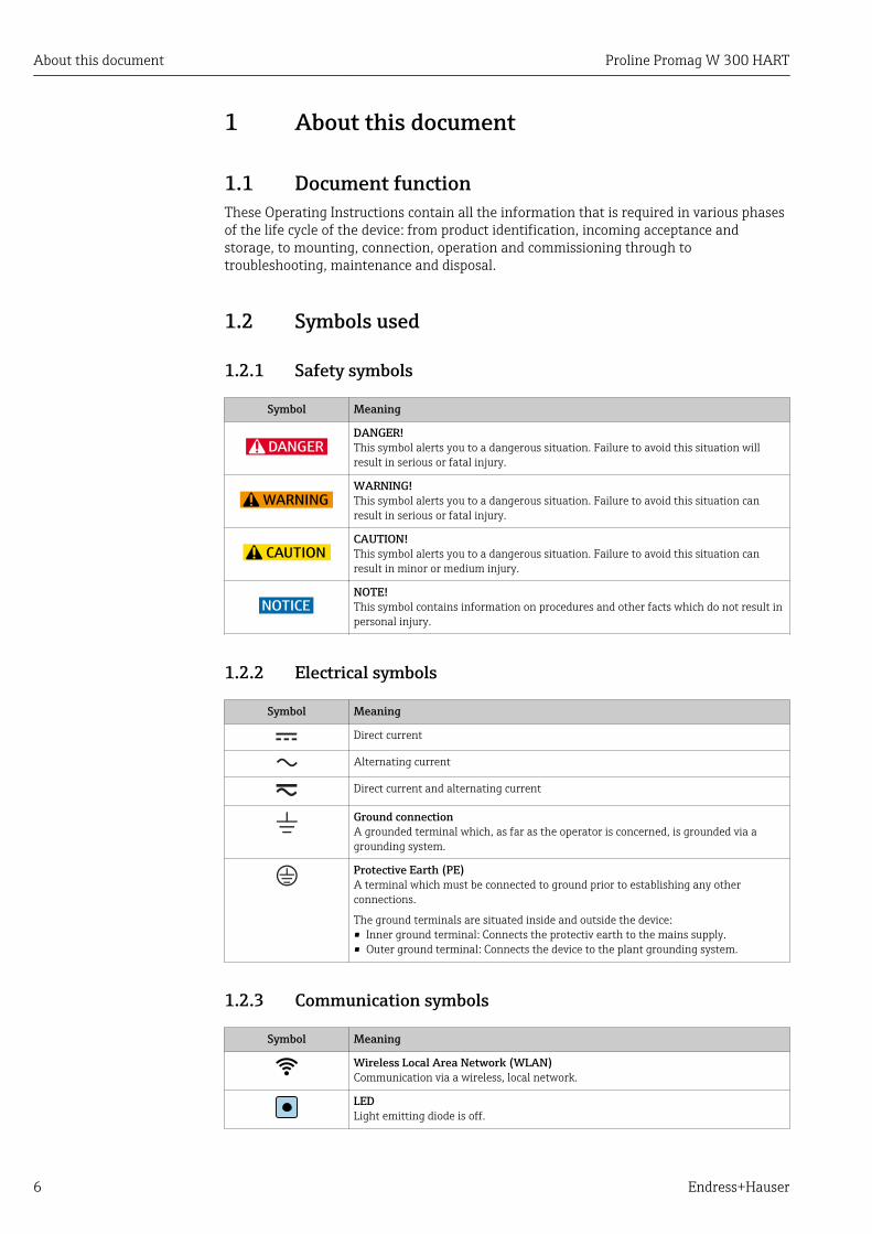
1.2.1 Safety symbols
Symbol Meaning
DANGER
DANGER!This symbol alerts you to a dangerous situation. Failure to avoid this situation willresult in serious or fatal injury.
WARNING
WARNING!This symbol alerts you to a dangerous situation. Failure to avoid this situation canresult in serious or fatal injury.
CAUTION
CAUTION!This symbol alerts you to a dangerous situation. Failure to avoid this situation canresult in minor or medium injury.
NOTICE
NOTE!This symbol contains information on procedures and other facts which do not result inpersonal injury.
1.2.2 Electrical symbols
Symbol Meaning
Direct current
Alternating current
Direct current and alternating current
Ground connectionA grounded terminal which, as far as the operator is concerned, is grounded via agrounding system.
Protective Earth (PE)A terminal which must be connected to ground prior to establishing any otherconnections.
The ground terminals are situated inside and outside the device:• Inner ground terminal: Connects the protectiv earth to the mains supply.• Outer ground terminal: Connects the device to the plant grounding system.
1.2.3 Communication symbols
Symbol Meaning
Wireless Local Area Network (WLAN)Communication via a wireless, local network.
LEDLight emitting diode is off.
Proline Promag W 300 HART About this document
Endress+Hauser 7
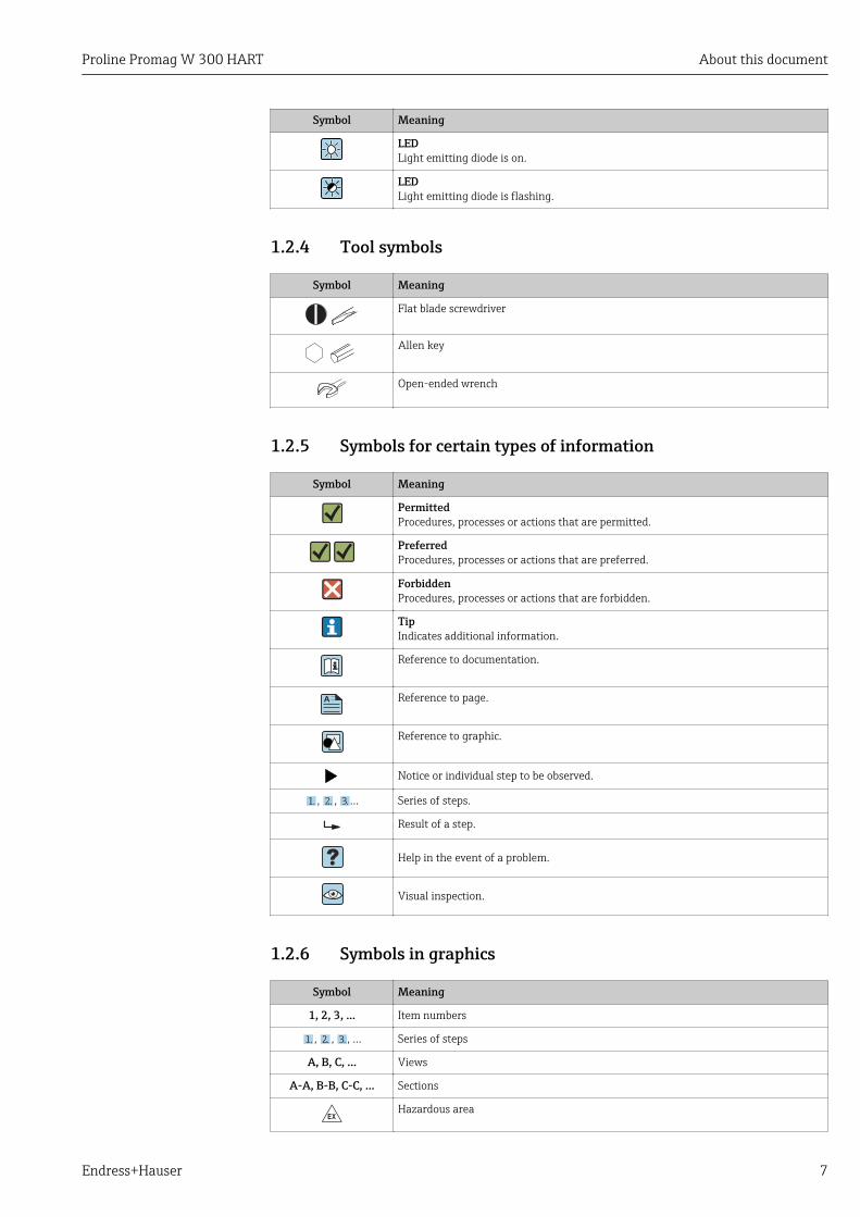
Symbol Meaning
LEDLight emitting diode is on.
LEDLight emitting diode is flashing.
1.2.4 Tool symbols
Symbol Meaning
Flat blade screwdriver
Allen key
Open-ended wrench
1.2.5 Symbols for certain types of information
Symbol Meaning
PermittedProcedures, processes or actions that are permitted.
PreferredProcedures, processes or actions that are preferred.
ForbiddenProcedures, processes or actions that are forbidden.
TipIndicates additional information.
Reference to documentation.
A Reference to page.
Reference to graphic.
Notice or individual step to be observed.
1. , 2. , 3.… Series of steps.
Result of a step.
Help in the event of a problem.
Visual inspection.
1.2.6 Symbols in graphics
Symbol Meaning
1, 2, 3, ... Item numbers
1. , 2. , 3. , … Series of steps
A, B, C, ... Views
A-A, B-B, C-C, ... Sections
-Hazardous area
About this document Proline Promag W 300 HART
8 Endress+Hauser
Symbol Meaning
.Safe area (non-hazardous area)
Flow direction
1.3 DocumentationFor an overview of the scope of the associated Technical Documentation, refer to thefollowing:• W@M Device Viewer (www.endress.com/deviceviewer): Enter the serial number
from nameplate• Endress+Hauser Operations App: Enter the serial number from the nameplate or
scan the 2D matrix code (QR code) on the nameplate
Detailed list of the individual documents along with the documentation code→ 191
1.3.1 Standard documentation
Document type Purpose and content of the document
Technical Information Planning aid for your deviceThe document contains all the technical data on the device and providesan overview of the accessories and other products that can be ordered forthe device.
Sensor Brief Operating Instructions Guides you quickly to the 1st measured value - Part 1The Sensor Brief Operating Instructions are aimed at specialists withresponsibility for installing the measuring device.
• Incoming acceptance and product identification• Storage and transport• Installation
Transmitter Brief OperatingInstructions
Guides you quickly to the 1st measured value - Part 2The Transmitter Brief Operating Instructions are aimed at specialists withresponsibility for commissioning, configuring and parameterizing themeasuring device (until the first measured value).
• Product description• Installation• Electrical connection• Operation options• System integration• Commissioning• Diagnostic information
Description of Device Parameters Reference for your parametersThe document provides a detailed explanation of each individualparameter in the Expert operating menu. The description is aimed atthose who work with the device over the entire life cycle and performspecific configurations.
1.3.2 Supplementary device-dependent documentationAdditional documents are supplied depending on the device version ordered: Alwayscomply strictly with the instructions in the supplementary documentation. Thesupplementary documentation is an integral part of the device documentation.
1.4 Registered trademarksHART®Registered trademark of the FieldComm Group, Austin, Texas, USA
Proline Promag W 300 HART Basic safety instructions
Endress+Hauser 9
2 Basic safety instructions
2.1 Requirements for the personnelThe personnel for installation, commissioning, diagnostics and maintenance must fulfillthe following requirements:‣ Trained, qualified specialists must have a relevant qualification for this specific function
and task.‣ Are authorized by the plant owner/operator.‣ Are familiar with federal/national regulations.‣ Before starting work, read and understand the instructions in the manual and
supplementary documentation as well as the certificates (depending on theapplication).
‣ Follow instructions and comply with basic conditions.
The operating personnel must fulfill the following requirements:‣ Are instructed and authorized according to the requirements of the task by the facility's
owner-operator.‣ Follow the instructions in this manual.
2.2 Designated useApplication and mediaThe measuring device described in these Brief Operating Instructions is intended only forflow measurement of liquids with a minimum conductivity of 5 µS/cm.
Depending on the version ordered, the measuring device can also measure potentiallyexplosive, flammable, poisonous and oxidizing media.
Measuring devices for use in hazardous areas, in hygienic applications or where there is anincreased risk due to process pressure, are labeled accordingly on the nameplate.
To ensure that the measuring device remains in proper condition for the operation time:‣ Keep within the specified pressure and temperature range.‣ Only use the measuring device in full compliance with the data on the nameplate and
the general conditions listed in the Operating Instructions and supplementarydocumentation.
‣ Based on the nameplate, check whether the ordered device is permitted for theintended use in the hazardous area (e.g. explosion protection, pressure vessel safety).
‣ Use the measuring device only for media to which the process-wetted materials aresufficiently resistant.
‣ If the ambient temperature of the measuring device is outside the atmospherictemperature, it is absolutely essential to comply with the relevant basic conditions asspecified in the device documentation. → 8
‣ Protect the measuring device permanently against corrosion from environmentalinfluences.
Incorrect useNon-designated use can compromise safety. The manufacturer is not liable for damagecaused by improper or non-designated use.
LWARNINGDanger of breakage due to corrosive or abrasive fluids and ambient conditions!‣ Verify the compatibility of the process fluid with the sensor material.‣ Ensure the resistance of all fluid-wetted materials in the process.‣ Keep within the specified pressure and temperature range.

Basic safety instructions Proline Promag W 300 HART
10 Endress+Hauser
NOTICEVerification for borderline cases:‣ For special fluids and fluids for cleaning, Endress+Hauser is glad to provide assistance
in verifying the corrosion resistance of fluid-wetted materials, but does not accept anywarranty or liability as minute changes in the temperature, concentration or level ofcontamination in the process can alter the corrosion resistance properties.
Residual risks
LWARNINGThe electronics and the medium may cause the surfaces to heat up. This presents aburn hazard!‣ For elevated fluid temperatures, ensure protection against contact to prevent burns.
2.3 Workplace safetyFor work on and with the device:‣ Wear the required personal protective equipment according to federal/national
regulations.
For welding work on the piping:‣ Do not ground the welding unit via the measuring device.
If working on and with the device with wet hands:‣ Due to the increased risk of electric shock, gloves must be worn.
2.4 Operational safetyRisk of injury.‣ Operate the device in proper technical condition and fail-safe condition only.‣ The operator is responsible for interference-free operation of the device.
Conversions to the deviceUnauthorized modifications to the device are not permitted and can lead to unforeseeabledangers.‣ If, despite this, modifications are required, consult with Endress+Hauser.
RepairTo ensure continued operational safety and reliability,‣ Carry out repairs on the device only if they are expressly permitted.‣ Observe federal/national regulations pertaining to repair of an electrical device.‣ Use original spare parts and accessories from Endress+Hauser only.
2.5 Product safetyThis measuring device is designed in accordance with good engineering practice to meetstate-of-the-art safety requirements, has been tested, and left the factory in a condition inwhich it is safe to operate.
It meets general safety standards and legal requirements. It also complies with the EUdirectives listed in the device-specific EU Declaration of Conformity. Endress+Hauserconfirms this by affixing the CE mark to the device.

Proline Promag W 300 HART Basic safety instructions
Endress+Hauser 11
2.6 IT securityOur warranty is valid only if the device is installed and used as described in the OperatingInstructions. The device is equipped with security mechanisms to protect it against anyinadvertent changes to the settings.
IT security measures, which provide additional protection for the device and associateddata transfer, must be implemented by the operators themselves in line with their securitystandards.
2.7 Device-specific IT securityThe device offers a range of specific functions to support protective measures on theoperator's side. These functions can be configured by the user and guarantee greater in-operation safety if used correctly. An overview of the most important functions is providedin the following section.
Function/interface Factory setting Recommendation
Write protection via hardware writeprotection switch → 11
Not enabled. On an individual basis following riskassessment.
Access code(also applies for Web server login orFieldCare connection) → 12
Not enabled(0000).
Assign a customized access code duringcommissioning.
WLAN(order option in display module)
Enabled. On an individual basis following riskassessment.
WLAN security mode Enabled (WPA2-PSK)
Do not change.
WLAN passphrase(password) → 12
Serial number Assign an individual WLAN passphrase duringcommissioning.
WLAN mode Access Point On an individual basis following riskassessment.
Web server→ 12 Enabled. On an individual basis following riskassessment.
CDI-RJ45 service interface → 13 – On an individual basis following riskassessment.
2.7.1 Protecting access via hardware write protectionWrite access to the device parameters via the local display, Web browser or operating tool(e.g. FieldCare, DeviceCare) can be disabled via a write protection switch (DIP switch onthe motherboard). When hardware write protection is enabled, only read access to theparameters is possible.
Hardware write protection is disabled when the device is delivered → 118.
2.7.2 Protecting access via a passwordDifferent passwords are available to protect write access to the device parameters or accessto the device via the WLAN interface.
Basic safety instructions Proline Promag W 300 HART
12 Endress+Hauser
• User-specific access codeProtect write access to the device parameters via the local display, Web browser oroperating tool (e.g. FieldCare, DeviceCare). Access authorization is clearly regulatedthrough the use of a user-specific access code.
• WLAN passphraseThe network key protects a connection between an operating unit (e.g. notebook ortablet) and the device via the WLAN interface which can be ordered as an option.
• Infrastructure modeWhen the device is operated in infrastructure mode, the WLAN passphrase correspondsto the WLAN passphrase configured on the operator side.
User-specific access codeWrite access to the device parameters via the local display, Web browser or operating tool(e.g. FieldCare, DeviceCare) can be protected by the modifiable, user-specific access code(→ 117).
When the device is delivered, the device does not have an access code and is equivalent to0000 (open).
WLAN passphrase: Operation as WLAN access pointA connection between an operating unit (e.g. notebook or tablet) and the device via theWLAN interface (→ 70), which can be ordered as an optional extra, is protected bythe network key. The WLAN authentication of the network key complies with theIEEE 802.11 standard.
When the device is delivered, the network key is pre-defined depending on the device. Itcan be changed via the WLAN settings submenu in the WLAN passphrase parameter(→ 110).
Infrastructure modeA connection between the device and WLAN access point is protected by means of an SSIDand passphrase on the system side. Please contact the relevant system administrator foraccess.
General notes on the use of passwords• The access code and network key supplied with the device should be changed during
commissioning.• Follow the general rules for generating a secure password when defining and managing
the access code or network key.• The user is responsible for the management and careful handling of the access code and
network key.• For information on configuring the access code or on what to do if you lose the
password, see the "Write protection via access code" section → 117
2.7.3 Access via Web serverThe device can be operated and configured via a Web browser with the integrated Webserver (→ 61). The connection is via the service interface (CDI-RJ45) or the WLANinterface.
The Web server is enabled when the device is delivered. The Web server can be disabled ifnecessary (e.g. after commissioning) via the Web server functionality parameter.
The device and status information can be hidden on the login page. This preventsunauthorized access to the information.
For detailed information on device parameters, see:The "Description of Device Parameters" document → 191.
Proline Promag W 300 HART Basic safety instructions
Endress+Hauser 13
2.7.4 Access via OPC-UAThe device can communicate with OPC UA clients using the "OPC UA Server" applicationpackage.
The OPC UA server integrated in the device can be accessed via the WLAN access pointusing the WLAN interface - which can be ordered as an optional extra - or the serviceinterface (CDI- RJ45) via Ethernet network. Access rights and authorization as perseparate configuration.
The following Security Modes are supported as per the OPC UA Specification (IEC 62541):• None• Basic128Rsa15 – signed• Basic128Rsa15 – signed and encrypted
2.7.5 Access via service interface (CDI-RJ45)The device can be connected to a network via the service interface (CDI-RJ45). Device-specific functions guarantee the secure operation of the device in a network.
The use of relevant industrial standards and guidelines that have been defined by nationaland international safety committees, such as IEC/ISA62443 or the IEEE, is recommended.This includes organizational security measures such as the assignment of accessauthorization as well as technical measures such as network segmentation.

Product description Proline Promag W 300 HART
14 Endress+Hauser
3 Product descriptionThe device consists of a transmitter and a sensor.
The device is available as a compact version:The transmitter and sensor form a mechanical unit.
3.1 Product design
5
4
Nicht unter
Spannung öffnen
Do not open when
energizedNe pas ouvrir
sous tension
Power
I/O
Nic
ht
unte
r
ar
e
öffn
en
Disp
lay
+
E
ESC
–
1 2 3
A0029586
1 Important components of a measuring device
1 Connection compartment cover2 Display module3 Transmitter housing4 Electronics compartment cover5 Sensor
Proline Promag W 300 HART Incoming acceptance and product identification
Endress+Hauser 15
4 Incoming acceptance and productidentification
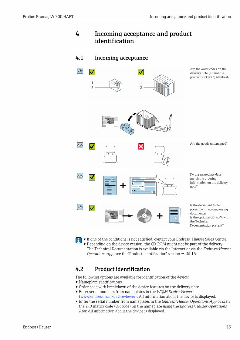
4.1 Incoming acceptance
1
2
1
2
Are the order codes on thedelivery note (1) and theproduct sticker (2) identical?
Are the goods undamaged?
Order code:
Ser. no.:
Ext. ord. cd.:
i i
Date:
Do the nameplate datamatch the orderinginformation on the deliverynote?
Is the document folderpresent with accompanyingdocuments?Is the optional CD-ROM withthe TechnicalDocumentation present?
• If one of the conditions is not satisfied, contact your Endress+Hauser Sales Center.• Depending on the device version, the CD-ROM might not be part of the delivery!
The Technical Documentation is available via the Internet or via the Endress+HauserOperations App, see the "Product identification" section → 16.
4.2 Product identificationThe following options are available for identification of the device:• Nameplate specifications• Order code with breakdown of the device features on the delivery note• Enter serial numbers from nameplates in the W@M Device Viewer
(www.endress.com/deviceviewer): All information about the device is displayed.• Enter the serial number from nameplates in the Endress+Hauser Operations App or scan
the 2-D matrix code (QR code) on the nameplate using the Endress+Hauser OperationsApp: All information about the device is displayed.
Incoming acceptance and product identification Proline Promag W 300 HART
16 Endress+Hauser
For an overview of the scope of the associated Technical Documentation, refer to thefollowing:• The "Additional standard documentation on the device"→ 8 and "Supplementary
device-dependent documentation"→ 8 sections• The W@M Device Viewer: enter the serial number from the nameplate
(www.endress.com/deviceviewer)• The Endress+Hauser Operations App: Enter the serial number from the nameplate or
scan the 2-D matrix code (QR code) on the nameplate.
4.2.1 Transmitter nameplate
Order code:
Ser. no.:
Ext. ord. cd.:
i i
Date:
1 2 3 4 5
20
19
6
7
8
9
13 12 1011
18
17
16
14
15
A0029192
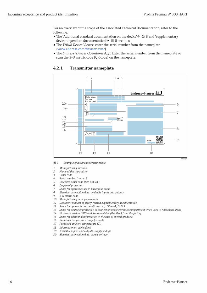
2 Example of a transmitter nameplate
1 Manufacturing location2 Name of the transmitter3 Order code4 Serial number (ser. no.)5 Extended order code (Ext. ord. cd.)6 Degree of protection7 Space for approvals: use in hazardous areas8 Electrical connection data: available inputs and outputs9 2-D matrix code10 Manufacturing date: year-month11 Document number of safety-related supplementary documentation12 Space for approvals and certificates: e.g. CE mark, C-Tick13 Space for degree of protection of connection and electronics compartment when used in hazardous areas14 Firmware version (FW) and device revision (Dev.Rev.) from the factory15 Space for additional information in the case of special products16 Permitted temperature range for cable17 Permitted ambient temperature (Ta)18 Information on cable gland19 Available inputs and outputs, supply voltage20 Electrical connection data: supply voltage

Proline Promag W 300 HART Incoming acceptance and product identification
Endress+Hauser 17
4.2.2 Sensor nameplateOrder codeThe measuring device is reordered using the order code.
Extended order code• The device type (product root) and basic specifications (mandatory features) are
always listed.• Of the optional specifications (optional features), only the safety and approval-
related specifications are listed (e.g. LA). If other optional specifications are alsoordered, these are indicated collectively using the # placeholder symbol (e.g. #LA#).
• If the ordered optional specifications do not include any safety and approval-relatedspecifications, they are indicated by the + placeholder symbol (e.g. XXXXXX-ABCDE+).
4.2.3 Symbols on measuring device
Symbol Meaning
WARNING!This symbol alerts you to a dangerous situation. Failure to avoid this situation can result in seriousor fatal injury.
Reference to documentationRefers to the corresponding device documentation.
Protective ground connectionA terminal which must be connected to ground prior to establishing any other connections.
Storage and transport Proline Promag W 300 HART
18 Endress+Hauser
5 Storage and transport
5.1 Storage conditionsObserve the following notes for storage:‣ Store in the original packaging to ensure protection from shock.‣ Do not remove protective covers or protective caps installed on process connections.
They prevent mechanical damage to the sealing surfaces and contamination in themeasuring tube.
‣ Protect from direct sunlight to avoid unacceptably high surface temperatures.‣ Select a storage location where moisture cannot collect in the measuring device as
fungus and bacteria infestation can damage the lining.‣ Store in a dry and dust-free place.‣ Do not store outdoors.
Storage temperature→ 171
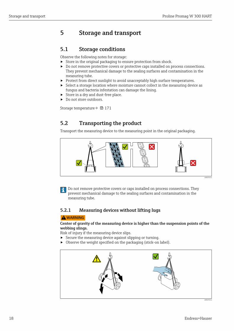
5.2 Transporting the productTransport the measuring device to the measuring point in the original packaging.
A0029252
Do not remove protective covers or caps installed on process connections. Theyprevent mechanical damage to the sealing surfaces and contamination in themeasuring tube.
5.2.1 Measuring devices without lifting lugsLWARNING
Center of gravity of the measuring device is higher than the suspension points of thewebbing slings.Risk of injury if the measuring device slips.‣ Secure the measuring device against slipping or turning.‣ Observe the weight specified on the packaging (stick-on label).
A0029214
Proline Promag W 300 HART Storage and transport
Endress+Hauser 19
5.2.2 Measuring devices with lifting lugsLCAUTION
Special transportation instructions for devices with lifting lugs‣ Only use the lifting lugs fitted on the device or flanges to transport the device.‣ The device must always be secured at two lifting lugs at least.
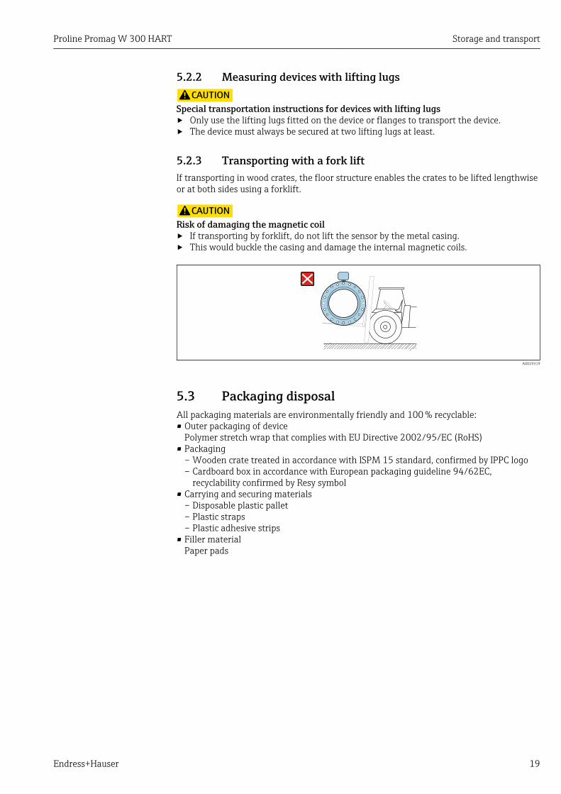
5.2.3 Transporting with a fork liftIf transporting in wood crates, the floor structure enables the crates to be lifted lengthwiseor at both sides using a forklift.
LCAUTIONRisk of damaging the magnetic coil‣ If transporting by forklift, do not lift the sensor by the metal casing.‣ This would buckle the casing and damage the internal magnetic coils.
A0029319
5.3 Packaging disposalAll packaging materials are environmentally friendly and 100 % recyclable:• Outer packaging of device
Polymer stretch wrap that complies with EU Directive 2002/95/EC (RoHS)• Packaging
– Wooden crate treated in accordance with ISPM 15 standard, confirmed by IPPC logo– Cardboard box in accordance with European packaging guideline 94/62EC,
recyclability confirmed by Resy symbol• Carrying and securing materials
– Disposable plastic pallet– Plastic straps– Plastic adhesive strips
• Filler materialPaper pads
Installation Proline Promag W 300 HART
20 Endress+Hauser
6 Installation
6.1 Installation conditions
6.1.1 Mounting position
Mounting location
h
A0029343
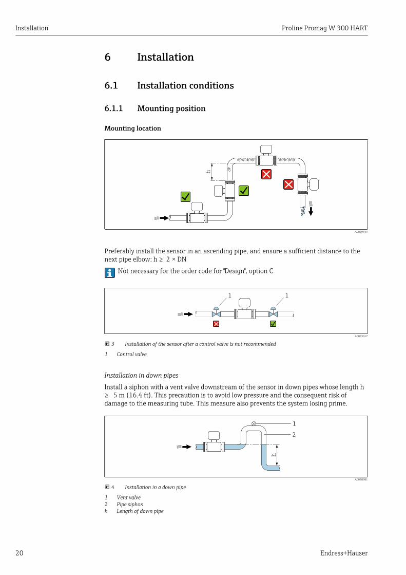
Preferably install the sensor in an ascending pipe, and ensure a sufficient distance to thenext pipe elbow: h ≥ 2 × DN
Not necessary for the order code for "Design", option C
1 1
A0033017
3 Installation of the sensor after a control valve is not recommended
1 Control valve
Installation in down pipes
Install a siphon with a vent valve downstream of the sensor in down pipes whose length h≥ 5 m (16.4 ft). This precaution is to avoid low pressure and the consequent risk ofdamage to the measuring tube. This measure also prevents the system losing prime.
h
2
1
A0028981
4 Installation in a down pipe
1 Vent valve2 Pipe siphonh Length of down pipe
Proline Promag W 300 HART Installation
Endress+Hauser 21
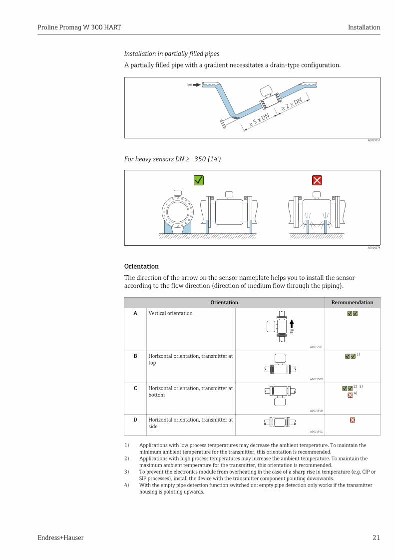
Installation in partially filled pipes
A partially filled pipe with a gradient necessitates a drain-type configuration.
2 x DN
³
5 x DN
³
A0029257
For heavy sensors DN ≥ 350 (14")
A0016276
OrientationThe direction of the arrow on the sensor nameplate helps you to install the sensoraccording to the flow direction (direction of medium flow through the piping).
Orientation Recommendation
A Vertical orientation
A0015591
B Horizontal orientation, transmitter attop
A0015589
1)
C Horizontal orientation, transmitter atbottom
A0015590
2) 3)
4)
D Horizontal orientation, transmitter atside
A0015592
1) Applications with low process temperatures may decrease the ambient temperature. To maintain theminimum ambient temperature for the transmitter, this orientation is recommended.
2) Applications with high process temperatures may increase the ambient temperature. To maintain themaximum ambient temperature for the transmitter, this orientation is recommended.
3) To prevent the electronics module from overheating in the case of a sharp rise in temperature (e.g. CIP orSIP processes), install the device with the transmitter component pointing downwards.
4) With the empty pipe detection function switched on: empty pipe detection only works if the transmitterhousing is pointing upwards.
Installation Proline Promag W 300 HART
22 Endress+Hauser
Horizontal
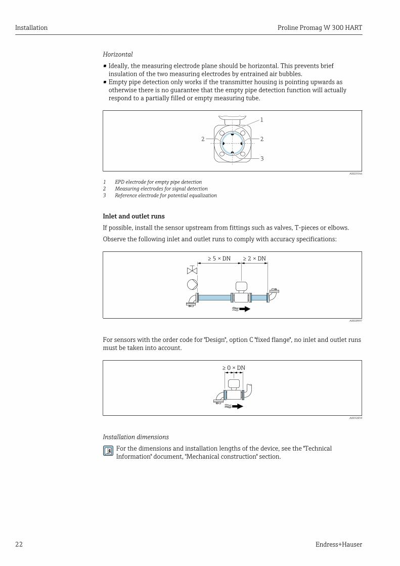
• Ideally, the measuring electrode plane should be horizontal. This prevents briefinsulation of the two measuring electrodes by entrained air bubbles.
• Empty pipe detection only works if the transmitter housing is pointing upwards asotherwise there is no guarantee that the empty pipe detection function will actuallyrespond to a partially filled or empty measuring tube.
1
2
3
2
A0029344
1 EPD electrode for empty pipe detection2 Measuring electrodes for signal detection3 Reference electrode for potential equalization
Inlet and outlet runsIf possible, install the sensor upstream from fittings such as valves, T-pieces or elbows.
Observe the following inlet and outlet runs to comply with accuracy specifications:
≥ 5 × DN ≥ 2 × DN
A0028997
For sensors with the order code for "Design", option C "fixed flange", no inlet and outlet runsmust be taken into account.
≥ 0 × DN
A0032859
Installation dimensions
For the dimensions and installation lengths of the device, see the "TechnicalInformation" document, "Mechanical construction" section.
Proline Promag W 300 HART Installation
Endress+Hauser 23
6.1.2 Environment and process requirements
Ambient temperature range
Transmitter Standard: –40 to +60 °C (–40 to +140 °F)
Local display –20 to +60 °C (–4 to +140 °F), the readability of the display may beimpaired at temperatures outside the temperature range.
Sensor • Process connection material, carbon steel:–10 to +60 °C (+14 to +140 °F)
• Process connection material, stainless steel:–40 to +60 °C (–40 to +140 °F)
Liner Do not exceed or fall below the permitted temperature range of the liner .
If operating outdoors:• Install the measuring device in a shady location.• Avoid direct sunlight, particularly in warm climatic regions.• Avoid direct exposure to weather conditions.
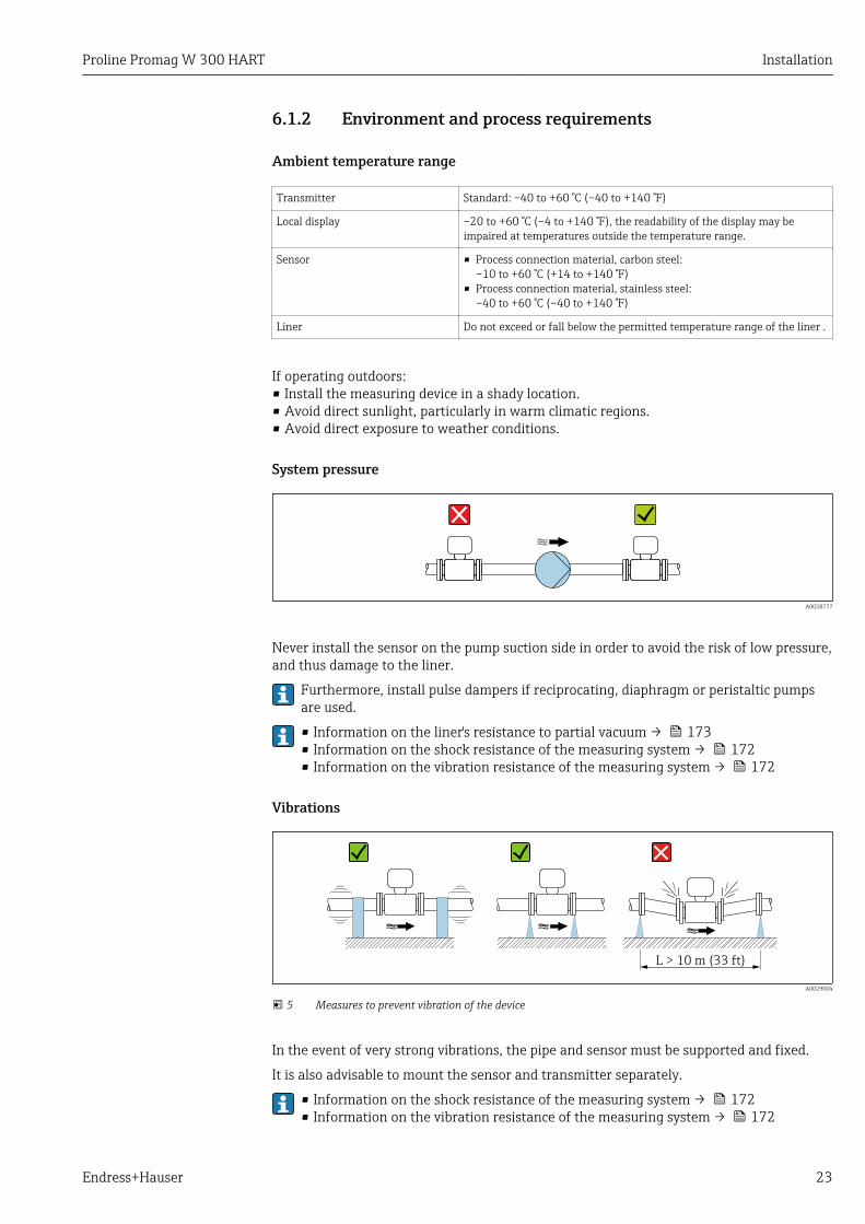
System pressure
A0028777
Never install the sensor on the pump suction side in order to avoid the risk of low pressure,and thus damage to the liner.
Furthermore, install pulse dampers if reciprocating, diaphragm or peristaltic pumpsare used.
• Information on the liner's resistance to partial vacuum → 173• Information on the shock resistance of the measuring system → 172• Information on the vibration resistance of the measuring system → 172
Vibrations
L > 10 m (33 ft)
A0029004
5 Measures to prevent vibration of the device
In the event of very strong vibrations, the pipe and sensor must be supported and fixed.
It is also advisable to mount the sensor and transmitter separately.
• Information on the shock resistance of the measuring system → 172• Information on the vibration resistance of the measuring system → 172
Installation Proline Promag W 300 HART
24 Endress+Hauser
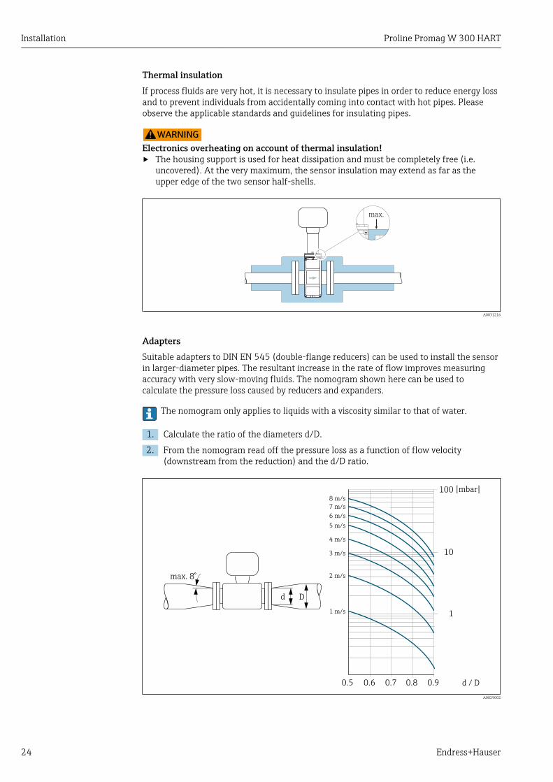
Thermal insulationIf process fluids are very hot, it is necessary to insulate pipes in order to reduce energy lossand to prevent individuals from accidentally coming into contact with hot pipes. Pleaseobserve the applicable standards and guidelines for insulating pipes.
LWARNINGElectronics overheating on account of thermal insulation!‣ The housing support is used for heat dissipation and must be completely free (i.e.
uncovered). At the very maximum, the sensor insulation may extend as far as theupper edge of the two sensor half-shells.
max.
A0031216
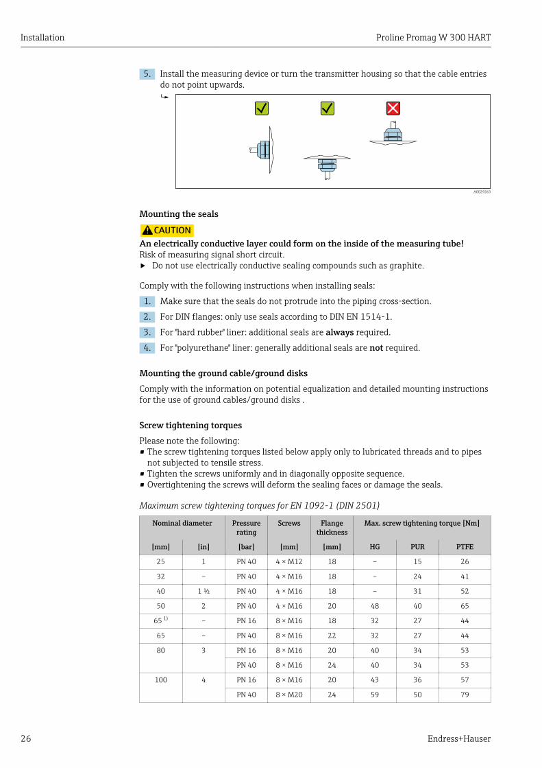
AdaptersSuitable adapters to DIN EN 545 (double-flange reducers) can be used to install the sensorin larger-diameter pipes. The resultant increase in the rate of flow improves measuringaccuracy with very slow-moving fluids. The nomogram shown here can be used tocalculate the pressure loss caused by reducers and expanders.
The nomogram only applies to liquids with a viscosity similar to that of water.
1. Calculate the ratio of the diameters d/D.
2. From the nomogram read off the pressure loss as a function of flow velocity(downstream from the reduction) and the d/D ratio.
100
10
0.5 d / D
[mbar]
0.6 0.7 0.8 0.9
1 m/s
2 m/s
3 m/s
4 m/s
5 m/s
6 m/s
7 m/s
8 m/s
1
Dd
max. 8°
A0029002

Proline Promag W 300 HART Installation
Endress+Hauser 25
6.1.3 Special mounting instructions
Protective cover
146 (5.75)
48
(1
.9)
12 (0.47)
280 (11.0) 255 (10.0)
134 (5.3) 30 (1.18)
A0029553
6.2 Mounting the measuring device
6.2.1 Required tools
For sensorFor flanges and other process connections: Corresponding mounting tools
6.2.2 Preparing the measuring device1. Remove all remaining transport packaging.
2. Remove any protective covers or protective caps present from the sensor.
3. Remove stick-on label on the electronics compartment cover.
6.2.3 Mounting the sensorLWARNING
Danger due to improper process sealing!‣ Ensure that the inside diameters of the gaskets are greater than or equal to that of the
process connections and piping.‣ Ensure that the gaskets are clean and undamaged.‣ Install the gaskets correctly.
1. Ensure that the direction of the arrow on the sensor matches the flow direction ofthe medium.
2. To ensure compliance with device specifications, install the measuring devicebetween the pipe flanges in a way that it is centered in the measurement section.
3. If using ground disks, comply with the Installation Instructions provided.
4. Observe required screw tightening torques .
Installation Proline Promag W 300 HART
26 Endress+Hauser
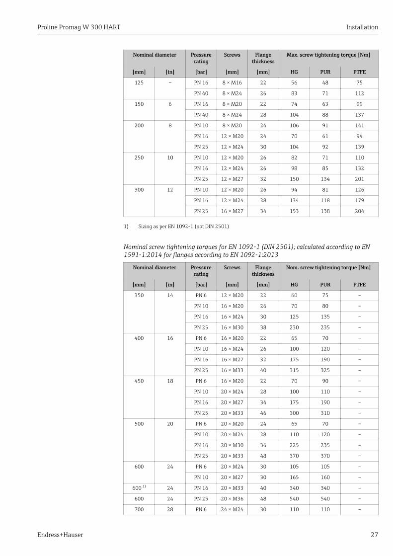
5. Install the measuring device or turn the transmitter housing so that the cable entriesdo not point upwards.
A0029263
Mounting the seals
LCAUTIONAn electrically conductive layer could form on the inside of the measuring tube!Risk of measuring signal short circuit.‣ Do not use electrically conductive sealing compounds such as graphite.
Comply with the following instructions when installing seals:
1. Make sure that the seals do not protrude into the piping cross-section.
2. For DIN flanges: only use seals according to DIN EN 1514-1.
3. For "hard rubber" liner: additional seals are always required.
4. For "polyurethane" liner: generally additional seals are not required.
Mounting the ground cable/ground disksComply with the information on potential equalization and detailed mounting instructionsfor the use of ground cables/ground disks .
Screw tightening torquesPlease note the following:• The screw tightening torques listed below apply only to lubricated threads and to pipes
not subjected to tensile stress.• Tighten the screws uniformly and in diagonally opposite sequence.• Overtightening the screws will deform the sealing faces or damage the seals.
Maximum screw tightening torques for EN 1092-1 (DIN 2501)
Nominal diameter Pressurerating
Screws Flangethickness
Max. screw tightening torque [Nm]
[mm] [in] [bar] [mm] [mm] HG PUR PTFE
25 1 PN 40 4 × M12 18 – 15 26
32 – PN 40 4 × M16 18 – 24 41
40 1 ½ PN 40 4 × M16 18 – 31 52
50 2 PN 40 4 × M16 20 48 40 65
65 1) – PN 16 8 × M16 18 32 27 44
65 – PN 40 8 × M16 22 32 27 44
80 3 PN 16 8 × M16 20 40 34 53
PN 40 8 × M16 24 40 34 53
100 4 PN 16 8 × M16 20 43 36 57
PN 40 8 × M20 24 59 50 79
Proline Promag W 300 HART Installation
Endress+Hauser 27
Nominal diameter Pressurerating
Screws Flangethickness
Max. screw tightening torque [Nm]
[mm] [in] [bar] [mm] [mm] HG PUR PTFE
125 – PN 16 8 × M16 22 56 48 75
PN 40 8 × M24 26 83 71 112
150 6 PN 16 8 × M20 22 74 63 99
PN 40 8 × M24 28 104 88 137
200 8 PN 10 8 × M20 24 106 91 141
PN 16 12 × M20 24 70 61 94
PN 25 12 × M24 30 104 92 139
250 10 PN 10 12 × M20 26 82 71 110
PN 16 12 × M24 26 98 85 132
PN 25 12 × M27 32 150 134 201
300 12 PN 10 12 × M20 26 94 81 126
PN 16 12 × M24 28 134 118 179
PN 25 16 × M27 34 153 138 204
1) Sizing as per EN 1092-1 (not DIN 2501)
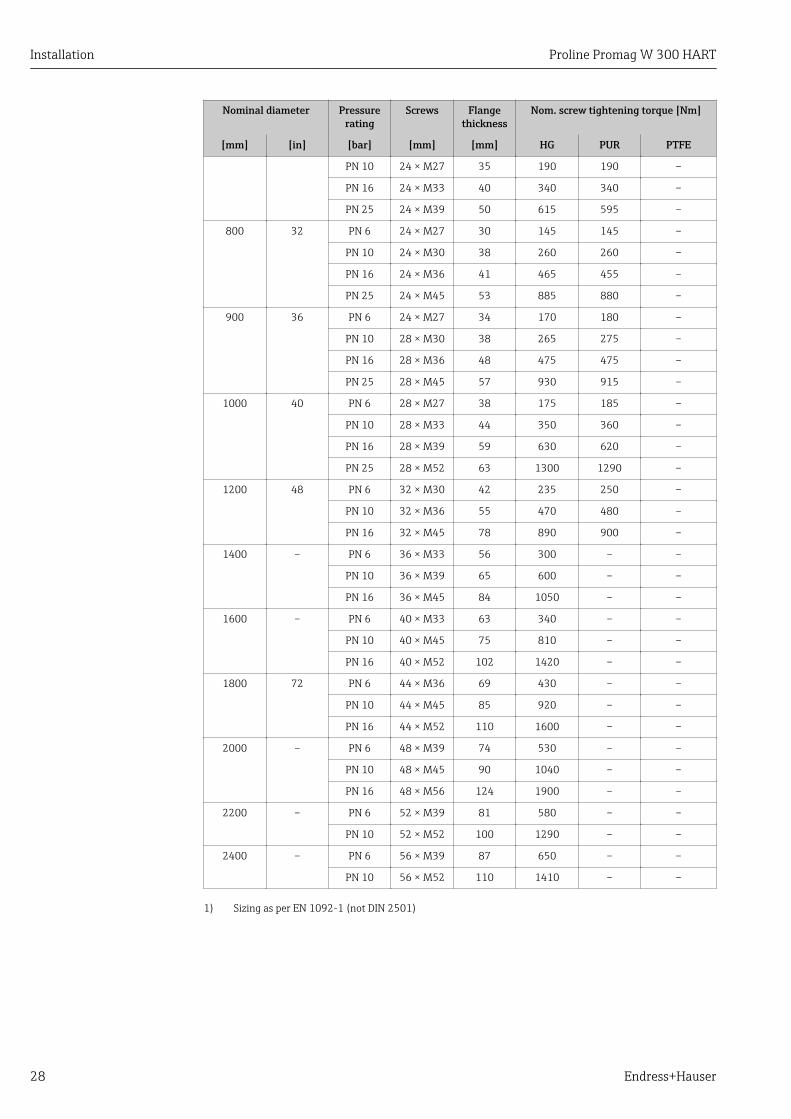
Nominal screw tightening torques for EN 1092-1 (DIN 2501); calculated according to EN1591-1:2014 for flanges according to EN 1092-1:2013
Nominal diameter Pressurerating
Screws Flangethickness
Nom. screw tightening torque [Nm]
[mm] [in] [bar] [mm] [mm] HG PUR PTFE
350 14 PN 6 12 × M20 22 60 75 –
PN 10 16 × M20 26 70 80 –
PN 16 16 × M24 30 125 135 –
PN 25 16 × M30 38 230 235 –
400 16 PN 6 16 × M20 22 65 70 –
PN 10 16 × M24 26 100 120 –
PN 16 16 × M27 32 175 190 –
PN 25 16 × M33 40 315 325 –
450 18 PN 6 16 × M20 22 70 90 –
PN 10 20 × M24 28 100 110 –
PN 16 20 × M27 34 175 190 –
PN 25 20 × M33 46 300 310 –
500 20 PN 6 20 × M20 24 65 70 –
PN 10 20 × M24 28 110 120 –
PN 16 20 × M30 36 225 235 –
PN 25 20 × M33 48 370 370 –
600 24 PN 6 20 × M24 30 105 105 –
PN 10 20 × M27 30 165 160 –
600 1) 24 PN 16 20 × M33 40 340 340 –
600 24 PN 25 20 × M36 48 540 540 –
700 28 PN 6 24 × M24 30 110 110 –
Installation Proline Promag W 300 HART
28 Endress+Hauser
Nominal diameter Pressurerating
Screws Flangethickness
Nom. screw tightening torque [Nm]
[mm] [in] [bar] [mm] [mm] HG PUR PTFE
PN 10 24 × M27 35 190 190 –
PN 16 24 × M33 40 340 340 –
PN 25 24 × M39 50 615 595 –
800 32 PN 6 24 × M27 30 145 145 –
PN 10 24 × M30 38 260 260 –
PN 16 24 × M36 41 465 455 –
PN 25 24 × M45 53 885 880 –
900 36 PN 6 24 × M27 34 170 180 –
PN 10 28 × M30 38 265 275 –
PN 16 28 × M36 48 475 475 –
PN 25 28 × M45 57 930 915 –
1000 40 PN 6 28 × M27 38 175 185 –
PN 10 28 × M33 44 350 360 –
PN 16 28 × M39 59 630 620 –
PN 25 28 × M52 63 1300 1290 –
1200 48 PN 6 32 × M30 42 235 250 –
PN 10 32 × M36 55 470 480 –
PN 16 32 × M45 78 890 900 –
1400 – PN 6 36 × M33 56 300 – –
PN 10 36 × M39 65 600 – –
PN 16 36 × M45 84 1050 – –
1600 – PN 6 40 × M33 63 340 – –
PN 10 40 × M45 75 810 – –
PN 16 40 × M52 102 1420 – –
1800 72 PN 6 44 × M36 69 430 – –
PN 10 44 × M45 85 920 – –
PN 16 44 × M52 110 1600 – –
2000 – PN 6 48 × M39 74 530 – –
PN 10 48 × M45 90 1040 – –
PN 16 48 × M56 124 1900 – –
2200 – PN 6 52 × M39 81 580 – –
PN 10 52 × M52 100 1290 – –
2400 – PN 6 56 × M39 87 650 – –
PN 10 56 × M52 110 1410 – –
1) Sizing as per EN 1092-1 (not DIN 2501)
Proline Promag W 300 HART Installation
Endress+Hauser 29
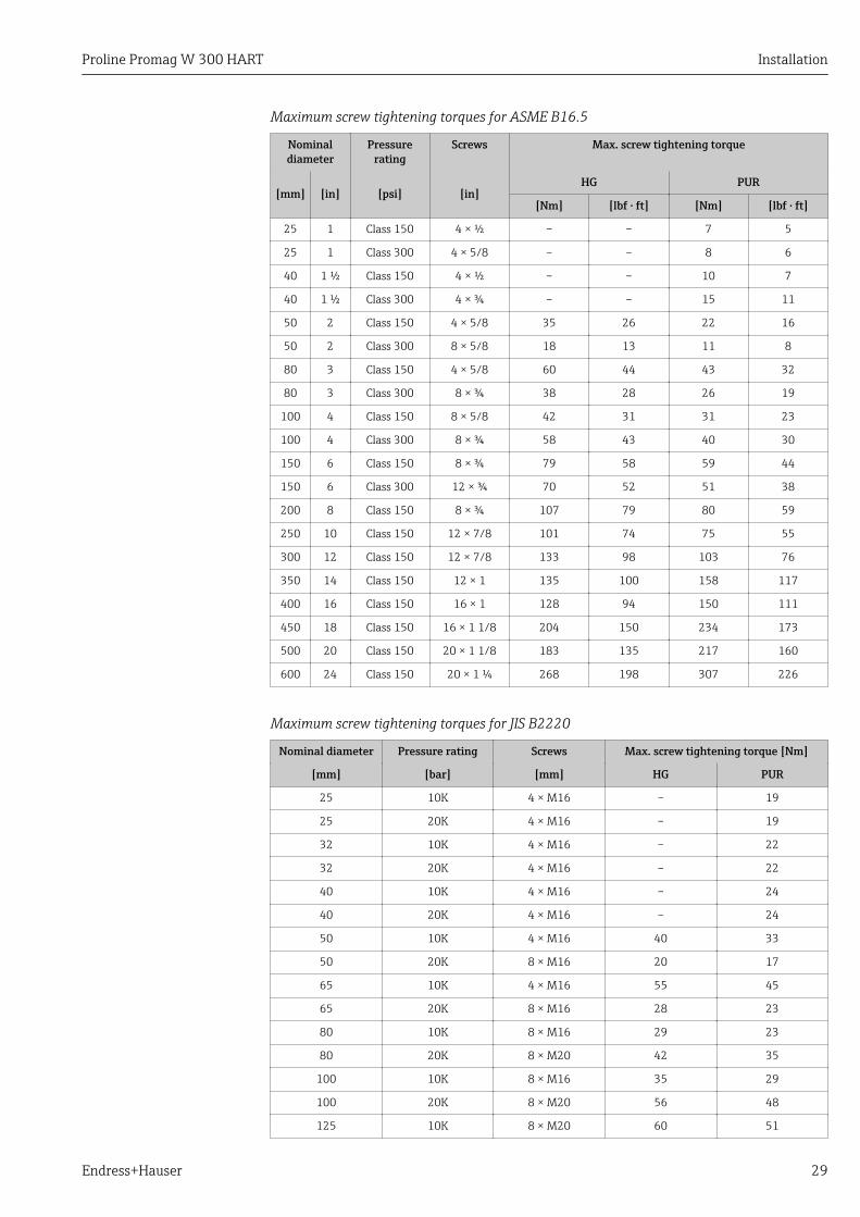
Maximum screw tightening torques for ASME B16.5
Nominaldiameter
Pressurerating
Screws Max. screw tightening torque
[mm] [in] [psi] [in]HG PUR
[Nm] [lbf · ft] [Nm] [lbf · ft]
25 1 Class 150 4 × ½ – – 7 5
25 1 Class 300 4 × 5/8 – – 8 6
40 1 ½ Class 150 4 × ½ – – 10 7
40 1 ½ Class 300 4 × ¾ – – 15 11
50 2 Class 150 4 × 5/8 35 26 22 16
50 2 Class 300 8 × 5/8 18 13 11 8
80 3 Class 150 4 × 5/8 60 44 43 32
80 3 Class 300 8 × ¾ 38 28 26 19
100 4 Class 150 8 × 5/8 42 31 31 23
100 4 Class 300 8 × ¾ 58 43 40 30
150 6 Class 150 8 × ¾ 79 58 59 44
150 6 Class 300 12 × ¾ 70 52 51 38
200 8 Class 150 8 × ¾ 107 79 80 59
250 10 Class 150 12 × 7/8 101 74 75 55
300 12 Class 150 12 × 7/8 133 98 103 76
350 14 Class 150 12 × 1 135 100 158 117
400 16 Class 150 16 × 1 128 94 150 111
450 18 Class 150 16 × 1 1/8 204 150 234 173
500 20 Class 150 20 × 1 1/8 183 135 217 160
600 24 Class 150 20 × 1 ¼ 268 198 307 226
Maximum screw tightening torques for JIS B2220
Nominal diameter Pressure rating Screws Max. screw tightening torque [Nm]
[mm] [bar] [mm] HG PUR
25 10K 4 × M16 – 19
25 20K 4 × M16 – 19
32 10K 4 × M16 – 22
32 20K 4 × M16 – 22
40 10K 4 × M16 – 24
40 20K 4 × M16 – 24
50 10K 4 × M16 40 33
50 20K 8 × M16 20 17
65 10K 4 × M16 55 45
65 20K 8 × M16 28 23
80 10K 8 × M16 29 23
80 20K 8 × M20 42 35
100 10K 8 × M16 35 29
100 20K 8 × M20 56 48
125 10K 8 × M20 60 51

Installation Proline Promag W 300 HART
30 Endress+Hauser
Nominal diameter Pressure rating Screws Max. screw tightening torque [Nm]
[mm] [bar] [mm] HG PUR
125 20K 8 × M22 91 79
150 10K 8 × M20 75 63
150 20K 12 × M22 81 72
200 10K 12 × M20 61 52
200 20K 12 × M22 91 80
250 10K 12 × M22 100 87
250 20K 12 × M24 159 144
300 10K 16 × M22 74 63
300 20K 16 × M24 138 124
Nominal screw tightening torques for JIS B2220
Nominal diameter Pressure rating Screws Nom. screw tightening torque [Nm]
[mm] [bar] [mm] HG PUR
350 10K 16 × M22 109 109
20K 16 × M30×3 217 217
400 10K 16 × M24 163 163
20K 16 × M30×3 258 258
450 10K 16 × M24 155 155
20K 16 × M30×3 272 272
500 10K 16 × M24 183 183
20K 16 × M30×3 315 315
600 10K 16 × M30 235 235
20K 16 × M36×3 381 381
700 10K 16 × M30 300 300
750 10K 16 × M30 339 339
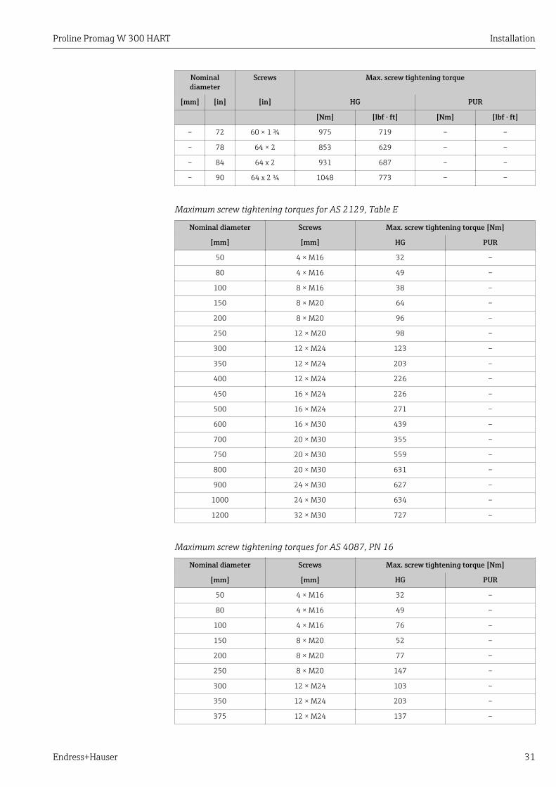
Maximum screw tightening torques for AWWA C207, Class D
Nominaldiameter
Screws Max. screw tightening torque
[mm] [in] [in] HG PUR
[Nm] [lbf · ft] [Nm] [lbf · ft]
700 28 28 × 1 ¼ 247 182 292 215
750 30 28 × 1 ¼ 287 212 302 223
800 32 28 × 1 ½ 394 291 422 311
900 36 32 × 1 ½ 419 309 430 317
1000 40 36 × 1 ½ 420 310 477 352
– 42 36 × 1 ½ 528 389 518 382
– 48 44 × 1 ½ 552 407 531 392
– 54 44 × 1 ¾ 730 538 – –
– 60 52 × 1 ¾ 758 559 – –
– 66 52 × 1 ¾ 946 698 – –
Proline Promag W 300 HART Installation
Endress+Hauser 31
Nominaldiameter
Screws Max. screw tightening torque
[mm] [in] [in] HG PUR
[Nm] [lbf · ft] [Nm] [lbf · ft]
– 72 60 × 1 ¾ 975 719 – –
– 78 64 × 2 853 629 – –
– 84 64 x 2 931 687 – –
– 90 64 x 2 ¼ 1048 773 – –
Maximum screw tightening torques for AS 2129, Table E
Nominal diameter Screws Max. screw tightening torque [Nm]
[mm] [mm] HG PUR
50 4 × M16 32 –
80 4 × M16 49 –
100 8 × M16 38 –
150 8 × M20 64 –
200 8 × M20 96 –
250 12 × M20 98 –
300 12 × M24 123 –
350 12 × M24 203 –
400 12 × M24 226 –
450 16 × M24 226 –
500 16 × M24 271 –
600 16 × M30 439 –
700 20 × M30 355 –
750 20 × M30 559 –
800 20 × M30 631 –
900 24 × M30 627 –
1000 24 × M30 634 –
1200 32 × M30 727 –
Maximum screw tightening torques for AS 4087, PN 16
Nominal diameter Screws Max. screw tightening torque [Nm]
[mm] [mm] HG PUR
50 4 × M16 32 –
80 4 × M16 49 –
100 4 × M16 76 –
150 8 × M20 52 –
200 8 × M20 77 –
250 8 × M20 147 –
300 12 × M24 103 –
350 12 × M24 203 –
375 12 × M24 137 –
Installation Proline Promag W 300 HART
32 Endress+Hauser
Nominal diameter Screws Max. screw tightening torque [Nm]
[mm] [mm] HG PUR
400 12 × M24 226 –
450 12 × M24 301 –
500 16 × M24 271 –
600 16 × M27 393 –
700 20 × M27 330 –
750 20 × M30 529 –
800 20 × M33 631 –
900 24 × M33 627 –
1000 24 × M33 595 –
1200 32 × M33 703 –
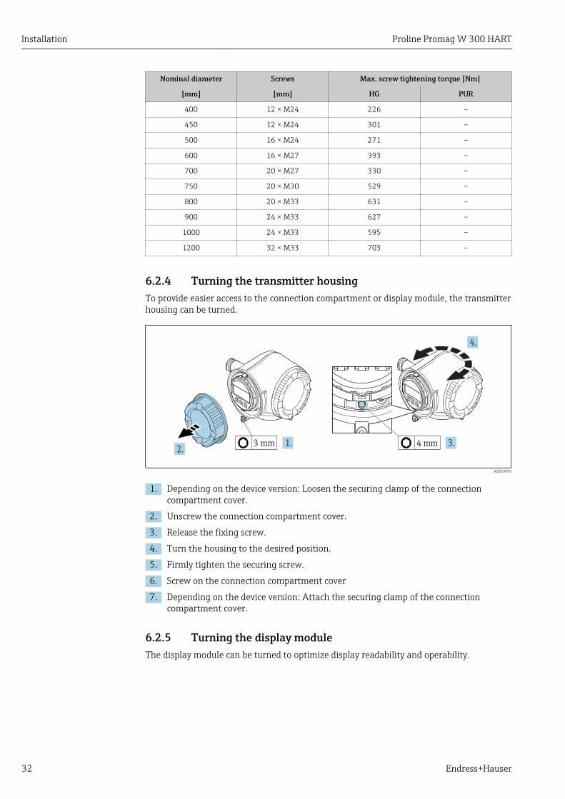
6.2.4 Turning the transmitter housingTo provide easier access to the connection compartment or display module, the transmitterhousing can be turned.
Nic
ht
unte
r
are
öffn
en
+
E
ESC
–
1.2.
Nic
ht
unte
r
are
öffn
en
+
E
ESC
–
3.3 mm 4 mm
4.
A0029993
1. Depending on the device version: Loosen the securing clamp of the connectioncompartment cover.
2. Unscrew the connection compartment cover.
3. Release the fixing screw.
4. Turn the housing to the desired position.
5. Firmly tighten the securing screw.
6. Screw on the connection compartment cover
7. Depending on the device version: Attach the securing clamp of the connectioncompartment cover.
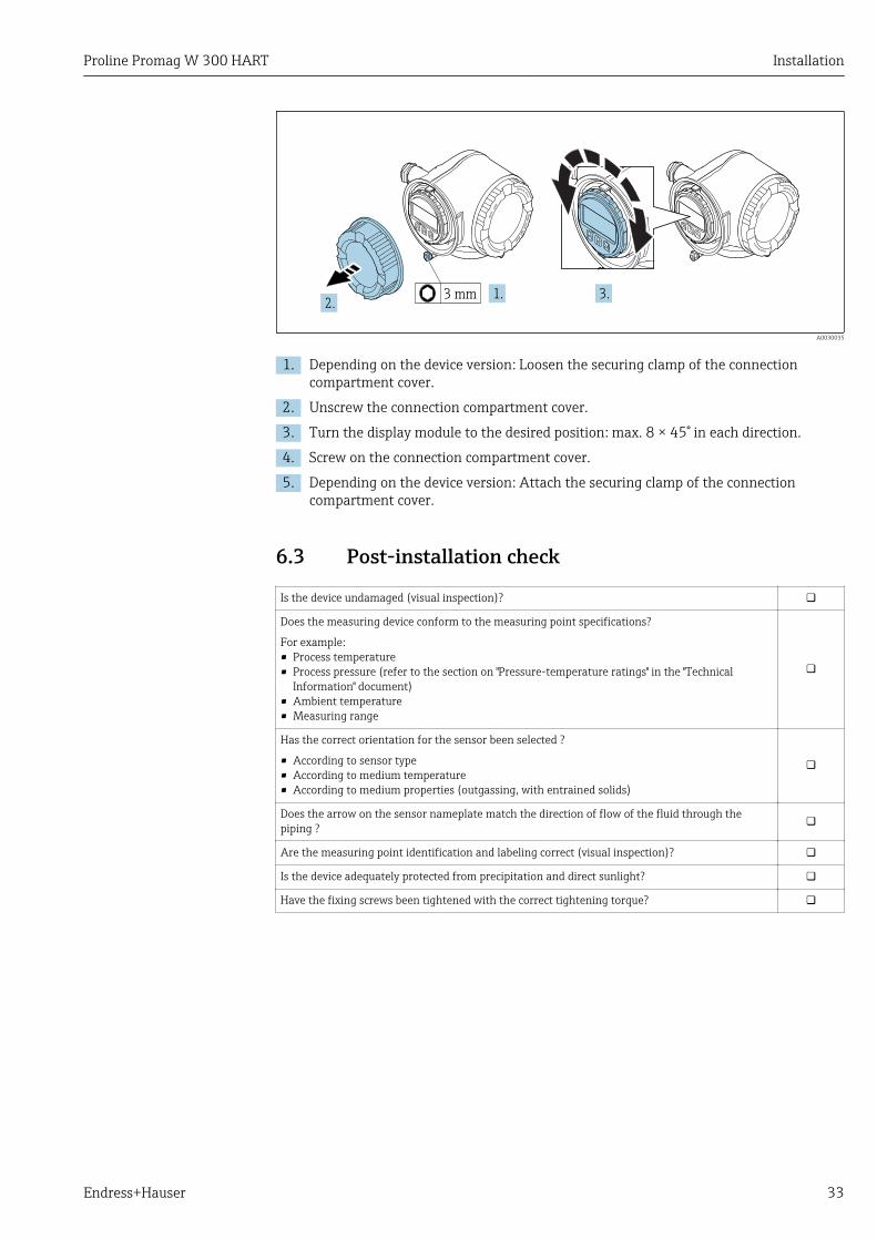
6.2.5 Turning the display moduleThe display module can be turned to optimize display readability and operability.
Proline Promag W 300 HART Installation
Endress+Hauser 33
Nic
ht
unte
r
are
öffn
en
+
E
ESC
–
1.2.
Nic
ht
unte
r
are
öffn
en
+
E
ESC
–
3.3 mm
+
E
ESC
–
A0030035
1. Depending on the device version: Loosen the securing clamp of the connectioncompartment cover.
2. Unscrew the connection compartment cover.
3. Turn the display module to the desired position: max. 8 × 45° in each direction.
4. Screw on the connection compartment cover.
5. Depending on the device version: Attach the securing clamp of the connectioncompartment cover.
6.3 Post-installation check
Is the device undamaged (visual inspection)?
Does the measuring device conform to the measuring point specifications?
For example:• Process temperature• Process pressure (refer to the section on "Pressure-temperature ratings" in the "Technical
Information" document)• Ambient temperature• Measuring range
Has the correct orientation for the sensor been selected ?
• According to sensor type• According to medium temperature• According to medium properties (outgassing, with entrained solids)
Does the arrow on the sensor nameplate match the direction of flow of the fluid through thepiping ?
Are the measuring point identification and labeling correct (visual inspection)?
Is the device adequately protected from precipitation and direct sunlight?
Have the fixing screws been tightened with the correct tightening torque?
Electrical connection Proline Promag W 300 HART
34 Endress+Hauser
7 Electrical connectionNOTICE
The measuring device does not have an internal circuit breaker.‣ For this reason, assign the measuring device a switch or power-circuit breaker so that
the power supply line can be easily disconnected from the mains.‣ Although the measuring device is equipped with a fuse, additional overcurrent
protection (maximum 10 A) should be integrated into the system installation.
7.1 Connection conditions
7.1.1 Required tools• For cable entries: Use corresponding tools• For securing clamp: Allen key 3 mm• Wire stripper• When using stranded cables: Crimper for wire end ferrule• For removing cables from terminal: Flat blade screwdriver ≤ 3 mm (0.12 in)
7.1.2 Requirements for connecting cableThe connecting cables provided by the customer must fulfill the following requirements.
Electrical safetyIn accordance with applicable federal/national regulations.
Protective ground cableCable ≥2.08 mm2 (14 AWG)
The grounding impedance must be less than 1 Ω.
Permitted temperature range• The installation guidelines that apply in the country of installation must be observed.• The cables must be suitable for the minimum and maximum temperatures to be
expected.
Power supply cableStandard installation cable is sufficient.
Signal cableCurrent output 4 to 20 mA HART
A shielded cable is recommended. Observe grounding concept of the plant.
Current output 0/4 to 20 mA
Standard installation cable is sufficient.
Pulse/frequency/switch output
Standard installation cable is sufficient.
Double pulse output
Standard installation cable is sufficient.

Proline Promag W 300 HART Electrical connection
Endress+Hauser 35
Relay output
Standard installation cable is sufficient.
Current input 0/4 to 20 mA
Standard installation cable is sufficient.
Status input
Standard installation cable is sufficient.
Cable diameter• Cable glands supplied:
M20 × 1.5 with cable 6 to 12 mm (0.24 to 0.47 in)• Spring-loaded terminals: Suitable for strands and strands with ferrules.
Conductor cross-section 0.2 to 2.5 mm2 (24 to 12 AWG).
Requirements for the connecting cable - Remote display and operating moduleDKX001
Optionally available connecting cable
A cable is supplied depending on the order option• Order code for measuring device: order code 030 for "Display; operation", option O
or• Order code for measuring device: order code 030 for "Display; operation", option M
and• Order code for DKX001: order code 040 for "Cable", option A, B, D, E
Standard cable 2 × 2 × 0.34 mm2 (22 AWG) PVC cable with common shield (2 pairs, pair-stranded)
Flame resistance According to DIN EN 60332-1-2
Oil-resistance According to DIN EN 60811-2-1
Shielding Tin-plated copper-braid, optical cover ≥ 85 %
Capacitance: core/shield ≤200 pF/m
L/R ≤24 µH/Ω
Available cable length 5 m (15 ft)/10 m (35 ft)/20 m (65 ft)/30 m (100 ft)
Operating temperature When mounted in a fixed position: –50 to +105 °C (–58 to +221 °F); when cablecan move freely: –25 to +105 °C (–13 to +221 °F)
Standard cable - customer-specific cable
No cable is supplied, and it must be provided by the customer (up to max.300 m (1 000 ft)) for the following order option:Order code for DKX001: Order code 040 for "Cable", option 1 "None, provided by customer,max 300 m"
A standard cable can be used as the connecting cable.
Standard cable 4 cores (2 pairs); pair-stranded with common shield
Shielding Tin-plated copper-braid, optical cover ≥ 85 %
Capacitance: core/shield Maximum 1 000 nF for Zone 1, Class I, Division 1
L/R Maximum 24 µH/Ω for Zone 1, Class I, Division 1
Cable length Maximum 300 m (1 000 ft), see the following table

Electrical connection Proline Promag W 300 HART
36 Endress+Hauser
Cross-section
Max. cable length for use inNon-hazardous area,Ex Zone 2, Class I, Division 2Ex Zone 1, Class I, Division 1
0.34 mm2 (22 AWG) 80 m (270 ft)
0.50 mm2 (20 AWG) 120 m (400 ft)
0.75 mm2 (18 AWG) 180 m (600 ft)
1.00 mm2 (17 AWG) 240 m (800 ft)
1.50 mm2 (15 AWG) 300 m (1 000 ft)
Proline Promag W 300 HART Electrical connection
Endress+Hauser 37
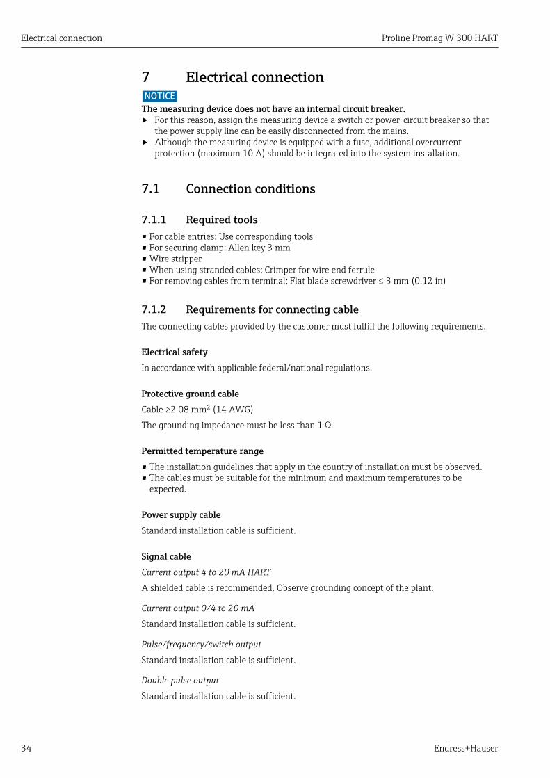
7.1.3 Terminal assignment
Transmitter: supply voltage, input/outputsThe terminal assignment of the inputs and outputs depends on the individual orderversion of the device. The device-specific terminal assignment is documented on anadhesive label in the terminal cover.
Supply voltage Input/output 1 Input/output 2 Input/output 3
1 (+) 2 (–) 26 (+) 27 (–) 24 (+) 25 (–) 22 (+) 23 (–)
Device-specific terminal assignment: adhesive label in terminal cover.
Terminal assignment of the remote display and operating module → 40.
7.1.4 Preparing the measuring deviceNOTICE
Insufficient sealing of the housing!Operational reliability of the measuring device could be compromised.‣ Use suitable cable glands corresponding to the degree of protection.
1. Remove dummy plug if present.
2. If the measuring device is supplied without cable glands:Provide suitable cable gland for corresponding connecting cable.
3. If the measuring device is supplied with cable glands:Observe requirements for connecting cables → 34.
7.2 Connecting the measuring deviceNOTICE
Limitation of electrical safety due to incorrect connection!‣ Have electrical connection work carried out by appropriately trained specialists only.‣ Observe applicable federal/national installation codes and regulations.‣ Comply with local workplace safety regulations.‣ Always connect the protective ground cable before connecting additional cables.‣ For use in potentially explosive atmospheres, observe the information in the device-
specific Ex documentation.
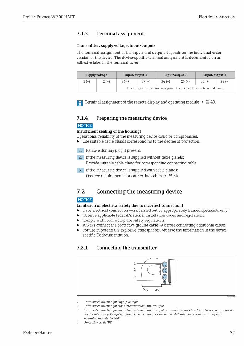
7.2.1 Connecting the transmitter
1
2
3
4
A0026781
1 Terminal connection for supply voltage2 Terminal connection for signal transmission, input/output3 Terminal connection for signal transmission, input/output or terminal connection for network connection via
service interface (CDI-RJ45); optional: connection for external WLAN antenna or remote display andoperating module DKX001
4 Protective earth (PE)
Electrical connection Proline Promag W 300 HART
38 Endress+Hauser
Nic
ht
unte
r
ar
e
öffn
en
+
E
ESC
–
1.2.
Nic
ht
unte
r
ar
e
öffn
en
+
E
ESC
–
+
E
ESC
–
3.
3.
4.
3 mm
A0029813
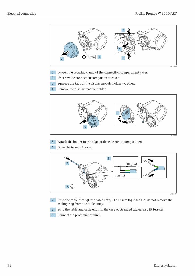
1. Loosen the securing clamp of the connection compartment cover.
2. Unscrew the connection compartment cover.
3. Squeeze the tabs of the display module holder together.
4. Remove the display module holder.
Nic
ht
unte
r
ar
e
öffnen
Nicht unter
Spannung öffnen
Do not open when
energizedNe pas ouvrir
sous tension
Power
I/O
+
E
ESC
–
5.
Nic
ht
unte
r
ar
e
öffnen
Nicht unter
Spannung öffnen
Do not open when
energizedNe pas ouvrir
sous tension
Power
I/O
+
E
ESC
–
Power
Nicht unter
Spannung öffnen
Do not open w
hen
energized
Ne pas ouvrir
sous tension
I/O
6.
A0029814
5. Attach the holder to the edge of the electronics compartment.
6. Open the terminal cover.
Nic
ht
unte
r
ar
e
öffn
en
+
E
ESC
–
10 (0.4)
mm (in)
7.
8.
9.
A0029815
7. Push the cable through the cable entry . To ensure tight sealing, do not remove thesealing ring from the cable entry.
8. Strip the cable and cable ends. In the case of stranded cables, also fit ferrules.
9. Connect the protective ground.

Proline Promag W 300 HART Electrical connection
Endress+Hauser 39
Nic
ht
unte
r
ar
e
öffn
en
+
E
ESC
–
10.
11.
22 mm
24 mm
A0029816
10. Connect the cable in accordance with the terminal assignment . Signal cable terminal assignment: The device-specific terminal assignment is
documented on an adhesive label in the terminal cover.Supply voltage terminal assignment: Adhesive label in the terminal cover or→ 37.
11. Firmly tighten the cable glands. This concludes the cable connection process.
12. Close the terminal cover.
13. Fit the display module holder in the electronics compartment.
14. Screw on the connection compartment cover.
15. Secure the securing clamp of the connection compartment cover.
Removing a cable
3 (0.12)
2.
1.
A0029598
6 Engineering unit mm (in)
1. To remove a cable from the terminal, use a flat-blade screwdriver to push the slotbetween the two terminal holes
2. while simultaneously pulling the cable end out of the terminal.
Electrical connection Proline Promag W 300 HART
40 Endress+Hauser
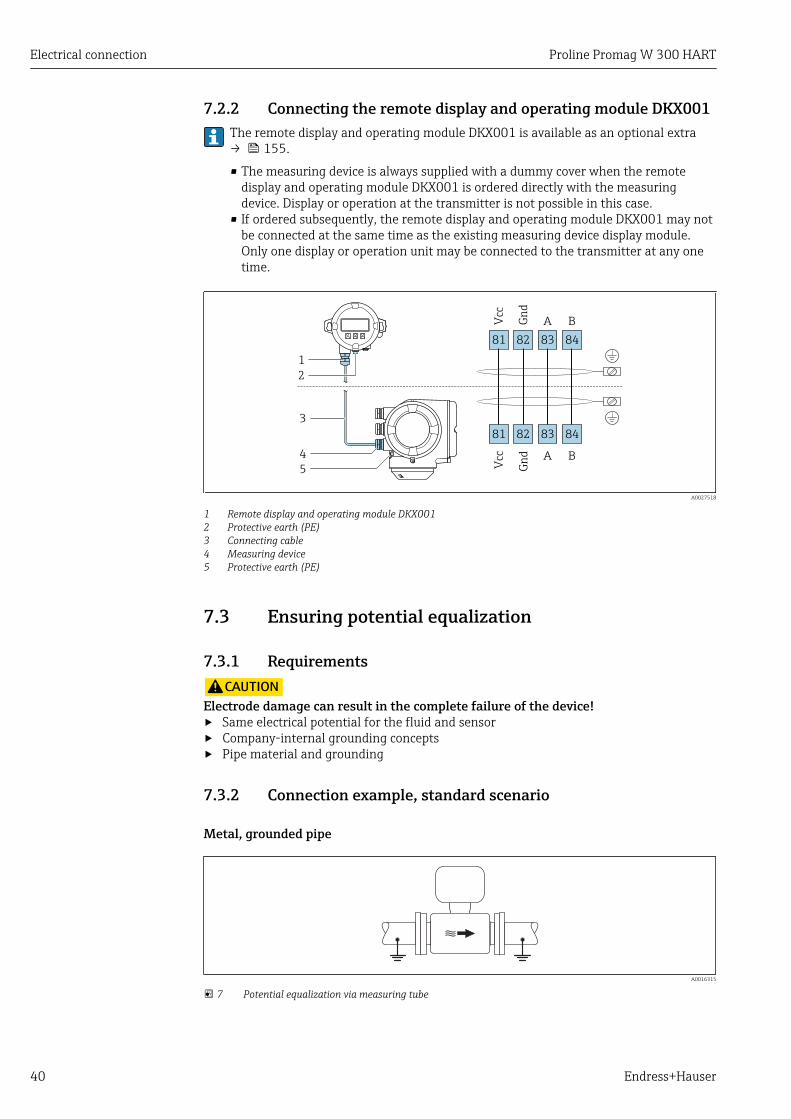
7.2.2 Connecting the remote display and operating module DKX001The remote display and operating module DKX001 is available as an optional extra→ 155.
• The measuring device is always supplied with a dummy cover when the remotedisplay and operating module DKX001 is ordered directly with the measuringdevice. Display or operation at the transmitter is not possible in this case.
• If ordered subsequently, the remote display and operating module DKX001 may notbe connected at the same time as the existing measuring device display module.Only one display or operation unit may be connected to the transmitter at any onetime.
1
3
81
Vcc
82
Gn
d
83
A
84
B
81
Vcc
82
Gn
d
83
A
84
B
2
4
5
A0027518
1 Remote display and operating module DKX0012 Protective earth (PE)3 Connecting cable4 Measuring device5 Protective earth (PE)
7.3 Ensuring potential equalization
7.3.1 RequirementsLCAUTION
Electrode damage can result in the complete failure of the device!‣ Same electrical potential for the fluid and sensor‣ Company-internal grounding concepts‣ Pipe material and grounding
7.3.2 Connection example, standard scenario
Metal, grounded pipe
A0016315
7 Potential equalization via measuring tube
Proline Promag W 300 HART Electrical connection
Endress+Hauser 41
7.3.3 Connection example in special situations
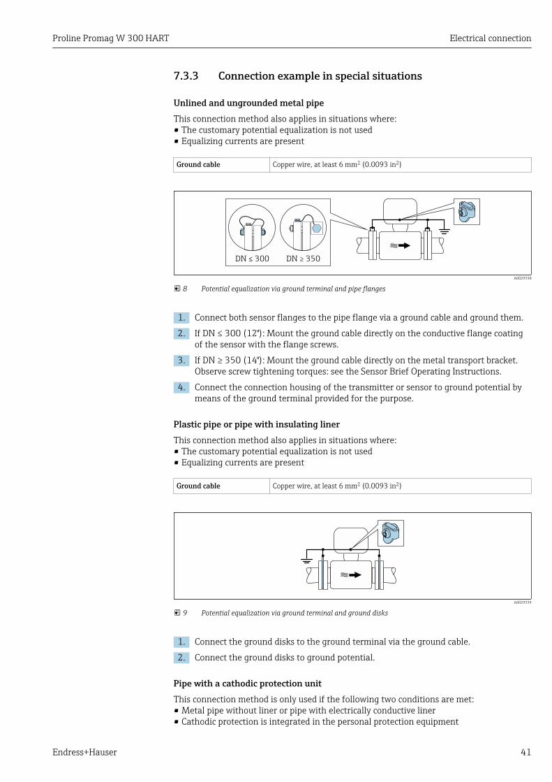
Unlined and ungrounded metal pipeThis connection method also applies in situations where:• The customary potential equalization is not used• Equalizing currents are present
Ground cable Copper wire, at least 6 mm2 (0.0093 in2)
DN 300≤ DN 350≥
A0029338
8 Potential equalization via ground terminal and pipe flanges
1. Connect both sensor flanges to the pipe flange via a ground cable and ground them.
2. If DN ≤ 300 (12"): Mount the ground cable directly on the conductive flange coatingof the sensor with the flange screws.
3. If DN ≥ 350 (14"): Mount the ground cable directly on the metal transport bracket.Observe screw tightening torques: see the Sensor Brief Operating Instructions.
4. Connect the connection housing of the transmitter or sensor to ground potential bymeans of the ground terminal provided for the purpose.
Plastic pipe or pipe with insulating linerThis connection method also applies in situations where:• The customary potential equalization is not used• Equalizing currents are present
Ground cable Copper wire, at least 6 mm2 (0.0093 in2)
A0029339
9 Potential equalization via ground terminal and ground disks
1. Connect the ground disks to the ground terminal via the ground cable.
2. Connect the ground disks to ground potential.
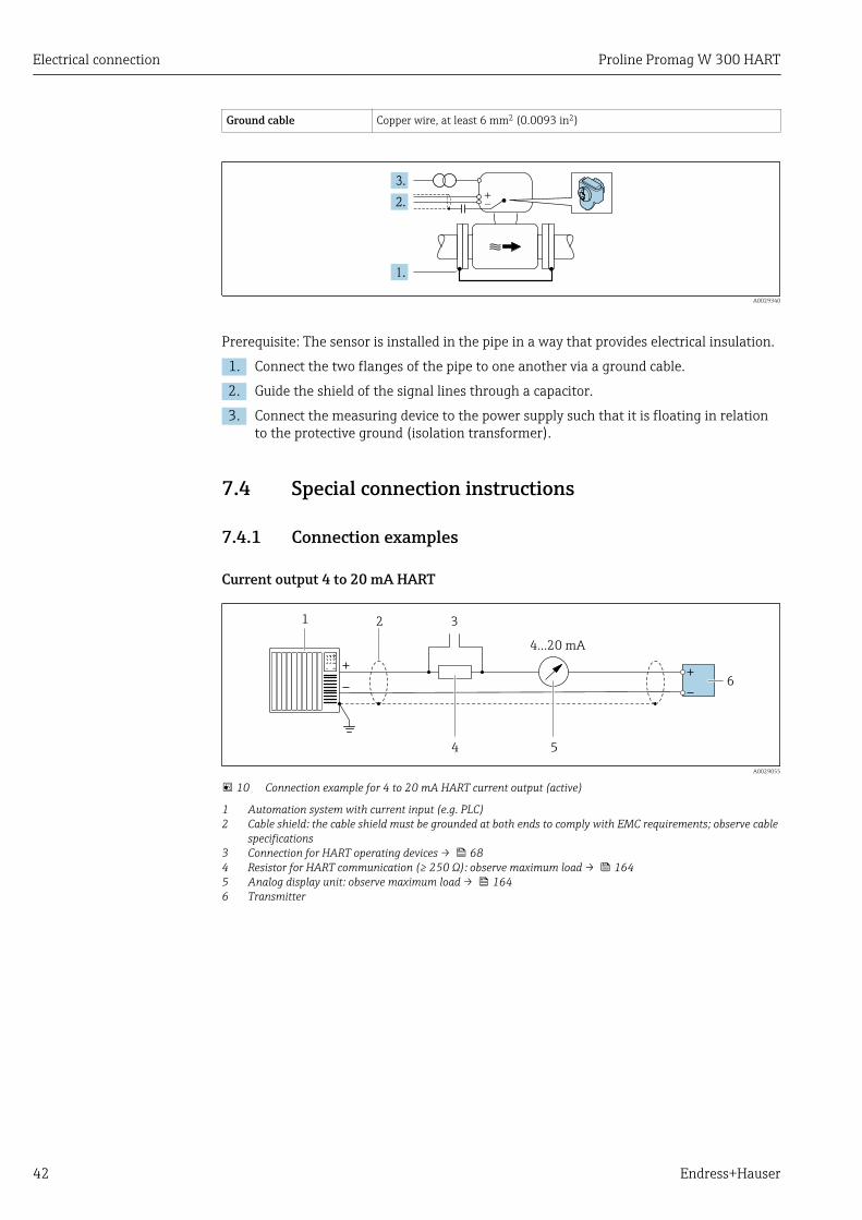
Pipe with a cathodic protection unitThis connection method is only used if the following two conditions are met:• Metal pipe without liner or pipe with electrically conductive liner• Cathodic protection is integrated in the personal protection equipment
Electrical connection Proline Promag W 300 HART
42 Endress+Hauser
Ground cable Copper wire, at least 6 mm2 (0.0093 in2)
+
–
A0029340
Prerequisite: The sensor is installed in the pipe in a way that provides electrical insulation.
1. Connect the two flanges of the pipe to one another via a ground cable.
2. Guide the shield of the signal lines through a capacitor.
3. Connect the measuring device to the power supply such that it is floating in relationto the protective ground (isolation transformer).
7.4 Special connection instructions
7.4.1 Connection examples
Current output 4 to 20 mA HART
4
4...20 mA
5
21 3
6
A0029055
10 Connection example for 4 to 20 mA HART current output (active)
1 Automation system with current input (e.g. PLC)2 Cable shield: the cable shield must be grounded at both ends to comply with EMC requirements; observe cable
specifications3 Connection for HART operating devices → 684 Resistor for HART communication (≥ 250 Ω): observe maximum load → 1645 Analog display unit: observe maximum load → 1646 Transmitter
Proline Promag W 300 HART Electrical connection
Endress+Hauser 43
2 3
4...20 mA
41
5
A0028762
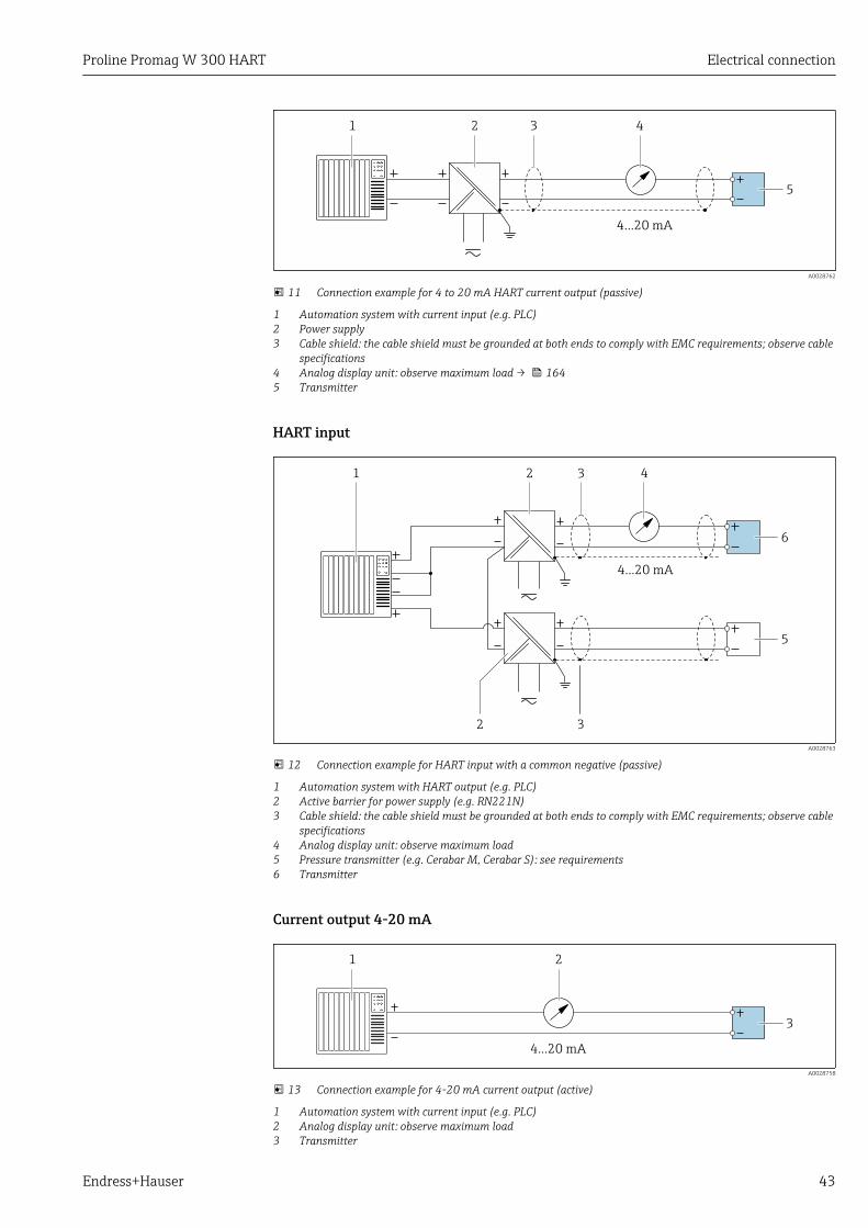
11 Connection example for 4 to 20 mA HART current output (passive)
1 Automation system with current input (e.g. PLC)2 Power supply3 Cable shield: the cable shield must be grounded at both ends to comply with EMC requirements; observe cable
specifications4 Analog display unit: observe maximum load → 1645 Transmitter
HART input
2
4...20 mA
41
2
3
3
6
5
A0028763
12 Connection example for HART input with a common negative (passive)
1 Automation system with HART output (e.g. PLC)2 Active barrier for power supply (e.g. RN221N)3 Cable shield: the cable shield must be grounded at both ends to comply with EMC requirements; observe cable
specifications4 Analog display unit: observe maximum load5 Pressure transmitter (e.g. Cerabar M, Cerabar S): see requirements6 Transmitter
Current output 4-20 mA
4...20 mA
21
3
A0028758
13 Connection example for 4-20 mA current output (active)
1 Automation system with current input (e.g. PLC)2 Analog display unit: observe maximum load3 Transmitter

Electrical connection Proline Promag W 300 HART
44 Endress+Hauser
2
4...20 mA
31
4
A0028759
14 Connection example for 4-20 mA current output (passive)
1 Automation system with current input (e.g. PLC)2 Active barrier for power supply (e.g. RN221N)3 Analog display unit: observe maximum load4 Transmitter
Pulse/frequency output
1 2
3
12345
A0028761
15 Connection example for pulse/frequency output (passive)
1 Automation system with pulse/frequency input (e.g. PLC)2 Power supply3 Transmitter: Observe input values → 164
Switch output
1 2
3
A0028760
16 Connection example for switch output (passive)
1 Automation system with switch input (e.g. PLC)2 Power supply3 Transmitter: Observe input values → 164

Proline Promag W 300 HART Electrical connection
Endress+Hauser 45
Double pulse output
1
2
3
4
A0029280
17 Connection example for double pulse output (active)
1 Automation system with double pulse input (e.g. PLC)2 Transmitter: Observe input values → 1663 Double pulse output4 Double pulse output (slave), phase-shifted
1
3
2
4
5
A0029279
18 Connection example for double pulse output (passive)
1 Automation system with double pulse input (e.g. PLC)2 Power supply3 Transmitter: Observe input values → 1664 Double pulse output5 Double pulse output (slave), phase-shifted
Relay output
1 2
3
A0028760
19 Connection example for relay output (passive)
1 Automation system with relay input (e.g. PLC)2 Power supply3 Transmitter: Observe input values → 166

Electrical connection Proline Promag W 300 HART
46 Endress+Hauser
Current input
31
4
2
A0028915
20 Connection example for 4 to 20 mA current input
1 Power supply2 Terminal box3 External measuring device (for reading in pressure or temperature, for instance)4 Transmitter
Status input
1 2
3
A0028764
21 Connection example for status input
1 Automation system with status output (e.g. PLC)2 Power supply3 Transmitter
7.5 Ensuring the degree of protectionThe measuring device fulfills all the requirements for the IP66/67 degree of protection,Type 4X enclosure.
To guarantee IP66/67 degree of protection, Type 4X enclosure, carry out the followingsteps after the electrical connection:
1. Check that the housing seals are clean and fitted correctly.
2. Dry, clean or replace the seals if necessary.
3. Tighten all housing screws and screw covers.
4. Firmly tighten the cable glands.
Proline Promag W 300 HART Electrical connection
Endress+Hauser 47
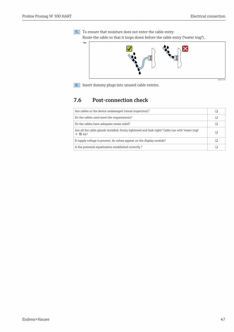
5. To ensure that moisture does not enter the cable entry:Route the cable so that it loops down before the cable entry ("water trap").
A0029278
6. Insert dummy plugs into unused cable entries.
7.6 Post-connection check
Are cables or the device undamaged (visual inspection)?
Do the cables used meet the requirements?
Do the cables have adequate strain relief?
Are all the cable glands installed, firmly tightened and leak-tight? Cable run with "water trap"→ 46?
If supply voltage is present, do values appear on the display module?
Is the potential equalization established correctly ?
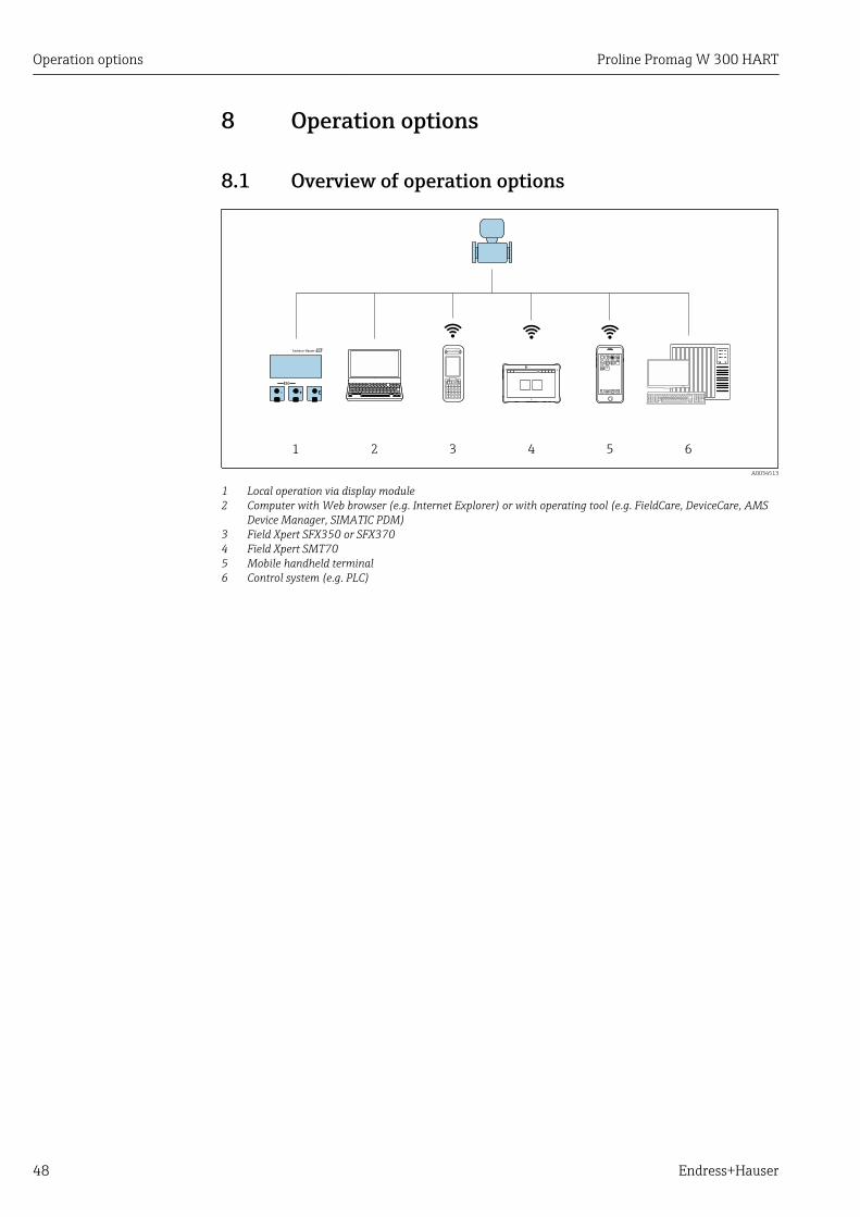
Operation options Proline Promag W 300 HART
48 Endress+Hauser
8 Operation options
8.1 Overview of operation options
1 62
E+-
ESC
53 4
A0034513
1 Local operation via display module2 Computer with Web browser (e.g. Internet Explorer) or with operating tool (e.g. FieldCare, DeviceCare, AMS
Device Manager, SIMATIC PDM)3 Field Xpert SFX350 or SFX3704 Field Xpert SMT705 Mobile handheld terminal6 Control system (e.g. PLC)
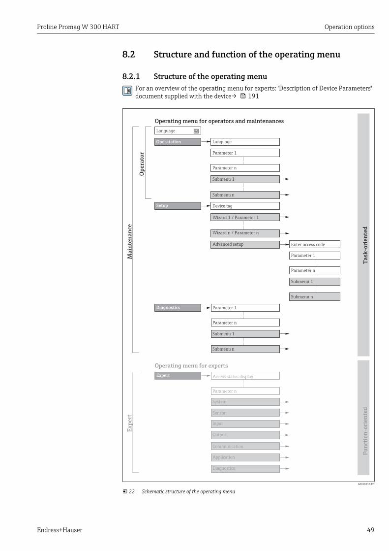
Proline Promag W 300 HART Operation options
Endress+Hauser 49
8.2 Structure and function of the operating menu
8.2.1 Structure of the operating menuFor an overview of the operating menu for experts: "Description of Device Parameters"document supplied with the device→ 191
!
Expert
System
Sensor
Communication
Application
Diagnostics
Access status display
Output
Operating menu for experts
Language
Operatation Language
Parameter 1
Setup
Submenu 1
Submenu n
Device tag
Advanced setup Enter access code
Parameter 1
Parameter n
Submenu 1
Submenu n
Diagnostics Parameter 1
Parameter n
Submenu 1
Submenu n
Operating menu for operators and maintenances
Parameter n
Op
era
tor
Ma
inte
na
nce
Ta
sk-o
rie
nte
dF
un
ctio
n-o
rie
nte
d
Ex
pe
rt
Wizard 1 / Parameter 1
Wizard n / Parameter n
Parameter n
Input
A0018237-EN
22 Schematic structure of the operating menu
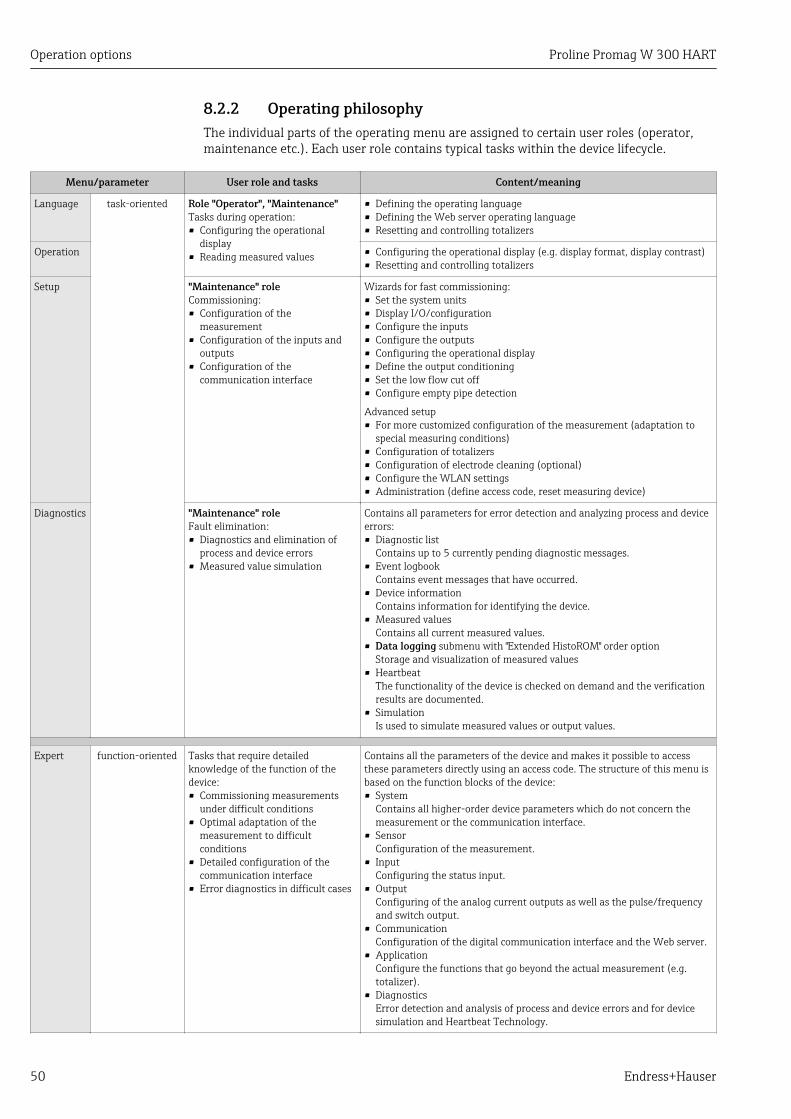
Operation options Proline Promag W 300 HART
50 Endress+Hauser
8.2.2 Operating philosophyThe individual parts of the operating menu are assigned to certain user roles (operator,maintenance etc.). Each user role contains typical tasks within the device lifecycle.
Menu/parameter User role and tasks Content/meaning
Language task-oriented Role "Operator", "Maintenance"Tasks during operation:• Configuring the operational
display• Reading measured values
• Defining the operating language• Defining the Web server operating language• Resetting and controlling totalizers
Operation • Configuring the operational display (e.g. display format, display contrast)• Resetting and controlling totalizers
Setup "Maintenance" roleCommissioning:• Configuration of the
measurement• Configuration of the inputs and
outputs• Configuration of the
communication interface
Wizards for fast commissioning:• Set the system units• Display I/O/configuration• Configure the inputs• Configure the outputs• Configuring the operational display• Define the output conditioning• Set the low flow cut off• Configure empty pipe detection
Advanced setup• For more customized configuration of the measurement (adaptation to
special measuring conditions)• Configuration of totalizers• Configuration of electrode cleaning (optional)• Configure the WLAN settings• Administration (define access code, reset measuring device)
Diagnostics "Maintenance" roleFault elimination:• Diagnostics and elimination of
process and device errors• Measured value simulation
Contains all parameters for error detection and analyzing process and deviceerrors:• Diagnostic list
Contains up to 5 currently pending diagnostic messages.• Event logbook
Contains event messages that have occurred.• Device information
Contains information for identifying the device.• Measured values
Contains all current measured values.• Data logging submenu with "Extended HistoROM" order option
Storage and visualization of measured values• Heartbeat
The functionality of the device is checked on demand and the verificationresults are documented.
• SimulationIs used to simulate measured values or output values.
Expert function-oriented Tasks that require detailedknowledge of the function of thedevice:• Commissioning measurements
under difficult conditions• Optimal adaptation of the
measurement to difficultconditions
• Detailed configuration of thecommunication interface
• Error diagnostics in difficult cases
Contains all the parameters of the device and makes it possible to accessthese parameters directly using an access code. The structure of this menu isbased on the function blocks of the device:• System
Contains all higher-order device parameters which do not concern themeasurement or the communication interface.
• SensorConfiguration of the measurement.
• InputConfiguring the status input.
• OutputConfiguring of the analog current outputs as well as the pulse/frequencyand switch output.
• CommunicationConfiguration of the digital communication interface and the Web server.
• ApplicationConfigure the functions that go beyond the actual measurement (e.g.totalizer).
• DiagnosticsError detection and analysis of process and device errors and for devicesimulation and Heartbeat Technology.
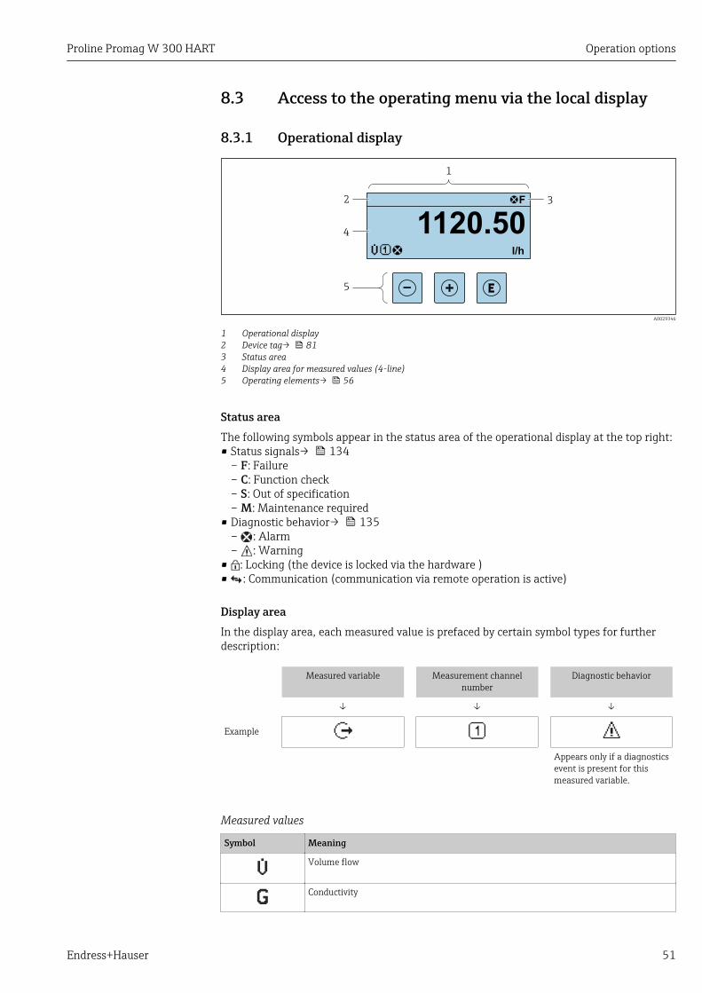
Proline Promag W 300 HART Operation options
Endress+Hauser 51
8.3 Access to the operating menu via the local display
8.3.1 Operational display
X X X X X X XX X
4
2
1
3
5
l/h
1120.50
F
A0029346
1 Operational display2 Device tag→ 813 Status area4 Display area for measured values (4-line)5 Operating elements→ 56
Status areaThe following symbols appear in the status area of the operational display at the top right:• Status signals→ 134
– F: Failure– C: Function check– S: Out of specification– M: Maintenance required
• Diagnostic behavior→ 135– : Alarm– : Warning
• : Locking (the device is locked via the hardware )• : Communication (communication via remote operation is active)
Display areaIn the display area, each measured value is prefaced by certain symbol types for furtherdescription:
Measured variable Measurement channelnumber
Diagnostic behavior
↓ ↓ ↓
Example
Appears only if a diagnosticsevent is present for thismeasured variable.
Measured values
Symbol Meaning
Volume flow
Conductivity
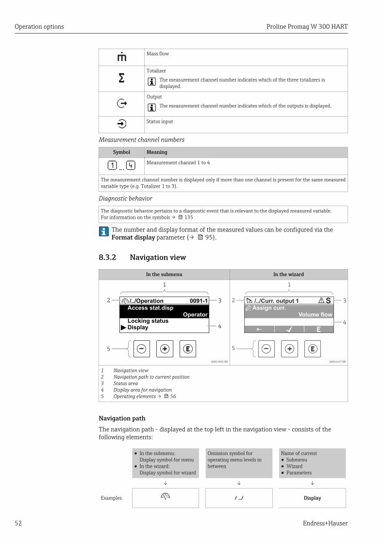
Operation options Proline Promag W 300 HART
52 Endress+Hauser
Mass flow
Totalizer
The measurement channel number indicates which of the three totalizers isdisplayed.
Output
The measurement channel number indicates which of the outputs is displayed.
Status input
Measurement channel numbers
Symbol Meaning
Measurement channel 1 to 4
The measurement channel number is displayed only if more than one channel is present for the same measuredvariable type (e.g. Totalizer 1 to 3).
Diagnostic behavior
The diagnostic behavior pertains to a diagnostic event that is relevant to the displayed measured variable.For information on the symbols → 135
The number and display format of the measured values can be configured via theFormat display parameter (→ 95).
8.3.2 Navigation view
In the submenu In the wizard
4
2
1
3
5
/../Operation 0091-1
Access stat.dispOperator
Locking statusDisplay
A0013993-EN
S
4
2
1
5
3/../Curr. output 1
Assign curr.Volume flow
A0016327-EN
12345
Navigation viewNavigation path to current positionStatus areaDisplay area for navigationOperating elements → 56
Navigation pathThe navigation path - displayed at the top left in the navigation view - consists of thefollowing elements:
• In the submenu:Display symbol for menu
• In the wizard:Display symbol for wizard
Omission symbol foroperating menu levels inbetween
Name of current• Submenu• Wizard• Parameters
↓ ↓ ↓
Examples / ../ Display
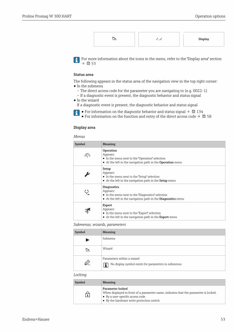
Proline Promag W 300 HART Operation options
Endress+Hauser 53
/ ../ Display
For more information about the icons in the menu, refer to the "Display area" section→ 53
Status areaThe following appears in the status area of the navigation view in the top right corner:• In the submenu
– The direct access code for the parameter you are navigating to (e.g. 0022-1)– If a diagnostic event is present, the diagnostic behavior and status signal
• In the wizardIf a diagnostic event is present, the diagnostic behavior and status signal
• For information on the diagnostic behavior and status signal → 134• For information on the function and entry of the direct access code → 58
Display area
Menus
Symbol Meaning
OperationAppears:• In the menu next to the "Operation" selection• At the left in the navigation path in the Operation menu
SetupAppears:• In the menu next to the "Setup" selection• At the left in the navigation path in the Setup menu
DiagnosticsAppears:• In the menu next to the "Diagnostics" selection• At the left in the navigation path in the Diagnostics menu
ExpertAppears:• In the menu next to the "Expert" selection• At the left in the navigation path in the Expert menu
Submenus, wizards, parameters
Symbol Meaning
Submenu
Wizard
Parameters within a wizard
No display symbol exists for parameters in submenus.
Locking
Symbol Meaning
Parameter lockedWhen displayed in front of a parameter name, indicates that the parameter is locked.• By a user-specific access code• By the hardware write protection switch
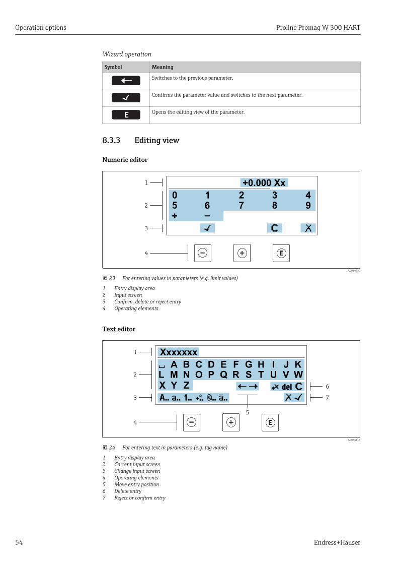
Operation options Proline Promag W 300 HART
54 Endress+Hauser
Wizard operation
Symbol Meaning
Switches to the previous parameter.
Confirms the parameter value and switches to the next parameter.
Opens the editing view of the parameter.
8.3.3 Editing view
Numeric editor
+0.000 Xx
0 1 2 3 4
+
5
1
2
3
4
6 7 8 9
–
A0034250
23 For entering values in parameters (e.g. limit values)
1 Entry display area2 Input screen3 Confirm, delete or reject entry4 Operating elements
Text editor
Xxxxxxx
A B C D E F G H I J K
M N O P Q R S T U V W
X Y
L
Z
1
2
3
5
6
7
4
A0034114
24 For entering text in parameters (e.g. tag name)
1 Entry display area2 Current input screen3 Change input screen4 Operating elements5 Move entry position6 Delete entry7 Reject or confirm entry
Proline Promag W 300 HART Operation options
Endress+Hauser 55
Using the operating elements in the editing view
Operating key(s) Meaning
Minus keyMove the entry position to the left.
Plus keyMove the entry position to the right.
Enter key• Press the key briefly: confirm your selection.• Press the key for 2 s: confirm the entry.
+Escape key combination (press keys simultaneously)Close the editing view without accepting the changes.
Input screens
Symbol Meaning
Upper case
Lower case
Numbers
Punctuation marks and special characters: = + – * / ² ³ ¼ ½ ¾ ( ) [ ] < >
Punctuation marks and special characters: ' " `^. , ; : ? ! % µ ° € $ £ ¥ § @ # / \ I ~ & _
Umlauts and accents
Controlling data entries
Symbol Meaning
Move entry position
Reject entry
Confirm entry
Delete character immediately to the left of the entry position
Delete character immediately to the right of the entry position
Clear all the characters entered
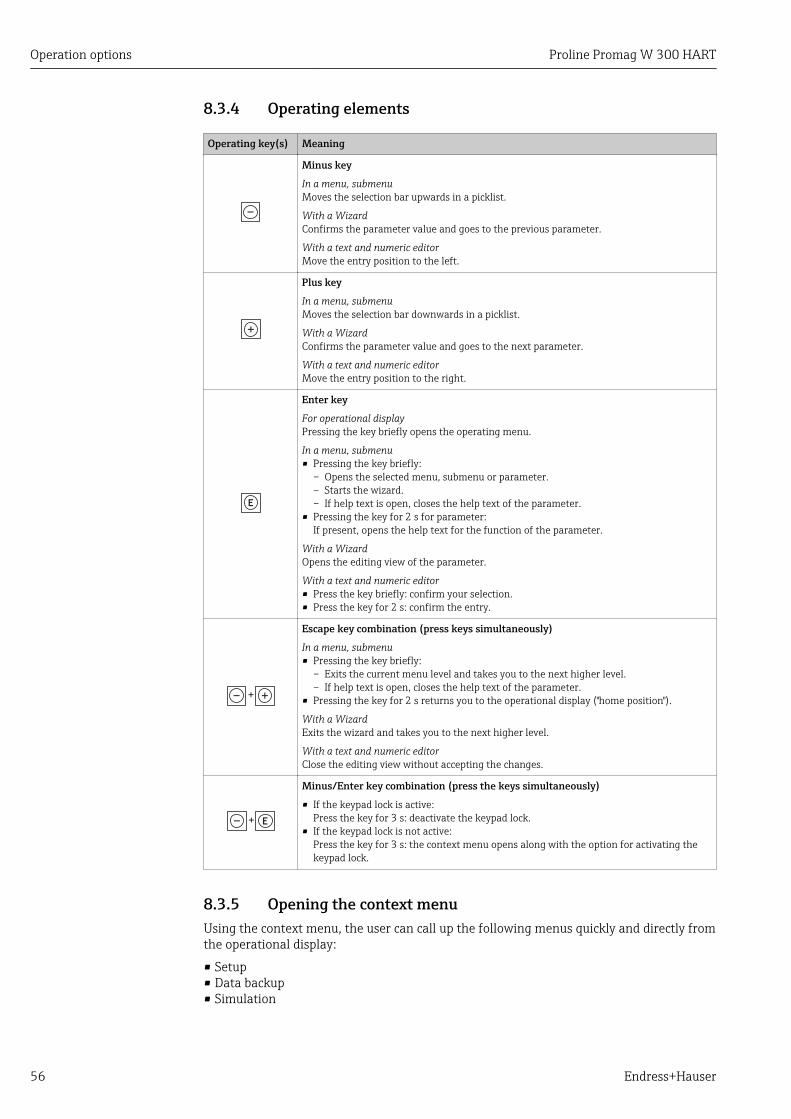
Operation options Proline Promag W 300 HART
56 Endress+Hauser
8.3.4 Operating elements
Operating key(s) Meaning
Minus key
In a menu, submenuMoves the selection bar upwards in a picklist.
With a WizardConfirms the parameter value and goes to the previous parameter.
With a text and numeric editorMove the entry position to the left.
Plus key
In a menu, submenuMoves the selection bar downwards in a picklist.
With a WizardConfirms the parameter value and goes to the next parameter.
With a text and numeric editorMove the entry position to the right.
Enter key
For operational displayPressing the key briefly opens the operating menu.
In a menu, submenu• Pressing the key briefly:
– Opens the selected menu, submenu or parameter.– Starts the wizard.– If help text is open, closes the help text of the parameter.
• Pressing the key for 2 s for parameter:If present, opens the help text for the function of the parameter.
With a WizardOpens the editing view of the parameter.
With a text and numeric editor• Press the key briefly: confirm your selection.• Press the key for 2 s: confirm the entry.
+
Escape key combination (press keys simultaneously)
In a menu, submenu• Pressing the key briefly:
– Exits the current menu level and takes you to the next higher level.– If help text is open, closes the help text of the parameter.
• Pressing the key for 2 s returns you to the operational display ("home position").
With a WizardExits the wizard and takes you to the next higher level.
With a text and numeric editorClose the editing view without accepting the changes.
+
Minus/Enter key combination (press the keys simultaneously)
• If the keypad lock is active:Press the key for 3 s: deactivate the keypad lock.
• If the keypad lock is not active:Press the key for 3 s: the context menu opens along with the option for activating thekeypad lock.
8.3.5 Opening the context menuUsing the context menu, the user can call up the following menus quickly and directly fromthe operational display:
• Setup• Data backup• Simulation

Proline Promag W 300 HART Operation options
Endress+Hauser 57
Calling up and closing the context menuThe user is in the operational display.
1. Press the and keys for longer than 3 seconds. The context menu opens.
XXXXXXXXXX
l/h
Setup
Conf.backupSimulationKeylock on
A0034608-EN
2. Press + simultaneously. The context menu is closed and the operational display appears.
Calling up the menu via the context menu1. Open the context menu.
2. Press to navigate to the desired menu.
3. Press to confirm the selection. The selected menu opens.

Operation options Proline Promag W 300 HART
58 Endress+Hauser
8.3.6 Navigating and selecting from listDifferent operating elements are used to navigate through the operating menu. Thenavigation path is displayed on the left in the header. Icons are displayed in front of theindividual menus. These icons are also shown in the header during navigation.
For an explanation of the navigation view with symbols and operating elements→ 52
Example: Setting the number of displayed measured values to "2 values"
X X X X X X XX X
20.500104-1
2 s
0091-1
0098-1
0098-1
0098-1
X X X X X X XX X10.50
2800
Hz
mA
3.
4.
5.
6.
7.
8.
1.
2. Display/operat.
Display/operat.
Setup
Main menu
English
Main menu
Format display
/ ../Display
Contrast displayDisplay intervall
1 value, max.
Setup
Access stat.disp
/ ../Display/operat.
Display
Locking status
1 value, max.
/ ../Format display
2 valuesVal. large+2val.
Bargr. + 1 value
Locking status
/ ../Display/operat.
Display
1 value, max.
/ ../Format display
2 values
Val. large+2val.
Bargr. + 1 value
Operator
Language
Language
A0029562-EN
8.3.7 Calling the parameter directlyA parameter number is assigned to every parameter to be able to access a parameterdirectly via the onsite display. Entering this access code in the Direct access parametercalls up the desired parameter directly.
Navigation pathExpert → Direct access
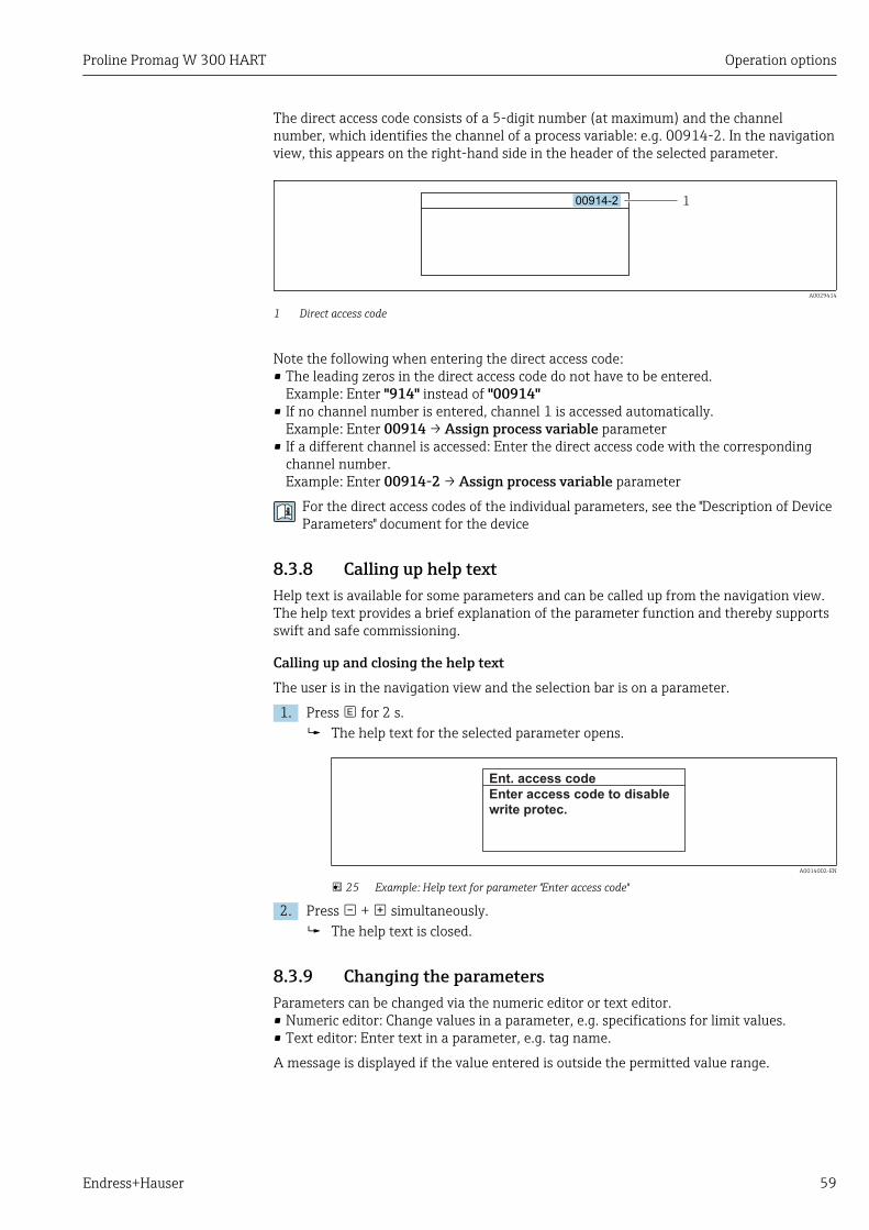
Proline Promag W 300 HART Operation options
Endress+Hauser 59
The direct access code consists of a 5-digit number (at maximum) and the channelnumber, which identifies the channel of a process variable: e.g. 00914-2. In the navigationview, this appears on the right-hand side in the header of the selected parameter.
100914-2
A0029414
1 Direct access code
Note the following when entering the direct access code:• The leading zeros in the direct access code do not have to be entered.
Example: Enter "914" instead of "00914"• If no channel number is entered, channel 1 is accessed automatically.
Example: Enter 00914 → Assign process variable parameter• If a different channel is accessed: Enter the direct access code with the corresponding
channel number.Example: Enter 00914-2 → Assign process variable parameter
For the direct access codes of the individual parameters, see the "Description of DeviceParameters" document for the device
8.3.8 Calling up help textHelp text is available for some parameters and can be called up from the navigation view.The help text provides a brief explanation of the parameter function and thereby supportsswift and safe commissioning.
Calling up and closing the help textThe user is in the navigation view and the selection bar is on a parameter.
1. Press for 2 s. The help text for the selected parameter opens.
Ent. access code
Enter access code to disable
write protec.
A0014002-EN
25 Example: Help text for parameter "Enter access code"
2. Press + simultaneously. The help text is closed.
8.3.9 Changing the parametersParameters can be changed via the numeric editor or text editor.• Numeric editor: Change values in a parameter, e.g. specifications for limit values.• Text editor: Enter text in a parameter, e.g. tag name.
A message is displayed if the value entered is outside the permitted value range.

Operation options Proline Promag W 300 HART
60 Endress+Hauser
Ent. access code
Invalid or out of range input
value
Max:9999
Min:0
A0014049-EN
For a description of the editing view - consisting of the text editor and numeric editor- with symbols → 54, for a description of the operating elements → 56
8.3.10 User roles and related access authorizationThe two user roles "Operator" and "Maintenance" have different write access to theparameters if the customer defines a user-specific access code. This protects the deviceconfiguration via the local display from unauthorized access → 117.
Defining access authorization for user rolesAn access code is not yet defined when the device is delivered from the factory. Accessauthorization (read and write access) to the device is not restricted and corresponds to the"Maintenance" user role.
‣ Define the access code. The "Operator" user role is redefined in addition to the "Maintenance" user role.
Access authorization differs for the two user roles.
Access authorization to parameters: "Maintenance" user role
Access code status Read access Write access
An access code has not yet been defined(factory setting).
After an access code has been defined. 1)
1) The user only has write access after entering the access code.
Access authorization to parameters: "Operator" user role
Access code status Read access Write access
After an access code has been defined. –– 1)
1) Despite the defined access code, certain parameters can always be modified and thus are excepted fromthe write protection, as they do not affect the measurement. Refer to the "Write protection via access code"section
The user role with which the user is currently logged on is indicated by the Accessstatus parameter. Navigation path: Operation → Access status
8.3.11 Disabling write protection via access codeIf the -symbol appears on the local display in front of a parameter, the parameter iswrite-protected by a user-specific access code and its value cannot be changed at themoment using local operation → 117.
Parameter write protection via local operation can be disabled by entering the user-specificaccess code in the Enter access code parameter (→ 104) via the respective accessoption.
1. After you press , the input prompt for the access code appears.
Proline Promag W 300 HART Operation options
Endress+Hauser 61
2. Enter the access code. The -symbol in front of the parameters disappears; all previously write-
protected parameters are now re-enabled.
8.3.12 Enabling and disabling the keypad lockThe keypad lock makes it possible to block access to the entire operating menu via localoperation. As a result, it is no longer possible to navigate through the operating menu orchange the values of individual parameters. Users can only read the measured values onthe operational display.
The keypad lock is switched on and off via the context menu.
Switching on the keypad lockThe keypad lock is switched on automatically:• If the device has not been operated via the display for > 1 minute.• Each time the device is restarted.
To activate the keylock manually:1. The device is in the measured value display.
Press the and keys for 3 seconds. A context menu appears.
2. In the context menu select the Keylock on option. The keypad lock is switched on.
If the user attempts to access the operating menu while the keypad lock is active, theKeylock on message appears.
Switching off the keypad lock
‣ The keypad lock is switched on.Press the and keys for 3 seconds. The keypad lock is switched off.
8.4 Access to the operating menu via the Web browser
8.4.1 Function rangeThanks to the integrated Web server, the device can be operated and configured via a Webbrowser and via a service interface (CDI-RJ45) or via a WLAN interface. The structure ofthe operating menu is the same as for the local display. In addition to the measured values,status information on the device is also displayed and allows the user to monitor the statusof the device. Furthermore the device data can be managed and the network parameterscan be configured.
A device that has a WLAN interface (can be ordered as an option) is required for theWLAN connection: order code for "Display; operation", option G "4-line, illuminated; touchcontrol + WLAN". The device acts as an Access Point and enables communication bycomputer or a mobile handheld terminal.
For additional information on the Web server, refer to the Special Documentation forthe device

Operation options Proline Promag W 300 HART
62 Endress+Hauser
8.4.2 Prerequisites
Computer hardware
Hardware Interface
CDI-RJ45 WLAN
Interface The computer must have an RJ45interface.
The operating unit must have aWLAN interface.
Connection Standard Ethernet cable with RJ45connector.
Connection via Wireless LAN.
Screen Recommended size: ≥12" (depends on the screen resolution)
Computer software
Software Interface
CDI-RJ45 WLAN
Recommended operatingsystems
• Microsoft Windows 7 or higher.• Mobile operating systems:
– iOS– Android
Microsoft Windows XP is supported.
Web browsers supported • Microsoft Internet Explorer 8 or higher• Microsoft Edge• Mozilla Firefox• Google Chrome• Safari
Computer settings
Settings Interface
CDI-RJ45 WLAN
User rights Appropriate user rights (e.g. administrator rights) for TCP/IP and proxy serversettings are necessary (for adjusting the IP address, subnet mask etc.).
Proxy server settings of theWeb browser
The Web browser setting Use a Proxy Server for Your LAN must bedeselected .
JavaScript JavaScript must be enabled.
If JavaScript cannot be enabled:enter http://192.168.1.212/basic.html in the address line of the Webbrowser. A fully functional but simplified version of the operating menustructure starts in the Web browser.
When installing a new firmware version: To enable correct data display,clear the temporary memory (cache) of the Web browser under Internetoptions.
Network connections Only the active network connections to the measuring device should be used.
Switch off all other networkconnections such as WLAN.
Switch off all other networkconnections.
In the event of connection problems: → 131
Proline Promag W 300 HART Operation options
Endress+Hauser 63
Measuring device: Via CDI-RJ45 service interface
Device CDI-RJ45 service interface
Measuring device The measuring device has an RJ45 interface.
Web server Web server must be enabled; factory setting: ON
For information on enabling the Web server → 67
Measuring device: via WLAN interface
Device WLAN interface
Measuring device The measuring device has a WLAN antenna:• Transmitter with integrated WLAN antenna• Transmitter with external WLAN antenna
Web server Web server and WLAN must be enabled; factory setting: ON
For information on enabling the Web server → 67
8.4.3 Establishing a connection
Via service interface (CDI-RJ45)Preparing the measuring device
1. Depending on the housing version:Release the securing clamp or securing screw of the housing cover.
2. Depending on the housing version:Unscrew or open the housing cover.
3. The location of the connection socket depends on the measuring device and thecommunication protocol:Connect the computer to the RJ45 connector via the standard Ethernet connectingcable .
Configuring the Internet protocol of the computer
The following information refers to the default Ethernet settings of the device.
IP address of the device: 192.168.1.212 (factory setting)
1. Switch on the measuring device.
2. Connect to the computer using a cable → 69.
3. If a 2nd network card is not used, close all the applications on the notebook. Applications requiring Internet or a network, such as e-mail, SAP applications,
Internet or Windows Explorer.
4. Close any open Internet browsers.
5. Configure the properties of the Internet protocol (TCP/IP) as defined in the table:
IP address 192.168.1.XXX; for XXX all numerical sequences except: 0, 212 and 255 → e.g.192.168.1.213
Subnet mask 255.255.255.0
Default gateway 192.168.1.212 or leave cells empty
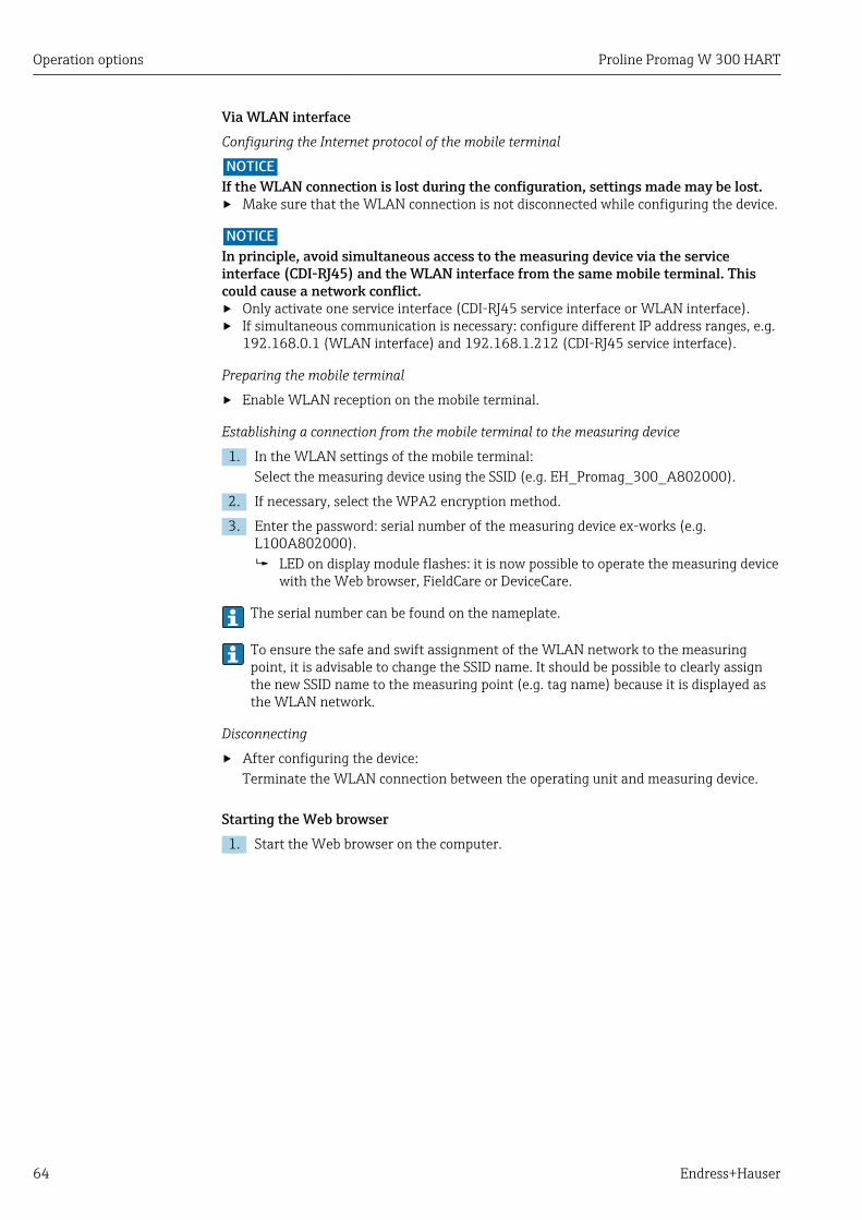
Operation options Proline Promag W 300 HART
64 Endress+Hauser
Via WLAN interfaceConfiguring the Internet protocol of the mobile terminal
NOTICEIf the WLAN connection is lost during the configuration, settings made may be lost.‣ Make sure that the WLAN connection is not disconnected while configuring the device.
NOTICEIn principle, avoid simultaneous access to the measuring device via the serviceinterface (CDI-RJ45) and the WLAN interface from the same mobile terminal. Thiscould cause a network conflict.‣ Only activate one service interface (CDI-RJ45 service interface or WLAN interface).‣ If simultaneous communication is necessary: configure different IP address ranges, e.g.
192.168.0.1 (WLAN interface) and 192.168.1.212 (CDI-RJ45 service interface).
Preparing the mobile terminal
‣ Enable WLAN reception on the mobile terminal.
Establishing a connection from the mobile terminal to the measuring device
1. In the WLAN settings of the mobile terminal:Select the measuring device using the SSID (e.g. EH_Promag_300_A802000).
2. If necessary, select the WPA2 encryption method.
3. Enter the password: serial number of the measuring device ex-works (e.g.L100A802000). LED on display module flashes: it is now possible to operate the measuring device
with the Web browser, FieldCare or DeviceCare.
The serial number can be found on the nameplate.
To ensure the safe and swift assignment of the WLAN network to the measuringpoint, it is advisable to change the SSID name. It should be possible to clearly assignthe new SSID name to the measuring point (e.g. tag name) because it is displayed asthe WLAN network.
Disconnecting
‣ After configuring the device:Terminate the WLAN connection between the operating unit and measuring device.
Starting the Web browser1. Start the Web browser on the computer.
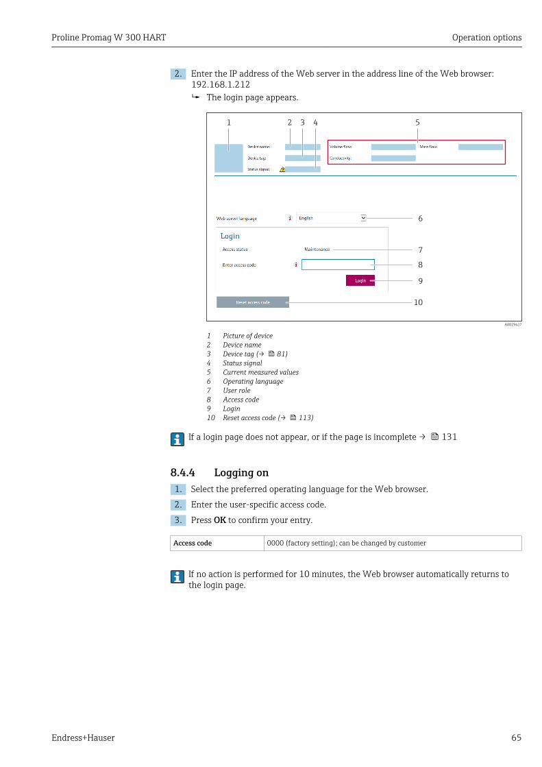
Proline Promag W 300 HART Operation options
Endress+Hauser 65
2. Enter the IP address of the Web server in the address line of the Web browser:192.168.1.212 The login page appears.
6
7
8
9
10
1 52 3 4
A0029417
1 Picture of device2 Device name3 Device tag (→ 81)4 Status signal5 Current measured values6 Operating language7 User role8 Access code9 Login10 Reset access code (→ 113)
If a login page does not appear, or if the page is incomplete → 131
8.4.4 Logging on1. Select the preferred operating language for the Web browser.
2. Enter the user-specific access code.
3. Press OK to confirm your entry.
Access code 0000 (factory setting); can be changed by customer
If no action is performed for 10 minutes, the Web browser automatically returns tothe login page.

Operation options Proline Promag W 300 HART
66 Endress+Hauser
8.4.5 User interface
2
1
3
A0029418
1 Function row2 Local display language3 Navigation area
HeaderThe following information appears in the header:• Device name• Device tag• Device status with status signal → 137• Current measured values
Function row
Functions Meaning
Measured values Displays the measured values of the measuring device
Menu
• Access to the operating menu from the measuring device• The structure of the operating menu is the same as for the local display
For detailed information on the structure of the operating menu, see the OperatingInstructions for the measuring device
Device status Displays the diagnostic messages currently pending, listed in order of priority
Datamanagement
Data exchange between PC and measuring device:• Device configuration:
– Load settings from the device(XML format, save configuration)
– Save settings to the device(XML format, restore configuration)
• Logbook - Export Event logbook (.csv file)• Documents - Export documents:
– Export backup data record(.csv file, create documentation of the measuring point configuration)
– Verification report(PDF file, only available with the "Heartbeat Verification" application package)
• Firmware update - Flashing a firmware version
Networkconfiguration
Configuration and checking of all the parameters required for establishing the connectionto the measuring device:• Network settings (e.g. IP address, MAC address)• Device information (e.g. serial number, firmware version)
Logout End the operation and call up the login page
Navigation areaIf a function is selected in the function bar, the submenus of the function open in thenavigation area. The user can now navigate through the menu structure.
Proline Promag W 300 HART Operation options
Endress+Hauser 67
Working areaDepending on the selected function and the related submenus, various actions can beperformed in this area:• Configuring parameters• Reading measured values• Calling up help text• Starting an upload/download
8.4.6 Disabling the Web serverThe Web server of the measuring device can be switched on and off as required using theWeb server functionality parameter.
Navigation"Expert" menu → Communication → Web server
Parameter overview with brief description
Parameter Description Selection Factory setting
Web server functionality Switch the Web server on and off. • Off• HTML Off• On
On
Function scope of the "Web server functionality" parameter
Option Description
Off • The web server is completely disabled.• Port 80 is locked.
On • The complete functionality of the web server is available.• JavaScript is used.• The password is transferred in an encrypted state.• Any change to the password is also transferred in an encrypted state.
Enabling the Web serverIf the Web server is disabled it can only be re-enabled with the Web server functionalityparameter via the following operating options:• Via local display• Via Bedientool "FieldCare"• Via "DeviceCare" operating tool
8.4.7 Logging outBefore logging out, perform a data backup via the Data management function(upload configuration from device) if necessary.
1. Select the Logout entry in the function row. The home page with the Login box appears.
2. Close the Web browser.
3. If no longer needed:Reset modified properties of the Internet protocol (TCP/IP) → 63.

Operation options Proline Promag W 300 HART
68 Endress+Hauser
8.5 Access to the operating menu via the operating toolThe structure of the operating menu in the operating tools is the same as for operation viathe local display.
8.5.1 Connecting the operating tool
Via HART protocolThis communication interface is available in device versions with a HART output.
1 2 3 5
8
4 7
6
A0028747
26 Options for remote operation via HART protocol (active)
1 Control system (e.g. PLC)2 Field Communicator 4753 Computer with Web browser (e.g. Internet Explorer) for access to the integrated device Web server or
computer with an operating tool (e.g. FieldCare, DeviceCare, AMS Device Manager, SIMATIC PDM) with COMDTM "CDI Communication TCP/IP"
4 Commubox FXA195 (USB)5 Field Xpert SFX350 or SFX3706 Field Xpert SMT707 VIATOR Bluetooth modem with connecting cable8 Transmitter
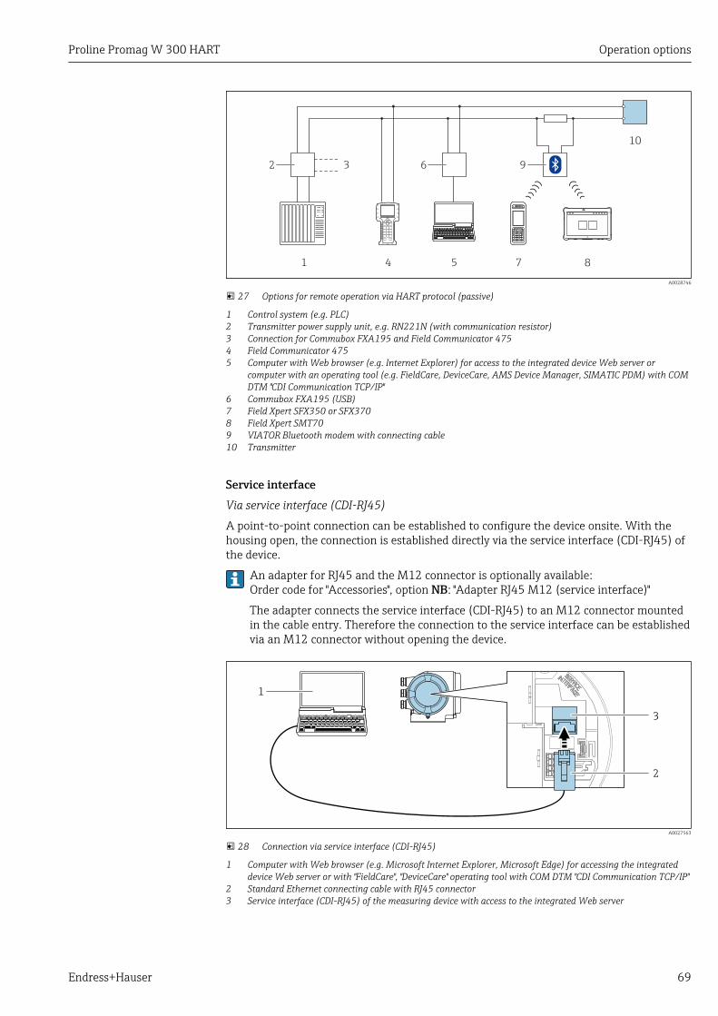
Proline Promag W 300 HART Operation options
Endress+Hauser 69
1
10
2 3
4 5 7
6 9
8
A0028746
27 Options for remote operation via HART protocol (passive)
1 Control system (e.g. PLC)2 Transmitter power supply unit, e.g. RN221N (with communication resistor)3 Connection for Commubox FXA195 and Field Communicator 4754 Field Communicator 4755 Computer with Web browser (e.g. Internet Explorer) for access to the integrated device Web server or
computer with an operating tool (e.g. FieldCare, DeviceCare, AMS Device Manager, SIMATIC PDM) with COMDTM "CDI Communication TCP/IP"
6 Commubox FXA195 (USB)7 Field Xpert SFX350 or SFX3708 Field Xpert SMT709 VIATOR Bluetooth modem with connecting cable10 Transmitter
Service interfaceVia service interface (CDI-RJ45)
A point-to-point connection can be established to configure the device onsite. With thehousing open, the connection is established directly via the service interface (CDI-RJ45) ofthe device.
An adapter for RJ45 and the M12 connector is optionally available:Order code for "Accessories", option NB: "Adapter RJ45 M12 (service interface)"
The adapter connects the service interface (CDI-RJ45) to an M12 connector mountedin the cable entry. Therefore the connection to the service interface can be establishedvia an M12 connector without opening the device.
2
3
1
A0027563
28 Connection via service interface (CDI-RJ45)
1 Computer with Web browser (e.g. Microsoft Internet Explorer, Microsoft Edge) for accessing the integrateddevice Web server or with "FieldCare", "DeviceCare" operating tool with COM DTM "CDI Communication TCP/IP"
2 Standard Ethernet connecting cable with RJ45 connector3 Service interface (CDI-RJ45) of the measuring device with access to the integrated Web server

Operation options Proline Promag W 300 HART
70 Endress+Hauser
Via WLAN interface
The optional WLAN interface is available on the following device version:Order code for "Display; operation", option G "4-line, illuminated; touch control + WLAN"
213 4 3 4
5 6 7
A0034570
1 Transmitter with integrated WLAN antenna2 Transmitter with external WLAN antenna3 LED lit constantly: WLAN reception is enabled on measuring device4 LED flashing: WLAN connection established between operating unit and measuring device5 Computer with WLAN interface and Web browser (e.g. Microsoft Internet Explorer, Microsoft Edge) for
accessing the integrated device Web server or with operating tool (e.g. FieldCare, DeviceCare)6 Mobile handheld terminal with WLAN interface and Web browser (e.g. Microsoft Internet Explorer, Microsoft
Edge) for accessing the integrated device Web server or operating tool (e.g. FieldCare, DeviceCare)7 Smart phone or tablet (e.g. Field Xpert SMT70)
Function WLAN: IEEE 802.11 b/g (2.4 GHz)
Encryption WPA2-PSK AES-128 (in accordance with IEEE 802.11i)
Configurable WLAN channels 1 to 11
Degree of protection IP67
Available antennas • Internal antenna• External antenna (optional)
In the event of poor transmission/reception conditions at the place ofinstallation.
Only one antenna active in each case!
Range • Internal antenna: typically 10 m (32 ft)• External antenna: typically 50 m (164 ft)
Materials (external antenna) • Antenna: ASA plastic (acrylic ester-styrene-acrylonitrile) and nickel-plated brass
• Adapter: Stainless steel and nickel-plated brass• Cable: Polyethylene• Connector: Nickel-plated brass• Angle bracket: Stainless steel
Configuring the Internet protocol of the mobile terminal
NOTICEIf the WLAN connection is lost during the configuration, settings made may be lost.‣ Make sure that the WLAN connection is not disconnected while configuring the device.
Proline Promag W 300 HART Operation options
Endress+Hauser 71
NOTICEIn principle, avoid simultaneous access to the measuring device via the serviceinterface (CDI-RJ45) and the WLAN interface from the same mobile terminal. Thiscould cause a network conflict.‣ Only activate one service interface (CDI-RJ45 service interface or WLAN interface).‣ If simultaneous communication is necessary: configure different IP address ranges, e.g.
192.168.0.1 (WLAN interface) and 192.168.1.212 (CDI-RJ45 service interface).
Preparing the mobile terminal
‣ Enable WLAN reception on the mobile terminal.
Establishing a connection from the mobile terminal to the measuring device
1. In the WLAN settings of the mobile terminal:Select the measuring device using the SSID (e.g. EH_Promag_300_A802000).
2. If necessary, select the WPA2 encryption method.
3. Enter the password: serial number of the measuring device ex-works (e.g.L100A802000). LED on display module flashes: it is now possible to operate the measuring device
with the Web browser, FieldCare or DeviceCare.
The serial number can be found on the nameplate.
To ensure the safe and swift assignment of the WLAN network to the measuringpoint, it is advisable to change the SSID name. It should be possible to clearly assignthe new SSID name to the measuring point (e.g. tag name) because it is displayed asthe WLAN network.
Disconnecting
‣ After configuring the device:Terminate the WLAN connection between the operating unit and measuring device.
8.5.2 Field Xpert SFX350, SFX370
Function rangeField Xpert SFX350 and Field Xpert SFX370 are mobile computers for commissioning andmaintenance. They enable efficient device configuration and diagnostics for HART andFOUNDATION Fieldbus devices in the non-hazardous area (SFX350, SFX370) andhazardous area (SFX370).
For details, see Operating Instructions BA01202S
Source for device description filesSee information → 75
8.5.3 FieldCare
Function scopeFDT-based plant asset management tool from Endress+Hauser. It can configure all smartfield devices in a system and helps you manage them. By using the status information, it isalso a simple but effective way of checking their status and condition.
Operation options Proline Promag W 300 HART
72 Endress+Hauser
Access is via:• HART protocol• CDI-RJ45 service interface → 69• WLAN interface→ 70
Typical functions:• Configuring parameters of transmitters• Loading and saving device data (upload/download)• Documentation of the measuring point• Visualization of the measured value memory (line recorder) and event logbook
For additional information about FieldCare, see Operating Instructions BA00027Sand BA00059S
Source for device description filesSee information → 75
Establishing a connection1. Start FieldCare and launch the project.
2. In the network: Add a device. The Add device window opens.
3. Select the CDI Communication TCP/IP option from the list and press OK to confirm.
4. Right-click CDI Communication TCP/IP and select the Add device option in thecontext menu that opens.
5. Select the desired device from the list and press OK to confirm. The CDI Communication TCP/IP (Configuration) window opens.
6. Enter the device address in the IP address field: 192.168.1.212 and press Enter toconfirm.
7. Establish the online connection to the device.
For additional information, see Operating Instructions BA00027S and BA00059S

Proline Promag W 300 HART Operation options
Endress+Hauser 73
User interface
6532
1
Xxxxxx/…/…/
7
P
P
+
–
P
–
P
+
+
+
+
+
+
4
8 9
10 11
Xxxxxxx
GoodStatus:
Device tag:
XxxxxxxDevice name: Mass flow: 12.34 kg/h
Volume flow: 12.34 m /h³
Mass flow unit:
Volume flow unit:
kg/h
m /h³Access status tooling
Operation
Setup
Xxxxxx
Mass flow unitVolume flow unit
Select medium
Device tag
…
…
Advanced setup
Diagnostics
Expert
Maintenance
kg/hm /h³
Xxxxxx
System units
A0021051-EN
1 Header2 Picture of device3 Device name4 Device tag5 Status area with status signal→ 1376 Display area for current measured values7 Edit toolbar with additional functions such as save/restore, event list and create documentation8 Navigation area with operating menu structure9 Working area10 Range of action11 Status area
8.5.4 DeviceCare
Function scopeTool to connect and configure Endress+Hauser field devices.
The fastest way to configure Endress+Hauser field devices is with the dedicated"DeviceCare" tool. Together with the device type managers (DTMs) it presents a convenient,comprehensive solution.
For details, see Innovation Brochure IN01047S
Source for device description filesSee information → 75
8.5.5 AMS Device Manager
Function scopeProgram from Emerson Process Management for operating and configuring measuringdevices via HART protocol.

Operation options Proline Promag W 300 HART
74 Endress+Hauser
Source for device description filesSee data → 75
8.5.6 SIMATIC PDM
Function scopeSIMATIC PDM is a standardized, manufacturer-independent program from Siemens forthe operation, configuration, maintenance and diagnosis of intelligent field devices viaHART protocol.
Source for device description filesSee data → 75
8.5.7 Field Communicator 475
Function scopeIndustrial handheld terminal from Emerson Process Management for remoteconfiguration and measured value display via HART protocol.
Source for device description filesSee data → 75
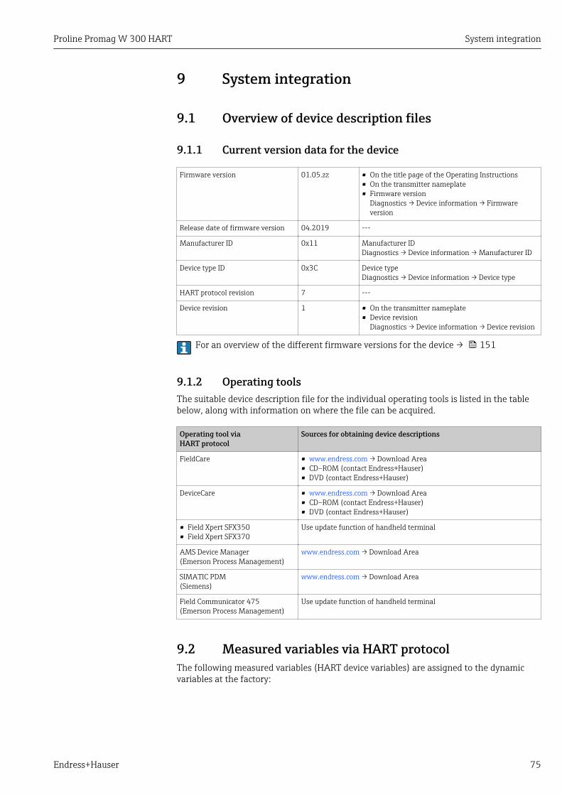
Proline Promag W 300 HART System integration
Endress+Hauser 75
9 System integration
9.1 Overview of device description files
9.1.1 Current version data for the device
Firmware version 01.05.zz • On the title page of the Operating Instructions• On the transmitter nameplate• Firmware version
Diagnostics → Device information → Firmwareversion
Release date of firmware version 04.2019 ---
Manufacturer ID 0x11 Manufacturer IDDiagnostics → Device information → Manufacturer ID
Device type ID 0x3C Device typeDiagnostics → Device information → Device type
HART protocol revision 7 ---
Device revision 1 • On the transmitter nameplate• Device revision
Diagnostics → Device information → Device revision
For an overview of the different firmware versions for the device → 151
9.1.2 Operating toolsThe suitable device description file for the individual operating tools is listed in the tablebelow, along with information on where the file can be acquired.
Operating tool viaHART protocol
Sources for obtaining device descriptions
FieldCare • www.endress.com → Download Area• CD–ROM (contact Endress+Hauser)• DVD (contact Endress+Hauser)
DeviceCare • www.endress.com → Download Area• CD–ROM (contact Endress+Hauser)• DVD (contact Endress+Hauser)
• Field Xpert SFX350• Field Xpert SFX370
Use update function of handheld terminal
AMS Device Manager(Emerson Process Management)
www.endress.com → Download Area
SIMATIC PDM(Siemens)
www.endress.com → Download Area
Field Communicator 475(Emerson Process Management)
Use update function of handheld terminal
9.2 Measured variables via HART protocolThe following measured variables (HART device variables) are assigned to the dynamicvariables at the factory:
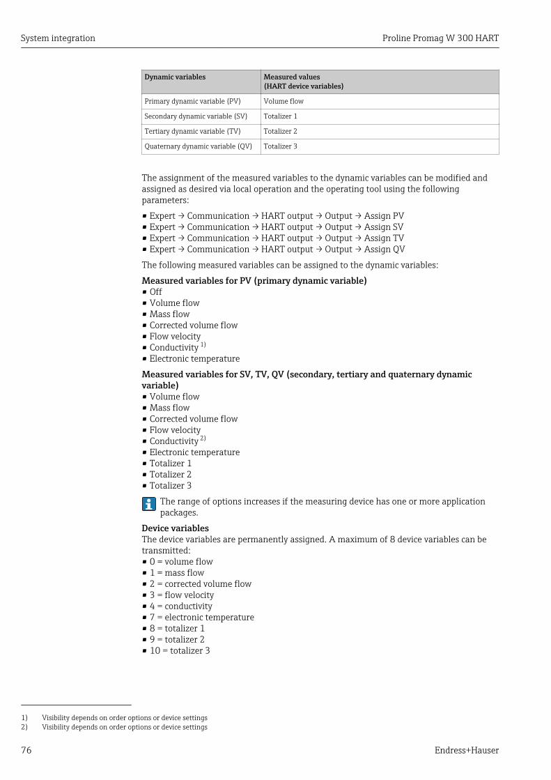
System integration Proline Promag W 300 HART
76 Endress+Hauser
Dynamic variables Measured values(HART device variables)
Primary dynamic variable (PV) Volume flow
Secondary dynamic variable (SV) Totalizer 1
Tertiary dynamic variable (TV) Totalizer 2
Quaternary dynamic variable (QV) Totalizer 3
The assignment of the measured variables to the dynamic variables can be modified andassigned as desired via local operation and the operating tool using the followingparameters:
• Expert → Communication → HART output → Output → Assign PV• Expert → Communication → HART output → Output → Assign SV• Expert → Communication → HART output → Output → Assign TV• Expert → Communication → HART output → Output → Assign QV
The following measured variables can be assigned to the dynamic variables:
Measured variables for PV (primary dynamic variable)• Off• Volume flow• Mass flow• Corrected volume flow• Flow velocity• Conductivity 1)
• Electronic temperature
Measured variables for SV, TV, QV (secondary, tertiary and quaternary dynamicvariable)• Volume flow• Mass flow• Corrected volume flow• Flow velocity• Conductivity 2)
• Electronic temperature• Totalizer 1• Totalizer 2• Totalizer 3
The range of options increases if the measuring device has one or more applicationpackages.
Device variablesThe device variables are permanently assigned. A maximum of 8 device variables can betransmitted:• 0 = volume flow• 1 = mass flow• 2 = corrected volume flow• 3 = flow velocity• 4 = conductivity• 7 = electronic temperature• 8 = totalizer 1• 9 = totalizer 2• 10 = totalizer 3
1) Visibility depends on order options or device settings2) Visibility depends on order options or device settings

Proline Promag W 300 HART System integration
Endress+Hauser 77
9.3 Other settingsBurst mode functionality in accordance with HART 7 Specification:
Navigation"Expert" menu → Communication → HART output → Burst configuration → Burstconfiguration 1 to n
‣ Burst configuration
‣ Burst configuration 1 to n
Burst mode 1 to n → 77
Burst command 1 to n → 77
Burst variable 0 → 78
Burst variable 1 → 78
Burst variable 2 → 78
Burst variable 3 → 78
Burst variable 4 → 78
Burst variable 5 → 78
Burst variable 6 → 78
Burst variable 7 → 78
Burst trigger mode → 78
Burst trigger level → 78
Min. update period → 78
Max. update period → 78
Parameter overview with brief description
Parameter Description Selection / User entry Factory setting
Burst mode 1 to n Activate the HART burst mode for burstmessage X.
• Off• On
Off
Burst command 1 to n Select the HART command that is sent to theHART master.
• Command 1• Command 2• Command 3• Command 9• Command 33• Command 48
Command 2

System integration Proline Promag W 300 HART
78 Endress+Hauser
Parameter Description Selection / User entry Factory setting
Burst variable 0 For HART command 9 and 33: select theHART device variable or the process variable.
• Volume flow• Mass flow• Corrected volume flow• Flow velocity• Conductivity *
• Electronic temperature• Totalizer 1• Totalizer 2• Totalizer 3• Density• HART input• Percent of range• Measured current• Primary variable (PV)• Secondary variable (SV)• Tertiary variable (TV)• Quaternary variable (QV)• Not used
Volume flow
Burst variable 1 For HART command 9 and 33: select theHART device variable or the process variable.
See the Burst variable 0parameter.
Not used
Burst variable 2 For HART command 9 and 33: select theHART device variable or the process variable.
See the Burst variable 0parameter.
Not used
Burst variable 3 For HART command 9 and 33: select theHART device variable or the process variable.
See the Burst variable 0parameter.
Not used
Burst variable 4 For HART command 9: select the HARTdevice variable or the process variable.
See the Burst variable 0parameter.
Not used
Burst variable 5 For HART command 9: select the HARTdevice variable or the process variable.
See the Burst variable 0parameter.
Not used
Burst variable 6 For HART command 9: select the HARTdevice variable or the process variable.
See the Burst variable 0parameter.
Not used
Burst variable 7 For HART command 9: select the HARTdevice variable or the process variable.
See the Burst variable 0parameter.
Not used
Burst trigger mode Select the event that triggers burst messageX.
• Continuous• Window• Rising• Falling• On change
Continuous
Burst trigger level Enter the burst trigger value.
Together with the option selected in theBurst trigger mode parameter the bursttrigger value determines the time of burstmessage X.
Signed floating-point number –
Min. update period Enter the minimum time span between twoburst commands of burst message X.
Positive integer 1 000 ms
Max. update period Enter the maximum time span between twoburst commands of burst message X.
Positive integer 2 000 ms
* Visibility depends on order options or device settings
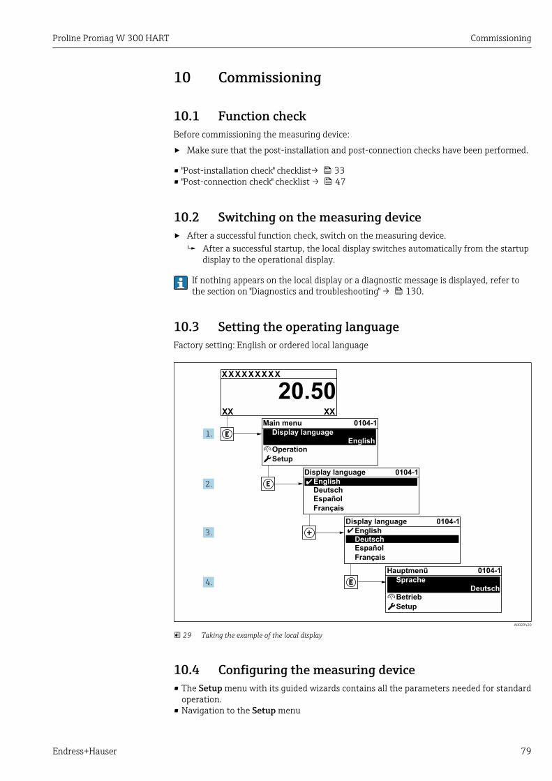
Proline Promag W 300 HART Commissioning
Endress+Hauser 79
10 Commissioning
10.1 Function checkBefore commissioning the measuring device:
‣ Make sure that the post-installation and post-connection checks have been performed.
• "Post-installation check" checklist→ 33• "Post-connection check" checklist → 47
10.2 Switching on the measuring device‣ After a successful function check, switch on the measuring device.
After a successful startup, the local display switches automatically from the startupdisplay to the operational display.
If nothing appears on the local display or a diagnostic message is displayed, refer tothe section on "Diagnostics and troubleshooting" → 130.
10.3 Setting the operating languageFactory setting: English or ordered local language
X X X X X X XX X
20.50
Operation
Setup
Main menu 0104-1
Display languageEnglish
Español
Français
Display language
EnglishDeutsch
Ã
0104-1
Ã
Español
Français
Display language
EnglishDeutsch
0104-1
Betrieb
Setup
Hauptmenü
SpracheDeutsch
0104-1
XXXX
1.
2.
3.
4.
A0029420
29 Taking the example of the local display
10.4 Configuring the measuring device• The Setup menu with its guided wizards contains all the parameters needed for standard
operation.• Navigation to the Setup menu
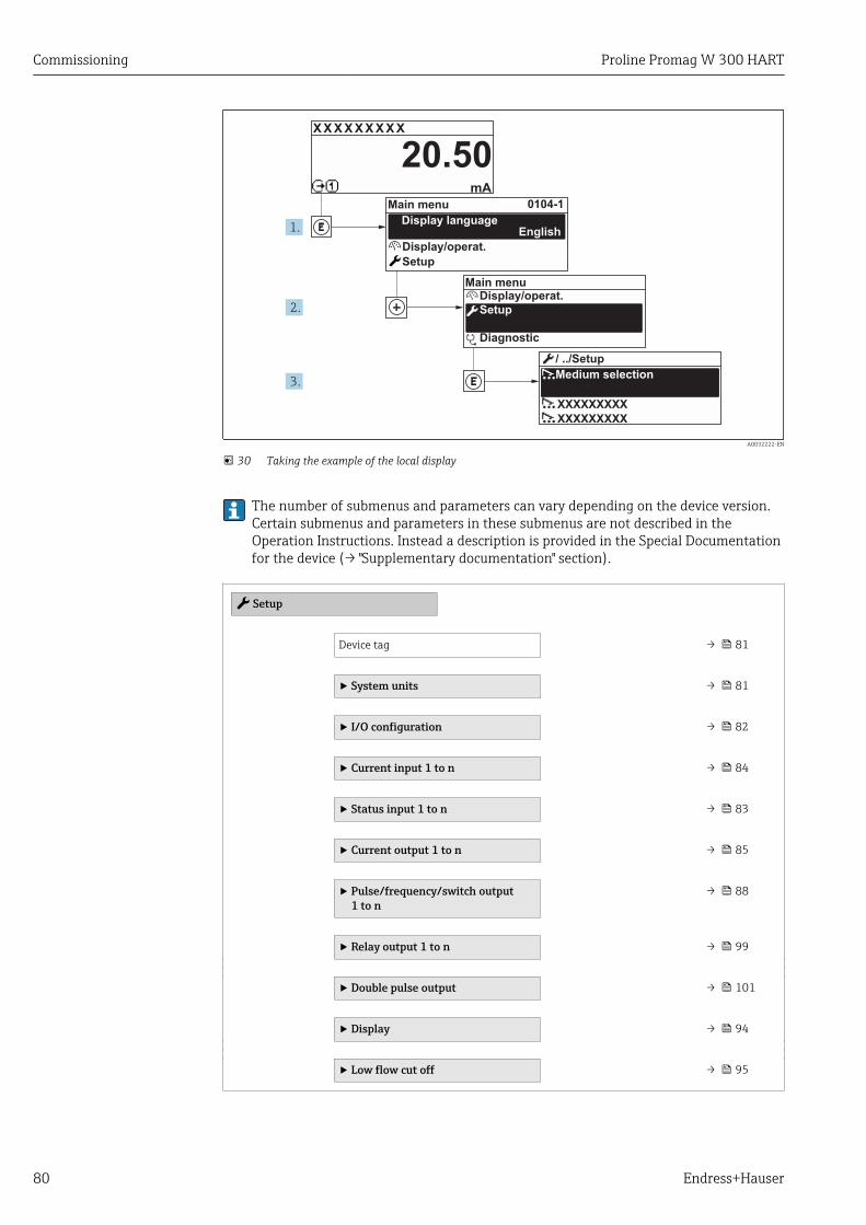
Commissioning Proline Promag W 300 HART
80 Endress+Hauser
X X X X X X XX X
20.500104-1
XXXXXXXXX
XXXXXXXXX
mA
1.
2.
3.
Display/operat.
Setup
Diagnostic
Display/operat.
Setup
Main menu
English
Main menu
Medium selection
/ ../Setup
Display language
A0032222-EN
30 Taking the example of the local display
The number of submenus and parameters can vary depending on the device version.Certain submenus and parameters in these submenus are not described in theOperation Instructions. Instead a description is provided in the Special Documentationfor the device (→ "Supplementary documentation" section).
Setup
Device tag → 81
‣ System units → 81
‣ I/O configuration → 82
‣ Current input 1 to n → 84
‣ Status input 1 to n → 83
‣ Current output 1 to n → 85
‣ Pulse/frequency/switch output1 to n
→ 88
‣ Relay output 1 to n → 99
‣ Double pulse output → 101
‣ Display → 94
‣ Low flow cut off → 95

Proline Promag W 300 HART Commissioning
Endress+Hauser 81
‣ Empty pipe detection → 97
‣ Advanced setup → 103
10.4.1 Defining the tag nameTo enable fast identification of the measuring point within the system, you can enter aunique designation using the Device tag parameter and thus change the factory setting.
1 XXXXXXXXX
A0029422
31 Header of the operational display with tag name
1 Tag name
Enter the tag name in the "FieldCare" operating tool → 73
Navigation"Setup" menu → Device tag
Parameter overview with brief description
Parameter Description User entry Factory setting
Device tag Enter the name for the measuring point. Max. 32 characters, such asletters, numbers or specialcharacters (e.g. @, %, /).
Promag
10.4.2 Setting the system unitsIn the System units submenu the units of all the measured values can be set.
Depending on the device version, not all submenus and parameters are available inevery device. The selection can vary depending on the order code.
Navigation"Setup" menu → System units
‣ System units
Volume flow unit → 82
Volume unit → 82
Conductivity unit
Temperature unit → 82
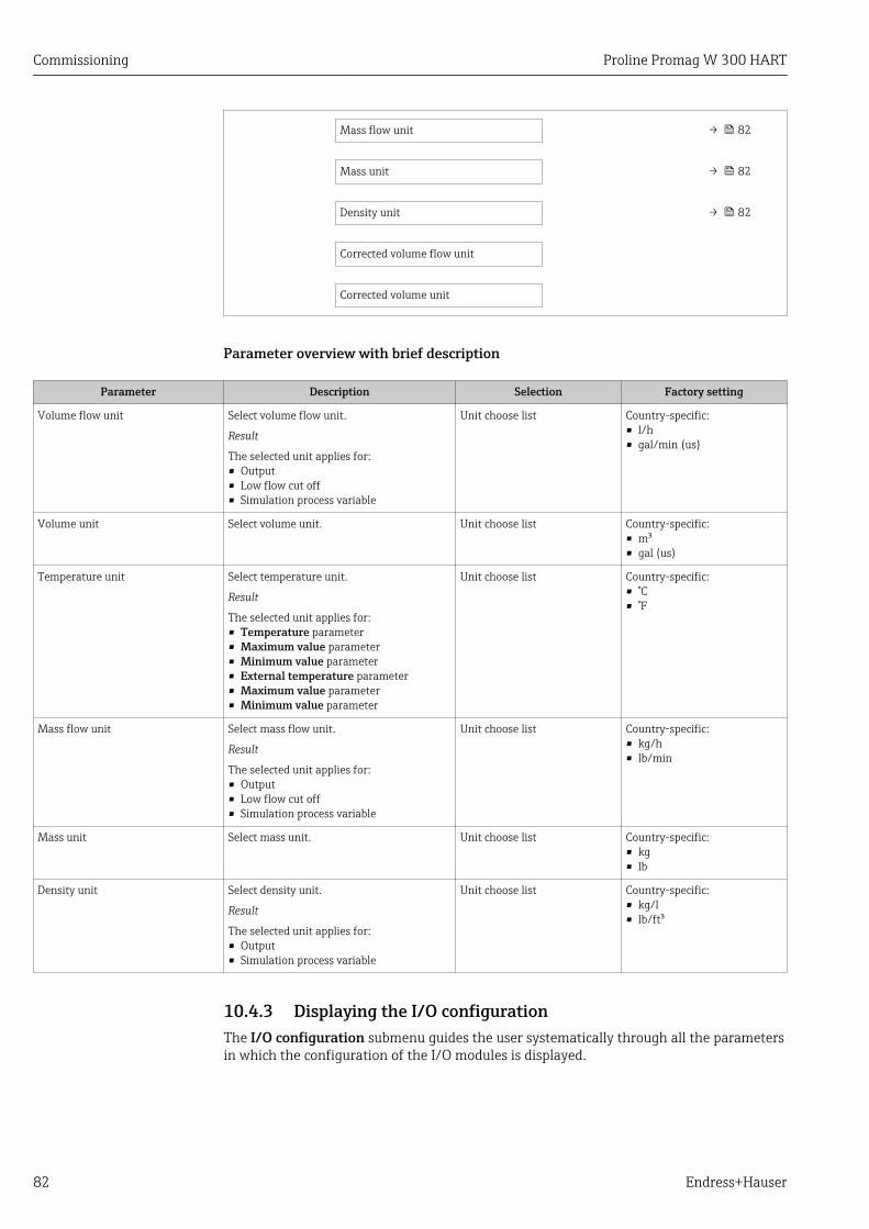
Commissioning Proline Promag W 300 HART
82 Endress+Hauser
Mass flow unit → 82
Mass unit → 82
Density unit → 82
Corrected volume flow unit
Corrected volume unit
Parameter overview with brief description
Parameter Description Selection Factory setting
Volume flow unit Select volume flow unit.
Result
The selected unit applies for:• Output• Low flow cut off• Simulation process variable
Unit choose list Country-specific:• l/h• gal/min (us)
Volume unit Select volume unit. Unit choose list Country-specific:• m³• gal (us)
Temperature unit Select temperature unit.
Result
The selected unit applies for:• Temperature parameter• Maximum value parameter• Minimum value parameter• External temperature parameter• Maximum value parameter• Minimum value parameter
Unit choose list Country-specific:• °C• °F
Mass flow unit Select mass flow unit.
Result
The selected unit applies for:• Output• Low flow cut off• Simulation process variable
Unit choose list Country-specific:• kg/h• lb/min
Mass unit Select mass unit. Unit choose list Country-specific:• kg• lb
Density unit Select density unit.
Result
The selected unit applies for:• Output• Simulation process variable
Unit choose list Country-specific:• kg/l• lb/ft³
10.4.3 Displaying the I/O configurationThe I/O configuration submenu guides the user systematically through all the parametersin which the configuration of the I/O modules is displayed.
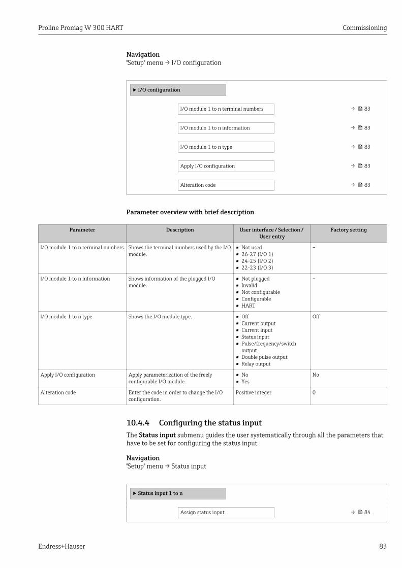
Proline Promag W 300 HART Commissioning
Endress+Hauser 83
Navigation"Setup" menu → I/O configuration
‣ I/O configuration
I/O module 1 to n terminal numbers → 83
I/O module 1 to n information → 83
I/O module 1 to n type → 83
Apply I/O configuration → 83
Alteration code → 83
Parameter overview with brief description
Parameter Description User interface / Selection / User entry
Factory setting
I/O module 1 to n terminal numbers Shows the terminal numbers used by the I/Omodule.
• Not used• 26-27 (I/O 1)• 24-25 (I/O 2)• 22-23 (I/O 3)
–
I/O module 1 to n information Shows information of the plugged I/Omodule.
• Not plugged• Invalid• Not configurable• Configurable• HART
–
I/O module 1 to n type Shows the I/O module type. • Off• Current output• Current input• Status input• Pulse/frequency/switch
output• Double pulse output• Relay output
Off
Apply I/O configuration Apply parameterization of the freelyconfigurable I/O module.
• No• Yes
No
Alteration code Enter the code in order to change the I/Oconfiguration.
Positive integer 0
10.4.4 Configuring the status inputThe Status input submenu guides the user systematically through all the parameters thathave to be set for configuring the status input.
Navigation"Setup" menu → Status input
‣ Status input 1 to n
Assign status input → 84
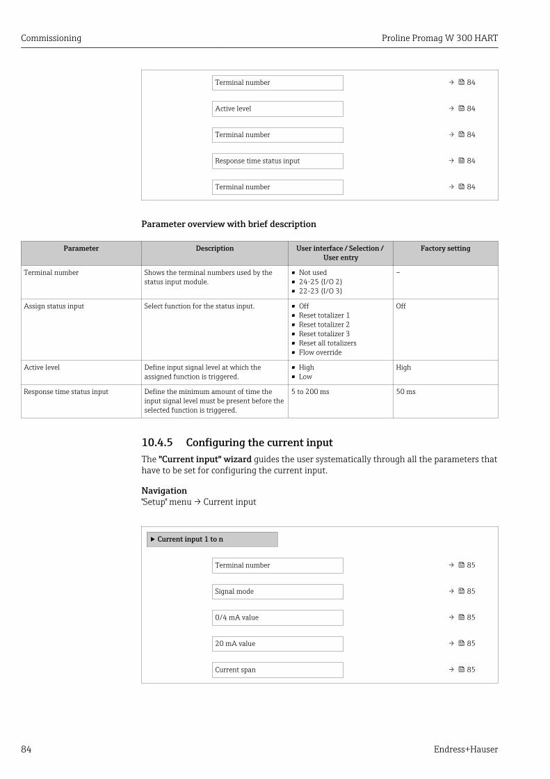
Commissioning Proline Promag W 300 HART
84 Endress+Hauser
Terminal number → 84
Active level → 84
Terminal number → 84
Response time status input → 84
Terminal number → 84
Parameter overview with brief description
Parameter Description User interface / Selection / User entry
Factory setting
Terminal number Shows the terminal numbers used by thestatus input module.
• Not used• 24-25 (I/O 2)• 22-23 (I/O 3)
–
Assign status input Select function for the status input. • Off• Reset totalizer 1• Reset totalizer 2• Reset totalizer 3• Reset all totalizers• Flow override
Off
Active level Define input signal level at which theassigned function is triggered.
• High• Low
High
Response time status input Define the minimum amount of time theinput signal level must be present before theselected function is triggered.
5 to 200 ms 50 ms
10.4.5 Configuring the current inputThe "Current input" wizard guides the user systematically through all the parameters thathave to be set for configuring the current input.
Navigation"Setup" menu → Current input
‣ Current input 1 to n
Terminal number → 85
Signal mode → 85
0/4 mA value → 85
20 mA value → 85
Current span → 85
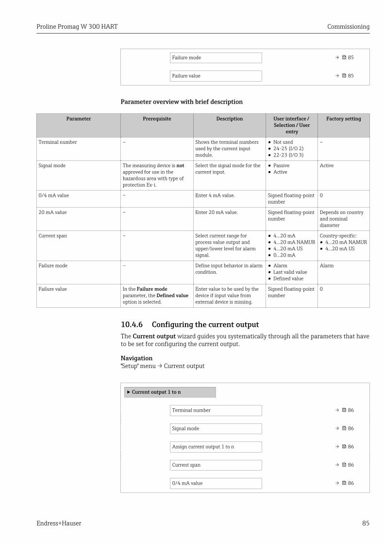
Proline Promag W 300 HART Commissioning
Endress+Hauser 85
Failure mode → 85
Failure value → 85
Parameter overview with brief description
Parameter Prerequisite Description User interface / Selection / User
entry
Factory setting
Terminal number – Shows the terminal numbersused by the current inputmodule.
• Not used• 24-25 (I/O 2)• 22-23 (I/O 3)
–
Signal mode The measuring device is notapproved for use in thehazardous area with type ofprotection Ex-i.
Select the signal mode for thecurrent input.
• Passive• Active
Active
0/4 mA value – Enter 4 mA value. Signed floating-pointnumber
0
20 mA value – Enter 20 mA value. Signed floating-pointnumber
Depends on countryand nominaldiameter
Current span – Select current range forprocess value output andupper/lower level for alarmsignal.
• 4...20 mA• 4...20 mA NAMUR• 4...20 mA US• 0...20 mA
Country-specific:• 4...20 mA NAMUR• 4...20 mA US
Failure mode – Define input behavior in alarmcondition.
• Alarm• Last valid value• Defined value
Alarm
Failure value In the Failure modeparameter, the Defined valueoption is selected.
Enter value to be used by thedevice if input value fromexternal device is missing.
Signed floating-pointnumber
0
10.4.6 Configuring the current outputThe Current output wizard guides you systematically through all the parameters that haveto be set for configuring the current output.
Navigation"Setup" menu → Current output
‣ Current output 1 to n
Terminal number → 86
Signal mode → 86
Assign current output 1 to n → 86
Current span → 86
0/4 mA value → 86
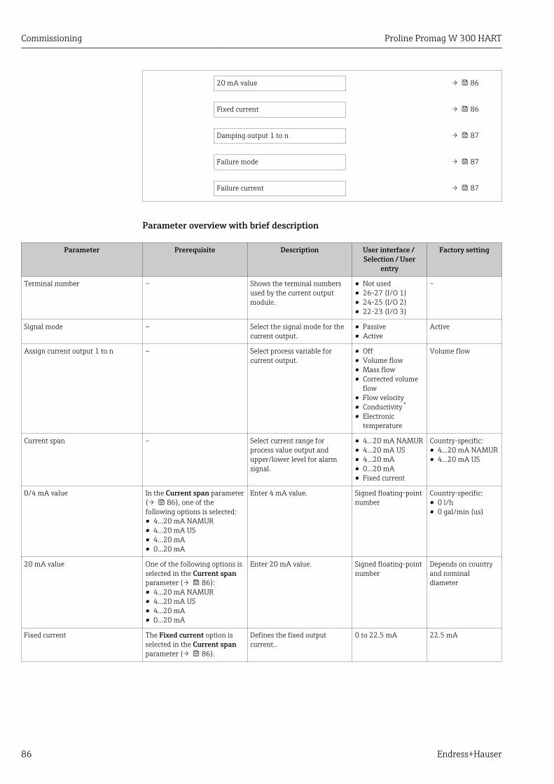
Commissioning Proline Promag W 300 HART
86 Endress+Hauser
20 mA value → 86
Fixed current → 86
Damping output 1 to n → 87
Failure mode → 87
Failure current → 87
Parameter overview with brief description
Parameter Prerequisite Description User interface / Selection / User
entry
Factory setting
Terminal number – Shows the terminal numbersused by the current outputmodule.
• Not used• 26-27 (I/O 1)• 24-25 (I/O 2)• 22-23 (I/O 3)
–
Signal mode – Select the signal mode for thecurrent output.
• Passive• Active
Active
Assign current output 1 to n – Select process variable forcurrent output.
• Off• Volume flow• Mass flow• Corrected volume
flow• Flow velocity• Conductivity *
• Electronictemperature
Volume flow
Current span – Select current range forprocess value output andupper/lower level for alarmsignal.
• 4...20 mA NAMUR• 4...20 mA US• 4...20 mA• 0...20 mA• Fixed current
Country-specific:• 4...20 mA NAMUR• 4...20 mA US
0/4 mA value In the Current span parameter(→ 86), one of thefollowing options is selected:• 4...20 mA NAMUR• 4...20 mA US• 4...20 mA• 0...20 mA
Enter 4 mA value. Signed floating-pointnumber
Country-specific:• 0 l/h• 0 gal/min (us)
20 mA value One of the following options isselected in the Current spanparameter (→ 86):• 4...20 mA NAMUR• 4...20 mA US• 4...20 mA• 0...20 mA
Enter 20 mA value. Signed floating-pointnumber
Depends on countryand nominaldiameter
Fixed current The Fixed current option isselected in the Current spanparameter (→ 86).
Defines the fixed outputcurrent..
0 to 22.5 mA 22.5 mA
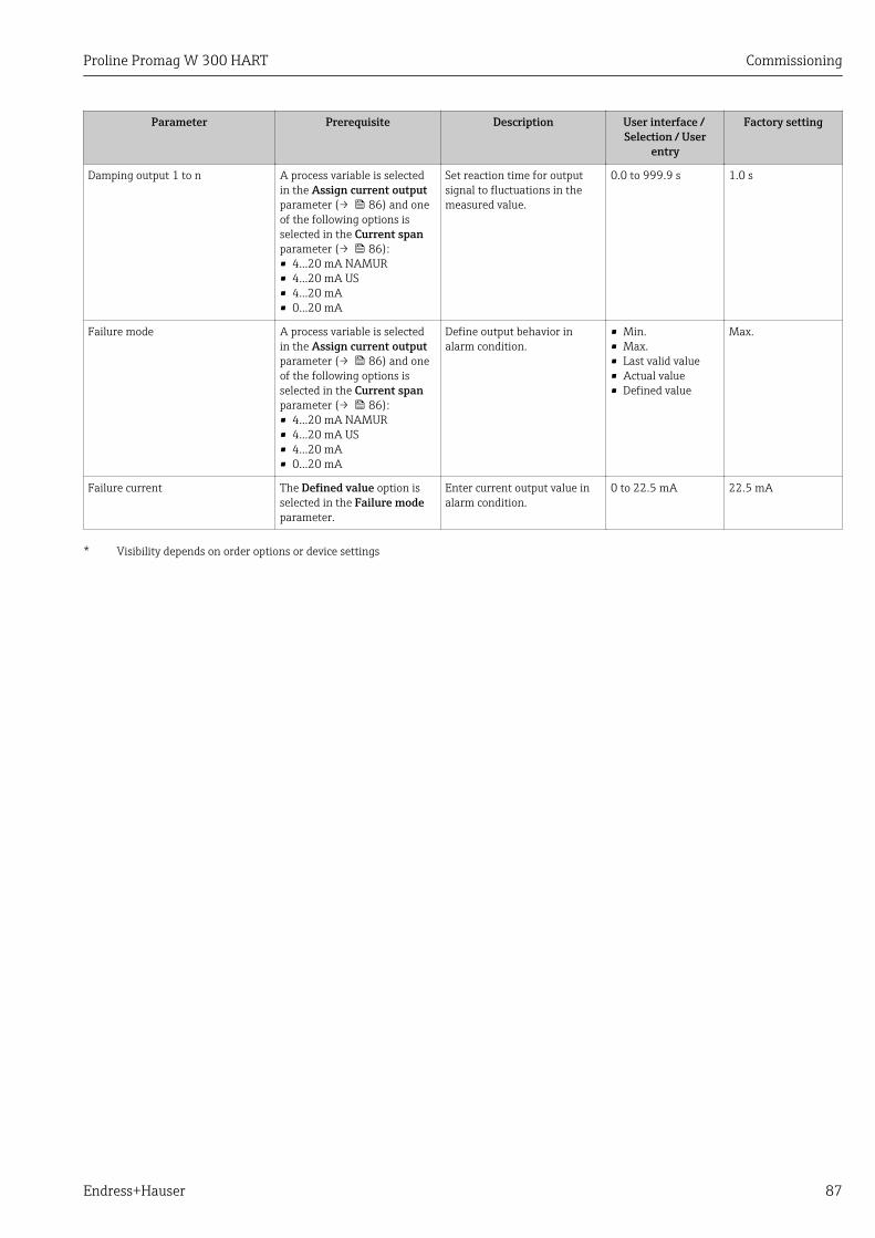
Proline Promag W 300 HART Commissioning
Endress+Hauser 87
Parameter Prerequisite Description User interface / Selection / User
entry
Factory setting
Damping output 1 to n A process variable is selectedin the Assign current outputparameter (→ 86) and oneof the following options isselected in the Current spanparameter (→ 86):• 4...20 mA NAMUR• 4...20 mA US• 4...20 mA• 0...20 mA
Set reaction time for outputsignal to fluctuations in themeasured value.
0.0 to 999.9 s 1.0 s
Failure mode A process variable is selectedin the Assign current outputparameter (→ 86) and oneof the following options isselected in the Current spanparameter (→ 86):• 4...20 mA NAMUR• 4...20 mA US• 4...20 mA• 0...20 mA
Define output behavior inalarm condition.
• Min.• Max.• Last valid value• Actual value• Defined value
Max.
Failure current The Defined value option isselected in the Failure modeparameter.
Enter current output value inalarm condition.
0 to 22.5 mA 22.5 mA
* Visibility depends on order options or device settings
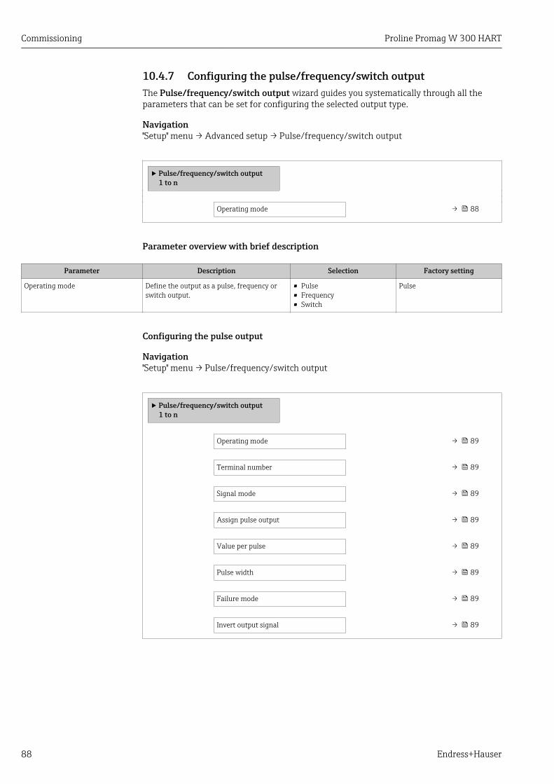
Commissioning Proline Promag W 300 HART
88 Endress+Hauser
10.4.7 Configuring the pulse/frequency/switch outputThe Pulse/frequency/switch output wizard guides you systematically through all theparameters that can be set for configuring the selected output type.
Navigation"Setup" menu → Advanced setup → Pulse/frequency/switch output
‣ Pulse/frequency/switch output1 to n
Operating mode → 88
Parameter overview with brief description
Parameter Description Selection Factory setting
Operating mode Define the output as a pulse, frequency orswitch output.
• Pulse• Frequency• Switch
Pulse
Configuring the pulse output
Navigation"Setup" menu → Pulse/frequency/switch output
‣ Pulse/frequency/switch output1 to n
Operating mode → 89
Terminal number → 89
Signal mode → 89
Assign pulse output → 89
Value per pulse → 89
Pulse width → 89
Failure mode → 89
Invert output signal → 89

Proline Promag W 300 HART Commissioning
Endress+Hauser 89
Parameter overview with brief description
Parameter Prerequisite Description Selection / Userinterface / User
entry
Factory setting
Operating mode – Define the output as a pulse,frequency or switch output.
• Pulse• Frequency• Switch
Pulse
Terminal number – Shows the terminal numbersused by the PFS outputmodule.
• Not used• 24-25 (I/O 2)• 22-23 (I/O 3)
–
Signal mode – Select the signal mode for thePFS output.
• Passive• Active
Passive
Assign pulse output 1 to n The Pulse option is selected inthe Operating modeparameter parameter.
Select process variable forpulse output.
• Off• Volume flow• Mass flow• Corrected volume
flow
Off
Value per pulse The Pulse option is selected inthe Operating modeparameter (→ 88) and aprocess variable is selected inthe Assign pulse outputparameter (→ 89).
Enter measured value at whicha pulse is output.
Signed floating-pointnumber
Depends on countryand nominaldiameter
Pulse width The Pulse option is selected inthe Operating modeparameter (→ 88) and aprocess variable is selected inthe Assign pulse outputparameter (→ 89).
Define time width of theoutput pulse.
0.05 to 2 000 ms 100 ms
Failure mode The Pulse option is selected inthe Operating modeparameter (→ 88) and aprocess variable is selected inthe Assign pulse outputparameter (→ 89).
Define output behavior inalarm condition.
• Actual value• No pulses
No pulses
Invert output signal – Invert the output signal. • No• Yes
No
Configuring the frequency output
Navigation"Setup" menu → Pulse/frequency/switch output
‣ Pulse/frequency/switch output1 to n
Operating mode → 90
Terminal number → 90
Signal mode → 90
Assign frequency output → 90
Minimum frequency value → 90
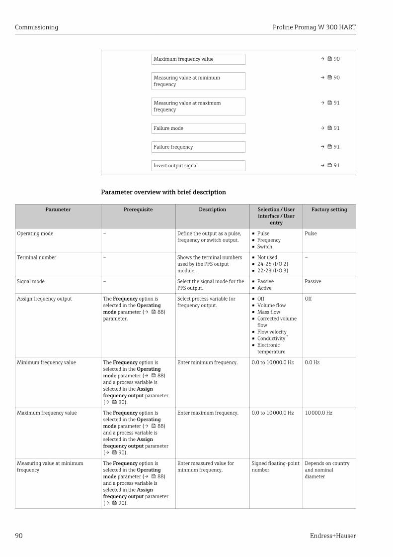
Commissioning Proline Promag W 300 HART
90 Endress+Hauser
Maximum frequency value → 90
Measuring value at minimumfrequency
→ 90
Measuring value at maximumfrequency
→ 91
Failure mode → 91
Failure frequency → 91
Invert output signal → 91
Parameter overview with brief description
Parameter Prerequisite Description Selection / Userinterface / User
entry
Factory setting
Operating mode – Define the output as a pulse,frequency or switch output.
• Pulse• Frequency• Switch
Pulse
Terminal number – Shows the terminal numbersused by the PFS outputmodule.
• Not used• 24-25 (I/O 2)• 22-23 (I/O 3)
–
Signal mode – Select the signal mode for thePFS output.
• Passive• Active
Passive
Assign frequency output The Frequency option isselected in the Operatingmode parameter (→ 88)parameter.
Select process variable forfrequency output.
• Off• Volume flow• Mass flow• Corrected volume
flow• Flow velocity• Conductivity *
• Electronictemperature
Off
Minimum frequency value The Frequency option isselected in the Operatingmode parameter (→ 88)and a process variable isselected in the Assignfrequency output parameter(→ 90).
Enter minimum frequency. 0.0 to 10 000.0 Hz 0.0 Hz
Maximum frequency value The Frequency option isselected in the Operatingmode parameter (→ 88)and a process variable isselected in the Assignfrequency output parameter(→ 90).
Enter maximum frequency. 0.0 to 10 000.0 Hz 10 000.0 Hz
Measuring value at minimumfrequency
The Frequency option isselected in the Operatingmode parameter (→ 88)and a process variable isselected in the Assignfrequency output parameter(→ 90).
Enter measured value forminmum frequency.
Signed floating-pointnumber
Depends on countryand nominaldiameter

Proline Promag W 300 HART Commissioning
Endress+Hauser 91
Parameter Prerequisite Description Selection / Userinterface / User
entry
Factory setting
Measuring value at maximumfrequency
The Frequency option isselected in the Operatingmode parameter (→ 88)and a process variable isselected in the Assignfrequency output parameter(→ 90).
Enter measured value formaximum frequency.
Signed floating-pointnumber
Depends on countryand nominaldiameter
Failure mode The Frequency option isselected in the Operatingmode parameter (→ 88)and a process variable isselected in the Assignfrequency output parameter(→ 90).
Define output behavior inalarm condition.
• Actual value• Defined value• 0 Hz
0 Hz
Failure frequency The Frequency option isselected in the Operatingmode parameter (→ 88)and a process variable isselected in the Assignfrequency output parameter(→ 90).
Enter frequency output valuein alarm condition.
0.0 to 12 500.0 Hz 0.0 Hz
Invert output signal – Invert the output signal. • No• Yes
No
* Visibility depends on order options or device settings
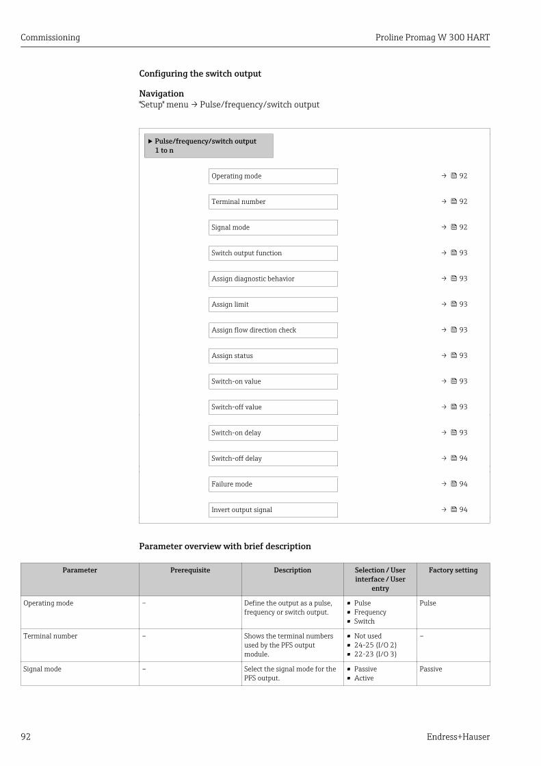
Commissioning Proline Promag W 300 HART
92 Endress+Hauser
Configuring the switch output
Navigation"Setup" menu → Pulse/frequency/switch output
‣ Pulse/frequency/switch output1 to n
Operating mode → 92
Terminal number → 92
Signal mode → 92
Switch output function → 93
Assign diagnostic behavior → 93
Assign limit → 93
Assign flow direction check → 93
Assign status → 93
Switch-on value → 93
Switch-off value → 93
Switch-on delay → 93
Switch-off delay → 94
Failure mode → 94
Invert output signal → 94
Parameter overview with brief description
Parameter Prerequisite Description Selection / Userinterface / User
entry
Factory setting
Operating mode – Define the output as a pulse,frequency or switch output.
• Pulse• Frequency• Switch
Pulse
Terminal number – Shows the terminal numbersused by the PFS outputmodule.
• Not used• 24-25 (I/O 2)• 22-23 (I/O 3)
–
Signal mode – Select the signal mode for thePFS output.
• Passive• Active
Passive

Proline Promag W 300 HART Commissioning
Endress+Hauser 93
Parameter Prerequisite Description Selection / Userinterface / User
entry
Factory setting
Switch output function The Switch option is selectedin the Operating modeparameter.
Select function for switchoutput.
• Off• On• Diagnostic
behavior• Limit• Flow direction
check• Status
Off
Assign diagnostic behavior • In the Operating modeparameter, the Switchoption is selected.
• In the Switch outputfunction parameter, theDiagnostic behavior optionis selected.
Select diagnostic behavior forswitch output.
• Alarm• Alarm or warning• Warning
Alarm
Assign limit • The Switch option isselected in the Operatingmode parameter parameter.
• The Limit option is selectedin the Switch outputfunction parameterparameter.
Select process variable for limitfunction.
• Off• Volume flow• Mass flow• Corrected volume
flow• Flow velocity• Conductivity *
• Totalizer 1• Totalizer 2• Totalizer 3• Electronic
temperature
Volume flow
Assign flow direction check • The Switch option isselected in the Operatingmode parameter.
• The Flow direction checkoption is selected in theSwitch output functionparameter.
Select process variable for flowdirection monitoring.
• Off• Volume flow• Mass flow• Corrected volume
flow
Volume flow
Assign status • The Switch option isselected in the Operatingmode parameter.
• The Status option isselected in the Switchoutput function parameter.
Select device status for switchoutput.
• Empty pipedetection
• Low flow cut off
Empty pipe detection
Switch-on value • In the Operating modeparameter, the Switchoption is selected.
• In the Switch outputfunction parameter, theLimit option is selected.
Enter measured value for theswitch-on point.
Signed floating-pointnumber
Country-specific:• 0 l/h• 0 gal/min (us)
Switch-off value • In the Operating modeparameter, the Switchoption is selected.
• In the Switch outputfunction parameter, theLimit option is selected.
Enter measured value for theswitch-off point.
Signed floating-pointnumber
Country-specific:• 0 l/h• 0 gal/min (us)
Switch-on delay • The Switch option isselected in the Operatingmode parameter.
• The Limit option is selectedin the Switch outputfunction parameter.
Define delay for the switch-onof status output.
0.0 to 100.0 s 0.0 s
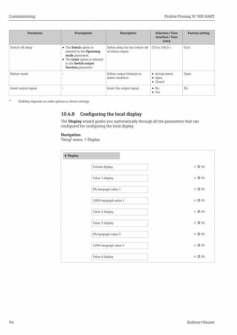
Commissioning Proline Promag W 300 HART
94 Endress+Hauser
Parameter Prerequisite Description Selection / Userinterface / User
entry
Factory setting
Switch-off delay • The Switch option isselected in the Operatingmode parameter.
• The Limit option is selectedin the Switch outputfunction parameter.
Define delay for the switch-offof status output.
0.0 to 100.0 s 0.0 s
Failure mode – Define output behavior inalarm condition.
• Actual status• Open• Closed
Open
Invert output signal – Invert the output signal. • No• Yes
No
* Visibility depends on order options or device settings
10.4.8 Configuring the local displayThe Display wizard guides you systematically through all the parameters that canconfigured for configuring the local display.
Navigation"Setup" menu → Display
‣ Display
Format display → 95
Value 1 display → 95
0% bargraph value 1 → 95
100% bargraph value 1 → 95
Value 2 display → 95
Value 3 display → 95
0% bargraph value 3 → 95
100% bargraph value 3 → 95
Value 4 display → 95
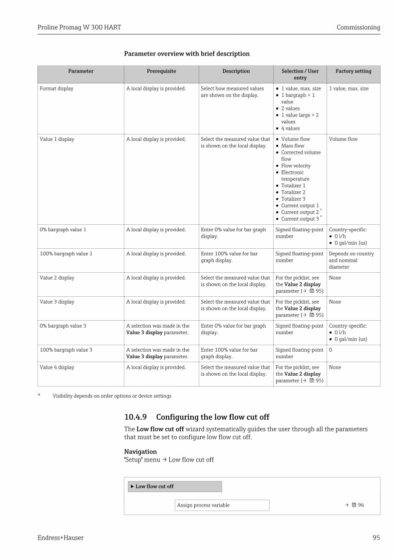
Proline Promag W 300 HART Commissioning
Endress+Hauser 95
Parameter overview with brief description
Parameter Prerequisite Description Selection / Userentry
Factory setting
Format display A local display is provided. Select how measured valuesare shown on the display.
• 1 value, max. size• 1 bargraph + 1
value• 2 values• 1 value large + 2
values• 4 values
1 value, max. size
Value 1 display A local display is provided. Select the measured value thatis shown on the local display.
• Volume flow• Mass flow• Corrected volume
flow• Flow velocity• Electronic
temperature• Totalizer 1• Totalizer 2• Totalizer 3• Current output 1• Current output 2 *
• Current output 3 *
Volume flow
0% bargraph value 1 A local display is provided. Enter 0% value for bar graphdisplay.
Signed floating-pointnumber
Country-specific:• 0 l/h• 0 gal/min (us)
100% bargraph value 1 A local display is provided. Enter 100% value for bargraph display.
Signed floating-pointnumber
Depends on countryand nominaldiameter
Value 2 display A local display is provided. Select the measured value thatis shown on the local display.
For the picklist, seethe Value 2 displayparameter (→ 95)
None
Value 3 display A local display is provided. Select the measured value thatis shown on the local display.
For the picklist, seethe Value 2 displayparameter (→ 95)
None
0% bargraph value 3 A selection was made in theValue 3 display parameter.
Enter 0% value for bar graphdisplay.
Signed floating-pointnumber
Country-specific:• 0 l/h• 0 gal/min (us)
100% bargraph value 3 A selection was made in theValue 3 display parameter.
Enter 100% value for bargraph display.
Signed floating-pointnumber
0
Value 4 display A local display is provided. Select the measured value thatis shown on the local display.
For the picklist, seethe Value 2 displayparameter (→ 95)
None
* Visibility depends on order options or device settings
10.4.9 Configuring the low flow cut offThe Low flow cut off wizard systematically guides the user through all the parametersthat must be set to configure low flow cut off.
Navigation"Setup" menu → Low flow cut off
‣ Low flow cut off
Assign process variable → 96
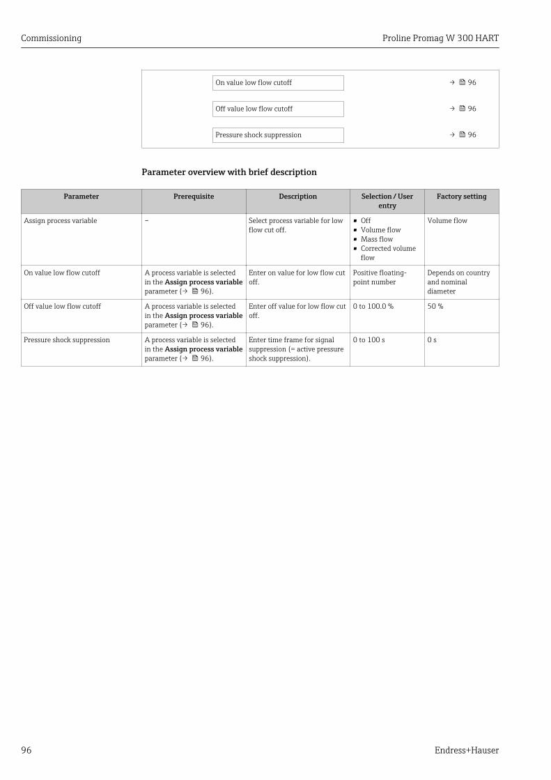
Commissioning Proline Promag W 300 HART
96 Endress+Hauser
On value low flow cutoff → 96
Off value low flow cutoff → 96
Pressure shock suppression → 96
Parameter overview with brief description
Parameter Prerequisite Description Selection / Userentry
Factory setting
Assign process variable – Select process variable for lowflow cut off.
• Off• Volume flow• Mass flow• Corrected volume
flow
Volume flow
On value low flow cutoff A process variable is selectedin the Assign process variableparameter (→ 96).
Enter on value for low flow cutoff.
Positive floating-point number
Depends on countryand nominaldiameter
Off value low flow cutoff A process variable is selectedin the Assign process variableparameter (→ 96).
Enter off value for low flow cutoff.
0 to 100.0 % 50 %
Pressure shock suppression A process variable is selectedin the Assign process variableparameter (→ 96).
Enter time frame for signalsuppression (= active pressureshock suppression).
0 to 100 s 0 s
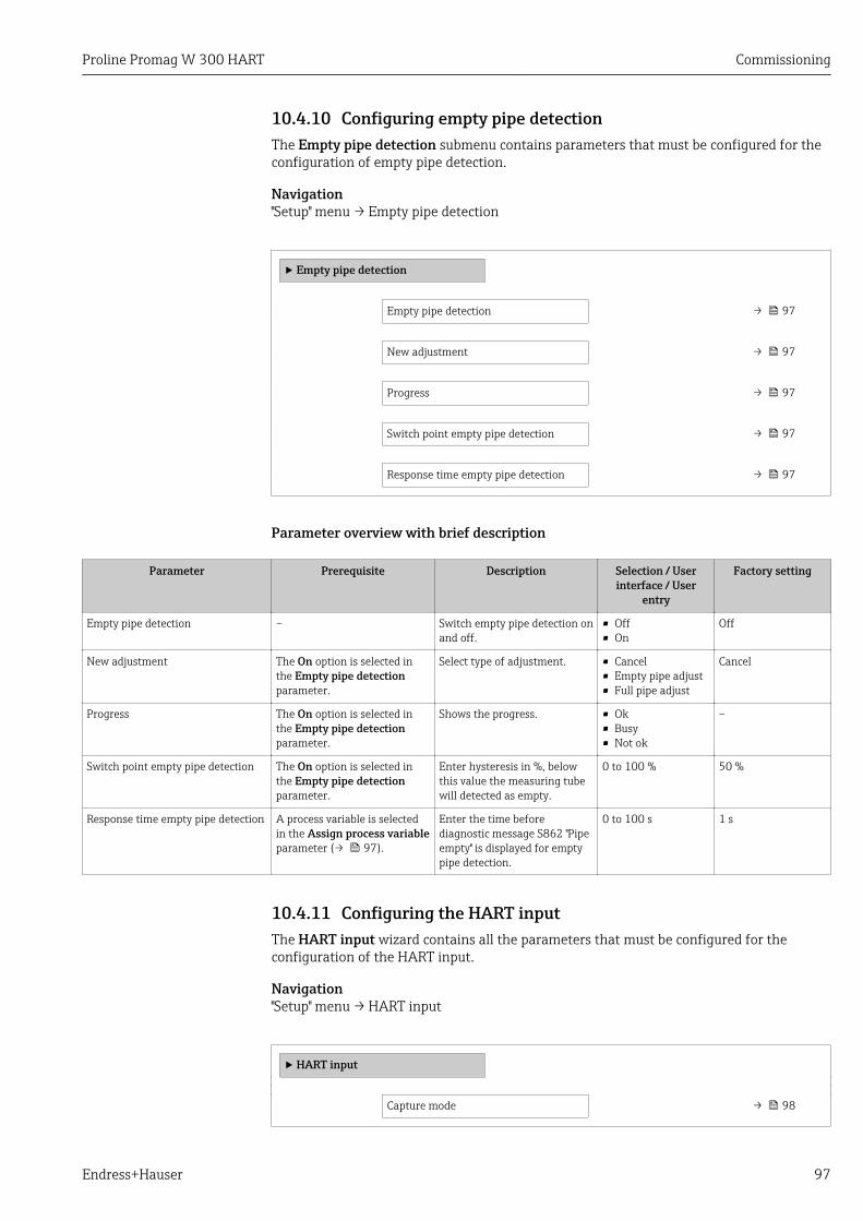
Proline Promag W 300 HART Commissioning
Endress+Hauser 97
10.4.10 Configuring empty pipe detectionThe Empty pipe detection submenu contains parameters that must be configured for theconfiguration of empty pipe detection.
Navigation"Setup" menu → Empty pipe detection
‣ Empty pipe detection
Empty pipe detection → 97
New adjustment → 97
Progress → 97
Switch point empty pipe detection → 97
Response time empty pipe detection → 97
Parameter overview with brief description
Parameter Prerequisite Description Selection / Userinterface / User
entry
Factory setting
Empty pipe detection – Switch empty pipe detection onand off.
• Off• On
Off
New adjustment The On option is selected inthe Empty pipe detectionparameter.
Select type of adjustment. • Cancel• Empty pipe adjust• Full pipe adjust
Cancel
Progress The On option is selected inthe Empty pipe detectionparameter.
Shows the progress. • Ok• Busy• Not ok
–
Switch point empty pipe detection The On option is selected inthe Empty pipe detectionparameter.
Enter hysteresis in %, belowthis value the measuring tubewill detected as empty.
0 to 100 % 50 %
Response time empty pipe detection A process variable is selectedin the Assign process variableparameter (→ 97).
Enter the time beforediagnostic message S862 ''Pipeempty'' is displayed for emptypipe detection.
0 to 100 s 1 s
10.4.11 Configuring the HART inputThe HART input wizard contains all the parameters that must be configured for theconfiguration of the HART input.
Navigation"Setup" menu → HART input
‣ HART input
Capture mode → 98

Commissioning Proline Promag W 300 HART
98 Endress+Hauser
Device ID → 98
Device type → 98
Manufacturer ID → 98
Burst command → 98
Slot number → 98
Timeout → 99
Failure mode → 99
Failure value → 99
"Configuration" submenu
Navigation"Expert" menu → Communication → HART input → Configuration
Parameter overview with brief description
Parameter Prerequisite Description Selection / Userentry
Factory setting
Capture mode – Select capture mode via burstor master communication.
• Off• Burst network• Master network
Off
Device ID The Master network option isselected in the Capture modeparameter.
Enter device ID of externaldevice.
6-digit value:• Via local
operation: enter ashexadecimal ordecimal number
• Via operating tool:enter as decimalnumber
0
Device type In the Capture modeparameter, the Masternetwork option is selected.
Enter device type of externaldevice.
2-digit hexadecimalnumber
0x00
Manufacturer ID The Master network option isselected in the Capture modeparameter.
Enter manufacture ID ofexternal device.
2-digit value:• Via local
operation: enter ashexadecimal ordecimal number
• Via operating tool:enter as decimalnumber
0
Burst command The Burst network option orthe Master network optionare selected in the Capturemode parameter.
Select command to read inexternal process variable.
• Command 1• Command 3• Command 9• Command 33
Command 1
Slot number The Burst network option orthe Master network option isselected in the Capture modeparameter.
Define position of externalprocess variable in burstcommand.
1 to 8 1

Proline Promag W 300 HART Commissioning
Endress+Hauser 99
Parameter Prerequisite Description Selection / Userentry
Factory setting
Timeout The Burst network option orthe Master network option isselected in the Capture modeparameter.
Enter deadline for processvariable of external device.
If the waiting time isexceeded, the diagnosticmessage F410 Datatransfer is displayed.
1 to 120 s 5 s
Failure mode In the Capture modeparameter, the Burst networkoption or Master networkoption is selected.
Define behavior if externalprocess variable is missed.
• Alarm• Last valid value• Defined value
Alarm
Failure value The following conditions aremet:• In the Capture mode
parameter, the Burstnetwork option or Masternetwork option is selected.
• In the Failure modeparameter, the Definedvalue option is selected.
Enter value to be used by thedevice if input value fromexternal device is missing.
Signed floating-pointnumber
0
"Input" submenu
Navigation"Expert" menu → Communication → HART input → Input
Parameter overview with brief description
Parameter Description User interface
Value Signed floating-point number
Status • Manual/Fixed• Good• Poor accuracy• Bad
10.4.12 Configuring the relay outputThe Relay output wizard guides the user systematically through all the parameters thathave to be set for configuring the relay output.
Navigation"Setup" menu → Relay output 1 to n
‣ RelaisOutput 1 to n
Switch output function → 100
Assign flow direction check → 100
Assign limit → 100
Assign diagnostic behavior → 100
Assign status → 100

Commissioning Proline Promag W 300 HART
100 Endress+Hauser
Switch-off value → 100
Switch-on value → 100
Failure mode → 101
Parameter overview with brief description
Parameter Prerequisite Description Selection / Userinterface / User
entry
Factory setting
Relay output function – Select the function for therelay output.
• Closed• Open• Diagnostic
behavior• Limit• Flow direction
check• Digital Output
Closed
Terminal number – Shows the terminal numbersused by the relay outputmodule.
• Not used• 24-25 (I/O 2)• 22-23 (I/O 3)
–
Assign flow direction check In the Relay output functionparameter, the Flow directioncheck option is selected.
Select process variable for flowdirection monitoring.
• Off• Volume flow• Mass flow• Corrected volume
flow
Volume flow
Assign limit The Limit option is selected inthe Relay output functionparameter parameter.
Select process variable for limitfunction.
• Off• Volume flow• Mass flow• Corrected volume
flow• Flow velocity• Conductivity *
• Totalizer 1• Totalizer 2• Totalizer 3• Electronic
temperature
Volume flow
Assign diagnostic behavior In the Relay output functionparameter, the Diagnosticbehavior option is selected.
Select diagnostic behavior forswitch output.
• Alarm• Alarm or warning• Warning
Alarm
Assign status In the Relay output functionparameter, the Digital Outputoption is selected.
Select device status for switchoutput.
• Partially filled pipedetection
• Low flow cut off
Partially filled pipedetection
Switch-off value In the Relay output functionparameter, the Limit option isselected.
Enter measured value for theswitch-off point.
Signed floating-pointnumber
Country-specific:• 0 l/h• 0 gal(us)/min
Switch-off delay In the Relay output functionparameter, the Limit option isselected.
Define delay for the switch-offof status output.
0.0 to 100.0 s 0.0 s
Switch-on value In the Relay output functionparameter, the Limit option isselected.
Enter measured value for theswitch-on point.
Signed floating-pointnumber
Country-specific:• 0 l/h• 0 gal(us)/min
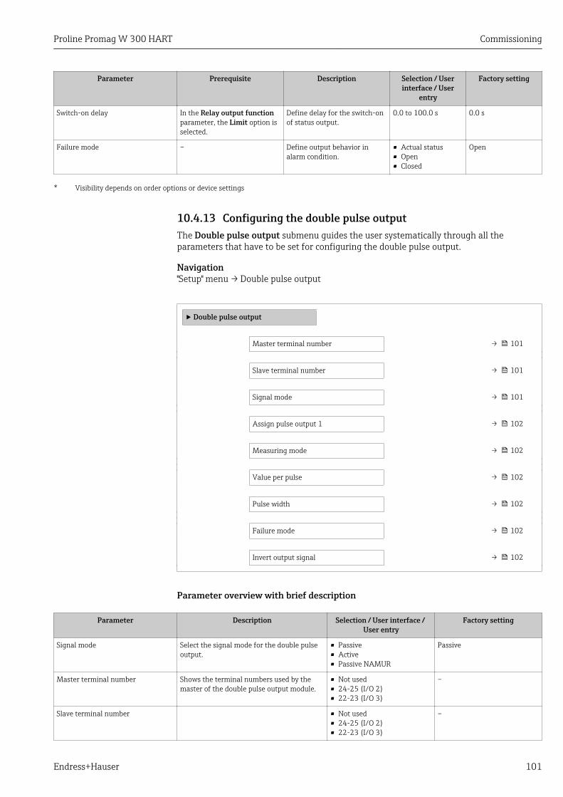
Proline Promag W 300 HART Commissioning
Endress+Hauser 101
Parameter Prerequisite Description Selection / Userinterface / User
entry
Factory setting
Switch-on delay In the Relay output functionparameter, the Limit option isselected.
Define delay for the switch-onof status output.
0.0 to 100.0 s 0.0 s
Failure mode – Define output behavior inalarm condition.
• Actual status• Open• Closed
Open
* Visibility depends on order options or device settings
10.4.13 Configuring the double pulse outputThe Double pulse output submenu guides the user systematically through all theparameters that have to be set for configuring the double pulse output.
Navigation"Setup" menu → Double pulse output
‣ Double pulse output
Master terminal number → 101
Slave terminal number → 101
Signal mode → 101
Assign pulse output 1 → 102
Measuring mode → 102
Value per pulse → 102
Pulse width → 102
Failure mode → 102
Invert output signal → 102
Parameter overview with brief description
Parameter Description Selection / User interface / User entry
Factory setting
Signal mode Select the signal mode for the double pulseoutput.
• Passive• Active• Passive NAMUR
Passive
Master terminal number Shows the terminal numbers used by themaster of the double pulse output module.
• Not used• 24-25 (I/O 2)• 22-23 (I/O 3)
–
Slave terminal number • Not used• 24-25 (I/O 2)• 22-23 (I/O 3)
–
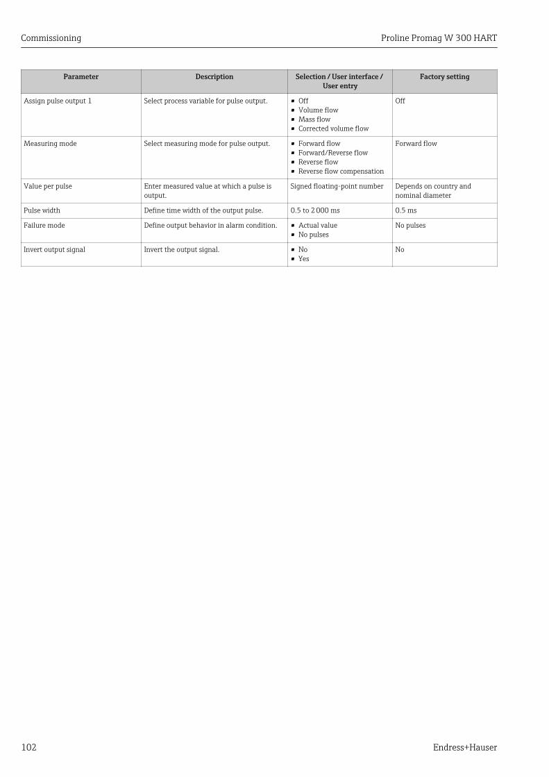
Commissioning Proline Promag W 300 HART
102 Endress+Hauser
Parameter Description Selection / User interface / User entry
Factory setting
Assign pulse output 1 Select process variable for pulse output. • Off• Volume flow• Mass flow• Corrected volume flow
Off
Measuring mode Select measuring mode for pulse output. • Forward flow• Forward/Reverse flow• Reverse flow• Reverse flow compensation
Forward flow
Value per pulse Enter measured value at which a pulse isoutput.
Signed floating-point number Depends on country andnominal diameter
Pulse width Define time width of the output pulse. 0.5 to 2 000 ms 0.5 ms
Failure mode Define output behavior in alarm condition. • Actual value• No pulses
No pulses
Invert output signal Invert the output signal. • No• Yes
No
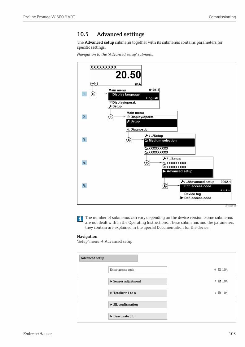
Proline Promag W 300 HART Commissioning
Endress+Hauser 103
10.5 Advanced settingsThe Advanced setup submenu together with its submenus contains parameters forspecific settings.
Navigation to the "Advanced setup" submenu
X X X X X X XX X
20.50
0104-1
0092-1
****
XXXXXXXXX
XXXXXXXXX
XXXXXXXXX
XXXXXXXXX
mA
1.
2.
3.
4.
5.
Display/operat.
Setup
Diagnostic
Display/operat.
Setup
Main menu
English
Main menu
Medium selection
/ ../Setup
/ ../Setup
Advanced setup
Ent. access code
/ ../Advanced setup
Def. access code
Device tag
Display language
A0032223-EN
The number of submenus can vary depending on the device version. Some submenusare not dealt with in the Operating Instructions. These submenus and the parametersthey contain are explained in the Special Documentation for the device.
Navigation"Setup" menu → Advanced setup
Advanced setup
Enter access code → 104
‣ Sensor adjustment → 104
‣ Totalizer 1 to n → 104
‣ SIL confirmation
‣ Deactivate SIL

Commissioning Proline Promag W 300 HART
104 Endress+Hauser
‣ Display → 106
‣ Electrode cleaning circuit → 109
‣ WLAN settings → 109
‣ Heartbeat setup
‣ Configuration backup → 111
‣ Administration → 112
10.5.1 Using the parameter to enter the access code
Navigation"Setup" menu → Advanced setup
Parameter overview with brief description
Parameter Description User entry
Enter access code Enter access code to disable write protection of parameters. Max. 16-digit character string comprisingnumbers, letters and special characters
10.5.2 Carrying out a sensor adjustmentThe Sensor adjustment submenu contains parameters that pertain to the functionality ofthe sensor.
Navigation"Setup" menu → Advanced setup → Sensor adjustment
‣ Sensor adjustment
Installation direction → 104
Parameter overview with brief description
Parameter Description Selection Factory setting
Installation direction Set sign of flow direction to match thedirection of the arrow on the sensor.
• Flow in arrow direction• Flow against arrow direction
Flow in arrow direction
10.5.3 Configuring the totalizerIn the "Totalizer 1 to n" submenu the individual totalizer can be configured.
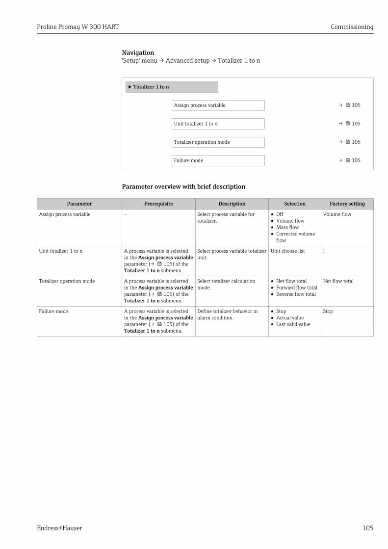
Proline Promag W 300 HART Commissioning
Endress+Hauser 105
Navigation"Setup" menu → Advanced setup → Totalizer 1 to n
‣ Totalizer 1 to n
Assign process variable → 105
Unit totalizer 1 to n → 105
Totalizer operation mode → 105
Failure mode → 105
Parameter overview with brief description
Parameter Prerequisite Description Selection Factory setting
Assign process variable – Select process variable fortotalizer.
• Off• Volume flow• Mass flow• Corrected volume
flow
Volume flow
Unit totalizer 1 to n A process variable is selectedin the Assign process variableparameter (→ 105) of theTotalizer 1 to n submenu.
Select process variable totalizerunit.
Unit choose list l
Totalizer operation mode A process variable is selectedin the Assign process variableparameter (→ 105) of theTotalizer 1 to n submenu.
Select totalizer calculationmode.
• Net flow total• Forward flow total• Reverse flow total
Net flow total
Failure mode A process variable is selectedin the Assign process variableparameter (→ 105) of theTotalizer 1 to n submenu.
Define totalizer behavior inalarm condition.
• Stop• Actual value• Last valid value
Stop

Commissioning Proline Promag W 300 HART
106 Endress+Hauser
10.5.4 Carrying out additional display configurationsIn the Display submenu you can set all the parameters associated with the configurationof the local display.
Navigation"Setup" menu → Advanced setup → Display
‣ Display
Format display → 107
Value 1 display → 107
0% bargraph value 1 → 107
100% bargraph value 1 → 107
Decimal places 1 → 107
Value 2 display → 107
Decimal places 2 → 107
Value 3 display → 107
0% bargraph value 3 → 107
100% bargraph value 3 → 107
Decimal places 3 → 107
Value 4 display → 107
Decimal places 4 → 108
Display language → 108
Display interval → 108
Display damping → 108
Header → 108
Header text → 108
Separator → 108
Backlight → 108
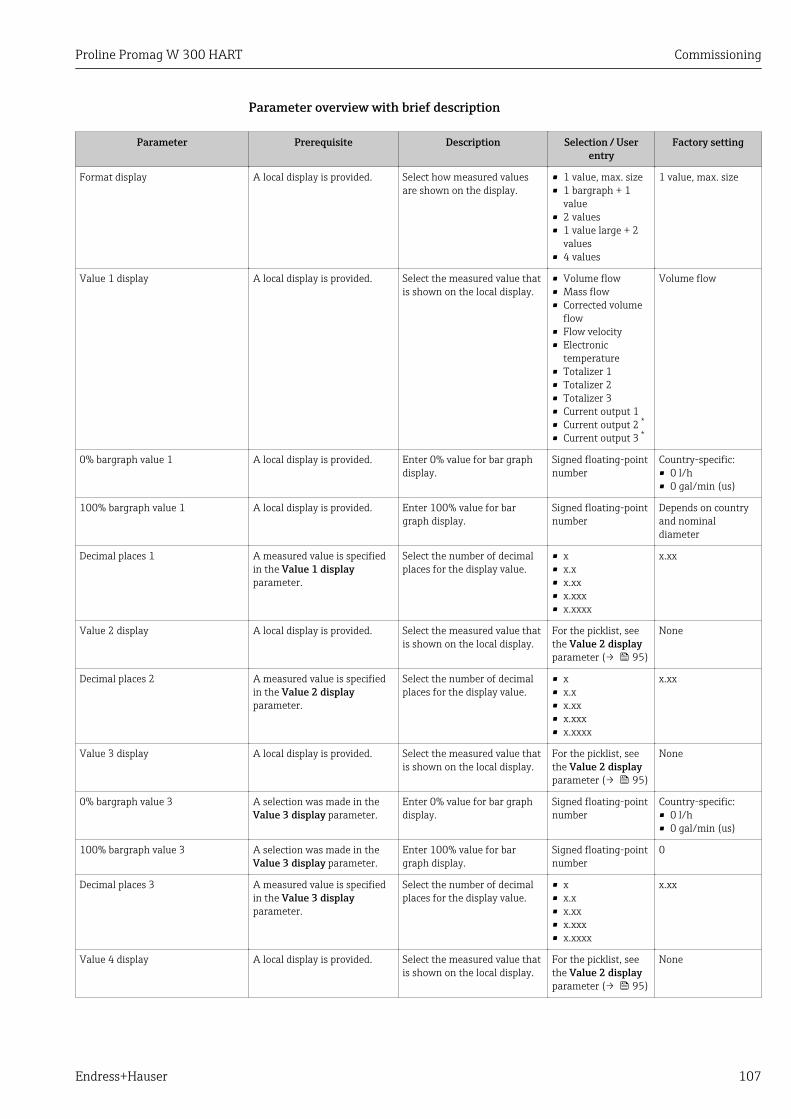
Proline Promag W 300 HART Commissioning
Endress+Hauser 107
Parameter overview with brief description
Parameter Prerequisite Description Selection / Userentry
Factory setting
Format display A local display is provided. Select how measured valuesare shown on the display.
• 1 value, max. size• 1 bargraph + 1
value• 2 values• 1 value large + 2
values• 4 values
1 value, max. size
Value 1 display A local display is provided. Select the measured value thatis shown on the local display.
• Volume flow• Mass flow• Corrected volume
flow• Flow velocity• Electronic
temperature• Totalizer 1• Totalizer 2• Totalizer 3• Current output 1• Current output 2 *
• Current output 3 *
Volume flow
0% bargraph value 1 A local display is provided. Enter 0% value for bar graphdisplay.
Signed floating-pointnumber
Country-specific:• 0 l/h• 0 gal/min (us)
100% bargraph value 1 A local display is provided. Enter 100% value for bargraph display.
Signed floating-pointnumber
Depends on countryand nominaldiameter
Decimal places 1 A measured value is specifiedin the Value 1 displayparameter.
Select the number of decimalplaces for the display value.
• x• x.x• x.xx• x.xxx• x.xxxx
x.xx
Value 2 display A local display is provided. Select the measured value thatis shown on the local display.
For the picklist, seethe Value 2 displayparameter (→ 95)
None
Decimal places 2 A measured value is specifiedin the Value 2 displayparameter.
Select the number of decimalplaces for the display value.
• x• x.x• x.xx• x.xxx• x.xxxx
x.xx
Value 3 display A local display is provided. Select the measured value thatis shown on the local display.
For the picklist, seethe Value 2 displayparameter (→ 95)
None
0% bargraph value 3 A selection was made in theValue 3 display parameter.
Enter 0% value for bar graphdisplay.
Signed floating-pointnumber
Country-specific:• 0 l/h• 0 gal/min (us)
100% bargraph value 3 A selection was made in theValue 3 display parameter.
Enter 100% value for bargraph display.
Signed floating-pointnumber
0
Decimal places 3 A measured value is specifiedin the Value 3 displayparameter.
Select the number of decimalplaces for the display value.
• x• x.x• x.xx• x.xxx• x.xxxx
x.xx
Value 4 display A local display is provided. Select the measured value thatis shown on the local display.
For the picklist, seethe Value 2 displayparameter (→ 95)
None
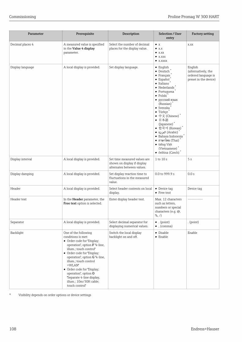
Commissioning Proline Promag W 300 HART
108 Endress+Hauser
Parameter Prerequisite Description Selection / Userentry
Factory setting
Decimal places 4 A measured value is specifiedin the Value 4 displayparameter.
Select the number of decimalplaces for the display value.
• x• x.x• x.xx• x.xxx• x.xxxx
x.xx
Display language A local display is provided. Set display language. • English• Deutsch *
• Français *
• Español *
• Italiano *
• Nederlands *
• Portuguesa *
• Polski *
• русский язык(Russian) *
• Svenska *
• Türkçe *
• 中文 (Chinese) *
• 日本語(Japanese) *
• 한국어 (Korean) *
• * (Arabic) العربية
• Bahasa Indonesia *
• ภาษาไทย (Thai) *
• tiếng Việt(Vietnamese) *
• čeština (Czech) *
English(alternatively, theordered language ispreset in the device)
Display interval A local display is provided. Set time measured values areshown on display if displayalternates between values.
1 to 10 s 5 s
Display damping A local display is provided. Set display reaction time tofluctuations in the measuredvalue.
0.0 to 999.9 s 0.0 s
Header A local display is provided. Select header contents on localdisplay.
• Device tag• Free text
Device tag
Header text In the Header parameter, theFree text option is selected.
Enter display header text. Max. 12 characterssuch as letters,numbers or specialcharacters (e.g. @,%, /)
------------
Separator A local display is provided. Select decimal separator fordisplaying numerical values.
• . (point)• , (comma)
. (point)
Backlight One of the followingconditions is met:• Order code for "Display;
operation", option F "4-line,illum.; touch control"
• Order code for "Display;operation", option G "4-line,illum.; touch control+WLAN"
• Order code for "Display;operation", option O"Separate 4-line display,illum.; 10m/30ft cable;touch control"
Switch the local displaybacklight on and off.
• Disable• Enable
Enable
* Visibility depends on order options or device settings
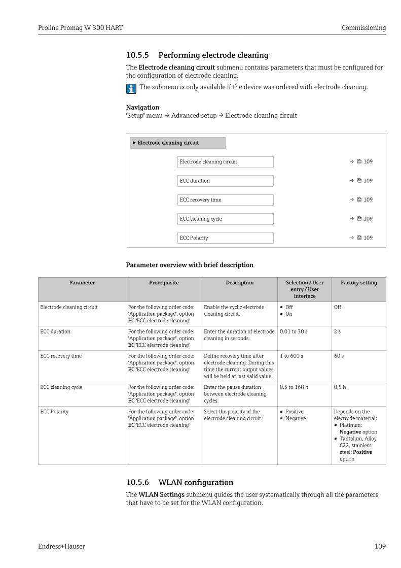
Proline Promag W 300 HART Commissioning
Endress+Hauser 109
10.5.5 Performing electrode cleaningThe Electrode cleaning circuit submenu contains parameters that must be configured forthe configuration of electrode cleaning.
The submenu is only available if the device was ordered with electrode cleaning.
Navigation"Setup" menu → Advanced setup → Electrode cleaning circuit
‣ Electrode cleaning circuit
Electrode cleaning circuit → 109
ECC duration → 109
ECC recovery time → 109
ECC cleaning cycle → 109
ECC Polarity → 109
Parameter overview with brief description
Parameter Prerequisite Description Selection / Userentry / User
interface
Factory setting
Electrode cleaning circuit For the following order code:"Application package", optionEC "ECC electrode cleaning"
Enable the cyclic electrodecleaning circuit.
• Off• On
Off
ECC duration For the following order code:"Application package", optionEC "ECC electrode cleaning"
Enter the duration of electrodecleaning in seconds.
0.01 to 30 s 2 s
ECC recovery time For the following order code:"Application package", optionEC "ECC electrode cleaning"
Define recovery time afterelectrode cleaning. During thistime the current output valueswill be held at last valid value.
1 to 600 s 60 s
ECC cleaning cycle For the following order code:"Application package", optionEC "ECC electrode cleaning"
Enter the pause durationbetween electrode cleaningcycles.
0.5 to 168 h 0.5 h
ECC Polarity For the following order code:"Application package", optionEC "ECC electrode cleaning"
Select the polarity of theelectrode cleaning circuit.
• Positive• Negative
Depends on theelectrode material:• Platinum:
Negative option• Tantalum, Alloy
C22, stainlesssteel: Positiveoption
10.5.6 WLAN configurationThe WLAN Settings submenu guides the user systematically through all the parametersthat have to be set for the WLAN configuration.
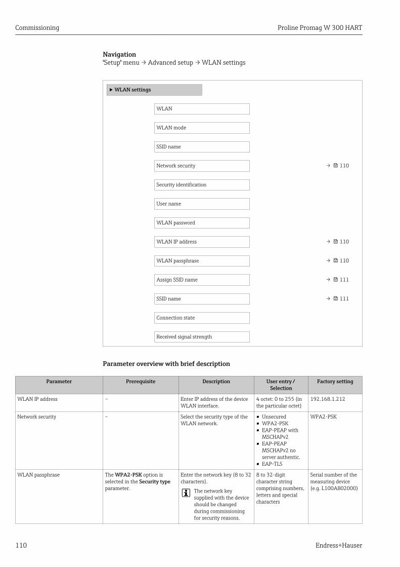
Commissioning Proline Promag W 300 HART
110 Endress+Hauser
Navigation"Setup" menu → Advanced setup → WLAN settings
‣ WLAN settings
WLAN
WLAN mode
SSID name
Network security → 110
Security identification
User name
WLAN password
WLAN IP address → 110
WLAN passphrase → 110
Assign SSID name → 111
SSID name → 111
Connection state
Received signal strength
Parameter overview with brief description
Parameter Prerequisite Description User entry / Selection
Factory setting
WLAN IP address – Enter IP address of the deviceWLAN interface.
4 octet: 0 to 255 (inthe particular octet)
192.168.1.212
Network security – Select the security type of theWLAN network.
• Unsecured• WPA2-PSK• EAP-PEAP with
MSCHAPv2• EAP-PEAP
MSCHAPv2 noserver authentic.
• EAP-TLS
WPA2-PSK
WLAN passphrase The WPA2-PSK option isselected in the Security typeparameter.
Enter the network key (8 to 32characters).
The network keysupplied with the deviceshould be changedduring commissioningfor security reasons.
8 to 32-digitcharacter stringcomprising numbers,letters and specialcharacters
Serial number of themeasuring device(e.g. L100A802000)
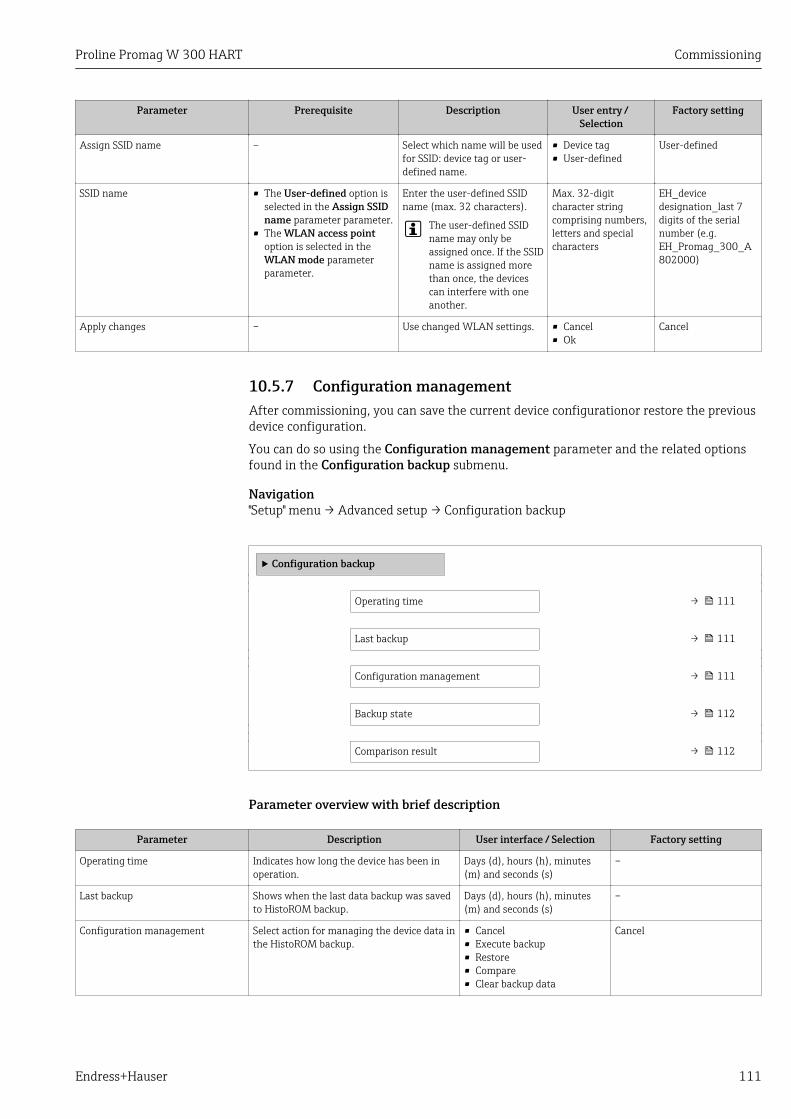
Proline Promag W 300 HART Commissioning
Endress+Hauser 111
Parameter Prerequisite Description User entry / Selection
Factory setting
Assign SSID name – Select which name will be usedfor SSID: device tag or user-defined name.
• Device tag• User-defined
User-defined
SSID name • The User-defined option isselected in the Assign SSIDname parameter parameter.
• The WLAN access pointoption is selected in theWLAN mode parameterparameter.
Enter the user-defined SSIDname (max. 32 characters).
The user-defined SSIDname may only beassigned once. If the SSIDname is assigned morethan once, the devicescan interfere with oneanother.
Max. 32-digitcharacter stringcomprising numbers,letters and specialcharacters
EH_devicedesignation_last 7digits of the serialnumber (e.g.EH_Promag_300_A802000)
Apply changes – Use changed WLAN settings. • Cancel• Ok
Cancel
10.5.7 Configuration managementAfter commissioning, you can save the current device configurationor restore the previousdevice configuration.
You can do so using the Configuration management parameter and the related optionsfound in the Configuration backup submenu.
Navigation"Setup" menu → Advanced setup → Configuration backup
‣ Configuration backup
Operating time → 111
Last backup → 111
Configuration management → 111
Backup state → 112
Comparison result → 112
Parameter overview with brief description
Parameter Description User interface / Selection Factory setting
Operating time Indicates how long the device has been inoperation.
Days (d), hours (h), minutes(m) and seconds (s)
–
Last backup Shows when the last data backup was savedto HistoROM backup.
Days (d), hours (h), minutes(m) and seconds (s)
–
Configuration management Select action for managing the device data inthe HistoROM backup.
• Cancel• Execute backup• Restore• Compare• Clear backup data
Cancel

Commissioning Proline Promag W 300 HART
112 Endress+Hauser
Parameter Description User interface / Selection Factory setting
Backup state Shows the current status of data saving orrestoring.
• None• Backup in progress• Restoring in progress• Delete in progress• Compare in progress• Restoring failed• Backup failed
None
Comparison result Comparison of current device data withHistoROM backup.
• Settings identical• Settings not identical• No backup available• Backup settings corrupt• Check not done• Dataset incompatible
Check not done
Function scope of the "Configuration management" parameter
Options Description
Cancel No action is executed and the user exits the parameter.
Execute backup A backup copy of the current device configuration is saved from the HistoROMbackup to the memory of the device. The backup copy includes the transmitter dataof the device.
Restore The last backup copy of the device configuration is restored from the devicememory to the device's HistoROM backup. The backup copy includes thetransmitter data of the device.
Compare The device configuration saved in the device memory is compared with the currentdevice configuration of the HistoROM backup.
Clear backup data The backup copy of the device configuration is deleted from the memory of thedevice.
HistoROM backupA HistoROM is a "non-volatile" device memory in the form of an EEPROM.
While this action is in progress, the configuration cannot be edited via the localdisplay and a message on the processing status appears on the display.
10.5.8 Using parameters for device administrationThe Administration submenu systematically guides the user through all the parametersthat can be used for device administration purposes.
Navigation"Setup" menu → Advanced setup → Administration
‣ Administration
‣ Define access code → 113
‣ Reset access code → 113
Device reset → 114
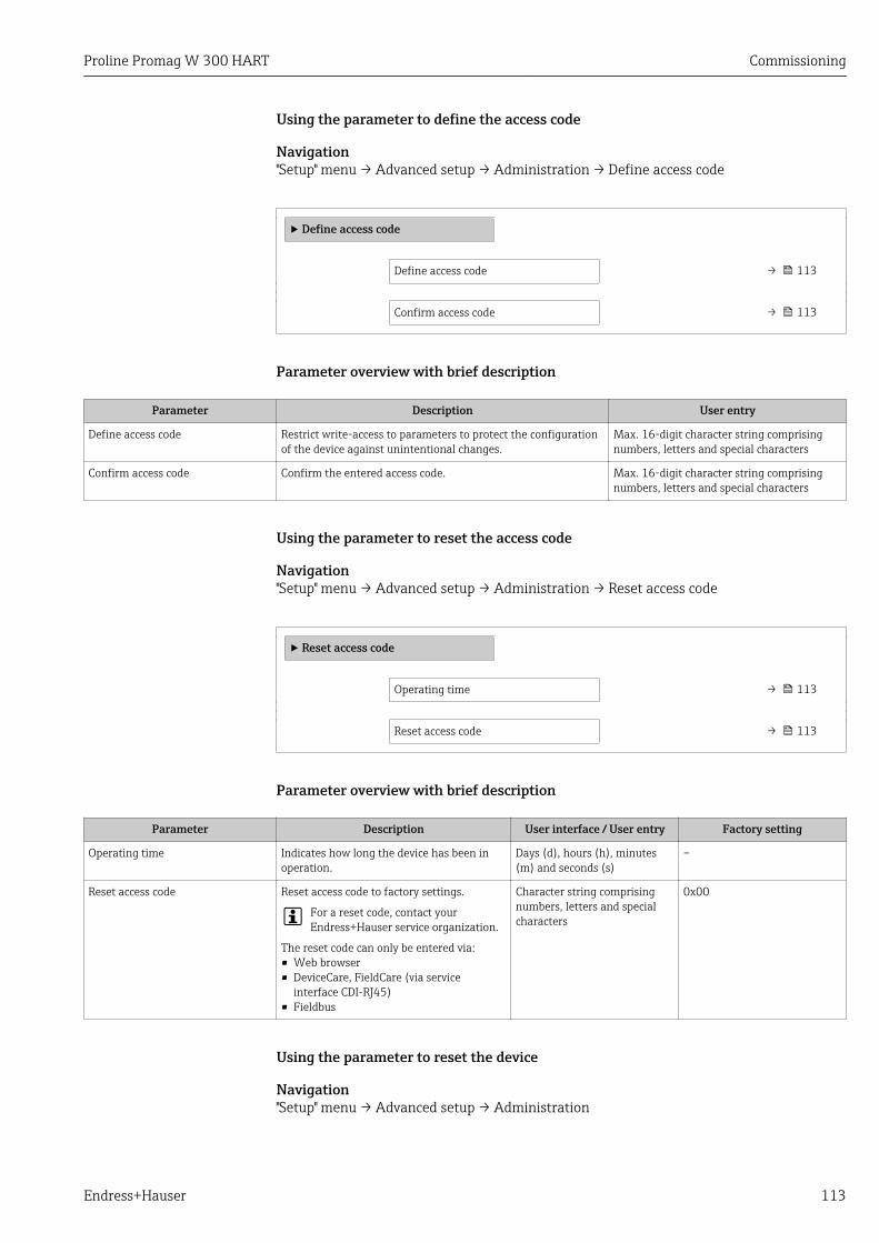
Proline Promag W 300 HART Commissioning
Endress+Hauser 113
Using the parameter to define the access code
Navigation"Setup" menu → Advanced setup → Administration → Define access code
‣ Define access code
Define access code → 113
Confirm access code → 113
Parameter overview with brief description
Parameter Description User entry
Define access code Restrict write-access to parameters to protect the configurationof the device against unintentional changes.
Max. 16-digit character string comprisingnumbers, letters and special characters
Confirm access code Confirm the entered access code. Max. 16-digit character string comprisingnumbers, letters and special characters
Using the parameter to reset the access code
Navigation"Setup" menu → Advanced setup → Administration → Reset access code
‣ Reset access code
Operating time → 113
Reset access code → 113
Parameter overview with brief description
Parameter Description User interface / User entry Factory setting
Operating time Indicates how long the device has been inoperation.
Days (d), hours (h), minutes(m) and seconds (s)
–
Reset access code Reset access code to factory settings.
For a reset code, contact yourEndress+Hauser service organization.
The reset code can only be entered via:• Web browser• DeviceCare, FieldCare (via service
interface CDI-RJ45)• Fieldbus
Character string comprisingnumbers, letters and specialcharacters
0x00
Using the parameter to reset the device
Navigation"Setup" menu → Advanced setup → Administration
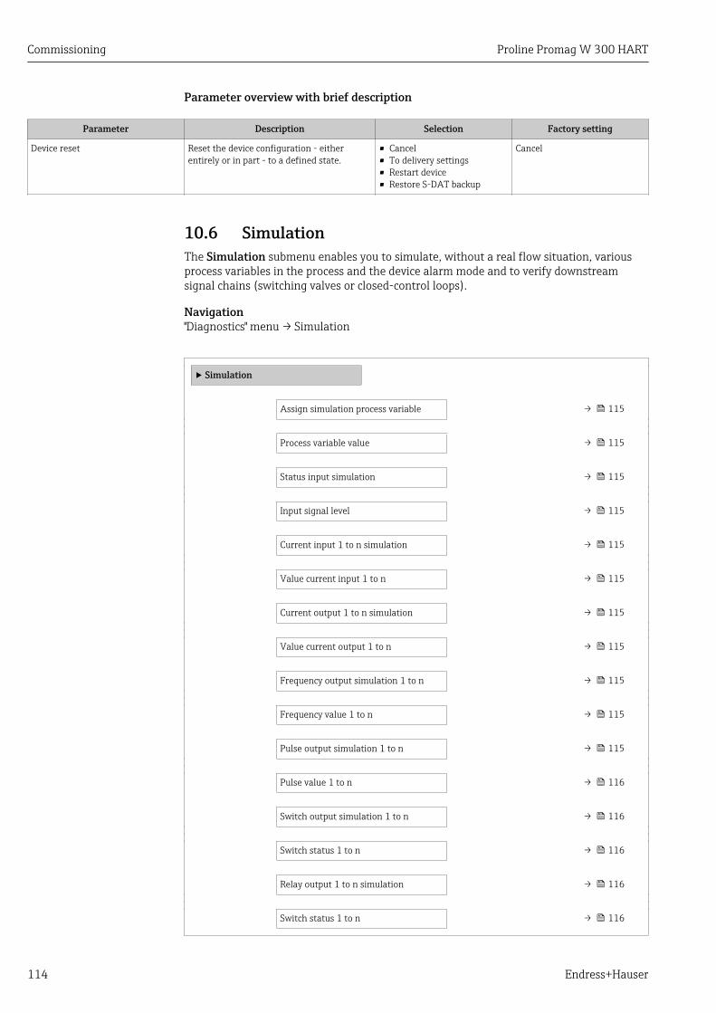
Commissioning Proline Promag W 300 HART
114 Endress+Hauser
Parameter overview with brief description
Parameter Description Selection Factory setting
Device reset Reset the device configuration - eitherentirely or in part - to a defined state.
• Cancel• To delivery settings• Restart device• Restore S-DAT backup
Cancel
10.6 SimulationThe Simulation submenu enables you to simulate, without a real flow situation, variousprocess variables in the process and the device alarm mode and to verify downstreamsignal chains (switching valves or closed-control loops).
Navigation"Diagnostics" menu → Simulation
‣ Simulation
Assign simulation process variable → 115
Process variable value → 115
Status input simulation → 115
Input signal level → 115
Current input 1 to n simulation → 115
Value current input 1 to n → 115
Current output 1 to n simulation → 115
Value current output 1 to n → 115
Frequency output simulation 1 to n → 115
Frequency value 1 to n → 115
Pulse output simulation 1 to n → 115
Pulse value 1 to n → 116
Switch output simulation 1 to n → 116
Switch status 1 to n → 116
Relay output 1 to n simulation → 116
Switch status 1 to n → 116

Proline Promag W 300 HART Commissioning
Endress+Hauser 115
Pulse output simulation → 116
Pulse value → 116
Device alarm simulation → 116
Diagnostic event category → 116
Diagnostic event simulation → 116
Parameter overview with brief description
Parameter Prerequisite Description Selection / Userentry / User
interface
Factory setting
Assign simulation process variable – Select a process variable forthe simulation process that isactivated.
• Off• Volume flow• Mass flow• Corrected volume
flow• Flow velocity• Conductivity *
Off
Process variable value A process variable is selectedin the Assign simulationprocess variable parameter(→ 115).
Enter the simulation value forthe selected process variable.
Depends on theprocess variableselected
0
Status input simulation – Switch simulation of the statusinput on and off.
• Off• On
Off
Input signal level In the Status input simulationparameter, the On option isselected.
Select the signal level for thesimulation of the status input.
• High• Low
High
Current input 1 to n simulation – Switch simulation of thecurrent input on and off.
• Off• On
Off
Value current input 1 to n In the Current input 1 to nsimulation parameter, the Onoption is selected.
Enter the current value forsimulation.
0 to 22.5 mA 0 mA
Current output 1 to n simulation – Switch the simulation of thecurrent output on and off.
• Off• On
Off
Value current output 1 to n In the Current output 1 to nsimulation parameter, the Onoption is selected.
Enter the current value forsimulation.
3.59 to 22.5 mA 3.59 mA
Frequency output simulation 1 to n In the Operating modeparameter, the Frequencyoption is selected.
Switch the simulation of thefrequency output on and off.
• Off• On
Off
Frequency value 1 to n In the Frequency outputsimulation 1 to n parameter,the On option is selected.
Enter the frequency value forthe simulation.
0.0 to 12 500.0 Hz 0.0 Hz
Pulse output simulation 1 to n In the Operating modeparameter, the Pulse option isselected.
Set and switch off the pulseoutput simulation.
For Fixed value option:Pulse width parameter(→ 89) defines thepulse width of the pulsesoutput.
• Off• Fixed value• Down-counting
value
Off

Commissioning Proline Promag W 300 HART
116 Endress+Hauser
Parameter Prerequisite Description Selection / Userentry / User
interface
Factory setting
Pulse value 1 to n In the Pulse outputsimulation 1 to n parameter,the Down-counting valueoption is selected.
Enter the number of pulses forsimulation.
0 to 65 535 0
Switch output simulation 1 to n In the Operating modeparameter, the Switch optionis selected.
Switch the simulation of theswitch output on and off.
• Off• On
Off
Switch status 1 to n – Select the status of the statusoutput for the simulation.
• Open• Closed
Open
Relay output 1 to n simulation – Switch simulation of the relayoutput on and off.
• Off• On
Off
Switch status 1 to n The On option is selected inthe Switch output simulation1 to n parameter parameter.
Select status of the relayoutput for the simulation.
• Open• Closed
Open
Pulse output simulation – Set and switch off the pulseoutput simulation.
For Fixed value option:Pulse width parameterdefines the pulse widthof the pulses output.
• Off• Fixed value• Down-counting
value
Off
Pulse value In the Pulse outputsimulation parameter, theDown-counting value optionis selected.
Set and switch off the pulseoutput simulation.
0 to 65 535 0
Device alarm simulation – Switch the device alarm on andoff.
• Off• On
Off
Diagnostic event category – Select a diagnostic eventcategory.
• Sensor• Electronics• Configuration• Process
Process
Diagnostic event simulation – Select a diagnostic event tosimulate this event.
• Off• Diagnostic event
picklist (dependson the categoryselected)
Off
Logging interval – Define the logging interval tlogfor data logging. This valuedefines the time intervalbetween the individual datapoints in the memory.
1.0 to 3 600.0 s –
* Visibility depends on order options or device settings
10.7 Protecting settings from unauthorized accessThe following write protection options exist in order to protect the configuration of themeasuring device from unintentional modification:• Protect access to parameters via access code → 117• Protect access to local operation via key locking → 61• Protect access to measuring device via write protection switch → 118
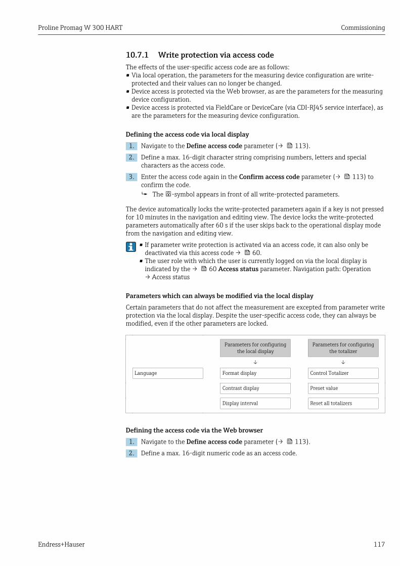
Proline Promag W 300 HART Commissioning
Endress+Hauser 117
10.7.1 Write protection via access codeThe effects of the user-specific access code are as follows:• Via local operation, the parameters for the measuring device configuration are write-
protected and their values can no longer be changed.• Device access is protected via the Web browser, as are the parameters for the measuring
device configuration.• Device access is protected via FieldCare or DeviceCare (via CDI-RJ45 service interface), as
are the parameters for the measuring device configuration.
Defining the access code via local display1. Navigate to the Define access code parameter (→ 113).
2. Define a max. 16-digit character string comprising numbers, letters and specialcharacters as the access code.
3. Enter the access code again in the Confirm access code parameter (→ 113) toconfirm the code. The -symbol appears in front of all write-protected parameters.
The device automatically locks the write-protected parameters again if a key is not pressedfor 10 minutes in the navigation and editing view. The device locks the write-protectedparameters automatically after 60 s if the user skips back to the operational display modefrom the navigation and editing view.
• If parameter write protection is activated via an access code, it can also only bedeactivated via this access code → 60.
• The user role with which the user is currently logged on via the local display isindicated by the → 60 Access status parameter. Navigation path: Operation→ Access status
Parameters which can always be modified via the local displayCertain parameters that do not affect the measurement are excepted from parameter writeprotection via the local display. Despite the user-specific access code, they can always bemodified, even if the other parameters are locked.
Parameters for configuringthe local display
Parameters for configuringthe totalizer
↓ ↓
Language Format display Control Totalizer
Contrast display Preset value
Display interval Reset all totalizers
Defining the access code via the Web browser1. Navigate to the Define access code parameter (→ 113).
2. Define a max. 16-digit numeric code as an access code.
Commissioning Proline Promag W 300 HART
118 Endress+Hauser
3. Enter the access code again in the Confirm access code parameter (→ 113) toconfirm the code. The Web browser switches to the login page.
If no action is performed for 10 minutes, the Web browser automatically returns tothe login page.
• If parameter write protection is activated via an access code, it can also only bedeactivated via this access code → 60.
• The user role with which the user is currently logged on via Web browser isindicated by the Access status parameter. Navigation path: Operation → Accessstatus
Resetting the access codeIf you misplace the user-specific access code, it is possible to reset the code to the factorysetting. A reset code must be entered for this purpose. The user-specific access code canthen be defined again afterwards.
Via Web browser, FieldCare, DeviceCare (via CDI-RJ45 service interface), fieldbusFor a reset code, contact your Endress+Hauser service organization.
1. Navigate to the Reset access code parameter (→ 113).
2. Enter the reset code. The access code has been reset to the factory setting 0000. It can be redefined
→ 117.
10.7.2 Write protection via write protection switchUnlike parameter write protection via a user-specific access code, this allows write accessto the entire operating menu - except for the "Contrast display" parameter - to be locked.
The parameter values are now read only and cannot be edited any more (exception"Contrast display" parameter):• Via local display• Via HART protocol
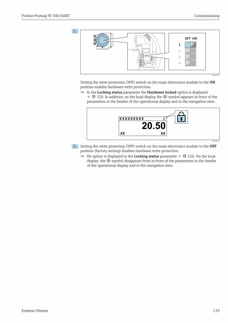
Proline Promag W 300 HART Commissioning
Endress+Hauser 119
1.
ONOFF
1
2
3
4
A0029630
Setting the write protection (WP) switch on the main electronics module to the ONposition enables hardware write protection. In the Locking status parameter the Hardware locked option is displayed
→ 120. In addition, on the local display the -symbol appears in front of theparameters in the header of the operational display and in the navigation view.
X X X X X X XX X
20.50XXXX
A0029425
2. Setting the write protection (WP) switch on the main electronics module to the OFFposition (factory setting) disables hardware write protection. No option is displayed in the Locking status parameter → 120. On the local
display, the -symbol disappears from in front of the parameters in the headerof the operational display and in the navigation view.
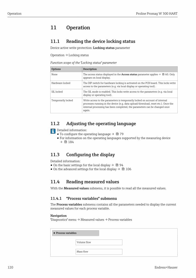
Operation Proline Promag W 300 HART
120 Endress+Hauser
11 Operation
11.1 Reading the device locking statusDevice active write protection: Locking status parameter
Operation → Locking status
Function scope of the "Locking status" parameter
Options Description
None The access status displayed in the Access status parameter applies → 60. Onlyappears on local display.
Hardware locked The DIP switch for hardware locking is activated on the PCB board. This locks writeaccess to the parameters (e.g. via local display or operating tool) .
SIL locked The SIL mode is enabled. This locks write access to the parameters (e.g. via localdisplay or operating tool).
Temporarily locked Write access to the parameters is temporarily locked on account of internalprocesses running in the device (e.g. data upload/download, reset etc.). Once theinternal processing has been completed, the parameters can be changed onceagain.
11.2 Adjusting the operating languageDetailed information:• To configure the operating language → 79• For information on the operating languages supported by the measuring device
→ 184
11.3 Configuring the displayDetailed information:• On the basic settings for the local display → 94• On the advanced settings for the local display → 106
11.4 Reading measured valuesWith the Measured values submenu, it is possible to read all the measured values.
11.4.1 "Process variables" submenuThe Process variables submenu contains all the parameters needed to display the currentmeasured values for each process variable.
Navigation"Diagnostics" menu → Measured values → Process variables
‣ Process variables
Volume flow
Mass flow

Proline Promag W 300 HART Operation
Endress+Hauser 121
Corrected volume flow
Flow velocity
Conductivity
Density
Parameter overview with brief description
Parameter Description User interface
Volume flow Displays the volume flow currently measured.
DependencyThe unit is taken from the Volume flow unit parameter(→ 82).
Signed floating-point number
Mass flow Displays the mass flow currently calculated.
DependencyThe unit is taken from the Mass flow unit parameter(→ 82).
Signed floating-point number
Corrected volume flow Displays the corrected volume flow currently calculated.
DependencyThe unit is taken from the Corrected volume flow unitparameter.
Signed floating-point number
Flow velocity Displays the flow velocity currently calculated. Signed floating-point number
Conductivity Displays the conductivity currently measured.
DependencyThe unit is taken from the Conductivity unit parameter.
Signed floating-point number
Density Displays the current fixed density or density read in from anexternal device.
DependencyThe unit is taken from the Density unit parameter.
Signed floating-point number
11.4.2 "Totalizer" submenuThe Totalizer submenu contains all the parameters needed to display the currentmeasured values for every totalizer.
Navigation"Diagnostics" menu → Measured values → Totalizer
‣ Totalizer
Totalizer value 1 to n → 122
Totalizer overflow 1 to n → 122
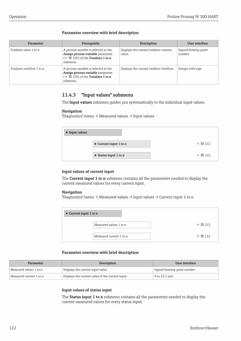
Operation Proline Promag W 300 HART
122 Endress+Hauser
Parameter overview with brief description
Parameter Prerequisite Description User interface
Totalizer value 1 to n A process variable is selected in theAssign process variable parameter(→ 105) of the Totalizer 1 to nsubmenu.
Displays the current totalizer countervalue.
Signed floating-pointnumber
Totalizer overflow 1 to n A process variable is selected in theAssign process variable parameter(→ 105) of the Totalizer 1 to nsubmenu.
Displays the current totalizer overflow. Integer with sign
11.4.3 "Input values" submenuThe Input values submenu guides you systematically to the individual input values.
Navigation"Diagnostics" menu → Measured values → Input values
‣ Input values
‣ Current input 1 to n → 122
‣ Status input 1 to n → 122
Input values of current inputThe Current input 1 to n submenu contains all the parameters needed to display thecurrent measured values for every current input.
Navigation"Diagnostics" menu → Measured values → Input values → Current input 1 to n
‣ Current input 1 to n
Measured values 1 to n → 122
Measured current 1 to n → 122
Parameter overview with brief description
Parameter Description User interface
Measured values 1 to n Displays the current input value. Signed floating-point number
Measured current 1 to n Displays the current value of the current input. 0 to 22.5 mA
Input values of status inputThe Status input 1 to n submenu contains all the parameters needed to display thecurrent measured values for every status input.
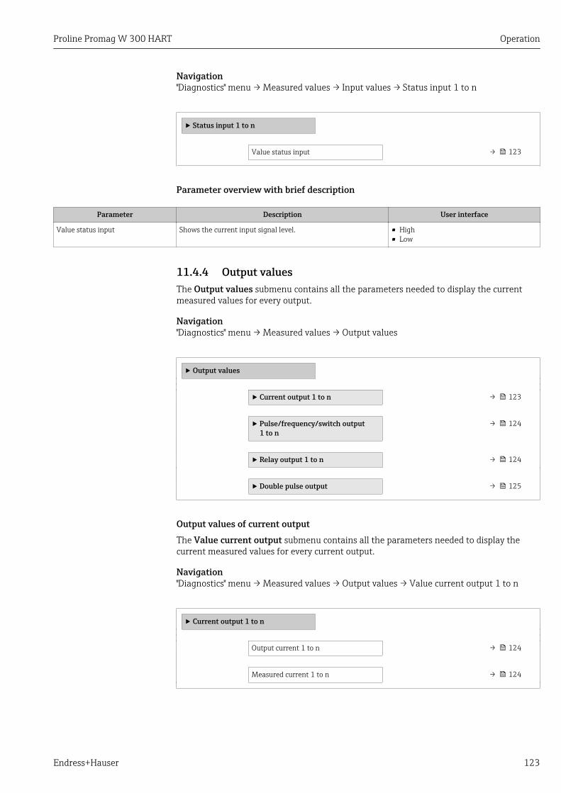
Proline Promag W 300 HART Operation
Endress+Hauser 123
Navigation"Diagnostics" menu → Measured values → Input values → Status input 1 to n
‣ Status input 1 to n
Value status input → 123
Parameter overview with brief description
Parameter Description User interface
Value status input Shows the current input signal level. • High• Low
11.4.4 Output valuesThe Output values submenu contains all the parameters needed to display the currentmeasured values for every output.
Navigation"Diagnostics" menu → Measured values → Output values
‣ Output values
‣ Current output 1 to n → 123
‣ Pulse/frequency/switch output1 to n
→ 124
‣ Relay output 1 to n → 124
‣ Double pulse output → 125
Output values of current outputThe Value current output submenu contains all the parameters needed to display thecurrent measured values for every current output.
Navigation"Diagnostics" menu → Measured values → Output values → Value current output 1 to n
‣ Current output 1 to n
Output current 1 to n → 124
Measured current 1 to n → 124
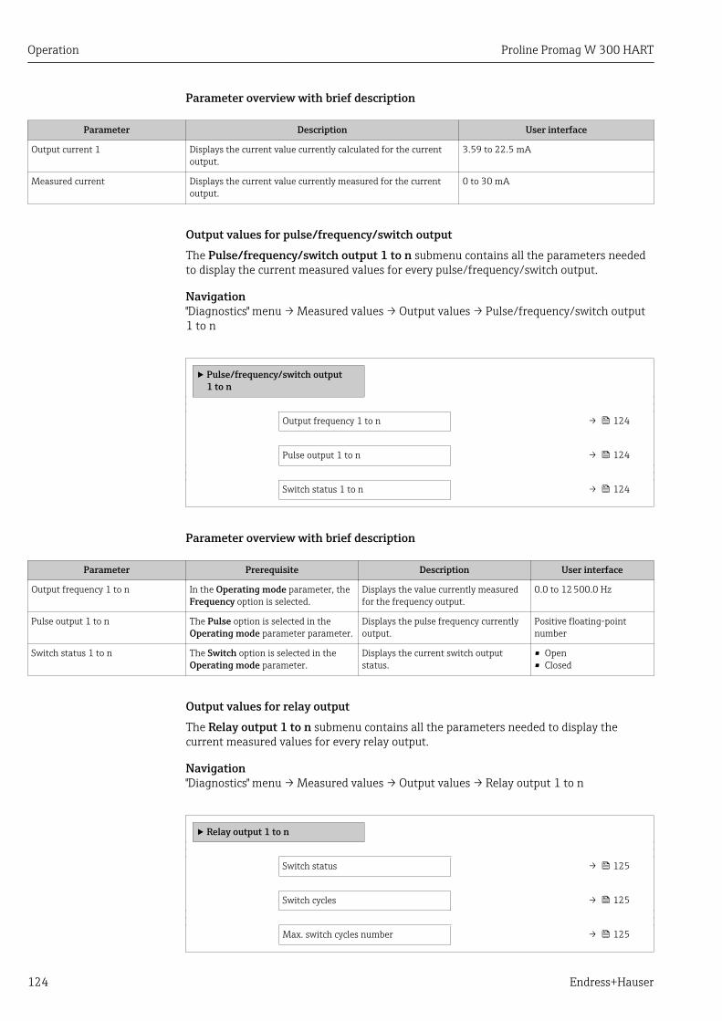
Operation Proline Promag W 300 HART
124 Endress+Hauser
Parameter overview with brief description
Parameter Description User interface
Output current 1 Displays the current value currently calculated for the currentoutput.
3.59 to 22.5 mA
Measured current Displays the current value currently measured for the currentoutput.
0 to 30 mA
Output values for pulse/frequency/switch outputThe Pulse/frequency/switch output 1 to n submenu contains all the parameters neededto display the current measured values for every pulse/frequency/switch output.
Navigation"Diagnostics" menu → Measured values → Output values → Pulse/frequency/switch output1 to n
‣ Pulse/frequency/switch output1 to n
Output frequency 1 to n → 124
Pulse output 1 to n → 124
Switch status 1 to n → 124
Parameter overview with brief description
Parameter Prerequisite Description User interface
Output frequency 1 to n In the Operating mode parameter, theFrequency option is selected.
Displays the value currently measuredfor the frequency output.
0.0 to 12 500.0 Hz
Pulse output 1 to n The Pulse option is selected in theOperating mode parameter parameter.
Displays the pulse frequency currentlyoutput.
Positive floating-pointnumber
Switch status 1 to n The Switch option is selected in theOperating mode parameter.
Displays the current switch outputstatus.
• Open• Closed
Output values for relay outputThe Relay output 1 to n submenu contains all the parameters needed to display thecurrent measured values for every relay output.
Navigation"Diagnostics" menu → Measured values → Output values → Relay output 1 to n
‣ Relay output 1 to n
Switch status → 125
Switch cycles → 125
Max. switch cycles number → 125
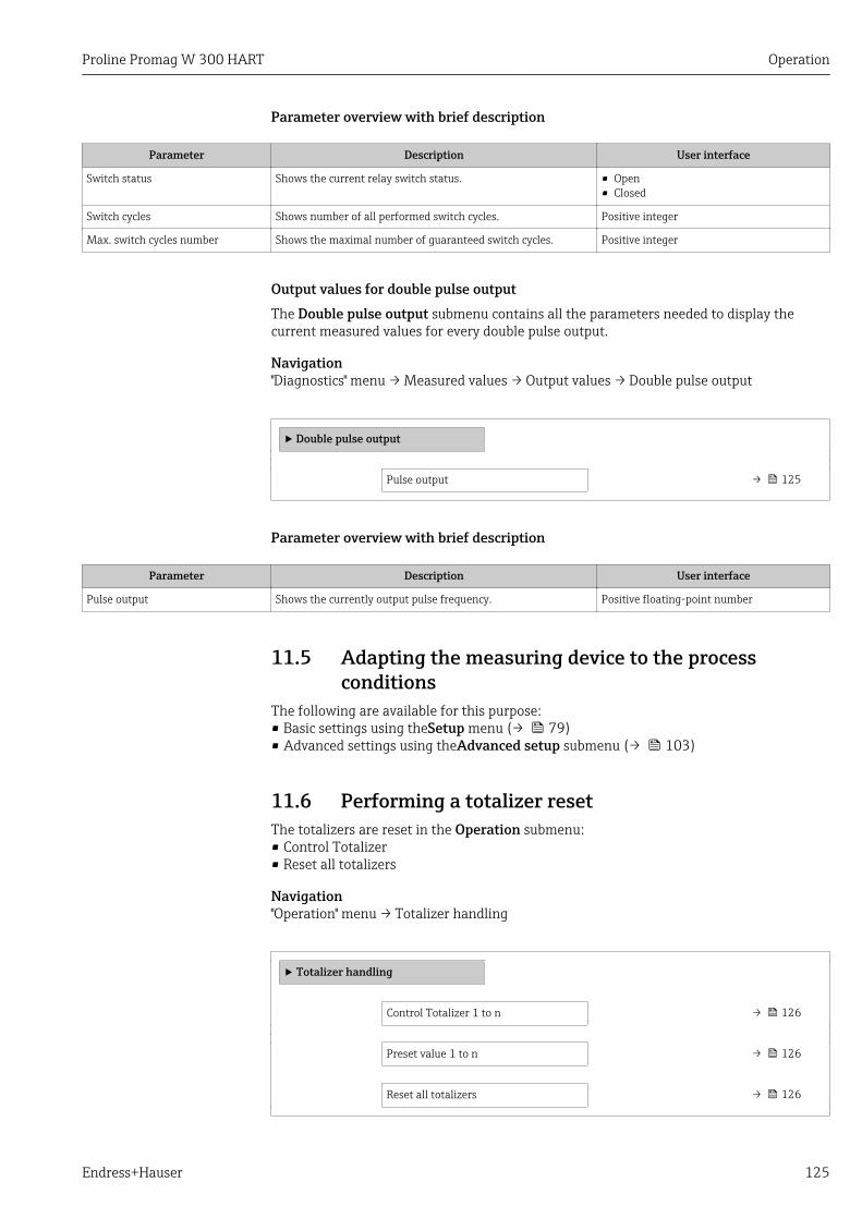
Proline Promag W 300 HART Operation
Endress+Hauser 125
Parameter overview with brief description
Parameter Description User interface
Switch status Shows the current relay switch status. • Open• Closed
Switch cycles Shows number of all performed switch cycles. Positive integer
Max. switch cycles number Shows the maximal number of guaranteed switch cycles. Positive integer
Output values for double pulse outputThe Double pulse output submenu contains all the parameters needed to display thecurrent measured values for every double pulse output.
Navigation"Diagnostics" menu → Measured values → Output values → Double pulse output
‣ Double pulse output
Pulse output → 125
Parameter overview with brief description
Parameter Description User interface
Pulse output Shows the currently output pulse frequency. Positive floating-point number
11.5 Adapting the measuring device to the processconditions
The following are available for this purpose:• Basic settings using theSetup menu (→ 79)• Advanced settings using theAdvanced setup submenu (→ 103)
11.6 Performing a totalizer resetThe totalizers are reset in the Operation submenu:• Control Totalizer• Reset all totalizers
Navigation"Operation" menu → Totalizer handling
‣ Totalizer handling
Control Totalizer 1 to n → 126
Preset value 1 to n → 126
Reset all totalizers → 126
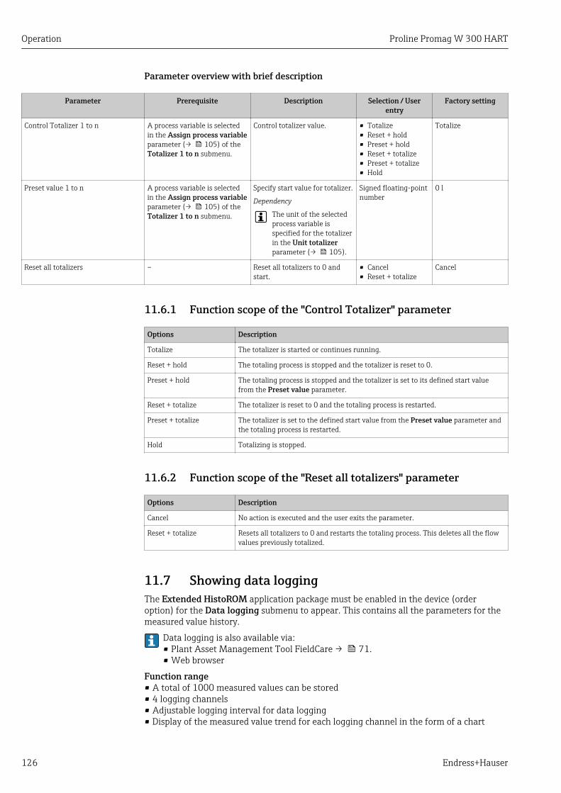
Operation Proline Promag W 300 HART
126 Endress+Hauser
Parameter overview with brief description
Parameter Prerequisite Description Selection / Userentry
Factory setting
Control Totalizer 1 to n A process variable is selectedin the Assign process variableparameter (→ 105) of theTotalizer 1 to n submenu.
Control totalizer value. • Totalize• Reset + hold• Preset + hold• Reset + totalize• Preset + totalize• Hold
Totalize
Preset value 1 to n A process variable is selectedin the Assign process variableparameter (→ 105) of theTotalizer 1 to n submenu.
Specify start value for totalizer.
Dependency
The unit of the selectedprocess variable isspecified for the totalizerin the Unit totalizerparameter (→ 105).
Signed floating-pointnumber
0 l
Reset all totalizers – Reset all totalizers to 0 andstart.
• Cancel• Reset + totalize
Cancel
11.6.1 Function scope of the "Control Totalizer" parameter
Options Description
Totalize The totalizer is started or continues running.
Reset + hold The totaling process is stopped and the totalizer is reset to 0.
Preset + hold The totaling process is stopped and the totalizer is set to its defined start valuefrom the Preset value parameter.
Reset + totalize The totalizer is reset to 0 and the totaling process is restarted.
Preset + totalize The totalizer is set to the defined start value from the Preset value parameter andthe totaling process is restarted.
Hold Totalizing is stopped.
11.6.2 Function scope of the "Reset all totalizers" parameter
Options Description
Cancel No action is executed and the user exits the parameter.
Reset + totalize Resets all totalizers to 0 and restarts the totaling process. This deletes all the flowvalues previously totalized.
11.7 Showing data loggingThe Extended HistoROM application package must be enabled in the device (orderoption) for the Data logging submenu to appear. This contains all the parameters for themeasured value history.
Data logging is also available via:• Plant Asset Management Tool FieldCare → 71.• Web browser
Function range• A total of 1000 measured values can be stored• 4 logging channels• Adjustable logging interval for data logging• Display of the measured value trend for each logging channel in the form of a chart

Proline Promag W 300 HART Operation
Endress+Hauser 127
0
/ ../XXXXXXXX
175.77
40.69 l/h
-100s
A0034352
• x-axis: depending on the number of channels selected displays 250 to 1000 measuredvalues of a process variable.
• y-axis: displays the approximate measured value span and constantly adapts this to theongoing measurement.
If the length of the logging interval or the assignment of the process variables to thechannels is changed, the content of the data logging is deleted.
Navigation"Diagnostics" menu → Data logging
‣ Data logging
Assign channel 1 → 128
Assign channel 2 → 128
Assign channel 3 → 128
Assign channel 4 → 128
Logging interval → 128
Clear logging data → 128
Data logging → 128
Logging delay → 128
Data logging control → 128
Data logging status → 129
Entire logging duration → 129
‣ Display channel 1
‣ Display channel 2
‣ Display channel 3
‣ Display channel 4
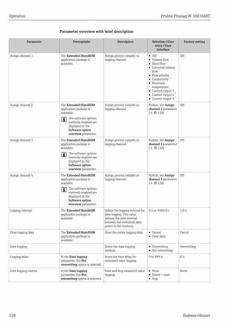
Operation Proline Promag W 300 HART
128 Endress+Hauser
Parameter overview with brief description
Parameter Prerequisite Description Selection / Userentry / User
interface
Factory setting
Assign channel 1 The Extended HistoROMapplication package isavailable.
Assign process variable tologging channel.
• Off• Volume flow• Mass flow• Corrected volume
flow• Flow velocity• Conductivity *
• Electronictemperature
• Current output 1• Current output 2 *
• Current output 3 *
Off
Assign channel 2 The Extended HistoROMapplication package isavailable.
The software optionscurrently enabled aredisplayed in theSoftware optionoverview parameter.
Assign process variable tologging channel.
Picklist, see Assignchannel 1 parameter(→ 128)
Off
Assign channel 3 The Extended HistoROMapplication package isavailable.
The software optionscurrently enabled aredisplayed in theSoftware optionoverview parameter.
Assign process variable tologging channel.
Picklist, see Assignchannel 1 parameter(→ 128)
Off
Assign channel 4 The Extended HistoROMapplication package isavailable.
The software optionscurrently enabled aredisplayed in theSoftware optionoverview parameter.
Assign process variable tologging channel.
Picklist, see Assignchannel 1 parameter(→ 128)
Off
Logging interval The Extended HistoROMapplication package isavailable.
Define the logging interval fordata logging. This valuedefines the time intervalbetween the individual datapoints in the memory.
0.1 to 3 600.0 s 1.0 s
Clear logging data The Extended HistoROMapplication package isavailable.
Clear the entire logging data. • Cancel• Clear data
Cancel
Data logging – Select the data loggingmethod.
• Overwriting• Not overwriting
Overwriting
Logging delay In the Data loggingparameter, the Notoverwriting option is selected.
Enter the time delay formeasured value logging.
0 to 999 h 0 h
Data logging control In the Data loggingparameter, the Notoverwriting option is selected.
Start and stop measured valuelogging.
• None• Delete + start• Stop
None

Proline Promag W 300 HART Operation
Endress+Hauser 129
Parameter Prerequisite Description Selection / Userentry / User
interface
Factory setting
Data logging status In the Data loggingparameter, the Notoverwriting option is selected.
Displays the measured valuelogging status.
• Done• Delay active• Active• Stopped
Done
Entire logging duration In the Data loggingparameter, the Notoverwriting option is selected.
Displays the total loggingduration.
Positive floating-point number
0 s
* Visibility depends on order options or device settings
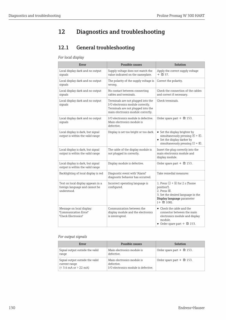
Diagnostics and troubleshooting Proline Promag W 300 HART
130 Endress+Hauser
12 Diagnostics and troubleshooting
12.1 General troubleshooting
For local display
Error Possible causes Solution
Local display dark and no outputsignals
Supply voltage does not match thevalue indicated on the nameplate.
Apply the correct supply voltage→ 37.
Local display dark and no outputsignals
The polarity of the supply voltage iswrong.
Correct the polarity.
Local display dark and no outputsignals
No contact between connectingcables and terminals.
Check the connection of the cablesand correct if necessary.
Local display dark and no outputsignals
Terminals are not plugged into theI/O electronics module correctly.Terminals are not plugged into themain electronics module correctly.
Check terminals.
Local display dark and no outputsignals
I/O electronics module is defective.Main electronics module isdefective.
Order spare part → 153.
Local display is dark, but signaloutput is within the valid range
Display is set too bright or too dark. • Set the display brighter bysimultaneously pressing + .
• Set the display darker bysimultaneously pressing + .
Local display is dark, but signaloutput is within the valid range
The cable of the display module isnot plugged in correctly.
Insert the plug correctly into themain electronics module anddisplay module.
Local display is dark, but signaloutput is within the valid range
Display module is defective. Order spare part → 153.
Backlighting of local display is red Diagnostic event with "Alarm"diagnostic behavior has occurred.
Take remedial measures
Text on local display appears in aforeign language and cannot beunderstood.
Incorrect operating language isconfigured.
1. Press + for 2 s ("homeposition").2. Press .3. Set the desired language in theDisplay language parameter(→ 108).
Message on local display:"Communication Error""Check Electronics"
Communication between thedisplay module and the electronicsis interrupted.
• Check the cable and theconnector between the mainelectronics module and displaymodule.
• Order spare part → 153.
For output signals
Error Possible causes Solution
Signal output outside the validrange
Main electronics module isdefective.
Order spare part → 153.
Signal output outside the validcurrent range(< 3.6 mA or > 22 mA)
Main electronics module isdefective.I/O electronics module is defective.
Order spare part → 153.
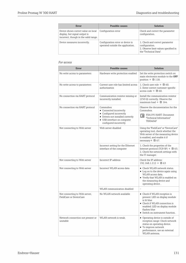
Proline Promag W 300 HART Diagnostics and troubleshooting
Endress+Hauser 131
Error Possible causes Solution
Device shows correct value on localdisplay, but signal output isincorrect, though in the valid range.
Configuration error Check and correct the parameterconfiguration.
Device measures incorrectly. Configuration error or device isoperated outside the application.
1. Check and correct parameterconfiguration.2. Observe limit values specified inthe "Technical Data".
For access
Error Possible causes Solution
No write access to parameters Hardware write protection enabled Set the write protection switch onmain electronics module to the OFFposition → 118.
No write access to parameters Current user role has limited accessauthorization
1. Check user role → 60.2. Enter correct customer-specificaccess code → 60.
No connection via HART protocol Communication resistor missing orincorrectly installed.
Install the communication resistor(250 Ω) correctly. Observe themaximum load → 164.
No connection via HART protocol Commubox• Connected incorrectly• Configured incorrectly• Drivers not installed correctly• USB interface on computer
configured incorrectly
Observe the documentation for theCommubox.
FXA195 HART: Document"Technical Information"TI00404F
Not connecting to Web server Web server disabled Using the "FieldCare" or "DeviceCare"operating tool, check whether theWeb server of the measuring deviceis enabled, and enable it ifnecessary→ 67.
Incorrect setting for the Ethernetinterface of the computer
1. Check the properties of theInternet protocol (TCP/IP) → 63.2. Check the network settings withthe IT manager.
Not connecting to Web server Incorrect IP address Check the IP address:192.168.1.212 → 63
Not connecting to Web server Incorrect WLAN access data • Check WLAN network status.• Log on to the device again using
WLAN access data.• Verify that WLAN is enabled on
the measuring device andoperating device .
WLAN communication disabled –
Not connecting to Web server,FieldCare or DeviceCare
No WLAN network available • Check if WLAN reception ispresent: LED on display moduleis lit blue
• Check if WLAN connection isenabled: LED on display moduleflashes blue
• Switch on instrument function.
Network connection not present orunstable
WLAN network is weak. • Operating device is outside ofreception range: Check networkstatus on operating device.
• To improve networkperformance, use an externalWLAN antenna.
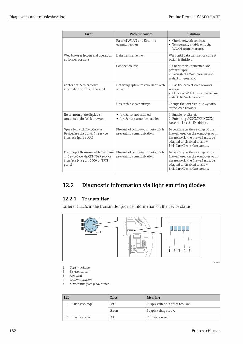
Diagnostics and troubleshooting Proline Promag W 300 HART
132 Endress+Hauser
Error Possible causes Solution
Parallel WLAN and Ethernetcommunication
• Check network settings.• Temporarily enable only the
WLAN as an interface.
Web browser frozen and operationno longer possible
Data transfer active Wait until data transfer or currentaction is finished.
Connection lost 1. Check cable connection andpower supply.2. Refresh the Web browser andrestart if necessary.
Content of Web browserincomplete or difficult to read
Not using optimum version of Webserver.
1. Use the correct Web browserversion .2. Clear the Web browser cache andrestart the Web browser.
Unsuitable view settings. Change the font size/display ratioof the Web browser.
No or incomplete display ofcontents in the Web browser
• JavaScript not enabled• JavaScript cannot be enabled
1. Enable JavaScript.2. Enter http://XXX.XXX.X.XXX/basic.html as the IP address.
Operation with FieldCare orDeviceCare via CDI-RJ45 serviceinterface (port 8000)
Firewall of computer or network ispreventing communication
Depending on the settings of thefirewall used on the computer or inthe network, the firewall must beadapted or disabled to allowFieldCare/DeviceCare access.
Flashing of firmware with FieldCareor DeviceCare via CDI-RJ45 serviceinterface (via port 8000 or TFTPports)
Firewall of computer or network ispreventing communication
Depending on the settings of thefirewall used on the computer or inthe network, the firewall must beadapted or disabled to allowFieldCare/DeviceCare access.
12.2 Diagnostic information via light emitting diodes
12.2.1 TransmitterDifferent LEDs in the transmitter provide information on the device status.
1 2 3 4 5
A0029629
1 Supply voltage2 Device status3 Not used4 Communication5 Service interface (CDI) active
LED Color Meaning
1 Supply voltage Off Supply voltage is off or too low.
Green Supply voltage is ok.
2 Device status Off Firmware error
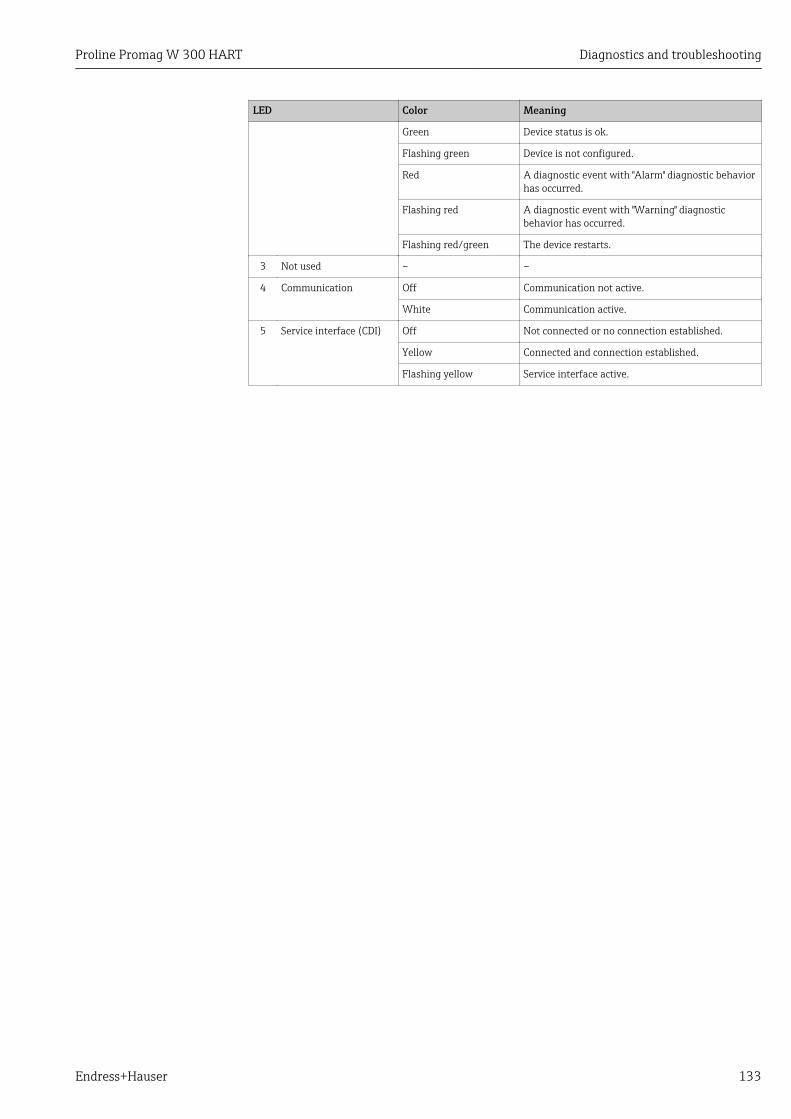
Proline Promag W 300 HART Diagnostics and troubleshooting
Endress+Hauser 133
LED Color Meaning
Green Device status is ok.
Flashing green Device is not configured.
Red A diagnostic event with "Alarm" diagnostic behaviorhas occurred.
Flashing red A diagnostic event with "Warning" diagnosticbehavior has occurred.
Flashing red/green The device restarts.
3 Not used – –
4 Communication Off Communication not active.
White Communication active.
5 Service interface (CDI) Off Not connected or no connection established.
Yellow Connected and connection established.
Flashing yellow Service interface active.
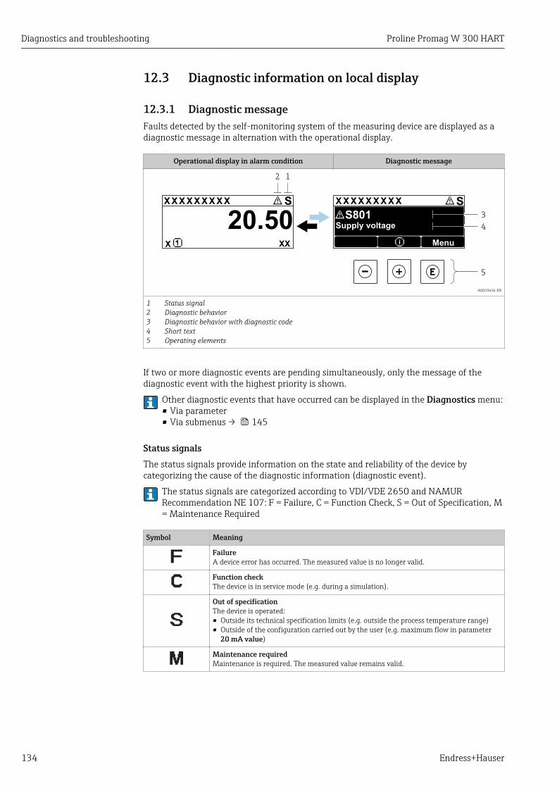
Diagnostics and troubleshooting Proline Promag W 300 HART
134 Endress+Hauser
12.3 Diagnostic information on local display
12.3.1 Diagnostic messageFaults detected by the self-monitoring system of the measuring device are displayed as adiagnostic message in alternation with the operational display.
Operational display in alarm condition Diagnostic message
1
4
3
X X X X X X XX X X X X X X X XX X
2
S S
XX
20.50
5
X i
S801
Menu
Supply voltage
A0029426-EN
12345
Status signalDiagnostic behaviorDiagnostic behavior with diagnostic codeShort textOperating elements
If two or more diagnostic events are pending simultaneously, only the message of thediagnostic event with the highest priority is shown.
Other diagnostic events that have occurred can be displayed in the Diagnostics menu:• Via parameter• Via submenus → 145
Status signalsThe status signals provide information on the state and reliability of the device bycategorizing the cause of the diagnostic information (diagnostic event).
The status signals are categorized according to VDI/VDE 2650 and NAMURRecommendation NE 107: F = Failure, C = Function Check, S = Out of Specification, M= Maintenance Required
Symbol Meaning
FailureA device error has occurred. The measured value is no longer valid.
Function checkThe device is in service mode (e.g. during a simulation).
Out of specificationThe device is operated:• Outside its technical specification limits (e.g. outside the process temperature range)• Outside of the configuration carried out by the user (e.g. maximum flow in parameter
20 mA value)
Maintenance requiredMaintenance is required. The measured value remains valid.
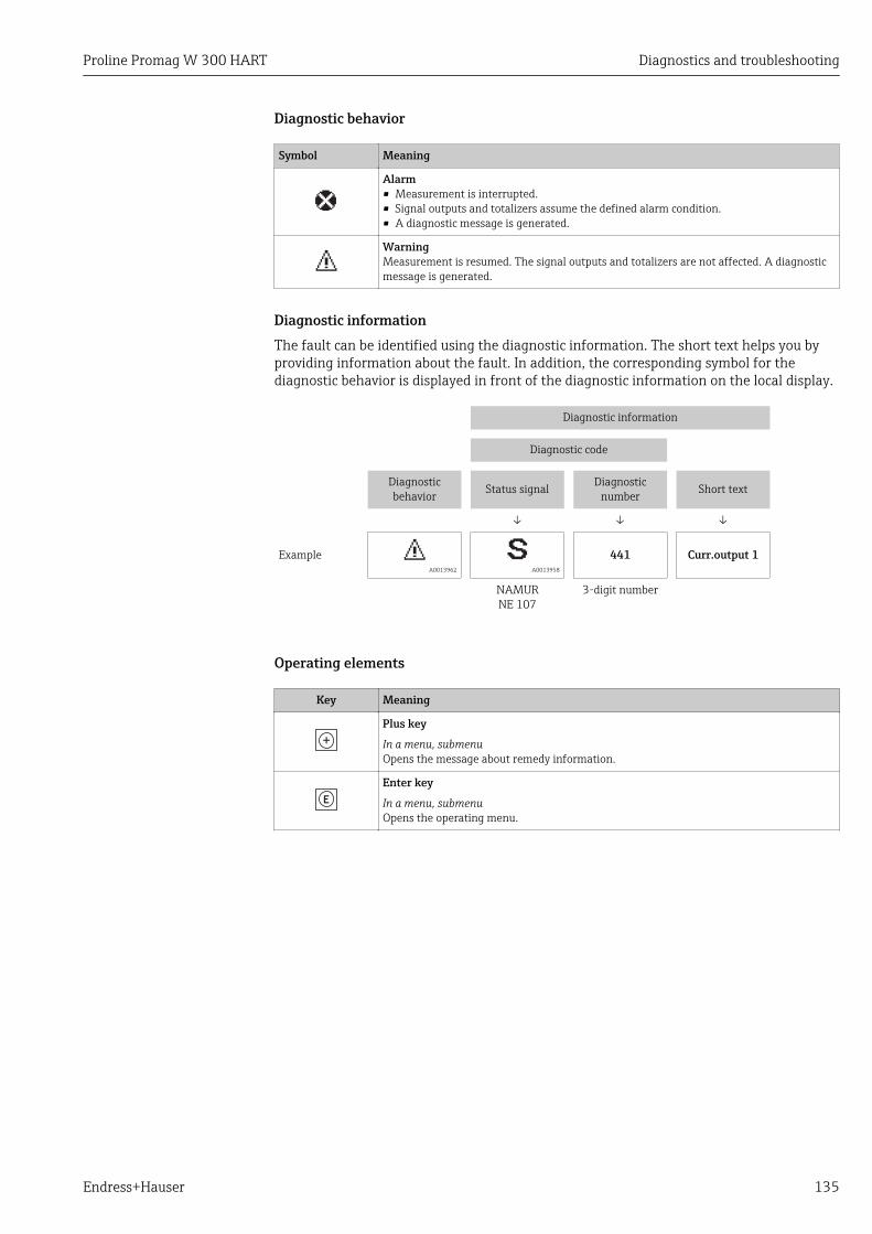
Proline Promag W 300 HART Diagnostics and troubleshooting
Endress+Hauser 135
Diagnostic behavior
Symbol Meaning
Alarm• Measurement is interrupted.• Signal outputs and totalizers assume the defined alarm condition.• A diagnostic message is generated.
WarningMeasurement is resumed. The signal outputs and totalizers are not affected. A diagnosticmessage is generated.
Diagnostic informationThe fault can be identified using the diagnostic information. The short text helps you byproviding information about the fault. In addition, the corresponding symbol for thediagnostic behavior is displayed in front of the diagnostic information on the local display.
Diagnostic information
Diagnostic code
Diagnosticbehavior Status signal Diagnostic
number Short text
↓ ↓ ↓
Example A0013962 A0013958
441 Curr.output 1
NAMURNE 107
3-digit number
Operating elements
Key Meaning
Plus key
In a menu, submenuOpens the message about remedy information.
Enter key
In a menu, submenuOpens the operating menu.

Diagnostics and troubleshooting Proline Promag W 300 HART
136 Endress+Hauser
12.3.2 Calling up remedial measures
X X X X X X XX X X X X X X X XX XS S
XX
20.50X i
S801
Menu
S
(ID:203)
S801 0d00h02m25s
1
2
4
6
3
5
1.
2.
3.
Increase supply voltage
S801 Supply voltage
Diagnostic list
Diagnostics 1
Diagnostics 2Diagnostics 3
Supply voltage
Supply voltage
A0029431-EN
32 Message about remedial measures
1 Diagnostic information2 Short text3 Service ID4 Diagnostic behavior with diagnostic code5 Operation time of occurrence6 Remedial measures
1. The user is in the diagnostic message.Press ( symbol). The Diagnostic list submenu opens.
2. Select the desired diagnostic event with or and press . The message about the remedial measures opens.
3. Press + simultaneously. The message about the remedial measures closes.
The user is in the Diagnostics menu at an entry for a diagnostics event, e.g. in theDiagnostic list submenu or Previous diagnostics parameter.
1. Press . The message for the remedial measures for the selected diagnostic event opens.
2. Press + simultaneously. The message for the remedial measures closes.
12.4 Diagnostic information in the Web browser
12.4.1 Diagnostic optionsAny faults detected by the measuring device are displayed in the Web browser on thehome page once the user has logged on.

Proline Promag W 300 HART Diagnostics and troubleshooting
Endress+Hauser 137
2 3
1
A0031056
1 Status area with status signal2 Diagnostic information→ 1353 Remedy information with Service ID
In addition, diagnostic events which have occurred can be shown in the Diagnosticsmenu:• Via parameter• Via submenu → 145
Status signalsThe status signals provide information on the state and reliability of the device bycategorizing the cause of the diagnostic information (diagnostic event).
Symbol Meaning
FailureA device error has occurred. The measured value is no longer valid.
Function checkThe device is in service mode (e.g. during a simulation).
Out of specificationThe device is operated:• Outside its technical specification limits (e.g. outside the process temperature range)• Outside of the configuration carried out by the user (e.g. maximum flow in parameter
20 mA value)
Maintenance requiredMaintenance is required. The measured value is still valid.
The status signals are categorized in accordance with VDI/VDE 2650 and NAMURRecommendation NE 107.
12.4.2 Calling up remedy informationRemedy information is provided for every diagnostic event to ensure that problems can berectified quickly. These measures are displayed in red along with the diagnostic event andthe related diagnostic information.
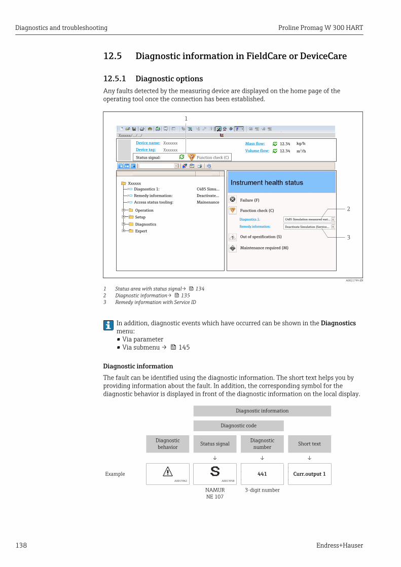
Diagnostics and troubleshooting Proline Promag W 300 HART
138 Endress+Hauser
12.5 Diagnostic information in FieldCare or DeviceCare
12.5.1 Diagnostic optionsAny faults detected by the measuring device are displayed on the home page of theoperating tool once the connection has been established.
Xxxxxx/…/…/
Xxxxxx
P
P
P
+
+
+
+Diagnostics 1:
Remedy information:
Failure (F)
Function check (C)
Out of spezification (S)
Maintenance required (M)
C485 Simulation measured vari...
Deactivate Simulation (Service...
Diagnostics 1: C485 Simu...
Remedy information: Deactivate...
Access status tooling: Mainenance
Operation
Setup
Diagnostics
Expert
Function check (C)Status signal:
Device tag:
Device name: Mass flow:
Volume flow:Xxxxxxx
12.34 kg/h
12.34 m /h³
Xxxxxxx
1
2
3
A0021799-EN
1 Status area with status signal→ 1342 Diagnostic information→ 1353 Remedy information with Service ID
In addition, diagnostic events which have occurred can be shown in the Diagnosticsmenu:• Via parameter• Via submenu → 145
Diagnostic informationThe fault can be identified using the diagnostic information. The short text helps you byproviding information about the fault. In addition, the corresponding symbol for thediagnostic behavior is displayed in front of the diagnostic information on the local display.
Diagnostic information
Diagnostic code
Diagnosticbehavior Status signal Diagnostic
number Short text
↓ ↓ ↓
Example A0013962 A0013958
441 Curr.output 1
NAMURNE 107
3-digit number

Proline Promag W 300 HART Diagnostics and troubleshooting
Endress+Hauser 139
12.5.2 Calling up remedy informationRemedy information is provided for every diagnostic event to ensure that problems can berectified quickly:• On the home page
Remedy information is displayed in a separate field below the diagnostics information.• In the Diagnostics menu
Remedy information can be called up in the working area of the user interface.
The user is in the Diagnostics menu.
1. Call up the desired parameter.
2. On the right in the working area, mouse over the parameter. A tool tip with remedy information for the diagnostic event appears.
12.6 Adapting the diagnostic information
12.6.1 Adapting the diagnostic behaviorEach item of diagnostic information is assigned a specific diagnostic behavior at thefactory. The user can change this assignment for specific diagnostic information in theDiagnostic behavior submenu.
Expert → System → Diagnostic handling → Diagnostic behavior
0723-1
Diagnostic no. 044
/ ../Diagn. behavior
Diagnostic no. 801
Diagnostic no. 274Warning
A0014048-EN
33 Taking the example of the local display
You can assign the following options to the diagnostic number as the diagnostic behavior:
Options Description
Alarm The device stops measurement. The signal outputs and totalizers assume the definedalarm condition. A diagnostic message is generated.The background lighting changes to red.
Warning The device continues to measure. The signal outputs and totalizers are not affected. Adiagnostic message is generated.
Logbook entry only The device continues to measure. The diagnostic message is displayed only in the Eventlogbook submenu (Event list submenu) and is not displayed in alternation with theoperational display.
Off The diagnostic event is ignored, and no diagnostic message is generated or entered.
12.6.2 Adapting the status signalEach item of diagnostic information is assigned a specific status signal at the factory. Theuser can change this assignment for specific diagnostic information in the Diagnosticevent category submenu.
Expert → Communication → Diagnostic event category
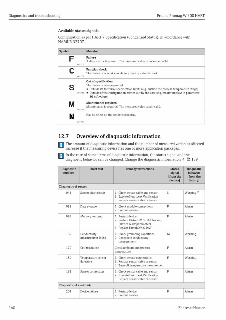
Diagnostics and troubleshooting Proline Promag W 300 HART
140 Endress+Hauser
Available status signalsConfiguration as per HART 7 Specification (Condensed Status), in accordance withNAMUR NE107.
Symbol Meaning
A0013956
FailureA device error is present. The measured value is no longer valid.
A0013959
Function checkThe device is in service mode (e.g. during a simulation).
A0013958
Out of specificationThe device is being operated:• Outside its technical specification limits (e.g. outside the process temperature range)• Outside of the configuration carried out by the user (e.g. maximum flow in parameter
20 mA value)
A0013957
Maintenance requiredMaintenance is required. The measured value is still valid.
A0023076
Has no effect on the condensed status.
12.7 Overview of diagnostic information The amount of diagnostic information and the number of measured variables affectedincrease if the measuring device has one or more application packages.
In the case of some items of diagnostic information, the status signal and thediagnostic behavior can be changed. Change the diagnostic information → 139
Diagnosticnumber
Short text Remedy instructions Statussignal
[from thefactory]
Diagnosticbehavior[from thefactory]
Diagnostic of sensor
043 Sensor short circuit 1. Check sensor cable and sensor2. Execute Heartbeat Verification3. Replace sensor cable or sensor
S Warning 1)
082 Data storage 1. Check module connections2. Contact service
F Alarm
083 Memory content 1. Restart device2. Restore HistoROM S-DAT backup
('Device reset' parameter)3. Replace HistoROM S-DAT
F Alarm
169 Conductivitymeasurement failed
1. Check grounding conditions2. Deactivate conductivity
measurement
M Warning
170 Coil resistance Check ambient and processtemperature
F Alarm
180 Temperature sensordefective
1. Check sensor connections2. Replace sensor cable or sensor3. Turn off temperature measurement
F Warning
181 Sensor connection 1. Check sensor cable and sensor2. Execute Heartbeat Verification3. Replace sensor cable or sensor
F Alarm
Diagnostic of electronic
201 Device failure 1. Restart device2. Contact service
F Alarm
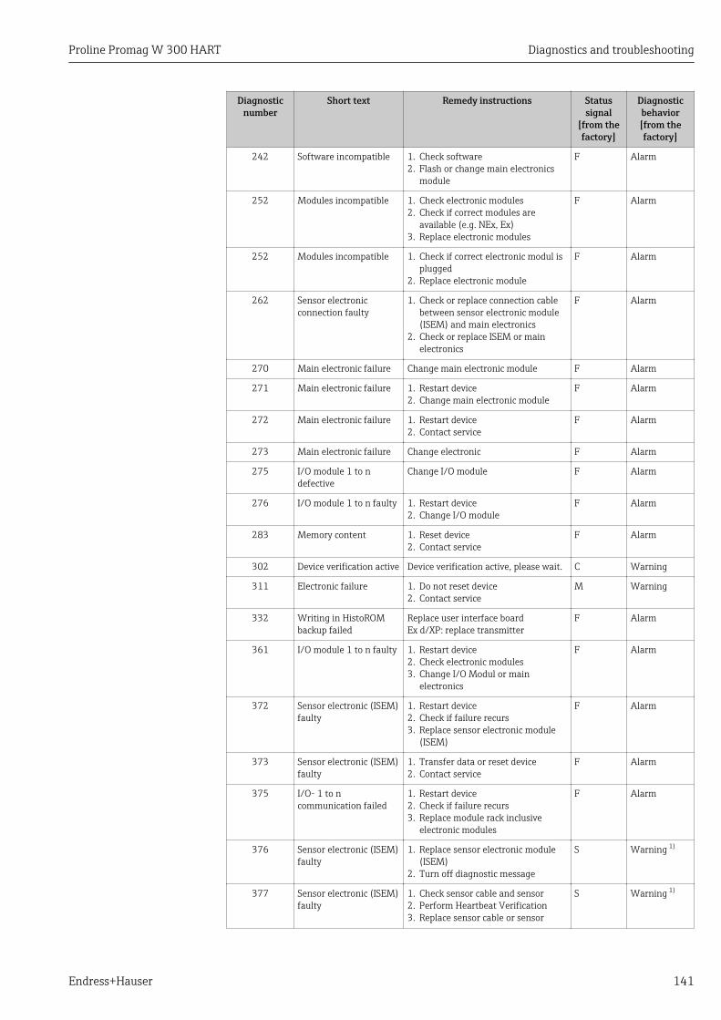
Proline Promag W 300 HART Diagnostics and troubleshooting
Endress+Hauser 141
Diagnosticnumber
Short text Remedy instructions Statussignal
[from thefactory]
Diagnosticbehavior[from thefactory]
242 Software incompatible 1. Check software2. Flash or change main electronics
module
F Alarm
252 Modules incompatible 1. Check electronic modules2. Check if correct modules are
available (e.g. NEx, Ex)3. Replace electronic modules
F Alarm
252 Modules incompatible 1. Check if correct electronic modul isplugged
2. Replace electronic module
F Alarm
262 Sensor electronicconnection faulty
1. Check or replace connection cablebetween sensor electronic module(ISEM) and main electronics
2. Check or replace ISEM or mainelectronics
F Alarm
270 Main electronic failure Change main electronic module F Alarm
271 Main electronic failure 1. Restart device2. Change main electronic module
F Alarm
272 Main electronic failure 1. Restart device2. Contact service
F Alarm
273 Main electronic failure Change electronic F Alarm
275 I/O module 1 to ndefective
Change I/O module F Alarm
276 I/O module 1 to n faulty 1. Restart device2. Change I/O module
F Alarm
283 Memory content 1. Reset device2. Contact service
F Alarm
302 Device verification active Device verification active, please wait. C Warning
311 Electronic failure 1. Do not reset device2. Contact service
M Warning
332 Writing in HistoROMbackup failed
Replace user interface boardEx d/XP: replace transmitter
F Alarm
361 I/O module 1 to n faulty 1. Restart device2. Check electronic modules3. Change I/O Modul or main
electronics
F Alarm
372 Sensor electronic (ISEM)faulty
1. Restart device2. Check if failure recurs3. Replace sensor electronic module
(ISEM)
F Alarm
373 Sensor electronic (ISEM)faulty
1. Transfer data or reset device2. Contact service
F Alarm
375 I/O- 1 to ncommunication failed
1. Restart device2. Check if failure recurs3. Replace module rack inclusive
electronic modules
F Alarm
376 Sensor electronic (ISEM)faulty
1. Replace sensor electronic module(ISEM)
2. Turn off diagnostic message
S Warning 1)
377 Sensor electronic (ISEM)faulty
1. Check sensor cable and sensor2. Perform Heartbeat Verification3. Replace sensor cable or sensor
S Warning 1)
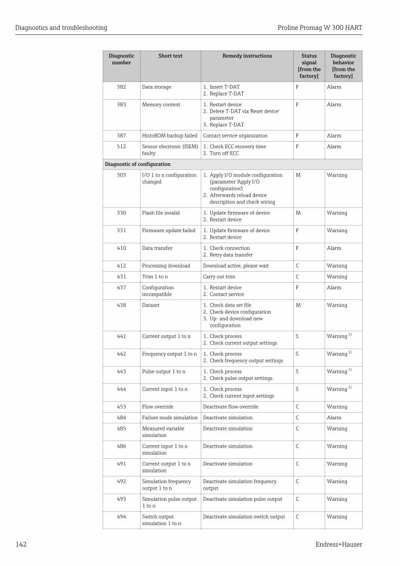
Diagnostics and troubleshooting Proline Promag W 300 HART
142 Endress+Hauser
Diagnosticnumber
Short text Remedy instructions Statussignal
[from thefactory]
Diagnosticbehavior[from thefactory]
382 Data storage 1. Insert T-DAT2. Replace T-DAT
F Alarm
383 Memory content 1. Restart device2. Delete T-DAT via 'Reset device'
parameter3. Replace T-DAT
F Alarm
387 HistoROM backup failed Contact service organization F Alarm
512 Sensor electronic (ISEM)faulty
1. Check ECC recovery time2. Turn off ECC
F Alarm
Diagnostic of configuration
303 I/O 1 to n configurationchanged
1. Apply I/O module configuration(parameter 'Apply I/Oconfiguration')
2. Afterwards reload devicedescription and check wiring
M Warning
330 Flash file invalid 1. Update firmware of device2. Restart device
M Warning
331 Firmware update failed 1. Update firmware of device2. Restart device
F Warning
410 Data transfer 1. Check connection2. Retry data transfer
F Alarm
412 Processing download Download active, please wait C Warning
431 Trim 1 to n Carry out trim C Warning
437 Configurationincompatible
1. Restart device2. Contact service
F Alarm
438 Dataset 1. Check data set file2. Check device configuration3. Up- and download new
configuration
M Warning
441 Current output 1 to n 1. Check process2. Check current output settings
S Warning 1)
442 Frequency output 1 to n 1. Check process2. Check frequency output settings
S Warning 1)
443 Pulse output 1 to n 1. Check process2. Check pulse output settings
S Warning 1)
444 Current input 1 to n 1. Check process2. Check current input settings
S Warning 1)
453 Flow override Deactivate flow override C Warning
484 Failure mode simulation Deactivate simulation C Alarm
485 Measured variablesimulation
Deactivate simulation C Warning
486 Current input 1 to nsimulation
Deactivate simulation C Warning
491 Current output 1 to nsimulation
Deactivate simulation C Warning
492 Simulation frequencyoutput 1 to n
Deactivate simulation frequencyoutput
C Warning
493 Simulation pulse output1 to n
Deactivate simulation pulse output C Warning
494 Switch outputsimulation 1 to n
Deactivate simulation switch output C Warning

Proline Promag W 300 HART Diagnostics and troubleshooting
Endress+Hauser 143
Diagnosticnumber
Short text Remedy instructions Statussignal
[from thefactory]
Diagnosticbehavior[from thefactory]
495 Diagnostic eventsimulation
Deactivate simulation C Warning
496 Status input simulation Deactivate simulation status input C Warning
502 CT activation/deactivation failed
Follow the sequence of the custodytransfer activation/deactivation: Firstauthorized user login, then set the DIPswitch on the main electonic module
C Warning
511 ISEM settings faulty 1. Check measuring period andintegration time
2. Check sensor properties
C Alarm
520 I/O 1 to n hardwareconfiguration invalid
1. Check I/O hardware configuration2. Replace wrong I/O module3. Plug the module of double pulse
output on correct slot
F Alarm
530 Electrode cleaning isrunning
Turn off ECC C Warning
531 Empty pipe adjustmentfaulty
Execute EPD adjustment S Warning 1)
537 Configuration 1. Check IP addresses in network2. Change IP address
F Warning
540 Custody transfer modefailed
1. Check electronic components2. Check parameter settings3. Deactivate custody transfer mode4. Reactivate custody transfer mode
F Alarm
543 Double pulse output 1. Check process2. Check pulse output settings
S Warning 1)
593 Double pulse outputsimulation
Deactivate simulation pulse output C Warning
594 Relay output simulation Deactivate simulation switch output C Warning
599 Custody transferlogbook full
1. Deactivate custody transfer mode2. Clear custody transfer logbook (all
30 entries)3. Activate custody transfer mode
F Warning
Diagnostic of process
803 Current loop 1. Check wiring2. Change I/O module
F Alarm
832 Electronic temperaturetoo high
Reduce ambient temperature S Warning 1)
833 Electronic temperaturetoo low
Increase ambient temperature S Warning 1)
834 Process temperature toohigh
Reduce process temperature S Warning 1)
835 Process temperature toolow
Increase process temperature S Warning 1)
842 Process limit Low flow cut off active!1. Check low flow cut off
configuration
S Warning
882 Input signal 1. Check input configuration2. Check external device or process
conditions
F Alarm
937 Sensor symmetry 1. Eliminate external magnetic fieldnear sensor
2. Turn off diagnostic message
S Warning 1)
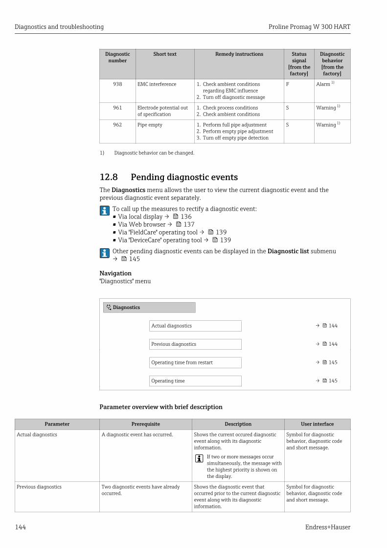
Diagnostics and troubleshooting Proline Promag W 300 HART
144 Endress+Hauser
Diagnosticnumber
Short text Remedy instructions Statussignal
[from thefactory]
Diagnosticbehavior[from thefactory]
938 EMC interference 1. Check ambient conditionsregarding EMC influence
2. Turn off diagnostic message
F Alarm 1)
961 Electrode potential outof specification
1. Check process conditions2. Check ambient conditions
S Warning 1)
962 Pipe empty 1. Perform full pipe adjustment2. Perform empty pipe adjustment3. Turn off empty pipe detection
S Warning 1)
1) Diagnostic behavior can be changed.
12.8 Pending diagnostic eventsThe Diagnostics menu allows the user to view the current diagnostic event and theprevious diagnostic event separately.
To call up the measures to rectify a diagnostic event:• Via local display → 136• Via Web browser → 137• Via "FieldCare" operating tool → 139• Via "DeviceCare" operating tool → 139
Other pending diagnostic events can be displayed in the Diagnostic list submenu→ 145
Navigation"Diagnostics" menu
Diagnostics
Actual diagnostics → 144
Previous diagnostics → 144
Operating time from restart → 145
Operating time → 145
Parameter overview with brief description
Parameter Prerequisite Description User interface
Actual diagnostics A diagnostic event has occurred. Shows the current occured diagnosticevent along with its diagnosticinformation.
If two or more messages occursimultaneously, the message withthe highest priority is shown onthe display.
Symbol for diagnosticbehavior, diagnostic codeand short message.
Previous diagnostics Two diagnostic events have alreadyoccurred.
Shows the diagnostic event thatoccurred prior to the current diagnosticevent along with its diagnosticinformation.
Symbol for diagnosticbehavior, diagnostic codeand short message.

Proline Promag W 300 HART Diagnostics and troubleshooting
Endress+Hauser 145
Parameter Prerequisite Description User interface
Operating time from restart – Shows the time the device has been inoperation since the last device restart.
Days (d), hours (h),minutes (m) and seconds(s)
Operating time – Indicates how long the device has beenin operation.
Days (d), hours (h),minutes (m) and seconds(s)
12.9 Diagnostic listUp to 5 currently pending diagnostic events can be displayed in the Diagnostic listsubmenu along with the associated diagnostic information. If more than 5 diagnosticevents are pending, the events with the highest priority are shown on the display.
Navigation pathDiagnostics → Diagnostic list
Diagnostics
/ ../Diagnose list
Diagnostics 3
Diagnostics 2
F273 Main electronic
A0014006-EN
34 Taking the example of the local display
To call up the measures to rectify a diagnostic event:• Via local display → 136• Via Web browser → 137• Via "FieldCare" operating tool → 139• Via "DeviceCare" operating tool → 139
12.10 Event logbook
12.10.1 Reading out the event logbookA chronological overview of the event messages that have occurred is provided in theEvents list submenu.
Navigation pathDiagnostics menu → Event logbook submenu → Event list
FI1091 Config. change
I1157 Mem.err. ev.list
F311 Electr. failure
/ ../Eventlist
0d01h19m10s
A0014008-EN
35 Taking the example of the local display
• A maximum of 20 event messages can be displayed in chronological order.• If the Extended HistoROM application package (order option) is enabled in the device,
the event list can contain up to 100 entries .
The event history includes entries for:• Diagnostic events → 140• Information events → 146
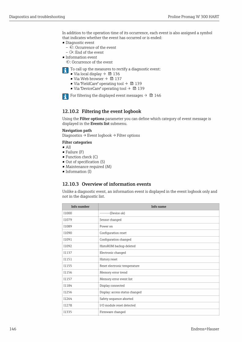
Diagnostics and troubleshooting Proline Promag W 300 HART
146 Endress+Hauser
In addition to the operation time of its occurrence, each event is also assigned a symbolthat indicates whether the event has occurred or is ended:• Diagnostic event
– : Occurrence of the event– : End of the event
• Information event: Occurrence of the event
To call up the measures to rectify a diagnostic event:• Via local display → 136• Via Web browser → 137• Via "FieldCare" operating tool → 139• Via "DeviceCare" operating tool → 139
For filtering the displayed event messages → 146
12.10.2 Filtering the event logbookUsing the Filter options parameter you can define which category of event message isdisplayed in the Events list submenu.
Navigation pathDiagnostics → Event logbook → Filter options
Filter categories• All• Failure (F)• Function check (C)• Out of specification (S)• Maintenance required (M)• Information (I)
12.10.3 Overview of information eventsUnlike a diagnostic event, an information event is displayed in the event logbook only andnot in the diagnostic list.
Info number Info name
I1000 --------(Device ok)
I1079 Sensor changed
I1089 Power on
I1090 Configuration reset
I1091 Configuration changed
I1092 HistoROM backup deleted
I1137 Electronic changed
I1151 History reset
I1155 Reset electronic temperature
I1156 Memory error trend
I1157 Memory error event list
I1184 Display connected
I1256 Display: access status changed
I1264 Safety sequence aborted
I1278 I/O module reset detected
I1335 Firmware changed
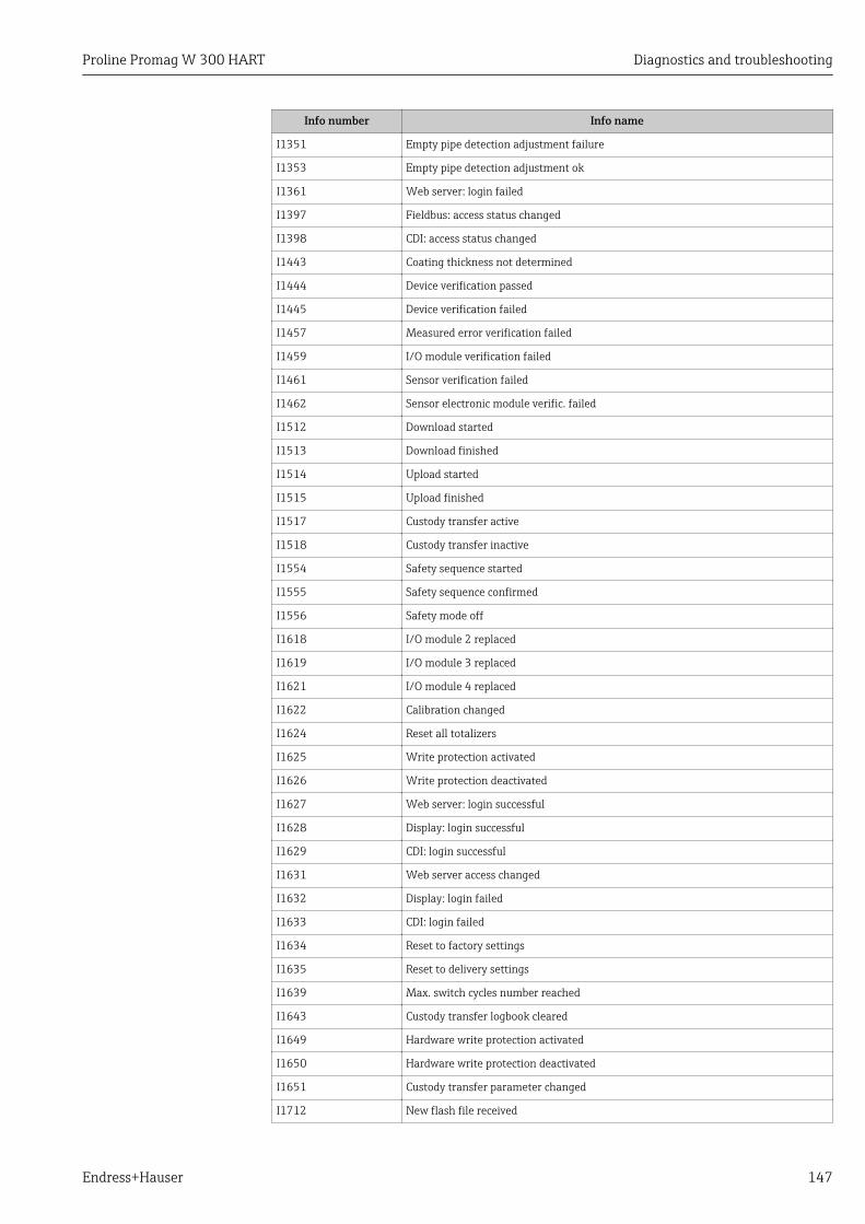
Proline Promag W 300 HART Diagnostics and troubleshooting
Endress+Hauser 147
Info number Info name
I1351 Empty pipe detection adjustment failure
I1353 Empty pipe detection adjustment ok
I1361 Web server: login failed
I1397 Fieldbus: access status changed
I1398 CDI: access status changed
I1443 Coating thickness not determined
I1444 Device verification passed
I1445 Device verification failed
I1457 Measured error verification failed
I1459 I/O module verification failed
I1461 Sensor verification failed
I1462 Sensor electronic module verific. failed
I1512 Download started
I1513 Download finished
I1514 Upload started
I1515 Upload finished
I1517 Custody transfer active
I1518 Custody transfer inactive
I1554 Safety sequence started
I1555 Safety sequence confirmed
I1556 Safety mode off
I1618 I/O module 2 replaced
I1619 I/O module 3 replaced
I1621 I/O module 4 replaced
I1622 Calibration changed
I1624 Reset all totalizers
I1625 Write protection activated
I1626 Write protection deactivated
I1627 Web server: login successful
I1628 Display: login successful
I1629 CDI: login successful
I1631 Web server access changed
I1632 Display: login failed
I1633 CDI: login failed
I1634 Reset to factory settings
I1635 Reset to delivery settings
I1639 Max. switch cycles number reached
I1643 Custody transfer logbook cleared
I1649 Hardware write protection activated
I1650 Hardware write protection deactivated
I1651 Custody transfer parameter changed
I1712 New flash file received

Diagnostics and troubleshooting Proline Promag W 300 HART
148 Endress+Hauser
Info number Info name
I1725 Sensor electronic module (ISEM) changed
I1726 Configuration backup failed
12.11 Resetting the measuring deviceUsing theDevice reset parameter (→ 114) it is possible to reset the entire deviceconfiguration or some of the configuration to a defined state.
12.11.1 Function scope of the "Device reset" parameter
Options Description
Cancel No action is executed and the user exits the parameter.
To delivery settings Every parameter for which a customer-specific default setting was ordered is resetto this customer-specific value. All other parameters are reset to the factorysetting.
Restart device The restart resets every parameter whose data are in the volatile memory (RAM)to the factory setting (e.g. measured value data). The device configuration remainsunchanged.
Restore S-DAT backup Restore the data that are saved on the S-DAT. The data record is restored from theelectronics memory to the S-DAT.
This option is displayed only in an alarm condition.
12.12 Device informationThe Device information submenu contains all parameters that display differentinformation for device identification.
Navigation"Diagnostics" menu → Device information
‣ Device information
Device tag → 149
Serial number → 149
Firmware version → 149
Device name → 149
Order code → 149
Extended order code 1 → 149
Extended order code 2 → 149
Extended order code 3 → 149

Proline Promag W 300 HART Diagnostics and troubleshooting
Endress+Hauser 149
ENP version → 149
Device revision → 149
Device ID → 149
Device type → 150
Manufacturer ID → 150
Parameter overview with brief description
Parameter Description User interface Factory setting
Device tag Shows name of measuring point. Max. 32 characters, such asletters, numbers or specialcharacters (e.g. @, %, /).
Promag
Serial number Shows the serial number of the measuringdevice.
Max. 11-digit character stringcomprising letters andnumbers.
–
Firmware version Shows the device firmware version installed. Character string in the formatxx.yy.zz
–
Device name Shows the name of the transmitter.
The name can be found on thenameplate of the transmitter.
Promag 300/500 –
Order code Shows the device order code.
The order code can be found on thenameplate of the sensor andtransmitter in the "Order code" field.
Character string composed ofletters, numbers and certainpunctuation marks (e.g. /).
–
Extended order code 1 Shows the 1st part of the extended ordercode.
The extended order code can also befound on the nameplate of the sensorand transmitter in the "Ext. ord. cd."field.
Character string –
Extended order code 2 Shows the 2nd part of the extended ordercode.
The extended order code can also befound on the nameplate of the sensorand transmitter in the "Ext. ord. cd."field.
Character string –
Extended order code 3 Shows the 3rd part of the extended ordercode.
The extended order code can also befound on the nameplate of the sensorand transmitter in the "Ext. ord. cd."field.
Character string –
ENP version Shows the version of the electronicnameplate (ENP).
Character string 2.02.00
Device revision Shows the device revision with which thedevice is registered with the HARTCommunication Foundation.
2-digit hexadecimal number 2
Device ID Shows the device ID for identifying thedevice in a HART network.
6-digit hexadecimal number –

Diagnostics and troubleshooting Proline Promag W 300 HART
150 Endress+Hauser
Parameter Description User interface Factory setting
Device type Shows the device type with which themeasuring device is registered with theHART Communication Foundation.
2-digit hexadecimal number 0x3A (for Promag 300)
Manufacturer ID Shows the manufacturer ID device isregistered with the HART CommunicationFoundation.
2-digit hexadecimal number 0x11 (for Endress+Hauser)
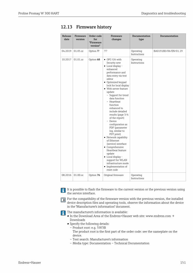
Proline Promag W 300 HART Diagnostics and troubleshooting
Endress+Hauser 151
12.13 Firmware history
Releasedate
Firmwareversion
Order codefor
"Firmwareversion"
Firmwarechanges
Documentationtype
Documentation
04.2019 01.05.zz Option ?? ??? OperatingInstructions
BA01918D/06/EN/01.19
10.2017 01.01.zz Option 68 • OPC-UA withSecurity new
• Local display -enhancedperformance anddata entry via texteditor
• Optimized keypadlock for local display
• Web server featureupdate– Support for trend
data function– Heartbeat
functionenhanced toinclude detailedresults (page 3/4of the report)
– Deviceconfiguration asPDF (parameterlog, similar toFDT print)
• Network capabilityof Ethernet(service) interface
• ComprehensiveHeartbeat featureupdate
• Local display -support for WLANinfrastructure mode
• Implementation ofreset code
OperatingInstructions
08.2016 01.00.zz Option 76 Original firmware OperatingInstructions
It is possible to flash the firmware to the current version or the previous version usingthe service interface.
For the compatibility of the firmware version with the previous version, the installeddevice description files and operating tools, observe the information about the devicein the "Manufacturer's information" document.
The manufacturer's information is available:• In the Download Area of the Endress+Hauser web site: www.endress.com →
Downloads• Specify the following details:
– Product root: e.g. 5W3BThe product root is the first part of the order code: see the nameplate on thedevice.
– Text search: Manufacturer's information– Media type: Documentation – Technical Documentation

Maintenance Proline Promag W 300 HART
152 Endress+Hauser
13 Maintenance
13.1 Maintenance tasksNo special maintenance work is required.
13.1.1 Exterior cleaningWhen cleaning the exterior of measuring devices, always use cleaning agents that do notattack the surface of the housing or the seals.
LWARNINGCleaning agents can damage the plastic transmitter housing!‣ Do not use high-pressure steam.‣ Only use the permitted cleaning agents specified.
Permitted cleaning agents for the plastic transmitter housing• Commercially available household cleaners• Methyl alcohol or isopropyl alcohol• Mild soap solutions
13.1.2 Interior cleaningNo interior cleaning is planned for the device.
13.1.3 Replacing sealsThe sensor's seals (particularly aseptic molded seals) must be replaced periodically.
The interval between changes depends on the frequency of the cleaning cycles, thecleaning temperature and the medium temperature.
Replacement seals (accessory part) → 190
13.2 Measuring and test equipmentEndress+Hauser offers a wide variety of measuring and test equipment, such as W@M ordevice tests.
Your Endress+Hauser Sales Center can provide detailed information on the services.
List of some of the measuring and testing equipment: → 155
13.3 Endress+Hauser servicesEndress+Hauser offers a wide variety of services for maintenance such as recalibration,maintenance service or device tests.
Your Endress+Hauser Sales Center can provide detailed information on the services.

Proline Promag W 300 HART Repair
Endress+Hauser 153
14 Repair
14.1 General notes
14.1.1 Repair and conversion conceptThe Endress+Hauser repair and conversion concept provides for the following:• The measuring devices have a modular design.• Spare parts are grouped into logical kits with the associated Installation Instructions.• Repairs are carried out by Endress+Hauser Service or by appropriately trained customers.• Certified devices can only be converted to other certified devices by Endress+Hauser
Service or at the factory.
14.1.2 Notes for repair and conversionFor repair and modification of a measuring device, observe the following notes:‣ Use only original Endress+Hauser spare parts.‣ Carry out the repair according to the Installation Instructions.‣ Observe the applicable standards, federal/national regulations, Ex documentation (XA)
and certificates.‣ Document every repair and each conversion and enter them into the W@M life cycle
management database.
14.2 Spare partsW@M Device Viewer (www.endress.com/deviceviewer):All the spare parts for the measuring device, along with the order code, are listed here andcan be ordered. If available, users can also download the associated InstallationInstructions.
Measuring device serial number:• Is located on the nameplate of the device.• Can be read out via the Serial number parameter (→ 149) in the Device
information submenu.
14.3 Endress+Hauser servicesEndress+Hauser offers a wide range of services.
Your Endress+Hauser Sales Center can provide detailed information on the services.
14.4 ReturnThe requirements for safe device return can vary depending on the device type andnational legislation.
1. Refer to the website for more information:http://www.endress.com/support/return-material
2. Return the device if repairs or a factory calibration are required, or if the wrongdevice was ordered or delivered.
Repair Proline Promag W 300 HART
154 Endress+Hauser
14.5 Disposal
14.5.1 Removing the measuring device1. Switch off the device.
LWARNINGDanger to persons from process conditions.‣ Beware of hazardous process conditions such as pressure in the measuring device, high
temperatures or aggressive fluids.
2. Carry out the mounting and connection steps from the "Mounting the measuringdevice" and "Connecting the measuring device" sections in reverse order. Observe thesafety instructions.
14.5.2 Disposing of the measuring deviceLWARNING
Danger to personnel and environment from fluids that are hazardous to health.‣ Ensure that the measuring device and all cavities are free of fluid residues that are
hazardous to health or the environment, e.g. substances that have permeated intocrevices or diffused through plastic.
Observe the following notes during disposal:‣ Observe valid federal/national regulations.‣ Ensure proper separation and reuse of the device components.
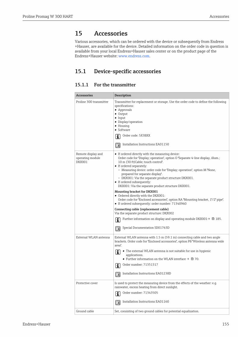
Proline Promag W 300 HART Accessories
Endress+Hauser 155
15 AccessoriesVarious accessories, which can be ordered with the device or subsequently from Endress+Hauser, are available for the device. Detailed information on the order code in question isavailable from your local Endress+Hauser sales center or on the product page of theEndress+Hauser website: www.endress.com.
15.1 Device-specific accessories
15.1.1 For the transmitter
Accessories Description
Proline 300 transmitter Transmitter for replacement or storage. Use the order code to define the followingspecifications:• Approvals• Output• Input• Display/operation• Housing• Software
Order code: 5X3BXX
Installation Instructions EA01150
Remote display andoperating moduleDKX001
• If ordered directly with the measuring device:Order code for "Display; operation", option O "Separate 4-line display, illum.;10 m (30 ft)Cable; touch control".
• If ordered separately:– Measuring device: order code for "Display; operation", option M "None,
prepared for separate display".– DKX001: Via the separate product structure DKX001.
• If ordered subsequently:DKX001: Via the separate product structure DKX001.
Mounting bracket for DKX001• Ordered directly with the DKX001:
Order code for "Enclosed accessories", option RA "Mounting bracket, 1"/2" pipe".• If ordered subsequently: order number: 71340960
Connecting cable (replacement cable)Via the separate product structure: DKX002
Further information on display and operating module DKX001→ 185.
Special Documentation SD01763D
External WLAN antenna External WLAN antenna with 1.5 m (59.1 in) connecting cable and two anglebrackets. Order code for "Enclosed accessories", option P8 "Wireless antenna widearea".
• The external WLAN antenna is not suitable for use in hygienicapplications.
• Further information on the WLAN interface → 70.
Order number: 71351317
Installation Instructions EA01238D
Protective cover Is used to protect the measuring device from the effects of the weather: e.g.rainwater, excess heating from direct sunlight.
Order number: 71343505
Installation Instructions EA01160
Ground cable Set, consisting of two ground cables for potential equalization.
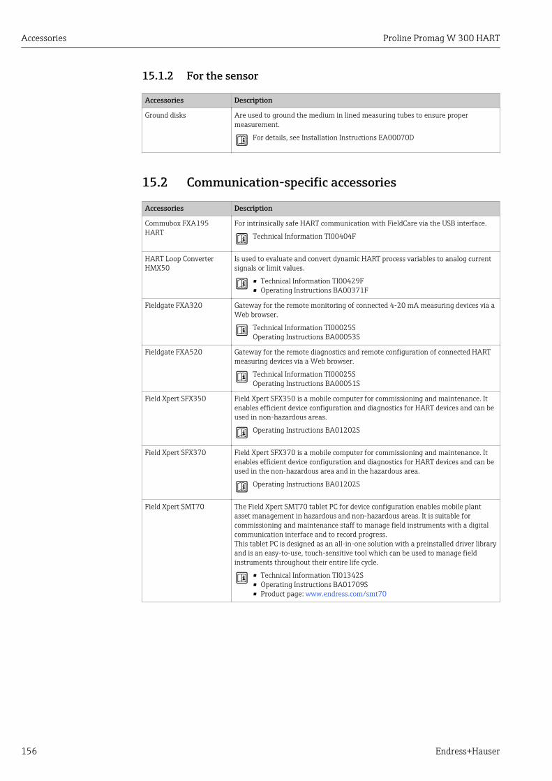
Accessories Proline Promag W 300 HART
156 Endress+Hauser
15.1.2 For the sensor
Accessories Description
Ground disks Are used to ground the medium in lined measuring tubes to ensure propermeasurement.
For details, see Installation Instructions EA00070D
15.2 Communication-specific accessories
Accessories Description
Commubox FXA195HART
For intrinsically safe HART communication with FieldCare via the USB interface.
Technical Information TI00404F
HART Loop ConverterHMX50
Is used to evaluate and convert dynamic HART process variables to analog currentsignals or limit values.
• Technical Information TI00429F• Operating Instructions BA00371F
Fieldgate FXA320 Gateway for the remote monitoring of connected 4-20 mA measuring devices via aWeb browser.
Technical Information TI00025SOperating Instructions BA00053S
Fieldgate FXA520 Gateway for the remote diagnostics and remote configuration of connected HARTmeasuring devices via a Web browser.
Technical Information TI00025SOperating Instructions BA00051S
Field Xpert SFX350 Field Xpert SFX350 is a mobile computer for commissioning and maintenance. Itenables efficient device configuration and diagnostics for HART devices and can beused in non-hazardous areas.
Operating Instructions BA01202S
Field Xpert SFX370 Field Xpert SFX370 is a mobile computer for commissioning and maintenance. Itenables efficient device configuration and diagnostics for HART devices and can beused in the non-hazardous area and in the hazardous area.
Operating Instructions BA01202S
Field Xpert SMT70 The Field Xpert SMT70 tablet PC for device configuration enables mobile plantasset management in hazardous and non-hazardous areas. It is suitable forcommissioning and maintenance staff to manage field instruments with a digitalcommunication interface and to record progress.This tablet PC is designed as an all-in-one solution with a preinstalled driver libraryand is an easy-to-use, touch-sensitive tool which can be used to manage fieldinstruments throughout their entire life cycle.
• Technical Information TI01342S• Operating Instructions BA01709S• Product page: www.endress.com/smt70

Proline Promag W 300 HART Accessories
Endress+Hauser 157
15.3 Service-specific accessories
Accessories Description
Applicator Software for selecting and sizing Endress+Hauser measuring devices:• Choice of measuring devices for industrial requirements• Calculation of all the necessary data for identifying the optimum flowmeter: e.g.
nominal diameter, pressure loss, flow velocity and accuracy.• Graphic illustration of the calculation results• Determination of the partial order code, administration, documentation and
access to all project-related data and parameters over the entire life cycle of aproject.
Applicator is available:• Via the Internet: https://portal.endress.com/webapp/applicator• As a downloadable DVD for local PC installation.
W@M W@M Life Cycle ManagementImproved productivity with information at your fingertips. Data relevant to a plantand its components is generated from the first stages of planning and during theasset’s complete life cycle.W@M Life Cycle Management is an open and flexible information platform withonline and on-site tools. Instant access for your staff to current, in-depth datashortens your plant’s engineering time, speeds up procurement processes andincreases plant uptime.Combined with the right services, W@M Life Cycle Management boostsproductivity in every phase. For more information, visitwww.endress.com/lifecyclemanagement
FieldCare FDT-based plant asset management tool from Endress+Hauser.It can configure all smart field units in your system and helps you manage them. Byusing the status information, it is also a simple but effective way of checking theirstatus and condition.
Operating Instructions BA00027S and BA00059S
DeviceCare Tool to connect and configure Endress+Hauser field devices.
Innovation brochure IN01047S
15.4 System components
Accessories Description
Memograph M graphicdata manager
The Memograph M graphic data manager provides information on all the relevantmeasured variables. Measured values are recorded correctly, limit values aremonitored and measuring points analyzed. The data are stored in the 256 MBinternal memory and also on a SD card or USB stick.
• Technical Information TI00133R• Operating Instructions BA00247R
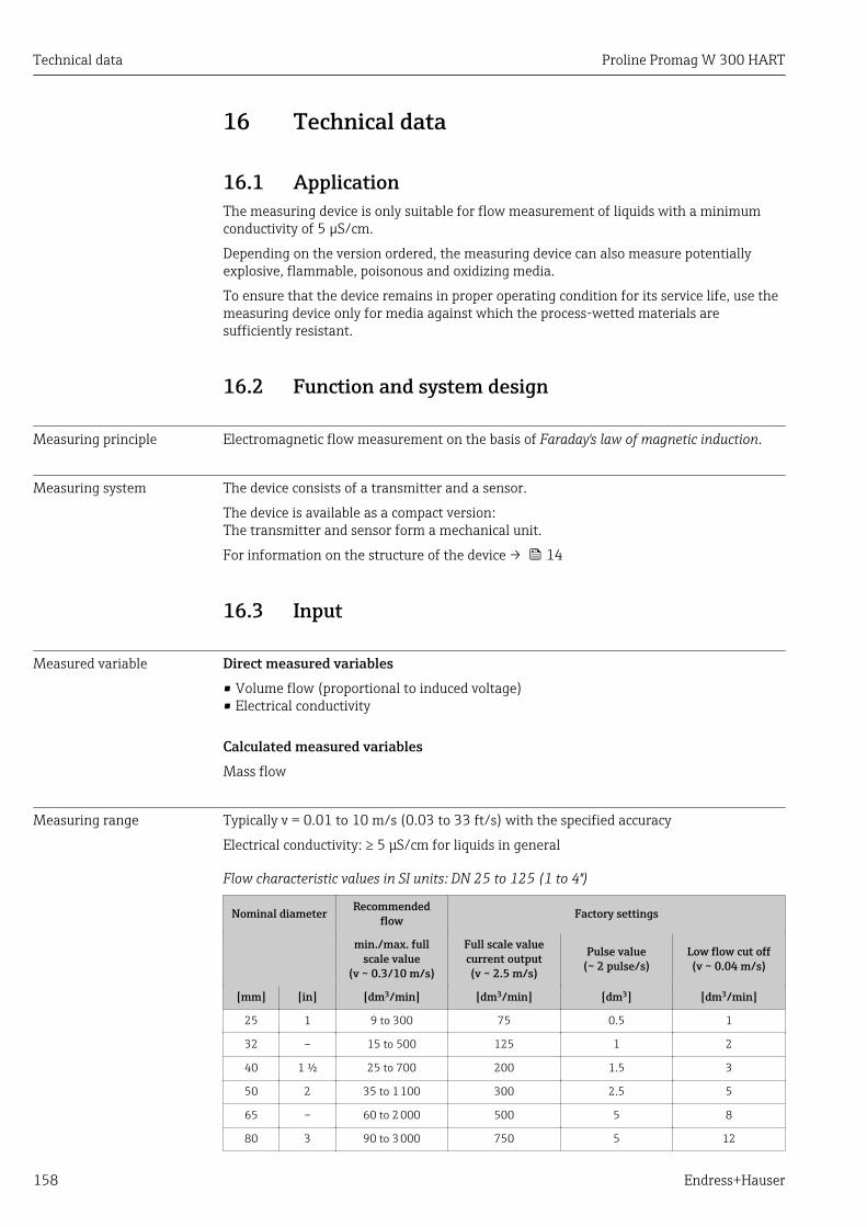
Technical data Proline Promag W 300 HART
158 Endress+Hauser
16 Technical data
16.1 ApplicationThe measuring device is only suitable for flow measurement of liquids with a minimumconductivity of 5 µS/cm.
Depending on the version ordered, the measuring device can also measure potentiallyexplosive, flammable, poisonous and oxidizing media.
To ensure that the device remains in proper operating condition for its service life, use themeasuring device only for media against which the process-wetted materials aresufficiently resistant.
16.2 Function and system design
Measuring principle Electromagnetic flow measurement on the basis of Faraday's law of magnetic induction.
Measuring system The device consists of a transmitter and a sensor.
The device is available as a compact version:The transmitter and sensor form a mechanical unit.
For information on the structure of the device → 14
16.3 Input
Measured variable Direct measured variables• Volume flow (proportional to induced voltage)• Electrical conductivity
Calculated measured variablesMass flow
Measuring range Typically v = 0.01 to 10 m/s (0.03 to 33 ft/s) with the specified accuracy
Electrical conductivity: ≥ 5 μS/cm for liquids in general
Flow characteristic values in SI units: DN 25 to 125 (1 to 4")
Nominal diameter Recommendedflow Factory settings
min./max. fullscale value
(v ~ 0.3/10 m/s)
Full scale valuecurrent output(v ~ 2.5 m/s)
Pulse value(~ 2 pulse/s)
Low flow cut off(v ~ 0.04 m/s)
[mm] [in] [dm3/min] [dm3/min] [dm3] [dm3/min]
25 1 9 to 300 75 0.5 1
32 – 15 to 500 125 1 2
40 1 ½ 25 to 700 200 1.5 3
50 2 35 to 1 100 300 2.5 5
65 – 60 to 2 000 500 5 8
80 3 90 to 3 000 750 5 12
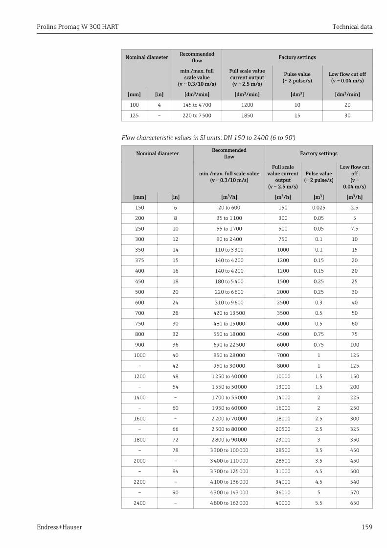
Proline Promag W 300 HART Technical data
Endress+Hauser 159
Nominal diameter Recommendedflow Factory settings
min./max. fullscale value
(v ~ 0.3/10 m/s)
Full scale valuecurrent output(v ~ 2.5 m/s)
Pulse value(~ 2 pulse/s)
Low flow cut off(v ~ 0.04 m/s)
[mm] [in] [dm3/min] [dm3/min] [dm3] [dm3/min]
100 4 145 to 4 700 1200 10 20
125 – 220 to 7 500 1850 15 30
Flow characteristic values in SI units: DN 150 to 2400 (6 to 90")
Nominal diameter Recommendedflow Factory settings
min./max. full scale value(v ~ 0.3/10 m/s)
Full scalevalue current
output(v ~ 2.5 m/s)
Pulse value(~ 2 pulse/s)
Low flow cutoff(v ~
0.04 m/s)
[mm] [in] [m3/h] [m3/h] [m3] [m3/h]
150 6 20 to 600 150 0.025 2.5
200 8 35 to 1 100 300 0.05 5
250 10 55 to 1 700 500 0.05 7.5
300 12 80 to 2 400 750 0.1 10
350 14 110 to 3 300 1000 0.1 15
375 15 140 to 4 200 1200 0.15 20
400 16 140 to 4 200 1200 0.15 20
450 18 180 to 5 400 1500 0.25 25
500 20 220 to 6 600 2000 0.25 30
600 24 310 to 9 600 2500 0.3 40
700 28 420 to 13 500 3500 0.5 50
750 30 480 to 15 000 4000 0.5 60
800 32 550 to 18 000 4500 0.75 75
900 36 690 to 22 500 6000 0.75 100
1000 40 850 to 28 000 7000 1 125
– 42 950 to 30 000 8000 1 125
1200 48 1 250 to 40 000 10000 1.5 150
– 54 1 550 to 50 000 13000 1.5 200
1400 – 1 700 to 55 000 14000 2 225
– 60 1 950 to 60 000 16000 2 250
1600 – 2 200 to 70 000 18000 2.5 300
– 66 2 500 to 80 000 20500 2.5 325
1800 72 2 800 to 90 000 23000 3 350
– 78 3 300 to 100 000 28500 3.5 450
2000 – 3 400 to 110 000 28500 3.5 450
– 84 3 700 to 125 000 31000 4.5 500
2200 – 4 100 to 136 000 34000 4.5 540
– 90 4 300 to 143 000 36000 5 570
2400 – 4 800 to 162 000 40000 5.5 650
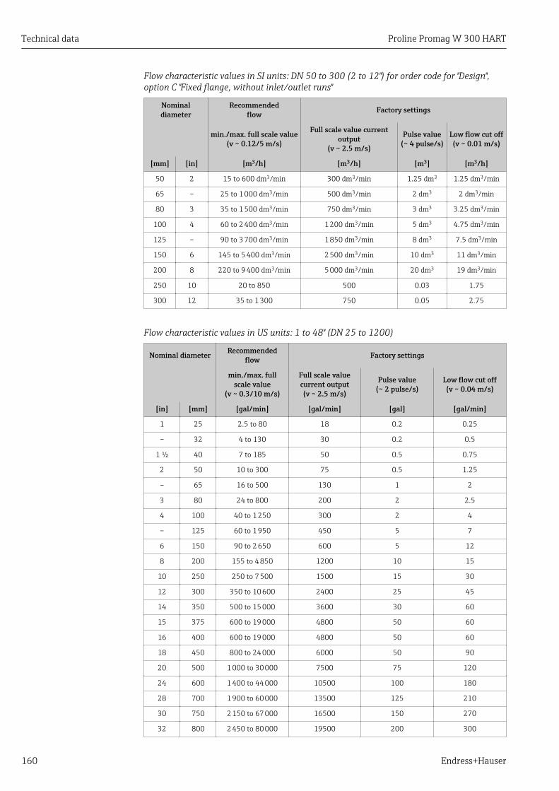
Technical data Proline Promag W 300 HART
160 Endress+Hauser
Flow characteristic values in SI units: DN 50 to 300 (2 to 12") for order code for "Design",option C "Fixed flange, without inlet/outlet runs"
Nominaldiameter
Recommendedflow Factory settings
min./max. full scale value(v ~ 0.12/5 m/s)
Full scale value currentoutput
(v ~ 2.5 m/s)
Pulse value(~ 4 pulse/s)
Low flow cut off(v ~ 0.01 m/s)
[mm] [in] [m3/h] [m3/h] [m3] [m3/h]
50 2 15 to 600 dm3/min 300 dm3/min 1.25 dm3 1.25 dm3/min
65 – 25 to 1 000 dm3/min 500 dm3/min 2 dm3 2 dm3/min
80 3 35 to 1 500 dm3/min 750 dm3/min 3 dm3 3.25 dm3/min
100 4 60 to 2 400 dm3/min 1 200 dm3/min 5 dm3 4.75 dm3/min
125 – 90 to 3 700 dm3/min 1 850 dm3/min 8 dm3 7.5 dm3/min
150 6 145 to 5 400 dm3/min 2 500 dm3/min 10 dm3 11 dm3/min
200 8 220 to 9 400 dm3/min 5 000 dm3/min 20 dm3 19 dm3/min
250 10 20 to 850 500 0.03 1.75
300 12 35 to 1 300 750 0.05 2.75
Flow characteristic values in US units: 1 to 48" (DN 25 to 1200)
Nominal diameter Recommendedflow Factory settings
min./max. fullscale value
(v ~ 0.3/10 m/s)
Full scale valuecurrent output(v ~ 2.5 m/s)
Pulse value(~ 2 pulse/s)
Low flow cut off(v ~ 0.04 m/s)
[in] [mm] [gal/min] [gal/min] [gal] [gal/min]
1 25 2.5 to 80 18 0.2 0.25
– 32 4 to 130 30 0.2 0.5
1 ½ 40 7 to 185 50 0.5 0.75
2 50 10 to 300 75 0.5 1.25
– 65 16 to 500 130 1 2
3 80 24 to 800 200 2 2.5
4 100 40 to 1 250 300 2 4
– 125 60 to 1 950 450 5 7
6 150 90 to 2 650 600 5 12
8 200 155 to 4 850 1200 10 15
10 250 250 to 7 500 1500 15 30
12 300 350 to 10 600 2400 25 45
14 350 500 to 15 000 3600 30 60
15 375 600 to 19 000 4800 50 60
16 400 600 to 19 000 4800 50 60
18 450 800 to 24 000 6000 50 90
20 500 1 000 to 30 000 7500 75 120
24 600 1 400 to 44 000 10500 100 180
28 700 1 900 to 60 000 13500 125 210
30 750 2 150 to 67 000 16500 150 270
32 800 2 450 to 80 000 19500 200 300
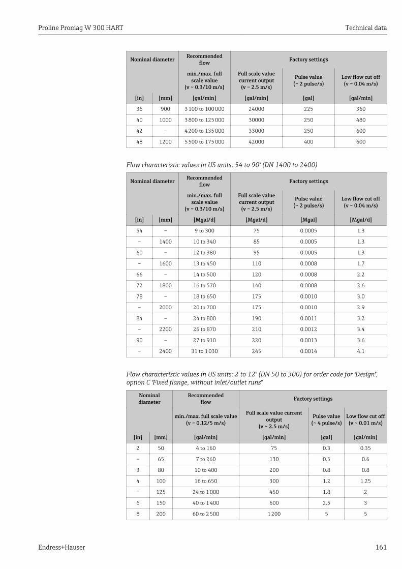
Proline Promag W 300 HART Technical data
Endress+Hauser 161
Nominal diameter Recommendedflow Factory settings
min./max. fullscale value
(v ~ 0.3/10 m/s)
Full scale valuecurrent output(v ~ 2.5 m/s)
Pulse value(~ 2 pulse/s)
Low flow cut off(v ~ 0.04 m/s)
[in] [mm] [gal/min] [gal/min] [gal] [gal/min]
36 900 3 100 to 100 000 24000 225 360
40 1000 3 800 to 125 000 30000 250 480
42 – 4 200 to 135 000 33000 250 600
48 1200 5 500 to 175 000 42000 400 600
Flow characteristic values in US units: 54 to 90" (DN 1400 to 2400)
Nominal diameter Recommendedflow Factory settings
min./max. fullscale value
(v ~ 0.3/10 m/s)
Full scale valuecurrent output(v ~ 2.5 m/s)
Pulse value(~ 2 pulse/s)
Low flow cut off(v ~ 0.04 m/s)
[in] [mm] [Mgal/d] [Mgal/d] [Mgal] [Mgal/d]
54 – 9 to 300 75 0.0005 1.3
– 1400 10 to 340 85 0.0005 1.3
60 – 12 to 380 95 0.0005 1.3
– 1600 13 to 450 110 0.0008 1.7
66 – 14 to 500 120 0.0008 2.2
72 1800 16 to 570 140 0.0008 2.6
78 – 18 to 650 175 0.0010 3.0
– 2000 20 to 700 175 0.0010 2.9
84 – 24 to 800 190 0.0011 3.2
– 2200 26 to 870 210 0.0012 3.4
90 – 27 to 910 220 0.0013 3.6
– 2400 31 to 1 030 245 0.0014 4.1
Flow characteristic values in US units: 2 to 12" (DN 50 to 300) for order code for "Design",option C "Fixed flange, without inlet/outlet runs"
Nominaldiameter
Recommendedflow Factory settings
min./max. full scale value(v ~ 0.12/5 m/s)
Full scale value currentoutput
(v ~ 2.5 m/s)
Pulse value(~ 4 pulse/s)
Low flow cut off(v ~ 0.01 m/s)
[in] [mm] [gal/min] [gal/min] [gal] [gal/min]
2 50 4 to 160 75 0.3 0.35
– 65 7 to 260 130 0.5 0.6
3 80 10 to 400 200 0.8 0.8
4 100 16 to 650 300 1.2 1.25
– 125 24 to 1 000 450 1.8 2
6 150 40 to 1 400 600 2.5 3
8 200 60 to 2 500 1 200 5 5
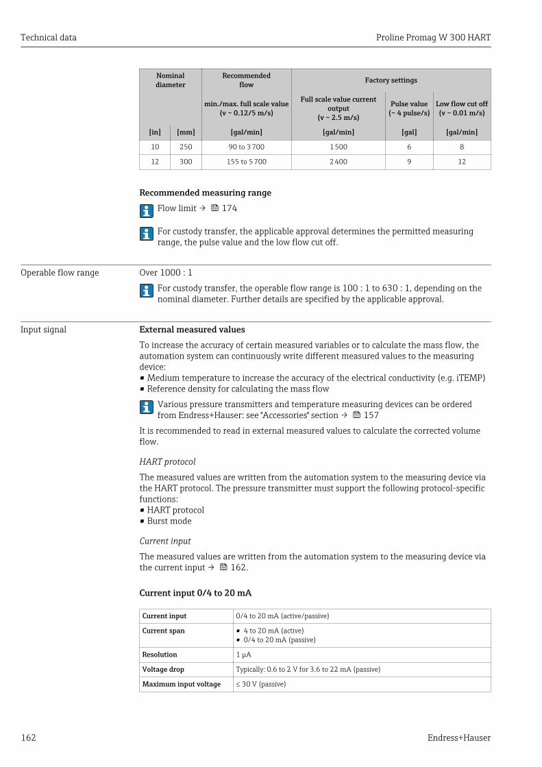
Technical data Proline Promag W 300 HART
162 Endress+Hauser
Nominaldiameter
Recommendedflow Factory settings
min./max. full scale value(v ~ 0.12/5 m/s)
Full scale value currentoutput
(v ~ 2.5 m/s)
Pulse value(~ 4 pulse/s)
Low flow cut off(v ~ 0.01 m/s)
[in] [mm] [gal/min] [gal/min] [gal] [gal/min]
10 250 90 to 3 700 1 500 6 8
12 300 155 to 5 700 2 400 9 12
Recommended measuring rangeFlow limit → 174
For custody transfer, the applicable approval determines the permitted measuringrange, the pulse value and the low flow cut off.
Operable flow range Over 1000 : 1
For custody transfer, the operable flow range is 100 : 1 to 630 : 1, depending on thenominal diameter. Further details are specified by the applicable approval.
Input signal External measured valuesTo increase the accuracy of certain measured variables or to calculate the mass flow, theautomation system can continuously write different measured values to the measuringdevice:• Medium temperature to increase the accuracy of the electrical conductivity (e.g. iTEMP)• Reference density for calculating the mass flow
Various pressure transmitters and temperature measuring devices can be orderedfrom Endress+Hauser: see "Accessories" section → 157
It is recommended to read in external measured values to calculate the corrected volumeflow.
HART protocol
The measured values are written from the automation system to the measuring device viathe HART protocol. The pressure transmitter must support the following protocol-specificfunctions:• HART protocol• Burst mode
Current input
The measured values are written from the automation system to the measuring device viathe current input → 162.
Current input 0/4 to 20 mA
Current input 0/4 to 20 mA (active/passive)
Current span • 4 to 20 mA (active)• 0/4 to 20 mA (passive)
Resolution 1 µA
Voltage drop Typically: 0.6 to 2 V for 3.6 to 22 mA (passive)
Maximum input voltage ≤ 30 V (passive)
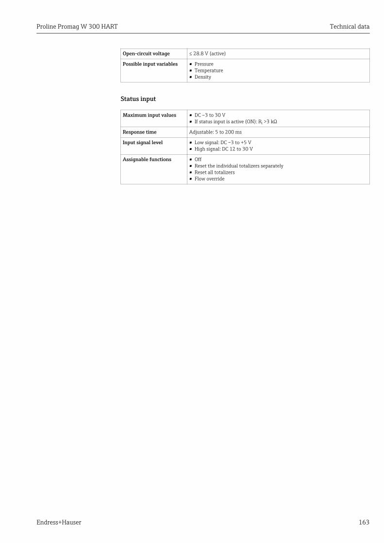
Proline Promag W 300 HART Technical data
Endress+Hauser 163
Open-circuit voltage ≤ 28.8 V (active)
Possible input variables • Pressure• Temperature• Density
Status input
Maximum input values • DC –3 to 30 V• If status input is active (ON): Ri >3 kΩ
Response time Adjustable: 5 to 200 ms
Input signal level • Low signal: DC –3 to +5 V• High signal: DC 12 to 30 V
Assignable functions • Off• Reset the individual totalizers separately• Reset all totalizers• Flow override
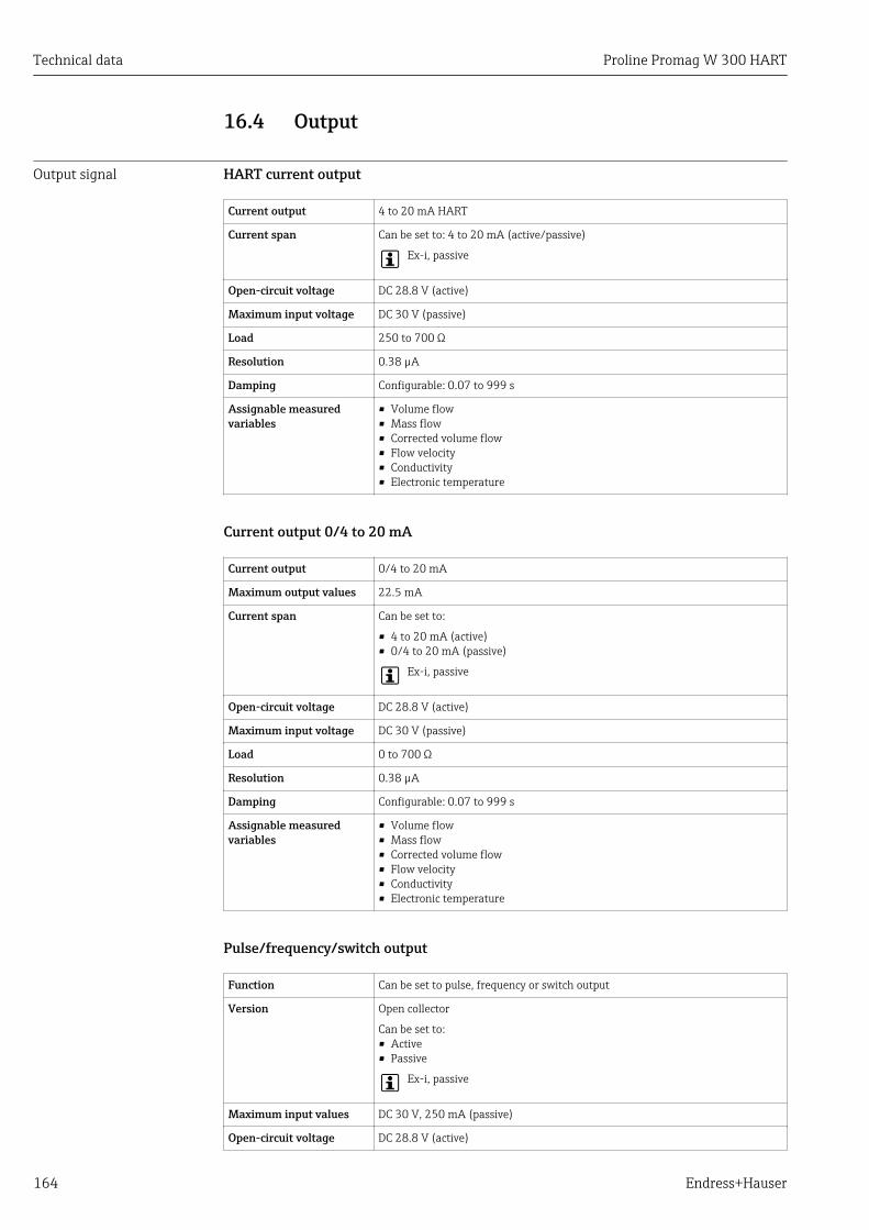
Technical data Proline Promag W 300 HART
164 Endress+Hauser
16.4 Output
Output signal HART current output
Current output 4 to 20 mA HART
Current span Can be set to: 4 to 20 mA (active/passive)
Ex-i, passive
Open-circuit voltage DC 28.8 V (active)
Maximum input voltage DC 30 V (passive)
Load 250 to 700 Ω
Resolution 0.38 µA
Damping Configurable: 0.07 to 999 s
Assignable measuredvariables
• Volume flow• Mass flow• Corrected volume flow• Flow velocity• Conductivity• Electronic temperature
Current output 0/4 to 20 mA
Current output 0/4 to 20 mA
Maximum output values 22.5 mA
Current span Can be set to:
• 4 to 20 mA (active)• 0/4 to 20 mA (passive)
Ex-i, passive
Open-circuit voltage DC 28.8 V (active)
Maximum input voltage DC 30 V (passive)
Load 0 to 700 Ω
Resolution 0.38 µA
Damping Configurable: 0.07 to 999 s
Assignable measuredvariables
• Volume flow• Mass flow• Corrected volume flow• Flow velocity• Conductivity• Electronic temperature
Pulse/frequency/switch output
Function Can be set to pulse, frequency or switch output
Version Open collector
Can be set to:• Active• Passive
Ex-i, passive
Maximum input values DC 30 V, 250 mA (passive)
Open-circuit voltage DC 28.8 V (active)
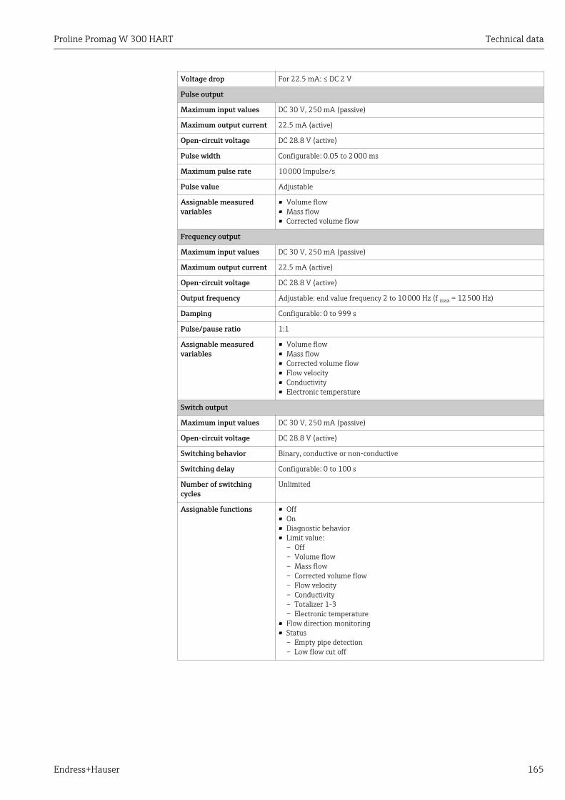
Proline Promag W 300 HART Technical data
Endress+Hauser 165
Voltage drop For 22.5 mA: ≤ DC 2 V
Pulse output
Maximum input values DC 30 V, 250 mA (passive)
Maximum output current 22.5 mA (active)
Open-circuit voltage DC 28.8 V (active)
Pulse width Configurable: 0.05 to 2 000 ms
Maximum pulse rate 10 000 Impulse/s
Pulse value Adjustable
Assignable measuredvariables
• Volume flow• Mass flow• Corrected volume flow
Frequency output
Maximum input values DC 30 V, 250 mA (passive)
Maximum output current 22.5 mA (active)
Open-circuit voltage DC 28.8 V (active)
Output frequency Adjustable: end value frequency 2 to 10 000 Hz (f max = 12 500 Hz)
Damping Configurable: 0 to 999 s
Pulse/pause ratio 1:1
Assignable measuredvariables
• Volume flow• Mass flow• Corrected volume flow• Flow velocity• Conductivity• Electronic temperature
Switch output
Maximum input values DC 30 V, 250 mA (passive)
Open-circuit voltage DC 28.8 V (active)
Switching behavior Binary, conductive or non-conductive
Switching delay Configurable: 0 to 100 s
Number of switchingcycles
Unlimited
Assignable functions • Off• On• Diagnostic behavior• Limit value:
– Off– Volume flow– Mass flow– Corrected volume flow– Flow velocity– Conductivity– Totalizer 1-3– Electronic temperature
• Flow direction monitoring• Status
– Empty pipe detection– Low flow cut off

Technical data Proline Promag W 300 HART
166 Endress+Hauser
Double pulse output
Function Double pulse
Version Open collector
Can be set to:• Active• Passive
Maximum input values DC 30 V, 250 mA (passive)
Open-circuit voltage DC 28.8 V (active)
Voltage drop For 22.5 mA: ≤ DC 2 V
Output frequency Configurable: 0 to 1 000 Hz
Damping Configurable: 0 to 999 s
Pulse/pause ratio 1:1
Assignable measuredvariables
• Volume flow• Mass flow• Corrected volume flow• Flow velocity• Conductivity• Electronic temperature
Relay output
Function Switch output
Version Relay output, galvanically isolated
Switching behavior Can be set to:• NO (normally open), factory setting• NC (normally closed)
Maximum switchingcapacity (passive)
• DC 30 V, 0.1 A• AC 30 V, 0.5 A
Assignable functions • Off• On• Diagnostic behavior• Limit value:
– Off– Volume flow– Mass flow– Corrected volume flow– Flow velocity– Conductivity– Totalizer 1-3– Electronic temperature
• Flow direction monitoring• Status
– Empty pipe detection– Low flow cut off
User configurable input/outputOne specific input or output is assigned to a user-configurable input/output (configurableI/O) during device commissioning.
The following inputs and outputs are available for assignment:• Choice of current output: 4 to 20 mA (active), 0/4 to 20 mA (passive)• Pulse/frequency/switch output• Choice of current input: 4 to 20 mA (active), 0/4 to 20 mA (passive)• Status input
The technical values correspond to those of the inputs and outputs described in thissection.
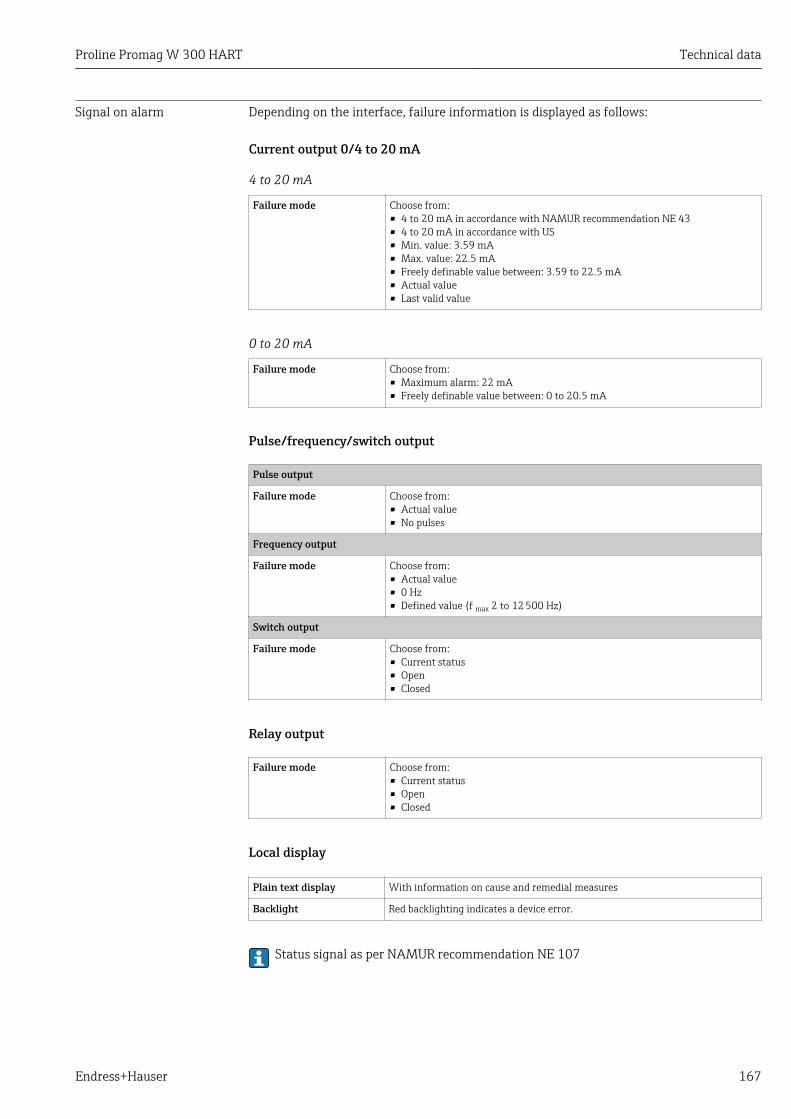
Proline Promag W 300 HART Technical data
Endress+Hauser 167
Signal on alarm Depending on the interface, failure information is displayed as follows:
Current output 0/4 to 20 mA
4 to 20 mA
Failure mode Choose from:• 4 to 20 mA in accordance with NAMUR recommendation NE 43• 4 to 20 mA in accordance with US• Min. value: 3.59 mA• Max. value: 22.5 mA• Freely definable value between: 3.59 to 22.5 mA• Actual value• Last valid value
0 to 20 mA
Failure mode Choose from:• Maximum alarm: 22 mA• Freely definable value between: 0 to 20.5 mA
Pulse/frequency/switch output
Pulse output
Failure mode Choose from:• Actual value• No pulses
Frequency output
Failure mode Choose from:• Actual value• 0 Hz• Defined value (f max 2 to 12 500 Hz)
Switch output
Failure mode Choose from:• Current status• Open• Closed
Relay output
Failure mode Choose from:• Current status• Open• Closed
Local display
Plain text display With information on cause and remedial measures
Backlight Red backlighting indicates a device error.
Status signal as per NAMUR recommendation NE 107
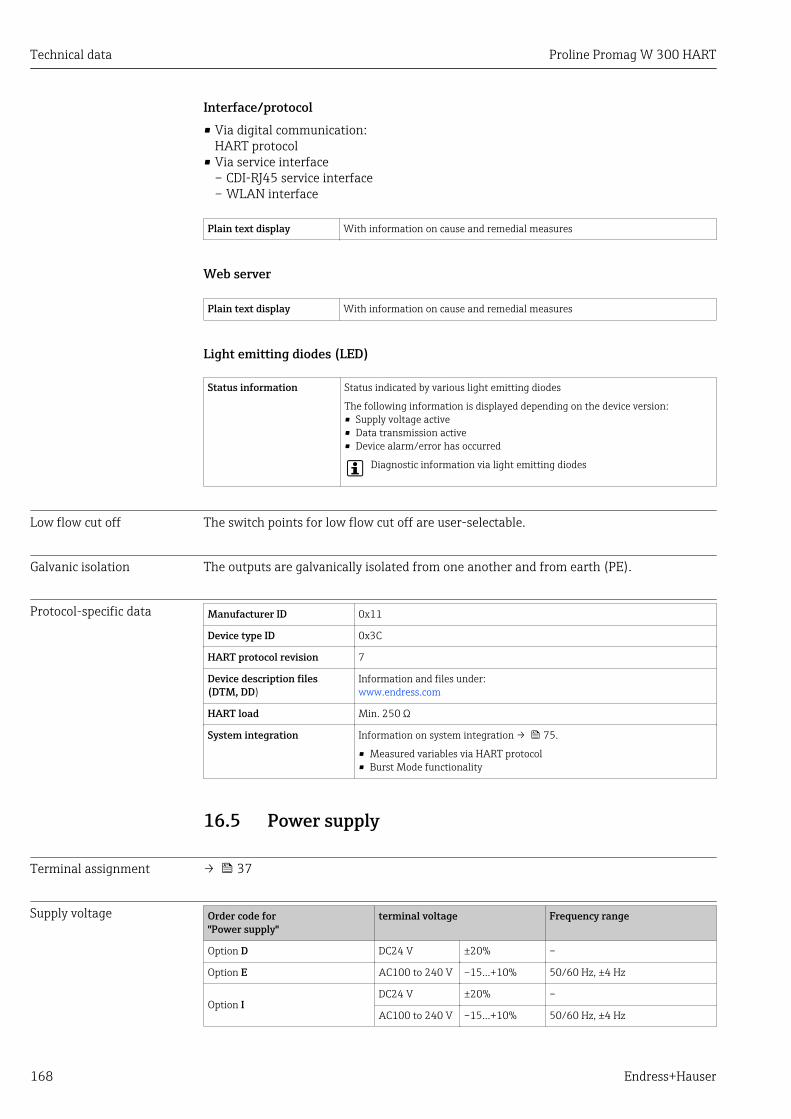
Technical data Proline Promag W 300 HART
168 Endress+Hauser
Interface/protocol• Via digital communication:
HART protocol• Via service interface
– CDI-RJ45 service interface– WLAN interface
Plain text display With information on cause and remedial measures
Web server
Plain text display With information on cause and remedial measures
Light emitting diodes (LED)
Status information Status indicated by various light emitting diodes
The following information is displayed depending on the device version:• Supply voltage active• Data transmission active• Device alarm/error has occurred
Diagnostic information via light emitting diodes
Low flow cut off The switch points for low flow cut off are user-selectable.
Galvanic isolation The outputs are galvanically isolated from one another and from earth (PE).
Protocol-specific data Manufacturer ID 0x11
Device type ID 0x3C
HART protocol revision 7
Device description files(DTM, DD)
Information and files under:www.endress.com
HART load Min. 250 Ω
System integration Information on system integration → 75.
• Measured variables via HART protocol• Burst Mode functionality
16.5 Power supply
Terminal assignment → 37
Supply voltage Order code for"Power supply"
terminal voltage Frequency range
Option D DC24 V ±20% –
Option E AC100 to 240 V –15…+10% 50/60 Hz, ±4 Hz
Option IDC24 V ±20% –
AC100 to 240 V –15…+10% 50/60 Hz, ±4 Hz

Proline Promag W 300 HART Technical data
Endress+Hauser 169
Power consumption TransmitterMax. 10 W (active power)
switch-on current Max. 36 A (<5 ms) as per NAMUR Recommendation NE 21
Current consumption Transmitter• Max. 400 mA (24 V)• Max. 200 mA (110 V, 50/60 Hz; 230 V, 50/60 Hz)
Power supply failure • Totalizers stop at the last value measured.• Depending on the device version, the configuration is retained in the device memoryor in
the pluggable data memory (HistoROM DAT).• Error messages (incl. total operated hours) are stored.
Electrical connection → 37
Potential equalization → 40
terminals Spring-loaded terminals: Suitable for strands and strands with ferrules.Conductor cross-section 0.2 to 2.5 mm2 (24 to 12 AWG).
Cable entries • Cable gland: M20 × 1.5 with cable 6 to 12 mm (0.24 to 0.47 in)• Thread for cable entry:
– NPT ½"– G ½"– M20
Cable specification → 34
16.6 Performance characteristics
Reference operatingconditions
• Error limits following DIN EN 29104, in future ISO 20456• Water, typically: +15 to +45 °C (+59 to +113 °F); 0.5 to 7 bar (73 to 101 psi)• Data as indicated in the calibration protocol• Accuracy based on accredited calibration rigs according to ISO 17025
Maximum measured error Error limits under reference operating conditionso.r. = of reading
Volume flow• ±0.5 % o.r. ± 1 mm/s (0.04 in/s)• Optional: ±0.2 % o.r. ± 2 mm/s (0.08 in/s)
Fluctuations in the supply voltage do not have any effect within the specified range.
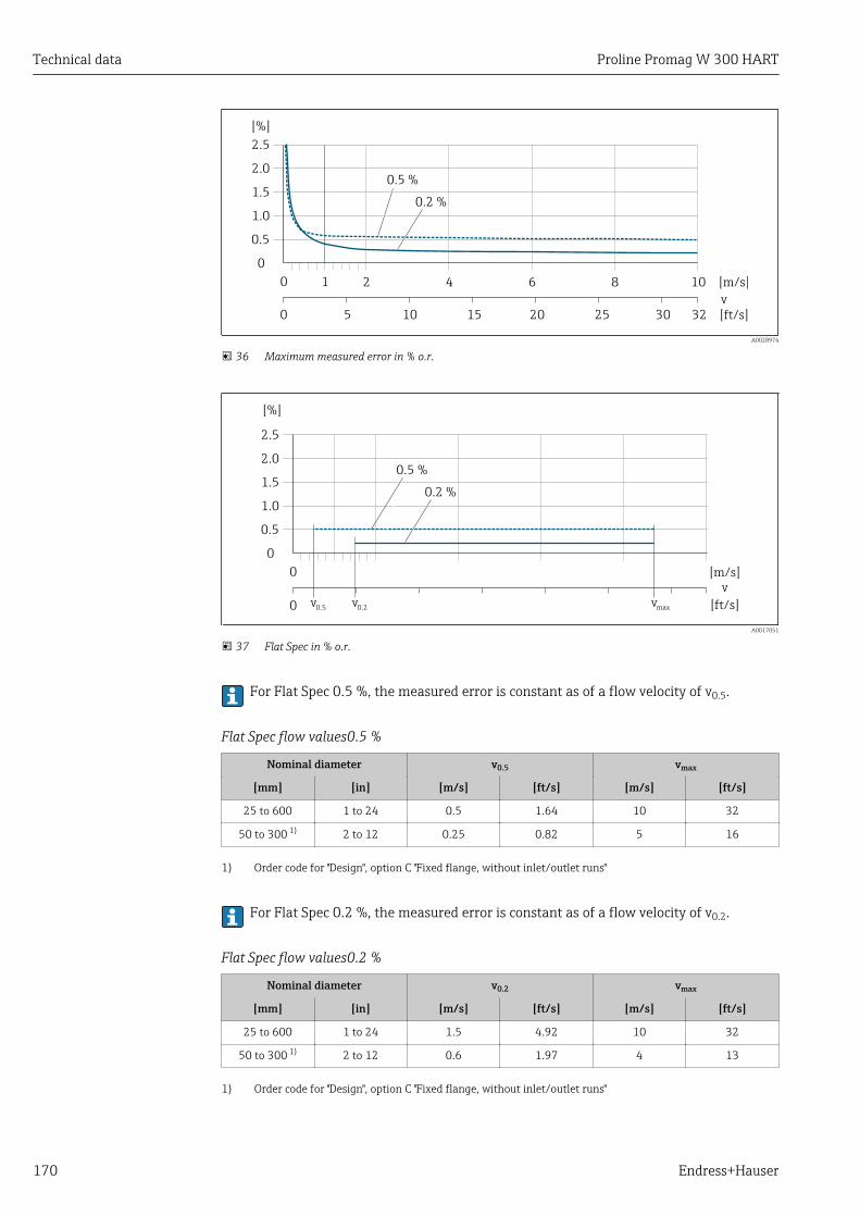
Technical data Proline Promag W 300 HART
170 Endress+Hauser
2.5
[%]
2.0
1.5
1.0
0.5
0
0.2 %
0.5 %
0 1 2 4 6 8 10 [m/s]
v
5 10 15 20 25 30 32 [ft/s]0
A0028974
36 Maximum measured error in % o.r.
2.5
[%]
2.0
1.5
1.0
0.5
0
0.2 %
0.5 %
0 [m/s]v
[ft/s]v0.2v0.50 vmax
A0017051
37 Flat Spec in % o.r.
For Flat Spec 0.5 %, the measured error is constant as of a flow velocity of v0.5.
Flat Spec flow values0.5 %
Nominal diameter v0.5 vmax
[mm] [in] [m/s] [ft/s] [m/s] [ft/s]
25 to 600 1 to 24 0.5 1.64 10 32
50 to 300 1) 2 to 12 0.25 0.82 5 16
1) Order code for "Design", option C "Fixed flange, without inlet/outlet runs"
For Flat Spec 0.2 %, the measured error is constant as of a flow velocity of v0.2.
Flat Spec flow values0.2 %
Nominal diameter v0.2 vmax
[mm] [in] [m/s] [ft/s] [m/s] [ft/s]
25 to 600 1 to 24 1.5 4.92 10 32
50 to 300 1) 2 to 12 0.6 1.97 4 13
1) Order code for "Design", option C "Fixed flange, without inlet/outlet runs"

Proline Promag W 300 HART Technical data
Endress+Hauser 171
Electrical conductivityMax. measured error not specified.
Accuracy of outputsThe outputs have the following base accuracy specifications.
Current output
Accuracy ±5 µA
Pulse/frequency output
o.r. = of reading
Accuracy Max. ±50 ppm o.r. (over the entire ambient temperature range)
Repeatability o.r. = of reading
Volume flowMax. ±0.1 % o.r. ± 0.5 mm/s (0.02 in/s)
Electrical conductivityMax. ±5 % o.r.
Influence of ambienttemperature
Current output
Temperature coefficient Max. 1 μA/°C
Pulse/frequency output
Temperature coefficient No additional effect. Included in accuracy.
16.7 Installation"Mounting requirements" → 20
16.8 Environment
Ambient temperaturerange
→ 23
Storage temperature The storage temperature corresponds to the operating temperature range of thetransmitter and the sensor → 23.
• Protect the measuring device against direct sunlight during storage in order to avoidunacceptably high surface temperatures.
• Select a storage location where moisture cannot collect in the measuring device asfungus or bacteria infestation can damage the liner.
• If protection caps or protective covers are mounted these should never be removedbefore installing the measuring device.

Technical data Proline Promag W 300 HART
172 Endress+Hauser
Degree of protection Measuring device• As standard: IP66/67, type 4X enclosure• When housing is open: IP20, type 1 enclosure• Display module: IP20, type 1 enclosure
External WLAN antennaIP67
Vibration resistance • Oscillation, sinusoidal, following IEC 60068-2-6– 2 to 8.4 Hz, 3.5 mm peak– 8.4 to 2 000 Hz, 1 g peak
• Oscillation, broadband noise following IEC 60068-2-64– 10 to 200 Hz, 0.003 g2/Hz– 200 to 2 000 Hz, 0.001 g2/Hz– Total: 1.54 g rms
Shock resistance Shock, half-sine according to IEC 60068-2-276 ms 50 g
Shock resistance Shock due to rough handling following IEC 60068-2-31
Mechanical load • Protect the transmitter housing against mechanical effects, such as shock or impact; theuse of the remote version is sometimes preferable.
• Never use the transmitter housing as a ladder or climbing aid.
Electromagneticcompatibility (EMC)
As per IEC/EN 61326 and NAMUR Recommendation 21 (NE 21)
Details are provided in the Declaration of Conformity.
16.9 Process
Medium temperature range • 0 to +80 °C (+32 to +176 °F) for hard rubber, DN 50 to 2400 (2 to 90")• –20 to +50 °C (–4 to +122 °F) for polyurethane, DN 25 to 1200 (1 to 48")• –20 to +90 °C (–4 to +194 °F) for PTFE, DN 25 to 300 (1 to 12")
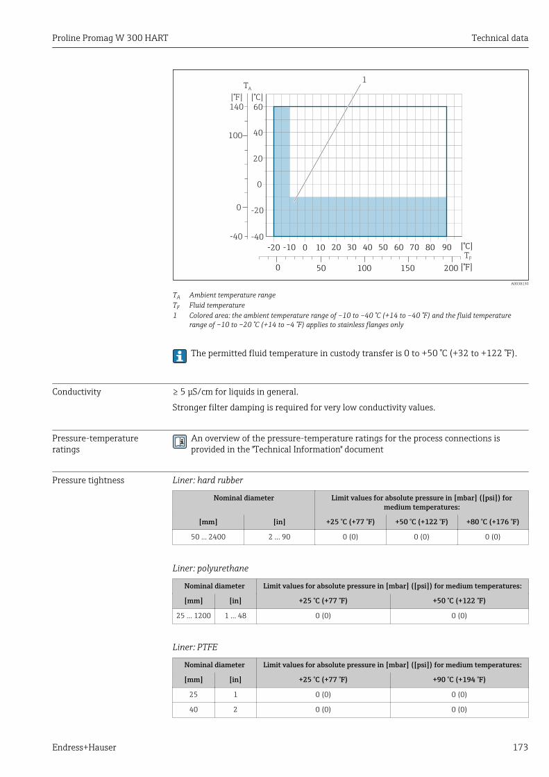
Proline Promag W 300 HART Technical data
Endress+Hauser 173
0
0
20
40100
60140
[°F] [°C]
-20
-40-40
TA
TF
1
-20 -10 0 10 20 30 40 50 60 70 80 90
0 100 200
[°C]
[° ]F50 150
A0038130
TA Ambient temperature rangeTF Fluid temperature1 Colored area: the ambient temperature range of –10 to –40 °C (+14 to –40 °F) and the fluid temperature
range of –10 to –20 °C (+14 to –4 °F) applies to stainless flanges only
The permitted fluid temperature in custody transfer is 0 to +50 °C (+32 to +122 °F).
Conductivity ≥ 5 μS/cm for liquids in general.
Stronger filter damping is required for very low conductivity values.
Pressure-temperatureratings
An overview of the pressure-temperature ratings for the process connections isprovided in the "Technical Information" document
Pressure tightness Liner: hard rubber
Nominal diameter Limit values for absolute pressure in [mbar] ([psi]) formedium temperatures:
[mm] [in] +25 °C (+77 °F) +50 °C (+122 °F) +80 °C (+176 °F)
50 … 2400 2 … 90 0 (0) 0 (0) 0 (0)
Liner: polyurethane
Nominal diameter Limit values for absolute pressure in [mbar] ([psi]) for medium temperatures:
[mm] [in] +25 °C (+77 °F) +50 °C (+122 °F)
25 … 1200 1 … 48 0 (0) 0 (0)
Liner: PTFE
Nominal diameter Limit values for absolute pressure in [mbar] ([psi]) for medium temperatures:
[mm] [in] +25 °C (+77 °F) +90 °C (+194 °F)
25 1 0 (0) 0 (0)
40 2 0 (0) 0 (0)
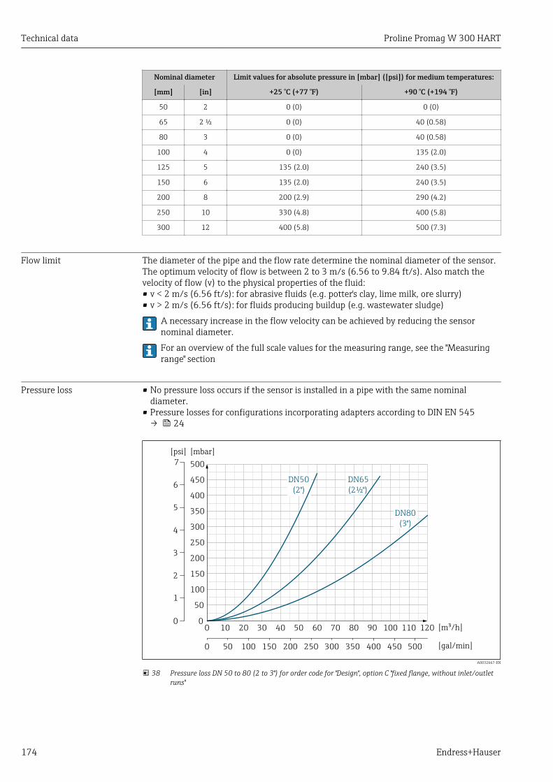
Technical data Proline Promag W 300 HART
174 Endress+Hauser
Nominal diameter Limit values for absolute pressure in [mbar] ([psi]) for medium temperatures:
[mm] [in] +25 °C (+77 °F) +90 °C (+194 °F)
50 2 0 (0) 0 (0)
65 2 ½ 0 (0) 40 (0.58)
80 3 0 (0) 40 (0.58)
100 4 0 (0) 135 (2.0)
125 5 135 (2.0) 240 (3.5)
150 6 135 (2.0) 240 (3.5)
200 8 200 (2.9) 290 (4.2)
250 10 330 (4.8) 400 (5.8)
300 12 400 (5.8) 500 (7.3)
Flow limit The diameter of the pipe and the flow rate determine the nominal diameter of the sensor.The optimum velocity of flow is between 2 to 3 m/s (6.56 to 9.84 ft/s). Also match thevelocity of flow (v) to the physical properties of the fluid:• v < 2 m/s (6.56 ft/s): for abrasive fluids (e.g. potter's clay, lime milk, ore slurry)• v > 2 m/s (6.56 ft/s): for fluids producing buildup (e.g. wastewater sludge)
A necessary increase in the flow velocity can be achieved by reducing the sensornominal diameter.
For an overview of the full scale values for the measuring range, see the "Measuringrange" section
Pressure loss • No pressure loss occurs if the sensor is installed in a pipe with the same nominaldiameter.
• Pressure losses for configurations incorporating adapters according to DIN EN 545→ 24
DN80(3")
DN65(2½")
DN50(2")
500
450
400
350
300
250
200
150
100
50
00 10 20 30 40 50 60 70 80 90 100 110 120
[mbar]
[m /h]³
0 100 200 300 400 50050 150 250 350 450 [gal/min]
7[psi]
0
1
2
3
4
5
6
A0032667-EN
38 Pressure loss DN 50 to 80 (2 to 3") for order code for "Design", option C "fixed flange, without inlet/outletruns"
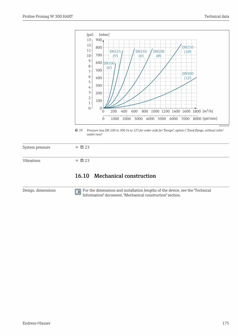
Proline Promag W 300 HART Technical data
Endress+Hauser 175
DN300(12")
DN100(4")
DN250(10")DN200
(8")DN150
(6")DN125
(5")
[mbar]
900
800
700
600
500
400
300
200
100
00 200 400 600 800 1000 1200 1400 1600 1800 [m /h]³
0
13
12
11
10
9
8
7
6
5
4
3
2
1
[psi]
0 1000 2000 3000 4000 5000 6000 7000 8000 [gal/min]
A0032668-EN
39 Pressure loss DN 100 to 300 (4 to 12") for order code for "Design", option C "fixed flange, without inlet/outlet runs"
System pressure → 23
Vibrations → 23
16.10 Mechanical construction
Design, dimensions For the dimensions and installation lengths of the device, see the "TechnicalInformation" document, "Mechanical construction" section.

Technical data Proline Promag W 300 HART
176 Endress+Hauser
Weight All values (weight exclusive of packaging material) refer to devices with flanges of thestandard pressure rating.The weight may be lower than indicated depending on the pressure rating and design.Weight specifications including transmitter as per order code for "Housing", option A"Aluminum, coated".
Different values due to different transmitter versions:Transmitter version for the hazardous area(Order code for "Housing", option A "Aluminum, coated"; Ex d): +2 kg (+4.4 lbs)
Weight in SI units
Order code for "Design", options C, D, EDN 25 to 400, DN 1" to 16"
Nominal diameter Reference values
EN (DIN), AS, JIS ASME (Class 150)
[mm] [in] Pressure rating [kg] [kg]
25 1 PN 40 10 5
32 – PN 40 11 –
40 1 ½ PN 40 12 7
50 2 PN 40 13 9
65 – PN 16 13 –
80 3 PN 16 15 14
100 4 PN 16 18 19
125 – PN 16 25 –
150 6 PN 16 31 33
200 8 PN 10 52 52
250 10 PN 10 81 90
300 12 PN 10 95 129
350 14 PN 6 106 172
375 15 PN 6 121 –
400 16 PN 6 121 203
Order code for "Design", options F≥ DN 450 (18")
Nominaldiameter
Reference values
EN (DIN) (PN16) AS (PN 16)ASME (Class 150), AWWA
(Class D)
[mm] [in] [kg] [kg] [kg]
450 18 142 138 191
500 20 182 186 228
600 24 227 266 302
700 28 291 369 266
– 30 – 447 318
800 32 353 524 383
900 36 444 704 470
1000 40 566 785 587
– 42 – – 670
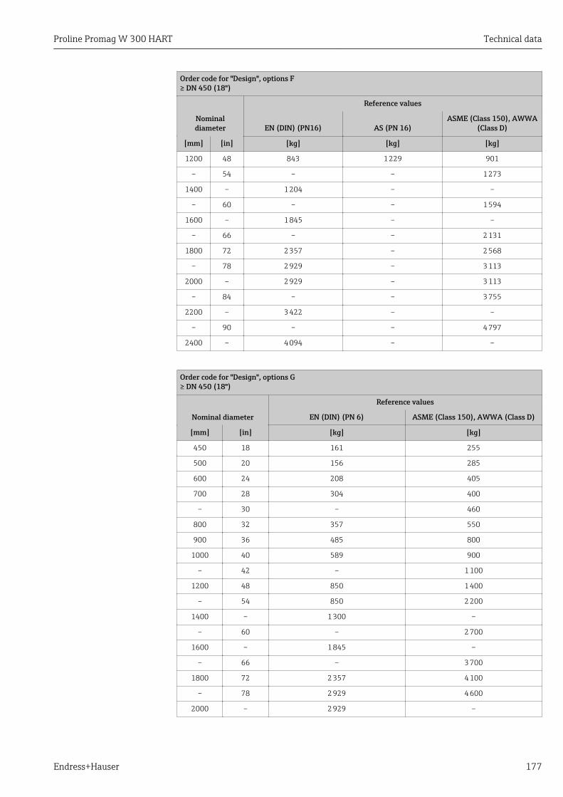
Proline Promag W 300 HART Technical data
Endress+Hauser 177
Order code for "Design", options F≥ DN 450 (18")
Nominaldiameter
Reference values
EN (DIN) (PN16) AS (PN 16)ASME (Class 150), AWWA
(Class D)
[mm] [in] [kg] [kg] [kg]
1200 48 843 1 229 901
– 54 – – 1 273
1400 – 1 204 – –
– 60 – – 1 594
1600 – 1 845 – –
– 66 – – 2 131
1800 72 2 357 – 2 568
– 78 2 929 – 3 113
2000 – 2 929 – 3 113
– 84 – – 3 755
2200 – 3 422 – –
– 90 – – 4 797
2400 – 4 094 – –
Order code for "Design", options G≥ DN 450 (18")
Nominal diameter
Reference values
EN (DIN) (PN 6) ASME (Class 150), AWWA (Class D)
[mm] [in] [kg] [kg]
450 18 161 255
500 20 156 285
600 24 208 405
700 28 304 400
– 30 – 460
800 32 357 550
900 36 485 800
1000 40 589 900
– 42 – 1 100
1200 48 850 1 400
– 54 850 2 200
1400 – 1 300 –
– 60 – 2 700
1600 – 1 845 –
– 66 – 3 700
1800 72 2 357 4 100
– 78 2 929 4 600
2000 – 2 929 –
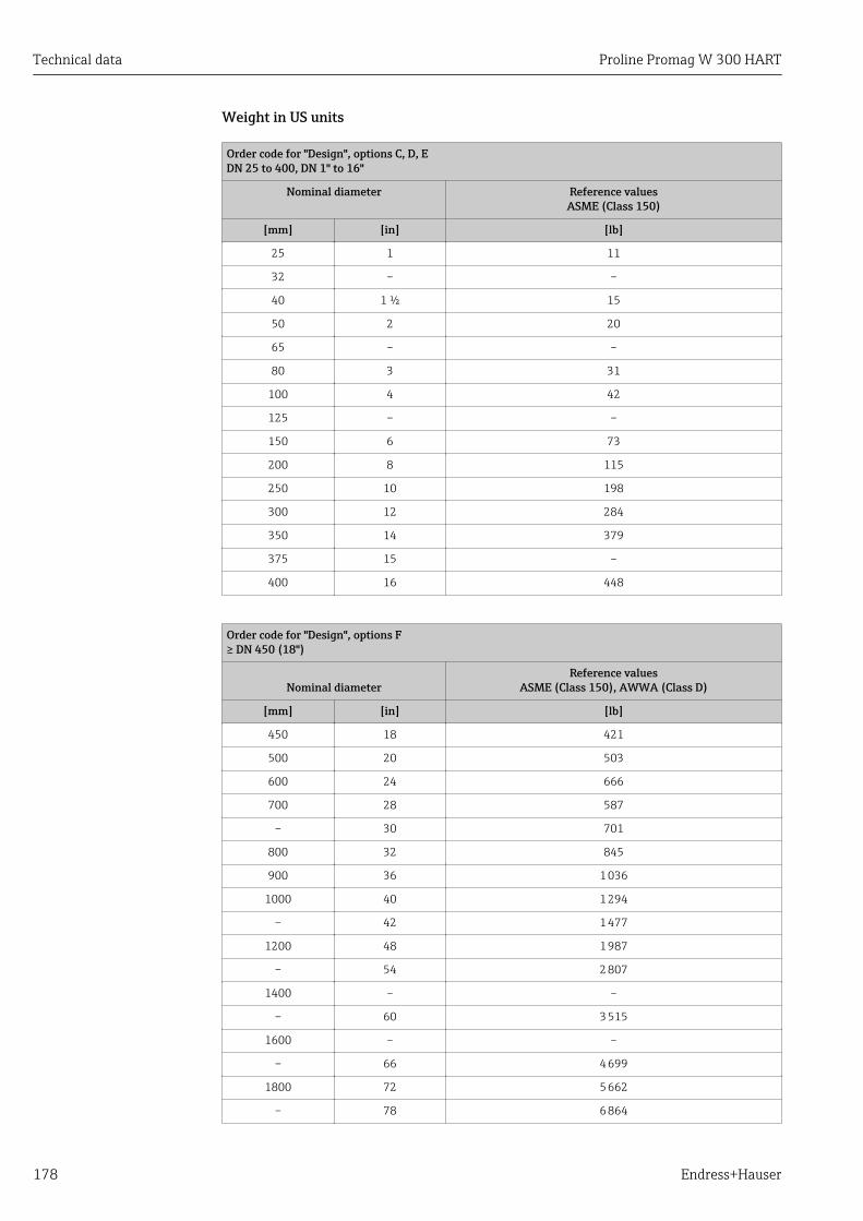
Technical data Proline Promag W 300 HART
178 Endress+Hauser
Weight in US units
Order code for "Design", options C, D, EDN 25 to 400, DN 1" to 16"
Nominal diameter Reference valuesASME (Class 150)
[mm] [in] [lb]
25 1 11
32 – –
40 1 ½ 15
50 2 20
65 – –
80 3 31
100 4 42
125 – –
150 6 73
200 8 115
250 10 198
300 12 284
350 14 379
375 15 –
400 16 448
Order code for "Design", options F≥ DN 450 (18")
Nominal diameterReference values
ASME (Class 150), AWWA (Class D)
[mm] [in] [lb]
450 18 421
500 20 503
600 24 666
700 28 587
– 30 701
800 32 845
900 36 1 036
1000 40 1 294
– 42 1 477
1200 48 1 987
– 54 2 807
1400 – –
– 60 3 515
1600 – –
– 66 4 699
1800 72 5 662
– 78 6 864

Proline Promag W 300 HART Technical data
Endress+Hauser 179
Order code for "Design", options F≥ DN 450 (18")
Nominal diameterReference values
ASME (Class 150), AWWA (Class D)
[mm] [in] [lb]
2000 – 6 864
– 84 8 280
2200 – –
– 90 10 577
2400 – –
Order code for "Design", options G≥ DN 450 (18")
Nominal diameterReference values
ASME (Class 150), AWWA (Class D)
[mm] [in] [lb]
450 18 562
500 20 628
600 24 893
700 28 882
– 30 1 014
800 32 1 213
900 36 1 764
1000 40 1 984
– 42 2 426
1200 48 3 087
– 54 4 851
1400 – –
– 60 5 954
1600 – –
– 66 8 158
1800 72 9 040
– 78 10 143
2000 – –
Measuring tubespecification
Nominal diameter Pressure rating Measuring tube internal diameter
EN (DIN) ASME AS 2129 JIS Hard rubber Polyurethane PTFE
AWWA AS 4087
[mm] [in] [mm] [in] [mm] [in] [mm] [in]
25 1 PN 40 Class 150 – 20K – – 24 0.94 25 0.98
32 – PN 40 – – 20K – – 32 1.26 34 1.34
40 1 ½ PN 40 Class 150 – 20K – – 38 1.50 40 1.57
50 2 PN 40 Class 150 Table E, PN 16 10K 50 1.97 50 1.97 52 2.05
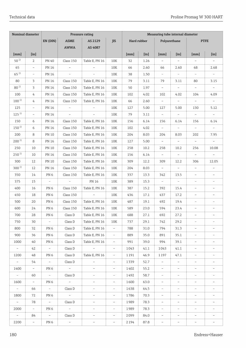
Technical data Proline Promag W 300 HART
180 Endress+Hauser
Nominal diameter Pressure rating Measuring tube internal diameter
EN (DIN) ASME AS 2129 JIS Hard rubber Polyurethane PTFE
AWWA AS 4087
[mm] [in] [mm] [in] [mm] [in] [mm] [in]
50 1) 2 PN 40 Class 150 Table E, PN 16 10K 32 1.26 – – – –
65 – PN 16 – – 10K 66 2.60 66 2.60 68 2.68
65 1) – PN 16 – – 10K 38 1.50 – – – –
80 3 PN 16 Class 150 Table E, PN 16 10K 79 3.11 79 3.11 80 3.15
80 1) 3 PN 16 Class 150 Table E, PN 16 10K 50 1.97 – – – –
100 4 PN 16 Class 150 Table E, PN 16 10K 102 4.02 102 4.02 104 4.09
100 1) 4 PN 16 Class 150 Table E, PN 16 10K 66 2.60 – – – –
125 – PN 16 – – 10K 127 5.00 127 5.00 130 5.12
125 1) – PN 16 – – 10K 79 3.11 – – – –
150 6 PN 16 Class 150 Table E, PN 16 10K 156 6.14 156 6.14 156 6.14
150 1) 6 PN 16 Class 150 Table E, PN 16 10K 102 4.02 – – – –
200 8 PN 10 Class 150 Table E, PN 16 10K 204 8.03 204 8.03 202 7.95
200 1) 8 PN 16 Class 150 Table E, PN 16 10K 127 5.00 – – – –
250 10 PN 10 Class 150 Table E, PN 16 10K 258 10.2 258 10.2 256 10.08
250 1) 10 PN 16 Class 150 Table E, PN 16 10K 156 6.14 – – – –
300 12 PN 10 Class 150 Table E, PN 16 10K 309 12.2 309 12.2 306 12.05
300 1) 12 PN 16 Class 150 Table E, PN 16 10K 204 8.03 – – – –
350 14 PN 6 Class 150 Table E, PN 16 10K 337 13.3 342 13.5 – –
375 15 – – PN 16 10K 389 15.3 – – – –
400 16 PN 6 Class 150 Table E, PN 16 10K 387 15.2 392 15.4 – –
450 18 PN 6 Class 150 – 10K 436 17.1 437 17.2 – –
500 20 PN 6 Class 150 Table E, PN 16 10K 487 19.1 492 19.4 – –
600 24 PN 6 Class 150 Table E, PN 16 10K 589 23.0 594 23.4 – –
700 28 PN 6 Class D Table E, PN 16 10K 688 27.1 692 27.2 – –
750 30 – Class D Table E, PN 16 10K 737 29.1 742 29.2 – –
800 32 PN 6 Class D Table E, PN 16 – 788 31.0 794 31.3 – –
900 36 PN 6 Class D Table E, PN 16 – 889 35.0 891 35.1 – –
1000 40 PN 6 Class D Table E, PN 16 – 991 39.0 994 39.1 – –
– 42 – Class D – – 1 043 41.1 1 043 41.1 – –
1200 48 PN 6 Class D Table E, PN 16 – 1 191 46.9 1 197 47.1 – –
– 54 – Class D – – 1 339 52.7 – – – –
1400 – PN 6 – – – 1 402 55.2 – – – –
– 60 – Class D – – 1 492 58.7 – – – –
1600 – PN 6 – – – 1 600 63.0 – – – –
– 66 – Class D – – 1 638 64.5 – – – –
1800 72 PN 6 – – – 1 786 70.3 – – – –
– 78 – Class D – – 1 989 78.3 – – – –
2000 – PN 6 – – – 1 989 78.3 – – – –
– 84 – Class D – – 2 099 84.0 – – – –
2200 – PN 6 – – – 2 194 87.8 – – – –
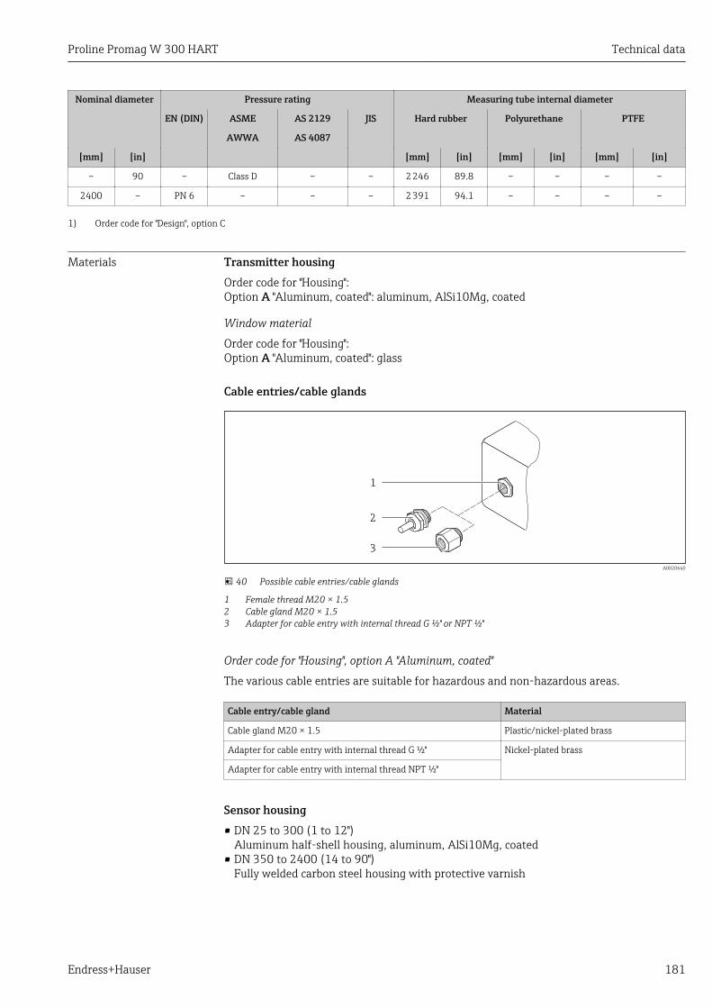
Proline Promag W 300 HART Technical data
Endress+Hauser 181
Nominal diameter Pressure rating Measuring tube internal diameter
EN (DIN) ASME AS 2129 JIS Hard rubber Polyurethane PTFE
AWWA AS 4087
[mm] [in] [mm] [in] [mm] [in] [mm] [in]
– 90 – Class D – – 2 246 89.8 – – – –
2400 – PN 6 – – – 2 391 94.1 – – – –
1) Order code for "Design", option C
Materials Transmitter housingOrder code for "Housing":Option A "Aluminum, coated": aluminum, AlSi10Mg, coated
Window material
Order code for "Housing":Option A "Aluminum, coated": glass
Cable entries/cable glands
1
2
3
A0020640
40 Possible cable entries/cable glands
1 Female thread M20 × 1.52 Cable gland M20 × 1.53 Adapter for cable entry with internal thread G ½" or NPT ½"
Order code for "Housing", option A "Aluminum, coated"
The various cable entries are suitable for hazardous and non-hazardous areas.
Cable entry/cable gland Material
Cable gland M20 × 1.5 Plastic/nickel-plated brass
Adapter for cable entry with internal thread G ½" Nickel-plated brass
Adapter for cable entry with internal thread NPT ½"
Sensor housing• DN 25 to 300 (1 to 12")
Aluminum half-shell housing, aluminum, AlSi10Mg, coated• DN 350 to 2400 (14 to 90")
Fully welded carbon steel housing with protective varnish

Technical data Proline Promag W 300 HART
182 Endress+Hauser
Measuring tubes• DN 25 to 600 (1 to 24")
Stainless steel: 1.4301, 1.4306, 304, 304L• DN 700 to 2400 (28 to 90")
Stainless steel: 1.4301, 304
Liner
• DN 25 to 300 (1 to 12"): PTFE• DN 25 to 1200 (1 to 48"): polyurethane• DN 50 to 2400 (2 to 90"): hard rubber
Electrodes• Stainless steel, 1.4435 (316L)• Alloy C22, 2.4602 (UNS N06022)• Tantalum
Process connectionsFor flanges made of carbon steel:• DN ≤ 300 (12"): with Al/Zn protective coating or protective varnish• DN ≥ 350 (14"): protective varnish
All carbon steel lap joint flanges are supplied with a hot-dip galvanized finish.
EN 1092-1 (DIN 2501)
Fixed flange• Carbon steel:
– DN ≤ 300: S235JRG2, S235JR+N, P245GH, A105, E250C– DN 350 to 2400: P245GH, S235JRG2, A105, E250C
• Stainless steel:– DN ≤ 300: 1.4404, 1.4571, F316L– DN 350 to 600: 1.4571, F316L, 1.4404– DN 700 to 1000: 1.4404, F316L
Lap joint flange• Carbon steel DN ≤ 300: S235JRG2, A105, E250C• Stainless steel DN ≤ 300: 1.4306,1.4404, 1.4571, F316L
Lap joint flange, stamped plate• Carbon steel DN ≤ 300: S235JRG2 similar to S235JR+AR or 1.0038• Stainless steel DN ≤ 300: 1.4301 similar to 304
ASME B16.5
Fixed flange, lap joint flange• Carbon steel: A105• Stainless steel: F316L
JIS B2220
• Carbon steel: A105, A350 LF2• Stainless steel: F316L
AWWA C207
Carbon steel: A105, P265GH, A181 Class 70, E250C, S275JR
AS 2129
Carbon steel: A105, E250C, P235GH, P265GH, S235JRG2
Proline Promag W 300 HART Technical data
Endress+Hauser 183
AS 4087
Carbon steel: A105, P265GH, S275JR
SealsAs per DIN EN 1514-1, form IBC
AccessoriesProtective cover
Stainless steel, 1.4404 (316L)
External WLAN antenna
• Antenna: ASA plastic (acrylic ester-styrene-acrylonitrile) and nickel-plated brass• Adapter: Stainless steel and nickel-plated brass• Cable: Polyethylene• Plug: Nickel-plated brass• Angle bracket: Stainless steel
Ground disks
• Stainless steel, 1.4435 (316L)• Alloy C22, 2.4602 (UNS N06022)• Tantalum
Fitted electrodes Measurement, reference and empty pipe detection electrodes available as standard with:• 1.4435 (316L)• Alloy C22, 2.4602 (UNS N06022)• Tantalum
Process connections • EN 1092-1 (DIN 2501)– DN ≤ 300: fixed flange (PN 10/16/25/40) = Form A, lap joint flange (PN 10/16), lap
joint flange, stamped plate (PN 10) = Form A– DN ≥ 350: fixed flange (PN 6/10/16/25) = flat face (Form B)– DN 450 to 2400: fixed flange (PN 6/10/16) = flat face (Form B)
• ASME B16.5– DN 350 to 2400 (14 to 90"): fixed flange (Class 150)– DN 25 to 600 (1 to 24"): lap joint flange (Class 150)– DN 25 to 150 (1 to 6"): fixed flange (Class 300)
• JIS B2220– DN 50 to 750: fixed flange (10K)– DN 25 to 600: fixed flange (20K)
• AWWA C207– DN 48 to 72": fixed flange (Class D)– DN 48 to 90": fixed flange (Class D)
• AS 2129– DN 50 to 1200: fixed flange (Table E)– DN 350 to 1200: fixed flange (Table E)
• AS 4087– DN 50 to 1200): fixed flange (PN 16)– DN 350 to 1200: fixed flange (PN 16)
For information on the different materials used in the process connections → 182
Surface roughness Electrodes with 1.4435 (316L); Alloy C22, 2.4602 (UNS N06022); tantalum:≤ 0.3 to 0.5 µm (11.8 to 19.7 µin)(All data relate to parts in contact with fluid)
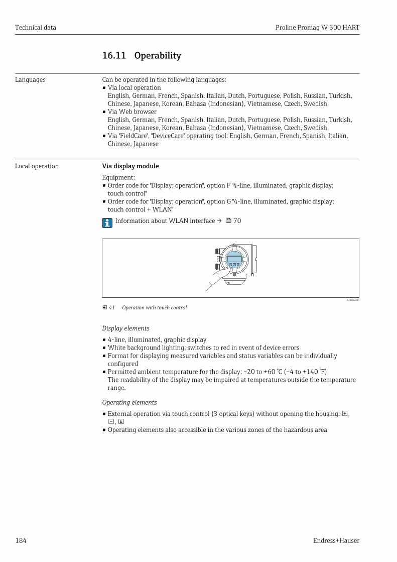
Technical data Proline Promag W 300 HART
184 Endress+Hauser
16.11 Operability
Languages Can be operated in the following languages:• Via local operation
English, German, French, Spanish, Italian, Dutch, Portuguese, Polish, Russian, Turkish,Chinese, Japanese, Korean, Bahasa (Indonesian), Vietnamese, Czech, Swedish
• Via Web browserEnglish, German, French, Spanish, Italian, Dutch, Portuguese, Polish, Russian, Turkish,Chinese, Japanese, Korean, Bahasa (Indonesian), Vietnamese, Czech, Swedish
• Via "FieldCare", "DeviceCare" operating tool: English, German, French, Spanish, Italian,Chinese, Japanese
Local operation Via display moduleEquipment:• Order code for "Display; operation", option F "4-line, illuminated, graphic display;
touch control"• Order code for "Display; operation", option G "4-line, illuminated, graphic display;
touch control + WLAN"
Information about WLAN interface → 70
A0026785
41 Operation with touch control
Display elements
• 4-line, illuminated, graphic display• White background lighting; switches to red in event of device errors• Format for displaying measured variables and status variables can be individually
configured• Permitted ambient temperature for the display: –20 to +60 °C (–4 to +140 °F)
The readability of the display may be impaired at temperatures outside the temperaturerange.
Operating elements
• External operation via touch control (3 optical keys) without opening the housing: ,,
• Operating elements also accessible in the various zones of the hazardous area
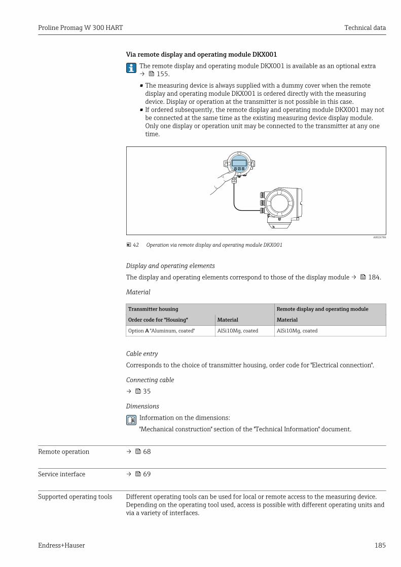
Proline Promag W 300 HART Technical data
Endress+Hauser 185
Via remote display and operating module DKX001The remote display and operating module DKX001 is available as an optional extra→ 155.
• The measuring device is always supplied with a dummy cover when the remotedisplay and operating module DKX001 is ordered directly with the measuringdevice. Display or operation at the transmitter is not possible in this case.
• If ordered subsequently, the remote display and operating module DKX001 may notbe connected at the same time as the existing measuring device display module.Only one display or operation unit may be connected to the transmitter at any onetime.
A0026786
42 Operation via remote display and operating module DKX001
Display and operating elements
The display and operating elements correspond to those of the display module → 184.
Material
Transmitter housing Remote display and operating module
Order code for "Housing" Material Material
Option A "Aluminum, coated" AlSi10Mg, coated AlSi10Mg, coated
Cable entry
Corresponds to the choice of transmitter housing, order code for "Electrical connection".
Connecting cable
→ 35
Dimensions
Information on the dimensions:
"Mechanical construction" section of the "Technical Information" document.
Remote operation → 68
Service interface → 69
Supported operating tools Different operating tools can be used for local or remote access to the measuring device.Depending on the operating tool used, access is possible with different operating units andvia a variety of interfaces.
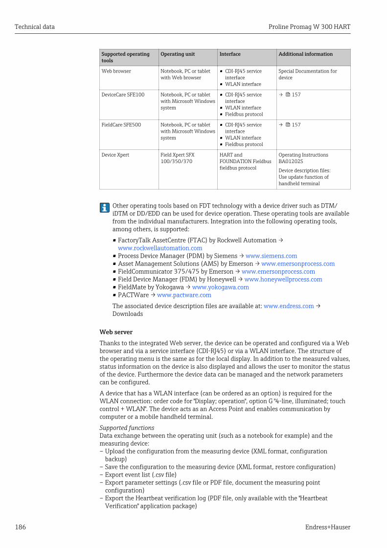
Technical data Proline Promag W 300 HART
186 Endress+Hauser
Supported operatingtools
Operating unit Interface Additional information
Web browser Notebook, PC or tabletwith Web browser
• CDI-RJ45 serviceinterface
• WLAN interface
Special Documentation fordevice
DeviceCare SFE100 Notebook, PC or tabletwith Microsoft Windowssystem
• CDI-RJ45 serviceinterface
• WLAN interface• Fieldbus protocol
→ 157
FieldCare SFE500 Notebook, PC or tabletwith Microsoft Windowssystem
• CDI-RJ45 serviceinterface
• WLAN interface• Fieldbus protocol
→ 157
Device Xpert Field Xpert SFX100/350/370
HART andFOUNDATION Fieldbusfieldbus protocol
Operating InstructionsBA01202S
Device description files:Use update function ofhandheld terminal
Other operating tools based on FDT technology with a device driver such as DTM/iDTM or DD/EDD can be used for device operation. These operating tools are availablefrom the individual manufacturers. Integration into the following operating tools,among others, is supported:
• FactoryTalk AssetCentre (FTAC) by Rockwell Automation →www.rockwellautomation.com
• Process Device Manager (PDM) by Siemens → www.siemens.com• Asset Management Solutions (AMS) by Emerson → www.emersonprocess.com• FieldCommunicator 375/475 by Emerson → www.emersonprocess.com• Field Device Manager (FDM) by Honeywell → www.honeywellprocess.com• FieldMate by Yokogawa → www.yokogawa.com• PACTWare → www.pactware.com
The associated device description files are available at: www.endress.com →Downloads
Web serverThanks to the integrated Web server, the device can be operated and configured via a Webbrowser and via a service interface (CDI-RJ45) or via a WLAN interface. The structure ofthe operating menu is the same as for the local display. In addition to the measured values,status information on the device is also displayed and allows the user to monitor the statusof the device. Furthermore the device data can be managed and the network parameterscan be configured.
A device that has a WLAN interface (can be ordered as an option) is required for theWLAN connection: order code for "Display; operation", option G "4-line, illuminated; touchcontrol + WLAN". The device acts as an Access Point and enables communication bycomputer or a mobile handheld terminal.
Supported functionsData exchange between the operating unit (such as a notebook for example) and themeasuring device:– Upload the configuration from the measuring device (XML format, configuration
backup)– Save the configuration to the measuring device (XML format, restore configuration)– Export event list (.csv file)– Export parameter settings (.csv file or PDF file, document the measuring point
configuration)– Export the Heartbeat verification log (PDF file, only available with the "Heartbeat
Verification" application package)
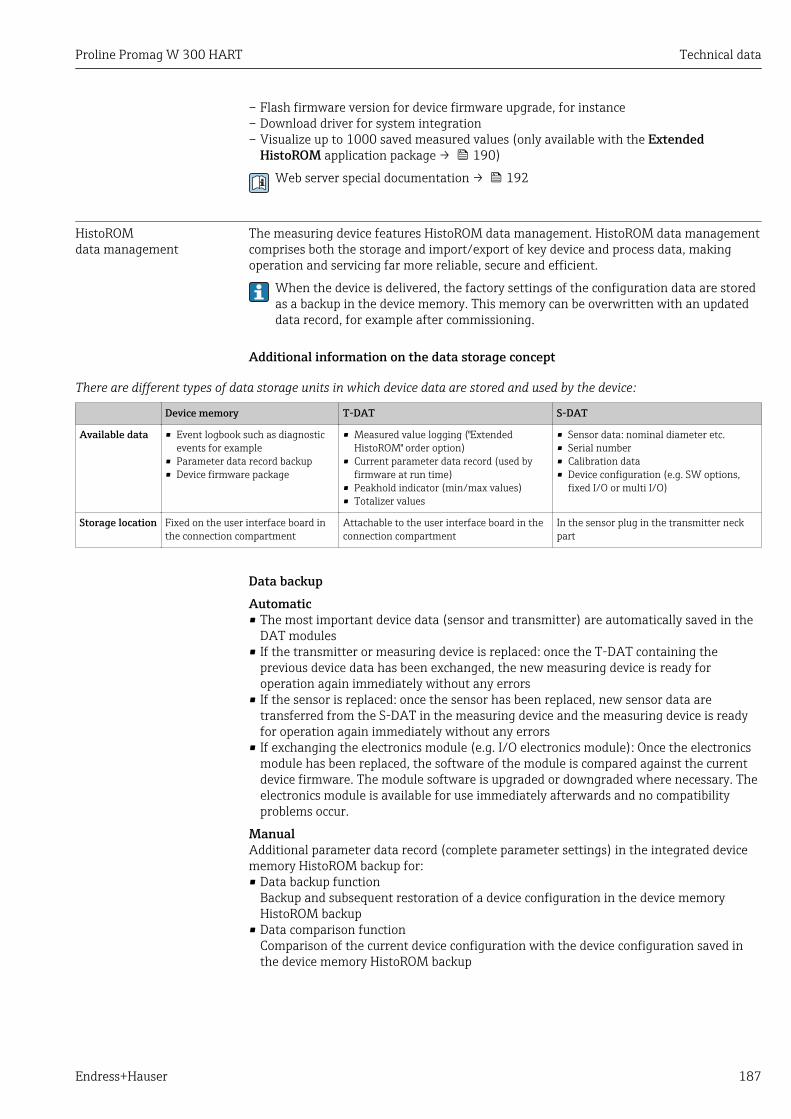
Proline Promag W 300 HART Technical data
Endress+Hauser 187
– Flash firmware version for device firmware upgrade, for instance– Download driver for system integration– Visualize up to 1000 saved measured values (only available with the Extended
HistoROM application package → 190)
Web server special documentation → 192
HistoROMdata management
The measuring device features HistoROM data management. HistoROM data managementcomprises both the storage and import/export of key device and process data, makingoperation and servicing far more reliable, secure and efficient.
When the device is delivered, the factory settings of the configuration data are storedas a backup in the device memory. This memory can be overwritten with an updateddata record, for example after commissioning.
Additional information on the data storage concept
There are different types of data storage units in which device data are stored and used by the device:
Device memory T-DAT S-DAT
Available data • Event logbook such as diagnosticevents for example
• Parameter data record backup• Device firmware package
• Measured value logging ("ExtendedHistoROM" order option)
• Current parameter data record (used byfirmware at run time)
• Peakhold indicator (min/max values)• Totalizer values
• Sensor data: nominal diameter etc.• Serial number• Calibration data• Device configuration (e.g. SW options,
fixed I/O or multi I/O)
Storage location Fixed on the user interface board inthe connection compartment
Attachable to the user interface board in theconnection compartment
In the sensor plug in the transmitter neckpart
Data backupAutomatic• The most important device data (sensor and transmitter) are automatically saved in the
DAT modules• If the transmitter or measuring device is replaced: once the T-DAT containing the
previous device data has been exchanged, the new measuring device is ready foroperation again immediately without any errors
• If the sensor is replaced: once the sensor has been replaced, new sensor data aretransferred from the S-DAT in the measuring device and the measuring device is readyfor operation again immediately without any errors
• If exchanging the electronics module (e.g. I/O electronics module): Once the electronicsmodule has been replaced, the software of the module is compared against the currentdevice firmware. The module software is upgraded or downgraded where necessary. Theelectronics module is available for use immediately afterwards and no compatibilityproblems occur.
ManualAdditional parameter data record (complete parameter settings) in the integrated devicememory HistoROM backup for:• Data backup function
Backup and subsequent restoration of a device configuration in the device memoryHistoROM backup
• Data comparison functionComparison of the current device configuration with the device configuration saved inthe device memory HistoROM backup
Technical data Proline Promag W 300 HART
188 Endress+Hauser
Data transferManualTransfer of a device configuration to another device using the export function of thespecific operating tool, e.g. with FieldCare, DeviceCare or Web server: to duplicate theconfiguration or to store in an archive (e.g. for backup purposes)
Event listAutomatic• Chronological display of up to 20 event messages in the events list• If the Extended HistoROM application package (order option) is enabled: up to 100
event messages are displayed in the events list along with a time stamp, plain textdescription and remedial measures
• The events list can be exported and displayed via a variety of interfaces and operatingtools e.g. DeviceCare, FieldCare or Web server
Data loggingManualIf the Extended HistoROM application package (order option) is enabled:• Record up to 1 000 measured values via 1 to 4 channels• User configurable recording interval• Record up to 250 measured values via each of the 4 memory channels• Export the measured value log via a variety of interfaces and operating tools e.g.
FieldCare, DeviceCare or web server
16.12 Certificates and approvalsCurrently available certificates and approvals can be called up via the productconfigurator.
CE mark The device meets the legal requirements of the applicable EU Directives. These are listed inthe corresponding EU Declaration of Conformity along with the standards applied.
Endress+Hauser confirms successful testing of the device by affixing to it the CE mark.
RCM-Tick mark The measuring system meets the EMC requirements of the "Australian Communicationsand Media Authority (ACMA)".
Ex approval The devices are certified for use in hazardous areas and the relevant safety instructions areprovided in the separate "Safety Instructions" (XA) document. Reference is made to thisdocument on the nameplate.
Pharmaceuticalcompatibility
• FDA• USP Class VI• TSE/BSE Certificate of Suitability
Drinking water approval • ACS• KTW/W270• NSF 61• WRAS BS 6920
Proline Promag W 300 HART Technical data
Endress+Hauser 189
HART certification HART interfaceThe measuring device is certified and registered by the FieldComm Group. The measuringsystem meets all the requirements of the following specifications:• Certified according to HART 7• The device can also be operated with certified devices of other manufacturers
(interoperability)
Radio approval The measuring device has radio approval.
For detailed information regarding radio approval, see Special Documentation
Measuring instrumentapproval
The measuring device is qualified to OIML R49: 2013 OIML R117 and has an OIMLCertificate of Conformity (optional).
Other standards andguidelines
• EN 60529Degrees of protection provided by enclosures (IP code)
• EN 61010-1Safety requirements for electrical equipment for measurement, control and laboratoryuse - general requirements
• IEC/EN 61326Emission in accordance with Class A requirements. Electromagnetic compatibility (EMCrequirements).
• NAMUR NE 21Electromagnetic compatibility (EMC) of industrial process and laboratory controlequipment
• NAMUR NE 32Data retention in the event of a power failure in field and control instruments withmicroprocessors
• NAMUR NE 43Standardization of the signal level for the breakdown information of digital transmitterswith analog output signal.
• NAMUR NE 53Software of field devices and signal-processing devices with digital electronics
• NAMUR NE 105Specifications for integrating fieldbus devices in engineering tools for field devices
• NAMUR NE 107Self-monitoring and diagnosis of field devices
• NAMUR NE 131Requirements for field devices for standard applications
• ETSI EN 300 328Guidelines for 2.4 GHz radio components.
• EN 301489Electromagnetic compatibility and radio spectrum matters (ERM).
16.13 Application packagesMany different application packages are available to enhance the functionality of thedevice. Such packages might be needed to address safety aspects or specific applicationrequirements.
The application packages can be ordered with the device or subsequently fromEndress+Hauser. Detailed information on the order code in question is available from yourlocal Endress+Hauser sales center or on the product page of the Endress+Hauser website:www.endress.com.
Technical data Proline Promag W 300 HART
190 Endress+Hauser
Diagnostics functions Package Description
Extended HistoROM Comprises extended functions concerning the event log and the activation of themeasured value memory.
Event log:Memory volume is extended from 20 message entries (standard version) to up to100 entries.
Data logging (line recorder):• Memory capacity for up to 1000 measured values is activated.• 250 measured values can be output via each of the 4 memory channels. The
recording interval can be defined and configured by the user.• Measured value logs can be accessed via the local display or operating tool e.g.
FieldCare, DeviceCare or Web server.
Heartbeat Technology Package Description
Heartbeat Verification+Monitoring
Heartbeat VerificationMeets the requirement for traceable verification to DIN ISO 9001:2008 Chapter7.6 a) "Control of monitoring and measuring equipment".• Functional testing in the installed state without interrupting the process.• Traceable verification results on request, including a report.• Simple testing process via local operation or other operating interfaces.• Clear measuring point assessment (pass/fail) with high test coverage within the
framework of manufacturer specifications.• Extension of calibration intervals according to operator's risk assessment.
Heartbeat MonitoringContinuously supplies data, which are characteristic of the measuring principle, toan external condition monitoring system for the purpose of preventivemaintenance or process analysis. These data enable the operator to:• Draw conclusions - using these data and other information - about the impact
process influences (such as corrosion, abrasion, buildup etc.) have on themeasuring performance over time.
• Schedule servicing in time.• Monitor the process or product quality, e.g. gas pockets.
Cleaning Package Description
Electrode cleaning circuit(ECC)
The electrode cleaning circuit (ECC) function has been developed to have a solutionfor applications where magnetite (Fe3O4) deposits frequently occur (e.g. hotwater). Since magnetite is highly conductive this build up leads to measuring errorsand ultimately to the loss of signal. The application package is designed to AVOIDbuild up of highly conductive matter and thin layers (typical of magnetite).
OPC-UA server Package Description
OPC-UA-Server The application package provides the user with an integrated OPC-UA server forcomprehensive instrument services for IoT and SCADA applications.
Special Documentation for the "OPC-UA-Server" application package→ 192.
16.14 AccessoriesOverview of accessories available for order → 155
Proline Promag W 300 HART Technical data
Endress+Hauser 191
16.15 Supplementary documentationFor an overview of the scope of the associated Technical Documentation, refer to thefollowing:• W@M Device Viewer (www.endress.com/deviceviewer): Enter the serial number
from nameplate• Endress+Hauser Operations App: Enter the serial number from the nameplate or
scan the 2D matrix code (QR code) on the nameplate
Standard documentation Brief Operating Instructions
Brief Operating Instructions for the sensor
Measuring device Documentation code
Proline Promag W KA01266D
Brief Operating Instructions for transmitter
Measuring device Documentation code
Proline 300 KA01308D
Technical Information
Measuring device Documentation code
Promag W 300 TI01414D
Description of device parameters
Measuring device Documentation code
Promag 300 GP01051D
Device-dependentadditional documentation
Safety instructionsSafety instructions for electrical equipment for hazardous areas.
Contents Documentation code
ATEX/IECEx Ex d/Ex de XA01414D
ATEX/IECEx Ex ec XA01514D
cCSAus XP XA01515D
cCSAus Ex d/ Ex de XA01516D
cCSAus Ex nA XA01517D
INMETRO Ex d/Ex de XA01518D
INMETRO Ex ec XA01519D
NEPSI Ex d/Ex de XA01520D
NEPSI Ex nA XA01521D
EAC Ex d/Ex de XA01656D
EAC Ex nA XA01657D
JPN Ex d XA01775D
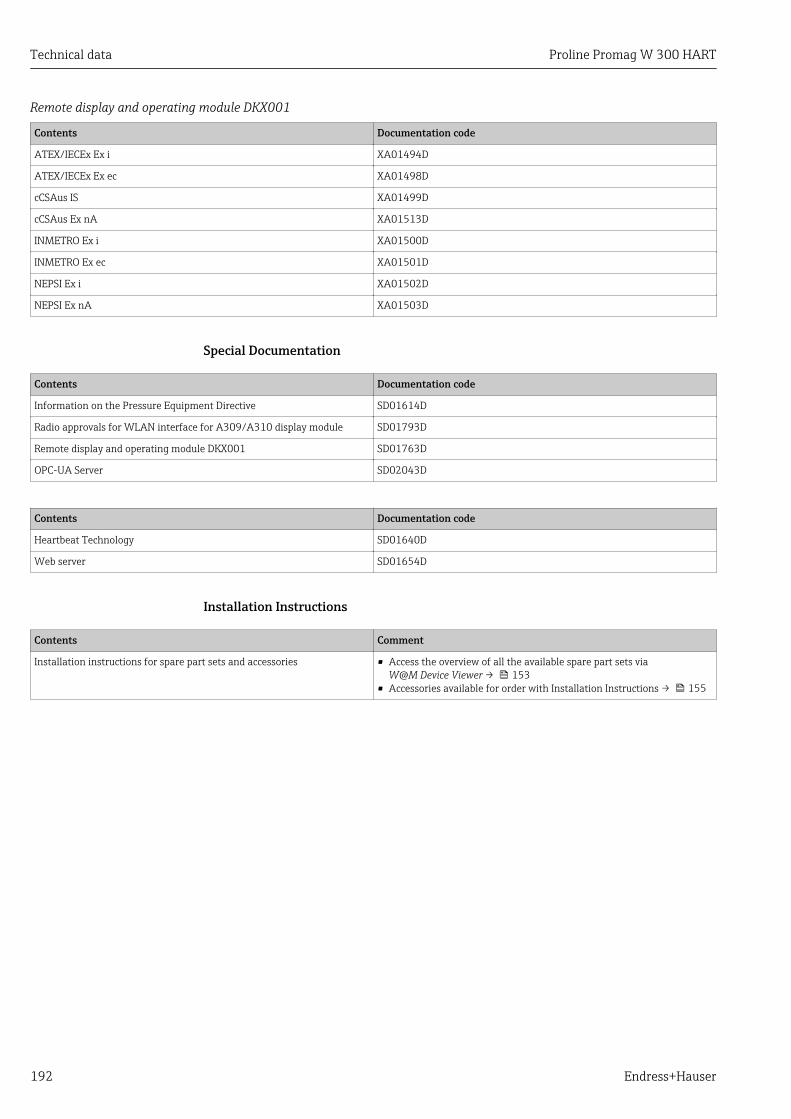
Technical data Proline Promag W 300 HART
192 Endress+Hauser
Remote display and operating module DKX001
Contents Documentation code
ATEX/IECEx Ex i XA01494D
ATEX/IECEx Ex ec XA01498D
cCSAus IS XA01499D
cCSAus Ex nA XA01513D
INMETRO Ex i XA01500D
INMETRO Ex ec XA01501D
NEPSI Ex i XA01502D
NEPSI Ex nA XA01503D
Special Documentation
Contents Documentation code
Information on the Pressure Equipment Directive SD01614D
Radio approvals for WLAN interface for A309/A310 display module SD01793D
Remote display and operating module DKX001 SD01763D
OPC-UA Server SD02043D
Contents Documentation code
Heartbeat Technology SD01640D
Web server SD01654D
Installation Instructions
Contents Comment
Installation instructions for spare part sets and accessories • Access the overview of all the available spare part sets viaW@M Device Viewer → 153
• Accessories available for order with Installation Instructions → 155
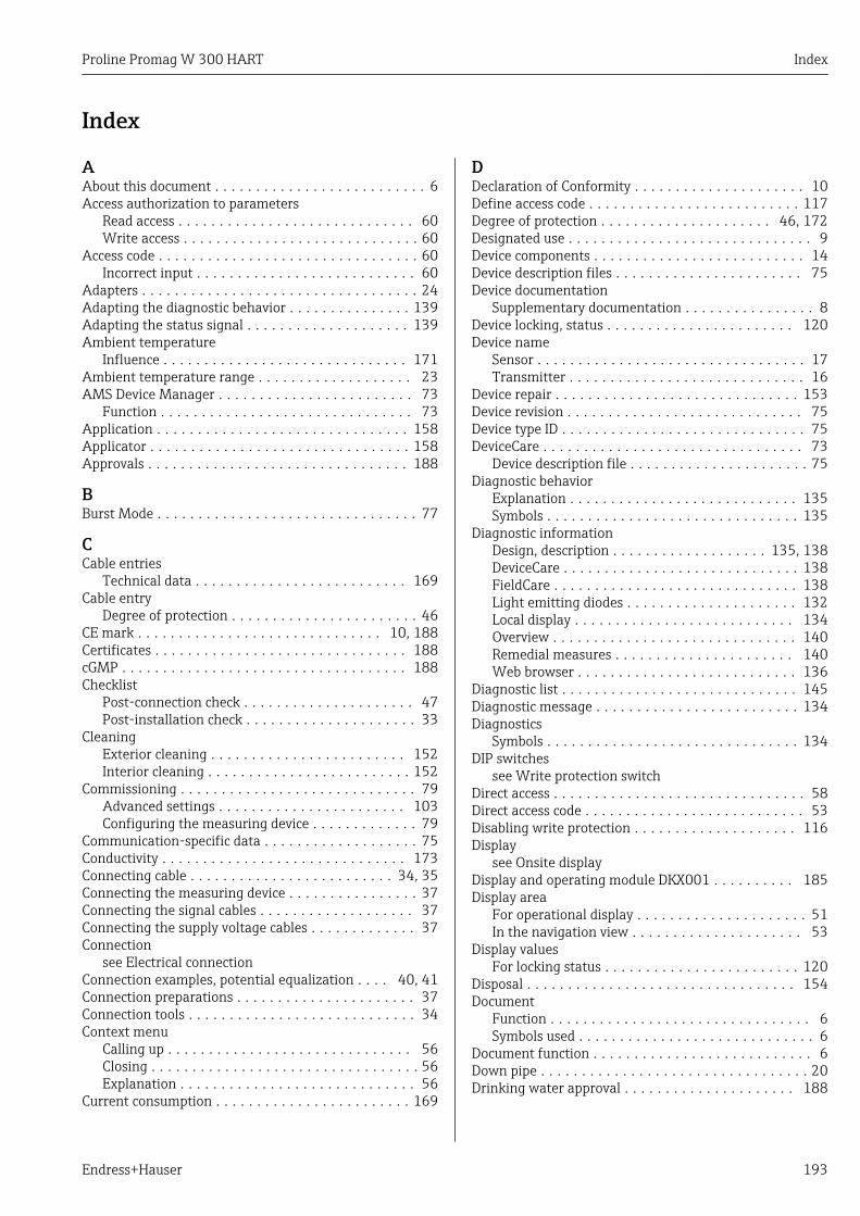
Proline Promag W 300 HART Index
Endress+Hauser 193
Index
AAbout this document . . . . . . . . . . . . . . . . . . . . . . . . . . 6Access authorization to parameters
Read access . . . . . . . . . . . . . . . . . . . . . . . . . . . . . 60Write access . . . . . . . . . . . . . . . . . . . . . . . . . . . . . 60
Access code . . . . . . . . . . . . . . . . . . . . . . . . . . . . . . . . 60Incorrect input . . . . . . . . . . . . . . . . . . . . . . . . . . . 60
Adapters . . . . . . . . . . . . . . . . . . . . . . . . . . . . . . . . . . 24Adapting the diagnostic behavior . . . . . . . . . . . . . . . 139Adapting the status signal . . . . . . . . . . . . . . . . . . . . 139Ambient temperature
Influence . . . . . . . . . . . . . . . . . . . . . . . . . . . . . . 171Ambient temperature range . . . . . . . . . . . . . . . . . . . 23AMS Device Manager . . . . . . . . . . . . . . . . . . . . . . . . 73
Function . . . . . . . . . . . . . . . . . . . . . . . . . . . . . . . 73Application . . . . . . . . . . . . . . . . . . . . . . . . . . . . . . . 158Applicator . . . . . . . . . . . . . . . . . . . . . . . . . . . . . . . . 158Approvals . . . . . . . . . . . . . . . . . . . . . . . . . . . . . . . . 188
BBurst Mode . . . . . . . . . . . . . . . . . . . . . . . . . . . . . . . . 77
CCable entries
Technical data . . . . . . . . . . . . . . . . . . . . . . . . . . 169Cable entry
Degree of protection . . . . . . . . . . . . . . . . . . . . . . . 46CE mark . . . . . . . . . . . . . . . . . . . . . . . . . . . . . . 10, 188Certificates . . . . . . . . . . . . . . . . . . . . . . . . . . . . . . . 188cGMP . . . . . . . . . . . . . . . . . . . . . . . . . . . . . . . . . . . 188Checklist
Post-connection check . . . . . . . . . . . . . . . . . . . . . 47Post-installation check . . . . . . . . . . . . . . . . . . . . . 33
CleaningExterior cleaning . . . . . . . . . . . . . . . . . . . . . . . . 152Interior cleaning . . . . . . . . . . . . . . . . . . . . . . . . . 152
Commissioning . . . . . . . . . . . . . . . . . . . . . . . . . . . . . 79Advanced settings . . . . . . . . . . . . . . . . . . . . . . . 103Configuring the measuring device . . . . . . . . . . . . . 79
Communication-specific data . . . . . . . . . . . . . . . . . . . 75Conductivity . . . . . . . . . . . . . . . . . . . . . . . . . . . . . . 173Connecting cable . . . . . . . . . . . . . . . . . . . . . . . . . 34, 35Connecting the measuring device . . . . . . . . . . . . . . . . 37Connecting the signal cables . . . . . . . . . . . . . . . . . . . 37Connecting the supply voltage cables . . . . . . . . . . . . . 37Connection
see Electrical connectionConnection examples, potential equalization . . . . 40, 41Connection preparations . . . . . . . . . . . . . . . . . . . . . . 37Connection tools . . . . . . . . . . . . . . . . . . . . . . . . . . . . 34Context menu
Calling up . . . . . . . . . . . . . . . . . . . . . . . . . . . . . . 56Closing . . . . . . . . . . . . . . . . . . . . . . . . . . . . . . . . . 56Explanation . . . . . . . . . . . . . . . . . . . . . . . . . . . . . 56
Current consumption . . . . . . . . . . . . . . . . . . . . . . . . 169
DDeclaration of Conformity . . . . . . . . . . . . . . . . . . . . . 10Define access code . . . . . . . . . . . . . . . . . . . . . . . . . . 117Degree of protection . . . . . . . . . . . . . . . . . . . . . 46, 172Designated use . . . . . . . . . . . . . . . . . . . . . . . . . . . . . . 9Device components . . . . . . . . . . . . . . . . . . . . . . . . . . 14Device description files . . . . . . . . . . . . . . . . . . . . . . . 75Device documentation
Supplementary documentation . . . . . . . . . . . . . . . . 8Device locking, status . . . . . . . . . . . . . . . . . . . . . . . 120Device name
Sensor . . . . . . . . . . . . . . . . . . . . . . . . . . . . . . . . . 17Transmitter . . . . . . . . . . . . . . . . . . . . . . . . . . . . . 16
Device repair . . . . . . . . . . . . . . . . . . . . . . . . . . . . . . 153Device revision . . . . . . . . . . . . . . . . . . . . . . . . . . . . . 75Device type ID . . . . . . . . . . . . . . . . . . . . . . . . . . . . . . 75DeviceCare . . . . . . . . . . . . . . . . . . . . . . . . . . . . . . . . 73
Device description file . . . . . . . . . . . . . . . . . . . . . . 75Diagnostic behavior
Explanation . . . . . . . . . . . . . . . . . . . . . . . . . . . . 135Symbols . . . . . . . . . . . . . . . . . . . . . . . . . . . . . . . 135
Diagnostic informationDesign, description . . . . . . . . . . . . . . . . . . . 135, 138DeviceCare . . . . . . . . . . . . . . . . . . . . . . . . . . . . . 138FieldCare . . . . . . . . . . . . . . . . . . . . . . . . . . . . . . 138Light emitting diodes . . . . . . . . . . . . . . . . . . . . . 132Local display . . . . . . . . . . . . . . . . . . . . . . . . . . . 134Overview . . . . . . . . . . . . . . . . . . . . . . . . . . . . . . 140Remedial measures . . . . . . . . . . . . . . . . . . . . . . 140Web browser . . . . . . . . . . . . . . . . . . . . . . . . . . . 136
Diagnostic list . . . . . . . . . . . . . . . . . . . . . . . . . . . . . 145Diagnostic message . . . . . . . . . . . . . . . . . . . . . . . . . 134Diagnostics
Symbols . . . . . . . . . . . . . . . . . . . . . . . . . . . . . . . 134DIP switches
see Write protection switchDirect access . . . . . . . . . . . . . . . . . . . . . . . . . . . . . . . 58Direct access code . . . . . . . . . . . . . . . . . . . . . . . . . . . 53Disabling write protection . . . . . . . . . . . . . . . . . . . . 116Display
see Onsite displayDisplay and operating module DKX001 . . . . . . . . . . 185Display area
For operational display . . . . . . . . . . . . . . . . . . . . . 51In the navigation view . . . . . . . . . . . . . . . . . . . . . 53
Display valuesFor locking status . . . . . . . . . . . . . . . . . . . . . . . . 120
Disposal . . . . . . . . . . . . . . . . . . . . . . . . . . . . . . . . . 154Document
Function . . . . . . . . . . . . . . . . . . . . . . . . . . . . . . . . 6Symbols used . . . . . . . . . . . . . . . . . . . . . . . . . . . . . 6
Document function . . . . . . . . . . . . . . . . . . . . . . . . . . . 6Down pipe . . . . . . . . . . . . . . . . . . . . . . . . . . . . . . . . . 20Drinking water approval . . . . . . . . . . . . . . . . . . . . . 188
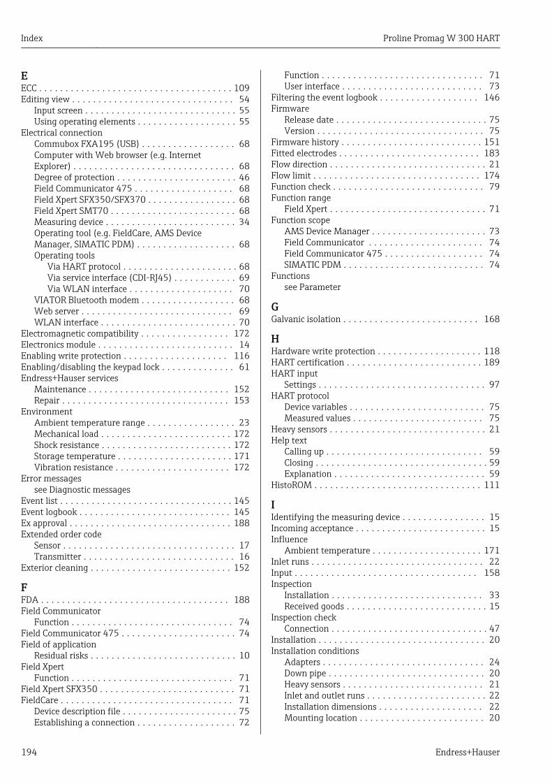
Index Proline Promag W 300 HART
194 Endress+Hauser
EECC . . . . . . . . . . . . . . . . . . . . . . . . . . . . . . . . . . . . . 109Editing view . . . . . . . . . . . . . . . . . . . . . . . . . . . . . . . 54
Input screen . . . . . . . . . . . . . . . . . . . . . . . . . . . . . 55Using operating elements . . . . . . . . . . . . . . . . . . . 55
Electrical connectionCommubox FXA195 (USB) . . . . . . . . . . . . . . . . . . 68Computer with Web browser (e.g. InternetExplorer) . . . . . . . . . . . . . . . . . . . . . . . . . . . . . . . 68Degree of protection . . . . . . . . . . . . . . . . . . . . . . . 46Field Communicator 475 . . . . . . . . . . . . . . . . . . . 68Field Xpert SFX350/SFX370 . . . . . . . . . . . . . . . . . 68Field Xpert SMT70 . . . . . . . . . . . . . . . . . . . . . . . . 68Measuring device . . . . . . . . . . . . . . . . . . . . . . . . . 34Operating tool (e.g. FieldCare, AMS DeviceManager, SIMATIC PDM) . . . . . . . . . . . . . . . . . . . 68Operating tools
Via HART protocol . . . . . . . . . . . . . . . . . . . . . . 68Via service interface (CDI-RJ45) . . . . . . . . . . . . 69Via WLAN interface . . . . . . . . . . . . . . . . . . . . 70
VIATOR Bluetooth modem . . . . . . . . . . . . . . . . . . 68Web server . . . . . . . . . . . . . . . . . . . . . . . . . . . . . 69WLAN interface . . . . . . . . . . . . . . . . . . . . . . . . . . 70
Electromagnetic compatibility . . . . . . . . . . . . . . . . . 172Electronics module . . . . . . . . . . . . . . . . . . . . . . . . . . 14Enabling write protection . . . . . . . . . . . . . . . . . . . . 116Enabling/disabling the keypad lock . . . . . . . . . . . . . . 61Endress+Hauser services
Maintenance . . . . . . . . . . . . . . . . . . . . . . . . . . . 152Repair . . . . . . . . . . . . . . . . . . . . . . . . . . . . . . . . 153
EnvironmentAmbient temperature range . . . . . . . . . . . . . . . . . 23Mechanical load . . . . . . . . . . . . . . . . . . . . . . . . . 172Shock resistance . . . . . . . . . . . . . . . . . . . . . . . . . 172Storage temperature . . . . . . . . . . . . . . . . . . . . . . 171Vibration resistance . . . . . . . . . . . . . . . . . . . . . . 172
Error messagessee Diagnostic messages
Event list . . . . . . . . . . . . . . . . . . . . . . . . . . . . . . . . . 145Event logbook . . . . . . . . . . . . . . . . . . . . . . . . . . . . . 145Ex approval . . . . . . . . . . . . . . . . . . . . . . . . . . . . . . . 188Extended order code
Sensor . . . . . . . . . . . . . . . . . . . . . . . . . . . . . . . . . 17Transmitter . . . . . . . . . . . . . . . . . . . . . . . . . . . . . 16
Exterior cleaning . . . . . . . . . . . . . . . . . . . . . . . . . . . 152
FFDA . . . . . . . . . . . . . . . . . . . . . . . . . . . . . . . . . . . . 188Field Communicator
Function . . . . . . . . . . . . . . . . . . . . . . . . . . . . . . . 74Field Communicator 475 . . . . . . . . . . . . . . . . . . . . . . 74Field of application
Residual risks . . . . . . . . . . . . . . . . . . . . . . . . . . . . 10Field Xpert
Function . . . . . . . . . . . . . . . . . . . . . . . . . . . . . . . 71Field Xpert SFX350 . . . . . . . . . . . . . . . . . . . . . . . . . . 71FieldCare . . . . . . . . . . . . . . . . . . . . . . . . . . . . . . . . . 71
Device description file . . . . . . . . . . . . . . . . . . . . . . 75Establishing a connection . . . . . . . . . . . . . . . . . . . 72
Function . . . . . . . . . . . . . . . . . . . . . . . . . . . . . . . 71User interface . . . . . . . . . . . . . . . . . . . . . . . . . . . 73
Filtering the event logbook . . . . . . . . . . . . . . . . . . . 146Firmware
Release date . . . . . . . . . . . . . . . . . . . . . . . . . . . . . 75Version . . . . . . . . . . . . . . . . . . . . . . . . . . . . . . . . 75
Firmware history . . . . . . . . . . . . . . . . . . . . . . . . . . . 151Fitted electrodes . . . . . . . . . . . . . . . . . . . . . . . . . . . 183Flow direction . . . . . . . . . . . . . . . . . . . . . . . . . . . . . . 21Flow limit . . . . . . . . . . . . . . . . . . . . . . . . . . . . . . . . 174Function check . . . . . . . . . . . . . . . . . . . . . . . . . . . . . 79Function range
Field Xpert . . . . . . . . . . . . . . . . . . . . . . . . . . . . . . 71Function scope
AMS Device Manager . . . . . . . . . . . . . . . . . . . . . . 73Field Communicator . . . . . . . . . . . . . . . . . . . . . . 74Field Communicator 475 . . . . . . . . . . . . . . . . . . . 74SIMATIC PDM . . . . . . . . . . . . . . . . . . . . . . . . . . . 74
Functionssee Parameter
GGalvanic isolation . . . . . . . . . . . . . . . . . . . . . . . . . . 168
HHardware write protection . . . . . . . . . . . . . . . . . . . . 118HART certification . . . . . . . . . . . . . . . . . . . . . . . . . . 189HART input
Settings . . . . . . . . . . . . . . . . . . . . . . . . . . . . . . . . 97HART protocol
Device variables . . . . . . . . . . . . . . . . . . . . . . . . . . 75Measured values . . . . . . . . . . . . . . . . . . . . . . . . . 75
Heavy sensors . . . . . . . . . . . . . . . . . . . . . . . . . . . . . . 21Help text
Calling up . . . . . . . . . . . . . . . . . . . . . . . . . . . . . . 59Closing . . . . . . . . . . . . . . . . . . . . . . . . . . . . . . . . . 59Explanation . . . . . . . . . . . . . . . . . . . . . . . . . . . . . 59
HistoROM . . . . . . . . . . . . . . . . . . . . . . . . . . . . . . . . 111
IIdentifying the measuring device . . . . . . . . . . . . . . . . 15Incoming acceptance . . . . . . . . . . . . . . . . . . . . . . . . . 15Influence
Ambient temperature . . . . . . . . . . . . . . . . . . . . . 171Inlet runs . . . . . . . . . . . . . . . . . . . . . . . . . . . . . . . . . 22Input . . . . . . . . . . . . . . . . . . . . . . . . . . . . . . . . . . . 158Inspection
Installation . . . . . . . . . . . . . . . . . . . . . . . . . . . . . 33Received goods . . . . . . . . . . . . . . . . . . . . . . . . . . . 15
Inspection checkConnection . . . . . . . . . . . . . . . . . . . . . . . . . . . . . . 47
Installation . . . . . . . . . . . . . . . . . . . . . . . . . . . . . . . . 20Installation conditions
Adapters . . . . . . . . . . . . . . . . . . . . . . . . . . . . . . . 24Down pipe . . . . . . . . . . . . . . . . . . . . . . . . . . . . . . 20Heavy sensors . . . . . . . . . . . . . . . . . . . . . . . . . . . 21Inlet and outlet runs . . . . . . . . . . . . . . . . . . . . . . . 22Installation dimensions . . . . . . . . . . . . . . . . . . . . 22Mounting location . . . . . . . . . . . . . . . . . . . . . . . . 20
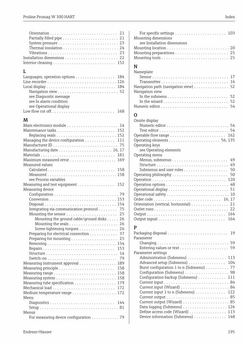
Proline Promag W 300 HART Index
Endress+Hauser 195
Orientation . . . . . . . . . . . . . . . . . . . . . . . . . . . . . 21Partially filled pipe . . . . . . . . . . . . . . . . . . . . . . . . 21System pressure . . . . . . . . . . . . . . . . . . . . . . . . . . 23Thermal insulation . . . . . . . . . . . . . . . . . . . . . . . . 24Vibrations . . . . . . . . . . . . . . . . . . . . . . . . . . . . . . 23
Installation dimensions . . . . . . . . . . . . . . . . . . . . . . . 22Interior cleaning . . . . . . . . . . . . . . . . . . . . . . . . . . . 152
LLanguages, operation options . . . . . . . . . . . . . . . . . 184Line recorder . . . . . . . . . . . . . . . . . . . . . . . . . . . . . . 126Local display . . . . . . . . . . . . . . . . . . . . . . . . . . . . . . 184
Navigation view . . . . . . . . . . . . . . . . . . . . . . . . . . 52see Diagnostic messagesee In alarm conditionsee Operational display
Low flow cut off . . . . . . . . . . . . . . . . . . . . . . . . . . . 168
MMain electronics module . . . . . . . . . . . . . . . . . . . . . . 14Maintenance tasks . . . . . . . . . . . . . . . . . . . . . . . . . 152
Replacing seals . . . . . . . . . . . . . . . . . . . . . . . . . . 152Managing the device configuration . . . . . . . . . . . . . 111Manufacturer ID . . . . . . . . . . . . . . . . . . . . . . . . . . . . 75Manufacturing date . . . . . . . . . . . . . . . . . . . . . . . 16, 17Materials . . . . . . . . . . . . . . . . . . . . . . . . . . . . . . . . 181Maximum measured error . . . . . . . . . . . . . . . . . . . . 169Measured values
Calculated . . . . . . . . . . . . . . . . . . . . . . . . . . . . . 158Measured . . . . . . . . . . . . . . . . . . . . . . . . . . . . . . 158see Process variables
Measuring and test equipment . . . . . . . . . . . . . . . . 152Measuring device
Configuration . . . . . . . . . . . . . . . . . . . . . . . . . . . . 79Conversion . . . . . . . . . . . . . . . . . . . . . . . . . . . . . 153Disposal . . . . . . . . . . . . . . . . . . . . . . . . . . . . . . . 154Integrating via communication protocol . . . . . . . . 75Mounting the sensor . . . . . . . . . . . . . . . . . . . . . . 25
Mounting the ground cable/ground disks . . . . . 26Mounting the seals . . . . . . . . . . . . . . . . . . . . . 26Screw tightening torques . . . . . . . . . . . . . . . . . 26
Preparing for electrical connection . . . . . . . . . . . . 37Preparing for mounting . . . . . . . . . . . . . . . . . . . . 25Removing . . . . . . . . . . . . . . . . . . . . . . . . . . . . . . 154Repairs . . . . . . . . . . . . . . . . . . . . . . . . . . . . . . . 153Structure . . . . . . . . . . . . . . . . . . . . . . . . . . . . . . . 14Switch-on . . . . . . . . . . . . . . . . . . . . . . . . . . . . . . 79
Measuring instrument approval . . . . . . . . . . . . . . . . 189Measuring principle . . . . . . . . . . . . . . . . . . . . . . . . 158Measuring range . . . . . . . . . . . . . . . . . . . . . . . . . . . 158Measuring system . . . . . . . . . . . . . . . . . . . . . . . . . . 158Measuring tube specification . . . . . . . . . . . . . . . . . . 179Mechanical load . . . . . . . . . . . . . . . . . . . . . . . . . . . 172Medium temperature range . . . . . . . . . . . . . . . . . . . 172Menu
Diagnostics . . . . . . . . . . . . . . . . . . . . . . . . . . . . 144Setup . . . . . . . . . . . . . . . . . . . . . . . . . . . . . . . . . . 81
MenusFor measuring device configuration . . . . . . . . . . . . 79
For specific settings . . . . . . . . . . . . . . . . . . . . . . 103Mounting dimensions
see Installation dimensionsMounting location . . . . . . . . . . . . . . . . . . . . . . . . . . . 20Mounting preparations . . . . . . . . . . . . . . . . . . . . . . . 25Mounting tools . . . . . . . . . . . . . . . . . . . . . . . . . . . . . 25
NNameplate
Sensor . . . . . . . . . . . . . . . . . . . . . . . . . . . . . . . . . 17Transmitter . . . . . . . . . . . . . . . . . . . . . . . . . . . . . 16
Navigation path (navigation view) . . . . . . . . . . . . . . . 52Navigation view
In the submenu . . . . . . . . . . . . . . . . . . . . . . . . . . 52In the wizard . . . . . . . . . . . . . . . . . . . . . . . . . . . . 52
Numeric editor . . . . . . . . . . . . . . . . . . . . . . . . . . . . . 54
OOnsite display
Numeric editor . . . . . . . . . . . . . . . . . . . . . . . . . . . 54Text editor . . . . . . . . . . . . . . . . . . . . . . . . . . . . . . 54
Operable flow range . . . . . . . . . . . . . . . . . . . . . . . . 162Operating elements . . . . . . . . . . . . . . . . . . . . . . 56, 135Operating keys
see Operating elementsOperating menu
Menus, submenus . . . . . . . . . . . . . . . . . . . . . . . . 49Structure . . . . . . . . . . . . . . . . . . . . . . . . . . . . . . . 49Submenus and user roles . . . . . . . . . . . . . . . . . . . 50
Operating philosophy . . . . . . . . . . . . . . . . . . . . . . . . 50Operation . . . . . . . . . . . . . . . . . . . . . . . . . . . . . . . . 120Operation options . . . . . . . . . . . . . . . . . . . . . . . . . . . 48Operational display . . . . . . . . . . . . . . . . . . . . . . . . . . 51Operational safety . . . . . . . . . . . . . . . . . . . . . . . . . . . 10Order code . . . . . . . . . . . . . . . . . . . . . . . . . . . . . 16, 17Orientation (vertical, horizontal) . . . . . . . . . . . . . . . . 21Outlet runs . . . . . . . . . . . . . . . . . . . . . . . . . . . . . . . . 22Output . . . . . . . . . . . . . . . . . . . . . . . . . . . . . . . . . . 164Output signal . . . . . . . . . . . . . . . . . . . . . . . . . . . . . 164
PPackaging disposal . . . . . . . . . . . . . . . . . . . . . . . . . . 19Parameter
Changing . . . . . . . . . . . . . . . . . . . . . . . . . . . . . . . 59Entering values or text . . . . . . . . . . . . . . . . . . . . . 59
Parameter settingsAdministration (Submenu) . . . . . . . . . . . . . . . . . 113Advanced setup (Submenu) . . . . . . . . . . . . . . . . 104Burst configuration 1 to n (Submenu) . . . . . . . . . . 77Configuration (Submenu) . . . . . . . . . . . . . . . . . . . 98Configuration backup (Submenu) . . . . . . . . . . . . 111Current input . . . . . . . . . . . . . . . . . . . . . . . . . . . . 84Current input (Wizard) . . . . . . . . . . . . . . . . . . . . . 84Current input 1 to n (Submenu) . . . . . . . . . . . . . 122Current output . . . . . . . . . . . . . . . . . . . . . . . . . . . 85Current output (Wizard) . . . . . . . . . . . . . . . . . . . . 85Data logging (Submenu) . . . . . . . . . . . . . . . . . . . 126Define access code (Wizard) . . . . . . . . . . . . . . . . 113Device information (Submenu) . . . . . . . . . . . . . . 148
Index Proline Promag W 300 HART
196 Endress+Hauser
Diagnostics (Menu) . . . . . . . . . . . . . . . . . . . . . . 144Display (Submenu) . . . . . . . . . . . . . . . . . . . . . . . 106Display (Wizard) . . . . . . . . . . . . . . . . . . . . . . . . . 94Double pulse output . . . . . . . . . . . . . . . . . . . . . . 101Double pulse output (Submenu) . . . . . . . . . 101, 125Electrode cleaning circuit (Submenu) . . . . . . . . . 109Empty pipe detection (Wizard) . . . . . . . . . . . . . . . 97I/O configuration . . . . . . . . . . . . . . . . . . . . . . . . . 82I/O configuration (Submenu) . . . . . . . . . . . . . . . . 82Input (Submenu) . . . . . . . . . . . . . . . . . . . . . . . . . 99Low flow cut off (Wizard) . . . . . . . . . . . . . . . . . . . 95Process variables (Submenu) . . . . . . . . . . . . . . . . 120Pulse/frequency/switch output . . . . . . . . . . . . . . . 88Pulse/frequency/switch output (Wizard) . . 88, 89, 92Pulse/frequency/switch output 1 to n (Submenu) 124Relay output . . . . . . . . . . . . . . . . . . . . . . . . . . . . . 99Relay output 1 to n (Submenu) . . . . . . . . . . . . . . 124Relay output 1 to n (Wizard) . . . . . . . . . . . . . . . . . 99Reset access code (Submenu) . . . . . . . . . . . . . . . 113Sensor adjustment (Submenu) . . . . . . . . . . . . . . 104Setup (Menu) . . . . . . . . . . . . . . . . . . . . . . . . . . . . 81Simulation (Submenu) . . . . . . . . . . . . . . . . . . . . 114Status input . . . . . . . . . . . . . . . . . . . . . . . . . . . . . 83Status input (Submenu) . . . . . . . . . . . . . . . . . . . . 83Status input 1 to n (Submenu) . . . . . . . . . . . . . . 122System units (Submenu) . . . . . . . . . . . . . . . . . . . . 81Totalizer (Submenu) . . . . . . . . . . . . . . . . . . . . . . 121Totalizer 1 to n (Submenu) . . . . . . . . . . . . . . . . . 104Totalizer handling (Submenu) . . . . . . . . . . . . . . . 125Value current output 1 to n (Submenu) . . . . . . . . 123Web server (Submenu) . . . . . . . . . . . . . . . . . . . . . 67WLAN settings (Wizard) . . . . . . . . . . . . . . . . . . 109
Partially filled pipe . . . . . . . . . . . . . . . . . . . . . . . . . . 21Performance characteristics . . . . . . . . . . . . . . . . . . . 169Pharmaceutical compatibility . . . . . . . . . . . . . . . . . . 188Post-connection check (checklist) . . . . . . . . . . . . . . . 47Post-installation check . . . . . . . . . . . . . . . . . . . . . . . 79Post-installation check (checklist) . . . . . . . . . . . . . . . 33Potential equalization . . . . . . . . . . . . . . . . . . . . . . . . 40Power consumption . . . . . . . . . . . . . . . . . . . . . . . . . 169Power supply failure . . . . . . . . . . . . . . . . . . . . . . . . 169Pressure loss . . . . . . . . . . . . . . . . . . . . . . . . . . . . . . 174Pressure tightness . . . . . . . . . . . . . . . . . . . . . . . . . . 173Pressure-temperature ratings . . . . . . . . . . . . . . . . . 173Process conditions
Conductivity . . . . . . . . . . . . . . . . . . . . . . . . . . . . 173Flow limit . . . . . . . . . . . . . . . . . . . . . . . . . . . . . 174Fluid temperature . . . . . . . . . . . . . . . . . . . . . . . 172Pressure loss . . . . . . . . . . . . . . . . . . . . . . . . . . . 174Pressure tightness . . . . . . . . . . . . . . . . . . . . . . . 173
Process connections . . . . . . . . . . . . . . . . . . . . . . . . 183Product safety . . . . . . . . . . . . . . . . . . . . . . . . . . . . . . 10Protecting parameter settings . . . . . . . . . . . . . . . . . 116
RRadio approval . . . . . . . . . . . . . . . . . . . . . . . . . . . . 189RCM-Tick mark . . . . . . . . . . . . . . . . . . . . . . . . . . . . 188Read access . . . . . . . . . . . . . . . . . . . . . . . . . . . . . . . . 60Reading measured values . . . . . . . . . . . . . . . . . . . . 120
Recalibration . . . . . . . . . . . . . . . . . . . . . . . . . . . . . . 152Reference operating conditions . . . . . . . . . . . . . . . . 169Registered trademarks . . . . . . . . . . . . . . . . . . . . . . . . . 8Remedial measures
Calling up . . . . . . . . . . . . . . . . . . . . . . . . . . . . . 136Closing . . . . . . . . . . . . . . . . . . . . . . . . . . . . . . . 136
Remote operation . . . . . . . . . . . . . . . . . . . . . . . . . . 185Repair . . . . . . . . . . . . . . . . . . . . . . . . . . . . . . . . . . . 153Repair of a device . . . . . . . . . . . . . . . . . . . . . . . . . . 153Repairs
Notes . . . . . . . . . . . . . . . . . . . . . . . . . . . . . . . . . 153Repeatability . . . . . . . . . . . . . . . . . . . . . . . . . . . . . . 171Replacement
Device components . . . . . . . . . . . . . . . . . . . . . . . 153Replacing seals . . . . . . . . . . . . . . . . . . . . . . . . . . . . 152Requirements for personnel . . . . . . . . . . . . . . . . . . . . . 9Return . . . . . . . . . . . . . . . . . . . . . . . . . . . . . . . . . . 153
SSafety . . . . . . . . . . . . . . . . . . . . . . . . . . . . . . . . . . . . . 9Screw tightening torques . . . . . . . . . . . . . . . . . . . . . . 26Sensor
Mounting . . . . . . . . . . . . . . . . . . . . . . . . . . . . . . . 25Serial number . . . . . . . . . . . . . . . . . . . . . . . . . . . 16, 17Setting the operating language . . . . . . . . . . . . . . . . . 79Settings
Adapting the measuring device to the processconditions . . . . . . . . . . . . . . . . . . . . . . . . . . . . . 125Administration . . . . . . . . . . . . . . . . . . . . . . . . . . 112Advanced display configurations . . . . . . . . . . . . . 106Current input . . . . . . . . . . . . . . . . . . . . . . . . . . . . 84Current output . . . . . . . . . . . . . . . . . . . . . . . . . . . 85Device reset . . . . . . . . . . . . . . . . . . . . . . . . . . . . 148Device tag . . . . . . . . . . . . . . . . . . . . . . . . . . . . . . 81Double pulse output . . . . . . . . . . . . . . . . . . . . . . 101Electrode cleaning circuit (ECC) . . . . . . . . . . . . . . 109Empty pipe detection (EPD) . . . . . . . . . . . . . . . . . 97HART input . . . . . . . . . . . . . . . . . . . . . . . . . . . . . 97I/O configuration . . . . . . . . . . . . . . . . . . . . . . . . . 82Local display . . . . . . . . . . . . . . . . . . . . . . . . . . . . 94Low flow cut off . . . . . . . . . . . . . . . . . . . . . . . . . . 95Managing the device configuration . . . . . . . . . . . 111Operating language . . . . . . . . . . . . . . . . . . . . . . . 79Pulse output . . . . . . . . . . . . . . . . . . . . . . . . . . . . . 88Pulse/frequency/switch output . . . . . . . . . . . . 88, 89Relay output . . . . . . . . . . . . . . . . . . . . . . . . . . . . . 99Resetting the totalizer . . . . . . . . . . . . . . . . . . . . 125Sensor adjustment . . . . . . . . . . . . . . . . . . . . . . . 104Simulation . . . . . . . . . . . . . . . . . . . . . . . . . . . . . 114Status input . . . . . . . . . . . . . . . . . . . . . . . . . . . . . 83Switch output . . . . . . . . . . . . . . . . . . . . . . . . . . . . 92System units . . . . . . . . . . . . . . . . . . . . . . . . . . . . 81Totalizer . . . . . . . . . . . . . . . . . . . . . . . . . . . . . . 104Totalizer reset . . . . . . . . . . . . . . . . . . . . . . . . . . 125WLAN . . . . . . . . . . . . . . . . . . . . . . . . . . . . . . . . 109
Shock resistance . . . . . . . . . . . . . . . . . . . . . . . . . . . 172Showing data logging . . . . . . . . . . . . . . . . . . . . . . . 126Signal on alarm . . . . . . . . . . . . . . . . . . . . . . . . . . . . 167
Proline Promag W 300 HART Index
Endress+Hauser 197
SIMATIC PDM . . . . . . . . . . . . . . . . . . . . . . . . . . . . . . 74Function . . . . . . . . . . . . . . . . . . . . . . . . . . . . . . . 74
Software release . . . . . . . . . . . . . . . . . . . . . . . . . . . . 75Spare part . . . . . . . . . . . . . . . . . . . . . . . . . . . . . . . . 153Spare parts . . . . . . . . . . . . . . . . . . . . . . . . . . . . . . . 153Special connection instructions . . . . . . . . . . . . . . . . . 42Standards and guidelines . . . . . . . . . . . . . . . . . . . . . 189Status area
For operational display . . . . . . . . . . . . . . . . . . . . . 51In the navigation view . . . . . . . . . . . . . . . . . . . . . 53
Status signals . . . . . . . . . . . . . . . . . . . . . . . . . 134, 137Storage concept . . . . . . . . . . . . . . . . . . . . . . . . . . . . 187Storage conditions . . . . . . . . . . . . . . . . . . . . . . . . . . . 18Storage temperature . . . . . . . . . . . . . . . . . . . . . . . . . 18Storage temperature range . . . . . . . . . . . . . . . . . . . 171Structure
Measuring device . . . . . . . . . . . . . . . . . . . . . . . . . 14Operating menu . . . . . . . . . . . . . . . . . . . . . . . . . . 49
SubmenuAdministration . . . . . . . . . . . . . . . . . . . . . . 112, 113Advanced setup . . . . . . . . . . . . . . . . . . . . . 103, 104Burst configuration 1 to n . . . . . . . . . . . . . . . . . . . 77Configuration . . . . . . . . . . . . . . . . . . . . . . . . . . . . 98Configuration backup . . . . . . . . . . . . . . . . . . . . . 111Current input 1 to n . . . . . . . . . . . . . . . . . . . . . . 122Data logging . . . . . . . . . . . . . . . . . . . . . . . . . . . 126Device information . . . . . . . . . . . . . . . . . . . . . . . 148Display . . . . . . . . . . . . . . . . . . . . . . . . . . . . . . . . 106Double pulse output . . . . . . . . . . . . . . . . . . 101, 125Electrode cleaning circuit . . . . . . . . . . . . . . . . . . 109Event list . . . . . . . . . . . . . . . . . . . . . . . . . . . . . . 145HART input . . . . . . . . . . . . . . . . . . . . . . . . . . . . . 97I/O configuration . . . . . . . . . . . . . . . . . . . . . . . . . 82Input . . . . . . . . . . . . . . . . . . . . . . . . . . . . . . . . . . 99Input values . . . . . . . . . . . . . . . . . . . . . . . . . . . . 122Output values . . . . . . . . . . . . . . . . . . . . . . . . . . . 123Overview . . . . . . . . . . . . . . . . . . . . . . . . . . . . . . . 50Process variables . . . . . . . . . . . . . . . . . . . . . . . . 120Pulse/frequency/switch output 1 to n . . . . . . . . . 124Relay output 1 to n . . . . . . . . . . . . . . . . . . . . . . . 124Reset access code . . . . . . . . . . . . . . . . . . . . . . . . 113Sensor adjustment . . . . . . . . . . . . . . . . . . . . . . . 104Simulation . . . . . . . . . . . . . . . . . . . . . . . . . . . . . 114Status input . . . . . . . . . . . . . . . . . . . . . . . . . . . . . 83Status input 1 to n . . . . . . . . . . . . . . . . . . . . . . . 122System units . . . . . . . . . . . . . . . . . . . . . . . . . . . . 81Totalizer . . . . . . . . . . . . . . . . . . . . . . . . . . . . . . 121Totalizer 1 to n . . . . . . . . . . . . . . . . . . . . . . . . . . 104Totalizer handling . . . . . . . . . . . . . . . . . . . . . . . 125Value current output 1 to n . . . . . . . . . . . . . . . . . 123Web server . . . . . . . . . . . . . . . . . . . . . . . . . . . . . 67
Supplementary documentation . . . . . . . . . . . . . . . . 191Supply voltage . . . . . . . . . . . . . . . . . . . . . . . . . . . . . 168Surface roughness . . . . . . . . . . . . . . . . . . . . . . . . . . 183Switch output . . . . . . . . . . . . . . . . . . . . . . . . . . . . . 166Symbols
Controlling data entries . . . . . . . . . . . . . . . . . . . . 55For communication . . . . . . . . . . . . . . . . . . . . . . . 51For diagnostic behavior . . . . . . . . . . . . . . . . . . . . 51
For locking . . . . . . . . . . . . . . . . . . . . . . . . . . . . . . 51For measured variable . . . . . . . . . . . . . . . . . . . . . 51For measurement channel number . . . . . . . . . . . . 51For menus . . . . . . . . . . . . . . . . . . . . . . . . . . . . . . 53For parameters . . . . . . . . . . . . . . . . . . . . . . . . . . . 53For status signal . . . . . . . . . . . . . . . . . . . . . . . . . . 51For submenu . . . . . . . . . . . . . . . . . . . . . . . . . . . . 53For wizard . . . . . . . . . . . . . . . . . . . . . . . . . . . . . . 53In the status area of the local display . . . . . . . . . . . 51Input screen . . . . . . . . . . . . . . . . . . . . . . . . . . . . . 55Operating elements . . . . . . . . . . . . . . . . . . . . . . . 55
System designMeasuring system . . . . . . . . . . . . . . . . . . . . . . . 158see Measuring device design
System integration . . . . . . . . . . . . . . . . . . . . . . . . . . 75System pressure . . . . . . . . . . . . . . . . . . . . . . . . . . . . 23
TTechnical data, overview . . . . . . . . . . . . . . . . . . . . . 158Temperature range
Ambient temperature range for display . . . . . . . . 184Storage temperature . . . . . . . . . . . . . . . . . . . . . . . 18
Terminal assignment . . . . . . . . . . . . . . . . . . . . . . . . . 37terminals . . . . . . . . . . . . . . . . . . . . . . . . . . . . . . . . 169Text editor . . . . . . . . . . . . . . . . . . . . . . . . . . . . . . . . 54Thermal insulation . . . . . . . . . . . . . . . . . . . . . . . . . . 24Tool tip
see Help textTools
Electrical connection . . . . . . . . . . . . . . . . . . . . . . 34For mounting . . . . . . . . . . . . . . . . . . . . . . . . . . . . 25Transport . . . . . . . . . . . . . . . . . . . . . . . . . . . . . . . 18
TotalizerConfiguration . . . . . . . . . . . . . . . . . . . . . . . . . . . 104
TransmitterTurning the display module . . . . . . . . . . . . . . . . . 32Turning the housing . . . . . . . . . . . . . . . . . . . . . . . 32
Transporting the measuring device . . . . . . . . . . . . . . 18Troubleshooting
General . . . . . . . . . . . . . . . . . . . . . . . . . . . . . . . 130TSE/BSE Certificate of Suitability . . . . . . . . . . . . . . . 188Turning the display module . . . . . . . . . . . . . . . . . . . . 32Turning the electronics housing
see Turning the transmitter housingTurning the transmitter housing . . . . . . . . . . . . . . . . 32
UUse of the measuring device
Borderline cases . . . . . . . . . . . . . . . . . . . . . . . . . . . 9Incorrect use . . . . . . . . . . . . . . . . . . . . . . . . . . . . . 9see Designated use
User interfaceCurrent diagnostic event . . . . . . . . . . . . . . . . . . . 144Previous diagnostic event . . . . . . . . . . . . . . . . . . 144
User roles . . . . . . . . . . . . . . . . . . . . . . . . . . . . . . . . . 50USP Class VI . . . . . . . . . . . . . . . . . . . . . . . . . . . . . . 188
VVersion data for the device . . . . . . . . . . . . . . . . . . . . 75
Index Proline Promag W 300 HART
198 Endress+Hauser
Vibration resistance . . . . . . . . . . . . . . . . . . . . . . . . 172Vibrations . . . . . . . . . . . . . . . . . . . . . . . . . . . . . . . . . 23
WW@M . . . . . . . . . . . . . . . . . . . . . . . . . . . . . . 152, 153W@M Device Viewer . . . . . . . . . . . . . . . . . . . . 15, 153Weight
Transport (notes) . . . . . . . . . . . . . . . . . . . . . . . . . 18Wizard
Current input . . . . . . . . . . . . . . . . . . . . . . . . . . . . 84Current output . . . . . . . . . . . . . . . . . . . . . . . . . . 85Define access code . . . . . . . . . . . . . . . . . . . . . . . 113Display . . . . . . . . . . . . . . . . . . . . . . . . . . . . . . . . . 94Empty pipe detection . . . . . . . . . . . . . . . . . . . . . . 97Low flow cut off . . . . . . . . . . . . . . . . . . . . . . . . . . 95Pulse/frequency/switch output . . . . . . . . . 88, 89, 92Relay output 1 to n . . . . . . . . . . . . . . . . . . . . . . . . 99WLAN settings . . . . . . . . . . . . . . . . . . . . . . . . . . 109
WLAN settings . . . . . . . . . . . . . . . . . . . . . . . . . . . . 109Workplace safety . . . . . . . . . . . . . . . . . . . . . . . . . . . 10Write access . . . . . . . . . . . . . . . . . . . . . . . . . . . . . . . 60Write protection
Via access code . . . . . . . . . . . . . . . . . . . . . . . . . . 117Via write protection switch . . . . . . . . . . . . . . . . . 118
Write protection switch . . . . . . . . . . . . . . . . . . . . . . 118


www.addresses.endress.com