Embed Size (px)
Citation preview

University of Victoria
Faculty of Engineering
Summer 2008 ELEC 499 Design Project Report
Project Whitesnake:
Microcontroller-Based Guitar
Trainer
Victoria, British Columbia
August 1, 2008
Project 3: Sumeet Leekha: 0536687 Colin MacIntosh: 0423916 Andrew Nelder: 0422391 Evan Power: 0536575 David Zhao: 0331350
In partial fulfillment of the requirements of the B.Eng Degree

1
August 1, 2008 Project 3: Microcontroller-Based Guitar Trainer University of Victoria Victoria, BC Dr. Mihai Sima Faculty of Engineering University of Victoria P.O. Box 3055 Victoria, B.C. V8W 3P6 Dear Dr. Sima, Please accept the following report entitled “Project Whitesnake: Microcontroller-Based Guitar Trainer” as the final report for the ELEC/CENG 499 project class. The purpose of this project was to design and build an instrument that would serve as an alternative to expensive lessons when the user is beginning to play. What follows is a case study outlining the steps taken to create a proof of concept with a simple acoustic guitar. The guitar was designed to sense which strings were being pressed against which frets at any given time. Using this information, a computer would then compare what was being played against what was required to be played. The computer then let the user know if the input note was correct or incorrect. It is in this functionality that our project combines the inexpensiveness of teaching yourself how to play, and also the feedback provided by an instructor. The project involved designing and assembling the circuitry necessary to detect the chords, writing firmware for USB communication and PIC control, and creating a simple user interface that would provide the user with feedback as well as keeping him/her interested. Sincerely, Sumeet Leekha Colin MacIntosh Andrew Nelder Evan Power David Zhao

2
Table of Contents
1. Summary ..................................................................................................................... 4
2. Introduction ................................................................................................................. 4
2.1. Problem Description ............................................................................................. 4
2.2. Initial Design ........................................................................................................ 5
3. Hardware ..................................................................................................................... 6
3.1. General Circuitry ..................................................................................................... 6
3.2. PIC 18F4455 ........................................................................................................ 9
3.3. USB Firmware.................................................................................................... 10
3.4. String Energizing and Fret Reading ................................................................... 13
4. Software .................................................................................................................... 15
4.1. Introduction ........................................................................................................ 15
4.2. Language Determination .................................................................................... 15
4.3. LWJGL and OpenGL ......................................................................................... 16
4.4. Architecture Overview ....................................................................................... 17
4.5. Whitesnake Core ................................................................................................ 19
4.6. Assembly Layer.................................................................................................. 20
5. Discussion ................................................................................................................. 28
6. Conclusions ............................................................................................................... 30
7. Recommendations ..................................................................................................... 30
8. List of References ..................................................................................................... 31
9. Glossary and List of Symbols ................................................................................... 31

3
List of Figures
Figure 1: Circuit Built for USB Communication ................................................................ 7 Figure 2: Wiring Diagram for Strings and Frets ................................................................. 8 Figure 3: Pin out for 18F4455 ............................................................................................. 9 Figure 4: Circuit Diagram for Strings and Multiplexers ................................................... 14 Figure 5: Flowchart for PIC Firmware ............................................................................. 14 Figure 6: Package Diagram for Whitesnake ..................................................................... 18 Figure 7: Class Diagram for the Core Game Logic .......................................................... 21 Figure 8: Class Diagram for Assembly Layer .................................................................. 23 Figure 9: Entity Components of the Graphical Layer ....................................................... 26
List of Tables
Table 1: Pin connections used for PIC 18F4455 .............................................................. 10

4
1. Summary
Learning to play an instrument can be an expensive process. Project Whitesnake was
developed to provide a cheaper, more entertaining alternative to lessons, while still
offering feedback. This was done by creating a guitar that detects which strings are
touching which frets, and combined with a computer game interface, tells the user
whether the note is right or wrong.
The initial design for the guitar involved energizing one string at a time with 5V. If the
string was pressed onto a fret, that fret would, through a multiplexer, be recorded in the
microcontroller. Once the all 6 strings had been pulsed, and the frets to which they were
touching had been recorded, the microcontroller would then output to the computer, via
USB, the string number followed by which fret that string was touching.
The program that ran the user interface would generate a random chord from a predefined
database, graphically display it on a fret board and wait for input from the USB port.
After receiving the played chord from the guitar, the program would then compare what
was being played to what was being prompted. It would then output whether or not the
chord played was correct.
2. Introduction
2.1. Problem Description
Learning to play a musical instrument can be an expensive and difficult process.
Instructors cost approximately $30 per lesson, with a minimum of 20 lessons to become

5
comfortable with playing. There are many websites dedicated to teaching musical
instruments such as the guitar, as well as numerous devices that, using audio signal
processing, allow the user to slow down a musical track and play along to it. Both of
these methods offer some degree of instruction, but do not provide any sort of feedback
as to whether the student is right or wrong.
Project Whitesnake was created to design a cheap and entertaining way to self-instruct
aspiring musicians. This was done by designing an instrument that would provide
feedback while instructing the student. After learning the basics of the instrument, the
user could then use the game feature in the software to play along with well known
songs. This would help the user practice with the instrument while being enjoyable at the
same time. Project Whitesnake was designed for all ages, but could be especially useful
for children who despise the repetitive practicing that comes with learning an instrument.
For the purposes of this report, an acoustic guitar prototype was created as a proof of
concept that showed the technology was viable, and would be possible to apply to
numerous other stringed instruments.
2.2. Initial Design
The guitar created would detect which strings were being pressed by individually
energizing each string with 5V. When an energized string was pressed to the fret board,
the frets touching the string would then become energized. This would trigger ‘logic
high’ on the multiplexers that the frets were wired to. The multiplexers would decode
which frets were being energized at any given time, and output this to the PIC. The PIC

6
would read the output from the multiplexers for every string, and decode this into the
actual fret number and store it in memory. After all six strings had been read, the PIC
would send the fret numbers and the corresponding strings to the computer via USB.
In the most basic version of the software, a chord, randomly generated from a predefined
database, would be displayed on the screen, prompting the user to play it. As the
information from the USB was received and translated, the program would compare the
chord played to the chord displayed, letting the user know if the note played was correct
or incorrect. If the played chord was correct, a new chord would be displayed, and the
user would be prompted to play the new chord. If the played chord was incorrect, the
same chord would not be removed until the user correctly played it. In more advanced
versions of the software, the user would be able to choose from a variety of modes; he
could play the trainer version, which is what is described above, a more advanced version
of the trainer mode, where the fingerings of the chord are not displayed, only the letter
name, and a final play-along mode, in which the user is able to choose a song from a
database and play-along to it, with or with out chords being prompted.
3. Hardware
3.1. General Circuitry
The core of the hardware was the PIC 18F4455 that was used to control the strobing of
the strings, the decoding of the multiplexers and the USB communication with the
computer. There was, however a substantial amount of wiring necessary to allow the
overall system to work. A special circuit needed to be built in order to allow the PIC to

7
communicate successfully with the computer via USB. The circuit was found online, and
is shown below, in figure1.
Figure 1: Circuit Built for USB Communication
Attached to pin one, in the top left corner of the IC, is the reset button, which, when
pressed, will tell the processor to exit all programs and restart from the beginning. Pins
13 and 14 were attached to the oscillator, figure 1 shows a 20 MHz crystal, but for the
purposes of this project, a 4 MHz oscillator was used. The 4MHz crystal was chosen
because it was the lowest clock frequency that would allow the USB module to operate,
and a low frequency was desired for easier breadboard prototyping. Pins 22 and 23 were
V+ and V- for the USB. Because the circuit was powered from the USB bus power, pin 3
was used to detect the presence of 5V from the USB bus. Capacitors were connected at
various points throughout the circuit, as recommended by the PIC datasheet, to reduce the
high frequency switching noise. Because the USB module operated at particularly high
frequencies it was a significant source of noise.
8
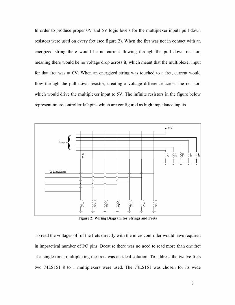
In order to produce proper 0V and 5V logic levels for the multiplexer inputs pull down
resistors were used on every fret (see figure 2). When the fret was not in contact with an
energized string there would be no current flowing through the pull down resistor,
meaning there would be no voltage drop across it, which meant that the multiplexer input
for that fret was at 0V. When an energized string was touched to a fret, current would
flow through the pull down resistor, creating a voltage difference across the resistor,
which would drive the multiplexer input to 5V. The infinite resistors in the figure below
represent microcontroller I/O pins which are configured as high impedance inputs.
Figure 2: Wiring Diagram for Strings and Frets
To read the voltages off of the frets directly with the microcontroller would have required
in impractical number of I/O pins. Because there was no need to read more than one fret
at a single time, multiplexing the frets was an ideal solution. To address the twelve frets
two 74LS151 8 to 1 multiplexers were used. The 74LS151 was chosen for its wide
9
availability, low cost, and it met the switching speed requirements of our system. The
first seven frets were connected to the inputs of the first multiplexer. The eighth input
was connected to the output of the second multiplexer. Frets eight through twelve were
connected to the inputs of the multiplexers. This way each fret was uniquely addressable
and only one input pin and eight output pins were needed on the microcontroller. Also
because not all of the inputs of the multiplexers were used, the system could easily be
expanded to read more frets without the need for additional hardware.
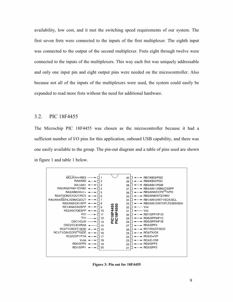
3.2. PIC 18F4455
The Microchip PIC 18F4455 was chosen as the microcontroller because it had a
sufficient number of I/O pins for this application, onboard USB capability, and there was
one easily available to the group. The pin-out diagram and a table of pins used are shown
in figure 1 and table 1 below.
Figure 3: Pin out for 18F4455

10
Table 1: Pin connections used for PIC 18F4455
Pin
Number Pin Label Pin Connection Notes
Pin
Number
Pin
Label
Pin
Connection Notes
1 MCLR / Vpp Reset Switch 21 RD2 Multiplexer
2
2 RA0 N/C 22 RD3 Multiplexer
2
3 RA1 Vcc USB Bus Sense
23 D- USB D- Pin Through 10Ω Resistor
4 RA2 Multiplexer output
Input from Multiplexer
24 D+ USB D+ Pin Through 10Ω Resistor
5 RA3 N/C 25 RC6 N/C
6 RA4 N/C 26 RC7 N/C
7 RA5 N/C 27 RD4 Multiplexer 1 Enable
8 RE0 N/C 28 RD5 Multiplexer
1
9 RE1 N/C 29 RD6 Multiplexer
1
10 RE2 N/C 30 RD7 Multiplexer
1
11 VDD VCC 31 VSS GND
12 VSS GND 32 VDD VCC
13 OSC1 4MHz Crystal 15pF
Capacitor to ground
33 RB0 String 1
14 OSC2 4MHz Crystal 15pF
Capacitor to ground
34 RB1 String 2
15 RC0 N/C 35 RB2 String 3
16 RC1 N/C 36 RB3 String 4
17 RC2 N/C 37 RB4 String 5
18 VUSB 470nF Capacitor
to GND 38 RB5 String 6
19 RD0 Multiplexer 2 Enable
39 RB6 N/C
20 RD1 Multiplexer 2 40 RB7 N/C
3.3. USB Firmware
One of the main challenges in developing the firmware for this project was
communication with the PC via USB. The original firmware was written in a third party
language called PICBasic because it seemed that communication to the PC would be
simpler in this language. The code to energize the strings and read the frets was fairly
trivial and would be very similar regardless of the language chosen.

11
Upon testing the PICBasic code it was found that the USB communication was working
only intermittently. The PICBasic language did not give sufficient control over the USB
module for this problem to be addressed. In light of this problem the PICBasic language
was abandoned and instead Microchip C18 was used. C18 is a freely available C
compiler created and distributed by Microchip. Also nearly all of the application notes
provided by Microchip used the C18 language.
The USB communication was based on the Microchip Full Speed USB (MCHPFSUSB)
Framework, which is freely available from the Microchip website. This framework
provided several sets of example code and drivers for many different types of USB
devices for different applications. The most applicable example to this project was the
USB CDC (Communications Device Class) example. CDC is one of many standard
device types are natively supported by operating systems, and therefore allow for easy
portability across platforms. When CDC is used, devices appear to the operating system
to be a standard serial port, which allows for much simpler communication. While using
the PIC as a CDC, the USB communications could be temporarily implemented using an
RS-232 connection without any changes in the PC implementation.
The framework provided by Microchip was designed to be used with a specific PIC
evaluation board, which used a different microcontroller (18F4550) and had different I/O
and the clock frequencies than the board used for this project. These differences made it
necessary to make modifications to the provided code: The USB detect pin, (used to
detect the presence of the USB bus) was changed because the original USB bus detect pin

12
was already in use. Because the microcontroller is capable of operating (and in fact
operates more easily) at lower frequencies than is necessary for USB communication, a
phase-locked loop inside microcontroller generates the clock signal. The provided sample
code was written for a 16 MHz microcontroller clock frequency, and as such, the
prescaler for the phase locked loop as a 4 MHz frequency was used for this project.
The MCHPFSUSB CDC framework provides developers with several functions for
communicating with the PC. Because this project required only one-way communication,
only a few of these functions were used. The InitializeSystem function, called once at the
beginning of the code, ensured that there was five volts on the USB V+ pin, that the
phase locked loop was stable, and established a connection with the host USB controller.
The mUSBUSARTIsTxTrfReady function simply checked the status of the USB module
and returned a true value if the module was ready to transmit and a false value otherwise.
To send data to the virtual communication port, putsUSBUSART was used. This function
required an input of a pointer to a null terminated array in the microcontroller’s RAM.
The contents of this array were transmitted to the PC. The controller of a USB bus will
drop inactive devices from the bus after a certain period of inactivity. If this happened the
microcontroller’s connection to the USB bus would need to be re-initialized. This would
cause problems in the PC software because the virtual communication port would need to
be re-opened. In order to prevent this disconnection, the USBTasks function was called
periodically. This function does not transmit any data to the PC; it simply indicates to the
bus controller that the device is still present on the bus and that the connection should
remain open.

13
3.4. String Energizing and Fret Reading
As stated previously, in order to read the frets, a voltage was applied to each of the
strings (individually), and checking for that voltage on each of the frets. If a voltage was
read on one of the frets, the user was pressing a string to that fret. Voltage was only
applied to one string at a time so that simple binary logic could be used for fret reading.
Unfortunately, if one string was high at a time, a short circuit could occur if two strings
were pressed to the same fret. One string would be at zero volts while the other was at
five volts, which would cause unreliable readings, as well as potential damage to the
microcontroller. To avoid this, when a string was not set to logic high it was configured
as a high impedance input. This was accomplished by modifying the data direction
register of the string port every time a different string was selected.
Once a string was set to logic high the frets were addressed one at a time through the
multiplexers. The fret closest to the body of the guitar was read first because when a sting
is pressed to a fret, it also touches the fret behind the desired fret. Because the string is
still resonating off the lower fret, this has no effect on the sound and is not considered an
error on the user’s behalf. To avoid reading the incorrect fret, they were read from the
bell of the guitar up towards the head. When a high logic level is read on one of the frets
the string number and fret number stored in array. The string number was then
incremented and the process was repeated for all six strings. After all six strings were
read, and fret numbers were stored in the fret array, the whole array was sent to the PC to
allow for the chord comparison to take place.

14
Figure 4: Circuit Diagram for Strings and Multiplexers
Figure 5: Flowchart for PIC Firmware

15
4. Software
4.1. Introduction
The purpose of the software is to interact with the guitar, such that it can provide valuable
feedback to the player. The software is required to take input from the USB port and
encode the input such that the game framework can interpret it as meaningful data. In
addition, the software is also required to translate that meaningful data into something
that can be visually interpreted by the player of the guitar. This information is also
compared to pre-existing chords to validate the player’s chord aptitude. All of this
software must be easily expanded upon for future game development (possibly for other
instruments).
The input from the USB port is essentially a list of strings (represented by numerical
values from 1-6) and fret positions (represented by characters from A-L) arranged in a
string. The USB input is placed in an emulated serial port. The string is then parsed by
the software (from the emulated serial port) and turned into chord objects that are then
translated to graphical representations. The chord is then compared with the database and
an apt response is generated to inform the user that their input is either appropriate or
inappropriate, based on the requirements of the current scenario.
4.2. Language Determination
The specifications and requirements of this software were strict and required very
specific features. Many languages may have difficulty meeting these requirements. The

16
consensus between the developers working for the software team was declared. Due to
the nature of the software, it requires many native calls to both the GUI (Graphical User
Interface) and the back-end port scanner. Furthermore, because the software has to be
both functional and aesthetically pleasing a 3D-Engine must be incorporated.
Typically, this limits developers to using only C++. However, none of the development
team has adequate experience in C++ to properly develop such an involved framework.
The next option is Java. Java itself does not provide the functionality required
accomplishing this feat, but there are many libraries available that aid in this genre of
software development. These libraries include the LWJGL (Light Weight Java Game
Library), Log4J (Logging for Java), and the RX-TX (Native C Serial Port
Reading/Writing Library).
The LWJGL library allows the Java development environment to interact with the
standard OpenGL (Open Graphics Library) libraries that are native to C++; whereas, the
RX-TX library allows the Java development environment to interact with the serial port.
In the end, it was determined that the requirements of the project were best dealt with
using Java, as it is both the most familiar and functionally capable environment.
4.3. LWJGL and OpenGL
OpenGL is a cross-platform and cross-language graphical development API (Application
Programmer’s Interface). This system allows the programmer to avoid the obfuscation

17
inherent to most graphical development APIs by clouding some of the unnecessary
functions with overloaded default functions. OpenGL development environments exist
for Microsoft Windows, Mac OS, Linux, PlayStation 3, and the TI-89 graphing
calculator.
The LWJGL library is a binding to the OpenGL and OpenAL (Open Audio Library) that
also provides joystick and gamepad interfaces in the Java development environment. The
library wraps all of the native calls into a static class. Because it is a static class, this
means that there is no object instantiation for using the libraries included. Among all of
the features available, the project only necessitates interfacing with the OpenGL libraries;
however, it provides essential framework functionality that allows for easy expansion in
the future.
4.4. Architecture Overview
The architecture of Whitesnake was designed to be modularized and componentized for
easy expandability in the future. At the highest level, Whitesnake consists of 4 major
components. The Whitesnake Core services which is responsible for the primary logic
and operation of the game. The communications layer which interfaces with native C
calls via JNI, the logging layer which uses the log4j framework, and the graphical layer
which utilizes the Lightweight Java Gaming Library (lwjgl).
18
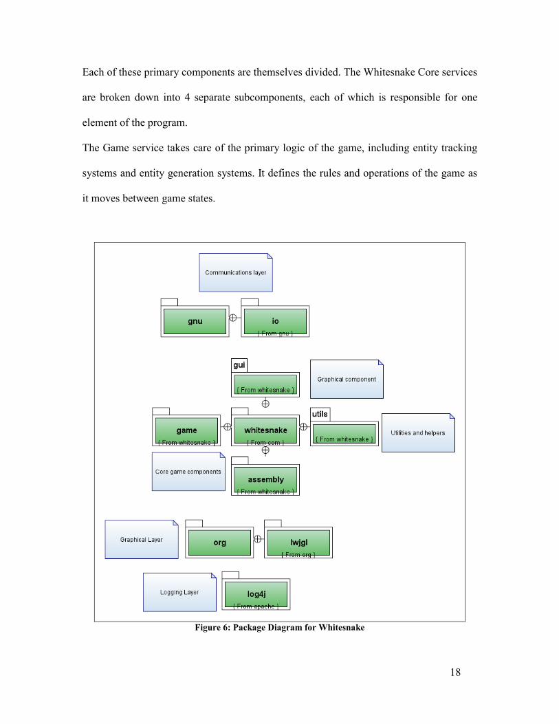
Each of these primary components are themselves divided. The Whitesnake Core services
are broken down into 4 separate subcomponents, each of which is responsible for one
element of the program.
The Game service takes care of the primary logic of the game, including entity tracking
systems and entity generation systems. It defines the rules and operations of the game as
it moves between game states.
Figure 6: Package Diagram for Whitesnake

19
The GUI services are in charge of the graphical aspects of the game, taking care of
rendering, texture loading, texture mapping, and other graphical services. The GUI
services communicate extensively with the graphical layer via lwjgl and makes heavy use
of OpenGL native calls to perform its operations.
The Assembly service includes components which communicate with the hardware (in
this case the guitar and the serial port interface). It is a heavily componentized piece of
Whitesnake which can be used standalone to communicate with any serial port interface
and can easily be extended to communicate with any other type of interface. The
assembly layer was used heavily during the development of Whitesnake not only as a
piece of the game but also as a standalone program (dubbed PortReader) for hardware
testing.
The Utilities service rounds out the program by providing a few helper functions which
assisted in the development process.
4.5. Whitesnake Core
The core game logic of Whitesnake operates as a state machine, and uses the state design
pattern to provide for an extensible framework for future expansion. Each and every state
the program may be in, such as the IntroState and the TutorialState implement a common
GamePlayingState interface. GamePlayingStates support several common methods,
play(), update(), draw(), etc., which allow the core game to access and initialize each
state in the same manner.
20
This design allows for rapid development of new game components. A developer can
simply create a new GamePlayingState and encapsulate all game logic within that state,
and then link this state into the game. The design is also a natural extension of most game
architectures, where a player sees the game as a series of distinct but interconnected parts
(the intro, the credits, levels in the game, etc). By using this architecture, it is very simple
to produce a multi-level design, but simply having each level state point to the next in a
linked list structure.
By implementing this pattern, we ensure that Whitesnake can be easily extended in the
future with new game modes, new levels, and other new features.
4.6. Assembly Layer
The Whitesnake Assembly layer is the single point of entry for all communications
between the game and the Whitesnake hardware (in this case a Guitar connecting to a
laptop via USB). It can function as a fully standalone service which provides services
allowing for the reading and writing of data to various interfaces. For Whitesnake, only a
serial port strategy was written for the service in order to communicate effectively with
the guitar.

21
Figure 7: Class Diagram for the Core Game Logic
The architecture makes heavy use of interfaces and abstract classes and methods in order
to provide for a generic service that can be easily expanded to communicate with various
hardware channels. The important components of the service are:
• Port Factory – Utilizing the Factory Method design pattern, the Port Factory is a
factory which produces ports that can be worked with by assembly layer workers. The

22
port factory encapsulates the rather involved process of initializing connections with
data ports and takes the hassle of obtaining valid data port connections away from
future developers.
• Port Worker – Objects implementing the Port Worker interface are used by the
Assembly Layer to perform ‘work’ on data ports. Usually a Port Worker writes or
reads some data from the data port, and generally perform activities that are related to
the communications hardware. Port Workers can be given individual names, and are
initialized by the Assembly Layer. When Port Workers complete their tasks, they
automatically go into an inactive state, at which point the Assembly Layer can
perform cleanup tasks and eventually remove the worker.
• Port Handlers – Serial Port handlers are asynchronous workers that do work
according to events occurring on the Serial Port. While Port Workers perform tasks
every cycle, Port Handlers are able to perform tasks on call, depending on interrupts
thrown by the communications hardware. Port Handlers register themselves to
specific port events, and perform work designated in their particular handleEvent
actions.
As stated, the Assembly Layer is a fully standalone component that can be used on its
own as a separate program. During the development of Whitesnake, it is often the case
that the hardware team required a system to verify that the guitar was sending correct
inputs, while the software team required a system to mock inputs coming from the guitar.
The Assembly Layer components were used as standalone systems to perform both these
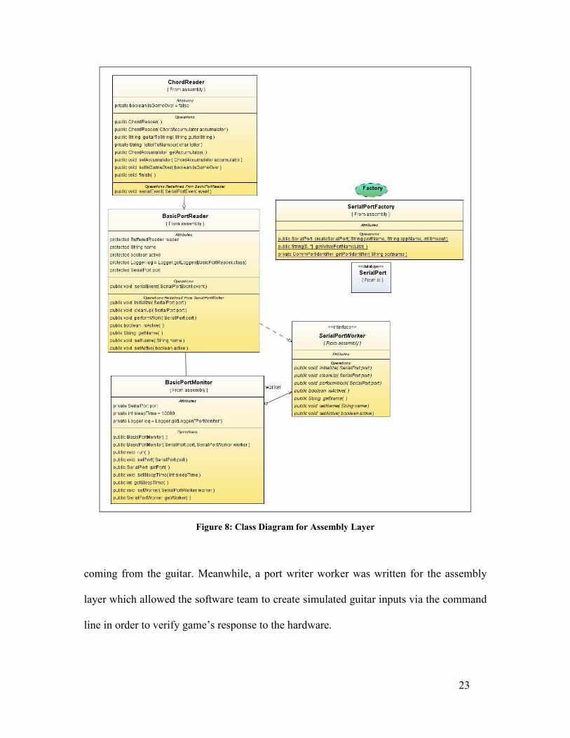
tasks. Packaged as a standalone program called ‘Port Reader’, the Assembly Layer was
disconnected from the rest of the game and used by the hardware team to check inputs
23
Figure 8: Class Diagram for Assembly Layer
coming from the guitar. Meanwhile, a port writer worker was written for the assembly
layer which allowed the software team to create simulated guitar inputs via the command
line in order to verify game’s response to the hardware.

24
This allowed development on hardware and software to proceed synchronously and also
allowed the two teams to test their components extensively without the actual presence of
the other component. This proved to be highly useful in a project with such heavy time
constraints as it allowed for rapid integration of the two components at the end of
development with minimal interfacing issues.
4.7. Graphical Layer
The Graphical Layer of Whitesnake consists of systems to load and map textures and
display them on screen. The heart of the Graphical Layer is the TextureLoader and Entity
classes. These classes form the backbone of the Whitesnake graphical system.
TextureLoader is a generic interface which may be subclassed by various
implementations in order to provide operations that assist in the loading of art assets from
file into memory where they can be manipulated. The Whitesnake texture loader reads
files and loads art assets into memory via a buffered stream. It is then able to process
image files and produce many individual textures from a single file. The texture loader is
also able to generate a series of animation textures when provided with an animated
texture set, by processing the image via the coordinates supplied to it by code. The
texture loader has the additional capability of being able to handle textures of various
color depths, including 24 bit and 32 bit color textures.
The Entity class is the parent class of all displayable objects in the system. Entities are
given a rotation, a position, and a speed, and can render themselves according to these

25
parameters. When the Whitesnake timer begins operation, Entities can self update
according to the speed given to them and interpolate their movements to produce smooth,
continuous motion. The rotation value allowed entities to rotate about their axis by a
speed defined in radians
AnimatedEntity is a subclass of Entity, which provides the additional property of
allowing an Entity to change its appearance (mapped texture) as time passes. By
progressively moving through various frames of animation in a single animated texture,
animated entities give the impression that they are changing with respect to time. These
entities may be used to produce effects such as fire and explosions.
By extending these three core components of the graphical layer, we can rapidly create
new objects and new graphical features to the game.
4.8. Logging with Log4J
It is often necessary or desirable to produce a textual record of events occurring within a
software system during runtime for both debugging purposes as well as to monitor
system behaviour. Project Whitesnake uses the Apache Foundation log4j logging API as
the core logging component of the system.
Log4j was selected because it offers many advantages over logging via standard out,
including the ability to enable logging at runtime without requiring a recompilation of the
program and the modification of the application binary.

26
Log4j allows us to include an external properties file which is loaded at runtime to
control the level of logging, this properties file offers extremely fine grained control over
the level of logging required, allowing us to turn logging on and off completely, specify
logging for specific components only, as well as specifying logging at a specific level
(such as trace, debug, info, or error).
Figure 9: Entity Components of the Graphical Layer

27
This logging component also allows us to specify the destination of the logging output,
allowing us to produce physical logs as well as runtime logs to the console, or even to a
database. Log4j was also selected due to its performance, often faster than simple outputs
to standard out.
With this logging component, we are able to distribute the program binary with all
logging disabled, and, in the event that an error has occurred, modify a simple properties
file which will allow full debug logs to be produced and written to any number of data
sources, assisting us with troubleshooting.
log4j.appender.stdout = org.apache.log4j.ConsoleAppender
log4j.appender.stdout.layout = org.apache.log4j.PatternLayout
log4j.appender.stdout.layout.ConversionPattern = %dHH:mm:ss
[%t] %p %c %x - %m%n
log4j.appender.debugappender = org.apache.log4j.ConsoleAppender
log4j.appender.debugappender.layout =
org.apache.log4j.PatternLayout
log4j.appender.debugappender.layout.ConversionPattern =
%dHH:mm:ss [%t] %p %c %x - %m%n
log4j.rootLogger = ERROR,debugappender
log4j.logger.com.whitesnake.game.ChordComparator=TRACE,stdout
log4j.logger.com.whitesnake.gui.states = INFO,stdout
An example of a log4j properties file is provided above. The technical details of these
properties file is beyond the scope of this report, but can be found at the site of the
Apache Software Foundation page for log4j. It is important to note that with a few simple
lines of text we are able to enable logging to a specific component of the software (in this
case to ChordComparator and all entities in the ‘states’ package).

28
5. Discussion
During the course of Project Whitesnake some of the original designs and ideas were
changed for predicted and unpredicted reasons.
It was predicted that while String 1 was high and touching a fret with another string on it,
the other string would then be at 5V. This is only a problem if the string is on a
microcontroller pin with an open drain which would sink all of the current. Sinking all
the current has many damaging effects; it is basically a short circuit. A short like this
could damage the microcontroller pins, if not the whole chip. The high current on the
strings would make them heat up, potentially breaking. Heated strings would burn the
user, and could cause even greater injury if they were to snap. The high current demand
would be supplied by the USB port of the computer, and could end up damaging the USB
port of the computer. In order to prevent this from happening, all the pins attached to
strings were set to high impedance inputs, and when a string was set high, the pin would
be changed to an output and then back to an input again once all the frets were read.
In order to make this safe for people to use, some research was done to find the current
needed to harm a human. This was suggested to be about 10mA. While someone plays
the guitar their fingers could get sweaty, causing the resistance of their body to drop
significantly. The current was limited to 1mA to prevent any shocks, or even tingling
sensations. This is just a precaution, because the user does not have access to anything
at the ground plane (0V) while playing the instrument.

29
During the testing of Project Whitesnake it was realized that when a string was energized,
it would conduct along a fret to any other string touching that fret and then to any other
fret that the string touched. This was a problem that was not predicted. In order to make
the prototype work in the limited time left, the frets were covered by a non-conductive
material, and fret-board was covered with aluminum tape. Copper would have been
preferred but it was not available at the time. The aluminum tape was electrically
connected to the fret in front of it. This then changed the way the instrument was played.
When a guitar string is played, it resonates between the bridge at the bottom of the guitar
and the fret closest to the bridge; therefore the string only needs to touch that fret. In the
case of the Project Whitesnake guitar the string needed to touch the fret-board in order
for the computer to detect it. This made the guitar more difficult to play, as the guitar
strings needed to be pressed far further than is usually necessary. Due to this, it was
found that the best way to play was while wearing tight-fitting gloves, which allowed the
strings to be pressed down harder, without hurting the user’s fingers as much. This,
unfortunately made it more cumbersome to play, but for the proof of concept, it was
adequate.
While debugging the prototype some unusual and unexpected results were showing up on
the computer. The Microcontroller was sending the wrong information to the computer.
It would read the first fret being pressed on any string think that all the string being
pressed was being pressed to that fret. After many hours of debugging the code, it turned
out to be a physical issue that was never even considered by any member of the team.
While pressing a string set to 5V the players hand would be raised to approximately
30
2.5V. This would then register on any other string being pressed by the user. This
voltage, although low, was high enough to register on the microcontroller as a high.
After attaching a grounded wire to the user's hand and a static strap, the voltage was still
present. The solution to this problem was to wear a non-conductive glove while playing.
This would make the instrument a little harder to play, but was only a temporary solution.
6. Conclusions
This project confirmed that the concept of a computer based musical instrument
instruction system was feasible and affordable. With a total cost of the prototype of under
$250 the system could easily be mass produced very inexpensively. The guitar system
that was created served as a proof of concept. This concept could easily be extended to
other stringed and fretted instruments. With the inclusion of other sensors, such as
pressure sensors, the concept could be extended to woodwind and other instruments.
7. Recommendations The Project Whitesnake Prototype worked well enough to win second place in the IEEE
awards, but it could still be improved on. The aluminum tape on the fret-board and the
non-conductive tape on the frets make the guitar hard to play. To avoid this, the best
solution would be to remove all the frets, electrically separate them into six pieces. This
would ensure the strings don't accidentally conduct. Wires connected to all six sections of
the fret would be wired through diodes to the multiplexers. The circuitry controlling the
multiplexing or PIC does not need to be changed at all, just the fret-board of the guitar.
With more time and tools this could have been done

31
.
8. List of References
[1] C18 Compiler, Available through Microchip at: http://www.microchip.com/stellent/idcplg?IdcService=SS_GET_PAGE&nodeId=1406&dDocName=en010014 [2] Microchip USB Demo software, available through Microchip at: http://www.microchip.com/stellent/idcplg?IdcService=SS_GET_PAGE&nodeId=2651¶m=en534494 [3] Microchip PIC 18F4455 Data sheet, available through Microchip at: http://www.microchip.com/stellent/idcplg?IdcService=SS_GET_PAGE&nodeId=1335&dDocName=en010293
9. Glossary and List of Symbols API (Application Programming Interface): A set of declarations of the functions that an operating system, library, or service provides to support requests made by computer programs. Chord: A combination of three or more notes played simultaneously. CDC (Communications Device Class): A class of USB device that is supported natively by many operating systems. The operating system sees a CDC device as a standard serial port. Fret: A strip of raised metal inserted into the fretboard of a guitar. Pressing the string against a fret reduces the vibrating length of the guitar string. Head: The head of a guitar is located at the end of the neck. The tuning pegs are mounted on the head. Fretboard: A strip of wood on the neck of the guitar facing the strings. Frets are mounted in the fretboard. Log4J: A library developed by the Apache Software Foundation to provide for flexible and portable logging for Java programs. LWJGL (Light Weight Java Game Library): Provides developers access to high performance cross platform libraries such as OpenGL and OpenAL allowing for state of the art 3D games and 3D sound.

32
PIC: A family of microcontroller made by Microchip Technology. The name PIC initially referred to "Programmable Interface Controller”, but was renamed to "Programmable Intelligent Computer". %eck: The neck of a guitar is the long narrow section that the strings stretch out over. The fretboard is mounted on top of the neck. OpenGL (Open Graphics Library): A standard specification defining a cross-language cross-platform API for writing applications that produce 2D and 3D computer graphics. RX-TX: A native library to provide serial and parallel communication for the Java toolkit. Tuning Peg: On a guitar the tuning pegs control the tension of the strings, thus controlling the pitch of each sting. UML (Unified Modeling Language): An object modeling and specification language using software engineering. Whitesnake: A hard rock band formed in 1977. Primarily active in the 1980s, Whitesnake had several chart topping songs including the 1982 hit “Here I Go Again”.