Embed Size (px)
Citation preview
Project Report Supplemental Information
Project No. CM-138-12-1
AcuTech Consulting Group1919 Gallows Road, Suite 900 | Vienna, VA 22182
CD Armstrong; BA Fuller; DB Williams

Table of ContentsQualitative Risk Analysis............................................................................................................ 1
Qualitative Risk Analysis (Process Hazard Analysis) Overview .............................................. 1
PHA Methodology .................................................................................................................. 2
Worksheet Entries............................................................................................................... 4
Guidewords......................................................................................................................... 5
Parameters ......................................................................................................................... 5
Deviations ........................................................................................................................... 5
Causes................................................................................................................................... 5
Consequences.................................................................................................................... 5
Safeguards ......................................................................................................................... 6
Severity and Likelihood Ratings .......................................................................................... 6
Results ................................................................................................................................... 9
References ...............................................................................................................................11
Appendix A – HAZOP Worksheets............................................................................................14
FIGURE 1: RISK RANKING MATRIX ........................................................................................................... 9
TABLE 1: QUALITATIVE RISK ASSESSMENT STUDY TEAM MEMBERS ............................................... 2TABLE 2: QUALITATIVE HAZARD ANALYSIS (PHA) NODES ................................................................... 3TABLE 3: DEFINITIONS OF SEVERITY ...................................................................................................... 8TABLE 4: DEFINITIONS OF LIKELIHOOD .................................................................................................. 9

Project Report Supplemental Information, CRC Project No. CM-138-12-1 Page | 1
Qualitative Risk AnalysisQualitative Risk Analysis (Process Hazard Analysis) Overview
The study team members were guided through a systematic approach using guidelines set for inStandard Practice for System Safety, MIL-STD-882E, developed by the Department of Defense anda PHA-Pro™ template developed by AcuTech for the review. The review was conducted over twosessions – October 15, 2013 and December 16/17, 2013
The methodology used for the qualitative risk assessment is the Hazard and Operability (HAZOP)technique. HAZOP is a structured means of systematically reviewing the process to identifypotential hazards, understand potential consequences and impacts, evaluate current safeguards,estimate the level of risk, and determine appropriate risk mitigation measures to reduce oreliminate the likelihood or severity of the hazards to a tolerable level of risk. HAZOP is recognizedas an accepted methodology by industries and regulatory agencies worldwide. This includes bothOSHA PSM (29 CFR §1910.119[e]) and EPA RMP (40 CFR Part 68) regulations in the UnitedStates, as well as Seveso II Directive; Control of Major Accident Hazards (COMAH); IEC 61511;ANSI/ISA S84.00.01 internationally. In addition, the American Petroleum Institute (API RP 750and API RP 14J) and the American Institute of Chemical Engineers (Hazard EvaluationProcedures, 2nd Edition) recognize the value of this methodology in analyzing process hazards.
The HAZOP study proceeds sequentially, studying each section of the process included in theproject scope. The process under review is partitioned into “nodes,” where there is a distinctintention for process parameters (for example, a specific intended temperature, pressure, or flowrate, or operation type).
The HAZOP technique is based on the premise that hazards and operability problems stem fromdeviations from design intent. To facilitate the review of each node in a structured manner,guidewords are used to capture the ways in which process parameters can deviate from designintent such as; No, More, Less, Misdirected, Reverse, etc. Other guidewords will be defined andused as necessary. The guidewords are systematically combined with the relevant processparameters to yield deviations (e.g., No Flow, High Temperature, Low Pressure, etc.). For eachdeviation credible causes are developed to define:
Consequences
Safeguards
Risk Level
Recommendation to Mitigate Risk, as deemed necessary
HAZOP is intended to be a team review of the process, hazards, consequences of deviation,safeguards, and need for additional risk reduction. Therefore, to conduct the HAZOP proposedin this task, a team of individuals from CRC and the RA/HA team with knowledge of the processand hazards participated.
Project Report Supplemental Information, CRC Project No. CM-138-12-1 Page | 2
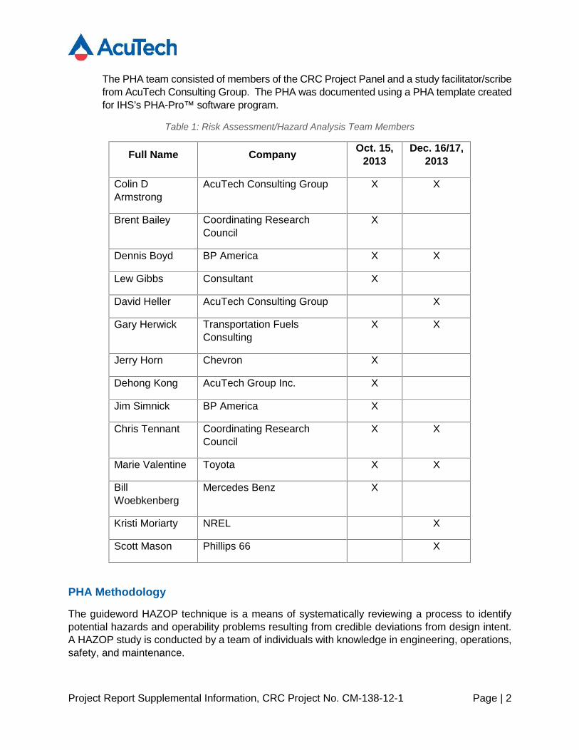
The PHA team consisted of members of the CRC Project Panel and a study facilitator/scribefrom AcuTech Consulting Group. The PHA was documented using a PHA template createdfor IHS’s PHA-Pro™ software program.
Table 1: Risk Assessment/Hazard Analysis Team Members
Full Name Company Oct. 15,2013
Dec. 16/17,2013
Colin DArmstrong
AcuTech Consulting Group X X
Brent Bailey Coordinating ResearchCouncil
X
Dennis Boyd BP America X X
Lew Gibbs Consultant X
David Heller AcuTech Consulting Group X
Gary Herwick Transportation FuelsConsulting
X X
Jerry Horn Chevron X
Dehong Kong AcuTech Group Inc. X
Jim Simnick BP America X
Chris Tennant Coordinating ResearchCouncil
X X
Marie Valentine Toyota X X
BillWoebkenberg
Mercedes Benz X
Kristi Moriarty NREL X
Scott Mason Phillips 66 X
PHA Methodology
The guideword HAZOP technique is a means of systematically reviewing a process to identifypotential hazards and operability problems resulting from credible deviations from design intent.A HAZOP study is conducted by a team of individuals with knowledge in engineering, operations,safety, and maintenance.
Project Report Supplemental Information, CRC Project No. CM-138-12-1 Page | 3
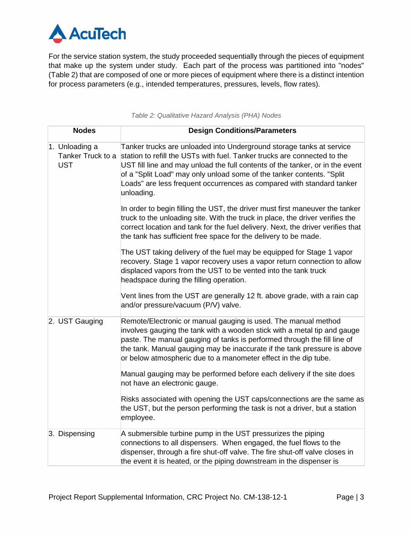
For the service station system, the study proceeded sequentially through the pieces of equipmentthat make up the system under study. Each part of the process was partitioned into "nodes"(Table 2) that are composed of one or more pieces of equipment where there is a distinct intentionfor process parameters (e.g., intended temperatures, pressures, levels, flow rates).
Table 2: Qualitative Hazard Analysis (PHA) Nodes
Nodes Design Conditions/Parameters
1. Unloading aTanker Truck to aUST
Tanker trucks are unloaded into Underground storage tanks at servicestation to refill the USTs with fuel. Tanker trucks are connected to theUST fill line and may unload the full contents of the tanker, or in the eventof a "Split Load" may only unload some of the tanker contents. "SplitLoads” are less frequent occurrences as compared with standard tankerunloading.
In order to begin filling the UST, the driver must first maneuver the tankertruck to the unloading site. With the truck in place, the driver verifies thecorrect location and tank for the fuel delivery. Next, the driver verifies thatthe tank has sufficient free space for the delivery to be made.
The UST taking delivery of the fuel may be equipped for Stage 1 vaporrecovery. Stage 1 vapor recovery uses a vapor return connection to allowdisplaced vapors from the UST to be vented into the tank truckheadspace during the filling operation.
Vent lines from the UST are generally 12 ft. above grade, with a rain capand/or pressure/vacuum (P/V) valve.
2. UST Gauging Remote/Electronic or manual gauging is used. The manual methodinvolves gauging the tank with a wooden stick with a metal tip and gaugepaste. The manual gauging of tanks is performed through the fill line ofthe tank. Manual gauging may be inaccurate if the tank pressure is aboveor below atmospheric due to a manometer effect in the dip tube.
Manual gauging may be performed before each delivery if the site doesnot have an electronic gauge.
Risks associated with opening the UST caps/connections are the same asthe UST, but the person performing the task is not a driver, but a stationemployee.
3. Dispensing A submersible turbine pump in the UST pressurizes the pipingconnections to all dispensers. When engaged, the fuel flows to thedispenser, through a fire shut-off valve. The fire shut-off valve closes inthe event it is heated, or the piping downstream in the dispenser is
Project Report Supplemental Information, CRC Project No. CM-138-12-1 Page | 4
Nodes Design Conditions/Parameters
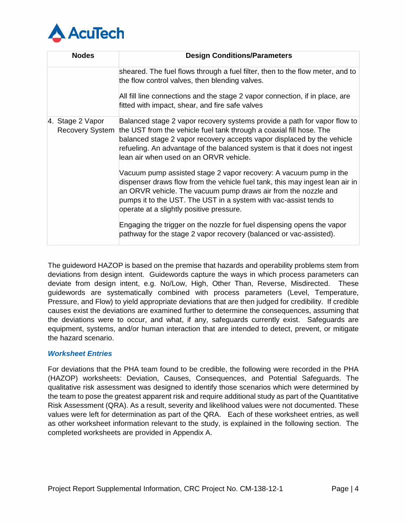
sheared. The fuel flows through a fuel filter, then to the flow meter, and tothe flow control valves, then blending valves.
All fill line connections and the stage 2 vapor connection, if in place, arefitted with impact, shear, and fire safe valves
4. Stage 2 VaporRecovery System
Balanced stage 2 vapor recovery systems provide a path for vapor flow tothe UST from the vehicle fuel tank through a coaxial fill hose. Thebalanced stage 2 vapor recovery accepts vapor displaced by the vehiclerefueling. An advantage of the balanced system is that it does not ingestlean air when used on an ORVR vehicle.
Vacuum pump assisted stage 2 vapor recovery: A vacuum pump in thedispenser draws flow from the vehicle fuel tank, this may ingest lean air inan ORVR vehicle. The vacuum pump draws air from the nozzle andpumps it to the UST. The UST in a system with vac-assist tends tooperate at a slightly positive pressure.
Engaging the trigger on the nozzle for fuel dispensing opens the vaporpathway for the stage 2 vapor recovery (balanced or vac-assisted).
The guideword HAZOP is based on the premise that hazards and operability problems stem fromdeviations from design intent. Guidewords capture the ways in which process parameters candeviate from design intent, e.g. No/Low, High, Other Than, Reverse, Misdirected. Theseguidewords are systematically combined with process parameters (Level, Temperature,Pressure, and Flow) to yield appropriate deviations that are then judged for credibility. If crediblecauses exist the deviations are examined further to determine the consequences, assuming thatthe deviations were to occur, and what, if any, safeguards currently exist. Safeguards areequipment, systems, and/or human interaction that are intended to detect, prevent, or mitigatethe hazard scenario.
Worksheet Entries
For deviations that the PHA team found to be credible, the following were recorded in the PHA(HAZOP) worksheets: Deviation, Causes, Consequences, and Potential Safeguards. Thequalitative risk assessment was designed to identify those scenarios which were determined bythe team to pose the greatest apparent risk and require additional study as part of the QuantitativeRisk Assessment (QRA). As a result, severity and likelihood values were not documented. Thesevalues were left for determination as part of the QRA. Each of these worksheet entries, as wellas other worksheet information relevant to the study, is explained in the following section. Thecompleted worksheets are provided in Appendix A.
Project Report Supplemental Information, CRC Project No. CM-138-12-1 Page | 5
Guidewords
Guidewords are typically used to describe the ways in which process parameters can deviatefrom the design intent. Typical guidewords are No, More, Less, As Well As, Reverse, Part Of,Misdirected, and Other Than. These guidewords are systematically combined with relevantprocess parameters to develop meaningful deviations. The deviations are then judged todetermine whether credible causes of the deviation exist. If credible causes exist, the deviationsare examined further to determine the potential consequences, safeguards, and anyrecommendations. The team used other guidewords when they were useful and provided aclearer understanding of the deviation. Since the guidewords are part of the deviation they havenot been explicitly assigned a worksheet column.
Parameters
A parameter is a physical or chemical property associated with the process, for example,temperature, pressure, level, and flow. However, in the worksheets, only those parametersconsidered relevant for the particular node are usually documented as well as any additionalparameters that the PHA team felt was relevant. Since the parameters are part of the deviationthey have not been explicitly assigned a worksheet column.
Deviations
A "deviation" is an excursion in operating conditions outside the normal range. It is derived bycombining a guideword and a process parameter. For example, the guideword "More" combinedwith the parameter "Temperature" yields the deviation "Higher Temperature". For example “HighLevel” is relevant to a tank or vessel but not to a pipeline. Other deviations were considered ona case-by-case basis as appropriate to the specific node.
Causes
Causes are the specific events or failures that result in a deviation from design intent for a processparameter. For example, "No Flow" may be caused by "pump failure". Detailed root causes (forexample, "pump not turned on due to operator error", or "coupling failure due to excessivevibration") are sometimes listed if this is necessary to determine the consequences or safeguards.General types of causes include equipment failure, human error, and external events. Equipmentfailures are flaws in the equipment design or fabrication that result in predictable failures, wherethe predictability is formed by the history of the equipment in its given service and environment.Human errors include errors of both omission and commission. External events include bothnaturally occurring events (e.g., weather induced events), man-made events (e.g., transportationrelated events), and utility failures (e.g. loss of electrical power) that occur outside the processbeing studied but have an impact on the process. In general, causes were only considered fromwithin the node under study. All credible causes were listed for the deviation under consideration.The team then reviewed the consequences and safeguards for each cause as a separatescenario.
Consequences
The consequences are stated in short, numbered sentences to document each of the potentialhazards or operability problems that could result directly from the Cause, starting with the most

Project Report Supplemental Information, CRC Project No. CM-138-12-1 Page | 6
immediate and followed by subsequent events that result from the initial problems to the worstlikely outcome. The consequences considered credible in the study must fall within the definedobjectives of the PHA. For example:
Deviation: Low/No Flow
Cause: Manual valve in pump discharge closed
Consequences:
loss of flow to column (operability issue)
deadhead pump resulting in seal damage and
- release of flammable liquid to area
- possible fire from ignition of leak
- potential personnel injury and equipment damage
Consequences should be followed beyond the node under consideration to the furthestreasonable extent that problems may arise, both upstream and downstream, so that the hazardsare fully realized. For example, if High Level is being considered as a deviation for a flammablehydrocarbon storage tank, the consequences of "possible overfilling and fire" should bedocumented. This may assume that several protection devices may fail, if realistic. If this is notassumed the hazard of overfilling may be overlooked and not documented.
Safeguards
All existing measures that detect or warn of a cause of a deviation or consequence, prevent acause or consequence, or mitigate the effects of a consequence should be entered in this column.This includes hardware, software, and certain procedural/administrative safeguards. Forexample, written checklists to reduce the risk of human error, a flammable gas detection systemwith alarms, or a pressure relief valve are all safeguards if they are available and reliable.Safeguards must be fully functional, well-maintained, and applicable to the scenario for whichthey are credited. Safeguards were identified for all hazard scenarios i.e. those involving safety,health, property, downtime, or environment-related consequences.
Severity and Likelihood Ratings
Hazard scenarios identified in the PHA were rated on the severity of the consequences and thelikelihood of the scenario occurring, in accordance with a PHA Risk Matrix and associated tables.The risk matrix utilized was based on severity and likelihood definitions from MIL-STD-882E,Standard Practice for System Safety. The consequence severity was rated regardless of thelikelihood and, in general, assumed the failure of all safeguards. First, a four-level Order-of-Magnitude scoring system was used to rank Impact Severity.
Table 3 provides the definitions of Severity used in the study.
Project Report Supplemental Information, CRC Project No. CM-138-12-1 Page | 7
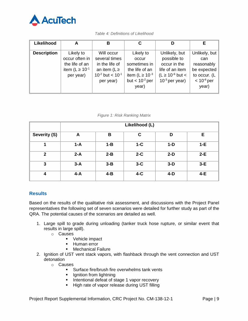
The overall Likelihood of the scenario is based on the sum of 1) the likelihood of the initiatingcause and 2) the likelihood of failure of the identified safeguards to prevent the potential worst-case consequences. Five levels of potential likelihood were utilized.

Project Report Supplemental Information, CRC Project No. CM-138-12-1 Page | 8
Table 4 presents definitions of the five likelihood categories.
A qualitative Risk Ranking Matrix was used to assign a risk level to the hazard scenarios, basedon the scenario severity and likelihood. The Risk Ranking Matrix has risk levels ranging from 1(highest risk) to 4 (lowest risk). The risk levels help the team determine the need for additionalrecommendations and assist in prioritizing any recommendations made. The risk values are anumerical distribution across a pre-selected number of risk values, and not a mathematicalcalculation. The qualitative Risk Ranking/Recommendation Prioritization Matrix is shown in Figure1.
Table 3: Definitions of Severity
Severity Level Definition
1 Could result in one or more of the following: death,permanent total disability, irreversible significantenvironmental impact, or monetary loss equal to orexceeding $10M
2 Could result in one or more of the following: permanentpartial disability, injuries or occupational illness that mayresult in hospitalization of at least three personnel, reversiblesignificant environmental impact, or monetary loss equal toor exceeding $1M but less than $10M
3 Could result in one or more of the following: injury oroccupational illness resulting in one or more lost workday(s), reversible moderate environmental impact, ormonetary loss equal to or exceeding $100K but less than$1M
4 Could result in one or more of the following: injury oroccupational illness not resulting in a lost work day, minimalenvironmental impact, or monetary loss less than $100K
Project Report Supplemental Information, CRC Project No. CM-138-12-1 Page | 9
Table 4: Definitions of Likelihood
Likelihood A B C D E
Description Likely tooccur often inthe life of anitem (L ≥ 10-1
per year)
Will occurseveral timesin the life ofan item (L ≥
10-2 but < 10-1
per year)
Likely tooccur
sometimes inthe life of anitem (L ≥ 10 -3
but < 10-2 peryear)
Unlikely, butpossible tooccur in the
life of an item(L ≥ 10-6 but <10-3 per year)
Unlikely, butcan
reasonablybe expectedto occur. (L< 10-6 per
year)
Figure 1: Risk Ranking Matrix
Likelihood (L)
Severity (S) A B C D E
1 1-A 1-B 1-C 1-D 1-E
2 2-A 2-B 2-C 2-D 2-E
3 3-A 3-B 3-C 3-D 3-E
4 4-A 4-B 4-C 4-D 4-E
Results
Based on the results of the qualitative risk assessment, and discussions with the Project Panelrepresentatives the following set of seven scenarios were detailed for further study as part of theQRA. The potential causes of the scenarios are detailed as well.
1. Large spill to grade during unloading (tanker truck hose rupture, or similar event thatresults in large spill).
o Causes Vehicle impact Human error Mechanical Failure
2. Ignition of UST vent stack vapors, with flashback through the vent connection and USTdetonation
o Causes Surface fire/brush fire overwhelms tank vents Ignition from lightning Intentional defeat of stage 1 vapor recovery High rate of vapor release during UST filling
Project Report Supplemental Information, CRC Project No. CM-138-12-1 Page | 10
3. Ignition of vapors vented at grade in UST area, with flashback and UST detonationo Causes
Human Error Venting of vapors from UST at grade (loose stage 1 connection or
dry break propped open) Ignition by static Ignition by vehicle
4. Direct Ignition of UST headspaceo Causes
Ignition by electrical malfunction5. Uncontrolled spill of fuel to grade in the dispensing area
o Causes Human Error Mechanical Failure
6. Nozzle fire with flashback potentially into the gas tank headspace if flammableo Causes
Static Ignition Human Error creating ignition source
7. Detonation of vapors in an AST tank associated with CA tank pressure managementsystems (consider in conjunction with UST detonation consequences)
o Causes UST Detonation Scenarios described in items 2-4.
A Risk analysis / Hazard Assessment of High Ethanol ContentFuels at Service Stations, CRC Project No. CM-138-12-1 Page | 11
References
[1] U.S Department of Energy, "Handbook for Handling, Storing, and Dispensing E85 and other Ethanol-Gasoline Blends," 2013.
[2] National Fire Protection Association, "Fires at U.S. Service Stations," NFPA, Quincy, MA, 2011.
[3] Center for Chemical Process Safety (CCPS), American Institute of Chemical Engineers (AIChE),Guidelines for Chemical Process Quantitative Risk Analysis – 2nd Edition, New York, NY, 2000.
[4] S. Reddy, "Mathematical Prediction of Flammability of Ethanol-Containing Fuels," Coordinating ResearchCouncil, Alpharetta, GA, 2011.
[5] Center for Chemical Process Safety, Guidelines for Developing Quantitative Safety Risk Criteria, 2009.
[6] American Petroleum Institute - API, "Recommended Practice 2003 - Protection Against Ignitions Arisingout of Static, Lightning, and Stray Current," 1998.
[7] CENELEC, "Electrostatics - Code of practice for the avoidance of hazards due to static electricity - CLC/TR50404," 2003.
[8] NFPA, "NFPA 77 - Recommended Practice on Static Electricity," 2007.
[9] U. K. H. B. H. von Pidoll, "Avoidance of electrostatic hazards during refueling of motorcars," Journal ofElectrostatics, Vols. 40-41, pp. 523-528, 1997.
[10] J. Paasi, R. Lahtinen, T. Kalliohaka and M. Kyto, "Delivery of Biofuels - Project Biojakelu, VTT-R-07059-08/GB," VTT Technical Research Center, Tempere, Finland, 2009.
[11] K. &. G. Paasi, "Chargeablity of Ethanol-Petro Biofuels," Journal Electrostatics, vol. 67, pp. 247-250, 2009.
[12] Resources Safety Division of the Department of Mines & Petroleum (DMP) - Government of WesternAustralia, "Incident investigation Report - Fuel tanker fire at Maddington 15 May 2009," DMP, WesternAustralia, 2011.
[13] Australian Standard AS/NZS 1020: 1995, "The control of undesirable static electricity," 1995.
[14] Petroleum Equipment Institute (PEI), "Fires at Refueling Sites That Appear to Be Static Related -Summary," PEI, 2010.
[15] H. Persson, P. Bremer, L. Rosell, K. Arrhenius and K. Lindstrom, "Fuel Vapour Compositions andFlammability Properties of E85," SP Technical Research Institute, 2008.
A Risk analysis / Hazard Assessment of High Ethanol ContentFuels at Service Stations, CRC Project No. CM-138-12-1 Page | 12
[16] American Petroleum Institute, "API Standard 2000 - "Venting Atmospherice and Low-Pressure StorageTanks; Nonrefrigerated and Refrigerated"," API, 1998 5th edition.
[17] T. H. Michael Davies, "Protect Your Process with the Proper Flame Arresters," Chemical EngineeringProgress, pp. 16-22, December 2013.
[18] Soutwest Research Institute, "LITERATURE REVIEW OF THE USEFULNESS AND EFFICACY OFFLAME ARRESTERS AND Pressure VACUUM VALVES WITH GASOLINE-ETHANOL BLENDS".
[19] Swedish Petroleum Institute, "Recommendations on the Handling of E85," June 2010.
[20] Swedish Authority for Civil Protection and Preparedness, "Handling of Flammable Gases and Liquids atService Stations," 2008.
[21] UK Association for Petroleum and Explosives Administration (APEA), "Guidance on Storage andDispensing of High Blend Ethanol Fuels Including E85 at Filling Stations".
[22] OSHA de (German OSHA), "Requirements for Fuels Containing Bioethanol," [Online]. Available:http://lasi.osha.de/de/gfx/publications/lv47_info.htm.
[23] American Petroleum Institute - RP1626, "RP 1626 - Storing and Handling Ethanol and Gasoline-EthanolBlends at Distribution Terminals and Filling Stations".
[24] SP Technical Research Institute of Sweden, "Fuel Vapor Composition and Flammability Properties of E85".
[25] S. Kent, "Tank Explosions: When the Unexpected Strikes," in NEIWPCC, 23rd National Tanks Conference,St. Louis, Missouri, 2012.
[26] Federal Emergency Management Agency, " Handbook of Chemical Hazard Analysis Procedures," 1990.
[27] TNO, " CPR 18E Guidelines for Quantitative Risk Assessment," 1999.
[28] Environmental Protection Agency, "Risk Management Program, Appendix A - References for ConsequenceAnalysis Methods," 1999.
[29] S. Mannan, Lees' Loss Prevention in the Process Industries, Butterworth-Heinemann, 2012.
[30] United States Department of Defense, "MIL-STD-882E: System Safety," Washington D.C., 2012.
[31] State of California Air Resources Board, "Executive Order VR-202-N Healy Phase II Enhanced VaporRecovery (EVR) System Including In-Station Diagnostiv (ISD) Systems," Sacramento, CA, 2011.
[32] C. Jones, "Vehicle Changes for E85 Conversion," in DoE/NREL/EPA Clean Cities Webcast, 2007.
[33] S. S. Grossel, Deflagration and Detonation Arresters, Center for Chemical Process Safety/AIChE, 2002.
A Risk analysis / Hazard Assessment of High Ethanol ContentFuels at Service Stations, CRC Project No. CM-138-12-1 Page | 13
[34] V. E. Clancey, "Diagnostic Features of Explosion Damage," in 6th International Meeting on ForensicScientists, Scotland, 1972.
A Risk analysis / Hazard Assessment of High Ethanol ContentFuels at Service Stations, CRC Project No. CM-138-12-1 Page | 14
Appendix A – HAZOP Worksheets
A Risk analysis / Hazard Assessment of High Ethanol ContentFuels at Service Stations, CRC Project No. CM-138-12-1 Page | 15
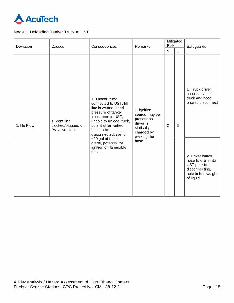
Node 1: Unloading Tanker Truck to UST
Deviation Causes Consequences RemarksMitigatedRisk SafeguardsS L
1. No Flow1. Vent lineblocked/plugged orPV valve closed
1. Tanker truckconnected to UST, fillline is wetted, headpressure of tankertruck open to UST,unable to unload truck,potential for wettedhose to bedisconnected, spill of~20 gal of fuel tograde, potential forignition of flammablepool
1. ignitionsource may bepresent asdriver isstaticallycharged bywalking thehose
2 E
1. Truck driverchecks level intruck and hoseprior to disconnect
2. Driver walkshose to drain intoUST prior todisconnecting,able to feel weightof liquid.
A Risk analysis / Hazard Assessment of High Ethanol ContentFuels at Service Stations, CRC Project No. CM-138-12-1 Page | 16
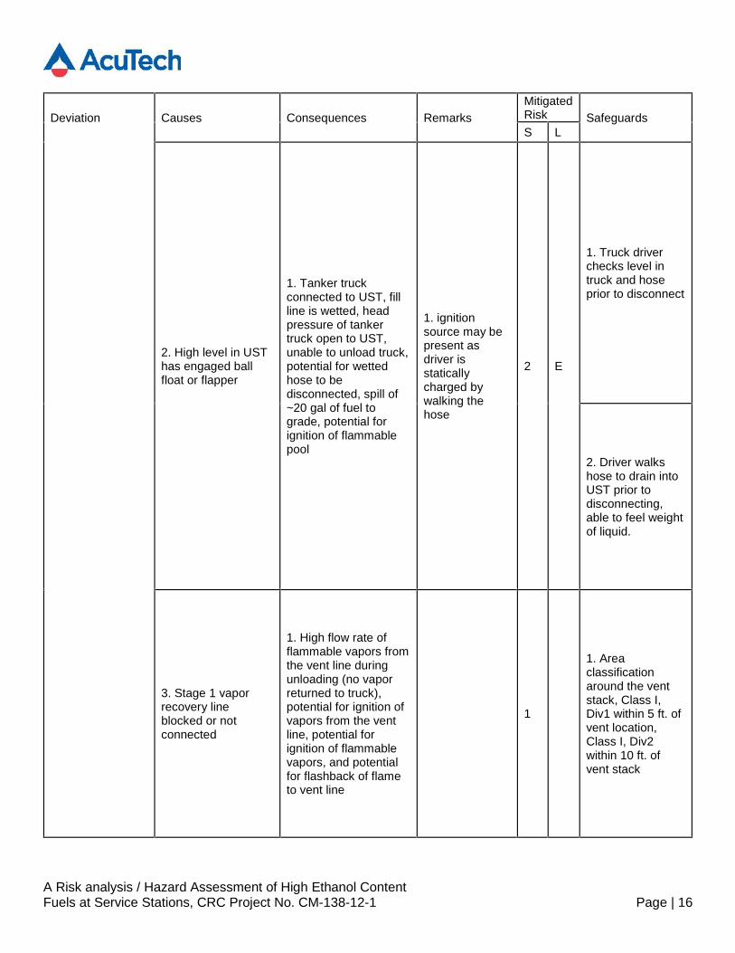
Deviation Causes Consequences RemarksMitigatedRisk SafeguardsS L
2. High level in USThas engaged ballfloat or flapper
1. Tanker truckconnected to UST, fillline is wetted, headpressure of tankertruck open to UST,unable to unload truck,potential for wettedhose to bedisconnected, spill of~20 gal of fuel tograde, potential forignition of flammablepool
1. ignitionsource may bepresent asdriver isstaticallycharged bywalking thehose
2 E
1. Truck driverchecks level intruck and hoseprior to disconnect
2. Driver walkshose to drain intoUST prior todisconnecting,able to feel weightof liquid.
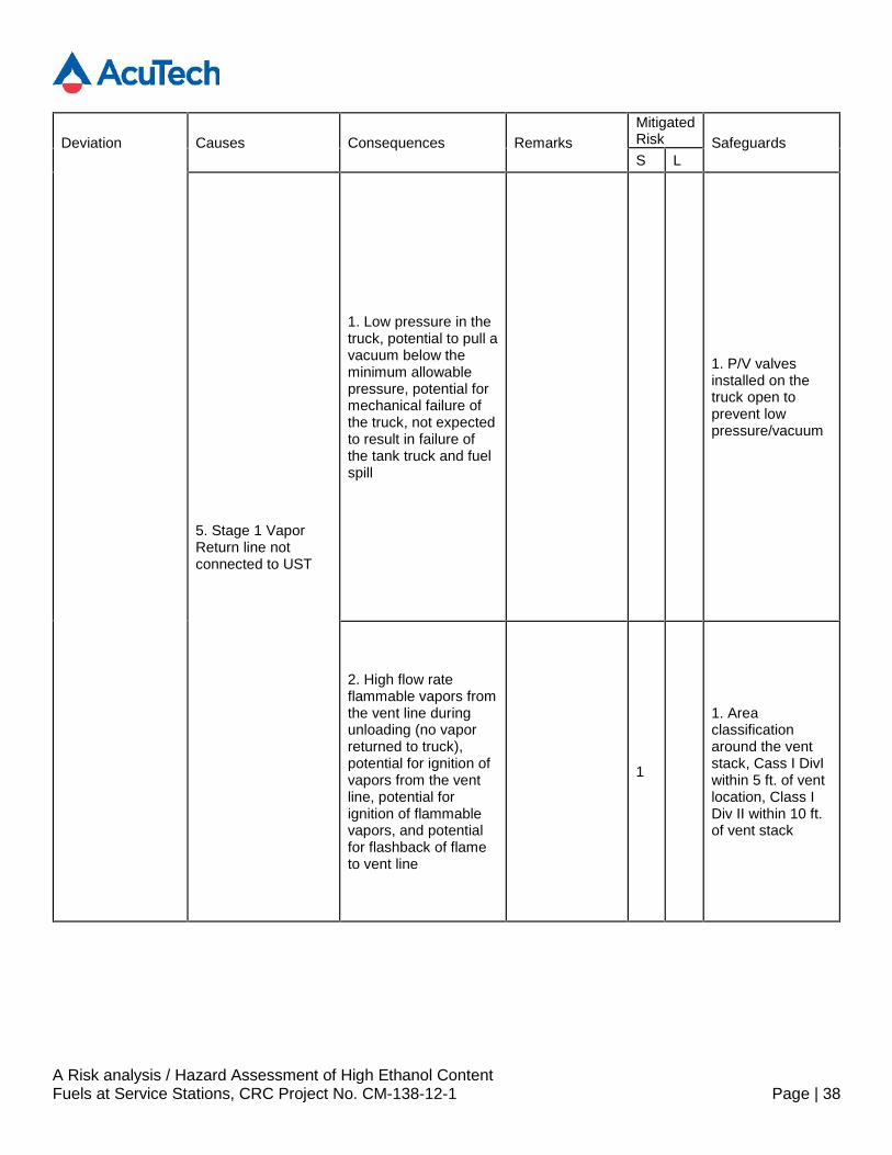
3. Stage 1 vaporrecovery lineblocked or notconnected
1. High flow rate offlammable vapors fromthe vent line duringunloading (no vaporreturned to truck),potential for ignition ofvapors from the ventline, potential forignition of flammablevapors, and potentialfor flashback of flameto vent line
1
1. Areaclassificationaround the ventstack, Class I,Div1 within 5 ft. ofvent location,Class I, Div2within 10 ft. ofvent stack
A Risk analysis / Hazard Assessment of High Ethanol ContentFuels at Service Stations, CRC Project No. CM-138-12-1 Page | 17
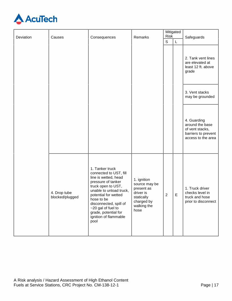
Deviation Causes Consequences RemarksMitigatedRisk SafeguardsS L
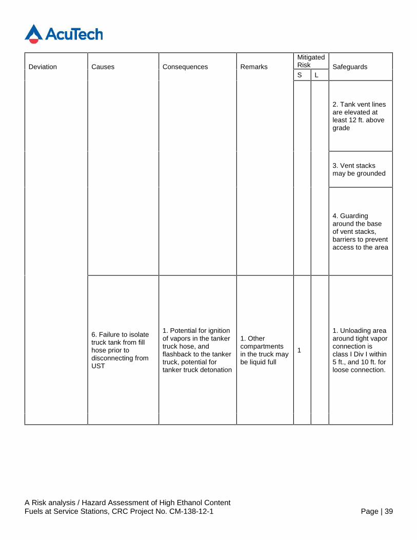
2. Tank vent linesare elevated atleast 12 ft. abovegrade
3. Vent stacksmay be grounded
4. Guardingaround the baseof vent stacks,barriers to preventaccess to the area
4. Drop tubeblocked/plugged
1. Tanker truckconnected to UST, fillline is wetted, headpressure of tankertruck open to UST,unable to unload truck,potential for wettedhose to bedisconnected, spill of~20 gal of fuel tograde, potential forignition of flammablepool
1. ignitionsource may bepresent asdriver isstaticallycharged bywalking thehose
2 E
1. Truck driverchecks level intruck and hoseprior to disconnect
A Risk analysis / Hazard Assessment of High Ethanol ContentFuels at Service Stations, CRC Project No. CM-138-12-1 Page | 18
Deviation Causes Consequences RemarksMitigatedRisk SafeguardsS L
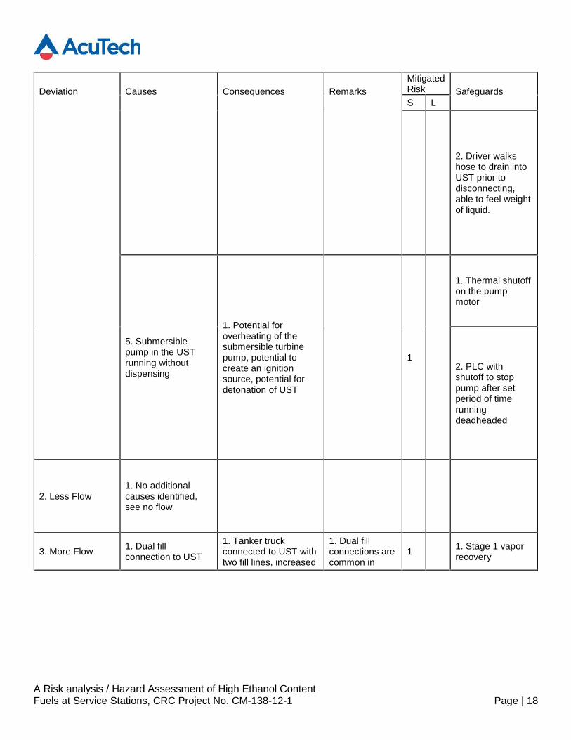
2. Driver walkshose to drain intoUST prior todisconnecting,able to feel weightof liquid.
5. Submersiblepump in the USTrunning withoutdispensing
1. Potential foroverheating of thesubmersible turbinepump, potential tocreate an ignitionsource, potential fordetonation of UST
1
1. Thermal shutoffon the pumpmotor
2. PLC withshutoff to stoppump after setperiod of timerunningdeadheaded
2. Less Flow1. No additionalcauses identified,see no flow
3. More Flow 1. Dual fillconnection to UST
1. Tanker truckconnected to UST withtwo fill lines, increased
1. Dual fillconnections arecommon in
1 1. Stage 1 vaporrecovery
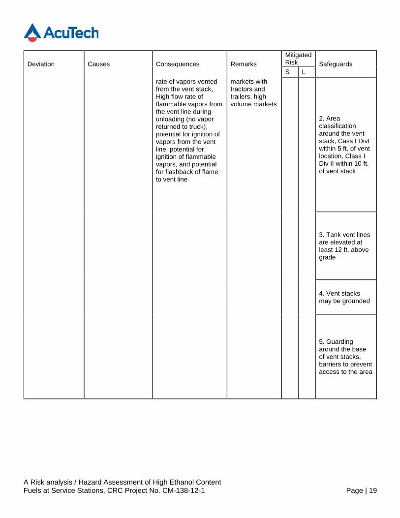
A Risk analysis / Hazard Assessment of High Ethanol ContentFuels at Service Stations, CRC Project No. CM-138-12-1 Page | 19
Deviation Causes Consequences RemarksMitigatedRisk SafeguardsS L
rate of vapors ventedfrom the vent stack,High flow rate offlammable vapors fromthe vent line duringunloading (no vaporreturned to truck),potential for ignition ofvapors from the ventline, potential forignition of flammablevapors, and potentialfor flashback of flameto vent line
markets withtractors andtrailers, highvolume markets
2. Areaclassificationaround the ventstack, Cass I DivIwithin 5 ft. of ventlocation, Class IDiv II within 10 ft.of vent stack
3. Tank vent linesare elevated atleast 12 ft. abovegrade
4. Vent stacksmay be grounded
5. Guardingaround the baseof vent stacks,barriers to preventaccess to the area
A Risk analysis / Hazard Assessment of High Ethanol ContentFuels at Service Stations, CRC Project No. CM-138-12-1 Page | 20
Deviation Causes Consequences RemarksMitigatedRisk SafeguardsS L
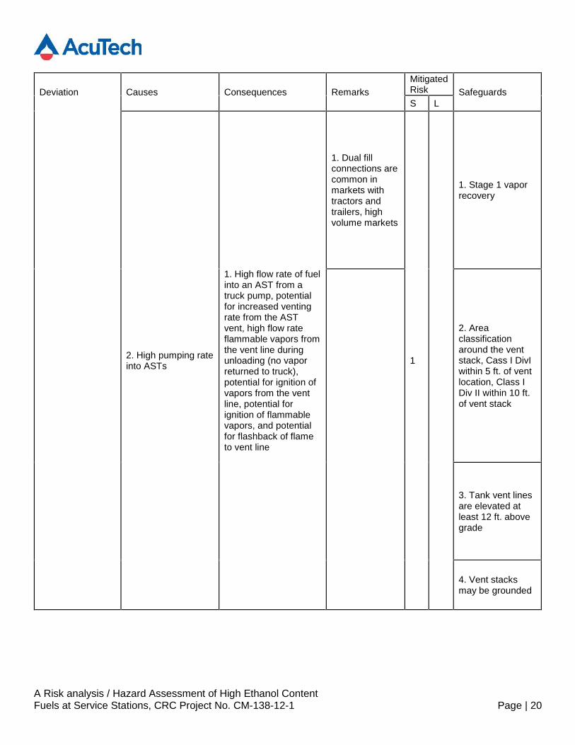
2. High pumping rateinto ASTs
1. High flow rate of fuelinto an AST from atruck pump, potentialfor increased ventingrate from the ASTvent, high flow rateflammable vapors fromthe vent line duringunloading (no vaporreturned to truck),potential for ignition ofvapors from the ventline, potential forignition of flammablevapors, and potentialfor flashback of flameto vent line
1. Dual fillconnections arecommon inmarkets withtractors andtrailers, highvolume markets
1
1. Stage 1 vaporrecovery
2. Areaclassificationaround the ventstack, Cass I DivIwithin 5 ft. of ventlocation, Class IDiv II within 10 ft.of vent stack
3. Tank vent linesare elevated atleast 12 ft. abovegrade
4. Vent stacksmay be grounded

A Risk analysis / Hazard Assessment of High Ethanol ContentFuels at Service Stations, CRC Project No. CM-138-12-1 Page | 21
Deviation Causes Consequences RemarksMitigatedRisk SafeguardsS L
5. Guardingaround the baseof vent stacks,barriers to preventaccess to the area
4. MisdirectedFlow
1. Stage 1 vaporrecovery dry breakconnection proppedopen
1. Dry break vaporconnection is proppedopen, release ofvapors from the tank atgrade level, potentialfor ignition of vaporsfrom the vent line,potential for ignition offlammable vapors, andpotential for flashbackof flame to vent line
1
1. Unloading areaaround tight vaporconnection isclass I Div I within5 ft., and 10 ft. forloose connection.
2. Commonlyoccurs inindustry
2. Safety conesmay be used torestrict entry intothe area
5. Reverse Flow 1. No issuesidentified
6. Other ThanFlow
1. No issuesidentified
A Risk analysis / Hazard Assessment of High Ethanol ContentFuels at Service Stations, CRC Project No. CM-138-12-1 Page | 22
Deviation Causes Consequences RemarksMitigatedRisk SafeguardsS L
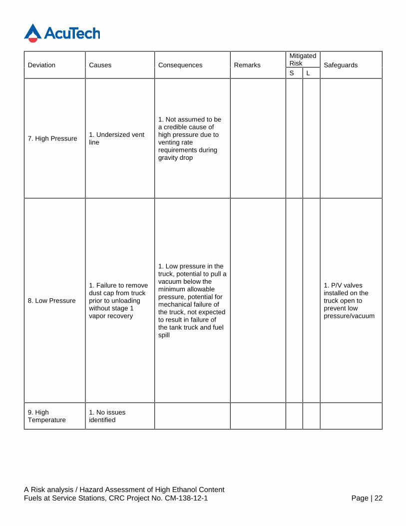
7. High Pressure 1. Undersized ventline
1. Not assumed to bea credible cause ofhigh pressure due toventing raterequirements duringgravity drop
8. Low Pressure
1. Failure to removedust cap from truckprior to unloadingwithout stage 1vapor recovery
1. Low pressure in thetruck, potential to pull avacuum below theminimum allowablepressure, potential formechanical failure ofthe truck, not expectedto result in failure ofthe tank truck and fuelspill
1. P/V valvesinstalled on thetruck open toprevent lowpressure/vacuum
9. HighTemperature
1. No issuesidentified
A Risk analysis / Hazard Assessment of High Ethanol ContentFuels at Service Stations, CRC Project No. CM-138-12-1 Page | 23
Deviation Causes Consequences RemarksMitigatedRisk SafeguardsS L
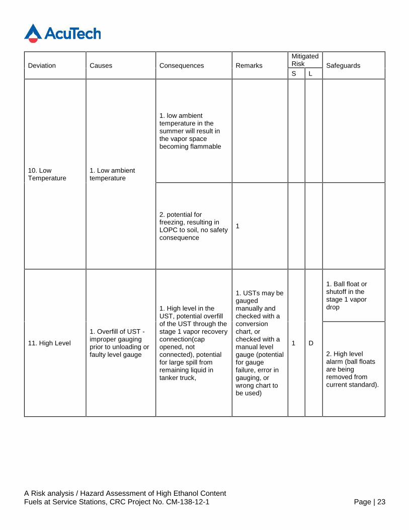
10. LowTemperature
1. Low ambienttemperature
1. low ambienttemperature in thesummer will result inthe vapor spacebecoming flammable
2. potential forfreezing, resulting inLOPC to soil, no safetyconsequence
1
11. High Level
1. Overfill of UST -improper gaugingprior to unloading orfaulty level gauge
1. High level in theUST, potential overfillof the UST through thestage 1 vapor recoveryconnection(capopened, notconnected), potentialfor large spill fromremaining liquid intanker truck,
1. USTs may begaugedmanually andchecked with aconversionchart, orchecked with amanual levelgauge (potentialfor gaugefailure, error ingauging, orwrong chart tobe used)
1 D
1. Ball float orshutoff in thestage 1 vapordrop
2. High levelalarm (ball floatsare beingremoved fromcurrent standard).
A Risk analysis / Hazard Assessment of High Ethanol ContentFuels at Service Stations, CRC Project No. CM-138-12-1 Page | 24
Deviation Causes Consequences RemarksMitigatedRisk SafeguardsS L
3. Shutdown valveactivated by driverwith switchlocated at the endof the truck (DOTrequirement)
4. Driver ispresent within 25ft. of connection(DOTrequirement)
5. Site may begraded to drain toa swale, but this isnot required
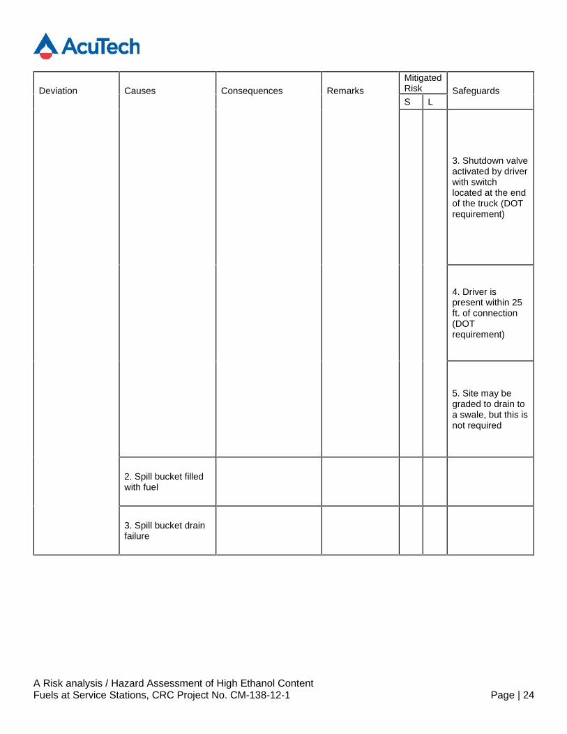
2. Spill bucket filledwith fuel
3. Spill bucket drainfailure
A Risk analysis / Hazard Assessment of High Ethanol ContentFuels at Service Stations, CRC Project No. CM-138-12-1 Page | 25
Deviation Causes Consequences RemarksMitigatedRisk SafeguardsS L
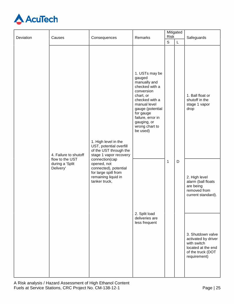
4. Failure to shutoffflow to the USTduring a 'SplitDelivery'
1. High level in theUST, potential overfillof the UST through thestage 1 vapor recoveryconnection(capopened, notconnected), potentialfor large spill fromremaining liquid intanker truck,
1. USTs may begaugedmanually andchecked with aconversionchart, orchecked with amanual levelgauge (potentialfor gaugefailure, error ingauging, orwrong chart tobe used)
1 D
1. Ball float orshutoff in thestage 1 vapordrop
2. Split loaddeliveries areless frequent
2. High levelalarm (ball floatsare beingremoved fromcurrent standard).
3. Shutdown valveactivated by driverwith switchlocated at the endof the truck (DOTrequirement)
A Risk analysis / Hazard Assessment of High Ethanol ContentFuels at Service Stations, CRC Project No. CM-138-12-1 Page | 26
Deviation Causes Consequences RemarksMitigatedRisk SafeguardsS L
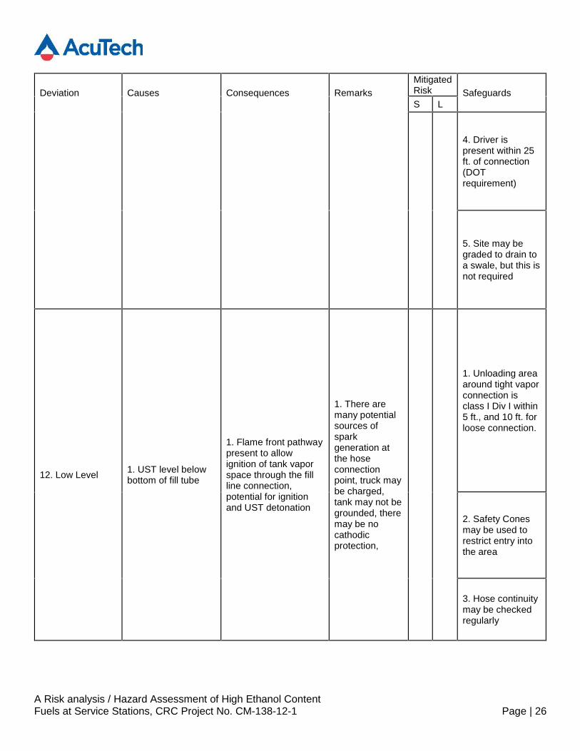
4. Driver ispresent within 25ft. of connection(DOTrequirement)
5. Site may begraded to drain toa swale, but this isnot required
12. Low Level 1. UST level belowbottom of fill tube
1. Flame front pathwaypresent to allowignition of tank vaporspace through the fillline connection,potential for ignitionand UST detonation
1. There aremany potentialsources ofsparkgeneration atthe hoseconnectionpoint, truck maybe charged,tank may not begrounded, theremay be nocathodicprotection,
1. Unloading areaaround tight vaporconnection isclass I Div I within5 ft., and 10 ft. forloose connection.
2. Safety Conesmay be used torestrict entry intothe area
3. Hose continuitymay be checkedregularly
A Risk analysis / Hazard Assessment of High Ethanol ContentFuels at Service Stations, CRC Project No. CM-138-12-1 Page | 27
Deviation Causes Consequences RemarksMitigatedRisk SafeguardsS L
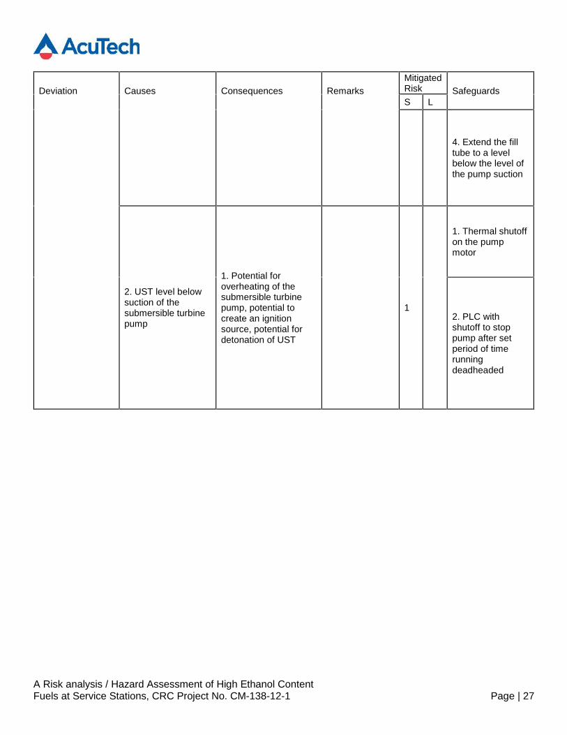
4. Extend the filltube to a levelbelow the level ofthe pump suction
2. UST level belowsuction of thesubmersible turbinepump
1. Potential foroverheating of thesubmersible turbinepump, potential tocreate an ignitionsource, potential fordetonation of UST
1
1. Thermal shutoffon the pumpmotor
2. PLC withshutoff to stoppump after setperiod of timerunningdeadheaded

A Risk analysis / Hazard Assessment of High Ethanol ContentFuels at Service Stations, CRC Project No. CM-138-12-1 Page | 28
Deviation Causes Consequences RemarksMitigatedRisk SafeguardsS L
13. High/LowComposition
1. Connection ofethanol and diesel orconventionalgasoline tank vaporspaces through acommon ventheader
1. Potential to create aflammable atmospherein thediesel/conventionaltank headspace,potential for ignition ofthe headspace(dieselfilling and pumping hasan increased risk ofspark generation dueto static), potentialfire/explosion
1. gaugingpractices in thetank may nottake precautionagainstflammablevapor spaces
1
1. Ethanol anddiesel ventheaders are notinterconnected
2. Diesel UST isconsidered to beClass I Div I
A Risk analysis / Hazard Assessment of High Ethanol ContentFuels at Service Stations, CRC Project No. CM-138-12-1 Page | 29
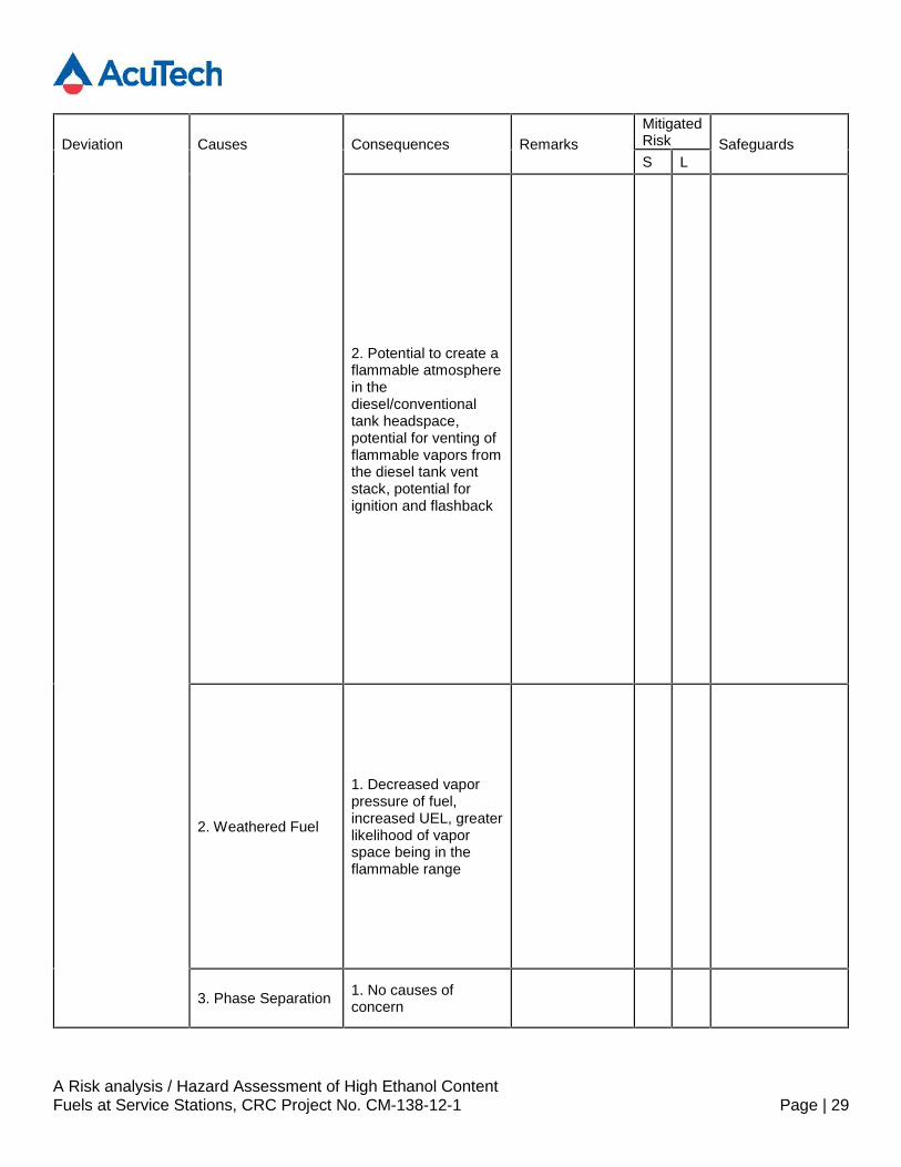
Deviation Causes Consequences RemarksMitigatedRisk SafeguardsS L
2. Potential to create aflammable atmospherein thediesel/conventionaltank headspace,potential for venting offlammable vapors fromthe diesel tank ventstack, potential forignition and flashback
2. Weathered Fuel
1. Decreased vaporpressure of fuel,increased UEL, greaterlikelihood of vaporspace being in theflammable range
3. Phase Separation 1. No causes ofconcern
A Risk analysis / Hazard Assessment of High Ethanol ContentFuels at Service Stations, CRC Project No. CM-138-12-1 Page | 30
Deviation Causes Consequences RemarksMitigatedRisk SafeguardsS L
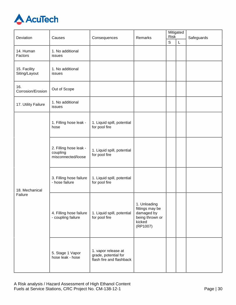
14. HumanFactors
1. No additionalissues
15. FacilitySiting/Layout
1. No additionalissues
16.Corrosion/Erosion Out of Scope
17. Utility Failure 1. No additionalissues
18. MechanicalFailure
1. Filling hose leak -hose
1. Liquid spill, potentialfor pool fire
2. Filling hose leak -couplingmisconnected/loose
1. Liquid spill, potentialfor pool fire
3. Filling hose failure- hose failure
1. Liquid spill, potentialfor pool fire
4. Filling hose failure- coupling failure
1. Liquid spill, potentialfor pool fire
1. Unloadingfittings may bedamaged bybeing thrown orkicked(RP1007)
5. Stage 1 Vaporhose leak - hose
1. vapor release atgrade, potential forflash fire and flashback
A Risk analysis / Hazard Assessment of High Ethanol ContentFuels at Service Stations, CRC Project No. CM-138-12-1 Page | 31
Deviation Causes Consequences RemarksMitigatedRisk SafeguardsS L
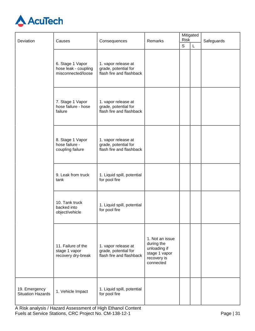
6. Stage 1 Vaporhose leak - couplingmisconnected/loose
1. vapor release atgrade, potential forflash fire and flashback
7. Stage 1 Vaporhose failure - hosefailure
1. vapor release atgrade, potential forflash fire and flashback
8. Stage 1 Vaporhose failure -coupling failure
1. vapor release atgrade, potential forflash fire and flashback
9. Leak from trucktank
1. Liquid spill, potentialfor pool fire
10. Tank truckbacked intoobject/vehicle
1. Liquid spill, potentialfor pool fire
11. Failure of thestage 1 vaporrecovery dry-break
1. vapor release atgrade, potential forflash fire and flashback
1. Not an issueduring theunloading ifstage 1 vaporrecovery isconnected
19. EmergencySituation Hazards 1. Vehicle Impact 1. Liquid spill, potential
for pool fire
A Risk analysis / Hazard Assessment of High Ethanol ContentFuels at Service Stations, CRC Project No. CM-138-12-1 Page | 32
Deviation Causes Consequences RemarksMitigatedRisk SafeguardsS L
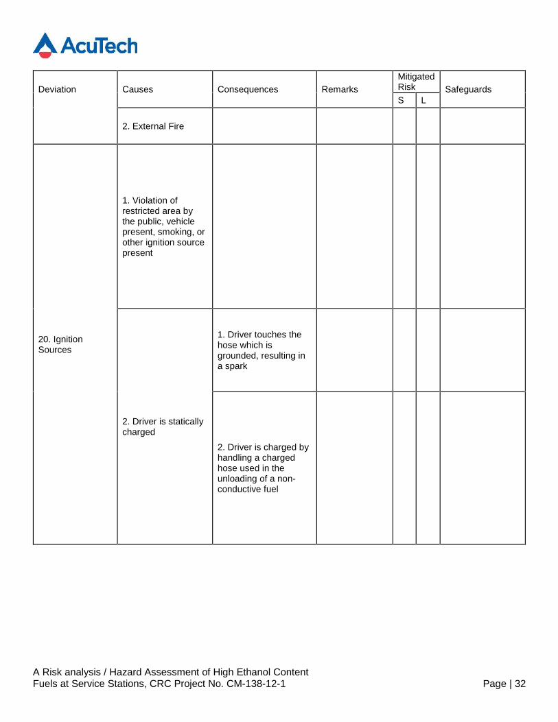
2. External Fire
20. IgnitionSources
1. Violation ofrestricted area bythe public, vehiclepresent, smoking, orother ignition sourcepresent
2. Driver is staticallycharged
1. Driver touches thehose which isgrounded, resulting ina spark
2. Driver is charged byhandling a chargedhose used in theunloading of a non-conductive fuel
A Risk analysis / Hazard Assessment of High Ethanol ContentFuels at Service Stations, CRC Project No. CM-138-12-1 Page | 33
Deviation Causes Consequences RemarksMitigatedRisk SafeguardsS L
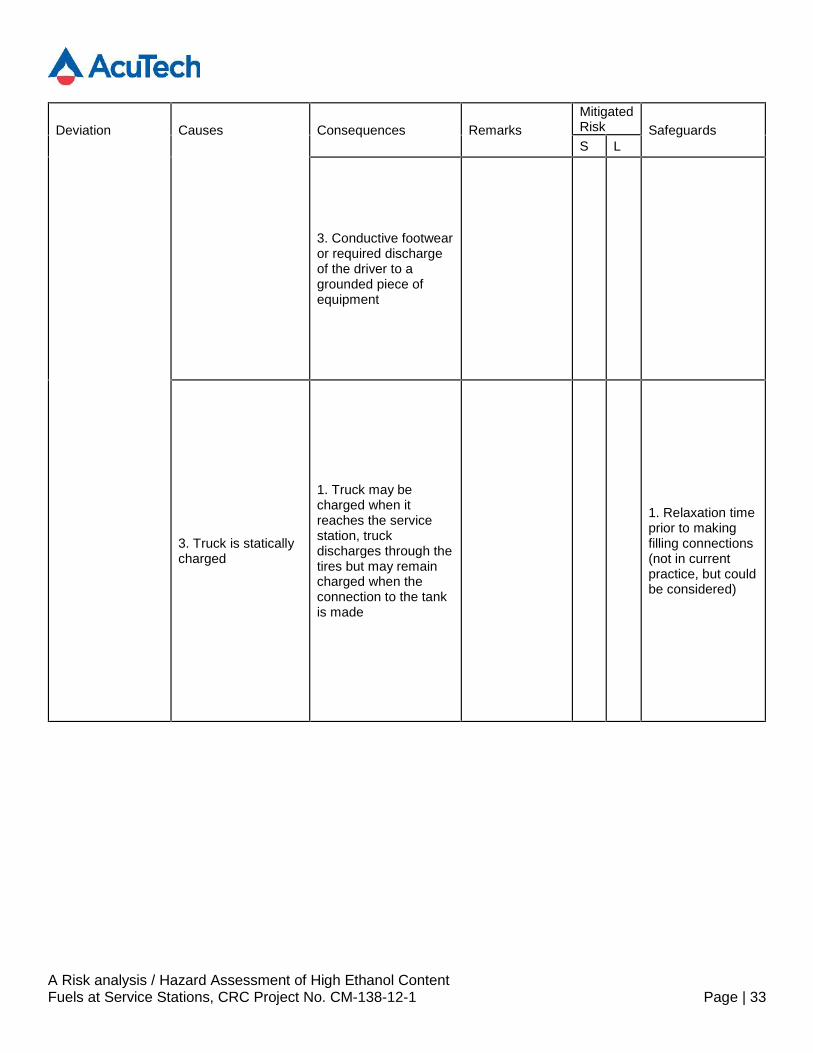
3. Conductive footwearor required dischargeof the driver to agrounded piece ofequipment
3. Truck is staticallycharged
1. Truck may becharged when itreaches the servicestation, truckdischarges through thetires but may remaincharged when theconnection to the tankis made
1. Relaxation timeprior to makingfilling connections(not in currentpractice, but couldbe considered)

A Risk analysis / Hazard Assessment of High Ethanol ContentFuels at Service Stations, CRC Project No. CM-138-12-1 Page | 34
Deviation Causes Consequences RemarksMitigatedRisk SafeguardsS L
4. Nonconductivehose in use
1. Nonconductive hosemoved by the driver orimpacted bywind/debrisaccumulates staticcharge and dischargesto connection
2. Nonconductive hosecharged by use ingasoline service
5. Concrete in theloading area is notconductive
1. Unable to dischargetruck static prior to fillconnection, potentialfor static dischargeupon nozzleconnection
A Risk analysis / Hazard Assessment of High Ethanol ContentFuels at Service Stations, CRC Project No. CM-138-12-1 Page | 35
Deviation Causes Consequences RemarksMitigatedRisk SafeguardsS L
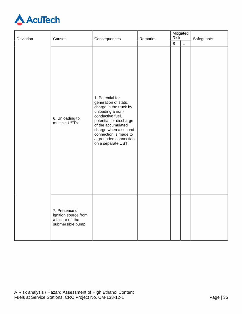
6. Unloading tomultiple USTs
1. Potential forgeneration of staticcharge in the truck byunloading a non-conductive fuel,potential for dischargeof the accumulatedcharge when a secondconnection is made toa grounded connectionon a separate UST
7. Presence ofignition source froma failure of thesubmersible pump
A Risk analysis / Hazard Assessment of High Ethanol ContentFuels at Service Stations, CRC Project No. CM-138-12-1 Page | 36
Deviation Causes Consequences RemarksMitigatedRisk SafeguardsS L
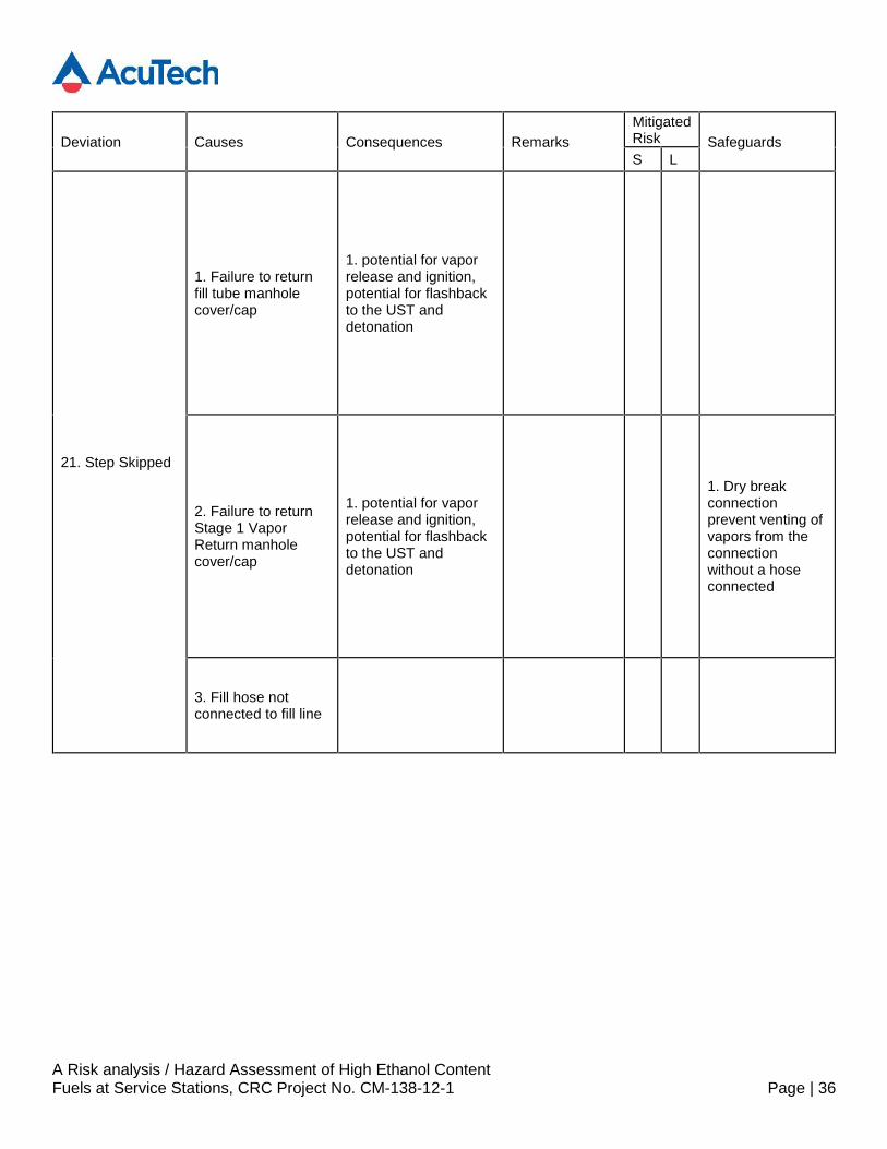
21. Step Skipped
1. Failure to returnfill tube manholecover/cap
1. potential for vaporrelease and ignition,potential for flashbackto the UST anddetonation
2. Failure to returnStage 1 VaporReturn manholecover/cap
1. potential for vaporrelease and ignition,potential for flashbackto the UST anddetonation
1. Dry breakconnectionprevent venting ofvapors from theconnectionwithout a hoseconnected
3. Fill hose notconnected to fill line
A Risk analysis / Hazard Assessment of High Ethanol ContentFuels at Service Stations, CRC Project No. CM-138-12-1 Page | 37
Deviation Causes Consequences RemarksMitigatedRisk SafeguardsS L
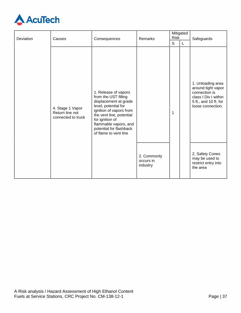
4. Stage 1 VaporReturn line notconnected to truck
1. Release of vaporsfrom the UST fillingdisplacement at gradelevel, potential forignition of vapors fromthe vent line, potentialfor ignition offlammable vapors, andpotential for flashbackof flame to vent line
1
1. Unloading areaaround tight vaporconnection isclass I Div I within5 ft., and 10 ft. forloose connection.
2. Commonlyoccurs inindustry
2. Safety Conesmay be used torestrict entry intothe area
A Risk analysis / Hazard Assessment of High Ethanol ContentFuels at Service Stations, CRC Project No. CM-138-12-1 Page | 38
Deviation Causes Consequences RemarksMitigatedRisk SafeguardsS L
5. Stage 1 VaporReturn line notconnected to UST
1. Low pressure in thetruck, potential to pull avacuum below theminimum allowablepressure, potential formechanical failure ofthe truck, not expectedto result in failure ofthe tank truck and fuelspill
1. P/V valvesinstalled on thetruck open toprevent lowpressure/vacuum
2. High flow rateflammable vapors fromthe vent line duringunloading (no vaporreturned to truck),potential for ignition ofvapors from the ventline, potential forignition of flammablevapors, and potentialfor flashback of flameto vent line
1
1. Areaclassificationaround the ventstack, Cass I DivIwithin 5 ft. of ventlocation, Class IDiv II within 10 ft.of vent stack
A Risk analysis / Hazard Assessment of High Ethanol ContentFuels at Service Stations, CRC Project No. CM-138-12-1 Page | 39
Deviation Causes Consequences RemarksMitigatedRisk SafeguardsS L
2. Tank vent linesare elevated atleast 12 ft. abovegrade
3. Vent stacksmay be grounded
4. Guardingaround the baseof vent stacks,barriers to preventaccess to the area
6. Failure to isolatetruck tank from fillhose prior todisconnecting fromUST
1. Potential for ignitionof vapors in the tankertruck hose, andflashback to the tankertruck, potential fortanker truck detonation
1. Othercompartmentsin the truck maybe liquid full
1
1. Unloading areaaround tight vaporconnection isclass I Div I within5 ft., and 10 ft. forloose connection.
A Risk analysis / Hazard Assessment of High Ethanol ContentFuels at Service Stations, CRC Project No. CM-138-12-1 Page | 40
Deviation Causes Consequences RemarksMitigatedRisk SafeguardsS L
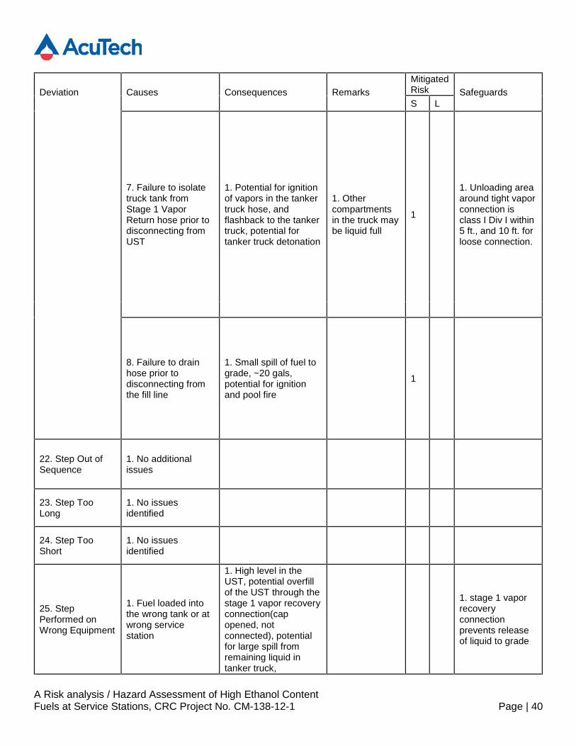
7. Failure to isolatetruck tank fromStage 1 VaporReturn hose prior todisconnecting fromUST
1. Potential for ignitionof vapors in the tankertruck hose, andflashback to the tankertruck, potential fortanker truck detonation
1. Othercompartmentsin the truck maybe liquid full
1
1. Unloading areaaround tight vaporconnection isclass I Div I within5 ft., and 10 ft. forloose connection.
8. Failure to drainhose prior todisconnecting fromthe fill line
1. Small spill of fuel tograde, ~20 gals,potential for ignitionand pool fire
1
22. Step Out ofSequence
1. No additionalissues
23. Step TooLong
1. No issuesidentified
24. Step TooShort
1. No issuesidentified
25. StepPerformed onWrong Equipment
1. Fuel loaded intothe wrong tank or atwrong servicestation
1. High level in theUST, potential overfillof the UST through thestage 1 vapor recoveryconnection(capopened, notconnected), potentialfor large spill fromremaining liquid intanker truck,
1. stage 1 vaporrecoveryconnectionprevents releaseof liquid to grade
A Risk analysis / Hazard Assessment of High Ethanol ContentFuels at Service Stations, CRC Project No. CM-138-12-1 Page | 41
Deviation Causes Consequences RemarksMitigatedRisk SafeguardsS L
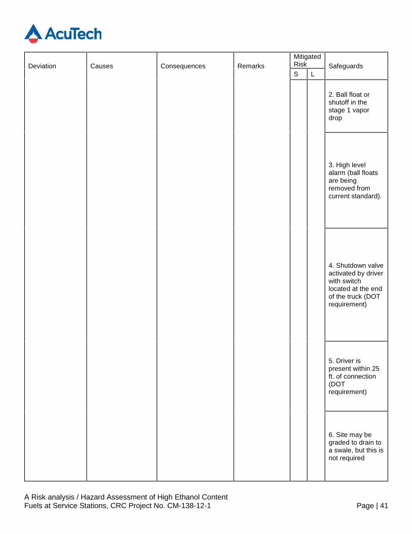
2. Ball float orshutoff in thestage 1 vapordrop
3. High levelalarm (ball floatsare beingremoved fromcurrent standard).
4. Shutdown valveactivated by driverwith switchlocated at the endof the truck (DOTrequirement)
5. Driver ispresent within 25ft. of connection(DOTrequirement)
6. Site may begraded to drain toa swale, but this isnot required

A Risk analysis / Hazard Assessment of High Ethanol ContentFuels at Service Stations, CRC Project No. CM-138-12-1 Page | 42
Deviation Causes Consequences RemarksMitigatedRisk SafeguardsS L
2. Contamination
2. Fill line connectedto vapor returnconnection
1. Splash filling of theUST, no recovery ofvapors from the stage1 connection, potentialto pull vacuum ontruck, see low pressure
1. Liquid andvapor connectionsare notinterchangeable,different sizes
2. Splash filling of theUST, no recovery ofvapors from the stage1 connection, ventingof vapors from USTvent stack, potential forignition and flashbackto UST
1. Liquid andvapor connectionsare notinterchangeable,different sizes
A Risk analysis / Hazard Assessment of High Ethanol ContentFuels at Service Stations, CRC Project No. CM-138-12-1 Page | 43
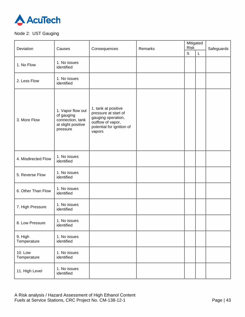
Node 2: UST Gauging
Deviation Causes Consequences RemarksMitigatedRisk SafeguardsS L
1. No Flow 1. No issuesidentified
2. Less Flow 1. No issuesidentified
3. More Flow
1. Vapor flow outof gaugingconnection, tankat slight positivepressure
1. tank at positivepressure at start ofgauging operation,outflow of vapor,potential for ignition ofvapors
4. Misdirected Flow 1. No issuesidentified
5. Reverse Flow 1. No issuesidentified
6. Other Than Flow 1. No issuesidentified
7. High Pressure 1. No issuesidentified
8. Low Pressure 1. No issuesidentified
9. HighTemperature
1. No issuesidentified
10. LowTemperature
1. No issuesidentified
11. High Level 1. No issuesidentified
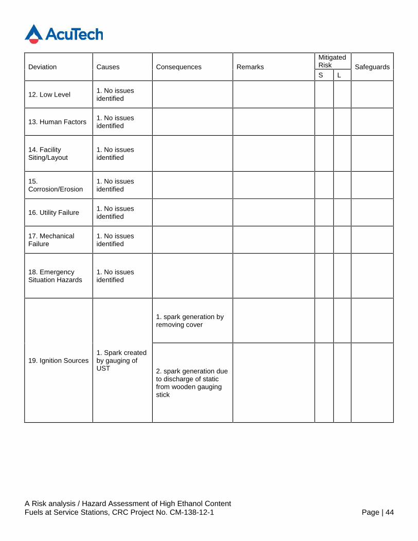
A Risk analysis / Hazard Assessment of High Ethanol ContentFuels at Service Stations, CRC Project No. CM-138-12-1 Page | 44
Deviation Causes Consequences RemarksMitigatedRisk SafeguardsS L
12. Low Level 1. No issuesidentified
13. Human Factors 1. No issuesidentified
14. FacilitySiting/Layout
1. No issuesidentified
15.Corrosion/Erosion
1. No issuesidentified
16. Utility Failure 1. No issuesidentified
17. MechanicalFailure
1. No issuesidentified
18. EmergencySituation Hazards
1. No issuesidentified
19. Ignition Sources1. Spark createdby gauging ofUST
1. spark generation byremoving cover
2. spark generation dueto discharge of staticfrom wooden gaugingstick

A Risk analysis / Hazard Assessment of High Ethanol ContentFuels at Service Stations, CRC Project No. CM-138-12-1 Page | 45
Deviation Causes Consequences RemarksMitigatedRisk SafeguardsS L
2. Electronicgauge createsan ignitionsource due tofailure orinstallation error
1. Gauges may failthough they are ratedfor Class1 div 1 service,gauge may be thesource of ignition fortank headspace
1. gauges in use maybe susceptible toincreased failure ratesin ethanol service due tothe increasedconcentration ofchlorides in ethanolfuels
20. Step Skipped 1. No issuesidentified
21. Step Out ofSequence
1. No issuesidentified
22. Step Too Long 1. No issuesidentified
23. Step Too Short 1. No issuesidentified
24. Step Performedon WrongEquipment
1. No issuesidentified
A Risk analysis / Hazard Assessment of High Ethanol ContentFuels at Service Stations, CRC Project No. CM-138-12-1 Page | 46
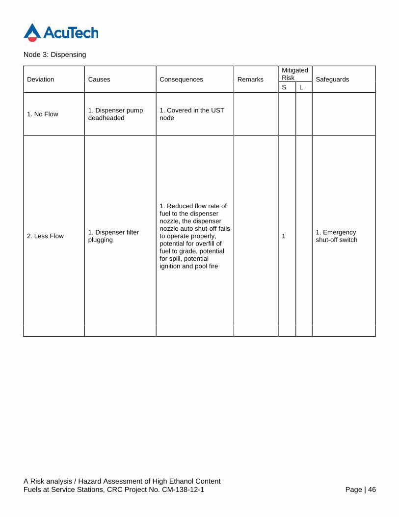
Node 3: Dispensing
Deviation Causes Consequences RemarksMitigatedRisk SafeguardsS L
1. No Flow 1. Dispenser pumpdeadheaded
1. Covered in the USTnode
2. Less Flow 1. Dispenser filterplugging
1. Reduced flow rate offuel to the dispensernozzle, the dispensernozzle auto shut-off failsto operate properly,potential for overfill offuel to grade, potentialfor spill, potentialignition and pool fire
1 1. Emergencyshut-off switch

A Risk analysis / Hazard Assessment of High Ethanol ContentFuels at Service Stations, CRC Project No. CM-138-12-1 Page | 47
Deviation Causes Consequences RemarksMitigatedRisk SafeguardsS L
2. Low tank level inthe UST
1. Reduced flow rate offuel to the dispensernozzle, the dispensernozzle auto shut-off failsto operate properly,potential for overfill offuel to grade, potentialfor spill, potentialignition and pool fire
1 1. Emergencyshut-off switch
A Risk analysis / Hazard Assessment of High Ethanol ContentFuels at Service Stations, CRC Project No. CM-138-12-1 Page | 48
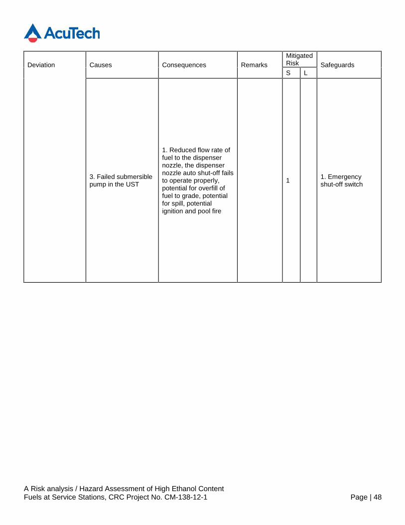
Deviation Causes Consequences RemarksMitigatedRisk SafeguardsS L
3. Failed submersiblepump in the UST
1. Reduced flow rate offuel to the dispensernozzle, the dispensernozzle auto shut-off failsto operate properly,potential for overfill offuel to grade, potentialfor spill, potentialignition and pool fire
1 1. Emergencyshut-off switch
A Risk analysis / Hazard Assessment of High Ethanol ContentFuels at Service Stations, CRC Project No. CM-138-12-1 Page | 49
Deviation Causes Consequences RemarksMitigatedRisk SafeguardsS L
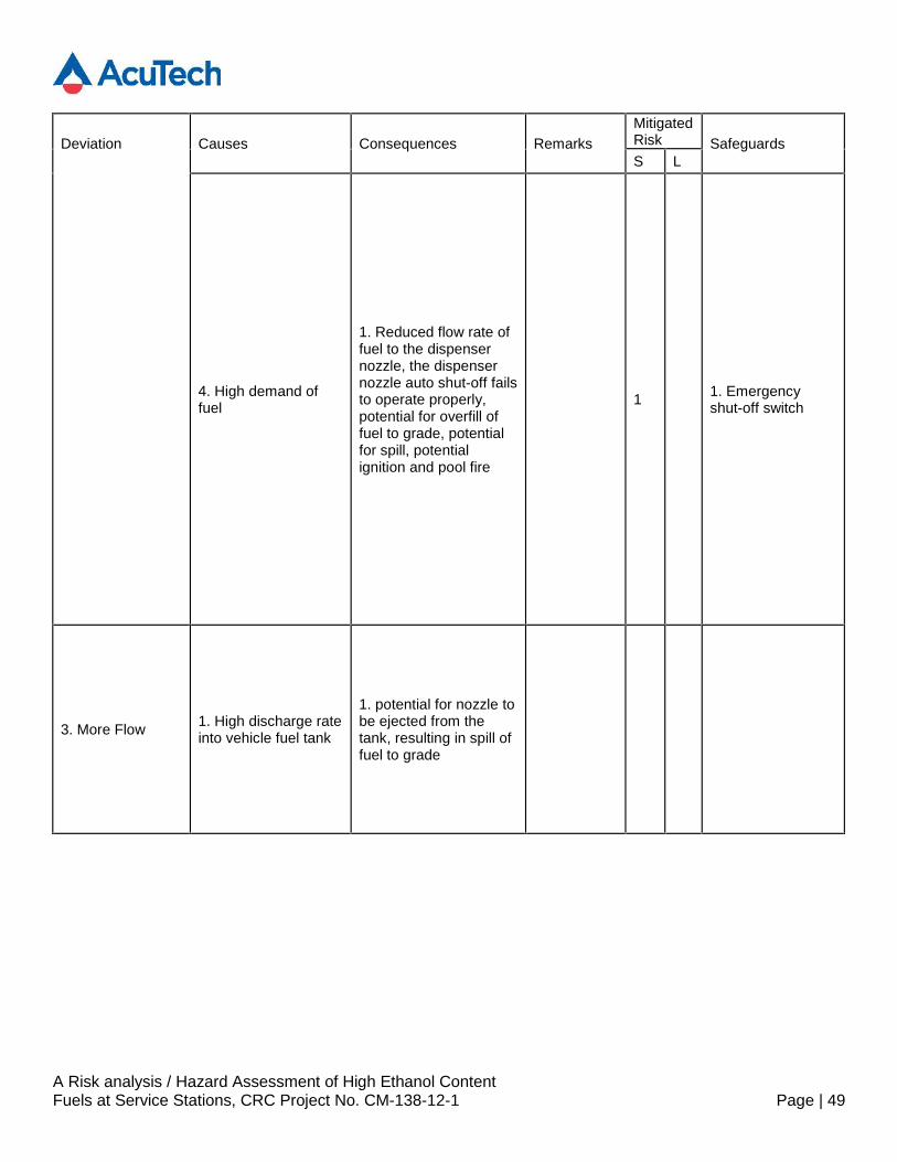
4. High demand offuel
1. Reduced flow rate offuel to the dispensernozzle, the dispensernozzle auto shut-off failsto operate properly,potential for overfill offuel to grade, potentialfor spill, potentialignition and pool fire
1 1. Emergencyshut-off switch
3. More Flow 1. High discharge rateinto vehicle fuel tank
1. potential for nozzle tobe ejected from thetank, resulting in spill offuel to grade
A Risk analysis / Hazard Assessment of High Ethanol ContentFuels at Service Stations, CRC Project No. CM-138-12-1 Page | 50
Deviation Causes Consequences RemarksMitigatedRisk SafeguardsS L
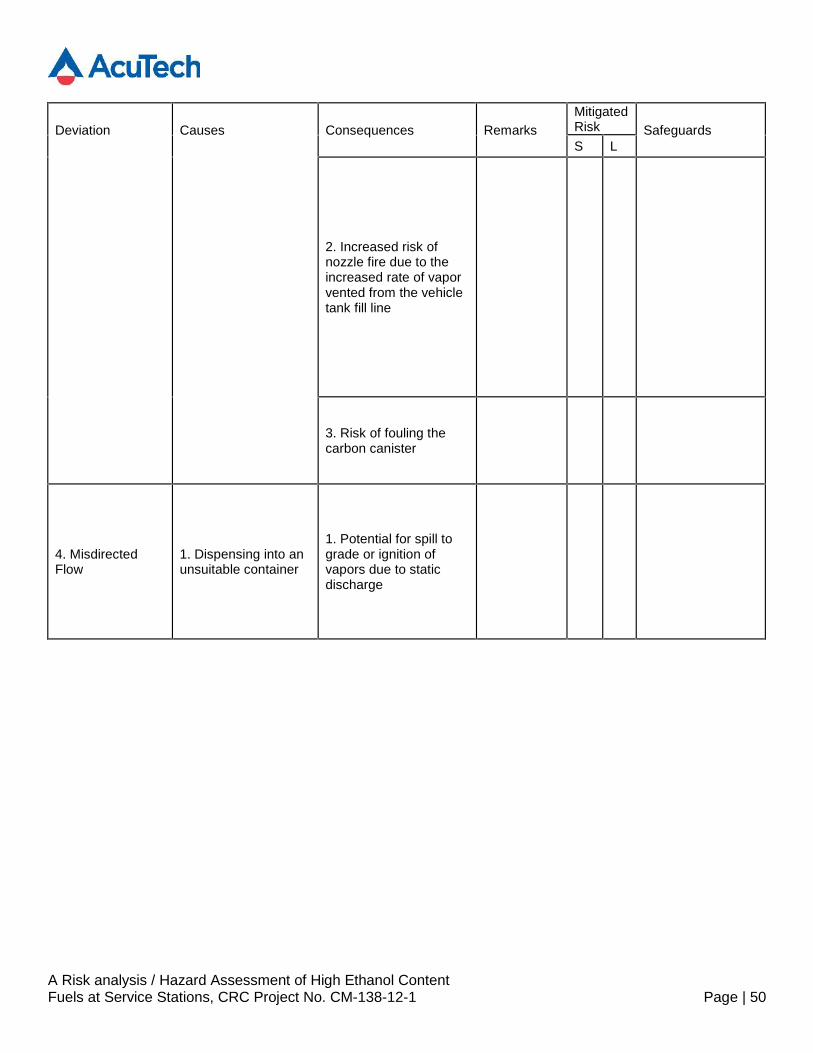
2. Increased risk ofnozzle fire due to theincreased rate of vaporvented from the vehicletank fill line
3. Risk of fouling thecarbon canister
4. MisdirectedFlow
1. Dispensing into anunsuitable container
1. Potential for spill tograde or ignition ofvapors due to staticdischarge

A Risk analysis / Hazard Assessment of High Ethanol ContentFuels at Service Stations, CRC Project No. CM-138-12-1 Page | 51
Deviation Causes Consequences RemarksMitigatedRisk SafeguardsS L
2. Mis-fueling, highethanol fuel into aconventional fuelvehicle
1. potential forflashback in a vehiclethat was not designedto handle ethanol fuels,if flame arrestors areadded to vehicles, thereis an increased risk offlashback in vehicleswithout flame arrestors
5. Reverse Flow1. Drain down of fuelto the UST duringmaintenance
1. Fuel is drained backto the UST duringmaintenance ofdispensing equipment,potential for flamepathway from thedispenser to the UST

A Risk analysis / Hazard Assessment of High Ethanol ContentFuels at Service Stations, CRC Project No. CM-138-12-1 Page | 52
Deviation Causes Consequences RemarksMitigatedRisk SafeguardsS L
6. Other ThanFlow
1. Internal failure ofstage 2 vaporrecovery dispensinghose
1. Leak of fuel from theliquid fill line into thevapor recovery line, lossof vapor flow rate instage 2 vapor recoverysystem, or liquid to thevacuum pump in thestage2 vapor recoverysystem
2. Stage 2 vaporrecovery pullingsuction other thanfrom fuel tank
1. Connection not madewith fuel tank, createsthe potential for aflammable mixture in afuel that is not normallyin the flammable range
A Risk analysis / Hazard Assessment of High Ethanol ContentFuels at Service Stations, CRC Project No. CM-138-12-1 Page | 53
Deviation Causes Consequences RemarksMitigatedRisk SafeguardsS L
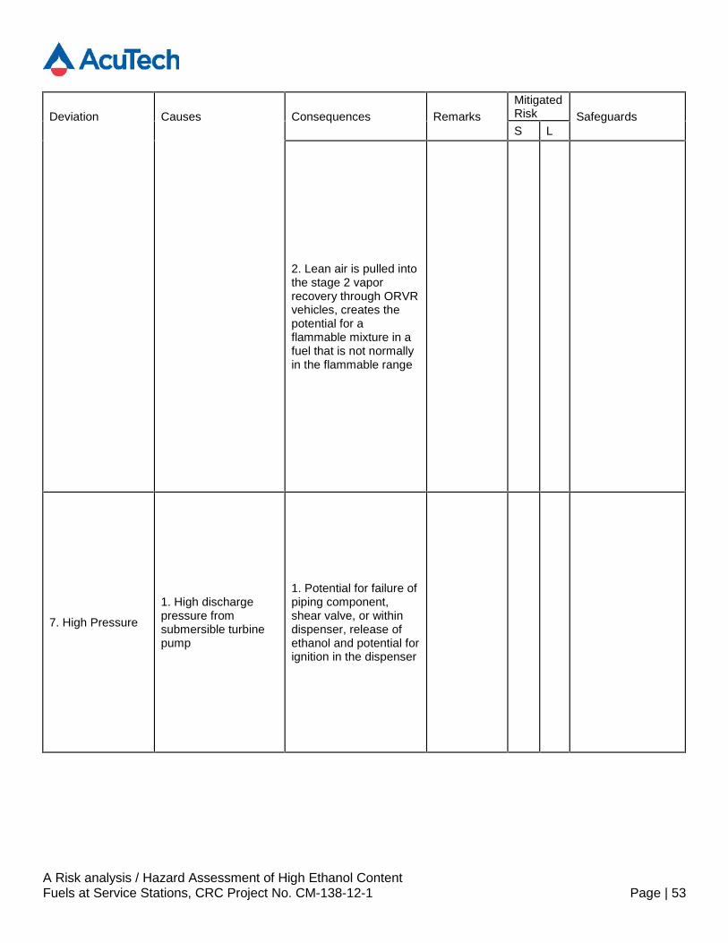
2. Lean air is pulled intothe stage 2 vaporrecovery through ORVRvehicles, creates thepotential for aflammable mixture in afuel that is not normallyin the flammable range
7. High Pressure
1. High dischargepressure fromsubmersible turbinepump
1. Potential for failure ofpiping component,shear valve, or withindispenser, release ofethanol and potential forignition in the dispenser

A Risk analysis / Hazard Assessment of High Ethanol ContentFuels at Service Stations, CRC Project No. CM-138-12-1 Page | 54
Deviation Causes Consequences RemarksMitigatedRisk SafeguardsS L
2. Potential for hosefailure or failure ofbreakaway under highpressure, potential forrelease of fuel to grade
8. Low Pressure1. Increased filterplugging, lowpressure at dispenser
1. High pressure dropacross the filter,potential for failure offilter, release ofparticulate matter intothe dispenser, potentialfor failure of controlvalve in the dispenser,dispenser fails to shut-off flow at pre-determined set point,continued flow of fuel tovehicle, potential foroverfill of vehicle fueltank at reduced flowrate(control valve indispenser leaking by)
1. Nozzle auto-shutoff engageswhen the fuel tankis filled
A Risk analysis / Hazard Assessment of High Ethanol ContentFuels at Service Stations, CRC Project No. CM-138-12-1 Page | 55
Deviation Causes Consequences RemarksMitigatedRisk SafeguardsS L
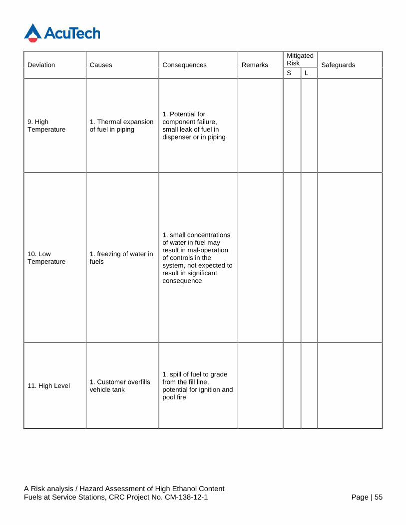
9. HighTemperature
1. Thermal expansionof fuel in piping
1. Potential forcomponent failure,small leak of fuel indispenser or in piping
10. LowTemperature
1. freezing of water infuels
1. small concentrationsof water in fuel mayresult in mal-operationof controls in thesystem, not expected toresult in significantconsequence
11. High Level 1. Customer overfillsvehicle tank
1. spill of fuel to gradefrom the fill line,potential for ignition andpool fire
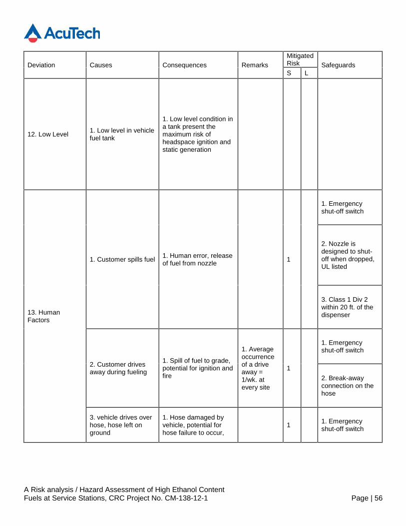
A Risk analysis / Hazard Assessment of High Ethanol ContentFuels at Service Stations, CRC Project No. CM-138-12-1 Page | 56
Deviation Causes Consequences RemarksMitigatedRisk SafeguardsS L
12. Low Level 1. Low level in vehiclefuel tank
1. Low level condition ina tank present themaximum risk ofheadspace ignition andstatic generation
13. HumanFactors
1. Customer spills fuel 1. Human error, releaseof fuel from nozzle 1
1. Emergencyshut-off switch
2. Nozzle isdesigned to shut-off when dropped,UL listed
3. Class 1 Div 2within 20 ft. of thedispenser
2. Customer drivesaway during fueling
1. Spill of fuel to grade,potential for ignition andfire
1. Averageoccurrenceof a driveaway =1/wk. atevery site
1
1. Emergencyshut-off switch
2. Break-awayconnection on thehose
3. vehicle drives overhose, hose left onground
1. Hose damaged byvehicle, potential forhose failure to occur,
1 1. Emergencyshut-off switch
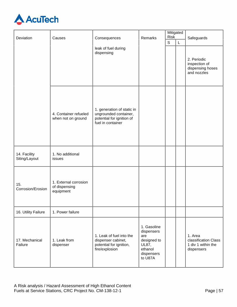
A Risk analysis / Hazard Assessment of High Ethanol ContentFuels at Service Stations, CRC Project No. CM-138-12-1 Page | 57
Deviation Causes Consequences RemarksMitigatedRisk SafeguardsS L
leak of fuel duringdispensing
2. Periodicinspection ofdispensing hosesand nozzles
4. Container refueledwhen not on ground
1. generation of static inungrounded container,potential for ignition offuel in container
14. FacilitySiting/Layout
1. No additionalissues
15.Corrosion/Erosion
1. External corrosionof dispensingequipment
16. Utility Failure 1. Power failure
17. MechanicalFailure
1. Leak fromdispenser
1. Leak of fuel into thedispenser cabinet,potential for ignition,fire/explosion
1. Gasolinedispensersaredesigned toUL87,ethanoldispensersto U87A
1. Areaclassification Class1 div 1 within thedispensers
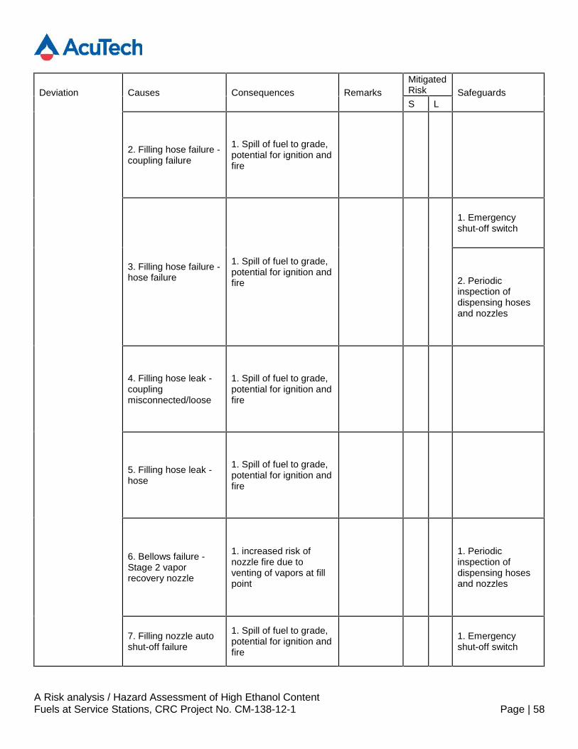
A Risk analysis / Hazard Assessment of High Ethanol ContentFuels at Service Stations, CRC Project No. CM-138-12-1 Page | 58
Deviation Causes Consequences RemarksMitigatedRisk SafeguardsS L
2. Filling hose failure -coupling failure
1. Spill of fuel to grade,potential for ignition andfire
3. Filling hose failure -hose failure
1. Spill of fuel to grade,potential for ignition andfire
1. Emergencyshut-off switch
2. Periodicinspection ofdispensing hosesand nozzles
4. Filling hose leak -couplingmisconnected/loose
1. Spill of fuel to grade,potential for ignition andfire
5. Filling hose leak -hose
1. Spill of fuel to grade,potential for ignition andfire
6. Bellows failure -Stage 2 vaporrecovery nozzle
1. increased risk ofnozzle fire due toventing of vapors at fillpoint
1. Periodicinspection ofdispensing hosesand nozzles
7. Filling nozzle autoshut-off failure
1. Spill of fuel to grade,potential for ignition andfire
1. Emergencyshut-off switch
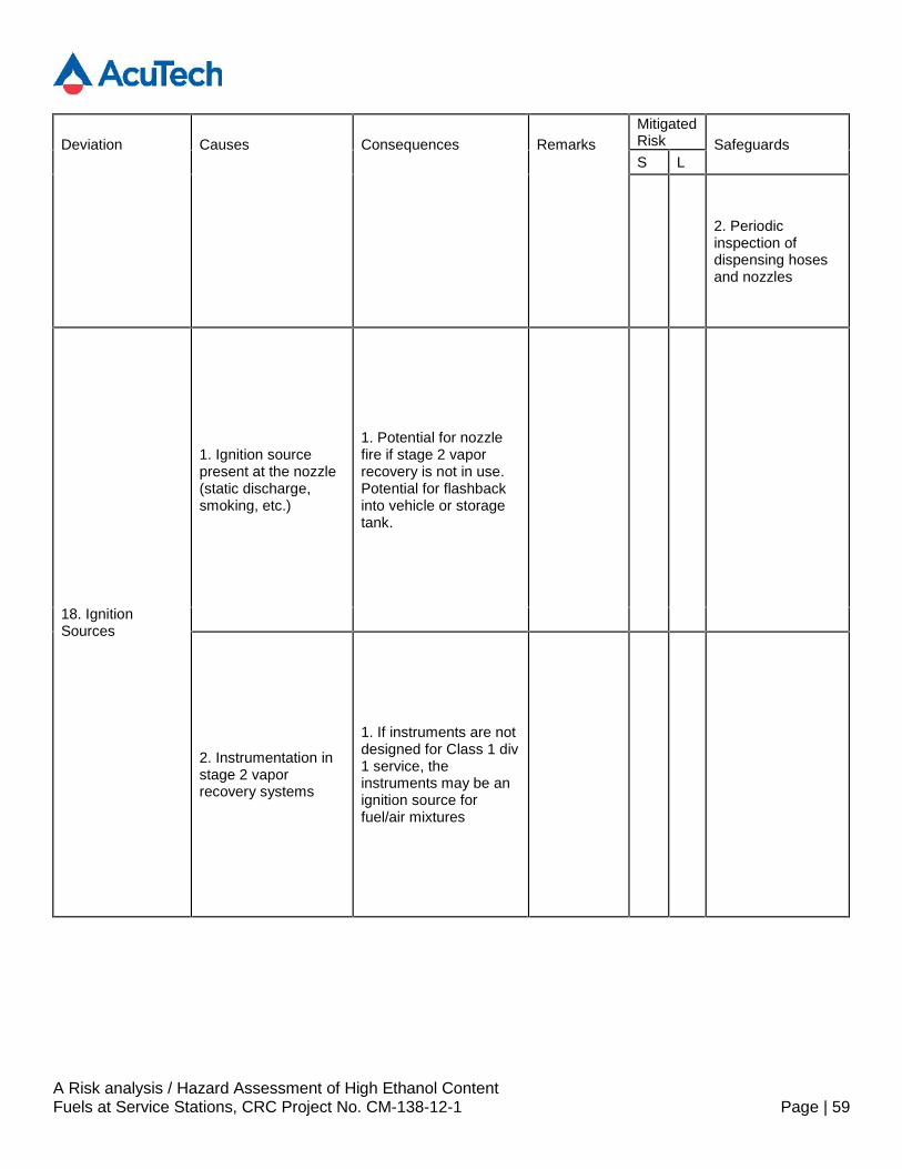
A Risk analysis / Hazard Assessment of High Ethanol ContentFuels at Service Stations, CRC Project No. CM-138-12-1 Page | 59
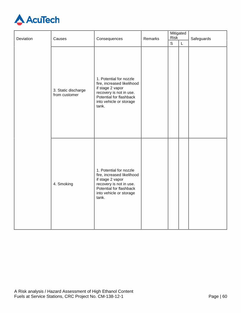
Deviation Causes Consequences RemarksMitigatedRisk SafeguardsS L
2. Periodicinspection ofdispensing hosesand nozzles
18. IgnitionSources
1. Ignition sourcepresent at the nozzle(static discharge,smoking, etc.)
1. Potential for nozzlefire if stage 2 vaporrecovery is not in use.Potential for flashbackinto vehicle or storagetank.
2. Instrumentation instage 2 vaporrecovery systems
1. If instruments are notdesigned for Class 1 div1 service, theinstruments may be anignition source forfuel/air mixtures
A Risk analysis / Hazard Assessment of High Ethanol ContentFuels at Service Stations, CRC Project No. CM-138-12-1 Page | 60
Deviation Causes Consequences RemarksMitigatedRisk SafeguardsS L
3. Static dischargefrom customer
1. Potential for nozzlefire, increased likelihoodif stage 2 vaporrecovery is not in use.Potential for flashbackinto vehicle or storagetank.
4. Smoking
1. Potential for nozzlefire, increased likelihoodif stage 2 vaporrecovery is not in use.Potential for flashbackinto vehicle or storagetank.
A Risk analysis / Hazard Assessment of High Ethanol ContentFuels at Service Stations, CRC Project No. CM-138-12-1 Page | 61
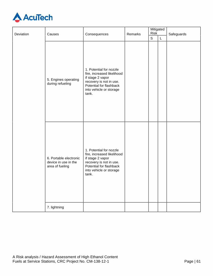
Deviation Causes Consequences RemarksMitigatedRisk SafeguardsS L
5. Engines operatingduring refueling
1. Potential for nozzlefire, increased likelihoodif stage 2 vaporrecovery is not in use.Potential for flashbackinto vehicle or storagetank.
6. Portable electronicdevice in use in thearea of fueling
1. Potential for nozzlefire, increased likelihoodif stage 2 vaporrecovery is not in use.Potential for flashbackinto vehicle or storagetank.
7. lightning
A Risk analysis / Hazard Assessment of High Ethanol ContentFuels at Service Stations, CRC Project No. CM-138-12-1 Page | 62
Deviation Causes Consequences RemarksMitigatedRisk SafeguardsS L
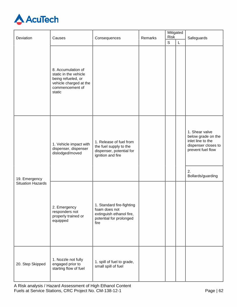
8. Accumulation ofstatic in the vehiclebeing refueled, orvehicle charged at thecommencement ofstatic
19. EmergencySituation Hazards
1. Vehicle impact withdispenser, dispenserdislodged/moved
1. Release of fuel fromthe fuel supply to thedispenser, potential forignition and fire
1. Shear valvebelow grade on theinlet line to thedispenser closes toprevent fuel flow
2.Bollards/guarding
2. Emergencyresponders notproperly trained orequipped
1. Standard fire-fightingfoam does notextinguish ethanol fire,potential for prolongedfire
20. Step Skipped1. Nozzle not fullyengaged prior tostarting flow of fuel
1. spill of fuel to grade,small spill of fuel
A Risk analysis / Hazard Assessment of High Ethanol ContentFuels at Service Stations, CRC Project No. CM-138-12-1 Page | 63
Deviation Causes Consequences RemarksMitigatedRisk SafeguardsS L
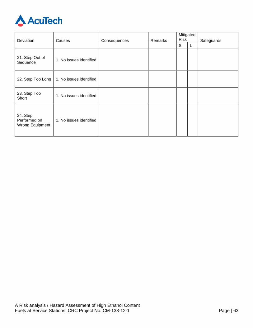
21. Step Out ofSequence 1. No issues identified
22. Step Too Long 1. No issues identified
23. Step TooShort 1. No issues identified
24. StepPerformed onWrong Equipment
1. No issues identified
A Risk analysis / Hazard Assessment of High Ethanol ContentFuels at Service Stations, CRC Project No. CM-138-12-1 Page | 64
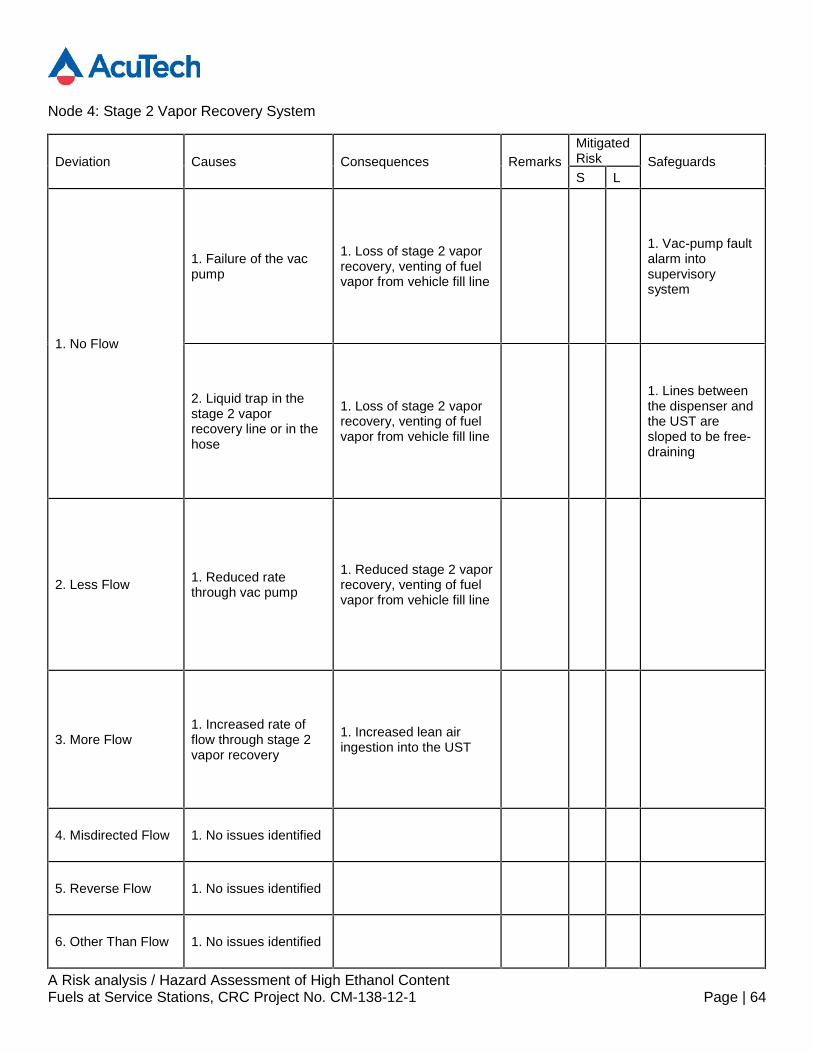
Node 4: Stage 2 Vapor Recovery System
Deviation Causes Consequences RemarksMitigatedRisk SafeguardsS L
1. No Flow
1. Failure of the vacpump
1. Loss of stage 2 vaporrecovery, venting of fuelvapor from vehicle fill line
1. Vac-pump faultalarm intosupervisorysystem
2. Liquid trap in thestage 2 vaporrecovery line or in thehose
1. Loss of stage 2 vaporrecovery, venting of fuelvapor from vehicle fill line
1. Lines betweenthe dispenser andthe UST aresloped to be free-draining
2. Less Flow 1. Reduced ratethrough vac pump
1. Reduced stage 2 vaporrecovery, venting of fuelvapor from vehicle fill line
3. More Flow1. Increased rate offlow through stage 2vapor recovery
1. Increased lean airingestion into the UST
4. Misdirected Flow 1. No issues identified
5. Reverse Flow 1. No issues identified
6. Other Than Flow 1. No issues identified
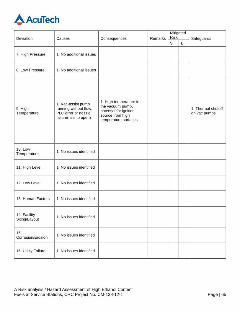
A Risk analysis / Hazard Assessment of High Ethanol ContentFuels at Service Stations, CRC Project No. CM-138-12-1 Page | 65
Deviation Causes Consequences RemarksMitigatedRisk SafeguardsS L
7. High Pressure 1. No additional issues
8. Low Pressure 1. No additional issues
9. HighTemperature
1. Vac-assist pumprunning without flow,PLC error or nozzlefailure(fails to open)
1. High temperature inthe vacuum pump,potential for ignitionsource from hightemperature surfaces
1. Thermal shutoffon vac pumps
10. LowTemperature 1. No issues identified
11. High Level 1. No issues identified
12. Low Level 1. No issues identified
13. Human Factors 1. No issues identified
14. FacilitySiting/Layout 1. No issues identified
15.Corrosion/Erosion 1. No issues identified
16. Utility Failure 1. No issues identified
A Risk analysis / Hazard Assessment of High Ethanol ContentFuels at Service Stations, CRC Project No. CM-138-12-1 Page | 66
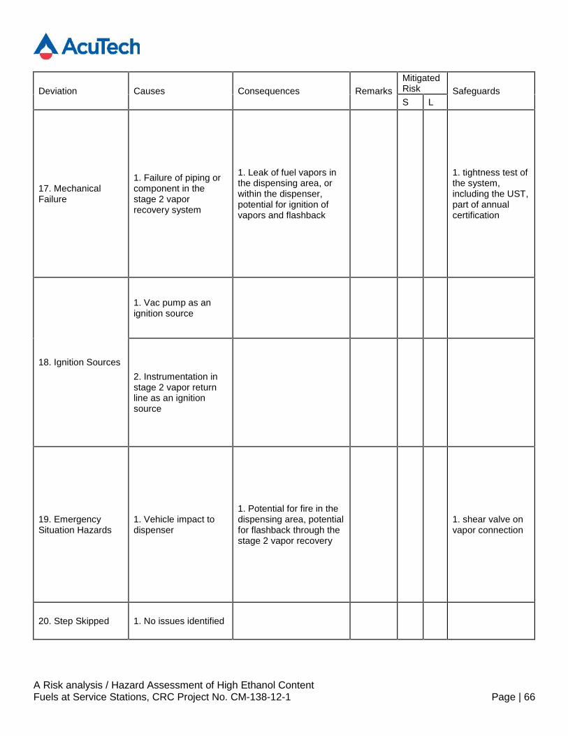
Deviation Causes Consequences RemarksMitigatedRisk SafeguardsS L
17. MechanicalFailure
1. Failure of piping orcomponent in thestage 2 vaporrecovery system
1. Leak of fuel vapors inthe dispensing area, orwithin the dispenser,potential for ignition ofvapors and flashback
1. tightness test ofthe system,including the UST,part of annualcertification
18. Ignition Sources
1. Vac pump as anignition source
2. Instrumentation instage 2 vapor returnline as an ignitionsource
19. EmergencySituation Hazards
1. Vehicle impact todispenser
1. Potential for fire in thedispensing area, potentialfor flashback through thestage 2 vapor recovery
1. shear valve onvapor connection
20. Step Skipped 1. No issues identified
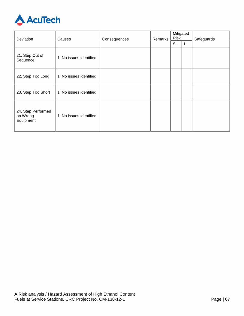
A Risk analysis / Hazard Assessment of High Ethanol ContentFuels at Service Stations, CRC Project No. CM-138-12-1 Page | 67
Deviation Causes Consequences RemarksMitigatedRisk SafeguardsS L
21. Step Out ofSequence 1. No issues identified
22. Step Too Long 1. No issues identified
23. Step Too Short 1. No issues identified
24. Step Performedon WrongEquipment
1. No issues identified