Embed Size (px)
Citation preview
,i= -- -- . .
PROJECT RAND
STRUCTURAL WEIGHT ANALYSIS
WING WEIGHT FQUATIONS
W R. Micks
Accesion For
NTIS CRAMIDTIC TAB
December, 1950 Urlan'nouFr~c J
j Usti i cctiofll
R-198 By..... ......................
Dist, ibu'tion IAvailability
Codes
CPNOD t 1Avail andlorDist Special
COPY NO. I]I
1500 eOUNIH ST. * SANTA MONICA * CALIFOUNIA
Copyright 1950, 1he RAND Corporation

BestAvailable
Copy
CONTENTS
SU MM A RY ................................................. v
SYM BO L S ................................................. vii
I. INTRODUCTION ..................................... 1
II. CHANGES IN THE ORIGINAL WING WEIGHT EQUATIONS 3
III. SHORTENED FORM OF WING WEIGHT EQUATION ....... 7
IV. INERTIA LOAD BELIEF ............................. 9V. METHODS FOR ESTIMATING INERTIA-LOAD INTEGRATION
FACTORS ...................................... 13
Concentrated Loads ............................... 13Distributed Loads ................................ 16
Total Combined Values ............................ 18
VI. CONCLUSIONS ...................................... 19
APPENDIXES
A. DERIVATION OF EXPRESSIONS FOR INERTIA-LOADRELIEF FACTORS ............................... 21
Shear Material ................................... 21
Bending Material ................................. 24B. DERIVATION OF THE INTEGRATED SHEAR REDUCTION
FACTO R ....................................... 29
C. DERIVATION OF REVISED RIB WEIGHT EXPRESSIONS .... 33
Rib Shear Material ............................... 33
Rib Flange Material .............................. 34
D. DERIVATION OF EXPRESSIONS FOR COMBININGINTEGRATION FACTORS ........................ 35
Shear Integration Factors ........................ 35
Bending Integration Factors ...................... 36
REFERENCES ............................................. 39
iii
FIGURES
1. Concentrated loading condition...... ................. 13
2. Shear diagram for concentrated loads .................. 13
3. Integration factors for bending material-concen-trated loads ......................................... 15
4. Shear integration factor for weight distributed aswing volume .......................................... 16
5. Integration factors for bending material for inertialoads distributed as wing volume .................... 17
6. Shear diagram for two superimposed loading conditions ... 35
7. Diagram of axial flange loads for two sources ofbending moments ..................................... 36
iv
SUMMARY
This report presents some refinements to the wing weightestimation methods outlined in RAND Report R-10O.(") SinceReport R-100 was published, the weight equations have beenapplied to a number of modern airplanes to determine certainempirical constants and to observe the relative size of thevarious terms in the equations. Some of these terms werefound to be relatively small. Therefore, it waspossibleto shorten the final equations with little loss of accuracy.
This recent study also showed that the original assumptionsregarding the distribution of dead weight in the wing neededrevision. A more accurate method of accounting for theeffects of dead-weight loads is outlined in this report.
For references, see p. 39 .
v
SYMBOLS
A area
b wing span (aerodynamic), in.
bs wing span (structural) (=b/cosA), in.
C= intercept value for i/Lo for type of constructionused in flanges of the structural box
Cr intercept value for 7/h for type of construction usedin ribs
Cs intercept value for t/h for type of construction usedin the shear material of the structural box
C = mean aerodynamic chord, in.
C = integrated effective moment coefficient
S= structural mean aerodynamic chord (= /cosA), in.
d = ratio of thickness taper ratio to planform taperratio (=-m/X)
Fa = equivalent axial allowable stress for bending, lb/sq in.
F.r = allowable compressive stress in rib flanges, lb/sq in.
h = maximum wing depth at any span-wise station, in.
JLT = weight of leading and trailing edge structure (in-cluding flaps and ailerons) divided by the total wingarea
J, = inertia-load correction factor (as used in ReportR-lO0)
Jnb = inertia-load correction factor for bending loads
J,, = inertia-load correction factor for shear loads
J, = shear reduction factor (as used in Report R-1O0)
#Js = integrated shear reduction factor
KB = width of wing structural box expressed as a fractionof the chord
KL = rib spacing expressed as a fraction of chord (=L/C)
Kh = maximum wing thickness, expressed as a fraction ofchord
k, = ratio of effective column length to actual length(=L 0/L)
vii
kb = span-distribution factor (as used in Report R-100)
kba = span-distribution factor for airloads (also equalto kisa )
kbd = span-distribution factor for inertia loads (alsoequal to kid )
ke = wing effective depth factor
kib = bending integration factor (as used in Report R-100)
kib. = bending integration factor for airloads
kibd = bending integration factor for inertia loads
ki$ = shear integration factor (as used in Report B-100)
ki. = shear integration factor for airloads
kid = shear integration factor for inertia loads
krf = ratio of rear spar depth to airfoil maximum depth(= hf/h)
ks = ratio of average spar depth to airfoil maximum depth( = have/h)
kX = nonoptimum factor for wing primary structure
k; = nonoptimum factor which includes primary and secondarystructure
M = bending moment, in.-lb
Ma = bending moment due to airloads, in.-lb
Md = bending moment due to inertia loads, in.-lb
n = thickness taper ratio (= hT/hR)
Mar = ratio of allowable rib flange stress to equivalent
axial stress (=Far/Fa)
MS = ratio of effective shear stress to equivalent axial
stress (=Fo/,F)
nf = ultimate load factor
P = load, lb
qV = dynamic pressure, lb/sq ft
S = wing area, sq ft
Tro = minimum average thickness for ribs, in.
Va = shear due to airloads, lb
Vd = shear due to inertia loads, lb
VR = value of shear measured at the root section, lb
Wg = airplane gross weight, lb
W = weight of wing, lb
viii
= weight of wing and wing contents, lb
Snondimensional span-wise distance measured from theroot section
= planform taper ratio (=CT/CiR)
ix
I. INTRODUCTION
RAND Report R-100 outlined procedures for applying optimumdesign methods to structural weight analysis of the wing.Subsequent to the publication of Report R-100, the wingweight equations were applied to a number of modern air-planes to check the values of calculated weight against theactual weight. This preliminary study showed the need forrevision of some of the original simplifying assumptionsregarding the distribution of dead weight within the wing.
The procedure for estimating wing weights may generallybe analyzed in two parts:
1. The estimation of the loads applied to the structure,based on a knowledge of the geometric properties ofthe wing and of certain loading parameters
2. The estimation of the weight of structure necessaryto carry these loads.
The accuracy with which weights can be estimated dependsdireLIy on the accuracy with which the designing loads areestimated. The revision of the integration factors representsa means of improving the results of the weight equations byuse of a more accurate method of determining the wing designloads.
For Report R-1O0, the airloads on the wing structure weredetermined by use of Weissinger's method.(2
) These loads inturn were used to calculate iptegration factors as functionsof planform taper ratio, sweepback, and thickness taperratio. The integration factors represent, in nondimensionalform, the volume of material necessary to carry the airloadshear or bending moment for a given wing configuration. How-ever, to obtain the net shear and bending moments, theinertia loads must be taken into account. This may be donein either of two ways: (1) by subtracting inertia loads fromthe airloads and working with net loads only, or (2) bycalculating integration factors separately for airloads andfor inertia loads and using these factors to calculate thenet result. The second of these two methods is used herebecause of its greater convenience.
For references, see p. 39 .
Another revision made in the original equations is achange in the terms representing rib weight. These changeshave been included in order to make the equations more accu-rate. Derivation of the new termq is given in Appendix C.
When the original equations of Report R-100 were triedout on wings corresponding to the configurations and loadingsof several modern wings, it was found that some of the termscould be neglected with no appreciable error. Therefore itwas possible to write the wing weight equation in a shortened,more convenient form. This shortened form of the equation isgiven in Section III.
2
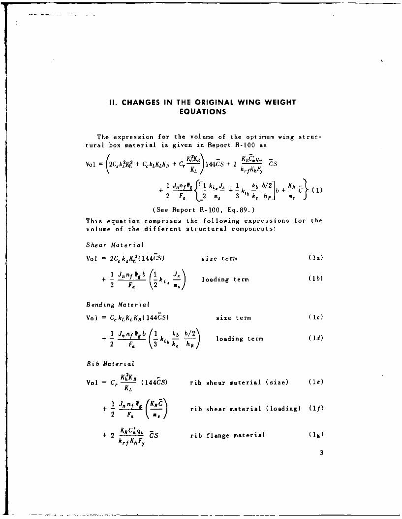
II. CHANGES IN THE ORIGINAL WING WEIGHTEQUATIONS
The expression for the volume of the optimum wing struc-tural box material is given in Report R-100 as
2KhKB\ - KBC.'q, -SVol = CsksKh + CCkLKLKB + Cr 144CS + 2 k CfKhFy
1-Jnwg~k JL" +lk k6 b + KB-+- 1 k --I +-C (1)2 F. LL2 MS 3 ke h,, j S
(See Report R-100, Eq.89.)
This equation comprises the following expressions for thevolume of the different structural components:
Shear Material
Vol = 2CkKht(l44CS) size term (la)1 .J,,nnltsb (l1 Js\
+- 1 loading term (lb)2 Fa (2' MS)
Bending Material
Vol = CCkLKLK8(144CS) size term (lc)+4 jtfnWgb 1 k•, b/2\•=
+ F - N 1 ki kb/ loading term (Id)
Rib Material
Vol = Cr K2K (144CS) rib shear material (size) (le)KL
1 J,, /sK8 C•
+ 1 JffWg I j rib shear material (loading) (1f)2 F. \ ,/
+ 2 KRCsq, rib flange material (lg)kr f Kh Fy
3
One part of Eq.(l) found to need revision is the ex-
pression for the volume of rib material. This change is madeso that the equation describes more accurately the presentpractices in rib construction.
In order to provide a minimum gauge restriction on therib shear material rather than the minimum proportion re-striction provided by Eq.(l), the volume of the size term
for rib shear material is rewritten as
Voi = tr°KBKhS(144) (2)KL
where ro = minimum average thickness of rib shear material.The derivations for the new rib-material terms are presentedin Appendix C.
The expression for the volume of rib flange material,
given by Eq.(lg), is .- termined from a consideration of theamount of flange material necessary to resist chordwisebending moments from the trailing edge structure. Since someof the parameters in Eq.(lg) may be difficult to evaluatein preliminary design stages, the volume of rib flange mate-
rial will be based on a different set of parameters.
The revised expression for rib flange material presented
in Eq.(3) gives the amount of material necessary to carry
the axial loads associated with chordwise bending moments.In this case, the bending moments result from the transferof normal airloads from the point of application in a chord-
wise direction to the shear resisting material in the spars.The expression for the volume of flange material is
Vol = J.WgnfKBC" (3)
4Kh F.,r
where F., = allowable axial stress in the rib flanges. The
derivation of Eq.(3) is given in Appendix C.
When Eqs.(2) and (3) are substituted for the corresponding
rib terms (le) and (1g) in Eq.(1), the volume of wing struc-tural material becomes
Vol = (2C, +CCkLKLKB + 144cS
~ 11 kb (b/2)1 C[ KB 1T+___ ki. L'+l ki b I b+KoCI +_ (4)2F. as 3 ke as
4
where
ar= FarMar
FFa
The term (If), representing the loading term for rib shearmaterial, is not changed.
The optimum weight of the wing structural box is foundby multiplying Eq.(4) by the density w. Using a single over-all nonoptimum factor k, and adding the weight of leadingand trailing edges JTS, the total wing weight is written
W. = Wk" (Csk2K2 + CCkLKLKB + --KB 144h
1 J, nf LFkiJskib kb (b/2)\+ - i + -b
aF. [2 M, 3 ke hR
+ KB /TS (5)(F~~h 1.k\2Khmar msI~
where w = density of the materialkX = actual weight of structural box
optimum weight of structural box
JLTS = weight of leading and trailing edge structureincluding flaps and ailerons.
5
III. SHORTENED FORM OF WING WEIGHT EQUATION
The terms of Eq.(5) were evaluated for several wings ofcontemporary commercial and military airplanes. It was foundthat the terms representing rib flange material and theloading term for the rib shear material, Eqs.(3) and (If),could be omitted with no appreciable effect on the finalnumerical result.
The nonoptimum factor k. is defined as the ratio of theactual structural box weight to the weight of the optimumstructural box. It was originally intended to determinevalues of k, by comparing calculated values of Eq.(5) withactual values of weight for the airplanes studied. However,much of the weight data available at this time was not item-ized in sufficient detail to evaluate JLT with the requiredaccuracy. Therefore, a new nonoptimum factor was defined andused in connection with the statistical study.
To avoid introducing any additional error by using un-certain estimates for values of JLT, the new nonoptimumfactor is defined so as to include the weight of secondarystructure (leading and trailing edge structure).
If the assumption is made that the weight of the secondarystructure is proportional to the weight of the primarystructure, the wing weight is given by
W, = (k, + K1 ) x(optimum weight of structural box). (6)
Let the new nonoptimum factor be defined as
k, = k + Ki. (7)
Then the over-all weight becomes
W. = k,'X(optimum weight of structural box). (8)
In this form, k, could be readily evaluated and was foundto be a function of planform taper ratio, as predicted inReport R-1O0. Due to the classified nature of the weightdata involved, a-ýtual values are not included in this un-classified report.
Omitting the rib weight terms discussed previously, theshortened form of the wing weight equation is now written
W = k w [(2Caks'K + CckLKLKB + K 144ZS
"+ + kib b (9)2 F. (2 m., 3 ke hR
actual wing weightwhere k.' = optimum weight of structural box
8
IV. INERTIA LOAD RELIEF
As shown in Report R-100, part of the wing structuralmaterial is proportional to the size of the wing and partis proportional to the loading. The integration factorsrepresent, in nondimensional form, the volume of materialwhich is proportional to loading. These factors are calcu-lated separately for shear material and bending material.
The value of an integration factor is determined only bythe span-wise distribution of shear load or axial flangeload. It was assumed in Report R-100 that the dead-weightloads had the same distribution as the airloads. Therefore,the distribution of net loads, when plotted nondimensionally,was the same as for airloads and consequently had the samevalue of integration factor. All that was necessary in orderto include the effects of inertia loads was to correct thevalue of loads at the root section. This was done in ReportR-100 by correcting the shear at the root by multiplying bythe factor J., where
J. = W '-WVC (10)Wg
and where Wg = airplane gross weight
W•c = weight of wing and contents.
(See Eq.10a, Report R-100.)
Since it is no longer assumed that the inertia loads aredistributed in the same manner as the airloads, the simplecorrection factor shown above cannot be used. A study ofmodern airplanes has shown that the difference in values ofairload integration factors and net load integration factorsmay be of considerable magnitude in some cases. Therefore,a method was derived for treating the airload and inertia-load integration factors separately and combining them laterto obtain net values. The method is presented below.
The integration factors are obtained from integration ofthe loads expressed in nondimensional form. For shear, thefactor is obtained from an integration of the shear loads.For bending material, it is obtained from an integration ofthe axial flange load expressed nondimensionally. Sincethe portion of the material considered here is operating
9
at constant allowable stresses, the integration factor alsorepresents the amount of material necessary for carryingthe shear or bending.
The airload integration factors have been described previ-ously in Report R-100. The total inertia-load integrationfactors may be composed of several factors which are obtainedseparately for concentrated loads and for distributed loadsand which are then combined. A procedure for the calculationof inertia-load integration factors is outlined in Section V.
After the airload and total inertia-load integrationfactors have been obtained, they are used to calculate valuesof the inertia relieving load factor J,. This factor is de-termined separately for shear and bending material. Asderived in Appendix A, the expressions for J,, are found tobe as follows:
Shear Material,
WVc kisdJin= 1- -g 2AA (11)Wg ki, 0
where kisd = shear integration factor for inertia loads (total)
kia = shear integration factor for airloads;
Bending Material,
Jnb = 1 kibd (12)Wg kba kba
where kbd = span-wise load distribution factor (kisd) forinertia loads
kba = span-wise load distribution factor kis,.) forairloads
kibd = bending integration factor for inertia loads
kib. = bending integration factor for airloads.
The span distribution factor kb is identical with the shearintegration factor ki;. Therefore, values calculated for ki,may be used in Eq.(12).
The two terms Jn, and Jnb are substituted in the wingweight equation in place of the single value of J. previouslyused.
The shear reduction factor J, also required revision inview of the more general assumptions made regarding inertia
10
load distribution. The derivation of Appendix B gives theexpression for the new shear reduction factor as
J=1- kiFb (1-a) (13)3ke L._ s(
tip thicknesswhere ma = thickness taper ratio = root thickness
k, = effective depth factor.
The corrected wing weight equation is obtained by substi-tuting the new values of J., and J, in Eq.(5) of Section II:
tro KBIKhWr =-wk{(2Csk:K2+ CckLKLKB + r KL C t144S
+-. __ __ _ _ --3b 4 e ( b/2V!
+ 1 nfWg inskis. s + 1 JnbBi b
+ KC "2Kar + )] J:TS. (14)
Substituting the new values of Jn and Js in the shortenedform of the wing weight equation, given by Eq.(9), yieldsthe expression
' [(2 2 ZrphKr,
= k ,w[CskK[ + CCkLKLKB + LC 144CSKLC
+ 1 nf___b 1 JiJ 1 kIb (b/2
2 F. (2 Ms 3 ke hR
In the case of a sweptback wing, the values of structuralspan and structural mean aerodynamic chord are used. Thestructural span b, is defined as
bs = (16)cos A
where A = sweepback angle measured at the quarter-chordposition.
The structural mean aerodynamic chord CE is defined as
CS = C cosA. (17)
11
Equation (17) gives exact values only for nontaperedwings. However, except for low-aspect-ratio highly tapereddesigns, these expressions give sufficient accuracy whenused with tapered wings.
In order to write Eq.(15) in a more general form, includingthe effects of sweepback, let
2t Kh2 (1(2=CKh + CkLKLKB + , (18)
/, 1 k.JJ 1 kb. (b./2)\e i.,n + - ki. (19'= \2 3 i6. nb 2 h / (19)
Substituting in Eq.(15), the wing weight becomes
1 o'bswgnf•W= k"' (144P'C 5 S + 6 s .)(20)
12
V. METHODS FOR ESTIMATING INERTIA-LOADINTEGRATION FACTORS
For estimating the integration factors, the inertia loadsare broken down into two general types-distributed and con-centrated. The distributed loads come from the wing structureand from miscellaneous distributed items such as controlsystems. The concentrated loads originate with wing-mountedengines, with landing gear, and sometimes with fuel tanks. Itis usually more convenient to treat the fuel tanks as severalconcentrated loads rather than as a distributed load, sincea restricting assumption is made regarding the manner inwhich the distributed loads vary.
Integration factors are calculated separately for thedifferent loads and are then combined into a single factor.These factors are calculated separately for shear loads andfor bending loads.
CONCENTRATED LOADS
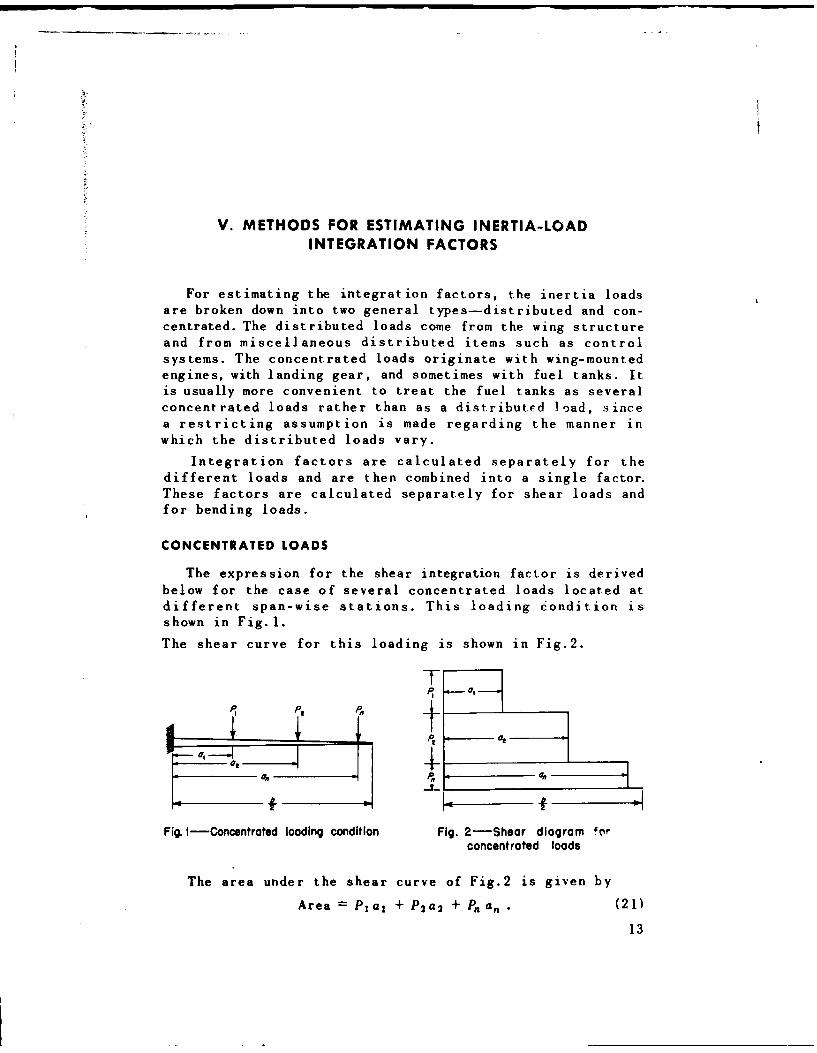
The expression for the shear integration factor is derivedbelow for the case of several concentrated loads located atdifferent span-wise stations. This loading condition isshown in Fig.l.
The shear curve for this loading is shown in Fig.2.
Pt 0
atLl-iI
Fig. I -Concentrated loading condition Fig. 2-Shear diagram 4orconcentrated loads
The area under the shear curve of Fig.2 is given by
Area = Pa, + P 2 a 2 + Pa, , (21)
13

This may be expressed in nondimensional form by dividingby the value of shear at the root and by the semispan (seeAppendix F, Report R-100):
Area' - PaI+P2a2+P.a. (22)(PI+P 2 +Pn) (b/2)
Since the allowable shear stress is a constant for thisportion of the material, Eq.(22) also represents the volumeof shear material expressed in nondimensional form.
The integration factor for shear is defined as the ratio
of the area under the shear curve to that under the shearcurve for the basic case. Since the area equals one-half*for the basic case, the shear integration factor for concen-trated loads is given by
'iad 2 P 1 a 1 +P 2 a 2 +P, a (23)(b/2) PI+P 2 +P2
The integration factor for bending depends on the distri-bution of the axial flange load Pa, where
_M
Pa =- (24)h
and where M = bending moment
h = depth of the wing.
The integration factor kib for bending is defined asfollows:
Let A0 = area under the curve of M/h versus distance alongthe semispan for the given loading condition
Ab = area under the curve of M/h versus distance alongthe semispan for the basic case.
Then
kib = A0 (25)"~Ab
(see Report R-100, page 47.)
For convenience, these areas are expressed in nondi-mensional form. Since the area (nondimensional) under the
curve of M/h for the basic case equals one-third,* thebending integration factor is written
kib = 3A (26)
"*See RAND Report 8-100, pp. 4 6 and 47.
14
where1__ eb/2M•
A= - dx. (27)Mit b f hhft 2
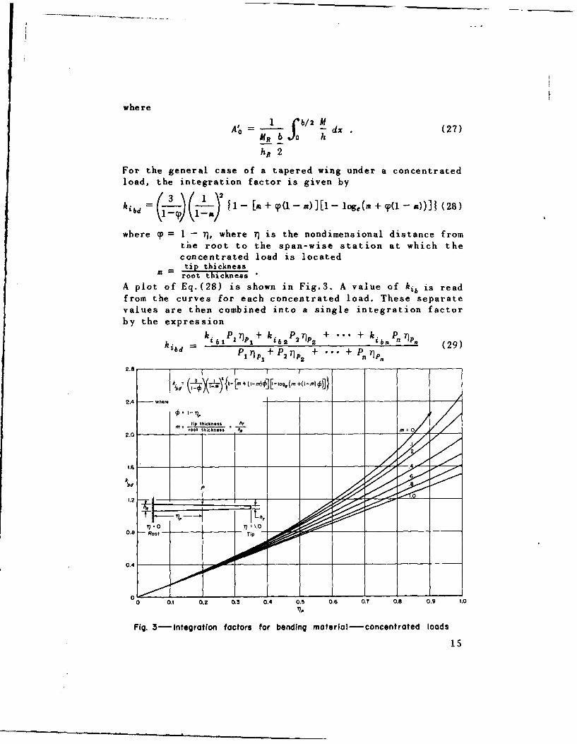
For the general case of a tapered wing under a concentratedload, the integration factor is given by
kibd 3 1- [a + rp(1 -- x)][1-- log,(m + c(1~ -- n))]J (28)
where p = 1 - T), where 7) is the nondimensional distance fromthe root to the span-wise station at which theconcentrated load is locatedtip thickness
a -- root thickness
A plot of Eq.(28) is shown in Fig.3. A value of kib is readfrom the curves for each concentrated load. These separatevalues are then combined into a single integration factorby the expression
k. P )P1)+ kk.P + "" + k.P-ib ~bl i i 2 2)P 2 ibn P. 7nP (29)
-piypj+ p2 ýP2 + ... + "nnp i
2.e _______
k. I - [M+ (1-m")0[1j f- Iag. +(I - M)cP
2.4 where
M tip titickneet hrAm ot thickness M
20
0.8 -- Roof- Tip
0 0.1 0.2 0.3 0.4 0.5 0.6 0.7 0.8 0.9 1.0
71P
Fig. 3-Integration factors for bending material-concentrated loads
15
where ki, = value read from the curves of Fig.3
P = value of concentrated load
71p = nondimensional distance from the location of theload to the wing root section.
Equation (29) is a special case of Eq.(33), which is derivedin Appendix D.
DISTRIBUTED LOADS
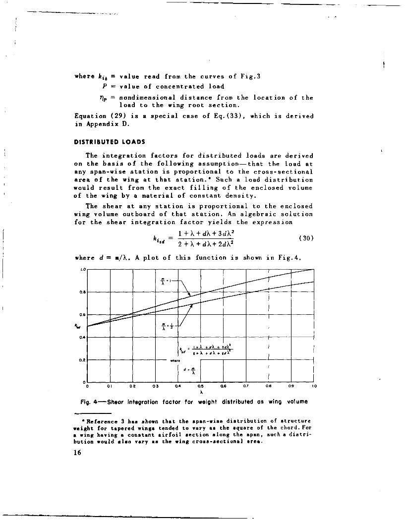
The integration factors for distributed loads are derivedon the basis of the following assumption- that the load atany span-wise station is proportional to the cross-sectionalarea of the wing at that station.* Such a load distributionwould result from the exact filling of the enclosed volumeof the wing by a material of constant density.
The shear at any station is proportional to the enclosedwing volume outboard of that station. An algebraic solutionfor the shear integration factor yields the expression
1 +X+dX+3d 2
kisd= 2 +X+dX+2dX2 (30)
where d = m/X. A plot of this function is shown in Fig.4.
0.8
0.6
0.4
f +k +C) +34,
0.2 who's
0 01 0.2 03 0.4 0.5 0.6 0.7 0.8 0.9 1.0
Fig. 4-Shear integration factor for weight distributed as wing volume
*Reference 3 has shown that the span-wise distribution of structureweight for tapered wings tended to vary as the square of the chord. Fora wing having a constant airfoil section along the span, such a distri-bution would also vary as the wing cross-sectional area.
16
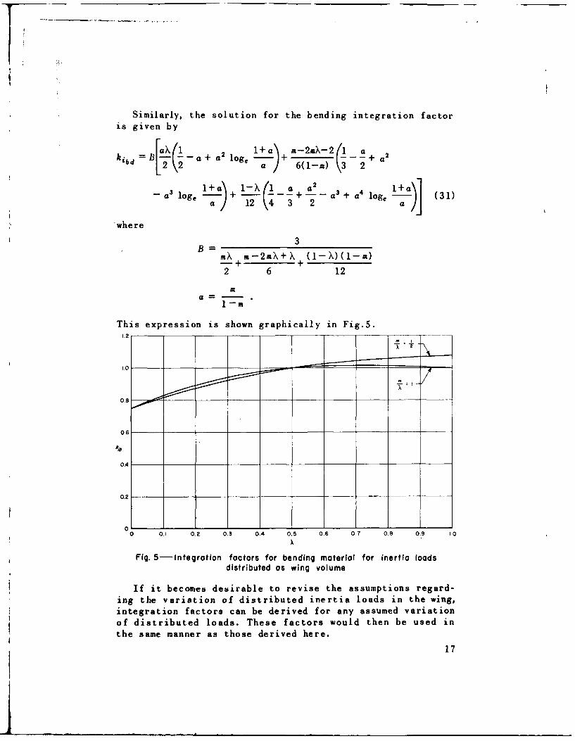
Similarly, the solution for the bending integration factoris given by
-l+a) m-X-2 1--a2kibd =B[2 a +a!a 6(1-rn) \o2
.X --
lo -a+ + 3 4 log -a) (31)a / 2 3 2 aJwhere
3B rnX m-2mX+X (1- X)(1-m)
-t +
2 6 12
Ma =-1-rn
This expression is shown graphically in Fig.5.1.2
1.0
0.8
0-6-
0.4 -
0.2
0 0.1 0.2 0.3 0.4 0.5 0.6 0,7 0.8 0.9 1.0
Fig. 5-Integration factors for bending material for inertia loadsdistributed as wing volume
If it becomes desirable to revise the assumptions regard-ing the variation of distributed inertia loads in the wing,integration factors can be derived for any assumed variationof distributed loads. These factors would then be used inthe same manner as those derived here.
17
TOTAL COMBINED VALUES
After values of the integration factors have been calcu-lated separately for concentrated and distributed loads,these values must be combined to give total values forinertia-load integration factors. This is done for the shearand bending factors by means of the expressions given below.
The total value for the inertia-load shear integrationfactor is given by
k, k 11 VRIi + k1 2 VR2 + ... + ki,. V8 n
V8 1 +V 8 + --. + vRn (32)
wherp ki, = shear integration factor for any given load.
VR = corresponding value of shear at the root.
The total integration factor for bending material isgiven by
k ki.lMRl+kibBMtv2 + "'. + kiblMR, (33)1bd Mi 1 + Mt2 + ... + Min
where ki, = bending material integration factor for any givenload
MR = corresponding value of bending moment at the root.
The derivation of these expressions is given in Appendix D.
18
VI. CONCLUSIONS
In order to improve the accuracy of the equation for
estimating wing weight it was necessary to use a more accu-
rate method of estimating the loads on the wing structure.This required a more precise procedure for estimating the
effects of dead-weight loads, such as the method outlinedin this report. The use of this refined method is more im-
portant for large airplanes having wing fuel and wing-mountedengines than for airplanes which have no sources of large
concentrated loads in the wings.
The shortened form of the weight equation (Eq.20) usingthe over-all nonoptimum factor k.' is the most convenient formto use in the estimation of wing weights on the basis ofcurrently available weight data. The nonoptimum factor k, may
be determined from statistics and expressed as a function ofplanform taper ratio.
Values of airload and inertia-load integration factorswere obtained from actual bending moment curves and were
checked against values calculated by the methods outlined inthis report. The values were in good agreement, the bestcorrelation being obtained for the larger airplanes.
19
APPENDIX A
DERIVATION OF EXPRESSIONS FOR INERTIA-LOADRELIEF FACTORS
In the derivation of integration factors for the shearand bending materials (see Report B-lO0) it was assumed thatthe dead weight of wing and contents had the same distri-bution as the airloads. The use of J, as outlined previouslygives the correct net values of shear and bending moment atthe wing root section but does not account for the actualdistribution of dead weight.
An investigation of the distribution of dead-weight shearand bending moments for actual airplanes has shown that theuse of J, alone yields somewhat optimistic values for theweights of shear and bending material. This is particularlytrue for large airplanes having engines mounted in the wings.
In order to make the wing weight equations more accurateby accounting for the actual distribution of dead weight, thefollowing derivation is presented.
The shear and bending materials discussed here are thoseportions only which vary with loading and which operate atconstant allowable stresses. The portions which are pro-portional to size are not affected.
SHEAR MATERIAL
Equation (84) of Report R-100 gives the expression forthe volume of shear material as
(Vol)s = , ki.A3Rb (34)
where hi, = integration factor derived on the basis of air-loads
ASR = area of shear material required at the rootsection and given by
1S = _1 WgflJs J.. (35)2 Fso
Substituting Eq.(35) in Eq.(84), the volume of shear ma-terial becomes
(Vol), (4Fo (36)
21
The use of J, gives the required area of shear materialcorrected for the relieving shear from dead weight. However,in actual airplane wings, the value of shear relief given by'the term J. is correct only at the root section, since thedead-weight shear is not proportional to the airload shearat all span-wise stations. This difference can be accountedfor by using a combination of two integration factors-onefor airloads and one for the relieving dead-weight loads.
The net cross-sectional area of shear material requiredat any station is given by
A, V. - V (37)
F.10
where Va = shear from airloads
Vd = shear from dead-weight loads.
The volume of shear material is found by integration ofEq. (37):
(Vol). = Ffo Va -f 'Vd . (38)
The subscript R designates values taken at the rootsection, and the value of V. at the root section is givenby
VaR = WgfnfJ, . (39)
The value of Vd at the root section is given by
Vd = W.nf J, (40)
where WVc = weight of wing and contents.
Multiplying and dividing the first and second terms ofEq.(38) by Eqs.(39) and (40), respectively, the volume ofshear material may be written
(Vol), = WgflJsb vao V- - W.,nfJ.ob /d d1 . (41)
2Fo VaR 2F o f Vd
This assumes that the shear from airloads is greater thanthe dead-weight shear at all span-wise stations and was truefor the most critical design condition for all of the air-planes studied.
22
Since the allowable shear stress is constant, the cross-sectional area of shehr material is directly proportional tothe shear load. Therefore,
-. As (42)V aR A• °a
where A.. = area of shear material which would be required
to carry airloads only. Also,
Vd A,,d-d (43)
Vd R AsdR
where Asd = area of shear material which would be requiredto carry dead-weight loads only. Substituting Eqs.(42) and(43) into Eq.(41) and factoring,
(Vol),8 - nf- wgJ dv - W., dv)] (44)21 8 SR f 8dR I
Since the integration factors are evaluated here for bothairloads and inertia loads, it is necessary to use subscriptsa (airload) and d (dead-weight load) with the integration
factors. The value of ki,. of this report corresponds tokis of Report R-100, ki.. corresponds to kib, etc.
The integration factor for airloads is defined as
hisa = 2 1 s d• . (45)AsaR
This expression is the same as that given by Eq.(F-1) in
Report R-100.
The integration factor for dead-weight loads is defined as
kisd = 2 j 1 A dv). (46)AsdR
This factor can be evaluated from a knowledge of the distri-bution of the dead weight of wing and contents.
Substituting Eqs.(45) and (46) into Eq.(44), the volumeof shear material becomes
(Vol)- nfJb (Wgkis - WWckild) (47)(v34F
23
Factoring out the terms associated with airloads,
(Vol). = WgnfJ.sbki. (1 - W.C kisd (48)4F,0 Wg- ki /,
Equation (48) is the same as Eq.(36) with J, replaced by theterm in parenthesis. It can be seen that this term, whichrepresents an integrated dead-weight relief factor, reducesto Jn(=1- Wwc/Iwg) when the integration factors are equal.This would occur if, as previously assumed, the dead weightwere distributed in the same manner as the airloads. The re-vised inertia-load integration factor for shear materialwill be denoted by J,, where
Jn, W~c k isd
Ng kis .
BENDING MATERIAL
The volume of bending material which is proportional toloading is given by Eq.(85) of Report R-100:
(VoI)b = 1 kibAbsb (49)
where kib = integration factor calculated on the basis ofairloads
AbR = cross-sectional area of bending material re-quired at the root section, and where
-Wgff b/2 ) kb (50)2b - hf keF.
Substituting Eq.(50) into Eq.(49), the volume of bendingmaterial is written
-Wgnj (b/2 bkbkibJn (51)
6 hRi / ke a
Here, as in Eq.(36), J, gives the correct value for dead-weight load relief effects only at the root section. Thespan-wise load distribution factor k6 ond the integrationfactor ki, for bending material are based only on airloads.
24
The net cross-sectional area of bending material requiredat any station is given by
2Ab = (Ma - Md) (52)
where Ma = bending moment from airloads
Md = bending moment from dead-weight loads.
The volume of bending material is found by integratingEq. (52):
(Vol)b - 1 M' d f I Mdd 71 (53)Fa k h Fa e,
This assumes that the bending moments from airioads aregreater than those from dead-weight loads at all span-wisestations.
The value of Ma/h at the root section is given by
-at Wgnff /kb 0 (54)h 4 )kb.4
where kb. = span-wise load distribution factor for airloads.
The value of Md/h at the root section is given b-,
hdR = W1 ,nJ ýb/2 kbd (55)
_hR 4 fkh /b)
where kbd = span-wise load distribution factor for dead-weight loads.
Multiplying and dividing the first and second terms ofEq.(53) by Eqs. (54) and (55), respectively, the volume ofbending material is written
Wgflf (/2)~ ____
(Vol)b = Ro_ N1/h2F.•/-• def N R}h
!__ ho Nd/1h dr]. (56)JOf Nd 1/hR5
25
Since the allowable axial stress is constant, the cross-sectional area of bending material required at any station isdirectly proportional to the quantity M/h. Therefore,
Ab_ Ma/h57)A6,, Malt/h(
where Ab, = area of bending material which would be required
to carry airloads alone. Also,
Abd _ Md/h
AbdR Mdl/hR (58)
where Abd = cross-sectional area of bending material whichwould be required to carry only dead-weight loads.
Substituting Eqs.(57) and (58) into Eq.(56) and factoring,the volume of bending material becomes
(VIb=1 (b/2) bnf 1"gb -A-b ('1-W~kb A bd d rl. (59)2 Ab f Abd I
The integration factor for bending material required byairloads is defined as
fol = d3 .a (60)SAb6
This expression is the same as the original equation for thebending-material integration factor given by Eq.(F-6) ofAppendix F, Report R-100.
The integration factor for bending material which wouldbe required to carry only dead-weight loads is defined as
kibd = 3 Abd d•] (61)f A bdRt
Substituting Eqs.(60) and (61) into Eq.(59), the volumeof bending material is written
(Vol)b = Fake (W2 kba0kba - W.kbdk ibd) • (62)
26
Factoring out the quantities associated only with airloads,the volume of bending material becomes
(Vol)b = Wgnflb2\1 bkb~kiba ! -C Lkbd ki (63)6 VhRI Fa ke \ W, kb. kib/)
This expression for volume of bending material is the sameas Eq.(51), except that the dead-weight relief factor Jn isreplaced by the integrated relief factor in parenthesis. Thisrevised inertia-load relief factor for bending material isdenoted by Jab, where
1 - kbd kibdWg kb. kibG
It can be shown algebraically that the integration factorki. for shear material is identical with the span-wise loaddistribution factor kb. For purposes of explanation thetwo factors are left in their original form, but thisidentity should be kept in mind when calculating actualvalues.
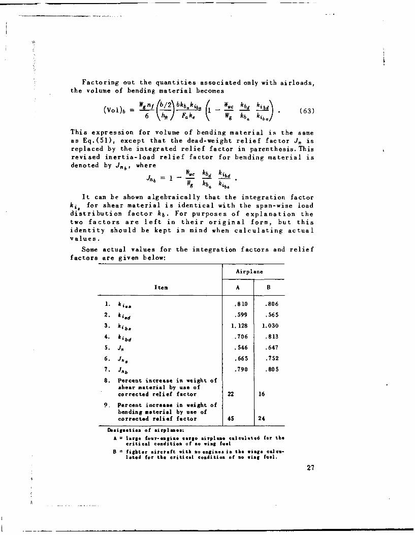
Some actual values for the integration factors and relieffactors are given below:
Airplane
Item A B
1. kiss .810 .806
2. k isd .599 .565"3 hib. 1. 128 1.030
4. kibd .706 .813
5. J, .546 .647
6. J,, .665 .752
7. Jab .790 .805
8. Percent increase in weight ofshear material by use ofcorrected relief factor 22 16
9, Percent increase in weight ofbending material by use ofcorrected relief factor 45 24
Desigmation of airplanes:
A large four-angine cargo airplane calculated for thecritical condition of no wing fuel
B =fighter aircraft with no engines in the wings calcu-lated for the critical condition of no wing fuel.
27
The errors introduced by using J,, rather than the inte-grated relief factor can be seen by comparing Items 6 and 7with Item 5. The percentage error is seen to be larger forthe four-engine cargo airplane.
When more detailed data are acquired on wing loads foractual airplanes, these factors P., and J" b) can be evaluatedfor a number of airplanes, and perhaps average values canbe computed for different classes of airplanes.
28
APPENDIX B
DERIVATION OF THE INTEGRATED SHEARREDUCTION FACTOR
The expression for the shear reduction factor J, givenby Eq.(A-8) of Report B-100 is valid only at the root sectionof the wing. An investigation of actual airplane wings hasshown that the variation in the value of Js along the spanmakes necessary the use of an average or "integrated" value.This integrated shear reduction factor, when substitutedin the general wing weight equation, yields an amount ofshear material which is corrected for the over-all effectof shear relief along the span.
The integrated shear reduction factor, denoted by J,, isdefined as follows:
il = (Vol)s0 (64)
(Vol)0,
where (Vol)s, = volume of shear material necessary to carrythe shear load after it is corrected for re-
lieving shear loads from the flanges
(Vol)so = volume of shear material necessary to carrythe total uncorrected shear load.
This expression may also be written
= 1 (Vol),f (65).(Vol)0
where (Vol).f = volume of material which is subtracted fromSo when relieving shear is considered.
The volume of shear material before correcting for shearrelief is
1 V ki, b (66)(V°I) 80 2 F8 0
where Va = maximum shear load at the root of one wing.
29
The volume of shear material "removed" by considering shearrelieving loads from the beam flanges is
(Vol) 1) = 2 Job/2 dy (67)
where VF = portion of the shear load resisted by axial loadsin the flanges. The shear V1 is given by Eq.(A-2) of ReportR-1O0 as
Vf = P tan 0. (68)
For the general case, the rate of change of depth perunit span is given by
tan 0= hn(l-r) (69)b/2
depth at tipwhere m
depth at root
The flange load P is given by
P = - ' (70)ke h
The depth h at any station y is given by
h = hR [1Y- (1 - M)] . (71)
Substituting Eqs.(71), (70), and (69) into Eq.(68), theportion of the shear load resisted by the flanges is ex-pressed as
V MhR (l-m) (72)
k.( )h [1 - (-m)
Simplifying,
M(1-m) (73)2 6/ke)0 -
30

Substituting Eq.(73) into Eq.(67) and expressing thespan-wise distance y in terms of r], where = y/(b/2),
(Vol)sf = 2(1-m) I M dý. (74)kPke•so f - r + dm (
Multiplying and dividing by the bending moment MR at theroot section,
2(1--m)MR ('1 M/M8 r. 75(Vol)s.,f =1 -2(-T]m di. (75)
Equations (F-5) and (F-6) of Appendix F, Report R-100,show that
SM/MR kib (76)
1- f)+ T]m 3
where kib = integration factor for bending material.
Substituting Eq.(76) into Eq.(75),
(Vol)Sf 2 (1-m)MRkib (77)3 - F, 0keF5
Substituting Eqs. (77) and (66) intoEq.(65), the integratedshear reduction factor becomes
s= 1 -/M-(-)k b01- M) (78)3k-v / kei, b"
As shown in Appendix F of Report R-l00, the followingexpression may be written
lz=kb4(')- = k is(4)b. (79)
Substituting Eq.(79) into Eq.(78) and simplifying, theintegrated shear reduction factor is written
J 1 k ( - • (80)3 ke
The expression for .1' given by Eq.(80) is derived hereto replace Eq.(A-8) of Report R-100. Equation (80) has beenderived on the basis of net shear and bending loads. Whenthe airloads and inertia loads are treated separately, itis necessary to go through the derivation above and toexpress the net moment M as M. - Md, the shear V as Va - Vd,
31
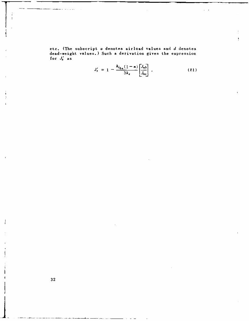
etc. (The subscript a denotes airload values and d denotesdead-weight values.) Such a derivation gives the expressionfor J.' as
= -kib. (1 m) [Jn(3ke Ljn.1
32
APPENDIX C
DERIVATION OF REVISED RIB WEIGHT EXPRESSIONS
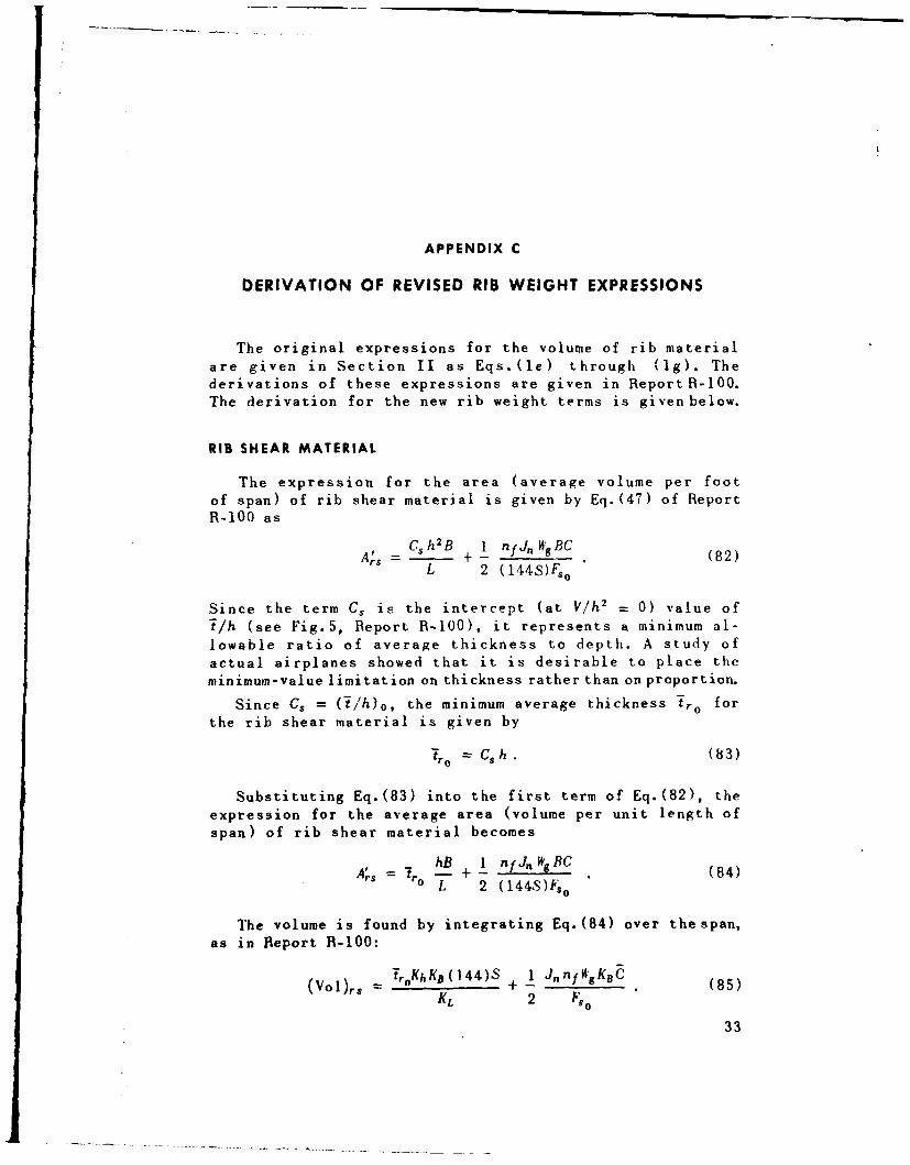
The original expressions for the volume of rib materialare given in Section II as Eqs.(le) through (Ig). Thederivations of these expressions are given in ReportR-100.The derivation for the new rib weight terms is given below.
RIB SHEAR MATERIAL
The expression for the area (average volume per footof span) of rib shear material is given by Eq.(4 7 ) of ReportR-100 as
C +h2 B 1 nfJn WgBC (82)
L 2 (144S)F, 0
Since the term C, is the intercept (at V/h 2 - 0) value of
i/h (see Fig.5, Report R-100), it represents a minimum al-lowable ratio of average thickness to depth. A study ofactual airplanes showed that it is desirable to place theminimum-value limitation on thickness rather than on proportion.
Since Cs = (i/h) 0 , the minimum average thickness Tro forthe rib shear material is given by
tro = Csh (83)
Substituting Eq.(83) into the first term of Eq.(82), theexpression for the average area (volume per unit length ofspan) of rib shear material becomes
A' = hB + 1 n J, WgBC (84)rs ro L 2 (144S)ks°
The volume is found by integrating Eq.(84) over the span,as in Report R-100:
(Vol)rs = T_0KhKB(144)S + 1 JnnfK'gKBC (85)K1, 2 F5o
33
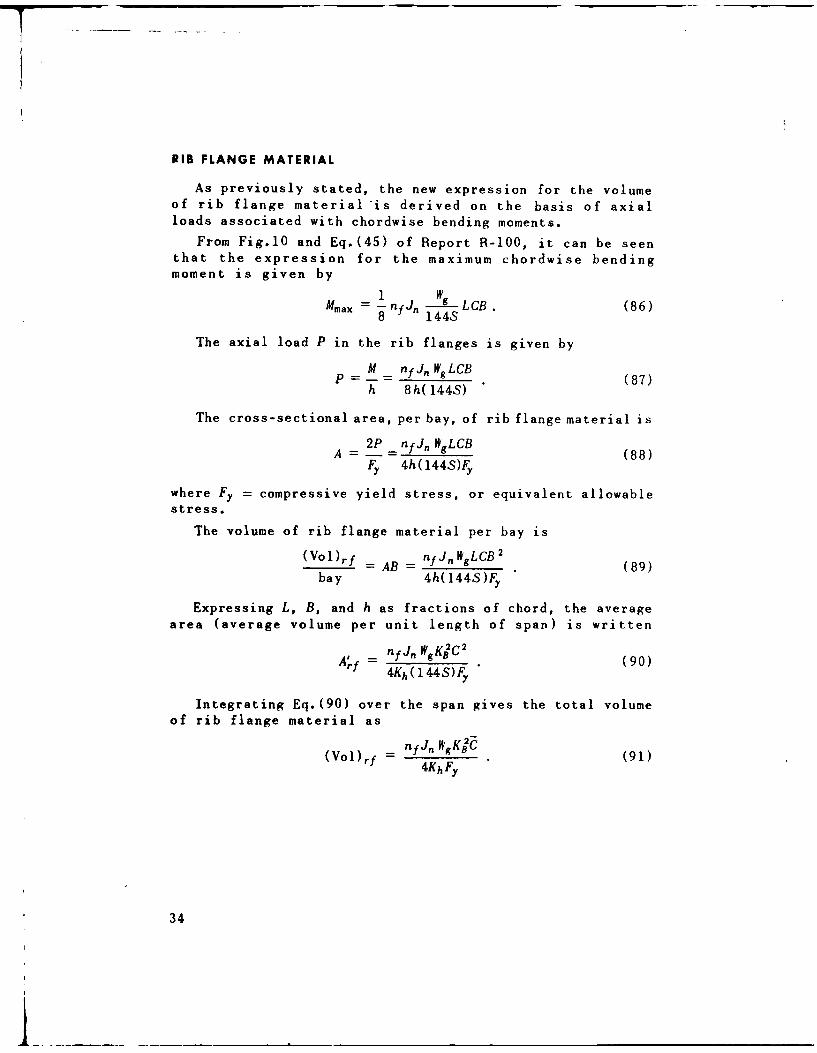
RIB FLANGE MATERIAL
As previously stated, the new expression for the volumeof rib flange material is derived on the basis of axialloads associated with chordwise bending moments.
From Fig.10 and Eq.(45) of Report R-100, it can be seenthat the expression for the maximum chordwise bendingmoment is given by
1 WgMmax -=flfJn gLCB. (86)
8 1448
The axial load P in the rib flanges is given by
M nf Jn W8 LCBP = - (87)
h 8h(144S)
The cross-sectional area, per bay, of rib flange material is
2P nfJnWgLCBA = f- = (88)
Fy 4h(144S)Fy
where Fy = compressive yield stress, or equivalent allowablestress.
The volume of rib flange material per bay is
(Vol)rf = AB = nffJn WgLCB 2 (89)
bay 4h(144S)Fy
Expressing L, B, and h as fractions of chord, the averagearea (average volume per unit length of span) is written
A'rf = n f J" WgKB2C2 (90)4Kh(144S)Fy
Integrating Eq.(90) over the span gives the total volumeof rib flange material as
(Vol,= nfJnWKBC (91)4KhFy
34
APPENDIX D
DERIVATION OF EXPRESSIONS FOR COMBININGINTEGRATION FACTORS
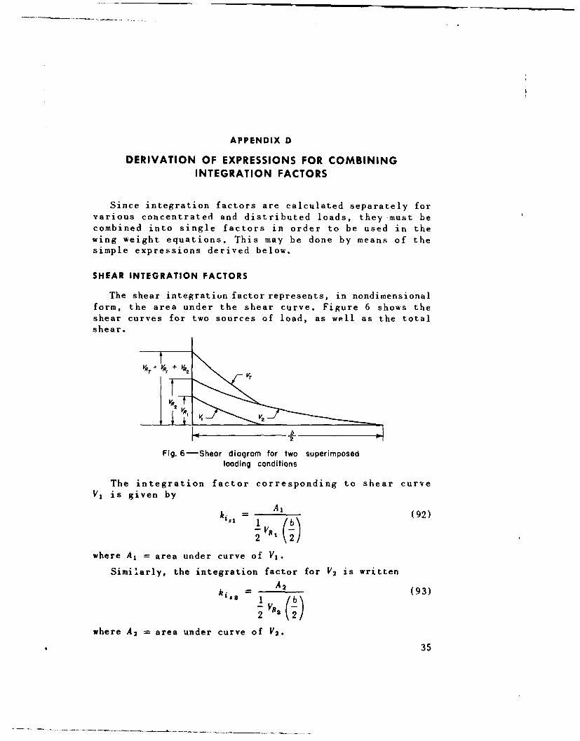
Since integration factors are calculated separately forvarious concentrated and distributed loads, they must becombined into single factors in order to be used in thewing weight equations. This may be done by means of thesimple expressions derived below.
SHEAR INTEGRATION FACTORS
The shear integration factor represents, in nondimensionalform, the area under the shear curve. Figure 6 shows theshear curves for two sources of load, as well as the totalshear.
Fig. 6-Shear diagram for two superimposedloading conditions
The integration factor corresponding to shear curveV1 is given by
ki = A1 (92)1i Ib\
where A, = area under curve of V1 .
Similarly, the integration factor for V2 is written
ki* _ A2 (93)
where A2 = area under curve of V2 .
35
The over-all integration factor ki$T, which is to bewritten in terms of ki., and ki3 2, is given by
~sT ~ A1 +A 2kiiT = 1 A,+bA (94)
S(VR1 + VR )(2
Solving Eqs.(92) and (93) for Al and A2 , respectively, andsubstituting into Eq.(94), the total integration factorbecomes
I kis V I , + 2 ki VR; 2kis 2 1 [ ') (95)
2 (Vft + VR2)(2')
Simplifying, the equation may be written in general form as
kiT ki VI + k i 2s V2R2 + , + kij, Va.(k =VRi + VJ2 + *.' + VR-. (96)
This derivation assumes that the total shear does not changesign at any point along the span.
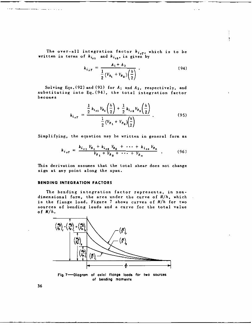
BENDING INTEGRATION FACTORS
The bending integration factor represents, in non-dimensional form, the area under the curve of M/h, which
is the flange load. Figure 7 shows curves of M/h for twosources of bending loads and a curve for the total valueof M/h.
Fig. 7-Diagram of axial flange loads for two sourcesof bending moments
36
The bending integration factor for the curve of (M/h), is
where Al =ý area under curve of (MjVhq),.Similarly, the integration factor for (MR/hR)2 is
k- ~A2 (8
where A2 = area under curve of (Mlh)2.
The total. integration factor is written
kibr ~ AI+A2 (9
Solving Eqs. (97)and (98) for A, and A2, respectively, andsubstituting into Eq.(99), the total integration factor
becomes
Dividing out the wing root thickness hR and simplifying, thetotal integration factor may be written in general as
kibr k ib iMR, + ki 62MR2 + "°" + kib,,MR. (101)
T ~M-91+ MR2 + "'" + MR3
This derivation assumes that the total bending moment doesnot change sign at any point along the span.
37
REFERENCES
1. Shanley, F.R., Structural Weight Analysis-General Method: WingStructures, Project BAND, The RAND Corporation, Report R-100,October 1, 1948.
2. DeYoung, John, Theoretical Additional Span Loading Characteristicsof Wings with Arbitrary Sweep, Aspect Ratio, and Taper Ratio, NACATN 1491, 1947.
3. Sibert, EW.., and P.H. Kemmer, Weight Distribution of Tapered Wings,ACMR STR-51-133, July 28, 1936.
4. Shanley, F.R., "Principles of Structural Design for Minimum Weight,"J. Aeronaut. Sci.. Vol.16, March, 1949, p.1 3 7
39


![MOTORS - Interempresas...Torque conversion factors Moment of inertia conversion factors Conversion Tables NMB-Partnumber BLDC20-OR-GB169 46.1.014 Rated Voltage [V] 12 Rated Speed [rpm]](https://img.pdfslide.us/doc/110x75/608eea873df97d3c1051b823/motors-interempresas-torque-conversion-factors-moment-of-inertia-conversion.jpg)