Embed Size (px)
Citation preview

Project Proposal for Autonomous VehicleGroup Members:
Ramona ConeErin Cundiff
Project Advisors:Dr. Huggins
Dr. IrwinMr. Schmidt
12/12/02

Project Summary
The autonomous vehicle uses an EMAC based system that will autonomously navigatethe vehicle through the Jobst-Baker quad to the destinations entered by the user. Thisvehicle operates under the following conditions:
• The sidewalks in the quad are clear of debris.• The vehicle starts from the same position at the Northeast door of Jobst and is
oriented in the same direction pointing South.
The vehicle navigates from point to point using a table of coordinates stored in EMACmemory that maps the quad. This table of coordinates is based on the various sidewalkintersections located in the quad. Large obstacles, such as people, are detected and thevehicle motion is halted until the obstacle is cleared.

Functional Description
Objectives
The objective of this project is to create an EMAC based system that will autonomouslynavigate a vehicle through the Jobst-Baker quad to the destinations entered by the user.This vehicle operates under the following conditions:
• The sidewalks in the quad are clear of debris.• The vehicle starts from the same position at the Northeast door of Jobst and is
oriented in the same direction pointing South.
The vehicle navigates from point to point using an internal map of the quad stored in theEMAC memory. Large obstacles, such as people, are detected and the vehicle motion ishalted until the obstacle is cleared.
Modes of OperationThis system has three modes of operation: query mode, maneuver mode, and obstaclemode. They are described in detail below.
• Query Mode:The vehicle is stationary, and the user has the opportunity to enter the destinationor destinations of the vehicle. First, the user enters the number of destinations,and then the user enters the destinations in sequential order.
• Maneuver Mode:Straight:The vehicle uses the signals from the sensors to stay on the sidewalk with motionparallel to the edge of the sidewalk. In this mode, no turns are expected and nointersections are detected.Intersection /Lost Edge:The sensors do not detect the edge of the sidewalk, so the vehicle first stops andthen determines from the internal map and the distance input if it is at anintersection. If it is at an intersection, it then enters Turn Mode or re-entersStraight Mode depending on the desired destination. If it is not at an intersection,it searches for the sidewalk edge and re-enters the Straight Mode.Turn:If upon entering an intersection, the vehicle needs to turn to reach the destinationentered by the user, it then enters the Turn Mode from the Intersection /Lost Edgemode. During this mode, the sensors are used to detect when the vehicle hasturned onto the new sidewalk. Once the vehicle is on the intersecting sidewalk,the system steers the vehicle into a straight path parallel to the edge of thesidewalk and enters the Straight Mode. Since the turn radius on the vehicle islarge, the vehicle might have to briefly leave the sidewalk while turning.
• Obstacle Mode:

The vehicle stops when the obstacle detection sensor detects an object within aspecified range. The vehicle waits until the object is no longer detected and thencontinues in its previous mode of operation. Obviously, if the obstacle isstationary, the vehicle will remain stopped, and an information signal will bedisplayed.
System Block Diagram
Figure 1 – Block Diagram
Inputs to EMAC based system:• User Input:
The user picks the final destination and enters the waypoints the vehicle shouldtake. The intersections are identified by number. The user specifies if the tripshould be one-way or round trip. This information is entered on the EMACkeypad.
• Acoustic sensors 1-4 Inputs:Sensors 1, 2, and 3 (see Fig. 2) are mounted on the vehicle pointing towards theground for sidewalk detection inputs. Sensor 4 points straight forward (parallel tothe ground) for an obstacle detection input. Sensors 1, 2, and 3 send signals to theEMAC regarding the surface texture and density. The acoustic sensors 1-3 mayalso be able to send speed information via Doppler shift. Sensor 4 sends a signalto the EMAC if an object is detected within a specified range in front of thevehicle.

Figure 2 – Sensor Diagram on vehicle• Shaft encoder:
This input is a pulse wave proportional to speed and is used by the system todetermine where the vehicle is located on the internal map.
• Linear Actuator:This input sends varying signals according to wheel direction and is used by theEMAC based system to know whether the vehicle is going straight, turning right,or turning left. This information also aids the EMAC based system indetermining the vehicle’s location on the internal map of the quad.
• Digital Electronic Compass:This input sends a signal to the EMAC based system indicating which directionthe vehicle is headed. This information helps the system determine where thevehicle is located on the internal map of the quad.
Output from EMAC based system:• The output of the system is the movement of the vehicle. Either the vehicle is
stopped, or it is moving toward the waypoint specified by the user. The vehicle’smotion towards the waypoint can be seen in three ways: turning right, turning left, orgoing straight. The motion output depends on the various inputs to the EMAC basedsystem.

Input/Output Mode Query Maneuver Obstacle
Acoustic Sensors1-3 N/A
signals vary in amplitudeaccording to surface,
Doppler shift for speedN/A
Acoustic Sensor 4 N/A N/Avarying amplitude signal ifobstacle is detected in the
designed range
Linear Actuator N/A varying signaldetermining wheel angle N/A
Shaft Encoder N/Avarying frequency square
wave proportional tospeed
N/A
Digital ElectronicCompass N/A sends signal according to
direction vehicle is facing N/A
User Input destinations and waypoints N/A N/A
VehicleMovement stopped vehicle turns left, right, or
continues forwardvehicle stops and waits for
obstacle to move
Table 1 - System Inputs and Outputs

System Level Block Diagram for Autonomous Vehicle
Hardware:
Hardware System Level Block Diagram
Figure 3 – Hardware System Level Block Diagram
Each hardware subsystem can be seen in the Hardware System Level Block Diagramabove in Figure 3. This block diagram shows all of the inputs and outputs of eachsubsystem and how they relate to the overall system. Each of the subsystems is discussedin more detail below.
Acoustic Sidewalk Sensor Subsystem
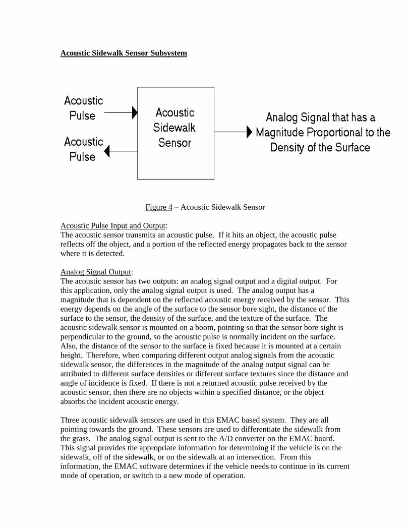
Figure 4 – Acoustic Sidewalk Sensor
Acoustic Pulse Input and Output:The acoustic sensor transmits an acoustic pulse. If it hits an object, the acoustic pulsereflects off the object, and a portion of the reflected energy propagates back to the sensorwhere it is detected.
Analog Signal Output:The acoustic sensor has two outputs: an analog signal output and a digital output. Forthis application, only the analog signal output is used. The analog output has amagnitude that is dependent on the reflected acoustic energy received by the sensor. Thisenergy depends on the angle of the surface to the sensor bore sight, the distance of thesurface to the sensor, the density of the surface, and the texture of the surface. Theacoustic sidewalk sensor is mounted on a boom, pointing so that the sensor bore sight isperpendicular to the ground, so the acoustic pulse is normally incident on the surface.Also, the distance of the sensor to the surface is fixed because it is mounted at a certainheight. Therefore, when comparing different output analog signals from the acousticsidewalk sensor, the differences in the magnitude of the analog output signal can beattributed to different surface densities or different surface textures since the distance andangle of incidence is fixed. If there is not a returned acoustic pulse received by theacoustic sensor, then there are no objects within a specified distance, or the objectabsorbs the incident acoustic energy.
Three acoustic sidewalk sensors are used in this EMAC based system. They are allpointing towards the ground. These sensors are used to differentiate the sidewalk fromthe grass. The analog signal output is sent to the A/D converter on the EMAC board.This signal provides the appropriate information for determining if the vehicle is on thesidewalk, off of the sidewalk, or on the sidewalk at an intersection. From thisinformation, the EMAC software determines if the vehicle needs to continue in its currentmode of operation, or switch to a new mode of operation.

Acoustic Obstacle Sensor Subsystem
Figure 5 – Acoustic Obstacle Sensor
Acoustic Pulse Input and Output:The acoustic sensor transmits an acoustic pulse. If it hits an object, the acoustic pulsereflects off the object, and a portion of the reflected energy propagates back to the sensorwhere it is detected.
TTL Signal Output:The acoustic sensor has two outputs: an analog signal output and a digital output. Forthis application, only the digital signal output is used. The digital output is generated if areturn pulse is detected. If detected, the time delay of the pulse relative to transmissiontime is proportional to the distance of the object to the sensor. The detection of theacoustic pulse depends on the angle of the surface to the sensor bore sight, the distance ofthe surface to the sensor, the density of the surface, and the texture of the surface. Thus,larger objects will return an acoustic pulse at larger distances than smaller objects. Also,objects with a surface normal to the acoustic pulse will return an acoustic pulse at largerdistances than objects with a surface not normal to the acoustic pulse.
There is one acoustic obstacle sensor mounted on the top of the vehicle pointing straightforward. Unless there is an obstacle within the specified range, the TTL signal output iszero. If an obstacle is detected, the output goes high with the delay proportional to thedistance to the obstacle. Since a pulse train is transmitted, the echo output is periodic andhas a higher frequency for closer objects, and a lower frequency for objects farther away.This TTL signal is sent to the EMAC board to determine if there is an obstacle in front ofthe vehicle. If the TTL signal indicates that an object is within a certain distance, thevehicle will enter obstacle mode and stop. The vehicle will remain stopped until the TTLsignal indicates that the obstacle is gone, and then the vehicle will reenter its previousmode of operation.

Digital Compass Subsystem
Figure 6 – Digital Compass
Compass Heading Input:The compass, attached to the vehicle, responds to heading of the vehicle.
Serial or Parallel Signal Output:It is assumed that there is a correlation between the compass’ heading (and thereforevehicle heading) to electronic output of the compass. Obviously, more investigationneeds to be done to determine the nature of the outputs and compatibility with inputs tothe EMAC. This output is sent to the EMAC board where it is interpreted as the directionof the vehicle in degrees relative to North. This computed direction of the vehicle is usedby the EMAC to aid in determining where the vehicle is heading on the internal map ofthe Jobst-Baker quad.

Shaft Speed Encoder Subsystem
Figure 7 – Shaft Speed Encoder
Rotation of Axle Input:This input is the rotation of the axle that spins a disk. A clear disk is attached to the axlewith opaque markings on it. The rotation of the axle causes the disk to spin.
TTL Signal Output:The TTL signal output has a frequency that is proportional to the RPM of the shaft. Anopto-isolator is used to produce the output signal. Every time an opaque mark reaches asensor the opto-isolator pulses. More investigation needs to be done to determine thenumber of opaque markings needed to make an accurate calculation of vehicle speed. Iffour opaque markings are used, for example, then after every fourth pulse, the axle hasmade one complete revolution. The output frequency is therefore proportional to theRPM of the shaft. The higher the frequency means the faster the rotation of the axle.The faster the rotation of the axle means the faster the vehicle is traveling.
This TTL signal is sent to the EMAC board. The EMAC software uses the output of thissubsystem to determine the speed of the vehicle, which in turn, allows distance traversedto be determined. From the distance the vehicle has traveled, the software is able todetermine where the vehicle is on the internal map.
Linear Actuator Subsystem
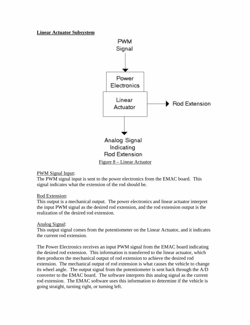
Figure 8 – Linear Actuator
PWM Signal Input:The PWM signal input is sent to the power electronics from the EMAC board. Thissignal indicates what the extension of the rod should be.
Rod Extension:This output is a mechanical output. The power electronics and linear actuator interpretthe input PWM signal as the desired rod extension, and the rod extension output is therealization of the desired rod extension.
Analog Signal:This output signal comes from the potentiometer on the Linear Actuator, and it indicatesthe current rod extension.
The Power Electronics receives an input PWM signal from the EMAC board indicatingthe desired rod extension. This information is transferred to the linear actuator, whichthen produces the mechanical output of rod extension to achieve the desired rodextension. The mechanical output of rod extension is what causes the vehicle to changeits wheel angle. The output signal from the potentiometer is sent back through the A/Dconverter to the EMAC board. The software interprets this analog signal as the currentrod extension. The EMAC software uses this information to determine if the vehicle isgoing straight, turning right, or turning left.

Motor Subsystem
Figure 9 – Motor
On/Off Signal Input:This input turns the motor on or turns the motor off.
DC Supply Input:This input comes from the DC battery supply. It provides the motor with the appropriateDC voltage to operate.
Torque Output:The torque output is a mechanical output produced by the motor.
The EMAC board sends an on/off input signal to the motor. When the motor is on, themotor produces a mechanical output. This mechanical output is torque, and it is appliedto the appropriate gearing on the axle to turn the wheels of the vehicle. When the EMACbased system is in query mode or obstacle mode, the EMAC sends a signal to the motorindicating that the motor should be off. When the EMAC based system is in themaneuver mode, it sends a signal to the motor indicating that the motor should be on.

KeypadInput?
Call StraightMode
Done?
Coordinatesloaded?
Y
Y
N
Initialize EMAC
Display ChoicePrompt
Load Coordinates
Y
N
Gather thresholdvalues
N
Software:
Query Mode
Before entering query mode, it is assumed that all components are initialized andsystem is ready for operation.
Figure 10 – Query mode flowchart
In Query mode, after the waypoint prompt is displayed, the microprocessor will wait forinput from the user. After initial input, the microprocessor will check for a ‘Done’ input.If no ‘Done’ is detected, the current waypoint will be stored and a prompt for more pointswill be displayed on the LCD. Once a ‘Done’ input has been detected, themicroprocessor checks to verify that waypoints were entered. If no points were enteredthe software will return and prompt the user for a waypoint. Otherwise, themicroprocessor will gather a collection of 10 data points from the grass sonar and 10 datapoints from the concrete sonar to create an average threshold value to compare withfuture sonar readings. Once the threshold value is computed the Straight routine will becalled by the microprocessor.
Maneuver Mode
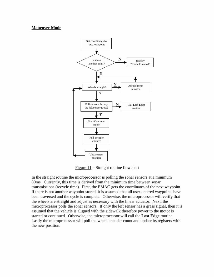
Figure 11 – Straight routine flowchart
In the straight routine the microprocessor is polling the sonar sensors at a minimum80ms. Currently, this time is derived from the minimum time between sonartransmissions (recycle time). First, the EMAC gets the coordinates of the next waypoint.If there is not another waypoint stored, it is assumed that all user-entered waypoints havebeen traversed and the cycle is complete. Otherwise, the microprocessor will verify thatthe wheels are straight and adjust as necessary with the linear actuator. Next, themicroprocessor polls the sonar sensors. If only the left sensor has a grass signal, then it isassumed that the vehicle is aligned with the sidewalk therefore power to the motor isstarted or continued. Otherwise, the microprocessor will call the Lost Edge routine.Lastly the microprocessor will poll the wheel encoder count and update its registers withthe new position.
Is thereanother point?
Poll sensors; is onlythe left sensor grass?
Wheels straight?
Get coordinates fornext waypoint
Y
N
Display“Route Finished”
Call Lost Edgeroutine
Start/Continuemotor
Poll encodercounter
Update newposition
Y
N
Y
N Adjust linearactuator

Compare dest inat ion waypoint with current
position
Poll sensors; all 3 concrete?
Adjust wheels for left turn
Adjust wheels for right turn
poll sensors; left one grass?
poll compass; heading correct?
Determine and make wheel adjustment
poll sensors; left one grass?
Turn here? Are they equal? Call turn rout ine
No adjustments to wheels
Return to st raight rout ine
Y
Y Y
Y
Y Y
N
N
N
N N
N
Figure 12 – Lost Edge routine flowchart
In the Lost Edge routine will compare the current coordinates of the vehicle with thecoordinates the desired waypoint vehicle as entered by the user. If the two sets ofcoordinates are equal, then the microprocessor will check if a turn is necessary at thisway point. If a turn is required at this way point the Turn routine will be called (seeFigure 13) by the microprocessor. Otherwise, the EMAC will continue moving forwardwith the wheels straight until grass is detected on the left sonar sensor. If the coordinatesare not equal than the vehicle has lost alignment with the sidewalk and needs to berealigned. To correct alignment the microprocessor will poll the sonar sensors anddetermine if all three sensors are over concrete. If this is true, then the wheels should beadjusted for a left turn and right otherwise. At this point the microprocessor will continueto poll the sonar sensors until a grass signal is detected on the left sensor. Once thisoccurs, the microprocessor will poll the compass and compare this value with storedheading to verify proper heading of vehicle. If the vehicle has a correct heading, then themicroprocessor will return to the Straight routine. Otherwise, the necessary headingcorrection will be determined and the linear actuator adjusted accordingly. Themicroprocessor will poll the sonar sensors to ensure that the vehicle’s left sensor is stillon grass. If the left sensor is no longer on grass then the microprocessor returns to theearlier function that acquires the grass edge. Otherwise, the compass will be polled torecheck the vehicle’s heading and repeat this process until the heading is correct and the

left sensor is on grass. At this point the Lost Edge routine returns to the Straightroutine.
Figure 13 – Turn routine
This routine is called by the Lost Edge routine. After the desired direction is determinedby the microprocessor, it sends the appropriate signal to the actuator. Themicroprocessor will poll the compass and wait for the a predetermined heading to bereached. Afterwards, the microprocessor will poll the sonar modules and wait for allthree to be concrete of signals. Once this set of signals is acquired, the sonar moduleswill be polled until only the left sonar has a grass signal. Then, the routine will checkthe heading of the digital compass and compare it to a stored value for this intersection.If the heading is correct, the vehicle is aligned with the sidewalk and is ready to return tothe Straight routine. Otherwise, a calculated wheel adjustment is made. Then thecompass and sonar sensors are polled until the vehicle is aligned.
Send left signalto actuator
Whichdirection?
Send right signalto actuator
Poll compass;heading correct?
Poll sensors; all 3concrete?
Left sonar sensorgrass?
Poll compass;heading correct?
Return toStraight routine
Determine and makewheel adjustment
Left sonarsensor grass?
Poll sensors; all3 concrete?
Send left signalto actuator
Send right signalto actuator
Y Y
Y
YY
N
N
NN
N
Y
N
L
R

Obstacle Mode
Figure 14 – Obstacle mode flowchart
This mode will be interrupt driven. One sonar module mounted parallel with the groundwill determine if there are any objects in the vehicle’s path. If an object is detected, theinterrupt routine will be called. This routine will halt any further movement until theobject is removed or the vehicle is placed at start and reset.
Objectdetected?
Stop all signals to motorand actuator
Allow active actuator andmotor signals
N
Y

Patents
There are several patents that have some similarities to this project, but none of thepatents use sonar sensors to help navigate the autonomous vehicle. The associatedpatents are listed below.
• “System and Method for Causing an Autonomous Vehicle to Track a Path”• U.S. Patent 5,657,226 August 12,1997• Integrated vehicle positioning and navigation• Combination of apparatus and methods• Included GPS and an IRU (inertial reference unit)• Position calculations and vehicle control with obstacle detection
• “Autonomous Vehicle Arrangement and Method for Controlling an AutonomousVehicle”• U.S. Patent 6,151,539 November 21,2000• System includes• Input of travel orders• Digital map• Path generating unit• Laser and radar sensors for detecting obstacles and condition of path
• “Autonomous Vehicle Capable of Traveling/Stopping in Parallel to Wall”• U.S Patent 6,038,501 March 14,2000• Wheel encoder for distance and speed• Gyro for detecting direction
• “System and a Method for Enabling a Vehicle to Track a Present Path”• U.S. Patent 5,838,562 November 17,1998• GPS & IRU• Remote Control
• “System and Method for Enabling an Autonomous Vehicle to Track a Desired Path”• U.S. Patent 5,684,696 November 4, 1997• Plans a continuous path and return path if vehicle deviates from desired path• GPS & IRU

DATA SHEET
Specifications for each mode of operation will be discussed in this section. Also, thetesting procedures to show that the autonomous vehicle is working will be discussed.
• Specifications for Query Mode• There will be a user interface that consists of a keypad and LCD display.• The vehicle is stationary during this mode. The user is prompted to enter the
destination or destinations of the vehicle. First, the user enters the number ofdestinations, and then the user enters the destinations in sequential order.
• The user can enter up to 15 waypoints (or destinations).
• Specifications for Maneuver Mode• In the Straight Sub-mode:
• The position calculation of the vehicle on the internal map of the quad will bewithin +/- 0.5 meters of the vehicle’s actual position.
• The maximum speed of the vehicle is 2.24 meters/second.• For this project, the vehicle will travel at a constant speed of
0.25 meters/second.• The deviation of the vehicle from the sidewalk edge will be no more than
10 centimeters.• In the Intersection/Lost Edge Sub-mode:
• If the edge of the sidewalk is lost, but the position of the vehicle does notmatch the location of an intersection on the internal map, the vehicle will have5 seconds to reacquire the edge of the sidewalk.
• If the edge of the sidewalk is not reacquired, the vehicle will stop, and it mustbe reset by the user.
• In the Turn Sub-mode:• The minimum turn radius is 10 ft.• It will take 5 seconds for the vehicle to acquire the straight sub-mode after a
90° turn has been made.
• Specifications for Obstacle Mode• Detection Zone
• Objects are detected between 3 and 7 meters.• Alarm Zone
• An alarm will sound if objects are detected between 1 and 3 meters, whichwill warn the obstacle that the vehicle is coming.
• Stop Zone• The vehicle will stop if an object is detected between 0 and 1 meters.• After the vehicle has stopped, it will wait for the object to move, and then it
will continue in its previous mode of operation.• If the object does not move, the vehicle must be reset by the user.

• Testing of Autonomous Vehicle• Test 1 (Tests Straight Sub-mode):
• Run the vehicle from the starting point to the first waypoint, and then have itstop.
• Test 2 (Tests Lost Edge/Intersection Sub-mode):• Start the vehicle at an angle on the sidewalk where there is not an intersection.
The angle will force the vehicle to lose the sidewalk edge. This test willshow if the vehicle can reacquire the edge of the sidewalk within 5 seconds, orif the vehicle will stop if it does not reacquire the edge of the sidewalk within5 seconds.
• Test 3 (Tests the Turn Sub-mode):• Run the vehicle to the first two waypoints and then have it stop. The vehicle
will have to turn to reach the second waypoint.• Test 4 (Tests the Obstacle Mode):
• Run the vehicle with an object in front of it to see if the alarm goes off and thevehicle stops.

Preliminary Work
• Experimented with Acoustic Sensor• Took Measurements from Acoustic Sensor for different surface textures (sidewalk,
grass, etc).• Examined Shaft Speed Encoder• Learned about Digital Compass• Worked on Power Electronics for Linear Actuator• Worked on Design for the Power Electronics for the Motor
Figure 15 – Sensor Output in Figure 16 – Sensor Output inResponse to Grass Response to Concrete
As can be seen in figure 15 and figure 16, there is a 230 mV difference in the magnitudebetween grass and concrete. This is a large enough difference to distinguish betweengrass and concrete.

Schedule and Division of Labor
Table 2 – Schedule of Tasks
Erin Cundiff Ramona ConeHardware: Acoustic Sidewalk Sensors Hardware: Linear Actuator
Acoustic Obstacle Detection Sensor MotorShaft Speed Encoder Digital Compass
Software: Acoustic Sidewalk Sensor Software Software: Linear Actuator SoftwareAcoustic Obstacle Sensor Software Motor Software
Obstacle Mode Digital Compass SoftwareQuery Mode Turn Mode
Straight Mode Lost Edge ModeQuad Map
Table 3 – Division of Labor

Equipment List
• Acoustic Sensors• Sensors for Shaft Speed Encoder
• Preliminary Design includes Hall Effect Sensors• Digital Compass• EMAC board with Keypad and LCD display• H-Bridge Chip• Motor and Linear Actuator• Vehicle and Battery

Bibliography
Beetz, M., S. Buck, R. Hanek, B. Radig, and T. Schmitt. "Cooperative Probabilistic StateEstimation for Vision-Based Autonomous Mobile Robots.” IEEE Transactions onRobots and Automation, vol.18, no. 5, p. 670, October 2002.
Clark, S., M. Csorba, M. W. M. Gamini Dissanayake, H. F. Durrant-Whyte, and P.Newman. "A Solution to the Simultaneous Localization and Map BuildingProblem.” IEEE Transactions on Robots and Automation, vol.17, no. 3, p. 229,June 2001.
Heber, T., N. C. Txourveloudis, and K.P. Valavanis. "Autonomous Vehicle NavigationUtilizing Electrostatic Potential Fields and Fuzzy Logic.” IEEE Transactions onRobots and Automation, vol.17, no. 4, p. 490, August 2001.
Jacobsen, S., P. Pederson, and J. Willhjelm. "The Influence of Roughness, Angle, Range,and Transducer Type on the Echo Signal from Planar Interface.” IEEETransactions on Ultrasonics, Ferroelectrics, and Frequency Control, vol. 48, no. 2,p. 511, March 2001.
Laiv, A. "Adaptive Output Regulation of Robot Manipulates under ActuatorConstraints.” IEEE Transactions on Robots and Automation, vol.16, no. 1, p. 29,February 2000.