Embed Size (px)
Citation preview

Project Olympus 2U Server Mechanical
Specification
Author:
Anand Kulkarni, Senior Mechanical Engineer, Microsoft

Open Compute Project • Project Olympus 2U Server Mechanical Specification
ii November 1, 2017
Revision History
Date Description
11/1/2017 Version 1.0 Ready for Project Olympus github

Open Compute Project • Project Olympus 2U Server Mechanical Specification
http://opencompute.org iii
© 2017 Microsoft Corporation.
As of November 1, 2017, the following persons or entities have made this Specification available under the Open Web
Foundation Final Specification Agreement (OWFa 1.0), which is available at http://www.openwebfoundation.org/legal/the-owf-
1-0-agreements/owfa-1-0
Microsoft Corporation.
You can review the signed copies of the Open Web Foundation Agreement Version 1.0 for this Specification at Project Olympus License Agreements, which may also include additional parties to those listed above.
Your use of this Specification may be subject to other third party rights. THIS SPECIFICATION IS PROVIDED "AS IS." The
contributors expressly disclaim any warranties (express, implied, or otherwise), including implied warranties of merchantability,
non-infringement, fitness for a particular purpose, or title, related to the Specification. The entire risk as to implementing or
otherwise using the Specification is assumed by the Specification implementer and user. IN NO EVENT WILL ANY PARTY BE LIABLE
TO ANY OTHER PARTY FOR LOST PROFITS OR ANY FORM OF INDIRECT, SPECIAL, INCIDENTAL, OR CONSEQUENTIAL DAMAGES OF
ANY CHARACTER FROM ANY CAUSES OF ACTION OF ANY KIND WITH RESPECT TO THIS SPECIFICATION OR ITS GOVERNING
AGREEMENT, WHETHER BASED ON BREACH OF CONTRACT, TORT (INCLUDING NEGLIGENCE), OR OTHERWISE, AND WHETHER OR
NOT THE OTHER PARTY HAS BEEN ADVISED OF THE POSSIBILITY OF SUCH DAMAGE.
CONTRIBUTORS AND LICENSORS OF THIS SPECIFICATION MAY HAVE MENTIONED CERTAIN TECHNOLOGIES THAT ARE MERELY
REFERENCED WITHIN THIS SPECIFICATION AND NOT LICENSED UNDER THE OWF CLA OR OWFa. THE FOLLOWING IS A LIST OF
MERELY REFERENCED TECHNOLOGY: INTELLIGENT PLATFORM MANAGEMENT INTERFACE (IPMI); I2C IS A TRADEMARK AND
TECHNOLOGY OF NXP SEMICONDUCTORS ; EPYC IS A TRADEMARK AND TECHNOLOGY OF ADVANCED MICRO DEVICES INC.; ASPEED
AST 2400/2500 FAMILY PROCESSORS IS A TECHNOLOGY OF ASPEED TECHNOLOGY INC.; MOLEX NANOPITCH, NANO PICOBLADE,
AND MINI-FIT JR AND ASSOCIATED CONNECTORS ARE TRADEMARKS AND TECHNOLOGIES OF MOLEX LLC; WINBOND IS A
TRADEMARK OF WINBOND ELECTRONICS CORPORATION; NVLINK IS A TECHNOLOGY OF NVIDIA; INTEL XEON SCALABLE
PROCESSORS, INTEL QUICKASSIST TECHNOLOGY, INTEL HYPER-THREADING TECHNOLOGY, ENHANCED INTEL SPEEDSTEP
TECHNOLOGY, INTEL VIRTUALIZATION TECHNOLOGY, INTEL SERVER PLATFORM SERVICES, INTEL MANAGABILITY ENGINE, AND
INTEL TRUSTED EXECUTION TECHNOLOGY ARE TRADEMARKS AND TECHNOLOGIES OF INTEL CORPORATION; SITARA ARM CORTEX-
A9 PROCESSOR IS A TRADEMARK AND TECHNOLOGY OF TEXAS INSTRUMENTS; GUIDE PINS FROM PENCOM; BATTERIES FROM
PANASONIC. IMPLEMENTATION OF THESE TECHNOLOGIES MAY BE SUBJECT TO THEIR OWN LEGAL TERMS.
iv November 1, 2017
Contents 1 Project Olympus Specification List ................................................................................................................. 5
2 Overview ....................................................................................................................................................... 5
3 Background ................................................................................................................................................... 6
4 Server Features ............................................................................................................................................. 6
4.1 Front Panel ................................................................................................................................................... 7
4.2 Rear Panel .................................................................................................................................................... 7
4.3 PSU ............................................................................................................................................................... 8
4.4 Fans .............................................................................................................................................................. 8
5 Electromagnetic Interference Mitigation ........................................................................................................ 8
5.1 Grounding and Return .................................................................................................................................. 9
6 Physical Specification ..................................................................................................................................... 9
7 Environmental ............................................................................................................................................. 10
Table of Figures Figure 1. 2U Server Example ............................................................................................................................... 6
Figure 2. Front Panel ..................................................................................................................................... 7
Figure 3. Rear Panel....................................................................................................................................... 8
Figure 4. 2U Server Dimensions. Top cover omitted for clarity ................................................................... 10
Table of Tables Table 1: List of Specifications ........................................................................................................................ 5
Table 2. Environmental Requirement.......................................................................................................... 11

Open Compute Project • Project Olympus 2U Server Mechanical Specification
http://opencompute.org v
1 Project Olympus Specification List
Table 1 lists the Project Olympus system specifications.
Table 1: List of Specifications
Specification title Description
Project Olympus Server Rack Specification
Describes the mechanical rack hardware used in the system
Project Olympus Server Mechanical Specification
Describes the mechanical structure for the server used in the system.
Project Olympus Server Motherboard Specification
Describes the server motherboard general requirements.
Project Olympus PSU Specification Describes the custom Power Supply Unit (PSU) used in the server
Project Olympus Power Management Distribution Unit Specification
Describes the Power Management Distribution Unit (PMDU).
Project Olympus Rack Manager Specification
Describes the Rack Manager PCBA used in the PMDU.
This document is intended for designers and engineers who will be building servers for Project Olympus
systems.
2 Overview
This specification focuses on the Project Olympus 2U server mechanical assembly. It covers the
mechanical features and supported components of the server, as well as the interfaces with the
mechanical and power support structure. An example of a 2U server is shown in Figure 1.
Refer to respective specifications for other elements of Project Olympus such as Power Supply Unit (PSU),
Rack Manager (RM), Power and Management Distribution Unit (PMDU), Server Motherboard, and Rack.

vi November 1, 2017
Figure 1. 2U Server Example
3 Background
To conceptualize how the server motherboard fits within the rack, consider the following.
The server motherboard is the computational element of the server. The motherboard includes a full
server management solution and supports interfaces to an integrated or a set of rear-access 12V Power
Supply Units (PSUs).
The server optionally interfaces a rack-level Power and Management Distribution Unit (PMDU).
The PMDU provides power to servers and interfaces to the Rack Manager (RM).
The motherboard design provides optimum front-cable access (cold aisle) for external IO such as
networking and storage as well as standard PCIe cards. This enables flexibility to support many
configurations.
4 Server Features
The following is a list of the primary features supported by the motherboard.
Open Compute Project • Project Olympus 2U Server Mechanical Specification
Httep://opencompute.org vii
• Support full rack width, 2U height (3.50 inches), server assembly
• Supports blind-mate power with Project Olympus Rack with PMDU
• Supports Project Olympus Server Motherboard
• Supports up to three FHHL x16 Gen3 PCIe Cards.
• Supports cold aisle cabling for I/O and Ethernet management
• Supports cold aisle servicing (VGA + USB 3.0)
• Supports integrated Project Olympus PSU
• Supports up to 12 SATA devices
• Supports 12 (N+2) non hot-swap 40mm fans*
• Supports optional remote heat sink for high power processors
*Microsoft implementation uses 10 non hot swap 40 mm fans.
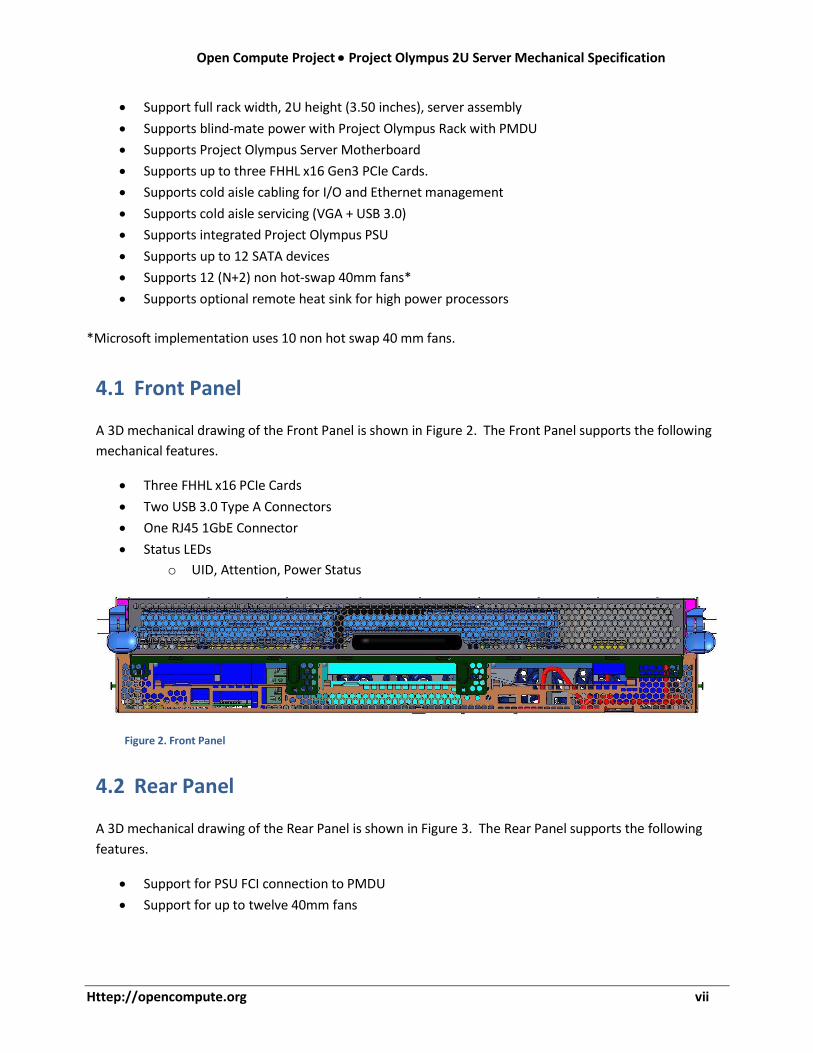
4.1 Front Panel
A 3D mechanical drawing of the Front Panel is shown in Figure 2. The Front Panel supports the following
mechanical features.
• Three FHHL x16 PCIe Cards
• Two USB 3.0 Type A Connectors
• One RJ45 1GbE Connector
• Status LEDs
o UID, Attention, Power Status
Figure 2. Front Panel
4.2 Rear Panel
A 3D mechanical drawing of the Rear Panel is shown in Figure 3. The Rear Panel supports the following
features.
• Support for PSU FCI connection to PMDU
• Support for up to twelve 40mm fans

viii November 1, 2017
Figure 3. Rear Panel
4.3 PSU
The server assembly shall support up to two Project Olympus PSUs with optional battery. Additional
information can be found in the Project Olympus PSU Specification.
4.4 Fans
The server is required to use on-board fans to cool the electrical components. A maximum of six 40mm
fans may be used to cool the components in a single U, with a maximum of twelve 40mm fans* in a 2U
server configuration. The maximum airflow allowed in a server must not exceed 158 CFM/kW. The
server must also operate at its maximum power configuration without performance degradation with 2
failed fans in a single 1U zone. The fans are N+2 redundant to optimize fan efficiency and server
availability while eliminating the need for hot swap capability.
The fans shall be variable speed and shall be controlled by the BMC on the server motherboard.
Variable fan speed capability allows the rack to minimize energy consumption of the air movers and
facilities in conditions that permit it. The speed of airflow is based on component temperature
requirements within the server. The server has provisions for 2 airflow zones. One zone for 1U and the
second zone for 2U.
*Microsoft implementation uses 10 non hot swap 40 mm fans.
5 Electromagnetic Interference Mitigation
For electromagnetic interference (EMI) containment, EMI shielding and grounding must be accounted
for at the server assembly level. All servers must support a top cover that fits within the U envelope to
prevent leakage of electromagnetic fields and airflow.

Open Compute Project • Project Olympus 2U Server Mechanical Specification
http://opencompute.org ix
5.1 Grounding and Return
The server chassis grounding/return is provided to the motherboard from the tray assembly through the
alignment and mounting holes that secure the motherboard to the tray. The motherboard is also tied to
the PSU ground through the 12V power connector. Chassis ground and Logic ground are tied together
on the motherboard.
6 Physical Specification
Figure 4 depicts the overall dimensions of the server assembly. The front of the chassis (cold aisle) is on
the right. Shown are locations of three PCIe x16 slots on the motherboard as a reference for other
motherboards. For detailed mechanical information including mounting hole location and dimensions,
please reference Project Olympus mechanical data package and the Server Motherboard Specification.
The total mass of a populated server must not exceed 75 lbs to meet datacenter handling requirements.
Server mechanical stiffness shall be high enough to tolerate general handling and racking ability w/o
damage to or interference with other components when fully populated.

x November 1, 2017
Figure 4. 2U Server Dimensions. Top cover omitted for clarity.
7 Environmental
The server is to be deployed in an environmentally controlled location. The inlet to the server will be
exposed to the environment described in Table 2. The server must have the capability to provide full
functional operation under the conditions provided.

http://opencompute.org xi
Open Compute Project • Project Olympus 2U Server Mechanical Specification
Table 2. Environmental Requirement
Specification Requirement
Inlet temperature
Operating
• 50°F to 95°F (10°C to 35°C)
• Maximum rate of change: 18°F (10°C)/hour
• Allowable derating guideline of 1.6°F/1000ft (0.9°C/304m)
above 3000 ft.
Non-operating • -40°F to 140°F (-40°C to 60°C)
• Rate of change less than 36°F (20°C)/hour
Acoustic Less than 6.8 bells at maximum fan speed operating condition
Non-Operational
Shock and Vibration
The server must be capable of rack level transportation via common carrier. Rack
level testing to comply with ASTM 4169.
Recommended levels for a single server in a fixture to simulate installation in a
rack:
• Shock – Half sine, 10G, 5m/s
• Vibration – 1.146 Grms, 1 hour


![Cambridge HSC Maths [2U]](https://img.pdfslide.us/doc/110x75/55cf904f550346703ba4bad1/cambridge-hsc-maths-2u.jpg)