Embed Size (px)
Citation preview
Project NSF H54UProject NSF H54U
A photo report from an little old historical radio.Problems and solutions at restoration.
introduction
Part 1 restauration of the cabinet
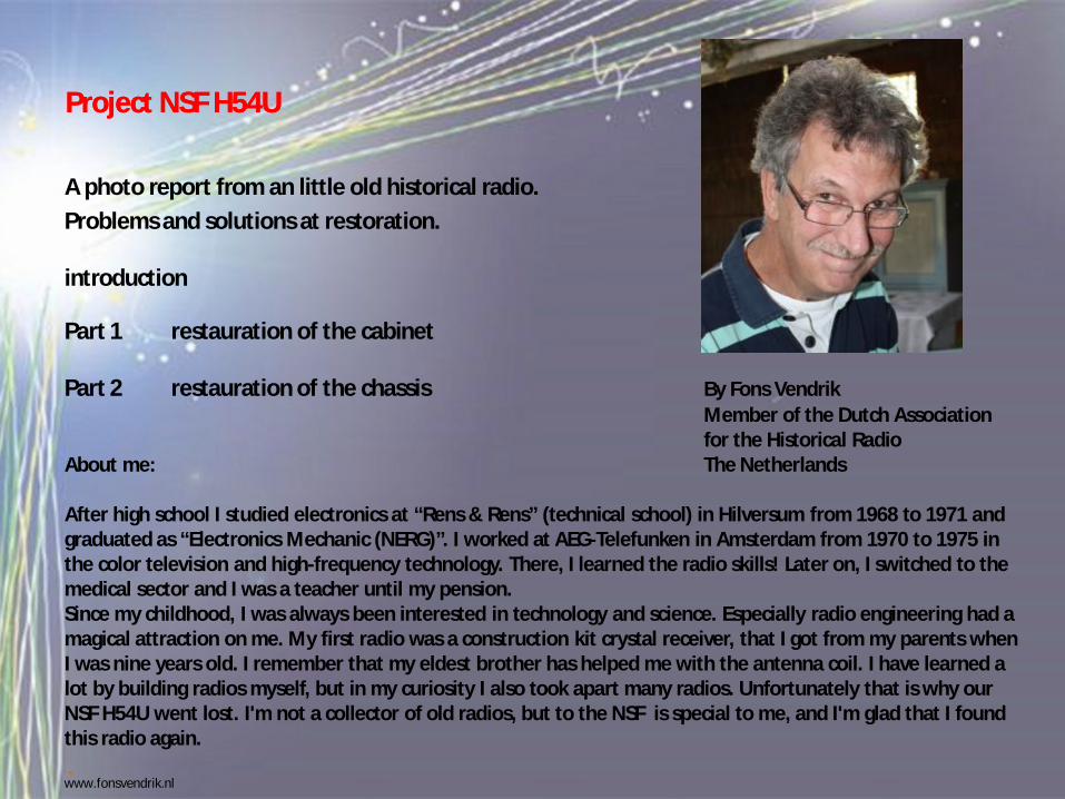
Part 2 restauration of the chassis By Fons VendrikMember of the Dutch Associationfor the Historical Radio
About me: The Netherlands
After high school I studied electronics at “Rens & Rens” (technical school) in Hilversum from 1968 to 1971 and graduated as “Electronics Mechanic (NERG)”. I worked at AEG-Telefunken in Amsterdam from 1970 to 1975 in the color television and high-frequency technology. There, I learned the radio skills! Later on, I switched to the medical sector and I was a teacher until my pension.Since my childhood, I was always been interested in technology and science. Especially radio engineering had a magical attraction on me. My first radio was a construction kit crystal receiver, that I got from my parents when I was nine years old. I remember that my eldest brother has helped me with the antenna coil. I have learned a lot by building radios myself, but in my curiosity I also took apart many radios. Unfortunately that is why our NSF H54U went lost. I'm not a collector of old radios, but to the NSF is special to me, and I'm glad that I found this radio again.
www.fonsvendrik.nl
Project NSF H54U part 1Project NSF H54U part 1
introduction
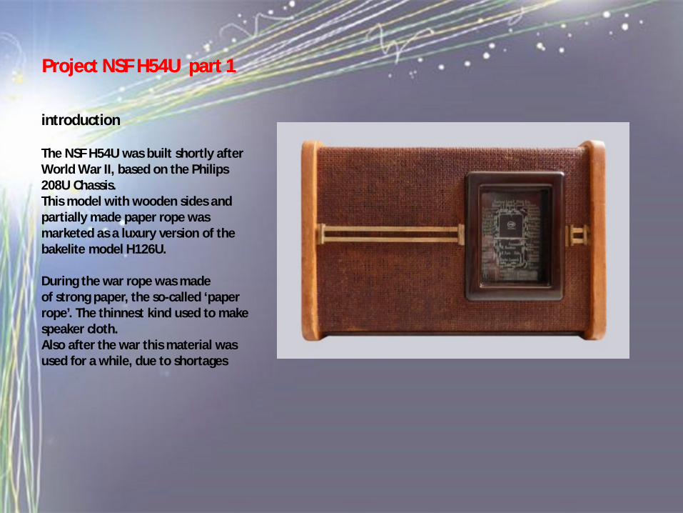
The NSF H54U was built shortly afterWorld War II, based on the Philips 208U Chassis.This model with wooden sides and partially made paper rope was marketed as a luxury version of the bakelite model H126U.
During the war rope was madeof strong paper, the so-called ‘paper rope’. The thinnest kind used to make speaker cloth.Also after the war this material was used for a while, due to shortages
Project NSF H54UProject NSF H54U
introduction
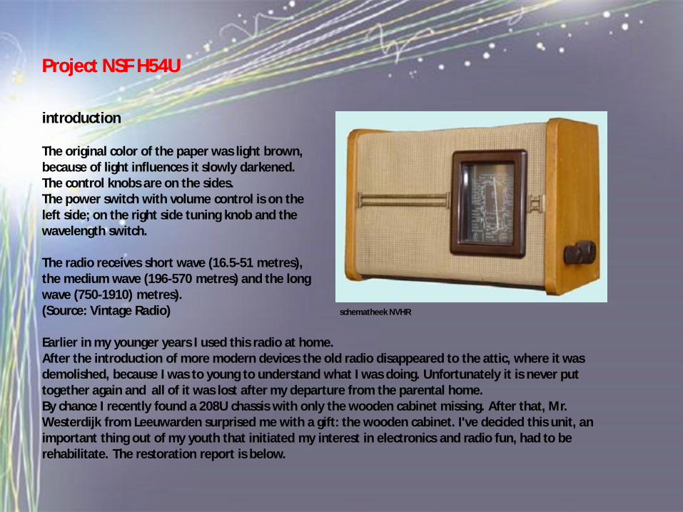
The original color of the paper was light brown,because of light influences it slowly darkened. The control knobs are on the sides.The power switch with volume control is on theleft side; on the right side tuning knob and thewavelength switch.
The radio receives short wave (16.5-51 metres),the medium wave (196-570 metres) and the longwave (750-1910) metres).(Source: Vintage Radio) schematheek NVHR
Earlier in my younger years I used this radio at home.After the introduction of more modern devices the old radio disappeared to the attic, where it was demolished, because I was to young to understand what I was doing. Unfortunately it is never put together again and all of it was lost after my departure from the parental home.By chance I recently found a 208U chassis with only the wooden cabinet missing. After that, Mr. Westerdijk from Leeuwarden surprised me with a gift: the wooden cabinet. I've decided this unit, an important thing out of my youth that initiated my interest in electronics and radio fun, had to be rehabilitate. The restoration report is below.
Project NSF H54UProject NSF H54U
The cabinet and chassis
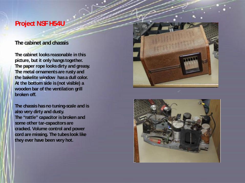
The cabinet looks reasonable in this picture, but it only hangs together.The paper rope looks dirty and greasy. The metal ornaments are rusty and the bakelite window has a dull color. At the bottom side is (not visible) a wooden bar of the ventilation grill broken off.
The chassis has no tuning-scale and is also very dirty and dusty.The “rattle” capacitor is broken and some other tar-capacitors are cracked. Volume control and power cord are missing. The tubes look like they ever have been very hot.
Project NSF H54UProject NSF H54U
The tuning-scale
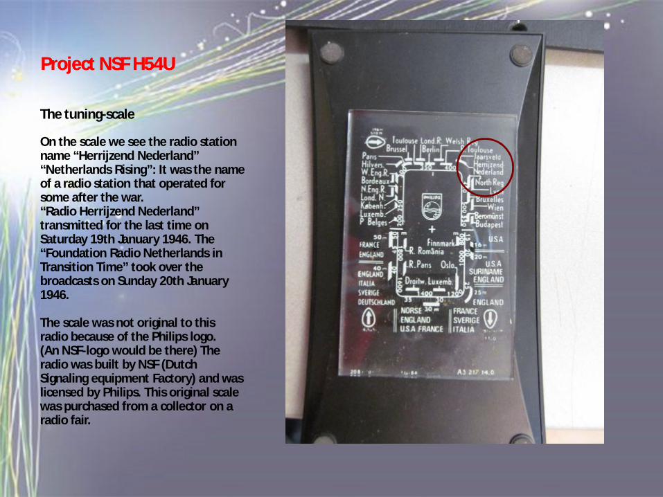
On the scale we see the radio station name “Herrijzend Nederland”“Netherlands Rising”: It was the nameof a radio station that operated for some after the war.“Radio Herrijzend Nederland” transmitted for the last time on Saturday 19th January 1946. The “Foundation Radio Netherlands in Transition Time” took over the broadcasts on Sunday 20th January 1946.
The scale was not original to this radio because of the Philips logo.(An NSF-logo would be there) The radio was built by NSF (Dutch Signaling equipment Factory) and was licensed by Philips. This original scale was purchased from a collector on a radio fair.
Project NSF H54UProject NSF H54U
The cabinet in parts
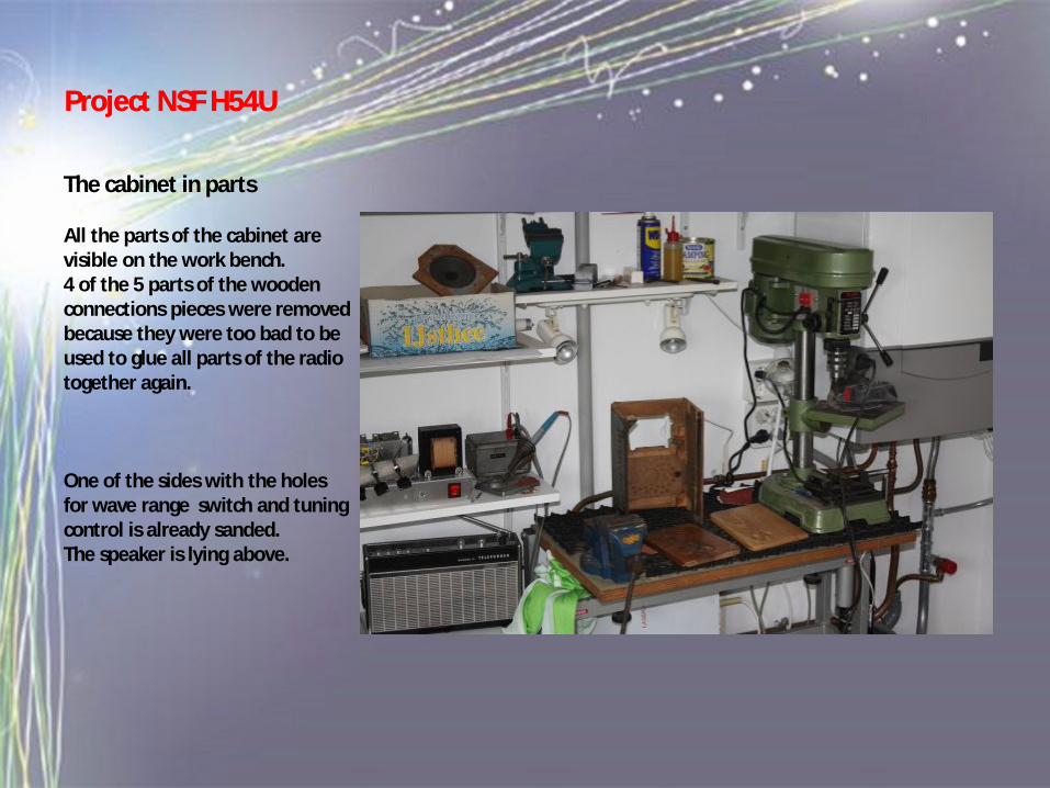
All the parts of the cabinet are visible on the work bench.4 of the 5 parts of the wooden connections pieces were removed because they were too bad to be used to glue all parts of the radio together again.
One of the sides with the holesfor wave range switch and tuning control is already sanded.The speaker is lying above.
Project NSF H54UProject NSF H54U
The cabinet in parts
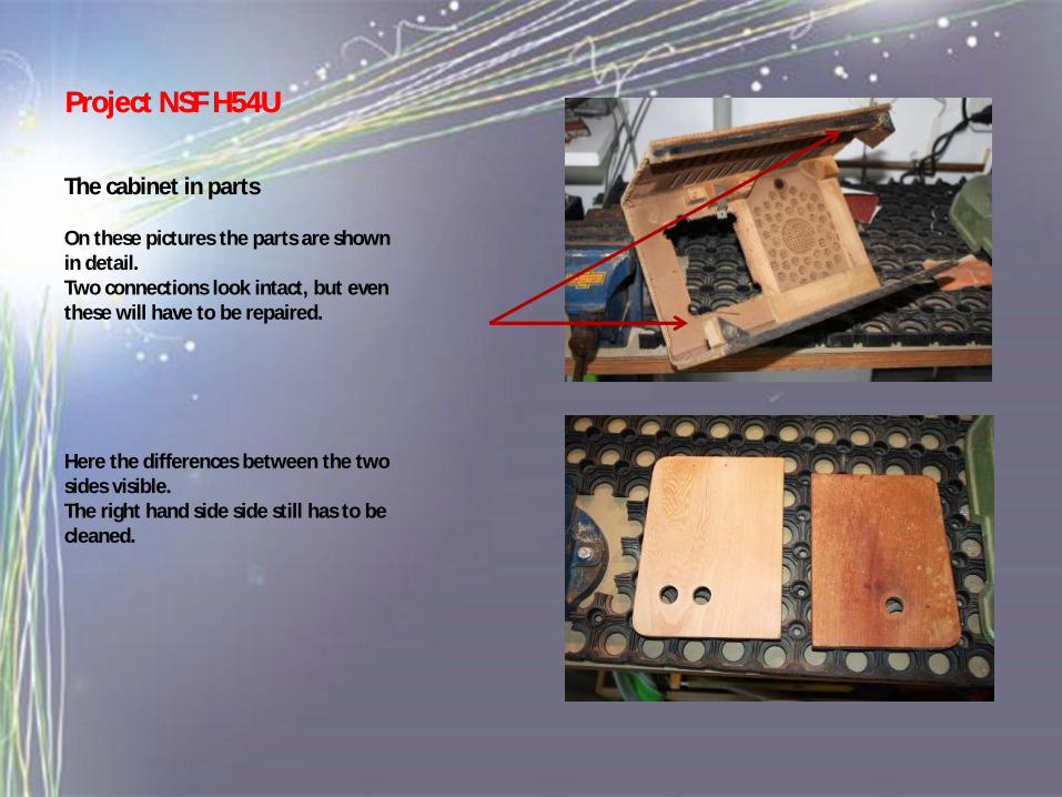
On these pictures the parts are shown in detail. Two connections look intact, but even these will have to be repaired.
Here the differences between the two sides visible. The right hand side side still has to be cleaned.
Project NSF H54UProject NSF H54U
Making new joints
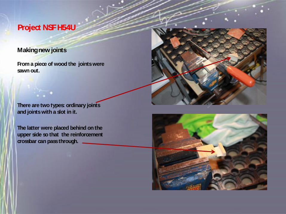
From a piece of wood the joints were sawn out.
There are two types: ordinary joints and joints with a slot in it.
The latter were placed behind on the upper side so that the reinforcement crossbar can pass through.
Project NSF H54UProject NSF H54U
Making new joints
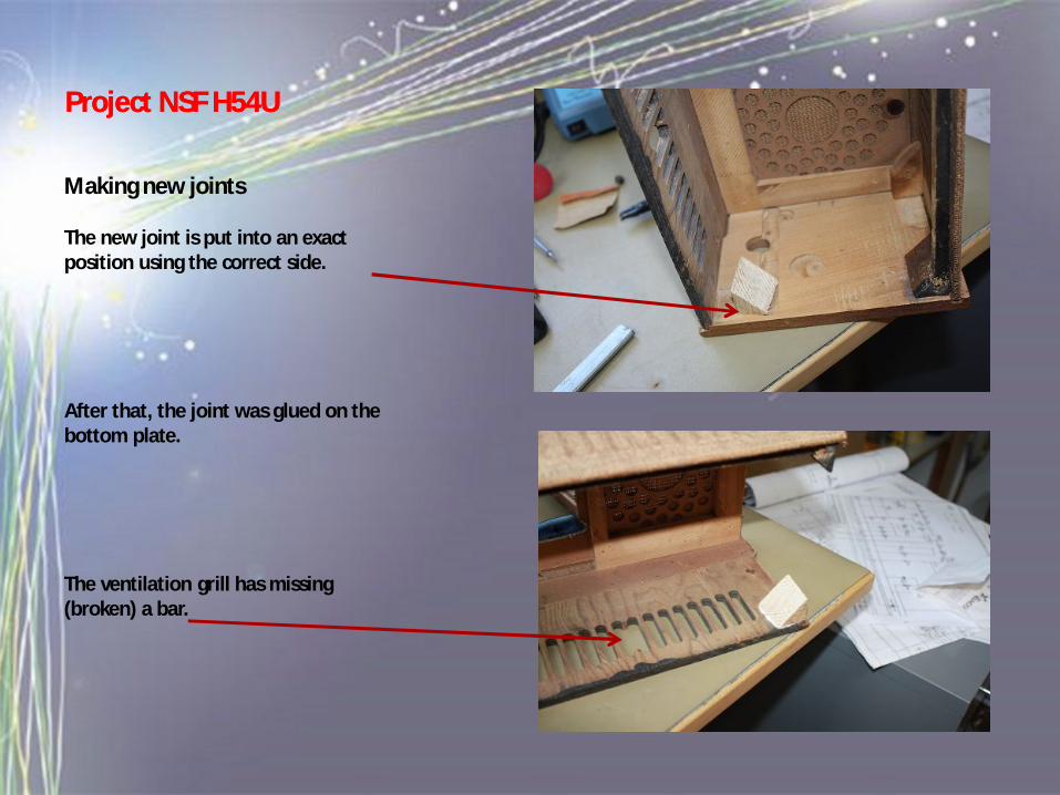
The new joint is put into an exact position using the correct side.
After that, the joint was glued on the bottom plate.
The ventilation grill has missing (broken) a bar.
Project NSF H54UProject NSF H54U
Making new joints
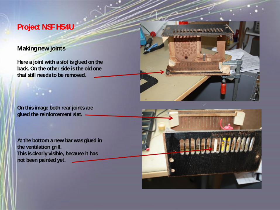
Here a joint with a slot is glued on the back. On the other side is the old one that still needs to be removed.
On this image both rear joints are glued the reinforcement slat.
At the bottom a new bar was glued in the ventilation grill. This is clearly visible, because it has not been painted yet.
Project NSF H54UProject NSF H54U
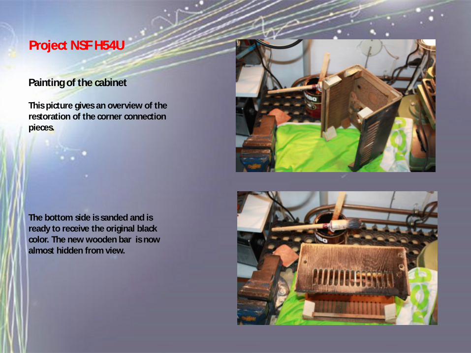
Painting of the cabinet
This picture gives an overview of the restoration of the corner connection pieces.
The bottom side is sanded and is ready to receive the original black color. The new wooden bar is now almost hidden from view.
Project NSF H54UProject NSF H54U
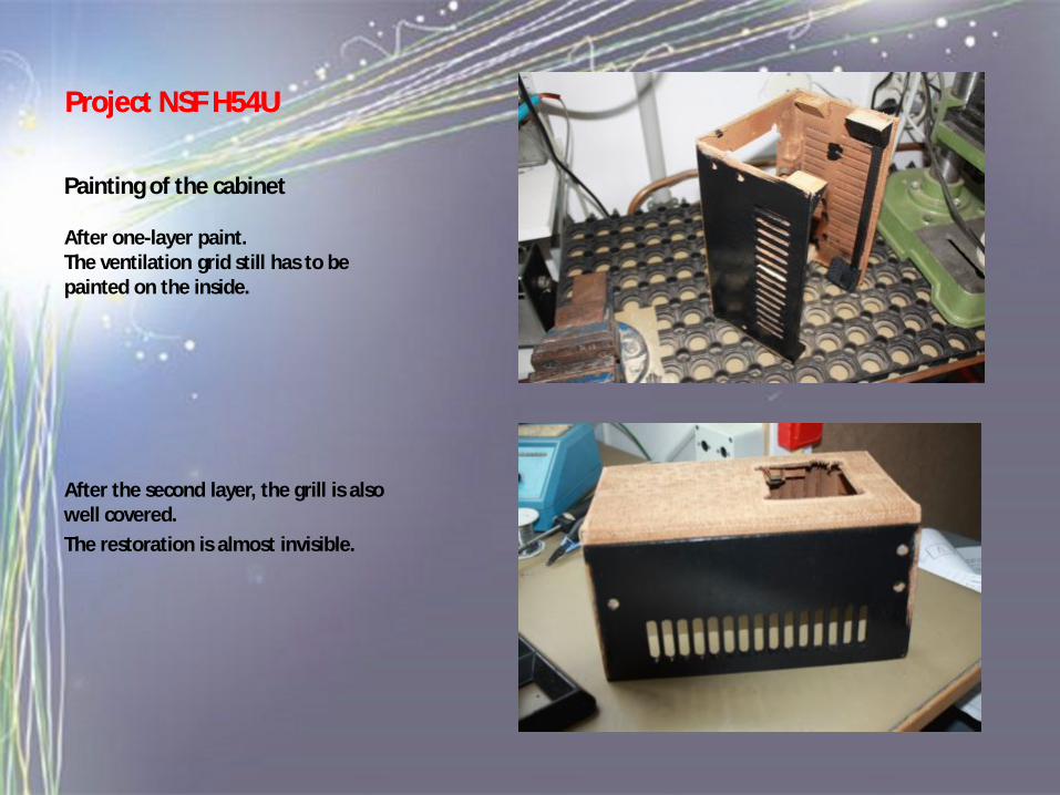
Painting of the cabinet
After one-layer paint.The ventilation grid still has to be painted on the inside.
After the second layer, the grill is also well covered. The restoration is almost invisible.
Project NSF H54UProject NSF H54U
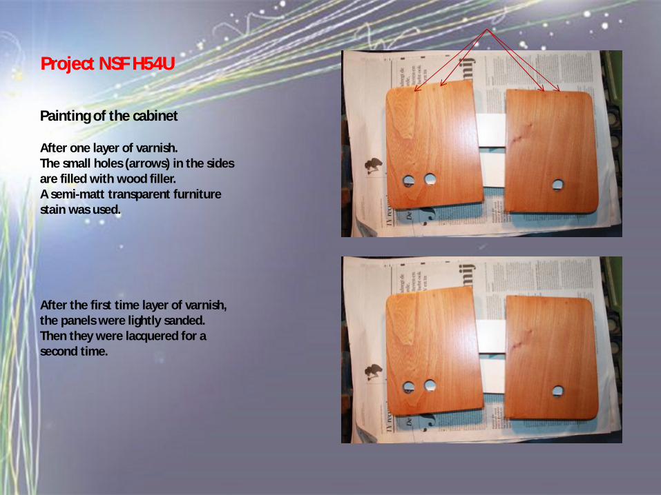
Painting of the cabinet
After one layer of varnish.The small holes (arrows) in the sides are filled with wood filler.A semi-matt transparent furniture stain was used.
After the first time layer of varnish, the panels were lightly sanded.Then they were lacquered for a second time.
Project NSF H54UProject NSF H54U
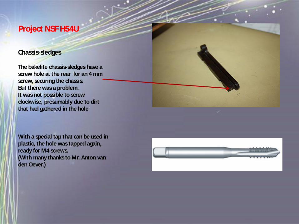
Chassis-sledges
The bakelite chassis-sledges have a screw hole at the rear for an 4 mm screw, securing the chassis.But there was a problem.It was not possible to screw clockwise, presumably due to dirt that had gathered in the hole
With a special tap that can be used in plastic, the hole was tapped again, ready for M4 screws.(With many thanks to Mr. Anton van den Oever.)
Project NSF H54UProject NSF H54U
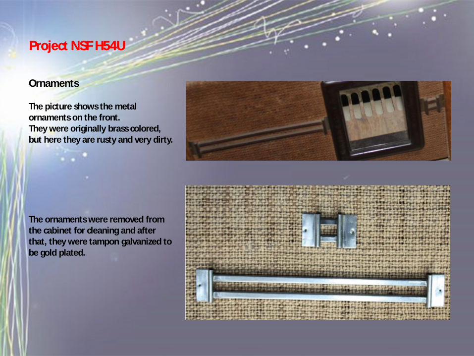
Ornaments
The picture shows the metal ornaments on the front. They were originally brass colored, but here they are rusty and very dirty.
The ornaments were removed from the cabinet for cleaning and after that, they were tampon galvanized to be gold plated.
Project NSF H54UProject NSF H54U
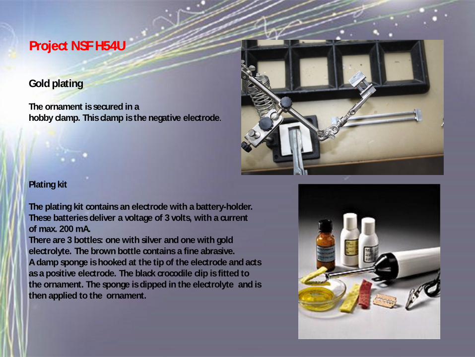
Gold plating
The ornament is secured in ahobby clamp. This clamp is the negative electrode.
Plating kit
The plating kit contains an electrode with a battery-holder. These batteries deliver a voltage of 3 volts, with a currentof max. 200 mA.There are 3 bottles: one with silver and one with gold electrolyte. The brown bottle contains a fine abrasive.A damp sponge is hooked at the tip of the electrode and acts as a positive electrode. The black crocodile clip is fitted to the ornament. The sponge is dipped in the electrolyte and is then applied to the ornament.
Project NSF H54UProject NSF H54U
Gold plating
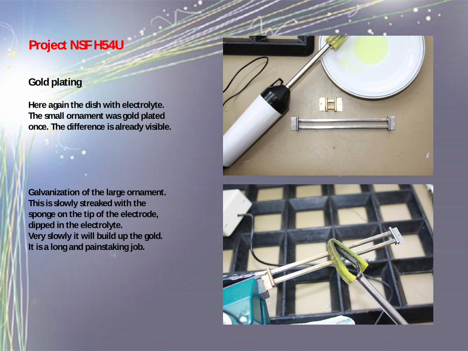
Here again the dish with electrolyte. The small ornament was gold plated once. The difference is already visible.
Galvanization of the large ornament.This is slowly streaked with the sponge on the tip of the electrode, dipped in the electrolyte.Very slowly it will build up the gold.It is a long and painstaking job.
Project NSF H54UProject NSF H54U
Gold plating
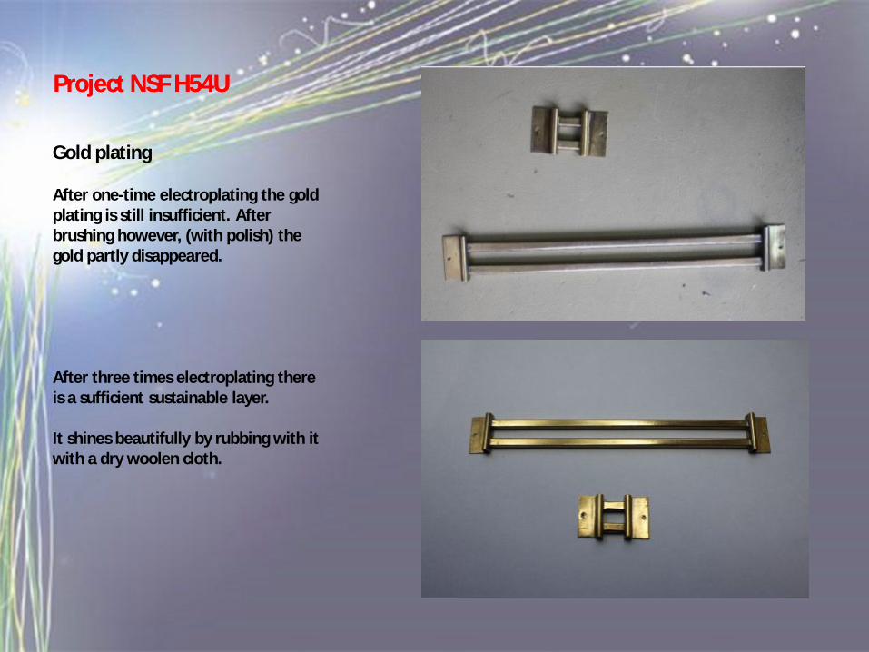
After one-time electroplating the gold plating is still insufficient. After brushing however, (with polish) the gold partly disappeared.
After three times electroplating there is a sufficient sustainable layer.
It shines beautifully by rubbing with it with a dry woolen cloth.
Project NSF H54UProject NSF H54U
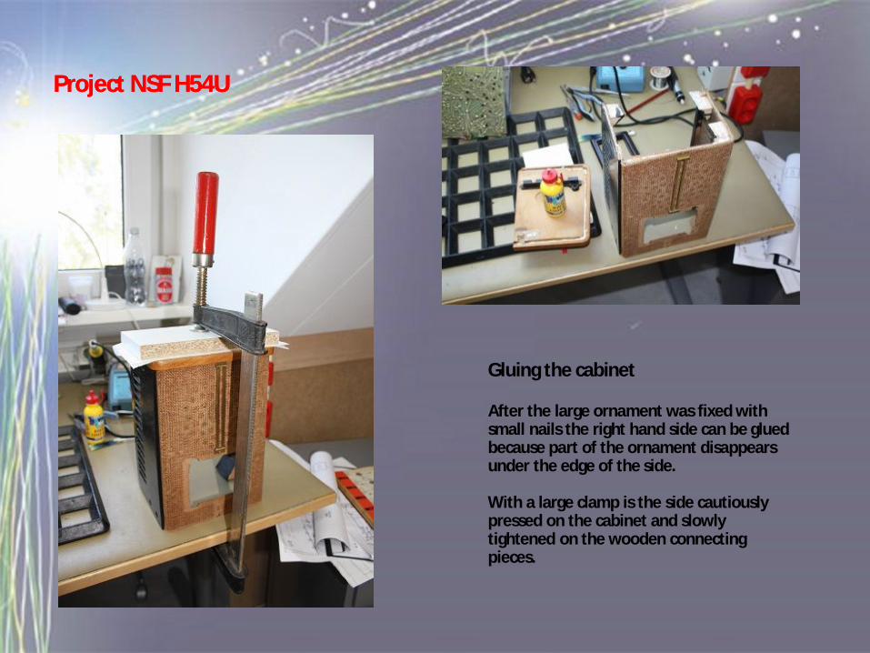
Gluing the cabinet
After the large ornament was fixed with small nails the right hand side can be glued because part of the ornament disappears under the edge of the side.
With a large clamp is the side cautiously pressed on the cabinet and slowly tightened on the wooden connecting pieces.
Project NSF H54UProject NSF H54U
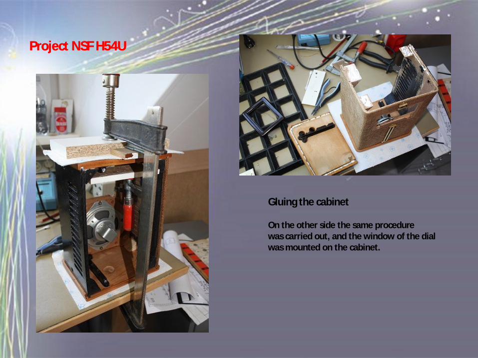
Gluing the cabinet
On the other side the same procedure was carried out, and the window of the dial was mounted on the cabinet.
Project NSF H54UProject NSF H54U
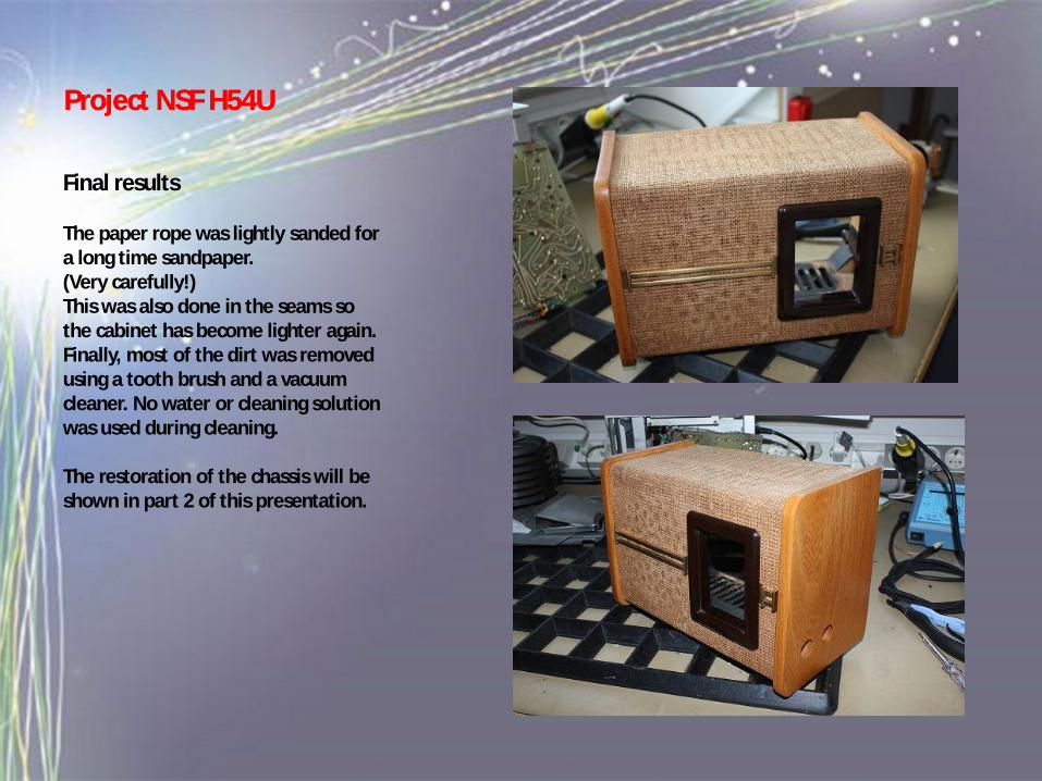
Final results
The paper rope was lightly sanded for a long time sandpaper.(Very carefully!)This was also done in the seams so the cabinet has become lighter again.Finally, most of the dirt was removed using a tooth brush and a vacuum cleaner. No water or cleaning solution was used during cleaning.
The restoration of the chassis will be shown in part 2 of this presentation.
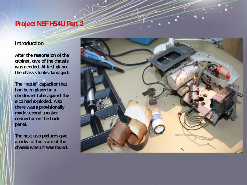
Introduction
After the restoration of the cabinet, care of the chassis was needed. At first glance, the chassis looks damaged.
The “rattle” capacitor that had been placed in a deodorant tube against the elco had exploded. Also there was a provisionally made second speaker connector on the back panel.
The next two pictures give an idea of the state of the chassis when it was found.
Project NSF H54U Part 2Project NSF H54U Part 2
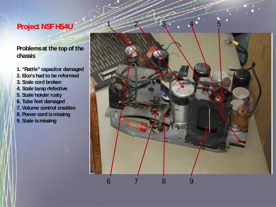
Problems at the top of the chassis
1. “Rattle” capacitor damaged2. Elco's had to be reformed3. Scale cord broken4. Scale lamp defective5. Scale holder rusty6. Tube feet damaged7. Volume control crackles8. Power cord is missing9. Scale is missing
1 2 3 4 5
6 7 8 9
Project NSF H54UProject NSF H54U
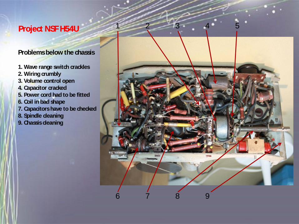
Problems below the chassis
1. Wave range switch crackles2. Wiring crumbly3. Volume control open4. Capacitor cracked5. Power cord had to be fitted6. Coil in bad shape7. Capacitors have to be checked8. Spindle cleaning9. Chassis cleaning
1 2 3 4 5
6 7 8 9
Project NSF H54UProject NSF H54U
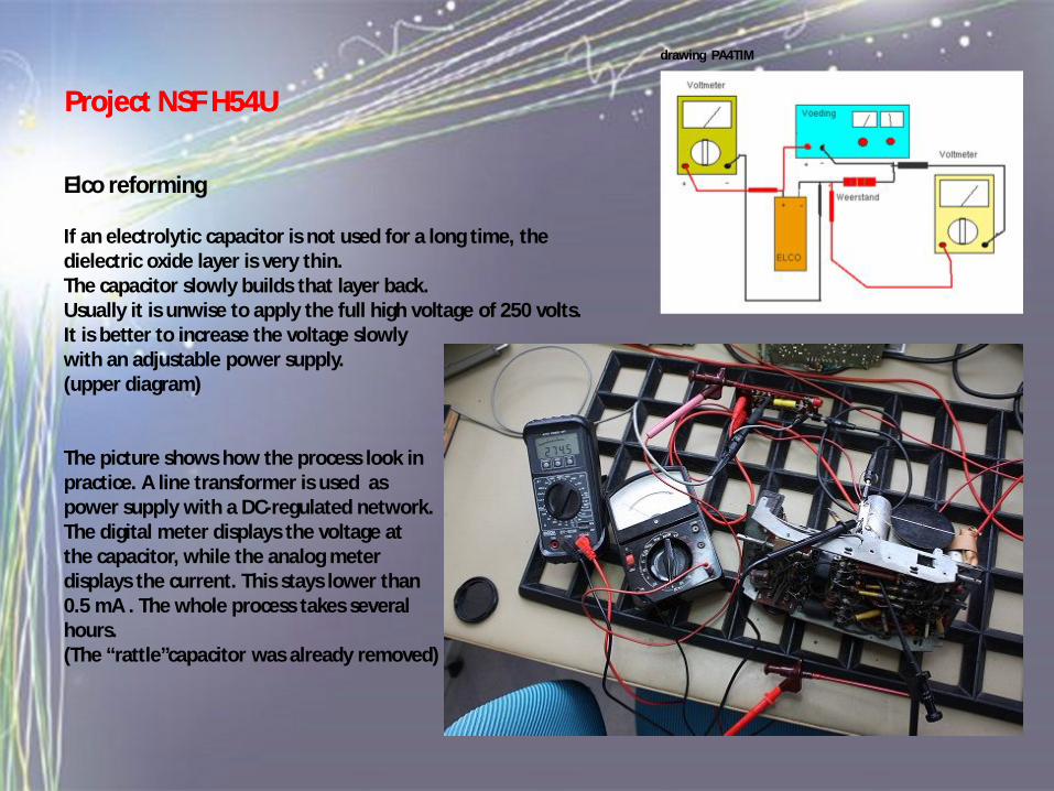
Elco reforming
If an electrolytic capacitor is not used for a long time, the dielectric oxide layer is very thin.The capacitor slowly builds that layer back.Usually it is unwise to apply the full high voltage of 250 volts.It is better to increase the voltage slowlywith an adjustable power supply.(upper diagram)
The picture shows how the process look inpractice. A line transformer is used aspower supply with a DC-regulated network.The digital meter displays the voltage atthe capacitor, while the analog meterdisplays the current. This stays lower than0.5 mA . The whole process takes severalhours.(The “rattle”capacitor was already removed)
drawing PA4TIM
Project NSF H54UProject NSF H54U
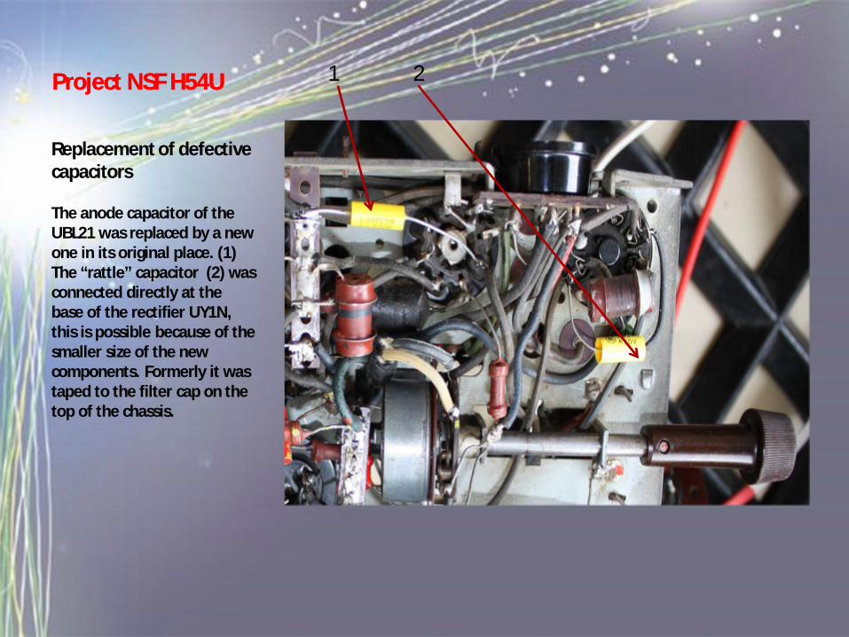
Replacement of defective capacitors
The anode capacitor of the UBL21 was replaced by a new one in its original place. (1)The “rattle” capacitor (2) was connected directly at the base of the rectifier UY1N, this is possible because of the smaller size of the new components. Formerly it was taped to the filter cap on the top of the chassis.
1 2Project NSF H54UProject NSF H54U
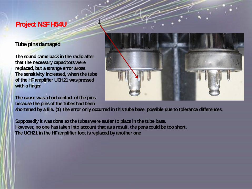
Tube pins damaged
The sound came back in the radio afterthat the necessary capacitors were replaced, but a strange error arose. The sensitivity increased, when the tubeof the HF amplifier UCH21 was pressedwith a finger.
The cause was a bad contact of the pinsbecause the pins of the tubes had been shortened by a file. (1) The error only occurred in this tube base, possible due to tolerance differences.
Supposedly it was done so the tubes were easier to place in the tube base.However, no one has taken into account that as a result, the pens could be too short. The UCH21 in the HF amplifier foot is replaced by another one
1Project NSF H54UProject NSF H54U
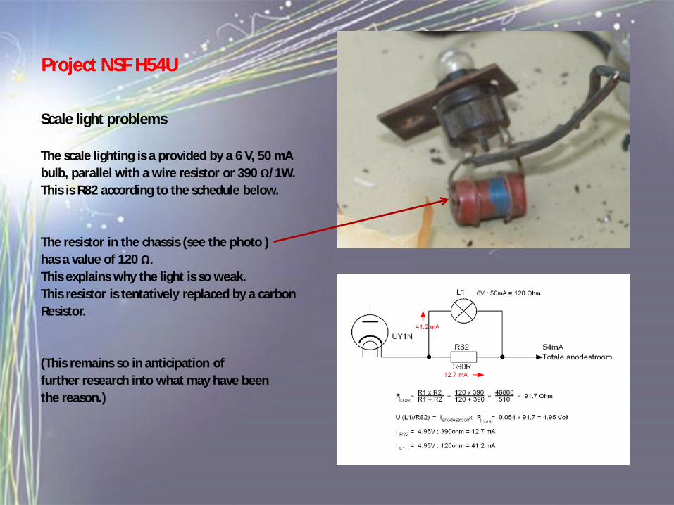
Scale light problems
The scale lighting is a provided by a 6 V, 50 mAbulb, parallel with a wire resistor or 390 Ω/1W. This is R82 according to the schedule below.
The resistor in the chassis (see the photo )has a value of 120 Ω.This explains why the light is so weak.This resistor is tentatively replaced by a carbonResistor.
(This remains so in anticipation offurther research into what may have beenthe reason.)
Ed van der Weele
Project NSF H54UProject NSF H54U

Scale repair cord 12
The entire scale cord has a length of 3ca. 30 cm. In order to be able to workwith it, a length of 45 cm is sufficient.
The cord is turned 3 x around the axis (1)so that the dial moves in the right direction.The cord was secured on one side (2) to thespring and tensioned.
A clamp holds the cord fixed between theedge of the chord wheel. (3)Now the other end of the cord is tied to the spring (4)
The cord was wound on the wheel .After that the clamp was removed and the 4wheel was mounted on the axis of the tuningcapacitor.
Project NSF H54UProject NSF H54U
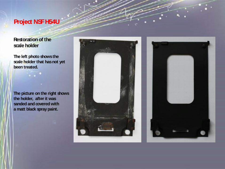
Restoration of the scale holder
The left photo shows thescale holder that has not yetbeen treated.
The picture on the right showsthe holder, after it was sanded and covered witha matt black spray paint.
Project NSF H54UProject NSF H54U
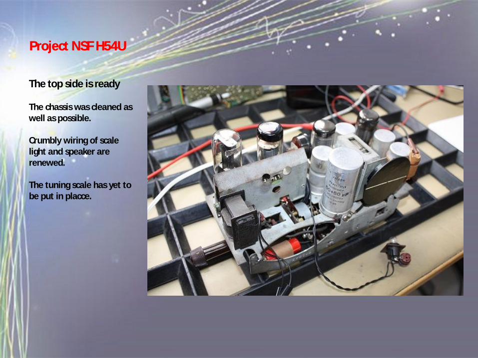
The top side is ready
The chassis was cleaned as well as possible.
Crumbly wiring of scale light and speaker are renewed.
The tuning scale has yet to be put in placce.
Project NSF H54UProject NSF H54U
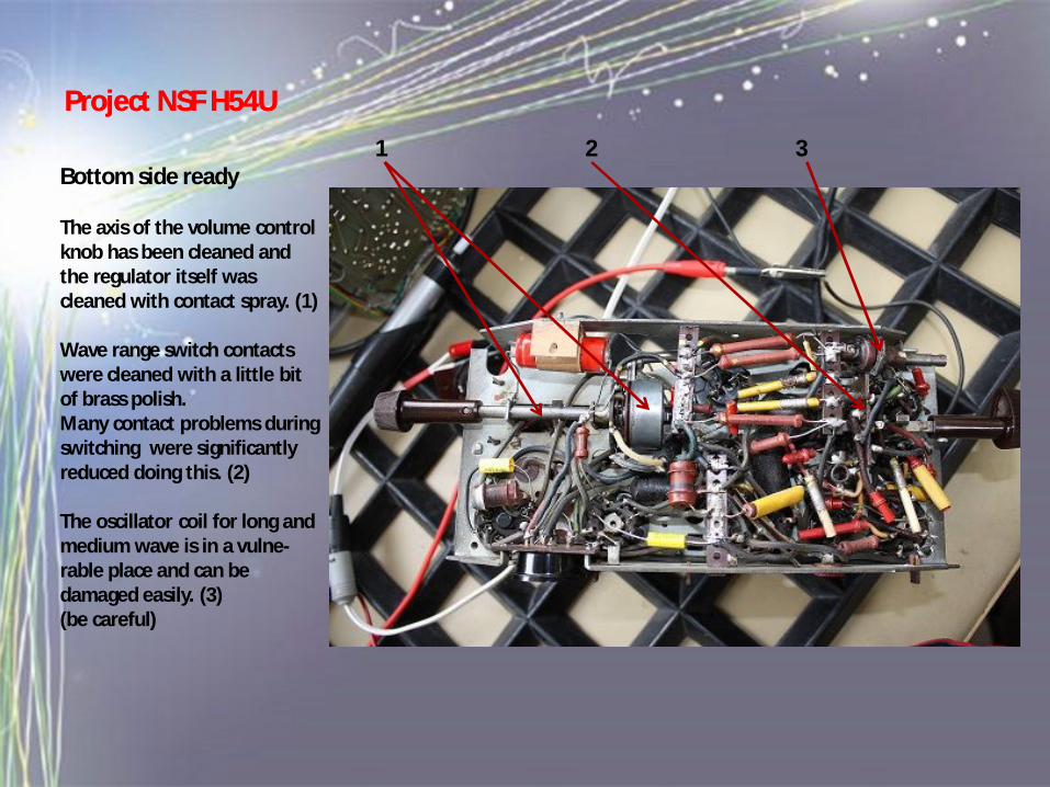
1 2 3Bottom side ready
The axis of the volume controlknob has been cleaned andthe regulator itself wascleaned with contact spray. (1)
Wave range switch contactswere cleaned with a little bitof brass polish.Many contact problems duringswitching were significantlyreduced doing this. (2)
The oscillator coil for long andmedium wave is in a vulne-rable place and can bedamaged easily. (3)(be careful)
Project NSF H54UProject NSF H54U
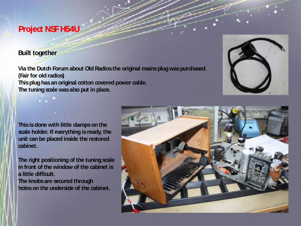
Built together
Via the Dutch Forum about Old Radios the original mains plug was purchased.(Fair for old radios)This plug has an original cotton covered power cable.The tuning scale was also put in place.
This is done with little clamps on thescale holder. If everything is ready, theunit can be placed inside the restored cabinet.
The right positioning of the tuning scalein front of the window of the cabinet isa little difficult. The knobs are secured throughholes on the underside of the cabinet.
Project NSF H54UProject NSF H54U
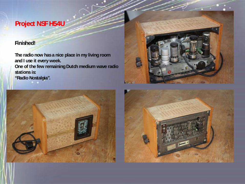
Finished!
The radio now has a nice place in my living roomand I use it every week.One of the few remaining Dutch medium wave radio stations is:“Radio Nostalgia”.
Project NSF H54UProject NSF H54U
Project NSF H54UProject NSF H54U
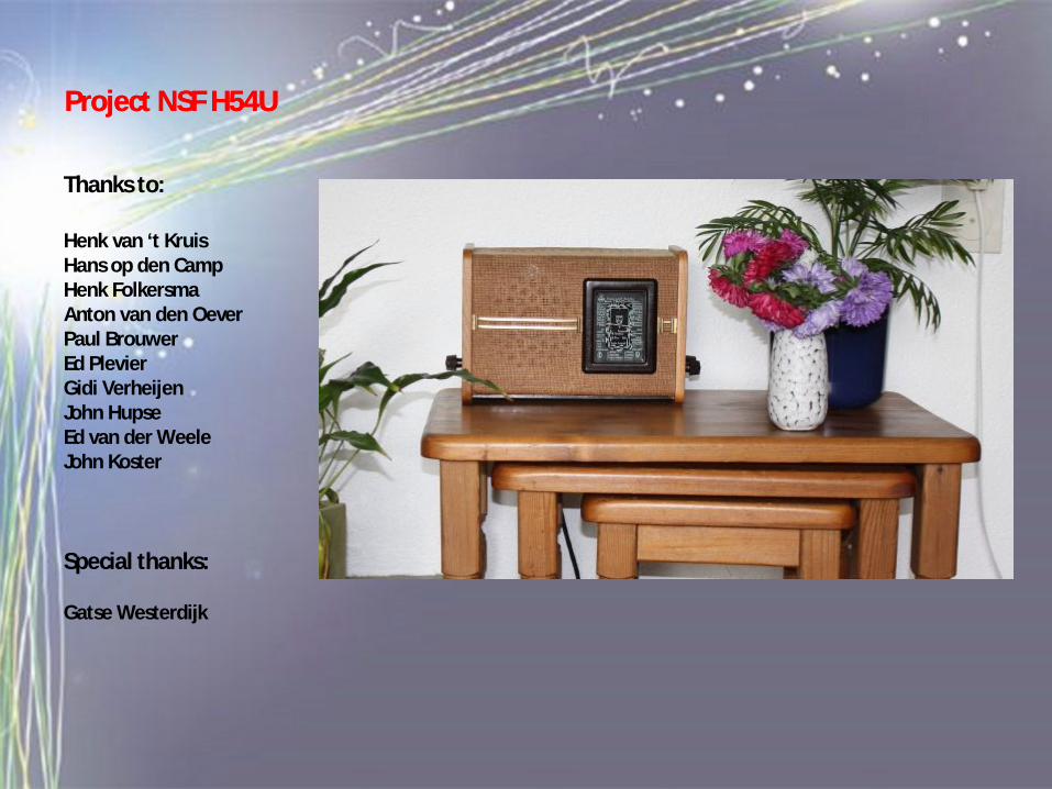
Thanks to:
Henk van ‘t KruisHans op den CampHenk FolkersmaAnton van den OeverPaul BrouwerEd PlevierGidi VerheijenJohn HupseEd van der WeeleJohn Koster
Special thanks:
Gatse Westerdijk