Embed Size (px)
Citation preview

Table of Contents Page 1 JSE Project 1409
PROJECT MANUAL TABLE OF CONTENTS NETWORK UPGRADES AT M. O. CAMPBELL EDUCATION CENTER ENGINEER’S PROJECT 1409
SPECIFICATIONS
SECTION 15050 GENERAL MECHANICAL 8 PAGES SECTION 15200 MECHANICAL INSULATION 2 PAGES SECTION 15650 MECHANICAL EQUIPMENT 6 PAGES SECTION 15800 AIR DISTRIBUTION 6 PAGES SECTION 16050 GENERAL ELECTRICAL 8 PAGES SECTION 16420 ELECTRICAL EQUIPMENT 7 PAGES SECTION 16450 ELECTRICAL WIRING 8 PAGES
DRAWING LIST
MEP1.0 M. O. CAMPBELL MEP OVERALL FLOOR PLANS MEP1.1 M. O. CAMPBELL MEP FLOOR PLANS M2.0 M. O. CAMPBELL MECHANICAL SCHEDULES AND DETAILS E2.0 M. O. CAMPBELL ELECTRICAL SCHEMATIC E2.1 M. O. CAMPBELL ELECTRICAL SCHEDULES AND DETAILS
03/31/2014

15050 - General Mechanical Page 1 Project 1409
SECTION 15050 - GENERAL MECHANICAL 1.01 RELATED DOCUMENTS` The General Provisions of the Contract, including General, Supplementary and Special
Conditions, apply to the work specified in this Section. 1.02 INTENT OF DRAWINGS AND SPECIFICATIONS
A. Drawings and Specifications are intended to be complimentary. Any work exhibited in either of them whether in the other or not, is to be executed according to true intent and meaning thereof, the same as if set forth in all. Should any work required by the drawings and specifications be in violation of any Federal, State, County or City laws, ordinance or regulation, those laws and regulations shall prevail, and shall be complied with by the Contractor as a part of this work with no extra compensation.
B. The drawings are schematic in nature, but show the various components of the system
approximately to scale and indicate how they are to be integrated with other parts of the building. Determine exact locations by close coordination with the Owner’s Representative, job measurements, determining the requirements of other trades and reviewing all contract documents. The Drawings indicated general routing of the various parts of the systems, but do not indicated all fittings, offsets and runouts which are required. The Contract includes these items as required to fit the system into spaces allotted for them.
C. Equipment that is scheduled is the basis of the design, and have been coordinated for space,
installation and electrical requirements. Space, installation and electrical requirements for other equipment and models from acceptable manufacturers have not been verified or coordinated. Contractor shall verify these requirements prior to using other equipment in his bid and include any additional costs for installation of the equipment. This includes general construction and MEP costs.
1.03 PERMITS AND FEES The contractor shall obtain and pay for all permits and licenses, file all notices, pay all legal fees
and comply with all laws, ordinances, rules and regulations bearing on the conduct of the work specified or shown on the drawings. This applies to Federal, State and Local Codes and Requirements. Approval to the various insuring and inspection authorities shall also be obtained. Refer to Architectural sections for additional information.
1.04 GUARANTEE
All materials, apparatus and equipment furnished and installed under this Section of these Specifications shall be new and free from any defects when accepted by the Owner and shall be guaranteed in writing for a period of one year from the date of acceptance by the Owner unless noted to have extended warranties.

15050 - General Mechanical Page 2 Project 1409
1.05 COOPERATION The Contractor shall cooperate with other trades on the job and make installations in the proper sequence during the construction of the buildings, and he shall notify the Architect well in advance of construction of all interference of his work with that of other trades and of building construction. This notification shall not relieve the contractor of his responsibilities.
1.06 VISITING THE SITE The Contractor shall be familiar with the Drawings and Specifications and shall have examined
the premises and understand the conditions under which he will be obligated to operate in performing the contract. No allowance shall be made consequently for any error through negligence in this regard.
1.07 WORKMANSHIP
All work shall be performed in a neat workmanlike manner and in the best practice of the trade. Only workmen skilled in the trades shall be employed to perform the work included in these specifications.
1.08 MATERIALS
A. Materials, when not otherwise definitely specified, shall conform to applicable National Specifications and Standards. All materials shall be certified to not contain any asbestos or other material banned by the Environmental Protection Agency. Lead shall not be used in any material, pipe or solder in contact with the domestic water system.
B. The names of manufacturers and model numbers have been used in the Contract Documents to
establish type of equipment and standard of quality. Where only one name is mentioned for a particular item of material, then that manufacturer is the only one acceptable. Where several names are mentioned, any one of those listed may be furnished provided submittal contains sufficient information to show complete compliance with contract Documents. No attempt has been made to determine if each manufacturer listed will produce material that will comply with all requirements of this project or will fit the allotted space; if they do, then it will be acceptable.
C. Requests for substitution during the bidding period, in accordance with the requirements of the
Special Conditions, must be accompanied by a complete product submittal with all features, accessories and capacities noted. Large equipment must include a 1/4" scale drawing showing how the equipment and required access space are compatible with the available space. Acceptance for bidding does not waive the post bidding requirement for formal submittal and approval.
1.09 REMOVAL OF RUBBISH AND CLEAN-UP Keep area of operations free from accumulation of waste material or rubbish at all times. At the
completion of the work, remove all rubbish, tools, scaffolding and surplus materials from the area of operations. The exposed parts of the Mechanical installation which are to be painted shall be thoroughly cleaned of cement, plaster, grease, oil spots and other materials in preparation for painting. All piping shall be cleaned of cement, plaster and other construction debris prior to being concealed above accessible ceilings or being insulated. Clean exposed piping prior to final inspection. All construction areas shall be left "broom" clean on a daily basis. Prior to final acceptance, vacuum clean all mechanical rooms including equipment.

15050 - General Mechanical Page 3 Project 1409
1.10 OPERATION TESTS AND ADJUSTMENTS After completion of the work and before final acceptance thereof, the Contractor shall notify the
Architect when he is ready for the balancing of air and hydronic systems which will be performed by a professional test and balance firm selected by the Owner as described in Section 15960.
1.11 LUBRICATION
After the installation is completed, lubricate all moving parts of all equipment furnished under this Division of the Specifications requiring same. Leave with the Owner a brief but complete set of lubrication instructions, showing the recommended frequency of lubrication and the type of lubricant recommended for each piece of equipment.
1.12 NOISE AND VIBRATIONS The Contractor shall guarantee that the entire system and its component items of equipment, as
installed by him, shall operate without objectionable vibration or noises, as determined by the Architect. If, in the opinion of the Architect, objectionable vibration or transmission thereof to the building occurs, the Contractor shall execute such remedial measures as are necessary to eliminate such unsatisfactory operating conditions and the material and labor thereby required shall be performed at the Contractor's expense.
1.13 RELATED WORK SPECIFIED IN OTHER SECTIONS
A. ELECTRICAL: Power wiring is specified in the Electrical Section. Interlock and control wiring (any voltage) is specified under this Section. Controllers and starters, unless part of a motor control center, are specified under this Section.
B. PAINTING OF EQUIPMENT, PIPING AND ACCESSORIES: Painting Section. However, all
items furnished under this Section shall be kept clean and free from corrosion. C. OPENINGS: Various Sections. However, the locations of all inserts and openings shall be
determined under this Section and coordinated with other Sections in ample time to avoid cutting new construction.
D. CUTTING, PATCHING AND FURRING: Various Sections. However, the locations of all inserts
and openings shall be determined and coordinated with other sections. E. EQUIPMENT AND PIPING SUPPORTS: Refer to structural drawings, details and notes for
specific support and pipe hanging requirements. Specific loading and attachment methods shall be followed to assure that individual structural members are not overloaded.
1.14 GENERAL EQUIPMENT REQUIREMENTS Manufacturer's printed directions shall be followed for preparing, assembling, installing, erecting
and cleaning manufactured materials or equipment, unless otherwise directed.

15050 - General Mechanical Page 4 Project 1409
1.15 SHOP DRAWINGS
A. Submit seven complete sets of shop drawings checked and certified by the contractor as being checked, and lists of materials furnished under this Division. Shop drawings shall be approved before installation of the material under consideration.
B. Shop Drawings shall consist of published ratings of capacity data, detailed construction drawings,
wiring and control diagrams, performance curves, installation instructions, manufacturer's installation drawings and other pertinent data. Where the literature is submitted covering a group or series of similar items, the item under consideration shall be clearly indicated. Ductwork shop drawings shall include one blueline set and one reproducible set. Drawings shall be submitted showing revisions to equipment layouts due to use of alternate or substitute equipment. The front sheet of each copy of the submittal shall have the following typed information:
1. Job name and location. 2. General Contractor's name, address, Project Manager's name and telephone number. 3. Submitting Sub-contractor's name, address, Project Manager's name and telephone
number. 4. Suppliers company name, address, salesman's name and telephone number. 5. Signature of an officer or attorney-in-fact of the Sub-contractor with date and title and a
statement that the submittal materials and equipment complies with the Contract Documents.
Any submittal without all of the above information will be rejected without review. C. Shop Drawings are required for but are not limited to the following items:
Air Handling Units VAV Boxes Plumbing Carriers, Drains & Cleanouts Chillers Boilers Grease Trap & Sampling Wells Pumps Water Specialties Plumbing Fixtures & Equipment Insulation Air Devices Plumbing Pipe, Valves & Fittings Motor Starters Ductwork Trap Priming Manifolds Fans & Roof Curbs Controls Water Heaters Rooftop Units Fire & Smoke Dampers Gas Pressure Regulators Vibration Isolation Electric Duct Heaters Shower Mixing Valves Sound Attenuators Roof Pipe Supports Pipe Markers 1/2" Scale Drawings of Main Mechanical Room Fire Sprinkler System incl calculations Chilled Water Piping in All Mechanical Rooms Split System
D. Approval of these submittals shall not be construed as releasing the contractor from compliance
with the contract Documents. They are a means of coordinating the work and aiding in the proper selection and installation of equipment. Do not release items such as fire dampers and starters until associated equipment or ductwork drawings are approved. All materials and equipment shall be subject to final acceptance by the Engineer at the completion of construction and adjustments of the system.
E. If a submittal is returned to the Contractor marked “Rejected” or “Revise and Resubmit”, only one
(1) additional submittal will be permitted without the Contractor incurring charges for the additional re-submittals. JSE shall be reimbursed by the Contractor for any expense in connection with any necessary submission in addition to the two (2) submissions allowed. Contractor will be billed by JSE at a rate of $125/hr for these occurrences.

15050 - General Mechanical Page 5 Project 1409
1.16 PROTECTION OF EQUIPMENT
A. Do not deliver equipment to jobsite until progress of construction has reached the stage where equipment is actually needed, or until building is closed in enough to protect equipment from the weather. Equipment allowed to stand in weather will be rejected, and Contractor is obligated to furnish new equipment at no cost to Owner.
B. Adequately protect equipment (including all Owner-furnished items) from damage after delivery to
job. Cover with heavy cloth as required to protect from damage. C. Equipment which has been damaged by construction activities will be rejected. Contractor shall
furnish new equipment at no cost to Owner.
1.17 CUTTING AND PATCHING Coordinate the work with other trades to arrange for all holes, chases, and other spaces
necessary for the installation of all components of the mechanical systems. Inform the other trades in ample time for these to be provided. Failure to comply with this requirement may necessitate cutting and patching work. If such work becomes necessary, it will be done under this Section of the specifications, and shall conform to all applicable requirements of other Sections of the Specifications.
1.18 STRUCTURAL STEEL All structural steel used for the purpose of fabricating pipe supports, pipe guides, pipe anchors,
equipment supports, and framing for large ducts and plenums, shall conform to ASTM Designation A-36. All steel used for these purposes shall be new, clean, straight and galvanized.
1.19 SPARE PARTS LISTS, OPERATING INSTRUCTIONS At completion of job, furnish three copies of spare parts lists and operating instructions for all
equipment furnished under this Division. These lists and instructions shall be published by the manufacturer of the equipment and shall be in good condition. Bind in 3-ring binder with project name.
1.20 TOOLS AND SPARE PARTS Upon completion of the installation, deliver to the Owner all tools and spare parts that are
furnished by the Equipment Manufacturer for use with the equipment furnished under this Contract.
1.21 REFRIGERANT AND OIL Furnish and install full refrigerant and oil charge in the air conditioning refrigeration systems and
maintain it for full term of the guarantee.

15050 - General Mechanical Page 6 Project 1409
1.22 RECORD DRAWINGS
Obtain a set of project drawings and keep these at jobsite during construction. During the course of construction, mark on these prints any changes which are made, noting particularly locations for those items which will need to be located for servicing. At completion of job, mark each sheet "Record Drawings", date and deliver to Architect.
1.23 OWNER'S INSTRUCTIONS Provide the following periods of instruction to the Owner's designated personnel upon completion
of the system's installation: HVAC System - 8 Hours Temperature Controls Systems - 8 Hours Plumbing Systems - 4 Hours
1.24 MEP INSPECTIONS
A. Contractor shall formally request inspections from JSE to review any and all MEP installations.
Inspections shall include but not be limited to: pipe tests, underground installations prior to backfill, rough-in installations, wall cover inspections, above ceiling inspections, final inspection.
B. Information required from Contractor on each and every request for inspection is as follows:
1. Specific type of test (i.e. hydrostatic test, head pressure test, medium pressure duct test,
etc.). 2. Exact location of test (i.e. area of building with wing or room numbers). 3. Description of test (i.e. partial inspection, walls only, chase walls, wall cover, ceiling cover,
etc.) 4. Exact time test started (required test time per Project Manual will need to have elapsed prior
to JSE inspection). Estimated time test will start will not be acceptable. 5. Pressure reading on gauge at time of request for all pipe tests (provide picture of gauge with
request). 6. Verification from General Contractor with name of person that verified, that specific test has
been verified by the Contractor and all sub-contractors to meet all requirements of the Specifications and Codes (prior to inspection request).
C. Contractor shall provide a MINIMUM of 48 hour notice prior to requested inspection time, no
exceptions.

15050 - General Mechanical Page 7 Project 1409
D. INSPECTION REPORTS: After each inspection, JSE will generate an inspection report and distribute promptly. The Contractor will then be given 7 working days from date of report to address all deficiencies listed on the report. The GENERAL CONTRACTOR shall verify that all items on each inspection report have been addressed by their subcontractors in this time period. Once verified the GENERAL CONTRACTOR shall sign-off on each deficiency listed on the report and return the signed-off copy of the inspection report to JSE via e-mail. After the signed-off report is returned to JSE, the GENERAL CONTRACTOR shall request a re-inspection by JSE to close the report. If after 7 working days no re-inspection is requested by the GENERAL CONTRACTOR to close a report, JSE reserves the right to re-inspect whenever our schedule allows, with these re-inspections still being subject to Paragraph E below.
E. TEST REJECTIONS AND RE-INSPECTIONS: If a test is rejected or a re-inspection of an issued
JSE Inspection Report is found to NOT be completely addressed, only ONE (1) additional inspection will be permitted without the Contractor incurring charges for each additional inspection required. JSE shall be reimbursed $500 by the GENERAL CONTRACTOR for expenses in connection with EACH inspection in addition to the two (2) inspections allowed.
1.25 SUBSTITUTIONS A. The names of manufacturer and model numbers have been used in the Contract Documents to
establish types of equipment and standards of quality and are intended to be the Basis of Bid. If only one manufacturer is named for a specific item of equipment alternate manufacturers shall be acceptable as a substitution/approved equal as specified in this Article.
B. All other brands, including any additional names which may be listed as “Alternates” or “Approved
Equal” must conform with the specifications, size, accessories, etc. of the first named brand and be subject to Paragraph D and E of this Article. Alternate equipment must be equal from the standpoint of materials, construction and performance. Request for substitution must be accompanied by complete data and descriptive sheets during the bidding period as described in Paragraph D and E of this Article.
1. Submited on Bidder’s letterhead attached to Proposal Form with individual deductive
amounts stipulated and the documentation required in Paragraph E-03. 2. All savings for Owners selection of deductive amounts by acceptance of alternate or
substituted items are to be paid to the Owner. C. All equipment within common group or category (e.g. air devices, HVAC terminal units, floor
drains/clean outs, fire sprinkler devices, etc.) shall be same manufacturer. D. Proposed Substitutions/Approved Equals:
1. Submitted no less than 7 calendar days prior to bid date. 2. Submit proposed substitutions with catalog data and/or manufacturer’s shop details
indicating all modifications required to conform with specified brand. Include all relevant items necessary to make a determination of equal status or submittal shall be deemed incomplete and rejected.
3. If submittal contains sufficient information to prove compliance with the Contract Documents, then that alternate submittal will be acceptable. Approved submittals for bidding purposes only will be published by addenda.
E. Substitutions with prior approval:
1. Submitted on Bidder’s letterhead attached to Proposal Form with individual additive/deductive amounts stipulated and the documentation required in Paragraph B-2.

15050 - General Mechanical Page 8 Project 1409
2. Owner reserves the right to accept or reject any or all substitution proposals before execution of Contract.
3. Provide all design/engineering services required to make adjustments in space, systems, utilities, etc. and pay all additional costs of utilities, construction or professional services that may be incurred due to the acceptance of any substitution.
END OF SECTION

15200 - Mechanical Insulation Page 1 Project 1409
SECTION 15200 - MECHANICAL INSULATION PART 1 - GENERAL 1.01 RELATED DOCUMENTS The General Provisions of the Contract, including General, Supplementary and Special
Conditions, apply to the work specified in this Section. 1.02 GENERAL REQUIREMENTS
A. Install all insulation in conformance with manufacturer's recommendations and these specifications.
B. Insulation materials manufactured by the following list of companies will be acceptable provided
their materials conform to these specifications (see Paragraph on Substitution): Armstrong, CertainTeed, Childers, Foster, Knauf, Koolphen, Manville, Owens-Corning, Pabco, Pittsburg-Corning and SPI.
C. Flame Spread and Smoke Requirements:
1. All jackets, adhesives, coatings, insulating materials and vapor barrier mastics for air distribution systems shall meet the requirements of NFPA Bulletin 90-A with a flame spread of 25 or less and smoke developed rating not higher than 50.
2. All jackets, adhesives, coatings, insulating materials and vapor barrier mastics for piping and
equipment shall have a flame spread not higher than 25 and smoke developed rating not higher than 50.
3. All materials containers shall have a U. L. Label.
D. At each pipe support point, install a hard section of Koolphen K phenolic foam pipe insulation, minimum 18" length, on lower 180° of piping, 360° if clamps are used on top of pipe, same thickness as adjacent insulation, to prevent compression at support bearing area. Seal and finish to match adjoining insulation. Provide formed 16 gage galvanized sheetmetal saddles, same length as hard section, to completely cover hard section.
E. Install .020" thick aluminum jacket with minimum 2” overlap joint on all insulated piping exposed
outside building. Install factory made aluminum covers on all elbows. Cut aluminum neatly to fit all tees, such that all insulation is covered by aluminum. Use waterproofing aluminum colored Foster 95-44 sealer to seal all joints. Provide .020x3/4” aluminum bands not more than 12" on center for all jacketing. Install aluminum covers on insulated pipe inside that is exposed to view in finished areas. Cover is not required in mechanical or AHU rooms. Jacketing in contact with soil shall be .010" stainless steel.
PART 2 - MATERIALS AND METHODS 2.01 CONDENSATE DRAINS
15200 - Mechanical Insulation Page 2 Project 1409
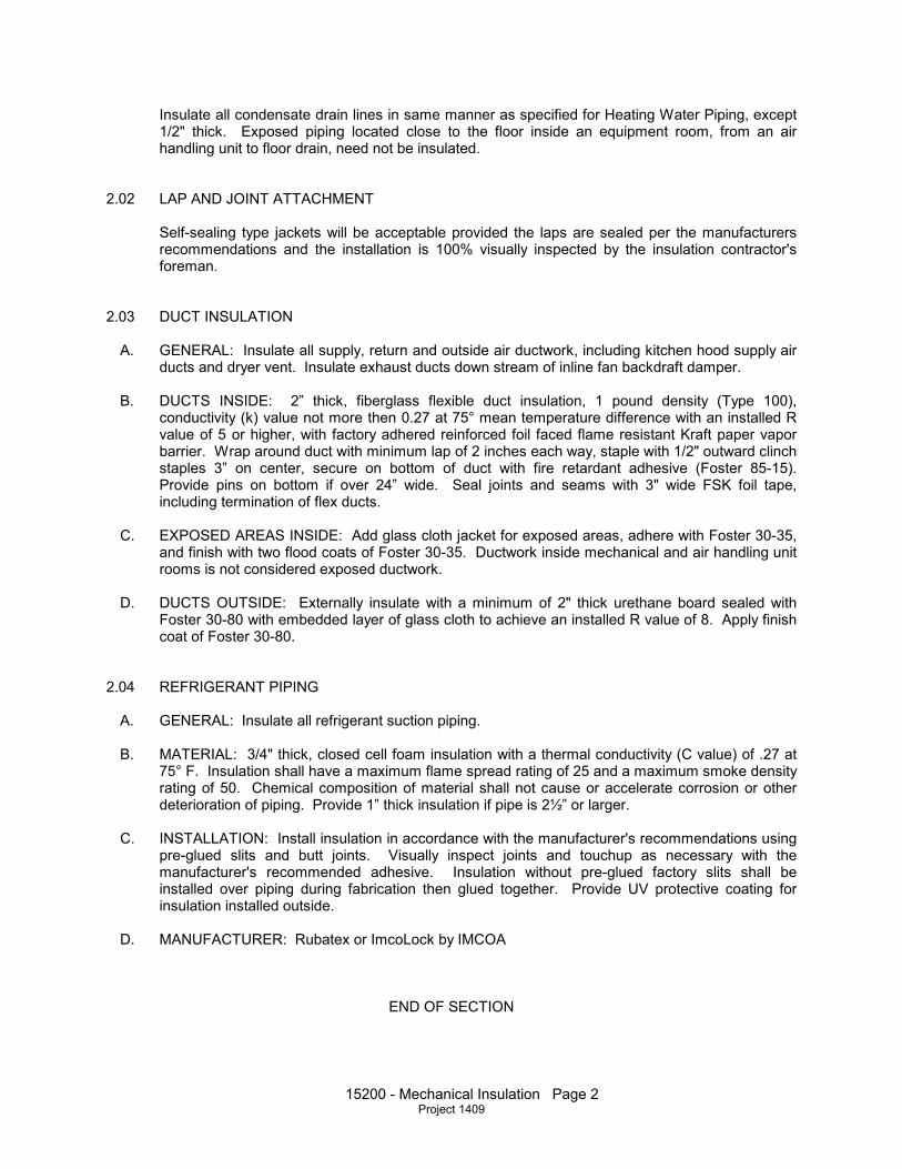
Insulate all condensate drain lines in same manner as specified for Heating Water Piping, except 1/2" thick. Exposed piping located close to the floor inside an equipment room, from an air handling unit to floor drain, need not be insulated.
2.02 LAP AND JOINT ATTACHMENT
Self-sealing type jackets will be acceptable provided the laps are sealed per the manufacturers recommendations and the installation is 100% visually inspected by the insulation contractor's foreman.
2.03 DUCT INSULATION
A. GENERAL: Insulate all supply, return and outside air ductwork, including kitchen hood supply air ducts and dryer vent. Insulate exhaust ducts down stream of inline fan backdraft damper.
B. DUCTS INSIDE: 2” thick, fiberglass flexible duct insulation, 1 pound density (Type 100),
conductivity (k) value not more then 0.27 at 75° mean temperature difference with an installed R value of 5 or higher, with factory adhered reinforced foil faced flame resistant Kraft paper vapor barrier. Wrap around duct with minimum lap of 2 inches each way, staple with 1/2" outward clinch staples 3” on center, secure on bottom of duct with fire retardant adhesive (Foster 85-15). Provide pins on bottom if over 24” wide. Seal joints and seams with 3" wide FSK foil tape, including termination of flex ducts.
C. EXPOSED AREAS INSIDE: Add glass cloth jacket for exposed areas, adhere with Foster 30-35,
and finish with two flood coats of Foster 30-35. Ductwork inside mechanical and air handling unit rooms is not considered exposed ductwork.
D. DUCTS OUTSIDE: Externally insulate with a minimum of 2" thick urethane board sealed with
Foster 30-80 with embedded layer of glass cloth to achieve an installed R value of 8. Apply finish coat of Foster 30-80.
2.04 REFRIGERANT PIPING
A. GENERAL: Insulate all refrigerant suction piping. B. MATERIAL: 3/4" thick, closed cell foam insulation with a thermal conductivity (C value) of .27 at
75° F. Insulation shall have a maximum flame spread rating of 25 and a maximum smoke density rating of 50. Chemical composition of material shall not cause or accelerate corrosion or other deterioration of piping. Provide 1” thick insulation if pipe is 2½” or larger.
C. INSTALLATION: Install insulation in accordance with the manufacturer's recommendations using
pre-glued slits and butt joints. Visually inspect joints and touchup as necessary with the manufacturer's recommended adhesive. Insulation without pre-glued factory slits shall be installed over piping during fabrication then glued together. Provide UV protective coating for insulation installed outside.
D. MANUFACTURER: Rubatex or ImcoLock by IMCOA
END OF SECTION

15650 - Mechanical Equipment Page 1 Project 1409
SECTION 15650 - MECHANICAL EQUIPMENT PART 1 - GENERAL 1.01 RELATED DOCUMENTS The General Provisions of the Contract, including General, Supplementary and Special
Conditions, apply to the work specified in this Section. 1.02 GENERAL REQUIREMENTS Provide motor starters and controllers for motors provided under this Section. Refer to Section
Miscellaneous Equipment and Requirements for starter and motor requirements. Equipment and accessories shall be prewired at the factory for single point connection by the electrical subcontractor.
1.03 EQUIPMENT NAMEPLATES Each piece of equipment shall have a stainless steel nameplate with engraved or stamped 1/32"
deep markings identifying manufacturer, model number, serial number, voltage, phase, amperage, refrigerant type, etc. as applicable. Attach to equipment with a minimum of two stainless steel fasteners.
PART 2 - MATERIALS AND METHODS 2.02 AIR FILTER
A. GENERAL: Provide complete sets of air filters for all equipment for use during construction. Protect filters during construction with an overlay of polyester filter media. Replace overlay filter media and filters during construction as necessary to protect coils. Install a set of new filters prior to Testing and Balancing of the system. Install a final set of new filters at Substantial Completion.
B. FILTER MEDIA: Farr Type 30-30 medium efficiency, pleated, disposable type filter, 2" thick, 30%
efficient on ASHRAE Test Standard 52-76, suitable for face velocity up to 350 FPM with initial resistance not more than .17" w.g. at that velocity. Use .5" w.g. resistance in fan motor selection.
2.03 ROOF FANS AND VENTS
A. GENERAL: Furnish and install as indicated and scheduled on the plans. Capacities and sizes shown are the minimum required. Fans shall bear the AMCA seal of certified ratings for air and sound performance. Fans and their accessories shall be a prewired assembly from the factory for single point connection by the electrical subcontractor.
B. DESIGN: Fans shall be low silhouette type with removable top for easy access. Housings shall
be constructed of heavy gauge aluminum. Kitchen fans shall have grease trough, discharge air vertically from a minimum of 40 inches above roof and be mounted on 18" high curb per NFPA
96, and shall be U. L. 762 Listed up to 400° F. Power assemblies shall be completely removable as a unit for ease of service.

15650 - Mechanical Equipment Page 2 Project 1409
C. DRIVE: Belt drive with heavy cast iron sheaves, adjustable drive sheave and adjustable motor plate. Centrifugal fans shall have motor out of the air stream, cooled by outside air.
D. FAN: Centrifugal fans shall have aluminum, backward curved, non-overloading wheel. Propeller
fans shall be of heavy aluminum construction with a minimum of five blades set in a smooth venturi orifice.
E. ROOF CURBS: Mount on insulated, welded prefabricated aluminum roof curb (galvanized steel if
on steel decking) with integral cant strip. Curbs shall be designed to mount fan level on sloped roof and be compatible with roof construction specified under the Architectural Sections of the Specifications. Insulation of supply fans shall have a smooth, cleanable surface. Securely attach fans and hoods to curb with two bolts on each side. Bolt curb to structure.
F. KITCHEN HOOD FANS: Fans shown to have both a supply and exhaust fan mounted on a
common curb shall have separate electrical connections and associated disconnect switches for each fan. Starters will be remote mounted and are not a part of the fan assembly. Outside air intake duct shall be sufficiently long to provide 10 feet separation between exhaust and intake even if installed perpendicular to rather than inline with the fan curb.
G. ACCESSORIES: All fans shall have built-in thermal overloads, disconnect switch and bird screen.
Backdraft dampers shall be aluminum construction with nylon bushings. Provide additional accessories as noted on the Drawings.
H. HOODS: Provide roof intakes and relief hoods of similar construction, features and installation as
fans. I. ACCEPTABLE MANUFACTURERS: Acme, Cook, Greenheck, Jenco, Penn, Twin City Fans
2.04 MISCELLANEOUS FANS
A. GENERAL: All fans shall be AMCA rated for air and sound. Each fan shall have fan blade and drive guards, disconnect switch and mounting isolators where applicable. Belt drive fans shall have adjustable motor base plates and adjustable cast iron drives sized for 150% of motor horsepower. Dampers shall be aluminum construction with stainless steel shafts and Teflon bushings. Fans and their accessories shall be a prewired assembly from the factory for single point connection by the electrical subcontractor.
B. ACCEPTABLE MANUFACTURERS: Acme, Cook, Greenheck, Jenco, Penn, and Twin City Fans
2.05 DUCT FREE SPLIT SYSTEM
A. GENERAL: System shall consist of outdoor condensing unit connected to one or more duct free, wall or ceiling mounted fan coil units. System shall be designed to operate as a unit complete with microprocessor control system.
B. AIR COOLED CONDENSING UNIT
1. HOUSING: Cabinet shall be constructed of galvanized steel, bonderized and coated with baked-enamel finish. Provide access panels for ease of service.

15650 - Mechanical Equipment Page 3 Project 1409
2. COMPRESSOR: Fully hermetic reciprocating or scroll type operating with R-22 refrigerant. Unit shall have internal protection for over temperature and over current. Provide crankcase heater. Refrigeration system shall have gage ports, service valves, accumulator, filter dryer and pressure relief. Heat pump units shall have reversing valve and heating mode metering device.
3. CONDENSER FAN: Direct drive propeller type with internally protected, totally enclosed
motor. 4. CONTROLS AND SAFETIES: Unit shall have time delay restart, automatic restart on power
failure, safety lockout, high and low pressure safeties. C. EVAPORATOR UNIT
1. GENERAL: Indoor, ceiling or wall mounted, direct expansion fan coil unit complete with electric controls, microprocessor control system and integral temperature sensing.
2. FAN: Direct drive tangential blower with automatic motor-driven vertical air sweep. Fan
motor shall be three speed type. 3. COIL: Copper tube aluminum fin with refrigerant metering device. Provide condensate
drain pan and drip pan under headers. 4. CONTROLS: Shall be microprocessor-based and control space temperature, determine
optimum fan speed and run self-diagnostics. Provide remote wireless controller for programming and temperature adjustment.
5. FILTERS: Factory supplied, permanent cleanable type with rack.
D. ACCEPTABLE MANUFACTURERS: Carrier, Daikin, Mitsubishi and Sanyo.
2.06 SELF CONTAINED ROOM AIR CONDITIONING UNIT
A. GENERAL: The system shall be designed to control temperature and relative humidity conditions within the room. The manufacturer shall design and furnish all equipment in the quantities and configurations shown on the project drawings. The self-contained shall be designed for above-dropped-ceiling installation and serviceable from the front and bottom of the system. Condensing unit for split system shall be designed for outdoor installation. See the schedule on the construction documents for design capacity and electrical requirements.
B. EQUIPMENT FEATURES:
1. CABINET CONSTRUCTION: The cabinet and chassis shall be constructed of heavy gauge galvanized steel and designed for easy installation and service access from front and bottom of unit only (water cooled units require end access). Mounting brackets shall be factory-attached to the cabinet. Internal cabinet insulation shall meet ASHRAE 62.1 requirements for Mold Growth, Humidity & Erosion, tested per UL 181 and ASTM 1338 standards.
2. AIR DISTRIBUTION: The air distribution system shall be constructed with a quiet, direct-drive fan assembly equipped with double-inlet blower, self-aligning ball bearings and lifetime lubrication. Fan motor shall be 1/5hp (149W), permanent-split capacitor, high efficiency type, equipped with two speeds for air flow modulation for precise dehumidification control. Dehumidification shall utilize the lower fan speed.

15650 - Mechanical Equipment Page 4 Project 1409
3. MICROPROCESSOR CONTROL: The control system shall be microprocessor-based, factory-wired into the system and tested prior to shipment. The wall-mounted control enclosure shall include a 2-line by 16-character LCD providing continuous display of operating status and alarm condition. An 8-key membrane keypad for setpoint/ program control, fan speed selection and unit On/Off shall be located below the display. The control display shall be field-wired to the control board using 4-conductor field-supplied thermostat wire. Temperature and humidity sensors shall be located in the wall box, which shall be capable of being located up to 300 ft (91.4m) from the evaporator unit.
i. MONITORING: The LCD shall provide On/Off indication, operating mode indication (cooling, heating, humidifying, dehumidifying), fan speed indication and current day, time, temperature and humidity (if applicable) indication.
ii. CONTROL SETPOINT PARAMETERS:
1) Temp. Setpoint 65-85°F (18-29°C)
2) Temp. Sensitivity 1-9.9 °F (1-5°C)
3) Humidity Setpoint 20-80% RH
4) Humidity Sensitivity 1-30% RH
iii. UNIT CONTROLS:
1) COMPRESSOR SHORT CYCLE CONTROL: The control system shall prevent compressor short-cycling by a 3-minute timer from compressor stop to the next start.
2) COMMON ALARM AND REMOVE ON/OFF: A common alarm relay shall provide a contact closure to a remote alarm device. Two (2) terminals shall also be provided for remote On/Off control. Individual alarms shall be “enabled” or “disabled” from reporting to the common alarm.
3) SETBACK CONTROL: The control shall be user-configurable to use a manual setpoint control or a programmable, time-based setback control. The setback control will be based on a 5 day/2 day programmed weekly schedule with capability of accepting 2 events per program day.
4) TEMPERATURE CALIBRATION: The control shall include the capabilities to calibrate the temperature and humidity sensors and adjust the sensor response delay time from 10 to 90 seconds. The control shall be capable of displaying temperature values in °F or °C.
5) SYSTEM AUTO RESTART: For startup after power failure, the system shall provide automatic restart with a programmable (up to 9.9 minutes in 6-second increments) time delay. Programming can be performed either at the wall-mounted controller or from the central, site-monitoring system.
4. ALARMS: The control system shall monitor unit operation and activate an audible and visual alarm in the event of the following factory preset alarm conditions:
1) High Temperature
2) Low Temperature

15650 - Mechanical Equipment Page 5 Project 1409
3) High Humidity
4) Low Humidity
5) High Water Alarm - Lockout Unit Operation
6) High Head Pressure
7) Loss of Power
8) Compressor Short Cycle
5. DIRECT EXPANSION SELF-CONTAINED SYSTEM COMPONENTS
i. REFRIGERATION SYSTEM: The refrigeration system shall consist of a (scroll) (rotary) compressor with vibration isolating grommets, evaporator coil, condenser coil, externally equalized thermostatic expansion valve, high pressure safety switch, filter drier, hot gas bypass circuit, factory R-407C refrigerant charge and externally equalized expansion valve. Hot gas bypass shall be provided to reduce compressor cycling and optimize performance under low load conditions.
ii. EVAPORATOR COIL: The evaporator coil shall be constructed of copper tubes and aluminum fins and have a maximum face velocity of _500 ft. per. The coil shall be provided with a condensate drain pan with an internally trapped drain line. The evaporator drain pan shall include a factory-installed float switch to shut down the evaporator upon high water condition.
iii. AIR COOLED CONDENSER COIL: The air-cooled condenser section shall contain a factory mounted and piped condenser coil constructed of copper tubes and aluminum fins. No piping, brazing, dehydration or charging shall be required. The condenser coil shall be factory-mounted within the unit cabinet.
iv. AIR COOLED CONDENSER FAN: A factory-supplied condenser fan shall be field-mounted to the end of the evaporator cabinet. The system shall be provided with a fan speed control system to permit operation at -20°F (-28.9°C) inlet ambient air temperature and sized to provide full rated cooling capacity at 95°F (35°C) entering air from plenum space.
6. FACTORY INSTALLED OPTIONS:
i. DISCONNECT SWITCH, NON-LOCKING: The non-automatic, non-locking, molded case circuit interrupter shall be factory mounted in the high-voltage section of the electrical panel. The switch handle shall be accessible from the unit front and mounted on the indoor cooling unit.
ii. FILTER CLOG SWITCH: The filter clog switch senses pressure drop across the filters and shall annunciate the wall-box display upon reaching the adjustable setpoint.
7. FIELD INSTALLED ACCESSORIES:
i. REMOTE SENSORS: The unit shall be supplied with remote temperature and humidity sensors. The sensors shall be connected to the unit by a 30 ft. (9m) shielded cable.
15650 - Mechanical Equipment Page 6 Project 1409
ii. FILTER BOX AND DUCT KIT: A return air filter box shall be provided with hinged filter access, and 1" (25.4 mm) duct flange. A 1" (25.4 mm) duct flange shall also be provided for air discharge. Filters shall be 1" x 16" x 20" (25.4mm x 406mm x 508mm) MERV 8 per ASHRAE 52.2-2007.
iii. CONDENSATE PUMP: The condensate pump be complete with integral float switch, discharge check valve, pump, motor assembly and reservoir. A secondary float switch shall be provided to permit field wiring to the unit control to shut down the evaporator upon a high water level condition.
C. INSTALLATION REQUIREMENTS
1. GENERAL: Install air conditioning unit in accordance with manufacturer's installation instructions. Install unit plumb and level, firmly anchored in location indicated, and maintain manufacturer’s recommended clearances.
2. ELECTRICAL WIRING: Install and connect electrical devices furnished by manufacturer but not specified to be factory-mounted. Furnish copy of manufacturer’s electrical connection diagram submittal to electrical contractor. Install and wire per local and national codes.
3. PIPING CONNECTIONS: Install and connect devices furnished by manufacturer but not specified to be factory-mounted. Furnish copy of manufacturer’s piping connection diagram submittal to piping contractor.
4. DRAIN WATER PIPING: Connect water drains to air conditioning unit. Unit drain shall be trapped internally and shall not be trapped externally.
5. FIELD SUPPLIED PAN: A field-supplied pan with drain shall be installed beneath ducted cooling units.
6. FIELD START-UP: Startup air conditioning unit in accordance with manufacturer’s startup instructions. Test controls and demonstrate compliance with requirements.
END OF SECTION

15800 - Air Distribution Page 1 Project 1409
SECTION 15800 - AIR DISTRIBUTION PART 1 - GENERAL 1.01 RELATED DOCUMENTS The General Provisions of the Contract, including General, Supplementary and Special
Conditions, apply to the work specified in this Section. PART 2 - MATERIALS AND METHODS 2.01 DUCTWORK
A. Furnish and install all supply, return, exhaust, outside air and other ductwork shown, together with splitters, extractors, dampers, etc. All ductwork, supports, bracing, etc. shall be constructed of new grade, lock forming quality, G-60 or better galvanized steel sheets.
B. Dimensions of duct work shown on Drawings are inside air stream dimensions. Allowances have
not been made for duct insulation. C. Provide balancing OBD in each zone duct of multi-zone AHU's. Provide adjustable extractors with
quadrant lock mechanism equal to Titus AG-45 at all supply outlet taps into trunk duct. Provide conical tap with damper and raised quadrant lock for flexible duct taps, reference detail on the
Drawings. Provide adjustable round elbows (0-90°) at ceiling devices connected with flex ducts. D. Ductwork shall conform with current edition of SMACNA "Duct Manual and Sheet Metal
Construction for Ventilating and Air Conditioning System" and the National Board of Fire Underwriters Pamphlet 90A, plus more stringent requirements of these Specifications. Adjust location of standing seams to clear structural members.
E. All duct transitions shall be gradual with a 15° maximum angle as measured from centerline of duct. This includes angled offset, mitered offset, eccentric transition and concentric transition (2 x
15°). F. Ductwork operating at greater than 1.0 static pressure, as specified under "external static
pressure" of the associated air handling unit schedule, or primary ductwork from a variable air volume air handling unit shall be constructed in accordance with Section 2.02 Medium Pressure Ductwork.
G. Square turns shall be equipped with double thickness turning vanes built to SMACNA Standards.
Provide radius turns for elbows less than 90°. H. Support ductwork with 1" wide x 20 gage galvanized steel straps; 6'-0" maximum centers but not
more than allowed by SMACNA. Connect strap to duct with two sheet metal screws on each side of duct and one on bottom. Exposed ducts shall be supported in a manner to provide a finished appearance.
I. Install duct braces in duct openings to hold shape of duct until grilles, registers and/or diffusers
are installed. Then remove duct brace.

15800 - Air Distribution Page 2 Project 1409
J. Seal all duct joints, adjustable elbows and spin-in taps with Design Polymerics DP1010 or Hardcast IG601 Iron Grip installed full strength (no dilution). Ductwork subject to moisture and not required to be welded, shall be sealed with Benjamin Foster 3214.
K. Flexible duct shall be U. L. Listed 181 Class I air duct with fiberglass/aluminum foil inner liner,
fiberglass insulation with a C=.23, bi-directional reinforced metalized vapor barrier outer jacket and 6" w.c. pressure rating. The insulating value shall be meet the International Energy Code, minimum R=6. The maximum length between duct and air device shall be six feet. The maximum length between duct and single or double duct mixing box shall be three feet. Flexmaster Type 3M or Thermaflex M-KE. Connect inner liner to duct tap, VAV box, round rigid duct or air device with stainless steel, adjustable bands (hose clamps). Secure outer cover with nylon wire tie strap. Tape edges of outer cover to adjacent insulation or duct with FSK foil tape to present a finished appearance.
L. In areas noted to have round double wall ductwork, provide United McGill Acousti-K27. Outer
duct shall be constructed of paintable, 18 gauge galvanized steel. Inner duct shall be perforated galvanized steel. Between the inner and outer ducts install 2” thick fiberglass insulation coated to inhibit growth of micro-biological organisms and to eliminate erosion of fibers.
M. The minimum distance between the CVT box and the first tap shall be 54”. The minimum
distance between taps on the same side of the duct shall be 54”. N. Provide equivalent sized duct of different aspect ration to accommodate ceiling cavity conditions. O. Sheet metal contractor shall install control system and fire alarm system devices that are attached
to ductwork. This includes control dampers, sensors and duct smoke detectors. 2.02 DUCTWORK FOR OUTSIDE AIR HOODS AND FANS
Where hoods or fans are shown open to mechanical room, shop, etc., provide short length of duct to allow installation of OBD and/or motorized control damper. Duct dimension shall be roof curb opening size or larger if required by damper size.
2.03 PLENUMS AND BLANK-OFF PLATES
A. Provide plenums at louvers, air handling units, fan coil units and other equipment where return air or outside air ducts are shown to connect. Provide plenums for the mounting fans to louvers. Provide full or partial blank-off plates on return air openings as necessary for properly balancing of system supply air, outside air and return air flows or to cover openings where air transfer is not desired.
B. Construct plenums with galvanized steel framing members and galvanized sheet steel, cross
broken or rigidly braced with galvanized angles. Gages and bracing shall conform to SMACNA recommendations for ductwork of like size. Openings for fans, access doors, etc., shall be framed with galvanized steel angles.
C. Where access doors are shown, provide hinged doors with #202 Ventlok latch.
2.04 SHEET METAL SHOP DRAWINGS

15800 - Air Distribution Page 3 Project 1409
Prior to fabrication of any sheet metal, submit Shop Drawings for all ductwork, showing coordination of mechanical, electrical, plumbing and structural components. All crafts shall sign off on final drawings. The shop drawing shall include a construction details booklet (multiple copies), one blueline set of drawings and one reproducible set of drawings. The booklets and reproducible set with comments noted will be returned. Contractor shall provide blueline sets of drawings from the reproducible set for distribution to Owner, Architect and others.
2.05 FLEXIBLE CONNECTIONS BETWEEN AHU, VAV BOX OR FAN AND DUCTWORK
Flexible connections shall be made from neoprene coated, woven glass fiber material, 30 ounce per square yard, installed air tight with at least 1" slack to insure that no vibration is transmitted from fan to ductwork. Air handling units with fans that are internally isolated from the housing do not require flexible connections.
2.06 SCREENS
Furnish and install screen on all duct, fan, etc., openings which lead to or are outdoors. Screens shall be No. 16 gage, galvanized steel 1/2" mesh bolted into removable galvanized steel frame. Install screens over return air openings between floors.
2.07 CONNECTIONS TO LOUVERS
All connections to louvers shall be in a manner that will be watertight. Ductwork behind louver for a minimum of three feet shall have watertight soldered joints and shall be sloped to weep holes in bottom of louver. Duct shall be lapped over bottom louver blade where possible. Make connections to aluminum louvers with dielectric connections.
2.08 DAMPERS
A. GENERAL: Provide dampers where shown on Drawings and wherever necessary for complete control of air flow, including all supply and outside air ducts. Provide multi-blade volume dampers in all zone ducts at multi-zone air handling units. Where access to dampers through a suspended ceiling is necessary, coordinate the proper location of the access doors. Install, mount and connect into ductwork all control dampers furnished under the control contractors supervision.
B. SPLITTER DAMPERS: Shall be constructed of single thickness, 16 gauge galvanized steel,
hinged at leaving edge and founded at entering edge, securely riveted or welded to a square operating rod. The length of the splitter damper blade shall be 1½ times the width of the split in the main duct, but not less than 12".
C. VOLUME DAMPERS: Factory constructed of 16 gage galvanized steel for frame and blades.
Blades shall not exceed 48" in length or 6" in width, and shall be of the opposed interlocking type. The blades shall be supported on 1/2" diameter rust-proofed axles. Axle bearings shall be self-lubricating ferrule type.
D. FLEX TAP CONNECTIONS: Taps on rectangular low pressure ducts for flexible connections to
diffusers, etc shall be 22 gauge, round conical taps with adjustable single blade damper. Damper rod shall be continuous though tap with blade mechanically attached. Provide bearings at each end, and quadrant lock operator with wingnut and 2” standoff bracket for insulation. Refer to detail on the drawings for additional construction details.

15800 - Air Distribution Page 4 Project 1409
E. DAMPER ADJUSTING DEVICES: Each splitter or volume damper shall be fitted with an adjusting device extending beyond external duct insulation.
1. ACCESSIBLE CEILINGS: Ventlok #641 regulators attached directly to duct and location
marked in ceiling as approved. 2. NON-ACCESSIBLE CEILING: Regulators exposed. Ventlok #666 rods and #607 end
bearings.
2.09 FIRE DAMPERS
A. Install fire dampers in all duct penetrations and return air openings in fire rated walls, ceilings, floors and chases. Provide fire damper at each sidewall register or grille. Provide additional fire dampers where specified by local building codes and also where shown on drawings.
B. Construction shall conform to requirements of NFPA Pamphlet No. 90A with recommended steel
sleeves, fusible links, spring catches, non-corrosive bearings, etc., and shall be U. L. labeled. C. Fire dampers shall be shutter type providing minimum restriction to air flow. Provide Type B for
ducts passing through walls. Provide thinline Type A dampers at sidewall registers. Provide Type B (or Type A of equal free area) dampers at wall openings. Select damper thickness to fit within the thickness of the wall with OBD's or other specified devices. Dampers located in medium pressure ducts shall be compatible with this construction including the specified maximum leakage rate. Install dampers in accordance with conditions of their U. L. listing.
D. Air devices in U. L. fire rated ceilings shall have compatible U. L. classified ceiling dampers with
volume adjustment mechanism and extension collar equal to Ruskin CFD-A. Install complete system including thermal blanket on back of air device in accordance with the U. L. listing.
E. Acceptable Manufacturers: Greenheck, Nailor, Pottoroff, Ruskin and Safe-Air
2.10 ACCESS DOORS TO FIRE DAMPERS
A. Provide double wall galvanized steel, insulated access door in duct for inspection and service to fire damper and fusible link. Minimum size shall be 16"x16" with four cam latches unless limited by duct size. Access doors in stainless steel ducts shall be constructed of stainless steel.
B. Construct access door airtight and conform to recommendations of NFPA and SMACNA. C. Opening of access panel shall be within 12” of the damper to allow resetting of the actuator.
2.11 METAL CLOSURES
A. Provide metal closures around all openings in floors or walls through which ducts or piping are passing.
B. Build 3" high by 3" wide concrete "dam" around duct or return air penetrations of mechanical room
floors above grade. Floor return air openings without sound attenuator attached shall be covered with 1" x 1/8" welded steel bar grating supported by 2" x 2" x 1/4" angles attached to slab with 3/4" round drilled anchors, 24" on center.
C. MATERIALS:
15800 - Air Distribution Page 5 Project 1409
1. Where no fire rating required, and where no fire dampers installed: 18 gage galvanized sheet metal.
2. Where fire rating required or where fire damper is installed: Gage of sleeves shall be as
required by the conditions of U. L. listing, but not less than the gage of duct. Minimum 18 gage. Install 1½" x 1½" x 1/8" angles around duct on both sides of wall or floor penetration.
3. Sleeves for floor pipe penetrations above grade shall be a section of Schedule 40 steel pipe
extending 3" above finished floor and sealed watertight.
2.12 SADDLES
Provide sheet metal protective saddles at all pipe supports for insulated piping. Refer to Insulation Section.
2.13 AIR DEVICES
A. Furnish and install louvers, supply, return and exhaust registers, grilles and outlets shown on the Drawings.
B. All devices shall be all aluminum construction and shall have white finish. Aluminized type
corrosion resistant steel with finish having a five year warranty against the formation of visible rust will also be acceptable. Devices in U. L. fire rated ceilings shall be of aluminized steel construction with white finish, suitable for U. L. classification.
C. All supply outlets shall be equipped with opposed blade volume dampers. Provide Titus Model D-
75 for supply diffusers. D. The air distribution equipment supplier shall guarantee that each supply, return and exhaust
device shall be of the proper design and size to pass the indicated quantity of air into or out of the space involved, with maximum diffusion and without objectionable noise, excessive friction or objectionable air movement at the occupied level.
E. Registers, grilles and outlets shall be of manufacture, type and capacity as shown on the schedule
of the Drawings. Similar devices of other manufacture may be submitted for approval for those items for which a reasonable close substitute is available. Devices must be similar in appearance and their style must be acceptable to the Architect.
F. If devices other than those shown are proposed, the values for their face velocities, neck
velocities and noise levels, DBA or NC, shall not exceed these values for the devices scheduled on the Drawings.
G. Ceiling outlets shall be of a type compatible with the ceiling in which they are installed and shall
have removable core with overlapping cone design to prevent vertical downward projection of air. H. Contractor shall check the Architectural Drawings and verify the type of ceiling shown in the
various areas to determine the proper type of outlet for the ceiling used. I. Air devices in U. L. fire rated ceilings shall have compatible U. L. classified ceiling dampers with
volume adjustment mechanism and have U. L. approved fireproofing on device. Dampers connected to flexible ducts shall also have extension collar feature equal to Ruskin CFD-A. Sidewall registers shall have thinline fire damper. Fire proofing devices shall contain no friable or fibrous material in the air stream.

15800 - Air Distribution Page 6 Project 1409
J. ACCEPTABLE MANUFACTURERS: Krueger, Metalaire, Nailor, Price and Titus.
2.14 DRAIN PANS
A. GENERAL: Provide drain pan under fan coil units, air handling units, water heaters and other equipment subject to water leakage not mounted on concrete floor in mechanical room.
B. CONSTRUCTION: 16 gauge galvanized steel suitably stiffened, with minimum 2" perimeter lip
and all joints soldered watertight. Provide connection and overflow drain to suitable location.
2.15 INSTALLATION OF DUCTWORK AND AIR DEVICES
A. Prior to all work of this section, Carefully inspect the installed work of all other trades and verify that all such work is complete to the point where fabrication and installation of the work of this section may properly commence.
B. Verify the location of all ducts, structure, piping and equipment. Coordinate the routing of all work
with that of other trades prior to installation. Verify that all ductwork will fit spaces indicated prior to fabrication or installation of any ductwork.
C. Exact location of all registers, grilles or ceiling outlets shall be verified by the Architect before
roughing-in. Reference shall be made to reflected ceiling plan in locating ceiling outlets. D. Ducts shall be installed in a neat and workmanlike manner.
2.16 ADJUSTMENTS AND CORRECTIONS
Balance all systems of ductwork including exhaust systems to obtain the air quantities indicated for each inlet and outlet. Air quantities shall be further adjusted as required to obtain uniform temperatures in the spaces.
2.17 ACOUSTICAL LINER
A. GENERAL: Provide 1" thick acoustical lining in return air ducts and return air plenums. Do not install in any supply air duct or kitchen return air duct.
B. MATERIAL: Owens-Corning "Aeroflex Duct Liner" or equivalent by CertainTeed; 1½ pound per
cubic foot density, neoprene faced, "K" value not more than .27 at 75° F mean temperature difference.
C. INSTALLATION: Adhere liner, with coated side toward air stream, to all interior sides of duct with
100% coverage of Foster 85-11. Further secure the liner with mechanical fasteners on maximum 12" centers. All edges and fasteners shall be coated with one brush coat of Foster 30-35.
D. PLENUMS: Plenum interiors exposed to view through louvers and grilles shall be lined and have
pins painted flat black.
END OF SECTION

16050 General Electrical Page 1 Project 1409
SECTION 16050 - GENERAL ELECTRICAL PART 1 - GENERAL 1.01 RELATED DOCUMENTS The General Provisions of the Contract, including General, Supplementary and Special
Conditions, apply to the work specified in this Section. 1.02 GENERAL REQUIREMENTS Provide all supervision, labor, equipment and materials required for the installation of complete
and operating electrical systems in the building. Pay all fees and obtain all permits related to construction activities and utility service installation.
1.03 GUARANTEE All materials, apparatus and equipment furnished and installed under this Section of these
Specifications shall be new and free from any defects when accepted by the Owner and shall be guaranteed in writing for a period of one year from the date of acceptance by the Owner.
1.04 COORDINATION
A. Coordinate work of this Division with that of other Divisions so that various components of the building will be installed at the proper time, will fit the available space and will allow proper service access to those items requiring maintenance. This means adequate access to all equipment not just that installed in this Section.
B. Where various items of equipment and materials are specified and scheduled, the purpose is to
define the general type and quality level, not to set forth the exact trim required to fit the various types of ceiling, wall or floor finishes. Provide materials which will fit properly the types of finishes actually installed.
1.05 DRAWINGS
A. The drawings indicate approximate locations of the various items of electrical systems. These items are shown approximately to scale and attempt to show how these items should be integrated with building construction. Locate all the various items by on-the-job measurements, conformance with Contract Documents and cooperation with other trades.
B. Prior to locating light fixtures, confer with Owner as to desired method of locating fixtures in the
various areas. In no case should fixture locations be determined by scaling drawings. C. All light fixtures, speakers and other ceiling devices shall be located to conform to the ceiling grid
system. Examine all drawings to become familiar with this requirement. Lighting fixtures in mechanical spaces are shown in their approximate location only. Do not install light fixtures until mechanical piping and ductwork is installed, then install lights in a location to provide best lighting.
D. In certain instances, the Owner may require relocation of outlets, switches, etc. Where relocation

16050 General Electrical Page 2 Project 1409
is within five feet of location shown on drawings, and when Contractor is informed of necessary relocation before work is begun on this portion of the job, no extra compensation will be allowed.
E. The drawings are schematic in nature and are not intended to show exact locations of conduit,
but rather to indicate distribution, circuitry and control.
1.06 INTENT OF DRAWINGS AND SPECIFICATIONS
The drawings and specifications are intended to be complimentary. Any work exhibited in either of them, whether in the other or not, is to be executed according to the true intent and meaning thereof, the same as if set forth in all.
1.07 ALTERNATES Determine the scope of each specified alternate proposal by carefully reading all Divisions of the Documents. The Bid Form contains information explaining the extent of the construction to be performed under a specific alternate. Alternate proposals, which are not predominantly electrical in scope, are described in other Divisions of these Documents.
1.08 CODES All materials and their installation shall be in accordance with the 2011 National Electrical Code, local building codes and the current edition of the National Electrical Safety Code (NFPA 70e) for safety in the workplace. Nothing in the plans and specifications shall be construed to permit work not conforming to the most stringent of the codes. Particular attention shall be paid to the U. L. codes for fireproofing of conduit, electrical devices and light fixtures that are part of or pass through fire rated ceilings, walls and floors.
1.09 VISITING THE SITE The Contractor shall be familiar with the Drawings and Specifications and shall have examined
the premises and understand the conditions under which he will be obligated to operate in performing the contract. No allowance shall be made consequently for any error through negligence in this regard.
1.10 ELECTRICAL SERVICE A. The service characteristics are 480Y/277V, 3 phase, 4 wire. The Power Company is CenterPoint
Energy.
1.11 TEMPORARY SERVICE
Provide a temporary electrical service for construction power. Size and voltage as required for construction activities as specified by the General Contractor. Construction site distribution shall be overhead and comply with the 2011 NEC, OSHA Standards and the current edition of the National Electrical Safety Code (NFPA 70e) for safety in the workplace. Remove all temporary wiring upon project completion.

16050 General Electrical Page 3 Project 1409
1.12 GENERAL REQUIREMENTS FOR ALL MATERIALS A. Provide all parts and accessories necessary for equipment and complete installation. B. Provide factory applied finish on all exterior surfaces of electrical equipment. Any item which has
the finish marred must be refinished to a new condition before final acceptance. C. Provide three copies of spare parts lists and operating and maintenance instructions for all
distribution apparatus, major equipment and auxiliary systems. These shall be bound in folders with suitable identification on front cover. Deliver to Owner prior to final acceptance.
D. All materials must be new and of good quality and shall bear the stamp of approval of the
Underwriters' Laboratories, Inc. (U. L.). Equipment and materials shall be used and installed consistent with the U. L. testing and U. L. requirements. All materials shall be certified to not contain any asbestos, PCB's or other material banned by the Environmental Protection Agency.
1.13 ELECTRICAL SUBMITTALS A. The purpose of these submittals is to attempt to aid the contractor in such a manner that
improper or unacceptable materials are not delivered to or installed on the job. Approval of these submittals shall not be construed as releasing The Contractor from compliance with the Contract Documents. All materials and equipment shall be subject to final acceptance by the Engineer at completion of construction.
B. Equipment and material submittals must show sufficient data to indicate complete compliance
with contract documents as follows:
1. Proper sizes and capacities. 2. That the item will fit in the available space in a manner that will allow proper service. 3. Construction methods, materials and finishes.
C. Catalog data must be clearly marked to indicate the item or model number being submitted and
must include all specified accessories. All information on a catalog sheet not pertaining to the item being submitted must be marked out.
D. All submittals must be bound in book form with a table of contents listing all items in that specific
submittal. Loose catalog sheets or drawings will not be acceptable. All submittals on the project need not be submitted in one book. The front sheet of each copy of the submittal shall have the following typed information: 1. Job name and location. 2. General Contractor's name, address, Project Manager's name and telephone number. 3. Submitting Sub-contractor's name, address, Project Manager's name and telephone
number. 4. Supplier's company name, address, salesman's name and telephone number. 5. Signature of an officer or attorney-in-fact of the Sub-contractor with date and title and a
statement that the submittal materials and equipment complies with the contract Documents.
Any submittal without all of the above information will be rejected without review.
E. For any item to be installed in or on a finished surface (such as tee bar acoustical ceiling, plaster
wall), Contractor certifies by making the submittal that he has checked all applicable contract Documents and that the item submitted is compatible with the surface finish on which it is to be installed.

16050 General Electrical Page 4 Project 1409
F. Submit shop drawings and/or brochures for:
Panelboards Circuit Breakers Transformers Disconnect Switches Wiring Devices
G. If a submittal is returned to the Contractor marked “Rejected” or “Revise and Resubmit”, only one
(1) additional submittal will be permitted without the Contractor incurring charges for the additional re-submittals. JSE shall be reimbursed by the Contractor for any expense in connection with any necessary submission in addition to the two (2) submissions allowed. Contractor will be billed by JSE at a rate of $125/hr for these occurrences.
1.14 SUBSTITUTIONS
A. The names of manufacturer and model numbers have been used in the Contract Documents to
establish types of equipment and standards of quality and are intended to be the Basis of Bid. If only one manufacturer is named for a specific item of equipment alternate manufacturers shall be acceptable as a substitution/approved equal as specified in this Article.
B. All other brands, including any additional names which may be listed as “Alternates” or “Approved
Equal” must conform with the specifications, size, accessories, etc. of the first named brand and be subject to Paragraph D and E of this Article. Alternate equipment must be equal from the standpoint of materials, construction and performance. Request for substitution must be accompanied by complete data and descriptive sheets during the bidding period as described in Paragraph D and E of this Article.
1. Submited on Bidder’s letterhead attached to Proposal Form with individual deductive
amounts stipulated and the documentation required in Paragraph E-03. 2. All savings for Owners selection of deductive amounts by acceptance of alternate or
substituted items are to be paid to the Owner. C. All equipment within common group or category (e.g. switchgear, lighting fixtures, fire alarm, etc.)
shall be same manufacturer. D. Proposed Substitutions/Approved Equals:
1. Submitted no less than 7 calendar days prior to bid date. 2. Submit proposed substitutions with catalog data and/or manufacturer’s shop details
indicating all modifications required to conform with specified brand. Include all relevant items necessary to make a determination of equal status or submittal shall be deemed incomplete and rejected.
3. If submittal contains sufficient information to prove compliance with the Contract Documents, then that alternate submittal will be acceptable. Approved submittals for bidding purposes only will be published by addenda.
E. Substitutions with prior approval:
1. Submitted on Bidder’s letterhead attached to Proposal Form with individual additive/deductive amounts stipulated and the documentation required in Paragraph B-2.
2. Owner reserves the right to accept or reject any or all substitution proposals before execution of Contract.
3. Provide all design/engineering services required to make adjustments in space, systems, utilities, etc. and pay all additional costs of utilities, construction or professional services that may be incurred due to the acceptance of any substitution.

16050 General Electrical Page 5 Project 1409
1.15 PROTECTION OF EQUIPMENT
A. Do not deliver equipment to jobsite until progress of construction has reached the stage where
equipment is actually needed, or until building is closed in enough to protect equipment from the weather. Equipment allowed to stand in weather will be rejected, and Contractor is obligated to furnish new equipment at no cost to Owner.
B. Adequately protect equipment (including all Owner-furnished items) from damage after delivery to
job. Cover with heavy cloth as required to protect from damage. C. Equipment which has been damaged by construction activities will be rejected. Contractor shall
furnish new equipment at no cost to Owner.
1.16 FOUNDATIONS AND EQUIPMENT SUPPORTS A. GENERAL: Provide all foundations and supports. B. CONCRETE HOUSEKEEPING PADS: 4" high concrete pad to be provided for all floor mounted
equipment. Concrete pads shall be sized for the equipment to be supplied. Pad shall exceed base dimensions by approximately 4" all around. Reinforce pads with 6" x 6" woven wire mesh and #4 bar around perimeter. Tool pad to form chamfered edge.
C. INSIDE ELECTRICAL EQUIPMENT: Securely attach panels to block walls with concrete bolts.
When attaching to sheetrock or other less substantial walls, provide blocking and unistrut cross supports to securely attach panel to structural members. Where panels are required to be freestanding provide angle iron support structure bolted to floor and building structure.
D. VIBRATION ISOLATION: Install dry type transformers on four waffle pad type isolators.
1.17 NOISE Eliminate any abnormal noises which are not considered by the Owner/Engineer to be an inherent part of the systems as designed. Abnormal buzzing in equipment components will not be acceptable.
1.18 TESTING BY CONTRACTOR A. GENERAL: All wiring, instruments, apparatus and equipment shall be tested for continuity,
ground and short circuits before the circuits are energized. For 120 Volts circuits, the neutral/s may require disconnecting. A complete record of all testing shall be submitted to Owner at completion.
B. GROUND TESTING: The resistance of the grounding system to ground shall not exceed 3 ohms
for water pipe ground or 6 ohms for driven ground rods. If tests indicate a higher value, additional ground rods shall be installed to reduce the resistance to a value of 6 ohms or less. Whenever connection is required to an existing ground conductor, tests shall be made before connection to insure that the existing ground conductor is unbroken and continuous. Ground tests shall be performed after at least 7 days of dry weather with test meter supplying a minimum of 50 amps to the ground rod. Auxiliary current electrode shall be approximately 85 feet from ground rod and auxiliary potential electrode shall be 62% of this distance from the ground rod in between the two rods.

16050 General Electrical Page 6 Project 1409
C. INSULATION TESTING: Test all electrical equipment bussing, underground feeders and feeders 1/0 and larger at 85% of rated insulation value. Insulation tests shall be made with a 500 volt "Megger" as manufactured by James G. Biddle Company or equal. Test one conductor at a time with other two grounded. Attempt to raise voltage to maximum in one minute. Do not exceed 2 MA. Polarization Index (amps ratio - 1 minute/10 minutes) to be at least 3 unless approved otherwise.
D. ADDITIONAL TESTING: The Contractor shall make such other tests as may be or become
necessary to assure satisfactory operation of each unit device or equipment.
1.19 RECORD DRAWINGS Obtain a set of project drawings and keep these at jobsite during construction. During the course
of construction, mark on these prints any changes which are made, noting particularly locations for those items which will need to be located for servicing. At completion of job, mark each sheet "Record Drawings", date and deliver to Owner.
1.20 OWNER'S INSTRUCTIONS
Provide the following periods of on site instructions to Owner's designated personnel upon completion of the systems' installation:
Electrical Systems and UPS: 4 Hours 1.21 MOUNTING HEIGHTS
A. GENERAL: Heights are measured to centerline from the finished floor. Where devices are
located in block walls Owner may require height to be adjusted so junction box is in a desired relationship with the mortar joint. Device must still be mounted within the acceptable height range for ADA.
B. DEVICE:
Receptacle 18" 1.22 MEP INSPECTIONS
A. Contractor shall formally request inspections from JSE to review any and all MEP installations.
Inspections shall include but not be limited to: pipe tests, underground installations prior to backfill, rough-in installations, wall cover inspections, above ceiling inspections, final inspection.
B. Information required from Contractor on each and every request for inspection is as follows:
1. Specific type of inspection (i.e. underground conduit installation, wall cover up, fire alarm
demonstration, etc.). 2. Exact location of test (i.e. area of building with wing or room numbers). 3. Description of test (i.e. partial inspection, walls only, chase walls, wall cover, ceiling cover,
etc.) 4. Exact time of any tests that are to be observed. Estimated time test will start will not be
acceptable.

16050 General Electrical Page 7 Project 1409
5. Verification from General Contractor with name of person that verified, that specific test has
been verified by the Contractor and all sub-contractors to meet all requirements of the Specifications and Codes (prior to inspection request).
C. Contractor shall provide a MINIMUM of 48 hour notice prior to requested inspection time, no
exceptions. D. INSPECTION REPORTS: After each inspection, JSE will generate an inspection report and
distribute promptly. The Contractor will then be given 7 working days from date of report to address all deficiencies listed on the report. The GENERAL CONTRACTOR shall verify that all items on each inspection report have been addressed by their subcontractors in this time period. Once verified the GENERAL CONTRACTOR shall sign-off on each deficiency listed on the report and return the signed-off copy of the inspection report to JSE via e-mail. After the signed-off report is returned to JSE, the GENERAL CONTRACTOR shall request a re-inspection by JSE to close the report. If after 7 working days no re-inspection is requested by the GENERAL CONTRACTOR to close a report, JSE reserves the right to re-inspect whenever our schedule allows, with these re-inspections still being subject to Paragraph E below.
E. TEST REJECTIONS AND RE-INSPECTIONS: If a test is rejected or a re-inspection of an issued
JSE Inspection Report is found to NOT be completely addressed, only ONE (1) additional inspection will be permitted without the Contractor incurring charges for each additional inspection required. JSE shall be reimbursed $500 by the GENERAL CONTRACTOR for expenses in connection with EACH inspection in addition to the two (2) inspections allowed.
1.23 DEMOLITION AND REMODELING
A. In areas of demolition, contractor shall remove all electrical devices, conduit and wiring not to be
reused including temporary wiring. Any material that has salvage value shall be offered to the Owner, and if accepted, delivered to his warehouse. If not accepted it shall be properly disposed of with the other construction debris.
B. Where partial circuits or systems are to be reused, ensure that they remain active. Where
existing equipment is replaced with new, modify, extend and relocate existing circuit to connect to equipment, unless shown to have new circuit.
C. Remove and replace ceilings, walls, floors and other finishes as necessary to install or modify
electrical systems. D. Where ceilings are removed or replaced, remove and reinstall lights, speakers, security devices,
fire alarm devices and other existing electrical and low voltage devices in the ceiling. All work on low voltage systems, including demolition shall be performed by personnel licensed to perform work on those systems. All existing low voltage systems wiring and flexible conduit shall be properly supported prior to installation of the new ceiling.
E. Relocate conduit as necessary to allow new or modified construction. Repair existing electrical
systems damaged by construction activities. F. Where existing adjustable circuit breakers are to be reused, adjust for revised loads. Where
existing fused switches are to be reused, replace fuses with proper size for revised loads. G. Where new circuit breakers are to be installed in existing panels, verify that the circuit breaker will
fit in the allotted space. Provide NEMA 1 enclosure adjacent to panel and wire connect to bussing if there is insufficient space.
16050 General Electrical Page 8 Project 1409
H. Where auxiliary systems such as fire alarm, security, data, sound, etc, interface with existing equipment that is replaced or modified (mechanical, electrical or plumbing), disconnect and reconnect these systems. All work on low voltage systems, including demolition shall be performed by personnel licensed to perform work on those systems.
END OF SECTION

16420 Electrical Equipment Page 1 Project 1409
SECTION 16420 - ELECTRICAL EQUIPMENT PART 1 - GENERAL 1.01 RELATED DOCUMENTS The General Provisions of the Contract, including General, Supplementary and Special
Conditions, apply to the work specified in this Section. PART 2 - MATERIALS AND METHODS 2.01 WIRING DEVICES
A. GENERAL: All devices must be suitable for use intended, and have voltage and current ratings
adequate for loads served. All devices shall have terminals designed for use with stranded wire. All receptacles shall have a grounded pole and green painted grounding screw. Grounded receptacles shall ground lug internally connected to mounting tabs. Wall outlets shall be installed with the ground pin down. Devices installed in or served through fire rated structures shall be fireproofed in a manner compatible with the U. L. fire rating.
B. ACCEPTABLE MANUFACTURERS: Catalog numbers listed below are Hubbell, unless indicated
otherwise. Equivalent items made by Arrow-Hart, Bryant and Leviton will be acceptable provided they meet specification requirements.
C. CONVENIENCE OUTLET: (20 amp/125v/3 wire) HBL5362-Ivory D. GFI OUTLET: GFR5362IL. Ivory GFI outlets in the kitchen shall be P&S 2095-I only. E. SURGE SUPPRESSER OUTLET: IG5362ISA. F. ISOLATED GROUND (COMPUTER) OUTLET: IG5362- Orange G. TAMPER RESISTANT OUTLET: HBL8300SGIA H. SPECIAL DEVICES: Refer to Drawings, all specification grade. Provide matching cord and cap. I. PLATES: Provide Type 302/304 smooth stainless steel plates for all devices; provide
combination and/or gangable plates where adjacently located multi-outlet assemblies are indicated on drawings which shall include multi-switch installations. Plates for surface mounted switch or outlet boxes shall be Sierra galvanized steel handy box plates (H series). Mounting screws shall be stainless steel. Jumbo plates are not acceptable.
J. OUTDOOR COVERS: Electrical devices noted “WP” installed under canopies or other areas not
subject to direct rainfall shall have aluminum self closing covers that are rated for wet location with cover closed. Devices subject to direct rainfall shall have Hubbell WP26M aluminum cover rated for wet location with cord connected to device.

16420 Electrical Equipment Page 2 Project 1409
2.02 LIGHTING PANELS A. GENERAL: Provide for panels 225 amps and smaller. Circuit breaker type; Square D Type
NQOD for 120/208-240 Volts, NF for 277/480 Volts. Construction shall comply with NEMA and U. L. Standards. Panels and circuit breakers shall be listed for use with 75 C wiring. Mount panel with top of can at 72" above finished floor. All products shall be manufactured in the United States.
B. CABINETS: Safety dead front type with front hinged trim to box with full length piano hinge and
quarter turn fasteners; box made of code gauge galvanized steel; provide wire bending space per NEC Table 373-6; door with flush type combination lock and latch, all keyed alike.
C. CIRCUIT BREAKERS: Plug in for 120/208-240 Volts, bolt in for 277/480 Volts; quick make, quick
break, trip free, thermal magnetic trip; automatic tripping indicated by handle at midpoint position; multi-pole breakers to have common trip (handle ties are not acceptable). Minimum interrupting ratings shall be 14,000 Amps symmetrical at 277/480 Volts and 10,000 Amps symmetrical at 120/208-240 Volts. All main circuit breakers shall be rated 22,000 Amps minimum. Ratings as scheduled on drawings. Square D I-line construction with plug on breakers is acceptable for 277/480 Volts. Install circuit breakers in same order as shown on the drawings. Where spaces are noted, provide bus connectors and all other provisions necessary to add future breakers of any size and number of poles up to 100 amp and three poles.
D. BUSSING: Tin plated copper sized in accordance with NEMA temperature rise standards and
installed completely throughout panel for installation of future breakers where schedule shows space only. Lugs U. L. rated for Cu/Al terminations. Unless indicated otherwise on drawings, bus bracing shall be 22,000 Amps symmetrical. Panels with 24 or more circuits shall have a minimum of 225 Amp bussing. Provide a ground bar in the Service Entrance Equipment and in each electrical panel having a branch circuit ground wire.
E. SURGE SUPPRESSION: Panels noted to have TVSS surge suppression shall include TVSS
mounted inside panel. See Section 2.05 for specification. F. DIRECTORY: Complete at end of job, typewritten, stating equipment or rooms served by circuit.
Type even circuits on right side of card, odd on left side. G. FINISH: Gray enamel over rust inhibiting treatment after fabrication and before assembly. After
installation, and before acceptance by the Owner, assembly shall be painted with a rust inhibiting paint (color selected by Architect). Recessed cans may have galvanized finish.
H. NAMEPLATES
1. Factory Nameplate: Provide information per industry standards but shall include voltage,
phase, buss amperage and short circuit rating. 2. Field Nameplate: Provide lamacoid nameplate with 5/16" letters on front face showing
panel name, amperage rating, voltage and upstream panel. Attach with mastic and two screws. Coordinate to give same name as shown on panelboard schedule.
Panel HA 225A MCB 277/480 Volts, 3 Phase, 4 Wire Fed from Panel DA
3. Identification of ungrounded conductors: Provide permanent label indicating the color
coding of phase conductors based on voltage as noted below:

16420 Electrical Equipment Page 3 Project 1409
480/277 Volt Panel Phase A - Brown Phase B - Purple Phase C - Yellow 208Y/120 Volt Panel Phase A - Black Phase B - Red Phase C - Blue 120/240 Volt Panel Phase A - Black Phase B - Orange (high leg of delta) Phase C - Blue
I. ACCEPTABLE MANUFACTURERS: General Electric, Siemens and Square D.
2.03 SWITCHGEAR TRANSIENT VOLTAGE SURGE SUPPRESSOR (TVSS)
A. GENERAL: Provide TVSS equipment for electrical panels and equipment as noted on the Drawings. TVSS shall be installed inside the panel to be protected or in NEMA 1 housing and mounted adjacent to the equipment to be protected as indicated in the drawings. Connect TVSS to three pole circuit breaker in the panel with wiring as short and straight as possible.
B. DISPLAY: Provide digital transient counter with battery backup. C. SUPPRESSION MODES: System shall provide suppression of L-L, L-N, L-G and N-G transients. D. RESPONSE TIME: 1 nanosecond or less. E. EMI/RFI ATTENUATION: 38 dB or better. F. WARRANTY: 10 year, non-prorated replacement. G. TVSS RATING:
1. Panels 800 amps and smaller: 160 kAmps per phase 2. Panels larger than 800 amps: 240 kAmps per phase
H. ACCEPTABLE MANUFACTURERS: General Electric, Siemens and Square D
2.04 SPECIAL EQUIPMENT TRANSIENT VOLTAGE SURGE SUPPRESSOR (TVSS)
A. GENERAL: For certain 120 volt circuits provide TVSS protection at the protected device. B. INSTALLATION: Install device in junction box surface mounted in mechanical rooms or above
accessible ceiling if equipment is not in mechanical room. The branch circuit shall terminate on the TVSS then subfeed the equipment. The wire between the device and the equipment shall be three to five feet long.
C. TVSS: Ditek Model DTK-120SR surge suppressor D. EQUIPMENT PROTECTED: Install for fire alarm panel, security panel and CCTV panel.

16420 Electrical Equipment Page 4 Project 1409
2.05 TELEPHONE LINE TRANSIENT VOLTAGE SURGE SUPPRESSOR (TVSS) A. GENERAL: Install for telephone connections to fire alarm and security alarm dialers. B. TVSS: Ditek Model DTK-MRJ31XSCP-WP
2.06 DISTRIBUTION PANELS
A. GENERAL: Provide for panels 400 amps and larger. Construction in accordance with NEMA standards. Panels and circuit breakers shall be listed for use with 75 C wiring. All products shall be manufactured in the United States.
B. CABINETS: Panelboard assembly shall be safety dead front type, enclosed in a code gauge
steel cabinet with removable endwalls. Fronts shall be of code gauge, full-finished steel with rust-inhibiting primer and baked enamel finish. Provide locking door with front hinged trim to box with full length piano hinge and quarter turn fasteners, unless panel is located in a mechanical room. Provide the largest cabinet available for the ampacity panel schedules.
C. BUSSING: Bus structure and main lugs shall have current ratings as shown on the panelboard
schedule. Such ratings shall be established by heat rise tests with maximum hot spot temperature on any connector or bus bar not to exceed 50 degrees C rise above ambient. Heat rise tests shall be conducted in accordance with Underwriters' Laboratories Standard UL 67. Busses shall be tin plated copper braced for the scheduled fault current (50,000 amperes minimum). Bussing shall accept the largest circuit breaker available for the ampacity scheduled even though only smaller size CB's are listed. Where space only is shown, bussing shall allow any combination of 1, 2 and 3 pole circuit breakers of various frame sizes.
D. CIRCUIT BREAKERS: Circuit breakers shall bolt in or have Square D I-Line plug on
construction. Circuit breakers shall be equipped with individually insulated, braced and protected connectors. Tripped indication shall be clearly shown by the breaker handle taking a position between ON and OFF. Trip ratings of the circuit breaker shall be as shown on the panelboard schedule. All spaces shown shall include all buss connectors and any other provisions necessary for future breaker additions. Minimum 18,000 amperes interrupting capacity for circuit breakers 100A and larger.
E. SURGE SUPPRESSION: Panels noted to have TVSS surge suppression shall include TVSS
mounted inside panel. See Section 2.03 for specification. F. NAMEPLATES
1. Factory Nameplate: Provide information per industry standards but shall include voltage,
phase, buss amperage and short circuit rating. 2. Field Nameplate: Provide lamacoid nameplate with 5/16" letters on front face showing
panel name and amperage rating. Attach with mastic and two screws. Coordinate to give same name as shown on panelboard schedule. If used as main service panel provide short circuit available and rating information.
Panel DA 800A MCB 277/480 Volts, 3 Phase, 4 Wire Fed from Main Switchboard MSB

16420 Electrical Equipment Page 5 Project 1409
Main Switchboard MSB 2500A MCB 277/480 Volts, 3 Phase, 4 Wire SCCR: 100,000kA
3. Circuit Nameplate: For each circuit provide a lamacoid nameplate indicating load served
and circuit breaker size. For spaces indicate maximum size circuit breaker that can be installed. Examples:
Panel HA 225A/3P 400A/3P Space
3. Identification of ungrounded conductors: Provide permanent label indicating the color coding of phase conductors based on voltage as noted below:
480/277 Volt Panel Phase A - Brown Phase B - Purple Phase C - Yellow 208Y/120 Volt Panel Phase A - Black Phase B - Red Phase C - Blue 120/240 Volt Panel Phase A - Black Phase B - Orange (high leg of delta) Phase C - Blue
G. ACCEPTABLE MANUFACTURERS: General Electric, Siemens and Square D.
2.07 TRANSFORMERS, DRY TYPE
A. GENERAL: Provide U. L. labeled, plated copper or aluminum wound, two winding type units, suitable for location installed. Refer to Drawings for ratings. All products shall be manufactured in North America.
B. TEMPERATURE RISE: Design shall use 220° C insulation and operate with a maximum
temperature rise of 115° C above a 40° C ambient.
C. TAPS: High voltage windings shall be provided with two 2½% taps FCAN and four 2½% taps FCBN.
D. NOISE: The manufacturer shall properly isolate the core and coil from the enclosure with
vibration isolation pads in order to minimize the transmission of vibration and noise. Noise levels shall not be more than NEMA and ANSI Standards.
E. IDENTIFICATION: Install lamacoid nameplate with 5/16" letters on front face showing
transformer name, voltage and primary circuit number. Attach with mastic and two screws. Coordinate to give same name as shown on drawings. Example:

16420 Electrical Equipment Page 6 Project 1409
Transformer XL 45 KVA 480V-208Y/120 Volts, 3 Phase, 4 Wire Fed from circuit DA-4
F. MANUFACTURERS: General Electric, Acme, Siemens and Square D.
2.08 FUSED AND SAFETY SWITCHES A. GENERAL: Provide disconnect switch for each UPS and other equipment required by the NEC,
fusible or non-fusible as required and additionally as indicated on Drawings. Where motor circuit protective device is in the same room, within 50 feet of and in sight of the equipment, no additional switch is required; if those conditions do not prevail provide switch at the equipment and as indicated on Drawings. Equipment shall be listed for use with 75 C wiring. All products shall be manufactured in the United States.
B. TYPE: Heavy duty switch sized for load served; non-fusible where used purely as disconnect
device. Fused switches shall accommodate Class RK1 fuses. NEMA 1 enclosure for switches inside, NEMA 3R for switches outside unless noted to be NEMA 4X on the Drawings. Switches located in the kitchen area shall be NEMA 4X stainless steel.
C. FUSES: Fuses to 600 amps shall be low peak, dual element, time delay fuses – LPS Class RK1.
Larger fuses shall Limitron KTU Class L fuses. Provide 10% spare fuses of each size, minimum of three per size. Install in cabinet in main mechanical room.
D. NAMEPLATE: Provide each device with an engraved lamacoid nameplate (5/16" high letters)
showing load served and circuit number. Attach with mastic and two screws.
UPS for ICA 120/208 Volts, 1 Phase, 3 Wire Fed from circuit CPA-2
E. MANUFACTURERS: General Electric Type TH, Siemens and Square D.
2.09 ENCLOSED CIRCUIT BREAKERS
A. GENERAL: Provide where shown on the Drawings. B. TYPE: Circuit breaker shall be selected to meet the short circuit requirements as listed on the
Drawings. Mount in NEMA 1 or NEMA 3R enclosure to match application. C. NAMEPLATE: Provide each device with an engraved lamacoid nameplate (5/16" high letters)
showing load served and circuit number. Attach with mastic and two screws.
XFMR XCPA 480Y/277 Volts, 3 Phase, 4 Wire Fed from circuit DA-1
D. MANUFACTURERS: General Electric, Siemens and Square D.

16420 Electrical Equipment Page 7 Project 1409
2.10 NAMEPLATES In addition to the nameplate specified with the various equipment, provide the following engraved lamacoid nameplate with 5/16" high letters on each lighting panel, distribution panel and transformer:
CAUTION
DO NOT ADD OR MODIFY CIRCUITS WHILE ENERGIZED THIS PANEL IS POWERED FROM PANEL DA.
Replace PANEL with TRANSFORMER as appropriate. Replace PANEL DA with the actual
device as shown on the Drawings.
END OF SECTION

16450 Electrical Wiring Page 1 Project 1409
SECTION 16450 - ELECTRICAL WIRING PART 1 - GENERAL 1.01 RELATED DOCUMENTS The General Provisions of the Contract, including General, Supplementary and Special
Conditions, apply to the work specified in this Section. 1.02 GENERAL INSTALLATION REQUIREMENTS
A. All electrical work dealing with electrical circuits or power requirements of 110 volts or higher
shall be performed by a licensed journeyman electrician supervised by an on site master electrician.
B. All cables not installed in conduit shall be plenum rated. C. All conductors and cable shall be properly labeled at both ends and at any intermediate splice. D. All low voltage cables shall be installed in continuous length without splice. E. All plenum rated cables shall be supported from and near structure with nylon straps or D-rings.
Do not weave through joists for support. F. Install conduit sleeves for all masonry penetrations of plenum rated cables. G. In areas of remodeling, remove all conduit and wire that is not to be reused. H. Provide grounding bushings for all connections at concentric and eccentric knockouts, and where
reducing washers are used. I. All junction boxes and other devices above ceiling that may require maintenance shall be located
within 18” of the ceiling. J. All exterior junction boxes in the ground shall be concrete type with traffic rated tops. K. All junction and pull boxes shall be marked noting electrical circuits contained. Additionally,
boxes containing emergency or exit circuits shall have housing painted red. Boxes containing normal high voltage circuits shall have housing painted yellow. Boxes containing normal low voltage circuits shall have housing painted blue. Do not paint the covers.
PART 2 - MATERIALS AND METHODS 2.01 RACEWAY SYSTEMS
A. REQUIRED: Complete raceway systems for all wiring. This includes, but is not limited to feeders, branch circuit wiring, temperature controls wiring, data cabling, video cabling, sound system wiring and fire alarm system wiring. Generally auxiliary system and controls wiring is plenum rated so conduit system would consist of junction boxes and conduit in walls or above inaccessible ceilings only. Control and interlock wiring shall be provided under the Mechanical Section.

16450 Electrical Wiring Page 2 Project 1409
B. RACEWAY CAPACITY: It shall be the Contractor's responsibility to determine the correct sizes
of all types of raceway, to be installed, as instructed in the NEC and all applicable Codes. Runs of underground conduit longer than 80 feet shall be one size larger than NEC requirement, 4" maximum.
C. INSTALLATION:
1. LOCATION: Conceal all raceway systems in ceilings, walls and floors, except feeders serving equipment in mechanical and electrical equipment rooms, and in such other areas as indicated where conduit may be exposed. Keep at least 8" away from any heat producing items. Do not install conduit below grade or in floor slabs unless there is no other way to conceal conduit. Equipment feeders in mechanical rooms or mechanical yards shall be run above grade. Major feeders from switchboard to distribution panels containing 4/0 or larger wire may be run underground. Do not install conduit on roof unless specifically shown to be on the roof or authorized in writing by the Engineer. All junction and pull boxes above accessible ceilings shall be mounted so that the access panel is no higher than 18” above the ceiling.
2. ROUTING: Conduit shall be installed parallel to building coordinates, except for
underground feeders from panel to panel may be installed in the most direct manner. Install all horizontal conduit at structure unless mounted to a wall.
3. EXPOSED RACEWAY: Run parallel to walls, ceiling or structural members, in a manner to
present a neat appearance. Before installation, explain to the Inspector the proposed method of routing and obtain his approval. Hold all horizontal conduit at ceiling or structure, unless mounted on wall.
4. SUPPORT: Provide adequate and sturdy support for all parts of raceway system. Conduit
concealed in walls or slabs may be supported with wire hangers, provided they are of heavy gage and spaced to give adequate strength. Exposed conduit must be supported with materials specifically made for this purpose; do not use wire hangers. Do not attach any parts of raceway system to air conditioning ducts or ceiling systems. Wiring above ceiling without conduit shall be supported from structure or wall with J hooks or other manufactured devices designed for this service. Unless described by detail on the drawings, provide Tolco Pipe Pier Supports four foot on center to support conduit on the roof. Select for proper weight loading.
5. CONTINUITY: Make all joints and connections in a manner which will insure mechanical
strength and electrical continuity. Use double locknuts and insulated bushings for rigid conduit, and insulated type connectors for EMT conduit 1” and larger for connections to boxes. Use insulated grounding bushings wherever connection is subject to vibration or moisture, such as near mechanical equipment, when internal ground wire is installed, and when concentric or eccentric knockouts are encountered, as well as where reducing washers are used.
6. PULL BOX LOCATIONS: As required by the National Electrical Code. 7. EXPANSION FITTINGS: Install O. Z. or equal expansion fitting in each run of conduit which
crosses building expansion joint, and in all runs longer than 200 feet. 8. CORROSION PROTECTION: For all non-coated metal raceway in contact with concrete or
mortar, tape with 3M corrosion protective tape, or equal. Tape shall extend for approximately 6" before entering and after exiting concrete. Conduit through slabs at grade shall be PVC coated rigid galvanized steel.
16450 Electrical Wiring Page 3 Project 1409
9. PULL WIRE: Install nylon pull cord in all empty electrical power raceway systems. 10. OPENINGS: Keep all raceway openings closed in a manner to prevent entry of moisture
and foreign materials until conductors are installed. 11. FIRE PROOFING: All power and telephone raceway components passing through or
installed within U. L. fire rated walls, ceiling or floor structures shall be fireproofed in the manner prescribed by the U. L. Fire Resistive Index and local building codes. All penetrations shall be fireproofed with 3M Fire Barrier CP25WB caulk, moldable putty or FS-195 wrap/strip installed per the manufacturer's recommendations.
12. SEALING: All conduit, junction box, outlet box and other penetrations of the building
envelop shall be sealed with non-hardening caulking or other non-hardening material as required by the International Energy Conservation Code.
D. MANUFACTURERS: All components of raceway systems must be made in U.S.A. and bear U.
L. label.
2.02 CONDUIT
A. CONDUIT TYPES
1. RIGID GALVANIZED STEEL – Threaded fittings 2. PVC COATED RIGID GALVANIZED STEEL - Plasti-Bond REDH2OT with ETL Verified
PVC-001 label or equal with ETL label. Provide Plasti-Bond coated couplings, fittings and pulling elbows.
3. PVC CONDUIT – Schedule 40 4. EMT – Steel conduit with diecast or steel watertight fittings 5. FLEXIBLE METAL CONDUIT – Greenfield, galvanized steel conduit for field installation of
conductors 6. LIQUID TIGHT FLEXIBLE METAL CONDUIT – SealTite Type UA galvanized steel conduit
with PVC waterproof coating for field installation of conductors 7. MC CABLE – Flexible steel conduit with factory installed, stranded, color coded copper
conductors, green insulated ground wire and polypropylene sheath/tape. Conduit exterior shall be color coded for contained conductors. AFC MC Tuff
8. SURFACE RACEWAY – Wiremold steel raceway, ivory finished and mechanically
connected to walls or casework. Type based on application. 9. CABLE TRAYS – Cooper B-Line 36 Series aluminum, ladder type cable tray with 9” rung
spacing. Width based on application. Support per manufacturer’s recommendations.
B. TYPE OF CONDUIT FOR VARIOUS LOCATIONS:
1. UNDERGROUND: Rigid galvanized steel or Schedule 40 PVC. Conduit in contact with concrete shall be PVC coated, rigid galvanized steel. Install PVC coated, rigid galvanized steel, long radius elbows where conduit turns up to grade including straight length section to a minimum of 6” above concrete or to panel connection. Encase underground conduit not under building slab in a 3" red concrete envelope located a minimum of 24" below finished

16450 Electrical Wiring Page 4 Project 1409
grade to top of envelope (48" if above 600 volts). Where more than one conduit is installed in the same trench, provide manufactured conduit support spacers to organize conduit and ensure proper concrete encasement. Notify Inspector for inspection of duct bank at least 24 hours prior to concrete placement. Conduit below building slab or conduit for telephone, data, etc. do not require concrete encasement. Conduit 1” and smaller under the building slab may be run just under the concrete. Larger conduit shall be 24” below finished floor.
2. IN POURED CONCRETE WALLS: PVC coated, rigid galvanized steel or Schedule 80
PVC. Install PVC coated rigid steel fittings on PVC conduit prior to conduit exiting concrete. 3. IN MASONRY WALLS: Galvanized steel EMT with steel, watertight fittings. 4. EXPOSED OUTSIDE OF BUILDING: Rigid galvanized steel. For conduit in mechanical
courtyard within 50 feet of a cooling tower provide PVC coated, rigid galvanized steel conduit and fittings.
5. INSIDE OF BUILDING IN CEILING CAVITIES, IN EXPOSED FLOOR OR ROOF
STRUCTURE AREAS, OR IN DRY WALL TYPE CONSTRUCTION: Galvanized steel EMT or rigid galvanized steel.
6. EXPOSED ON EXISTING MASONRY OR PLASTER WALLS IN FINISHED AREAS: Do
not install surface mounted conduit or wiremold in finished areas. All conduit shall be recessed in walls, no exceptions.
7. IN CONCRETE SLABS: Do not install conduit in concrete slabs. 8. FLEXIBLE METAL CONDUIT CONNECTIONS: Use only for connection to lights, motors
and transformers from rigid conduit system. Do not loop flexible conduit between light fixtures or receptacles. Provide liquid tight construction and fittings in wet, damp or outside areas. Connections to mechanical equipment in main mechanical or boiler room, and kitchen equipment shall be in liquid tight. Do not install inside an air handling unit room. Minimum length shall be 18”. Minimum length shall be 18”. Maximum length shall be three feet except light fixture whips may be up to six feet.
9. LIGHT FIXTURE WHIPS: MC cable not to exceed six feet in length.
C. MINIMUM CONDUIT SIZE: 1/2", all homeruns shall be 3/4” minimum. D. FITTINGS:
1. RIGID CONDUIT: All rigid galvanized steel conduit shall have threaded fittings with insulated bushings.
2. EMT CONDUIT: Provide insulated bushings for all EMT conduit 1" or larger or housing #6
or larger wires. 3. GROUNDING: Provide fitting with grounding lug where conduit attaches to a painted box
(disconnect switch, starter, transformer case, etc), conduit attaches to a box through a knockout which has an associated larger knockout or a reducing washer is used, or conduit contains a feeder from switchgear to switchgear or between switchgear and transformer.
4. TELEPHONE AND DATA CONDUIT: Provide protective bushing on the end of telephone,
data, sound system or other conduit stubbed into the ceiling cavity.
E. SPARE CONDUIT: Provide five empty 1” conduit from all recessed electrical panels to above the nearest accessible ceiling.

16450 Electrical Wiring Page 5 Project 1409
F. LOW VOLTAGE CONDUCTORS: Low voltage conductors may be run in accessible ceilings
without conduit. Provide conduit sleeve with protective end fittings through all walls and floors where raceway system is not installed. All exposed conductors shall be in conduit. All splices shall be in supported junction boxes. Low voltage conductors installed without conduit shall be independently supported on ring hangers, and plenum rated. Low voltage conductors for audio and data wiring shall be stranded unless otherwise recommended by the manufacturer.
2.03 PULL BOXES
A. REQUIRED: Pull boxes, junction boxes, wiring troughs and cabinets wherever required for proper installation of various electrical systems.
B. CONSTRUCTION: Made of code gage steel with sides formed and welded, screw covers unless
shown to have hinged doors. Hinged doors to be same as furnished on panel boards, with same locking device. Knockouts shall be factory made or formed in field with a cutting tool which will provide a clean, symmetrically cut hole. Do not gang boxes or use extension rings to increase capacity. Boxes outside shall be steel NEMA 3 Type.
2.04 OUTLET BOXES
A. REQUIRED: For all switches, light fixtures, receptacles and the various other outlets shown. B. CONSTRUCTION: Galvanized steel, one piece construction, in all cases suitable for intended
use. Provide "gang" boxes where devices are shown grouped. Use hot dipped galvanized cast iron for floors or exterior locations. Boxes outside shall be steel NEMA 3 Type.
C. TYPES FOR VARIOUS LOCATION:
1. CEILINGS: 4" square, 2-1/8" deep. 2. DRY WALLS: 4" square, 2-1/8" deep standard galvanized switch box. Provide shallow
boxes where necessary. Provide tab to align box with studs. 3. MASONRY WALLS: Galvanized switch boxes designed especially for masonry
installations. Depths of boxes must be properly coordinated for each specific installation. Box shall be installed within 1/8” of surface of block.
4. FLOOR: Watertight, adjustable, cast iron. 5. SURFACE MOUNTED: Boxes surface mounted on walls or floor shall be Bell, cast
aluminum box with appropriate plate and threaded hubs. 6. BACK-TO-BACK OUTLETS: Outlets shown back-to-back on the drawings are to be
installed with a minimum of 6" of lateral separation between outlets for minimum sound transmission. "Through-the-wall" type boxes are not permitted.
7. SPECIAL: Boxes for VGA outlets shall have 1.25” knockouts/lugs.
D. MOUNTING PLATES: Boxes mounted in drywall construction shall have extension plates matched to wall thickness so the box can be mounted flush with the metal stud and the wiring device mounts flush with the wall.

16450 Electrical Wiring Page 6 Project 1409
2.05 CONDUCTORS
A. REQUIRED: A complete system of conductors in all raceway systems except where shown otherwise. No conductors are to be installed in telephone conduit. Emergency or exit circuitry shall be installed in a separate raceway system.
B. BUILDING WIRE: 600 Volt, soft drawn annealed copper, 98% conductivity, continuous from
outlet to outlet. Minimum wire size #12 except remote control wire may be #14. All wire shall be stranded Type THHN, THW-2 or THWN-2 (wet rated for 90 C). All wires shall be color coded with same color connected to same ungrounded phase throughout the installation.
C. BURIED GROUND WIRE: Conductors used to interconnect ground rods of a grounding triad or
supplemental ground loop shall be minimum #2, bare, tinned, solid copper wire. Connect this wire to rod with short length of same wire, thermo-welded to loop and rod.
D. MANUFACTURERS: Collier, General Cable, General Electric, Simplex, Triangle and Southwire
Co. E. CONNECTORS: Make all connections on #10 and smaller wire with Code approved solderless
pressure type insulated connectors; Ideal Wingnut. Solderless lugs must be used for all terminations.
F. TEST: After installation of all conductors, and before final acceptance, make such tests as are
required to determine proper functioning of all circuits. Furnish all necessary instruments required to make such tests and correct any deficiencies found.
2.06 CONNECTIONS TO MOTORS, EQUIPMENT AND DEVICES
A. POWER WIRING: Make wiring connections to all mechanical, plumbing and other equipment being installed as a part of this Contract. In addition, make connections to Owner furnished equipment as shown.
B. CONTROL WIRING: Control and interlock wiring for HVAC Systems will be provided by the
Mechanical Contractor. Motorized dampers of the same voltage as the associated fan shall be wired by the electrical contractor when the damper is in close proximity to the fan. Under this section provide a 20 amp, 120 volt circuit to the control panel in each mechanical room from the local low voltage panel.
C. CONNECTIONS TO EQUIPMENT: Make connection to each motor and to each piece of
equipment subject to vibration with not less than 18" nor more than 24” of flexible conduit. All horizontal runs of conduit (not strapped to walls) must be kept above 7 feet high, with a vertical drop to equipment. Conduit blocking walk and service space is not acceptable and will require relocation. Conduit on and adjacent to equipment must be located to allow free access to all removable panels for equipment service. Wire adjacent to heat producing equipment, such as boilers and electric heaters, must be of a type approved for this use.
D. CONNECTIONS TO TRANSFORMERS: Install not less than 18" nor more than 24” of flexible
conduit at each connection to floor mounted transformers. E. CONNECTIONS TO RECEPTACLES: All multiple devices on a circuit such as receptacles shall
be back wired with pigtail so device does not provide continuity path.

16450 Electrical Wiring Page 7 Project 1409
2.07 GROUNDING
A. GENERAL: Permanently and securely ground the mechanical and plumbing equipment and piping systems, conduit system, panel boards and all other components of the electrical system installed or connected by the Sub-contractor. Follow NEC and building code requirements.
B. CIRCUIT GROUNDS: Provide a green ground wire sized per the NEC for every circuit. C. EQUIPMENT ENCLOSURES: Make firm ground to raceway system. For equipment connected
with flexible conduit or sealtite shall have the specified ground wire installed inside conduit. Do not install on the outside of the conduit. Where enclosure is painted, remove paint where ground lugs are installed.
D. TRANSFORMERS: Each transformer shall have its enclosure and secondary neutral terminal
(except when a neutral terminal does not exist) bonded to the building steel and local, driven ground rod.
E. GROUND WIRE CONDUIT: Conduit containing a service or transformer grounding wire shall be
grounded at each end to the grounding wire. Use conduit grounding fitting at ground rods.
2.08 CIRCUITRY
A. The intent of the drawings is to indicate schematically the circuitry required. B. Do not install more than four current carrying conductors in a conduit except eight #12 may be
installed in 3/4”C. Install a dedicated neutral for each circuit requiring a neutral. Install a green ground wire for each circuit or group of circuits in one conduit. Segregate data processing circuits and stage dimming circuits from other types of circuits. Do not install 480/277 volt conductors in the same conduit with 208/120 volt conductors.
C. The work performed in grouping conductors in a single raceway shall comply with all applicable
articles in the latest edition of the NEC and Local Codes which shall include, but shall not be limited to, ampacity de-rating of conductors and maximum capacities of raceways.
2.09 POWER CONDUCTOR COLOR CODING
A. 480/277 VOLT SYSTEM: Conductors shall have insulation of the proper color as listed below: Phase A - Brown Phase B - Purple Phase C - Yellow Neutral - Natural Gray Ground - Green Isolated Ground - Green w/yellow stripe B. 208Y/120 VOLT SYSTEMS: Conductors shall have insulation of the proper color as listed below: Phase A - Black Phase B - Red Phase C - Blue Neutral - White Ground - Green Isolated Ground - Green w/yellow stripe

16450 Electrical Wiring Page 8 Project 1409
C. 240/120 VOLT DELTA SYSTEMS Phase A - Black Phase B - Orange (high leg of delta) Phase C - Blue Neutral - White w/colored stripe Ground - Green Isolated Ground - Green w/yellow stripe D. Contractor may use colored tape marking for size 8 and larger phase and neutral conductors,
and size 4 and larger ground conductors. E. Switch legs are to be color coded the same as the un-switched phase, i.e., all wiring from lighting
control panels and contactors shall retain the phase color. F. If existing construction has a consistent but different color coding, match existing.
2.10 SPECIAL SYSTEMS CABLE COLOR CODING
A. Fire Alarm Red B. P/A Communications White C. Misc Low Voltage/Sound Gray D. Data Cabling Refer to Structured Cabling and Data Racks Specifications E. Telephone Cabling Refer to Telephone Systems Specifications D. Other Wiring Consult with Engineer/Owner. Do not use one of the assigned colors
without authorization.
END OF SECTION