Embed Size (px)
Citation preview
PROJECT MANUAL
Contract Documents
& Technical Specifications
For
NWWTP (ROBINDALE) LABORATORY BUILDING IMPROVEMENTS HVAC UPGRADES:
Bid No.: B037-19
MAY 8, 2019
Bid Due: June 5, 2019, 5:00 PM Bid Opening: June 6, 2019, 10:00 AM
SET No. ______________
i
TABLE OF CONTENTS PART I - BROWNSVILLE PUBLIC UTILITIES BOARD CONTRACT SPECIFICATION DIVISION 0 – BIDDING REQUIREMENTS, FORMS OF CONTRACT, BOND AND PROPOSAL DESCRIPTION PAGE LEGAL NOTICE AND INVITATION TO BID ........................................................................…1 INSTRUCTIONS TO BIDDERS ...................................................................................................3 BIDDING DOCUMENTS
BID AND BID SCHEDULE ..................................................................................................25 BID BOND .............................................................................................................................29 CONTRACTOR’S PRE-BID DISCLOSURE STATEMENT ………………………………31 SUBCONTRACTOR’S PRE-BID DISCLOSURE STATEMENT……………………...…..35
CONTRACT / SAMPLE FORMS NOTICE OF AWARD ..................................................................................................................39 ACCEPTANCE OF NOTICE .......................................................................................................40 NOTICE TO PROCEED ……………………………………………………………………...…41 AGREEMENT ..............................................................................................................................42 PERFORMANCE BOND ..............................................................................................................47 PAYMENT BOND ........................................................................................................................50 CERTIFICATE OF INSURANCE ...............................................................................................53
GENERAL CONDITIONS GENERAL CONDITIONS ..........................................................................................................54 LABOR CLASSIFICATIONS, MINIMUM WAGE SCALE AND WAGE AND LABOR STANDARD PROVISIONS - 100 % NON-FEDERALLY FUNDED CONSTRUCTION .......................................................................................................................114
ii
PART II – TECHNICAL SPECIFICATIONS DESCRIPTION PAGE
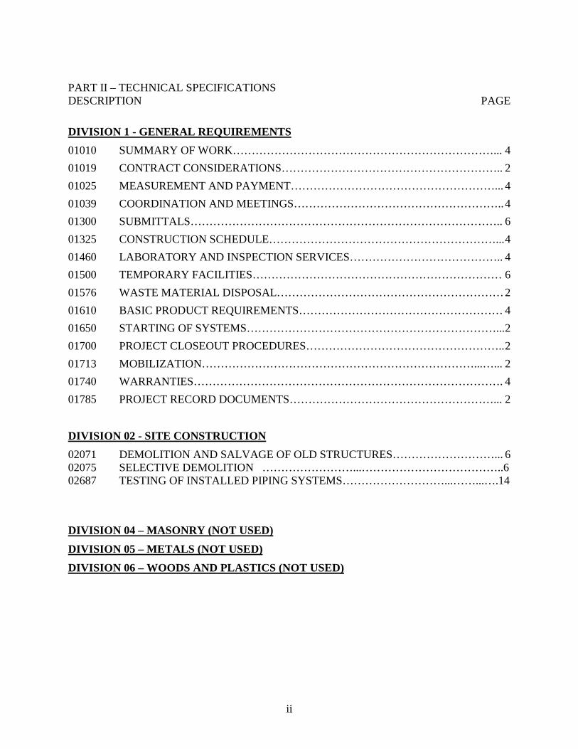
DIVISION 1 - GENERAL REQUIREMENTS 01010 SUMMARY OF WORK……………………………………………………………... 4 01019 CONTRACT CONSIDERATIONS………………………………………………….. 2 01025 MEASUREMENT AND PAYMENT………………………………………………... 4 01039 COORDINATION AND MEETINGS……………………………………………….. 4 01300 SUBMITTALS……………………………………………………………………….. 6 01325 CONSTRUCTION SCHEDULE……………………………………………………... 4 01460 LABORATORY AND INSPECTION SERVICES………………………………….. 4 01500 TEMPORARY FACILITIES………………………………………………………… 6 01576 WASTE MATERIAL DISPOSAL…………………………………………………… 2 01610 BASIC PRODUCT REQUIREMENTS……………………………………………… 4 01650 STARTING OF SYSTEMS…………………………………………………………... 2 01700 PROJECT CLOSEOUT PROCEDURES…………………………………………….. 2 01713 MOBILIZATION………………………………………………………………...…... 2 01740 WARRANTIES………………………………………………………………………. 4 01785 PROJECT RECORD DOCUMENTS………………………………………………... 2 DIVISION 02 - SITE CONSTRUCTION 02071 DEMOLITION AND SALVAGE OF OLD STRUCTURES………………………... 6 02075 SELECTIVE DEMOLITION ……………………...………………………………..6 02687 TESTING OF INSTALLED PIPING SYSTEMS………………………...……...….14 DIVISION 04 – MASONRY (NOT USED) DIVISION 05 – METALS (NOT USED) DIVISION 06 – WOODS AND PLASTICS (NOT USED)
iii
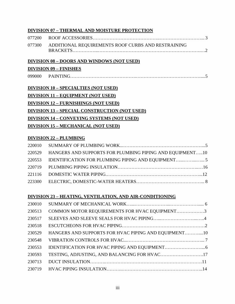
DIVISION 07 – THERMAL AND MOISTURE PROTECTION 077200 ROOF ACCESSORIES……………………………………..………………………... 3 077300 ADDITIONAL REQUIREMENTS ROOF CURBS AND RESTRAINING BRACKETS……………..………………………………………………………….…2 DIVISION 08 – DOORS AND WINDOWS (NOT USED) DIVISION 09 – FINISHES 099000 PAINTING…………………………………….…………………………………….... 5 DIVISION 10 – SPECIALTIES (NOT USED) DIVISION 11 – EQUIPMENT (NOT USED) DIVISION 12 – FURNISHINGS (NOT USED) DIVISION 13 – SPECIAL CONSTRUCTION (NOT USED) DIVISION 14 – CONVEYING SYSTEMS (NOT USED) DIVISION 15 – MECHANICAL (NOT USED) DIVISION 22 – PLUMBING 220010 SUMMARY OF PLUMBING WORK...……………………………………………... 5 220529 HANGERS AND SUPPORTS FOR PLUMBING PIPING AND EQUIPMENT…..10 220553 IDENTIFICATION FOR PLUMBING PIPING AND EQUIPMENT…...……...…... 5 220719 PLUMBING PIPING INSULATION……………………………………………..…16 221116 DOMESTIC WATER PIPING.……………………………………………………...12 223300 ELECTRIC, DOMESTIC-WATER HEATERS……………………………………... 8
DIVISION 23 – HEATING, VENTILATION, AND AIR-CONDITIONING 230010 SUMMARY OF MECHANICAL WORK…...…………………...………………..... 6 230513 COMMON MOTOR REQUIREMENTS FOR HVAC EQUIPMENT………………3 230517 SLEEVES AND SLEEVE SEALS FOR HVAC PIPING…...…………………...…..4 230518 ESCUTCHEONS FOR HVAC PIPING………………………………………………2 230529 HANGERS AND SUPPORTS FOR HVAC PIPING AND EQUIPMENT………....10 230548 VIBRATION CONTROLS FOR HVAC...…………………………………………... 7 230553 IDENTIFICATION FOR HVAC PIPING AND EQUIPMENT……………………... 6 230593 TESTING, ADJUSTING, AND BALANCING FOR HVAC……………………….17 230713 DUCT INSULATION……….………………………………………………………11 230719 HVAC PIPING INSULATION……….……………………………………………..14
iv
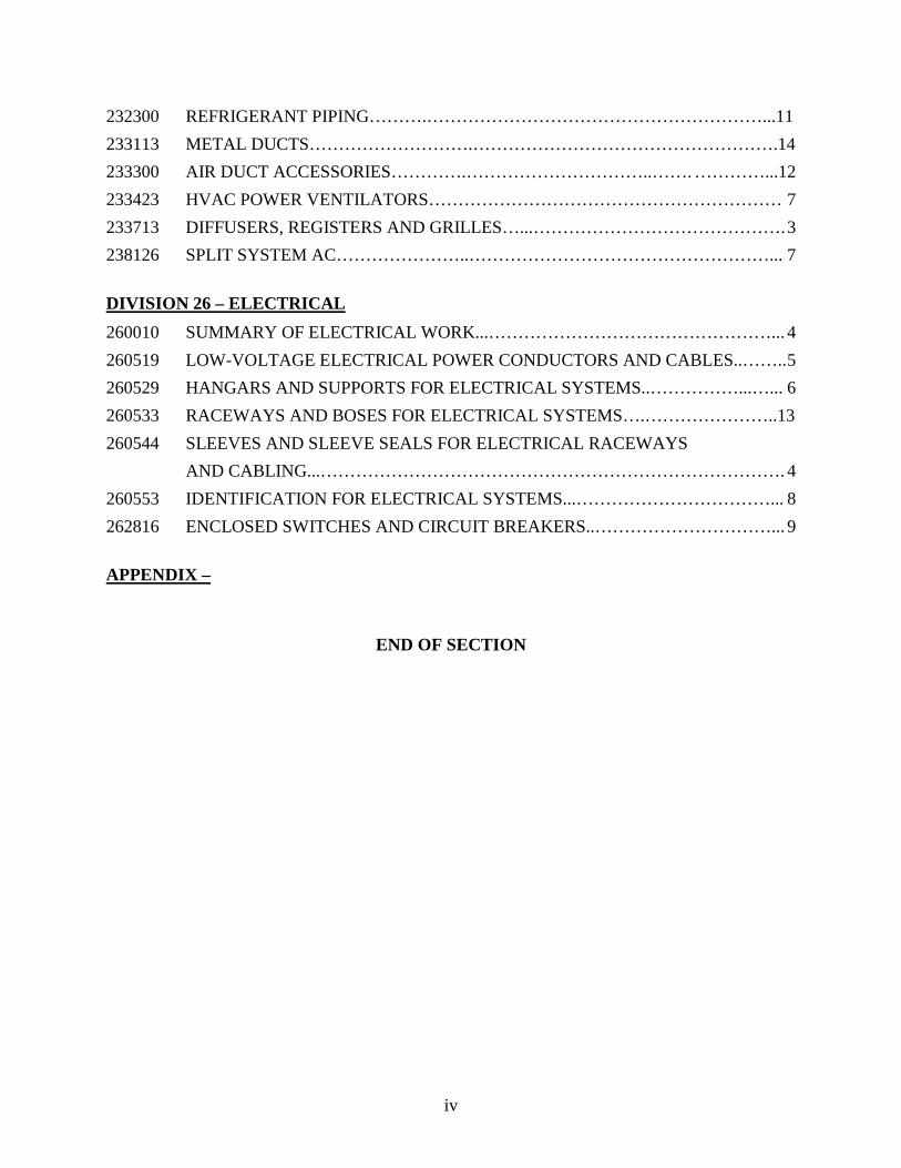
232300 REFRIGERANT PIPING……….…………………………………………………...11 233113 METAL DUCTS……………………….…………………………………………….14 233300 AIR DUCT ACCESSORIES………….…………………………..……. …………...12 233423 HVAC POWER VENTILATORS…………………………………………………… 7 233713 DIFFUSERS, REGISTERS AND GRILLES…...……………………………………. 3 238126 SPLIT SYSTEM AC…………………..……………………………………………... 7 DIVISION 26 – ELECTRICAL 260010 SUMMARY OF ELECTRICAL WORK...…………………………………………... 4 260519 LOW-VOLTAGE ELECTRICAL POWER CONDUCTORS AND CABLES..…….. 5 260529 HANGARS AND SUPPORTS FOR ELECTRICAL SYSTEMS..……………...…... 6 260533 RACEWAYS AND BOSES FOR ELECTRICAL SYSTEMS….…………………..13 260544 SLEEVES AND SLEEVE SEALS FOR ELECTRICAL RACEWAYS AND CABLING...……………………………………………………………………. 4 260553 IDENTIFICATION FOR ELECTRICAL SYSTEMS...……………………………... 8 262816 ENCLOSED SWITCHES AND CIRCUIT BREAKERS..…………………………... 9 APPENDIX –
END OF SECTION
Brownsville Public Utilities Board 1
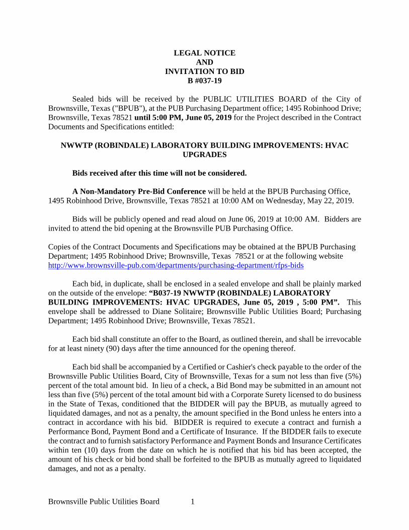
LEGAL NOTICE AND
INVITATION TO BID B #037-19
Sealed bids will be received by the PUBLIC UTILITIES BOARD of the City of
Brownsville, Texas ("BPUB"), at the PUB Purchasing Department office; 1495 Robinhood Drive; Brownsville, Texas 78521 until 5:00 PM, June 05, 2019 for the Project described in the Contract Documents and Specifications entitled:
NWWTP (ROBINDALE) LABORATORY BUILDING IMPROVEMENTS: HVAC UPGRADES
Bids received after this time will not be considered.
A Non-Mandatory Pre-Bid Conference will be held at the BPUB Purchasing Office, 1495 Robinhood Drive, Brownsville, Texas 78521 at 10:00 AM on Wednesday, May 22, 2019.
Bids will be publicly opened and read aloud on June 06, 2019 at 10:00 AM. Bidders are invited to attend the bid opening at the Brownsville PUB Purchasing Office. Copies of the Contract Documents and Specifications may be obtained at the BPUB Purchasing Department; 1495 Robinhood Drive; Brownsville, Texas 78521 or at the following website http://www.brownsville-pub.com/departments/purchasing-department/rfps-bids Each bid, in duplicate, shall be enclosed in a sealed envelope and shall be plainly marked on the outside of the envelope: “B037-19 NWWTP (ROBINDALE) LABORATORY BUILDING IMPROVEMENTS: HVAC UPGRADES, June 05, 2019 , 5:00 PM”. This envelope shall be addressed to Diane Solitaire; Brownsville Public Utilities Board; Purchasing Department; 1495 Robinhood Drive; Brownsville, Texas 78521.
Each bid shall constitute an offer to the Board, as outlined therein, and shall be irrevocable for at least ninety (90) days after the time announced for the opening thereof.
Each bid shall be accompanied by a Certified or Cashier's check payable to the order of the
Brownsville Public Utilities Board, City of Brownsville, Texas for a sum not less than five (5%) percent of the total amount bid. In lieu of a check, a Bid Bond may be submitted in an amount not less than five (5%) percent of the total amount bid with a Corporate Surety licensed to do business in the State of Texas, conditioned that the BIDDER will pay the BPUB, as mutually agreed to liquidated damages, and not as a penalty, the amount specified in the Bond unless he enters into a contract in accordance with his bid. BIDDER is required to execute a contract and furnish a Performance Bond, Payment Bond and a Certificate of Insurance. If the BIDDER fails to execute the contract and to furnish satisfactory Performance and Payment Bonds and Insurance Certificates within ten (10) days from the date on which he is notified that his bid has been accepted, the amount of his check or bid bond shall be forfeited to the BPUB as mutually agreed to liquidated damages, and not as a penalty.
Brownsville Public Utilities Board 2
The BPUB will not be responsible in the event that the U.S. Postal Service or any other
courier system fails to deliver the sealed bids to the Brownsville Public Utilities Board, Purchasing Office by the given deadline above. No bids will be accepted via facsimile or electronic transmission.
The BPUB specifically reserves the right to reject any or all bids, to waive irregularities or informalities in any or all bids and to accept any bid which is deemed to be in the best interest of the Board. Diane Solitaire Purchasing Department (956) 983-6366 (956) 983-6367-Fax
Brownsville Public Utilities Board 3
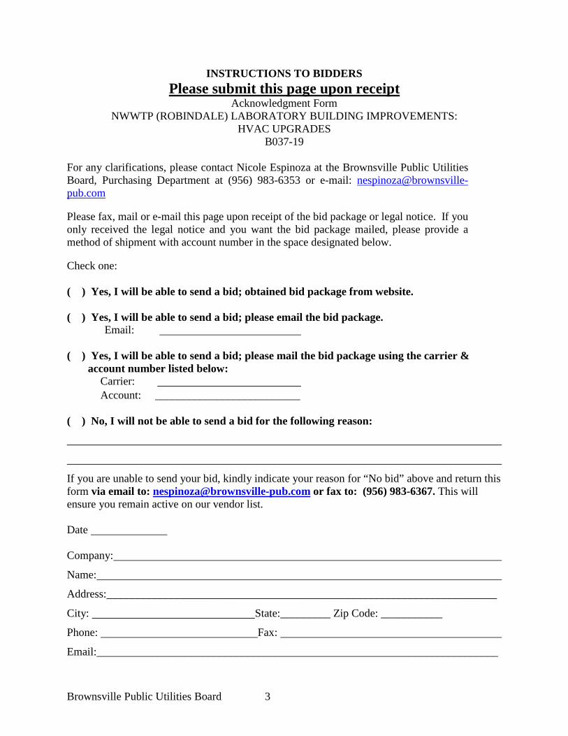
INSTRUCTIONS TO BIDDERS Please submit this page upon receipt
Acknowledgment Form NWWTP (ROBINDALE) LABORATORY BUILDING IMPROVEMENTS:
HVAC UPGRADES B037-19
For any clarifications, please contact Nicole Espinoza at the Brownsville Public Utilities Board, Purchasing Department at (956) 983-6353 or e-mail: [email protected] Please fax, mail or e-mail this page upon receipt of the bid package or legal notice. If you only received the legal notice and you want the bid package mailed, please provide a method of shipment with account number in the space designated below. Check one: ( ) Yes, I will be able to send a bid; obtained bid package from website. ( ) Yes, I will be able to send a bid; please email the bid package. Email: ( ) Yes, I will be able to send a bid; please mail the bid package using the carrier &
account number listed below: Carrier:
Account: __________________________ ( ) No, I will not be able to send a bid for the following reason:
If you are unable to send your bid, kindly indicate your reason for “No bid” above and return this form via email to: [email protected] or fax to: (956) 983-6367. This will ensure you remain active on our vendor list. Date Company:
Name:
Address:______________________________________________________________________
City: State:_________ Zip Code: ___________
Phone: Fax:
Email:________________________________________________________________________
Brownsville Public Utilities Board 4
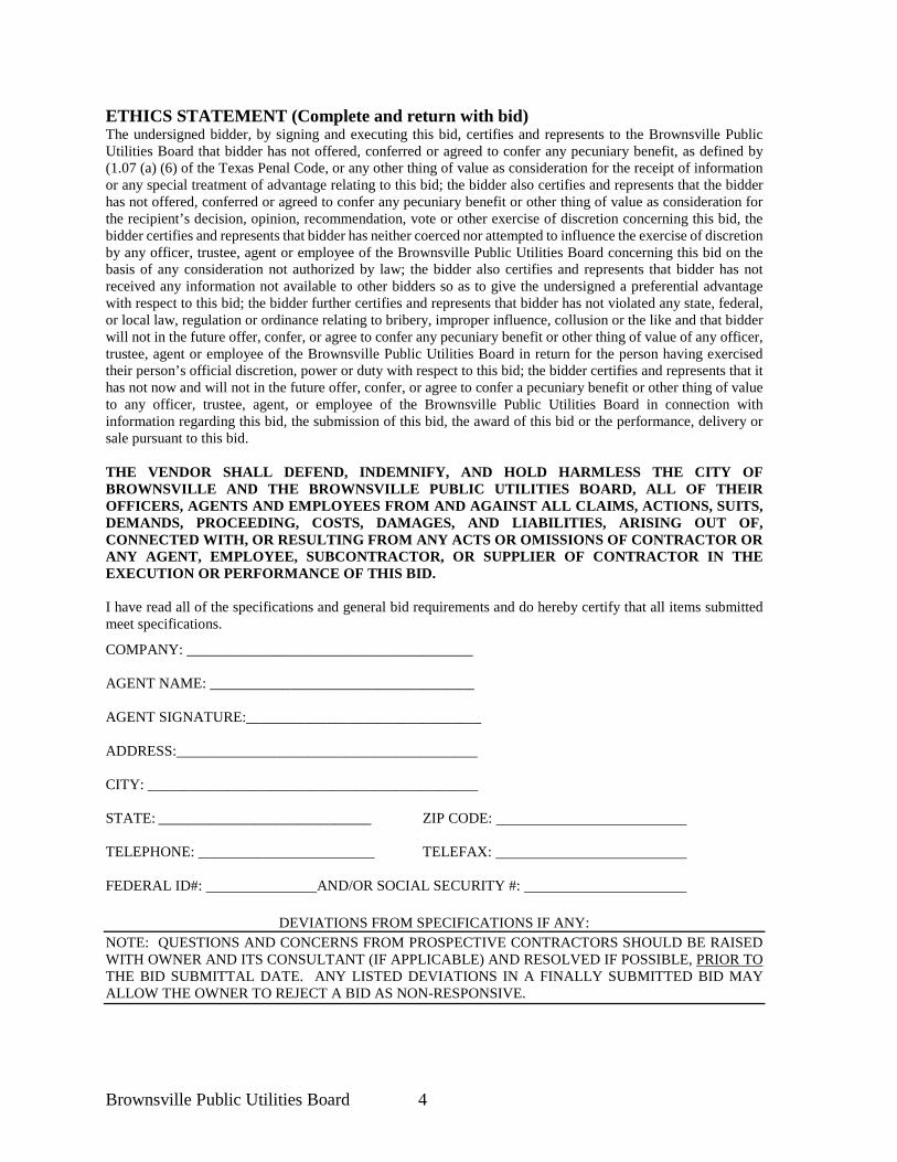
ETHICS STATEMENT (Complete and return with bid) The undersigned bidder, by signing and executing this bid, certifies and represents to the Brownsville Public Utilities Board that bidder has not offered, conferred or agreed to confer any pecuniary benefit, as defined by (1.07 (a) (6) of the Texas Penal Code, or any other thing of value as consideration for the receipt of information or any special treatment of advantage relating to this bid; the bidder also certifies and represents that the bidder has not offered, conferred or agreed to confer any pecuniary benefit or other thing of value as consideration for the recipient’s decision, opinion, recommendation, vote or other exercise of discretion concerning this bid, the bidder certifies and represents that bidder has neither coerced nor attempted to influence the exercise of discretion by any officer, trustee, agent or employee of the Brownsville Public Utilities Board concerning this bid on the basis of any consideration not authorized by law; the bidder also certifies and represents that bidder has not received any information not available to other bidders so as to give the undersigned a preferential advantage with respect to this bid; the bidder further certifies and represents that bidder has not violated any state, federal, or local law, regulation or ordinance relating to bribery, improper influence, collusion or the like and that bidder will not in the future offer, confer, or agree to confer any pecuniary benefit or other thing of value of any officer, trustee, agent or employee of the Brownsville Public Utilities Board in return for the person having exercised their person’s official discretion, power or duty with respect to this bid; the bidder certifies and represents that it has not now and will not in the future offer, confer, or agree to confer a pecuniary benefit or other thing of value to any officer, trustee, agent, or employee of the Brownsville Public Utilities Board in connection with information regarding this bid, the submission of this bid, the award of this bid or the performance, delivery or sale pursuant to this bid. THE VENDOR SHALL DEFEND, INDEMNIFY, AND HOLD HARMLESS THE CITY OF BROWNSVILLE AND THE BROWNSVILLE PUBLIC UTILITIES BOARD, ALL OF THEIR OFFICERS, AGENTS AND EMPLOYEES FROM AND AGAINST ALL CLAIMS, ACTIONS, SUITS, DEMANDS, PROCEEDING, COSTS, DAMAGES, AND LIABILITIES, ARISING OUT OF, CONNECTED WITH, OR RESULTING FROM ANY ACTS OR OMISSIONS OF CONTRACTOR OR ANY AGENT, EMPLOYEE, SUBCONTRACTOR, OR SUPPLIER OF CONTRACTOR IN THE EXECUTION OR PERFORMANCE OF THIS BID. I have read all of the specifications and general bid requirements and do hereby certify that all items submitted meet specifications.
COMPANY: _______________________________________ AGENT NAME: ____________________________________ AGENT SIGNATURE:________________________________ ADDRESS:_________________________________________ CITY: _____________________________________________ STATE: _____________________________ ZIP CODE: TELEPHONE: ________________________ TELEFAX: FEDERAL ID#: AND/OR SOCIAL SECURITY #:
DEVIATIONS FROM SPECIFICATIONS IF ANY:
NOTE: QUESTIONS AND CONCERNS FROM PROSPECTIVE CONTRACTORS SHOULD BE RAISED WITH OWNER AND ITS CONSULTANT (IF APPLICABLE) AND RESOLVED IF POSSIBLE, PRIOR TO THE BID SUBMITTAL DATE. ANY LISTED DEVIATIONS IN A FINALLY SUBMITTED BID MAY ALLOW THE OWNER TO REJECT A BID AS NON-RESPONSIVE.
Brownsville Public Utilities Board 5
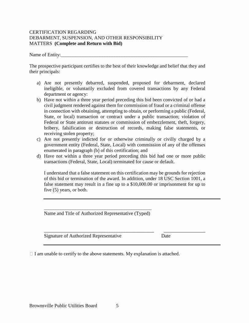
CERTIFICATION REGARDING DEBARMENT, SUSPENSION, AND OTHER RESPONSIBILITY MATTERS (Complete and Return with Bid) Name of Entity:____________________________________________________ The prospective participant certifies to the best of their knowledge and belief that they and their principals:
a) Are not presently debarred, suspended, proposed for debarment, declared ineligible, or voluntarily excluded from covered transactions by any Federal department or agency:
b) Have not within a three year period preceding this bid been convicted of or had a civil judgment rendered against them for commission of fraud or a criminal offense in connection with obtaining, attempting to obtain, or performing a public (Federal, State, or local) transaction or contract under a public transaction; violation of Federal or State antitrust statutes or commission of embezzlement, theft, forgery, bribery, falsification or destruction of records, making false statements, or receiving stolen property;
c) Are not presently indicted for or otherwise criminally or civilly charged by a government entity (Federal, State, Local) with commission of any of the offenses enumerated in paragraph (b) of this certification; and
d) Have not within a three year period preceding this bid had one or more public transactions (Federal, State, Local) terminated for cause or default. I understand that a false statement on this certification may be grounds for rejection of this bid or termination of the award. In addition, under 18 USC Section 1001, a false statement may result in a fine up to a $10,000.00 or imprisonment for up to five (5) years, or both. ____________________________________________ Name and Title of Authorized Representative (Typed) _____________________________________________ _________________ Signature of Authorized Representative Date
I am unable to certify to the above statements. My explanation is attached.
Brownsville Public Utilities Board 6
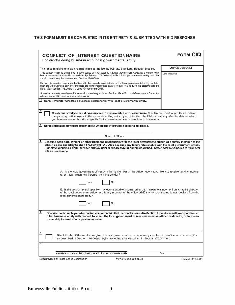
THIS FORM MUST BE COMPLETED IN ITS ENTIRETY & SUBMITTED WITH BID RESPONSE
Brownsville Public Utilities Board 7
Brownsville Public Utilities Board 8
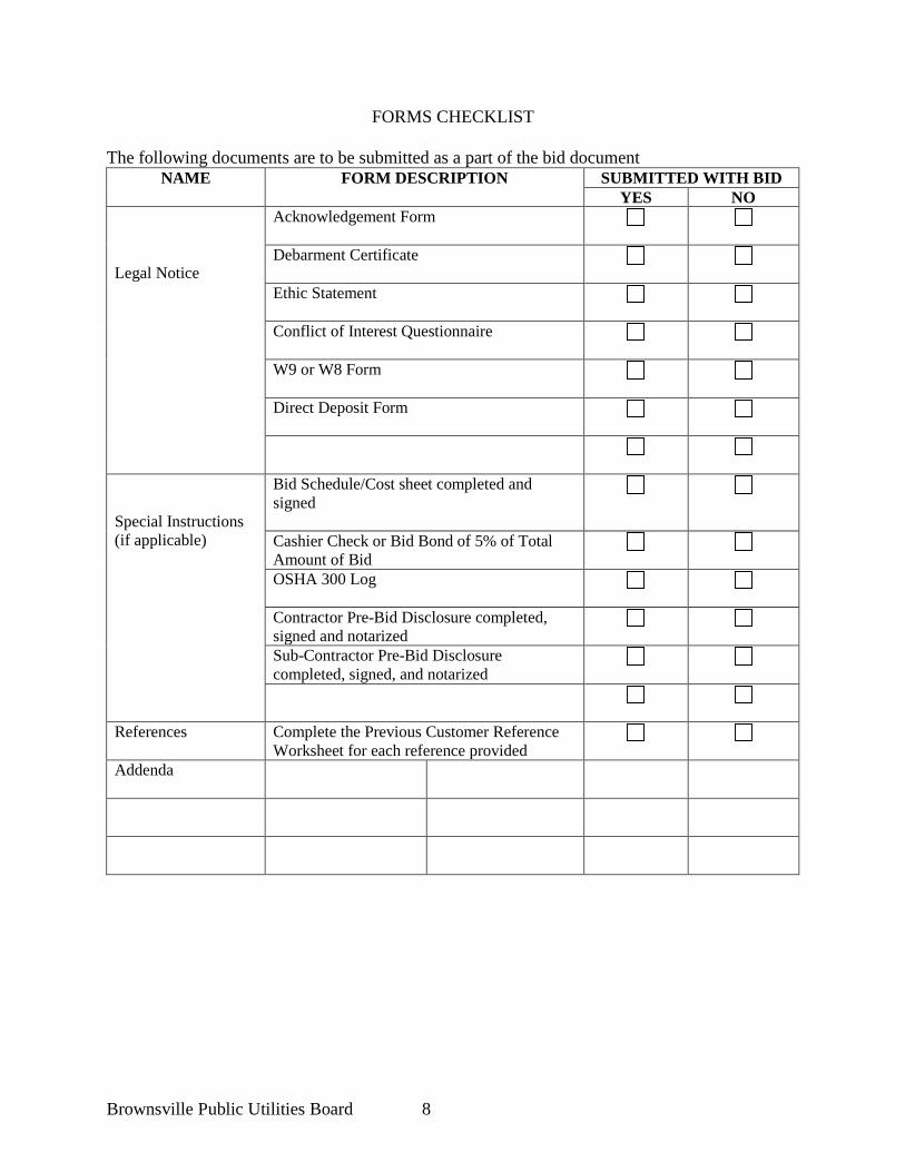
FORMS CHECKLIST The following documents are to be submitted as a part of the bid document
NAME FORM DESCRIPTION SUBMITTED WITH BID YES NO
Legal Notice
Acknowledgement Form
Debarment Certificate
Ethic Statement
Conflict of Interest Questionnaire
W9 or W8 Form
Direct Deposit Form
Special Instructions (if applicable)
Bid Schedule/Cost sheet completed and signed
Cashier Check or Bid Bond of 5% of Total Amount of Bid
OSHA 300 Log
Contractor Pre-Bid Disclosure completed, signed and notarized
Sub-Contractor Pre-Bid Disclosure completed, signed, and notarized
References Complete the Previous Customer Reference Worksheet for each reference provided
Addenda
Brownsville Public Utilities Board 9
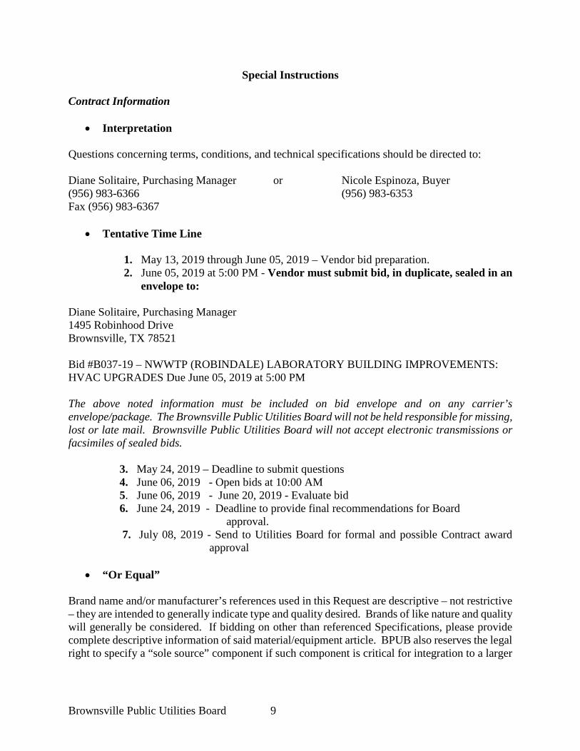
Special Instructions
Contract Information
• Interpretation Questions concerning terms, conditions, and technical specifications should be directed to: Diane Solitaire, Purchasing Manager or Nicole Espinoza, Buyer (956) 983-6366 (956) 983-6353 Fax (956) 983-6367
• Tentative Time Line
1. May 13, 2019 through June 05, 2019 – Vendor bid preparation. 2. June 05, 2019 at 5:00 PM - Vendor must submit bid, in duplicate, sealed in an
envelope to: Diane Solitaire, Purchasing Manager 1495 Robinhood Drive Brownsville, TX 78521 Bid #B037-19 – NWWTP (ROBINDALE) LABORATORY BUILDING IMPROVEMENTS: HVAC UPGRADES Due June 05, 2019 at 5:00 PM The above noted information must be included on bid envelope and on any carrier’s envelope/package. The Brownsville Public Utilities Board will not be held responsible for missing, lost or late mail. Brownsville Public Utilities Board will not accept electronic transmissions or facsimiles of sealed bids. 3. May 24, 2019 – Deadline to submit questions
4. June 06, 2019 - Open bids at 10:00 AM 5. June 06, 2019 - June 20, 2019 - Evaluate bid
6. June 24, 2019 - Deadline to provide final recommendations for Board approval.
7. July 08, 2019 - Send to Utilities Board for formal and possible Contract award approval
• “Or Equal”
Brand name and/or manufacturer’s references used in this Request are descriptive – not restrictive – they are intended to generally indicate type and quality desired. Brands of like nature and quality will generally be considered. If bidding on other than referenced Specifications, please provide complete descriptive information of said material/equipment article. BPUB also reserves the legal right to specify a “sole source” component if such component is critical for integration to a larger
Brownsville Public Utilities Board 10
assembly and alternative manufactured items will not meet the design and/or performance needs of the BPUB, in BPUB’s sole discretion.
• Pricing Bid unit prices on BPUB estimated quantities specified, extend and show total. In case of errors in extension, unit prices expressed in written words and not numerals, shall govern. Prices shall remain firm throughout the Contract. All fields (UNIT PRICE & TOTAL PRICE) in the Bid Schedule must be filled in. The data must be complete to identify any bidding brand called for specifically. Failure to submit any of the above information with the sealed bid may disqualify bid as non-responsive.
• Contractor Representative The successful contractor agrees to send a personal representative with binding authority for the company to the Brownsville Public Utilities Board, upon request, to make any minor clarifications or adjustments and/or assist with coordination of all transactions as needed to allow Contract entry.
• Quality of Products All material and equipment items specified must be new, in first class condition, including containers suitable for shipment and storage. No substitutions in standard grades or lesser quality will be accepted.
• Determining Factors for Award
1. Price 2. Responsibility of contractor to perform the intended work and responsiveness to
the bid request. 3. Compliance with requirements of the technical specifications 4. Quality of performance on previous work on similar contracts 5. Recent successful completion of similar projects 6. BPUB financial and legal responsibility evaluations of any identified teaming
arrangements involving significant joint ventures, subcontractors, and suppliers. 7. Safety record will be considered when determining the responsibility of the bidder
• Contract with Vendor/Entity Indebted to BPUB
It is a policy of the BPUB to refuse to enter into a contract or other transaction with an individual, sole proprietorship, joint venture, Limited Liability Company or other entity indebted to BPUB.
• Vendor ACH (Direct Deposit) Services
The BPUB has implemented a payment service for vendors/contractors by depositing the contract payment directly to the contractor’s/vendor’s bank account. Successful vendor(s)/contractors will
Brownsville Public Utilities Board 11
be required to receive payments directly through Automated Clearing House (ACH) in lieu of a paper check. Return the Direct Deposit Authorization Form with the bid response. The awarded vendor must agree to receive payments via ACH (Direct Deposit).
• Tax Identification Number (TIN) In accordance with IRS Publication 1220, aW9 form, or a W8 form in cases of a foreign vendor, will be required of all vendors doing business with the Brownsville PUB. If a W9 or W8 form is not made available to Brownsville PUB, the first payment will be subject to income tax withholding at a rate of 28% or 30% depending on the U.S. status and the source of income as per IRS Publication 1220. The W9 or W8 form must be included with bid response. Attached are sample forms.
• Taxes The City of Brownsville and its Brownsville Public Utilities Board are exempt from Federal Excise Tax, State Tax and local sales Taxes. Do not include any taxes in the bid proposal. If it is later determined that tax was included in the bid it will not be included in the tabulation or any awards. Tax exemption certificates will be furnished by BPUB upon request.
• Signing of Bid Failure to manually sign bid will disqualify it. Person signing bid should show title or authority to bind their firm to a contract.
• EEOC Guidelines During the performance of this contract, the contractor agrees not to discriminate against any employee or applicant for employment because of race, national origin, age, religion, gender, sexual preference, marital or veteran status, or physically challenging condition.
• Living Wage Statement On April 16, 2007, the BPUB Board of Directors approved a local “living wage” policy that requires all Contractors and Subcontractors performing 100% Non-Federally funded Work for the BPUB to pay a minimum wage rate of $8.00/hour. The BPUB requires that all Contractors and Subcontractors comply with this policy. Otherwise, the BPUB adopts the Federal Department of Labor Wage scales for Cameron County on 100% Non-Federally funded projects as specified later herein in the Supplementary General Conditions.
• Contract and Purchase Order
The services shall be completed in a timely manner as specified in specifications. A contract for the services will be placed into effect by means of a purchase order issued by the Brownsville Public Utilities Board after tabulation and final Contract approval by the Board.
Brownsville Public Utilities Board 12
• Brownsville Public Utilities Board Rights
1. If only one or no bid is received by "submission date", the BPUB has the right to
reject, re-bid, accept and/or extend the bid by up to an additional two (2) weeks from original submission date.
2. The right to reject any/or all bids and to make award as it may appear to be advantageous to the Brownsville Public Utilities Board.
3. The right to hold bid for 90 days from submission date without action, and to waive all informalities in any bid.
4. The right to extend the total bid beyond the original 90-day period prior to an award, if agreed upon in writing by all parties (BPUB and vendor/contractor) and if bidder/vendor holds original bid prices firm.
5. The right to terminate for cause or convenience all or any part of the unfinished portion of the Project resulting from this solicitation within Thirty (30) calendar days written notice; for cause: upon default by the vendor/contractor, for delay or non-performance by the vendor/contractor; or if it is deemed in the best interest of the BPUB for BPUB’s convenience.
• Corrections
Any interpretation, correction, or change of the Invitation to Bid will be made by written ADDENDUM. Changes or corrections will be issued by the Brownsville PUB Purchasing Department. Addenda will be faxed to all who have returned the bid acknowledgment form. Addenda will be issued as expeditiously as possible. It is the responsibility of the vendors/contractors to determine whether all Addenda have been received. It will be the responsibility of all respondents to contact the Brownsville PUB prior to submitting a response to the Invitation to Bid to ascertain if any/all Addenda have been issued, and to obtain any all Addenda, execute them, and return Addenda with the response to the Invitation to Bid. Addenda may also be posted on BPUB’s website. 1. RECEIPT AND OPENING OF BIDS: The Brownsville Public Utilities Board, City of Brownsville, Texas (hereinafter called OWNER), invites bids on the form attached hereto, all blanks of which must be appropriately filled in, in ink, for Project entitled “NWWTP (ROBINDALE) LABORATORY BUILDING IMPROVEMENTS: HVAC UPGRADES”. The OWNER may consider informal and non-responsive, any bid not prepared and submitted in accordance with the provisions hereof and may waive any informalities or reject any and all bids. Any bid may be withdrawn by vendor/contractor prior to the above scheduled time for the opening of bids or OWNER authorized postponement thereof. Any bid received after the time and date specified shall not be considered. No BIDDER may withdraw a bid within at least ninety (90) days after the actual date of the opening thereof.
Brownsville Public Utilities Board 13
2. INSPECTION OF SITE: Each BIDDER shall visit the Project site of the proposed work and fully acquaint himself with the existing conditions there relating to construction and labor, and shall fully inform himself as to the facility involved, the difficulties and restrictions attending the performance of the Contract. The BIDDER shall thoroughly examine and familiarize himself with the Drawings, Technical Specifications, and all other Contract Documents. The Contractor, by the execution of the Contract, shall in no way be relieved of any obligation under it due to his failure to receive or examine any form or legal instrument, or to visit the Project site and acquaint himself with the conditions there existing and the OWNER will be justified in rejecting any claim for extra time, or compensation, or both, based on facts regarding which Contractor should have been on notice as a result of such a diligent Project site visitation. Visits to the Project site shall be arranged by calling Robert Castillo with the Robindale Wastewater Treatment Plant at telephone no. (956) 983-6552. 3. PREPARATION OF BID AND USE OF SEPARATE BID FORMS: These Contract Documents include a complete set of bidding documents. The BIDDER shall copy all Documents listed in the table of contents under the heading BIDDING DOCUMENTS and shall submit two sets (original signed and one signed photocopy) of his bid on these forms. A bid shall be comprised of the BIDDING DOCUMENTS completed by the BIDDER plus supplemental information required by the Specifications and Contract Documents. If any of the information submitted as part of the bid is considered to be proprietary by the BIDDER, he shall conspicuously identify such intended confidential information in his bid. BPUB is subject to the provisions of the Texas Public Information Act and cannot legally guarantee confidentiality of submittals and may need to consult with its legal counsel and the Texas Attorney General in rendering decisions on any requested disclosures.
a) Preparation. Each bid shall be carefully prepared using the bid and bid data forms included as a part of the bidding documents. Entries on the bid and bid data forms shall be typed, using dark black ribbon, or legibly written in black ink. All prices shall be stated in written words and numeric figures, except where the forms provide for figures only. In case of discrepancy, especially in any sum total extensions, the amount shown in written words will generally prevail over numeric unit prices.
The BIDDER shall acknowledge, in the space provided in the bid form, receipt of each Addendum issued for the Specifications and Documents during the bidding period.
The BIDDER shall assemble all drawings, catalog data, and other supplementary information necessary to thoroughly describe work, materials and equipment covered by the bid, and shall attach such supplemental information to the copies of the specifications and documents submitted.
Brownsville Public Utilities Board 14
b) Signatures. Each BIDDER shall sign the bid with his usual signature and shall give his full business address. The BIDDER's name stated on the bid shall be the exact legal name of the firm. The names of all persons signing should also be typed or printed below the signature.
Bids by partnerships shall be signed with the partnership name followed by the signature and designation of one of the partners or other authorized representative. A complete list of the partners shall be included with the bid.
Bids by a corporation shall be signed in the official corporate name of the corporation, followed by the signature and designation of the “president,” “secretary,” or other appropriate person authorized to bind the corporation.
A bid by a person who affixes to his signature the word "president," "secretary," "agent," or other designation, without disclosing his principal, will be rejected. Satisfactory evidence of the authority of the officer signing on behalf of the corporation shall be furnished. Bidding corporations shall designate the state in which they are incorporated and the address of their principal office.
c) Submittal. The original signed bid (and its accompanying photocopy) shall be transmitted to arrive at the designated BPUB address not later than the date and time stipulated in the Legal Notice and Invitation to Bid.
Submit the original signed bid (and its accompanying photocopy) to:
Brownsville Public Utilities Board of the
City of Brownsville, Texas 1495 Robinhood Drive
Brownsville, Texas 78521
Attention: Ms. Diane Solitaire Purchasing Department
Each bid must be submitted in duplicate as stated above (original signature and photocopy), in a sealed envelope bearing on the outside the name of the BIDDER, his address, and the name of the Project for which the bid is submitted. If forwarded by mail, the sealed envelope containing the bid itself must be enclosed in another mailing envelope addressed as specified in the bid form. 4. METHOD OF BIDDING: UNIT PRICE, AND LUMP SUM. Prices shall be firm, not subject to qualification, condition or adjustment. Prices shall be in United States dollars. Prices shall be lump sum, except where unit prices are requested by the bid forms. When unit price items are required by the bid, the unit prices for each of the several items in the bid of each BIDDER shall include its pro-rata share of overhead, so that the sum of the products obtained by multiplying the quantity shown for each item, by the unit price bid, represents the total bid. Any bid not conforming to that requirement may be rejected as informal and non-responsive.
Brownsville Public Utilities Board 15
The special attention of all BIDDERS is called to this provision, for should conditions make it necessary to revise the quantities, no limit will be fixed for such increased or decreased quantities nor extra compensation allowed, provided the net monetary value of all such additive and subtractive changes in quantities of such items of work pursuant to public competitive bidding statutes (i.e., difference in cost) shall not cumulatively increase or decrease the original Contract price by more than twenty-five (25%) percent. A proposed decrease only that exceeds twenty-five (25%) percent of the original Contract price must be agreed to in advance by the Contractor. 5. DISCLOSURE BY BIDDER: Each BIDDER shall submit with the bid documents, on the form furnished for that purpose, his Pre-Bid Disclosure Statement showing his experience record in performing the type of work embraced in the contract, his organization and equipment available for the work contemplated, and, when specifically requested by the OWNER, a detailed financial statement. The OWNER shall have the right to take such steps as it deems necessary, including telephonic contact to other owner references, to determine the ability and responsibility of the BIDDER to perform his obligations under the Contract and the BIDDER shall be responsive in furnishing the OWNER all such information and data for this purpose as it may request. OWNER reserves the right to reject any bid where an investigation of the available evidence or information does not satisfy the OWNER that the BIDDER is responsible to properly carry out the terms of the Contract. This shall also apply to any proposed subcontractor(s). 6. SUBCONTRACTS: The BIDDER is specifically advised that any person, firm, or other party to whom it is proposed to award a subcontract under this contract must be acceptable to the OWNER, and that a Pre-Bid Disclosure Statement for each proposed subcontractor must also be submitted with the bid documents. 7. BID SECURITY: Each bid must be accompanied by a certified or cashier's check, or a bid bond prepared on the form of the bid bond attached hereto, duly executed by the BIDDER as principal, and having as surety therein a surety company approved by the OWNER, and authorized to do business in the State of Texas, in the amount of not less than five (5%) percent of the total bid amount, but not less than $2,500.00. Such checks, or bid bonds will be returned to all except the three lowest BIDDERS within fifteen (15) days after the opening of bids, and the remaining checks, or bid bonds will be returned promptly after the OWNER and the accepted successful BIDDER have executed the Contract or if no award has been made, within Ninety (90) calendar days after the date of the opening of bids. The bid security will be returned upon demand of the BIDDER at any time thereafter, so long as he has not been notified of the acceptance of his bid. 8. ADDENDA AND INTERPRETATIONS: No oral interpretations by OWNER and its representatives shall be binding upon OWNER as to the meaning of the Plans, Specifications, Contract Documents, or other pre-bid documents.
Brownsville Public Utilities Board 16
Any interpretation, correction, or change of the bid documents will be made by ADDENDUM only. Changes or corrections will only be issued by the Brownsville PUB Purchasing Department. Addenda will be faxed to all who have returned the bid acknowledgment form. Addenda will be issued as expeditiously as possible. It is the responsibility of the vendors/contractors to determine whether all Addenda have been received. It will be the responsibility of all respondents to contact the Brownsville PUB Purchasing Department prior to submitting a response to the bid to ascertain if any Addenda have been issued, and to obtain any all Addenda, execute them, and return Addenda with the response to the bid. All Addenda so issued shall become part of the Contract Documents. Addenda may also be posted on BPUB’s website. 9. FACSIMILE MODIFICATION: Any BIDDER may modify (not originally submit) his bid by facsimile communication at any time prior to the scheduled bid closing time for receipt of bids, provided such communication is received by the OWNER, in the BPUB Purchasing Department, prior to the bid closing time, and provided further, the OWNER is satisfied that a written confirmation of the facsimile modification, over the original signature of the BIDDER, was also mailed prior to the bid closing time. The facsimile communication should not reveal the total bid price, but only should provide the clarification, addition or subtraction, or other modification, so that the final bid prices or terms intended will not be known by the OWNER, until the original sealed bid is opened and the modification computed by OWNER. Revised bids submitted before the opening of bids, whether forwarded by mail or facsimile, if representing an increase in excess of two percent (2%) of the original bid submittal, must have the bid security (bid bond or check) adjusted accordingly; otherwise the bid will not be considered responsive. If the written and originally signed confirmation of a bid revision is not received within three (3) calendar days after the bid closing time, no consideration will be given to any proposed adjustment contained in the facsimile modification. 10. TIME FOR RECEIVING BIDS: Bids received prior to the advertised hour of opening will be securely kept sealed by BPUB. The officer whose duty it is to open them will decide when the specified time has arrived, and no bid received thereafter will be considered; except that when a bid arrives by mail after the time fixed for opening, but before the public reading of all other bids is completed, and it is shown to the satisfaction of the OWNER that the non-arrival on time was due solely to delay in the mails for which the BIDDER was not responsible, such bid will be received and considered. BIDDERS are cautioned that, while facsimile modifications of bids may be received as provided above, such modifications, if not explicit and if in any sense subject to misinterpretation, shall make the bid so modified or amended, subject to rejection for non-responsiveness. 11. OPENING OF BIDS:
Brownsville Public Utilities Board 17
At the time and place fixed for the public opening of bids, the OWNER will cause to be opened and publicly read aloud every bid received within the time set for receiving bids, irrespective of any irregularities therein. BIDDERS and other persons properly interested may be present, in person or by representative. 12. WITHDRAWAL OF BIDS: Bids may be withdrawn on written, facsimile or electronic transmission request dispatched by the BIDDER in time for delivery in the normal course of business prior to the time fixed for bid opening; provided, that written confirmation of any facsimile withdrawal over the signature of the BIDDER is placed in the mail and postmarked prior to the time set for bid opening. The bid security of any BIDDER withdrawing the bid in accordance with the foregoing conditions will be returned promptly. 13. AWARD OF CONTRACT: REJECTION OF BIDS: The Contract will be awarded to the responsive and responsible BIDDER submitting the lowest bid complying with the conditions of the Legal Notice and Invitation for Bids. The BIDDER to whom the award is made will be notified at the earliest possible date. The OWNER, however, reserves the right to reject any and all bids and to waive any informality in bids received, whenever such rejection or waiver is in BPUB’s interest. The OWNER reserves the right to consider as not responsible, any BIDDER who does not habitually perform with his own forces the major portions of the work involved in construction of the improvements embraced in this proposed Contract. This provision is meant to prevent wholesale assignment and “brokering” of awarded contracts. 14. EXECUTION OF AGREEMENT: PERFORMANCE AND PAYMENT BOND: Subsequent to the Notice of Award and within ten (10) calendar days after the prescribed forms are presented for signature, the successful BIDDER shall execute and deliver to the OWNER an Agreement in the form included in the Contract Documents in such number of copies as the OWNER may require. Having satisfied all conditions of award as set forth elsewhere in these Documents, the successful BIDDER shall, within the period specified in the preceding paragraph, furnish a Performance Bond and Payment Bond, in accordance with the following parameters:
a.) For a Contract in excess of $100,000.00, a Performance Bond shall be executed in the full amount of the Contract, conditioned upon the faithful and timely performance of the Work in accordance with the Plans, Specifications, and Contract Documents. Said Bond shall be solely for the protection of the OWNER.
b.) For a Contract in excess of $50,000.00, a Payment Bond shall be executed in the
full amount of the Contract, solely for the protection of all proper claimants
Brownsville Public Utilities Board 18
supplying labor and material in the prosecution of the Work provided for in the Contract, for the use of each such claimant perfecting a proper claim. Payment Bonds are required under Texas law, since no mechanics’ liens are allowed against BPUB’s public property assets.
When bonds are required, they shall serve as security for the faithful performance of the Contract, and for the payment of all persons, firms or corporations to whom the Contractor may become legally indebted to for labor, materials, tools, equipment, or services of any nature, including utility and transportation services employed or used by him in performing the work. Such bonds shall be in the same form as that included in the Contract Documents and shall bear the same date as, or a date subsequent to that of the Agreement. The current power of attorney for the person who signs for any surety company shall be attached to such bonds. These bonds shall be signed by a guaranty or surety company legally authorized to do business in the State of Texas. The failure of the successful BIDDER to execute such Agreement and to supply the required bonds and insurance certificates within ten (10) calendar days after the prescribed forms are presented for signature, or within such extended period as the OWNER may grant in writing, based upon reasons determined sufficient by the OWNER, shall constitute a default, and the OWNER may either award the contract to the next lowest responsive and responsible BIDDER, or re-advertise for bids, and may charge against the defaulting BIDDER the difference between the amount of the defaulted bid and the amount for which a final contract for the work is subsequently executed, irrespective of whether the amount thus due exceeds the amount of the bid bond. If a more favorable bid is received by re-advertising, the defaulting BIDDER shall have no claim against the OWNER for a bid bond refund. 15. LIQUIDATED DAMAGES FOR FAILURE TO ENTER INTO CONTRACT: The successful BIDDER, upon his failure or refusal to execute and deliver the Contract, Bonds and insurance certificates required within ten (10) calendar days after he has received notice of the acceptance of his bid, shall forfeit to the OWNER, as mutually agreed to liquidated damages (and not as a penalty) for such failure or refusal, the security provided in the bid bond or otherwise deposited with his bid. 16. TIME OF COMPLETION AND LIQUIDATED DAMAGES: BIDDER agrees by submission of his bid to commence Work on the date to be specified in a written "Notice to Proceed" issued by the OWNER and to Substantially Complete the Project within One Hundred and Twenty (120) consecutive calendar days. BIDDER agrees by submission of his bid to pay as mutually agreed to liquidated damages, and not as a penalty, the sum of Three Hundred Dollars ($300.00) per calendar day for each consecutive calendar day that the Project is not Substantially Complete beyond _One Hundred and Twenty (120) consecutive calendar days. 17. NOTICE OF SPECIAL CONDITIONS:
Brownsville Public Utilities Board 19
Attention is particularly called to those parts of the Contract Documents and Specifications which address the following:
A. Inspection and testing of materials. B. Insurance requirements. C. Wage and Hour Provisions. D. State Sales and Use Tax Exemption Provisions
18. LAWS AND REGULATIONS: The BIDDER's attention is directed to the fact that all applicable federal, State and local laws, statutes, ordinances, codes and the rules and regulations of all authorities having jurisdiction over construction of the Project shall apply to the Contract throughout, and they will be mutually deemed to be included in the Contract, the same as though herein written out in full. 19. EQUAL EMPLOYMENT OPPORTUNITY: Attention of BIDDERS is particularly called to the requirement for ensuring that employees and applicants for employment are not discriminated against because of their race, religion, gender, sexual preference, physically challenging condition or national origin. 20. PRE-BID CONFERENCE: A pre-bid meeting between the OWNER, prospective bidders, suppliers, etc., will be held to answer any questions concerning the Work. No Addenda will be issued at this meeting. Subsequent thereto, if necessary to clear up any written questions, a written Addendum will be issued by the OWNER to all pre-bid conference attendees. The pre-bid meeting will be held at the place, time and date indicated in the Legal Notice. Interested parties are invited to attend. Attendance at the Pre-Bid Conference is not mandatory, but is recommended for all contractors and suppliers interested in bidding the Work for the Project. 21. SUBMITTAL OF TRENCH SAFETY DESIGN: (RESERVED) The apparent low BIDDER shall provide the OWNER with a Trench Safety System Plan and a certificate signed and sealed by a Registered Professional Engineer licensed by the State of Texas, within 21 calendar days after the date of the opening of Bids prior to award of the Contract. Failure to timely comply may disqualify BIDDER. (Reserved) 22. INFORMATION TO BE SUBMITTED WITH BID: Each BIDDER shall submit with his bid pertinent information concerning proposed equipment and materials and proposed construction organization.
a) Equipment and Materials. In addition to the information submitted on the bid and bid data forms, each BIDDER shall submit all specifications, preliminary drawings, and similar descriptive information necessary to describe completely the equipment and materials he proposes
Brownsville Public Utilities Board 20
to furnish. The bid shall be based on using new equipment and materials which comply with the Specifications and Documents in every respect, unless existing equipment is specifically noted by OWNER for reuse. If alternate or "equal" equipment and materials are indicated in the bid, it shall be understood that the OWNER will have the option of selecting any one of the alternates so indicated and such selection shall not be a cause for extra contractor compensation or extension of time. OWNER specifically reserves the legal right to specify “sole source” equipment or materials in the Specifications when unique circumstances warrant.
b) Contractor's Field Organization. Each BIDDER shall submit with his bid an
organizational chart showing the names of field management, supervisory, and technical personnel, and the details of the management, supervisory, and technical organization which he proposes to use for this Project. The successful BIDDER's organizational concept will be subject to the review and acceptance of the OWNER. The experience record of the Contractor's field superintendent shall be submitted with the bid. 23. PREFERENCE LAW: Bid evaluations will take into consideration any Preference Laws of the State of Texas, and any reciprocity laws of other states as they may be addressed by current Texas law. 24. SUBSURFACE GEOLOGIC CONDITIONS: (RESERVED) Each BIDDER shall be responsible for determining prior to bidding, the types of subsurface materials which will be found in the event that any new footings and upright structural supports for the Project are required. If test borings have been made on the Project site by the BPUB or its consultants, the locations and logs of the test borings are bound as an appendix to these Specifications and Documents. It is to be expressly understood and acknowledged by the BIDDER, that any information on subsurface geology made available by OWNER for BIDDER'S convenience shall not be a part of the Contract Documents and there is no expressed or implied guarantee of the data given, nor of the interpretation thereof. All excavation for this Project will be unclassified and the BIDDER shall be responsible for investigating and satisfying himself of subsurface geologic conditions (including the presence or likelihood of encountering soils requiring dewatering, rock or rock-like materials) prior to submitting his bid, which shall include any and all costs BIDDER associates with avoiding, managing or removing said subsurface geologic conditions without claim for extra compensation against OWNER. 25. DISPOSAL OF EXCESS MATERIALS: After completion of this Project there may be in some instances an excess of spoil material or waste material left over. In such cases where there is an excess of material, BIDDER shall load
Brownsville Public Utilities Board 21
and haul it away from the job site and dispose of it in a legal manner so as not to: trespass; adversely impact any protected wetlands; adversely impact the 100 year flood plain; adversely impact any endangered species; or otherwise create drainage diversions or impoundments. No extra remuneration for this Work will be allowed. 26. EROSION AND SEDIMENT CONTROL MEASURES: The BIDDER is expected to conduct his Work in such a manner as to minimize any soil erosion or sediment runoff from the construction site. Earth cuts and fills shall have smooth, flat side slopes, as generally indicated on the PLANS, to preclude erosion of the soil. Such operations should be timed consistent with the actual need for doing the Work and only to leave raw, unprotected surfaces for a minimum of time. Existing lawns are to remain intact as far as practical. Such areas as are disturbed shall be duly restored by the BIDDER to as good as or better than original condition using the same type of grass, shrubs, or cover as the original. The BIDDER shall be responsible for correcting any erosion that occurs at his sole cost without claim for extra compensation. As construction progresses, and in accordance with State and federal laws regulating storm water runoff and management from construction sites greater than five acres in size, if applicable, (See: Section 405 of the Water Quality Act of 1987, Section 402(P) as amended), and at locations where erosion with sediment runoff occurs or is likely to occur, the BIDDER shall construct temporary ditches, perimeter siltation screens, retainage levees, drains, inlets, or other works to manage, prevent, or correct the possible conditions. Upon completion of the Work, such facilities shall be removed. During construction, the BIDDER shall take the necessary precautions to see that erosion is controlled and sediment runoff is prevented so as to protect the quality of any neighboring water bodies. 27. SAFETY PROVISIONS: BIDDER shall provide barricades, flares, warning signs, and/or flagmen so that danger and inconvenience to the OWNER, public, and any job site working personnel, will be mitigated. In addition to any other requirements of the Contract Documents, the BIDDER shall be responsible for familiarity and compliance with all Federal (OSHA), State, railroad and local safety rules, laws and requirements. 28. PROTECTION OF PROPERTY AND EXISTING UTILITIES: Within developed areas, all public and private property along and adjacent to the BIDDER'S operations, including roads, driveways, lawns, yards, shrubs, drainage gradients, and trees, shall be adequately protected, and when damages occur, they shall be repaired, replaced, or renewed or otherwise put in a condition equal to, or better than, that which existed before the BIDDER caused the damage or removal.
Brownsville Public Utilities Board 22
An attempt has been made by BPUB to show all known existing utilities on the PLANS, but the possibility remains strong that some underground utilities may exist that have not been shown. The BIDDER, through mandatory contact with local utility owners, shall keep himself informed and take such precautions as necessary to avoid utility damage and unsafe working conditions for employees. 29. WAGES AND HOURS: The most recent wage rate determination from the U.S. Department of Labor for Cameron County, Texas as amended within the previous three (3) years and as locally adopted by the BPUB, is a part of these Specifications and controls minimum wage, hour and any fringe benefits, with the exception that no wage shall be paid below $8.00 as established locally by the BPUB. A copy of the appropriate (building and/or heavy/highway) wage rate schedule(s) must be posted at the job site in both English and Spanish and kept posted in a conspicuous place on the site of the Project at all times during construction. The BIDDER shall familiarize himself with the included General Conditions Section entitled "Wage and Labor Standard Provisions - 100% Non-Federally Funded Construction." Copies of the wage rate schedule(s) are included herein, but the responsibility for initial posting and keeping same posted, rests upon the BIDDER. 30. GUARANTEE: The BIDDER shall warranty and guarantee the Work, equipment and materials for a period of at least one (1) year after date of final acceptance in writing by the OWNER. During this period, the BIDDER shall make any repairs and/or replacements of defective equipment and materials and corrections of Work due to poor workmanship, all as may be required for full compliance with the General Conditions, Plans and Specifications. This combined workmanship quality guarantee, and minimal equipment and materials warranty, shall apply to all matters reported by the OWNER in writing within said one (1) year period and this post-construction guarantee/warranty period shall be included in the coverage period set forth in the Performance Bond. 31. STATE SALES AND USE TAX EXEMPTION: Pursuant to 34 Texas Administrative Code 3.291, in order for the Brownsville PUB to continue to benefit from its status as a State Sales and Use Tax Exempt Organization, after August 14, 1991, construction contracts must be awarded on a "separated contract" basis. A "separated contract" is one that distinguishes the value of the tangible personal property (materials such as pipe, bricks, lumber, concrete, paint, etc.) to be physically incorporated into the Project realty, from the total Contract price. Under the "separated contract" format, the Contractor in effect becomes a "seller" to the Brownsville PUB of materials that are to be physically incorporated into the Project realty. As a "seller", the Contractor will issue a "Texas Certificate of Resale" to the supplier in lieu of paying the sales tax on materials at the time of purchase. The contractor will also issue a "Certificate of Exemption" to the supplier demonstrating that the personal property is being purchased for resale and that the resale is to the Brownsville PUB, which is a sales tax exempt entity under UTCA Tax Code Section 151.309(5). Contractors should be careful to consult the most recent guidelines of the State Comptroller of Public Accounts regarding the sales tax status
Brownsville Public Utilities Board 23
of supplies and equipment that are used and/or consumed during project work (gas, oil, rental equipment), but that are not physically incorporated into the project realty. Such items are generally not tax exempt. Contractors that have questions about the implementation of this statute are asked to inquire directly with the State Comptroller of Public Accounts, Tax Administration Division, State of Texas, Austin, Texas 78774. Bidders will not include any federal taxes in bid prices since the City of Brownsville and Brownsville PUB are exempt from payment of such federal taxes. "Texas Certificates of Exemption", "Texas Certificates of Resale" and "Texas Sales Tax Permits" are forms available to the Contractor through the regional offices of the State Comptroller of Public Accounts.
Brownsville Public Utilities Board 24
BID B037-19
Place: BPUB Purchasing Department 1495 Robinhood Dr.
Due Date: June 05, 2019 at 5:00 PM
Bid of _____________________________________ hereinafter called “BIDDER,” a
______________________ (insert type of legal entity e.g. corporation, partnership, individual with d/b/a, etc.) organized and existing under the laws of the State of _________.
To: the Public Utilities Board of the City of Brownsville, Texas, hereinafter called “OWNER.” Gentlemen:
The BIDDER, acting as an independent contractor and in compliance with BPUB’s invitation for bids for the NWWTP (ROBINDALE) LABORATORY BUILDING IMPROVEMENTS:HVAC UPGRADES, having examined the Specifications with related Documents and being familiar with all of the conditions, including the availability of materials and labor, hereby proposes to furnish all labor, materials and supplies, within the time set forth herein, and at the Prices shown in the attached Bid Schedule. These price(s) are to cover all expenses incurred in performing the Work required under the Contract Documents, of which this Bid is a part. These price(s) are firm and shall not be subject to adjustment provided this Bid is accepted within ninety (90) days after the time set for opening of bids.
BIDDER hereby agrees to commence Work under this Contract on or before a date to be specified in a written "Notice to Proceed" to be issued by the OWNER.
BIDDER agrees to perform all Work for which he contracts as described in the Plans and Specifications for the unit prices and/or lump sums shown on the attached Bid Schedule.
Brownsville Public Utilities Board 25
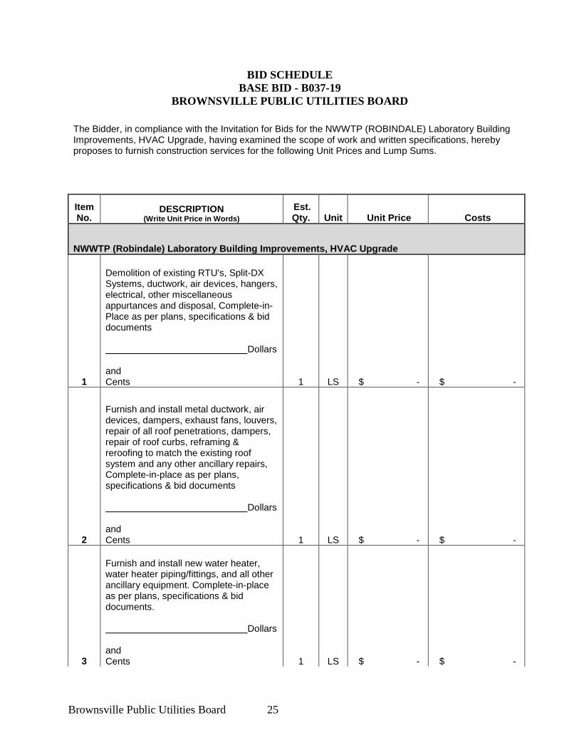
BID SCHEDULE BASE BID - B037-19
BROWNSVILLE PUBLIC UTILITIES BOARD
The Bidder, in compliance with the Invitation for Bids for the NWWTP (ROBINDALE) Laboratory Building Improvements, HVAC Upgrade, having examined the scope of work and written specifications, hereby proposes to furnish construction services for the following Unit Prices and Lump Sums.
Item No.
DESCRIPTION (Write Unit Price in Words)
Est. Qty. Unit Unit Price Costs
NWWTP (Robindale) Laboratory Building Improvements, HVAC Upgrade
1
Demolition of existing RTU's, Split-DX Systems, ductwork, air devices, hangers, electrical, other miscellaneous appurtances and disposal, Complete-in-Place as per plans, specifications & bid documents Dollars and Cents 1 LS $ - $ -
2
Furnish and install metal ductwork, air devices, dampers, exhaust fans, louvers, repair of all roof penetrations, dampers, repair of roof curbs, reframing & reroofing to match the existing roof system and any other ancillary repairs, Complete-in-place as per plans, specifications & bid documents Dollars and Cents 1 LS $ - $ -
3
Furnish and install new water heater, water heater piping/fittings, and all other ancillary equipment. Complete-in-place as per plans, specifications & bid documents. Dollars and Cents 1 LS $ - $ -
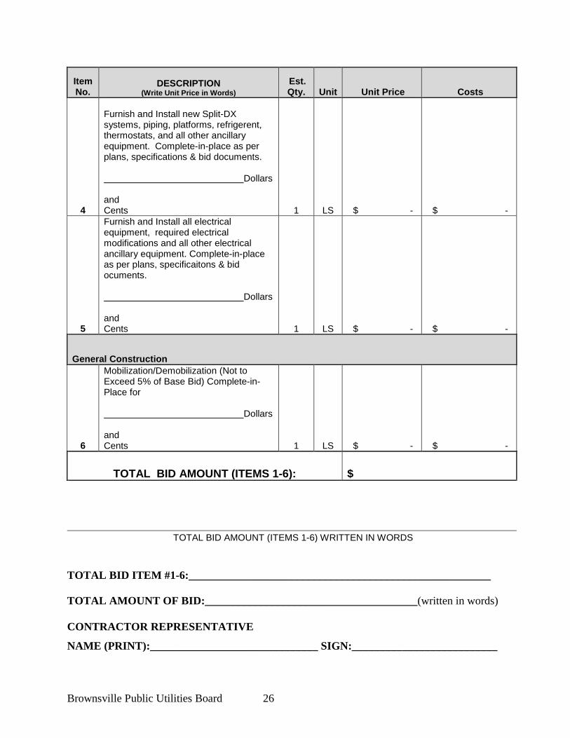
Brownsville Public Utilities Board 26
Item No.
DESCRIPTION (Write Unit Price in Words)
Est. Qty. Unit Unit Price Costs
4
Furnish and Install new Split-DX systems, piping, platforms, refrigerent, thermostats, and all other ancillary equipment. Complete-in-place as per plans, specifications & bid documents. Dollars and Cents 1 LS $ - $ -
5
Furnish and Install all electrical equipment, required electrical modifications and all other electrical ancillary equipment. Complete-in-place as per plans, specificaitons & bid ocuments. Dollars and Cents 1 LS $ - $ -
General Construction
6
Mobilization/Demobilization (Not to Exceed 5% of Base Bid) Complete-in-Place for Dollars and Cents 1 LS $ - $ -
TOTAL BID AMOUNT (ITEMS 1-6): $
TOTAL BID AMOUNT (ITEMS 1-6) WRITTEN IN WORDS
TOTAL BID ITEM #1-6:______________________________________________________ TOTAL AMOUNT OF BID:______________________________________(written in words)
CONTRACTOR REPRESENTATIVE
NAME (PRINT):______________________________ SIGN:__________________________
Brownsville Public Utilities Board 27
DATE: ____________________
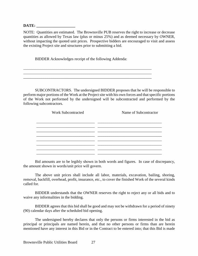
NOTE: Quantities are estimated. The Brownsville PUB reserves the right to increase or decrease quantities as allowed by Texas law (plus or minus 25%) and as deemed necessary by OWNER, without impacting the quoted unit prices. Prospective bidders are encouraged to visit and assess the existing Project site and structures prior to submitting a bid. BIDDER Acknowledges receipt of the following Addenda: __________________________________________________________________ __________________________________________________________________ __________________________________________________________________
SUBCONTRACTORS. The undersigned BIDDER proposes that he will be responsible to
perform major portions of the Work at the Project site with his own forces and that specific portions of the Work not performed by the undersigned will be subcontracted and performed by the following subcontractors.
Work Subcontracted Name of Subcontractor
______________________________ _________________________________ ______________________________ _________________________________ ______________________________ _________________________________ ______________________________ _________________________________ ______________________________ _________________________________ ______________________________ _________________________________ ______________________________ _________________________________ ______________________________ _________________________________
Bid amounts are to be legibly shown in both words and figures. In case of discrepancy,
the amount shown in words/unit price will govern. The above unit prices shall include all labor, materials, excavation, bailing, shoring,
removal, backfill, overhead, profit, insurance, etc., to cover the finished Work of the several kinds called for.
BIDDER understands that the OWNER reserves the right to reject any or all bids and to
waive any informalities in the bidding.
BIDDER agrees that this bid shall be good and may not be withdrawn for a period of ninety (90) calendar days after the scheduled bid opening.
The undersigned hereby declares that only the persons or firms interested in the bid as principal or principals are named herein, and that no other persons or firms than are herein mentioned have any interest in this Bid or in the Contract to be entered into; that this Bid is made
Brownsville Public Utilities Board 28
without connection with any other person, company, or parties likewise submitting a bid or bid; and that it is in all respects for and in good faith, without collusion or fraud.
Upon receipt of written notice of the acceptance of this bid, BIDDER will execute the formal Contract attached within ten (10) days and deliver the Bonds and Insurance Certificates as required under the GENERAL CONDITIONS. The Bid security attached in the sum of __________________________________ ($___________) is to become the property of the OWNER in the event the Contract, Bonds, and insurance certificates are not executed or delivered within the time above set forth, as mutually agreed to liquidated damages and not as a penalty for the delay and additional administrative expense to the OWNER caused thereby; otherwise the Bid security will be returned upon the signing of the Contract and delivering the approved Bonds and insurance certificates. Seal affixed here if BID is by a Corporation: Respectfully submitted, By:
Signature (Failure to sign will disqualify bid) Title Address Attest:
Brownsville Public Utilities Board 29
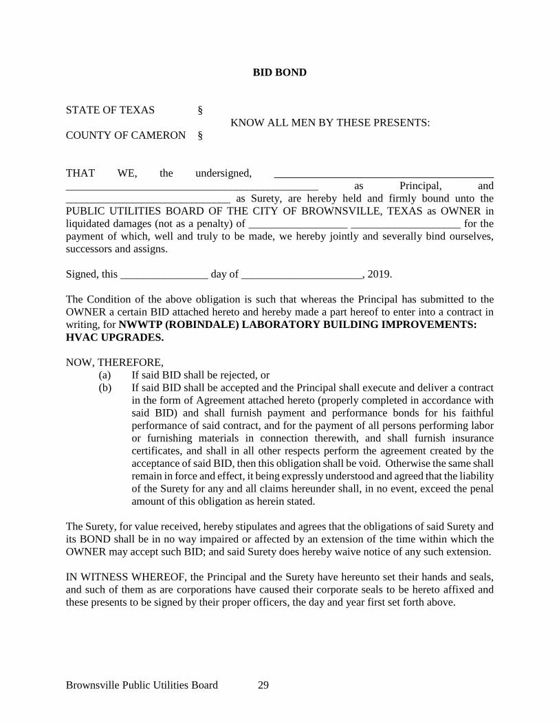
BID BOND STATE OF TEXAS §
KNOW ALL MEN BY THESE PRESENTS: COUNTY OF CAMERON § THAT WE, the undersigned, ________________________________________ ______________________________________________ as Principal, and ______________________________ as Surety, are hereby held and firmly bound unto the PUBLIC UTILITIES BOARD OF THE CITY OF BROWNSVILLE, TEXAS as OWNER in liquidated damages (not as a penalty) of __________________ ____________________ for the payment of which, well and truly to be made, we hereby jointly and severally bind ourselves, successors and assigns. Signed, this ________________ day of ______________________, 2019. The Condition of the above obligation is such that whereas the Principal has submitted to the OWNER a certain BID attached hereto and hereby made a part hereof to enter into a contract in writing, for NWWTP (ROBINDALE) LABORATORY BUILDING IMPROVEMENTS: HVAC UPGRADES. NOW, THEREFORE,
(a) If said BID shall be rejected, or (b) If said BID shall be accepted and the Principal shall execute and deliver a contract
in the form of Agreement attached hereto (properly completed in accordance with said BID) and shall furnish payment and performance bonds for his faithful performance of said contract, and for the payment of all persons performing labor or furnishing materials in connection therewith, and shall furnish insurance certificates, and shall in all other respects perform the agreement created by the acceptance of said BID, then this obligation shall be void. Otherwise the same shall remain in force and effect, it being expressly understood and agreed that the liability of the Surety for any and all claims hereunder shall, in no event, exceed the penal amount of this obligation as herein stated.
The Surety, for value received, hereby stipulates and agrees that the obligations of said Surety and its BOND shall be in no way impaired or affected by an extension of the time within which the OWNER may accept such BID; and said Surety does hereby waive notice of any such extension. IN WITNESS WHEREOF, the Principal and the Surety have hereunto set their hands and seals, and such of them as are corporations have caused their corporate seals to be hereto affixed and these presents to be signed by their proper officers, the day and year first set forth above.
Brownsville Public Utilities Board 30
Signed, this _____ day of __________________, 2019. ___________________________________ Principal ___________________________________ Surety By:________________________________ IMPORTANT - Surety companies executing BONDS must be legally authorized by the State Board of Insurance to transact business in the State of Texas.
Brownsville Public Utilities Board 31
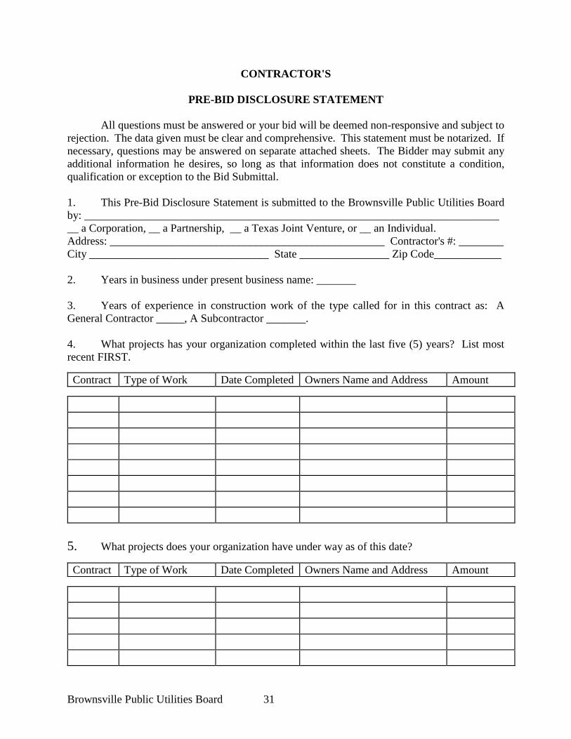
CONTRACTOR'S
PRE-BID DISCLOSURE STATEMENT
All questions must be answered or your bid will be deemed non-responsive and subject to rejection. The data given must be clear and comprehensive. This statement must be notarized. If necessary, questions may be answered on separate attached sheets. The Bidder may submit any additional information he desires, so long as that information does not constitute a condition, qualification or exception to the Bid Submittal. 1. This Pre-Bid Disclosure Statement is submitted to the Brownsville Public Utilities Board by: __________________________________________________________________________ __ a Corporation, __ a Partnership, __ a Texas Joint Venture, or __ an Individual. Address: _________________________________________________ Contractor's #: ________ City ________________________________ State ________________ Zip Code____________ 2. Years in business under present business name: _______ 3. Years of experience in construction work of the type called for in this contract as: A General Contractor _____, A Subcontractor _______. 4. What projects has your organization completed within the last five (5) years? List most recent FIRST.
Contract Type of Work Date Completed Owners Name and Address Amount
5. What projects does your organization have under way as of this date?
Contract Type of Work Date Completed Owners Name and Address Amount
Brownsville Public Utilities Board 32
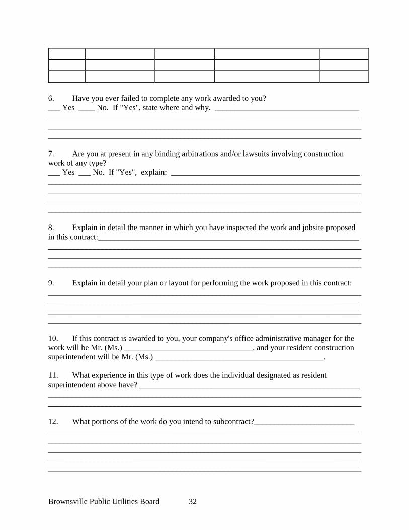
6. Have you ever failed to complete any work awarded to you? ___ Yes ____ No. If "Yes", state where and why. ____________________________________ __________________________________________________________________________________________________________________________________________________________________________________________________________________________________________ 7. Are you at present in any binding arbitrations and/or lawsuits involving construction work of any type? ___ Yes ___ No. If "Yes", explain: _______________________________________________ ________________________________________________________________________________________________________________________________________________________________________________________________________________________________________________________________________________________________________________________ 8. Explain in detail the manner in which you have inspected the work and jobsite proposed in this contract:_________________________________________________________________ __________________________________________________________________________________________________________________________________________________________________________________________________________________________________________ 9. Explain in detail your plan or layout for performing the work proposed in this contract: ________________________________________________________________________________________________________________________________________________________________________________________________________________________________________________________________________________________________________________________ 10. If this contract is awarded to you, your company's office administrative manager for the work will be Mr. (Ms.) ________________________________, and your resident construction superintendent will be Mr. (Ms.) __________________________________________. 11. What experience in this type of work does the individual designated as resident superintendent above have? _______________________________________________________ ____________________________________________________________________________________________________________________________________________________________ 12. What portions of the work do you intend to subcontract?_________________________ ______________________________________________________________________________________________________________________________________________________________________________________________________________________________________________________________________________________________________________________________________________________________________________________________________
Brownsville Public Utilities Board 33
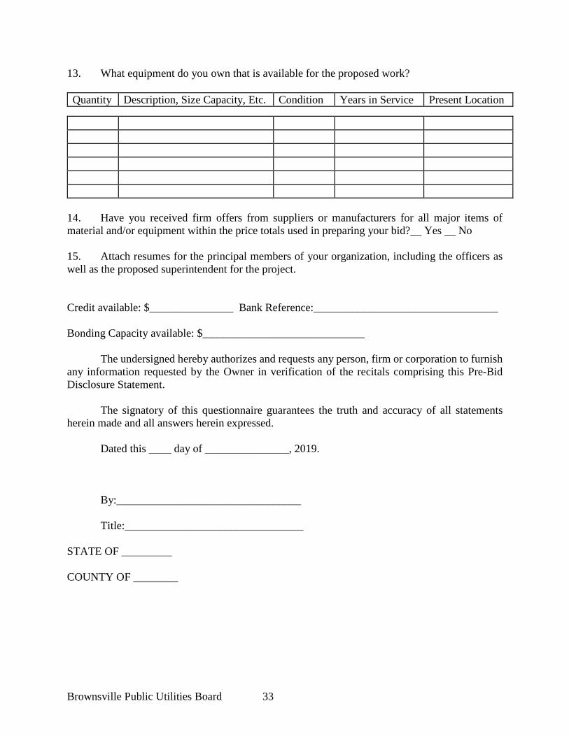
13. What equipment do you own that is available for the proposed work? Quantity Description, Size Capacity, Etc. Condition Years in Service Present Location
14. Have you received firm offers from suppliers or manufacturers for all major items of material and/or equipment within the price totals used in preparing your bid?__ Yes __ No 15. Attach resumes for the principal members of your organization, including the officers as well as the proposed superintendent for the project. Credit available: $_______________ Bank Reference:_________________________________ Bonding Capacity available: $_____________________________
The undersigned hereby authorizes and requests any person, firm or corporation to furnish
any information requested by the Owner in verification of the recitals comprising this Pre-Bid Disclosure Statement.
The signatory of this questionnaire guarantees the truth and accuracy of all statements herein made and all answers herein expressed.
Dated this ____ day of _______________, 2019.
By:_________________________________ Title:________________________________
STATE OF _________ COUNTY OF ________
Brownsville Public Utilities Board 34
Subscribed and sworn to before me this ____ day of _________, 2019.
____________________________________ Notary Public My commission expires: _____________
Brownsville Public Utilities Board 35
SUBCONTRACTOR'S PRE-BID DISCLOSURE STATEMENT
All questions must be answered or the general contractor’s bid will be deemed
non-responsive and subject to rejection. The data given must be clear and comprehensive. This statement must be notarized. If necessary, questions may be answered on separate attached sheets. The subcontractor may submit any additional information he desires. 1. This Pre-Bid Disclosure Statement is submitted to the Brownsville Public Utilities Board by: ______________________________________________________________________________ __ a Corporation, __ a Partnership, __ a Texas Joint Venture, or __ an Individual. Address: _________________________________________________ Contractor's #: ________ City ________________________________ State ________________ Zip Code____________ 2. Years in business under present business name: _______ 3. Years of experience in construction work of the type called for in this contract as: A General Contractor _____, A Subcontractor _______. 4. Have you ever previously worked as a subcontractor for this general contractor? __Yes___No; If yes, list the three most recent projects in which your company has served as a subcontractor to this general contractor. 5. What projects has your organization completed within the last five (5) years? List most recent FIRST.
Contract Type of Work Date Completed Owners Name and Address Amount
Brownsville Public Utilities Board 36
6. What projects does your organization have under way as of this date?
Contract Type of Work Date Completed Owners Name and Address Amount
7. Have you ever failed to complete any work awarded to you? ___ Yes ____ No. If "Yes", state where and why. ____________________________________ __________________________________________________________________________________________________________________________________________________________________________________________________________________________________________ 8. Are you at present in any finding arbitrations and/or lawsuits involving construction work of any type? ___ Yes ___ No. If "Yes", explain: _______________________________________________ ________________________________________________________________________________________________________________________________________________________________________________________________________________________________________________________________________________________________________________________ 9. Explain in detail the manner in which you have inspected the work and jobsite proposed in this contract:_________________________________________________________________ __________________________________________________________________________________________________________________________________________________________________________________________________________________________________________ 10. Explain in detail your plan or layout for performing the work proposed in this contract: ________________________________________________________________________________________________________________________________________________________________________________________________________________________________________________________________________________________________________________________ 11. If this subcontract is awarded to you by the general contractor, your company's office administrative manager for the work will be Mr. (Ms.) ________________________________, and your resident construction superintendent will be Mr. (Ms.) ________________________________________.
Brownsville Public Utilities Board 37
12. What experience in this type of work does the individual designated as resident superintendent above have? _______________________________________________________ ____________________________________________________________________________________________________________________________________________________________ 13. What portions of the work do you intend to subtier subcontract? ______________________________________________________________________________________________________________________________________________________________________________________________________________________________________________________________________________________________________________________________________________________________________________________________________ 14. What equipment do you own that is available for the proposed work? Quantity Description, Size Capacity, Etc. Condition Years in Service Present Location
15. Have you received firm offers from suppliers or manufacturers for all major items of material and/or equipment within the prices totals used in preparing your subcontractor bid? __ Yes __ No 16. Attach resumes for the principal members of your organization, including the officers as well as the proposed superintendent for the project. Credit available: $_________________ Bank Reference:_____________________________ Bonding Capacity available: $_________________________
The undersigned hereby authorizes and requests any person, firm or corporation to furnish any information requested by the Engineer and Owner in verification of the recitals comprising this Pre-Bid Disclosure Statement.
The signatory of this questionnaire guarantees the truth and accuracy of all statements herein made and all answers herein expressed.
Dated this ____ day of _______________, 2019.
Brownsville Public Utilities Board 38
By:_________________________________ Title:________________________________
STATE OF ________________________ COUNTY OF ______________________
Subscribed and sworn to before me this ____ day of _________, 2019. ____________________________________ Notary Public My commission expires: ________________
Brownsville Public Utilities Board 39
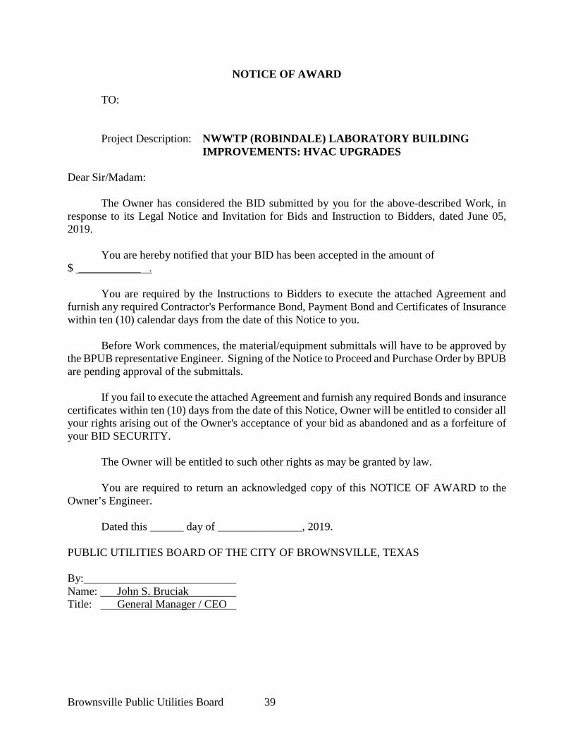
NOTICE OF AWARD
TO:
Project Description: NWWTP (ROBINDALE) LABORATORY BUILDING
IMPROVEMENTS: HVAC UPGRADES Dear Sir/Madam:
The Owner has considered the BID submitted by you for the above-described Work, in response to its Legal Notice and Invitation for Bids and Instruction to Bidders, dated June 05, 2019.
You are hereby notified that your BID has been accepted in the amount of $ ___________ .
You are required by the Instructions to Bidders to execute the attached Agreement and furnish any required Contractor's Performance Bond, Payment Bond and Certificates of Insurance within ten (10) calendar days from the date of this Notice to you. Before Work commences, the material/equipment submittals will have to be approved by the BPUB representative Engineer. Signing of the Notice to Proceed and Purchase Order by BPUB are pending approval of the submittals.
If you fail to execute the attached Agreement and furnish any required Bonds and insurance certificates within ten (10) days from the date of this Notice, Owner will be entitled to consider all your rights arising out of the Owner's acceptance of your bid as abandoned and as a forfeiture of your BID SECURITY.
The Owner will be entitled to such other rights as may be granted by law.
You are required to return an acknowledged copy of this NOTICE OF AWARD to the Owner’s Engineer.
Dated this ______ day of _______________, 2019. PUBLIC UTILITIES BOARD OF THE CITY OF BROWNSVILLE, TEXAS By: Name: John S. Bruciak Title: General Manager / CEO
Brownsville Public Utilities Board 40
ACCEPTANCE OF NOTICE Receipt of the above NOTICE OF AWARD is hereby acknowledged by: __________________________________________________________________ this ____ day of _______________, 2019. By: Name: Title:
Brownsville Public Utilities Board 41
NOTICE TO PROCEED TO: ADDRESS: Contract For: NWWTP (ROBINDALE) LABORATORY BUILDING IMPROVEMENTS: HVAC UPGRADES You are notified that the Contract Time under the above Contract will commence to run on ___________, 2019. By that date, you are to start performing your obligations under the Contract Documents. In accordance with the Agreement, the date of Substantial Completion prior to final payment is _________________, 2019. Before you may start any Work at the site, material submittals must be submitted and approved by the BPUB before a Purchase Order is issued and prior to the purchase and shipment of materials.
Brownsville Public Utilities Board: (Owner)
BY: _________________________ (Authorized Signature) DATE: _______________________ NAME: ___John S. Bruciak_______ TITLE: __General Manager/CEO__ FOR: Brownsville Public Utilities Board
Brownsville Public Utilities Board 42
AGREEMENT
THIS AGREEMENT is dated as of the _____ day of __________, 2019, by and between the PUBLIC UTILITIES BOARD of the City of Brownsville, Texas (hereinafter called OWNER) and ____________________ of ____________ an independent contractor, hereinafter called CONTRACTOR).
OWNER and CONTRACTOR, in consideration of the mutual covenants hereinafter set forth, agree as follows:
Article 1. WORK.
CONTRACTOR shall furnish all of the material, supplies, tools, equipment, labor and other services necessary for the construction and Final Completion of the Work described herein and complete all the Work as specified or indicated in the Contract Documents for NWWTP (ROBINDALE) LABORATORY BUILDING IMPROVEMENTS:HVAC UPGRADES.
Article 2. CONTRACT TIME
2.1 The Work shall be Substantially Completed and made ready for later final payment _One Hundred and Twenty (120) consecutive calendar days after the date when the Contract time commences to run as provided in paragraph 2.3 of the General Conditions and in the Notice to Proceed, and in accordance with paragraph 14.13 of the General Conditions.
2.2 Liquidated Damages. OWNER AND CONTRACTOR recognize that the
TIME OF PERFORMANCE IS OF THE ESSENCE in this Agreement and that OWNER will suffer financial loss if the Work is not Substantially Complete within the time specified in paragraph 2.1 above, plus any extensions thereof allowed in accordance with Article 12 of the General Conditions. Both parties hereto also recognize the delays, expense and difficulties involved in proving in a legal proceeding the actual loss suffered by OWNER if the Work is not Substantially Complete on time. Accordingly, instead of requiring such proof, OWNER and CONTRACTOR agree that as liquidated damages, and not as a penalty, for the delay, CONTRACTOR shall pay OWNER Three Hundred dollars ($300.00) for each consecutive calendar day that expires after the time specified in paragraph 2.1 for Substantial Completion.
Article 3. CONTRACT PRICE.
3.1 CONTRACTOR shall perform the Work described in the Contract
Documents for the amounts shown in the Bid Schedule, and OWNER shall pay CONTRACTOR in current funds based on the Bid Schedule.
Article 4. PAYMENT PROCEDURES.
Brownsville Public Utilities Board 43
Contractor shall submit Applications for Payment in accordance with Article 14 of the General Conditions. Applications for Payment will be processed by OWNER as provided for in the General Conditions.
4.1 Progress Payments. OWNER shall make progress payments on account of
the Contract Price on the basis of CONTRACTOR's Applications for Payment on or about the Twentieth (20th) day after submittal of the Application for Payment each month as provided below. All progress payments shall be on the basis of the progress of the Work measured by the Schedule of Values provided for in paragraph 14.1 of the General Conditions.
4.1.1 Prior to Substantial Completion, progress payments shall be in an
amount equal to 95% of the amount requested in the Application for Payment, with 5% remaining as retainage for the Project, to be released in accordance with paragraph 4.2.
4.1.2 Upon Substantial Completion, OWNER shall pay an amount
sufficient to increase total payments to CONTRACTOR to 95% of the Contract price, less such amounts OWNER shall determine in accordance with paragraph 14.7 of the General Conditions.
4.2 Final Payment. Upon Final Completion and acceptance of the Work in
accordance with paragraph 14.13 of the General Conditions, OWNER shall pay the remainder of the Contract price as provided in said paragraph 14.13.
Article 5. CONTRACTOR'S REPRESENTATIONS.
In order to induce OWNER to enter into this Agreement, CONTRACTOR makes the
following representations:
5.1 CONTRACTOR has familiarized himself with the nature and extent of the Contract Documents, Work, locality, and with all local conditions and federal, State and local laws, ordinances, rules and regulations that in any manner may affect cost, progress or performance of the Work.
5.2 CONTRACTOR has made or caused to be made examinations and
investigations of information and the Project site as he deems necessary for the performance of the Work at the Contract Price, within the Contract Time and in accordance with the other terms and conditions of the Contract Documents; and no additional examinations, investigations or similar data are or will be required by CONTRACTOR for such purposes.
5.3 CONTRACTOR has given OWNER written notice of all conflicts, errors
or discrepancies that he has discovered in the Contract Documents and the written resolution thereof by OWNER is acceptable to CONTRACTOR.
5.4 CONTRACTOR is skilled and experienced in the type of work described in
Brownsville Public Utilities Board 44
the Contract Documents.
Article 6. CONTRACT DOCUMENTS.
The Contract Documents which comprise the entire Agreement between OWNER and CONTRACTOR are attached to this Agreement, made a part hereof and consist of the following:
6.1 Legal Notice and Invitation to Bid
6.2 Instructions to Bidders
6.3 Bid and Bid Schedule
6.4 Bid Bond.
6.5 Contractor's and Subcontractor's Pre-Bid Disclosure Statements
6.6 Notice of Award and Acceptance of Notice
6.7 Notice to Proceed
6.8 Agreement
6.9 Performance Bond.
6.10 Payment Bond.
6.11 General Conditions
6.12 Supplementary General Conditions
6.13 Technical Specifications
6.14 Addendum number(s)
6.15 CONTRACTOR's Certificate(s) of Insurance.
6.16 Any written modification, including Change Orders, duly delivered after execution of this Agreement.
There are no Contract Documents other than those listed above in this Article 6. The Contract Documents may only be altered, amended or repealed by a written Modification (as defined in Article 1 of the General Conditions).
Article 7. MISCELLANEOUS.
Brownsville Public Utilities Board 45
7.1 Terms used in this Agreement, which are defined in Article 1 of the General Conditions shall have the meanings indicated in the General Conditions. 7.2 No assignment by a party hereto of any rights under or interests in the Contract Documents will be binding on another party hereto without the written consent of the party sought to be bound; and specifically, but without limitation, moneys that may become due and moneys that are due may not be assigned without such consent (except to the extent that this restriction may be limited by law), and unless specifically stated to the contrary in any written consent to an assignment, no assignment will release or discharge the assignor from any duty or responsibility under the Contract Documents.
7.3 OWNER and CONTRACTOR each binds himself, his partners, successors, assigns and legal representatives to the other party hereto, his partners, successors, assigns and legal representatives in respect to all covenants, agreements and obligations contained in the Contract Documents.
7.4 The invalidity or unenforceability of any provision of the Contract Documents shall not affect the validity or enforceability of any other provision of the Contract Documents.
7.5 This Agreement and the Contract Documents are subject to all applicable laws, statutes, codes, ordinances, rules and regulations.
7.6 In the event of default by CONTRACTOR under the Contract Documents, OWNER shall have all rights and remedies afforded to it at law or in equity to enforce the terms of the Contract Documents. The exercise of any one right or remedy shall be without prejudice to the enforcement of any other right or remedy allowed at law or in equity.
7.7 If any action at law or in equity is necessary by OWNER to enforce or interpret the terms of the Contract Documents, OWNER shall be entitled to reasonable attorneys' fees and costs and any necessary disbursements, in addition to any other relief to which the OWNER is entitled.
7.8 The Contract Documents constitute the entire agreement between the parties hereto and supersede all prior agreements, understandings, or oral communications between the parties. The Contract can only be modified or amended by written agreement of the parties.
7.9 These Contract Documents are governed by the laws of the State of Texas and the
parties agree that venue for any lawsuits arising from these Contract Documents shall be set in Cameron County, Texas.
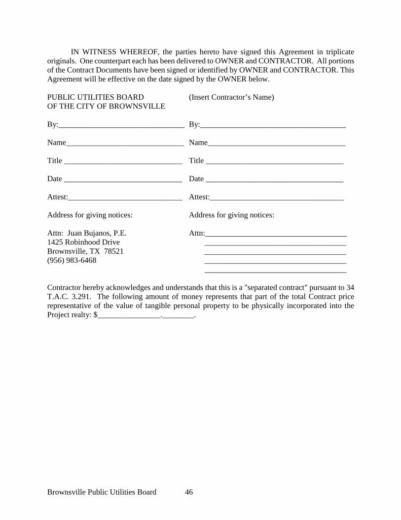
Brownsville Public Utilities Board 46
IN WITNESS WHEREOF, the parties hereto have signed this Agreement in triplicate originals. One counterpart each has been delivered to OWNER and CONTRACTOR. All portions of the Contract Documents have been signed or identified by OWNER and CONTRACTOR. This Agreement will be effective on the date signed by the OWNER below. PUBLIC UTILITIES BOARD (Insert Contractor’s Name) OF THE CITY OF BROWNSVILLE By:________________________________ By:_____________________________________ Name______________________________ Name___________________________________ Title ______________________________ Title ___________________________________ Date ______________________________ Date ___________________________________ Attest:_____________________________ Attest:__________________________________ Address for giving notices: Address for giving notices: Attn: Juan Bujanos, P.E. Attn:____________________________________ 1425 Robinhood Drive ____________________________________ Brownsville, TX 78521 ____________________________________ (956) 983-6468 ____________________________________ ____________________________________ Contractor hereby acknowledges and understands that this is a "separated contract" pursuant to 34 T.A.C. 3.291. The following amount of money represents that part of the total Contract price representative of the value of tangible personal property to be physically incorporated into the Project realty: $________________.________.
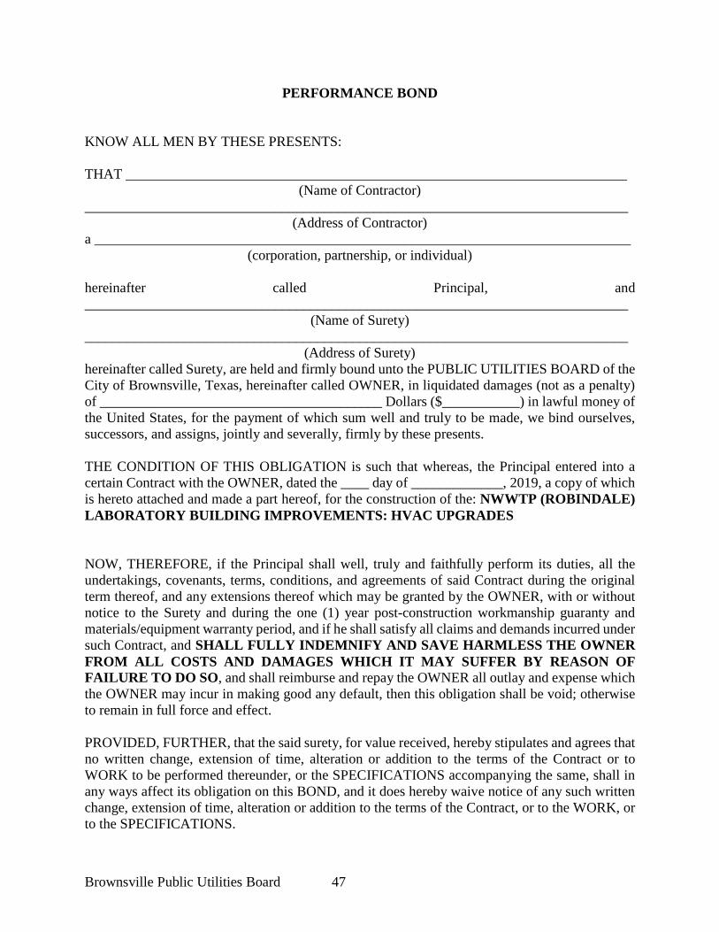
Brownsville Public Utilities Board 47
PERFORMANCE BOND KNOW ALL MEN BY THESE PRESENTS: THAT _______________________________________________________________________
(Name of Contractor) _____________________________________________________________________________
(Address of Contractor) a ____________________________________________________________________________
(corporation, partnership, or individual) hereinafter called Principal, and _____________________________________________________________________________
(Name of Surety) _____________________________________________________________________________
(Address of Surety) hereinafter called Surety, are held and firmly bound unto the PUBLIC UTILITIES BOARD of the City of Brownsville, Texas, hereinafter called OWNER, in liquidated damages (not as a penalty) of ________________________________________ Dollars ($___________) in lawful money of the United States, for the payment of which sum well and truly to be made, we bind ourselves, successors, and assigns, jointly and severally, firmly by these presents. THE CONDITION OF THIS OBLIGATION is such that whereas, the Principal entered into a certain Contract with the OWNER, dated the ____ day of _____________, 2019, a copy of which is hereto attached and made a part hereof, for the construction of the: NWWTP (ROBINDALE) LABORATORY BUILDING IMPROVEMENTS: HVAC UPGRADES NOW, THEREFORE, if the Principal shall well, truly and faithfully perform its duties, all the undertakings, covenants, terms, conditions, and agreements of said Contract during the original term thereof, and any extensions thereof which may be granted by the OWNER, with or without notice to the Surety and during the one (1) year post-construction workmanship guaranty and materials/equipment warranty period, and if he shall satisfy all claims and demands incurred under such Contract, and SHALL FULLY INDEMNIFY AND SAVE HARMLESS THE OWNER FROM ALL COSTS AND DAMAGES WHICH IT MAY SUFFER BY REASON OF FAILURE TO DO SO, and shall reimburse and repay the OWNER all outlay and expense which the OWNER may incur in making good any default, then this obligation shall be void; otherwise to remain in full force and effect. PROVIDED, FURTHER, that the said surety, for value received, hereby stipulates and agrees that no written change, extension of time, alteration or addition to the terms of the Contract or to WORK to be performed thereunder, or the SPECIFICATIONS accompanying the same, shall in any ways affect its obligation on this BOND, and it does hereby waive notice of any such written change, extension of time, alteration or addition to the terms of the Contract, or to the WORK, or to the SPECIFICATIONS.
Brownsville Public Utilities Board 48
PROVIDED, FURTHER, that no final settlement between the OWNER and the CONTRACTOR shall abridge the right of any beneficiary hereunder, whose claim may be unsatisfied. This bond is subject to and governed by Section 2253.02 of the Texas Government Code (Vernon's Texas Codes Annotated) and Article 7.19-1 of Vernon's Texas Insurance Code and all amendments thereto. IN WITNESS WHEREOF, this instrument is executed in triplicate, each counterpart of which shall be deemed an original, this the ____ day of ___________, 2019. ATTEST: __________________________________ (Principal) _____________________________________ By:_________________________________(s) (Principal) Secretary (Signature) (SEAL) _____________________________________ ______________________________________ (Witness as to Principal) (Address) _____________________________________ ______________________________________ (Address) _____________________________________ ATTEST: ____________________________________ (Surety) ____________________________________ By:____________________________________ (Surety) Secretary (Attorney-in-Fact) (SEAL) ____________________________________ _______________________________________ (Witness as to Surety) (Address) ____________________________________ _______________________________________ (Address) ____________________________________ NOTE: Date of BOND must not be prior to date of Contract. If Contractor is a Partnership, all partners should execute BOND. IMPORTANT: Surety companies executing BONDS must be legally authorized by the State Board of Insurance to transact business in the State of Texas.
Brownsville Public Utilities Board 49
ATTACH POWER OF ATTORNEY
Brownsville Public Utilities Board 50
PAYMENT BOND KNOW ALL MEN BY THESE PRESENTS: THAT _______________________________________________________________________
(Name of Contractor) _____________________________________________________________________________
(Address of Contractor) a ____________________________________________________________________________
(corporation, partnership, or individual) hereinafter called Principal, and _____________________________________________________________________________
(Name of Surety) _____________________________________________________________________________
(Address of Surety) hereinafter called Surety, are held and firmly bound unto the PUBLIC UTILITIES BOARD of the City of Brownsville, Texas, hereinafter called OWNER, in liquidated damages (not as a penalty) of ________________________________________ Dollars ($___________) in lawful money of the United States, for the payment of which sum well and truly to be made, we bind ourselves, successors, and assigns, jointly and severally, firmly by these presents. THE CONDITION OF THIS OBLIGATION is such that whereas, the Principal entered into a certain Contract with the OWNER, dated the ____ day of _____________, 2019, a copy of which is hereto attached and made a part hereof, for the construction of the: NWWTP (ROBINDALE) LABORATORY BUILDING IMPROVEMENTS: HVAC UPGRADES NOW, THEREFORE, if the Principal shall promptly make payment to all persons, firms, SUBCONTRACTORS, and corporations furnishing materials, for or performing labor in, the prosecution of the WORK provided for in such Contract, and any authorized extension or modification thereof, including all amounts due for materials, lubricants, oil, gasoline, repairs on machinery, equipment and tools, consumed or used in connection with the construction of such WORK, and all insurance premiums on said WORK, and for all labor, performed in such WORK whether by SUBCONTRACTOR or otherwise, then this obligation shall be void; otherwise to remain in full force and effect. PROVIDED, FURTHER, that the said surety, for value received hereby stipulates and agrees that no written change, extension of time, alteration or addition to the terms of the Contract or to WORK to be performed there under, or the SPECIFICATIONS accompanying the same, shall in any ways affect its obligation on this BOND, and it does hereby waive notice of any such written change, extension of time, alteration or addition to the terms of the Contract, or to the WORK, or to the SPECIFICATIONS. PROVIDED, FURTHER, that no final settlement between the OWNER and the CONTRACTOR shall abridge any remaining legal right of any beneficiary hereunder, whose timely filed and legally perfected claim may be unsatisfied.
Brownsville Public Utilities Board 51
This bond is subject to and governed by Section 2253.02 of the Texas Government Code (Vernon's Texas Codes Annotated) and Article 7.19-1 of Vernon's Texas Insurance Code and all amendments thereto. IN WITNESS WHEREOF, this instrument is executed in triplicate, each counterpart of which shall be deemed an original, this the ____ day of ___________, 2019. ATTEST: __________________________________ (Principal) _____________________________________ By:_________________________________(s) (Principal) Secretary (Signature) (SEAL) _____________________________________ ______________________________________ (Witness as to Principal) (Address) _____________________________________ ______________________________________ (Address) _____________________________________ ATTEST: ____________________________________ (Surety) ____________________________________ By:____________________________________ (Surety) Secretary (Attorney-in-Fact) (SEAL) ____________________________________ _______________________________________ (Witness as to Surety) (Address) ____________________________________ _______________________________________ (Address) ______________________________ NOTE: Date of BOND must not be prior to date of Contract. If Contractor Partnership, all partners should execute BOND. IMPORTANT: Surety companies executing BONDS must be legally authorized by the State Board of Insurance to transact business in the State of Texas.

Brownsville Public Utilities Board 52
ATTACH POWER OF ATTORNEY
Brownsville Public Utilities Board 53
ATTACHED CERTIFICATE OF INSURANCE
Brownsville Public Utilities Board 54
GENERAL CONDITIONS
OF THE
CONSTRUCTION CONTRACT
Prepared by The Public Utilities Board of the City of Brownsville, Texas as an Adaptation From the 1983 Base Document Prepared by
Engineers' Joint Contract Documents Committee
and originally
Issued and Published Jointly By:
PROFESSIONAL ENGINEERS IN PRIVATE PRACTICE A practice division of the
NATIONAL SOCIETY OF PROFESSIONAL ENGINEERS
-----------------------
AMERICAN CONSULTING ENGINEERS COUNCIL
-----------------------
AMERICAN SOCIETY OF CIVIL ENGINEERS
-----------------------
CONSTRUCTION SPECIFICATION INSTITUTE
The base document from which this adaptation was prepared
(1983 edition) was approved and endorsed by:
The Associated General Contractors of America
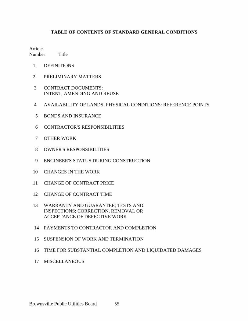
Brownsville Public Utilities Board 55
TABLE OF CONTENTS OF STANDARD GENERAL CONDITIONS Article Number Title 1 DEFINITIONS 2 PRELIMINARY MATTERS 3 CONTRACT DOCUMENTS: INTENT, AMENDING AND REUSE 4 AVAILABILITY OF LANDS: PHYSICAL CONDITIONS: REFERENCE POINTS 5 BONDS AND INSURANCE 6 CONTRACTOR'S RESPONSIBILITIES 7 OTHER WORK 8 OWNER'S RESPONSIBILITIES 9 ENGINEER'S STATUS DURING CONSTRUCTION 10 CHANGES IN THE WORK 11 CHANGE OF CONTRACT PRICE 12 CHANGE OF CONTRACT TIME 13 WARRANTY AND GUARANTEE; TESTS AND INSPECTIONS; CORRECTION, REMOVAL OR ACCEPTANCE OF DEFECTIVE WORK 14 PAYMENTS TO CONTRACTOR AND COMPLETION 15 SUSPENSION OF WORK AND TERMINATION 16 TIME FOR SUBSTANTIAL COMPLETION AND LIQUIDATED DAMAGES 17 MISCELLANEOUS
Brownsville Public Utilities Board 56
GENERAL CONDITIONS SCOPE. The Standard General Conditions of the Construction Contract prepared by the National Society of Professional Engineers (NSPE-1910-8, 1983 Edition) as amended and adapted by the OWNER to meet local requirements, shall form a part of this Contract, together with the following Supplementary General Conditions. A copy of the locally amended Standard General Conditions (based upon NSPE-1910-8) is bound herewith. The following supplements modify, change, delete, or add to the General Conditions. Where any part of the General Conditions is modified or voided by these Articles, the unaltered provisions of that part shall remain in effect. ARTICLE 1. DEFINITIONS Wherever used in these General Conditions or in the other Contract Documents, the following terms have the meanings indicated which are applicable to both the singular and plural thereof: Addenda - Written or graphic instruments issued prior to the opening of Bids which clarify, correct or change the bidding documents or the Contract Documents. These Addenda are a part of the Contract Documents and modify the Drawings, Specifications or other bid documents as indicated. No verbal changes in the Work not depicted or described in writing shall be binding. Supplements to, changes in, or corrections to the Drawings and/or Specifications issued in writing by OWNER during the period of bidding. These Addenda are a part of the Contract and modify the drawings and/or specifications as indicated. No verbal changes in the work as shown or described shall become binding. Agreement - The written and signed short-form Agreement (Contract) between OWNER and CONTRACTOR covering the Work to be performed; other Contract Documents including these General Conditions are attached to the Agreement and made a part thereof as provided therein. Alternates. Additions; deletions from; or changes to requirements for the Project, each of which shall be bid separately and shall be included in or deleted/deducted from the Contract at the discretion of OWNER. Application for Payment - The form developed by OWNER which is to be used by CONTRACTOR in requesting interim progress or final Contract payments and which is to include such supporting documentation as is required by the Contract Documents. Bid - The written offer or bid of the bidder submitted on the OWNER prescribed form setting forth in figures and in script, the prices for the Work to be performed. Bonds - Bid, Performance and Payment Bonds and any other instruments of security. Calendar Day - A calendar day of twenty-four hours is measured from midnight, to the next midnight, and shall constitute a single calendar day. Calendar days include Saturdays and Sundays. This is a Calendar Day Contract.
Brownsville Public Utilities Board 57
Change Order - A document developed by OWNER, which is signed by CONTRACTOR and OWNER and authorizes an addition, deletion or revision in the Work, or an adjustment in the Contract Price or the Contract Time, issued on or after the Effective Date of the Agreement. Approved Change Orders are part of the Contract Documents. Contract Documents - The Agreement, Addenda (which pertain to the Contract Documents), CONTRACTOR's Bid (including documentation accompanying the Bid and any post-Bid documentation submitted prior to the Notice of Award) when attached as an exhibit to the Agreement, the Bonds, these General Conditions, the Supplementary Conditions, the Specifications and the Drawings as the same are more specifically identified in the Agreement, together with all amendments, modifications, later approved Change Orders and supplements issued pursuant to paragraphs 3.4 and 3.5 on or after the Effective Date of the Agreement. Contract Price - The moneys payable by OWNER to CONTRACTOR under the Contract Documents as stated in the Agreement (subject to the provisions of paragraph 11.9.1 in the case of Unit Price Work). Contract Time - The number of days (“calendar” or “working” days computed as provided in paragraph 17.2) or the date specifically stated in the Agreement for the Substantial Completion of the Work. CONTRACTOR - The person, firm or corporation with whom OWNER has entered into the Agreement to construct the Work. Defective - An adjective which when modifying the word "Work" refers to "Work" that is unsatisfactory, faulty or deficient, or does not conform to, or comply with the Contract Documents, or does not meet the requirements of any inspection, referenced standard, test or approval referred to in the Contract Documents, or has been damaged prior to the time OWNER makes the final payment (unless responsibility for the protection thereof has been assumed by OWNER at Substantial Completion in accordance with paragraph 14.8 or 14.10). Drawings - The drawings (plans) which depict the character, design, and scope of the Work to be performed and which have been prepared and/or approved by OWNER and are referred to in the Contract Documents. Effective Date of the Agreement - The date indicated in the Agreement document upon which it becomes effective, but if no such date is indicated, it means the date on which the Agreement is signed by OWNER. Engineer- The OWNER - designated Brownsville P.U.B. in-house staff registered professional person, named as the OWNER's engineering representative for the Project. There is no outside independent engineering consultant anticipated to be retained by OWNER for this Project. Field Order - A written order issued by OWNER which orders minor changes or interpretations in the Work in accordance with paragraph 9.5, but which does not involve a change
Brownsville Public Utilities Board 58
in the Contract Price or the Contract Time. Furnish. To supply at the jobsite the material, equipment, etc., referred to. Installation is not required of the supplier by the specifications, but shall be arranged for by the General CONTRACTOR. General Requirements - Sections ____________ of the Specifications. Laws and Regulations; Laws or Regulations - Federal and/or State Laws, rules, administrative agency regulations, local ordinances, local codes and/or court orders. Notice of Award - The written notice by OWNER to the apparent successful bidder stating that upon compliance by the apparent successful bidder with the conditions precedent enumerated therein, within the time specified, OWNER will sign and deliver the Agreement. Notice to Proceed - A written notice given by OWNER to CONTRACTOR fixing the date on which the Contract Time will commence to run and on which CONTRACTOR shall start to perform CONTRACTOR's obligations under the Contract Documents. OWNER - The City of Brownsville, acting through its Public Utilities Board of the City of Brownsville, Texas and its authorized representatives. Partial Utilization - Placing a portion of the Work in service for the benefit of the OWNER and for the purpose for which it is intended (or a related purpose) before reaching Substantial Completion for all the Work. Project - The total construction of which the Work to be provided under the Contract Documents may be the whole, or a part as indicated elsewhere in the Contract Documents. Provide. To furnish and install the material, equipment, etc. referred to, at the location shown or otherwise approved at the Project job-site. Resident Project Representative - The authorized representative of OWNER who is assigned to periodically observe the site of the Project, or any part thereof, on behalf of OWNER. Shop Drawings - All drawings, diagrams, illustrations, schedules and other data which are specifically prepared by, or for CONTRACTOR, to illustrate some portion of the Work, and all illustrations, brochures, standard schedules, performance charts, instructions, diagrams and other information prepared by a Supplier and submitted by CONTRACTOR, to illustrate material or equipment for some portion of the Work. Specifications - Those portions of the Contract Documents consisting of written technical descriptions for the design configuration and/or performance standard of materials, equipment, any specified construction systems, standards and workmanship, as applied to the Work and certain administrative details applicable thereto. Standard Abbreviations. Wherever reference is made to standard specifications,
Brownsville Public Utilities Board 59
standards of quality or performance, as established by a recognized national authority, the reference may be by initials and acronyms as generally recognized throughout the industry. Subcontractor - An individual, firm or corporation having a direct contract with CONTRACTOR, or with any other Subcontractor (subtier), for the performance of a part of the Work at the Project site. Substantial Completion - (See generally paragraph 14.8) The Work (or a specified part thereof) has progressed to the point where, in the opinion of OWNER as evidenced by its definitive written and signed certificate of Substantial Completion, it is apparently sufficiently complete, in accordance with the Contract Documents, so that the Work (or specified part) can be utilized for the OWNER’s purposes for which it is intended; or if there is no such certificate issued, when final payment is due in accordance with paragraph 14.13. The terms "Substantially Complete" and "Substantially Completed" as applied to any Work refer to the Substantial Completion thereof. Supplementary Conditions - The part of the Contract Documents which amends or supplements these General Conditions. Supplier - A manufacturer, fabricator, supplier, distributor, materialman or third-party vendor. Underground Facilities - All pipelines, conduits, ducts, cables, wires, manholes, vaults, tanks, tunnels or other such facilities or attachments, and any outer encasements containing such facilities (vaults) which have been installed underground to furnish/transport any of the following services or materials: electricity, gases, steam, liquid petroleum products, telephone or other related data communications, cable television, sewage, storm drainage, traffic or other electronic control systems or potable water. Unit Price Work - Work to be paid for on the basis of unit prices for OWNER estimated quantities. Work - The entire completed construction or the various separately identifiable parts thereof, required to be furnished by the CONTRACTOR under the Contract Documents. Work is the result of performing services, furnishing labor and furnishing and incorporating materials and equipment into the construction, all as required by the Contract Documents. Work Directive Change - A written directive to CONTRACTOR, issued on or after the Effective Date of the Agreement and signed by OWNER, ordering an addition, deletion or revision in the Work, or responding to differing or unforeseen physical conditions under which the Work is to be performed as provided in paragraph 4.2 or 4.3 or to emergencies under paragraph 6.22. A Work Directive Change may not change the Contract Price or the Contract Time, but is evidence that the parties expect that the change directed or documented by a Work Directive Change will be incorporated in a subsequently issued Change Order following negotiations by the parties as to its effect, if any, on the Contract Price or Contract Time as provided in paragraph 10.2. Working Day. A week day (Monday through Friday only, inclusive) in which weather conditions are such that Work can be performed in a normal manner. Weekends (Saturday,
Brownsville Public Utilities Board 60
Sunday) and holidays shall not be considered working days. This Contract is not a Working Day Contract. Written Amendment - A written amendment of the Contract Documents, signed by OWNER and CONTRACTOR on or after the Effective Date of the Agreement and normally dealing with the non-engineering or non-technical (commercial terms, legal provisions, etc.), rather than strictly Work-related, aspects of the Contract Documents. Written Amendments are normally embodied in a Change Order once construction commences. ARTICLE 2. PRELIMINARY MATTERS Delivery of Bonds: 2.1 When CONTRACTOR delivers the executed Agreements to OWNER, CONTRACTOR shall also deliver to OWNER such Bonds as CONTRACTOR may be required to furnish in accordance with paragraph 5.1. Copies of Documents: 2.2 OWNER shall furnish to CONTRACTOR up to five (5) copies (unless otherwise specified in the Supplementary Conditions) of the Contract Documents as are reasonably necessary for the execution of the Work. Additional copies will be furnished to CONTRACTOR, upon request, at the cost of reproduction reimbursable to OWNER. Commencement of Contract Time; Notice to Proceed: 2.3 The Contract Time will commence to run on the date indicated in the Notice to Proceed. A Notice to Proceed may be given by Owner at any time after the Effective Date of the Agreement. The CONTRACTOR might not yet be actually performing Work after Contract Time commences. Starting the Project: 2.4 CONTRACTOR is obligated to perform the Work on the date when the Contract Time commences to run, but no Work shall be done at the Project site prior to the date on which the Contract Time commences to run per the Notice to Proceed. Before Starting Construction: 2.5 Before undertaking each part of the Work, CONTRACTOR shall carefully study and compare the Contract Documents and check and verify pertinent figures shown thereon and all applicable field measurements. CONTRACTOR shall promptly report in writing to OWNER any conflict, error or discrepancy which CONTRACTOR may discover and shall obtain a written interpretation or clarification from OWNER's Engineer before proceeding with any Work affected thereby, however CONTRACTOR shall not be liable to OWNER for failure to report any conflict, error or discrepancy in the Contract Documents, unless CONTRACTOR had actual knowledge thereof or should reasonably have known thereof pursuant to customary construction industry
Brownsville Public Utilities Board 61
standards. 2.6 Within ten (10) calendar days after the Effective Date of the Agreement (unless otherwise specified in the General Requirements), CONTRACTOR shall submit to OWNER for review: 2.6.1 an estimated Work Progress Schedule indicating the starting and completion dates of the various critical stages of the Work; and a preliminary schedule of Shop Drawing submissions; and 2.6.2 a preliminary Schedule of Values for all of the Work, which will include quantities and prices of items aggregating the total Contract Price and will subdivide the Work into logical component parts in sufficient detail to serve as the basis for progress payments during construction. Such prices will include an appropriate amount of overhead and profit applicable to each item of Work which will be automatically confirmed in writing by CONTRACTOR at the time of submission to OWNER. 2.7 By the tenth (10th) calendar day after award of the Contract by OWNER, CONTRACTOR shall deliver to OWNER original certificates (and any other evidence of insurance requested by OWNER) which CONTRACTOR is required to purchase and maintain in accordance with Article 5. Preconstruction Conference: 2.8 After the Effective Date of the Agreement, but before CONTRACTOR starts the Work at the Project site, a mandatory conference attended by CONTRACTOR, OWNER and others as appropriate, will be held to discuss the Schedules referred to in paragraph 2.6, to discuss procedures for handling Shop Drawings and other submittals and for processing Applications for Payment; and to establish a working and pragmatic understanding among the parties as to the general progress and administration of the Work. Finalizing Schedules: 2.9 At least ten (10) calendar days before submission of the first Application for Payment, a mandatory conference attended by CONTRACTOR, OWNER and others as appropriate, will be held to finalize the Schedules submitted in accordance with paragraph 2.6. The finalized Progress Schedule will be made acceptable to OWNER as providing an orderly progression of the Work to completion within the Contract Time, but such OWNER acceptance will neither impose on OWNER responsibility for the progress or scheduling of the Work, nor relieve CONTRACTOR from full responsibility therefore. The finalized Schedule of Shop Drawing submissions will be acceptable to OWNER's Engineer as providing a workable arrangement for processing the submissions for review. The finalized Schedule of Values will be made acceptable to OWNER's Engineer as to form and substance. ARTICLE 3. CONTRACT DOCUMENTS: INTENT, AMENDING, REUSE
Brownsville Public Utilities Board 62
Intent: 3.1 The Contract Documents comprise the entire agreement between OWNER and CONTRACTOR concerning the Work. The Contract Documents are complementary; what is called for by one is as binding as if called for by all. The Contract Documents will be construed in accordance with the law of Cameron County, Texas. 3.2 It is the intent of the Contract Documents to describe a functionally complete Project (or part thereof) to be constructed in accordance with the Contract Documents. Any Work, materials or equipment that may reasonably be inferred from the Contract Documents as being required of CONTRACTOR to produce the OWNER’S intended result will be supplied by CONTRACTOR, whether or not specifically called for. When words which have a well-known technical or trade meaning are used to describe Work, materials or equipment, such words shall be interpreted in accordance with that meaning. Reference to standard specifications, manuals or codes of any technical society, organization or association, whether such reference be specific or by implication, shall mean the latest amended standard specification, manual, code or Laws or Regulations in effect at the time of opening of Bids (or, on the Effective Date of the Agreement, if there were no Bids), except as may be otherwise specifically stated. However, no provision of any referenced standard specification, manual or code (whether or not specifically incorporated by reference in the Contract Documents) shall be effective to change the duties and responsibilities of OWNER, CONTRACTOR, or any of their consultants, agents or employees from those set forth in the Contract Documents. Clarifications and interpretations of the Contract Documents shall be issued by OWNER's Engineer in writing as provided in paragraph 9.4. 3.3 If, during the performance of the Work, CONTRACTOR finds a conflict, error or discrepancy in the Contract Documents, CONTRACTOR shall so report to OWNER's Engineer in writing immediately, and before proceeding with the Work affected thereby, and CONTRACTOR shall obtain a written interpretation or clarification from OWNER's Engineer, however, CONTRACTOR shall not be liable to OWNER for failure to report any conflict, error or discrepancy in the Contract Documents unless CONTRACTOR had actual knowledge thereof, or should reasonably have known thereof pursuant to customary construction industry standards. Amending and Supplementing Contract Documents: 3.4 The Contract Documents may be amended to provide for additions, deletions and revisions in the Work or to modify the terms and conditions thereof in one or more of the following written ways: 3.4.1 a formal Written Amendment, 3.4.2 a Change Order (pursuant to paragraph 10.4), or 3.4.3 a Work Directive Change (pursuant to paragraph 10.1). As indicated in paragraphs 11.2 and 12.1, Contract Price and Contract Time may only be changed by a Change Order or a Written Amendment.
Brownsville Public Utilities Board 63
3.5 In addition, the requirements of the Contract Documents may be supplemented, and minor variations and deviations in the Work may be authorized, in one or more of the following ways: 3.5.1 a Field Order (pursuant to paragraph 9.5), 3.5.2 OWNER Engineer's approval of a Shop Drawing or sample (pursuant to paragraphs 6.26 and 6.27), or 3.5.3 OWNER Engineer's written interpretation or clarification (pursuant to paragraph 9.4). Reuse of Documents: 3.6 Neither CONTRACTOR nor any Subcontractor or Supplier, or other person or organization performing or furnishing any of the Work under a direct contract or Project involvement with OWNER, shall have or acquire any title to, or ownership rights in, any of the Drawings, Specifications or other Contract Documents (or copies of any thereof) prepared by or bearing the seal of OWNER's Engineer, and they shall not reuse any of them on extensions of the Project or any other project without written consent of OWNER and specific written verification or adaptation by OWNER's Engineer. All Drawings, Specifications or other Documents (or copies of any thereof) are upon completion of the Project to become the property of OWNER. Further use thereof without written consent of OWNER and OWNER’S Engineer is prohibited and solely at the risk of the user. ARTICLE 4. AVAILABILITY OF LANDS: PHYSICAL CONDITIONS: REFERENCE POINTS Availability of Lands: 4.1 OWNER shall furnish, as indicated in the Contract Documents, the lands upon which the Work is to be performed, rights-of-way, licenses and easements for access thereto and such other lands which are specifically designated by OWNER for the use of CONTRACTOR. Easements for permanent structures or permanent changes in existing facilities will be obtained and paid for by OWNER, unless otherwise provided in the Contract Documents. If CONTRACTOR believes that any delay in OWNER's furnishing of these lands, rights-of-way, licenses or easements entitles CONTRACTOR to an extension of the Contract Time, CONTRACTOR may make a claim therefore as provided in Article 12. CONTRACTOR shall provide at his sole cost and option for any and all additional lands and access thereto not specifically provided by OWNER that CONTRACTOR may perceive are required for staging, temporary construction facilities, or storage of materials and equipment. 4.2 Physical Condition: 4.2.1 Explorations and Reports: Reference is made to the Supplementary
Brownsville Public Utilities Board 64
Conditions for any identification of any reports of geotechnical explorations and tests of subsurface conditions at the Project site that may have been utilized by OWNER's Engineer in preparation of the Contract Documents. Any of these geotechnical Explorations and Reports are expressly not part of these Contract Documents. CONTRACTOR may not rely upon the accuracy of the technical data contained in any such reports, nor upon non-technical data, interpretations or opinions contained therein or for the completeness thereof for CONTRACTOR's purposes. Except as indicated in the immediately preceding sentence and in paragraph 4.2.6, CONTRACTOR shall have full responsibility with respect to exploring, testing and encountering any subsurface conditions at the Project site. 4.2.2 Existing Structures: Reference is made to the Supplementary Conditions for any identification of those Drawings of physical conditions in or relating to existing surface or subsurface structures (except Underground Facilities referred to in paragraph 4.3) which are at or contiguous to the Project site that have been utilized by OWNER's Engineer in preparation of the Contract Documents. CONTRACTOR may rely upon the accuracy of the technical data actually contained in such drawings, but not for the current conditions or completeness thereof for CONTRACTOR's purposes. Except as indicated in the immediately preceding sentence and in paragraph 4.2.6, CONTRACTOR shall have full responsibility with respect to current locating, verification, investigation of, and encountering physical conditions in or relating to such structures. 4.2.3. Report of Differing Conditions: If CONTRACTOR believes that: 4.2.3.1 any technical data on which CONTRACTOR is entitled to rely as provided in paragraphs 4.2.1 and 4.2.2 is inaccurate, or 4.2.3.2 any physical condition uncovered or revealed at the Project site differs materially from that indicated, reflected or referred to in the Contract Documents, CONTRACTOR shall, promptly after becoming aware thereof and before performing any Work in connection therewith (except in an emergency as permitted by paragraph 6.22), notify OWNER's field representative and OWNER's Engineer in writing about the inaccuracy or difference. 4.2.4 OWNER's Review: OWNER's Engineer will promptly review the pertinent conditions, determine the necessity of either CONTRACTOR or OWNER obtaining additional physical or geotechnical explorations or tests with respect thereto, and advise CONTRACTOR in writing of the findings and conclusions. 4.2.5 Possible Document Change: If OWNER's Engineer concludes that there is a material error in the Contract Documents, or that because of newly discovered, latent physical conditions, a change in the Contract Documents is required, a Work Directive Change or a Change Order may be issued as provided in Article 10 to reflect and document the consequences of the inaccuracy or difference. 4.2.6 Possible Price and Time Adjustments: In each such case, an increase or decrease in the Contract Price or an extension or shortening of the Contract Time, or any combination thereof, may be allowable to the extent that they are attributable to any such inaccuracy or difference. If OWNER and CONTRACTOR are unable to agree as to the amount
Brownsville Public Utilities Board 65
or length thereof, a CONTRACTOR claim may be made therefore as provided in Articles 11 and 12. All increases or decreases in the Contract Price shall be governed by all State and local statutes, codes, laws, ordinances, rules and regulations governing public competitive bidding and Change Orders. Physical Conditions 4.3 Underground Facilities: 4.3.1 Shown or Indicated: The information and data shown or indicated in the Contract Documents with respect to existing Underground Facilities at or contiguous to the Project site is only based on existing available information and data furnished to OWNER by the owners of such Underground Facilities, (utilities, pipeline companies, railroads, etc.) or by others. Unless it is otherwise expressly provided in the Supplementary Conditions: 4.3.1.1 OWNER shall not be responsible for the actual current conditions, accuracy or completeness of any such third-party information or data; and, 4.3.1.2 CONTRACTOR shall have full responsibility for reviewing and checking all such current information and data; for locating all current Underground Facilities shown or indicated in the Contract Documents, for coordination of the Work with the owners of such Underground Facilities during construction; for the safety and protection thereof as provided in paragraph 6.20 and; paying for the repair of any damage thereto resulting from the Work; the cost of all of which will be mutually considered between OWNER and CONTRACTOR as having been included in the CONTRACTOR'S original Contract Price. 4.3.2 Not Shown or Indicated: If an Underground Facility is uncovered or revealed at or contiguous to the Project site which was not shown or indicated in the Contract Documents, and which CONTRACTOR could not reasonably have been expected to be aware of under customary construction industry standards, CONTRACTOR shall, promptly after becoming aware thereof and before performing any Work affected thereby (except in an emergency as permitted by paragraph 6.22), identify the owner of such Underground Facility and give written notice thereof to that owner and to OWNER's Engineer. OWNER's Engineer will promptly review the Underground Facility to determine the extent to which the Contract Documents should be modified to reflect and document the consequences of the existence of the Underground Facility, and the Contract Documents may be amended or supplemented to the extent necessary. During such time, CONTRACTOR shall be responsible for the safety and protection of such Underground Facility as provided in paragraph 6.20. CONTRACTOR may be allowed an increase in the Contract Price or an extension of the Contract Time, or both, to the extent that they are attributable to the existence of any Underground Facility that was not shown or indicated in the Contract Documents, and which CONTRACTOR could not reasonably have been expected to be aware of pursuant to customary construction industry standards. If the parties are unable to agree as to the amount or length thereof, CONTRACTOR may make a claim therefore as provided in Articles 11 and 12. All increases or decreases in the Contract Price shall be governed by all State and local statutes, codes, laws, ordinances, rules and regulations governing public competitive bidding and Change Orders.
Brownsville Public Utilities Board 66
Reference Points: 4.4. OWNER shall provide CONTRACTOR with any reasonably current and existing engineering surveys to assist CONTRACTOR to establish reference points for construction, which in OWNER Engineer's judgment are adequate to enable a skilled CONTRACTOR to proceed with the Work pursuant to customary construction industry standards. CONTRACTOR shall be responsible for laying out the Work (unless otherwise specifically specified by OWNER in the General Requirements), and shall protect and preserve the established reference points and shall make no changes or relocations without the prior written approval of OWNER. CONTRACTOR shall report to OWNER's Engineer whenever any reference point is lost or destroyed or requires relocation because of necessary changes in grades or locations, and CONTRACTOR shall be responsible for the accurate replacement or relocation of such reference points by professionally qualified personnel. ARTICLE 5. BONDS AND INSURANCE Performance and Payment Bonds: For a Contract in excess of $100,000.00, a Performance Bond shall be executed in the full amount of the Contract conditioned upon the faithful performance of the Work in accordance with the Plans, Specifications and Contract Documents. Said Bond shall be solely for the protection of the OWNER. For a Contract in excess of $50,000.00, a Payment Bond shall be executed in the full amount of the Contract, solely for the primary protection of all proper claimants against the surety for payment in supplying labor and material in the prosecution of the Work provided for in the Contract, for the use of each such claimant timely perfecting a proper claim against surety. 5.1 CONTRACTOR shall furnish Performance and Payment Bonds, each in an amount at least equal to the Contract Price as security for the faithful performance of the Work and payment of all CONTRACTOR's labor, materials and supply obligations under the Contract Documents. These bonds shall remain in effect at least until one year after the date when final payment becomes due, except as otherwise provided by Law or Regulation or by the Contract Documents. CONTRACTOR shall also furnish any such other Bonds as may be required by the Supplementary Conditions. All Bonds shall be in the forms prescribed by Law or Regulation or by the Contract Documents and be executed by such sureties as are authorized to do business in the State of Texas. All Bonds signed by an agent must be accompanied by a certified copy of the authority to act on behalf of the surety. 5.2 If the surety on any Bond furnished by CONTRACTOR is declared a bankrupt or becomes insolvent, or its right to do business is terminated in Texas or it ceases to meet the requirements of paragraph 5.1, CONTRACTOR shall within five (5) calendar days thereafter substitute another Bond or surety, both of which must be acceptable to OWNER. Contractor's Liability Insurance: 5.3 CONTRACTOR shall purchase and maintain such commercial general liability and
Brownsville Public Utilities Board 67
other insurance coverages as are appropriate for the Work being performed and furnished, and as will provide protection from claims set forth below which may arise out of, or result from, CONTRACTOR's performance and furnishing of the Work and CONTRACTOR's other obligations under the Contract Documents; whether it is to be performed or furnished by CONTRACTOR, by any Subcontractor, by anyone directly or indirectly employed by any of them to perform or furnish any of the Work; or by anyone for whose acts and/or omissions any of them may be liable: 5.3.1 Claims under workers' compensation, disability benefits and other similar employee benefit acts. This is a Texas public works Contract and rejection of the worker’s compensation act, and thereby substituting a CONTRACTOR’S self-insurance reserve, is specifically disallowed. 5.3.2 Claims for damages because of bodily injury, occupational sickness or disease, or death of CONTRACTOR's employees traditionally covered by employer’s liability insurance; 5.3.3 Claims for damages because of bodily injury, sickness or disease, or death of any person other than CONTRACTOR's employees; 5.3.4 Claims for damages insured by personal injury liability coverage which are sustained (a) by any person as a result of an offense directly or indirectly related to the employment of such person by CONTRACTOR; or (b) by any other person for any other reason; 5.3.5 Claims for damages, other than to the Work itself, because of injury to or destruction of tangible property wherever located, including loss of use resulting there from; 5.3.6 Claims arising out of operation of Laws or Regulations for damages because of bodily injury or death of any person or for damage to property; and 5.3.7 Claims for damages because of bodily injury or death of any person or property damage arising out of the ownership, maintenance or use of any owned or hired motor vehicle. The various insurance coverages required by these paragraphs 5.3 and 5.6 shall include the specific type coverage and be written for not less than the limits of liability and coverage amounts provided herein below or in the Supplementary Conditions, or required by law, whichever is greater. The commercial general liability insurance shall include completed operations insurance. All of the policies of insurance so required to be purchased and maintained (or the certificates or other evidence thereof) shall be of an "occurrence"-type, when applicable, and shall contain a provision or endorsement that the coverage afforded will not be canceled, materially changed or renewal refused until at least (30) thirty days prior written notice has been given to OWNER by certified mail. All such insurance shall remain in effect until final payment and at all times thereafter when CONTRACTOR may be correcting, removing or replacing defective Work in accordance with paragraph 13.12. In addition, CONTRACTOR shall maintain such completed operations insurance for at least two (2) years after final payment and furnish OWNER with evidence of continuation of such insurance at final payment and one year thereafter. All insurance coverage
Brownsville Public Utilities Board 68
furnished under the Contract Documents shall include the City of Brownsville and BPUB as OWNER, and their respective public officials, officers, board members, and employees, as named additional insureds and hereinafter known as "additional insureds." Contractual Liability Insurance: 5.4 The Commercial general liability insurance required by paragraph 5.3 will include contractual liability insurance applicable to CONTRACTOR's INDEMNITY obligations under paragraphs 6.32 and 6.33. 5.5 Specific Coverages of Insurance Required by Owner: 5.5.1 Workmen's Compensation and Employer's Liability. This insurance shall protect the laborer, and insure the CONTRACTOR, and insulate the additional insureds, against all claims under applicable Texas workmen's compensation laws, pursuant to Section 5.3.1. The additional insureds shall also be protected under an Employer's Liability policy against claims for injury, disease, or death of employees which, for any reason, may not fall within the provisions of a workmen's compensation law. This Employer’s Liability policy shall include an "all states" endorsement.
5.5.2. Mandatory TWCC Rule 28 TAC Sect. 110.110 Language
(A) Definitions:
Certificate of coverage ("certificate") - A copy of a certificate of insurance, a certificate of authority to self-insure issued by the Commission, or a coverage agreement (TWCC-81, TWCC- 82, TWCC-83, or TWCC-84), showing statutory workers' compensation insurance coverage for the person's or entity's (CONTRACTOR’s) employees providing services on a Project, for the duration of the Project.
“Duration of the Project” - includes the time from the beginning of the Work on the Project until the CONTRACTOR's/person's Work on the Project has been completed and accepted by the OWNER.
“Persons providing services on the Project” ("subcontractor" in § 406.096) - includes all persons or entities performing all or part of the services the CONTRACTOR has undertaken to perform on the Project, regardless of whether that person contracted directly with the CONTRACTOR and regardless of whether that person has employees. This includes, without limitation, independent contractors, subcontractors, leasing companies, motor carriers, owner-operators, employees of any such entity, or employees of any entity which furnishes persons to provide services on the Project. "Services" - include, without limitation, providing, hauling, or delivering equipment or materials, or providing labor, transportation, or other service related to a Project.
Brownsville Public Utilities Board 69
(B) The CONTRACTOR shall provide coverage, based on proper reporting of
classification codes and payroll amounts and filing of any coverage agreements, which meets the statutory requirements of Texas Labor Code, § 401.011(44) for all employees of the CONTRACTOR providing services on the Project, for the duration of the Project.
(C) The CONTRACTOR must provide a certificate of coverage to the OWNER prior
to being awarded the Contract.
(D) If the coverage period shown on the CONTRACTOR'S current certificate of coverage ends during the duration of the Project, the CONTRACTOR must, prior to the end of the coverage period, file a new certificate of coverage with the OWNER showing that coverage has been extended.
(E) The CONTRACTOR shall obtain from each person providing services on a Project,
and provide to the OWNER:
(1) a certificate of coverage, prior to that person beginning Work on the Project, so the OWNER will have on file certificates of coverage showing coverage for all persons providing services on the Project; and
(2) no later than seven (7) calendar days after receipt by the CONTRACTOR,
a new certificate of coverage showing extension of coverage, if the coverage period shown on the current certificate of coverage ends during the duration of the Project.
(F) The CONTRACTOR shall retain all required certificates of coverage for the
duration of the Project and for three (3) years thereafter.
(G) The CONTRACTOR shall notify the OWNER in writing by certified mail or personal delivery, within ten (10) calendar days after the CONTRACTOR knew or should have known, of any change that materially affects the provision of coverage of any person providing services on the Project.
(H) The CONTRACTOR shall post on each Project site a notice, in the text, form and
manner prescribed by the Texas Workers' Compensation Commission, informing all persons providing services on the Project that they are required to be covered, and stating how a person may verify coverage and report lack of coverage.
(I) The CONTRACTOR shall contractually require each person with whom it
contracts to provide services on a Project, to:
(1) provide coverage, based on proper reporting of classification codes and payroll amounts and filing of any coverage agreements, which meets the statutory requirements of Texas Labor Code, § 401.011(44) for all of its employees providing services on the Project, for the duration of the Project;
Brownsville Public Utilities Board 70
(2) provide to the CONTRACTOR, prior to that person beginning Work on the
Project, a certificate of coverage showing that coverage is being provided for all employees of the person providing services on the Project, for the duration of the Project;
(3) provide the CONTRACTOR, prior to the end of the coverage period, a new
certificate of coverage showing extension of coverage, if the coverage period shown on the current certificate of coverage ends during the duration of the Project;
(4) obtain from each other person with whom it contracts, and provide to the
CONTRACTOR:
(a) a certificate of coverage, prior to the other person beginning Work on the Project; and
(b) a new certificate of coverage showing extension of coverage, prior
to the end of the coverage period, if the coverage period shown on the current certificate of coverage ends during the duration of the Project;
(5) retain all required certificates of coverage on file for the duration of the
Project and for three (3) years thereafter;
(6) notify the OWNER in writing by certified mail or personal delivery, within ten (10) calendar days after the person knew or should have known, of any change that materially affects the provision of coverage of any person providing services on the Project; and
(7) contractually require each person with whom it contracts, to perform as
required by clauses (I)-(1-7) of this subparagraph, with the certificates of coverage to be provided to the person for whom they are providing services.
(J) By signing this Contract or providing or causing to be provided a certificate of
coverage, the CONTRACTOR is representing to the OWNER that all employees of the CONTRACTOR who will provide services on the Project will be covered by workers’ compensation coverage for the duration of the Project, that the coverage will be based on proper reporting of classification codes and payroll amounts, and that all coverage agreements will be filed with the appropriate insurance carrier, or, in the case of a self-insured, with the Commission’s Division of Self-Insurance Regulation. Providing false or misleading information may subject the CONTRACTOR to administrative penalties, criminal penalties, civil penalties, or other civil actions.
(K) The CONTRACTOR's failure to comply with any of these provisions is a breach
of Contract by the CONTRACTOR which entitles the OWNER to declare the
Brownsville Public Utilities Board 71
Contract void if the CONTRACTOR does not remedy the breach within ten (10) calendar days after receipt of notice of breach from the OWNER.
The liability limits shall not be less than: Workmen's compensation Texas Statutory Limits Employer's liability $100,000.00 each occurrence 5.5.3 Comprehensive Business Automobile Liability. This insurance shall be written in comprehensive business form and shall protect the CONTRACTOR and the additional insureds against all claims described under Section 5.3.6. of the General Conditions of the Contract Documents and arising from the use of motor vehicles, and shall cover, on or off the Project site, all motor vehicles licensed for highway use, whether they are owned, non-owned, or hired. The liability limits shall not be less than: Bodily Injury and $500,000.00 combined single property damage limit each occurrence 5.5.4 Commercial General Liability. This insurance shall be an "occurrence" type policy written in commercial form and shall protect the CONTRACTOR and the additional insureds against all claims described in Sections 5.3.2., 5.3.3., 5.3.4., and 5.3.5. of the General Conditions of the Contract Documents arising out of any intentional or negligent act and/or omission of the CONTRACTOR or his agents, employees, or subcontractors. This policy shall also include protection against claims insured by usual personal injury liability coverage. The liability limits shall not be less than: Personal Injury and $1,000,000.00 combined single property damage limit each occurrence and and $1,000,000.00 aggregate If the CONTRACTOR'S Work, or Work under his direction, requires blasting, explosive conditions, or underground operations, the commercial general liability coverage shall contain no exclusion relative to blasting, exploding, collapse of structures, or damage to underground property. 5.5.5 Excess Umbrella Liability Policy. This insurance shall protect the CONTRACTOR and the additional insureds against all claims in excess of the limits provided under the employer's liability, comprehensive business automobile liability, and commercial general liability policies. The liability limits of the umbrella policy shall not be less than $2,000,000.00. The policy shall be an "occurrence" type policy. 5.5.6 Transportation Insurance. This insurance shall be of the "all risks" type and shall protect the CONTRACTOR and the OWNER from all insurable risks of physical loss or damage to equipment and materials in transit to the Project jobsite and until the OWNER receives
Brownsville Public Utilities Board 72
the equipment and materials at the Project jobsite. The coverage amount shall be not less than one-half of the full amount of the total Contract. Transportation insurance shall provide for losses to be payable to the CONTRACTOR and the OWNER as their interests may appear. 5.5.7 All policies required under Section 5.5 herein shall contain a "cross liability" or "severability of interest" clause or endorsement. Notwithstanding any other provision of these policies, the insurance afforded shall apply separately to each insured, named insured, or additional insured with respect to any claim, suit, or judgment made or brought by or for any other insured, named insured, or additional insured, as though a separate policy had been issued to each, except the insurer's liability shall not be increased beyond the amount or amounts for which the insurer would have been liable had only one insured been named. 5.5.8 CONTRACTOR shall require each of his Subcontractors to procure and maintain during the life of his subcontract, Subcontractor's Commercial General Liability and Property Damage Insurance of the type specified in subparagraph 5.5.1, 5.5.2, 5.5.3, 5.5.4 and paragraph 5.6 hereof, in amounts approved by OWNER. 5.5.9 The insurance required under subparagraphs 5.5.2, 5.5.3, 5.5.4 and paragraph 5.6 hereof shall provide adequate protection for CONTRACTOR and his Subcontractors respectively against damage claims which may arise from operations under this Contract, whether such operation is by the insured or by anyone directly or indirectly employed by him, and also, against any special hazards which may be encountered in the performance of this Contract. 5.5.10 CONTRACTOR shall not commence any Work under this Contract until he has obtained all the insurance coverage required under this Article and such insurance has been approved by OWNER; nor shall CONTRACTOR allow any Subcontractor to commence Work on this Contract until the insurance required by the Subcontractor has been so obtained and approved. Property Insurance: 5.6 Unless otherwise provided in the Supplementary Conditions, CONTRACTOR shall purchase and maintain property insurance upon the Work at the Project site to the full insurable value thereof (subject to such deductible amounts as may be provided in the Supplementary Conditions, established by current customary construction industry standards given the type of Work and value thereof, or as may be required by Laws and Regulations). This insurance shall include the interests of OWNER, CONTRACTOR, and Subcontractors, in the Work, all of whom shall be listed as insured or additional insured parties, which shall insure against the perils of fire and extended coverage and shall include "all risk" insurance for physical loss and damage including theft, vandalism and malicious mischief, collapse and water damage, and such other perils as may be provided in the Supplementary Conditions; and shall include damages, losses and expenses arising out of or resulting from any insured loss or cost incurred in the repair or replacement of any insured property (including but not limited to fees and charges of engineers, architects, attorneys and other professionals). If not covered under the "all risk" insurance or otherwise provided in the Supplementary Conditions, CONTRACTOR shall purchase and
Brownsville Public Utilities Board 73
maintain similar property insurance on portions of the Work stored on and off the site or in transit when such portions of the Work are to be included in an Application for Payment. The policies of insurance required to be purchased and maintained by CONTRACTOR in accordance with this paragraph shall be of an "occurrence"-type, when applicable, and contain a provision that the coverage afforded will not be canceled or materially changed until at least (30) thirty days prior written notice has been given to OWNER by certified mail. 5.6.1 Property Insurance Coverage. This insurance shall protect CONTRACTOR and the additional insureds against all claims described in Section 5.6 and shall provide the following minimum amounts:
Property Insurance Coverage: Provide Full Contract Amount or $100,000.00 Minimum, whichever is greater.
Waiver of Rights: 5.11 Waiver 5.11.1 CONTRACTOR waives all rights against OWNER, unless OWNER was solely negligent, for all losses and damages caused by any of the perils covered by the policies of insurance provided in response to paragraph 5.6 and any other property insurance applicable to the Work, and also waives all such rights against all other parties named as additional insureds in such policies for losses and damages so caused. As required by paragraph 6.11, each subcontract between CONTRACTOR and a Subcontractor will contain similar waiver provisions by the Subcontractor in favor of OWNER, and all other parties named as additional insureds. 5.11.2 CONTRACTOR intends that any policies provided in response to paragraph 5.6 shall protect all of the parties insured and provide primary coverage for all losses and damages caused by the perils covered thereby. Accordingly, all such policies shall contain provisions to the effect that in the event of payment of any loss or damage, the insurer will have no rights of recovery against any of the parties named as insured or additional insured, and if the insurers require separate waiver forms to be signed by any Subcontractor, CONTRACTOR will obtain the same. Acceptance of Insurance: 5.14 If OWNER has any objection to the coverage afforded by or other provisions of the insurance required to be purchased and maintained by CONTRACTOR in accordance with paragraphs 5.3 and 5.4 on the basis of the coverages not complying with the Contract Documents, OWNER will attempt to notify CONTRACTOR in writing thereof within ten (10) calendar days of the date of delivery of such certificates to OWNER in accordance with paragraph 2.7. CONTRACTOR shall provide to the OWNER such additional information regarding the insurance provided by CONTRACTOR as the OWNER may reasonably request. Failure on the part of the OWNER or its agents to detect an insurance deficiency as compared to the insurance requirements of the Contract shall not constitute a waiver by the OWNER of the insurance requirements which CONTRACTOR and/or Subcontractor must contractually meet to be in compliance herewith.
Brownsville Public Utilities Board 74
Partial Utilization - Property Insurance: 5.15 If OWNER finds it necessary to occupy or use a portion or portions of the Work prior to Substantial Completion of all the Work, such use or occupancy may be accomplished in accordance with paragraph 14.10. CONTRACTOR shall have the obligation to inform the insurers of OWNER's intent to so occupy or use a portion or portions of the Work. The insurers of CONTRACTOR providing the property insurance shall consent to such use or occupancy by endorsement on the policy or policies, but the property insurance shall not be canceled or lapse on account of any such partial use or occupancy by OWNER. ARTICLE 6. CONTRACTOR'S RESPONSIBILITIES Supervision and Superintendence: 6.1 CONTRACTOR shall supervise and direct the Work competently and efficiently, devoting such attention thereto and applying such skills and expertise as may be necessary to perform the Work in accordance with the Contract Documents and customary construction industry standards. CONTRACTOR shall be solely responsible for the means, methods, techniques, sequences, procedures, safety and quality control of construction, but CONTRACTOR shall not be responsible for any negligence of others in any design or selection of a specific means, method, technique, sequence or procedure of construction which is indicated in and required by the Contract Documents. CONTRACTOR shall be solely responsible to guarantee that the finished Work complies accurately with the Contract Documents and CONTRACTOR shall not rely upon the OWNER's construction observation to accomplish same. 6.2 CONTRACTOR shall keep on the Work at all times during its progress a competent resident superintendent, who shall not be replaced without written notice to OWNER and ENGINEER, except under extraordinary circumstances. The superintendent will be CONTRACTOR's representative at the site and shall have authority to act on behalf of CONTRACTOR. All communications given to the superintendent shall be as binding as if given to CONTRACTOR. Labor, Materials and Equipment: 6.3 CONTRACTOR shall provide competent, suitably qualified personnel to survey and lay out the Work, oversee quality control, and perform construction of the Work as required by the Contract Documents. CONTRACTOR shall at all times maintain good discipline and order at the Project site. Except in connection with the safety or protection of persons or the Work or property at the Project site or adjacent thereto, and except as otherwise indicated in the Contract Documents, all Work at the Project site shall be performed during regular daily working hours (generally eight (8) hours between 7:00 A. M. and 6:00 P.M.) as may be specifically set forth by the OWNER, and CONTRACTOR will not permit overtime work or the performance of Work on Saturday, Sunday or any legal holiday without OWNER's advanced written consent. Preference employment shall be given to resident citizens of the Cameron County, Texas area where such persons are available and fully qualified to perform the Work to which the employment relates. 6.3.1 CONTRACTOR shall acquaint himself with all matters and conditions
Brownsville Public Utilities Board 75
concerning the Project site and any existing construction. Any practical criticism or exception regarding any feature of the Work must be presented in writing to OWNER at least ten (10) calendar days prior to bidding. After a Contract agreement to perform the Work has been signed by CONTRACTOR, it shall then be his responsibility to provide satisfactory Work that will meet the full intent of the Contract Documents. CONTRACTOR shall then pursue this Work with the other trades so that all phases of the Work may be properly coordinated without delays or damage to any parts of the Work. 6.4 Unless otherwise specified in the General Requirements, CONTRACTOR shall furnish and assume full responsibility for all materials, equipment, labor, transportation, construction equipment and machinery, tools, appliances, fuel, power, light, heat, telephone, water, sanitary facilities, temporary facilities and all other facilities and incidentals necessary for the furnishing, performance, testing, start-up and completion of the Work. 6.4.1 CONTRACTOR shall provide and maintain suitable weather-tight, washable, sanitary toilet facilities for all workmen for the entire construction period. CONTRACTOR shall comply with all requirements of applicable health authorities. When toilet facilities are no longer required, promptly remove from the Project site, disinfect and clean the area as required. CONTRACTOR shall keep toilet facility swept and supplied with toilet tissue at all times. 6.5 All materials and equipment shall be of good quality and new, except as otherwise specifically provided in the Contract Documents. Sometimes a project specification may require salvage and reinstallation of OWNER’s recently acquired machinery and equipment pre-existing at a project site. If required by OWNER's Engineer, CONTRACTOR shall furnish satisfactory evidence (including reports of required tests) as to the kind and quality of materials and equipment procured for the Project. All materials and equipment shall be applied, installed, connected, erected, used, cleaned and conditioned in accordance with the instructions of the applicable Supplier, except as otherwise provided in the Contract Documents; but no provision of any such Supplier instructions will be effective to assign to OWNER any duty or authority to supervise or direct the furnishing or performance of the Work, or any duty or authority to undertake responsibility contrary to the provisions of paragraph 9.15 or 9.16. 6.6 CONTRACTOR shall notify OWNER in writing of any conflict between the manufacturer's directions and the Contract Documents and shall not perform any Work on any item until such conflict has been resolved. Upon award of the Contract, CONTRACTOR will secure a certificate of exemption from the Texas State Comptroller to preserve the CITY's exemption from Limited Sales, Excise and Use Tax in an amount representing that part of the total Contract price representative of the value of tangible personal property to be physically incorporated into the Project realty. The certificate of exemption must contain a statement to the effect that such materials or property have been, or will be, utilized in the performance of the Contract to the full extent of the amount for which a certificate of exemption is requested. 6.6.1 Except where otherwise specified, CONTRACTOR shall, at all times, provide protection against weather, so as to maintain all Work, materials and fixtures free from injury or damages. All new Work likely to be damaged shall be covered or otherwise protected as required.
Brownsville Public Utilities Board 76
6.6.2 While it is appreciated that CONTRACTOR has to maintain continuous construction operations and sequences, it should be understood that the OWNER’s electric distribution system must function during the Contract period with a minimum of inconvenience to the electric users and the OWNER’s water distribution system must function during the Contract period with a minimum of inconvenience to the water users, and that the OWNER’S sanitary sewer collection and treatment system must function during the Contract period on a 24 hour daily basis throughout the year to meet the requirements of the Texas Commission on Environmental Quality (TCEQ). It is therefore incumbent on CONTRACTOR to plan ahead on the basis of integrating his construction sequencing program as far as possible into the normal operating sequence of the utility systems. No departure from the normal operating sequence of the systems will be allowed, except with the specific advanced written agreement of OWNER. 6.6.3 CONTRACTOR shall notify OWNER a minimum of 48 hours in advance of any Work which will be tied into the existing utility systems. Method of tie-in shall be submitted to OWNER for OWNER’s approval prior to any Work being performed. At no time shall contaminated water that has not been disinfected be allowed to seep into the existing waterlines, and at no time shall sewage be allowed to flow into surrounding areas. Connections will be made during times of daily minimum sewage flows, if required by Project. 6.6.4 CONTRACTOR shall coordinate his Work with that of other contractors whose work may occur at a conflicting time and location. The coordination shall be such that CONTRACTOR’s Work will be maintained at a normal rate. 6.6.5 All Work that is performed on, across or along International Boundary and Water Control Commission levees must conform to all I.B. & W.C.C. requirements. All Work performed on, across or along Brownsville Irrigation and Drainage District or the Cameron County Water Control and Improvement District No.16 canals or ditches must conform to all District requirements. 6.6.6 Satisfactory access or detour roads shall be provided where necessary due to construction. 6.6.7 If required by the Bid or Project Specifications, or by law for the type of excavation construction being performed, CONTRACTOR and his Registered Professional Engineer shall develop the Trench Safety System Plan and shall provide any necessary shoring, bracing and/or sheeting pursuant to Section 756.022 of the Texas Health and Safety Code and OSHA 29 C.F.R. 1926, Subpart P, Vol. 54 No. 209 of the Federal Register, October 31, 1989, pp. 45959-45991, and, as provided in Section 11 - "Trench Excavation and Shoring Safety Plan" of the Standard Specifications. 6.6.8 CONTRACTOR shall provide adequate barricades and warning devices in conformance with the guidelines for Traffic Control as established by the Texas Department of Transportation (TDOT) in the Texas Manual on Uniform Traffic Control Devices (TMUTCD). This provision shall be subsidiary to the rest of the Work in this Contract, and shall not constitute a separate pay item.
Brownsville Public Utilities Board 77
6.6.9 CONTRACTOR shall provide the services of a technical representative for CONTRACTOR furnished equipment, for a sufficient period of time to assist in start-up and initial adjustment of all equipment, and to train, advise and consult with OWNER's operating personnel, if appropriate for the Project. 6.6.10 All items of equipment required for this Contract shall be bid to provide as part of the initial price, any literature explaining "Operation and Maintenance" of that item of equipment, if required by Project. If a manufacturer does not print such a standard O&M manual, CONTRACTOR shall provide OWNER with a customized manual approved, in writing by the manufacturer. Adjusting Progress Schedule: 6.7 CONTRACTOR shall submit to OWNER's Engineer for acceptance (to the extent indicated in paragraph 2.9) adjustments in the Progress Schedule to reflect the impact thereon of new developments; these will conform generally to the Progress Schedule then in effect and additionally will comply with any provisions of the General Requirements applicable thereto. Substitutes or "Or-Equal" Items: 6.8 6.8.1 Whenever materials or equipment are specified or described in the Contract Documents by using the name of a proprietary item, or the name of a particular Supplier, the naming of the item is intended to establish the type, function, performance standard and quality required. In some instances, the OWNER is legally allowed to “sole source” a specific material or component of equipment when its design and/or performance is required to integrate with a larger system that will remain in place. Unless the material or equipment name is followed by words indicating that no substitution is permitted, materials or equipment of other Suppliers generally may be accepted by OWNER's Engineer, if sufficient information is submitted by CONTRACTOR to allow OWNER's Engineer to determine that the material or equipment proposed is equivalent, or equal to, that named by OWNER. The procedure for review by OWNER's Engineer will include the following as supplemented in the General Requirements. Requests for review of substitute items of material and equipment will not be accepted by OWNER's Engineer from anyone other than CONTRACTOR. If CONTRACTOR wishes to furnish or use a substitute item of material or equipment, CONTRACTOR shall make written application to OWNER's Engineer for acceptance thereof, certifying that the proposed substitute will perform adequately the functions and achieve the results called for by the general design, be similar and of equal substance to that specified and be suited to the same use as that specified. The application will state that the evaluation and acceptance of the proposed substitute will not prejudice CONTRACTOR's achievement of Substantial Completion on time, whether or not acceptance of the substitute for use in the Work will require a change in any of the Contract Documents (or in the provisions of any other direct contract with OWNER for any other work on the Project by other contractors) to adapt the design to the proposed substitute and whether or not incorporation or use of the substitute in connection with the Work is subject to payment of any license fee or royalty. All variations of the proposed substitute from that specified will be
Brownsville Public Utilities Board 78
identified in the application and available maintenance, repair and replacement parts and service will be indicated. The application will also contain an itemized estimate of all costs or savings that will result directly or indirectly from acceptance of such substitute, including costs of redesign and potential claims of other contractors affected by the resulting change, all of which shall be considered by OWNER's Engineer in evaluating the proposed substitute. OWNER's Engineer may require CONTRACTOR to furnish at CONTRACTOR's expense additional data about the proposed substitute. 6.8.2 If a specific means, method, technique, sequence or procedure of construction is indicated in or required by the Contract Documents, CONTRACTOR may generally furnish or utilize a substitute means, method, sequence, technique or procedure of construction acceptable to OWNER's Engineer, if CONTRACTOR submits sufficient information to allow OWNER's Engineer to determine that the substitute proposed can be legally utilized by CONTRACTOR (e.g. patented or licensed processes) and is equivalent to that indicated or required by the Contract Documents. OWNER may have similar legal rights to “sole source” as indicated above in paragraph 6.8.1. The procedure for review by OWNER's Engineer will be similar to that provided in paragraph 6.8.1 above, as applied by OWNER's Engineer and as may be supplemented in the General Requirements. 6.8.3 OWNER's Engineer will be allowed a reasonable time within which to evaluate each proposed substitute. OWNER's Engineer will be the sole judge of acceptability, and no substitute will be ordered, installed or utilized without OWNER's Engineer prior written acceptance which will be evidenced by either a Change Order or an approved Shop Drawing. OWNER may require CONTRACTOR to furnish at CONTRACTOR’s expense a special performance guaranty or other form of surety with respect to any substitute. OWNER's Engineer will record time required by OWNER's Engineer and any OWNER'S Engineer outside technical consultants in evaluating substitutions proposed by CONTRACTOR and in making changes in the Contract Documents occasioned thereby. Whether or not OWNER's Engineer accepts a proposed substitute, CONTRACTOR shall reimburse OWNER for the charges of OWNER's Engineer and any consultants for evaluating each proposed substitute. Concerning Subcontractors, Suppliers and Others: 6.9 6.9.1 CONTRACTOR shall not employ any Subcontractor, Supplier or other person or organization (including those acceptable to OWNER as indicated in paragraph 6.8.2), whether initially or as a substitute, against whom OWNER may have reasonable objection. CONTRACTOR shall not be required to employ any Subcontractor, Supplier or other person or organization to furnish or perform any of the Work against whom CONTRACTOR has reasonable objection. 6.9.2 If the Supplementary Conditions require the identity of certain Subcontractors, Suppliers or other persons or organizations (including those who are to furnish the principal items of material and equipment), to be submitted to OWNER in advance of a specified date prior to the Effective Date of the Agreement for acceptance by OWNER, and if CONTRACTOR has submitted a list thereof in accordance with the Supplementary Conditions, OWNER's acceptance (either in writing or by failing to make written objection thereto by the date
Brownsville Public Utilities Board 79
indicated for acceptance or objection in the bidding documents or the Contractor Documents) of any such Subcontractor, Supplier or other person or organization so identified may be revoked by OWNER on the basis of reasonable objection after due investigation, in which case CONTRACTOR shall submit an acceptable substitute. The Contract Price may be increased by the difference in the cost occasioned by such substitution and an appropriate Change Order may be issued or Written Amendment signed. All increases or decreases in the Contract Price shall be governed by all State and local statutes, codes, laws, ordinances, rules and regulations governing public competitive bidding and Change Orders. No acceptance by OWNER of any such Subcontractor, Supplier or other person or organization shall constitute a waiver of any right of OWNER to reject any defective or noncompliant Work. 6.10 CONTRACTOR shall be fully responsible to OWNER for all acts and/or omissions of the Subcontractors, Suppliers and other persons and organizations performing or furnishing any of the Work under a direct contract or indirect relationship with CONTRACTOR, just as CONTRACTOR is responsible to the OWNER for CONTRACTOR's own acts and/or omissions. Nothing in the Contract Documents shall create any contractual relationship between OWNER and any such Subcontractor, subtier subcontractor, Supplier or other person or organization, nor shall it create any obligation on the part of OWNER to pay or to supervise the payment of any moneys due any such Subcontractor, subtier subcontractor, Supplier or other person or organization, except as may otherwise be required by Laws and Regulations. 6.11 The divisions and sections of the Specifications and the identifications of any Drawings shall not control CONTRACTOR in dividing the Work among Subcontractors or Suppliers or delineating the Work to be performed by any specific trade. 6.12 All Work performed for CONTRACTOR by a Subcontractor will be pursuant to an appropriate written agreement between CONTRACTOR and the Subcontractor, which specifically binds the Subcontractor through appropriate “flow down” provisions, to the applicable terms and conditions of the Contract Documents for the benefit of OWNER, and contains waiver provisions as required by paragraph 5.11. Patent Fees and Royalties: 6.13 CONTRACTOR shall pay all license fees and royalties and assume all costs incident to the use in the performance of the Work or the incorporation in the Work of any invention, design, process, product or device, which is the subject of patent rights or copyrights held by others. If a particular invention, design, process, product or device is specified in the Contract Documents for use in the performance of the Work, and if to the actual knowledge of OWNER its use is subject to patent rights or copyrights calling for the payment of any license fee or royalty to others, the existence of such rights shall be disclosed by OWNER in the Contract Documents. CONTRACTOR SHALL INDEMNIFY AND HOLD HARMLESS OWNER AND ANYONE DIRECTLY OR INDIRECTLY EMPLOYED BY OWNER AGAINST ANY CLAIMS, DAMAGES, LOSSES AND EXPENSES (INCLUDING ATTORNEYS' FEES AND COURT COSTS) ARISING OUT OF ANY INFRINGEMENT OF PATENT RIGHTS OR COPYRIGHTS INCIDENT TO THE USE IN THE PERFORMANCE OF THE WORK OR RESULTING FROM THE INCORPORATION IN THE WORK OF ANY INVENTION, DESIGN, PROCESS, PRODUCT OR DEVICE NOT SPECIFIED IN THE
Brownsville Public Utilities Board 80
CONTRACT DOCUMENTS, AND SHALL DEFEND ALL SUCH CLAIMS IN CONNECTION WITH ANY ALLEGED INFRINGEMENT OF SUCH RIGHTS. IT IS THE EXPRESSED INTENTION OF THE PARTIES HERETO THAT THE INDEMNITY PROVIDED FOR IN THIS PARAGRAPH IS INDEMNITY BY CONTRACTOR TO INDEMNIFY AND PROTECT OWNER FROM THE CONSEQUENCES OF OWNER'S OWN NEGLIGENCE WHERE THAT NEGLIGENCE ON THE PART OF THE OWNER IS A CONCURRING CAUSE OF THE CLAIMS, DAMAGES, LOSSES, AND EXPENSES REFERENCED ABOVE. FURTHERMORE, THE INDEMNITY PROVIDED FOR IN THIS PARAGRAPH SHALL HAVE NO APPLICATION TO ANY CLAIM, DAMAGE, LOSS AND EXPENSE REFERENCED ABOVE WHERE SUCH RESULTS FROM THE SOLE NEGLIGENCE OF THE OWNER INDEPENDENT OF THE FAULT OF ANY OTHER PERSON OR ENTITY. Permits: 6.14 Unless otherwise provided in the Supplementary Conditions, CONTRACTOR shall obtain and pay for all construction permits and licenses. OWNER shall assist CONTRACTOR, when necessary, in obtaining such permits and licenses. CONTRACTOR shall pay all governmental charges and inspection fees necessary for the prosecution of the Work, which are applicable at the time of opening of Bids. CONTRACTOR shall pay all charges of utility owners for connections to the Work, and OWNER shall pay all charges of such utility owners for capital costs related thereto such as impact fees or plant investment fees, if any. 6.14.1 Fires shall not be built on the Project premises except by the express consent of OWNER and Brownsville City Fire Marshall. Laws and Regulations: 6.15 6.15.1 CONTRACTOR shall give all notices and comply with all Laws and Regulations applicable to furnishing and performance of the Work. Except where otherwise expressly required by applicable Laws and Regulations, OWNER shall not be responsible for monitoring CONTRACTOR's compliance with any Laws or Regulations. 6.15.2 If CONTRACTOR has actual knowledge that the Specifications or Drawings are at variance with any Laws or Regulations, CONTRACTOR shall give OWNER's Engineer prompt written notice thereof, and any necessary changes will be authorized by OWNER by one of the methods indicated in paragraph 3.4. If CONTRACTOR performs any Work knowing, or having reason to know, that it is contrary to such Laws or Regulations, and without such notice to OWNER's Engineer, CONTRACTOR shall bear all costs arising there from; however, it shall not be CONTRACTOR's primary responsibility to make certain that the Specifications and Drawings are in accordance with such Laws and Regulations. Taxes: 6.16 "Pursuant to 34 Texas Administrative Code 3.291, in order for the OWNER to
Brownsville Public Utilities Board 81
continue to benefit from its status as a State Sales and Use Tax Exempt Organization, after August 14, 1991 construction contracts must be awarded on a "separated contract" basis. A "separated contract" is one that distinguishes the value of the tangible personal property (materials such as pipe, bricks, lumber, concrete, paint, etc.) to be physically incorporated into the Project from the total Contract price. Under the "separated contract" format, the CONTRACTOR in effect becomes a "seller" to the OWNER of materials that are to be physically incorporated into the Project realty. As a "seller", the CONTRACTOR will issue a "Texas Certificate of Resale" to the supplier in lieu of paying the sales tax on materials at the time of purchase. The CONTRACTOR will also issue a "Certificate of Exemption" to the supplier, demonstrating that the personal property is being purchased for resale and that the resale is to a public owner, the City of Brownsville, Texas, and its BPUB, which are sales tax exempt entities under UTCA Tax Code Section 151.309(5). CONTRACTOR should be careful to consult the most recent guidelines of the State Comptroller of Public Accounts regarding the sales tax status of supplies and equipment that are used and consumed during Project Work, but that are not physically incorporated into the Project realty. If the CONTRACTOR has questions about the implementation of this policy he is asked to inquire with the State Comptroller of Public Accounts, Tax Administration Division, State of Texas, Austin, Texas 78774. The CONTRACTOR will not include any federal taxes in bid prices since the OWNER is exempt from payment of such taxes. "Texas Certificates of Exemption", "Texas Certificates of Resale" and "Texas Sales Tax Permits" are forms available to the CONTRACTOR through the regional offices of the Texas State Comptroller of Public Accounts." Use of Premises: 6.17 CONTRACTOR shall confine construction equipment, the storage of materials and equipment and the operations of workers to the Project site and land and areas identified in and permitted by the Contract Documents, or otherwise privately acquired by the CONTRACTOR, and other land and areas permitted by Laws and Regulations, rights-of-way, permits and easements. CONTRACTOR shall assume full responsibility for any damage to any Project land or area, or to the owner or occupant thereof, or of any land or areas contiguous thereto, resulting from the performance of the Work. Should any claim be made against OWNER by any such adjacent owner or occupant because of the performance of the Work, CONTRACTOR shall promptly attempt to settle with such other party by agreement, or otherwise resolve the claim by mediation, arbitration or at law. CONTRACTOR SHALL, TO THE FULLEST EXTENT PERMITTED BY LAWS AND REGULATIONS, INDEMNIFY, AND HOLD HARMLESS OWNER FROM AND AGAINST ALL CLAIMS, DAMAGES, LOSSES AND EXPENSES (INCLUDING, BUT NOT LIMITED TO, FEES OF ENGINEERS, ARCHITECTS, ATTORNEYS AND OTHER PROFESSIONALS AND COURT COSTS) ARISING DIRECTLY, INDIRECTLY OR CONSEQUENTIALLY OUT OF ANY ACTION, LEGAL OR EQUITABLE, BROUGHT BY ANY SUCH OTHER PARTY AGAINST OWNER, TO THE EXTENT BASED ON A CLAIM ARISING OUT OF CONTRACTOR'S PERFORMANCE OF THE WORK. IT IS THE EXPRESSED INTENT OF THE PARTIES HERETO THAT THE INDEMNITY PROVIDED FOR IN THIS PARAGRAPH IS INDEMNITY BY CONTRACTOR TO INDEMNIFY AND PROTECT OWNER FROM THE CONSEQUENCES OF OWNER'S OWN NEGLIGENCE, WHEN THAT NEGLIGENCE ON THE PART OF THE OWNER IS A CONCURRING CAUSE OF THE INJURY, DEATH OR DAMAGE.
Brownsville Public Utilities Board 82
FURTHERMORE, THE INDEMNITY PROVIDED FOR IN THIS PARAGRAPH SHALL HAVE NO APPLICATION TO ANY CLAIM, LOSS, DAMAGE, CAUSE OF ACTION, SUIT, AND LIABILITY WHERE THE INJURY, DEATH OR DAMAGE RESULTS FROM THE SOLE NEGLIGENCE OF THE OWNER, INDEPENDENT OF THE FAULT OF ANY OTHER PERSON OR ENTITY. 6.18 During the progress of the Work, CONTRACTOR shall keep the premises free from accumulations of waste materials, rubbish and other debris resulting from the Work. At the completion of the Work, CONTRACTOR shall remove and legally dispose of all waste materials, rubbish and debris from and about the premises, as well as all tools, appliances, construction equipment and machinery, and surplus materials, and shall leave the Project site clean and ready for occupancy by OWNER. CONTRACTOR shall restore to original condition all property not designated for alteration by the Contract Documents. 6.19 CONTRACTOR shall be confined to all working easements provided by OWNER, unless CONTRACTOR separately and privately secures at his own cost, additional private temporary construction easements. Generally, storage of excavation material and all CONTRACTOR equipment and material shall remain within the limits of Project working easements. 6.20 CONTRACTOR shall not weight load or permit any part of any structure or utility to be loaded in any manner that will endanger the structure or utility, nor shall CONTRACTOR subject any part of the Work or adjacent property to surcharge stresses or pressures, or loss of subjacent or lateral support, that will endanger it. Record Documents: 6.21 CONTRACTOR shall as a precondition to interim progress payments, regularly maintain and update and store in a safe place at the Project site, one record copy of all Drawings, Specifications, Addenda, Written Amendments, Change Orders, Work Directive Changes, Field Orders and any written interpretations and clarifications (issued pursuant to paragraph 9.4) in good order and periodically annotated to show all changes made by CONTRACTOR during construction. These periodically updated record documents, together with all approved samples and a counterpart of all approved Shop Drawings, will be at all times available to OWNER's Engineer for reference. Upon completion of the Work, these record documents, samples and Shop Drawings, will be delivered to OWNER's Engineer for OWNER record retention. Safety and Protection: 6.22 CONTRACTOR shall be solely responsible for initiating, maintaining and supervising all safety precautions and programs in connection with the Work. CONTRACTOR shall take all necessary precautions for the safety of employees and the general public, and shall provide the necessary protection to prevent damage, injury or loss to: 6.22.1 all employees on the Work and other persons and organizations who may be required to properly visit the Project site and be affected thereby;
Brownsville Public Utilities Board 83
6.22.2 all the Work and materials and equipment to be incorporated therein, whether in storage on or off the Project site; and 6.22.3 other property at the Project site or adjacent thereto, including drainage gradients, trees, shrubs, lawns, walks, pavements, roadways, structures, utilities and underground facilities not designated for removal, relocation or replacement in the course of construction. 6.22.4 Driveways, culverts, storm sewer inlets and laterals, and other public or private property that is destroyed or removed during the construction shall be replaced to its original or better condition by CONTRACTOR. Temporary drainage and any subgrade dewatering is to be provided by CONTRACTOR as necessary to protect and complete the Work. 6.22.5 CONTRACTOR is responsible for locating any underground obstacles. It is not represented that the Plans show all previous or current sewers, waterlines, electric lines, gas lines, telephone lines and other underground obstacles and utilities. CONTRACTOR shall exercise caution to prevent damage to existing utility facilities during the progress of the construction Work, taking care to locate same in advance of the actual Work. OWNER will render all assistance possible to CONTRACTOR in the matter of determining the location of existing utilities by making available such existing maps, records, and other available existing information as may be accessible to OWNER, when requested to do so, but the accuracy of such information will not be guaranteed by OWNER. CONTRACTOR shall make repairs and/or replacements to all damage to existing utilities resulting from his operations. Where a pipe, duct or other structure of a utility is exposed, which, in the opinion of OWNER requires strengthening, altering or moving, CONTRACTOR shall perform such Work on same, as OWNER may order, which Work may be paid for as extra Work. Should CONTRACTOR, in the layout of his Work, encounter any pipe, underground utility or structure, the location of which has been furnished to him by OWNER, he shall bring such conditions to the attention of OWNER for OWNER and CONTRACTOR discussion to determine the CONTRACTOR’S method to be used to pin in place, remove or bypass such obstructions. 6.22.6 It is essential that in the event of any damage being caused to existing utilities that immediate attention be given to their repair. Any repair work carried out shall be at the cost of CONTRACTOR and shall be performed to the complete satisfaction of OWNER, who will acknowledge same in writing. It is therefore, the duty of CONTRACTOR, prior to the commencement of construction, to inspect and accurately record in writing to OWNER, the condition of any utility which he reasonably suspects or knows to be damaged, faulty, or defective. In addition, any such utilities so recorded, which in the opinion of CONTRACTOR may deteriorate further as a result of the proposed mode of construction operations, should be protected, and/or other remedial measures employed as agreed to with OWNER. CONTRACTOR shall comply with all applicable Laws and Regulations of any public body having jurisdiction for the safety of persons or property, or to protect them from damage, injury or loss; and shall erect and maintain all necessary safeguards for such safety and protection. CONTRACTOR shall notify owners of adjacent property and of Underground Facilities and utility owners, when prosecution of the Work may affect them, and shall cooperate with them in the protection, removal, relocation, restoration and replacement of their property. All damage, injury or loss to any property referred to in paragraph 6.20.2 or 6.20.3 caused, directly or indirectly, in
Brownsville Public Utilities Board 84
whole or in part by CONTRACTOR, any Subcontractor, Supplier or any other person or organization directly or indirectly employed by any of them to perform or furnish any of the Work; or anyone for whose acts any of them may be liable; shall be remedied by CONTRACTOR. CONTRACTOR's duties and responsibilities for the safety and protection of the Work shall continue until such time as all the Work is completed and OWNER'S Engineer has issued a notice to OWNER and CONTRACTOR in accordance with paragraph 14.13 that the Work is acceptable to OWNER (except as otherwise expressly provided in connection with Substantial Completion). 6.23 CONTRACTOR shall designate in writing to OWNER a responsible representative at the Project site whose duty shall be the management of risk and safety, and that person shall make a concerted effort to assist workers and visitors at the Project site to prevent accidents. This person shall be CONTRACTOR's superintendent, unless otherwise designated in writing by CONTRACTOR to OWNER. Emergencies: 6.24 In emergencies affecting the safety or protection of persons, or the Work, or property at the Project site or adjacent thereto, CONTRACTOR, without special written or oral instruction or authorization from OWNER, is obligated to act to prevent threatened damage, injury or loss. CONTRACTOR shall give OWNER's Engineer prompt written notice if CONTRACTOR believes that any significant changes in the Work or variations from the Contract Documents have been caused thereby. If OWNER's Engineer determines that a change in the Contract Documents is required because of the CONTRACTOR's prompt action taken in response to an emergency, a Work Directive Change or Change Order will be issued to document the consequences of any changes or variations. Shop Drawings and Samples: 6.25 After checking and verifying all field measurements and after complying with applicable procedures specified in the General Requirements, CONTRACTOR shall submit to OWNER's Engineer for review and approval, in accordance with the accepted Schedule of Shop Drawing submissions (see paragraph 2.9), or for other appropriate action if so indicated in the Supplementary Conditions, five (5) copies (unless otherwise specified in the General Requirements) of all Shop Drawings, which will bear a stamp or specific written indication that CONTRACTOR has satisfied CONTRACTOR's responsibilities under the Contract Documents with respect to the internal review of the submission. All submissions will be identified as the OWNER's Engineer may require. The data shown on the Shop Drawings will be complete with respect to quantities, dimensions, specified performance and design criteria, materials and similar data to enable OWNER'S Engineer to efficiently and comprehensively review the CONTRACTOR’s information as required. 6.25.1 Before ordering any material or doing any Work, CONTRACTOR will verify all measurements of any existing and new Work and shall be responsible for their correctness. Any differences which may be found shall be submitted to OWNER for consideration before proceeding with the Work. No extra compensation will be allowed to CONTRACTOR because of differences between actual dimensions and measurements indicated on the final working drawings.
Brownsville Public Utilities Board 85
6.26 CONTRACTOR shall also submit to OWNER's Engineer for review and approval with such promptness as to cause no delay in Work, all samples required by the Contract Documents. All samples will have been checked by and accompanied by a specific written indication that CONTRACTOR has internally satisfied CONTRACTOR's responsibilities under the Contract Documents with respect to the review of the submission, and will be identified clearly as to material, Supplier, pertinent data such as catalog numbers and the use for which intended. 6.27 6.27.1 Before submission of each Shop Drawing or sample, CONTRACTOR shall have internally determined and verified all quantities, dimensions, specified performance criteria, installation requirements, materials, catalog numbers and similar data with respect thereto and reviewed or coordinated each Shop Drawing or sample with other Shop Drawings and samples, and with the requirements of the Work and the Contract Documents. 6.27.2 At the time of each submission, CONTRACTOR shall give OWNER's Engineer specific written notice of each variation that the Shop Drawings or samples may have from the requirements of the Contract Documents, and, in addition, shall cause a specific notation to be made on each Shop Drawing submitted to OWNER's Engineer for review and approval, of each such CONTRACTOR variation. 6.28 OWNER's Engineer will review and approve with reasonable promptness, Shop Drawings and samples, but OWNER Engineer's review and approval will be only for general conformance with the design concept of the Project and for compliance with the information given in the Contract Documents, and shall not extend to CONTRACTOR’s means, methods, techniques, sequences or procedures of construction (except where a specific means, method, technique, sequence or procedure of construction is indicated in or required by the Contract Documents), or to CONTRACTOR’s safety precautions or programs incident thereto. The review and approval of a separate or component item will not indicate approval of the assembly into which the item functions integrally. CONTRACTOR shall make corrections required by OWNER's Engineer, and shall return the required number of corrected copies of Shop Drawings and submit as required, new samples for review and approval. CONTRACTOR shall direct Owner Engineer's specific attention in writing to the most current revisions, other than the corrections called for by OWNER's Engineer on previous CONTRACTOR submittals. 6.29 OWNER Engineer's review and approval of Shop Drawings or samples shall not relieve CONTRACTOR from responsibility for any variation from the requirements of the Contract Documents, unless CONTRACTOR has in writing called OWNER Engineer's attention to each such variation at the time of submission as required by paragraph 6.25.2, and OWNER's Engineer has given written approval of each such variation by a specific written notation thereof incorporated in or accompanying the Shop Drawing or sample approval; nor will any approval by OWNER's Engineer relieve CONTRACTOR from responsibility for CONTRACTOR's errors or omissions in the Shop Drawings, or from responsibility for having complied with the provisions of paragraph 6.25.1. 6.30 Where a Shop Drawing or sample is required by the Specifications, any related
Brownsville Public Utilities Board 86
Work performed prior to OWNER Engineer's review and approval of the pertinent submission will be at the sole risk, expense and responsibility of CONTRACTOR. Continuing the Work: 6.31 CONTRACTOR shall carry on the Work and adhere to the Progress Schedule during any and all disputes or disagreements with OWNER. No Work shall be delayed or postponed pending resolution of any disputes or disagreements, except as OWNER may otherwise agree in writing. INDEMNIFICATION: 6.32 CONTRACTOR AGREES TO AND SHALL INDEMNIFY AND HOLD HARMLESS OWNER, ITS PUBLIC OFFICIALS, OFFICERS, BOARD MEMBERS, AND EMPLOYEES, FROM AND AGAINST ANY AND ALL CLAIMS, LOSSES, DAMAGES, CAUSES OF ACTION, SUITS, AND LIABILITY OF EVERY KIND, INCLUDING ALL EXPENSES OF LITIGATION, COURT COSTS, AND ATTORNEY'S FEES, FOR INJURY TO OR DEATH OF ANY PERSON, OR FOR DAMAGE TO ANY PROPERTY, ARISING OUT OR IN CONNECTION WITH THE PERFORMANCE OF THE WORK, PROVIDED THAT SUCH CLAIM, DAMAGE, LOSS, LIABILITY OR EXPENSE (A) IS ATTRIBUTABLE TO BODILY INJURY, SICKNESS, DISEASE OR DEATH OR TO INJURY OR DESTRUCTION OF TANGIBLE PROPERTY, INCLUDING THE LOSS OF USE RESULTING THERE FROM AND (B) IS CAUSED IN WHOLE OR IN PART BY ANY CONDITION OF THE WORK OR MATERIALS, OR BY ANY NEGLIGENT ACT OR OMISSION OF CONTRACTOR, ANY SUBTIER SUBCONTRACTOR, ANYONE DIRECTLY OR INDIRECTLY EMPLOYED BY CONTRACTOR OR ANY SUBCONTRACTOR OR ANYONE FOR WHOSE ACTS CONTRACTOR OR ANY SUBCONTRACTOR MAY BE LIABLE UNDER THIS CONTRACT. SUCH INDEMNITY SHALL APPLY WHERE THE CLAIMS, LOSSES, DAMAGES, CAUSES OF ACTION, SUITS, OR LIABILITY ARISE IN PART FROM THE CONCURRENT NEGLIGENCE OF OWNER. IT IS THE EXPRESSED INTENTION OF THE PARTIES HERETO, BOTH CONTRACTOR AND OWNER, THAT THE INDEMNITY PROVIDED FOR IN THIS PARAGRAPH IS INDEMNITY BY THE CONTRACTOR, TO INDEMNIFY AND PROTECT OWNER FROM THE CONSEQUENCES OF OWNER'S OWN NEGLIGENCE, WHERE THAT NEGLIGENCE IS A CONCURRING CAUSE OF THE INJURY, DEATH OR DAMAGE. FURTHERMORE, HOWEVER, THE INDEMNITY PROVIDED FOR IN THIS PARAGRAPH SHALL HAVE NO APPLICATION TO ANY CLAIM, LOSS, DAMAGE, CAUSE OF ACTION, SUIT, AND LIABILITY WHERE THE INJURY OR DEATH OR DAMAGE RESULTS FROM THE SOLE NEGLIGENCE OF THE OWNER, INDEPENDENT OF THE FAULT OF ANY OTHER PERSON OR ENTITY. 6.33 IN ANY AND ALL CLAIMS AGAINST OWNER OR ANY OF ITS CONSULTANTS, AGENTS OR EMPLOYEES BY ANY EMPLOYEE OF
Brownsville Public Utilities Board 87
CONTRACTOR, ANY SUBCONTRACTOR, ANY PERSON OR ORGANIZATION DIRECTLY OR INDIRECTLY EMPLOYED BY ANY OF THEM TO PERFORM OR FURNISH ANY OF THE WORK, OR ANYONE FOR WHOSE ACTS ANY OF THEM MAY BE LIABLE, THE INDEMNIFICATION OBLIGATION UNDER PARAGRAPH 6.32 SHALL NOT BE LIMITED IN ANY WAY BY ANY LIMITATION ON THE AMOUNT OR TYPE OF DAMAGES, COMPENSATION OR BENEFITS PAYABLE BY OR FOR CONTRACTOR, OR ANY SUCH SUBCONTRACTOR, OR OTHER PERSON OR ORGANIZATION UNDER WORKERS' OR WORKMEN'S COMPENSATION ACTS, DISABILITY BENEFIT ACTS OR OTHER EMPLOYEE BENEFIT ACTS. 6.34 THE OBLIGATIONS OF CONTRACTOR UNDER PARAGRAPH 6.32 SHALL NOT EXTEND TO ANY LIABILITY OF OWNER, OWNER'S ENGINEER, CONSULTANTS, AGENTS OR EMPLOYEES ARISING OUT OF THE PREPARATION OR APPROVAL OF PROJECT MAPS, DRAWINGS, PLANS, OPINIONS, REPORTS, SURVEYS, CHANGE ORDERS, DESIGNS, OR SPECIFICATIONS. 6.35 CONTRACTOR shall perform all phases of Work, other than general clean-up, thru the duration of the Contract, as defined in these General and any Supplementary General Conditions. If CONTRACTOR desires to perform Work, other than general clean-up during holidays, prior proper arrangements must be made in writing with OWNER, or any other regulatory agency regarding such Work. 6.35.1 General. This Contract shall be based upon payment by CONTRACTOR and his Subcontractors of wage rates not less than the General Prevailing Wage Rate of per diem wages for work of a similar character in Cameron County, Texas, for each type of laborer, workman or mechanic needed to implement the Contract at the Project Site, and not less than the general prevailing rate of per diem wages for legal holiday and overtime Work. The Schedule of General Prevailing Wage Rates specifically adopted by the OWNER for this Project, and other important Wage and Labor Standard Provisions are included in these Contract Documents in the Supplementary General Conditions. Pursuant to local BPUB labor policy, no Project worker shall be paid less than $8.00 per hour, regardless of the adopted wage listings in the attached U. S. Department of Labor General Wage Decision. CONTRACTOR shall at minimum comply with all requirements of the prevailing wage law of the State of Texas, Texas Revised Civil Statutes, Texas Government Code Section 2259.001 et seq., including the latest amendments thereto, and those special local wage provisions adopted by OWNER. When in conflict , the more stringent requirements apply to CONTRACTOR. 6.35.2 Records. CONTRACTOR and each Subcontractor shall keep an accurate record showing the names and occupations of all classifications of laborers, workmen, and mechanics employed, together with the actual wages paid to each worker. At all reasonable working hours, such records shall be open to inspection by the representatives of the OWNER. With each application for payment, CONTRACTOR shall provide a certified copy of such payroll records as necessary to substantiate compliance with this provision during the period of time for which the application for payment pertains. OWNER shall take cognizance of any and all employee complaints regarding any violations of the requirements of TGC Section 2259.001 et
Brownsville Public Utilities Board 88
seq. 6.35.3 Penalty. In case CONTRACTOR and any Subcontractor fail to comply with the prevailing wage law, by statutory authority, CONTRACTOR shall forfeit to the OWNER $60.00 per calendar day, or portion thereof, for each laborer, workman, or mechanic who is paid less than the specified local rate for any Work done under the Contract. 6.35.4 Hours of Labor. CONTRACTOR shall comply with all requirements of the hours of work on public works in accordance with the laws of the State of Texas, Texas Revised Civil Statutes, Articles 5165.1 to 5165.3, including the latest amendments thereto. No CONTRACTOR or Subcontractor contracting for any part of the Contract Work which may require or involve the employment of laborers, workmen or mechanics at the Project Site, shall require or permit any laborer, workman or mechanic in any work week in which he is employed on such Work, to work in excess of forty (40) hours in such work week, unless such laborer, workman or mechanic receives compensation at a rate not less than one and one-half times his basic rate of pay, for all hours in excess of forty (40) hours in such work week. 6.35.5 Equal Employment Opportunities. The CONTRACTOR shall not discriminate against any employee or applicant for employment because of race, religion, gender, sexual preference, national origin, age, physically challenged condition, or a political belief or affiliation, and will comply with all State and federal statutes applicable to CONTRACTOR which relate to employment discrimination. ARTICLE 7. OTHER WORK Related Work at Site: 7.1 OWNER may perform other separate work related to the Project at the site by OWNER's own forces, have other work performed by utility owners, or award other direct construction contracts therefor, which shall contain General Conditions similar to these. If the fact that such other work is to be performed was not originally noted in these Contract Documents, advance written notice thereof will be given to CONTRACTOR prior to OWNER authorizing any such other work; and, if CONTRACTOR believes that such other work performance will involve additional expense to CONTRACTOR, or requires additional time, and the parties are unable to agree as to the extent thereof, CONTRACTOR may make a claim therefore as provided in Articles 11 and 12. All increases or decreases in the Contract price shall be governed by all State and local laws, statutes, codes, ordinances, rules and regulations governing public competitive bidding and Change Orders. 7.2 CONTRACTOR shall afford each utility owner and other contractor who is a party to a direct contract with OWNER (or OWNER, if OWNER is performing the additional work with OWNER's employees) proper and safe access to the Project site and a reasonable opportunity for the introduction and storage of materials and equipment, and the execution of such work, and shall properly connect and coordinate the Work with their separate work. CONTRACTOR shall do all cutting, fitting and patching of the Work that may be required to make its several parts come together properly and integrate with such other work. CONTRACTOR shall not endanger any
Brownsville Public Utilities Board 89
work of others by cutting, excavating or otherwise altering their work, and will only cut or alter their work with the written consent of OWNER's Engineer and the consent of other contractor(s), persons whose work will be affected. The duties and responsibilities of CONTRACTOR under this paragraph are for the benefit of such utility owners and other contractors, to the extent that there are comparable provisions for the benefit of CONTRACTOR in said direct contracts between OWNER and such other utility owners and other contractors. 7.3 If any part of CONTRACTOR's Work depends for proper execution or results upon the work of any such other contractor or utility owner (or OWNER), CONTRACTOR shall inspect and promptly report to OWNER's Engineer in writing any delays, defects or deficiencies in such other work that renders it unavailable or unsuitable for such integration, proper execution and results. CONTRACTOR's failure so to report will constitute an acceptance of the other work as fit and proper for integration with CONTRACTOR's Work, except for latent or non-apparent defects and deficiencies in the other work. Coordination: 7.4 If OWNER contracts with others for the performance of other work on the Project at the Project site, the person or organization who will have authority and responsibility for coordination of the activities among the various prime contractors will be identified by OWNER in the Supplementary Conditions, and the specific matters to be covered by such authority and responsibility will be itemized, and the extent of such authority and responsibilities will be provided, in the Supplementary Conditions. ARTICLE 8. OWNER'S RESPONSIBILITIES 8.1 OWNER shall issue all written and oral communications to CONTRACTOR through OWNER's Field Representative and/or OWNER’s Engineer. 8.2 In case of termination of the employment of OWNER's Engineer, OWNER shall appoint a replacement Engineer whose status under the Contract Documents shall be that of the former Engineer. 8.3 OWNER shall furnish the data required of OWNER under the Contract Documents promptly, and shall make eligible payments to CONTRACTOR within the time periods allowed by the Contract Documents and State prompt pay statutes, after payments are due as provided in paragraphs 14.4 and 14.13. 8.4 OWNER's duties in respect to providing lands and easements and providing any recent existing available engineering surveys to establish CONTRACTOR construction reference points, are set forth in paragraphs 4.1 and 4.4. Paragraph 4.2 refers to OWNER's identifying and making available to CONTRACTOR copies of any existing and available reports of explorations and tests of subsurface pre-existing conditions at the Project site which are not part of the Contract Documents, but which have been utilized by OWNER's Engineer in generally preparing the Drawings and Specifications. 8.5 (RESERVED)
Brownsville Public Utilities Board 90
8.6 OWNER is obligated to execute Change Orders as indicated in paragraph 10.4. 8.7 OWNER's responsibility in respect to certain inspections, tests and approvals is set forth in paragraph 13.4. 8.8 In connection with OWNER's right to stop Work or suspend Work, see paragraphs 13.10 and 15.1. Paragraph 15.2 outlines OWNER's right to terminate services of CONTRACTOR under certain circumstances. ARTICLE 9. OWNER ENGINEER'S STATUS DURING CONSTRUCTION Owner's Representative: 9.1 OWNER's Engineer will be OWNER's primary representative during the construction period. Visits to Site: 9.2 OWNER's Engineer will make periodic visits to the site at intervals appropriate to the various stages of construction to observe the progress and general quality of the executed Work and to determine, in general, for the benefit of OWNER only, if the Work is proceeding in accordance with the Contract Documents. OWNER's Engineer will not be required to make exhaustive or continuous on-site inspections to check the quality or quantity of the Work, because CONTRACTOR is solely responsible for same. OWNER Engineer's efforts will be directed toward providing for OWNER only, a greater degree of confidence that the CONTRACTOR's completed Work will conform to the Contract Documents. On the basis of such limited visits and on-site observations as an experienced and qualified design professional working for OWNER, OWNER's Engineer will keep OWNER informed of the progress of the Work and will endeavor to advise OWNER of any obvious defects and deficiencies in the Work. On-Site Project Representation: 9.3 OWNER may furnish a Project Field Representative to assist OWNER's Engineer in observing the daily performance of the Work. This is an option available to OWNER that need not be exercised, nor may it be relied upon by the CONTRACTOR in any way to satisfy CONTRACTOR’s quality control responsibility. The duties, responsibilities and limitations of authority of any such Project Field Representative and assistants will be determined by the OWNER. Clarifications and Interpretations: 9.4 OWNER's Engineer will issue with reasonable promptness such written clarifications or interpretations of the requirements of the Contract Documents (in the form of Drawings or otherwise) as OWNER's Engineer may determine necessary, which shall be consistent with or reasonably inferable from the overall intent of the Contract Documents. If CONTRACTOR believes that a written clarification or interpretation by OWNER's Engineer
Brownsville Public Utilities Board 91
justifies an increase in the Contract Price or an extension of the Contract Time, and the OWNER and CONTRACTOR are unable to agree to the basis, amount or extent thereof, CONTRACTOR may make a claim therefore as provided in Article 11 or Article 12. Any increases or decreases in the Contract Price shall be governed by all State and local laws, statutes, codes, ordinances, rules and regulations governing public competitive bidding and Change Orders. Authorized Variations in Work: 9.5 OWNER's Engineer may authorize minor variations in the Work from the requirements of the Contract Documents which do not involve an adjustment in the Contract Price or the Contract Time, and are consistent with the overall intent of the Contract Documents. These may be accomplished by a Field Order and will be binding on OWNER, and also on CONTRACTOR who shall perform the Work involved promptly. If CONTRACTOR believes that a Field Order justifies an increase in the Contract Price or an extension of the Contract Time, CONTRACTOR may make a claim therefore as provided in Article 11 or 12. Any increases or decreases in the Contract Price shall be governed by all State and local laws, statutes, codes, ordinances, rules and regulations governing public competitive bidding and Change Orders. Rejecting Defective Work: 9.6 OWNER's Engineer will have the authority to disapprove or reject Work which OWNER's Engineer believes to be defective, and will also have authority to require special inspection or testing of the Work as provided in paragraph 13.9, whether or not the Work is fabricated, installed or completed. Shop Drawings, Change Orders and Payments: 9.7 In connection with OWNER Engineer’s responsibility for Shop Drawings and samples, see paragraphs 6.23 through 6.28 inclusive. 9.8 In connection with OWNER Engineer's responsibilities as to Change Orders, see Articles 10, 11 and 12. 9.9 In connection with OWNER Engineer's responsibilities in respect to Applications for Payment, etc., see Article 14. Determinations for Unit Prices: 9.10 OWNER's Engineer will determine the final actual quantities and classifications of any Unit Price Work performed by CONTRACTOR. OWNER's Engineer will review with CONTRACTOR, OWNER Engineer's preliminary determinations on such matters before rendering a written decision thereon (by recommendation of an Application for Payment or otherwise). OWNER Engineer's written decisions thereon will be final and binding upon OWNER and CONTRACTOR. Decisions on Disputes:
Brownsville Public Utilities Board 92
9.11 OWNER's Engineer will be the interpreter of the requirements of the Contract Documents and judge of the acceptability of the Work thereunder. Claims, disputes and other matters relating to the acceptability of the Work or the interpretation of the requirements of the Contract Documents pertaining to the performance and furnishing of the Work, and claims under Articles 11 and 12 in respect of changes in the Contract Price or Contract Time, will be referred initially to OWNER's Engineer in writing, with a request for a formal decision in accordance with this paragraph, which OWNER's Engineer will render in writing within a reasonable time. Written notice of each such claim, dispute and other matter will be delivered by the CONTRACTOR (but in no event later than thirty (30) calendar days) after the occurrence of the event giving rise thereto, and written supporting data will be submitted to OWNER's Engineer within sixty (60) calendar days after such occurrence, unless OWNER's Engineer allows an additional period of time to ascertain more accurate data in support of the claim. 9.12 When functioning as interpreter and judge under paragraphs 9.10 and 9.11, it is hereby mutually agreed between OWNER and CONTRACTOR that OWNER's Engineer will not be personally liable in connection with any non-negligent interpretation or decision rendered in good faith in such official and professional capacity. The rendering of a decision by OWNER's Engineer pursuant to paragraphs 9.10 and 9.11 with respect to any such claim, dispute or other matter (except any which have been waived by the making or acceptance of final payment as provided in paragraph 14.16) will be a condition precedent to any exercise by CONTRACTOR and/or OWNER of such rights or remedies they may otherwise have under the Contract Documents or by Laws or Regulations in respect of any such claim, dispute or other matter. Limitations on OWNER Engineer's Responsibilities: 9.13 Neither OWNER Engineer's authority to act under this Article 9, or elsewhere in the Contract Documents, nor any decision made by OWNER Engineer in good faith either to exercise or not exercise such authority, shall give rise to any personal duty or personal responsibility of OWNER Engineer to CONTRACTOR, and Subcontractor, any Supplier, or any other person or organization performing any of the Work, or to any surety for any of them. 9.14 Whenever in the Contract Documents the terms: "as ordered"; "as directed"; "as required"; "as allowed"; "as approved"; or terms of like effect or import are used, or the adjectives: "reasonable"; "suitable"; "acceptable"; "proper"; or "satisfactory"; or adjectives of like effect or import are used to describe a requirement, direction, review or judgment of OWNER's Engineer as to the Work, it is intended that such requirement, direction, review or judgment will be solely to evaluate the Work for compliance with the Contract Documents (unless there is a specific statement indicating otherwise). The use of any such term or adjective shall not be effective to assign to OWNER's Engineer any duty to supervise or direct the furnishing, performance, or quality control of the CONTRACTOR’s Work or any duty or authority to undertake responsibility of the CONTRACTOR contrary to the provisions of paragraph 9.15 or 9.16. 9.15 OWNER's Engineer will not be responsible for CONTRACTOR's means, methods, techniques, quality control, sequences or procedures of construction, or the safety precautions and programs incident thereto, for which CONTRACTOR shall be solely responsible. OWNER's Engineer will not be responsible for CONTRACTOR's failure to perform or furnish the Work in
Brownsville Public Utilities Board 93
accordance with the Contract Documents. 9.16 OWNER's Engineer will not be responsible for the acts and/or omissions of CONTRACTOR or of any Subcontractor, any Supplier, or of any other person or organization performing or furnishing any of the Work. ARTICLE 10. CHANGES IN THE WORK 10.1 Without invalidating the Agreement and without notice to any surety, OWNER may, at any time, or from time to time, order additions, deletions or revisions in the Work that are in compliance with State public competitive bidding statutes and laws governing Change Orders; these will be authorized by a Written Amendment, a Change Order, or a Work Directive Change. Upon receipt of any such document, CONTRACTOR shall promptly proceed with the Work involved, which will be performed under the applicable conditions of the Contract Documents (except as otherwise specifically provided). 10.2 If OWNER and CONTRACTOR are unable to agree as to the extent, if any, of an increase or decrease in the Contract Price, or an extension or shortening of the Contract Time that should be allowed as a result of a Work Directive Change, a claim may be made therefore as provided in Article 11 or Article 12. All increases or decreases in the Contract Price shall be governed by all State and local laws, statutes, codes, ordinances, rules and regulations governing public competitive bidding and Change Orders. 10.3 CONTRACTOR shall not be entitled to an increase in the Contract Price or an extension of the Contract Time with respect to any Work performed that is not required by the Contract Documents as amended, modified and supplemented as provided in paragraphs 3.4 and 3.5, except in the case of an emergency as provided in paragraph 6.22, and except in the case of uncovering Work as provided in paragraph 13.9. 10.4 OWNER and CONTRACTOR may execute appropriate Change Orders (or Written Amendments) covering: 10.4.1 changes in the Work which are ordered by OWNER pursuant to paragraph 10.1; are required because of willing acceptance of defective Work by OWNER under paragraph 13.13; or correcting defective Work under paragraph 13.14; or are otherwise agreed to by the parties; 10.4.2 changes in the Contract Price or Contract Time which are agreed to by the parties; and 10.4.3 changes in the Contract Price or Contract Time which embody the substance of any written decision rendered by OWNER's Engineer pursuant to paragraph 9.11; provided that, in lieu of executing any such Change Order, an appeal may be taken from any such decision in accordance with the provisions of the Contract Documents and applicable Laws and Regulations, but during any such appeal, CONTRACTOR shall carry on the Work and adhere to the Progress Schedule as provided in paragraph 6.29.
Brownsville Public Utilities Board 94
10.5 If notice of any change affecting the general scope of the Work or the provisions of the Contract Documents (including, but not limited to, Contract Price or Contract Time) is required by the provisions of any Bond to be given to a surety by CONTRACTOR, the giving of any such notice will be CONTRACTOR'S sole responsibility, and the amount of each applicable Bond may be adjusted accordingly. ARTICLE 11. CHANGE OF CONTRACT PRICE 11.1 The Contract price constitutes the total compensation (subject to authorized adjustments) payable to CONTRACTOR for performing the Work. All original duties, responsibilities and obligations assigned to or undertaken by CONTRACTOR shall be at his expense without change in the original Contract price. 11.2 The Contract price may only be changed by a Change Order or by a Written Amendment. Any claim for an increase or decrease in the Contract price shall be based on initial written notice delivered promptly by the CONTRACTOR or OWNER to the other party, and to OWNER'S Engineer promptly (but in no event later than thirty (30) calendar days) after the occurrence of the event giving rise to the claim and stating the general nature of the claim. Notice of the amount of the claim with supporting data shall follow and be delivered within sixty (60) calendar days after such occurrence (unless OWNER's Engineer allows an additional period of time to ascertain more accurate data in support of the claim), and shall be accompanied by claimant's written statement that the amount claimed covers all known amounts (direct, indirect and consequential) to which the claimant believes he is entitled as a result of the occurrence of said event. All claims for adjustment in the Contract price shall be determined by OWNER's Engineer in accordance with paragraph 9.11. No claim for an adjustment in the Contract price will be valid if not submitted in accordance with this paragraph 11.2. 11.3 The value of any Work covered by a Change Order or of any claim for an increase or decrease in the Contract price shall be determined in one of the following ways: 11.3.1 Where the Work involved is covered by unit prices contained in the Contract Documents, by application of unit prices to the quantities of the items involved (subject to the provisions of paragraphs 11.9.1. through 11.9.3. inclusive). 11.3.2 By mutual acceptance of a lump sum (which may include an allowance for overhead and profit not necessarily in accordance with paragraph 11.6.2.1). 11.3.3 On the basis of the Cost of the Work (determined as provided in paragraphs 11.4 and 11.5), plus a CONTRACTOR's Fee for overhead and profit (determined as provided in paragraphs 11.6 and 11.7). Cost of the Work: 11.4 The term “Cost of the Work” means the sum of all costs necessarily incurred and paid by CONTRACTOR in the proper performance of the Work. Except as otherwise may be
Brownsville Public Utilities Board 95
agreed to in writing by OWNER, such costs shall be in amounts no higher than those prevailing in the Cameron County, Texas area and shall include only the following items, and shall not include any of the costs itemized in paragraph 11.5: 11.4.1 Payroll costs for employees in the direct employ of CONTRACTOR in the performance of the Work under Schedules of Job Classifications as set forth by OWNER in the Supplementary General Conditions of the Contract Documents. Payroll costs for employees not employed full time on the Work shall be apportioned on the basis of their time spent on the Work. Payroll costs shall include, but not be limited to, salaries and wages plus the cost of any fringe benefits, if any, which shall include social security contributions, unemployment, excise and payroll taxes, workers' or workmen's compensation, health and retirement benefits, bonuses, sick leave, vacation and holiday, as may be applicable thereto. Such employees shall include superintendents and foremen at the Project site. The expenses of performing Work after regular daily working hours on Saturday, Sunday or on legal holidays, shall be included in the above, to the extent authorized by OWNER. 11.4.2 Cost of all materials and equipment furnished and incorporated in the Work, including costs of transportation and storage thereof, and Suppliers’ field services required in connection therewith. All cash discounts shall accrue to CONTRACTOR, unless OWNER deposits funds with CONTRACTOR with which to make advanced payments, in which case the cash discounts shall accrue to OWNER. All trade discounts, rebates and refunds and all returns from sale of surplus materials and equipment, shall accrue to OWNER, and CONTRACTOR shall make provisions so that they may be obtained. 11.4.3 Payments made by CONTRACTOR to the Subcontractors for Work performed by Subcontractors. If required by OWNER, CONTRACTOR shall obtain competitive bids from Subcontractors acceptable to CONTRACTOR, and shall deliver such bids to OWNER who will then determine which bid will be accepted. If a subcontract provides that the Subcontractor is to be paid on the basis of Cost of the Work Plus a Fee, the Subcontractor's Cost of the Work shall be determined in the same manner as CONTRACTOR's Cost of the Work. All subcontracts shall be subject to the other provisions of the Contract Documents insofar as applicable. 11.4.4 Costs of special consultants (including but not limited to engineers, architects, testing laboratories, surveyors, attorneys and accountants) employed for services specifically related to the Work. 11.4.5 Supplemental costs including the following: 11.4.5.1 The proportion of necessary transportation, travel and subsistence expenses of CONTRACTOR's employees incurred in discharge of duties connected with the Work. 11.4.5.2 Cost, including transportation and maintenance, of all materials, supplies, equipment, machinery, appliances, office and temporary facilities at the Project site and hand tools not owned by the workers, which are consumed in the performance of the Work, and cost less market value of such items used, but not consumed, which remain the
Brownsville Public Utilities Board 96
property of CONTRACTOR. 11.4.5.3 Rentals of all construction equipment and machinery and the parts thereof, whether rented from CONTRACTOR or others, in accordance with rental agreements approved by OWNER, and the costs of transportation, loading, unloading, installation, dismantling and removal thereof (all in accordance with terms of said rental agreements). The rental of any such equipment, machinery or parts shall cease when the use thereof is no longer necessary for the Work. 11.4.5.4 Any sales, consumer, use or similar taxes related to the Work that OWNER is not exempt from paying, and for which CONTRACTOR is liable, imposed by Laws and Regulations. 11.4.5.5 Deposits lost for causes other than negligence of CONTRACTOR, any Subcontractor or anyone directly or indirectly employed by any of them, or for whose acts any of them may be liable, and royalty payments and fees for permits and licenses. 11.4.5.6 Losses and damages (and related expenses), not compensated by insurance or otherwise, to the Work, or otherwise sustained by CONTRACTOR in connection with the performance and furnishing of the Work, provided they have resulted from causes other than the intentional and/or negligent acts and/or omissions of CONTRACTOR, any Subcontractor, or anyone directly or indirectly employed by any of them, or for whose acts and/or omissions any of them may be liable. Such losses shall include settlements made with the written consent and approval of OWNER. No such losses, damages and expenses shall be included in the Cost of the Work for the purpose of determining CONTRACTOR's Fee. If, however, any such loss or damage requires reconstruction and CONTRACTOR is placed in charge thereof, CONTRACTOR shall be paid for reconstruction services, a fee proportionate to that stated in paragraph 11.6.2. 11.4.5.7 The cost of utilities, fuel and sanitary facilities at the Project site. 11.4.5.8 Minor expenses such as telefaxes, long distance telephone calls, telephone service at the Project site, express mailings and similar petty cash items in connection with the Work. 11.4.5.9 Cost of premiums for additional Bonds and insurance required because of changes in the Work. 11.5 The term “Cost of the Work” shall not include any of the following: 11.5.1 Payroll costs and other compensation of CONTRACTOR's officers, executives, principals (of partnership and sole proprietorships), general managers, engineers, architects, estimators, attorneys, auditors, accountants, purchasing and contracting agents, expeditors, timekeepers, clerks and other personnel employed by CONTRACTOR whether at the Project site or in CONTRACTOR's principal or a branch office for general administration of the Work and not specifically included in the agreed upon Schedule of Job Classifications referred to
Brownsville Public Utilities Board 97
in paragraph 11.4.1, or specifically covered by paragraph 11.4.4, all of which are to be considered administrative costs covered by the CONTRACTOR's Fee. 11.5.2 Expenses of CONTRACTOR's principal and branch offices, other than any CONTRACTOR's office at the Project site. 11.5.3 Any part of CONTRACTOR's capital expenses, including interest on CONTRACTOR's capital employed for the Work and charges against CONTRACTOR for delinquent CONTRACTOR payments. 11.5.4 Cost of premiums for all Bonds and for all insurance, whether or not CONTRACTOR is required by the Contract Documents to purchase and maintain the same (except for the cost of premiums covered by subparagraph 11.4.5.9 above). 11.5.5 Costs due to the intentional and/or negligent acts and/or omissions of CONTRACTOR, any Subcontractor, or anyone directly or indirectly employed by any of them, or for whose acts and/or omissions any of them may be liable, including but not limited to, the correction of defective Work, disposal of materials or equipment wrongly supplied, and making good any damage to property. 11.5.6 Other overhead or general expense costs of any kind and the costs of any item not specifically and expressly included in paragraph 11.4. CONTRACTOR's Fee: 11.6 The CONTRACTOR's Fee allowed to CONTRACTOR for overhead and profit shall be determined as follows: 11.6.1 a mutually acceptable fixed fee; or if none can be agreed upon, 11.6.2 a fee based on the following percentages of the various portions of the Cost of the Work: 11.6.2.1 for costs incurred under paragraphs 11.4.1 and 11.4.2, the CONTRACTOR's Fee shall be fifteen (15%) percent; 11.6.2.2 for costs incurred under paragraph 11.4.3, the CONTRACTOR's Fee shall be five (5%) percent; and if a subcontract is on the basis of Cost of the Work Plus a Fee, the maximum allowable to CONTRACTOR on account of overhead and profit of all Subcontractors shall be fifteen (15%) percent; 11.6.2.3 no fee shall be payable on the basis of costs itemized under paragraphs 11.4.4, 11.4.5 and 11.5; 11.6.2.4 the amount of credit to be allowed by CONTRACTOR to OWNER for any such change which results in a net decrease in cost will be the amount of the actual net decrease, plus a deduction in CONTRACTOR's Fee by an amount equal to ten (10%)
Brownsville Public Utilities Board 98
percent of the net decrease; and 11.6.2.5 when both additions and credits are involved in any one change, the adjustment in CONTRACTOR'S Fee shall be computed on the basis of the net change in accordance with paragraphs 11.6.2.1 through 11.6.2.4, inclusive. 11.7 Whenever the cost of any Work is to be determined pursuant to paragraph 11.4 or 11.5, CONTRACTOR will submit in a form acceptable to OWNER’s ENGINEER, an itemized cost breakdown together with supporting data. Cash Allowances: 11.8 It is understood that CONTRACTOR has included in the Contract price all allowances so named in the Contract Documents and shall cause the Work so covered to be done by such Subcontractors or Suppliers, and for such sums within the limit of the allowances as may be acceptable to OWNER. CONTRACTOR agrees that: 11.8.1 The allowances include the cost to CONTRACTOR (less any applicable trade discounts) of materials and equipment required by the allowances to be delivered at the Project site, and all applicable non-exempt taxes; and 11.8.2 CONTRACTOR's costs for unloading and handling on the Project site, labor, installation costs, overhead, profit and other expenses contemplated for the allowances have been included in the Contract Price and not in the allowances. No demand for additional payment on account of any thereof will be valid. Prior to final payment, an appropriate Change Order will be issued as recommended by OWNER's Engineer to reflect actual amounts due CONTRACTOR on account of Work covered by allowances, and the Contract Price shall be correspondingly adjusted. Unit Price Work: 11.9 11.9.1 Where the Contract Documents provide that all or part of the Work is to be Unit Price Work, initially the Contract Price will be deemed to include for all Unit Price Work an amount equal to the sum of the established unit prices for each separately identified item of Unit Price Work, times the estimated quantity of each item as indicated in the Agreement. The OWNER’s estimated quantities of items of Unit Price Work are not guaranteed and are solely for the purpose of comparison of Bids and determining an initial Contract Price. Determinations of the actual final quantities and classifications of Unit Price Work performed by CONTRACTOR will be made by OWNER's Engineer in accordance with Paragraph 9.10. 11.9.2 Each unit price will be deemed to include an amount considered by CONTRACTOR to be adequate to cover CONTRACTOR's overhead and profit for each separately identified item.
Brownsville Public Utilities Board 99
11.9.3 Where the quantity of any item of Unit Price Work performed by CONTRACTOR differs materially and significantly from the OWNER’s estimated quantity of such item indicated in the Agreement (generally plus or minus 25%), and there is no corresponding and offsetting adjustment(s) with respect to any other item(s) of Work, and if CONTRACTOR believes that CONTRACTOR has incurred additional expense as a result thereof, CONTRACTOR may make a claim for an increase in the Contract Price in accordance with Article 11 and any applicable State law, if the parties are unable to otherwise agree as to the amount of any such increase. ARTICLE 12 -- CHANGE OF CONTRACT TIME 12.1 The Contract Time may only be changed by a Change Order or a Written Amendment. Any claim for an extension or shortening of the Contract Time shall be based on initial written notice delivered by the CONTRACTOR or OWNER to the other party (but in no event later than thirty (30) calendar days) after the occurrence of the event giving rise to the claim, and stating the general nature of the claim. Notice of the extent of the claim with supporting data shall follow and be delivered within sixty (60) calendar days after such occurrence (unless OWNER's Engineer allows an additional period of time to ascertain more accurate data in support of the claim) and shall be accompanied by the claimant's written statement that the adjustment claimed is the entire adjustment to which the claimant has reason to believe it is entitled as a result of the occurrence of said event. All claims for adjustment in the Contract Time shall be determined by OWNER's Engineer in accordance with paragraph 9.11. No claim for an adjustment in the Contract Time will be valid if not submitted in accordance with the requirements of this paragraph 12.1. 12.2 The Contract Time will be extended in an amount equal to time lost due to delays beyond the reasonable control of CONTRACTOR, so long as CONTRACTOR has made good faith efforts to mitigate delaying impacts and if a claim is made therefore as provided in paragraph 12.1. Such delays shall include, but not be limited to, acts or neglect by OWNER or others performing additional separate work as contemplated by Article 7, or to fires, floods exceeding the 100 year frequency, labor disputes, epidemics, extremely abnormal weather for Cameron County, Texas, as may be described further in these Contract Documents, or Acts of God. 12.3 ALL TIME LIMITS STATED IN THE CONTRACT DOCUMENTS ARE MUTUALLY AGREED TO BE OF THE ESSENCE OF THE AGREEMENT. The provisions of this Article 12 shall not exclude recovery for damages (including but not limited to fees and charges of engineers, architects, attorneys and other professionals and court costs) for delay by either party. ARTICLE 13 -- WARRANTY AND GUARANTEE; TESTS AND INSPECTIONS; CORRECTION, REMOVAL OR ACCEPTANCE OF DEFECTIVE WORK Warranty and Guarantee: 13.1 CONTRACTOR warrants and guarantees to OWNER that all Work will be in accordance with the Contract Documents and will not be defective. Prompt notice of any obvious
Brownsville Public Utilities Board 100
patent defects discovered by OWNER shall be given to CONTRACTOR. All defective Work, whether or not in place, may be rejected, corrected or accepted as provided in this Article 13. In case of dispute as to the cause of improper functioning of all or any part of the Work, the burden of proof that CONTRACTOR has complied with the Contract Documents rests with CONTRACTOR for this Work. He shall submit in writing to OWNER’s Engineer his opinion and basis of proof for the adequacy of his Work. OWNER may have those tests made, which OWNER deems advisable, by an independent testing laboratory of OWNER’s choice. If any test so made indicates a defect in material or workmanship, or that one or more manufactured components of the Work are performing below the standard set by the manufacturer’s public data and specifications, the entire cost of all such tests shall be paid for by CONTRACTOR, and he shall also pay for retesting of the corrected Work, until it functions satisfactorily. The Work shall be guaranteed to be free from defects due to faulty workmanship or material for a period of one (1) year from the date of OWNER issue of the Certificate of Acceptance. Work found to be improper or imperfect shall be replaced or redone without cost to OWNER within the one year guarantee period. Neither the Certificate of Acceptance, final payment, of any other provision of the Contract Documents shall free CONTRACTOR from his workmanship guarantee. Failure to repair or replace faulty Work entitles OWNER to repair or replace the same and recover the costs from CONTRACTOR and/or his Surety. CONTRACTOR shall be the sole guarantor of the Work installed under this Contract and no third party guarantees/warranties by Subcontractors or suppliers of various components or materials will be acceptable; nor shall agreements with Subcontractors or material or component suppliers by CONTRACTOR reduce CONTRACTOR's responsibility to OWNER under this Agreement. All equipment shall be warrantied and/or guaranteed be either CONTRACTOR or its supplier/manufacturer to OWNER for at least one (1) year from the date of OWNER acceptance of the entire Project. It is anticipated by OWNER and acknowledged by CONTRACTOR that many equipment and material warranties from manufacturers shall extend well beyond the initial one (1) year post acceptance period. The CONTRACTOR shall transfer to the OWNER any and all third party supplier and manufacturer warranties and/or guaranties that remain in effect beyond the one (1) year workmanship guarantee/warranty period. Access to Work: 13.2. OWNER, OWNER's Engineer, OWNER's Field Representative, other representatives of OWNER, testing agencies and governmental agencies with jurisdictional interests, will have access to the Work at reasonable times for their observation, inspecting and testing. CONTRACTOR shall provide proper and safe conditions for such reasonable access. It is agreed by CONTRACTOR that OWNER shall be and is hereby authorized to appoint from time to time, OWNER Engineer's subordinate supervisors, observers, and/or inspectors, as the said OWNER may deem proper to inspect the material furnished and observe the Work performed under this construction Agreement, and to see that the said material is furnished and said Work is generally done in accordance with the Specifications. This OWNER function, for OWNER’s sole benefit, does not excuse the CONTRACTOR from quality control assurance, which is solely his responsibility. CONTRACTOR shall furnish all reasonable aid and assistance required by the OWNER's Engineer, subordinate supervisors, observers and/or inspectors for the proper observation, inspection and examination of the Work and all parts of the Work. CONTRACTOR shall regard and obey the directions and instructions of the OWNER's
Brownsville Public Utilities Board 101
Engineer and any subordinate supervisors, or inspector so appointed, when such directions are consistent with the obligations of this Agreement and the accompanying Specifications, provided, however, that should CONTRACTOR object to any order by any subordinate supervisor or inspector, CONTRACTOR may within six (6) calendar days make written notice to OWNER for his decision. Except as herein before provided, the authority of subordinate supervisors or inspectors shall be limited to the rejection of unsatisfactory Work and materials and to the suspension of the Work, until the questions of Work acceptability can be referred to OWNER’s Engineer. 13.2.1. CONTRACTOR shall cooperate with any OWNER testing laboratory to the end that the function and services of the laboratory may be properly performed. CONTRACTOR shall give OWNER's representative and testing laboratory a minimum of twenty-four (24) hours notice of readiness for all testing as required by the Specifications or customary construction industry standards. OWNER shall bear the cost of density and concrete testing, for first test only. Testing of equipment, lines and valves shall be the responsibility of CONTRACTOR and he shall notify OWNER's Engineer and/or inspectors of his scheduled time for such tests, so that the test can be witnessed by an OWNER's representative. If initial tests show failure, the CONTRACTOR shall cover the costs of retesting the areas that failed after corrective action has been taken, as well as the personnel and equipment costs incurred by OWNER in said retesting, on a per diem basis. The per diem costs shall be determined based on the hourly wage plus reasonable overhead of OWNER's personnel needed and present at the Project site during retesting, and by the locally prevailing rental rate for the vehicles and equipment utilized in retesting. These retesting time costs shall be paid by CONTRACTOR prior to OWNER's acceptance of the Work improvements. Tests and Inspections: 13.3. CONTRACTOR shall give OWNER's Engineer and /or OWNER's Field Representative timely notice of readiness of the Work for all required inspections, tests or approvals. 13.4. If Laws or Regulations of any public body having jurisdiction require any Work (or part thereof) to specifically be inspected, tested or approved, CONTRACTOR shall assume full responsibility therefore, pay all costs in connection therewith, and furnish OWNER's Engineer the required final certificates of inspection, testing or approval. CONTRACTOR shall also be responsible for and shall pay all costs in connection with any special inspection or testing required in connection with OWNER Engineer’s approval and acceptance of an alternative Supplier of “or equal” proposed substitutions of materials or equipment proposed by CONTRACTOR to be incorporated in the Work, or of materials or equipment submitted for approval prior to CONTRACTOR's purchase thereof, for incorporation in the Work. The cost of all routine inspections, tests and approvals, other than any of those special inspections which may be required by the Contract Documents to be paid by CONTRACTOR, shall be paid by OWNER (unless otherwise specified). 13.5 All inspections, tests or approvals other than those required by Laws or Regulations of any public body having jurisdiction shall be performed by organizations acceptable to OWNER (or by OWNER's Engineer, if so specified).
Brownsville Public Utilities Board 102
13.6 If any Work (including the work of others) that is to be inspected, tested or approved is covered or otherwise concealed by CONTRACTOR without written concurrence of OWNER's Engineer, it must, if requested by OWNER'S Engineer, be uncovered and revealed for OWNER observation. Such uncovering shall be at CONTRACTOR's expense, unless CONTRACTOR has given OWNER's Engineer timely notice of CONTRACTOR's intention to cover the same and OWNER's Engineer has not acted with reasonable promptness in response to such CONTRACTOR notice. 13.7 Neither observations by OWNER's Engineer nor inspections, tests or approvals by others shall relieve CONTRACTOR from CONTRACTOR's obligations to perform the Work and constantly employ quality control in accordance with the Contract Documents. Uncovering Work: 13.8 If any Work is covered contrary to the written request of OWNER's Engineer, it must, if requested by OWNER's Engineer, be uncovered for OWNER Engineer's observation and replaced at CONTRACTOR's expense. 13.9 If OWNER's Engineer considers it necessary or advisable that covered Work be observed by OWNER's Engineer or inspected or tested by others, CONTRACTOR, at OWNER Engineer's request, shall uncover, expose or otherwise make available for observation, inspection or testing as OWNER'S Engineer may require, that portion of the Work in question, furnishing all necessary labor, material and equipment to uncover same. If it is found that such Work is defective, CONTRACTOR shall bear all direct, indirect and consequential costs of such uncovering, exposure, observation, inspection and testing, and of satisfactory repair, replacement and reconstruction, (including but not limited to fees and charges or engineers, architects, attorneys and other professionals), and OWNER shall be entitled to an appropriate decrease in the Contract Price, and if the parties are unable to agree as to the amount thereof, OWNER may make a claim therefore as provided in Article 11. If, however, such Work is not found to be defective, CONTRACTOR may be allowed an increase in the Contract Price or an extension of the Contract Time, or both, directly attributable to such uncovering, exposure, observation, inspection, testing, repair, replacement and reconstruction; and, if the parties are unable to agree as to the amount or extent thereof, CONTRACTOR may make a claim therefore as provided in Articles 11 and 12. All increases or decreases in the Contract price shall be governed by all State and local laws, statutes, codes, ordinances, rules and regulations governing public competitive bidding and Change Orders. Owner May Stop the Work: 13.10 If the Work is defective, or CONTRACTOR fails to supply sufficient skilled workers or suitable materials or equipment, or fails to furnish or perform the Work in such a way that the completed Work will conform to the Contract Documents, OWNER may order CONTRACTOR to stop the Work, or any portion thereof, until the cause for such stop Work order has been eliminated; however, this right of OWNER to stop the Work shall not give rise to any duty on the part of OWNER to exercise this right for the benefit of CONTRACTOR, or any other party.
Brownsville Public Utilities Board 103
Correction or Removal of Defective Work: 13.11 If required by OWNER's Engineer, CONTRACTOR shall promptly, as directed, either correct all defective Work, whether or not fabricated, installed or completed, if the Work has been rejected by OWNER's Engineer, and remove it from the Project site and replace it with non-defective Work. CONTRACTOR shall bear all direct, indirect and consequential costs of such correction or removal (including but not limited to fees and charges of engineers, architects, attorneys and other professionals) made necessary thereby. One Year Workmanship Correction Period: 13.12 If within one (1) year after the date of OWNER issuance of the Certificate of Acceptance, or such longer period of time as may be prescribed by Laws or Regulations, or by the terms of any applicable special guarantee required by the Contract Documents, or by any specific provision of the Contract Documents, any Work is found to be defective, CONTRACTOR shall promptly, without cost to OWNER and in accordance with OWNER's written instructions, either correct such defective Work, or, if it has been rejected by OWNER, remove it from the Project site and replace it with non-defective Work. If CONTRACTOR does not promptly comply with the terms of such instructions, or in an emergency where delay would cause serious risk of loss or damage, OWNER may have the defective Work corrected, or the rejected Work removed and replaced, and all direct, indirect and consequential costs of such removal and replacement (including but not limited to fees and charges of engineers, architects, attorneys and other professionals) will be paid by CONTRACTOR. In special circumstances, where a particular item of equipment is placed in continuous service before acceptance of all the Work, the minimum one (1) year workmanship guarantee and equipment warranty correction period for that item may start to run from an earlier date, if so provided in the Specifications or by Written Amendment. Acceptance of Defective Work: 13.13 If instead of requiring correction or removal and replacement of defective Work, OWNER (and, prior to OWNER Engineer's recommendation of final payment), prefers to accept it as is, OWNER may do so. CONTRACTOR shall bear all direct, indirect and consequential costs attributable to OWNER's evaluation of, and determination to accept such defective Work (such costs to be approved by OWNER's Engineer as to reasonableness and to include but not be limited to fees and charges of engineers, architects, attorneys and other professionals). If any such OWNER acceptance occurs prior to OWNER Engineer's recommendation of final payment, a Change Order will be issued incorporating the necessary revisions to the Contract Documents with respect to the Work; and OWNER shall be entitled to an appropriate decrease in the Contract Price, and, if the parties are unable to agree as to the amount thereof, OWNER may make a claim therefore as provided in Article 11. If the acceptance occurs after such final payment, an appropriate amount as determined by OWNER will be paid by CONTRACTOR to OWNER. OWNER May Correct Defective Work: 13.14 If CONTRACTOR fails within a reasonable time after written notice by OWNER's Engineer to proceed to correct, and to actually correct defective Work; or to remove and replace rejected Work as required by OWNER's Engineer in accordance with paragraph 13.11; or if
Brownsville Public Utilities Board 104
CONTRACTOR fails to perform the Work in accordance with the Contract Documents; or if CONTRACTOR fails to comply with any other provision of the Contract Documents; OWNER may, after seven (7) calendar days written notice to CONTRACTOR, correct and remedy any such deficiency. In exercising the rights and remedies under this paragraph, OWNER shall proceed with reasonable expediency. To the extent necessary to complete corrective and remedial action, OWNER may exclude CONTRACTOR from all or part of the Project site; take possession of all or part of the Work; and suspend CONTRACTOR's services related thereto; take possession of CONTRACTOR's tools, appliances, construction equipment and machinery at the Project site; and incorporate in the Work all materials, and CONTRACTOR shall allow OWNER, OWNER's representatives, and employees such access to the Project site as may be necessary to enable OWNER to exercise the rights and remedies under this paragraph. All direct, indirect and consequential costs of OWNER in exercising such rights and remedies will be charged against CONTRACTOR, in an amount approved as to reasonableness by ENGINEER, and a Change Order will be issued incorporating the necessary revisions in the Contract Documents with respect to the Work; and OWNER shall be entitled to an appropriate decrease in the Contract Price, and, if the parties are unable to agree as to the amount thereof, OWNER may make a claim therefore as provided in Article 11. Such direct, indirect and consequential costs will include, but not be limited to: fees and charges of engineers; architects; attorneys; and other professionals; all court costs; and all costs of repair and replacement of work of others destroyed or damaged by correction, removal or replacement of CONTRACTOR's defective Work. CONTRACTOR shall not be allowed an extension of the Contract Time because of any delay in performance of the Work attributable to the exercise by OWNER of OWNER's rights and remedies hereunder. ARTICLE 14 -- PAYMENTS TO CONTRACTOR AND COMPLETION Schedule of Values: 14.1 The Schedule of Values established as provided in paragraph 2.9 will serve as the basis for progress payments and will be incorporated into a form of Application for Payment acceptable to OWNER's Engineer. Progress payments on account of Unit Price Work will be based on the number of units actually completed. Application for Progress Payment: 14.2 At least twenty (20) calendar days before each progress payment is scheduled (but not more often than once a month), CONTRACTOR shall submit to OWNER for review, an Application for Payment filled out and signed by CONTRACTOR, covering the Work completed as of the date of the Application, and accompanied by such supporting documentation as is required by the Contract Documents. The amount of retainage with respect to progress payments (customarily 5%) will be as stipulated in the Agreement. CONTRACTOR's Warranty of Title: 14.3 CONTRACTOR warrants and guarantees that title to any Work and materials covered by any Application for Payment, whether incorporated in the Project or not, will pass to OWNER no later than the time of payment, free and clear of any and all prior claims for payment.
Brownsville Public Utilities Board 105
Review of Applications for Progress Payment: 14.4 OWNER's Engineer will, within ten (10) calendar days after receipt of each Application for Payment, either indicate in writing a recommendation of payment and process the Application, or return the Application to CONTRACTOR indicating in writing OWNER's reasons for refusing to recommend payment. In the latter case, CONTRACTOR may make the necessary corrections and resubmit the Application. Twenty (20) calendar days after presentation of the Application for Payment with OWNER Engineer's recommendation, the amount recommended will (subject to the provisions of the last sentence of paragraph 14.7) become due, and when due will be paid by OWNER to CONTRACTOR. 14.5 OWNER Engineer's recommendation of any payment requested in an Application for Payment will constitute a representation by OWNER's Engineer, based upon ENGINEER's limited on-site observations of the Work in progress as an experienced and qualified design professional; and on OWNER Engineer's review of the Application for Payment and the accompanying data and Schedules; that the Work has progressed to the point indicated, that, to the best of OWNER Engineer's knowledge, information and belief, the status of the Work is in apparent general accordance with the Contract Documents (subject to: a later evaluation of the Work as a functioning whole; prior to or upon Substantial Completion; and subject to the results of any subsequent tests called for in the Contract Documents; and subject to a final determination of quantities and classifications for Unit Price Work under paragraph 9.10; and subject to any other qualifications stated in the OWNER Engineer’s recommendation); and that CONTRACTOR is entitled to payment of the amount recommended. However, by recommending any such payment, OWNER's Engineer will not thereby be deemed to have represented that exhaustive or continuous on-site inspections have been made to check the quality or the quantity of the Work beyond the responsibilities specifically assigned to OWNER's Engineer in the Contract Documents, or that there may not be other matters or issues between the parties that might entitle CONTRACTOR to be paid additionally by OWNER, or OWNER to withhold payment to CONTRACTOR. 14.6 OWNER Engineer's recommendation of final payment will constitute an additional representation by OWNER that to the best of OWNER Engineer's knowledge, the conditions precedent to CONTRACTOR's being entitled to final payment, as set forth in paragraph 14.13, have been fulfilled. 14.7 OWNER's Engineer may refuse to recommend the whole or any part of any payment if, in OWNER Engineer's professional opinion, it would be incorrect to make such representations to OWNER. OWNER Engineer may also refuse to recommend any such payment, or, because of subsequently discovered evidence, or the results of subsequent inspections or tests, nullify any such payment previously recommended, to such extent as may be necessary in OWNER Engineer's opinion, to protect OWNER from loss because: 14.7.1 the Work is defective, or completed Work has been damaged requiring correction or replacement. 14.7.2 the Contract Price has been reduced by Written Amendment or Change Order.
Brownsville Public Utilities Board 106
14.7.3 OWNER has been required to correct defective Work or complete Work in accordance with paragraph 13.14, or 14.7.4 because of OWNER Engineer's actual knowledge of the occurrence of any of the events enumerated in paragraphs 15.2.1 through 15.2.9 inclusive. OWNER may for its own benefit and protection and not for the direct benefit of any third parties, refuse to make payment in whole or in part of the amount recommended by OWNER's Engineer, because claims have been made against OWNER on account of CONTRACTOR's improper performance of the Work, or payment bond claims have been filed in connection with the Work and OWNER wishes to consult with CONTRACTOR and/or CONTRACTOR’s surety, or there are other items entitling OWNER to a set-off against the amount recommended, but OWNER must give CONTRACTOR written notice stating the reasons for such action. Substantial Completion: 14.8 When CONTRACTOR considers the entire Work ready for OWNER’s intended use, CONTRACTOR shall notify OWNER's Engineer in writing that the entire Work is Substantially Complete (except for items specifically listed by CONTRACTOR as incomplete) and request that OWNER issue a certificate of Substantial Completion. Within a reasonable time thereafter, OWNER and CONTRACTOR shall make an inspection of the Work to determine the status of completion. If OWNER’s Engineer does not consider the Work Substantially Complete, OWNER's Engineer will notify CONTRACTOR in writing giving the reasons therefore. If OWNER's Engineer considers the Work Substantially Complete, OWNER's Engineer will prepare and process a tentative certificate of Substantial Completion which shall fix the date of Substantial Completion. There shall be attached to the certificate a tentative list of pending items to be completed or corrected before final payment (“punch-list”). At the time of delivery of the tentative certificate of Substantial Completion, OWNER's Engineer will deliver to CONTRACTOR a written recommendation as to the division of responsibilities pending final payment between OWNER and CONTRACTOR with respect to security, operation, safety, maintenance, heat, utilities, insurance and warranties. OWNER Engineer's aforesaid recommendation will be binding on OWNER and CONTRACTOR, until final payment. 14.9 OWNER shall have the right to exclude CONTRACTOR from the Work after the date of Substantial Completion, but OWNER shall allow CONTRACTOR reasonable access to complete or correct items on the punch list. Partial Utilization: 14.10 Use by OWNER of any finished part of the Work, which has specifically been identified in the Contract Documents, or which OWNER and CONTRACTOR agree constitutes a separately functioning and useable part of the Work that can be used by OWNER without significant interference with CONTRACTOR's performance of the remainder of the Work, may be accomplished prior to Substantial Completion of all the Work, subject to the following: 14.10.1 OWNER at any time may request CONTRACTOR in writing to permit OWNER to use any such part of the Work which OWNER believes to be ready for
Brownsville Public Utilities Board 107
OWNER’s intended use and Substantially Complete. If CONTRACTOR agrees, CONTRACTOR will certify to OWNER that said part of the Work is Substantially Complete and request OWNER to issue a certificate of Substantial Completion for that part of the Work. Within a reasonable time after such request, OWNER, and CONTRACTOR shall make an inspection of that part of the Work to determine its status of completion. If OWNER considers that part of the Work to be Substantially Complete, the provisions of paragraphs 14.8 and 14.9 will apply with respect to certification of Substantial Completion of that part of the Work, and the division of responsibility in respect thereof and access thereto. 14.10.2 OWNER may at any time request CONTRACTOR in writing to permit OWNER to take over operation of any such part of the Work, although it is not Substantially Complete. A copy of such request will be sent to OWNER's Engineer and within a reasonable time thereafter OWNER, and CONTRACTOR, shall make an inspection of that part of the Work to determine its status of completion and will prepare a list of the items remaining to be completed or corrected thereon before final payment. If CONTRACTOR does not object in writing to OWNER that such part of the Work is not ready for separate operation by OWNER, OWNER's Engineer will finalize the list of items to be completed or corrected and will deliver such list to CONTRACTOR, together with a written statement as to the division of responsibilities pending final payment between OWNER and CONTRACTOR, with respect to security, operation, safety, maintenance, HVAC, utilities, insurance, warranties and guarantees for that part of the Work, which will become binding upon OWNER and CONTRACTOR at the time when OWNER takes over such operation. During such operation and prior to Substantial Completion of such part of the Work, OWNER shall allow CONTRACTOR reasonable access to complete or correct items on any punch list, and to complete other related Work. 14.10.3 No occupancy or separate operation of part of the Work will be accomplished prior to compliance with the requirements of paragraph 5.15 in respect of CONTRACTOR's property insurance. Final Inspection: 14.11 Upon written notice from CONTRACTOR that the entire Work, or an agreed portion thereof is complete, OWNER's Engineer will make a final inspection with OWNER and CONTRACTOR and will notify CONTRACTOR in writing of all particulars in which this inspection reveals that the Work is incomplete or defective. CONTRACTOR shall immediately take such measures as are necessary to remedy such remaining deficiencies. A qualified person representing CONTRACTOR shall be present at this final inspection. Prior to this inspection, all Work shall have been completed, tested, adjusted and in final operating condition, if required by the Project Specifications. Final Application for Payment: 14.12 After CONTRACTOR has completed all such corrections to the satisfaction of OWNER's Engineer and delivered certificates of inspection, marked-up record documents, if any, depicting as-built conditions (as provided in paragraph 6.19) and other documents--all as required by the Contract Documents; and after OWNER's Engineer has indicated that the Work is
Brownsville Public Utilities Board 108
acceptable (subject to the provisions of paragraph 14.16), CONTRACTOR may make application for final payment following the procedure for progress payments. The final Application for Payment shall be accompanied by all documentation called for in the Contract Documents, together with complete and legally effective releases or waivers (satisfactory to OWNER) of all claims arising out of, or filed in connection with the Work. In lieu thereof and as approved by OWNER, CONTRACTOR may furnish receipts or releases in full; an affidavit of CONTRACTOR that the releases and receipts include all labor, services, material and equipment for which a Payment Bond claim could be filed, and that all payrolls, material and equipment bills, and other indebtedness connected with the Work, for which OWNER or OWNER's property might in any way be encumbered, have been paid or otherwise satisfied; and consent of the surety to final payment, if any is required by surety. If any Subcontractor or Supplier fails to furnish a release or receipt in full, CONTRACTOR may furnish a special indemnity Bond, or other collateral satisfactory to OWNER, to indemnify OWNER against any potential third party claim. Final Payment and Acceptance: 14.13 If, on the basis of OWNER Engineer's observation of the Work during construction and final inspection, and OWNER Engineer's review of the final Application for Payment, and accompanying documentation (all as required by the Contract Documents), OWNER's Engineer is satisfied that the Work has been completed and CONTRACTOR's other obligations under the Contract Documents have been fulfilled, OWNER's Engineer will, within twenty (20) calendar days after receipt of the final Application for Payment, indicate in writing, OWNER Engineer's recommendation of payment and process the Application for Payment. Thereupon OWNER's Engineer will give written notice to CONTRACTOR that the Work is acceptable, subject to the provisions of paragraph 14.16. Otherwise, OWNER's Engineer will return the Application to CONTRACTOR, indicating in writing the reasons for refusing to recommend final payment, in which case CONTRACTOR shall make the necessary corrections and resubmit the Application. Thirty (30) calendar days after presentation to OWNER of the Application for Payment and accompanying documentation, in appropriate final form and substance, and with OWNER Engineer's recommendation and notice of acceptability, the amount recommended by OWNER's Engineer will become due and will be paid by OWNER to CONTRACTOR. CONTRACTOR shall submit satisfactory evidence to the OWNER that all payrolls, and other indebtedness connected with the Work have been paid, before a Final Certificate of Acceptance is issued. 14.14 If, through no fault of CONTRACTOR, final completion of the Work is significantly delayed, OWNER shall, upon receipt of CONTRACTOR's final Application for Payment and recommendation of OWNER's Engineer, and without terminating the Agreement, make payment of the balance due for that portion of the Work fully completed and accepted. If the remaining balance to be held by OWNER for Work not fully completed or corrected is less than the retainage stipulated in the Agreement, and if Bonds have been furnished as required in paragraph 5.1, the written consent of the surety to the payment of the balance due for that portion of the Work fully completed and accepted shall be submitted by CONTRACTOR to OWNER's Engineer with the Application for such Payment. Such payment shall be made under the terms and conditions governing final payment, except that it shall not constitute a final waiver of claims by OWNER.
Brownsville Public Utilities Board 109
Contractor's Continuing Obligation: 14.15 CONTRACTOR'S obligation to perform and complete the Work in accordance with the Contract Documents shall be absolute. Neither recommendation of any progress or final payment by OWNER's Engineer; nor the issuance of a Certificate of Substantial Completion or Final Acceptance; nor any payment by OWNER to CONTRACTOR under the Contract Documents; nor any use or occupancy of the Work or any part thereof by OWNER; nor any act of acceptance by OWNER; nor any failure to do so; nor the issuance of a notice of acceptability by OWNER's Engineer pursuant to paragraph 14.13; nor any correction of defective Work by OWNER, will constitute an acceptance of Work not in accordance with the Contract Documents, or a release of CONTRACTOR's obligation to perform the Work in accordance with the Contract Documents (except as provided in paragraph 14.16). Waiver of Claims: 14.16 The making and acceptance of final payment will constitute: 14.16.1 a waiver of all claims by OWNER against CONTRACTOR, except third party claims arising from unsettled payment bond claims; from latently defective Work appearing after final inspection pursuant to paragraph 14.11; or from failure to comply with the Contract Documents or the terms of any special guarantees specified therein; however, it will not constitute a waiver by OWNER of any rights regarding CONTRACTOR's continuing obligations under the Contract Documents; and 14.16.2 a waiver of all claims by CONTRACTOR against OWNER, other than those previously and properly made in writing and still unsettled. ARTICLE 15 -- SUSPENSION OF WORK AND TERMINATION Owner May Suspend Work: 15.1 OWNER may, at any time and without cause, suspend the Work or any portion thereof for a period of not more than thirty (30) calendar days by notice in writing to CONTRACTOR, which will fix the date on which Work will be resumed. CONTRACTOR shall resume the Work on the date so fixed. CONTRACTOR may be allowed an increase in the Contract Price or an extension of the Contract Time, or both, directly attributable to any suspension, if CONTRACTOR demonstrates an approved claim therefore as provided in Articles 11 and 12. Any increase or decrease in the Contract Price shall be governed by all State and local laws, statutes, codes, ordinances, rules and regulations governing public competitive bidding and Change Orders. Owner May Terminate: 15.2 Upon the occurrence of any one or more of the following events: 15.2.1 if CONTRACTOR commences a voluntary case under any chapter of the Bankruptcy Code (Title 11, United States Code), as now or hereafter in effect, or if
Brownsville Public Utilities Board 110
CONTRACTOR takes any equivalent or similar action by filing a petition or otherwise, under any other federal or State law in effect at such time, relating to the bankruptcy or insolvency; 15.2.2 if a petition is filed against CONTRACTOR under any chapter of the Bankruptcy Code as now or hereafter in effect at the time of filing, or if a petition is filed seeking any such equivalent or similar relief against CONTRACTOR under any other federal or State law in effect at the time relating to bankruptcy or insolvency; 15.2.3 if CONTRACTOR makes a general assignment for the benefit of creditors; 15.2.4 if a trustee, receiver, custodian or agent of CONTRACTOR is appointed under applicable law or under contract, whose appointment or authority to take charge of the property of CONTRACTOR is for the purpose of enforcing a lien against such CONTRACTOR property, or for the purpose of general administration of such CONTRACTOR property, for the benefit of CONTRACTOR's creditors; 15.2.5 if CONTRACTOR admits in writing an inability to pay its debts generally as they become due; 15.2.6 if CONTRACTOR persistently fails to perform the Work in accordance with the Contract Documents (including but not limited to, failure to supply sufficient skilled workers or equipment, or failure to adhere to the Progress Schedule established under paragraph 2.9, as revised from time to time); 15.2.7 if CONTRACTOR disregards Laws or Regulations of any public body having jurisdiction; 15.2.8 if CONTRACTOR disregards the rights of OWNER; or 15.2.9 if CONTRACTOR otherwise violates in any substantial and material way, any provisions of the Contract Documents; OWNER may, after giving CONTRACTOR and the surety seven (7) calendar days written notice, and to the extent permitted by Laws and Regulations: terminate the services of CONTRACTOR; exclude CONTRACTOR from the site and take possession of the Work and of all CONTRACTOR's tools, appliances, construction equipment and machinery at the Project site; and use the same to the full extent they could be used by CONTRACTOR (without OWNER liability to CONTRACTOR for trespass or conversion), and finish the Work as OWNER may deem expedient. In such case, CONTRACTOR shall not be entitled to receive any further payment until the Work is finished. If the unpaid balance of the Contract price exceeds the OWNER’s direct, indirect and consequential costs of completing the Work (including but not limited to fees and charges of engineers, architects, attorneys and other professionals and court costs), such excess will be paid to CONTRACTOR or surety. If such OWNER costs exceed such unpaid balance, CONTRACTOR or surety shall pay the difference to OWNER. Such costs incurred by OWNER will be incorporated in a Change Order, but when exercising any rights or remedies under this paragraph, OWNER shall not be required to obtain the lowest price for the Work performed.
Brownsville Public Utilities Board 111
15.3 Where CONTRACTOR's services have been so terminated by OWNER, the termination will not affect any rights or remedies of OWNER against CONTRACTOR then existing, or which may thereafter accrue. Any retention or payment of moneys due CONTRACTOR by OWNER will not release CONTRACTOR from ongoing liability. 15.4 Upon seven (7) calendar days written notice to CONTRACTOR, OWNER may, without cause and without prejudice to any other right or remedy, elect to abandon the Work and terminate the Agreement. In such case, CONTRACTOR shall mitigate demobilization costs as best as possible and be paid for all Work executed and expenses sustained, plus reasonable termination expenses, which will include, but not be limited to, direct, indirect and consequential costs (including, but not limited to, fees and charges of engineers, architects, attorneys and other professionals and court costs). 15.5 (RESERVED) ARTICLE 16 -- TIME FOR SUBSTANTIAL COMPLETION AND LIQUIDATED DAMAGES. 16.1. IT IS HEREBY UNDERSTOOD AND MUTUALLY AGREED, BY AND BETWEEN THE PARTIES HERETO, THAT THE DATE OF BEGINNING, RATE OF PROGRESS AND THE TIME FOR SUBSTANTIAL COMPLETION OF THE WORK TO BE DONE HEREUNDER ARE ESSENTIAL CONDITIONS OF THIS CONTRACT; and it is further mutually understood and agreed, by and between the parties hereto, that the time to perform the Work embraced in this Contract shall be commenced on a date to be specified in the Notice to Proceed. 16.2 CONTRACTOR agrees that said Work shall be prosecuted regularly, diligently, and uninterrupted at such rate of progress as will insure Substantial Completion thereof within the time specified. It is expressly understood and mutually agreed, by and between the parties hereto, that the time for the Substantial Completion of the Work described herein is a reasonable time for Substantial Completion of same, taking into consideration the average climatic range and weather conditions that the CONTRACTOR must reasonably anticipate, and usual industrial conditions prevailing in the Cameron County area. 16.3 If CONTRACTOR shall neglect, fail or refuse to Substantially Complete the Work within the time herein specified, then CONTRACTOR does hereby agree, as a part consideration for awarding of this Contract, to pay the OWNER the mutually agreed to amount specified in the Contract, not as a penalty, but as liquidated damages for such breach of Contract as hereinafter set forth, for each and every calendar day that CONTRACTOR shall be in default, after the time stipulated in the Contract for Substantially Completing the Work. 16.4 The damage to OWNER by reason of this Contract not being Substantially Completed as of that date are incapable of definite ascertainment by either party, and therefore the parties hereto have mutually fixed and limited such damages to the sum of Three Hundred Dollars ($300.00) per calendar day for each calendar day the job runs beyond such Substantial Completion date, and the joint fixing of such damages constitutes a part of the consideration for the Contract. It is further agreed that TIME IS OF THE ESSENCE of each and every portion of this Contract
Brownsville Public Utilities Board 112
and of the Specifications, wherein a definite and certain length of time is fixed for the performance of any act whatsoever; and where under the Contract, additional time is allowed for the Substantial Completion of any Work, the new time fixed by such extension shall be OF THE ESSENCE of this Contract. Provided that CONTRACTOR shall not be charged with liquidated damages or any excess cost when the delay in the Substantial Completion of Work is due: 16.4.1 To any preference, priority or allocation order duly issued by the Federal Government. 16.4.2 To unforeseeable causes beyond the control and without the fault or negligence of CONTRACTOR, including, but not restricted to: Acts of God; or of the public enemy; acts of the OWNER; acts of another contractor in the performance of a separate contract with the OWNER; fires; floods exceeding the 100 year frequency; epidemics; quarantine restrictions; strikes; freight embargoes and unusually severe weather not customary for the Cameron County, Texas area. 16.4.3 To any delays of Subcontractors occasioned by any of the causes specified in 16.4.1 or 16.4.2. 16.4.4 Provided further, that CONTRACTOR shall immediately attempt to mitigate the impacts of the delay, and then within seven (7) calendar days from the beginning of such delay, notify OWNER, in writing, of the causes of the delay. OWNER shall then ascertain the facts and extent of the delay and notify CONTRACTOR within a reasonable time of OWNER's decision in the matter regarding any adjustment to the Contract time and a recovery plan. ARTICLE 17 -- MISCELLANEOUS Giving Notice: 17.1 Whenever any provision of the Contract Documents requires the giving of written notice, it will be deemed to have been validly given if delivered in person to the CONTRACTOR's Project Superintendent or mailed to an officer of the corporation in the case of the CONTRACTOR; or to the General Manager and CEO of the BPUB in the case of the OWNER; or if delivered at or sent by registered or certified mail, postage prepaid, to the last business address known to the giver of the notice. Computation of Calendar Day Time: 17.2 When any period of time is referred to in the Contract Documents by "days", and the OWNER'S format for scheduling the Project is by utilizing calendar days in lieu of working days, it will be computed as calendar days, to exclude the first and include the last calendar day of such period. If the last calendar day of any such period falls on a calendar day listed as a BPUB holiday by the Contract Documents, such calendar day will be omitted from the computation. 17.2.1 A calendar day of twenty-four hours is measured from midnight, to the next midnight, and shall constitute a single calendar day.
Brownsville Public Utilities Board 113
General: 17.3 Should OWNER suffer injury or damage to person or property because of any error, omission or negligent act of the CONTRACTOR, or of any of the CONTRACTOR's employees or agents, or others for whose acts and/or omissions CONTRACTOR is legally liable, OWNER's claim will be made in writing to the CONTRACTOR within a reasonable time of the first observance of such injury or damage. The provisions of this paragraph 17.3 shall not be construed as a substitute for, or a waiver of, the legal provisions of any applicable statute of limitations or repose. 17.4 The duties and obligations imposed by these General Conditions and the rights and remedies available hereunder to the parties hereto, and, in particular but without limitation, the conditions, warranties, guarantees and obligations imposed upon CONTRACTOR by paragraphs 6.30, 13.1, 13.12, 13.14, 14.3 and 15.2, and all of the rights and remedies available to OWNER and OWNER'S Engineer thereunder; are in addition to, and are not to be construed in any way as a limitation of, any rights and remedies available to OWNER which are otherwise imposed or available by Laws or Regulations, by special warranty or guarantee, or by other provisions of the Contract Documents. The provisions of this paragraph will be as effective as if repeated specifically in all the Contract Documents in connection with each particular duty, obligation, right and remedy to which they apply. All representations, conditions, warranties and guarantees made in the Contract Documents will survive the execution, final payment and termination or completion of the Agreement. All CONTRACTOR recitations contained in any document required by OWNER, whether delivered at the time of the execution of the Contract Documents, or at a later date, shall constitute representations, warranties and guarantees by CONTRACTOR herein. 17.5 CONTRACTOR shall comply with the “anti-kickback” provisions of the Copeland Act now codified at 18 U. S. C. A. §874, and all amendments or modifications of the original act of June 13, 1934.
Brownsville Public Utilities Board 114
SUPPLEMENTARY GENERAL CONDITIONS SECTION 1 - WAGE AND LABOR STANDARD PROVISIONS-100% NON-FEDERALLY
FUNDED CONSTRUCTION Contents 1. GENERAL STATEMENT 2. BROWNSVILLE PUBLIC UTILITIES BOARD (BPUB) RESPONSIBILITIES 3. CLAIMS & DISPUTES PERTAINING TO WAGE RATES 4. BREACH OF WAGE & LABOR STANDARDS PROVISIONS 5. EMPLOYMENT OF LABORERS/MECHANICS NOT LISTED IN WAGE DETERMINATION DECISION 6. MINIMUM WAGE 7. OVERTIME COMPENSATION ON NON-FEDERALLY FUNDED PROJECTS 8. PAYMENT OF CASH EQUIVALENT FRINGE BENEFITS 9. WORK CONDUCTED ON HOLIDAYS-NON-FEDERALLY FUNDED PROJECTS 10. UNDERPAYMENT OF WAGES OR SALARIES 11. POSTING WAGE DETERMINATION DECISION/STATEMENT AND "NOTICE TO
EMPLOYEES" 12. PAYROLLS & BASIC PAYROLL RECORDS 13. LABOR DISPUTES 14. COMPLAINTS, PROCEEDINGS, OR TESTIMONY BY EMPLOYEES 15. EMPLOYEE INTERVIEWS TO ASSURE WAGE & LABOR STANDARD
COMPLIANCE 16. "ANTI-KICKBACK" PROVISION 17. "FALSE INFORMATION" PROVISION 18. EMPLOYMENT OF APPRENTICES/TRAINEES
Brownsville Public Utilities Board 115
19. JOBSITE CONDITIONS 20. EMPLOYMENT OF CERTAIN PERSONS PROHIBITED 21. PROVISIONS TO BE INCLUDED IN SUBCONTRACTS
Brownsville Public Utilities Board 116
1. GENERAL STATEMENT
This is a 100% Non-Federally funded and competitively bid Public Works Contract and Texas Government Code Section 2258.001 et seq., as amended, requires that not less than the general prevailing wage rates (minimum hourly base pay and minimum hourly fringe benefit contribution) for Work of similar character be paid to CONTRACTOR and subcontractor employees. These local prevailing and adopted wage rates are derived from the most current applicable pre-Bid federal prevailing wage rates for Cameron County, Texas, as published by the United States Department of Labor, Dallas, Texas pursuant to the original intent and authority of the Resolution passed by the Public Utilities Board of Brownsville on February 24, 1992 (hereinafter referred to as "BPUB"). Copies of the wage rates are contained immediately behind these Supplementary General Conditions, and are included instruments of this Contract and full compliance with same shall be required. Additionally, on April 16, 2007, the BPUB Board of Directors approved a local “living wage” policy that requires all Contractors and Subcontractors performing 100% Non-Federally funded Work for the BPUB to pay a minimum wage rate of $8.00/hour, regardless of any lower federal wage rate for Cameron County. The BPUB requires that all Contractors and Subcontractors also comply with this policy. Otherwise, the BPUB adopts the Federal Department of Labor Wage scales for Cameron County on 100% Non-Federally funded projects as specified later herein behind these Supplementary General Conditions. Any deviation from Wage and Labor Standard Provisions compliance may be cause for OWNER's withholding either interim or final payment to the CONTRACTOR until such deviations are properly corrected.
2. WAGE & HOUR OFFICE, PUBLIC WORKS, RESPONSIBILITIES
The OWNER’s Engineer or the BPUB Wage & Hour Monitor is primarily responsible for all Wage and Labor Standard Provisions investigation and enforcement and will monitor Contractor/subcontractor practices to assure the BPUB General Manager and CEO that:
a. Appropriate weekly compliance statements and payroll records are submitted to the
BPUB by the Contractor/subcontractors and that such are reviewed for compliance with Wage and Labor Standard Provisions.
b. Any Apprentices/trainees designated by CONTRACTOR as working on the Project
are properly identified by Contractor/subcontractor on payroll records and documented as being included in programs currently sanctioned by appropriate federal or state regulatory agencies.
c. Applicable Wage Determination Decisions, including any applicable modifications
and related statements are posted at the Work-site by the Contractor and that proper job classifications and commensurate minimum hourly base and any fringe wage rates are paid.
Brownsville Public Utilities Board 117
d. Employees are periodically interviewed (at random) on the Project as required. e. That no person employed by Contractor/subcontractor is induced against his will,
by any means, to give up any part of the compensation to which he is otherwise entitled.
f. That any and all periodic administrative directives to the OWNER’S Engineer
and/or Wage & Hour Monitor from the Board and General Manager and CEO are being implemented.
3. CLAIMS & DISPUTES PERTAINING TO WAGE RATES
Claims and disputes not promptly and routinely settled by the CONTRACTOR/subcontractor and employees pertaining to wage rates, or to job classifications of labor employed upon the Work covered by this Contract, shall be reported by the employee in writing, within sixty (60) calendar days of employee's receipt of any allegedly incorrect classification, wage or benefit report, to the OWNER’s Engineer and/or Wage & Hour Monitor, BPUB for further investigation. Claims and disputes not reported by the employee to the OWNER in writing within the sixty (60) calendar day period shall be deemed waived by the employee for the purposes of the OWNER administering and enforcing the OWNER's Contract rights against the CONTRACTOR on behalf of the employee. Waiver by the employee of this OWNER intervention shall not constitute waiver by the OWNER or employee to independently pursue contractual rights it may have against the CONTRACTOR/subcontractor for breach of contract and other sanctions available to enforce the Wage and Labor Standard Provisions.
4. BREACH OF WAGE AND LABOR STANDARD PROVISIONS
The OWNER reserves the right to terminate this Contract for cause if the Contractor/subcontractors shall knowingly and continuously breach, without timely restitution or cure, any of these governing Wage and Labor Standard Provisions. A knowing and unremedied proven violation of these Wage and Labor Standard Provisions may also be grounds for debarment of the CONTRACTOR/subcontractor from future OWNER contracts for lack of responsibility, as later determined by the OWNER. Recurrent violations, whether remedied or not, will be considered by the General Manager and CEO when assessing the responsibility history of a potential contractor/subcontractor prior to competitive award of future Public Works projects. The general remedies stated in this paragraph 4. above, are not exhaustive and not cumulative, for the OWNER reserves legal and contractual rights to other specific remedies outlined herein below and in other parts of this Contract and as are allowed by applicable OWNER resolutions, State and federal statutes.
5. EMPLOYMENT OF LABORERS/MECHANICS NOT LISTED IN WAGE
DETERMINATION DECISION
In the event that a CONTRACTOR/subcontractor discovers that construction of a particular Work element requires a certain employee classification and skill that is not
Brownsville Public Utilities Board 118
listed in the Wage Determination Decision contained in the original Contract Documents, CONTRACTOR/subcontractors will make prompt inquiry (before bidding, if possible) to the OWNER identifying that class of laborers/mechanics not listed in the Wage Determination Decision who are intended to be employed, or who are being employed, under the Contract. Using his best judgment and information resources available to him at the time, and any similar prior local or federal decisions, the General Manager and CEO of the OWNER, shall classify said laborers/mechanics by issuing a special local wage determination decision to the CONTRACTOR/subcontractor, which shall be enforced by the OWNER.
6. MINIMUM WAGE
All laborers/mechanics employed to construct the Work governed by this Contract shall be paid not less than weekly the full amount of wages due (minimum hourly base pay and any applicable minimum hourly fringe benefit contribution for all hours worked, including overtime) for the immediately preceding pay period, computed at wage and any fringe rates not less than those contained in the Wage Determination Decision included in this Contract. Only payroll deductions as are mandated by State or federal law, and those legal deductions previously approved in writing by the employee, or as are otherwise permitted by State or federal law, may be withheld by the CONTRACTOR/subcontractor.
Should the CONTRACTOR/subcontractor subscribe to fringe benefit programs for employees, such programs shall be fully approved by the OWNER in adopting a previous U.S. Department of Labor decision on such fringe benefit programs or by applying DOL criteria, in rendering a local decision on the adequacy of the CONTRACTOR’s fringe benefit programs. The approved programs shall be in place at the time of OWNER Contract execution and provisions thereof disclosed to the OWNER’s Engineer or Wage and Hour Monitor, for legal review prior to Project commencement. Regular CONTRACTOR/subcontractor contributions made to, or costs incurred for, approved fringe benefit plans, funds or other benefit programs that cover periods of time greater than the one week payroll period (e.g. monthly or quarterly, etc.) shall be prorated by the CONTRACTOR/subcontractor on weekly payroll records to reflect the equivalent value of the hourly and weekly summary of fringe benefits per employee.
7. OVERTIME COMPENSATION ON NON-FEDERALLY FUNDED PROJECTS
No CONTRACTOR/subcontractor contracting for any part of the non-federally funded Contract Work (except for worksite related security guard services), which may require or involve the employment of laborers/mechanics, shall require or permit any laborer/mechanic in any seven (7) calendar day Work period in which he, she is employed on such Work, to Work in excess of 40 hours in such Work period, unless said laborer/mechanic receives compensation at a rate not less than one and one-half times the basic hourly rate of pay for all hours worked in excess of 40 hours in a seven (7) calendar day Work period. Any applicable fringe benefits must be paid for straight time and overtime; however, fringe benefits are not included when computing the overtime rate.
Brownsville Public Utilities Board 119
8. PAYMENT OF CASH EQUIVALENT FRINGE BENEFITS
The CONTRACTOR/subcontractor is allowed to pay a minimum hourly cash equivalent of any applicable minimum hourly fringe benefits listed in the Wage Determination Decision, in lieu of the contribution of benefits to a permissible fringe benefit plan, for all hours worked, including overtime. An employee is not allowed to receive less than the local $8.00 pr. hour minimum living wage or the minimum hourly basic rate of pay specified in the Wage Determination Decision, whichever is greater.
9. WORK CONDUCTED ON HOLIDAYS-NON-FEDERALLY FUNDED PROJECTS
If a laborer/mechanic is employed in the normal course and scope of his or her Work on the jobsite on New Year's Day, Martin Luther King Day, Memorial Day, Fourth of July, Labor Day, Thanksgiving Day, Christmas Day, or the calendar days observed as such in any given year, along with additional OWNER-designated local holidays to be annually determined by OWNER and provided in writing to CONTRACTOR, Work shall be paid for at no less than one and one half (1 1/2) times the regular minimum hourly base pay regardless of the total number of hours the laborer/mechanic has accumulated during the pay period.
10. UNDERPAYMENT OF WAGES OR SALARIES
a. When a "full investigation" (as called for in and as construed under Texas Government Code Section 2258.001 et seq. and as further generally described in an administrative directive to the OWNER’s Engineer and BPUB's Wage & Hour Monitor from the General Manager and CEO entitled "Conducting Wage and Labor Standards Investigations on 100% Non-Federally Funded BPUB Construction Projects", as may be amended) evidences underpayment of wages by CONTRACTOR/subcontractor to laborers/mechanics employed upon the Work covered by this Contract, the OWNER, in addition to such other rights as may be afforded it under State and/or federal law and/or this Contract, shall withhold from the CONTRACTOR, out of any payments (interim progress and /or final) due the CONTRACTOR, so much thereof as the OWNER may consider necessary to secure ultimate payment by the appropriate party to such laborers/mechanics, of full wages required by this Contract, plus possible penalty (See b. below). The amount so withheld, excluding any possible penalty to be retained by the OWNER, may be disbursed at an appropriate time after "full investigation" by the OWNER, for and on behalf of the CONTRACTOR/subcontractor (as may be appropriate), to the respective laborers/mechanics to whom the same is due, or on their behalf to fringe benefit plans, funds, or programs for any type of minimum fringe benefits prescribed in the applicable wage determination decision.
b. Texas Government Code Section 2258.001 et seq., as amended, states that the
CONTRACTOR shall forfeit as a penalty to the OWNER the sum of sixty dollars ($60.00) for each calendar day, or portion thereof, for each laborer, workman, or mechanic, who is paid less than the said stipulated rate for any Work done under this Contract, whether by the CONTRACTOR himself, or by any subcontractor
Brownsville Public Utilities Board 120
working under him. Pursuant to and supplemental to this statutory authority, the OWNER and the CONTRACTOR/subcontractor contractually acknowledge and agree that said sixty dollar ($60.00) statutory penalty shall be construed by and between the OWNER and the CONTRACTOR/subcontractor as liquidated damages, and not as a penalty, and will apply to any violations of paragraphs 6, 7, or 9 herein, resulting from CONTRACTOR/subcontractor underpayment violations.
c. If unpaid or underpaid workers cannot be located by the CONTRACTOR or the
OWNER after diligent efforts to accomplish same, unpaid or underpaid wages shall be reserved by the OWNER in a special "unfound worker's account" established by the OWNER, for such employees. If after one (1) year from the final acceptance of the Project by the OWNER, workers still cannot be located, in order that the OWNER can make effective interim re-use of the money, such wages and any associated liquidated damages may be used to defray actual costs incurred by the OWNER in attempting to locate said workers, and any remaining monies may then revert back to the OWNER's original funding source for the Project. However, unpaid or underpaid workers for which money was originally reserved are eligible to claim recovery from the OWNER for a period of not-to-exceed three (3) years from the final acceptance of the Project by the OWNER. Recovery after expiration of the three year period is prohibited.
11. DISPLAYING WAGE DETERMINATION DECISIONS/AND NOTICE TO
LABORERS/MECHANICS STATEMENT
The applicable Wage Determination Decision as described in the "General Statement" (and as specifically included in the Project Contract), outlining the various worker classifications and mandatory minimum wages and minimum hourly fringe benefit deductions, if any, of laborers/mechanics employed and to be employed upon the Work covered by this Contract, shall be displayed by the CONTRACTOR/subcontractor at the site of Work in a conspicuous and prominent public place, readily and routinely accessible to workmen for the duration of the Project. In addition, the CONTRACTOR/subcontractor agrees with the contents of the following statement, and shall display same, in English and Spanish, near the display of the wage determination decision at the site of Work:
NOTICE TO LABORERS/MECHANICS
Both the OWNER and the CONTRACTOR/subcontractor agree that you must be compensated with not less than the minimum hourly base pay of $8.00 pr. hour or other greater minimum hourly base pay based upon job classification, and minimum hourly fringe benefit contribution in accordance with the wage rates publicly posted at this jobsite, and as are applicable to the classification of Work you perform.
Additionally, you must be paid not less than one and one-half times your basic hourly rate of pay for any hours worked over 40 in any seven (7) calendar day Work period, and for any Work conducted on New Year's Day, Martin Luther King Day, Memorial Day, Fourth of July, Labor Day, Thanksgiving Day, and Christmas Day or the calendar days observed
Brownsville Public Utilities Board 121
as such in any given year, along with additional OWNER-designated local holidays to be annually determined by OWNER and provided to CONTRACTOR.
Apprentice and trainee hourly wage rates and ratios apply only to apprentices and trainees recognized under approved Federal, or State, apprenticeship training programs registered with the Bureau of Apprenticeship and Training, U.S. Dept. of Labor. If you believe that your employer is not paying the appropriate minimum wage for the type of Work you do, you must make direct inquiry to the CONTRACTOR/subcontractor and inquire in writing, within sixty (60) calendar days of your receipt of any allegedly incorrect wage or benefit check or report, to the BPUB(OWNER’s) Engineer and/or BPUB Wage & Hour Monitor, 1425 Robinhood Drive, Brownsville, Texas 78520. It is mandatory that you promptly file written inquiry of any allegedly incorrect wage or benefit checks or reports with the BPUB within the sixty (60) calendar day period, so that you do not waive your potential right of recovery under the provisions of the BPUB (OWNER) construction Contract that governs this Project. Both the OWNER and the Contractor/subcontractor agree that no laborer/mechanic who files a complaint or inquiry concerning alleged underpayment of wages or benefits, shall be discharged by the employer, or in any other manner be discriminated against by the employer, for filing such complaint or inquiry.
12. PAYROLLS & BASIC PAYROLL RECORDS
a. The CONTRACTOR and each subcontractor shall prepare payroll reports in accordance with the "General Guideline" instructions furnished by the OWNER’s Engineer or Wage & Hour Monitor of the BPUB. Such payroll submittals shall contain the name and address of each such employee, his correct labor classification, rate of pay, daily and weekly number of hours worked, any deductions made, and actual basic hourly and fringe benefits paid. The CONTRACTOR shall submit payroll records each week, and no later than seven (7) working days following completion of the workweek being processed, to the OWNER’s Engineer or Wage & Hour Monitor, BPUB. These payroll records shall include certified copies of all payrolls of the CONTRACTOR and of his subcontractors, it being understood that the CONTRACTOR shall be responsible for the submission and general mathematical accuracy of payrolls from all of his subcontractors. Each such payroll submittal shall be on forms deemed satisfactory to the OWNER’s Engineer or Wage & Hour Monitor, and shall contain a "Weekly Statement of Compliance", as called for by the Contract Documents. Such payrolls will be forwarded to OWNER’s Engineer or Wage & Hour Monitor, 1425 Robinhood Drive, Brownsville, Texas 78520.
b. Copies of payroll submittals and basic supporting payroll records of the
CONTRACTOR/subcontractors accounting for all laborers/mechanics employed under the Work covered by this Contract, shall be maintained by CONTRACTOR/subcontractor during the course of the Work, and preserved for a period of three (3) years after completion of the Project. The
Brownsville Public Utilities Board 122
CONTRACTOR/subcontractors shall maintain records which demonstrate: any CONTRACTOR/subcontractors commitment to provide fringe benefits to employees as may be mandated by the applicable Wage Determination Decision; that the plan or program is adjudged financially responsible by the appropriate approving authority, (i.e. U.S. Department of Labor, U.S. Department of Treasury, etc.); and that the provisions, policies, certificates, and description of benefits of the plan or program as may be periodically amended, have been clearly communicated in a timely manner and in writing, to the laborers/mechanics affected prior to their performing Work on the Project.
c. The CONTRACTOR/subcontractor shall make the above records available for
inspection, copying, or transcribing by authorized OWNER’s Engineer or Wage & Hour Monitor of the BPUB at reasonable times and locations for purposes of monitoring compliance with this Contract.
13. LABOR DISPUTES
The CONTRACTOR/subcontractor shall immediately notify the BPUB General Manager and CEO or his designated representative of any actual or impending CONTRACTOR/subcontractor labor dispute which may affect, or is affecting, the Schedule of the CONTRACTOR's or any other contractor's/subcontractor's Work. In addition, the CONTRACTOR/subcontractor shall consider all appropriate measures to eliminate or minimize the effect of such labor disputes on the Schedule, including but not limited to such measures as: promptly seeking injunctive relief if appropriate; seeking appropriate legal or equitable actions or remedies; taking such measures as establishing a reserved gate, as appropriate; if reasonably feasible, seeking other sources of supply or service; and any other measures that may be appropriately utilized to mitigate or eliminate the jobsite and Scheduling effects of the labor dispute.
14. COMPLAINTS, PROCEEDINGS, OR TESTIMONY BY CONTRACTOR/SUBCONTRACTOR EMPLOYEES
No laborers/mechanics to whom the wage, salary, or other labor standard provisions of this Contract are applicable shall be discharged, or in any other manner discriminated against by the CONTRACTOR/subcontractors, because such employee has filed any formal inquiry or complaint, or instituted or caused to be instituted, any legal or equitable proceeding, or has testified, or is about to testify, in any such proceeding under or relating to the wage and labor standards applicable under this Contact.
15. EMPLOYEE INTERVIEWS TO ASSURE WAGE AND LABOR STANDARD
COMPLIANCE
CONTRACTOR/subcontractors shall allow expeditious jobsite entry of the OWNER’s Engineer and/or Wage & Hour Monitor displaying and presenting proper BPUB identification credentials to the jobsite superintendent or his representative. While on the jobsite, the OWNER’s Engineer and/or Wage & Hour Monitor shall observe all jobsite rules and regulations concerning safety, internal security and fire prevention.
Brownsville Public Utilities Board 123
CONTRACTOR/subcontractors shall allow Project employees to be separately and confidentially interviewed at random for a reasonable duration by the OWNER’s Engineer and/or Wage & Hour Monitor to facilitate compliance determinations regarding adherence by the CONTRACTOR/subcontractor to these Wage and Labor Standard Provisions.
16. "ANTI-KICKBACK" PROVISION
No person employed in the construction or repair of any BPUB public works Project shall be induced, by any means, to give up to the CONTRACTOR/subcontractor or City of Brownsville or BPUB public official or employee, any part of the hourly and/or fringe benefit compensation to which he or she is otherwise entitled.
17. "FALSE OR DECEPTIVE INFORMATION" PROVISION
Any person employed by the CONTRACTOR/subcontractor in the construction or repair of any BPUB public works project, who is proven to have knowingly and willfully falsified, concealed or covered up by any deceptive trick, scheme, or device a material fact, or made any false, fictitious or fraudulent statement or representation, or made or used any false writing or document knowing the same to contain any false, fictitious or fraudulent statement or entry, shall be permanently removed from the jobsite by the CONTRACTOR/subcontractor. The OWNER reserves the right to terminate this Contract for cause as a result of serious and uncured violations of this provision.
18. EMPLOYMENT OF APPRENTICES/TRAINEES
a. Apprentices will be permitted to work at less than the predetermined rate for the Work they perform when they are employed and individually registered in a bona fide apprenticeship program registered with the U.S. Department of Labor, Employment and Training Administration, Bureau of Apprenticeship & Training, or with a State Apprenticeship Agency recognized by the Bureau, or if a person is employed in his first 90 days of probationary employment as an apprentice in such an apprenticeship program, who is not individually registered in the program, but who has been certified by the Bureau of Apprenticeship & Training or a State Apprenticeship Agency (where appropriate) to be eligible for probationary employment as an apprentice. The allowable ratio of apprentices to journeymen in any craft classification shall not be greater than the ratio under the registered program. Any employee listed on a payroll at an apprentice wage rate, who is not a trainee as defined in (b) below, or is not registered or otherwise employed as stated above, shall be paid the wage rate for the classification of work he actually performs. The CONTRACTOR/subcontractor is required to furnish to the OWNER’S Engineer or Wage & Hour Monitor of the BPUB, a copy of the certification, along with the payroll record that the employee is first listed on. The wage rate paid apprentices shall be not less than the specified rate in the registered program for the apprentice's level of progress expressed as the appropriate percentage of the journeyman's rate contained in the applicable Wage Determination Decision.
Brownsville Public Utilities Board 124
b. Trainees will be permitted to work at less than the predetermined rate for the Work performed when they are employed pursuant to an individually registered program which has received prior approval, evidenced by formal certification by the U.S. Department of Labor, Employment and Training Administration. The ratio of trainees to journeymen shall not be greater than that permitted under the plan approved by the Employment and Training Administration. Every trainee must be paid at not less than the rate specified in the approved program for his/her level of progress. Any employee listed on the payroll at a trainee wage rate, who is not registered and participating in a training plan approved by the Employment and Training Administration, shall be paid not less than the wage rate determined by the classification of Work he actually performs. The CONTRACTOR/subcontractor is required to furnish a copy of the trainee program certification, registration of employee-trainees, ratios and wage rates prescribed in the program, along with the payroll record that the employee is first listed on, to the OWNER’s Engineer or Wage & Hour Monitor of the BPUB. In the event the Employment and Training Administration withdraws approval of a training program, the CONTRACTOR/subcontractor will no longer be permitted to utilize trainees at less than the applicable predetermined rate for the Work performed until an acceptable program is approved by the Employment and Training Administration.
c. Paragraphs 18.a. and b. above shall not operate to exclude training programs
approved by the OFCCP, United States Department of Labor and as adopted by the Associated General Contractors (AGC) of Texas, Highway, Heavy, Utilities and Industrial Branch. Guidelines for these training programs shall be the same as those established for federally funded projects. This sub-paragraph 18.c. shall not apply to those portions of a project deemed to be building construction.
d. RATIOS, APPRENTICE TO JOURNEYMAN:
The Ratio of Apprentice to Journeyman for this Project shall be the same as the Ratio permitted under the plan approved by the Employment and Training Administration, Bureau of Apprenticeship and Training, U.S. Department of Labor, by craft. A copy of the allowable Ratios is included with the applicable Wage Determination Decision in the Specifications for this Project.
When a "full investigation" (as called for in, and as construed underTexas Government Code Section 2258.001 et. seq., and as further generally described in an administrative directive to the OWNER’s Engineer and BPUB's Wage & Hour Monitor from the General Manager entitled "Conducting Wage and Labor Standards Investigations on 100% Non-Federally Funded BPUB Construction Projects", as may be amended) evidences a violation of the Apprentice or Trainee to Journeyman ratios effective for CONTRACTOR/subcontractor employees working on this Contract, the POWNER, in addition to such other rights as may be afforded it under State and/or federal law and/or other sections of this Contract (especially paragraph 10, of these Supplementary General Conditions
Brownsville Public Utilities Board 125
“Underpayment of Wages”), shall withhold from the CONTRACTOR, out of any payments (interim progress and/or final) due the CONTRACTOR, the liquidated damages (not a penalty) sum of three hundred dollars ($300.00) for each calendar day, or portion thereof, for each certified Apprentice or Trainee employee assigned to a Journeyman that exceeds the maximum allowable Apprentice/Trainee to Journeyman ratio stipulated for any Work done under this Contract, whether by the CONTRACTOR himself, or by any subcontractor working under him.
19. JOBSITE CONDITIONS
CONTRACTOR/subcontractor will not allow any person employed for the Project to work in surroundings or under construction conditions which are unsanitary, unhealthy, hazardous, or dangerous as governed by industry standards and appropriate City of Brownsville, State and federal statutes, ordinances, and regulatory guidelines.
20. EMPLOYMENT OF CERTAIN PERSONS PROHIBITED
a. The CONTRACTOR/subcontractor shall knowingly only employ persons of appropriate ages commensurate with the degree of required skill, strength, maturity and judgment associated with the activity to be engaged in, but not less than the age of fourteen (14) years, as governed by Chapter 51 "Employment of Children", Texas Labor Code, (Vernon's Texas Codes Annotated) (as may be amended), and Texas Department of Labor and Standards rulings and interpretations associated with that statute. It is hereby noted that in some circumstances generally governed by this section, a federal statute (see: Fair Labor Standards Act, 29 USCS Section 212; Volume 6A of the Bureau of National Affairs Wage Hour Manual at Paragraph 96:1; "Child Labor Requirements in Nonagricultural Occupations" WH Publication 1330, July 1978 as may be amended), could pre-empt the Texas Statute and therefore be the controlling law on this subject. The CONTRACTOR/subcontractor should seek clarification from State and federal agencies and CONTRACTOR’s legal counsel when hiring adolescent employees for particular job classifications.
b. Prohibited persons not to be employed are also those persons who, at the time of
employment for this Contract, are serving sentence in a penal or correctional institution, except that prior approval by the BPUB General Manager is required to employ any person participating in a supervised work release or furlough program that is sanctioned by appropriate State or federal correctional agencies.
c. The CONTRACTOR/subcontractors shall be responsible for compliance with the
provisions of the "Immigration Reform and Control Act of 1986" Public Law 99-603, and any related State enabling or implementing statutes, especially as they in combination apply to the unlawful employment of aliens and unfair immigration-related employment practices affecting this Contract.
21. PROVISIONS TO BE INCLUDED IN SUBCONTRACTS
Brownsville Public Utilities Board 126
The CONTRACTOR shall cause these Wage and Labor Standard Provisions, or reasonably similar contextual adaptations hereof, and any other appropriate State and federal labor provisions, to be inserted in all subcontracts relative to the Work to bind subcontractors to the same Wage and Labor Standards as contained in these terms of the General Conditions and other Contract Documents, insofar as applicable to the Work of subcontractors or sub-tier subcontractors, and to give the CONTRACTOR similar, if not greater, general contractual authority over the subcontractor, or sub-tier subcontractors, as the OWNER may exercise over the CONTRACTOR.
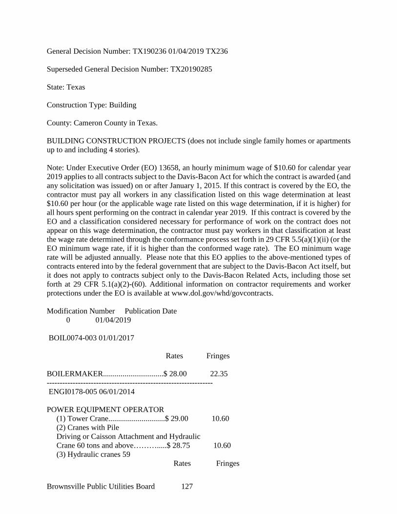
Brownsville Public Utilities Board 127
General Decision Number: TX190236 01/04/2019 TX236 Superseded General Decision Number: TX20190285 State: Texas Construction Type: Building County: Cameron County in Texas. BUILDING CONSTRUCTION PROJECTS (does not include single family homes or apartments up to and including 4 stories). Note: Under Executive Order (EO) 13658, an hourly minimum wage of $10.60 for calendar year 2019 applies to all contracts subject to the Davis-Bacon Act for which the contract is awarded (and any solicitation was issued) on or after January 1, 2015. If this contract is covered by the EO, the contractor must pay all workers in any classification listed on this wage determination at least $10.60 per hour (or the applicable wage rate listed on this wage determination, if it is higher) for all hours spent performing on the contract in calendar year 2019. If this contract is covered by the EO and a classification considered necessary for performance of work on the contract does not appear on this wage determination, the contractor must pay workers in that classification at least the wage rate determined through the conformance process set forth in 29 CFR 5.5(a)(1)(ii) (or the EO minimum wage rate, if it is higher than the conformed wage rate). The EO minimum wage rate will be adjusted annually. Please note that this EO applies to the above-mentioned types of contracts entered into by the federal government that are subject to the Davis-Bacon Act itself, but it does not apply to contracts subject only to the Davis-Bacon Related Acts, including those set forth at 29 CFR 5.1(a)(2)-(60). Additional information on contractor requirements and worker protections under the EO is available at www.dol.gov/whd/govcontracts. Modification Number Publication Date 0 01/04/2019 BOIL0074-003 01/01/2017 Rates Fringes BOILERMAKER...............................$ 28.00 22.35 ---------------------------------------------------------------- ENGI0178-005 06/01/2014 POWER EQUIPMENT OPERATOR (1) Tower Crane.............................$ 29.00 10.60 (2) Cranes with Pile Driving or Caisson Attachment and Hydraulic Crane 60 tons and above……….....$ 28.75 10.60 (3) Hydraulic cranes 59 Rates Fringes
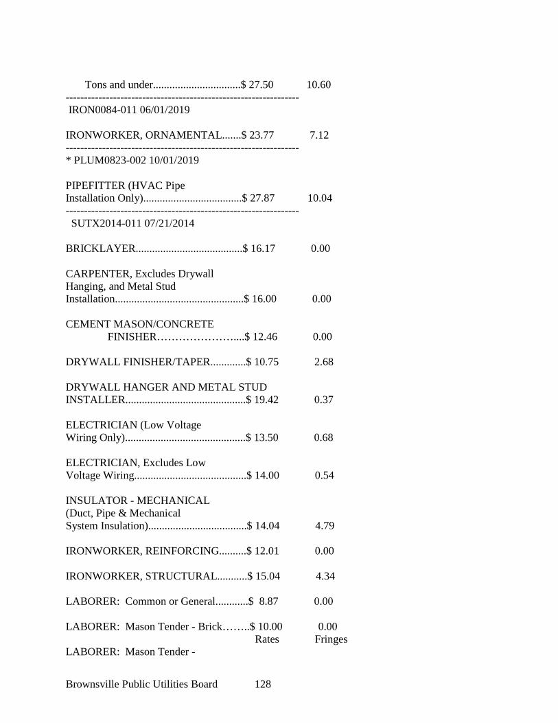
Brownsville Public Utilities Board 128
Tons and under................................$ 27.50 10.60 ---------------------------------------------------------------- IRON0084-011 06/01/2019 IRONWORKER, ORNAMENTAL.......$ 23.77 7.12 ---------------------------------------------------------------- * PLUM0823-002 10/01/2019 PIPEFITTER (HVAC Pipe Installation Only)....................................$ 27.87 10.04 ---------------------------------------------------------------- SUTX2014-011 07/21/2014 BRICKLAYER.......................................$ 16.17 0.00 CARPENTER, Excludes Drywall Hanging, and Metal Stud Installation...............................................$ 16.00 0.00 CEMENT MASON/CONCRETE FINISHER…………………....$ 12.46 0.00 DRYWALL FINISHER/TAPER.............$ 10.75 2.68 DRYWALL HANGER AND METAL STUD INSTALLER............................................$ 19.42 0.37 ELECTRICIAN (Low Voltage Wiring Only)............................................$ 13.50 0.68 ELECTRICIAN, Excludes Low Voltage Wiring.........................................$ 14.00 0.54 INSULATOR - MECHANICAL (Duct, Pipe & Mechanical System Insulation)....................................$ 14.04 4.79 IRONWORKER, REINFORCING..........$ 12.01 0.00 IRONWORKER, STRUCTURAL...........$ 15.04 4.34 LABORER: Common or General............$ 8.87 0.00 LABORER: Mason Tender - Brick……..$ 10.00 0.00 Rates Fringes LABORER: Mason Tender -
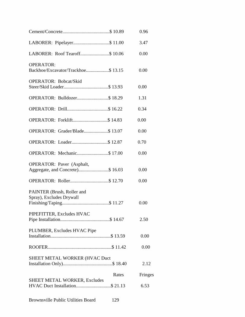
Brownsville Public Utilities Board 129
Cement/Concrete.......................................$ 10.89 0.96 LABORER: Pipelayer..............................$ 11.00 3.47 LABORER: Roof Tearoff........................$ 10.06 0.00 OPERATOR: Backhoe/Excavator/Trackhoe...................$ 13.15 0.00 OPERATOR: Bobcat/Skid Steer/Skid Loader.....................................$ 13.93 0.00 OPERATOR: Bulldozer..........................$ 18.29 1.31 OPERATOR: Drill..................................$ 16.22 0.34 OPERATOR: Forklift.............................$ 14.83 0.00 OPERATOR: Grader/Blade....................$ 13.07 0.00 OPERATOR: Loader..............................$ 12.87 0.70 OPERATOR: Mechanic..........................$ 17.00 0.00 OPERATOR: Paver (Asphalt, Aggregate, and Concrete).........................$ 16.03 0.00 OPERATOR: Roller................................$ 12.70 0.00 PAINTER (Brush, Roller and Spray), Excludes Drywall Finishing/Taping.......................................$ 11.27 0.00 PIPEFITTER, Excludes HVAC Pipe Installation.........................................$ 14.67 2.50 PLUMBER, Excludes HVAC Pipe Installation..................................................$ 13.59 0.00 ROOFER.....................................................$ 11.42 0.00 SHEET METAL WORKER (HVAC Duct Installation Only).........................................$ 18.40 2.12 Rates Fringes SHEET METAL WORKER, Excludes HVAC Duct Installation.............................$ 21.13 6.53
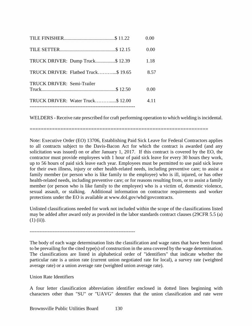
Brownsville Public Utilities Board 130
TILE FINISHER.........................................$ 11.22 0.00 TILE SETTER.............................................$ 12.15 0.00 TRUCK DRIVER: Dump Truck................$ 12.39 1.18 TRUCK DRIVER: Flatbed Truck………...$ 19.65 8.57 TRUCK DRIVER: Semi-Trailer Truck............................................................$ 12.50 0.00 TRUCK DRIVER: Water Truck……….....$ 12.00 4.11 ---------------------------------------------------------------- WELDERS - Receive rate prescribed for craft performing operation to which welding is incidental. ================================================================ Note: Executive Order (EO) 13706, Establishing Paid Sick Leave for Federal Contractors applies to all contracts subject to the Davis-Bacon Act for which the contract is awarded (and any solicitation was issued) on or after January 1, 2017. If this contract is covered by the EO, the contractor must provide employees with 1 hour of paid sick leave for every 30 hours they work, up to 56 hours of paid sick leave each year. Employees must be permitted to use paid sick leave for their own illness, injury or other health-related needs, including preventive care; to assist a family member (or person who is like family to the employee) who is ill, injured, or has other health-related needs, including preventive care; or for reasons resulting from, or to assist a family member (or person who is like family to the employee) who is a victim of, domestic violence, sexual assault, or stalking. Additional information on contractor requirements and worker protections under the EO is available at www.dol.gov/whd/govcontracts. Unlisted classifications needed for work not included within the scope of the classifications listed may be added after award only as provided in the labor standards contract clauses (29CFR 5.5 (a) (1) (ii)). ---------------------------------------------------------------- The body of each wage determination lists the classification and wage rates that have been found to be prevailing for the cited type(s) of construction in the area covered by the wage determination. The classifications are listed in alphabetical order of "identifiers" that indicate whether the particular rate is a union rate (current union negotiated rate for local), a survey rate (weighted average rate) or a union average rate (weighted union average rate). Union Rate Identifiers A four letter classification abbreviation identifier enclosed in dotted lines beginning with characters other than "SU" or "UAVG" denotes that the union classification and rate were
Brownsville Public Utilities Board 131
prevailing for that classification in the survey. Example: PLUM0198-005 07/01/2014. PLUM is an abbreviation identifier of the union which prevailed in the survey for this classification, which in this example would be Plumbers. 0198 indicates the local union number or district council number where applicable, i.e., Plumbers Local 0198. The next number, 005 in the example, is an internal number used in processing the wage determination. 07/01/2014 is the effective date of the most current negotiated rate, which in this example is July 1, 2014. Union prevailing wage rates are updated to reflect all rate changes in the collective bargaining agreement (CBA) governing this classification and rate. Survey Rate Identifiers Classifications listed under the "SU" identifier indicate that no one rate prevailed for this classification in the survey and the published rate is derived by computing a weighted average rate based on all the rates reported in the survey for that classification. As this weighted average rate includes all rates reported in the survey, it may include both union and non-union rates. Example: SULA2012-007 5/13/2014. SU indicates the rates are survey rates based on a weighted average calculation of rates and are not majority rates. LA indicates the State of Louisiana. 2012 is the year of survey on which these classifications and rates are based. The next number, 007 in the example, is an internal number used in producing the wage determination. 5/13/2014 indicates the survey completion date for the classifications and rates under that identifier. Survey wage rates are not updated and remain in effect until a new survey is conducted. Union Average Rate Identifiers Classification(s) listed under the UAVG identifier indicate that no single majority rate prevailed for those classifications; however, 100% of the data reported for the classifications was union data. EXAMPLE: UAVG-OH-0010 08/29/2014. UAVG indicates that the rate is a weighted union average rate. OH indicates the state. The next number, 0010 in the example, is an internal number used in producing the wage determination. 08/29/2014 indicates the survey completion date for the classifications and rates under that identifier. A UAVG rate will be updated once a year, usually in January of each year, to reflect a weighted average of the current negotiated/CBA rate of the union locals from which the rate is based. ---------------------------------------------------------------- WAGE DETERMINATION APPEALS PROCESS 1.) Has there been an initial decision in the matter? This can be: * an existing published wage determination * a survey underlying a wage determination * a Wage and Hour Division letter setting forth a position on a wage determination matter * a conformance (additional classification and rate) ruling
Brownsville Public Utilities Board 132
On survey related matters, initial contact, including requests for summaries of surveys, should be with the Wage and Hour Regional Office for the area in which the survey was conducted because those Regional Offices have responsibility for the Davis-Bacon survey program. If the response from this initial contact is not satisfactory, then the process described in 2.) and 3.) should be followed. With regard to any other matter not yet ripe for the formal process described here, initial contact should be with the Branch of Construction Wage Determinations. Write to: Branch of Construction Wage Determinations Wage and Hour Division U.S. Department of Labor 200 Constitution Avenue, N.W. Washington, DC 20210 2.) If the answer to the question in 1.) is yes, then an interested party (those affected by the action) can request review and reconsideration from the Wage and Hour Administrator (See 29 CFR Part 1.8 and 29 CFR Part 7). Write to: Wage and Hour Administrator U.S. Department of Labor 200 Constitution Avenue, N.W. Washington, DC 20210 The request should be accompanied by a full statement of the interested party's position and by any information (wage payment data, project description, area practice material, etc.) that the requestor considers relevant to the issue. 3.) If the decision of the Administrator is not favorable, an interested party may appeal directly to the Administrative Review Board (formerly the Wage Appeals Board). Write to: Administrative Review Board U.S. Department of Labor 200 Constitution Avenue, N.W. Washington, DC 20210 4.) All decisions by the Administrative Review Board are final. ================================================================ END OF GENERAL DECISION
Brownsville Public Utilities Board 133
BPUB TECHNICAL SPECIFICATIONS
Brownsville Public Utilities Board 134
THIS PAGE INTENTIONLY LEFT BLANK

CONTRACT CONSIDERATIONS 01019 - 1
SECTION 01019 CONTRACT CONSIDERATIONS
PART 1 - GENERAL 1.01 SECTION INCLUDES
A. Payment Procedures
B. Change Procedures
C. Measurement and Payment for Unit Prices
D. Correlation of CONTRACTOR Submittals
1.02 PAYMENT PROCEDURES A. Submit one (1) copy of the Application for Payment based upon Application for
Payment, or other proposed format as agreed upon by OWNER in advance of request.
B. Payment Period: at intervals stipulated in the Agreement.
C. Submit an updated Progress Schedule and Photographs with each Application for Payment in accordance with Section 01300 - Submittals.
D. Submit data justifying dollar amounts in question when ENGINEER requires substantiating information.
1.03 CHANGE PROCEDURES A. ENGINEER may advise of minor changes in the Work not involving an
adjustment to Contract Price or Contract Time as authorized by Paragraph 9.5 of the General Conditions.
B. ENGINEER may amend or supplement the Contract Documents as authorized by General Conditions by issuing a detailed description of a proposed change with supplementary or revised Drawings and Specifications, including a change in Contract Time related to the change (with a stipulation for any overtime work required) and the period of time during which the requested price will be considered valid. Prepare and submit an estimate within 15 days.
C. Propose a change by submitting request for change to ENGINEER and describe the proposed change and its full effect on the Work. Describe the reason for the change and the effect on the Contract Price and Contract Time with full documentation (and a statement describing the effect on Work by separate or other contractors). Document any requested substitutions In accordance with the Procurement General Conditions.
D. Stipulated Price Change Order: based on CONTRACTOR's maximum price quotation or CONTRACTOR's request for a Change Order as approved by ENGINEER.
CONTRACT CONSIDERATIONS 01019 - 2
E. Unit Price Change Order: for pre-determined unit prices and quantities and executed on a fixed unit price basis. Changes in Contract Price and Contract Time to be computed as specified for Time and Material Change Order.
F. Time and Material Change Order: based on itemized account and supporting data after completion of change within time limits indicated in the General Conditions. ENGINEER to determine the change allowable in Contract Price and Contract Time as provided in the General Conditions. Maintain detailed records of work done on this basis, provide full information required for evaluation of proposed changes, and substantiate costs for changes in the Work.
G. Change Order Form: based on Change Order Form, or other proposed format as agreed upon by OWNER in advance of request.
1.04 CORRELATION OF CONTRACTOR SUBMITTALS A. Promptly revise Progress Schedules to reflect any change in Contract Time and
revise sub-schedules to adjust time for other items of the Work affected by the change.
B. Promptly enter changes in Project Record Documents.
PART 2 - PRODUCTS - NOT USED
PART 3 - EXECUTION - NOT USED
END OF SECTION
MEASUREMENT AND PAYMENT
01025 - 1
SECTION 01025
MEASUREMENT AND PAYMENT
PART 1 - GENERAL
1.01 SECTION INCLUDES
A. Measurement and payment criteria applicable to the Work performed under a unit price
payment method.
B. Defect assessment and non-payment for rejected work.
1.02 AUTHORITY
A. This Section is the authority for measurement methods and definitions of pay items, and
supersedes any such direction which may be stated or implied in the Drawings or in
individual sections of the technical specifications (Divisions 2 and higher).
B. Take all measurements and compute quantities. The OWNER will verify measurements
and quantities.
C. Assist by providing necessary equipment, workers, and survey personnel as required.
1.03 UNIT QUANTITIES SPECIFIED
A. Quantities indicated in the Bid Proposal are for bidding and contract purposes only.
Quantities and measurements supplied or placed in the Work and verified by the OWNER
determine payment.
B. If the actual Work requires more or fewer quantities than those quantities indicated,
provide the required quantities at the unit sum/prices contracted.
1.04 MEASUREMENT OF QUANTITIES
A. Measurement by Volume: Measured by cubic dimension using mean length, width and
height or thickness.
B. Measurement by Area: Measured by square dimension using mean length and width or
radius.
C. Linear Measurement: Measured by linear dimension, at the item centerline or mean
chord.
D. Stipulated Sum/Price Measurement: Items measured by weight, volume, area,
1.05 PAYMENT
A. Payment Includes: Full compensation for all required labor, products, tools, equipment,
plant, transportation, services and incidentals; erection, application or installation of an
item of the Work, including overhead and profit.
B. Final payment for Work governed by unit prices will be made on the basis of the actual
measurements and quantities accepted by the OWNER multiplied by the unit sum/price
for Work which is incorporated in or made necessary by the Work.
MEASUREMENT AND PAYMENT
01025 - 2
1.06 DEFECT ASSESSMENT
A. Replace the Work, or portions of the Work, not conforming to specified requirements.
B. The individual specification sections may modify these options or may identify a specific
formula or percentage sum/price reduction for defective Work.
C. The authority of the OWNER to assess the defect and identify payment adjustment, is
final.
1.07 NON-PAYMENT FOR REJECTED PRODUCTS
A. Payment will not be made for any of the following:
1. Products wasted or disposed of in a manner that is not acceptable.
2. Products determined as unacceptable before or after placement.
3. Products not completely unloaded from the transporting vehicle.
4. Products placed beyond the lines and levels of the required Work.
5. Products remaining on hand after completion of the Work.
6. Loading, hauling and disposing of rejected Products.
1.08 STANDARDS FOR COMPUTING PAY ITEMS
A. See the General Conditions, particularly paragraphs 2.6.3, 2.9, and 14.1, for additional
direction regarding use and application of pay items.
B. The intent of Pay Items is to address all items shown, specified, required, reasonably
implied, or otherwise necessary for the completion of the Work indicated in the Contract
Documents. No separate payment will be made for costs (including, but not necessarily
limited to labor, equipment, materials, or other CONTRACTOR expenses) arising from
the completion of the Work which was indicated in the Contract Documents, whether or
not a Pay Item expressly includes such costs. Should the Work include costs not expressly
included in any Pay Item, CONTRACTOR is presumed to have included such costs in
his bid under related pay items.
1. Other Pay Items not specifically listed in the Pay Item Descriptions below, which are
for specific work (such as decommissioning or demolition of an existing facility),
may be identified in the Bid Form. These items are provided in order to establish a
basis for payment upon completion of work including and related to that described
for the Pay Item in the Bid Form.
Should the Work include costs not expressly or impliedly included under any Pay
Item, CONTRACTOR is presumed to have included such costs in his bid under the
Pay Item entitled "ALL OTHER WORK".
2. ALL OTHER WORK - Lump Sum Price shall include all work indicated in the
Contract Documents (including, but not necessarily limited to labor, equipment,
materials, or other CONTRACTOR expenses arising from the completion of the
Work) which the CONTRACTOR deems to be expressly and impliedly omitted from,
and unrelated to, other Pay Items listed in the Bid Form.
MEASUREMENT AND PAYMENT
01025 - 3
PART 2 - PRODUCTS - NOT USED
PART 3 - EXECUTION - NOT USED
END OF SECTION

MEASUREMENT AND PAYMENT
01025 - 4
THIS PAGE INTENTIONALLY LEFT BLANK
COORDINATION AND MEETINGS 01039 - 1
SECTION 01039 COORDINATION AND MEETINGS
PART 1 - GENERAL 1.01 SECTION INCLUDES
A. Coordination.
B. Preconstruction Conference.
C. Site Mobilization Meeting.
D. Progress Meetings.
E. Preinstallation Conference.
F. Field Engineering.
1.02 COORDINATION A. Inform OWNER and ENGINEER of the address for sending to which official
correspondence and the address and telephone number of CONTRACTOR's representative who will be Project Manager for the Contract and responsible and available outside of normal working hours for emergency repairs and maintenance of safety devices.
B. During periods of construction and testing keep OWNER and ENGINEER informed in writing with name, address, and telephone number of CONTRACTOR's representative who will be responsible and available outside of normal working hours for emergency repairs and the maintenance of safety devices.
C. Identify correspondence, drawings, data and materials, packing slips or other items associated with this Contract as that identified on the Cover.
D. Coordinate scheduling, submittals, and Work for the various Sections of Specifications to effectuate an efficient and orderly sequence for installing interdependent construction elements, with provisions for accommodating items installed later.
E. Coordinate Work of various Sections with interdependent responsibilities for installing, connecting to, and placing in service, operating equipment.
F. Coordinate space requirements and installation of mechanical and electrical work, which are indicated by diagram on Drawings. Follow routing shown for pipes, ducts, and conduit, as closely as practicable; place runs parallel with line of building. Utilize spaces efficiently to maximize accessibility for other installations, maintenance, and repairs.
G. In finished areas (except as otherwise indicated), conceal pipes, ducts, and wiring within the construction. Coordinate locations of fixtures and outlets with finish elements.
COORDINATION AND MEETINGS 01039 - 2
H. Coordinate completion and clean up of Work of separate sections in preparation for Substantial Completion and for portions of Work designated for OWNER's partial occupancy.
I. After OWNER occupancy of premises, coordinate access to site for correction of defective Work and/or incomplete Work to minimize disruption of OWNER's activities.
J. Provide coordination in accordance with Article 7 of the General Conditions.
1.03 PRECONSTRUCTION CONFERENCE A. OWNER to schedule a preconstruction conference in accordance with General
Conditions Article 2.
B. Agenda: 1. Distribute Contract Documents. 2. Finalize preliminary Progress Schedule, submittal schedule and schedule of
values. 3. Designate personnel representing each party. 4. Procedures and processing of field decisions, submittals, substitutions,
applications for payments, proposal request, testing, Change Orders and Contract closeout procedures.
5. Scheduling.
1.04 SITE MOBILIZATION MEETING (NOT USED) A. OWNER to schedule a meeting at the Project site before CONTRACTOR
occupancy.
B. Attendance Required: OWNER, *ENGINEER, * *Special Consultants, * CONTRACTOR, *CONTRACTOR's Superintendent, * and major Sub CONTRACTORs.
C. Agenda: 1. Use of premises by OWNER and CONTRACTOR. 2. OWNER's requirements *and *partial* occupancy*. 3. Construction facilities and controls provided by OWNER. 4. Temporary utilities provided by OWNER. 5. Survey and *building* * * layout. 6. Security and housekeeping procedures. 7. Schedules. 8. Procedures for testing. 9. Procedures for maintaining record documents. 10. Requirements for start-up of equipment. 11. Inspection and acceptance of equipment put into service during construction
period.
COORDINATION AND MEETINGS 01039 - 3
1.05 PROGRESS MEETINGS A. OWNER to schedule a progress meeting no later than 60 days after the
Preconstruction Conference and a monthly meeting throughout progress of the Work. Make arrangements for meetings, prepare agenda with copies for participants, and preside at meetings.
B. Attendance: CONTRACTOR, major Subcontractors, OWNER, and ENGINEER, as appropriate to agenda topics for each meeting.
C. Agenda: 1. Review minutes of previous meetings. 2. Unresolved issues. 3. Review Work progress. 4. Observations, problems, and decisions. 5. Identification of problems that impede planned progress. 6. Review of submittals schedule and status of submittals. 7. Review of off-site fabrication and delivery schedules. 8. Maintenance of progress schedule. 9. Corrective measures to regain projected schedules. 10. Planned progress during succeeding Work period. 11. Coordination of projected progress. 12. Maintenance of quality and work standards. 13. . Effect of proposed changes on progress schedule and coordination. 14. Other business relating to Work.
1.06 PREINSTALLATION CONFERENCE A. When required in individual Specification Section, convene a preinstallation
conference at work site before commencing Work of the Section.
B. Require attendance of parties directly affecting, or affected by, work of the specific Section. Notify ENGINEER 5 days in advance of meeting date.
C. Make arrangements for meeting and preside at conference.
D. Review conditions of installation, preparation and installation procedures, and coordination with related work.
PART 2 - PRODUCTS - NOT USED
PART 3 - EXECUTION 3.01 FIELD ENGINEERING
A. Surveying: All surveying shall be performed by a Land Surveyor registered in the State of Texas. 1. Existence and location of underground and other utilities and construction
indicated as existing are not guaranteed. Before beginning site work, investigate and verify the existence and location of underground utilities and other utilities and construction. Use "One-Call," l-800-DIG-TESS or (800) 344-8377.
COORDINATION AND MEETINGS 01039 - 4
2. Furnish all surveys necessary to perform the Work. Maintain surveyor's log of control and other survey work. Keep log available for reference.
3. Verify layout information shown on the Drawings in relation to existing benchmarks before laying out of the Work. Locate and protect existing benchmarks and control points. Preserve permanent reference points during construction.
4. Promptly report lost or destroyed reference points, benchmarks, or control points. Promptly report requirements relocate reference and control points due to changes in grades. Promptly replace lost or destroyed control points based on the original survey control points.
END OF SECTION
SUBMITTALS 01300 - 1
SECTION 01300 SUBMITTALS
PART 1 - GENERAL 1.01 SECTION INCLUDES
A. Submittal procedures for: 1. Schedule of Values. 2. Construction Schedules. 3. Shop Drawings, Product Data, and Samples 4. Operations and Maintenance Data. 5. Manufacturer's Certificates. 6. Construction Photographs. 7. Project Record Documents. 8. Video Tapes. 9. Design Mixes.
1.02 SUBMITTAL PROCEDURES A. Scheduling and Handling:
1. Schedule submittals well in advance of the need for the material or equipment for construction. Allow time to make delivery of material or equipment after submittal has been approved.
2. Develop a submittal schedule that allows sufficient time for initial review, correction, resubmission and final review of all submittals. The Engineer will review and return submittals to the Contractor as expeditiously as possible but the amount of time required for review will vary depending on the complexity and quantity of data submitted. In no case will a submittal schedule be acceptable which allows less than 30 days for initial review by the Engineer. This time for review shall in no way be justification for delays or additional compensation to the Contractor. Recognizing that time is of the essence, the Contractor is to stamp the top of each submittal with the words ROUTINE or CRITICAL. Routine submittals shall be processed in accordance with the timeframe set forth previously. Critical submittals are those that: were overlooked by the Contractor, involve complex coordination, or are crucial to the successful completion of a specific portion of the project. For critical submittals: a. Contractor shall indicate on the submittal his realistically estimated date of
when a review must be returned; b. Upon return of critical submittals, Contractor shall date-stamp the
transmittal page with date and time received; c. Contractor is cautioned that the use of critical submittals is not a substitute
for proper due diligence on his part. Review of critical submittals found to be routine shall be accompanied by an invoice for excess time and material expenditures that were required in order to complete the critical review as compared to a routine review. The Resident Project Representative shall
SUBMITTALS 01300 - 2
make the determination as to whether a critical submittal was in fact routine.
3. The Engineer's review of submittals covers only general conformity to the Drawings, Specifications and dimensions which affect the layout. The Contractor is responsible for quantity determination. Quantities may be verified by the Engineer. The Contractor is responsible for any errors, omissions or deviations from the Contract requirements; review of submittals in no way relieves the Contractor from his obligation to furnish required items according to the Drawings and Specifications.
4. Submit sufficient copies of documents. Unless otherwise specified in the following paragraphs or in the Specifications, provide 3 copies in addition to the number the Contractor requires returned. For portions of the project involving electrical or signal components, provide one additional copy (4 copies in addition to the number the Contractor requires returned).
5. Revise and resubmit submittals as required. Identify all changes made since previous submittal.
6. A maximum of three (3) reviews will be conducted on any one submittal. Submittals requiring more than three (3) reviews will be considered inadequate and result in a recovery of review expenses from the Contractor.
7. The Contractor shall assume the risk for material or equipment which is fabricated or delivered prior to approval. No material or equipment shall be incorporated into the Work or included in periodic progress payments until approval has been obtained in the specified manner.
B. Transmittal Form and Numbering: 1. Transmit each submittal to the Engineer with a Transmittal Cover. 2. Sequentially number each transmittal including the Specification Section
number followed by a area designation number and the sequential number beginning with the number 1. Re-submittals shall use the original number with an alphabetic suffix (i.e., 2A for first re-submittal of Submittal 2 or 15C for third re-submittal of Submittal 15). Each submittal shall only contain one type of work, material, or equipment. Mixed submittals will not be accepted.
3. Identify time nature of submittal, either ROUTINE or CRITICAL. 4. Identify variations from requirements of Contract Documents and identify
product or system limitations. 5. For submittal numbering of video tapes, see paragraph 1.10 Video.
C. Transmittal Cover: 1. Transmittal Cover, certifying that the items have been reviewed in detail and
are correct and in accordance with Contract Documents, except as noted by any requested variance. A stamp may be used to print the information on the Transmittal Cover except for the Contractor’s signature. Regardless of whether the transmittal cover is typed or stamped, the transmittal cover text shall be a minimum of fourteen (14) point.
2. As a minimum, Transmittal Cover information shall include: a. Contractor's name. b. Job number. c. Submittal number.
SUBMITTALS 01300 - 3
d. Certification statement that the Contractor has reviewed the submittal and it is in compliance with the Contract Documents.
e. Signature line for Contractor. f. Submittal type – routine or critical
3. The bottom half of the Transmittal Cover shall be kept blank.
D. Electronic copy submittals: 1. Electronic copies of the approved paper copy Operation and Maintenance
Manuals are to be produced in Adobe Acrobat's Portable Document Format (PDF) Version 9.0 or higher.
2. Do not password protect and/or lock the PDF document. 3. Create one (1) PDF document (PDF file) for each equipment O&M Manual. 4. Drawings or other graphics must be converted to PDF format and made part
of the one (1) PDF document. a. Scanning to be used only where actual file conversion is not possible.
5. Rotate pages that must be viewed in landscape to the appropriate position for easy reading.
6. Images only shall be scanned at a resolution of 300 dpi or greater. a. Perform Optical Character Recognition (OCR) capture on all images. b. Achieve OCR with the "original image with hidden text" option. c. Word searches of the PDF document must operate successfully to
demonstrate OCR compliance. 7. Create bookmarks in the navigation frame, for each entry in the Table of
Contents/Index. a. Normally three (3) levels deep (i.e., "Chapter," "Section," "Sub-section").
8. Thumbnails must be generated for each PDF file. 9. Set the opening view for PDF files as follows:
a. Initial view: Bookmarks and Page. b. Magnification: Fit in Window. c. Page layout: Single page. d. Set the file to open to the cover page of the manual with bookmarks to the
left, and the first bookmark linked to the cover page. e. All PDF documents shall be set with the option "Fast Web View" 1 to open
the first 2 pages of the document for the viewer while the rest of the document continues to load.
f. File naming conventions: 1) File names shall use a "ten dot three" convention (XXXXX-YYYY-
Z.PDF) where XXXXX is the Specification Section number, YYYY is the area designation number and Z is the sequential submittal number.
10. Labeling: a. As a minimum, include the following labeling on all CD-ROM discs and
jewel 19 cases: 1) Project Name. 2) Equipment Name and Project Tag Number. 3) Project Specification Section. 4) Manufacturer Name. 5) Vendor Name.
SUBMITTALS 01300 - 4
11. Binding: a. Include labeled CD(s) in labeled jewel case(s). Bind jewel cases in standard
three-ring binder Jewel Case Page(s), inserted at the front of the Final paper copy submittal.
b. Jewel Case Page(s) to have means for securing Jewel Case(s) to prevent loss (e.g., flap and strap).
1.03 CONSTRUCTION SCHEDULE A. Submit Construction Schedules in accordance with Section 01325 – Construction
Schedule.
1.04 OPERATIONS AND MAINTENANCE DATA A. Submit Operations and Maintenance data in accordance with Section 01782 -
Operations and Maintenance Data.
1.05 MANUFACTURER'S CERTIFICATES A. When required in Specification sections, submit manufacturers' certificate of
compliance for review by Engineer.
B. Transmittal Cover, as described in paragraph 1.02C, shall be placed on front page of the certification.
C. Submit supporting reference data, affidavits, and certifications as appropriate.
D. Certificates may be recent or previous test results on material or product, but must be acceptable to Engineer.
1.06 CONSTRUCTION PHOTOGRAPHS A. Submit Construction Photographs in accordance with Section 01321 –
Construction Photographs.
1.07 PROJECT RECORD DOCUMENTS A. Submit Project Record Documents in accordance with Section 01785 - Project
Record Documents.
1.08 VIDEO A. Submit television video tapes as required for Acceptance Testing for Sanitary
Sewers.
B. Transmittal forms for video tapes shall be numbered sequentially beginning with TV01, TV02, etc.
1.09 DESIGN MIXES A. When specified in Specifications, submit design mixes for review.
B. Transmittal Cover, as described in paragraph 1.02C, shall be placed on front page of each design mix.
C. Mark each design mix to identify proportions, gradations, and additives for each class and type of design mix submitted. Include applicable test results on samples for each mix.
SUBMITTALS 01300 - 5
D. Maintain a copy of approved design mixes at mixing plant.
PART 2 - PRODUCTS - NOT USED
PART 3 - EXECUTION 3.01 GENERAL
A. Submittals made as part of this project will become a vital portion of the project record and will be referenced by the Owner for the useful life of the project. All submittals shall be of high quality. To this end, the following requirements are made: 1. As much as possible, all catalog cuts and manufacturer’s information shall be
original. 2. Copies, when required, shall be clean and entirely legible. 3. Neither facsimiles nor copies of facsimiles are to be included as part of any
submittal. 4. Binders, if used, shall be rugged, lock-ring type. Spine of binders shall be
clearly labeled with the information outlined in items 1.02 C.2.a. through c.
B. Reviewed submittals shall be returned to Contractor for distribution to subcontractors and other trades as required. As a minimum, submittals returned to the Contractor will be marked with review comments indicating findings of the review and giving instruction as to necessity of a re-submittal. The Engineer may, at his option, use a stamp for this purpose. Detailed correspondence covering the review may also accompany returned submittals.
END OF SECTION
SUBMITTALS 01300 - 6
THIS PAGE INTENTIONALLY LEFT BLANK
CONSTRUCTION SCHEDULE 01325 - 1
SECTION 01325 CONSTRUCTION SCHEDULE
PART 1 - PART 1 GENERAL 1.01 GENERAL
A. Provide Construction Schedules for Work included in this Contract in accordance with requirements in this Section. Create a Construction Schedule using Critical Path Method (CPM) computer software capable of mathematical analysis of Precedence Diagramming Method (PDM) schedules. Provide printed activity listings and bar charts in formats described in this Section.
B. Combine activity listings and bar charts with a narrative report to form the Contractor's Construction Schedule submittal for the Engineer.
1.02 SCHEDULING STAFF A. Employ or retain services of an individual experienced in critical path scheduling
for the duration of the Contract. This person shall cooperate with the Engineer and shall update the Contractor's schedule at least monthly as required to indicate current status of the Work.
1.03 SUBMITTALS A. Make Construction Schedule submittals for review by the Engineer in accordance
with requirements of the Conditions of the Contract.
B. During the pre-construction meeting provide sample bar charts and activity listings produced from the scheduling software proposed. Scheduling software is subject to approval of the Engineer and must meet requirements provided in this Section. Review of the samples will be provided by the Engineer within 7 days of the submittal.
C. Within 21 days of receipt of approval of the Contractor's format, or 30 days of the Notice to Proceed, whichever is later, submit a proposed Construction Schedule for review. The Construction Schedule submittal shall be based on the following: 1. The level of detail and number of activities required in the schedule are
dependent on the project type. a. For wastewater projects, the work shall be categorized by Work Type and
Area Code in the schedule. 2. For projects with multiple types of tasks within the scope, these types of work
shall be indicated separately within the schedule. 3. For projects with work at different physical locations or service areas, or
different facilities within a site, each location or facility shall be indicated separately within the schedule. Work on each floor of a multi-story building shall be shown as separate tasks.
4. For projects with multiple crafts or significant subcontractor components, these elements shall be indicated separately within the schedule. Unless permitted by the Engineer, tasks shall consist of work covered by only one
CONSTRUCTION SCHEDULE 01325 - 2
division of the Project Manual. 5. Unless permitted by the Engineer, each schedule task shall be the same as a
schedule of values line item, and vice versa. 6. For projects with significant major equipment items or materials representing
over 5 percent of the Total Contract Price, the schedule shall indicate dates when these items are to be purchased, when they are to be delivered, and when installed. Activities for testing, adjustment, and delivering O & M manuals shall be included.
7. No task except the acquisition of major equipment items shall represent more than one percent of the Total Contract Price for facility projects and 3 percent of the Total Contract Price for other projects. The duration of tasks may not exceed 40 calendar days.
8. For projects where operating facilities are involved, each period of work which will impact any process or operation shall be identified in the schedule and must be agreed to by the Engineer and the facility operator prior to starting work in the area.
9. Construction Schedule submittals shall include: a. Printed bar charts which meet the criteria outlined in this Section and
which are produced by the Contractor's approved scheduling software. b. Activity listings which meet the criteria outlined in this Section and which
are produced by the Contractor's approved scheduling software. c. Predecessor/successor listing sorted by Activity ID which meets the criteria
outlined in this Section and which is produced by the Contractor's approved scheduling software.
d. A logic network diagram shall be required with the first construction schedule submittal for facilities projects.
e. A graphic or tabular display of estimated monthly billings for the Work shall be prepared and submitted by the Contractor with the first schedule submittal. This information is not required in monthly updates, unless significant changes in work require re-submittal of the schedule for review. The display shall allocate units indicated in the bid schedule or the schedule of values to Construction Schedule activities. (Weighted allocations are acceptable, where appropriate). The dollar value associated with each allocated unit will be spread across the duration of the activity on a monthly basis. The total for each month and a cumulative total will be indicated. These monthly forecasts are only for planning purposes of the Engineer. Monthly payments for actual work completed will be made by the Engineer in accordance with the Conditions of the Contract.
f. A narrative report which shall provide the information outlined in this Section.
D. No payment will be made until the Construction Schedule and billing forecast are accepted by the Engineer.
CONSTRUCTION SCHEDULE 01325 - 3
E. If the Contractor desires to make changes in his method of operating and scheduling, after approval of the original schedule has been given by the Engineer, the Contractor shall notify the Engineer in writing, stating the reasons for the change. If the Engineer considers these changes to be of significant nature, the Contractor may be required to revise and resubmit for approval all or the affected portion of the Contractor's Construction Schedule to show the effect on the Work.
F. Upon written request from the Engineer, the Contractor shall revise and submit for approval all or any part of the Construction Schedule submittal to reflect changed conditions in the Work or deviations made from the original plan and schedule.
G. The Contractor's Construction Schedule shall thereafter be updated with Actual Start and Actual Finish Dates, Percent Complete, and Remaining Duration of each Activity and submitted monthly. The data date to be used in updating the monthly Construction Schedule shall be the same data date as is used in the monthly Application for Payment. This monthly update of the schedule shall be required before the monthly Application for Payment will be processed for payment.
1.04 SCHEDULING COMPUTER SOFTWARE REQUIREMENTS A. The Contractor's Construction Schedule shall be created using CPM computer
software which provides mathematical analysis of PDM schedules. The software shall be capable of creating bar charts and activity listings which can be sorted by various fields, i.e., Sort by Activity ID; Sort by Early Start; Sort by Total Float; Sort by Area Code; sort by specification section number; and sort by Subcontractor. The software shall be capable of producing a logic network diagram.
B. The PDM scheduling software shall be capable of producing activity listings and bar charts with the following information for each activity in the schedule: 1. Activity ID 2. Activity Description 3. Estimated (Original) Duration 4. Remaining Duration 5. Actual Duration 6. Early Start Date 7. Late Start Date 8. Early Finish Date 9. Late Finish Date 10. Free Float 11. Total Float 12. Activity Codes (such as Area Code, Work Type, Specification Section,
Subcontractor)
C. The PDM scheduling software shall be capable of printing calendars using the mathematical analysis of the schedule, indicating the Contractor's standard work days of the week and scheduled holidays.
CONSTRUCTION SCHEDULE 01325 - 4
D. Scheduling software shall be capable of printing an activity listing which indicates the Predecessors and Successors, Lag Factors and Lag Relationships used in creating the logic of the schedule.
E. Scheduling software shall be capable of printing a bar chart of the entire schedule for the Work included in this Contract. The bar chart format shall provide a monthly time scale and shall be such that a 12-month time scale shall not exceed one page width. Bar charts may be printed or plotted on 8.5" x 11", 8.5" x 14" or 11" x 17" sheet sizes. Over-size plots are not acceptable.
1.05 NARRATIVE SCHEDULE REPORT A. The Narrative Report shall include a listing of the Activities Started This Month;
Activities Completed This Month; Activities Continued This Month; Activities Scheduled to Start or Complete Next Month; Problems Encountered This Month; Actions Taken to Solve These Problems.
B. The narrative Schedule Report shall include a description of changes made to the Construction Schedule Logic (i.e., changes in Predecessors and Lags); Activities Added to the Schedule; Activities Deleted from the Schedule; any other changes made to the Schedule other than the addition of Actual Start Dates and Actual Finish Dates and changes of Data Date and Remaining Durations for re-calculation of mathematical analysis.
PART 2 - PRODUCTS - NOT USED
PART 3 - EXECUTION - NOT USED
END OF SECTION
LABORATORY AND INSPECTION SERVICES 01460 - 1
SECTION 01460 LABORATORY AND INSPECTION SERVICES
PART 1 - GENERAL 1.01 GENERAL DESCRIPTION OF WORK:
A. This item shall consist of all required testing and inspection services required to provide certification that the completed construction is in substantial compliance with the contract, plans and specifications.
B. Testing and inspections shall include: all underground utilities (water, sewer & drainage), roadway embankment, subgrade, base & asphalt, curbs of all types, concrete pavements, concrete structures, signage, striping, and all other facilities as may be included in the overall scope of construction.
C. Inspections may include observations to determine compliance with the prescribed stormwater pollution prevention plan (SW3P), trench safety, personal protection equipment and traffic control plans.
D. The ENGINEER has the authority to observe, test, inspect, approve, and accept the work. The ENGINEER decides all questions about the quality and acceptability of materials, work performed, work progress, Contract interpretations, and acceptable Contract fulfillment. The ENGINEER has the authority to enforce and make effective these decisions.
E. The ENGINEER acts as a referee in all questions arising under the terms of the Contract. The ENGINEER’s decisions will be final and binding.
1.02 MEASUREMENT AND PAYMENT A. Measurement:
1. This work shall be considered incidental to the completion of the project and no additional compensation shall be paid for this work.
B. Payment 1. No separate payment shall be made for this item.
1.03 LABORATORY REPORTS A. The testing laboratory shall provide and distribute copies of laboratory reports to the
distribution list provided by the Engineer.
B. One copy of each laboratory report distributed or faxed to the Contractor shall be kept at the site field office for the duration of the project.
C. Before close of business on the working day following test completion and review, reports which indicate failing test results shall be transmitted immediately via fax from the testing laboratory to the material supplier, Contractor, Engineer and Resident Project Representative.
LABORATORY AND INSPECTION SERVICES 01460 - 2
1.04 LIMITS ON TESTING LABORATORY AUTHORITY A. Laboratory may not release, revoke, alter, or enlarge on requirements of Contract
Documents.
B. Laboratory may not approve or accept any portion of the Work.
C. Laboratory may not assume any duties of the Contractor.
D. Laboratory has no authority to stop the Work
1.05 CONTRACTOR RESPONSIBILITIES A. Provide safe access to the Work and to manufacturer's facilities for the Engineer, Resident
Project Representative and for testing laboratory personnel.
B. Provide to the testing laboratory a copy of the construction schedule and a copy of each update to the construction schedule.
C. Notify the Engineer and the testing laboratory during normal working hours of the day previous to the expected time for operations requiring inspection and testing services. If the Contractor fails to make timely prior notification, then the Contractor shall not proceed with the operations requiring inspection and testing services.
D. Request and monitor testing as required to provide timely results and to avoid delay to the Work. Provide samples to the laboratory in sufficient time to allow the required test to be performed in accordance with specified test methods before the intended use of the material.
E. Cooperate with laboratory personnel in collecting samples on site. Provide incidental labor and facilities for safe access to the Work to be tested; to obtain and handle samples at the site or at source of products to be tested; and to facilitate tests and inspections including storage and curing of test samples.
PART 2 - PRODUCTS (NOT USED)
PART 3 - EXECUTION 3.01 LABORATORY TESTING
A. All required laboratory testing shall be completed by an independent, qualified testing laboratory approved by the OWNER. All initial testing shall be paid for by the OWNER. Any retesting required shall be paid for by the CONTRACTOR.
B. Laboratory sampling and testing specified in individual Specification sections shall conform to the latest issues of ASTM standards, TxDOT methods, or other recognized test standards as approved by the Engineer.
C. The requirements of this section shall also apply to those tests for approval of materials, for mix designs, and for quality control of materials as performed by the testing laboratories employed by the Owner.
LABORATORY AND INSPECTION SERVICES 01460 - 3
D. Cost for additional review time will be billed to the CONTRACTOR by the OWNER for the actual hours required for the re-testing in accordance with the current rates as established by the contract between the OWNER and the Testing Lab. Cost for the additional review shall be paid to the OWNER by the CONTRACTOR on a monthly basis.
3.02 INSPECTIONS A. PROVIDERS: All required inspections shall be provided by either the independent
testing laboratory or by the Engineer. All initial inspections conducted during normal business hours (8:00 am to 5:00 pm, Monday – Friday, excluding Holidays) shall be provided by the OWNER at no charge. Any inspections or testing requested by the CONTRACTOR to be provided at any other time will be paid for by the CONTRACTOR. Any re-inspections or re-testing required shall be paid for by the CONTRACTOR.
B. COSTS: Cost for additional review time will be billed to the CONTRACTOR by the OWNER for the actual hours required for the retesting in accordance with the current rates as established by the contract between the OWNER and the Testing Lab. Cost for the additional review shall be paid to the OWNER by the CONTRACTOR on a monthly basis.
C. INSPECTORS: Inspectors are authorized representatives of the ENGINEER. Inspectors are authorized to examine all work performed and materials furnished, including preparation, fabrication, and material manufacture. Inspectors inform the CONTRACTOR of failures to meet Contract requirements. Inspectors may reject work or materials and may suspend work until any issues can be referred to and decided by the ENGINEER. Inspectors cannot alter, add, or waive Contract provisions, issue instructions contrary to the Contract, act as foremen for the CONTRACTOR, or interfere with the management of the work. Inspection or lack of inspection will not relieve the CONTRACTOR from obligation to provide materials or perform the work in accordance with the Contract. CONTRACTOR shall provide safe access to all parts of the work and provide information and assistance to the ENGINEER to allow a complete and detailed inspection and give the ENGINEER sufficient notice to inspect the work. Work performed without suitable inspection, as determined by the ENGINEER, may be ordered removed and replaced at CONTRACTOR’s expense. CONTRACTOR shall remove or uncover portions of finished work as directed. Once inspected, restore work to Contract requirements. If the uncovered work is acceptable, the costs to uncover, remove, and replace or make good the parts removed will be paid for in accordance “Changes in the Work.” If the work is unacceptable, CONTRACTOR shall assume all costs associated with repair or replacement, including the costs to uncover, remove, and replace or make good the parts removed. When a government entity, utility, Railroad Company, or other entity accepts or pays a portion of the Contract, that organization’s representatives may inspect the work but cannot direct the CONTRACTOR. The right of inspection does not make that entity a party to the Contract and does not interfere with the rights of the parties to the Contract.
LABORATORY AND INSPECTION SERVICES 01460 - 4
D. FINAL INSPECTION: After all work is complete, the CONTRACTOR will request a final inspection by the ENGINEER authorized to accept the work. The final inspection will be made as soon as possible, and not later than 5 calendar days after the request. No working day charges will be made between the date of request and final inspection. After the final inspection, if the work is satisfactory, the ENGINEER will notify the CONTRACTOR in writing of the final acceptance of the work. If the final inspection finds any work to be unsatisfactory, the ENGINEER will identify in writing all deficiencies in the work requiring correction. Correct the deficiencies identified. Working day charges will resume if these deficiencies are not corrected within 7 calendar days, unless otherwise authorized by the ENGINEER. Upon correction, the ENGINEER will make an inspection to verify that all deficiencies were corrected satisfactorily. The ENGINEER will provide written notice of the final acceptance.
3.03 SCHEDULING A. It shall be the CONTRACTOR’S responsibility to contact either the testing lab or the
Brownsville Public Utilities Engineering staff at least 48 hours before the required testing or inspection is to occur.
B. It shall be the CONTRACTOR’S responsibility to plan the construction in such a manner to allow the appropriate tests and inspections to be conducted without disruption to the construction process.
3.04 PREPARATION A. CONTRACTOR shall be responsible for preparing the project site as necessary to
conduct all required testing. This shall include, but may not be limited to: proper grading of construction site, completion of required compaction activities, complete installation of all forms, installation of all required reference points (grade stakes), provision of adequate traffic control, additional personnel and/or supplies and all necessary safety measures (i.e. OSHA compliant Trench Safety) as needed.
END OF SECTION
TEMPORARY FACILITIES 01500 - 1
SECTION 01500 TEMPORARY FACILITIES
PART 1 - GENERAL 1.01 RELATED DOCUMENTS:
A. Drawings and General provisions of Contract, including General Conditions and Supplementary General Conditions, and Division 1 requirements.
PART 2 - PRODUCTS (NOT USED) PART 3 - EXECUTION 3.01 OFFICE AT THE WORK SITE
A. During the performance of this Contract, CONTRACTOR shall maintain a suitable office at or near the site of the Work which shall be the headquarters of his superintendent. Any communication given to the superintendent or delivered to CONTRACTOR's office at the site of the Work in his absence shall be deemed to have been delivered to CONTRACTOR.
B. In addition, CONTRACTOR shall provide a suitable field office with at least 200 square feet of floor space, either adjacent to, or partitioned off from, his office at the site for use by OWNER's Representative. The office shall be provided with outside entrance door with a substantial lock, glazed windows suitable for light and ventilation, and adequate heating, air conditioning, and lighting facilities. CONTRACTOR shall pay all electricity and heating bills and shall provide telephone services with a telephone as specified hereinafter. The office shall be furnished with a desk, two four-drawer filing cabinets, a table, two chairs, a plan rack, and a locker for storage of surveying instruments. The doors on the locker shall be equipped for padlocking. The general arrangement of the office and facilities provided shall be acceptable to OWNER's Representative.
3.02 WATER FOR CONSTRUCTION A. All water required for and in connection with the Work to be performed shall be furnished
by and at the expense of the CONTRACTOR through meters installed on hydrants. CONTRACTOR shall supply all necessary tools, hose and pipe, and shall make necessary arrangements for securing and transporting such water and shall take water in such a manner, and at such times, that will not produce a harmful drain or decrease of pressure in the OWNER's water system. It shall be the CONTRACTOR's responsibility to make arrangements with the BPUB for the metering and reporting of the amount of water used. Water shall not be used in a wasteful manner. Standard hydrant wrenches shall be used for opening and closing of fire hydrants. In no case shall pipe wrenches be used for this purpose. Temporary lines shall be removed when no longer required.
3.03 TELEPHONE SERVICE A. CONTRACTOR shall make all necessary arrangements and pay all installation charges
for telephone lines in his offices at the site and shall provide all telephone instruments.
TEMPORARY FACILITIES 01500 - 2
3.04 SANITARY FACILITIES A. CONTRACTOR shall furnish temporary sanitary facilities at the site, as provided herein,
for the needs of all construction workers and others performing Work or furnishing services on the Project.
B. Sanitary facilities shall be of reasonable capacity, properly maintained throughout the construction period, and obscured from public view to the greatest practical extent. If toilets of the chemically treated type are used, at least one toilet shall be furnished for each 20 employees. CONTRACTOR shall enforce the use of such sanitary facilities by all personnel at the site.
3.05 PROTECTION OF PUBLIC AND PRIVATE PROPERTY A. CONTRACTOR shall protect, shore, brace, support and maintain all underground pipes,
conduits, drains, and other underground construction uncovered or otherwise affected by the CONTRACTOR's operations. All pavement, surfacing, driveways, curbs, walks, buildings, utility poles, guy wires, fences, and other surface structures affected by construction operations, together with all sod and shrubs in yards, parkways, and medians, shall be restored to their original condition, whether within or outside the easement/right-of way. All replacements shall be made with new materials.
B. CONTRACTOR shall be responsible for all damage to streets, roads, curbs, sidewalks, highways, shoulders, ditches, embankments, culverts, bridges, or other public or private property, which may be caused by transporting equipment, materials, or men to or from the Work, whether by him or his Subcontractors. CONTRACTOR shall make satisfactory and acceptable arrangements with the OWNER of, or the agency having jurisdiction over, the damaged property concerning its repair or replacement or payment of costs incurred in connection with the damage.
C. All fire hydrants and water control valves shall be kept free from obstruction and available for use at all times.
3.06 TREE AND PLANT PROTECTION A. All trees and other vegetation which must be removed to perform the Work shall be
removed and disposed of by the CONTRACTOR; however, no trees or cultured plants shall be unnecessarily removed unless their removal is indicated on the Drawings. All trees and plants not removed shall be protected against injury from construction operations.
B. No tree shall be removed outside of permanent easement(s), except where authorized by the ENGINEER. Whenever practicable, CONTRACTOR shall tunnel beneath trees in yards and parking lots when on or near the line of trenching operations. Hand excavations shall be employed as necessary to prevent injury to trees. Care shall be taken with exposed roots, unearthed during construction, so that roots do not dehydrate causing tree damage.
C. Trees considered by the ENGINEER to have any significant effect on construction operations are indicated on the Drawings and those which are to be preserved are so indicated.
D. CONTRACTOR shall take extra measures to protect trees designated to be preserved, using methods shown on the Drawings.
TEMPORARY FACILITIES 01500 - 3
3.07 SECURITY A. Security shall be in accordance with Section 01540 - Security.
B. CONTRACTOR shall be responsible for protection of the site, and all Work, materials, equipment, and existing facilities hereon, against vandals and other unauthorized persons.
C. No claim shall be made against OWNER by reason of any act of an employee or trespasser, and CONTRACTOR shall make good all damage to the OWNER's property resulting from CONTRACTOR's failure to provide security measures as specified.
D. Security measures shall be at least equal to those usually provided by OWNER to protect existing facilities during normal operations, and shall also include such additional security fencing, barricades, lighting, and other measures as required to protect the site. When required, the CONTRACTOR shall provide a security plan to the OWNER for review as to appropriateness of the security measures proposed.
3.08 ACCESS ROADS A. CONTRACTOR shall establish and maintain temporary access roads to various parts of
the site as required to complete the Project. Such roads shall be available for the use of all others performing Work or furnishing services in connection with the Project.
3.09 PARKING A. CONTRACTOR shall provide and maintain suitable parking areas for the use of all
construction workers and others performing Work or furnishing services in connection with the Project, as required, to avoid any need for parking personal vehicles where they may interfere with public traffic, the OWNER's operations, or construction activities.
3.10 DUST CONTROL A. Dust Control during construction of this Project shall be performed daily, as directed by
the OWNER's representative. No direct payment will be made for dust control. Dust Control shall be considered subsidiary work relating to various Bid items of the Contract.
3.11 TEMPORARY DRAINAGE PROVISIONS A. CONTRACTOR shall be responsible for providing for the drainage of storm water and
such water as may be applied or discharged on the site in performance of the Work. CONTRACTOR shall obtain ENGINEER approval for temporary drainage facilities which will handle, carry through, or divert around his Work all drainage flow, including storm flow and flows created by construction activity, to prevent silting of waterways or flooding damage to the property and adjacent property.
3.12 EROSION CONTROL A. CONTRACTOR shall prevent erosion of soil on the site and adjacent property resulting
from his construction activities. Effective measures shall be initiated prior to the commencement of clearing, grading, excavation, or other operations which will disturb the natural protection.
B. CONTRACTOR shall use controls developed from successful techniques elsewhere as approved by ENGINEER. Siltation and/or sedimentation controls shall include dams, berms, and dikes.
TEMPORARY FACILITIES 01500 - 4
3.13 POLLUTION CONTROL A. CONTRACTOR shall prevent the pollution of drains and watercourses by sanitary
wastes, sediment, debris and the substances resulting from construction activities. No sanitary wastes will be permitted to enter any drain or watercourse. No sediment, debris or other substance will be permitted to enter sanitary sewers and reasonable measures shall be taken by CONTRACTOR to prevent such materials from entering any drain or watercourse.
B. CONTRACTOR shall observe the rules and regulations of the State of Texas and agencies of the U.S. Government prohibiting the pollution of any lake, stream, river, or wetland by the dumping of any refuse, rubbish, dredge material, or debris therein.
C. CONTRACTOR is specifically cautioned that disposal of materials into any water of the State must conform to the requirements of the Texas Commission on Environmental Quality (TCEQ), and any applicable permit from the U.S. Army Corps of Engineers.
3.14 NOISE CONTROL A. CONTRACTOR shall comply with the applicable Noise Ordinances. CONTRACTOR
shall take reasonable measures to avoid unnecessary noise. Such measures shall be appropriate for the normal ambient sound level in the area during working hours. All construction machinery and vehicles shall be equipped with practical sound-muffling devices, and operated in a manner to cause the least noise consistent with efficient performance of the Work.
3.15 FENCES A. All existing fences affected by the Work shall be maintained by the CONTRACTOR until
completion of the Work. Fences which interfere with construction operations shall not be relocated or dismantled until written permission is obtained from the OWNER of the fence, and the period the fence may be left relocated or dismantled has been agreed upon. Where fences must be maintained across any construction easement, adequate gates shall be installed. Gates shall be kept closed and locked at all times when not in use.
B. Upon completion of the Work across any tract of land, CONTRACTOR shall restore all fences to preconstruction, or to a better, condition and to their preconstruction location.
3.16 MAIL BOXES A. CONTRACTOR shall remove, reset temporarily, and relocate permanently all mail boxes
that are within construction site limits conforming to requirements of United States Postal Service. Mailboxes shall not be laid on the ground, but shall be temporarily reset the same day as removed. Payment for removing and resetting of mail boxes will not be paid for directly, but will be considered subsidiary to the various Bid items. Any damage to mail boxes or posts shall be the responsibility of the CONTRACTOR.
3.17 EMERGENCY FACILITIES A. Free access shall be maintained at all times to fire lanes and emergency and utility control
facilities such as fire hydrants, fire alarm boxes, police call boxes, and utility valves, manholes, junction boxes, etc. In the event that it is necessary to make one of these facilities temporarily inaccessible, CONTRACTOR shall obtain approval of such action,
TEMPORARY FACILITIES 01500 - 5
and schedule, of Work from the OWNER. CONTRACTOR shall also provide at least 24 hours prior notice to the Fire Department, Police Department, and City Department governing the affected utility. The same Department(s) shall be promptly notified by the CONTRACTOR when such facilities are placed back in unobstructed service.
END OF SECTION

TEMPORARY FACILITIES 01500 - 6
THIS PAGE INTENTIONALLY LEFT BLANK
WASTE MATERIAL DISPOSAL 01576 - 1
SECTION 01576 WASTE MATERIAL DISPOSAL
PART 1 - GENERAL 1.01 SECTION INCLUDES
A. Disposal of waste material and salvageable material.
1.02 MEASUREMENT AND PAYMENT A. No separate payment will be made for waste material disposal under this Section.
Include payment in unit price for related sections.
1.03 SUBMITTALS A. Submittals shall conform to requirements of Section 01300 - Submittals.
B. Obtain and submit disposal permits for proposed disposal sites if required by federal, state and local ordinances.
C. Submit a copy of written permission from property owner, along with description of property, prior to disposal of excess material.
PART 2 - PRODUCTS - ( NOT USED)
PART 3 - EXECUTION 3.01 SALVAGEABLE MATERIAL
A. Excavated Material: When indicated on Drawings, load, haul, and deposit excavated material at a location or locations shown on Drawings outside the limits of Project.
B. Other Salvageable Materials: Conform to requirements of individual Specification Sections.
3.02 EXCESS MATERIAL A. Vegetation, rubble, broken concrete, debris, asphaltic concrete pavement, excess
soil, and other materials not designated for salvage, shall become the property of Contractor and shall be removed from the job site and legally disposed of.
B. Waste materials shall be removed from the site on a daily basis, such that the site is maintained in a neat and orderly condition.
END OF SECTION
WASTE MATERIAL DISPOSAL 01576 - 2
THIS PAGE INTENTIONALLY LEFT BLANK
BASIC PRODUCT REQUIREMENTS 01610 - 1
SECTION 01610 BASIC PRODUCT REQUIREMENTS
PART 1 - GENERAL 1.01 SECTION INCLUDES
A. Requirements for transportation, delivery, handling, and storage of materials and equipment.
1.02 PRODUCTS A. Products: Means material, equipment, or systems forming the Work. Does not include
machinery and equipment used for preparation, fabrication, conveying and erection of the Work. Products may also include existing materials or components designated for reuse.
B. Do not reuse materials and equipment, designated to be removed, except as specified by the Contract Documents.
C. Provide equipment and components from the fewest number of manufacturers as is practical, in order to simplify spare parts inventory and to allow for maximum interchangeability of components. For multiple components of the same size, type or application, use the same make and model of component throughout the project.
1.03 TRANSPORTATION A. Make arrangements for transportation, delivery, and handling of equipment and materials
required for timely completion of the Work.
B. Transport and handle products in accordance with instructions.
C. Consign and address shipping documents to the proper party giving name of Project and street address. Shipments shall be delivered to the Contractor.
1.04 DELIVERY A. Arrange deliveries of products to accommodate the short term site completion schedules
and in ample time to facilitate inspection prior to installation. Avoid deliveries that cause unnecessarily lengthy use of limited storage space.
B. Coordinate deliveries to avoid conflict with Work and conditions at the site and to accommodate the following: 1. Work of other contractors or the Owner. 2. Limitations of storage space. 3. Availability of equipment and personnel for handling products. 4. Owner's use of premises.
C. Have products delivered to the site in manufacturer's original, unopened, labeled containers.
D. Immediately upon delivery, inspect shipment to assure: 1. Product complies with requirements of Contract Documents. 2. Quantities are correct.
BASIC PRODUCT REQUIREMENTS 01610 - 2
3. Containers and packages are intact; labels are legible. 4. Products are properly protected and undamaged.
1.05 PRODUCT HANDLING A. Coordinate the off-loading of materials and equipment delivered to the job site. If
necessary to move stored materials and equipment during construction, Contractor shall relocate materials and equipment at no additional cost to the Owner.
B. Provide equipment and personnel necessary to handle products, including those provided by the Owner, by methods to prevent damage to products or packaging.
C. Provide additional protection during handling as necessary to prevent breaking, scraping, marring, or otherwise damaging products or surrounding areas.
D. Handle products by methods to prevent over bending or overstressing.
E. Lift heavy components only at designated lifting points.
F. Handle materials and equipment in accordance with Manufacturer's recommendations.
G. Do not drop, roll, or skid products off delivery vehicles. Hand carry or use suitable materials handling equipment.
1.06 STORAGE OF MATERIAL A. Store and protect materials in accordance with manufacturer's recommendations and
requirements of these Specifications.
B. Make necessary provisions for safe storage of materials and equipment. Place loose soil materials, and materials to be incorporated into the Work to prevent damage to any part of the Work or existing facilities and to maintain free access at all times to all parts of the Work and to utility service company installations in the vicinity of the Work. Keep materials and equipment neatly and compactly stored in locations that will cause a minimum of inconvenience to other contractors, public travel, adjoining owners, tenants, and occupants. Arrange storage in a manner to provide easy access for inspection.
C. Restrict storage to areas available on the construction site for storage of material and equipment as shown on Drawings or approved by the Resident Project Representative.
D. Provide off-site storage and protection when on-site storage is not adequate.
E. Do not use lawns, grass plots, or other private property for storage purposes without written permission of the owner and other person in possession or control of such premises.
F. Protect stored materials and equipment against loss or damage.
G. Store in manufacturers' unopened containers.
H. Materials delivered and stored along the line of the Work shall be neatly, safely, and compactly stacked along the work site in such manner as to cause the least inconvenience and damage to property owners and the general public, and shall be not closer than 3 feet to any fire hydrant. Public and private drives and street crossings shall be kept open.
BASIC PRODUCT REQUIREMENTS 01610 - 3
I. Damage to lawns, sidewalks, streets or other improvements shall be repaired or replaced to the satisfaction of the Resident Project Representative. The total length which materials may be distributed along the route of construction at any one time is 1000 lineal feet, unless otherwise approved in writing by the Resident Project Representative.
PART 2 - PRODUCTS - NOT USED
PART 3 - EXECUTION - NOT USED
END OF SECTION

BASIC PRODUCT REQUIREMENTS 01610 - 4
THIS PAGE INTENTIONALLY LEFT BLANK
STARTING OF SYSTEMS
01650 - 1
SECTION 01650
STARTING OF SYSTEMS
PART 1 - GENERAL
1.01 SECTION INCLUDES
A. Starting systems.
B. Demonstration and instructions.
1.02 RELATED SECTIONS
A. Section 01450 – Contractor’s Quality Control: Manufacturers field reports.
1.03 STARTING SYSTEMS
A. Coordinate schedule for start-up of various equipment and systems.
B. Notify ENGINEER and OWNER seven (7) days prior to start-up of each item.
C. Verify that each piece of equipment or system has been checked for proper
lubrication, drive rotation, belt tension, control sequence, or for other conditions
which may cause damage.
D. Verify that tests, meter readings, and specified electrical characteristics agree
with those required by the equipment or system manufacturer.
E. Verify wiring and support components for equipment are complete and tested.
F. Execute start-up under supervision of applicable Manufacturer's
representative/CONTRACTOR's personnel in accordance with manufacturers'
instructions.
G. When specified in individual specification Sections, require manufacturer to
provide authorized representative to be present at site to inspect, check, and
approve equipment or system installation prior to start-up, and to supervise
placing equipment or system in operation.
H. Submit a written report in accordance with Section 01450 – Contractor’s Quality
Control that equipment or system has been properly installed and is functioning
correctly.
1.04 DEMONSTRATION AND INSTRUCTIONS
A. Demonstrate operation and maintenance of Products to Owner's personnel
fourteen (14) days prior to date of Substantial Completion.
B. Demonstrate Project equipment by a qualified Manufacturers' representative who
is knowledgeable about the Project.]
STARTING OF SYSTEMS
01650 - 2
C. Utilize Operation and Maintenance manuals as basis for instruction. Review
contents of manual with Owners' personnel in detail to explain all aspects of
operation and maintenance.
D. Demonstrate start-up, operation, control, adjustment, trouble-shooting, servicing,
maintenance, and shutdown of each item of equipment at agreed time and
location.
E. Prepare and insert additional data in Operations and Maintenance manuals when
need for additional data becomes apparent during instruction.
PART 2 - PRODUCTS - NOT USED
PART 3 - EXECUTION - NOT USED
END OF SECTION
PROJECT CLOSEOUT PROCEDURE 01700 - 1
SECTION 01700 PROJECT CLOSEOUT PROCEDURE
PART 1 - GENERAL 1.01 DESCRIPTION OF WORK AND RELATED DOCUMENTS
A. Furnish all work and materials, appliances, tools, equipment, facilities, transportation and services required and incidental thereto, as shown on drawings and/or specified herein including but not limited to; the submittal of closeout documents, final cleaning of materials and equipment and furnishing permit clearances, guarantees and warranties.
B. Related Work Specified Elsewhere: 1. Submittal Requirements: Section 01300
C. The completion of the closeout procedures indicated in these specifications will be a condition for releasing final payment.
1.02 PROJECT CLEAN-UP A. Provide all required personnel, equipment and materials needed to maintain the
specified standard of cleanliness. Use only materials and equipment which are compatible with the surface being cleaned, as recommended by the manufacturer of the material, or as approved by the Engineer/Architect.
B. Final cleaning shall mean a level of cleanliness generally provided by skilled cleaners using commercial quality, site maintenance equipment and materials.
C. The Contractor shall schedule a final cleaning as approved by the Engineer/Architect.
D. The contractor shall restore any disturbed areas or structures to pre-construction conditions or improved conditions.
1.03 ONSITE TRAINING A. The Contractor shall provide a demonstration of the operation techniques and
methods of the mechanical, electrical and plumbing systems. This demonstration must be coordinated with the Engineer/Architect. The operation and maintenance manuals must be available for use during this training period. Training shall be a minimum of eight (8) hours long.
B. The Contractor shall propose a time in writing to the Engineer/Architect allowing at least seventy-two (72) hours notice.
1.04 AS BUILT DRAWINGS A. Final "As-Built" drawings shall be prepared by the Contractor in accordance with
Section 01785 Project Record Documents. These drawings shall indicate all changes or deviations from the construction documents. These drawings shall be submitted as a hard copy and electronic PDF format to the Engineer/Architect on a CD. The drawings must clearly state AS BUILT and be neatly organized.
PROJECT CLOSEOUT PROCEDURE 01700 - 2
B. Copies of “As-Built” wiring diagrams shall be laminated and placed inside each Lift Station’s control panel
1.05 GUARANTEES AND WARRANTIES A. The Contractor shall provide a construction warranty letter.
B. The Contractor shall provide final clearances from all permitting agencies.
1.06 SPARE PARTS AND MAINTENANCE MATERIALS A. Provide products, spare parts, maintenance and extra materials in quantities
specified in individual Specification sections.
B. Deliver to location within the Owner’s jurisdiction as directed by the Engineer; obtain receipt prior to final Application for Payment.
1.07 FINAL COMPLETION A. The Contractor shall supply a written request for a Final Completion inspection.
This request shall include the following: 1. Certification that the work and actions specified in the Contract Documents
has been completed and that the Owner has full use of the site. 2. All equipment has been tested and balanced and is fully functional. 3. The Onsite Training Program has been completed and there are no outstanding
issues resulting from said program. 4. A copy of the list of deficiencies generated by the Substantial Completion
Inspection, with each item initialed and showing date completed. 5. A list of all Subcontractors and material suppliers with name, address and
phone number. Include source for parts replacement and local representative if different.
6. Submit all test/adjust/balance records and start-up performance reports. 7. Submit all tools, keys and any special devices to assure complete operation by
the Owner. 8. Final application for payment. 9. Waivers, Sworn Statements and Affidavits of Payments to Subcontractors and
Suppliers.
END OF SECTION
MOBILIZATION 01713 - 1
SECTION 01713 MOBILIZATION
PART 1 - G E N E R A L 1.01 SECTION INCLUDES
A. Organization and mobilization of the Contractor's forces.
B. Transporting construction plant and equipment to the jobsite and setting up of same.
C. Transporting various tools, materials, and equipment to the jobsite.
D. Erection of temporary buildings and facilities as required for field offices, staging, storage, and
1.02 MEASUREMENT AND PAYMENT A. Measurement and payment for mobilization is on a stipulated price basis.
B. Payment: Mobilization will be paid for at the Contract lump sum price, and will include accumulating tools, apparatus, equipment, materials which are not intended to be incorporated in the Work, and personnel, and performing final removal and demobilization. The Contract lump sum price will be paid as follows: 1. 45 percent of the Contract lump sum price will be made upon receipt and approval by
the Engineer of the following items (as applicable): a. Schedule of Values b. Trench Protection Plan c. Construction Schedule d. Establishment of Field Office e. Dewatering Plan
2. 45 percent of the Contract lump sum price will be made upon completion of the Work amounting to five percent of Original Contract Price. The amount of Contract Price designated for mobilization may not be applied in the computing of the five percent of the Original Contract Price.
3. 10 percent of the Contract lump sum price after the Engineer has determined that the Contractor has left the work site in a clean condition after the completion of all phases of work.
C. Mobilization payments will be subject to retainage amounts stipulated in the General Conditions.
D. All cost difference between the stipulated amount and the actual cost of the initial mobilization and the cost of all subsequent mobilization shall be included in the various other prices bid.
1.03 DESCRIPTION A. Mobilization shall include mobilization of all construction equipment, materials,
supplies, appurtenances, facilities, and the like which are not intended to be incorporated in the Work, staffed and ready for commencing and prosecuting the Work; and the subsequent demobilization and removal from the jobsite of said equipment,
MOBILIZATION 01713 - 2
appurtenances, facilities, and the like upon completion of the Work.
B. Mobilization shall also include assembly and delivery to the jobsite of plant, equipment, tools, materials, and supplies necessary for the prosecution of work which are not intended to be incorporated in the Work; the clearing of and preparation of the Contractor's work area; the complete assembly, in working order, of equipment necessary to perform the required work; personnel services preparatory to commencing actual work; and all other preparatory work required to permit commencement of the actual work on construction items for which payment is provided under the Contract.
1.04 SUBMITTALS A. Refer to Section 01300-Submittals, for the submittal requirements and procedures.
B. Submit a plan of the proposed layout of the construction site, including fences, roads, parking, buildings, staging, and storage areas, within seven days after the effective date of the Notice to Proceed.
1.05 DELIVERY A. Delivery to the jobsite of construction tools, equipment, plant, temporary buildings,
materials, and supplies shall be accomplished in conformance with local governing ordinances and regulations.
1.06 TOOLS AND SUPPLIES A. Provide construction tools, equipment, materials, and supplies of the types and quantities
necessary to facilitate the timely execution of the Work.
B. Provide personnel, products, construction materials, equipment, tools, and supplies at the jobsite at the time they are scheduled to be installed or utilized.
1.07 DEMOBILIZATION A. Upon completion of the Work, remove construction tools, apparatus, equipment mobile
units and buildings, unused materials and supplies, plant, and personnel from the jobsite.
B. Restore all areas utilized for mobilization to their original, natural state or, when called for in the Contract Documents, complete such areas indicated.
PART 2 - P R O D U C T S – NOT USED
PART 3 - E X E C U T I O N – NOT USED
END OF SECTION
WARRANTIES 01740 - 1
SECTION 01740 WARRANTIES
PART 1 GENERAL 1.01 SCOPE OF WORK
A. This section specifies general administrative and procedural requirements for warranties required by the Contract Documents, including manufacturer’s standard warranties on products and special warranties.
1.02 SUBMITTAL REQUIREMENTS A. Submit written warranties to the OWNER prior to the date fixed by the Engineer for
Substantial Completion. If the Certificate of Substantial Completion designates a commencement date for warranties other than the date of Substantial Completion for the work, or a designated portion of the work, submit written warranties upon request of the Owner.
B. Assemble warranties, service, and maintenance contracts, executed by each of the respective manufacturers, suppliers, and subcontractors.
C. Number of original signed copies required: Two (2) each.
D. Table of Contents: Neatly types, in orderly sequence. Provide complete information for each item. 1. Product or work item. 2. Firm, with name of principal, address and telephone number. 3. Scope. 4. Date of beginning of warranty, service, or maintenance contract. 5. Duration of warranty, or service maintenance contract. 6. Provide information for Owner’s personnel:
a. Proper procedure in case of failure. b. Instances which might affect the validity of warranty.
7. Contractor, name of responsible principal, address and telephone number.
1.03 FORMS OF SUBMITTALS A. Prepare in duplicate packets.
B. Format: 1. Size 8-1/2 inches x 11 inches, punch sheets for standard 3-post binder.
a. Fold larger sheets to fit into binders. 2. Cover: Identify each packet with typed or printed title ‘WARRANTIES”. List:
a. Title of Project. b. Name of Contractor.
3. Binders: Commercial quality, three-post binder, with durable and cleanable plastic covers and maximum post width of 2 inches.
WARRANTIES 01740 - 2
1.04 WARRANTY SUBMITTAL REQUIREMENTS A. For all major pieces of equipment, submit a warranty from the equipment manufacturer.
The manufacturer’s warranty period shall be concurrent with the Contractor’s for one (1) years, unless otherwise specified, commencing at the time of final acceptance by the Owner.
B. The Contractor shall be responsible for obtaining certificates for equipment warranty for all major equipment specified under Divisions 11, 13, 14, 15 and 16 and which has a 1 HP motor or which lists for more than $1,000. The Engineer reserves the right to request warranties for equipment not classified as major. The Contractor shall still warrant equipment not considered to be “major” in the Contractor’s once-year warranty period even though certificates of warranty may not be required.
C. For certain pieces of equipment, the OWNER may require a warranty greater than one (1) years. The requirement for extended warranty shall be specified in individual sections of the Specifications.
1.05 WARRANTY REQUIREMENTS A. Related Damages and Losses: When correcting warranted work that has failed, remove
and replace other work that has been damaged as a result of such failure or that must be removed and replaced to provide access for correction of warranted work.
B. Reinstatement of Warranty: When work covered by a warranty has failed and been corrected by replacement or rebuilding, reinstate the warranty by written endorsement. The reinstated warranty shall be equal to the original warranty with an equitable adjustment for depreciation.
C. Replacement Cost: Upon determination that work covered by a warranty has failed, replace, or rebuild the work to an acceptable condition complying with requirements of Contract Documents. The Contractor’s is responsible for the cost of replacing or rebuilding defective work regardless of whether the Owner has benefited from use of the work through a portion of its anticipated useful service life.
D. Owner’s Recourse: Written warranties made to the Owner are in addition to implied warranties, and shall not limit the duties, obligations, rights and remedies otherwise available under the law, nor shall warranty periods be interpreted as limitations on time in which the OWNER can enforce such other duties, obligations, rights, or remedies.
E. Rejection of Warranties: The Owner reserves the right to reject warranties and to limit selections to products with warranties not in conflict with requirements of the Contract Documents.
F. The Owner reserves the right to refuse to accept work for the project where a special warranty, certification, or similar commitment is required on such work or part of the work, until evidence is presented that entities required to countersign such commitments are willing to do so.
G. Disclaimers and Limitations: Manufacturer’s disclaimers and limitation on product warranties do not relieve the Contractor of the warranty on the work that incorporates the products, nor does it relieve suppliers, manufacturers and subcontractors required to countersign special warranties with the Contractor.
WARRANTIES 01740 - 3
PART 2 PRODUCTS – (NOT USED)
PART 3 EXECUTION -(NOT USED)
END OF SECTION

WARRANTIES 01740 - 4
THIS PAGE INTENTIONALLY LEFT BLANK
PROJECT RECORD DOCUMENTS 01785 - 1
SECTION 01785 PROJECT RECORD DOCUMENTS
PART 1 - GENERAL 1.01 SECTION INCLUDES
A. Maintenance and Submittal of Project Record Documents and samples.
1.02 MAINTENANCE OF DOCUMENTS AND SAMPLES A. Maintain one record copy of documents at the site in accordance with the Contract
Documents.
B. Store Record Documents and samples in field office if a field office is required by Contract Documents, or in a secure location. Provide files, racks, and secure storage for Record Documents and samples.
C. Label each document "PROJECT RECORD" in neat, large, printed letters.
D. Maintain Record Documents in a clean, dry, and legible condition. Do not use Record Documents for construction purposes.
E. Keep Record Documents and Samples available for inspection by Resident Project Representative.
1.03 RECORDING A. Record information concurrently with construction progress. Do not conceal any
work until required information is recorded.
B. Contract Drawings and Shop Drawings: Legibly mark each item to record all actual construction, or "as built" conditions, including: 1. Measured depths of elements of foundation in relation to finish first floor
datum. 2. Measured horizontal locations and elevations of underground utilities and
appurtenances, referenced to permanent surface improvements. 3. Elevations of underground utilities referenced to bench mark utilized for
project. 4. Measured locations of internal utilities and appurtenances concealed in
construction, referenced to visible and accessible features of construction. 5. Field changes of dimension and detail. 6. Changes made by modifications. 7. Details not on original contract drawings. 8. References to related shop drawings and modifications.
C. Record information with a red felt-tip marking pen on a set of blue or black line opaque drawings, provided by Engineer.
PROJECT RECORD DOCUMENTS 01785 - 2
1.04 SUBMITTALS A. At contract closeout, deliver Project Record Documents to Engineer and prepare
the Final “As-Built” data in accordance with Section 01700 Paragraph 1.04 “AS BUILT DRAWINGS”
PART 2 - PRODUCTS - NOT USED
PART 3 - EXECUTION - NOT USED
END OF SECTION
SELECTIVE DEMOLITION
02075-1
SECTION 02075
SELECTIVE DEMOLITION
PART 1 - GENERAL
1.01 RELATED DOCUMENTS
A. Drawings and general provisions of the Contract, including General and Supplementary
Conditions and Division 01 Specification Sections, apply to this section.
1.02 SUMMARY
A. Section Includes:
1. Demolition and removal of selected portions of building or structure.
2. Salvage of existing items to be reused or recycled.
1.03 DEFINITIONS
A. Remove: Detach items from existing construction and legally dispose of them off-site
unless indicated to be removed and salvaged or removed and reinstalled.
B. Remove and Salvage: Carefully detach from existing construction, in a manner to prevent
damage, and deliver to Owner.
C. Remove and Reinstall: Detach items from existing construction, prepare for reuse, and
reinstall where indicated.
D. Existing to Remain: Existing items of construction that are not to be permanently
removed and that are not otherwise indicated to be removed, removed and salvaged, or
removed and reinstalled.
1.04 MATERIALS OWNERSHIP
A. Unless other indicated, demolition waste becomes properly of Contractor.
B. Historic items, relics, antiques, and similar objects including, but not limited to ,
cornerstones and their contents, commemorative plaques and tablets, and other items of
interest or value to Owner that may be uncovered during demolition remain the property
of Owner.
1. Carefully salvage in a manner to prevent damage and promptly return to Owner.
1.05 INFORMATIONAL SUBMITTALS
A. Qualification Data: For refrigerant recovery technician.
B. Proposed Protection Measures: Submit report, including drawings, that indicates the
measures proposed for protecting individuals and property, for environmental protection,
for dust control and, for noise control. Indicate proposed locations and construction of
barriers.
C. Inventory: Submit a list of items to be removed and salvaged and deliver to Owner prior
to start of demolition.
SELECTIVE DEMOLITION
02075-2
D. Pre-demolition Photograph or Video: Submit before Work begins.
E. Statement of refrigerant Recovery: Signed by refrigerant recovery technician responsible
for recovering refrigerant, stating that all refrigerant that was present was recovered and
that recovery was performed according to EPA regulations. Include name and address of
technician and date refrigerant was recovered.
F. Warranties: Documentation indicated that existing warranties are still in effect after
completion of selective demolition.
1.06 CLOSEOUT SUBMITTALS
A. Inventory: Submit a list of items that have been removed and salvaged.
B. Landfill Records: Indicate receipt and acceptance of hazardous wastes by a landfill
facility licensed to accept hazardous wastes.
1.07 QUALITY ASSURANCE
A. Refrigerant Recovery Technician Qualifications: Certified by an EPA-approved
certification program.
1.08 FIELD CONDITIONS
A. Owner will occupy portions of building immediately adjacent to selective demolition
area. Conduct selective demolition so Owner’s operations will not be disrupted.
B. Conditions existing at time of inspection for bidding purpose will be maintained by
Owner as far as practical.
1. Before selective demolition, Owner will remove all furniture, stored items and non-
fixed equipment.
C. Notify Engineer of discrepancies between existing conditions and Drawings before
proceeding with selective demolition.
D. Hazardous Materials: A hazardous material investigation has been conducted and no
hazardous materials were found in buildings and structures to be selectively
demolished. A report on the presence of hazardous materials is included in this project
manual.
E. Storage or sale of removed items or materials on-site is not permitted.
F. Utility Service: Maintain existing utilities indicated to remain in service and protect
them against damage during selective demolition operations.
1. Maintain fire-protection facilities in services during selective demolition operations.
PART 2 - PRODUCTS
2.01 PEFORMANCE REQUIREMENTS
A. Regulatory Requirements: Comply with governing EPA notification regulations before
beginning selective demolition. Comply with hauling and disposal regulations of
authorities having jurisdiction.
B. Standards: Comply with ANSI/ASSE A10.6 and NFPA 241.
SELECTIVE DEMOLITION
02075-3
PART 3 - EXECUTION
3.01 EXAMINATION
A. Verify that utilities have been disconnected and capped before starting selective
demolition operations.
B. Review record documents of existing construction provided by Owner. Owner does not
guarantee that existing conditions are same as those indicated in record documents.
C. Survey existing conditions and correlate with requirements indicated to determine extent
of selective demolition required.
D. When unanticipated mechanical, electrical, or structural elements that conflict with
intended function or design are encountered, investigate and measure that nature and
extent of conflict. Promptly submit a written report to Engineer.
E. Perform an engineering survey of condition of building to determine whether removing
any element might result in structural deficiency or unplanned collapse of any portion of
structure or adjacent structures during selective building demolition operations.
1. Perform surveys as the Work progresses to detect hazards resulting from selective
demolition activities.
F. Survey of Existing Conditions: Record existing conditions by use of preconstruction
photographs or preconstruction videotapes.
3.02 UTILITY SERVICES AND MECHANICAL/ELECTRICAL SYSTEMS
A. Existing Services/Systems to Remain: Maintain services/systems indicated to remain and
protect them against damage.
B. Existing Services/Systems to Be Removed, Relocated, or Abandoned: Locate, identify,
disconnect, and seal or cap off indicated utility services and mechanical/electrical systems
serving areas to be selectively demolished.
1. If services/systems are required to be removed, relocated, or abandoned, provide
temporary services/systems that bypass area of selective demolition and the
maintain continuity of services/systems to other parts of building.
2. Disconnect, demolish, and remove plumbing, and HVAC systems, equipment, and
components indicated to be removed.
a. Piping to Be Removed: Remove portion of piping indicated to be removed and
cap or plug remaining piping with same or compatible piping material.
b. Piping to Be Abandoned in Place: Drain piping and cap or plug piping with
same or compatible piping material.
c. Equipment to Be Removed: Disconnect and cap services and remove equipment.
d. Equipment to Be Removed and Reinstalled: Disconnect and cap services and
remove, clean, and store equipment; when appropriate, reinstall, reconnect, and
make equipment operational.
e. Equipment to Be Removed and Salvaged: Disconnect and cap services and
remove equipment and deliver to Owner.
SELECTIVE DEMOLITION
02075-4
f. Ducts to Be Removed: Remove portion of ducts indicated to be removed and
plug remaining ducts with same or compatible ductwork material.
g. Ducts to Be Abandoned in Place: Cap or plug ducts with same or compatible
ductwork material.
C. Refrigerant: Remove refrigerant from mechanical equipment to be selectively
demolished according to 40 CFR 82 and regulations of authorities having jurisdiction.
3.03 PREPARATION
A. Temporary Facilities: Provided temporary barricades and other protection required to
prevent injury to people and damage to adjacent buildings and facilities to remain.
1. Cover and protect furniture, furnishings, and equipment that have not been removed.
B. Temporary Shoring: Provide and maintain shoring, bracing, and structural supports as
required to preserve stability and prevent movement, settlement, or collapse of
construction and finishes to remain, and to prevent unexpected or uncontrolled
movement or collapse of construction being demolished.
3.04 SELECTIVE DEMOLITION, GENERAL
A. General: Demolish and remove existing construction only to the extent required by new
construction and as indicated. Use methods required to complete the Work within
limitations of governing regulations and as follows:
1. Proceed with selective demolition systematically, from higher to lower level.
Complete selective demolition operations above each floor or tier before disturbing
supporting members on the next lower level.
2. Neatly cut openings and holes plumb, square, and true to dimensions required. Use
cutting methods lest likely to damage construction to remain or adjoining
construction. Use hand tools or small power tools designed for sawing or grinding,
not hammering and chopping, to minimize disturbance of adjacent surfaces.
Temporarily cover openings to remain.
3. Cut or drill from the exposed or finished side into concealed surfaces to avoid
marring existing finished surfaces.
4. Do not use cutting torches until work area is cleared of flammable materials. At
concealed spaces, such as duct and pipe interiors, verify condition and contents of
hidden space before starting flame-cutting operations. Maintain fire watch and
portable fire-suppression devices during flame-cutting operations.
5. Maintain adequate ventilation when using cutting torches.
6. Remove decayed, vermin-infested, or otherwise dangerous or unsuitable materials
and promptly dispose of off-site.
7. Remove structural framing members and lower to ground by method suitable to
avoid free fall and to prevent ground impact or dust generation.
8. Locate selective demolition equipment and remove debris and materials so as not to
impose excessive loads on supporting walls, floors, or framing.
B. Removed and Salvaged Items: 1. Clean salvaged items.
SELECTIVE DEMOLITION
02075-5
2. Pack or crate items after cleaning. Identify contents of containers.
3. Store items in a secure area until delivery to Owner.
4. Transport items to Owner’s storage area designated by Owner.
5. Protect items from damage during transport and storage.
C. Removed and Reinstalled Items: 1. Clean and repair items to functional condition adequate for intended reuse.
2. Pack or crate items after cleaning and repairing. Identify contents of containers.
3. Protect items from damage during transport and storage.
4. Reinstall items in locations indicated. Comply with installation requirements for new materials and
equipment. Provide connections, supports, and miscellaneous materials necessary to make item
functional for use indicated.
D. Existing Items to Remain: Protect construction indicated to remain against damage and
soiling during selective demolition. When permitted by Engineer, items may be removed
to a suitable, protected storage location during selective demolition and cleaned and
reinstalled in their original locations after selective demolition operations are complete.
3.05 DISPOSAL OF DEMOLISHED MATERIALS
A. General: Expect for items or materials indicated to be recycled, reused, salvaged,
reinstalled, or otherwise indicated to remain Owner’s property, remove demolished
materials from Project site and legally dispose of them in an EPA-approved landfill.
1. Do not allow demolished materials to accumulate on-site.
2. Remove and transport debris in a manner that will prevent spillage on adjacent
surfaces and areas.
3. Remove debris from elevated portions of building by chute, hoist, or other device
that will convey debris to grade level in a controlled descent.
4. Comply with requirements specified in Section 017419 “Construction Waste
Management and Disposal.”
B. Burning: Do not burn demolished materials.
C. Disposal: Transport demolished materials off Owner’s property and legally dispose of
them.
3.06 CLEANING
A. Clean adjacent structures and improvements of dust, dirt, and debris caused by selective
demolition operations. Return adjacent areas to condition existing before selective
demolition operations began.
END OF SECTION
SELECTIVE DEMOLITION
02075-6
(THIS PAGE LEFT INTENTIONALLY BLANK)
TESTING OF INSTALLED PIPING SYSTEMS
02687 - 1
SECTION 02687
TESTING OF INSTALLED PIPING SYSTEMS
PART 1 - GENERAL
1.01 DESCRIPTION
A. Scope: Furnish all labor, materials, tools, and equipment, and perform all operations in
connection with testing of installed piping systems and appurtenances.
B. PLANS show pipe sizes, arrangements, working pressures, and test pressures. When
PLANS lack such information, minimum test pressures specified in Attachment "B"
herein to be used.
C. Related Work: Piping materials and installation requirement as called for on PLANS or
specified elsewhere in this or other TECHNICAL SPECIFICATIONS Sections.
1.02 MEASUREMENT AND PAYMENT
A. No separate measurement or payment for work performed under this Section. Include
cost of same in Contract price bid for work of which this is a component part. Above
Ground
PART 2 - PRODUCTS (NOT USED)
PART 3 - EXECUTION
3.01 GENERAL
A. All testing to be conducted in the presence of ENGINEER and/or local reviewing
authority. A minimum of 24 hours notice is required prior to commencing tests. Length
of piping and sections included in tests to meet with approval of ENGINEER.
B. Water for Testing
1. Except for potable water lines, non-potable water may be used for testing.
2. CONTRACTOR is responsible for conveying and ultimate disposal of water used for
testing.
3. If potable water is used for testing CONTRACTOR is responsible for metering.
4. Reference the General Conditions for the disposition of costs associated with the
purchase of potable water or non-potable water.
5. All costs associated with re-testing to be borne by CONTRACTOR.
C. Furnish all taps, fittings, blind flanges, bulkheads, bracing systems, plugs, and other
devices for use in filling, flushing, and testing.
D. Piping installed behind walls, under pavement, or under structures to be tested prior to
construction of same.
TESTING OF INSTALLED PIPING SYSTEMS
02687 - 2
E. Thrust Blocks: No testing is to be performed until the installation of all thrust blocking
has been completed and given sufficient time to cure. Testing is not to begin until a
minimum of 36 hours has elapsed since the last thrust block has been poured when
utilizing high, early strength concrete for thrust blocking. A minimum of 7 days of thrust
block curing is required when utilizing standard concrete.
F. Pipes to be free of dirt, sand, gravel, or other foreign material prior to testing.
G. Protect all valves and appurtenances, in or attached to piping system, from damage due
to testing procedures. Any damage resulting from testing procedures to be repaired, and
all costs to be borne by CONTRACTOR.
H. When testing absorbent pipe materials, such as concrete, fill the system with water and
allow to stand for 24 hours prior to conducting test. Air testing is not to be used with these
materials.
I. All fittings, hydrants, and appurtenances to be properly braced and harnessed before the
testing commences. Thrust restraining devices which are part of the piping system to be
tested at the test pressure.
J. Plug pipe outlets with test plugs, blind flanges or bulkheads. Brace valves, fittings, and
plugs securely to prevent blowouts.
K. Furnish adequate venting facilities in system to allow air to escape when filling system
for hydrostatic testing.
L. Pressurizing equipment to include a regulator set to avoid over-pressurization of test lines.
M. M. CONTRACTOR is solely responsible for implementing and adhering to recognized
safety procedures to prevent injury to personnel and/or damage to property.
N. For underground lines, backfill to a sufficient depth of cover prior to testing to prevent
shifting of the pipe due to pressure.
O. CONTRACTOR to determine groundwater level by installing groundwater gauges in
manholes prior to conducting low pressure air tests or testing underground pipes for
infiltration and/or exfiltration. Gauges to consist of a rigid section of minimum 1/2-inch
diameter pipe, capped and inserted horizontally in manhole wall as near as possible to top
of sewer, sealed so as to be watertight. Immediately prior to performance of test,
groundwater back pressure to be determined by removing pipe cap, blowing air through
pipe into ground to clean pipe, then connecting a clear plastic tube to pipe. Clear plastic
tube to be held vertically and measurement of height (in feet) of water over invert of pipe
to be taken after water has stopped rising. Upon completion of air test, remove
groundwater gauge from wall of manhole and permanently close opening with a non-
shrinking, noncorrosive grout.
P. Test pressure is not to exceed rated pressure of valves installed in line.
3.02 HYDROSTATIC TESTING
A. Test Pressure: Unless otherwise specified in the test schedule herein or the piping
schedule on the PLANS, the following pressure restrictions to apply:
1. Test Pressure
a. 150% of the working pressure at the point of testing; or
TESTING OF INSTALLED PIPING SYSTEMS
02687 - 3
b. 125% of the working pressure at the highest point along the test section.
c. In the event of a conflict between a. and b. above, the greater value is to apply.
2. For surcharged piping systems, working pressure is defined as the difference in
elevation between the lowest point in they piping system and the maximum water
surface elevation in the hydraulic structure immediately upstream of the piping
system.
3. Test pressure is not to vary by more than plus or minus 5 psi.
B. Duration of Pressure Test: Exposed joints to be tested for not less than 2 hours with no
allowable leakage. Covered joints to be tested for a minimum of 6 hours. If leakage at the
end of the 6-hour period exceeds the allowable by less than 25%, test to continue for not
less than 18 additional hours. For test durations greater than 2 hours, furnish a calibrated
pressure recorder to record pressure during test. Reference Paragraph 3.07 for allowable
leakage.
C. Pressurization: Each valved section of pipe to be filled with water slowly and the specified
test pressure, based on the elevation of the highest point of the line or section under test
and corrected to the elevation of the test gauge, to be applied by means of a pump
connected to the pipe. Furnish pump, pipe connections, and necessary apparatus, gauge,
volumetric measuring device and meters. Furnish necessary labor and assistance for
conducting test, all subject to approval by ENGINEER.
D. Air Removal: Before applying the specified test pressure, air to be expelled completely
from the pipe, valves, and hydrants. If permanent air vents are not located at all high
points, CONTRACTOR to install corporation cocks at such points so that the air can be
expelled as the line is filled with water. After all the air has been expelled, the corporation
cocks to be closed and the test pressure applied. At the conclusion of the pressure test,
the corporation cocks to be removed and plugged, or left in place at the discretion of the
OWNER.
E. Examination: All exposed pipe, fittings, valves, hydrants, and joints to be examined
carefully during the test. Any damage or defective pipe, fittings, valves, or hydrants that
are discovered following the pressure test to be repaired or replaced with sound material
and the test repeated until the leakage is within the specified allowance.
3.03 LOW PRESSURE AIR TEST
A. Equipment: Equipment used to meet following minimum requirements.
1. Pneumatic plugs to have a sealing length equal to or greater than diameter of pipe
tested.
2. Pneumatic plugs to resist internal test pressures without requiring external bracing or
blocking.
3. One of the pneumatic plugs to have inlet tap or other provision for connecting air
supply to introduce low pressure air into the line for testing.
4. All air used shall pass through a single control panel:
a. From control panel to pneumatic plugs for inflation.
b. From control panel to a sealed line for introducing low pressure air.
c. From sealed line to control panel for continuous monitoring of air pressure in
sealed line.
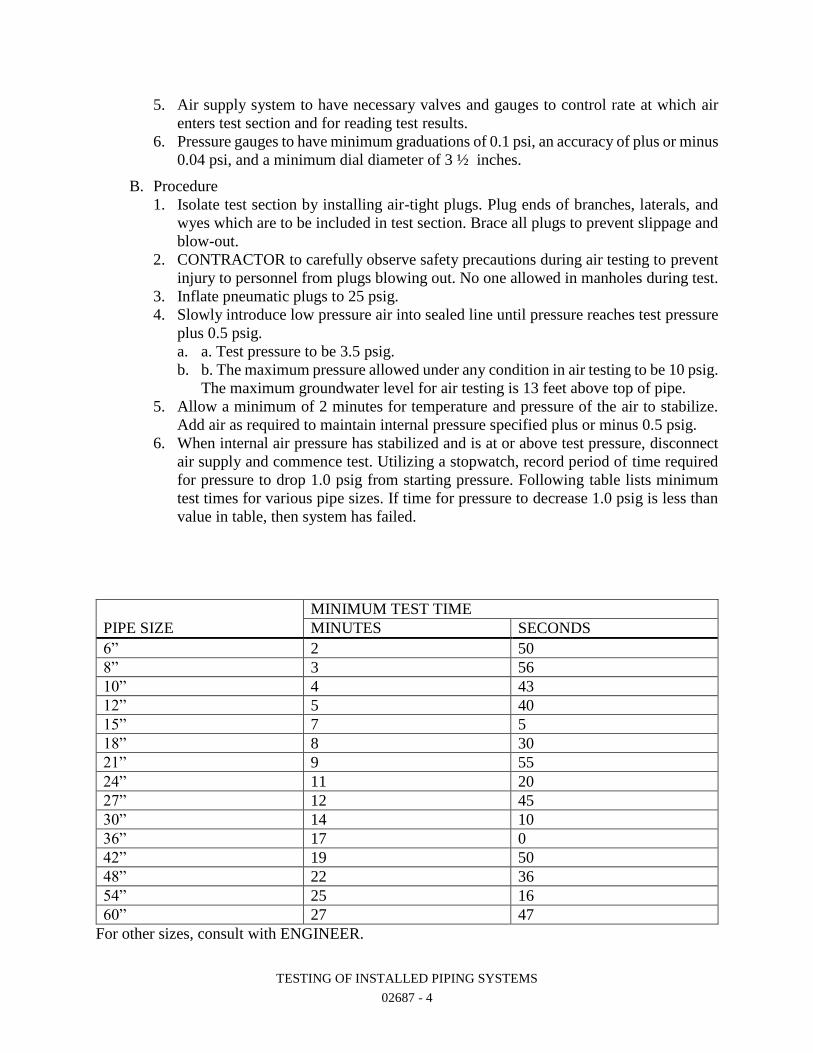
TESTING OF INSTALLED PIPING SYSTEMS
02687 - 4
5. Air supply system to have necessary valves and gauges to control rate at which air
enters test section and for reading test results.
6. Pressure gauges to have minimum graduations of 0.1 psi, an accuracy of plus or minus
0.04 psi, and a minimum dial diameter of 3 ½ inches.
B. Procedure
1. Isolate test section by installing air-tight plugs. Plug ends of branches, laterals, and
wyes which are to be included in test section. Brace all plugs to prevent slippage and
blow-out.
2. CONTRACTOR to carefully observe safety precautions during air testing to prevent
injury to personnel from plugs blowing out. No one allowed in manholes during test.
3. Inflate pneumatic plugs to 25 psig.
4. Slowly introduce low pressure air into sealed line until pressure reaches test pressure
plus 0.5 psig.
a. a. Test pressure to be 3.5 psig.
b. b. The maximum pressure allowed under any condition in air testing to be 10 psig.
The maximum groundwater level for air testing is 13 feet above top of pipe.
5. Allow a minimum of 2 minutes for temperature and pressure of the air to stabilize.
Add air as required to maintain internal pressure specified plus or minus 0.5 psig.
6. When internal air pressure has stabilized and is at or above test pressure, disconnect
air supply and commence test. Utilizing a stopwatch, record period of time required
for pressure to drop 1.0 psig from starting pressure. Following table lists minimum
test times for various pipe sizes. If time for pressure to decrease 1.0 psig is less than
value in table, then system has failed.
PIPE SIZE
MINIMUM TEST TIME
MINUTES SECONDS
6” 2 50
8” 3 56
10” 4 43
12” 5 40
15” 7 5
18” 8 30
21” 9 55
24” 11 20
27” 12 45
30” 14 10
36” 17 0
42” 19 50
48” 22 36
54” 25 16
60” 27 47
For other sizes, consult with ENGINEER.
TESTING OF INSTALLED PIPING SYSTEMS
02687 - 5
7. Test may be discontinued when prescribed minimum test time has been reached, even
though 1.0 psig pressure drop has not occurred.
8. Release air from pipe slowly and remove plugs at conclusion of test.
3.04 HIGH PRESSURE AIR TESTING
A. Purge line to be tested with water or high velocity air as appropriate to system being
tested.
B. Unless otherwise specified, perform two-hour pressure test at 150 psig using dry, oil free
air. Unless otherwise specified, no leaks will be allowed.
C. Test joints with soapy water solution for leaks.
3.05 EXFILTRATION TESTING
A. General: Take precautions required to prevent damage to lines and appurtenances being
tested. Repair any damage resulting from test at CONTRACTOR's expense. Conduct test
in presence of ENGINEER.
B. Preparation: Seal ends of section being tested with water-tight plugs. Fill section with
water 24 hours prior to start of test. Vent line during filling so that no air is trapped in
line. Leave outlets of stacks, inlets, and service lines exposed and unplugged until after
exfiltration test has been made. Outlets terminating below level of test water surface to
be temporarily extended upward by installing additional lengths of pipe or by plugging.
After completion of satisfactory test, remove lengths of pipe added for test.
C. Duration of Test: Test for at least 2 hours with minimum head of 4 feet measured above
top crown, inside pipe at upper end of section being tested.
D. Allowable Leakage: Allowable leakage or exfiltration in any individual section or entire
sewer line under construction is defined in Paragraph 3.07. Remove and replace or make
approved corrective repairs to any section or line which has leakage or exfiltration that
exceeds above amount. Repair any individual leaks that may appear whether or not
overall section meets leakage requirements. For this purpose, any steady stream will be
considered a leak, while a drip will not. Individual leaks ordinarily will be revealed by
looking through sewer with a light while groundwater level is over sewer, during backfill
operations, or immediately after water from exfiltration tests is emptied from sewer line.
Settlement in backfill during exfiltration tests will be taken and an indication of leakage.
E. Measurement of Leakage: Measure leakage or exfiltration during test period by adding
measured quantities of water to maintain water level in test structure. Quantity of water
added to maintain water level is amount of leakage or exfiltration.
F. Retest: Sewers failing to meet requirements of leakage test to be tested again for leakage
after repair by CONTRACTOR. No sewer will be accepted until leakage is less than
allowable.
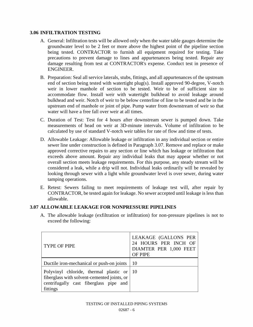
TESTING OF INSTALLED PIPING SYSTEMS
02687 - 6
3.06 INFILTRATION TESTING
A. General: Infiltration tests will be allowed only when the water table gauges determine the
groundwater level to be 2 feet or more above the highest point of the pipeline section
being tested. CONTRACTOR to furnish all equipment required for testing. Take
precautions to prevent damage to lines and appurtenances being tested. Repair any
damage resulting from test at CONTRACTOR's expense. Conduct test in presence of
ENGINEER.
B. Preparation: Seal all service laterals, stubs, fittings, and all appurtenances of the upstream
end of section being tested with watertight plug(s). Install approved 90-degree, V-notch
weir in lower manhole of section to be tested. Weir to be of sufficient size to
accommodate flow. Install weir with watertight bulkhead to avoid leakage around
bulkhead and weir. Notch of weir to be below centerline of line to be tested and be in the
upstream end of manhole or joint of pipe. Pump water from downstream of weir so that
water will have a free fall over weir at all times.
C. Duration of Test: Test for 4 hours after downstream sewer is pumped down. Take
measurements of head on weir at 3D-minute intervals. Volume of infiltration to be
calculated by use of standard V-notch weir tables for rate of flow and time of tests.
D. Allowable Leakage: Allowable leakage or infiltration in any individual section or entire
sewer line under construction is defined in Paragraph 3.07. Remove and replace or make
approved corrective repairs to any section or line which has leakage or infiltration that
exceeds above amount. Repair any individual leaks that may appear whether or not
overall section meets leakage requirements. For this purpose, any steady stream will be
considered a leak, while a drip will not. Individual leaks ordinarily will be revealed by
looking through sewer with a light while groundwater level is over sewer, during water
tamping operations.
E. Retest: Sewers failing to meet requirements of leakage test will, after repair by
CONTRACTOR, be tested again for leakage. No sewer accepted until leakage is less than
allowable.
3.07 ALLOWABLE LEAKAGE FOR NONPRESSURE PIPELINES
A. The allowable leakage (exfiltration or infiltration) for non-pressure pipelines is not to
exceed the following:
TYPE OF PIPE
LEAKAGE (GALLONS PER
24 HOURS PER INCH OF
DIAMTER PER 1,000 FEET
OF PIPE
Ductile iron-mechanical or push-on joints 10
Polyvinyl chloride, thermal plastic or
fiberglass with solvent-cemented joints, or
centrifugally cast fiberglass pipe and
fittings
10
TESTING OF INSTALLED PIPING SYSTEMS
02687 - 7
Concrete with rubber joints 20
Concrete with steel and rubber joints 10
Clay with rubber gasket joints 20
Cast iron soil pipe:
1. Drains and Vents 0
2. Sewer Laterals *
All piping inside structures 0
* The same allowable as pipe to which it is connected.
B. Regardless of the above allowable leakage, any visible leaks detected to be permanently
stopped.
3.08 PIPELINE SETTLEMENT TESTING
A. TV Inspection
1. During infiltration test or after exfiltration test, pipe to be TV inspected for possible
settlement. When air testing has been used, run water through pipe to permit
meaningful observations. Any pipe settlement which causes ponding of water in pipe
is an indication of system failure.
2. TV inspection required on all sanitary sewers greater than 30 inches in diameter and
all sewers installed with curved alignment.
B. Mandrel Testing: All plastic piping materials used for gravity sewers to be subjected to a
95% mandrel test. Mandrel testing to be completed no sooner than four weeks after
backfilling has been completed. A Go-No-Go deflection testing mandrel with a minimum
of eight runners to be used for testing. Mandrel to be furnished with proving ring.
Dimensions of the mandrel for SDR-35 PVC, to be as shown in Attachment "A" to this
Section. For other wall thicknesses, consult ENGINEER. Testing to be as follows:
1. Completely flush line and clean pipe of debris.
2. Install pull rope in section to be tested.
3. Attach pull rope and retrieval rope to mandrel.
4. Insert mandrel in pipe. Remove slack from pull rope and place tape marker on rope
at end of pipe where mandrel will exit. Tape marker to be used to determine mandrel
location in line.
5. Using guide pulleys, pull mandrel through line. Use tape marker to determine location
of over-deflected sections.
6. All pipe sections failing to pass the mandrel to be removed and reinstalled.
7. Repeat testing until system passes.
3.09 LEAKAGE TESTING FOR PRESSURE PIPELINES
A. Leakage test to be conducted concurrently with hydrostatic pressure tests.
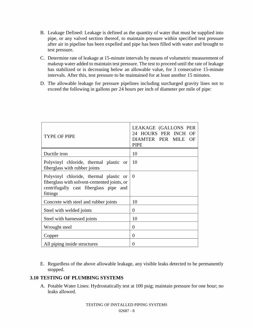
TESTING OF INSTALLED PIPING SYSTEMS
02687 - 8
B. Leakage Defined: Leakage is defined as the quantity of water that must be supplied into
pipe, or any valved section thereof, to maintain pressure within specified test pressure
after air in pipeline has been expelled and pipe has been filled with water and brought to
test pressure.
C. Determine rate of leakage at 15-minute intervals by means of volumetric measurement of
makeup water added to maintain test pressure. The test to proceed until the rate of leakage
has stabilized or is decreasing below an allowable value, for 3 consecutive 15-minute
intervals. After this, test pressure to be maintained for at least another 15 minutes.
D. The allowable leakage for pressure pipelines including surcharged gravity lines not to
exceed the following in gallons per 24 hours per inch of diameter per mile of pipe:
TYPE OF PIPE
LEAKAGE (GALLONS PER
24 HOURS PER INCH OF
DIAMTER PER MILE OF
PIPE
Ductile iron 10
Polyvinyl chloride, thermal plastic or
fiberglass with rubber joints
10
Polyvinyl chloride, thermal plastic or
fiberglass with solvent-cemented joints, or
centrifugally cast fiberglass pipe and
fittings
0
Concrete with steel and rubber joints 10
Steel with welded joints 0
Steel with harnessed joints 10
Wrought steel 0
Copper 0
All piping inside structures 0
E. Regardless of the above allowable leakage, any visible leaks detected to be permanently
stopped.
3.10 TESTING OF PLUMBING SYSTEMS
A. Potable Water Lines: Hydrostatically test at 100 psig; maintain pressure for one hour; no
leaks allowed.
TESTING OF INSTALLED PIPING SYSTEMS
02687 - 9
B. Test vertical soil and waste vents as soon as set. Plug outlets, fill to top of vertical lines,
and hold for 24 hours. Make final test after roughing in is complete and before connecting
sewer.
C. Perform smoke test on drain, waste and vent (DWV) lines in accordance with the
following:
1. Perform smoke test on DWV lines after all fixtures have been permanently connected
and all traps filled with water.
2. Close all windows and doors in the building and turn HVAC system off for the
duration of the smoke test.
3. One or more smoke machines to be connected to main building clean out or other
suitable connection. Smoke machines to produce a thick penetrating smoke. Smoke
produced by chemical mixtures are not acceptable.
4. Add smoke to the system until smoke is visible at vent stacks. Plug vent stacks and
continue to add smoke until a pressure of 1-inch water column is produced. Maintain
pressure for a minimum of 15 minutes.
5. Visually inspect each connection and fixture for smoke. Any odor or sign of smoke
is indication of system failure.
6. Repair all leaks and retest.
3.11 SPECIAL TESTING PROCEDURES
A. Chlorine Gas Piping Systems
1. Clean all portions of the chlorine gas system with a chlorinated solvent such as
trichloroethylene. Hydrocarbons or alcohols are not allowed. Cleaning may be
accomplished by pulling a cloth saturated with solvent through each length of pipe.
2. Hydrostatically test the system at 300 psig for two hours.
3. Drying: Chlorine gas lines are to be dried prior to introducing gas into the system.
Drying to be accomplished by passing steam through the line until all lines are
thoroughly heated. While steaming, allow condensate and foreign matter to drain out.
Disconnect the steam supply and drain all low spots. While the line is still warm dry
air (air with a dew point of -40°F or less) is to be blown through the line until dry. Air
drying may take several hours.
4. Gas Testing: After the system is dry, pressurize the system to 150 psig with dry air (-
40°F) or nitrogen and test for leaks at joints using soapy water. After testing all joints
hold pressure for 30 minutes.
5. Introduce chlorine gas gradually into system and test for leaks at all joints using
ammonia water solution.
B. LPG or Natural Gas Piping Systems
1. After piping installation is complete, but before installation of gas cocks, test the
piping system with LP-gas or air at a pressure of 15 psig for 30 minutes. The source
of pressure is to be disconnected from the system and there is to be no loss of pressure
on the gauge during the test period.
2. After installation of gas cocks, test the system again with air or LP-gas at 5 psig for
15 minutes. Gas source is to be disconnected and no loss of pressure allowed.
TESTING OF INSTALLED PIPING SYSTEMS
02687 - 10
3. If appliances are installed at the same time as the piping system, a final pressure test
(including appliance valves) is to be made. The system is to be tested at not more than
14" water column and not less than 10" water column for a period of 15 minutes
without a drop in pressure.
4. During testing, the piping system is to remain at a constant temperature so that a rise
in temperature with a resultant rise in pressure does not mask small leaks.
C. Air Piping Systems
1. Depending on the size of the piping, the system is to be hydrostatically tested or tested
with high pressure air. In general, all piping larger than 2" in size is to be
hydrostatically tested. Piping 2" and smaller may be hydrostatically tested or high
pressure air tested (CONTRACTOR's Option).
2. High pressure air systems (systems with a working pressure greater than 15 psig) are
to receive a 24-hour stand pressure time test. Test pressure to be 150% of system
working pressure, but not less than 150 psig. System to hold pressure for 24-hours
with a loss of no greater than 5 psig.
3. Low pressure air systems (systems with a working pressure less than 15 psig) are to
receive a 2-hour stand pressure time test at 25 psig. No pressure loss allowed.
D. Vacuum Piping: Test and purge system in accordance with NFPA 56F.
E. Oil and Fuel Lines: Purge lines and hydrostatically or high pressure air test (depending
on pipe size) at the specified pressure. No leaks will be allowed. After testing is
completed, purge lines with nitrogen or carbon dioxide before admitting product.
3.12 TESTING PROCEDURES AT INTERFACES WITH EXISTING PIPING OR
BOUNDARIES
A. New Piping That Connects to Existing Piping
1. Complete piping up to final closure between existing and new piping.
2. Test new piping per applicable paragraph of this Specification by installing a closure
piece to isolate the new section. Test pressure as specified or noted.
3. Complete connection to existing piping. If underground, leave joint exposed.
4. Test piping again, per applicable paragraph of this Specification, to verify the
integrity of the completed joint.
a. Isolate existing piping by installing test plugs or closing valves if they exist. Only
isolate piping necessary to verify joint integrity. Test pressure at the interface
between new and existing piping to be 110% of the working pressure at the
interface. Hold test pressure for one hour. If pressure test fails, maintain pressure
at the joint by adding water to the system and visually inspect joint for leaks. If
no leaks are visible at the interface, no further testing is required. If leaks are
visible, repair and retest.
b. Only when noted on PLANS or specified elsewhere, place piping in service and
visually inspect joint(s). If no leaks are visible at the interface, no further testing
is required. If leaks are visible, repair and retest.
5. Coordination with plant operations is required for removing line from service, closing
valves and shutdowns.
B. Pipe Testing at the Boundary between Two Construction Contracts
1. If Connecting Pipe Has Not Been Installed:
TESTING OF INSTALLED PIPING SYSTEMS
02687 - 11
a. Install closure piece (Le. plug, blind flange, etc.) at the boundary and test per
applicable paragraph of this Specification. Test pressure to be as specified.
2. If Pipe at Boundary Is Installed:
a. Complete piping up to final closure at the boundary.
b. Test new piping per applicable paragraph of this Specification by installing a
closure piece to isolate the new section. Test pressure as specified.
c. Complete connection at boundary. If underground, leave joint exposed.
d. Retest piping. Test pressure to be 100% of the working pressure at the boundary.
If there are no visible leaks at the interface, then no further testing is required. If
leaks are visible at the interface, repair and retest.
3. Installed piping at the boundary between two construction contracts is defined as
piping that has been installed and tested per Contract requirements and approved by
the ENGINEER.
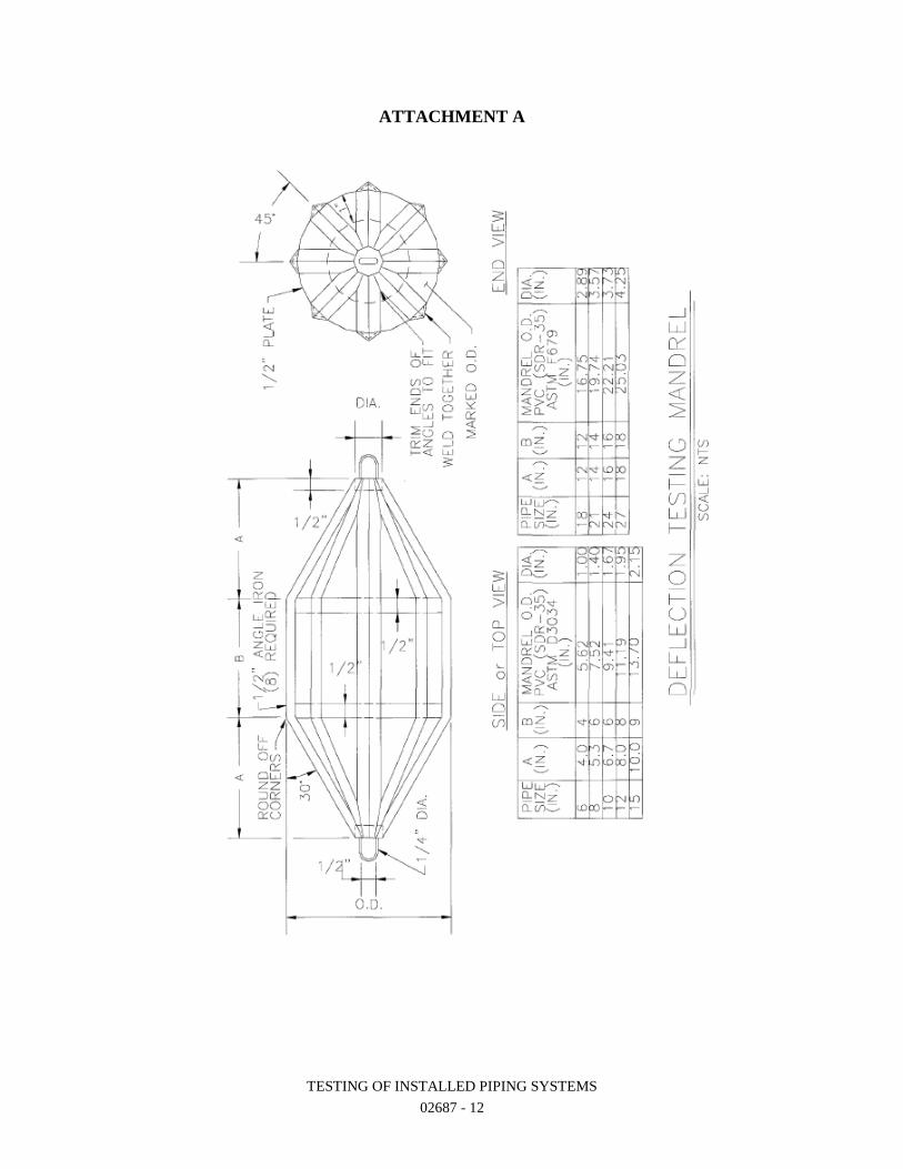
TESTING OF INSTALLED PIPING SYSTEMS
02687 - 12
ATTACHMENT A
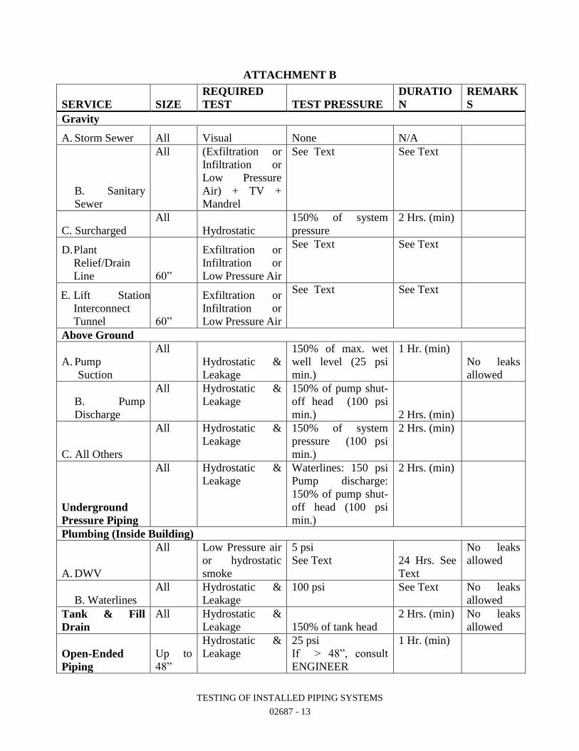
TESTING OF INSTALLED PIPING SYSTEMS
02687 - 13
ATTACHMENT B
SERVICE SIZE
REQUIRED
TEST TEST PRESSURE
DURATIO
N
REMARK
S
Gravity
A. Storm Sewer All Visual None N/A
B. B. Sanitary
Sewer
All (Exfiltration or
Infiltration or
Low Pressure
Air) + TV +
Mandrel
See Text See Text
C. Surcharged
All
Hydrostatic
150% of system
pressure
2 Hrs. (min)
D. Plant
Relief/Drain
Line 60”
Exfiltration or
Infiltration or
Low Pressure Air
See Text See Text
E. Lift Station
Interconnect
Tunnel 60”
Exfiltration or
Infiltration or
Low Pressure Air
See Text See Text
Above Ground
A. Pump
Suction
All
Hydrostatic &
Leakage
150% of max. wet
well level (25 psi
min.)
1 Hr. (min)
No leaks
allowed
B. B. Pump
Discharge
All Hydrostatic &
Leakage
150% of pump shut-
off head (100 psi
min.) 2 Hrs. (min)
C. All Others
All Hydrostatic &
Leakage
150% of system
pressure (100 psi
min.)
2 Hrs. (min)
Underground
Pressure Piping
All Hydrostatic &
Leakage
Waterlines: 150 psi
Pump discharge:
150% of pump shut-
off head (100 psi
min.)
2 Hrs. (min)
Plumbing (Inside Building)
A. DWV
All Low Pressure air
or hydrostatic
smoke
5 psi
See Text 24 Hrs. See
Text
No leaks
allowed
B. B. Waterlines
All Hydrostatic &
Leakage
100 psi See Text No leaks
allowed
Tank & Fill
Drain
All Hydrostatic &
Leakage 150% of tank head
2 Hrs. (min) No leaks
allowed
Open-Ended
Piping
Up to
48”
Hydrostatic &
Leakage
25 psi
If > 48”, consult
ENGINEER
1 Hr. (min)
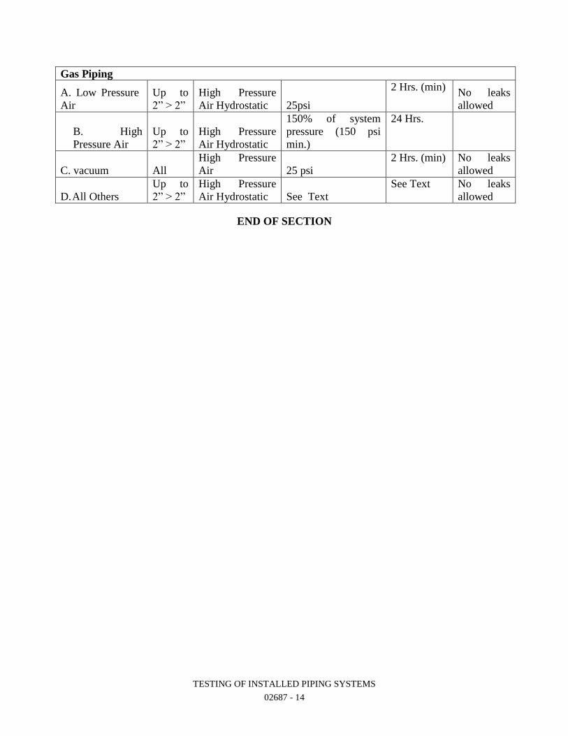
TESTING OF INSTALLED PIPING SYSTEMS
02687 - 14
Gas Piping
A. Low Pressure
Air
Up to
2” > 2”
High Pressure
Air Hydrostatic 25psi
2 Hrs. (min) No leaks
allowed
C. B. High
Pressure Air
Up to
2” > 2”
High Pressure
Air Hydrostatic
150% of system
pressure (150 psi
min.)
24 Hrs.
C. vacuum All
High Pressure
Air 25 psi
2 Hrs. (min) No leaks
allowed
D. All Others
Up to
2” > 2”
High Pressure
Air Hydrostatic See Text
See Text No leaks
allowed
END OF SECTION
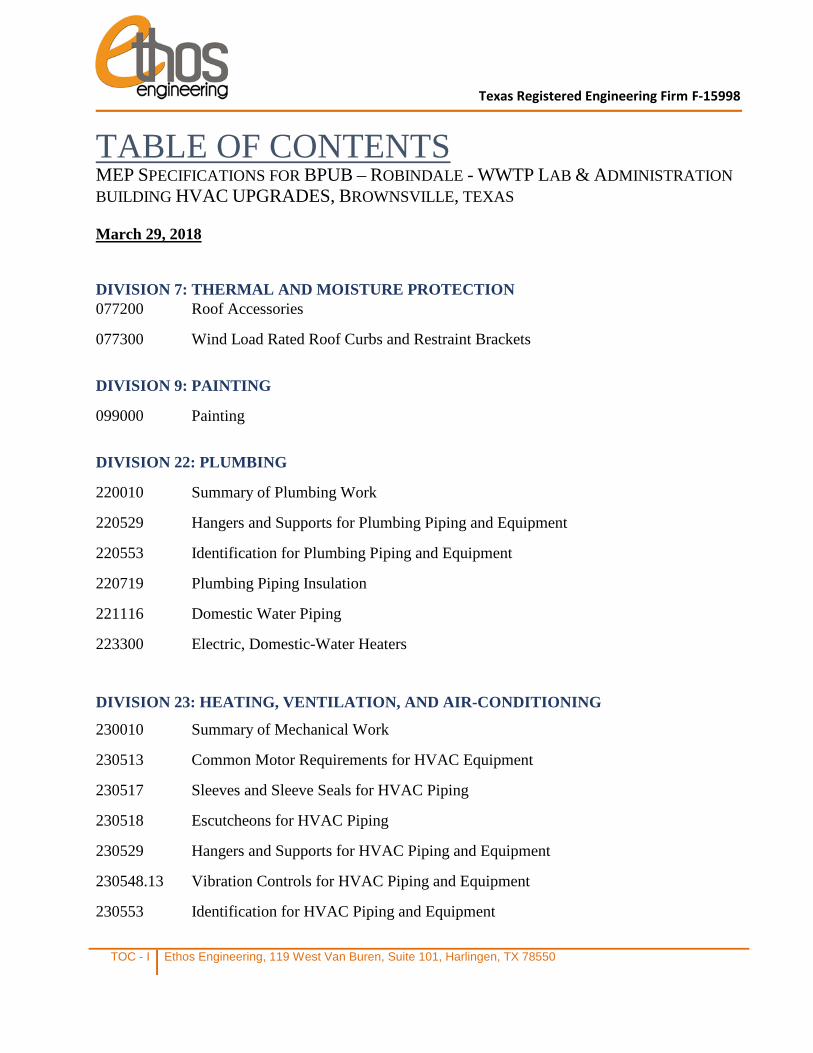
Texas Registered Engineering Firm F-15998
TOC - I Ethos Engineering, 119 West Van Buren, Suite 101, Harlingen, TX 78550
TABLE OF CONTENTS MEP SPECIFICATIONS FOR BPUB – ROBINDALE - WWTP LAB & ADMINISTRATION BUILDING HVAC UPGRADES, BROWNSVILLE, TEXAS March 29, 2018
DIVISION 7: THERMAL AND MOISTURE PROTECTION 077200 Roof Accessories
077300 Wind Load Rated Roof Curbs and Restraint Brackets
DIVISION 9: PAINTING
099000 Painting
DIVISION 22: PLUMBING
220010 Summary of Plumbing Work
220529 Hangers and Supports for Plumbing Piping and Equipment
220553 Identification for Plumbing Piping and Equipment
220719 Plumbing Piping Insulation
221116 Domestic Water Piping
223300 Electric, Domestic-Water Heaters
DIVISION 23: HEATING, VENTILATION, AND AIR-CONDITIONING
230010 Summary of Mechanical Work
230513 Common Motor Requirements for HVAC Equipment
230517 Sleeves and Sleeve Seals for HVAC Piping
230518 Escutcheons for HVAC Piping
230529 Hangers and Supports for HVAC Piping and Equipment
230548.13 Vibration Controls for HVAC Piping and Equipment
230553 Identification for HVAC Piping and Equipment
TOC - II Ethos Engineering, 119 West Van Buren, Suite 101, Harlingen, TX 78550
230593 Testing, Adjusting, and Balancing for HVAC
230713 Duct Insulation
230719 HVAC Piping Insulation
232300 Refrigerant Piping
233113 Metal Ducts
233300 Air Duct Accessories
233423 HVAC Power Ventilators
233713 Diffusers, Registers, and Grilles
238126 Split System Air Conditioning System
DIVISION 26: ELECTRICAL
260010 Summary of Electrical Work
260519 Low-Voltage Electrical Power Conductors and Cables
260529 Hangers and Supports for Electrical Systems
260533 Raceways and Boxes for Electrical Systems
260544 Sleeves and Sleeve Seals for Electrical Raceways and Cabling
260553 Identification for Electrical Systems
262816 Enclosed Switches and Circuit Breakers
DRAWINGS
MECHANICAL:
COVER COVER
ME1.1 MECHANICAL GENERAL NOTES, LEGENDS & ABBREVIATIONS
ME1.2 ELECTRICAL SPECIFICATIONS AND LEGEND
ME2.1 MECHANICAL & ELECTRICAL DEMOLITION FLOOR PLAN
ME3.1 MECHANICAL & ELECTRICAL FLOOR PLAN
ME4.1 MECHANICAL & ELECTRICAL SCHEDULES
ME5.1 MECHANICAL & ELECTRICAL DETAILS
SECTION 077200 - ROOF ACCESSORIES
Ethos Engineering 077200 - 1
PART 1 - GENERAL
1.1 RELATED DOCUMENTS
A. Drawings and general provisions of the Contract, including General and Supplementary Conditions and Division 1 Specification Sections, apply to this Section.
1.2 SUMMARY
A. This Section includes the following: New Factory fabricated roof curb. Coordinate with Drawings and Notes.
1.3 SUBMITTALS
A. Product Data: For each type of product indicated. Include construction details, materials, dimensions of individual components and profiles, and finishes.
B. Coordination Drawings: Roof plans drawn to scale and coordinating penetrations and roof-mounted items. Show the following: 1. Size and location of roof accessories specified in this Section. 2. Method of attaching roof accessories to roof or building structure. 3. Other roof-mounted items including mechanical and electrical equipment, ductwork,
piping, and conduit. 4. Coordinate dimensions with shop drawings of equipment to be supported.
1.4 QUALITY ASSURANCE
A. Substitutions: Requests for substitution shall be submitted in writing at least 10 days prior to bid date and shall be accompanied by product literature and samples. No substitution will be permitted after bid date.
B. Standards: Comply with the following: 1. SMACNA's "Architectural Sheet Metal Manual" details for fabrication of units, including
flanges and cap flashing to coordinate with type of roofing indicated. 2. NRCA's "Roofing and Waterproofing Manual" details for installing units.
PART 2 - PRODUCTS
2.1 MATERIALS, GENERAL
A. G-90 galvanized steel with paint-grip coating.
B. Insulation: Manufacturer's standard rigid or semirigid glass-fiber board of 2” thickness, 1-1/2lb density, R8 value.
SECTION 077200 - ROOF ACCESSORIES
Ethos Engineering 077200 - 2
C. Wood Nailers: Softwood lumber, pressure treated with waterborne preservatives for aboveground use, complying with AWPA C2; not less than 1-1/2 inches thick.
D. Fasteners: Stainless steel metal as recommended by manufacturer. Match finish of exposed fasteners with finish of material being fastened.
E. Gaskets: Manufacturer's standard tubular or fingered design of neoprene, EPDM, or PVC; or flat design of foam rubber, sponge neoprene, or cork.
F. Bituminous Coating: SSPC-Paint 12, solvent-type bituminous mastic, nominally free of sulfur and containing no asbestos fibers, compounded for 15-mil dry film thickness per coating.
G. Mastic Sealant: Polyisobutylene; nonhardening, nonskinning, nondrying, nonmigrating sealant.
H. Elastomeric Sealant: Generic type recommended by unit manufacturer that is compatible with joint surfaces; ASTM C 920, Type S, Grade NS, Class 25, and Uses NT, G, A, and, as applicable to joint substrates indicated, O.
I. Roofing Cement: ASTM D 4586, nonasbestos, fibrated asphalt cement designed for trowel application or other adhesive compatible with roofing system.
2.2 ROOF CURBS
A. General: Provide roof curbs capable of supporting superimposed live and dead loads, including equipment loads and other construction to be supported on roof curbs. Coordinate dimensions with rough-in information or Shop Drawings of equipment to be supported.
B. Fabrication: Unless otherwise indicated or required for strength, fabricate units from minimum 16 gauge, galvanized steel with paint grip coating, with welded corners and with seams joined by continuous water and air-tight welds. Tack or spot welding is unacceptable. 1. All external welds shall be prepared and coated with corrosion inhibitor compound. 2. Curb and curb adapter walls shall be insulated with 1-1/2” thick, three-pound density
insulation. Exposed edges shall be encapsulated to ensure no insulation erodes into the air stream. Insulation shall be either foil faced or coated with antimicrobial coating such that the fibers are not airborne over the life of the building.
3. Provide preservative-treated wood nailers at tops of curbs and formed flange at perimeter bottom for mounting to roof.
4. Provide formed cants and base profile coordinated with roof insulation thickness. 5. The Manufacturer shall limit static pressure gain to .25 inches/water gauge 6. Fabricate units to minimum height of 18 inches, unless otherwise indicated. 7. Changes in airflow direction to be accomplished by 90-degree elbows with turning vanes. 8. Curb and curb adapters shall be manufactured in one piece except when width exceeds
108”. If width exceeds 108”, the curb shall be designed with prefabricated joints for ease of installation. It will be manufactured in separate pieces with the number and length of the pieces determined by the total length of the unit. The Manufacturer shall supply drawings for assembly and installation.
9. Curb shall provide full support of the new unit and shall include 3/8” gasketing. 10. Counter flashing shall extend over the original curb a minimum of 1” and be welded and
weatherproof.
SECTION 077200 - ROOF ACCESSORIES
Ethos Engineering 077200 - 3
2.3 FINISHES, GENERAL
A. Surface preparation: Oil, grease and other deposits of surface contamination shall be removed by solvent or detergent washing. All surfaces must be clean, dry and free of any dirt, dust, grease, oil or other deleterious materials prior to coating. Care shall be taken to ensure surfaces remain clean before and during coating process.
B. Application system: 1. Coating shall provide a standard 5 year manufacturer’s limited warranty. 2. Finish metal surfaces with corrosion protection equal to one of the following:
a. Energy Guard ZRU Primer. Finish coat shall consist of EnergyGuard DCC Cabinet Casing polyurethane coating. Coatings shall be applied by a certified applicator and shall result in a finish with an ASTMB117-90 salt spray rating of 10,000 hours.
b. Prime coat of ICI Devran 201 Universal Epoxy Primer to a thickness of not less than 3.0 mils DFT (dry film thickness) nor more than 8.0 mils DFT. Minimum recoat time for Devran 201 Universal Epoxy Primer is 3.5 hours at 77 F with 80% RH. Finish coat shall consist of Devthane 379 UVA Aliphatic Urethane Gloss Enamel applied to a thickness of not less than 1.0 mils DFT nor more than 5.0 mils DFT.
PART 3 - EXECUTION
3.1 INSTALLATION
A. General: Comply with manufacturer's written instructions. Coordinate installation of roof accessories with installation of roof deck, roof insulation, flashing, roofing membranes, penetrations, equipment, and other construction involving roof accessories to ensure that each element of the Work performs properly and that combined elements are waterproof and weather tight. Anchor roof accessories securely to supporting structural substrates so they are capable of withstanding lateral and thermal stresses, and inward and outward loading pressures.
B. Separation: Separate metal from incompatible metal or corrosive substrates, including wood, by coating concealed surfaces, at locations of contact, with bituminous coating or providing other permanent separation.
C. Flange Seals: Unless otherwise indicated, set flanges of accessory units in a thick bed of roofing cement to form a seal.
D. Cap Flashing: Where required as component of accessory, install cap flashing to provide waterproof overlap with roofing or roof flashing (as counter flashing). Seal overlap with thick bead of mastic sealant.
E. Operational Units: Test-operate units with operable components. Clean and lubricate joints and hardware. Adjust for proper operation.
3.2 CLEANING AND PROTECTION
A. Clean exposed surfaces according to manufacturer's written instructions. Touch up damaged metal coatings.
END OF SECTION 077200
SECTION 077300 - WIND LOAD RATED ROOF CURBS AND RESTRAINT BRACKETS
Ethos Engineering 077300 - 1
PART 1 - GENERAL
1.1 RELATED DOCUMENTS
A. Drawings and general provisions of the Contract, including General and Supplementary Conditions and Division 1 Specification Sections, apply to this Section.
1.2 SUMMARY
A. Design, construct, furnish and install roof curbs, brackets and related items to meet governing building codes, as demonstrated by comprehensive analysis that the load resisting capabilities meet or exceed requirements.
1.3 QUALITY ASSURANCE
A. Meet requirements of the International Building Code, ASCE Std 7, TDI, and other applicable codes for the location. This specification shall be a minimum requirement for wind load design consideration, and is not intended as a substitute for legislated, more stringent, national, state or local requirements.
B. Wind-induced forces shall be determined by governing code requirements. 1. Wind-generated force shall be reduced into an equivalent statically applied force. 2. The statically applied force shall act in horizontal and vertical directions at the center of
gravity of the rooftop mounted equipment, resulting in torsion, flexure, tension and shear forces that the wind restraint brackets shall be shown to be able to resist.
C. Install products in strict accordance with applicable codes and manufacturers’ standards. Whenever a conflict occurs between the manufacturers or construction standards, the most stringent shall apply.
1.4 SUBMITTALS
A. Manufacturer’s statement showing that the curbs and wind load restraint brackets meet the applicable code requirements, signed and sealed by a licensed professional engineer (PE). Provide the following: 1. Wind restraint calculations for all connections of rooftop-mounted equipment to roof
curb, and roof curb to the structure. 2. Drawings showing curbs, wind restraint bracket dimensions, make and model compatible
with rooftop unit, including type of connection hardware required.
PART 2 - PRODUCTS
2.1 ROOF CURBS AND RESTRAINTS
A. Approved manufacturers of roof curbs and wind load restraint brackets: 1. Curbs Plus, Complete Curbs, Thybar Corporation. 2. Others shall obtain a written pre-approval one week prior to bidding.
SECTION 077300 - WIND LOAD RATED ROOF CURBS AND RESTRAINT BRACKETS
Ethos Engineering 077300 - 2
B. Products shall be made of a material (Prime G-90 galvanized steel or galvalume) compatible with roof curb and the rooftop unit base-rail material. Dissimilar metals shall not to be used. 1. Fully welded mitered corners for wind load consideration 2. Base flange attachments for securing curb to structure. 3. Factory installed wood nailer for attachment of roofing material.
PART 3 - EXECUTION
3.1 INSTALLATION
A. Install in accordance with manufacturer's written instructions.
B. Attach rooftop equipment to roof curbs with wind load restraint brackets of size, type and quantity as determined by equipment manufacturer.
C. Attach roof curb to the building structure at the curb base flanges. Base flange attachment options include anchor bolts, welded connections and mechanical fasteners.
D. Do not install wind load restraint brackets in a manner that will result in inadequate maintenance access, base-rail damage, or roof curb reduced weight carrying capacity.
E. Prior to performing installation of restraint brackets, notify Engineer of any conflicts with other trades or equipment that may result in undesirable contact due to inadequate space or other unforeseen conditions. Notify Engineer of any discrepancies between the specifications and field conditions or changes required due to specific equipment selection prior to installation.
F. Corrective work necessitated by discrepancies or conflicts after installation shall be at the contractor's expense.
3.2 INSPECTION
A. On completion of installation, inspect the completed system and report in writing any installation error or other faults in the system that could affect the wind load resistant capabilities of the roof top assembly.
B. The Contractor shall submit a report to the project designer, including the above report with consequent steps taken to properly complete the wind load restraint installation.
END OF SECTION
SECTION 099000 – PAINTING
Ethos Engineering 09900 - 1
PART 1 - GENERAL
1.1 RELATED DOCUMENTS
A. Drawings and general provisions of the Contract, including General and Supplementary Conditions and Division 1 Specification Sections, apply to this Section.
1.2 SUMMARY
A. This Section includes surface preparation and field painting of the following: 1. Piping and piping accessories and supports 2. Exposed ductwork and accessories
B. Paint exposed surfaces, except where the paint schedules indicate that a surface or material is not to be painted or is to remain natural. If the paint schedules do not specifically mention an item or a surface, paint the item or surface the same as similar adjacent materials or surfaces whether or not schedules indicate colors. If the schedules do not indicate color or finish, the Architect will select from standard colors and finishes available.
1. Painting includes field painting of exposed bare and covered pipes (including color coding), hangers, exposed steel and iron work, and primed metal surfaces of mechanical and electrical equipment.
C. Do not paint prefinished items, concealed surfaces, finished metal surfaces, operating parts, and labels.
1. Operating parts include moving parts of operating equipment and the following:
a. Valve and damper operators. b. Linkages. c. Sensing devices. d. Motor and fan shafts.
2. Labels: Do not paint over Underwriters Laboratories (UL), Factory Mutual (FM), or other code-required labels or equipment name, identification, performance rating, or nomenclature plates.
1.3 SUBMITTALS
A. Product Data: For each paint system specified. Include block fillers and primers.
1. Material List: Provide an inclusive list of required coating materials. Indicate each material and cross-reference specific coating, finish system, and application. Identify each material by manufacturer's catalog number and general classification.
B. Samples for Initial Selection: Manufacturer's color charts showing the full range of colors available for each type of finish-coat material indicated.
SECTION 099000 – PAINTING
Ethos Engineering 09900 - 2
1.4 QUALITY ASSURANCE
A. Source Limitations: Obtain primers, and undercoat materials for each coating system from the same manufacturer as the finish coats.
1.5 DELIVERY, STORAGE, AND HANDLING
A. Deliver materials to the Project Site in manufacturer's original, unopened packages and containers bearing manufacturer's name and label.
B. Store materials not in use in tightly covered containers in a well-ventilated area at a minimum ambient temperature of 45 deg F. Maintain containers used in storage in a clean condition, free of foreign materials and residue.
1.6 PROJECT CONDITIONS
A. Apply paints only when the temperature of surfaces to be painted and surrounding air temperatures are between 50 and 90 deg F.
B. Do not apply paint in rain, fog, or mist; or when the relative humidity exceeds 85 percent; or at temperatures less than 5 deg F above the dew point; or to damp or wet surfaces.
1. Painting may continue during inclement weather if surfaces and areas to be painted are enclosed and heated within temperature limits specified by manufacturer during application and drying periods.
PART 2 - PRODUCTS
2.1 MANUFACTURERS
A. Manufacturers Names: The following manufacturers are referred to in the paint schedules by use of shortened versions of their names, which are shown in parentheses: 1. Glidden Co. (The) (Glidden). 2. Sherwin-Williams Co. (S-W).
2.2 PAINT MATERIALS, GENERAL
A. Material Compatibility: Provide primers, undercoats, and finish-coat materials that are compatible with one another and the substrates indicated under conditions of service and application, as demonstrated by manufacturer based on testing and field experience.
B. Material Quality: Provide manufacturer's best-quality paint material of the various coating types specified. Paint-material containers not displaying manufacturer's product identification will not be acceptable.
C. Colors: Match colors indicated by reference to manufacturer's color designations. 1. Condenser Water: To be coordinated with Owner.
SECTION 099000 – PAINTING
Ethos Engineering 09900 - 3
PART 3 - EXECUTION
3.1 EXAMINATION
A. Examine substrates, areas, and conditions, with the Applicator present, under which painting will be performed for compliance with paint application requirements.
1. Do not begin to apply paint until unsatisfactory conditions have been corrected and surfaces receiving paint are thoroughly dry.
3.2 PREPARATION
A. General: Remove hardware and hardware accessories, plates, machined surfaces, lighting fixtures, and similar items already installed that are not to be painted. If removal is impractical or impossible because of the size or weight of the item, provide surface-applied protection before surface preparation and painting.
1. After completing painting operations in each space or area, reinstall items removed using workers skilled in the trades involved.
B. Cleaning: Before applying paint or other surface treatments, clean the substrates of substances that could impair the bond of the various coatings. Remove oil and grease before cleaning.
1. Schedule cleaning and painting so dust and other contaminants from the cleaning process will not fall on wet, newly painted surfaces.
C. Surface Preparation: Clean and prepare surfaces to be painted according to manufacturer's written instructions for each particular substrate condition and as specified.
1. Provide barrier coats over incompatible primers or remove and reprime.
2. Ferrous Metals: Clean ungalvanized ferrous-metal surfaces that have not been shop coated; remove oil, grease, dirt, loose mill scale, and other foreign substances. Use solvent or mechanical cleaning methods that comply with the Steel Structures Painting Council's (SSPC) recommendations.
a. Blast steel surfaces clean as recommended by paint system manufacturer and according to requirements of SSPC-SP 10.
b. Treat bare and sandblasted or pickled clean metal with a metal treatment wash coat before priming.
c. Touch up bare areas and shop-applied prime coats that have been damaged. Wire-brush, clean with solvents recommended by paint manufacturer, and touch up with the same primer as the shop coat.
3. Galvanized Surfaces: Clean galvanized surfaces with nonpetroleum-based solvents so surface is free of oil and surface contaminants. Remove pretreatment from galvanized sheet metal fabricated from coil stock by mechanical methods.
D. Materials Preparation: Mix and prepare paint materials according to manufacturer's written instructions.
SECTION 099000 – PAINTING
Ethos Engineering 09900 - 4
1. Maintain containers used in mixing and applying paint in a clean condition, free of foreign materials and residue.
2. Stir material before application to produce a mixture of uniform density. Stir as required during application. Do not stir surface film into material. If necessary, remove surface film and strain material before using.
3. Use only thinners approved by paint manufacturer and only within recommended limits.
3.3 APPLICATION
A. General: Apply paint according to manufacturer's written instructions. Use applicators and techniques best suited for substrate and type of material being applied.
1. Paint colors, surface treatments, and finishes are indicated in the schedules. 2. Do not paint over dirt, rust, scale, grease, moisture, scuffed surfaces, or conditions
detrimental to formation of a durable paint film. 3. Provide finish coats that are compatible with primers used. 4. Paint surfaces behind movable equipment and furniture the same as similar exposed
surfaces. Before the final installation of equipment, paint surfaces behind permanently fixed equipment or furniture with prime coat only.
5. Sand lightly between each succeeding enamel or varnish coat.
B. Scheduling Painting: Apply first coat to surfaces that have been cleaned, pretreated, or otherwise prepared for painting as soon as practicable after preparation and before subsequent surface deterioration.
1. The number of coats and the film thickness required are the same regardless of application method. Do not apply succeeding coats until the previous coat has cured as recommended by the manufacturer. If sanding is required to produce a smooth, even surface according to manufacturer's written instructions, sand between applications.
2. Omit primer on metal surfaces that have been shop primed and touchup painted. 3. If undercoats, stains, or other conditions show through final coat of paint, apply
additional coats until paint film is of uniform finish, color, and appearance. Give special attention to ensure edges, corners, crevices, welds, and exposed fasteners receive a dry film thickness equivalent to that of flat surfaces.
4. Allow sufficient time between successive coats to permit proper drying. Do not recoat surfaces until paint has dried to where it feels firm, does not deform or feel sticky under moderate thumb pressure, and where application of another coat of paint does not cause the undercoat to lift or lose adhesion.
C. Application Procedures: Apply paints and coatings by brush, roller, spray, or other applicators according to manufacturer's written instructions.
D. Minimum Coating Thickness: Apply paint materials no thinner than manufacturer's recommended spreading rate. Provide the total dry film thickness of the entire system as recommended by the manufacturer.
E. Mechanical and Electrical Work: Painting of mechanical and electrical work is limited to items exposed in equipment rooms and in occupied spaces.
F. Mechanical items to be painted include, but are not limited to, the following:
SECTION 099000 – PAINTING
Ethos Engineering 09900 - 5
1. Piping, pipe hangers, accessories and supports. 2. Exposed ductwork, plenums, accessories and supports.
G. Prime Coats: Before applying finish coats, apply a prime coat of material, as recommended by the manufacturer, to material that is required to be painted or finished and that has not been prime coated by others. Recoat primed and sealed surfaces where evidence of suction spots or unsealed areas in first coat appears, to ensure a finish coat with no burn through or other defects due to insufficient sealing.
H. Stipple Enamel Finish: Roll and redistribute paint to an even and fine texture. Leave no evidence of rolling, such as laps, irregularity in texture, skid marks, or other surface imperfections.
I. Completed Work: Match approved samples for color, texture, and coverage. Remove, refinish, or repaint work not complying with requirements.
3.4 CLEANING
A. Cleanup: At the end of each workday, remove empty cans, rags, rubbish, and other discarded paint materials from the site.
3.5 PROTECTION
A. Protect work of other trades, whether being painted or not, against damage by painting. Correct damage by cleaning, repairing or replacing, and repainting, as approved by Architect.
B. Provide "Wet Paint" signs to protect newly painted finishes. Remove temporary protective wrappings provided by others to protect their work after completing painting operations.
3.6 PAINT SCHEDULE
A. Ferrous Metal: Semi-Gloss, Alkyd-Enamel Finish: 2 finish coats over an enamel undercoat and primer. 1. Primer: Quick-drying, rust-inhibitive, alkyd-based or epoxy-metal primer, as
recommended by the manufacturer for this substrate, applied at spreading rate recommended by the manufacturer to achieve a total dry film thickness of not less than 1.5 mils. S-W: Kem Kromik Universal Metal Primer B50NZ6/B50WZ1.
2. Undercoat: As recommended by the manufacturer for this substrate, applied at spreading rate recommended by the manufacturer to achieve a total dry film thickness of not less than 1.2 mils. S-W: High-Solids Poly-Urethane Semi-Gloss B65 350 Series, with Hardner: B60V30.
3. Finish Coat: Same as undercoat. Semi-gloss, applied at spreading rate recommended by the manufacturer to achieve a total dry film thickness of not less than 1.2 mils
END OF SECTION 099000
SECTION 220010 – SUMMARY OF PLUMBING WORK
Ethos Engineering 220010 - 1
PART 1 - GENERAL
1.1 RELATED DOCUMENTS
A. Drawings and general provisions of the Contract, including General and Supplementary Conditions and other Division 22 Specification Sections, apply to this Section.
1.2 WORK COVERED BY CONTRACT DOCUMENTS
A. The following Summary of Work is intended as an aid to achieve an understanding of the various elements of work included in the project, and is not intended to be all-inclusive. Detailed descriptions of work and requirements are given in drawings and specifications.
B. Contract Documents were prepared for the Project by: Ethos Engineering,
119 West Van Buren, Suite 101 Harlingen, Texas 78550 Phone Number: (956) 230-3435
C. Scope of Work: Refer to drawings for a detailed Scope of Work.
1. Provide all materials and labor associated with fully-operational plumbing systems for the project, including but not limited to the following:
a. Plumbing piping, instantaneous tankless electric domestic water heaters, fittings, hardware and specialties.
1.3 ALLOWANCES
A. Plumbing: See Division 1 for plumbing allowances.
1.4 COORDINATION
A. All plumbing work shall be done under sub-contract to a General Contractor. Plumbing Contractor shall coordinate all work through General Contractor, who is ultimately responsible for the entire project.
B. Prior to bidding, Plumbing Contractor shall coordinate all work in Division-22 for integration with civil work, mechanical work, electrical work, irrigation work and general construction. A detailed list of inclusion and exclusions shall be provided to General Contractors at least three days prior to the end of the period set aside to request clarifications so that coordination of any missing items may be addressed and clarified by Architect/Engineer as needed.
C. All electrical work required for operation of plumbing systems shall be coordinated through the General Contractor prior to bidding to ensure that all starters, disconnects, conduit and wiring
SECTION 220010 – SUMMARY OF PLUMBING WORK
Ethos Engineering 220010 - 2
are provided as part of the project. All components needed for a full operational installation of systems shall be provided.
D. Plumbing Contractor shall coordinate and supervise installation of all controls systems, and coordinate with electrical contractors and equipment suppliers as needed. All components needed for a full operational installation of systems shall be provided.
E. Contractor shall coordinate with other divisions for power and control of plumbing systems. It is not the intent of this specification to dictate who will conduct work, only to state the requirements of conducting the work.
F. Cooperate fully with other contractors so that work under those contracts may be carried out smoothly, without interfering with or delaying work under this Contract.
G. Coordinate with Div. 1 for work sequence and optimization of construction schedule.
H. Coordinate with Div. 23 for Mechanical System.
I. Coordinate with Div. 26 electrical contractor for providing power to plumbing equipment, and for Fire Alarm Systems interface with plumbing systems.
J. Issue written notification of the following tasks and allow five (5) days for Engineer to respond and schedule an inspection as required. Failure to issue written notification may result in work having to be redone to allow for proper inspection. It is contractor’s responsibility to make sure Engineer receives notification.
1. Upon completion of underground piping installation and prior to testing or covering up. 2. Upon completion of all water piping installation and prior to insulation and/or testing. 3. Upon completion of ductwork and prior to testing and insulating. 4. Above ceiling inspections prior to ceiling tile installation. 5. When ready to request manufacturer’s start-up of each piece of equipment. 6. When ready for Substantial Completion Inspection. 7. When ready for Final Inspection.
K. General
1. The Contractor shall execute all work hereinafter specified or indicated on accompanying Drawings. Contractor shall provide all equipment necessary and usually furnished in connection with such work and systems whether or not mentioned specifically herein or on the Drawings.
2. The Contractor shall be responsible for fitting his material and apparatus into the building and shall carefully lay out his work at the site to conform to the structural conditions, to avoid all obstructions, to conform to the details of the installation and thereby to provide an integrated satisfactory operating installation.
3. The Mechanical, Electrical, Plumbing, and associated Drawings are necessarily diagrammatic by their nature, and are not intended to show every connection in detail or every pipe or conduit in its exact location. These details are subject to the requirements of standards referenced elsewhere in these specifications, and structural and architectural conditions. The Contractor shall carefully investigate structural and finish conditions and shall coordinate the separate trades in order to avoid interference between the various phases of work. Work shall be organized and laid out so that it will be concealed in furred chases and suspended ceilings, etc., in finished portions of the building, unless
SECTION 220010 – SUMMARY OF PLUMBING WORK
Ethos Engineering 220010 - 3
specifically noted to be exposed. All exposed work shall be installed parallel or perpendicular to the lines of the building unless otherwise noted.
4. When the mechanical, electrical and plumbing drawings do not give exact details as to the elevation of pipe, conduit and ducts, the Contractor shall physically arrange the systems to fit in the space available at the elevations intended with proper grades for the functioning of the system involved. Piping, exposed conduit and the duct systems are generally intended to be installed true and square to the building construction, and located as high as possible against the structure in a neat and workmanlike manner. The Drawings do not show all required offsets, control lines, pilot lines and other location details. Work shall be concealed in all finished areas.
1.5 WORK SEQUENCE
A. Locate Utilities:
1. Coordinate with power, water, sewer, telephone, communications, and other utilities as well as designated Owner's personnel to locate all utilities prior to digging in any area.
2. Obtain any approvals required from utilities to relocate utilities. 3. Cost of relocating or bypassing utilities indicated on drawings shall be included in Base
Bid.
B. Coordinate with Division 1 requirements to optimize construction schedule.
C. Provide equipment and material submittals, coordination drawings and shop drawings as required by specifications.
D. Submit detailed plumbing Schedule of Values with Submittals. Plumbing Submittals will not be accepted without a detailed Schedule of Values.
E. Sequence construction in coordination with work by other disciplines.
1.6 CONTRACTOR USE OF PREMISES
A. Use of the Site: Limit use of the premises to work in areas indicated. Confine operations to areas within contract limits indicated. Do not disturb portions of the site beyond the areas in which the Work is indicated.
1. Driveways and Entrances: Keep driveways and entrances to construction site clear and available to other Contractors, Owner, and A/E personnel at all times. Do not use these areas for parking or storage of materials. Schedule deliveries to minimize space and time requirements for storage of materials and equipment on-site.
B. Site Safety: Take every precaution to ensure the site does not present a threat to the safety of occupants and/or workers. Minimal safety requirements include, but are not limited to the following:
1. Temporary fencing around construction areas. 2. Yellow caution tape and construction barricades along open trenches during the day.
Trenches shall be covered at night and warning lights provided on construction barricades.
3. Temporary fencing around equipment while site work is in progress.
SECTION 220010 – SUMMARY OF PLUMBING WORK
Ethos Engineering 220010 - 4
1.7 SUBMITTALS
A. Manufacturer's standard dimensioned drawings, performance and product data shall be edited to delete reference to equipment, features, or information which is not applicable to the equipment being supplied for this project.
B. Provide all plumbing submittals at the same time in one or multiple bound volumes. Include originals from manufacturer or high-quality copies. Faxes and copies of faxes are not acceptable.
C. Provide sufficient copies of approved data, with the engineer's approved stamp, for inclusion in the operations and maintenance manuals.
D. Provide detailed coordination drawings showing how plumbing system components will be installed in coordination with work by others. Engineer’s drawing files will be made available to Contractor for producing coordination and as-built drawings upon request.
1.8 SCHEDULE OF VALUES -Special Requirements
A. Plumbing Contractor shall submit a Schedule of Values reflecting the total value of Plumbing Work in the Contract, and broken down into the following items as a minimum, with a line-item for Materials/Equipment and another for Labor:
1. Plumbing fixtures and equipment 2. Plumbing materials 3. Plumbing labor 4. Allowances. 5. Miscellaneous 6. Administrative and project management.
B. Schedule of Values shall be included with bound submittals. Submittals without a Schedule of Values shall not be reviewed.
1.9 EQUIPMENT MANUFACTURERS
A. Plumbing design is based on equipment and materials scheduled and specified. These are used as the basis for performance characteristics, quality, and physical dimensions/weight.
B. Equipment and materials by other APPROVED manufacturers may be provided by Contractor. In doing so, Contractor assumes responsibility for the performance, quality, and physical dimensions of the proposed units.
C. Any costs associated with modifications to the design due to submittal of equipment and/or materials other than those used as the basis of design are the Contractor’s responsibility. This includes any design time, production of drawings, and time delays.
D. Where use of equipment and/or materials other than those used as the basis of design impact other disciplines, Contractor shall assume responsibility for all costs associated with any APPROVED modifications. This may include resizing of electrical circuits, modifying openings in the structure, relocating floor drains, etc.

SECTION 220010 – SUMMARY OF PLUMBING WORK
Ethos Engineering 220010 - 5
1.10 OPERATIONS AND MAINTENANCE MANUALS & TRAINING
A. Submit Operations and Maintenance Manuals two weeks prior to Substantial Completion Inspection. Engineer will not conduct a Substantial Completion Inspection without having reviewed Operations and Maintenance Manuals.
B. Use Operations and Maintenance Manuals as a guide for conducting training of Owner’s personnel.
PART 2 - PRODUCTS (Not Used)
PART 3 - EXECUTION (Not Used)
END OF SECTION 220010
SECTION 220529 - HANGERS AND SUPPORTS FOR PLUMBING PIPING AND EQUIPMENT
Ethos Engineering 220529 - 1
PART 1 - GENERAL
1.1 RELATED DOCUMENTS
A. Drawings and general provisions of the Contract, including General and Supplementary Conditions and Division 01 Specification Sections, apply to this Section.
1.2 SUMMARY
A. Section Includes:
1. Metal pipe hangers and supports. 2. Trapeze pipe hangers. 3. Thermal-hanger shield inserts. 4. Fastener systems. 5. Pipe stands. 6. Equipment supports.
B. Related Sections:
1. Section 055000 "Metal Fabrications" for structural-steel shapes and plates for trapeze hangers for pipe and equipment supports.
2. Section 220516 "Expansion Fittings and Loops for Plumbing Piping" for pipe guides and anchors.
3. Section 220548 "Vibration and Seismic Controls for Plumbing Piping and Equipment" for vibration isolation devices.
1.3 DEFINITIONS
A. MSS: Manufacturers Standardization Society of The Valve and Fittings Industry Inc.
1.4 PERFORMANCE REQUIREMENTS
A. Delegated Design: Design trapeze pipe hangers and equipment supports, including comprehensive engineering analysis by a qualified professional engineer, using performance requirements and design criteria indicated.
B. Structural Performance: Hangers and supports for plumbing piping and equipment shall withstand the effects of gravity loads and stresses within limits and under conditions indicated according to ASCE/SEI 7.
1. Design supports for multiple pipes, including pipe stands, capable of supporting combined weight of supported systems, system contents, and test water.
2. Design equipment supports capable of supporting combined operating weight of supported equipment and connected systems and components.
SECTION 220529 - HANGERS AND SUPPORTS FOR PLUMBING PIPING AND EQUIPMENT
Ethos Engineering 220529 - 2
1.5 ACTION SUBMITTALS
A. Product Data: For each type of product indicated.
B. Shop Drawings: Signed and sealed by a qualified professional engineer. Show fabrication and installation details and include calculations for the following; include Product Data for components:
1. Trapeze pipe hangers. 2. Metal framing systems. 3. Fiberglass strut systems. 4. Pipe stands. 5. Equipment supports.
C. Delegated-Design Submittal: For trapeze hangers indicated to comply with performance requirements and design criteria, including analysis data signed and sealed by the qualified professional engineer responsible for their preparation.
1. Detail fabrication and assembly of trapeze hangers. 2. Design Calculations: Calculate requirements for designing trapeze hangers.
1.6 INFORMATIONAL SUBMITTALS
A. Welding certificates.
1.7 QUALITY ASSURANCE
A. Structural Steel Welding Qualifications: Qualify procedures and personnel according to AWS D1.1/D1.1M, "Structural Welding Code - Steel."
B. Pipe Welding Qualifications: Qualify procedures and operators according to ASME Boiler and Pressure Vessel Code.
PART 2 - PRODUCTS
2.1 METAL PIPE HANGERS AND SUPPORTS
A. Carbon-Steel Pipe Hangers and Supports:
1. Description: MSS SP-58, Types 1 through 58, factory-fabricated components. 2. Galvanized Metallic Coatings: Pregalvanized or hot dipped. 3. Nonmetallic Coatings: Plastic coating, jacket, or liner. 4. Padded Hangers: Hanger with fiberglass or other pipe insulation pad or cushion to
support bearing surface of piping. 5. Hanger Rods: Continuous-thread rod, nuts, and washer made of carbon steel.
B. Copper Pipe Hangers:
SECTION 220529 - HANGERS AND SUPPORTS FOR PLUMBING PIPING AND EQUIPMENT
Ethos Engineering 220529 - 3
1. Description: MSS SP-58, Types 1 through 58, copper-coated-steel, factory-fabricated components.
2. Hanger Rods: Continuous-thread rod, nuts, and washer made of copper-coated steel.
2.2 TRAPEZE PIPE HANGERS
A. Description: MSS SP-69, Type 59, shop- or field-fabricated pipe-support assembly made from structural carbon-steel shapes with MSS SP-58 carbon-steel hanger rods, nuts, saddles, and U-bolts.
2.3 METAL FRAMING SYSTEMS
A. MFMA Manufacturer Metal Framing Systems: 1. Manufacturers:
a. Allied Tube & Conduit. b. Cooper B-Line, Inc. c. Flex-Strut Inc. d. GS Metals Corp. e. Thomas & Betts Corporation. f. Unistrut Corporation; Tyco International, Ltd. g. Wesanco, Inc.
2. Description: Shop- or field-fabricated pipe-support assembly for supporting multiple parallel pipes.
3. Standard: MFMA-4. 4. Channels: Continuous slotted steel channel with inturned lips. 5. Channel Nuts: Formed or stamped steel nuts or other devices designed to fit into channel
slot and, when tightened, prevent slipping along channel. 6. Hanger Rods: Continuous-thread rod, nuts, and washer made of carbon steel. 7. Metallic Coating: Hot-dipped galvanized. 8. Plastic Coating: PVC.
2.4 THERMAL-HANGER SHIELD INSERTS
A. Manufacturers:
1. Carpenter & Paterson, Inc. 2. Clement Support Services. 3. ERICO International Corporation. 4. National Pipe Hanger Corporation. 5. PHS Industries, Inc. 6. Pipe Shields, Inc.; a subsidiary of Piping Technology & Products, Inc. 7. Piping Technology & Products, Inc. 8. Rilco Manufacturing Co., Inc. 9. Value Engineered Products, Inc.
SECTION 220529 - HANGERS AND SUPPORTS FOR PLUMBING PIPING AND EQUIPMENT
Ethos Engineering 220529 - 4
B. Insulation-Insert Material for Cold Piping: ASTM C 552, Type II cellular glass with 100-psig minimum compressive strength and vapor barrier.
C. Insulation-Insert Material for Hot Piping: ASTM C 552, Type II cellular glass with 100-psig minimum compressive strength.
D. For Trapeze or Clamped Systems: Insert and shield shall cover entire circumference of pipe.
E. For Clevis or Band Hangers: Insert and shield shall cover lower 180 degrees of pipe.
F. Insert Length: Extend 2 inches beyond sheet metal shield for piping operating below ambient air temperature.
2.5 FASTENER SYSTEMS
A. Powder-Actuated Fasteners: Threaded-steel stud, for use in hardened portland cement concrete with pull-out, tension, and shear capacities appropriate for supported loads and building materials where used.
B. Mechanical-Expansion Anchors: Insert-wedge-type, stainless- steel anchors, for use in hardened portland cement concrete; with pull-out, tension, and shear capacities appropriate for supported loads and building materials where used.
2.6 PIPE STANDS
A. General Requirements for Pipe Stands: Shop- or field-fabricated assemblies made of manufactured corrosion-resistant components to support roof-mounted piping.
B. Compact Pipe Stand: One-piece plastic unit with integral-rod roller, pipe clamps, or V-shaped cradle to support pipe, for roof installation without membrane penetration.
C. Low-Type, Single-Pipe Stand: One-piece plastic base unit with plastic roller, for roof installation without membrane penetration.
D. High-Type, Single-Pipe Stand:
1. Description: Assembly of base, vertical and horizontal members, and pipe support, for roof installation without membrane penetration.
2. Base: Plastic. 3. Vertical Members: Two or more cadmium-plated-steel or stainless-steel, continuous-
thread rods. 4. Horizontal Member: Cadmium-plated-steel or stainless-steel rod with plastic or stainless-
steel, roller-type pipe support.
E. High-Type, Multiple-Pipe Stand:
1. Description: Assembly of bases, vertical and horizontal members, and pipe supports, for roof installation without membrane penetration.
2. Bases: One or more; plastic. 3. Vertical Members: Two or more protective-coated-steel channels.
SECTION 220529 - HANGERS AND SUPPORTS FOR PLUMBING PIPING AND EQUIPMENT
Ethos Engineering 220529 - 5
4. Horizontal Member: Protective-coated-steel channel. 5. Pipe Supports: Galvanized-steel, clevis-type pipe hangers.
F. Curb-Mounting-Type Pipe Stands: Shop- or field-fabricated pipe supports made from structural-steel shapes, continuous-thread rods, and rollers, for mounting on permanent stationary roof curb.
2.7 PIPE POSITIONING SYSTEMS
A. Description: IAPMO PS 42, positioning system of metal brackets, clips, and straps for positioning piping in pipe spaces; for plumbing fixtures in commercial applications.
2.8 EQUIPMENT SUPPORTS
A. Description: Welded, shop- or field-fabricated equipment support made from structural carbon-steel shapes.
2.9 MISCELLANEOUS MATERIALS
A. Structural Steel: ASTM A 36/A 36M, carbon-steel plates, shapes, and bars; black and galvanized.
B. Grout: ASTM C 1107, factory-mixed and -packaged, dry, hydraulic-cement, nonshrink and nonmetallic grout; suitable for interior and exterior applications.
1. Properties: Nonstaining, noncorrosive, and nongaseous. 2. Design Mix: 5000-psi, 28-day compressive strength.
PART 3 - EXECUTION
3.1 HANGER AND SUPPORT INSTALLATION
A. Metal Pipe-Hanger Installation: Comply with MSS SP-69 and MSS SP-89. Install hangers, supports, clamps, and attachments as required to properly support piping from the building structure.
B. Metal Trapeze Pipe-Hanger Installation: Comply with MSS SP-69 and MSS SP-89. Arrange for grouping of parallel runs of horizontal piping, and support together on field-fabricated trapeze pipe hangers.
1. Pipes of Various Sizes: Support together and space trapezes for smallest pipe size or install intermediate supports for smaller diameter pipes as specified for individual pipe hangers.
2. Field fabricate from ASTM A 36/A 36M, carbon-steel shapes selected for loads being supported. Weld steel according to AWS D1.1/D1.1M.
SECTION 220529 - HANGERS AND SUPPORTS FOR PLUMBING PIPING AND EQUIPMENT
Ethos Engineering 220529 - 6
C. Metal Framing System Installation: Arrange for grouping of parallel runs of piping, and support together on field-assembled metal framing systems.
D. Thermal-Hanger Shield Installation: Install in pipe hanger or shield for insulated piping.
E. Fastener System Installation:
1. Install powder-actuated fasteners for use in lightweight concrete or concrete slabs less than 4 inches thick in concrete after concrete is placed and completely cured. Use operators that are licensed by powder-actuated tool manufacturer. Install fasteners according to powder-actuated tool manufacturer's operating manual.
2. Install mechanical-expansion anchors in concrete after concrete is placed and completely cured. Install fasteners according to manufacturer's written instructions.
F. Pipe Stand Installation:
1. Pipe Stand Types except Curb-Mounted Type: Assemble components and mount on smooth roof surface. Do not penetrate roof membrane.
2. Curb-Mounted-Type Pipe Stands: Assemble components or fabricate pipe stand and mount on permanent, stationary roof curb. See Section 077200 "Roof Accessories" for curbs.
G. Pipe Positioning-System Installation: Install support devices to make rigid supply and waste piping connections to each plumbing fixture.
H. Install hangers and supports complete with necessary attachments, inserts, bolts, rods, nuts, washers, and other accessories.
I. Equipment Support Installation: Fabricate from welded-structural-steel shapes.
J. Install hangers and supports to allow controlled thermal and seismic movement of piping systems, to permit freedom of movement between pipe anchors, and to facilitate action of expansion joints, expansion loops, expansion bends, and similar units.
K. Install building attachments within concrete slabs or attach to structural steel. Install additional attachments at concentrated loads, including valves, flanges, and strainers, NPS 2-1/2 and larger and at changes in direction of piping. Install concrete inserts before concrete is placed; fasten inserts to forms and install reinforcing bars through openings at top of inserts.
L. Load Distribution: Install hangers and supports so that piping live and dead loads and stresses from movement will not be transmitted to connected equipment.
M. Pipe Slopes: Install hangers and supports to provide indicated pipe slopes and to not exceed maximum pipe deflections allowed by ASME B31.9 for building services piping.
N. Insulated Piping:
1. Attach clamps and spacers to piping.
a. Piping Operating above Ambient Air Temperature: Clamp may project through insulation.
SECTION 220529 - HANGERS AND SUPPORTS FOR PLUMBING PIPING AND EQUIPMENT
Ethos Engineering 220529 - 7
b. Piping Operating below Ambient Air Temperature: Use thermal-hanger shield insert with clamp sized to match OD of insert.
c. Do not exceed pipe stress limits allowed by ASME B31.9 for building services piping.
2. Install MSS SP-58, Type 39, protection saddles if insulation without vapor barrier is indicated. Fill interior voids with insulation that matches adjoining insulation.
a. Option: Thermal-hanger shield inserts may be used. Include steel weight-distribution plate for pipe NPS 4 and larger if pipe is installed on rollers.
3. Install MSS SP-58, Type 40, protective shields on cold piping with vapor barrier. Shields shall span an arc of 180 degrees.
a. Option: Thermal-hanger shield inserts may be used. Include steel weight-distribution plate for pipe NPS 4 and larger if pipe is installed on rollers.
4. Shield Dimensions for Pipe: Not less than the following:
a. NPS 1/4 to NPS 3-1/2: 12 inches long and 0.048 inch thick. b. NPS 4: 12 inches long and 0.06 inch thick. c. NPS 5 and NPS 6: 18 inches long and 0.06 inch thick. d. NPS 8 to NPS 14: 24 inches long and 0.075 inch thick. e. NPS 16 to NPS 24: 24 inches long and 0.105 inch thick.
5. Pipes NPS 8 and Larger: Include wood or reinforced calcium-silicate-insulation inserts of length at least as long as protective shield.
6. Thermal-Hanger Shields: Install with insulation same thickness as piping insulation.
3.2 EQUIPMENT SUPPORTS
A. Fabricate structural-steel stands to suspend equipment from structure overhead or to support equipment above floor.
B. Grouting: Place grout under supports for equipment and make bearing surface smooth.
C. Provide lateral bracing, to prevent swaying, for equipment supports.
3.3 METAL FABRICATIONS
A. Cut, drill, and fit miscellaneous metal fabrications for trapeze pipe hangers and equipment supports.
B. Fit exposed connections together to form hairline joints. Field weld connections that cannot be shop welded because of shipping size limitations.
C. Field Welding: Comply with AWS D1.1/D1.1M procedures for shielded, metal arc welding; appearance and quality of welds; and methods used in correcting welding work; and with the following:
SECTION 220529 - HANGERS AND SUPPORTS FOR PLUMBING PIPING AND EQUIPMENT
Ethos Engineering 220529 - 8
1. Use materials and methods that minimize distortion and develop strength and corrosion resistance of base metals.
2. Obtain fusion without undercut or overlap. 3. Remove welding flux immediately. 4. Finish welds at exposed connections so no roughness shows after finishing and so
contours of welded surfaces match adjacent contours.
3.4 ADJUSTING
A. Hanger Adjustments: Adjust hangers to distribute loads equally on attachments and to achieve indicated slope of pipe.
B. Trim excess length of continuous-thread hanger and support rods to 1-1/2 inches.
3.5 PAINTING
A. Touchup: Clean field welds and abraded areas of shop paint. Paint exposed areas immediately after erecting hangers and supports. Use same materials as used for shop painting. Comply with SSPC-PA 1 requirements for touching up field-painted surfaces.
1. Apply paint by brush or spray to provide a minimum dry film thickness of 2.0 mils.
B. Touchup: Cleaning and touchup painting of field welds, bolted connections, and abraded areas of shop paint on miscellaneous metal are specified in Section 099113 "Exterior Painting." Section 099123 "Interior Painting." Section 099600 "High-Performance Coatings."
C. Galvanized Surfaces: Clean welds, bolted connections, and abraded areas and apply galvanizing-repair paint to comply with ASTM A 780.
3.6 HANGER AND SUPPORT SCHEDULE
A. Specific hanger and support requirements are in Sections specifying piping systems and equipment.
B. Comply with MSS SP-69 for pipe-hanger selections and applications that are not specified in piping system Sections.
C. Use hangers and supports with galvanized metallic coatings for piping and equipment that will not have field-applied finish.
D. Use nonmetallic coatings on attachments for electrolytic protection where attachments are in direct contact with copper tubing.
E. Use carbon-steel pipe hangers and supports metal trapeze pipe hangers and metal framing systems and attachments for general service applications.
F. Use stainless-steel pipe hangers and attachments for hostile environment applications.
G. Use copper-plated pipe hangers and copper attachments for copper piping and tubing.
SECTION 220529 - HANGERS AND SUPPORTS FOR PLUMBING PIPING AND EQUIPMENT
Ethos Engineering 220529 - 9
H. Use padded hangers for piping that is subject to scratching.
I. Use thermal-hanger shield inserts for insulated piping and tubing.
J. Horizontal-Piping Hangers and Supports: Unless otherwise indicated and except as specified in piping system Sections, install the following types:
1. Adjustable, Steel Clevis Hangers (MSS Type 1): For suspension of noninsulated or insulated, stationary pipes NPS 1/2 to NPS 30.
2. Adjustable Pipe Saddle Supports (MSS Type 38): For stanchion-type support for pipes NPS 2-1/2 to NPS 36 if vertical adjustment is required, with steel-pipe base stanchion support and cast-iron floor flange.
3. Adjustable Roller Hangers (MSS Type 43): For suspension of pipes NPS 2-1/2 to NPS 24, from single rod if horizontal movement caused by expansion and contraction might occur.
4. Complete Pipe Rolls (MSS Type 44): For support of pipes NPS 2 to NPS 42 if longitudinal movement caused by expansion and contraction might occur but vertical adjustment is not necessary.
5. Pipe Roll and Plate Units (MSS Type 45): For support of pipes NPS 2 to NPS 24 if small horizontal movement caused by expansion and contraction might occur and vertical adjustment is not necessary.
6. Adjustable Pipe Roll and Base Units (MSS Type 46): For support of pipes NPS 2 to NPS 30 if vertical and lateral adjustment during installation might be required in addition to expansion and contraction.
K. Vertical-Piping Clamps: Unless otherwise indicated and except as specified in piping system Sections, install the following types:
1. Extension Pipe or Riser Clamps (MSS Type 8): For support of pipe risers NPS 3/4 to NPS 24.
2. Carbon- or Alloy-Steel Riser Clamps (MSS Type 42): For support of pipe risers NPS 3/4 to NPS 24 if longer ends are required for riser clamps.
L. Hanger-Rod Attachments: Unless otherwise indicated and except as specified in piping system Sections, install the following types:
1. Steel Turnbuckles (MSS Type 13): For adjustment up to 6 inches for heavy loads. 2. Steel Clevises (MSS Type 14): For 120 to 450 deg F piping installations. 3. Swivel Turnbuckles (MSS Type 15): For use with MSS Type 11, split pipe rings. 4. Malleable-Iron Sockets (MSS Type 16): For attaching hanger rods to various types of
building attachments. 5. Steel Weldless Eye Nuts (MSS Type 17): For 120 to 450 deg F piping installations.
M. Building Attachments: Unless otherwise indicated and except as specified in piping system Sections, install the following types:
1. Steel or Malleable Concrete Inserts (MSS Type 18): For upper attachment to suspend pipe hangers from concrete ceiling.
2. Top-Beam C-Clamps (MSS Type 19): For use under roof installations with bar-joist construction, to attach to top flange of structural shape.
SECTION 220529 - HANGERS AND SUPPORTS FOR PLUMBING PIPING AND EQUIPMENT
Ethos Engineering 220529 - 10
3. Side-Beam or Channel Clamps (MSS Type 20): For attaching to bottom flange of beams, channels, or angles.
4. Center-Beam Clamps (MSS Type 21): For attaching to center of bottom flange of beams. 5. Welded Beam Attachments (MSS Type 22): For attaching to bottom of beams if loads are
considerable and rod sizes are large. 6. C-Clamps (MSS Type 23): For structural shapes. 7. Top-Beam Clamps (MSS Type 25): For top of beams if hanger rod is required tangent to
flange edge. 8. Side-Beam Clamps (MSS Type 27): For bottom of steel I-beams. 9. Steel-Beam Clamps with Eye Nuts (MSS Type 28): For attaching to bottom of steel I-
beams for heavy loads. 10. Linked-Steel Clamps with Eye Nuts (MSS Type 29): For attaching to bottom of steel I-
beams for heavy loads, with link extensions. 11. Malleable-Beam Clamps with Extension Pieces (MSS Type 30): For attaching to
structural steel. 12. Welded-Steel Brackets: For support of pipes from below or for suspending from above
by using clip and rod. Use one of the following for indicated loads:
a. Light (MSS Type 31): 750 lb. b. Medium (MSS Type 32): 1500 lb. c. Heavy (MSS Type 33): 3000 lb.
13. Horizontal Travelers (MSS Type 58): For supporting piping systems subject to linear horizontal movement where headroom is limited.
N. Saddles and Shields: Unless otherwise indicated and except as specified in piping system Sections, install the following types:
1. Steel-Pipe-Covering Protection Saddles (MSS Type 39): To fill interior voids with insulation that matches adjoining insulation.
2. Protection Shields (MSS Type 40): Of length recommended in writing by manufacturer to prevent crushing insulation.
3. Thermal-Hanger Shield Inserts: For supporting insulated pipe.
O. Comply with MSS SP-69 for trapeze pipe-hanger selections and applications that are not specified in piping system Sections.
P. Comply with MFMA-103 for metal framing system selections and applications that are not specified in piping system Sections.
Q. Use mechanical-expansion anchors instead of building attachments where required in concrete construction.
R. Use pipe positioning systems in pipe spaces behind plumbing fixtures to support supply and waste piping for plumbing fixtures.
END OF SECTION 220529
SECTION 220553 - IDENTIFICATION FOR PLUMBING PIPING AND EQUIPMENT
Ethos Engineering 220553 - 1
PART 1 - GENERAL
1.1 RELATED DOCUMENTS
A. Drawings and general provisions of the Contract, including General and Supplementary Conditions and Division 01 Specification Sections, apply to this Section.
1.2 SUMMARY
A. Section Includes:
1. Equipment labels. 2. Warning signs and labels. 3. Pipe labels. 4. Stencils. 5. Valve tags. 6. Warning tags.
1.3 ACTION SUBMITTALS
A. Product Data: For each type of product indicated.
B. Samples: For color, letter style, and graphic representation required for each identification material and device.
C. Equipment Label Schedule: Include a listing of all equipment to be labeled with the proposed content for each label.
D. Valve numbering scheme.
E. Valve Schedules: For each piping system to include in maintenance manuals.
1.4 COORDINATION
A. Coordinate installation of identifying devices with completion of covering and painting of surfaces where devices are to be applied.
B. Coordinate installation of identifying devices with locations of access panels and doors.
C. Install identifying devices before installing acoustical ceilings and similar concealment.
SECTION 220553 - IDENTIFICATION FOR PLUMBING PIPING AND EQUIPMENT
Ethos Engineering 220553 - 2
PART 2 - PRODUCTS
2.1 EQUIPMENT LABELS
A. Metal Labels for Equipment:
1. Material and Thickness: Brass, 0.032-inch minimum thickness, and having predrilled or stamped holes for attachment hardware.
2. Minimum Label Size: Length and width vary for required label content, but not less than 2-1/2 by 3/4 inch.
3. Minimum Letter Size: 1/4 inch for name of units if viewing distance is less than 24 inches, 1/2 inch for viewing distances up to 72 inches, and proportionately larger lettering for greater viewing distances. Include secondary lettering two-thirds to three-quarters the size of principal lettering.
4. Fasteners: Stainless-steel rivets or self-tapping screws. 5. Adhesive: Contact-type permanent adhesive, compatible with label and with substrate.
B. Plastic Labels for Equipment: 1. Material and Thickness: Multilayer, multicolor, plastic labels for mechanical engraving,
1/8 inch thick, and having predrilled holes for attachment hardware. 2. Maximum Temperature: Able to withstand temperatures up to 160 deg F. 3. Minimum Label Size: Length and width vary for required label content, but not less than
2-1/2 by 3/4 inch. 4. Minimum Letter Size: 1/4 inch for name of units if viewing distance is less than 24
inches, 1/2 inch for viewing distances up to 72 inches, and proportionately larger lettering for greater viewing distances. Include secondary lettering two-thirds to three-quarters the size of principal lettering.
5. Fasteners: Stainless-steel rivets or self-tapping screws. 6. Adhesive: Contact-type permanent adhesive, compatible with label and with substrate.
C. Label Content: Include equipment's Drawing designation or unique equipment number, Drawing numbers where equipment is indicated (plans, details, and schedules), and the Specification Section number and title where equipment is specified.
D. Equipment Label Schedule: For each item of equipment to be labeled, on 8-1/2-by-11-inch bond paper. Tabulate equipment identification number, and identify Drawing numbers where equipment is indicated (plans, details, and schedules) and the Specification Section number and title where equipment is specified. Equipment schedule shall be included in operation and maintenance data.
2.2 WARNING SIGNS AND LABELS
A. Material and Thickness: Multilayer, multicolor, plastic labels for mechanical engraving, 1/8 inch thick, and having predrilled holes for attachment hardware.
B. Maximum Temperature: Able to withstand temperatures up to 160 deg F.
C. Minimum Label Size: Length and width vary for required label content, but not less than 2-1/2 by 3/4 inch.
SECTION 220553 - IDENTIFICATION FOR PLUMBING PIPING AND EQUIPMENT
Ethos Engineering 220553 - 3
D. Minimum Letter Size: 1/4 inch for name of units if viewing distance is less than 24 inches, 1/2 inch for viewing distances up to 72 inches, and proportionately larger lettering for greater viewing distances. Include secondary lettering two-thirds to three-quarters the size of principal lettering.
E. Fasteners: Stainless-steel rivets or self-tapping screws.
F. Adhesive: Contact-type permanent adhesive, compatible with label and with substrate.
G. Label Content: Include caution and warning information plus emergency notification instructions.
2.3 PIPE LABELS
A. General Requirements for Manufactured Pipe Labels: Preprinted, color-coded, with lettering indicating service, and showing flow direction.
B. Pretensioned Pipe Labels: Precoiled, semirigid plastic formed to cover full circumference of pipe and to attach to pipe without fasteners or adhesive.
C. Self-Adhesive Pipe Labels: Printed plastic with contact-type, permanent-adhesive backing.
D. Pipe Label Contents: Include identification of piping service using same designations or abbreviations as used on Drawings; also include pipe size and an arrow indicating flow direction.
1. Flow-Direction Arrows: Integral with piping-system service lettering to accommodate both directions or as separate unit on each pipe label to indicate flow direction.
2. Lettering Size: At least 1/2 inch.
2.4 STENCILS
A. Stencils for Piping:
1. Lettering Size: Size letters according to ASME A13.1 for piping. 2. Stencil Paint: Exterior, gloss, alkyd enamel in colors complying with recommendations in
ASME A13.1 unless otherwise indicated. Paint may be in pressurized spray-can form. 3. Identification Paint: Exterior, alkyd enamel in colors according to ASME A13.1 unless
otherwise indicated. Paint may be in pressurized spray-can form.
2.5 VALVE TAGS
A. Valve Tags: Stamped or engraved with 1/4-inch letters for piping system abbreviation and 1/2-inch numbers.
1. Tag Material: Brass, 0.032-inch minimum thickness, and having predrilled or stamped holes for attachment hardware.
2. Fasteners: Brass beaded chain.
SECTION 220553 - IDENTIFICATION FOR PLUMBING PIPING AND EQUIPMENT
Ethos Engineering 220553 - 4
B. Valve Schedules: For each piping system, on 8-1/2-by-11-inch bond paper. Tabulate valve number, piping system, system abbreviation (as shown on valve tag), location of valve (room or space), normal-operating position (open, closed, or modulating), and variations for identification. Mark valves for emergency shutoff and similar special uses.
1. Valve-tag schedule shall be included in operation and maintenance data.
2.6 WARNING TAGS
A. Description: Preprinted or partially preprinted accident-prevention tags of plasticized card stock with matte finish suitable for writing.
1. Size: 3 by 5-1/4 inches minimum. 2. Fasteners: Brass grommet and wire. 3. Nomenclature: Large-size primary caption such as "DANGER," "CAUTION," or "DO
NOT OPERATE." 4. Color: Safety yellow background with black lettering.
PART 3 - EXECUTION
3.1 PREPARATION
A. Clean piping and equipment surfaces of substances that could impair bond of identification devices, including dirt, oil, grease, release agents, and incompatible primers, paints, and encapsulants.
3.2 GENERAL INSTALLATION REQUIREMENTS
A. Coordinate installation of identifying devices with completion of covering and painting of surfaces where devices are to be applied.
B. Coordinate installation of identifying devices with locations of access panels and doors.
C. Install identifying devices before installing acoustical ceilings and similar concealment.
3.3 EQUIPMENT LABEL INSTALLATION
A. Install or permanently fasten labels on each major item of mechanical equipment.
B. Locate equipment labels where accessible and visible.
3.4 PIPE LABEL INSTALLATION
A. Piping Color Coding: Painting of piping is specified in Section 099123 "Interior Painting." and Section 099600 "High-Performance Coatings."
SECTION 220553 - IDENTIFICATION FOR PLUMBING PIPING AND EQUIPMENT
Ethos Engineering 220553 - 5
B. Stenciled Pipe Label Option: Stenciled labels may be provided instead of manufactured pipe labels, at Installer's option. Install stenciled pipe labels, complying with ASME A13.1, with painted, color-coded bands or rectangles on each piping system.
1. Identification Paint: Use for contrasting background. 2. Stencil Paint: Use for pipe marking.
C. Pipe Label Locations: Locate pipe labels where piping is exposed or above accessible ceilings in finished spaces; machine rooms; accessible maintenance spaces such as shafts, tunnels, and plenums; and exterior exposed locations as follows:
1. Near each valve and control device. 2. Near each branch connection, excluding short takeoffs for fixtures and terminal units.
Where flow pattern is not obvious, mark each pipe at branch. 3. Near penetrations through walls, floors, ceilings, and inaccessible enclosures. 4. At access doors, manholes, and similar access points that permit view of concealed
piping. 5. Near major equipment items and other points of origination and termination. 6. Spaced at maximum intervals of 50 feet along each run. Reduce intervals to 25 feet in
areas of congested piping and equipment. 7. On piping above removable acoustical ceilings. Omit intermediately spaced labels.
D. Directional Flow Arrows: Arrows shall be used to indicate direction of flow in pipes, including pipes where flow is allowed in both directions.
3.5 VALVE-TAG INSTALLATION
A. Install tags on valves and control devices in piping systems, except check valves, valves within factory-fabricated equipment units, shutoff valves, faucets, convenience and lawn-watering hose connections, and similar roughing-in connections of end-use fixtures and units. List tagged valves in a valve schedule.
B. Valve-Tag Application Schedule: Tag valves according to size, shape, and color scheme and with captions similar to those indicated in the following subparagraphs:
1. Valve-Tag Size and Shape:
a. Cold Water: 1-1/2 inches, round. b. Hot Water: 1-1/2 inches, round.
3.6 WARNING-TAG INSTALLATION
A. Write required message on, and attach warning tags to, equipment and other items where required.
END OF SECTION 220553
SECTION 220719 - PLUMBING PIPING INSULATION
Ethos Engineering 220719 - 1
PART 1 - GENERAL
1.1 RELATED DOCUMENTS
A. Drawings and general provisions of the Contract, including General and Supplementary Conditions and Division 01 Specification Sections, apply to this Section.
1.2 SUMMARY
A. Section includes insulating the following plumbing piping services: 1. Domestic cold-water piping. 2. Domestic hot-water piping. 3. Domestic recirculating hot-water piping. 4. Domestic chilled-water piping for drinking fountains. 5. Supplies and drains for handicap-accessible lavatories and sinks.
1.3 ACTION SUBMITTALS
A. Product Data: For each type of product indicated. Include thermal conductivity, water-vapor permeance thickness, and jackets (both factory- and field-applied, if any).
B. Shop Drawings: Include plans, elevations, sections, details, and attachments to other work. 1. Detail application of protective shields, saddles, and inserts at hangers for each type of
insulation and hanger. 2. Detail attachment and covering of heat tracing inside insulation. 3. Detail insulation application at pipe expansion joints for each type of insulation. 4. Detail insulation application at elbows, fittings, flanges, valves, and specialties for each
type of insulation. 5. Detail removable insulation at piping specialties, equipment connections, and access
panels. 6. Detail application of field-applied jackets. 7. Detail application at linkages of control devices.
1.4 INFORMATIONAL SUBMITTALS
A. Qualification Data: For qualified Installer.
B. Material Test Reports: From a qualified testing agency acceptable to authorities having jurisdiction indicating, interpreting, and certifying test results for compliance of insulation materials, sealers, attachments, cements, and jackets, with requirements indicated. Include dates of tests and test methods employed.
C. Field quality-control reports.
SECTION 220719 - PLUMBING PIPING INSULATION
Ethos Engineering 220719 - 2
1.5 QUALITY ASSURANCE
A. Installer Qualifications: Skilled mechanics who have successfully completed an apprenticeship program or another craft training program certified by the Department of Labor, Bureau of Apprenticeship and Training.
B. Surface-Burning Characteristics: For insulation and related materials, as determined by testing identical products according to ASTM E 84 by a testing agency acceptable to authorities having jurisdiction. Factory label insulation and jacket materials and adhesive, mastic, tapes, and cement material containers, with appropriate markings of applicable testing agency. 1. Insulation Installed Indoors: Flame-spread index of 25 or less, and smoke-developed
index of 50 or less. 2. Insulation Installed Outdoors: Flame-spread index of 75 or less, and smoke-developed
index of 150 or less.
C. Comply with the following applicable standards and other requirements specified for miscellaneous components:
1. Supply and Drain Protective Shielding Guards: ICC A117.1.
1.6 DELIVERY, STORAGE, AND HANDLING
A. Packaging: Insulation material containers shall be marked by manufacturer with appropriate ASTM standard designation, type and grade, and maximum use temperature.
1.7 COORDINATION
A. Coordinate sizes and locations of supports, hangers, and insulation shields specified in Section 220529 "Hangers and Supports for Plumbing Piping and Equipment."
B. Coordinate clearance requirements with piping Installer for piping insulation application. Before preparing piping Shop Drawings, establish and maintain clearance requirements for installation of insulation and field-applied jackets and finishes and for space required for maintenance.
C. Coordinate installation and testing of heat tracing.
1.8 SCHEDULING
A. Schedule insulation application after pressure testing systems and, where required, after installing and testing heat tracing. Insulation application may begin on segments that have satisfactory test results.
B. Complete installation and concealment of plastic materials as rapidly as possible in each area of construction.
SECTION 220719 - PLUMBING PIPING INSULATION
Ethos Engineering 220719 - 3
PART 2 - PRODUCTS
2.1 INSULATION MATERIALS
A. Comply with requirements in "Piping Insulation Schedule, General," "Indoor Piping Insulation Schedule," "Outdoor, Aboveground Piping Insulation Schedule," and "Outdoor, Underground Piping Insulation Schedule" articles for where insulating materials shall be applied.
B. Products shall not contain asbestos, lead, mercury, or mercury compounds.
C. Products that come in contact with stainless steel shall have a leachable chloride content of less than 50 ppm when tested according to ASTM C 871.
D. Insulation materials for use on austenitic stainless steel shall be qualified as acceptable according to ASTM C 795.
E. Foam insulation materials shall not use CFC or HCFC blowing agents in the manufacturing process.
F. Flexible Elastomeric Insulation: Closed-cell, sponge- or expanded-rubber materials. Comply with ASTM C 534, Type I for tubular materials. 1. Products:
a. Armaflex b. K-Flex
G. Mineral-Fiber, Preformed Pipe Insulation: 1. Products:
a. Johns Manville; Micro-Lok. b. Knauf Insulation; 1000(Pipe Insulation. c. Owens Corning; Fiberglas Pipe Insulation.
2. Type I, 850 Deg F Materials: Mineral or glass fibers bonded with a thermosetting resin. Comply with ASTM C 547, Type I, Grade A, with factory-applied ASJ. Factory-applied jacket requirements are specified in "Factory-Applied Jackets" Article.
2.2 INSULATING CEMENTS
A. Mineral-Fiber Insulating Cement: Comply with ASTM C 195. 1. Products:
a. Insulco, Division of MFS, Inc.; Triple I. b. P. K. Insulation Mfg. Co., Inc.; Super-Stik.
2.3 ADHESIVES
A. Materials shall be compatible with insulation materials, jackets, and substrates and for bonding insulation to itself and to surfaces to be insulated, unless otherwise indicated.
B. Flexible Elastomeric and Polyolefin Adhesive: Comply with MIL-A-24179A, Type II, Class I.
SECTION 220719 - PLUMBING PIPING INSULATION
Ethos Engineering 220719 - 4
1. Products: a. Foster Products Corporation, H. B. Fuller Company b. Aeroflex c. Armacell d. K-Flex
2. For indoor applications, adhesive shall have a VOC content of 50 g/L or less when calculated according to 40 CFR 59, Subpart D (EPA Method 24).
3. Adhesive shall comply with the testing and product requirements of the California Department of Health Services' "Standard Practice for the Testing of Volatile Organic Emissions from Various Sources Using Small-Scale Environmental Chambers."
C. Mineral-Fiber Adhesive: Comply with MIL-A-3316C, Class 2, Grade A.
1. Products: a. Childers Products, Division of ITW; CP-82. b. Foster Products Corporation, H. B. Fuller Company; 85-20. c. ITW TACC, Division of Illinois Tool Works; S-90/80. d. Marathon Industries, Inc.; 225. e. Mon-Eco Industries, Inc.; 22-25.
2. For indoor applications, adhesive shall have a VOC content of 80 g/L or less when calculated according to 40 CFR 59, Subpart D (EPA Method 24).
3. Adhesive shall comply with the testing and product requirements of the California Department of Health Services' "Standard Practice for the Testing of Volatile Organic Emissions from Various Sources Using Small-Scale Environmental Chambers."
D. ASJ Adhesive, and FSK Jacket Adhesive: Comply with MIL-A-3316C, Class 2, Grade A for bonding insulation jacket lap seams and joints.
1. Products: a. Childers Products, Division of ITW; CP-82. b. Foster Products Corporation, H. B. Fuller Company; 85-20. c. ITW TACC, Division of Illinois Tool Works; S-90/80. d. Marathon Industries, Inc.; 225. e. Mon-Eco Industries, Inc.; 22-25.
2. For indoor applications, adhesive shall have a VOC content of 50 g/L or less when calculated according to 40 CFR 59, Subpart D (EPA Method 24).
3. Adhesive shall comply with the testing and product requirements of the California Department of Health Services' "Standard Practice for the Testing of Volatile Organic Emissions from Various Sources Using Small-Scale Environmental Chambers."
2.4 MASTICS
A. Materials shall be compatible with insulation materials, jackets, and substrates; comply with MIL-PRF-19565C, Type II. 1. For indoor applications, use mastics that have a VOC content of 50 g/L or less when
calculated according to 40 CFR 59, Subpart D (EPA Method 24).
SECTION 220719 - PLUMBING PIPING INSULATION
Ethos Engineering 220719 - 5
B. Vapor-Barrier Mastic: Water based; suitable for indoor use on below-ambient services.
1. Products: a. Childers Products, Division of ITW; CP-35. b. Foster Products Corporation, H. B. Fuller Company; 30-90. c. ITW TACC, Division of Illinois Tool Works; CB-50. d. Marathon Industries, Inc.; 590. e. Mon-Eco Industries, Inc.; 55-40. f. Vimasco Corporation; 749.
2. Water-Vapor Permeance: ASTM E 96/E 96M, Procedure B, 0.013 perm at 43-mil dry film thickness.
3. Service Temperature Range: Minus 20 to plus 180 deg F. 4. Solids Content: ASTM D 1644, 58 percent by volume and 70 percent by weight. 5. Color: White.
2.5 SEALANTS
A. Joint Sealants: 1. Materials shall be compatible with insulation materials, jackets, and substrates. 2. Permanently flexible, elastomeric sealant. 3. Service Temperature Range: Minus 100 to plus 300 deg F. 4. Color: White or gray. 5. For indoor applications, sealants shall have a VOC content of 420 g/L or less when
calculated according to 40 CFR 59, Subpart D (EPA Method 24). 6. Sealants shall comply with the testing and product requirements of the California
Department of Health Services' "Standard Practice for the Testing of Volatile Organic Emissions from Various Sources Using Small-Scale Environmental Chambers."
B. FSK and Metal Jacket Flashing Sealants: 1. Products:
a. Childers Products, Division of ITW; CP-76-8. b. Foster Products Corporation, H. B. Fuller Company; 95-44. c. Marathon Industries, Inc.; 405. d. Mon-Eco Industries, Inc.; 44-05. e. Vimasco Corporation; 750.
2. Materials shall be compatible with insulation materials, jackets, and substrates. 3. Fire- and water-resistant, flexible, elastomeric sealant. 4. Service Temperature Range: Minus 40 to plus 250 deg F. 5. Color: Aluminum. 6. For indoor applications, sealants shall have a VOC content of 420 g/L or less when
calculated according to 40 CFR 59, Subpart D (EPA Method 24). 7. Sealants shall comply with the testing and product requirements of the California
Department of Health Services' "Standard Practice for the Testing of Volatile Organic Emissions from Various Sources Using Small-Scale Environmental Chambers."
C. ASJ Flashing Sealants, and Vinyl, PVDC, and PVC Jacket Flashing Sealants: 1. Products:
a. Childers Products, Division of ITW; CP-76. 2. Materials shall be compatible with insulation materials, jackets, and substrates. 3. Fire- and water-resistant, flexible, elastomeric sealant.
SECTION 220719 - PLUMBING PIPING INSULATION
Ethos Engineering 220719 - 6
4. Service Temperature Range: Minus 40 to plus 250 deg F. 5. Color: White. 6. For indoor applications, sealants shall have a VOC content of 420 g/L or less when
calculated according to 40 CFR 59, Subpart D (EPA Method 24). 7. Sealants shall comply with the testing and product requirements of the California
Department of Health Services' "Standard Practice for the Testing of Volatile Organic Emissions from Various Sources Using Small-Scale Environmental Chambers."
2.6 FACTORY-APPLIED JACKETS
A. Insulation system schedules indicate factory-applied jackets on various applications. When factory-applied jackets are indicated, comply with the following: 1. ASJ: White, kraft-paper, fiberglass-reinforced scrim with aluminum-foil backing;
complying with ASTM C 1136, Type I.
2.7 FIELD-APPLIED FABRIC-REINFORCING MESH
A. Woven Glass-Fiber Fabric: Approximately 2 oz./sq. yd. with a thread count of 10 strands by 10 strands/sq. in. for covering pipe and pipe fittings.
2.8 FIELD-APPLIED CLOTHS
A. Woven Glass-Fiber Fabric: Comply with MIL-C-20079H, Type I, plain weave, and presized a minimum of 8 oz./sq. yd..
2.9 FIELD-APPLIED JACKETS
A. Field-applied jackets shall comply with ASTM C 921, Type I, unless otherwise indicated.
B. Metal Jacket: 1. Products:
a. Childers Products, Division of ITW; Metal Jacketing Systems. b. PABCO Metals Corporation; Surefit. c. RPR Products, Inc.; Insul-Mate.
2. Aluminum Jacket: Comply with ASTM B 209, Alloy 3003, 3005, 3105, or 5005, Temper H-14. a. Sheet and roll stock ready for shop or field sizing. b. Finish and thickness are indicated in field-applied jacket schedules. c. Moisture Barrier for Indoor Applications: 3-mil-thick, heat-bonded polyethylene
and kraft paper d. Moisture Barrier for Outdoor Applications: 3-mil-thick, heat-bonded polyethylene
and kraft paper. e. Factory-Fabricated Fitting Covers:
1) Same material, finish, and thickness as jacket. 2) Preformed 2-piece or gore, 45- and 90-degree, short- and long-radius
elbows.
SECTION 220719 - PLUMBING PIPING INSULATION
Ethos Engineering 220719 - 7
3) Tee covers. 4) Flange and union covers. 5) End caps. 6) Beveled collars. 7) Valve covers. 8) Field fabricate fitting covers only if factory-fabricated fitting covers are not
available.
C. Underground Direct-Buried Jacket: 125-mil-thick vapor barrier and waterproofing membrane consisting of a rubberized bituminous resin reinforced with a woven-glass fiber or polyester scrim and laminated aluminum foil.
2.10 TAPES
A. ASJ Tape: White vapor-retarder tape matching factory-applied jacket with acrylic adhesive, complying with ASTM C 1136. 1. Products:
a. Avery Dennison Corporation, Specialty Tapes Division; Fasson 0835. b. Compac Corp.; 104 and 105. c. Ideal Tape Co., Inc., an American Biltrite Company; 428 AWF ASJ. d. Venture Tape; 1540 CW Plus, 1542 CW Plus, and 1542 CW Plus/SQ.
2. Width: 3 inches. 3. Thickness: 11.5 mils. 4. Adhesion: 90 ounces force/inch in width. 5. Elongation: 2 percent. 6. Tensile Strength: 40 lbf/inch in width. 7. ASJ Tape Disks and Squares: Precut disks or squares of ASJ tape.
B. FSK Tape: Foil-face, vapor-retarder tape matching factory-applied jacket with acrylic adhesive; complying with ASTM C 1136. 1. Products:
a. Avery Dennison Corporation, Specialty Tapes Division; Fasson 0827. b. Compac Corp.; 110 and 111. c. Ideal Tape Co., Inc., an American Biltrite Company; 491 AWF FSK. d. Venture Tape; 1525 CW, 1528 CW, and 1528 CW/SQ.
2. Width: 3 inches. 3. Thickness: 6.5 mils. 4. Adhesion: 90 ounces force/inch in width. 5. Elongation: 2 percent. 6. Tensile Strength: 40 lbf/inch in width. 7. FSK Tape Disks and Squares: Precut disks or squares of FSK tape.
2.11 SECUREMENTS
A. Bands: 1. Products:
a. Childers Products; Bands. b. PABCO Metals Corporation; Bands. c. RPR Products, Inc.; Bands.
SECTION 220719 - PLUMBING PIPING INSULATION
Ethos Engineering 220719 - 8
2. Stainless Steel: ASTM A 167 or ASTM A 240/A 240M, Type 316; 0.015 inch thick, 3/4 inch wide.
B. Staples: Outward-clinching insulation staples, nominal 3/4-inch-wide, stainless steel or Monel.
C. Wire: 0.080-inch nickel-copper alloy. 1. Manufacturers:
a. C & F Wire. b. Childers Products. c. PABCO Metals Corporation. d. RPR Products, Inc.
2.12 PROTECTIVE SHIELDING GUARDS
A. Protective Shielding Pipe Covers: 1. Description: Manufactured plastic wraps for covering plumbing fixture hot- and cold-
water supplies and trap and drain piping. Comply with Americans with Disabilities Act (ADA) requirements.
B. Protective Shielding Piping Enclosures: 1. Description: Manufactured plastic enclosure for covering plumbing fixture hot- and cold-
water supplies and trap and drain piping. Comply with ADA requirements.
PART 3 - EXECUTION
3.1 EXAMINATION
A. Examine substrates and conditions for compliance with requirements for installation tolerances and other conditions affecting performance of insulation application. 1. Verify that systems to be insulated have been tested and are free of defects. 2. Verify that surfaces to be insulated are clean and dry.
B. Proceed with installation only after unsatisfactory conditions have been corrected.
3.2 PREPARATION
A. Surface Preparation: Clean and prepare surfaces to be insulated. Before insulating, apply a corrosion coating to insulated surfaces as follows: 1. Carbon Steel: Coat carbon steel operating at a service temperature between 32 and 300
deg F with an epoxy coating. Consult coating manufacturer for appropriate coating materials and application methods for operating temperature range.
B. Coordinate insulation installation with the trade installing heat tracing. Comply with requirements for heat tracing that apply to insulation.
C. Mix insulating cements with clean potable water; if insulating cements are to be in contact with stainless-steel surfaces, use demineralized water.
SECTION 220719 - PLUMBING PIPING INSULATION
Ethos Engineering 220719 - 9
3.3 GENERAL INSTALLATION REQUIREMENTS
A. Install insulation materials, accessories, and finishes with smooth, straight, and even surfaces; free of voids throughout the length of piping including fittings, valves, and specialties.
B. Install insulation materials, forms, vapor barriers or retarders, jackets, and thicknesses required for each item of pipe system as specified in insulation system schedules.
C. Install accessories compatible with insulation materials and suitable for the service. Install accessories that do not corrode, soften, or otherwise attack insulation or jacket in either wet or dry state.
D. Install insulation with longitudinal seams at top and bottom of horizontal runs.
E. Install multiple layers of insulation with longitudinal and end seams staggered.
F. Do not weld brackets, clips, or other attachment devices to piping, fittings, and specialties.
G. Keep insulation materials dry during application and finishing.
H. Install insulation with tight longitudinal seams and end joints. Bond seams and joints with adhesive recommended by insulation material manufacturer.
I. Install insulation with least number of joints practical.
J. Where vapor barrier is indicated, seal joints, seams, and penetrations in insulation at hangers, supports, anchors, and other projections with vapor-barrier mastic. 1. Install insulation continuously through hangers and around anchor attachments. 2. For insulation application where vapor barriers are indicated, extend insulation on anchor
legs from point of attachment to supported item to point of attachment to structure. Taper and seal ends at attachment to structure with vapor-barrier mastic.
3. Install insert materials and install insulation to tightly join the insert. Seal insulation to insulation inserts with adhesive or sealing compound recommended by insulation material manufacturer.
4. Cover inserts with jacket material matching adjacent pipe insulation. Install shields over jacket, arranged to protect jacket from tear or puncture by hanger, support, and shield.
K. Apply adhesives, mastics, and sealants at manufacturer's recommended coverage rate and wet and dry film thicknesses.
L. Install insulation with factory-applied jackets as follows: 1. Draw jacket tight and smooth. 2. Cover circumferential joints with 3-inch-wide strips, of same material as insulation
jacket. Secure strips with adhesive and outward clinching staples along both edges of strip, spaced 4 inches o.c.
3. Overlap jacket longitudinal seams at least 1-1/2 inches. Install insulation with longitudinal seams at bottom of pipe. Clean and dry surface to receive self-sealing lap. Staple laps with outward clinching staples along edge at 4 inches o.c. a. For below-ambient services, apply vapor-barrier mastic over staples.
SECTION 220719 - PLUMBING PIPING INSULATION
Ethos Engineering 220719 - 10
4. Cover joints and seams with tape, according to insulation material manufacturer's written instructions, to maintain vapor seal.
5. Where vapor barriers are indicated, apply vapor-barrier mastic on seams and joints and at ends adjacent to pipe flanges and fittings.
M. Cut insulation in a manner to avoid compressing insulation more than 75 percent of its nominal thickness.
N. Finish installation with systems at operating conditions. Repair joint separations and cracking due to thermal movement.
O. Repair damaged insulation facings by applying same facing material over damaged areas. Extend patches at least 4 inches beyond damaged areas. Adhere, staple, and seal patches similar to butt joints.
P. For above-ambient services, do not install insulation to the following: 1. Vibration-control devices. 2. Testing agency labels and stamps. 3. Nameplates and data plates. 4. Cleanouts.
3.4 PENETRATIONS
A. Insulation Installation at Roof Penetrations: Install insulation continuously through roof penetrations. 1. Seal penetrations with flashing sealant. 2. For applications requiring only indoor insulation, terminate insulation above roof surface
and seal with joint sealant. For applications requiring indoor and outdoor insulation, install insulation for outdoor applications tightly joined to indoor insulation ends. Seal joint with joint sealant.
3. Extend jacket of outdoor insulation outside roof flashing at least 2 inches below top of roof flashing.
4. Seal jacket to roof flashing with flashing sealant.
B. Insulation Installation at Underground Exterior Wall Penetrations: Terminate insulation flush with sleeve seal. Seal terminations with flashing sealant.
C. Insulation Installation at Aboveground Exterior Wall Penetrations: Install insulation continuously through wall penetrations. 1. Seal penetrations with flashing sealant. 2. For applications requiring only indoor insulation, terminate insulation inside wall surface
and seal with joint sealant. For applications requiring indoor and outdoor insulation, install insulation for outdoor applications tightly joined to indoor insulation ends. Seal joint with joint sealant.
3. Extend jacket of outdoor insulation outside wall flashing and overlap wall flashing at least 2 inches.
4. Seal jacket to wall flashing with flashing sealant.
D. Insulation Installation at Interior Wall and Partition Penetrations (That Are Not Fire Rated): Install insulation continuously through walls and partitions.
SECTION 220719 - PLUMBING PIPING INSULATION
Ethos Engineering 220719 - 11
E. Insulation Installation at Fire-Rated Wall and Partition Penetrations: Install insulation continuously through penetrations of fire-rated walls and partitions. 1. Comply with requirements in Section 078413 "Penetration Firestopping" for firestopping
and fire-resistive joint sealers.
F. Insulation Installation at Floor Penetrations: 1. Pipe: Install insulation continuously through floor penetrations. 2. Seal penetrations through fire-rated assemblies. Comply with requirements in
Section 078413 "Penetration Firestopping."
3.5 GENERAL PIPE INSULATION INSTALLATION
A. Requirements in this article generally apply to all insulation materials except where more specific requirements are specified in various pipe insulation material installation articles.
B. Insulation Installation on Fittings, Valves, Strainers, Flanges, and Unions: 1. Install insulation over fittings, valves, strainers, flanges, unions, and other specialties with
continuous thermal and vapor-retarder integrity unless otherwise indicated. 2. Insulate pipe elbows using preformed fitting insulation or mitered fittings made from
same material and density as adjacent pipe insulation. Each piece shall be butted tightly against adjoining piece and bonded with adhesive. Fill joints, seams, voids, and irregular surfaces with insulating cement finished to a smooth, hard, and uniform contour that is uniform with adjoining pipe insulation.
3. Insulate tee fittings with preformed fitting insulation or sectional pipe insulation of same material and thickness as used for adjacent pipe. Cut sectional pipe insulation to fit. Butt each section closely to the next and hold in place with tie wire. Bond pieces with adhesive.
4. Insulate valves using preformed fitting insulation or sectional pipe insulation of same material, density, and thickness as used for adjacent pipe. Overlap adjoining pipe insulation by not less than two times the thickness of pipe insulation, or one pipe diameter, whichever is thicker. For valves, insulate up to and including the bonnets, valve stuffing-box studs, bolts, and nuts. Fill joints, seams, and irregular surfaces with insulating cement.
5. Insulate strainers using preformed fitting insulation or sectional pipe insulation of same material, density, and thickness as used for adjacent pipe. Overlap adjoining pipe insulation by not less than two times the thickness of pipe insulation, or one pipe diameter, whichever is thicker. Fill joints, seams, and irregular surfaces with insulating cement. Insulate strainers so strainer basket flange or plug can be easily removed and replaced without damaging the insulation and jacket. Provide a removable reusable insulation cover. For below-ambient services, provide a design that maintains vapor barrier.
6. Insulate flanges and unions using a section of oversized preformed pipe insulation. Overlap adjoining pipe insulation by not less than two times the thickness of pipe insulation, or one pipe diameter, whichever is thicker.
7. Cover segmented insulated surfaces with a layer of finishing cement and coat with a mastic. Install vapor-barrier mastic for below-ambient services and a breather mastic for above-ambient services. Reinforce the mastic with fabric-reinforcing mesh. Trowel the mastic to a smooth and well-shaped contour.
8. For services not specified to receive a field-applied jacket except for flexible elastomeric and polyolefin, install fitted PVC cover over elbows, tees, strainers, valves, flanges, and
SECTION 220719 - PLUMBING PIPING INSULATION
Ethos Engineering 220719 - 12
unions. Terminate ends with PVC end caps. Tape PVC covers to adjoining insulation facing using PVC tape.
9. Stencil or label the outside insulation jacket of each union with the word "union." Match size and color of pipe labels.
C. Insulate instrument connections for thermometers, pressure gages, pressure temperature taps, test connections, flow meters, sensors, switches, and transmitters on insulated pipes. Shape insulation at these connections by tapering it to and around the connection with insulating cement and finish with finishing cement, mastic, and flashing sealant.
D. Install removable insulation covers at locations indicated. Installation shall conform to the following: 1. Make removable flange and union insulation from sectional pipe insulation of same
thickness as that on adjoining pipe. Install same insulation jacket as adjoining pipe insulation.
2. When flange and union covers are made from sectional pipe insulation, extend insulation from flanges or union long at least two times the insulation thickness over adjacent pipe insulation on each side of flange or union. Secure flange cover in place with stainless-steel or aluminum bands. Select band material compatible with insulation and jacket.
3. Construct removable valve insulation covers in same manner as for flanges, except divide the two-part section on the vertical center line of valve body.
4. When covers are made from block insulation, make two halves, each consisting of mitered blocks wired to stainless-steel fabric. Secure this wire frame, with its attached insulation, to flanges with tie wire. Extend insulation at least 2 inches over adjacent pipe insulation on each side of valve. Fill space between flange or union cover and pipe insulation with insulating cement. Finish cover assembly with insulating cement applied in two coats. After first coat is dry, apply and trowel second coat to a smooth finish.
5. Unless a PVC jacket is indicated in field-applied jacket schedules, finish exposed surfaces with a metal jacket.
3.6 INSTALLATION OF FLEXIBLE ELASTOMERIC INSULATION
A. Seal longitudinal seams and end joints with manufacturer's recommended adhesive to eliminate openings in insulation that allow passage of air to surface being insulated.
B. Insulation Installation on Pipe Flanges: 1. Install pipe insulation to outer diameter of pipe flange. 2. Make width of insulation section same as overall width of flange and bolts, plus twice the
thickness of pipe insulation. 3. Fill voids between inner circumference of flange insulation and outer circumference of
adjacent straight pipe segments with cut sections of sheet insulation of same thickness as pipe insulation.
4. Secure insulation to flanges and seal seams with manufacturer's recommended adhesive to eliminate openings in insulation that allow passage of air to surface being insulated.
C. Insulation Installation on Pipe Fittings and Elbows: 1. Install mitered sections of pipe insulation. 2. Secure insulation materials and seal seams with manufacturer's recommended adhesive to
eliminate openings in insulation that allow passage of air to surface being insulated.
SECTION 220719 - PLUMBING PIPING INSULATION
Ethos Engineering 220719 - 13
D. Insulation Installation on Valves and Pipe Specialties: 1. Install preformed valve covers manufactured of same material as pipe insulation when
available. 2. When preformed valve covers are not available, install cut sections of pipe and sheet
insulation to valve body. Arrange insulation to permit access to packing and to allow valve operation without disturbing insulation.
3. Install insulation to flanges as specified for flange insulation application. 4. Secure insulation to valves and specialties and seal seams with manufacturer's
recommended adhesive to eliminate openings in insulation that allow passage of air to surface being insulated.
3.7 INSTALLATION OF MINERAL-FIBER INSULATION
A. Insulation Installation on Straight Pipes and Tubes: 1. Secure each layer of preformed pipe insulation to pipe with wire or bands and tighten
bands without deforming insulation materials. 2. Where vapor barriers are indicated, seal longitudinal seams, end joints, and protrusions
with vapor-barrier mastic and joint sealant. 3. For insulation with factory-applied jackets on above-ambient surfaces, secure laps with
outward clinched staples at 6 inches o.c. 4. For insulation with factory-applied jackets on below-ambient surfaces, do not staple
longitudinal tabs. Instead, secure tabs with additional adhesive as recommended by insulation material manufacturer and seal with vapor-barrier mastic and flashing sealant.
B. Insulation Installation on Pipe Flanges: 1. Install preformed pipe insulation to outer diameter of pipe flange. 2. Make width of insulation section same as overall width of flange and bolts, plus twice the
thickness of pipe insulation. 3. Fill voids between inner circumference of flange insulation and outer circumference of
adjacent straight pipe segments with mineral-fiber blanket insulation. 4. Install jacket material with manufacturer's recommended adhesive, overlap seams at least
1 inch, and seal joints with flashing sealant.
C. Insulation Installation on Pipe Fittings and Elbows: 1. Install preformed sections of same material as straight segments of pipe insulation when
available. 2. When preformed insulation elbows and fittings are not available, install mitered sections
of pipe insulation, to a thickness equal to adjoining pipe insulation. Secure insulation materials with wire or bands.
D. Insulation Installation on Valves and Pipe Specialties: 1. Install preformed sections of same material as straight segments of pipe insulation when
available. 2. When preformed sections are not available, install mitered sections of pipe insulation to
valve body. 3. Arrange insulation to permit access to packing and to allow valve operation without
disturbing insulation. 4. Install insulation to flanges as specified for flange insulation application.
SECTION 220719 - PLUMBING PIPING INSULATION
Ethos Engineering 220719 - 14
3.8 FIELD-APPLIED JACKET INSTALLATION
A. Where glass-cloth jackets are indicated, install directly over bare insulation or insulation with factory-applied jackets. 1. Draw jacket smooth and tight to surface with 2-inch overlap at seams and joints. 2. Embed glass cloth between two 0.062-inch-thick coats of lagging adhesive. 3. Completely encapsulate insulation with coating, leaving no exposed insulation.
B. Where FSK jackets are indicated, install as follows: 1. Draw jacket material smooth and tight. 2. Install lap or joint strips with same material as jacket. 3. Secure jacket to insulation with manufacturer's recommended adhesive. 4. Install jacket with 1-1/2-inch laps at longitudinal seams and 3-inch-wide joint strips at
end joints. 5. Seal openings, punctures, and breaks in vapor-retarder jackets and exposed insulation
with vapor-barrier mastic.
C. Where metal jackets are indicated, install with 2-inch overlap at longitudinal seams and end joints. Overlap longitudinal seams arranged to shed water. Seal end joints with weatherproof sealant recommended by insulation manufacturer. Secure jacket with stainless-steel bands 12 inches o.c. and at end joints.
3.9 FINISHES
A. Insulation with ASJ, Glass-Cloth, or Other Paintable Jacket Material: Paint jacket with paint system identified below and as specified in Section 099113 "Exterior Painting" and Section 099123 "Interior Painting." 1. Flat Acrylic Finish: Two finish coats over a primer that is compatible with jacket
material and finish coat paint. Add fungicidal agent to render fabric mildew proof.
a. Finish Coat Material: Interior, flat, latex-emulsion size.
B. Flexible Elastomeric Thermal Insulation: After adhesive has fully cured, apply two coats of insulation manufacturer's recommended protective coating.
C. Color: Final color as selected by Architect. Vary first and second coats to allow visual inspection of the completed Work.
D. Do not field paint aluminum or stainless-steel jackets.
3.10 FIELD QUALITY CONTROL
A. Perform tests and inspections.
B. Tests and Inspections: 1. Inspect pipe, fittings, strainers, and valves, randomly selected by Architect, by removing
field-applied jacket and insulation in layers in reverse order of their installation. Extent of inspection shall be limited to three locations of straight pipe, three locations of threaded fittings, three locations of welded fittings, two locations of threaded strainers, two
SECTION 220719 - PLUMBING PIPING INSULATION
Ethos Engineering 220719 - 15
locations of welded strainers, three locations of threaded valves, and three locations of flanged valves for each pipe service defined in the "Piping Insulation Schedule, General" Article.
C. All insulation applications will be considered defective Work if sample inspection reveals noncompliance with requirements.
3.11 EQUIPMENT INSULATION SCHEDULE
A. Insulation materials and thicknesses are identified below. If more than one material is listed for a type of equipment, selection from materials listed is Contractor's option.
B. Insulate indoor and outdoor equipment in paragraphs below that is not factory insulated.
C. Domestic hot-water storage tank insulation shall be the following, of thickness to provide an R-value of 13: Mineral-fiber pipe and tank.
3.12 PIPING INSULATION SCHEDULE, GENERAL
A. Acceptable preformed pipe and tubular insulation materials and thicknesses are identified for each piping system and pipe size range. If more than one material is listed for a piping system, selection from materials listed is Contractor's option.
B. Items Not Insulated: Unless otherwise indicated, do not install insulation on the following: 1. Drainage piping located in crawl spaces. 2. Underground piping. 3. Chrome-plated pipes and fittings unless there is a potential for personnel injury.
3.13 INDOOR PIPING INSULATION SCHEDULE
A. Domestic Cold Water: For piping embedded in walls, and in unheated spaces. 1. All Pipe Sizes: Insulation shall be the following:
a. Flexible Elastomeric: 1 inch thick, with two coats of protective coating recommended by the insulation manufacturer.
B. Domestic Hot and Recirculated Hot Water: 1. Insulation shall be the following:
a. Mineral-Fiber, Preformed Pipe Insulation, Type I: 1 inch thick, with two coats of protective coating recommended by the insulation manufacturer.
C. Condensate and Equipment Drain Water below 60 Deg F: 1. All Pipe Sizes: Insulation shall be the following:
a. Flexible Elastomeric: 3/4 inch thick, with two coats of protective coating recommended by the insulation manufacturer.
D. Exposed Sanitary Drains, Domestic Water, Domestic Hot Water, and Stops for Plumbing Fixtures for People with Disabilities: 1. All Pipe Sizes: Insulation shall be the following:
a. Flexible Elastomeric: 1 inch thick.
SECTION 220719 - PLUMBING PIPING INSULATION
Ethos Engineering 220719 - 16
E. Floor Drains, Traps, and Sanitary Drain Piping within 10 Feet of Drain Receiving Condensate and Equipment Drain Water below 60 Deg F: 1. All Pipe Sizes: Insulation shall be the following:
a. Flexible Elastomeric: 1 inch thick.
F. Hot Service Drains: 1. All Pipe Sizes: Insulation shall be the following:
a. Mineral-Fiber, Preformed Pipe, Type I or II: 1 inch thick.
G. Hot Service Vents: 1. All Pipe Sizes: Insulation shall be the following:
a. Mineral-Fiber, Preformed Pipe, Type I or II: 1 inch thick.
H. Vapor barrier on all piping, except on hot water piping.
I. Insulation shall be painted where exposed to view. Coordinate with Architect.
3.14 OUTDOOR, ABOVEGROUND PIPING INSULATION SCHEDULE
A. Domestic Water Piping: 1. All Pipe Sizes: Insulation shall be the following:
a. Flexible Elastomeric: 1 inch thick. b. Vapor barrier.
3.15 OUTDOOR, FIELD-APPLIED JACKET SCHEDULE
A. Install jacket over insulation material. For insulation with factory-applied jacket, install the field-applied jacket over the factory-applied jacket.
B. Piping, Exposed: 1. Aluminum, Smooth: 0.020 inch thick.
3.16 UNDERGROUND, FIELD-INSTALLED INSULATION JACKET
A. For underground direct-buried piping applications, install underground direct-buried jacket over insulation material.
END OF SECTION 220719
SECTION 221116 - DOMESTIC WATER PIPING
Ethos Engineering 221116 - 1
PART 1 - GENERAL
1.1 RELATED DOCUMENTS
A. Drawings and general provisions of the Contract, including General and Supplementary Conditions and Division 01 Specification Sections, apply to this Section.
1.2 SUMMARY
A. Section Includes: 1. Under-building-slab and aboveground domestic water pipes, tubes, and fittings inside
buildings. 2. Encasement for piping.
B. Related Requirements: 1. Section 221113 "Facility Water Distribution Piping" for water-service piping and water
meters outside the building from source to the point where water-service piping enters the building.
1.3 ACTION SUBMITTALS
A. Product Data: For transition fittings and dielectric fittings.
1.4 INFORMATIONAL SUBMITTALS
A. System purging and disinfecting activities report.
B. Field quality-control reports.
1.5 FIELD CONDITIONS
A. Interruption of Existing Water Service: Do not interrupt water service to facilities occupied by Owner or others unless permitted under the following conditions and then only after arranging to provide temporary water service according to requirements indicated: 1. Notify Architect no fewer than two days in advance of proposed interruption of water
service. 2. Do not interrupt water service without Architect's written permission.
SECTION 221116 - DOMESTIC WATER PIPING
Ethos Engineering 221116 - 2
PART 2 - PRODUCTS
2.1 PIPING MATERIALS
A. Comply with requirements in "Piping Schedule" Article for applications of pipe, tube, fitting materials, and joining methods for specific services, service locations, and pipe sizes.
B. Potable-water piping and components shall comply with NSF 14 and NSF 61 Annex G. Plastic piping components shall be marked with "NSF-pw."
2.2 COPPER TUBE AND FITTINGS
A. Hard Copper Tube: ASTM B 88, Type L water tube, drawn temper.
B. Cast-Copper, Solder-Joint Fittings: ASME B16.18, pressure fittings.
C. Wrought-Copper, Solder-Joint Fittings: ASME B16.22, wrought-copper pressure fittings.
D. Bronze Flanges: ASME B16.24, Class 150, with solder-joint ends.
E. Copper Unions: 1. MSS SP-123. 2. Cast-copper-alloy, hexagonal-stock body. 3. Ball-and-socket, metal-to-metal seating surfaces. 4. Solder-joint or threaded ends.
F. Copper Pressure-Seal-Joint Fittings: 1. Fittings for NPS 2 and Smaller: Wrought-copper fitting with EPDM-rubber, O-ring seal
in each end. 2. Fittings for NPS 2-1/2 to NPS 4: Cast-bronze or wrought-copper fitting with EPDM-
rubber, O-ring seal in each end.
G. Copper Push-on-Joint Fittings: 1. Description:
a. Cast-copper fitting complying with ASME B16.18 or wrought-copper fitting complying with ASME B 16.22.
b. Stainless-steel teeth and EPDM-rubber, O-ring seal in each end instead of solder-joint ends.
H. Copper-Tube, Extruded-Tee Connections: 1. Description: Tee formed in copper tube according to ASTM F 2014.
2.3 PIPING JOINING MATERIALS
A. Pipe-Flange Gasket Materials: 1. AWWA C110/A21.10, rubber, flat face, 1/8 inch thick or ASME B16.21, nonmetallic
and asbestos free unless otherwise indicated. 2. Full-face or ring type unless otherwise indicated.
SECTION 221116 - DOMESTIC WATER PIPING
Ethos Engineering 221116 - 3
B. Metal, Pipe-Flange Bolts and Nuts: ASME B18.2.1, carbon steel unless otherwise indicated.
C. Solder Filler Metals: ASTM B 32, lead-free alloys.
D. Flux: ASTM B 813, water flushable.
E. Brazing Filler Metals: AWS A5.8/A5.8M, BCuP Series, copper-phosphorus alloys for general-duty brazing unless otherwise indicated.
2.4 ENCASEMENT FOR PIPING
A. Standard: ASTM A 674 or AWWA C105/A21.5.
B. Form: tube.
2.5 TRANSITION FITTINGS
A. General Requirements: 1. Same size as pipes to be joined. 2. Pressure rating at least equal to pipes to be joined. 3. End connections compatible with pipes to be joined.
B. Fitting-Type Transition Couplings: Manufactured piping coupling or specified piping system fitting.
C. Sleeve-Type Transition Coupling: AWWA C219. 1. Manufacturers:
a. Cascade Waterworks Manufacturing. b. Dresser, Inc.; Dresser Piping Specialties. c. Ford Meter Box Company, Inc. (The). d. JCM Industries. e. Romac Industries, Inc. f. Smith-Blair, Inc; a Sensus company. g. Viking Johnson; c/o Mueller Co.
D. Plastic-to-Metal Transition Unions: 1. Manufacturers:
a. Charlotte Pipe and Foundry Company. b. Harvel Plastics, Inc. c. Spears Manufacturing Company.
2. Description:
a. PVC four-part union. b. Brass threaded end. c. Solvent-cement-joint plastic end. d. Rubber O-ring. e. Union nut.
SECTION 221116 - DOMESTIC WATER PIPING
Ethos Engineering 221116 - 4
2.6 DIELECTRIC FITTINGS
A. General Requirements: Assembly of copper alloy and ferrous materials with separating nonconductive insulating material. Include end connections compatible with pipes to be joined.
B. Dielectric Unions: 1. Manufacturers:
a. Capitol Manufacturing Company. b. Central Plastics Company. c. EPCO Sales, Inc. d. Hart Industries International, Inc. e. Watts Regulator Co.; a division of Watts Water Technologies, Inc. f. Zurn Plumbing Products Group; Wilkins Water Control Products.
2. Standard: ASSE 1079. 3. Pressure Rating: 150 psig. 4. End Connections: Solder-joint copper alloy and threaded ferrous.
C. Dielectric Flanges: 1. Manufacturers:
a. Capitol Manufacturing Company. b. Central Plastics Company. c. EPCO Sales, Inc. d. Watts Regulator Co.; a division of Watts Water Technologies, Inc.
2. Standard: ASSE 1079. 3. Factory-fabricated, bolted, companion-flange assembly. 4. Pressure Rating: 150 psig. 5. End Connections: Solder-joint copper alloy and threaded ferrous; threaded solder-joint
copper alloy and threaded ferrous.
D. Dielectric-Flange Insulating Kits: 1. Manufacturers:
a. Advance Products & Systems, Inc. b. Calpico, Inc. c. Central Plastics Company. d. Pipeline Seal and Insulator, Inc.
2. Nonconducting materials for field assembly of companion flanges. 3. Pressure Rating: 150 psig. 4. Gasket: Neoprene or phenolic. 5. Bolt Sleeves: Phenolic or polyethylene. 6. Washers: Phenolic with steel backing washers.
E. Dielectric Nipples: 1. Manufacturers:
a. Perfection Corporation; a subsidiary of American Meter Company. b. Precision Plumbing Products, Inc. c. Victaulic Company.
2. Standard: IAPMO PS 66.
SECTION 221116 - DOMESTIC WATER PIPING
Ethos Engineering 221116 - 5
3. Electroplated steel nipple complying with ASTM F 1545. 4. Pressure Rating and Temperature: 300 psig at 225 deg F. 5. End Connections: Male threaded or grooved. 6. Lining: Inert and noncorrosive, propylene.
2.7 FLEXIBLE CONNECTORS
A. Manufacturers: 1. Flex-Hose Co., Inc. 2. Flex Pression, Ltd. 3. Flex-Weld, Inc. 4. Hyspan Precision Products, Inc. 5. Metraflex, Inc. 6. Universal Metal Hose; a Hyspan company
B. Stainless-Steel-Hose Flexible Connectors: Corrugated-stainless-steel tubing with stainless-steel wire-braid covering and ends welded to inner tubing. 1. Working-Pressure Rating: Minimum 200 psig 2. End Connections NPS 2 and Smaller: Threaded steel-pipe nipple. 3. End Connections NPS 2-1/2 and Larger: Flanged steel nipple.
PART 3 - EXECUTION
3.1 EARTHWORK
A. Comply with requirements in Section 312000 "Earth Moving" for excavating, trenching, and backfilling.
3.2 PIPING INSTALLATION
A. Drawing plans, schematics, and diagrams indicate general location and arrangement of domestic water piping. Indicated locations and arrangements are used to size pipe and calculate friction loss, expansion, and other design considerations. Install piping as indicated unless deviations to layout are approved on coordination drawings.
B. Install copper tubing under building slab according to CDA's "Copper Tube Handbook."
C. Install ductile-iron piping under building slab with restrained joints according to AWWA C600 and AWWA M41.
D. Install underground copper tube in PE encasement according to ASTM A 674 or AWWA C105/A21.5.
E. Install shutoff valve, hose-end drain valve, strainer, pressure gage, and test tee with valve inside the building at each domestic water-service entrance. Comply with requirements for pressure gages in Section 220519 "Meters and Gages for Plumbing Piping" and with requirements for drain valves and strainers in Section 221119 "Domestic Water Piping Specialties."
SECTION 221116 - DOMESTIC WATER PIPING
Ethos Engineering 221116 - 6
F. Install shutoff valve immediately upstream of each dielectric fitting.
G. Install water-pressure-reducing valves downstream from shutoff valves. Comply with requirements for pressure-reducing valves in Section 221119 "Domestic Water Piping Specialties."
H. Install domestic water piping level with 0.25 percent slope downward toward drain and plumb.
I. Rough-in domestic water piping for water-meter installation according to utility company's requirements.
J. Install piping concealed from view and protected from physical contact by building occupants unless otherwise indicated and except in equipment rooms and service areas.
K. Install piping indicated to be exposed and piping in equipment rooms and service areas at right angles or parallel to building walls. Diagonal runs are prohibited unless specifically indicated otherwise.
L. Install piping above accessible ceilings to allow sufficient space for ceiling panel removal, and coordinate with other services occupying that space.
M. Install piping to permit valve servicing.
N. Install nipples, unions, special fittings, and valves with pressure ratings the same as or higher than the system pressure rating used in applications below unless otherwise indicated.
O. Install piping free of sags and bends.
P. Install fittings for changes in direction and branch connections.
Q. Install PEX piping with loop at each change of direction of more than 90 degrees.
R. Install unions in copper tubing at final connection to each piece of equipment, machine, and specialty.
S. Install pressure gages on suction and discharge piping for each plumbing pump and packaged booster pump.
T. Install thermostats in hot-water circulation piping.
U. Install thermometers on outlet piping from each water heater. Comply with requirements for thermometers in Section 220519 "Meters and Gages for Plumbing Piping."
V. Install sleeves for piping penetrations of walls, ceilings, and floors. Comply with requirements for sleeves specified in Section 220517 "Sleeves and Sleeve Seals for Plumbing Piping."
W. Install sleeve seals for piping penetrations of concrete walls and slabs. Comply with requirements for sleeve seals specified in Section 220517 "Sleeves and Sleeve Seals for Plumbing Piping."
X. Install escutcheons for piping penetrations of walls, ceilings, and floors. Comply with requirements for escutcheons specified in Section 220518 "Escutcheons for Plumbing Piping."
SECTION 221116 - DOMESTIC WATER PIPING
Ethos Engineering 221116 - 7
3.3 JOINT CONSTRUCTION
A. Ream ends of pipes and tubes and remove burrs. Bevel plain ends of steel pipe.
B. Remove scale, slag, dirt, and debris from inside and outside of pipes, tubes, and fittings before assembly.
C. Threaded Joints: Thread pipe with tapered pipe threads according to ASME B1.20.1. Cut threads full and clean using sharp dies. Ream threaded pipe ends to remove burrs and restore full ID. Join pipe fittings and valves as follows: 1. Apply appropriate tape or thread compound to external pipe threads. 2. Damaged Threads: Do not use pipe or pipe fittings with threads that are corroded or
damaged.
D. Brazed Joints for Copper Tubing: Comply with CDA's "Copper Tube Handbook," "Brazed Joints" chapter.
E. Pressure-Sealed Joints for Copper Tubing: Join copper tube and pressure-seal fittings with tools recommended by fitting manufacturer.
F. Extruded-Tee Connections: Form tee in copper tube according to ASTM F 2014. Use tool designed for copper tube; drill pilot hole, form collar for outlet, dimple tube to form seating stop, and braze branch tube into collar.
G. Joints for Dissimilar-Material Piping: Make joints using adapters compatible with materials of both piping systems.
3.4 VALVE INSTALLATION
A. General-Duty Valves: Comply with requirements in Division 22 Section "General-Duty Valves for Plumbing Piping" for valve installations.
B. Install shutoff valve close to water main on each branch and riser serving plumbing fixtures or equipment, on each water supply to equipment, and on each water supply to plumbing fixtures that do not have supply stops. Use ball or gate valves for piping NPS 2 and smaller. Use butterfly or gate valves for piping NPS 2-1/2 and larger.
C. Install drain valves for equipment at base of each water riser, at low points in horizontal piping, and where required to drain water piping. Drain valves are specified in Division 22 Section "Domestic Water Piping Specialties." 1. Hose-End Drain Valves: At low points in water mains, risers, and branches. 2. Stop-and-Waste Drain Valves: Instead of hose-end drain valves where indicated.
D. Install balancing valve in each hot-water circulation return branch and discharge side of each pump and circulator. Set balancing valves partly open to restrict but not stop flow. Use ball valves for piping NPS 2 and smaller and butterfly valves for piping NPS 2-1/2 and larger. Comply with requirements in Division 22 Section "Domestic Water Piping Specialties" for balancing valves.
SECTION 221116 - DOMESTIC WATER PIPING
Ethos Engineering 221116 - 8
E. Install calibrated balancing valves in each hot-water circulation return branch and discharge side of each pump and circulator. Set calibrated balancing valves partly open to restrict but not stop flow. Comply with requirements in Division 22 Section "Domestic Water Piping Specialties" for calibrated balancing valves.
3.5 TRANSITION FITTING INSTALLATION
A. Install transition couplings at joints of dissimilar piping.
B. Transition Fittings in Underground Domestic Water Piping: 1. Fittings for NPS 1-1/2 and Smaller: Fitting-type coupling. 2. Fittings for NPS 2 and Larger: Sleeve-type coupling.
C. Transition Fittings in Aboveground Domestic Water Piping NPS 2 and Smaller: Plastic-to-metal transition fittings or unions.
3.6 DIELECTRIC FITTING INSTALLATION
A. Install dielectric fittings in piping at connections of dissimilar metal piping and tubing.
3.7 FLEXIBLE CONNECTOR INSTALLATION
A. Install flexible connectors in suction and discharge piping connections to each domestic water pump and in suction and discharge manifold connections to each domestic water booster pump.
B. Install bronze-hose flexible connectors in copper domestic water tubing.
C. Install stainless-steel-hose flexible connectors in steel domestic water piping.
3.8 HANGER AND SUPPORT INSTALLATION
A. Comply with requirements for seismic-restraint devices in Section 220548 "Vibration and Seismic Controls for Plumbing Piping and Equipment."
B. Comply with requirements for pipe hanger, support products, and installation in Section 220529 "Hangers and Supports for Plumbing Piping and Equipment." 1. Vertical Piping: MSS Type 8 or 42, clamps. 2. Individual, Straight, Horizontal Piping Runs:
a. 100 Feet and Less: MSS Type 1, adjustable, steel clevis hangers. b. Longer Than 100 Feet: MSS Type 43, adjustable roller hangers. c. Longer Than 100 Feet if Indicated: MSS Type 49, spring cushion rolls.
3. Multiple, Straight, Horizontal Piping Runs 100 Feet or Longer: MSS Type 44, pipe rolls. Support pipe rolls on trapeze.
4. Base of Vertical Piping: MSS Type 52, spring hangers.
C. Support vertical piping and tubing at base and at each floor.
SECTION 221116 - DOMESTIC WATER PIPING
Ethos Engineering 221116 - 9
D. Rod diameter may be reduced one size for double-rod hangers, to a minimum of 3/8 inch.
E. Install hangers for copper tubing with the following maximum horizontal spacing and minimum rod diameters: 1. NPS 3/4 and Smaller: 60 inches with 3/8-inch rod. 2. NPS 1 and NPS 1-1/4: 72 inches with 3/8-inch rod. 3. NPS 1-1/2 and NPS 2: 96 inches with 3/8-inch rod. 4. NPS 2-1/2: 108 inches with 1/2-inch rod. 5. NPS 3 to NPS 5: 10 feet with 1/2-inch rod. 6. NPS 6: 10 feet with 5/8-inch rod. 7. NPS 8: 10 feet with 3/4-inch rod.
F. Install supports for vertical copper tubing every 10 feet.
G. Support piping and tubing not listed in this article according to MSS SP-69 and manufacturer's written instructions.
3.9 CONNECTIONS
A. Drawings indicate general arrangement of piping, fittings, and specialties.
B. When installing piping adjacent to equipment and machines, allow space for service and maintenance.
C. Connect domestic water piping to exterior water-service piping. Use transition fitting to join dissimilar piping materials.
D. Connect domestic water piping to water-service piping with shutoff valve; extend and connect to the following: 1. Domestic Water Booster Pumps: Cold-water suction and discharge piping. 2. Water Heaters: Cold-water inlet and hot-water outlet piping in sizes indicated, but not
smaller than sizes of water heater connections. 3. Plumbing Fixtures: Cold- and hot-water-supply piping in sizes indicated, but not smaller
than that required by plumbing code. 4. Equipment: Cold- and hot-water-supply piping as indicated, but not smaller than
equipment connections. Provide shutoff valve and union for each connection. Use flanges instead of unions for NPS 2-1/2 and larger.
3.10 IDENTIFICATION
A. Identify system components. Comply with requirements for identification materials and installation in Section 220553 "Identification for Plumbing Piping and Equipment."
B. Label pressure piping with system operating pressure.
3.11 FIELD QUALITY CONTROL
A. Perform the following tests and inspections: 1. Piping Inspections:
SECTION 221116 - DOMESTIC WATER PIPING
Ethos Engineering 221116 - 10
a. Do not enclose, cover, or put piping into operation until it has been inspected and approved by authorities having jurisdiction.
b. During installation, notify authorities having jurisdiction at least one day before inspection must be made. Perform tests specified below in presence of authorities having jurisdiction:
1) Roughing-in Inspection: Arrange for inspection of piping before concealing or closing in after roughing in and before setting fixtures.
2) Final Inspection: Arrange for authorities having jurisdiction to observe tests specified in "Piping Tests" Subparagraph below and to ensure compliance with requirements.
c. Reinspection: If authorities having jurisdiction find that piping will not pass tests or inspections, make required corrections and arrange for reinspection.
d. Reports: Prepare inspection reports and have them signed by authorities having jurisdiction.
2. Piping Tests:
a. Fill domestic water piping. Check components to determine that they are not air bound and that piping is full of water.
b. Test for leaks and defects in new piping and parts of existing piping that have been altered, extended, or repaired. If testing is performed in segments, submit a separate report for each test, complete with diagram of portion of piping tested.
c. Leave new, altered, extended, or replaced domestic water piping uncovered and unconcealed until it has been tested and approved. Expose work that was covered or concealed before it was tested.
d. Cap and subject piping to static water pressure of 50 psig above operating pressure, without exceeding pressure rating of piping system materials. Isolate test source and allow it to stand for four hours. Leaks and loss in test pressure constitute defects that must be repaired.
e. Repair leaks and defects with new materials, and retest piping or portion thereof until satisfactory results are obtained.
f. Prepare reports for tests and for corrective action required.
B. Domestic water piping will be considered defective if it does not pass tests and inspections.
C. Prepare test and inspection reports.
3.12 ADJUSTING
A. Perform the following adjustments before operation: 1. Close drain valves, hydrants, and hose bibbs. 2. Open shutoff valves to fully open position. 3. Open throttling valves to proper setting. 4. Adjust balancing valves in hot-water-circulation return piping to provide adequate flow.
a. Manually adjust ball-type balancing valves in hot-water-circulation return piping to provide hot-water flow in each branch.
b. Adjust calibrated balancing valves to flows indicated.
SECTION 221116 - DOMESTIC WATER PIPING
Ethos Engineering 221116 - 11
5. Remove plugs used during testing of piping and for temporary sealing of piping during installation.
6. Remove and clean strainer screens. Close drain valves and replace drain plugs. 7. Remove filter cartridges from housings and verify that cartridges are as specified for
application where used and are clean and ready for use. 8. Check plumbing specialties and verify proper settings, adjustments, and operation.
3.13 CLEANING
A. Clean and disinfect domestic water piping as follows: 1. Purge new piping and parts of existing piping that have been altered, extended, or
repaired before using. 2. Use purging and disinfecting procedures prescribed by authorities having jurisdiction; if
methods are not prescribed, use procedures described in either AWWA C651 or AWWA C652 or follow procedures described below:
a. Flush piping system with clean, potable water until dirty water does not appear at outlets.
b. Fill and isolate system according to either of the following:
1) Fill system or part thereof with water/chlorine solution with at least 50 ppm of chlorine. Isolate with valves and allow to stand for 24 hours.
2) Fill system or part thereof with water/chlorine solution with at least 200 ppm of chlorine. Isolate and allow to stand for three hours.
c. Flush system with clean, potable water until no chlorine is in water coming from system after the standing time.
d. Repeat procedures if biological examination shows contamination. e. Submit water samples in sterile bottles to authorities having jurisdiction.
B. Clean non-potable domestic water piping as follows: 1. Purge new piping and parts of existing piping that have been altered, extended, or
repaired before using. 2. Use purging procedures prescribed by authorities having jurisdiction or; if methods are
not prescribed, follow procedures described below:
a. Flush piping system with clean, potable water until dirty water does not appear at outlets.
b. Submit water samples in sterile bottles to authorities having jurisdiction. Repeat procedures if biological examination shows contamination.
C. Prepare and submit reports of purging and disinfecting activities. Include copies of water-sample approvals from authorities having jurisdiction.
D. Clean interior of domestic water piping system. Remove dirt and debris as work progresses.
SECTION 221116 - DOMESTIC WATER PIPING
Ethos Engineering 221116 - 12
3.14 PIPING SCHEDULE
A. Transition and special fittings with pressure ratings at least equal to piping rating may be used in applications below unless otherwise indicated.
B. Flanges and unions may be used for aboveground piping joints unless otherwise indicated.
C. Fitting Option: Extruded-tee connections and brazed joints may be used on aboveground copper tubing.
D. Under-building-slab, domestic water, building-service piping, up to NPS 8 and larger, shall be the following: 1. Soft copper tube, ASTM B 88, Type L; wrought-copper, solder-joint fittings; and brazed
joints.
E. Aboveground domestic water piping, NPS 2 and smaller, shall be the following: 1. Hard copper tube, ASTM B 88, Type L; copper, solder-joint fittings; and brazed joints. 2. Hard copper tube, ASTM B 88, Type L; copper pressure-seal-joint fittings; and pressure-
sealed joints.
F. Aboveground domestic water piping, NPS 2-1/2 to NPS 4, shall be the following: 1. Hard copper tube, ASTM B 88, Type L; copper, solder-joint fittings; and brazed joints. 2. Hard copper tube, ASTM B 88, Type L; copper pressure-seal-joint fittings; and pressure-
sealed joints. 3. Hard copper tube, ASTM B 88, Type L; grooved-joint, copper-tube appurtenances; and
grooved joints.
G. Aboveground, combined domestic water-service and fire-service-main piping, NPS 6 to NPS 12, shall be the following: 1. Plain-end, ductile-iron pipe; grooved-joint, ductile-iron-pipe appurtenances; and grooved
joints.
3.15 VALVE SCHEDULE
A. Drawings indicate valve types to be used. Where specific valve types are not indicated, the following requirements apply: 1. Shutoff Duty: Use ball or gate valves for piping NPS 2 and smaller. Use butterfly, ball, or
gate valves with flanged ends for piping NPS 2-1/2 and larger. 2. Throttling Duty: Use ball or globe valves for piping NPS 2 and smaller. Use butterfly or
ball valves with flanged ends for piping NPS 2-1/2 and larger. 3. Hot-Water Circulation Piping, Balancing Duty: Calibrated balancing valves. 4. Drain Duty: Hose-end drain valves.
B. Use check valves to maintain correct direction of domestic water flow to and from equipment.
C. Iron grooved-end valves may be used with grooved-end piping.
END OF SECTION 221116
SECTION 223300 - ELECTRIC, DOMESTIC-WATER HEATERS
Ethos Engineering 223300 - 1
PART 1 - GENERAL
1.1 RELATED DOCUMENTS
A. Drawings and general provisions of the Contract, including General and Supplementary Conditions and Division 01 Specification Sections, apply to this Section.
1.2 SUMMARY
A. Section Includes: 1. Commercial, electric, storage, domestic-water heaters. 2. Flow-control, electric, tankless, domestic-water heaters. 3. Domestic-water heater accessories.
1.3 ACTION SUBMITTALS
A. Product Data: For each type and size of domestic-water heater indicated. Include rated capacities, operating characteristics, electrical characteristics, and furnished specialties and accessories.
B. Shop Drawings: 1. Wiring Diagrams: For power, signal, and control wiring.
1.4 INFORMATIONAL SUBMITTALS
A. Product Certificates: For each type of commercial and tankless, electric, domestic-water heater, from manufacturer.
B. Domestic-Water Heater Labeling: Certified and labeled by testing agency acceptable to authorities having jurisdiction.
C. Source quality-control reports.
D. Field quality-control reports.
E. Warranty: Sample of special warranty.
1.5 CLOSEOUT SUBMITTALS
A. Operation and Maintenance Data: For electric, domestic-water heaters to include in emergency, operation, and maintenance manuals.
SECTION 223300 - ELECTRIC, DOMESTIC-WATER HEATERS
Ethos Engineering 223300 - 2
1.6 QUALITY ASSURANCE
A. Electrical Components, Devices, and Accessories: Listed and labeled as defined in NFPA 70, by a qualified testing agency, and marked for intended location and application.
B. ASHRAE/IESNA Compliance: Applicable requirements in ASHRAE/IESNA 90.1.
C. ASME Compliance: Where ASME-code construction is indicated, fabricate and label commercial, domestic-water heater storage tanks to comply with ASME Boiler and Pressure Vessel Code: Section VIII, Division 1.
D. NSF Compliance: Fabricate and label equipment components that will be in contact with potable water to comply with NSF 61 Annex G, "Drinking Water System Components - Health Effects."
1.7 COORDINATION
A. Coordinate sizes and locations of concrete bases with actual equipment provided.
1.8 WARRANTY
A. Special Warranty: Manufacturer's standard form in which manufacturer agrees to repair or replace components of electric, domestic-water heaters that fail in materials or workmanship within specified warranty period. 1. Failures include, but are not limited to, the following:
a. Structural failures including storage tank and supports. b. Faulty operation of controls. c. Deterioration of metals, metal finishes, and other materials beyond normal use.
2. Warranty Periods: From date of Substantial Completion. a. Commercial, Electric, Domestic-Water Booster Heaters:
1) Controls and Other Components: Five years. b. Commercial, Electric, Storage, Domestic-Water Heaters:
1) Storage Tank: Ten years. 2) Controls and Other Components: Five years.
c. Electric, Tankless, Domestic-Water Heaters: Five year(s). d. Compression Tanks: Ten years.
PART 2 - PRODUCTS
2.1 COMMERCIAL, ELECTRIC, DOMESTIC-WATER HEATERS
A. Commercial, Electric, Domestic-Water Heaters:
1. Commercial, Storage, Electric Water Heaters: a. Bradford White Co. b. State Industries.
2. Standard: UL 1453.
SECTION 223300 - ELECTRIC, DOMESTIC-WATER HEATERS
Ethos Engineering 223300 - 3
3. Tank Construction: ASME-code steel with 150-psig working-pressure rating.. a. Tappings: Factory fabricated of materials compatible with tank for piping
connections, relief valve, pressure gage, thermometer, drain, anode rod, and controls as required. Attach tappings to tank before testing and labeling. ASME B1.20.1 pipe thread.
b. Interior Finish: Materials and thicknesses complying with NSF 61, barrier materials for potable-water tank linings. Extend finish into and through tank fittings and outlets.
c. Insulation: Comply with ASHRAE 90.1. Surround entire storage tank except connections and controls.
d. Jacket: Steel, with enameled finish.
4. Factory-Installed Tank Appurtenances:
a. Anode Rod: Replaceable magnesium. b. Drain Valve: Corrosion-resistant metal complying with ASSE 1005. c. Insulation: Comply with ASHRAE/IESNA 90.1. d. Jacket: Steel with enameled finish. e. Heating Elements: Electric, screw-in or bolt-on immersion type arranged in
multiples of three. f. Temperature Control: Adjustable thermostat. g. Safety Controls: High-temperature-limit and low-water cutoff devices or systems. h. Relief Valve: ASME rated and stamped for combination temperature-and-pressure
relief valve. Include relieving capacity at least as great as heat input, and include pressure setting less than domestic-water heater working-pressure rating. Select relief valve with sensing element that extends into storage tank.
i. Gages: Combination temperature-and-pressure type or separate thermometer and pressure gage.
5. Special Requirements: NSF 5 construction.
6. Capacity and Characteristics: See Drawings
2.2 ELECTRIC, TANKLESS, DOMESTIC-WATER HEATERS
A. Flow-Control, Electric, Tankless, Domestic-Water Heaters:
1. Manufacturers: a. Controlled Energy Corporation. b. Chronomite Laboratories, Inc. c. Eemax.
2. Standard: UL 499 for electric, tankless, (domestic-water heater) heating appliance. 3. Construction: Copper piping or tubing complying with NSF 61 Annex G barrier materials
for potable water, without storage capacity. a. Connections: ASME B1.20.1 pipe thread. b. Pressure Rating: 150 psig. c. Heating Element: Resistance heating system. d. Temperature Control: Flow-control fitting. e. Safety Control: High-temperature-limit cutoff device or system.
SECTION 223300 - ELECTRIC, DOMESTIC-WATER HEATERS
Ethos Engineering 223300 - 4
f. Jacket: Aluminum or steel with enameled finish or plastic.
4. Support: Bracket for wall mounting. 5. Capacity and Characteristics: See drawings.
2.3 DOMESTIC-WATER HEATER ACCESSORIES
A. Domestic-Water Compression Tanks: 1. Basis-of-Design Product: Subject to compliance with requirements, provide product
indicated on Drawings or comparable product by one of the following: a. AMTROL Inc. b. Smith, A. O. Water Products Co.; a division of A. O. Smith Corporation. c. State Industries. d. Taco, Inc.
2. Description: Steel pressure-rated tank constructed with welded joints and factory-installed butyl-rubber diaphragm. Include air precharge to minimum system-operating pressure at tank.
3. Construction: a. Tappings: Factory-fabricated steel, welded to tank before testing and labeling.
Include ASME B1.20.1 pipe thread. b. Interior Finish: Comply with NSF 61 Annex G barrier materials for potable-water
tank linings, including extending finish into and through tank fittings and outlets. c. Air-Charging Valve: Factory installed.
4. Capacity and Characteristics: See drawings.
B. Drain Pans: Corrosion-resistant metal with raised edge. Comply with ANSI/CSA LC 3. Include dimensions not less than base of domestic-water heater, and include drain outlet not less than NPS 3/4 with ASME B1.20.1 pipe threads or with ASME B1.20.7 garden-hose threads.
C. Piping-Type Heat Traps: Field-fabricated piping arrangement according to ASHRAE/IESNA 90.1.
D. Heat-Trap Fittings: ASHRAE 90.2.
E. Manifold Kits: Domestic-water heater manufacturer's factory-fabricated inlet and outlet piping for field installation, for multiple domestic-water heater installation. Include ball-, butterfly-, or gate-type shutoff valves to isolate each domestic-water heater and calibrated balancing valves to provide balanced flow through each domestic-water heater. 1. Comply with requirements for ball-, butterfly-, or gate-type shutoff valves specified in
Section 220523.12 "Ball Valves for Plumbing Piping," Section 220523.13 "Butterfly Valves for Plumbing Piping," and Section 220523.15 "Gate Valves for Plumbing Piping."
2. Comply with requirements for balancing valves specified in Section 221119 "Domestic Water Piping Specialties."
F. Pressure-Reducing Valves: ASSE 1003 for water. Set at 25-psig-maximum outlet pressure unless otherwise indicated.
SECTION 223300 - ELECTRIC, DOMESTIC-WATER HEATERS
Ethos Engineering 223300 - 5
G. Combination Temperature-and-Pressure Relief Valves: ASME rated and stamped. Include relieving capacity at least as great as heat input, and include pressure setting less than domestic-water heater working-pressure rating. Select relief valves with sensing element that extends into storage tank.
H. Pressure Relief Valves: ASME rated and stamped. Include pressure setting less than domestic-water heater working-pressure rating.
I. Vacuum Relief Valves: ANSI Z21.22/CSA 4.4.
J. Shock Absorbers: ASSE 1010 or PDI-WH 201, Size A water hammer arrester.
K. Domestic-Water Heater Stands: Manufacturer's factory-fabricated steel stand for floor mounting, capable of supporting domestic-water heater and water. Include dimension that will support bottom of domestic-water heater a minimum of 18 inches above the floor.
L. Domestic-Water Heater Mounting Brackets: Manufacturer's factory-fabricated steel bracket for wall mounting, capable of supporting domestic-water heater and water.
2.4 SOURCE QUALITY CONTROL
A. Factory Tests: Test and inspect domestic-water heaters specified to be ASME-code construction, according to ASME Boiler and Pressure Vessel Code.
B. Hydrostatically test domestic-water heaters to minimum of one and one-half times pressure rating before shipment.
C. Electric, domestic-water heaters will be considered defective if they do not pass tests and inspections. Comply with requirements in Section 014000 "Quality Requirements" for retesting and reinspecting requirements and Section 017300 "Execution" for requirements for correcting the Work.
D. Prepare test and inspection reports.
PART 3 - EXECUTION
3.1 DOMESTIC-WATER HEATER INSTALLATION
A. Commercial, Electric, Domestic-Water Heater Mounting: Install commercial, electric, domestic-water heaters on concrete base. Comply with requirements for concrete bases specified in Section 033000 "Cast-in-Place Concrete." Section 033053 "Miscellaneous Cast-in-Place Concrete." 1. Exception: Omit concrete bases for commercial, electric, domestic-water heaters if
installation on stand, bracket, suspended platform, or directly on floor is indicated. 2. Maintain manufacturer's recommended clearances. 3. Arrange units so controls and devices that require servicing are accessible. 4. Install dowel rods to connect concrete base to concrete floor. Unless otherwise indicated,
install dowel rods on 18-inch centers around the full perimeter of concrete base.
SECTION 223300 - ELECTRIC, DOMESTIC-WATER HEATERS
Ethos Engineering 223300 - 6
5. For supported equipment, install epoxy-coated anchor bolts that extend through concrete base and anchor into structural concrete floor.
6. Place and secure anchorage devices. Use setting drawings, templates, diagrams, instructions, and directions furnished with items to be embedded.
7. Install anchor bolts to elevations required for proper attachment to supported equipment. 8. Anchor domestic-water heaters to substrate.
B. Electric, Tankless, Domestic-Water Heater Mounting: Install electric, tankless, domestic-water heaters at least 18 inches above floor on wall bracket. 1. Maintain manufacturer's recommended clearances. 2. Arrange units so controls and devices that require servicing are accessible. 3. Place and secure anchorage devices. Use setting drawings, templates, diagrams,
instructions, and directions furnished with items to be embedded. 4. Install anchor bolts to elevations required for proper attachment to supported equipment. 5. Anchor domestic-water heaters to substrate.
C. Install electric, domestic-water heaters level and plumb, according to layout drawings, original design, and referenced standards. Maintain manufacturer's recommended clearances. Arrange units so controls and devices needing service are accessible. 1. Install shutoff valves on domestic-water-supply piping to domestic-water heaters and on
domestic-hot-water outlet piping. Comply with requirements for shutoff valves specified in Section 220523.12 "Ball Valves for Plumbing Piping," Section 220523.13 "Butterfly Valves for Plumbing Piping," and Section 220523.15 "Gate Valves for Plumbing Piping."
D. Install commercial, electric, domestic-water heaters with seismic-restraint devices. Comply with requirements for seismic-restraint devices specified in Section 220548 "Vibration and Seismic Controls for Plumbing Piping and Equipment."
E. Install combination temperature-and-pressure relief valves in top portion of storage tanks. Use relief valves with sensing elements that extend into tanks. Extend commercial-water-heater relief-valve outlet, with drain piping same as domestic-water piping in continuous downward pitch, and discharge by positive air gap onto closest floor drain.
F. Install combination temperature-and-pressure relief valves in water piping for electric, domestic-water heaters without storage. Extend commercial-water-heater relief-valve outlet, with drain piping same as domestic-water piping in continuous downward pitch, and discharge by positive air gap onto closest floor drain.
G. Install water-heater drain piping as indirect waste to spill by positive air gap into open drains or over floor drains. Install hose-end drain valves at low points in water piping for electric, domestic-water heaters that do not have tank drains. Comply with requirements for hose-end drain valves specified in Section 221119 "Domestic Water Piping Specialties."
H. Install thermometers on outlet piping of electric, domestic-water heaters. Comply with requirements for thermometers.
I. Assemble and install inlet and outlet piping manifold kits for multiple electric, domestic-water heaters. Fabricate, modify, or arrange manifolds for balanced water flow through each electric, domestic-water heater. Include shutoff valve and thermometer in each domestic-water heater inlet and outlet, and throttling valve in each electric, domestic-water heater outlet. Comply with requirements for valves and thermometers.
SECTION 223300 - ELECTRIC, DOMESTIC-WATER HEATERS
Ethos Engineering 223300 - 7
J. Install pressure-reducing valve with integral bypass relief valve in electric, domestic-water booster-heater inlet piping and water hammer arrester in booster-heater outlet piping. Set pressure-reducing valve for outlet pressure of 25 psig. Comply with requirements for pressure-reducing valves and water hammer arresters specified in Section 221119 "Domestic Water Piping Specialties."
K. Install piping-type heat traps on inlet and outlet piping of electric, domestic-water heater storage tanks without integral or fitting-type heat traps.
L. Fill electric, domestic-water heaters with water.
M. Charge domestic-water compression tanks with air.
3.2 CONNECTIONS
A. Comply with requirements for piping specified in Section 221116 "Domestic Water Piping." Drawings indicate general arrangement of piping, fittings, and specialties.
B. Where installing piping adjacent to electric, domestic-water heaters, allow space for service and maintenance of water heaters. Arrange piping for easy removal of domestic-water heaters.
C. Connect hot- and cold-water piping with shutoff valves and unions.
D. Make connections with dielectric fittings where piping is made of dissimilar metal.
E. Electrical Connections: Power wiring and disconnect switches are specified in Division 16 Sec-tions. Arrange wiring to allow unit service.
F. Ground equipment. 1. Tighten electrical connectors and terminals according to manufacturer's published torque-
tightening values. If manufacturer's torque values are not indicated, use those specified in UL 486A and UL 486B.
3.3 IDENTIFICATION
A. Identify system components. Comply with requirements for identification specified in Section 220553 "Identification for Plumbing Piping and Equipment."
3.4 FIELD QUALITY CONTROL
A. Perform tests and inspections. 1. Manufacturer's Field Service: Engage a factory-authorized service representative to
inspect components, assemblies, and equipment installations, including connections, and to assist in testing.
2. Leak Test: After installation, charge system and test for leaks. Repair leaks and retest until no leaks exist.
3. Operational Test: After electrical circuitry has been energized, start units to confirm proper operation.
SECTION 223300 - ELECTRIC, DOMESTIC-WATER HEATERS
Ethos Engineering 223300 - 8
4. Test and adjust controls and safeties. Replace damaged and malfunctioning controls and equipment.
B. Electric, domestic-water heaters will be considered defective if they do not pass tests and inspections. Comply with requirements in Section 014000 "Quality Requirements" for retesting and reinspecting requirements and Section 017300 "Execution" for requirements for correcting the Work.
C. Prepare test and inspection reports.
3.5 DEMONSTRATION
A. Train Owner's maintenance personnel to adjust, operate, and maintain commercial and tankless, electric, domestic-water heaters.
END OF SECTION 223300
SECTION 230010 – SUMMARY OF MECHANICAL WORK
Ethos Engineering 230010 - 1
PART 1 - GENERAL
1.1 RELATED DOCUMENTS
A. Drawings and general provisions of the Contract, including General and Supplementary Conditions and other Division 23 Specification Sections, apply to this Section.
1.2 WORK COVERED BY CONTRACT DOCUMENTS
A. The following Summary of Work is intended as an aid to achieve an understanding of the various elements of work included in the project, and is not intended to be all-inclusive. Detailed descriptions of work and requirements are given in drawings and specifications.
B. Mechanical Contract Documents were prepared for the Project by: Ethos Engineering,
119 West Van Buren, Suite 101 Harlingen, Texas 78550 Phone Number: (956) 230-3435
C. Scope of Work: Refer to drawings for a detailed Scope of Work.
1. Provide all materials and labor associated with new fully-operational mechanical and controls systems, including but not limited to the following: a. Space conditioning direct-expansion split systems and electric heating, and other
accessories for a complete and operational system. b. Provide miscellaneous work such as outside air intakes, louvers, air devices,
exhaust fans, ceiling fans, etc. as indicated. c. Ceiling fans. d. Ductwork, diffusers, grilles, dynamic fire dampers, control dampers, and OA
intake louvers, and other accessories. e. Testing, Adjusting, & Balancing (TAB) shall not be provided under the
mechanical contract. General contractor to provide TAB. f. Shop drawing submittals for all mechanical systems including but not limited to
equipment, ductwork and piping. These include coordination drawings for placing of mechanical systems in relation to work by other disciplines.
g. Contractor is responsible for providing wind storm certification inspections and certifications for exterior mounted equipment. Contractor must notify Inspector prior to installing equipment, and apprise inspector of work scheduling involving equipment requiring wind inspection / certification, so that inspections may be carried out at required stage(s) of construction. Cost for inspection shall be borne by the Contractor. Inspector shall be certified by the Texas Department of Insurance (see www.tdi.state.tx.us for a list of certified Inspectors).
h. Coordinate electrical work with Div. 26 as required. 2. Painting: See Division 9 specifications. Paint all exposed piping, ductwork, insulation,
hangers, accessories in interior exposed areas. Paint exterior pipe supports. Coordinate paint type, color and scope of work with Architect.
SECTION 230010 – SUMMARY OF MECHANICAL WORK
Ethos Engineering 230010 - 2
1.3 ALLOWANCES
A. Mechanical: See Division 1 for mechanical allowances.
1.4 COORDINATION
A. All mechanical work shall be done under sub-contract to a General Contractor. Mechanical Contractor shall coordinate all work through General Contractor, who is ultimately responsible for the entire project.
B. Prior to bidding, Mechanical Contractor shall coordinate all work in Division-23 for integration with plumbing, electrical, controls work and general construction. A detailed list of inclusion and exclusions shall be provided to General Contractors at least three days prior to the end of the period set aside to request clarifications so that coordination of any missing items may be addressed and clarified by Architect/Engineer as needed.
C. All electrical work required for operation of mechanical systems shall be coordinated through the General Contractor prior to bidding to ensure that all starters, disconnects, VFD’s, conduit and wiring are provided as part of the project. All components needed for a full operational installation of systems shall be provided.
D. All controls required for operation of mechanical systems shall be coordinated prior to bidding. This includes and is not limited to all controls equipment, materials, sensors, relays, contactors, dampers, valves, power for panels, and labor. Mechanical Contractor shall coordinate and supervise installation of all controls systems.
E. All questions, requests for information, submittals, and correspondence from the Div. 23 Contractor shall be submitted via the General Contractor, who will forward to the Architect, who will then forward to the Engineer.
F. Div. 23 Contractor shall not make any changes to design without written authorization from the Engineer. If changes are requested by the Owner, Architect, General Contractor, Suppliers, Manufacturers, or any others, Contractor should issue a written RFI for response by the Engineer.
G. Div. 23 Contractor shall issue seven days written notice prior to any activities that require the presence of the Engineer at the job-site. This applies to all inspections required by specifications, and particularly to those where work will be covered.
H. Cooperate fully with other contractors so that work under those contracts may be carried out smoothly, without interfering with or delaying work under this Contract. Ensure that systems are ready for controls and electrical connections when needed so as to not delay construction.
I. Contractor shall coordinate with other divisions for power and control of mechanical systems. It is not the intent of this specification to dictate who will conduct work, only to state the requirements of conducting the work.
J. Coordinate with Div. 1 for work sequence and optimization of construction schedule.
K. Coordinate with Div. 22 for Plumbing System.
SECTION 230010 – SUMMARY OF MECHANICAL WORK
Ethos Engineering 230010 - 3
L. Coordinate with Div. 26 electrical contractor for providing power to mechanical equipment, and for Fire Alarm Systems interface with mechanical systems.
M. Coordinate TAB activities with TAB Contractor.
N. Issue written notification of the following tasks and allow five (5) days for Engineer to respond and schedule an inspection as required. Failure to issue written notification may result in work having to be redone to allow for proper inspection. It is contractor’s responsibility to make sure Engineer receives notification. 1. Upon completion of ductwork and prior to testing and insulating. 2. Metal duct leakage testing. 3. Above ceiling inspections prior to ceiling tile installation. 4. When ready to request manufacturer’s start-up of each piece of equipment. 5. When ready for an inspection by TAB contractor prior to developing detailed TAB Plan. 6. When ready for Substantial Completion Inspection. 7. When ready for Final Inspection.
O. General 1. The Contractor shall execute all work hereinafter specified or indicated on accompanying
Drawings. Contractor shall provide all equipment necessary and usually furnished in connection with such work and systems whether or not mentioned specifically herein or on the Drawings.
2. The Contractor shall be responsible for fitting his material and apparatus into the building and shall carefully lay out his work at the site to conform to the structural conditions, to avoid all obstructions, to conform to the details of the installation and thereby to provide an integrated satisfactory operating installation.
3. The Mechanical, Electrical, Plumbing, and associated Drawings are necessarily diagrammatic by their nature, and are not intended to show every connection in detail or every pipe or conduit in its exact location. These details are subject to the requirements of standards referenced elsewhere in these specifications, and structural and architectural conditions. The Contractor shall carefully investigate structural and finish conditions and shall coordinate the separate trades in order to avoid interference between the various phases of work. Work shall be organized and laid out so that it will be concealed in furred chases and suspended ceilings, etc., in finished portions of the building, unless specifically noted to be exposed. All exposed work shall be installed parallel or perpendicular to the lines of the building unless otherwise noted.
4. When the mechanical, electrical and plumbing drawings do not give exact details as to the elevation of pipe, conduit and ducts, the Contractor shall physically arrange the systems to fit in the space available at the elevations intended with proper grades for the functioning of the system involved. Piping, exposed conduit and the duct systems are generally intended to be installed true and square to the building construction, and located as high as possible against the structure in a neat and workmanlike manner. The Drawings do not show all required offsets, control lines, pilot lines and other location details. Work shall be concealed in all finished areas.
1.5 WORK SEQUENCE
A. Locate Utilities:
SECTION 230010 – SUMMARY OF MECHANICAL WORK
Ethos Engineering 230010 - 4
1. Coordinate with power, water, sewer, telephone, communications, and other utilities as well as designated Owner's personnel to locate all utilities prior to digging in any area.
2. Obtain any approvals required from utilities to relocate utilities. 3. Cost of relocating or bypassing utilities indicated on drawings shall be included in Base
Bid. 4. Where several new utilities must share a common area or path, coordinate with other
trades so that the proper clearances are maintained and utilities may be installed in compliance with all requirements.
5. Refer to Civil Plans for coordination of connection points from site utilities to buildings.
B. Coordinate with Division 1 requirements to optimize construction schedule.
C. Provide equipment and material submittals, coordination drawings and shop drawings as required by specifications.
D. Submit detailed mechanical Schedule of Values with Submittals. Mechanical Submittals will not be accepted without a detailed Schedule of Values.
E. Sequence construction in coordination with work by other disciplines.
1.6 CONTRACTOR USE OF PREMISES
A. Use of the Site: Limit use of the premises to work in areas indicated. Confine operations to areas within contract limits indicated. Do not disturb portions of the site beyond the areas in which the Work is indicated. 1. Driveways and Entrances: Keep driveways and entrances to construction site clear and
available to other Contractors, Owner, and A/E personnel at all times. Do not use these areas for parking or storage of materials. Schedule deliveries to minimize space and time requirements for storage of materials and equipment on-site.
B. Site Safety: Take every precaution to ensure the site does not present a threat to the safety of occupants and/or workers. Minimal safety requirements include, but are not limited to the following: 1. Temporary fencing around construction areas. 2. Yellow caution tape and construction barricades along open trenches during the day.
Trenches shall be covered at night and warning lights provided on construction barricades.
3. Temporary fencing around equipment while site work is in progress.
1.7 SUBMITTALS
A. Manufacturer's standard dimensioned drawings, performance and product data shall be edited to delete reference to equipment, features, or information which is not applicable to the equipment being supplied for this project.
B. Provide all mechanical submittals at the same time in one or multiple bound volumes. Include originals from manufacturer or high-quality copies. Faxes and copies of faxes are not acceptable.
SECTION 230010 – SUMMARY OF MECHANICAL WORK
Ethos Engineering 230010 - 5
C. Provide sufficient copies of approved data, with the engineer's approved stamp, for inclusion in the operations and maintenance manuals.
D. Provide detailed coordination drawings showing how mechanical system components will be installed in coordination with work by others. Engineer’s drawing files will be made available to Contractor for producing coordination and as-built drawings upon request.
1.8 SCHEDULE OF VALUES -Special Requirements
A. Mechanical Contractor shall submit a Schedule of Values reflecting the total value of Mechanical Work in the Contract, and broken down into the following items as a minimum, with a line-item for Materials/Equipment and another for Labor:
MECHANICAL
1. HVAC equipment 2. HVAC materials (ductwork, piping, dampers) 3. HVAC labor 4. Controls equipment 5. Controls labor 6. Controls engineering and programming 7. Controls commissioning and closeout 8. TAB 9. Allowances. 10. Miscellaneous 11. Administrative and project management.
B. Schedule of Values shall be included with bound submittals. Submittals without a Schedule of Values shall not be reviewed.
1.9 EQUIPMENT MANUFACTURERS
A. Mechanical design is based on equipment and materials scheduled and specified. These are used as the basis for performance characteristics, quality, and physical dimensions/weight.
B. Equipment and materials by other APPROVED manufacturers may be provided by Contractor. In doing so, Contractor assumes responsibility for the performance, quality, and physical dimensions of the proposed units.
C. Any costs associated with modifications to the design due to submittal of equipment and/or materials other than those used as the basis of design are the Contractor’s responsibility. This includes any design time, production of drawings, and time delays.
D. Where use of equipment and/or materials other than those used as the basis of design impact other disciplines, Contractor shall assume responsibility for all costs associated with any APPROVED modifications. This may include resizing of electrical circuits, modifying openings in the structure, relocating floor drains, etc.
SECTION 230010 – SUMMARY OF MECHANICAL WORK
Ethos Engineering 230010 - 6
1.10 OPERATIONS AND MAINTENANCE MANUALS & TRAINING
A. Submit Operations and Maintenance Manuals two weeks prior to Substantial Completion Inspection. Engineer will not conduct a Substantial Completion Inspection without having reviewed Operations and Maintenance Manuals.
B. Use Operations and Maintenance Manuals as a guide for conducting training of Owner’s personnel.
PART 2 - PRODUCTS (Not Used)
PART 3 - EXECUTION (Not Used)
END OF SECTION 230010
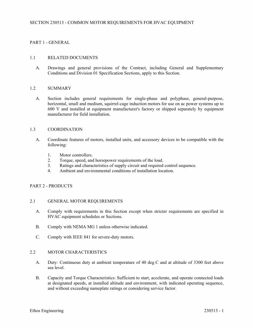
SECTION 230513 - COMMON MOTOR REQUIREMENTS FOR HVAC EQUIPMENT
Ethos Engineering 230513 - 1
PART 1 - GENERAL
1.1 RELATED DOCUMENTS
A. Drawings and general provisions of the Contract, including General and Supplementary Conditions and Division 01 Specification Sections, apply to this Section.
1.2 SUMMARY
A. Section includes general requirements for single-phase and polyphase, general-purpose, horizontal, small and medium, squirrel-cage induction motors for use on ac power systems up to 600 V and installed at equipment manufacturer's factory or shipped separately by equipment manufacturer for field installation.
1.3 COORDINATION
A. Coordinate features of motors, installed units, and accessory devices to be compatible with the following:
1. Motor controllers. 2. Torque, speed, and horsepower requirements of the load. 3. Ratings and characteristics of supply circuit and required control sequence. 4. Ambient and environmental conditions of installation location.
PART 2 - PRODUCTS
2.1 GENERAL MOTOR REQUIREMENTS
A. Comply with requirements in this Section except when stricter requirements are specified in HVAC equipment schedules or Sections.
B. Comply with NEMA MG 1 unless otherwise indicated.
C. Comply with IEEE 841 for severe-duty motors.
2.2 MOTOR CHARACTERISTICS
A. Duty: Continuous duty at ambient temperature of 40 deg C and at altitude of 3300 feet above sea level.
B. Capacity and Torque Characteristics: Sufficient to start, accelerate, and operate connected loads at designated speeds, at installed altitude and environment, with indicated operating sequence, and without exceeding nameplate ratings or considering service factor.
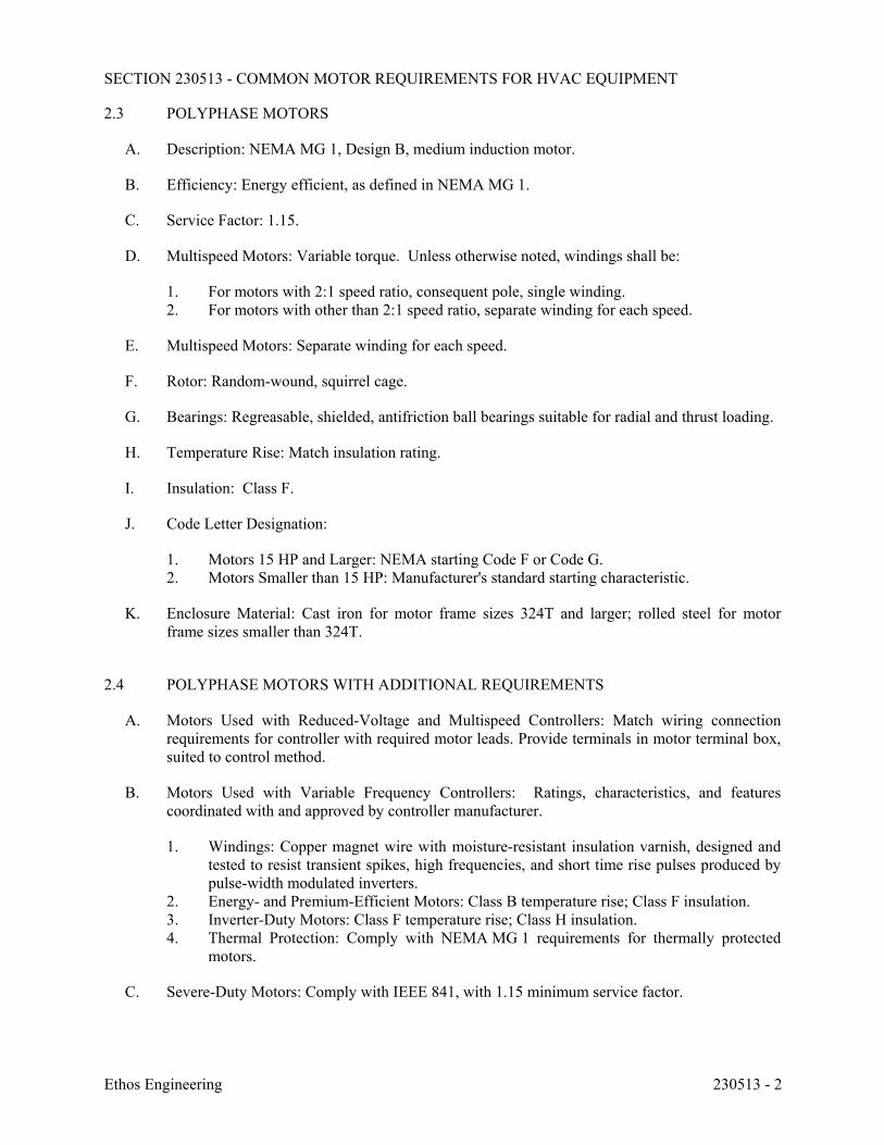
SECTION 230513 - COMMON MOTOR REQUIREMENTS FOR HVAC EQUIPMENT
Ethos Engineering 230513 - 2
2.3 POLYPHASE MOTORS
A. Description: NEMA MG 1, Design B, medium induction motor.
B. Efficiency: Energy efficient, as defined in NEMA MG 1.
C. Service Factor: 1.15.
D. Multispeed Motors: Variable torque. Unless otherwise noted, windings shall be:
1. For motors with 2:1 speed ratio, consequent pole, single winding. 2. For motors with other than 2:1 speed ratio, separate winding for each speed.
E. Multispeed Motors: Separate winding for each speed.
F. Rotor: Random-wound, squirrel cage.
G. Bearings: Regreasable, shielded, antifriction ball bearings suitable for radial and thrust loading.
H. Temperature Rise: Match insulation rating.
I. Insulation: Class F.
J. Code Letter Designation:
1. Motors 15 HP and Larger: NEMA starting Code F or Code G. 2. Motors Smaller than 15 HP: Manufacturer's standard starting characteristic.
K. Enclosure Material: Cast iron for motor frame sizes 324T and larger; rolled steel for motor frame sizes smaller than 324T.
2.4 POLYPHASE MOTORS WITH ADDITIONAL REQUIREMENTS
A. Motors Used with Reduced-Voltage and Multispeed Controllers: Match wiring connection requirements for controller with required motor leads. Provide terminals in motor terminal box, suited to control method.
B. Motors Used with Variable Frequency Controllers: Ratings, characteristics, and features coordinated with and approved by controller manufacturer.
1. Windings: Copper magnet wire with moisture-resistant insulation varnish, designed and tested to resist transient spikes, high frequencies, and short time rise pulses produced by pulse-width modulated inverters.
2. Energy- and Premium-Efficient Motors: Class B temperature rise; Class F insulation. 3. Inverter-Duty Motors: Class F temperature rise; Class H insulation. 4. Thermal Protection: Comply with NEMA MG 1 requirements for thermally protected
motors.
C. Severe-Duty Motors: Comply with IEEE 841, with 1.15 minimum service factor.
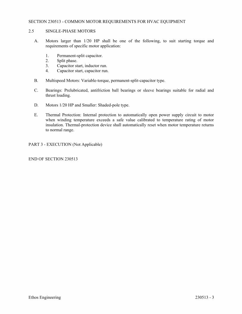
SECTION 230513 - COMMON MOTOR REQUIREMENTS FOR HVAC EQUIPMENT
Ethos Engineering 230513 - 3
2.5 SINGLE-PHASE MOTORS
A. Motors larger than 1/20 HP shall be one of the following, to suit starting torque and requirements of specific motor application:
1. Permanent-split capacitor. 2. Split phase. 3. Capacitor start, inductor run. 4. Capacitor start, capacitor run.
B. Multispeed Motors: Variable-torque, permanent-split-capacitor type.
C. Bearings: Prelubricated, antifriction ball bearings or sleeve bearings suitable for radial and thrust loading.
D. Motors 1/20 HP and Smaller: Shaded-pole type.
E. Thermal Protection: Internal protection to automatically open power supply circuit to motor when winding temperature exceeds a safe value calibrated to temperature rating of motor insulation. Thermal-protection device shall automatically reset when motor temperature returns to normal range.
PART 3 - EXECUTION (Not Applicable)
END OF SECTION 230513
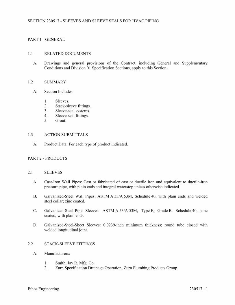
SECTION 230517 - SLEEVES AND SLEEVE SEALS FOR HVAC PIPING
Ethos Engineering 230517 - 1
PART 1 - GENERAL
1.1 RELATED DOCUMENTS
A. Drawings and general provisions of the Contract, including General and Supplementary Conditions and Division 01 Specification Sections, apply to this Section.
1.2 SUMMARY
A. Section Includes:
1. Sleeves. 2. Stack-sleeve fittings. 3. Sleeve-seal systems. 4. Sleeve-seal fittings. 5. Grout.
1.3 ACTION SUBMITTALS
A. Product Data: For each type of product indicated.
PART 2 - PRODUCTS
2.1 SLEEVES
A. Cast-Iron Wall Pipes: Cast or fabricated of cast or ductile iron and equivalent to ductile-iron pressure pipe, with plain ends and integral waterstop unless otherwise indicated.
B. Galvanized-Steel Wall Pipes: ASTM A 53/A 53M, Schedule 40, with plain ends and welded steel collar; zinc coated.
C. Galvanized-Steel-Pipe Sleeves: ASTM A 53/A 53M, Type E, Grade B, Schedule 40, zinc coated, with plain ends.
D. Galvanized-Steel-Sheet Sleeves: 0.0239-inch minimum thickness; round tube closed with welded longitudinal joint.
2.2 STACK-SLEEVE FITTINGS
A. Manufacturers:
1. Smith, Jay R. Mfg. Co. 2. Zurn Specification Drainage Operation; Zurn Plumbing Products Group.
SECTION 230517 - SLEEVES AND SLEEVE SEALS FOR HVAC PIPING
Ethos Engineering 230517 - 2
B. Description: Manufactured, cast-iron sleeve with integral clamping flange. Include clamping ring, bolts, and nuts for membrane flashing.
1. Underdeck Clamp: Clamping ring with setscrews.
2.3 SLEEVE-SEAL SYSTEMS
A. Manufacturers:
1. Advance Products & Systems, Inc. 2. CALPICO, Inc. 3. Metraflex Company (The). 4. Pipeline Seal and Insulator, Inc. 5. Proco Products, Inc.
B. Description: Modular sealing-element unit, designed for field assembly, for filling annular space between piping and sleeve.
1. Sealing Elements: EPDM-rubber interlocking links shaped to fit surface of pipe. Include type and number required for pipe material and size of pipe.
2. Pressure Plates: Carbon steel. 3. Connecting Bolts and Nuts: Carbon steel, with corrosion-resistant coating, of length
required to secure pressure plates to sealing elements.
2.4 SLEEVE-SEAL FITTINGS
A. Manufacturers:
1. Presealed Systems.
B. Description: Manufactured plastic, sleeve-type, waterstop assembly made for imbedding in concrete slab or wall. Unit has plastic or rubber waterstop collar with center opening to match piping OD.
2.5 GROUT
A. Standard: ASTM C 1107/C 1107M, Grade B, post-hardening and volume-adjusting, dry, hydraulic-cement grout.
B. Characteristics: Nonshrink; recommended for interior and exterior applications.
C. Design Mix: 5000-psi, 28-day compressive strength.
D. Packaging: Premixed and factory packaged.
SECTION 230517 - SLEEVES AND SLEEVE SEALS FOR HVAC PIPING
Ethos Engineering 230517 - 3
PART 3 - EXECUTION
3.1 SLEEVE INSTALLATION
A. Install sleeves for piping passing through penetrations in floors, partitions, roofs, and walls.
B. For sleeves that will have sleeve-seal system installed, select sleeves of size large enough to provide 1-inch annular clear space between piping and concrete slabs and walls.
C. Install sleeves in concrete floors, concrete roof slabs, and concrete walls as new slabs and walls are constructed. 1. Cut sleeves to length for mounting flush with both surfaces.
a. Exception: Extend sleeves installed in floors of mechanical equipment areas or other wet areas 2 inches above finished floor level.
2. Using grout, seal the space outside of sleeves in slabs and walls without sleeve-seal system.
D. Install sleeves for pipes passing through interior partitions.
1. Cut sleeves to length for mounting flush with both surfaces. 2. Install sleeves that are large enough to provide 1/4-inch annular clear space between
sleeve and pipe or pipe insulation. 3. Seal annular space between sleeve and piping or piping insulation; use joint sealants
appropriate for size, depth, and location of joint. Comply with requirements for sealants specified in Section 079200 "Joint Sealants."
E. Fire-Barrier Penetrations: Maintain indicated fire rating of walls, partitions, ceilings, and floors at pipe penetrations. Seal pipe penetrations with firestop materials. Comply with requirements for firestopping specified in Section 078413 "Penetration Firestopping."
3.2 STACK-SLEEVE-FITTING INSTALLATION
A. Install stack-sleeve fittings in new slabs as slabs are constructed.
1. Install fittings that are large enough to provide 1/4-inch annular clear space between sleeve and pipe or pipe insulation.
2. Secure flashing between clamping flanges for pipes penetrating floors with membrane waterproofing. Comply with requirements for flashing specified in Section 076200 "Sheet Metal Flashing and Trim."
3. Install section of cast-iron soil pipe to extend sleeve to 2 inches above finished floor level.
4. Extend cast-iron sleeve fittings below floor slab as required to secure clamping ring if ring is specified.
5. Using grout, seal the space around outside of stack-sleeve fittings.
SECTION 230517 - SLEEVES AND SLEEVE SEALS FOR HVAC PIPING
Ethos Engineering 230517 - 4
B. Fire-Barrier Penetrations: Maintain indicated fire rating of floors at pipe penetrations. Seal pipe penetrations with firestop materials. Comply with requirements for firestopping specified in Section 078413 "Penetration Firestopping."
3.3 SLEEVE-SEAL-SYSTEM INSTALLATION
A. Install sleeve-seal systems in sleeves in exterior concrete walls and slabs-on-grade at service piping entries into building.
B. Select type, size, and number of sealing elements required for piping material and size and for sleeve ID or hole size. Position piping in center of sleeve. Center piping in penetration, assemble sleeve-seal system components, and install in annular space between piping and sleeve. Tighten bolts against pressure plates that cause sealing elements to expand and make a watertight seal.
3.4 SLEEVE-SEAL-FITTING INSTALLATION
A. Install sleeve-seal fittings in new walls and slabs as they are constructed.
B. Assemble fitting components of length to be flush with both surfaces of concrete slabs and walls. Position waterstop flange to be centered in concrete slab or wall.
C. Secure nailing flanges to concrete forms.
D. Using grout, seal the space around outside of sleeve-seal fittings.
3.5 SLEEVE AND SLEEVE-SEAL SCHEDULE
A. Use sleeves and sleeve seals for the following piping-penetration applications: 1. Exterior Concrete Walls above Grade: Cast-iron wall sleeves. 2. Exterior Concrete Walls below Grade: Cast-iron wall sleeves with sleeve-seal system.
Select sleeve size to allow for 1-inch annular clear space between piping and sleeve for installing sleeve-seal system.
3. Concrete Slabs-on-Grade: Cast-iron wall sleeves with sleeve-seal system. Select sleeve size to allow for 1-inch annular clear space between piping and sleeve for installing sleeve-seal system.
4. Concrete Slabs above Grade: Galvanized-steel-pipe sleeves. 5. Interior Partitions: Galvanized-steel-pipe sleeves.
END OF SECTION 230517
SECTION 230518 - ESCUTCHEONS FOR HVAC PIPING
Ethos Engineering 230518 - 1
PART 1 - GENERAL
1.1 RELATED DOCUMENTS
A. Drawings and general provisions of the Contract, including General and Supplementary Conditions and Division 01 Specification Sections, apply to this Section.
1.2 SUMMARY
A. Section Includes:
1. Escutcheons. 2. Floor plates.
1.3 ACTION SUBMITTALS
A. Product Data: For each type of product indicated.
PART 2 - PRODUCTS
2.1 ESCUTCHEONS
A. One-Piece, Cast-Brass Type: With polished, chrome-plated and rough-brass finish and setscrew fastener.
B. One-Piece, Deep-Pattern Type: Deep-drawn, box-shaped brass with chrome-plated finish and spring-clip fasteners.
C. One-Piece, Stamped-Steel Type: With chrome-plated finish and spring-clip fasteners.
D. Split-Casting Brass Type: With polished, chrome-plated and rough-brass finish and with concealed hinge and setscrew.
2.2 FLOOR PLATES
A. One-Piece Floor Plates: Cast-iron flange with holes for fasteners.
B. Split-Casting Floor Plates: Cast brass with concealed hinge.
SECTION 230518 - ESCUTCHEONS FOR HVAC PIPING
Ethos Engineering 230518 - 2
PART 3 - EXECUTION
3.1 INSTALLATION
A. Install escutcheons for piping penetrations of walls, ceilings, and finished floors.
B. Install escutcheons with ID to closely fit around pipe, tube, and insulation of piping and with OD that completely covers opening.
1. Escutcheons for New Piping:
a. Piping with Fitting or Sleeve Protruding from Wall: One-piece, deep-pattern type. b. Insulated Piping: One-piece, stamped-steel type. c. Bare Piping at Wall and Floor Penetrations in Finished Spaces: One-piece, cast-
brass type with polished, chrome-plated finish. d. Bare Piping at Ceiling Penetrations in Finished Spaces: One-piece, cast-brass or
split-casting brass type with polished, chrome-plated finish. e. Bare Piping in Unfinished Service Spaces: One-piece, cast-brass type with rough-
brass finish. f. Bare Piping in Equipment Rooms: One-piece, cast-brass type with rough-brass
finish.
2. Escutcheons for Existing Piping: a. Insulated Piping: Split-plate, stamped-steel type with concealed hinge. b. Bare Piping at Wall and Floor Penetrations in Finished Spaces: Split-casting brass
type with polished, chrome-plated finish. c. Bare Piping at Wall and Floor Penetrations in Finished Spaces: Split-plate,
stamped-steel type with concealed hinge. d. Bare Piping at Ceiling Penetrations in Finished Spaces: Split-casting brass type
with polished, chrome-plated finish. e. Bare Piping at Ceiling Penetrations in Finished Spaces: Split-plate, stamped-steel
type with concealed hinge. f. Bare Piping in Unfinished Service Spaces: Split-casting brass type with rough-
brass finish. g. Bare Piping in Equipment Rooms: Split-casting brass type with rough-brass finish.
C. Install floor plates for piping penetrations of equipment-room floors.
D. Install floor plates with ID to closely fit around pipe, tube, and insulation of piping and with OD that completely covers opening. 1. New Piping: One-piece, floor-plate type. 2. Existing Piping: Split-casting, floor-plate type.
3.2 FIELD QUALITY CONTROL
A. Replace broken and damaged escutcheons and floor plates using new materials.
END OF SECTION 230518
SECTION 230529 - HANGERS AND SUPPORTS FOR HVAC PIPING AND EQUIPMENT
Ethos Engineering 230529 - 1
PART 1 - GENERAL
1.1 RELATED DOCUMENTS
A. Drawings and general provisions of the Contract, including General and Supplementary Conditions and Division 01 Specification Sections, apply to this Section.
1.2 SUMMARY
A. Section Includes:
1. Metal pipe hangers and supports. 2. Trapeze pipe hangers. 3. Metal framing systems. 4. Thermal-hanger shield inserts. 5. Fastener systems. 6. Pipe stands. 7. Equipment supports.
B. Related Sections:
1. Section 055000 "Metal Fabrications" for structural-steel shapes and plates for trapeze hangers for pipe and equipment supports.
2. Section 230516 "Expansion Fittings and Loops for HVAC Piping" for pipe guides and anchors.
3. Section 230548.13 "Vibration Controls for HVAC" for vibration isolation devices. 4. Section 233113 "Metal Ducts" and Section 233116 "Nonmetal Ducts" for duct hangers
and supports.
1.3 DEFINITIONS
A. MSS: Manufacturers Standardization Society of The Valve and Fittings Industry Inc.
1.4 PERFORMANCE REQUIREMENTS
A. Delegated Design: Design trapeze pipe hangers and equipment supports, including comprehensive engineering analysis by a qualified professional engineer, using performance requirements and design criteria indicated.
B. Structural Performance: Hangers and supports for HVAC piping and equipment shall withstand the effects of gravity loads and stresses within limits and under conditions indicated according to ASCE/SEI 7.
1. Design supports for multiple pipes, including pipe stands, capable of supporting combined weight of supported systems, system contents, and test water.
SECTION 230529 - HANGERS AND SUPPORTS FOR HVAC PIPING AND EQUIPMENT
Ethos Engineering 230529 - 2
2. Design equipment supports capable of supporting combined operating weight of supported equipment and connected systems and components.
1.5 ACTION SUBMITTALS
A. Product Data: For each type of product indicated.
B. Shop Drawings: Show fabrication and installation details and include calculations for the following; include Product Data for components:
1. Trapeze pipe hangers. 2. Metal framing systems. 3. Pipe stands. 4. Equipment supports.
C. Delegated-Design Submittal: For trapeze hangers indicated to comply with performance requirements and design criteria, including analysis data signed and sealed by the qualified professional engineer responsible for their preparation.
1. Detail fabrication and assembly of trapeze hangers. 2. Design Calculations: Calculate requirements for designing trapeze hangers.
1.6 INFORMATIONAL SUBMITTALS
A. Welding certificates.
1.7 QUALITY ASSURANCE
A. Structural Steel Welding Qualifications: Qualify procedures and personnel according to AWS D1.1/D1.1M, "Structural Welding Code - Steel."
B. Pipe Welding Qualifications: Qualify procedures and operators according to ASME Boiler and Pressure Vessel Code.
PART 2 - PRODUCTS
2.1 METAL PIPE HANGERS AND SUPPORTS
A. Carbon-Steel Pipe Hangers and Supports:
1. Description: MSS SP-58, Types 1 through 58, factory-fabricated components. 2. Galvanized Metallic Coatings: Pregalvanized or hot dipped.
SECTION 230529 - HANGERS AND SUPPORTS FOR HVAC PIPING AND EQUIPMENT
Ethos Engineering 230529 - 3
2.2 TRAPEZE PIPE HANGERS
A. Description: MSS SP-69, Type 59, shop- or field-fabricated pipe-support assembly made from structural carbon-steel shapes with MSS SP-58 carbon-steel hanger rods, nuts, saddles, and U-bolts.
2.3 METAL FRAMING SYSTEMS
A. MFMA Manufacturer Metal Framing Systems: 1. Manufacturers:
a. Allied Tube & Conduit. b. Cooper B-Line, Inc. c. Flex-Strut Inc. d. GS Metals Corp. e. Thomas & Betts Corporation. f. Unistrut Corporation; Tyco International, Ltd. g. Wesanco, Inc.
2. Description: Shop- or field-fabricated pipe-support assembly for supporting multiple parallel pipes.
3. Standard: MFMA-4. 4. Channels: Continuous slotted steel channel with inturned lips. 5. Channel Nuts: Formed or stamped steel nuts or other devices designed to fit into channel
slot and, when tightened, prevent slipping along channel. 6. Hanger Rods: Continuous-thread rod, nuts, and washer made of carbon steel. 7. Metallic Coating: Hot-dipped galvanized. 8. Paint Coating: Epoxy.
2.4 THERMAL-HANGER SHIELD INSERTS
A. Manufacturers:
1. Carpenter & Paterson, Inc. 2. ERICO/Michigan Hanger Co. 3. PHS Industries, Inc. 4. Pipe Shields, Inc. 5. Rilco Manufacturing Company, Inc. 6. Value Engineered Products, Inc.
B. Insulation-Insert Material for Piping: ASTM C 552, Type II cellular glass with 100-psig minimum compressive strength and vapor barrier.
C. For Trapeze or Clamped Systems: Insert and shield shall cover entire circumference of pipe.
D. For Clevis or Band Hangers: Insert and shield shall cover lower 180 degrees of pipe.
E. Insert Length: Extend 2 inches beyond sheet metal shield for piping operating below ambient air temperature.
SECTION 230529 - HANGERS AND SUPPORTS FOR HVAC PIPING AND EQUIPMENT
Ethos Engineering 230529 - 4
2.5 FASTENER SYSTEMS
A. Mechanical-Expansion Anchors: Insert-wedge-type, stainless- steel anchors, for use in hardened portland cement concrete; with pull-out, tension, and shear capacities appropriate for supported loads and building materials where used.
2.6 PIPE STANDS
A. General Requirements for Pipe Stands: Shop- or field-fabricated assemblies made of manufactured corrosion-resistant components to support roof-mounted piping.
B. Compact Pipe Stand: One-piece plastic unit with integral-rod roller, pipe clamps, or V-shaped cradle to support pipe, for roof installation without membrane penetration.
C. Low-Type, Single-Pipe Stand: One-piece stainless-steel base unit with plastic roller, for roof installation without membrane penetration.
D. High-Type, Single-Pipe Stand:
1. Description: Assembly of base, vertical and horizontal members, and pipe support, for roof installation without membrane penetration.
2. Base: Plastic. 3. Vertical Members: Two or more cadmium-plated-steel or stainless-steel, continuous-
thread rods. 4. Horizontal Member: Cadmium-plated-steel or stainless-steel rod with plastic or stainless-
steel, roller-type pipe support.
E. High-Type, Multiple-Pipe Stand:
1. Description: Assembly of bases, vertical and horizontal members, and pipe supports, for roof installation without membrane penetration.
2. Bases: One or more; plastic. 3. Vertical Members: Two or more protective-coated-steel channels. 4. Horizontal Member: Protective-coated-steel channel. 5. Pipe Supports: Galvanized-steel, clevis-type pipe hangers.
F. Curb-Mounted-Type Pipe Stands: Shop- or field-fabricated pipe supports made from structural-steel shapes, continuous-thread rods, and rollers, for mounting on permanent stationary roof curb.
2.7 EQUIPMENT SUPPORTS
A. Description: Welded, shop- or field-fabricated equipment support made from structural carbon-steel shapes.
2.8 MISCELLANEOUS MATERIALS
A. Structural Steel: ASTM A 36/A 36M, carbon-steel plates, shapes, and bars; black and galvanized.
SECTION 230529 - HANGERS AND SUPPORTS FOR HVAC PIPING AND EQUIPMENT
Ethos Engineering 230529 - 5
B. Grout: ASTM C 1107, factory-mixed and -packaged, dry, hydraulic-cement, nonshrink and nonmetallic grout; suitable for interior and exterior applications.
1. Properties: Nonstaining, noncorrosive, and nongaseous. 2. Design Mix: 5000-psi, 28-day compressive strength.
PART 3 - EXECUTION
3.1 HANGER AND SUPPORT INSTALLATION
A. Metal Pipe-Hanger Installation: Comply with MSS SP-69 and MSS SP-89. Install hangers, supports, clamps, and attachments as required to properly support piping from the building structure.
B. Metal Trapeze Pipe-Hanger Installation: Comply with MSS SP-69 and MSS SP-89. Arrange for grouping of parallel runs of horizontal piping, and support together on field-fabricated trapeze pipe hangers.
1. Pipes of Various Sizes: Support together and space trapezes for smallest pipe size or install intermediate supports for smaller diameter pipes as specified for individual pipe hangers.
2. Field fabricate from ASTM A 36/A 36M, carbon-steel shapes selected for loads being supported. Weld steel according to AWS D1.1/D1.1M.
C. Metal Framing System Installation: Arrange for grouping of parallel runs of piping, and support together on field-assembled metal framing systems.
D. Thermal-Hanger Shield Installation: Install in pipe hanger or shield for insulated piping.
E. Fastener System Installation: 1. Install mechanical-expansion anchors in concrete after concrete is placed and completely
cured. Install fasteners according to manufacturer's written instructions.
F. Pipe Stand Installation:
1. Pipe Stand Types except Curb-Mounted Type: Assemble components and mount on smooth roof surface. Do not penetrate roof membrane.
2. Curb-Mounted-Type Pipe Stands: Assemble components or fabricate pipe stand and mount on permanent, stationary roof curb. See Section 077200 "Roof Accessories" for curbs.
G. Install hangers and supports complete with necessary attachments, inserts, bolts, rods, nuts, washers, and other accessories.
H. Equipment Support Installation: Fabricate from welded-structural-steel shapes.
I. Install hangers and supports to allow controlled thermal and seismic movement of piping systems, to permit freedom of movement between pipe anchors, and to facilitate action of expansion joints, expansion loops, expansion bends, and similar units.
SECTION 230529 - HANGERS AND SUPPORTS FOR HVAC PIPING AND EQUIPMENT
Ethos Engineering 230529 - 6
J. Install lateral bracing with pipe hangers and supports to prevent swaying.
K. Install building attachments within concrete slabs or attach to structural steel. Install additional attachments at concentrated loads, including valves, flanges, and strainers, NPS 2-1/2 and larger and at changes in direction of piping. Install concrete inserts before concrete is placed; fasten inserts to forms and install reinforcing bars through openings at top of inserts.
L. Load Distribution: Install hangers and supports so that piping live and dead loads and stresses from movement will not be transmitted to connected equipment.
M. Pipe Slopes: Install hangers and supports to provide indicated pipe slopes and to not exceed maximum pipe deflections allowed by ASME B31.9 for building services piping.
N. Insulated Piping:
1. Attach clamps and spacers to piping.
a. Piping Operating above Ambient Air Temperature: Clamp may project through insulation.
b. Piping Operating below Ambient Air Temperature: Use thermal-hanger shield insert with clamp sized to match OD of insert.
c. Do not exceed pipe stress limits allowed by ASME B31.9 for building services piping.
2. Install MSS SP-58, Type 39, protection saddles if insulation without vapor barrier is indicated. Fill interior voids with insulation that matches adjoining insulation.
a. Option: Thermal-hanger shield inserts may be used. Include steel weight-distribution plate for pipe NPS 4 and larger if pipe is installed on rollers.
3. Install MSS SP-58, Type 40, protective shields on cold piping with vapor barrier. Shields shall span an arc of 180 degrees.
a. Option: Thermal-hanger shield inserts may be used. Include steel weight-distribution plate for pipe NPS 4 and larger if pipe is installed on rollers.
4. Shield Dimensions for Pipe: Not less than the following:
a. NPS 1/4 to NPS 3-1/2: 12 inches long and 0.048 inch thick. b. NPS 4: 12 inches long and 0.06 inch thick. c. NPS 5 and NPS 6: 18 inches long and 0.06 inch thick. d. NPS 8 to NPS 14: 24 inches long and 0.075 inch thick. e. NPS 16 to NPS 24: 24 inches long and 0.105 inch thick.
5. Pipes NPS 8 and Larger: Include wood or reinforced calcium-silicate-insulation inserts of length at least as long as protective shield.
6. Thermal-Hanger Shields: Install with insulation same thickness as piping insulation.
SECTION 230529 - HANGERS AND SUPPORTS FOR HVAC PIPING AND EQUIPMENT
Ethos Engineering 230529 - 7
3.2 EQUIPMENT SUPPORTS
A. Fabricate structural-steel stands to suspend equipment from structure overhead or to support equipment above floor.
B. Grouting: Place grout under supports for equipment and make bearing surface smooth.
C. Provide lateral bracing, to prevent swaying, for equipment supports.
3.3 METAL FABRICATIONS
A. Cut, drill, and fit miscellaneous metal fabrications for trapeze pipe hangers and equipment supports.
B. Fit exposed connections together to form hairline joints. Field weld connections that cannot be shop welded because of shipping size limitations.
C. Field Welding: Comply with AWS D1.1/D1.1M procedures for shielded, metal arc welding; appearance and quality of welds; and methods used in correcting welding work; and with the following:
1. Use materials and methods that minimize distortion and develop strength and corrosion resistance of base metals.
2. Obtain fusion without undercut or overlap. 3. Remove welding flux immediately. 4. Finish welds at exposed connections so no roughness shows after finishing and so
contours of welded surfaces match adjacent contours.
3.4 ADJUSTING
A. Hanger Adjustments: Adjust hangers to distribute loads equally on attachments and to achieve indicated slope of pipe.
B. Trim excess length of continuous-thread hanger and support rods to 1-1/2 inches.
3.5 PAINTING
A. Touchup: Clean field welds and abraded areas of shop paint. Paint exposed areas immediately after erecting hangers and supports. Use same materials as used for shop painting. Comply with SSPC-PA 1 requirements for touching up field-painted surfaces.
1. Apply paint by brush or spray to provide a minimum dry film thickness of 2.0 mils.
B. Touchup: Cleaning and touchup painting of field welds, bolted connections, and abraded areas of shop paint on miscellaneous metal are specified in Division 09 Sections.
C. Galvanized Surfaces: Clean welds, bolted connections, and abraded areas and apply galvanizing-repair paint to comply with ASTM A 780.
SECTION 230529 - HANGERS AND SUPPORTS FOR HVAC PIPING AND EQUIPMENT
Ethos Engineering 230529 - 8
3.6 HANGER AND SUPPORT SCHEDULE
A. Specific hanger and support requirements are in Sections specifying piping systems and equipment.
B. Comply with MSS SP-69 for pipe-hanger selections and applications that are not specified in piping system Sections.
C. Use hangers and supports with galvanized metallic coatings for piping and equipment that will not have field-applied finish.
D. Use nonmetallic coatings on attachments for electrolytic protection where attachments are in direct contact with copper tubing.
E. Use carbon-steel pipe hangers and supports metal trapeze pipe hangers and attachments for general service applications.
F. Use stainless-steel pipe hangers and stainless-steel attachments for hostile environment applications.
G. Use copper-plated pipe hangers and copper attachments for copper piping and tubing.
H. Use padded hangers for piping that is subject to scratching.
I. Use thermal-hanger shield inserts for insulated piping and tubing.
J. Horizontal-Piping Hangers and Supports: Unless otherwise indicated and except as specified in piping system Sections, install the following types:
1. Adjustable, Steel Clevis Hangers (MSS Type 1): For suspension of noninsulated or insulated, stationary pipes NPS 1/2 to NPS 30.
2. Pipe Saddle Supports (MSS Type 36): For support of pipes NPS 4 to NPS 36, with steel-pipe base stanchion support and cast-iron floor flange or carbon-steel plate.
3. Pipe Stanchion Saddles (MSS Type 37): For support of pipes NPS 4 to NPS 36, with steel-pipe base stanchion support and cast-iron floor flange or carbon-steel plate, and with U-bolt to retain pipe.
4. Adjustable Roller Hangers (MSS Type 43): For suspension of pipes NPS 2-1/2 to NPS 24, from single rod if horizontal movement caused by expansion and contraction might occur.
5. Complete Pipe Rolls (MSS Type 44): For support of pipes NPS 2 to NPS 42 if longitudinal movement caused by expansion and contraction might occur but vertical adjustment is not necessary.
6. Pipe Roll and Plate Units (MSS Type 45): For support of pipes NPS 2 to NPS 24 if small horizontal movement caused by expansion and contraction might occur and vertical adjustment is not necessary.
7. Adjustable Pipe Roll and Base Units (MSS Type 46): For support of pipes NPS 2 to NPS 30 if vertical and lateral adjustment during installation might be required in addition to expansion and contraction.
K. Vertical-Piping Clamps: Unless otherwise indicated and except as specified in piping system Sections, install the following types:
SECTION 230529 - HANGERS AND SUPPORTS FOR HVAC PIPING AND EQUIPMENT
Ethos Engineering 230529 - 9
1. Extension Pipe or Riser Clamps (MSS Type 8): For support of pipe risers NPS 3/4 to NPS 24.
2. Carbon- or Alloy-Steel Riser Clamps (MSS Type 42): For support of pipe risers NPS 3/4 to NPS 24 if longer ends are required for riser clamps.
L. Hanger-Rod Attachments: Unless otherwise indicated and except as specified in piping system Sections, install the following types:
1. Steel Turnbuckles (MSS Type 13): For adjustment up to 6 inches for heavy loads. 2. Steel Clevises (MSS Type 14): For 120 to 450 deg F piping installations. 3. Swivel Turnbuckles (MSS Type 15): For use with MSS Type 11, split pipe rings. 4. Malleable-Iron Sockets (MSS Type 16): For attaching hanger rods to various types of
building attachments. 5. Steel Weldless Eye Nuts (MSS Type 17): For 120 to 450 deg F piping installations.
M. Building Attachments: Unless otherwise indicated and except as specified in piping system Sections, install the following types:
1. Steel or Malleable Concrete Inserts (MSS Type 18): For upper attachment to suspend pipe hangers from concrete ceiling.
2. Top-Beam C-Clamps (MSS Type 19): For use under roof installations with bar-joist construction, to attach to top flange of structural shape.
3. Side-Beam or Channel Clamps (MSS Type 20): For attaching to bottom flange of beams, channels, or angles.
4. Center-Beam Clamps (MSS Type 21): For attaching to center of bottom flange of beams. 5. Welded Beam Attachments (MSS Type 22): For attaching to bottom of beams if loads are
considerable and rod sizes are large. 6. C-Clamps (MSS Type 23): For structural shapes. 7. Top-Beam Clamps (MSS Type 25): For top of beams if hanger rod is required tangent to
flange edge. 8. Side-Beam Clamps (MSS Type 27): For bottom of steel I-beams. 9. Steel-Beam Clamps with Eye Nuts (MSS Type 28): For attaching to bottom of steel I-
beams for heavy loads. 10. Linked-Steel Clamps with Eye Nuts (MSS Type 29): For attaching to bottom of steel I-
beams for heavy loads, with link extensions. 11. Malleable-Beam Clamps with Extension Pieces (MSS Type 30): For attaching to
structural steel. 12. Welded-Steel Brackets: For support of pipes from below or for suspending from above
by using clip and rod. Use one of the following for indicated loads:
a. Light (MSS Type 31): 750 lb. b. Medium (MSS Type 32): 1500 lb. c. Heavy (MSS Type 33): 3000 lb.
13. Horizontal Travelers (MSS Type 58): For supporting piping systems subject to linear horizontal movement where headroom is limited.
N. Saddles and Shields: Unless otherwise indicated and except as specified in piping system Sections, install the following types:
1. Steel-Pipe-Covering Protection Saddles (MSS Type 39): To fill interior voids with insulation that matches adjoining insulation.
SECTION 230529 - HANGERS AND SUPPORTS FOR HVAC PIPING AND EQUIPMENT
Ethos Engineering 230529 - 10
2. Protection Shields (MSS Type 40): Of length recommended in writing by manufacturer to prevent crushing insulation.
3. Thermal-Hanger Shield Inserts: For supporting insulated pipe.
O. Comply with MSS SP-69 for trapeze pipe-hanger selections and applications that are not specified in piping system Sections.
P. Comply with MFMA-103 for metal framing system selections and applications that are not specified in piping system Sections.
Q. Use mechanical-expansion anchors instead of building attachments where required in concrete construction.
END OF SECTION 230529
SECTION 230548.13 - VIBRATION CONTROLS FOR HVAC
Ethos Engineering 230548.13 - 1
PART 1 - GENERAL
1.1 RELATED DOCUMENTS
A. Drawings and general provisions of the Contract, including General and Supplementary Conditions and Division 01 Specification Sections, apply to this Section.
1.2 SUMMARY
A. Section Includes:
1. Elastomeric isolation pads. 2. Elastomeric isolation mounts. 3. Restrained elastomeric isolation mounts. 4. Housed-restrained-spring isolators. 5. Elastomeric hangers. 6. Spring hangers. 7. Vibration isolation equipment bases.
B. Related Requirements:
1. Section 210548.13 "Vibration Controls for Fire Suppression" for devices for fire-suppression equipment and systems.
2. Section 220548.13 "Vibration Controls for Plumbing" for devices for plumbing equipment and systems.
1.3 ACTION SUBMITTALS
A. Product Data: For each type of product.
1. Include rated load, rated deflection, and overload capacity for each vibration isolation device.
2. Illustrate and indicate style, material, strength, fastening provision, and finish for each type and size of vibration isolation device type required.
B. Shop Drawings:
1. Detail fabrication and assembly of equipment bases. Detail fabrication including anchorages and attachments to structure and to supported equipment. Include adjustable motor bases, rails, and frames for equipment mounting.
2. Vibration Isolation Base Details: Detail fabrication including anchorages and attachments to structure and to supported equipment. Include adjustable motor bases, rails, and frames for equipment mounting.
C. Delegated-Design Submittal: For each vibration isolation device.
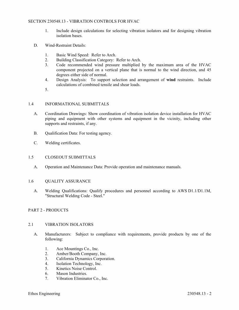
SECTION 230548.13 - VIBRATION CONTROLS FOR HVAC
Ethos Engineering 230548.13 - 2
1. Include design calculations for selecting vibration isolators and for designing vibration isolation bases.
D. Wind-Restraint Details:
1. Basic Wind Speed: Refer to Arch. 2. Building Classification Category: Refer to Arch. 3. Code recommended wind pressure multiplied by the maximum area of the HVAC
component projected on a vertical plane that is normal to the wind direction, and 45 degrees either side of normal.
4. Design Analysis: To support selection and arrangement of wind restraints. Include calculations of combined tensile and shear loads.
5.
1.4 INFORMATIONAL SUBMITTALS
A. Coordination Drawings: Show coordination of vibration isolation device installation for HVAC piping and equipment with other systems and equipment in the vicinity, including other supports and restraints, if any.
B. Qualification Data: For testing agency.
C. Welding certificates.
1.5 CLOSEOUT SUBMITTALS
A. Operation and Maintenance Data: Provide operation and maintenance manuals.
1.6 QUALITY ASSURANCE
A. Welding Qualifications: Qualify procedures and personnel according to AWS D1.1/D1.1M, "Structural Welding Code - Steel."
PART 2 - PRODUCTS
2.1 VIBRATION ISOLATORS
A. Manufacturers: Subject to compliance with requirements, provide products by one of the following:
1. Ace Mountings Co., Inc. 2. Amber/Booth Company, Inc. 3. California Dynamics Corporation. 4. Isolation Technology, Inc. 5. Kinetics Noise Control. 6. Mason Industries. 7. Vibration Eliminator Co., Inc.
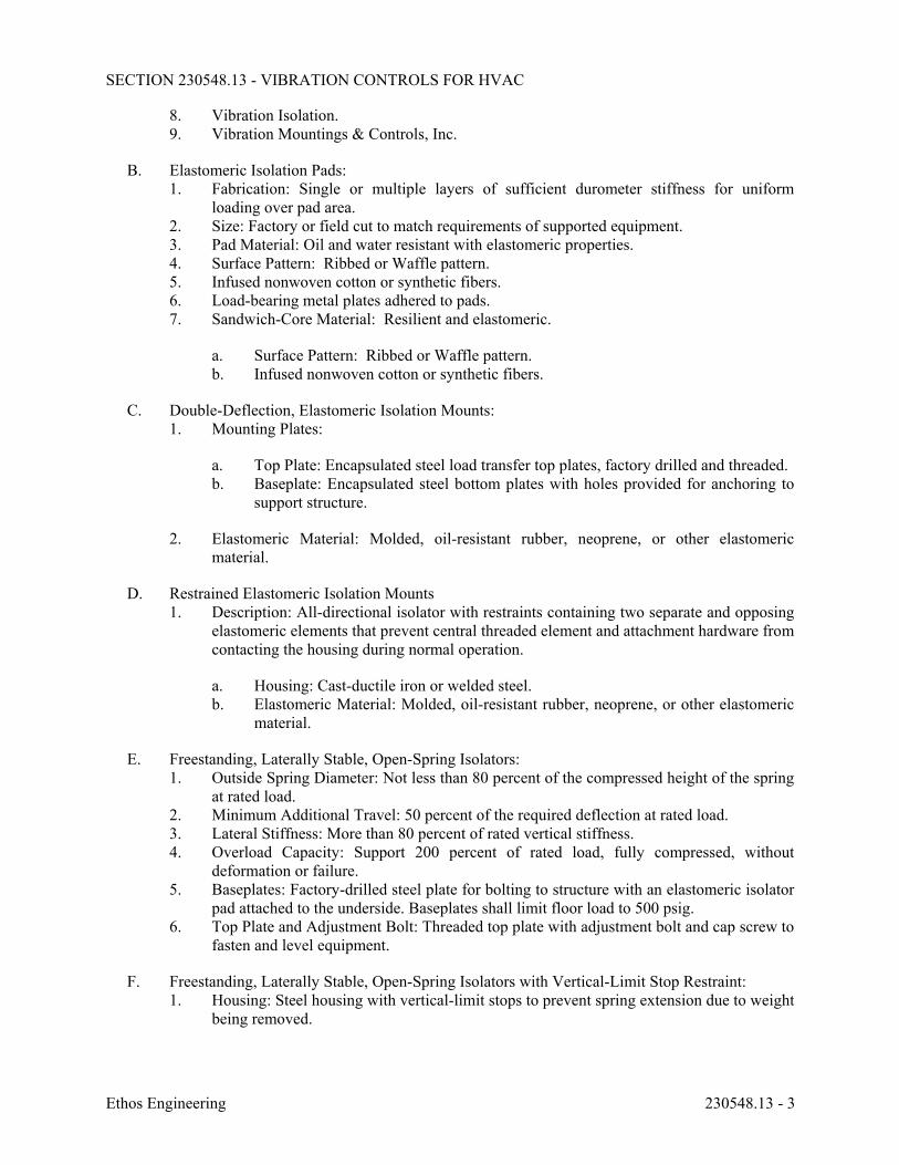
SECTION 230548.13 - VIBRATION CONTROLS FOR HVAC
Ethos Engineering 230548.13 - 3
8. Vibration Isolation. 9. Vibration Mountings & Controls, Inc.
B. Elastomeric Isolation Pads: 1. Fabrication: Single or multiple layers of sufficient durometer stiffness for uniform
loading over pad area. 2. Size: Factory or field cut to match requirements of supported equipment. 3. Pad Material: Oil and water resistant with elastomeric properties. 4. Surface Pattern: Ribbed or Waffle pattern. 5. Infused nonwoven cotton or synthetic fibers. 6. Load-bearing metal plates adhered to pads. 7. Sandwich-Core Material: Resilient and elastomeric.
a. Surface Pattern: Ribbed or Waffle pattern. b. Infused nonwoven cotton or synthetic fibers.
C. Double-Deflection, Elastomeric Isolation Mounts: 1. Mounting Plates:
a. Top Plate: Encapsulated steel load transfer top plates, factory drilled and threaded. b. Baseplate: Encapsulated steel bottom plates with holes provided for anchoring to
support structure.
2. Elastomeric Material: Molded, oil-resistant rubber, neoprene, or other elastomeric material.
D. Restrained Elastomeric Isolation Mounts 1. Description: All-directional isolator with restraints containing two separate and opposing
elastomeric elements that prevent central threaded element and attachment hardware from contacting the housing during normal operation.
a. Housing: Cast-ductile iron or welded steel. b. Elastomeric Material: Molded, oil-resistant rubber, neoprene, or other elastomeric
material.
E. Freestanding, Laterally Stable, Open-Spring Isolators: 1. Outside Spring Diameter: Not less than 80 percent of the compressed height of the spring
at rated load. 2. Minimum Additional Travel: 50 percent of the required deflection at rated load. 3. Lateral Stiffness: More than 80 percent of rated vertical stiffness. 4. Overload Capacity: Support 200 percent of rated load, fully compressed, without
deformation or failure. 5. Baseplates: Factory-drilled steel plate for bolting to structure with an elastomeric isolator
pad attached to the underside. Baseplates shall limit floor load to 500 psig. 6. Top Plate and Adjustment Bolt: Threaded top plate with adjustment bolt and cap screw to
fasten and level equipment.
F. Freestanding, Laterally Stable, Open-Spring Isolators with Vertical-Limit Stop Restraint: 1. Housing: Steel housing with vertical-limit stops to prevent spring extension due to weight
being removed.
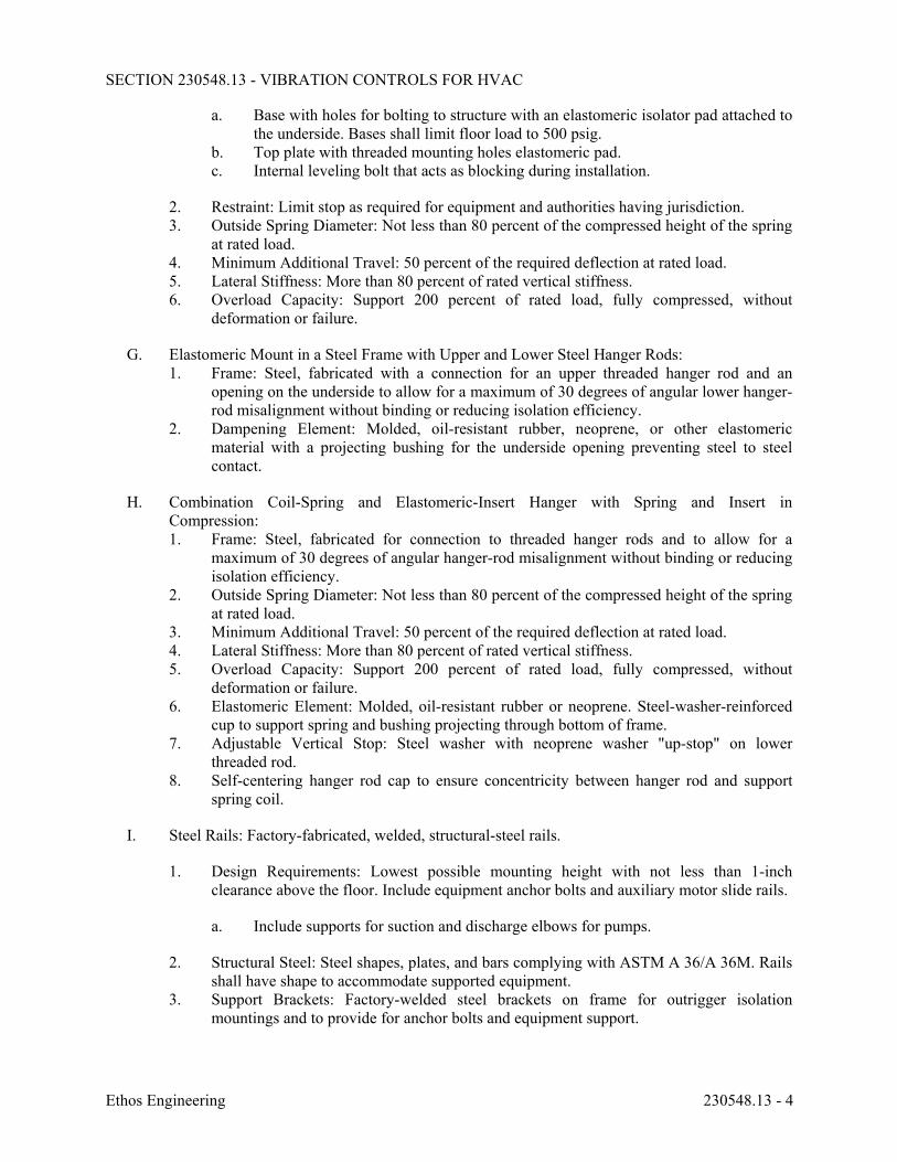
SECTION 230548.13 - VIBRATION CONTROLS FOR HVAC
Ethos Engineering 230548.13 - 4
a. Base with holes for bolting to structure with an elastomeric isolator pad attached to the underside. Bases shall limit floor load to 500 psig.
b. Top plate with threaded mounting holes elastomeric pad. c. Internal leveling bolt that acts as blocking during installation.
2. Restraint: Limit stop as required for equipment and authorities having jurisdiction. 3. Outside Spring Diameter: Not less than 80 percent of the compressed height of the spring
at rated load. 4. Minimum Additional Travel: 50 percent of the required deflection at rated load. 5. Lateral Stiffness: More than 80 percent of rated vertical stiffness. 6. Overload Capacity: Support 200 percent of rated load, fully compressed, without
deformation or failure.
G. Elastomeric Mount in a Steel Frame with Upper and Lower Steel Hanger Rods: 1. Frame: Steel, fabricated with a connection for an upper threaded hanger rod and an
opening on the underside to allow for a maximum of 30 degrees of angular lower hanger-rod misalignment without binding or reducing isolation efficiency.
2. Dampening Element: Molded, oil-resistant rubber, neoprene, or other elastomeric material with a projecting bushing for the underside opening preventing steel to steel contact.
H. Combination Coil-Spring and Elastomeric-Insert Hanger with Spring and Insert in Compression: 1. Frame: Steel, fabricated for connection to threaded hanger rods and to allow for a
maximum of 30 degrees of angular hanger-rod misalignment without binding or reducing isolation efficiency.
2. Outside Spring Diameter: Not less than 80 percent of the compressed height of the spring at rated load.
3. Minimum Additional Travel: 50 percent of the required deflection at rated load. 4. Lateral Stiffness: More than 80 percent of rated vertical stiffness. 5. Overload Capacity: Support 200 percent of rated load, fully compressed, without
deformation or failure. 6. Elastomeric Element: Molded, oil-resistant rubber or neoprene. Steel-washer-reinforced
cup to support spring and bushing projecting through bottom of frame. 7. Adjustable Vertical Stop: Steel washer with neoprene washer "up-stop" on lower
threaded rod. 8. Self-centering hanger rod cap to ensure concentricity between hanger rod and support
spring coil.
I. Steel Rails: Factory-fabricated, welded, structural-steel rails.
1. Design Requirements: Lowest possible mounting height with not less than 1-inch clearance above the floor. Include equipment anchor bolts and auxiliary motor slide rails.
a. Include supports for suction and discharge elbows for pumps.
2. Structural Steel: Steel shapes, plates, and bars complying with ASTM A 36/A 36M. Rails shall have shape to accommodate supported equipment.
3. Support Brackets: Factory-welded steel brackets on frame for outrigger isolation mountings and to provide for anchor bolts and equipment support.
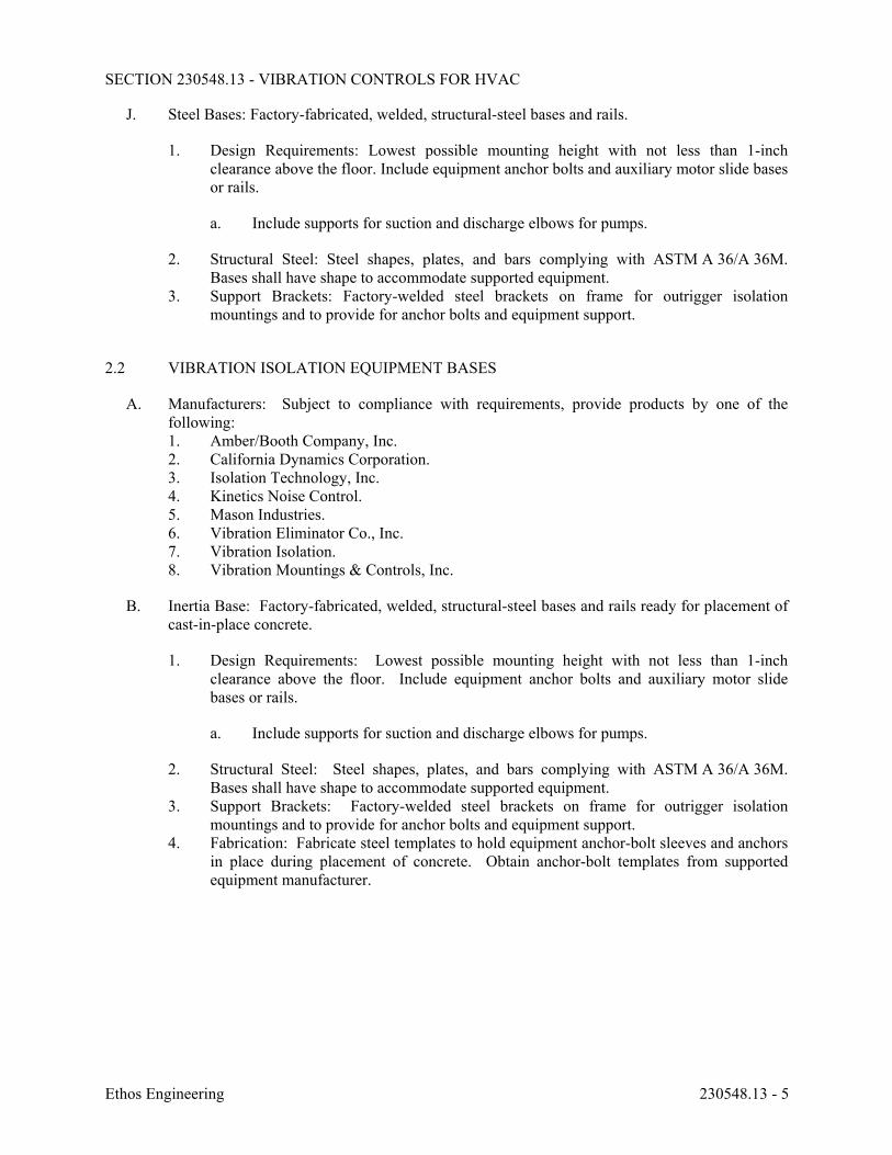
SECTION 230548.13 - VIBRATION CONTROLS FOR HVAC
Ethos Engineering 230548.13 - 5
J. Steel Bases: Factory-fabricated, welded, structural-steel bases and rails.
1. Design Requirements: Lowest possible mounting height with not less than 1-inch clearance above the floor. Include equipment anchor bolts and auxiliary motor slide bases or rails.
a. Include supports for suction and discharge elbows for pumps.
2. Structural Steel: Steel shapes, plates, and bars complying with ASTM A 36/A 36M. Bases shall have shape to accommodate supported equipment.
3. Support Brackets: Factory-welded steel brackets on frame for outrigger isolation mountings and to provide for anchor bolts and equipment support.
2.2 VIBRATION ISOLATION EQUIPMENT BASES
A. Manufacturers: Subject to compliance with requirements, provide products by one of the following: 1. Amber/Booth Company, Inc. 2. California Dynamics Corporation. 3. Isolation Technology, Inc. 4. Kinetics Noise Control. 5. Mason Industries. 6. Vibration Eliminator Co., Inc. 7. Vibration Isolation. 8. Vibration Mountings & Controls, Inc.
B. Inertia Base: Factory-fabricated, welded, structural-steel bases and rails ready for placement of cast-in-place concrete.
1. Design Requirements: Lowest possible mounting height with not less than 1-inch clearance above the floor. Include equipment anchor bolts and auxiliary motor slide bases or rails.
a. Include supports for suction and discharge elbows for pumps.
2. Structural Steel: Steel shapes, plates, and bars complying with ASTM A 36/A 36M. Bases shall have shape to accommodate supported equipment.
3. Support Brackets: Factory-welded steel brackets on frame for outrigger isolation mountings and to provide for anchor bolts and equipment support.
4. Fabrication: Fabricate steel templates to hold equipment anchor-bolt sleeves and anchors in place during placement of concrete. Obtain anchor-bolt templates from supported equipment manufacturer.
SECTION 230548.13 - VIBRATION CONTROLS FOR HVAC
Ethos Engineering 230548.13 - 6
PART 3 - EXECUTION
3.1 EXAMINATION
A. Examine areas and equipment to receive vibration isolation control devices for compliance with requirements for installation tolerances and other conditions affecting performance of the Work.
B. Examine roughing-in of reinforcement and cast-in-place anchors to verify actual locations before installation.
C. Proceed with installation only after unsatisfactory conditions have been corrected.
3.2 APPLICATIONS
A. Multiple Pipe Supports: Secure pipes to trapeze member with clamps approved for application by an agency acceptable to authorities having jurisdiction.
3.3 VIBRATION ISOLATION EQUIPMENT BASES INSTALLATION
A. Coordinate the location of embedded connection hardware with supported equipment attachment and mounting points and with requirements for concrete reinforcement and formwork specified in Division 03 Sections.
3.4 VIBRATION-CONTROL AND WIND-RESTRAINT DEVICE INSTALLATION
A. Comply with requirements in Division 07 Section "Roof Accessories" for installation of roof curbs, equipment supports, and roof penetrations.
B. Install cables so they do not bend across edges of adjacent equipment or building structure.
C. Install bushing assemblies for anchor bolts for floor-mounted equipment, arranged to provide resilient media between anchor bolt and mounting hole in concrete base.
D. Install bushing assemblies for mounting bolts for wall-mounted equipment, arranged to provide resilient media where equipment or equipment-mounting channels are attached to wall.
E. Attachment to Structure: If specific attachment is not indicated, anchor bracing to structure at flanges of beams, at upper truss chords of bar joists, or at concrete members.
F. Drilled-in Anchors: 1. Identify position of reinforcing steel and other embedded items prior to drilling holes for
anchors. Do not damage existing reinforcing or embedded items during coring or drilling. Notify the structural engineer if reinforcing steel or other embedded items are encountered during drilling. Locate and avoid prestressed tendons, electrical and telecommunications conduit, and gas lines.
2. Do not drill holes in concrete or masonry until concrete, mortar, or grout has achieved full design strength.
SECTION 230548.13 - VIBRATION CONTROLS FOR HVAC
Ethos Engineering 230548.13 - 7
3. Wedge Anchors: Protect threads from damage during anchor installation. Heavy-duty sleeve anchors shall be installed with sleeve fully engaged in the structural element to which anchor is to be fastened.
4. Adhesive Anchors: Clean holes to remove loose material and drilling dust prior to installation of adhesive. Place adhesive in holes proceeding from the bottom of the hole and progressing toward the surface in such a manner as to avoid introduction of air pockets in the adhesive.
5. Set anchors to manufacturer's recommended torque, using a torque wrench. 6. Install zinc-coated steel anchors for interior and stainless-steel anchors for exterior
applications.
3.5 ADJUSTING
A. Adjust isolators after piping system is at operating weight.
B. Adjust active height of spring isolators.
END OF SECTION 230548.13
SECTION 230553 - IDENTIFICATION FOR HVAC PIPING AND EQUIPMENT
Ethos Engineering 230553 - 1
PART 1 - GENERAL
1.1 RELATED DOCUMENTS
A. Drawings and general provisions of the Contract, including General and Supplementary Conditions and Division 01 Specification Sections, apply to this Section.
1.2 SUMMARY
A. Section Includes:
1. Equipment labels. 2. Warning signs and labels. 3. Pipe labels. 4. Duct labels. 5. Stencils. 6. Warning tags.
1.3 ACTION SUBMITTALS
A. Product Data: For each type of product.
B. Samples: For color, letter style, and graphic representation required for each identification material and device.
C. Equipment Label Schedule: Include a listing of all equipment to be labeled with the proposed content for each label.
1.4 COORDINATION
A. Coordinate installation of identifying devices with completion of covering and painting of surfaces where devices are to be applied.
B. Coordinate installation of identifying devices with locations of access panels and doors.
C. Install identifying devices before installing acoustical ceilings and similar concealment.
PART 2 - PRODUCTS
2.1 EQUIPMENT LABELS
A. Plastic Labels for Equipment: 1. Material and Thickness: Multilayer, multicolor, plastic labels for mechanical engraving,
1/8 inch thick, and having predrilled holes for attachment hardware.
SECTION 230553 - IDENTIFICATION FOR HVAC PIPING AND EQUIPMENT
Ethos Engineering 230553 - 2
2. Maximum Temperature: Able to withstand temperatures up to 160 deg F. 3. Minimum Label Size: Length and width vary for required label content, but not less than
2-1/2 by 3/4 inch. 4. Minimum Letter Size: 1/4 inch for name of units if viewing distance is less than 24
inches, 1/2 inch for viewing distances up to 72 inches, and proportionately larger lettering for greater viewing distances. Include secondary lettering two-thirds to three-quarters the size of principal lettering.
5. Fasteners: Stainless-steel rivets or self-tapping screws. 6. Adhesive: Contact-type permanent adhesive, compatible with label and with substrate.
B. Label Content: Include equipment's Drawing designation or unique equipment number, Drawing numbers where equipment is indicated (plans, details, and schedules), and the Specification Section number and title where equipment is specified.
C. Equipment Label Schedule: For each item of equipment to be labeled, on 8-1/2-by-11-inch bond paper. Tabulate equipment identification number, and identify Drawing numbers where equipment is indicated (plans, details, and schedules) and the Specification Section number and title where equipment is specified. Equipment schedule shall be included in operation and maintenance data.
2.2 WARNING SIGNS AND LABELS
A. Material and Thickness: Multilayer, multicolor, plastic labels for mechanical engraving, 1/8 inch thick, and having predrilled holes for attachment hardware.
B. Maximum Temperature: Able to withstand temperatures up to 160 deg F.
C. Minimum Label Size: Length and width vary for required label content, but not less than 2-1/2 by 3/4 inch.
D. Minimum Letter Size: 1/4 inch for name of units if viewing distance is less than 24 inches, 1/2 inch for viewing distances up to 72 inches, and proportionately larger lettering for greater viewing distances. Include secondary lettering two-thirds to three-quarters the size of principal lettering.
E. Fasteners: Stainless-steel rivets or self-tapping screws.
F. Adhesive: Contact-type permanent adhesive, compatible with label and with substrate.
G. Label Content: Include caution and warning information plus emergency notification instructions.
2.3 PIPE LABELS
A. General Requirements for Manufactured Pipe Labels: Preprinted, color-coded, with lettering indicating service, and showing flow direction according to ASME A13.1.
B. Pretensioned Pipe Labels: Precoiled, semirigid plastic formed to cover full circumference of pipe and to attach to pipe without fasteners or adhesive.
SECTION 230553 - IDENTIFICATION FOR HVAC PIPING AND EQUIPMENT
Ethos Engineering 230553 - 3
C. Self-Adhesive Pipe Labels: Printed plastic with contact-type, permanent-adhesive backing.
D. Pipe Label Contents: Include identification of piping service using same designations or abbreviations as used on Drawings; also include pipe size and an arrow indicating flow direction.
1. Flow-Direction Arrows: Integral with piping system service lettering to accommodate both directions or as separate unit on each pipe label to indicate flow direction.
2. Lettering Size: At least 1-1/2 inch for viewing distances up to 72 inches and proportionately larger lettering for greater viewing distances.
2.4 DUCT LABELS
A. Material and Thickness: Multilayer, multicolor, plastic labels for mechanical engraving, 1/8 inch thick, and having predrilled holes for attachment hardware.
B. Maximum Temperature: Able to withstand temperatures up to 160 deg F.
C. Minimum Label Size: Length and width vary for required label content, but not less than 2-1/2 by 3/4 inch.
D. Minimum Letter Size: 1/4 inch for name of units if viewing distance is less than 24 inches, 1/2 inch for viewing distances up to 72 inches, and proportionately larger lettering for greater viewing distances. Include secondary lettering two-thirds to three-quarters the size of principal lettering.
E. Fasteners: Stainless-steel rivets or self-tapping screws.
F. Adhesive: Contact-type permanent adhesive, compatible with label and with substrate.
G. Duct Label Contents: Include identification of duct service using same designations or abbreviations as used on Drawings; also include duct size and an arrow indicating flow direction.
1. Flow-Direction Arrows: Integral with duct system service lettering to accommodate both directions or as separate unit on each duct label to indicate flow direction.
2. Lettering Size: At least 1-1/2 inches high.
2.5 WARNING TAGS
A. Description: Preprinted or partially preprinted accident-prevention tags of plasticized card stock with matte finish suitable for writing.
1. Size: 3 by 5-1/4 inches minimum. 2. Fasteners: Brass grommet and wire. 3. Nomenclature: Large-size primary caption such as "DANGER," "CAUTION," or "DO
NOT OPERATE." 4. Color: Safety-yellow background with black lettering.
SECTION 230553 - IDENTIFICATION FOR HVAC PIPING AND EQUIPMENT
Ethos Engineering 230553 - 4
PART 3 - EXECUTION
3.1 PREPARATION
A. Clean piping and equipment surfaces of substances that could impair bond of identification devices, including dirt, oil, grease, release agents, and incompatible primers, paints, and encapsulants.
3.2 GENERAL INSTALLATION REQUIREMENTS
A. Coordinate installation of identifying devices with completion of covering and painting of surfaces where devices are to be applied.
B. Coordinate installation of identifying devices with locations of access panels and doors.
C. Install identifying devices before installing acoustical ceilings and similar concealment.
3.3 EQUIPMENT LABEL INSTALLATION
A. Install or permanently fasten labels on each major item of mechanical equipment.
B. Locate equipment labels where accessible and visible.
3.4 PIPE LABEL INSTALLATION
A. Piping Color Coding: Painting of piping is specified in Division 09 Sections.
B. Stenciled Pipe Label Option: Stenciled labels may be provided instead of manufactured pipe labels, at Installer's option. Install stenciled pipe labels, complying with ASME A13.1, with painted, color-coded bands or rectangles on each piping system.
1. Identification Paint: Use for contrasting background. 2. Stencil Paint: Use for pipe marking.
C. Pipe Label Locations: Locate pipe labels where piping is exposed or above accessible ceilings in finished spaces; machine rooms; accessible maintenance spaces such as shafts, tunnels, and plenums; and exterior exposed locations as follows:
1. Near each valve and control device. 2. Near each branch connection, excluding short takeoffs for fixtures and terminal units.
Where flow pattern is not obvious, mark each pipe at branch. 3. Near penetrations and on both sides of through walls, floors, ceilings, and inaccessible
enclosures. 4. At access doors, manholes, and similar access points that permit view of concealed
piping. 5. Near major equipment items and other points of origination and termination. 6. Spaced at maximum intervals of 50 feet along each run. Reduce intervals to 25 feet in
areas of congested piping and equipment.
SECTION 230553 - IDENTIFICATION FOR HVAC PIPING AND EQUIPMENT
Ethos Engineering 230553 - 5
7. On piping above removable acoustical ceilings. Omit intermediately spaced labels.
D. Directional Flow Arrows: Arrows shall be used to indicate direction of flow in pipes, including pipes where flow is allowed in both directions.
E. Pipe Label Color Schedule: Coordinate with Owner.
3.5 DUCT LABEL INSTALLATION
A. Install self-adhesive duct labels with permanent adhesive on air ducts in the following color codes: Coordinate with Owner.
B. Locate labels near points where ducts enter into and exit from concealed spaces and at maximum intervals of 50 feet in each space where ducts are exposed or concealed by removable ceiling system.
3.6 WARNING-TAG INSTALLATION
A. Write required message on, and attach warning tags to, equipment and other items where required.
3.7 PAINTING
A. Clarification: In exposed areas (with no acoustic ceiling tiles), piping and piping insulation shall be painted. Although Division 9 may not specifically call for painting of MEP items, it states paint type and requirements for different materials. To extent possible coordinate painting with Division 9 and with Architect. Where adequate specifications are not available, use the following general guidelines: 1. Ferrous Metal: Semi-Gloss, Alkyd-Enamel Finish: 2 finish coats over an enamel
undercoat and primer. a. Primer: Quick-drying, rust-inhibitive, alkyd-based or epoxy-metal primer, as
recommended by the manufacturer for this substrate, applied at spreading rate recommended by the manufacturer to achieve a total dry film thickness of not less than 1.5 mils. S-W: Kem Kromik Universal Metal Primer B50NZ6/B50WZ1.
b. Undercoat: Alkyd, interior enamel undercoat or semi-gloss, interior, alkyd-enamel finish coat, as recommended by the manufacturer for this substrate, applied at spreading rate recommended by the manufacturer to achieve a total dry film thickness of not less than 1.2 mils. S-W: Pro-mar 200 Interior Alkyd Enamel B34W200 Series.
c. Finish Coat: Same as undercoat. Semi-gloss, alkyd, interior enamel applied at spreading rate recommended by the manufacturer to achieve a total dry film thickness of not less than 1.2 mils.
2. ASJ Jacket: Semi-Gloss, Acylic-Enamel Finish: 2 finish coats. a. Undercoat: Semi-gloss acrylic latex enamel applied at spreading rate
recommended by manufacturer to achieve a dry film thickness of 2.0 mils. S-W: Pro-Mar Interior Latex Egg-Shell Enamel B20W200.
SECTION 230553 - IDENTIFICATION FOR HVAC PIPING AND EQUIPMENT
Ethos Engineering 230553 - 6
b. Finish Coat: Same as undercoat. Semi-gloss, acrylic latex enamel applied at spreading rate recommended by the manufacturer to achieve a total dry film thickness of not less than 1.2 mils
B. Final colors shall be coordinated with Owner and Architect during construction.
END OF SECTION 230553
SECTION 230593 - TESTING, ADJUSTING, AND BALANCING FOR HVAC
Ethos Engineering 230593 - 1
PART 1 - GENERAL
1.1 RELATED DOCUMENTS
A. Drawings and general provisions of the Contract, including General and Supplementary Conditions and Division 01 Specification Sections, apply to this Section.
1.2 SUMMARY
A. TAB work shall not be contracted under Division 23 Contractor. Third party TAB Contractor shall be contracted by the Prime Contractor. Coordinate activities and assist TAB Contractor. 1. Set OA and RA damper positions (minimum and maximum) for operation under normal
mode and lab mode.
B. Section Includes:
1. Balancing Air Systems: a. Constant-volume air systems.
2. Testing, Adjusting, and Balancing Equipment: a. Motors. b. Heat-transfer coils. c. Condensing units.
3. Duct leakage tests. 4. Control system verification. 5. Other tests as specified.
1.3 DEFINITIONS
A. AABC: Associated Air Balance Council.
B. BAS: Building automation systems.
C. TAB: Testing, adjusting, and balancing.
D. TABB: Testing, Adjusting, and Balancing Bureau.
E. TAB Specialist: An independent entity meeting qualifications to perform TAB work.
F. TDH: Total dynamic head.
1.4 PREINSTALLATION MEETINGS
A. TAB Conference: If requested by the Owner, conduct a TAB conference at Project site after approval of the TAB strategies and procedures plan to develop a mutual understanding of the details. Provide a minimum of 14 days' advance notice of scheduled meeting time and location.
SECTION 230593 - TESTING, ADJUSTING, AND BALANCING FOR HVAC
Ethos Engineering 230593 - 2
1. Minimum Agenda Items:
a. The Contract Documents examination report. b. The TAB plan. c. Needs for coordination and cooperation of trades and subcontractors. d. Proposed procedures for documentation and communication flow.
1.5 INFORMATIONAL SUBMITTALS
A. Qualification Data: Within 30 days of Contractor's Notice to Proceed, submit documentation that the TAB specialist and this Project's TAB team members meet the qualifications specified in "Quality Assurance" Article.
B. Contract Documents Examination Report: Within 60 days of Contractor's Notice to Proceed, submit the Contract Documents review report as specified in Part 3.
C. Strategies and Procedures Plan: Within 60 days of Contractor's Notice to Proceed, submit TAB strategies and step-by-step procedures as specified in "Preparation" Article.
D. System Readiness Checklists: Within 7 days of Contractor's Notice, submit system readiness checklists as specified in "Preparation" Article.
E. Examination Report: Submit a summary report of the examination review required in "Examination" Article.
F. Certified TAB reports.
G. Sample report forms.
H. Instrument calibration reports, to include the following:
1. Instrument type and make. 2. Serial number. 3. Application. 4. Dates of use. 5. Dates of calibration.
1.6 QUALITY ASSURANCE
A. TAB Specialists Qualifications: Certified by AABC.
1. TAB Field Supervisor and Technician: Employee of the TAB specialist and certified by AABC.
B. Instrumentation Type, Quantity, Accuracy, and Calibration: Comply with requirements in ASHRAE 111, Section 4, "Instrumentation."
C. ASHRAE Compliance: Applicable requirements in ASHRAE 62.1, Section 7.2.2 - "Air Balancing."
SECTION 230593 - TESTING, ADJUSTING, AND BALANCING FOR HVAC
Ethos Engineering 230593 - 3
D. ASHRAE/IESNA Compliance: Applicable requirements in ASHRAE/IESNA 90.1, Section 6.7.2.3 - "System Balancing."
1.7 FIELD CONDITIONS
A. Full Owner Occupancy: Owner will occupy the site and existing building during entire TAB period. Cooperate with Owner during TAB operations to minimize conflicts with Owner's operations.
1.8 WARRANTY
A. General Warranty: The national project performance guarantee specified in this Article shall not deprive the Owner of other rights the Owner may have under other provisions of the Contract Documents and shall be in addition to, and run concurrent with, other warranties made by the Contractor under requirements of the Contract Documents.
B. National Project Performance Guarantee: Provide a guarantee on AABC'S "National Standards" forms stating that AABC will assist in completing the requirements of the Contract Documents if the testing, adjusting, and balancing Agent fails to comply with the Contract Documents. Guarantee includes the following provisions:
1. The certified Agent has tested and balanced systems according to the Contract Documents.
2. Systems are balanced to optimum performance capabilities within design and installation limits.
PART 2 - PRODUCTS (Not Applicable)
PART 3 - EXECUTION
3.1 EXAMINATION
A. Examine the Contract Documents to become familiar with Project requirements and to discover conditions in systems designs that may preclude proper TAB of systems and equipment.
B. Examine installed systems for balancing devices, such as test ports, gage cocks, thermometer wells, flow-control devices, balancing valves and fittings, and manual volume dampers. Verify that locations of these balancing devices are applicable for intended purpose and are accessible.
C. Examine the approved submittals for HVAC systems and equipment.
D. Examine design data including HVAC system descriptions, statements of design assumptions for environmental conditions and systems output, and statements of philosophies and assumptions about HVAC system and equipment controls.
SECTION 230593 - TESTING, ADJUSTING, AND BALANCING FOR HVAC
Ethos Engineering 230593 - 4
E. Examine ceiling plenums and underfloor air plenums used for supply, return, or relief air to verify that they are properly separated from adjacent areas. Verify that penetrations in plenum walls are sealed and fire-stopped if required.
F. Examine equipment performance data including fan and pump curves.
1. Relate performance data to Project conditions and requirements, including system effects that can create undesired or unpredicted conditions that cause reduced capacities in all or part of a system.
2. Calculate system-effect factors to reduce performance ratings of HVAC equipment when installed under conditions different from the conditions used to rate equipment performance. To calculate system effects for air systems, use tables and charts found in AMCA 201, "Fans and Systems," or in SMACNA's "HVAC Systems - Duct Design." Compare results with the design data and installed conditions.
G. Examine system and equipment installations and verify that field quality-control testing, cleaning, and adjusting specified in individual Sections have been performed.
H. Examine test reports specified in individual system and equipment Sections.
I. Examine HVAC equipment and verify that bearings are greased, belts are aligned and tight, filters are clean, and equipment with functioning controls is ready for operation.
J. Examine terminal units, such as variable-air-volume boxes, and verify that they are accessible and their controls are connected and functioning.
K. Examine control valves for proper installation for their intended function of throttling, diverting, or mixing fluid flows.
L. Examine heat-transfer coils for correct piping connections and for clean and straight fins.
M. Examine operating safety interlocks and controls on HVAC equipment.
N. Examine automatic temperature system components to verify the following:
1. Dampers, valves, and other controlled devices operate by the intended controller. 2. Dampers and valves are in the position indicated by the controller. 3. Integrity of valves and dampers for free and full operation and for tightness of fully closed
and fully open positions. 4. Sensors are located to sense only the intended conditions. 5. Sequence of operation for control modes is according to the Contract Documents. 6. Controller set points are set at design values. Observe and record system reactions to
changes in conditions. Record default set points if different from design values. 7. Interlocked systems are operating. 8. Changeover from heating to cooling mode occurs according to design values.
O. Report deficiencies discovered before and during performance of TAB procedures. Observe and record system reactions to changes in conditions. Record default set points if different from indicated values.
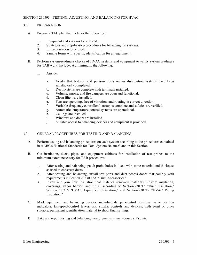
SECTION 230593 - TESTING, ADJUSTING, AND BALANCING FOR HVAC
Ethos Engineering 230593 - 5
3.2 PREPARATION
A. Prepare a TAB plan that includes the following:
1. Equipment and systems to be tested. 2. Strategies and step-by-step procedures for balancing the systems. 3. Instrumentation to be used. 4. Sample forms with specific identification for all equipment.
B. Perform system-readiness checks of HVAC systems and equipment to verify system readiness for TAB work. Include, at a minimum, the following:
1. Airside:
a. Verify that leakage and pressure tests on air distribution systems have been satisfactorily completed.
b. Duct systems are complete with terminals installed. c. Volume, smoke, and fire dampers are open and functional. d. Clean filters are installed. e. Fans are operating, free of vibration, and rotating in correct direction. f. Variable-frequency controllers' startup is complete and safeties are verified. g. Automatic temperature-control systems are operational. h. Ceilings are installed. i. Windows and doors are installed. j. Suitable access to balancing devices and equipment is provided.
3.3 GENERAL PROCEDURES FOR TESTING AND BALANCING
A. Perform testing and balancing procedures on each system according to the procedures contained in AABC's "National Standards for Total System Balance" and in this Section.
B. Cut insulation, ducts, pipes, and equipment cabinets for installation of test probes to the minimum extent necessary for TAB procedures.
1. After testing and balancing, patch probe holes in ducts with same material and thickness as used to construct ducts.
2. After testing and balancing, install test ports and duct access doors that comply with requirements in Section 233300 "Air Duct Accessories."
3. Install and join new insulation that matches removed materials. Restore insulation, coverings, vapor barrier, and finish according to Section 230713 "Duct Insulation," Section 230716 "HVAC Equipment Insulation," and Section 230719 "HVAC Piping Insulation."
C. Mark equipment and balancing devices, including damper-control positions, valve position indicators, fan-speed-control levers, and similar controls and devices, with paint or other suitable, permanent identification material to show final settings.
D. Take and report testing and balancing measurements in inch-pound (IP) units.
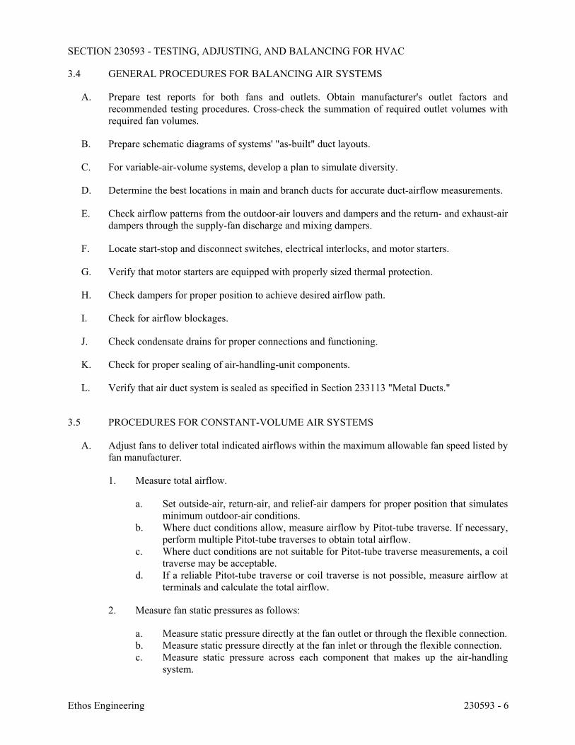
SECTION 230593 - TESTING, ADJUSTING, AND BALANCING FOR HVAC
Ethos Engineering 230593 - 6
3.4 GENERAL PROCEDURES FOR BALANCING AIR SYSTEMS
A. Prepare test reports for both fans and outlets. Obtain manufacturer's outlet factors and recommended testing procedures. Cross-check the summation of required outlet volumes with required fan volumes.
B. Prepare schematic diagrams of systems' "as-built" duct layouts.
C. For variable-air-volume systems, develop a plan to simulate diversity.
D. Determine the best locations in main and branch ducts for accurate duct-airflow measurements.
E. Check airflow patterns from the outdoor-air louvers and dampers and the return- and exhaust-air dampers through the supply-fan discharge and mixing dampers.
F. Locate start-stop and disconnect switches, electrical interlocks, and motor starters.
G. Verify that motor starters are equipped with properly sized thermal protection.
H. Check dampers for proper position to achieve desired airflow path.
I. Check for airflow blockages.
J. Check condensate drains for proper connections and functioning.
K. Check for proper sealing of air-handling-unit components.
L. Verify that air duct system is sealed as specified in Section 233113 "Metal Ducts."
3.5 PROCEDURES FOR CONSTANT-VOLUME AIR SYSTEMS
A. Adjust fans to deliver total indicated airflows within the maximum allowable fan speed listed by fan manufacturer.
1. Measure total airflow.
a. Set outside-air, return-air, and relief-air dampers for proper position that simulates minimum outdoor-air conditions.
b. Where duct conditions allow, measure airflow by Pitot-tube traverse. If necessary, perform multiple Pitot-tube traverses to obtain total airflow.
c. Where duct conditions are not suitable for Pitot-tube traverse measurements, a coil traverse may be acceptable.
d. If a reliable Pitot-tube traverse or coil traverse is not possible, measure airflow at terminals and calculate the total airflow.
2. Measure fan static pressures as follows:
a. Measure static pressure directly at the fan outlet or through the flexible connection. b. Measure static pressure directly at the fan inlet or through the flexible connection. c. Measure static pressure across each component that makes up the air-handling
system.
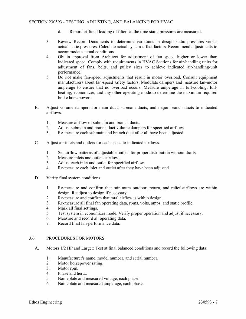
SECTION 230593 - TESTING, ADJUSTING, AND BALANCING FOR HVAC
Ethos Engineering 230593 - 7
d. Report artificial loading of filters at the time static pressures are measured.
3. Review Record Documents to determine variations in design static pressures versus actual static pressures. Calculate actual system-effect factors. Recommend adjustments to accommodate actual conditions.
4. Obtain approval from Architect for adjustment of fan speed higher or lower than indicated speed. Comply with requirements in HVAC Sections for air-handling units for adjustment of fans, belts, and pulley sizes to achieve indicated air-handling-unit performance.
5. Do not make fan-speed adjustments that result in motor overload. Consult equipment manufacturers about fan-speed safety factors. Modulate dampers and measure fan-motor amperage to ensure that no overload occurs. Measure amperage in full-cooling, full-heating, economizer, and any other operating mode to determine the maximum required brake horsepower.
B. Adjust volume dampers for main duct, submain ducts, and major branch ducts to indicated airflows.
1. Measure airflow of submain and branch ducts. 2. Adjust submain and branch duct volume dampers for specified airflow. 3. Re-measure each submain and branch duct after all have been adjusted.
C. Adjust air inlets and outlets for each space to indicated airflows.
1. Set airflow patterns of adjustable outlets for proper distribution without drafts. 2. Measure inlets and outlets airflow. 3. Adjust each inlet and outlet for specified airflow. 4. Re-measure each inlet and outlet after they have been adjusted.
D. Verify final system conditions.
1. Re-measure and confirm that minimum outdoor, return, and relief airflows are within design. Readjust to design if necessary.
2. Re-measure and confirm that total airflow is within design. 3. Re-measure all final fan operating data, rpms, volts, amps, and static profile. 4. Mark all final settings. 5. Test system in economizer mode. Verify proper operation and adjust if necessary. 6. Measure and record all operating data. 7. Record final fan-performance data.
3.6 PROCEDURES FOR MOTORS
A. Motors 1/2 HP and Larger: Test at final balanced conditions and record the following data:
1. Manufacturer's name, model number, and serial number. 2. Motor horsepower rating. 3. Motor rpm. 4. Phase and hertz. 5. Nameplate and measured voltage, each phase. 6. Nameplate and measured amperage, each phase.
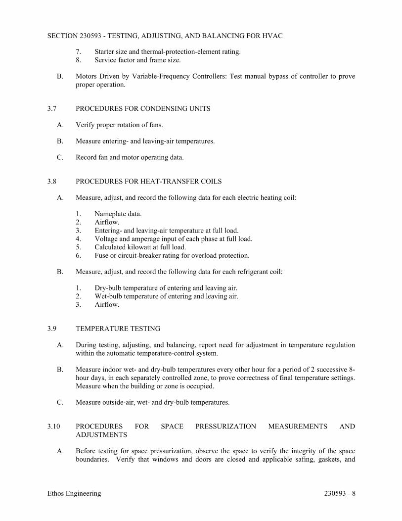
SECTION 230593 - TESTING, ADJUSTING, AND BALANCING FOR HVAC
Ethos Engineering 230593 - 8
7. Starter size and thermal-protection-element rating. 8. Service factor and frame size.
B. Motors Driven by Variable-Frequency Controllers: Test manual bypass of controller to prove proper operation.
3.7 PROCEDURES FOR CONDENSING UNITS
A. Verify proper rotation of fans.
B. Measure entering- and leaving-air temperatures.
C. Record fan and motor operating data.
3.8 PROCEDURES FOR HEAT-TRANSFER COILS
A. Measure, adjust, and record the following data for each electric heating coil:
1. Nameplate data. 2. Airflow. 3. Entering- and leaving-air temperature at full load. 4. Voltage and amperage input of each phase at full load. 5. Calculated kilowatt at full load. 6. Fuse or circuit-breaker rating for overload protection.
B. Measure, adjust, and record the following data for each refrigerant coil:
1. Dry-bulb temperature of entering and leaving air. 2. Wet-bulb temperature of entering and leaving air. 3. Airflow.
3.9 TEMPERATURE TESTING
A. During testing, adjusting, and balancing, report need for adjustment in temperature regulation within the automatic temperature-control system.
B. Measure indoor wet- and dry-bulb temperatures every other hour for a period of 2 successive 8-hour days, in each separately controlled zone, to prove correctness of final temperature settings. Measure when the building or zone is occupied.
C. Measure outside-air, wet- and dry-bulb temperatures.
3.10 PROCEDURES FOR SPACE PRESSURIZATION MEASUREMENTS AND ADJUSTMENTS
A. Before testing for space pressurization, observe the space to verify the integrity of the space boundaries. Verify that windows and doors are closed and applicable safing, gaskets, and
SECTION 230593 - TESTING, ADJUSTING, AND BALANCING FOR HVAC
Ethos Engineering 230593 - 9
sealants are installed. Report deficiencies and postpone testing until after the reported deficiencies are corrected.
B. Measure, adjust, and record the pressurization of each room, each zone, and each building by adjusting the supply, return, and exhaust airflows to achieve the indicated conditions.
C. Measure space pressure differential where pressure is used as the design criteria, and measure airflow differential where differential airflow is used as the design criteria for space pressurization. 1. For pressure measurements, measure and record the pressure difference between the
intended spaces at the door with all doors in the space closed. Record the high-pressure side, low-pressure side, and pressure difference between each adjacent space.
2. For applications with cascading levels of space pressurization, begin in the most critical space and work to the least critical space.
3. Test room pressurization first, then zones, and finish with building pressurization.
D. To achieve indicated pressurization, set the supply airflow to the indicated conditions and adjust the exhaust and return airflow to achieve the indicated pressure or airflow difference.
E. For spaces with pressurization being monitored and controlled automatically, observe and adjust the controls to achieve the desired set point. 1. Compare the values of the measurements taken to the measured values of the control
system instruments and report findings. 2. Check the repeatability of the controls by successive tests designed to temporarily alter
the ability to achieve space pressurization. Test overpressurization and underpressurization, and observe and report on the system's ability to revert to the set point.
3. For spaces served by variable-air-volume supply and exhaust systems, measure space pressurization at indicated airflow and minimum airflow conditions.
F. In spaces that employ multiple modes of operation, such as normal mode and emergency mode or occupied mode and unoccupied mode, measure, adjust, and record data for each operating mode.
G. Record indicated conditions and corresponding initial and final measurements. Report deficiencies.
3.11 PROCEDURES FOR INDOOR-AIR QUALITY MEASUREMENTS
A. After air balancing is complete and with HVAC systems operating at indicated conditions, perform indoor-air quality testing.
B. Observe and record the following conditions for each HVAC system: 1. The distance between the outside-air intake and the closest exhaust fan discharge, flue
termination, or vent termination. 2. Specified filters are installed. Check for leakage around filters. 3. Cooling coil drain pans have a positive slope to drain. 4. Cooling coil condensate drain trap maintains an air seal. 5. Evidence of water damage. 6. Insulation in contact with the supply, return, and outside air is dry and clean.
SECTION 230593 - TESTING, ADJUSTING, AND BALANCING FOR HVAC
Ethos Engineering 230593 - 10
C. Measure and record indoor conditions served by each HVAC system. Make measurements at multiple locations served by the system if required to satisfy the following: 1. Most remote area. 2. One location per floor. 3. One location for every 5000 sq. ft..
D. Measure and record the following indoor conditions for each location two times at two-hour intervals, and in accordance with ASHRAE 113: 1. Temperature. 2. Relative humidity. 3. Air velocity. 4. Concentration of carbon dioxide (ppm).
3.12 DUCT LEAKAGE TESTS
A. Witness the duct pressure testing performed by Installer.
B. Verify that proper test methods are used and that leakage rates are within specified tolerances.
C. Report deficiencies observed.
3.13 CONTROLS VERIFICATION
A. In conjunction with system balancing, perform the following:
1. Verify temperature control system is operating within the design limitations. 2. Confirm that the sequences of operation are in compliance with Contract Documents. 3. Verify that controllers are calibrated and function as intended. 4. Verify that controller set points are as indicated. 5. Verify the operation of lockout or interlock systems. 6. Verify the operation of valve and damper actuators. 7. Verify that controlled devices are properly installed and connected to correct controller. 8. Verify that controlled devices travel freely and are in position indicated by controller:
open, closed, or modulating. 9. Verify location and installation of sensors to ensure that they sense only intended
temperature, humidity, or pressure. 10. Verify controls sequences for other MEP items as specified.
B. Reporting: Include a summary of verifications performed, remaining deficiencies, and variations from indicated conditions.
3.14 TOLERANCES
A. Set HVAC system's airflow rates and water flow rates within the following tolerances:
1. Supply, Return, and Exhaust Fans and Equipment with Fans: Plus or minus 10 percent. 2. Air Outlets and Inlets: Plus or minus 10 percent.
SECTION 230593 - TESTING, ADJUSTING, AND BALANCING FOR HVAC
Ethos Engineering 230593 - 11
B. Maintaining pressure relationships as designed shall have priority over the tolerances specified above.
3.15 PROGRESS REPORTING
A. Initial Construction-Phase Report: Based on examination of the Contract Documents as specified in "Examination" Article, prepare a report on the adequacy of design for systems balancing devices. Recommend changes and additions to systems balancing devices to facilitate proper performance measuring and balancing. Recommend changes and additions to HVAC systems and general construction to allow access for performance measuring and balancing devices.
B. Status Reports: Prepare progress reports to describe completed procedures, procedures in progress, and scheduled procedures. Include a list of deficiencies and problems found in systems being tested and balanced. Prepare a separate report for each system and each building floor for systems serving multiple floors.
3.16 FINAL REPORT
A. General: Prepare a certified written report; tabulate and divide the report into separate sections for tested systems and balanced systems.
1. Include a certification sheet at the front of the report's binder, signed and sealed by the certified testing and balancing engineer.
2. Include a list of instruments used for procedures, along with proof of calibration. 3. Certify validity and accuracy of field data.
B. Final Report Contents: In addition to certified field-report data, include the following:
1. Pump curves. 2. Fan curves. 3. Manufacturers' test data. 4. Field test reports prepared by system and equipment installers. 5. Other information relative to equipment performance; do not include Shop Drawings and
Product Data.
C. General Report Data: In addition to form titles and entries, include the following data:
1. Title page. 2. Name and address of the TAB specialist. 3. Project name. 4. Project location. 5. Architect's name and address. 6. Engineer's name and address. 7. Contractor's name and address. 8. Report date. 9. Signature of TAB supervisor who certifies the report. 10. Table of Contents with the total number of pages defined for each section of the report.
Number each page in the report.
SECTION 230593 - TESTING, ADJUSTING, AND BALANCING FOR HVAC
Ethos Engineering 230593 - 12
11. Summary of contents including the following:
a. Indicated versus final performance. b. Notable characteristics of systems. c. Description of system operation sequence if it varies from the Contract
Documents.
12. Nomenclature sheets for each item of equipment. 13. Data for terminal units, including manufacturer's name, type, size, and fittings. 14. Notes to explain why certain final data in the body of reports vary from indicated values. 15. Test conditions for fans and pump performance forms including the following:
a. Settings for outdoor-, return-, and exhaust-air dampers. b. Conditions of filters. c. Cooling coil, wet- and dry-bulb conditions. d. Face and bypass damper settings at coils. e. Fan drive settings including settings and percentage of maximum pitch diameter. f. Inlet vane settings for variable-air-volume systems. g. Settings for supply-air, static-pressure controller. h. Other system operating conditions that affect performance.
D. System Diagrams: Include schematic layouts of air and hydronic distribution systems. Present each system with single-line diagram and include the following:
1. Quantities of outdoor, supply, return, and exhaust airflows. 2. Duct, outlet, and inlet sizes. 3. Pipe and valve sizes and locations. 4. Terminal units. 5. Balancing stations. 6. Position of balancing devices.
E. Air-Handling-Unit Test Reports: For air-handling units with coils, include the following:
1. Unit Data:
a. Unit identification. b. Location. c. Make and type. d. Model number and unit size. e. Manufacturer's serial number. f. Unit arrangement and class. g. Discharge arrangement. h. Sheave make, size in inches, and bore. i. Center-to-center dimensions of sheave and amount of adjustments in inches. j. Number, make, and size of belts. k. Number, type, and size of filters.
2. Motor Data:
a. Motor make, and frame type and size. b. Horsepower and rpm.
SECTION 230593 - TESTING, ADJUSTING, AND BALANCING FOR HVAC
Ethos Engineering 230593 - 13
c. Volts, phase, and hertz. d. Full-load amperage and service factor. e. Sheave make, size in inches, and bore. f. Center-to-center dimensions of sheave and amount of adjustments in inches.
3. Test Data (Indicated and Actual Values):
a. Total airflow rate in cfm. b. Total system static pressure in inches wg. c. Fan rpm. d. Discharge static pressure in inches wg. e. Filter static-pressure differential in inches wg. f. Cooling-coil static-pressure differential in inches wg. g. Heating-coil static-pressure differential in inches wg. h. Outdoor airflow in cfm. i. Return airflow in cfm. j. Outdoor-air damper position. k. Return-air damper position. l. Vortex damper position.
F. Apparatus-Coil Test Reports:
1. Coil Data:
a. System identification. b. Location. c. Coil type. d. Number of rows. e. Fin spacing in fins per inch o.c. f. Make and model number. g. Face area in sq. ft.. h. Tube size in NPS. i. Tube and fin materials. j. Circuiting arrangement.
2. Test Data (Indicated and Actual Values):
a. Airflow rate in cfm. b. Average face velocity in fpm. c. Air pressure drop in inches wg. d. Outdoor-air, wet- and dry-bulb temperatures in deg F. e. Return-air, wet- and dry-bulb temperatures in deg F. f. Entering-air, wet- and dry-bulb temperatures in deg F. g. Leaving-air, wet- and dry-bulb temperatures in deg F.
G. Electric-Coil Test Reports: For electric furnaces, duct coils, and electric coils installed in central-station air-handling units, include the following:
1. Unit Data:
a. System identification.
SECTION 230593 - TESTING, ADJUSTING, AND BALANCING FOR HVAC
Ethos Engineering 230593 - 14
b. Location. c. Coil identification. d. Capacity in Btu/h. e. Number of stages. f. Connected volts, phase, and hertz. g. Rated amperage. h. Airflow rate in cfm. i. Face area in sq. ft.. j. Minimum face velocity in fpm.
2. Test Data (Indicated and Actual Values):
a. Heat output in Btu/h. b. Airflow rate in cfm. c. Air velocity in fpm. d. Entering-air temperature in deg F. e. Leaving-air temperature in deg F. f. Voltage at each connection. g. Amperage for each phase.
H. Fan Test Reports: For supply, return, and exhaust fans, include the following:
1. Fan Data:
a. System identification. b. Location. c. Make and type. d. Model number and size. e. Manufacturer's serial number. f. Arrangement and class. g. Sheave make, size in inches, and bore. h. Center-to-center dimensions of sheave and amount of adjustments in inches.
2. Motor Data:
a. Motor make, and frame type and size. b. Horsepower and rpm. c. Volts, phase, and hertz. d. Full-load amperage and service factor. e. Sheave make, size in inches, and bore. f. Center-to-center dimensions of sheave, and amount of adjustments in inches. g. Number, make, and size of belts.
3. Test Data (Indicated and Actual Values):
a. Total airflow rate in cfm. b. Total system static pressure in inches wg. c. Fan rpm. d. Discharge static pressure in inches wg. e. Suction static pressure in inches wg.
SECTION 230593 - TESTING, ADJUSTING, AND BALANCING FOR HVAC
Ethos Engineering 230593 - 15
I. Round, Flat-Oval, and Rectangular Duct Traverse Reports: Include a diagram with a grid representing the duct cross-section and record the following:
1. Report Data:
a. System and air-handling-unit number. b. Location and zone. c. Traverse air temperature in deg F. d. Duct static pressure in inches wg. e. Duct size in inches. f. Duct area in sq. ft.. g. Indicated airflow rate in cfm. h. Indicated velocity in fpm. i. Actual airflow rate in cfm. j. Actual average velocity in fpm. k. Barometric pressure in psig.
A. Compressor and Condenser Reports: For refrigerant side of unitary systems, stand-alone refrigerant compressors, air-cooled condensing units, or water-cooled condensing units, include the following:
1. Unit Data: Include the following:
a. Unit identification. b. Location. c. Unit make and model number. d. Manufacturer's compressor model and serial numbers. e. Refrigerant weight in lb. f. Low ambient temperature cutoff in deg F.
2. Test Data: Include design and actual values for the following:
a. Inlet-duct static pressure in inches wg. b. Outlet-duct static pressure in inches wg. c. Entering-air, dry-bulb temperature in deg F. d. Leaving-air, dry-bulb temperature in deg F. e. Control settings. f. Unloader set points. g. Low-pressure-cutout set point in psig. h. High-pressure-cutout set point in psig. i. Suction pressure in psig. j. Suction temperature in deg F. k. Condenser refrigerant pressure in psig. l. Condenser refrigerant temperature in deg F. m. Oil pressure in psig. n. Oil temperature in deg F. o. Voltage at each connection. p. Amperage for each phase. q. The kW input. r. Crankcase heater kW. s. Number of fans.
SECTION 230593 - TESTING, ADJUSTING, AND BALANCING FOR HVAC
Ethos Engineering 230593 - 16
t. Condenser fan rpm. u. Condenser fan airflow rate in cfm. v. Condenser fan motor make, frame size, rpm, and horsepower. w. Condenser fan motor voltage at each connection. x. Condenser fan motor amperage for each phase.
B. Indoor-Air Quality Measurement Reports for Each HVAC System: 1. HVAC system designation. 2. Date and time of test. 3. Outdoor temperature, relative humidity, wind speed, and wind direction at start of test. 4. Room number or similar description for each location. 5. Measurements at each location. 6. Observed deficiencies.
C. Instrument Calibration Reports:
1. Report Data:
a. Instrument type and make. b. Serial number. c. Application. d. Dates of use. e. Dates of calibration.
3.17 VERIFICATION OF TAB REPORT
A. Architect shall randomly select measurements, documented in the final report, to be rechecked. Rechecking shall be limited to either 10 percent of the total measurements recorded or the extent of measurements that can be accomplished in a normal 8-hour business day.
B. If rechecks yield measurements that differ from the measurements documented in the final report by more than the tolerances allowed, the measurements shall be noted as "FAILED."
C. If the number of "FAILED" measurements is greater than 10 percent of the total measurements checked during the final inspection, the testing and balancing shall be considered incomplete and shall be rejected.
D. If TAB work fails, proceed as follows:
1. TAB specialists shall recheck all measurements and make adjustments. Revise the final report and balancing device settings to include all changes; resubmit the final report and request a second final inspection.
2. If the second final inspection also fails, Owner may contract the services of another TAB specialist to complete TAB work according to the Contract Documents and deduct the cost of the services from the original TAB specialist's final payment.
3. If the second verification also fails, Architect may contact AABC Headquarters regarding the AABC National Performance Guaranty.
E. Prepare test and inspection reports.
SECTION 230593 - TESTING, ADJUSTING, AND BALANCING FOR HVAC
Ethos Engineering 230593 - 17
3.18 ADDITIONAL TESTS
A. Within 90 days of completing TAB, perform additional TAB to verify that balanced conditions are being maintained throughout and to correct unusual conditions.
B. Seasonal Periods: If initial TAB procedures were not performed during near-peak summer and winter conditions, perform additional TAB during near-peak summer and winter conditions.
END OF SECTION 230593
SECTION 230713 - DUCT INSULATION
Ethos Engineering 230713 - 1
PART 1 - GENERAL
1.1 RELATED DOCUMENTS
A. Drawings and general provisions of the Contract, including General and Supplementary Conditions and Division 01 Specification Sections, apply to this Section.
1.2 SUMMARY
A. Section includes insulating the following duct services:
1. Indoor, concealed supply and outdoor air. 2. Indoor, concealed return located in unconditioned space.
B. Related Sections: 1. Section 230719 "HVAC Piping Insulation." 2. Section 233113 "Metal Ducts" for duct liners.
1.3 ACTION SUBMITTALS
A. Product Data: For each type of product indicated. Include thermal conductivity, water-vapor permeance thickness, and jackets (both factory- and field-applied if any).
B. Shop Drawings: Include plans, elevations, sections, details, and attachments to other work.
1. Detail application of protective shields, saddles, and inserts at hangers for each type of insulation and hanger.
2. Detail insulation application at elbows, fittings, dampers, specialties and flanges for each type of insulation.
3. Detail application of field-applied jackets. 4. Detail application at linkages of control devices.
1.4 INFORMATIONAL SUBMITTALS
A. Qualification Data: For qualified Installer.
B. Field quality-control reports.
1.5 QUALITY ASSURANCE
A. Surface-Burning Characteristics: For insulation and related materials, as determined by testing identical products according to ASTM E 84, by a testing agency acceptable to authorities having jurisdiction. Factory label insulation and jacket materials and adhesive, mastic, tapes, and cement material containers, with appropriate markings of applicable testing agency.
SECTION 230713 - DUCT INSULATION
Ethos Engineering 230713 - 2
1. Insulation Installed Indoors: Flame-spread index of 25 or less, and smoke-developed index of 50 or less.
2. Insulation Installed Outdoors: Flame-spread index of 75 or less, and smoke-developed index of 150 or less.
1.6 DELIVERY, STORAGE, AND HANDLING
A. Packaging: Insulation material containers shall be marked by manufacturer with appropriate ASTM standard designation, type and grade, and maximum use temperature.
1.7 COORDINATION
A. Coordinate sizes and locations of supports, hangers, and insulation shields specified in Section 230529 "Hangers and Supports for HVAC Piping and Equipment."
B. Coordinate clearance requirements with duct Installer for duct insulation application. Before preparing ductwork Shop Drawings, establish and maintain clearance requirements for installation of insulation and field-applied jackets and finishes and for space required for maintenance.
C. Coordinate installation and testing of heat tracing.
1.8 SCHEDULING
A. Schedule insulation application after pressure testing systems and, where required, after installing and testing heat tracing. Insulation application may begin on segments that have satisfactory test results.
PART 2 - PRODUCTS
2.1 MANUFACTURERS
A. Manufacturers: Subject to compliance with requirements, manufacturers offering products that may be incorporated into the Work include, and are limited to, the following: 1. Mineral-Fiber Insulation:
a. CertainTeed b. Manson. c. Knauf FiberGlass GmbH. d. Owens-Corning Fiberglas Corp. e. Schuller International, Inc.
2.2 INSULATION MATERIALS
A. Comply with requirements in "Duct Insulation Schedule, General," "Indoor Duct and Plenum Insulation Schedule," and "Aboveground, Outdoor Duct and Plenum Insulation Schedule" articles for where insulating materials shall be applied.
SECTION 230713 - DUCT INSULATION
Ethos Engineering 230713 - 3
B. Products shall not contain asbestos, lead, mercury, or mercury compounds.
C. Products that come in contact with stainless steel shall have a leachable chloride content of less than 50 ppm when tested according to ASTM C 871.
D. Insulation materials for use on austenitic stainless steel shall be qualified as acceptable according to ASTM C 795.
E. Foam insulation materials shall not use CFC or HCFC blowing agents in the manufacturing process.
F. Flexible Elastomeric Insulation: Closed-cell, sponge- or expanded-rubber materials. Comply with ASTM C 534, Type II for sheet materials.
G. Mineral-Fiber Blanket Insulation: Mineral or glass fibers bonded with a thermosetting resin. Comply with ASTM C 553, Type II and ASTM C 1290. Factory-applied jacket requirements are specified in "Factory-Applied Jackets" Article.
2.3 ADHESIVES
A. Materials shall be compatible with insulation materials, jackets, and substrates and for bonding insulation to itself and to surfaces to be insulated unless otherwise indicated.
B. Mineral-Fiber Adhesive: Comply with MIL-A-3316C, Class 2, Grade A.
1. For indoor applications, adhesive shall have a VOC content of 80 g/L or less when calculated according to 40 CFR 59, Subpart D (EPA Method 24).
2. Adhesive shall comply with the testing and product requirements of the California Department of Health Services' "Standard Practice for the Testing of Volatile Organic Emissions from Various Sources Using Small-Scale Environmental Chambers."
C. ASJ Adhesive, and FSK Jacket Adhesive: Comply with MIL-A-3316C, Class 2, Grade A for bonding insulation jacket lap seams and joints.
1. For indoor applications, adhesive shall have a VOC content of 50 g/L or less when calculated according to 40 CFR 59, Subpart D (EPA Method 24).
2. Adhesive shall comply with the testing and product requirements of the California Department of Health Services' "Standard Practice for the Testing of Volatile Organic Emissions from Various Sources Using Small-Scale Environmental Chambers."
2.4 MASTICS
A. Materials shall be compatible with insulation materials, jackets, and substrates; comply with MIL-PRF-19565C, Type II.
1. For indoor applications, use mastics that have a VOC content of 50 g/L or less when calculated according to 40 CFR 59, Subpart D (EPA Method 24).
SECTION 230713 - DUCT INSULATION
Ethos Engineering 230713 - 4
2.5 LAGGING ADHESIVES
A. Description: Comply with MIL-A-3316C, Class I, Grade A and shall be compatible with insulation materials, jackets, and substrates.
1. For indoor applications, use lagging adhesives that have a VOC content of 50 g/L or less when calculated according to 40 CFR 59, Subpart D (EPA Method 24).
2. Fire-resistant, water-based lagging adhesive and coating for use indoors to adhere fire-resistant lagging cloths over duct insulation.
3. Service Temperature Range: 0 to plus 180 deg F. 4. Color: White.
2.6 SEALANTS
A. FSK and Metal Jacket Flashing Sealants: 1. Materials shall be compatible with insulation materials, jackets, and substrates. 2. Fire- and water-resistant, flexible, elastomeric sealant. 3. Service Temperature Range: Minus 40 to plus 250 deg F. 4. Color: Aluminum. 5. For indoor applications, sealants shall have a VOC content of 420 g/L or less when
calculated according to 40 CFR 59, Subpart D (EPA Method 24). 6. Sealants shall comply with the testing and product requirements of the California
Department of Health Services' "Standard Practice for the Testing of Volatile Organic Emissions from Various Sources Using Small-Scale Environmental Chambers."
2.7 FACTORY-APPLIED JACKETS
A. Insulation system schedules indicate factory-applied jackets on various applications. When factory-applied jackets are indicated, comply with the following: 1. FSK Jacket: Aluminum-foil, fiberglass-reinforced scrim with kraft-paper backing;
complying with ASTM C 1136, Type II.
2.8 FIELD-APPLIED JACKETS
A. Field-applied jackets shall comply with ASTM C 921, Type I, unless otherwise indicated.
B. FSK Jacket: Aluminum-foil-face, fiberglass-reinforced scrim with kraft-paper backing.
2.9 TAPES
A. FSK Tape: Foil-face, vapor-retarder tape matching factory-applied jacket with acrylic adhesive; complying with ASTM C 1136. 1. Width: 4 inches. 2. Thickness: 6.5 mils. 3. Adhesion: 90 ounces force/inch in width. 4. Elongation: 2 percent. 5. Tensile Strength: 40 lbf/inch in width.
SECTION 230713 - DUCT INSULATION
Ethos Engineering 230713 - 5
6. FSK Tape Disks and Squares: Precut disks or squares of FSK tape.
2.10 SECUREMENTS
A. Bands:
1. Stainless Steel: ASTM A 167 or ASTM A 240/A 240M, Type 304 or Type 316; 0.015 inch thick, 3/4 inch wide.
B. Insulation Pins and Hangers:
1. Capacitor-Discharge-Weld Pins: Copper- or zinc-coated steel pin, fully annealed for capacitor-discharge welding, 0.135-inch- diameter shank, length to suit depth of insulation indicated.
2. Insulation-Retaining Washers: Self-locking washers formed from 0.016-inch-thick, galvanized-steel sheet, with beveled edge sized as required to hold insulation securely in place but not less than 1-1/2 inches in diameter. a. Protect ends with capped self-locking washers incorporating a spring steel insert to
ensure permanent retention of cap in exposed locations.
C. Staples: Outward-clinching insulation staples, nominal 3/4-inch-wide, stainless steel or Monel.
D. Wire: 0.062-inch soft-annealed, stainless steel.
PART 3 - EXECUTION
3.1 EXAMINATION
A. Examine substrates and conditions for compliance with requirements for installation tolerances and other conditions affecting performance of insulation application.
1. Verify that systems to be insulated have been tested and are free of defects. 2. Verify that surfaces to be insulated are clean and dry.
B. Proceed with installation only after unsatisfactory conditions have been corrected.
3.2 PREPARATION
A. Surface Preparation: Clean and dry surfaces to receive insulation. Remove materials that will adversely affect insulation application.
3.3 GENERAL INSTALLATION REQUIREMENTS
A. Install insulation materials, accessories, and finishes with smooth, straight, and even surfaces; free of voids throughout the length of ducts and fittings.
SECTION 230713 - DUCT INSULATION
Ethos Engineering 230713 - 6
B. Install insulation materials, vapor barriers or retarders, jackets, and thicknesses required for each item of duct system as specified in insulation system schedules.
C. Install accessories compatible with insulation materials and suitable for the service. Install accessories that do not corrode, soften, or otherwise attack insulation or jacket in either wet or dry state.
D. Install insulation with longitudinal seams at top and bottom of horizontal runs.
E. Install multiple layers of insulation with longitudinal and end seams staggered.
F. Keep insulation materials dry during application and finishing.
G. Install insulation with tight longitudinal seams and end joints. Bond seams and joints with adhesive recommended by insulation material manufacturer.
H. Install insulation with least number of joints practical.
I. Where vapor barrier is indicated, seal joints, seams, and penetrations in insulation at hangers, supports, anchors, and other projections with vapor-barrier mastic.
1. Install insulation continuously through hangers and around anchor attachments. 2. For insulation application where vapor barriers are indicated, extend insulation on anchor
legs from point of attachment to supported item to point of attachment to structure. Taper and seal ends at attachment to structure with vapor-barrier mastic.
3. Install insert materials and install insulation to tightly join the insert. Seal insulation to insulation inserts with adhesive or sealing compound recommended by insulation material manufacturer.
J. Apply adhesives, mastics, and sealants at manufacturer's recommended coverage rate and wet and dry film thicknesses.
K. Install insulation with factory-applied jackets as follows:
1. Draw jacket tight and smooth. 2. Cover circumferential joints with 3-inch-wide strips, of same material as insulation
jacket. Secure strips with adhesive and outward clinching staples along both edges of strip, spaced 4 inches o.c.
3. Overlap jacket longitudinal seams at least 1-1/2 inches. Clean and dry surface to receive self-sealing lap. Staple laps with outward clinching staples along edge at 2 inches o.c.
a. For below ambient services, apply vapor-barrier mastic over staples.
4. Cover joints and seams with tape, according to insulation material manufacturer's written instructions, to maintain vapor seal.
5. Where vapor barriers are indicated, apply vapor-barrier mastic on seams and joints and at ends adjacent to duct flanges and fittings.
L. Cut insulation in a manner to avoid compressing insulation more than 75 percent of its nominal thickness.
SECTION 230713 - DUCT INSULATION
Ethos Engineering 230713 - 7
M. Finish installation with systems at operating conditions. Repair joint separations and cracking due to thermal movement.
N. Repair damaged insulation facings by applying same facing material over damaged areas. Extend patches at least 4 inches beyond damaged areas. Adhere, staple, and seal patches similar to butt joints.
3.4 PENETRATIONS
A. Insulation Installation at Roof Penetrations: Install insulation continuously through roof penetrations.
1. Seal penetrations with flashing sealant. 2. For applications requiring only indoor insulation, terminate insulation above roof surface
and seal with joint sealant. For applications requiring indoor and outdoor insulation, install insulation for outdoor applications tightly joined to indoor insulation ends. Seal joint with joint sealant.
3. Extend jacket of outdoor insulation outside roof flashing at least 2 inches below top of roof flashing.
4. Seal jacket to roof flashing with flashing sealant.
B. Insulation Installation at Aboveground Exterior Wall Penetrations: Install insulation continuously through wall penetrations.
1. Seal penetrations with flashing sealant. 2. For applications requiring only indoor insulation, terminate insulation inside wall surface
and seal with joint sealant. For applications requiring indoor and outdoor insulation, install insulation for outdoor applications tightly joined to indoor insulation ends. Seal joint with joint sealant.
3. Extend jacket of outdoor insulation outside wall flashing and overlap wall flashing at least 2 inches.
4. Seal jacket to wall flashing with flashing sealant.
C. Insulation Installation at Interior Wall and Partition Penetrations (That Are Not Fire Rated): Install insulation continuously through walls and partitions.
D. Insulation Installation at Fire-Rated Wall and Partition Penetrations: Terminate insulation at fire damper sleeves for fire-rated wall and partition penetrations. Externally insulate damper sleeves to match adjacent insulation and overlap duct insulation at least 2 inches.
1. Comply with requirements in Section 078413 "Penetration Firestopping" and fire-resistive joint sealers.
E. Insulation Installation at Floor Penetrations:
1. Duct: For penetrations through fire-rated assemblies, terminate insulation at fire damper sleeves and externally insulate damper sleeve beyond floor to match adjacent duct insulation. Overlap damper sleeve and duct insulation at least 2 inches.
2. Seal penetrations through fire-rated assemblies. Comply with requirements in Section 078413 "Penetration Firestopping."
SECTION 230713 - DUCT INSULATION
Ethos Engineering 230713 - 8
3.5 INSTALLATION OF MINERAL-FIBER INSULATION
A. Blanket Insulation Installation on Ducts and Plenums: Secure with adhesive and insulation pins.
1. Apply adhesives according to manufacturer's recommended coverage rates per unit area, for 100 percent coverage of duct and plenum surfaces.
2. Apply adhesive to entire circumference of ducts and to all surfaces of fittings and transitions.
3. Install either capacitor-discharge-weld pins and speed washers or cupped-head, capacitor-discharge-weld pins on sides and bottom of horizontal ducts and sides of vertical ducts as follows:
a. On duct sides with dimensions 18 inches and smaller, place pins along longitudinal centerline of duct. Space 3 inches maximum from insulation end joints, and 16 inches o.c.
b. On duct sides with dimensions larger than 18 inches, place pins 16 inches o.c. each way, and 3 inches maximum from insulation joints. Install additional pins to hold insulation tightly against surface at cross bracing.
c. Pins may be omitted from top surface of horizontal, rectangular ducts and plenums. d. Do not overcompress insulation during installation. e. Impale insulation over pins and attach speed washers. f. Cut excess portion of pins extending beyond speed washers or bend parallel with
insulation surface. Cover exposed pins and washers with tape matching insulation facing.
4. For ducts and plenums with surface temperatures below ambient, install a continuous unbroken vapor barrier. Create a facing lap for longitudinal seams and end joints with insulation by removing 2 inches from one edge and one end of insulation segment. Secure laps to adjacent insulation section with 1/2-inch outward-clinching staples, 1 inch o.c. Install vapor barrier consisting of factory- or field-applied jacket, adhesive, vapor-barrier mastic, and sealant at joints, seams, and protrusions.
a. Repair punctures, tears, and penetrations with tape or mastic to maintain vapor-barrier seal.
b. Install vapor stops for ductwork and plenums operating below 50 deg F at 18-foot intervals. Vapor stops shall consist of vapor-barrier mastic applied in a Z-shaped pattern over insulation face, along butt end of insulation, and over the surface. Cover insulation face and surface to be insulated a width equal to two times the insulation thickness, but not less than 3 inches.
5. Overlap unfaced blankets a minimum of 2 inches on longitudinal seams and end joints. At end joints, secure with steel bands spaced a maximum of 18 inches o.c.
6. Install insulation on rectangular duct elbows and transitions with a full insulation section for each surface. Install insulation on round and flat-oval duct elbows with individually mitered gores cut to fit the elbow.
7. Insulate duct stiffeners, hangers, and flanges that protrude beyond insulation surface with 6-inch-wide strips of same material used to insulate duct. Secure on alternating sides of stiffener, hanger, and flange with pins spaced 6 inches o.c.
SECTION 230713 - DUCT INSULATION
Ethos Engineering 230713 - 9
3.6 FIELD-APPLIED JACKET INSTALLATION
A. Where glass-cloth jackets are indicated, install directly over bare insulation or insulation with factory-applied jackets.
1. Draw jacket smooth and tight to surface with 2-inch overlap at seams and joints. 2. Embed glass cloth between two 0.062-inch-thick coats of lagging adhesive. 3. Completely encapsulate insulation with coating, leaving no exposed insulation.
B. Where FSK jackets are indicated, install as follows:
1. Draw jacket material smooth and tight. 2. Install lap or joint strips with same material as jacket. 3. Secure jacket to insulation with manufacturer's recommended adhesive. 4. Install jacket with 1-1/2-inch laps at longitudinal seams and 3-inch-wide joint strips at
end joints. 5. Seal openings, punctures, and breaks in vapor-retarder jackets and exposed insulation
with vapor-barrier mastic.
C. Where PVC jackets are indicated, install with 1-inch overlap at longitudinal seams and end joints; for horizontal applications, install with longitudinal seams along top and bottom of tanks and vessels. Seal with manufacturer's recommended adhesive.
1. Apply two continuous beads of adhesive to seams and joints, one bead under lap and the finish bead along seam and joint edge.
D. Where metal jackets are indicated, install with 2-inch overlap at longitudinal seams and end joints. Overlap longitudinal seams arranged to shed water. Seal end joints with weatherproof sealant recommended by insulation manufacturer. Secure jacket with stainless-steel bands 12 inches o.c. and at end joints.
3.7 FINISHES
A. Insulation with ASJ, Glass-Cloth, or Other Paintable Jacket Material: Paint jacket with paint system identified below and as specified in Division 9.
1. Flat Acrylic Finish: Two finish coats over a primer that is compatible with jacket material and finish coat paint. Add fungicidal agent to render fabric mildew proof.
a. Finish Coat Material: Interior, flat, latex-emulsion size.
B. Color: Final color as selected by Architect. Vary first and second coats to allow visual inspection of the completed Work.
C. Do not field paint aluminum or stainless-steel jackets.
3.8 FIELD QUALITY CONTROL
A. Perform tests and inspections.
SECTION 230713 - DUCT INSULATION
Ethos Engineering 230713 - 10
B. Tests and Inspections:
1. Inspect ductwork, randomly selected by Architect, by removing field-applied jacket and insulation in layers in reverse order of their installation.
C. All insulation applications will be considered defective Work if sample inspection reveals noncompliance with requirements.
3.9 DUCT INSULATION SCHEDULE, GENERAL
A. Plenums and Ducts Requiring Insulation:
1. Indoor, concealed supply and outdoor air. 2. Indoor, exposed supply and outdoor air. 3. Indoor, concealed return located in unconditioned space. 4. Indoor, exposed return located in unconditioned space. 5. Indoor, concealed exhaust between isolation damper and penetration of building exterior. 6. Indoor, exposed exhaust between isolation damper and penetration of building exterior. 7. Outdoor, concealed supply and return. 8. Outdoor, exposed supply and return.
B. Items Not Insulated:
1. Fibrous-glass ducts. 2. Metal ducts with duct liner of sufficient thickness to comply with energy code and
ASHRAE/IESNA 90.1. 3. Factory-insulated flexible ducts. 4. Factory-insulated plenums and casings. 5. Flexible connectors. 6. Vibration-control devices. 7. Factory-insulated access panels and doors.
3.10 INDOOR DUCT AND PLENUM INSULATION SCHEDULE
A. Service: Round & rectangular, supply-air ducts concealed. 1. Material: Mineral-fiber blanket. 2. Thickness: 3 inches (R-8 min). 3. Number of Layers: One. 4. Field-Applied Jacket: Foil and paper. 5. Vapor Retarder Required: Yes.
B. Service: Round & rectangular, return, outside-air and fume hood exhaust ducts concealed. 1. Material: Mineral-fiber blanket. 2. Thickness: 2 inches (R-6 min). 3. Number of Layers: One. 4. Field-Applied Jacket: Foil and paper. 5. Vapor Retarder Required: Yes.
C. Service: Ten feet of supply and return air ducts closest to AHU or FCU.
SECTION 230713 - DUCT INSULATION
Ethos Engineering 230713 - 11
1. Material: In addition to exterior wrap, provide internal liner for sound attenuation purposes.
2. Thickness: 1 inches.
D. Service: Ten feet of exhaust air duct closest to where duct penetrates the exterior envelope. 1. Material: Exterior wrap. 2. Thickness: 2 inches.
E. Where ductwork is not completely concealed, paint all ductwork and insulation. Coordinate color and finish with Architect.
END OF SECTION 230713
SECTION 230719 - HVAC PIPING INSULATION
Ethos Engineering 230719 - 1
PART 1 - GENERAL
1.1 RELATED DOCUMENTS
A. Drawings and general provisions of the Contract, including General and Supplementary Conditions and Division 01 Specification Sections, apply to this Section.
1.2 SUMMARY
A. Section includes insulating the following HVAC piping systems: 1. Condensate drain piping, indoors. 2. Refrigerant piping, indoors and outdoors.
B. Related Sections: 1. Section 230713 "Duct Insulation."
1.3 ACTION SUBMITTALS
A. Product Data: For each type of product indicated. Include thermal conductivity, water-vapor permeance thickness, and jackets (both factory and field applied if any).
B. Shop Drawings: Include plans, elevations, sections, details, and attachments to other work. 1. Detail application of protective shields, saddles, and inserts at hangers for each type of
insulation and hanger. 2. Detail attachment and covering of heat tracing inside insulation. 3. Detail insulation application at pipe expansion joints for each type of insulation. 4. Detail insulation application at elbows, fittings, flanges, valves, and specialties for each
type of insulation. 5. Detail removable insulation at piping specialties. 6. Detail application of field-applied jackets. 7. Detail application at linkages of control devices.
1.4 QUALITY ASSURANCE
A. Surface-Burning Characteristics: For insulation and related materials, as determined by testing identical products according to ASTM E 84, by a testing and inspecting agency acceptable to authorities having jurisdiction. Factory label insulation and jacket materials and adhesive, mastic, tapes, and cement material containers, with appropriate markings of applicable testing agency. 1. Insulation Installed Indoors: Flame-spread index of 25 or less, and smoke-developed
index of 50 or less. 2. Insulation Installed Outdoors: Flame-spread index of 75 or less, and smoke-developed
index of 150 or less.
SECTION 230719 - HVAC PIPING INSULATION
Ethos Engineering 230719 - 2
1.5 DELIVERY, STORAGE, AND HANDLING
A. Packaging: Insulation material containers shall be marked by manufacturer with appropriate ASTM standard designation, type and grade, and maximum use temperature.
1.6 COORDINATION
A. Coordinate sizes and locations of supports, hangers, and insulation shields specified in Section 230529 "Hangers and Supports for HVAC Piping and Equipment."
B. Coordinate clearance requirements with piping Installer for piping insulation application. Before preparing piping Shop Drawings, establish and maintain clearance requirements for installation of insulation and field-applied jackets and finishes and for space required for maintenance.
C. Coordinate installation and testing of heat tracing.
1.7 SCHEDULING
A. Schedule insulation application after pressure testing systems and, where required, after installing and testing heat tracing. Insulation application may begin on segments that have satisfactory test results.
B. Complete installation and concealment of plastic materials as rapidly as possible in each area of construction.
PART 2 - PRODUCTS
2.1 MANUFACTURERS
A. Manufacturers: Subject to compliance with requirements, manufacturers offering products that may be incorporated into the Work include, but are not limited to, the following:
1. Flexible Elastomeric Thermal Insulation: a. Aeroflex USA Inc.; Aerocel. b. Armacell LLC; AP Armaflex. c. RBX Corporation; Insul-Sheet 1800 and Insul-Tube 180.
2.2 INSULATION MATERIALS
A. Mineral-fiber insulation will NOT be allowed for use on any cold piping systems.
B. Mineral-fiber wrap is NOT approved for use on piping insulation.
C. Comply with requirements in "Piping Insulation Schedule, General," "Indoor Piping Insulation Schedule," "Outdoor, Aboveground Piping Insulation Schedule," and "Outdoor, Underground Piping Insulation Schedule" articles for where insulating materials shall be applied.
SECTION 230719 - HVAC PIPING INSULATION
Ethos Engineering 230719 - 3
D. Products shall not contain asbestos, lead, mercury, or mercury compounds.
E. Products that come in contact with stainless steel shall have a leachable chloride content of less than 50 ppm when tested according to ASTM C 871.
F. Insulation materials for use on austenitic stainless steel shall be qualified as acceptable according to ASTM C 795.
G. Foam insulation materials shall not use CFC or HCFC blowing agents in the manufacturing process.
H. Flexible Elastomeric Insulation: Closed-cell, sponge- or expanded-rubber materials. Comply with ASTM C 534, Type I for tubular materials.
2.3 ADHESIVES
A. Materials shall be compatible with insulation materials, jackets, and substrates and for bonding insulation to itself and to surfaces to be insulated unless otherwise indicated.
B. Flexible Elastomeric and Polyolefin Adhesive: Comply with MIL-A-24179A, Type II, Class I. 1. Products:
a. Aeroflex USA Inc.; Aeroseal. b. Armacell LCC; 520 Adhesive. c. Foster Products Corporation, H. B. Fuller Company; 85-75. d. RBX Corporation; Rubatex Contact Adhesive.
2. For indoor applications, adhesive shall have a VOC content of 50 g/L or less when calculated according to 40 CFR 59, Subpart D (EPA Method 24).
3. Adhesive shall comply with the testing and product requirements of the California Department of Health Services' "Standard Practice for the Testing of Volatile Organic Emissions from Various Sources Using Small-Scale Environmental Chambers."
C. ASJ Adhesive, and FSK and PVDC Jacket Adhesive: Comply with MIL-A-3316C, Class 2, Grade A for bonding insulation jacket lap seams and joints. 1. Products:
a. Childers Products, Division of ITW; CP-82. b. Foster Products Corporation, H. B. Fuller Company; 85-20. c. ITW TACC, Division of Illinois Tool Works; S-90/80. d. Marathon Industries, Inc.; 225. e. Mon-Eco Industries, Inc.; 22-25.
2. For indoor applications, adhesive shall have a VOC content of 50 g/L or less when calculated according to 40 CFR 59, Subpart D (EPA Method 24).
3. Adhesive shall comply with the testing and product requirements of the California Department of Health Services' "Standard Practice for the Testing of Volatile Organic Emissions from Various Sources Using Small-Scale Environmental Chambers."
SECTION 230719 - HVAC PIPING INSULATION
Ethos Engineering 230719 - 4
2.4 MASTICS
A. Materials shall be compatible with insulation materials, jackets, and substrates; comply with MIL-PRF-19565C, Type II. 1. For indoor applications, use mastics that have a VOC content of 50 g/L or less when
calculated according to 40 CFR 59, Subpart D (EPA Method 24).
2.5 LAGGING ADHESIVES
A. Description: Comply with MIL-A-3316C, Class I, Grade A and shall be compatible with insulation materials, jackets, and substrates. 1. For indoor applications, use lagging adhesives that have a VOC content of 50 g/L or less
when calculated according to 40 CFR 59, Subpart D (EPA Method 24). 2. Fire-resistant, water-based lagging adhesive and coating for use indoors to adhere fire-
resistant lagging cloths over pipe insulation. 3. Service Temperature Range: 0 to plus 180 deg F. 4. Color: White.
2.6 SEALANTS
A. Joint Sealants: 1. Materials shall be compatible with insulation materials, jackets, and substrates. 2. Permanently flexible, elastomeric sealant. 3. Service Temperature Range: Minus 100 to plus 300 deg F. 4. Color: White or gray. 5. For indoor applications, sealants shall have a VOC content of 420 g/L or less when
calculated according to 40 CFR 59, Subpart D (EPA Method 24). 6. Sealants shall comply with the testing and product requirements of the California
Department of Health Services' "Standard Practice for the Testing of Volatile Organic Emissions from Various Sources Using Small-Scale Environmental Chambers."
B. FSK and Metal Jacket Flashing Sealants: 1. Materials shall be compatible with insulation materials, jackets, and substrates. 2. Fire- and water-resistant, flexible, elastomeric sealant. 3. Service Temperature Range: Minus 40 to plus 250 deg F. 4. Color: Aluminum. 5. For indoor applications, sealants shall have a VOC content of 420 g/L or less when
calculated according to 40 CFR 59, Subpart D (EPA Method 24). 6. Sealants shall comply with the testing and product requirements of the California
Department of Health Services' "Standard Practice for the Testing of Volatile Organic Emissions from Various Sources Using Small-Scale Environmental Chambers."
C. ASJ Flashing Sealants, Jacket Flashing Sealants: 1. Materials shall be compatible with insulation materials, jackets, and substrates. 2. Fire- and water-resistant, flexible, elastomeric sealant. 3. Service Temperature Range: Minus 40 to plus 250 deg F. 4. Color: White. 5. For indoor applications, sealants shall have a VOC content of 420 g/L or less when
calculated according to 40 CFR 59, Subpart D (EPA Method 24).
SECTION 230719 - HVAC PIPING INSULATION
Ethos Engineering 230719 - 5
6. Sealants shall comply with the testing and product requirements of the California Department of Health Services' "Standard Practice for the Testing of Volatile Organic Emissions from Various Sources Using Small-Scale Environmental Chambers."
2.7 FACTORY-APPLIED JACKETS
A. Insulation system schedules indicate factory-applied jackets on various applications. When factory-applied jackets are indicated, comply with the following: 1. ASJ: White, kraft-paper, fiberglass-reinforced scrim with aluminum-foil backing;
complying with ASTM C 1136, Type I. 2. FSK Jacket: Aluminum-foil, fiberglass-reinforced scrim with kraft-paper backing;
complying with ASTM C 1136, Type II.
2.8 FIELD-APPLIED FABRIC-REINFORCING MESH
A. Woven Glass-Fiber Fabric: Approximately 2 oz./sq. yd. with a thread count of 10 strands by 10 strands/sq. in. for covering pipe and pipe fittings.
2.9 FIELD-APPLIED CLOTHS
A. Woven Glass-Fiber Fabric: Comply with MIL-C-20079H, Type I, plain weave, and presized a minimum of 8 oz./sq. yd..
2.10 FIELD-APPLIED JACKETS
A. Field-applied jackets shall comply with ASTM C 921, Type I, unless otherwise indicated.
B. FSK Jacket: Aluminum-foil-face, fiberglass-reinforced scrim with kraft-paper backing.
C. Metal Jacket: 1. Aluminum Jacket: Comply with ASTM B 209, Alloy 3003, 3005, 3105, or 5005,
Temper H-14. a. Factory cut and rolled to size. b. Finish and thickness are indicated in field-applied jacket schedules. c. Moisture Barrier: 3-mil-thick, heat-bonded polyethylene and kraft paper. d. Factory-Fabricated Fitting Covers:
1) Same material, finish, and thickness as jacket. 2) Preformed 2-piece or gore, 45- and 90-degree, short- and long-radius
elbows. 3) Tee covers. 4) Flange and union covers. 5) End caps. 6) Beveled collars. 7) Valve covers. 8) Field fabricate fitting covers only if factory-fabricated fitting covers are not
available.
SECTION 230719 - HVAC PIPING INSULATION
Ethos Engineering 230719 - 6
D. Underground Direct-Buried Jacket: 125-mil-thick vapor barrier and waterproofing membrane consisting of a rubberized bituminous resin reinforced with a woven-glass fiber or polyester scrim and laminated aluminum foil.
2.11 TAPES
A. ASJ Tape: White vapor-retarder tape matching factory-applied jacket with acrylic adhesive, complying with ASTM C 1136. 1. Width: 3 inches. 2. Thickness: 11.5 mils. 3. Adhesion: 90 ounces force/inch in width. 4. Elongation: 2 percent. 5. Tensile Strength: 40 lbf/inch in width. 6. ASJ Tape Disks and Squares: Precut disks or squares of ASJ tape.
B. FSK Tape: Foil-face, vapor-retarder tape matching factory-applied jacket with acrylic adhesive; complying with ASTM C 1136. 1. Width: 3 inches. 2. Thickness: 6.5 mils. 3. Adhesion: 90 ounces force/inch in width. 4. Elongation: 2 percent. 5. Tensile Strength: 40 lbf/inch in width. 6. FSK Tape Disks and Squares: Precut disks or squares of FSK tape.
C. Aluminum-Foil Tape: Vapor-retarder tape with acrylic adhesive. 1. Width: 2 inches. 2. Thickness: 3.7 mils. 3. Adhesion: 100 ounces force/inch in width. 4. Elongation: 5 percent. 5. Tensile Strength: 34 lbf/inch in width.
2.12 SECUREMENTS
A. Bands: 1. Stainless Steel: ASTM A 167 or ASTM A 240/A 240M, Type 304 or Type 316; 0.015
inch thick, 3/4 inch wide.
B. Staples: Outward-clinching insulation staples, nominal 3/4-inch-wide, stainless steel or Monel.
C. Wire: 0.062-inch soft-annealed, stainless steel.
PART 3 - EXECUTION
3.1 EXAMINATION
A. Examine substrates and conditions for compliance with requirements for installation tolerances and other conditions affecting performance of insulation application.
SECTION 230719 - HVAC PIPING INSULATION
Ethos Engineering 230719 - 7
1. Verify that systems to be insulated have been tested and are free of defects. 2. Verify that surfaces to be insulated are clean and dry. 3. Proceed with installation only after unsatisfactory conditions have been corrected.
3.2 PREPARATION
A. Surface Preparation: Clean and dry surfaces to receive insulation. Remove materials that will adversely affect insulation application.
B. Surface Preparation: Clean and prepare surfaces to be insulated. Before insulating, apply a corrosion coating to insulated surfaces as follows: 1. Carbon Steel: Coat carbon steel operating at a service temperature between 32 and 300
deg F with an epoxy coating. Consult coating manufacturer for appropriate coating materials and application methods for operating temperature range. NO EXCEPTION: PIPES SHALL BE PAINTED.
C. Coordinate insulation installation with the trade installing heat tracing. Comply with requirements for heat tracing that apply to insulation.
D. Mix insulating cements with clean potable water; if insulating cements are to be in contact with stainless-steel surfaces, use demineralized water.
3.3 GENERAL INSTALLATION REQUIREMENTS
A. Install insulation materials, accessories, and finishes with smooth, straight, and even surfaces; free of voids throughout the length of piping including fittings, valves, and specialties.
B. Install insulation materials, forms, vapor barriers or retarders, jackets, and thicknesses required for each item of pipe system as specified in insulation system schedules.
C. Install accessories compatible with insulation materials and suitable for the service. Install accessories that do not corrode, soften, or otherwise attack insulation or jacket in either wet or dry state.
D. Install insulation with longitudinal seams at top and bottom of horizontal runs.
E. Install multiple layers of insulation with longitudinal and end seams staggered.
F. Do not weld brackets, clips, or other attachment devices to piping, fittings, and specialties.
G. Keep insulation materials dry during application and finishing.
H. Install insulation with tight longitudinal seams and end joints. Bond seams and joints with adhesive recommended by insulation material manufacturer.
I. Install insulation with least number of joints practical.
J. Where vapor barrier is indicated, seal joints, seams, and penetrations in insulation at hangers, supports, anchors, and other projections with vapor-barrier mastic. 1. Install insulation continuously through hangers and around anchor attachments.
SECTION 230719 - HVAC PIPING INSULATION
Ethos Engineering 230719 - 8
2. For insulation application where vapor barriers are indicated, extend insulation on anchor legs from point of attachment to supported item to point of attachment to structure. Taper and seal ends at attachment to structure with vapor-barrier mastic.
3. Install insert materials and install insulation to tightly join the insert. Seal insulation to insulation inserts with adhesive or sealing compound recommended by insulation material manufacturer.
4. Cover inserts with jacket material matching adjacent pipe insulation. Install shields over jacket, arranged to protect jacket from tear or puncture by hanger, support, and shield.
K. Apply adhesives, mastics, and sealants at manufacturer's recommended coverage rate and wet and dry film thicknesses.
L. Install insulation with factory-applied jackets as follows: 1. Draw jacket tight and smooth. 2. Cover circumferential joints with 3-inch-wide strips, of same material as insulation
jacket. Secure strips with adhesive and outward clinching staples along both edges of strip, spaced 4 inches o.c.
3. Overlap jacket longitudinal seams at least 1-1/2 inches. Install insulation with longitudinal seams at bottom of pipe. Clean and dry surface to receive self-sealing lap. Staple laps with outward clinching staples along edge at 2 inches o.c. a. For below-ambient services, apply vapor-barrier mastic over staples.
4. Cover joints and seams with tape, according to insulation material manufacturer's written instructions, to maintain vapor seal.
5. Where vapor barriers are indicated, apply vapor-barrier mastic on seams and joints and at ends adjacent to pipe flanges and fittings.
M. Cut insulation in a manner to avoid compressing insulation more than 75 percent of its nominal thickness.
N. Finish installation with systems at operating conditions. Repair joint separations and cracking due to thermal movement.
O. Repair damaged insulation facings by applying same facing material over damaged areas. Extend patches at least 4 inches beyond damaged areas. Adhere, staple, and seal patches similar to butt joints.
P. For above-ambient services, do not install insulation to the following: 1. Vibration-control devices. 2. Testing agency labels and stamps. 3. Nameplates and data plates. 4. Manholes. 5. Handholes. 6. Cleanouts.
3.4 PENETRATIONS
A. Insulation Installation at Roof Penetrations: Install insulation continuously through roof penetrations. 1. Seal penetrations with flashing sealant.
SECTION 230719 - HVAC PIPING INSULATION
Ethos Engineering 230719 - 9
2. For applications requiring only indoor insulation, terminate insulation above roof surface and seal with joint sealant. For applications requiring indoor and outdoor insulation, install insulation for outdoor applications tightly joined to indoor insulation ends. Seal joint with joint sealant.
3. Extend jacket of outdoor insulation outside roof flashing at least 2 inches below top of roof flashing.
4. Seal jacket to roof flashing with flashing sealant.
B. Insulation Installation at Underground Exterior Wall Penetrations: Terminate insulation flush with sleeve seal. Seal terminations with flashing sealant.
C. Insulation Installation at Aboveground Exterior Wall Penetrations: Install insulation continuously through wall penetrations. 1. Seal penetrations with flashing sealant. 2. For applications requiring only indoor insulation, terminate insulation inside wall surface
and seal with joint sealant. For applications requiring indoor and outdoor insulation, install insulation for outdoor applications tightly joined to indoor insulation ends. Seal joint with joint sealant.
3. Extend jacket of outdoor insulation outside wall flashing and overlap wall flashing at least 2 inches.
4. Seal jacket to wall flashing with flashing sealant.
D. Insulation Installation at Interior Wall and Partition Penetrations (That Are Not Fire Rated): Install insulation continuously through walls and partitions.
E. Insulation Installation at Fire-Rated Wall and Partition Penetrations: Install insulation continuously through penetrations of fire-rated walls and partitions. 1. Comply with requirements in Section 078413 "Penetration Firestopping" for firestopping
and fire-resistive joint sealers.
F. Insulation Installation at Floor Penetrations: 1. Pipe: Install insulation continuously through floor penetrations. 2. Seal penetrations through fire-rated assemblies. Comply with requirements in
Section 078413 "Penetration Firestopping."
3.5 GENERAL PIPE INSULATION INSTALLATION
A. Requirements in this article generally apply to all insulation materials except where more specific requirements are specified in various pipe insulation material installation articles.
B. Insulation Installation on Fittings, Valves, Strainers, Flanges, and Unions: 1. Install insulation over fittings, valves, strainers, flanges, unions, and other specialties with
continuous thermal and vapor-retarder integrity unless otherwise indicated. 2. Insulate pipe elbows using preformed fitting insulation or mitered fittings made from
same material and density as adjacent pipe insulation. Each piece shall be butted tightly against adjoining piece and bonded with adhesive. Fill joints, seams, voids, and irregular surfaces with insulating cement finished to a smooth, hard, and uniform contour that is uniform with adjoining pipe insulation.
3. Insulate tee fittings with preformed fitting insulation or sectional pipe insulation of same material and thickness as used for adjacent pipe. Cut sectional pipe insulation to fit. Butt
SECTION 230719 - HVAC PIPING INSULATION
Ethos Engineering 230719 - 10
each section closely to the next and hold in place with tie wire. Bond pieces with adhesive.
4. Insulate valves using preformed fitting insulation or sectional pipe insulation of same material, density, and thickness as used for adjacent pipe. Overlap adjoining pipe insulation by not less than two times the thickness of pipe insulation, or one pipe diameter, whichever is thicker. For valves, insulate up to and including the bonnets, valve stuffing-box studs, bolts, and nuts. Fill joints, seams, and irregular surfaces with insulating cement.
5. Insulate strainers using preformed fitting insulation or sectional pipe insulation of same material, density, and thickness as used for adjacent pipe. Overlap adjoining pipe insulation by not less than two times the thickness of pipe insulation, or one pipe diameter, whichever is thicker. Fill joints, seams, and irregular surfaces with insulating cement. Insulate strainers so strainer basket flange or plug can be easily removed and replaced without damaging the insulation and jacket. Provide a removable reusable insulation cover. For below-ambient services, provide a design that maintains vapor barrier.
6. Insulate flanges and unions using a section of oversized preformed pipe insulation. Overlap adjoining pipe insulation by not less than two times the thickness of pipe insulation, or one pipe diameter, whichever is thicker.
7. Cover segmented insulated surfaces with a layer of finishing cement and coat with a mastic. Install vapor-barrier mastic for below-ambient services and a breather mastic for above-ambient services. Reinforce the mastic with fabric-reinforcing mesh. Trowel the mastic to a smooth and well-shaped contour.
8. For services not specified to receive a field-applied jacket except for flexible elastomeric and polyolefin, install fitted PVC cover over elbows, tees, strainers, valves, flanges, and unions. Terminate ends with PVC end caps. Tape PVC covers to adjoining insulation facing using PVC tape.
9. Stencil or label the outside insulation jacket of each union with the word "union." Match size and color of pipe labels.
C. Insulate instrument connections for thermometers, pressure gages, pressure temperature taps, test connections, flow meters, sensors, switches, and transmitters on insulated pipes. Shape insulation at these connections by tapering it to and around the connection with insulating cement and finish with finishing cement, mastic, and flashing sealant.
D. Install removable insulation covers at locations indicated. Installation shall conform to the following: 1. Make removable flange and union insulation from sectional pipe insulation of same
thickness as that on adjoining pipe. Install same insulation jacket as adjoining pipe insulation.
2. When flange and union covers are made from sectional pipe insulation, extend insulation from flanges or union long at least two times the insulation thickness over adjacent pipe insulation on each side of flange or union. Secure flange cover in place with stainless-steel or aluminum bands. Select band material compatible with insulation and jacket.
3. Construct removable valve insulation covers in same manner as for flanges, except divide the two-part section on the vertical center line of valve body.
4. When covers are made from block insulation, make two halves, each consisting of mitered blocks wired to stainless-steel fabric. Secure this wire frame, with its attached insulation, to flanges with tie wire. Extend insulation at least 2 inches over adjacent pipe insulation on each side of valve. Fill space between flange or union cover and pipe
SECTION 230719 - HVAC PIPING INSULATION
Ethos Engineering 230719 - 11
insulation with insulating cement. Finish cover assembly with insulating cement applied in two coats. After first coat is dry, apply and trowel second coat to a smooth finish.
5. Unless a PVC jacket is indicated in field-applied jacket schedules, finish exposed surfaces with a metal jacket.
3.6 INSTALLATION OF FLEXIBLE ELASTOMERIC INSULATION
A. Seal longitudinal seams and end joints with manufacturer's recommended adhesive to eliminate openings in insulation that allow passage of air to surface being insulated.
B. Insulation Installation on Pipe Flanges: 1. Install pipe insulation to outer diameter of pipe flange. 2. Make width of insulation section same as overall width of flange and bolts, plus twice the
thickness of pipe insulation. 3. Fill voids between inner circumference of flange insulation and outer circumference of
adjacent straight pipe segments with cut sections of sheet insulation of same thickness as pipe insulation.
4. Secure insulation to flanges and seal seams with manufacturer's recommended adhesive to eliminate openings in insulation that allow passage of air to surface being insulated.
C. Insulation Installation on Pipe Fittings and Elbows: 1. Install mitered sections of pipe insulation. 2. Secure insulation materials and seal seams with manufacturer's recommended adhesive to
eliminate openings in insulation that allow passage of air to surface being insulated.
D. Insulation Installation on Valves and Pipe Specialties: 1. Install preformed valve covers manufactured of same material as pipe insulation when
available. 2. When preformed valve covers are not available, install cut sections of pipe and sheet
insulation to valve body. Arrange insulation to permit access to packing and to allow valve operation without disturbing insulation.
3. Install insulation to flanges as specified for flange insulation application. 4. Secure insulation to valves and specialties and seal seams with manufacturer's
recommended adhesive to eliminate openings in insulation that allow passage of air to surface being insulated.
3.7 FIRE-RATED INSULATION SYSTEM INSTALLATION
A. Where fire-rated insulation system is indicated, secure system to ducts and duct hangers and supports to maintain a continuous fire rating.
B. Insulate duct access panels and doors to achieve same fire rating as duct.
C. Install firestopping at penetrations through fire-rated assemblies. Fire-stop systems are specified in Division 07 Section "Penetration Firestopping."
SECTION 230719 - HVAC PIPING INSULATION
Ethos Engineering 230719 - 12
3.8 FIELD-APPLIED JACKET INSTALLATION
A. Where glass-cloth jackets are indicated, install directly over bare insulation or insulation with factory-applied jackets. 1. Draw jacket smooth and tight to surface with 2-inch overlap at seams and joints. 2. Embed glass cloth between two 0.062-inch-thick coats of lagging adhesive. 3. Completely encapsulate insulation with coating, leaving no exposed insulation.
B. Where FSK jackets are indicated, install as follows: 1. Draw jacket material smooth and tight. 2. Install lap or joint strips with same material as jacket. 3. Secure jacket to insulation with manufacturer's recommended adhesive. 4. Install jacket with 1-1/2-inch laps at longitudinal seams and 3-inch-wide joint strips at
end joints. 5. Seal openings, punctures, and breaks in vapor-retarder jackets and exposed insulation
with vapor-barrier mastic.
C. Where metal jackets are indicated, install with 2-inch overlap at longitudinal seams and end joints. Overlap longitudinal seams arranged to shed water. Seal end joints with weatherproof sealant recommended by insulation manufacturer. Secure jacket with stainless-steel bands 12 inches o.c. and at end joints.
3.9 FINISHES
A. Pipe Insulation with ASJ, Glass-Cloth, or Other Paintable Jacket Material: Paint jacket with paint system identified below and as specified in Division 9 Sections. 1. Flat Acrylic Finish: Two finish coats over a primer that is compatible with jacket material
and finish coat paint. Add fungicidal agent to render fabric mildew proof. a. Finish Coat Material: Interior, flat, latex-emulsion size.
B. Flexible Elastomeric Thermal Insulation: After adhesive has fully cured, apply two coats of insulation manufacturer's recommended protective coating.
C. Color: Final color as selected by Architect. Vary first and second coats to allow visual inspection of the completed Work.
D. Do not field paint aluminum or stainless-steel jackets.
3.10 FIELD QUALITY CONTROL
A. Perform tests and inspections.
B. Tests and Inspections: 1. Inspect pipe, fittings, strainers, and valves, randomly selected by Architect, by removing
field-applied jacket and insulation in layers in reverse order of their installation. Extent of inspection shall be limited to three locations of straight pipe, three locations of fittings, two locations of strainers, three locations of valves, for each pipe service defined in the "Piping Insulation Schedule, General" Article.
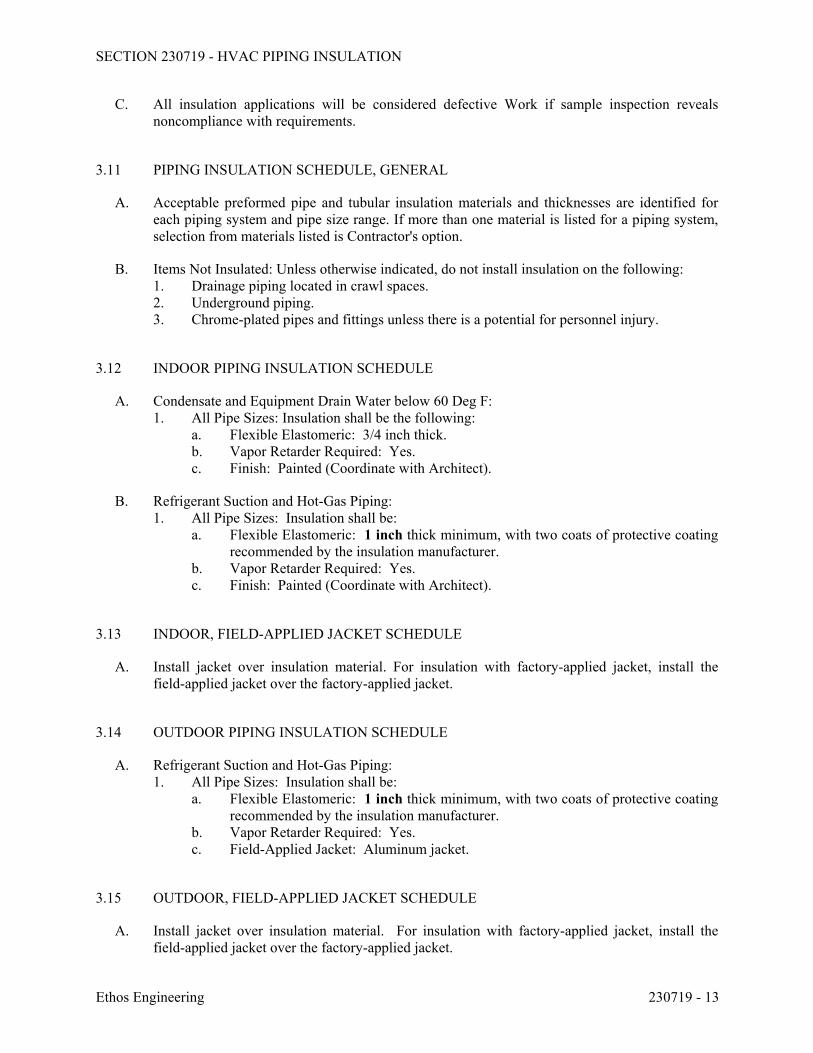
SECTION 230719 - HVAC PIPING INSULATION
Ethos Engineering 230719 - 13
C. All insulation applications will be considered defective Work if sample inspection reveals noncompliance with requirements.
3.11 PIPING INSULATION SCHEDULE, GENERAL
A. Acceptable preformed pipe and tubular insulation materials and thicknesses are identified for each piping system and pipe size range. If more than one material is listed for a piping system, selection from materials listed is Contractor's option.
B. Items Not Insulated: Unless otherwise indicated, do not install insulation on the following: 1. Drainage piping located in crawl spaces. 2. Underground piping. 3. Chrome-plated pipes and fittings unless there is a potential for personnel injury.
3.12 INDOOR PIPING INSULATION SCHEDULE
A. Condensate and Equipment Drain Water below 60 Deg F: 1. All Pipe Sizes: Insulation shall be the following:
a. Flexible Elastomeric: 3/4 inch thick. b. Vapor Retarder Required: Yes. c. Finish: Painted (Coordinate with Architect).
B. Refrigerant Suction and Hot-Gas Piping: 1. All Pipe Sizes: Insulation shall be:
a. Flexible Elastomeric: 1 inch thick minimum, with two coats of protective coating recommended by the insulation manufacturer.
b. Vapor Retarder Required: Yes. c. Finish: Painted (Coordinate with Architect).
3.13 INDOOR, FIELD-APPLIED JACKET SCHEDULE
A. Install jacket over insulation material. For insulation with factory-applied jacket, install the field-applied jacket over the factory-applied jacket.
3.14 OUTDOOR PIPING INSULATION SCHEDULE
A. Refrigerant Suction and Hot-Gas Piping: 1. All Pipe Sizes: Insulation shall be:
a. Flexible Elastomeric: 1 inch thick minimum, with two coats of protective coating recommended by the insulation manufacturer.
b. Vapor Retarder Required: Yes. c. Field-Applied Jacket: Aluminum jacket.
3.15 OUTDOOR, FIELD-APPLIED JACKET SCHEDULE
A. Install jacket over insulation material. For insulation with factory-applied jacket, install the field-applied jacket over the factory-applied jacket.
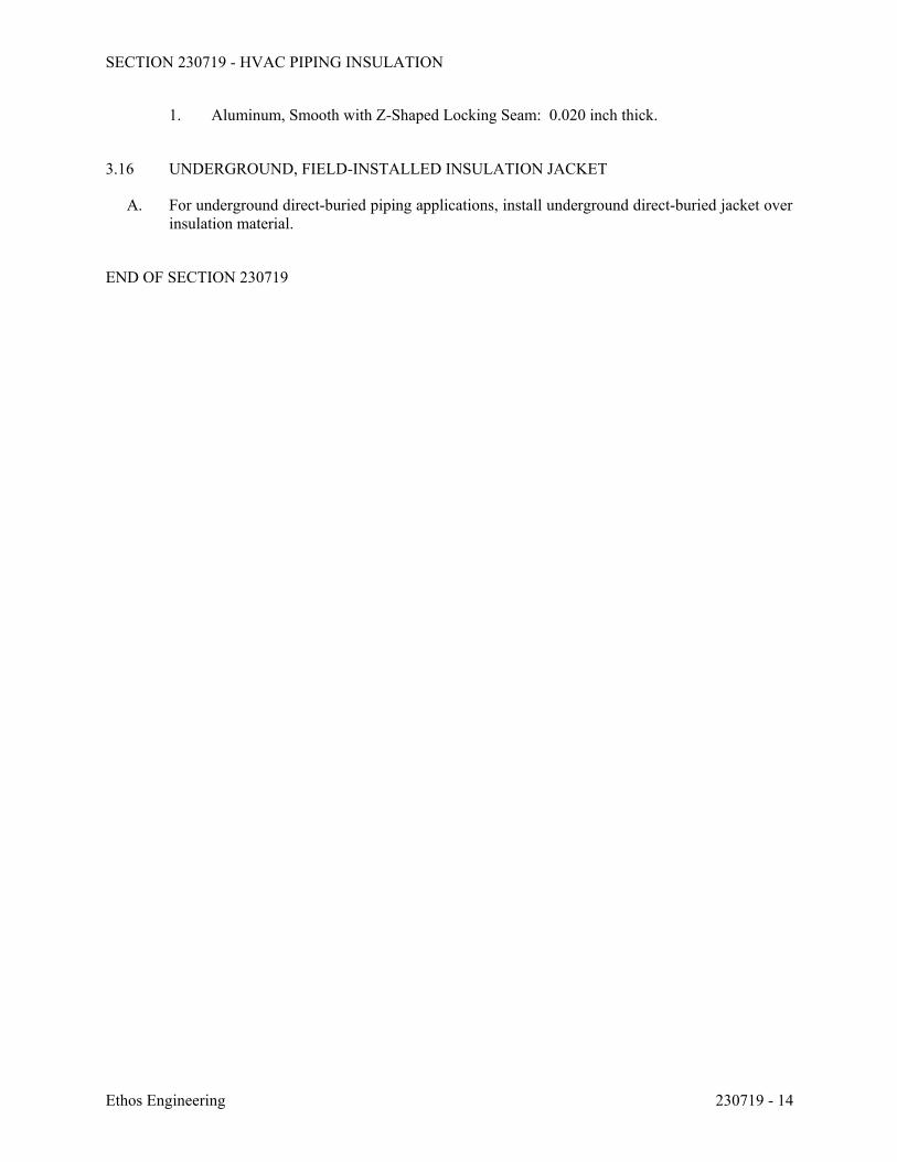
SECTION 230719 - HVAC PIPING INSULATION
Ethos Engineering 230719 - 14
1. Aluminum, Smooth with Z-Shaped Locking Seam: 0.020 inch thick.
3.16 UNDERGROUND, FIELD-INSTALLED INSULATION JACKET
A. For underground direct-buried piping applications, install underground direct-buried jacket over insulation material.
END OF SECTION 230719
SECTION 232300 - REFRIGERANT PIPING
Ethos Engineering 232300 - 1
PART 1 - GENERAL
1.1 RELATED DOCUMENTS
A. Drawings and general provisions of the Contract, including General and Supplementary Conditions and Division 01 Specification Sections, apply to this Section.
1.2 SUMMARY
A. Section Includes:
1. Refrigerant pipes and fittings. 2. Refrigerant piping valves and specialties. 3. Refrigerants.
1.3 ACTION SUBMITTALS
A. Product Data: For each type of valve and refrigerant piping specialty.
1. Include pressure drop, based on manufacturer's test data, for the following:
a. Thermostatic expansion valves. b. Solenoid valves. c. Hot-gas bypass valves. d. Filter dryers. e. Strainers. f. Pressure-regulating valves.
B. Shop Drawings:
1. Show layout of refrigerant piping and specialties, including pipe, tube, and fitting sizes; flow capacities; valve arrangements and locations; slopes of horizontal runs; oil traps; double risers; wall and floor penetrations; and equipment connection details.
2. Show piping size and piping layout, including oil traps, double risers, specialties, and pipe and tube sizes to accommodate, as a minimum, equipment provided, elevation difference between compressor and evaporator, and length of piping to ensure proper operation and compliance with warranties of connected equipment.
3. Show interface and spatial relationships between piping and equipment. 4. Shop Drawing Scale: 1/4 inch equals 1 foot.
1.4 INFORMATIONAL SUBMITTALS
A. Welding certificates.
B. Field quality-control reports.
SECTION 232300 - REFRIGERANT PIPING
Ethos Engineering 232300 - 2
1.5 CLOSEOUT SUBMITTALS
A. Operation and Maintenance Data: For refrigerant valves and piping specialties to include in maintenance manuals.
1.6 QUALITY ASSURANCE
A. Welding Qualifications: Qualify procedures and personnel according to 2010 ASME Boiler and Pressure Vessel Code: Section IX, "Welding and Brazing Qualifications."
B. Comply with ASHRAE 15, "Safety Code for Refrigeration Systems."
C. Comply with ASME B31.5, "Refrigeration Piping and Heat Transfer Components."
1.7 PRODUCT STORAGE AND HANDLING
A. Store piping with end caps in place to ensure that piping interior and exterior are clean when installed.
PART 2 - PRODUCTS
2.1 PERFORMANCE REQUIREMENTS
A. Line Test Pressure for Refrigerant R-134a:
1. Suction Lines for Air-Conditioning Applications: 115 psig. 2. Suction Lines for Heat-Pump Applications: 225 psig. 3. Hot-Gas and Liquid Lines: 225 psig.
B. Line Test Pressure for Refrigerant R-407C:
1. Suction Lines for Air-Conditioning Applications: 230 psig. 2. Suction Lines for Heat-Pump Applications: 380 psig. 3. Hot-Gas and Liquid Lines: 380 psig.
C. Line Test Pressure for Refrigerant R-410A:
1. Suction Lines for Air-Conditioning Applications: 300 psig. 2. Suction Lines for Heat-Pump Applications: 535 psig. 3. Hot-Gas and Liquid Lines: 535 psig.
2.2 COPPER TUBE AND FITTINGS
A. Copper Tube: ASTM B 88, Type L, Type ACR.
B. Wrought-Copper Fittings: ASME B16.22.
SECTION 232300 - REFRIGERANT PIPING
Ethos Engineering 232300 - 3
C. Wrought-Copper Unions: ASME B16.22.
D. Brazing Filler Metals: AWS A5.8/A5.8M.
E. Flexible Connectors:
1. Body: Tin-bronze bellows with woven, flexible, tinned-bronze-wire-reinforced protective jacket.
2. End Connections: Socket ends. 3. Offset Performance: Capable of minimum 3/4-inch misalignment in minimum 7-inch-
long assembly. 4. Working Pressure Rating: Factory test at minimum 500 psig. 5. Maximum Operating Temperature: 250 deg F.
2.3 VALVES AND SPECIALTIES
A. Diaphragm Packless Valves: 1. Body and Bonnet: Forged brass or cast bronze; globe design with straight-through or
angle pattern. 2. Diaphragm: Phosphor bronze and stainless steel with stainless-steel spring. 3. Operator: Rising stem and hand wheel. 4. Seat: Nylon. 5. End Connections: Socket, union, or flanged. 6. Working Pressure Rating: 500 psig. 7. Maximum Operating Temperature: 275 deg F.
B. Packed-Angle Valves: 1. Body and Bonnet: Forged brass or cast bronze. 2. Packing: Molded stem, back seating, and replaceable under pressure. 3. Operator: Rising stem. 4. Seat: Nonrotating, self-aligning polytetrafluoroethylene. 5. Seal Cap: Forged-brass or valox hex cap. 6. End Connections: Socket, union, threaded, or flanged. 7. Working Pressure Rating: 500 psig. 8. Maximum Operating Temperature: 275 deg F.
C. Check Valves: 1. Body: Ductile iron, forged brass, or cast bronze; globe pattern. 2. Bonnet: Bolted ductile iron, forged brass, or cast bronze; or brass hex plug. 3. Piston: Removable polytetrafluoroethylene seat. 4. Closing Spring: Stainless steel. 5. Manual Opening Stem: Seal cap, plated-steel stem, and graphite seal. 6. End Connections: Socket, union, threaded, or flanged. 7. Maximum Opening Pressure: 0.50 psig. 8. Working Pressure Rating: 500 psig. 9. Maximum Operating Temperature: 275 deg F.
D. Service Valves: 1. Body: Forged brass with brass cap including key end to remove core. 2. Core: Removable ball-type check valve with stainless-steel spring.
SECTION 232300 - REFRIGERANT PIPING
Ethos Engineering 232300 - 4
3. Seat: Polytetrafluoroethylene. 4. End Connections: Copper spring. 5. Working Pressure Rating: 500 psig.
E. Solenoid Valves: Comply with AHRI 760 and UL 429; listed and labeled by a National Recognized Testing Laboratory (NRTL). 1. Body and Bonnet: Plated steel. 2. Solenoid Tube, Plunger, Closing Spring, and Seat Orifice: Stainless steel. 3. Seat: Polytetrafluoroethylene. 4. End Connections: Threaded. 5. Electrical: Molded, watertight coil in NEMA 250 enclosure of type required by location
with 1/2-inch conduit adapter, and 24-V ac coil. 6. Working Pressure Rating: 400 psig. 7. Maximum Operating Temperature: 240 deg F.
F. Safety Relief Valves: Comply with 2010 ASME Boiler and Pressure Vessel Code; listed and labeled by an NRTL. 1. Body and Bonnet: Ductile iron and steel, with neoprene O-ring seal. 2. Piston, Closing Spring, and Seat Insert: Stainless steel. 3. Seat: Polytetrafluoroethylene. 4. End Connections: Threaded. 5. Working Pressure Rating: 400 psig. 6. Maximum Operating Temperature: 240 deg F.
G. Thermostatic Expansion Valves: Comply with AHRI 750. 1. Body, Bonnet, and Seal Cap: Forged brass or steel. 2. Diaphragm, Piston, Closing Spring, and Seat Insert: Stainless steel. 3. Packing and Gaskets: Non-asbestos. 4. Capillary and Bulb: Copper tubing filled with refrigerant charge. 5. Suction Temperature: 40 deg F. 6. Reverse-flow option (for heat-pump applications). 7. End Connections: Socket, flare, or threaded union.
H. Hot-Gas Bypass Valves: Comply with UL 429; listed and labeled by an NRTL. 1. Body, Bonnet, and Seal Cap: Ductile iron or steel. 2. Diaphragm, Piston, Closing Spring, and Seat Insert: Stainless steel. 3. Packing and Gaskets: Non-asbestos. 4. Solenoid Tube, Plunger, Closing Spring, and Seat Orifice: Stainless steel. 5. Seat: Polytetrafluoroethylene. 6. Electrical: Molded, watertight coil in NEMA 250 enclosure of type required by location
with 1/2-inch conduit adapter and 24-V ac coil. 7. End Connections: Socket. 8. Throttling Range: Maximum 5 psig. 9. Working Pressure Rating: 500 psig. 10. Maximum Operating Temperature: 240 deg F.
I. Straight-Type Strainers: 1. Body: Welded steel with corrosion-resistant coating. 2. Screen: 100-mesh stainless steel. 3. End Connections: Socket or flare. 4. Working Pressure Rating: 500 psig.
SECTION 232300 - REFRIGERANT PIPING
Ethos Engineering 232300 - 5
5. Maximum Operating Temperature: 275 deg F.
J. Moisture/Liquid Indicators: 1. Body: Forged brass. 2. Window: Replaceable, clear, fused glass window with indicating element protected by
filter screen. 3. Indicator: Color coded to show moisture content in parts per million (ppm). 4. Minimum Moisture Indicator Sensitivity: Indicate moisture above 60 ppm. 5. End Connections: Socket or flare. 6. Working Pressure Rating: 500 psig. 7. Maximum Operating Temperature: 240 deg F.
K. Permanent Filter Dryers: Comply with AHRI 730. 1. Body and Cover: Painted-steel shell. 2. Filter Media: 10 micron, pleated with integral end rings; stainless-steel support. 3. Desiccant Media: Activated alumina, charcoal. 4. Designed for reverse flow (for heat-pump applications). 5. End Connections: Socket. 6. Access Ports: NPS 1/4 connections at entering and leaving sides for pressure differential
measurement. 7. Working Pressure Rating: 500 psig. 8. Maximum Operating Temperature: 240 deg F.
L. Receivers: Comply with AHRI 495.
1. Comply with 2010 ASME Boiler and Pressure Vessel Code; listed and labeled by an NRTL.
2. Comply with UL 207; listed and labeled by an NRTL. 3. Body: Welded steel with corrosion-resistant coating. 4. Tappings: Inlet, outlet, liquid level indicator, and safety relief valve. 5. End Connections: Socket or threaded. 6. Working Pressure Rating: 500 psig. 7. Maximum Operating Temperature: 275 deg F.
M. Liquid Accumulators: Comply with AHRI 495. 1. Body: Welded steel with corrosion-resistant coating. 2. End Connections: Socket or threaded. 3. Working Pressure Rating: 500 psig. 4. Maximum Operating Temperature: 275 deg F.
2.4 REFRIGERANTS
A. Manufacturers: Subject to compliance with requirements, provide products by one of the following: 1. Arkema Inc. 2. DuPont Fluorochemicals Div. 3. Genetron Refrigerants; Honeywell International Inc. 4. Mexichem Fluor Inc.
B. ASHRAE 34, R-134a: Tetrafluoroethane.
SECTION 232300 - REFRIGERANT PIPING
Ethos Engineering 232300 - 6
C. ASHRAE 34, R-407C: Difluoromethane/Pentafluoroethane/1,1,1,2-Tetrafluoroethane.
D. ASHRAE 34, R-410A: Pentafluoroethane/Difluoromethane.
2.5 REFRIGERANT PIPING SUPPORT EXTERIOR TO BUILDING
A. Exterior: Pre-manufactured strut supports; 3/8” stainless steel threaded rods holding 7” long aluminum cross-strut, stainless steel bolts, 3” to 6” adjustable height, molded 33% fiberglass reinforced nylon support base; UV stabilized. MAPA Products, type MS-2 or MS-3.
PART 3 - EXECUTION
3.1 PIPING APPLICATIONS
A. Suction Lines NPS 1-1/2 and Smaller for Conventional Air-Conditioning Applications: Copper, Type ACR, annealed-temper tubing and wrought-copper fittings with brazed joints.
B. Suction Lines NPS 2 to NPS 4 for Conventional Air-Conditioning Applications: Copper, Type ACR, drawn-temper tubing and wrought-copper fittings with brazed joints.
C. Hot-Gas and Liquid Lines, and Suction Lines for Heat-Pump Applications: Copper, Type ACR, annealed-temper tubing and wrought-copper fittings with brazed joints.
D. Safety-Relief-Valve Discharge Piping: Schedule 40, black-steel and wrought-steel fittings with welded joints.
E. Safety-Relief-Valve Discharge Piping: Copper, Type ACR, drawn-temper tubing and wrought-copper fittings with soldered joints.
F. Safety-Relief-Valve Discharge Piping: Copper, Type ACR, annealed-temper tubing and wrought-copper fittings with brazed joints.
3.2 VALVE AND SPECIALTY APPLICATIONS
A. Install diaphragm packless valves in suction and discharge lines of compressor.
B. Install service valves for gage taps at inlet and outlet of hot-gas bypass valves and strainers if they are not an integral part of valves and strainers.
C. Install a check valve at the compressor discharge and a liquid accumulator at the compressor suction connection.
D. Except as otherwise indicated, install diaphragm packless valves on inlet and outlet side of filter dryers.
E. Install a full-size, three-valve bypass around filter dryers.
SECTION 232300 - REFRIGERANT PIPING
Ethos Engineering 232300 - 7
F. Install solenoid valves upstream from each expansion valve and hot-gas bypass valve. Install solenoid valves in horizontal lines with coil at top.
G. Install thermostatic expansion valves as close as possible to distributors on evaporators.
1. Install valve so diaphragm case is warmer than bulb. 2. Secure bulb to clean, straight, horizontal section of suction line using two bulb straps. Do
not mount bulb in a trap or at bottom of the line. 3. If external equalizer lines are required, make connection where it will reflect suction-line
pressure at bulb location.
H. Install safety relief valves where required by 2010 ASME Boiler and Pressure Vessel Code. Pipe safety-relief-valve discharge line to outside according to ASHRAE 15.
I. Install moisture/liquid indicators in liquid line at the inlet of the thermostatic expansion valve or at the inlet of the evaporator coil capillary tube.
J. Install strainers upstream from and adjacent to the following unless they are furnished as an integral assembly for the device being protected:
1. Solenoid valves. 2. Thermostatic expansion valves. 3. Hot-gas bypass valves. 4. Compressor.
K. Install filter dryers in liquid line between compressor and thermostatic expansion valve, and in the suction line at the compressor.
L. Install receivers sized to accommodate pump-down charge.
M. Install flexible connectors at compressors.
3.3 PIPING INSTALLATION
A. Drawing plans, schematics, and diagrams indicate general location and arrangement of piping systems; indicated locations and arrangements were used to size pipe and calculate friction loss, expansion, pump sizing, and other design considerations. Install piping as indicated unless deviations to layout are approved on Shop Drawings.
B. Install refrigerant piping according to ASHRAE 15.
C. Install piping in concealed locations unless otherwise indicated and except in equipment rooms and service areas.
D. Install piping indicated to be exposed and piping in equipment rooms and service areas at right angles or parallel to building walls. Diagonal runs are prohibited unless specifically indicated otherwise.
E. Install piping above accessible ceilings to allow sufficient space for ceiling panel removal.
F. Install piping adjacent to machines to allow service and maintenance.
SECTION 232300 - REFRIGERANT PIPING
Ethos Engineering 232300 - 8
G. Install piping free of sags and bends.
H. Install fittings for changes in direction and branch connections.
I. Select system components with pressure rating equal to or greater than system operating pressure.
J. Refer to Section 230923 "Direct Digital Control (DDC) System for HVAC" and Section 230993.11 "Sequence of Operations for HVAC DDC" for solenoid valve controllers, control wiring, and sequence of operation.
K. Install piping as short and direct as possible, with a minimum number of joints, elbows, and fittings.
L. Arrange piping to allow inspection and service of refrigeration equipment. Install valves and specialties in accessible locations to allow for service and inspection. Install access doors or panels as specified in Section 083113 "Access Doors and Frames" if valves or equipment requiring maintenance is concealed behind finished surfaces.
M. Install refrigerant piping in protective conduit where installed belowground.
N. Install refrigerant piping in rigid or flexible conduit in locations where exposed to mechanical injury.
O. Slope refrigerant piping as follows:
1. Install horizontal hot-gas discharge piping with a uniform slope downward away from compressor.
2. Install horizontal suction lines with a uniform slope downward to compressor. 3. Install traps and double risers to entrain oil in vertical runs. 4. Liquid lines may be installed level.
P. When brazing or soldering, remove solenoid-valve coils and sight glasses; also remove valve stems, seats, and packing, and accessible internal parts of refrigerant specialties. Do not apply heat near expansion-valve bulb.
Q. Before installation of steel refrigerant piping, clean pipe and fittings using the following procedures:
1. Shot blast the interior of piping. 2. Remove coarse particles of dirt and dust by drawing a clean, lintless cloth through tubing
by means of a wire or electrician's tape. 3. Draw a clean, lintless cloth saturated with trichloroethylene through the tube or pipe.
Continue this procedure until cloth is not discolored by dirt. 4. Draw a clean, lintless cloth, saturated with compressor oil, squeezed dry, through the tube
or pipe to remove remaining lint. Inspect tube or pipe visually for remaining dirt and lint. 5. Finally, draw a clean, dry, lintless cloth through the tube or pipe. 6. Safety-relief-valve discharge piping is not required to be cleaned but is required to be
open to allow unrestricted flow.
SECTION 232300 - REFRIGERANT PIPING
Ethos Engineering 232300 - 9
R. Install piping with adequate clearance between pipe and adjacent walls and hangers or between pipes for insulation installation.
S. Identify refrigerant piping and valves according to Section 230553 "Identification for HVAC Piping and Equipment."
T. Install sleeves for piping penetrations of walls, ceilings, and floors. Comply with requirements for sleeves specified in Section 230517 "Sleeves and Sleeve Seals for HVAC Piping."
U. Install sleeve seals for piping penetrations of concrete walls and slabs. Comply with requirements for sleeve seals specified in Section 230517 "Sleeves and Sleeve Seals for HVAC Piping."
V. Install escutcheons for piping penetrations of walls, ceilings, and floors. Comply with requirements for escutcheons specified in Section 230518 "Escutcheons for HVAC Piping."
3.4 PIPE JOINT CONSTRUCTION
A. Ream ends of pipes and tubes and remove burrs. Bevel plain ends of steel pipe.
B. Remove scale, slag, dirt, and debris from inside and outside of pipe and fittings before assembly.
C. Fill pipe and fittings with an inert gas (nitrogen or carbon dioxide), during brazing or welding, to prevent scale formation.
D. Soldered Joints: Construct joints according to ASTM B 828 or CDA's "Copper Tube Handbook."
E. Brazed Joints: Construct joints according to AWS's "Brazing Handbook," Chapter "Pipe and Tube."
1. Use Type BCuP (copper-phosphorus) alloy for joining copper socket fittings with copper pipe.
2. Use Type BAg (cadmium-free silver) alloy for joining copper with bronze or steel.
F. Threaded Joints: Thread steel pipe with tapered pipe threads according to ASME B1.20.1. Cut threads full and clean using sharp dies. Ream threaded pipe ends to remove burrs and to restore full ID. Join pipe fittings and valves as follows:
1. Apply appropriate tape or thread compound to external pipe threads unless dry-seal threading is specified.
2. Damaged Threads: Do not use pipe or pipe fittings with threads that are corroded or damaged. Do not use pipe sections that have cracked or open welds.
G. Welded Joints: Construct joints according to AWS D10.12M/D10.12.
H. Flanged Joints: Select appropriate gasket material, size, type, and thickness for service application. Install gasket concentrically positioned. Use suitable lubricants on bolt threads.
SECTION 232300 - REFRIGERANT PIPING
Ethos Engineering 232300 - 10
3.5 HANGERS AND SUPPORTS
A. Comply with requirements for pipe hangers and supports specified in Section 230529 "Hangers and Supports for HVAC Piping and Equipment."
B. Install the following pipe attachments:
1. Adjustable steel clevis hangers for individual horizontal runs less than 20 feet long. 2. Roller hangers and spring hangers for individual horizontal runs 20 feet or longer. 3. Pipe Roller: MSS SP-58, Type 44 for multiple horizontal piping 20 feet or longer,
supported on a trapeze. 4. Spring hangers to support vertical runs. 5. Copper-clad hangers and supports for hangers and supports in direct contact with copper
pipe.
C. Install hangers for copper tubing with the following maximum spacing and minimum rod diameters:
1. NPS 1/2: Maximum span, 60 inches; minimum rod, 1/4 inch. 2. NPS 5/8: Maximum span, 60 inches; minimum rod, 1/4 inch. 3. NPS 1: Maximum span, 72 inches; minimum rod, 1/4 inch. 4. NPS 1-1/4: Maximum span, 96 inches; minimum rod, 3/8 inch. 5. NPS 1-1/2: Maximum span, 96 inches; minimum rod, 3/8 inch. 6. NPS 2: Maximum span, 96 inches; minimum rod, 3/8 inch. 7. NPS 2-1/2: Maximum span, 108 inches; minimum rod, 3/8 inch. 8. NPS 3: Maximum span, 10 feet; minimum rod, 3/8 inch. 9. NPS 4: Maximum span, 12 feet; minimum rod, 1/2 inch.
D. Support multifloor vertical runs at least at each floor.
3.6 FIELD QUALITY CONTROL
A. Perform the following tests and inspections:
1. Comply with ASME B31.5, Chapter VI. 2. Test refrigerant piping, specialties, and receivers. Isolate compressor, condenser,
evaporator, and safety devices from test pressure if they are not rated above the test pressure.
3. Test high- and low-pressure side piping of each system separately at not less than the pressures indicated in "Performance Requirements" Article.
a. Fill system with nitrogen to the required test pressure. b. System shall maintain test pressure at the manifold gage throughout duration of
test. c. Test joints and fittings with electronic leak detector or by brushing a small amount
of soap and glycerin solution over joints. d. Remake leaking joints using new materials, and retest until satisfactory results are
achieved.
B. Prepare test and inspection reports.
SECTION 232300 - REFRIGERANT PIPING
Ethos Engineering 232300 - 11
3.7 SYSTEM CHARGING
A. Charge system using the following procedures:
1. Install core in filter dryers after leak test but before evacuation. 2. Evacuate entire refrigerant system with a vacuum pump to 500 micrometers. If vacuum
holds for 12 hours, system is ready for charging. 3. Break vacuum with refrigerant gas, allowing pressure to build up to 2 psig. 4. Charge system with a new filter-dryer core in charging line.
3.8 ADJUSTING
A. Adjust thermostatic expansion valve to obtain proper evaporator superheat.
B. Adjust high- and low-pressure switch settings to avoid short cycling in response to fluctuating suction pressure.
C. Adjust set-point temperature of air-conditioning or chilled-water controllers to the system design temperature.
D. Perform the following adjustments before operating the refrigeration system, according to manufacturer's written instructions:
1. Open shutoff valves in condenser water circuit. 2. Verify that compressor oil level is correct. 3. Open compressor suction and discharge valves. 4. Open refrigerant valves except bypass valves that are used for other purposes. 5. Check open compressor-motor alignment and verify lubrication for motors and bearings.
E. Replace core of replaceable filter dryer after system has been adjusted and after design flow rates and pressures are established.
END OF SECTION 232300
SECTION 233113 - METAL DUCTS
Ethos Engineering 233113 - 1
PART 1 - GENERAL
1.1 RELATED DOCUMENTS
A. Drawings and general provisions of the Contract, including General and Supplementary Conditions and Division 01 Specification Sections, apply to this Section.
1.2 SUMMARY
A. Section Includes: 1. Single-wall rectangular ducts and fittings. 2. Single-wall round ducts and fittings. 3. Sheet metal materials. 4. Duct liner. 5. Sealants and gaskets. 6. Hangers and supports.
B. Related Sections: 1. Section 230593 "Testing, Adjusting, and Balancing for HVAC" for testing, adjusting, and
balancing requirements for metal ducts. 2. Section 233300 "Air Duct Accessories" for dampers, sound-control devices, duct-
mounting access doors and panels, turning vanes, and flexible ducts.
1.3 PERFORMANCE REQUIREMENTS
A. Delegated Duct Design: Duct construction, including sheet metal thicknesses, seam and joint construction, reinforcements, and hangers and supports, shall comply with SMACNA's "HVAC Duct Construction Standards - Metal and Flexible" and performance requirements and design criteria indicated in "Duct Schedule" Article.
B. Structural Performance: Duct hangers and supports shall withstand the effects of gravity loads and stresses within limits and under conditions described in SMACNA's "HVAC Duct Construction Standards - Metal and Flexible"
C. Airstream Surfaces: Surfaces in contact with the airstream shall comply with requirements in ASHRAE 62.1.
D. Duct system design, as indicated, has been used to select size and type of air-moving and -distribution equipment and other air system components. Changes to layout or configuration of duct system must be specifically approved in writing by Architect. Accompany requests for layout modifications with calculations showing that proposed layout will provide original design results without increasing system total pressure.
1.4 ACTION SUBMITTALS
A. Product Data: For each type of the following products:
SECTION 233113 - METAL DUCTS
Ethos Engineering 233113 - 2
1. Liners and adhesives. 2. Sealants and gaskets. 3. Fire-Stopping Materials.
B. Shop Drawings: 1. Fabrication, assembly, and installation, including plans, elevations, sections, components,
and attachments to other work. 2. Factory- and shop-fabricated ducts and fittings. 3. Duct layout indicating sizes, configuration, liner material, and static-pressure classes. 4. Elevation of top of ducts. 5. Dimensions of main duct runs from building grid lines. 6. Fittings. 7. Reinforcement and spacing. 8. Seam and joint construction. 9. Penetrations through fire-rated and other partitions. 10. Equipment installation based on equipment being used on Project. 11. Locations for duct accessories, including dampers, turning vanes, and access doors and
panels. 12. Hangers and supports, including methods for duct and building attachment and vibration
isolation.
C. Delegated-Design Submittal: 1. Sheet metal thicknesses. 2. Joint and seam construction and sealing. 3. Reinforcement details and spacing. 4. Materials, fabrication, assembly, and spacing of hangers and supports.
1.5 INFORMATIONAL SUBMITTALS
A. Coordination Drawings: Plans, drawn to scale, on which the following items are shown and coordinated with each other, using input from installers of the items involved: 1. Duct installation in congested spaces, indicating coordination with general construction,
building components, and other building services. Indicate proposed changes to duct layout.
2. Suspended ceiling components. 3. Structural members to which duct will be attached. 4. Size and location of initial access modules for acoustical tile. 5. Penetrations of smoke barriers and fire-rated construction. 6. Items penetrating finished ceiling including the following:
a. Lighting fixtures. b. Air outlets and inlets. c. Speakers. d. Sprinklers. e. Access panels. f. Perimeter moldings.
B. Welding certificates.
C. Field quality-control reports.
SECTION 233113 - METAL DUCTS
Ethos Engineering 233113 - 3
1.6 QUALITY ASSURANCE
A. Welding Qualifications: Qualify procedures and personnel according to AWS D1.1/D1.1M, "Structural Welding Code - Steel," for hangers and supports. AWS D9.1M/D9.1, "Sheet Metal Welding Code," for duct joint and seam welding.
B. Welding Qualifications: Qualify procedures and personnel according to the following: 1. AWS D1.1/D1.1M, "Structural Welding Code - Steel," for hangers and supports. 2. AWS D9.1M/D9.1, "Sheet Metal Welding Code," for duct joint and seam welding.
C. ASHRAE Compliance: Applicable requirements in ASHRAE 62.1, Section 5 - "Systems and Equipment" and Section 7 - "Construction and System Start-up."
D. ASHRAE/IESNA Compliance: Applicable requirements in ASHRAE/IESNA 90.1, Section 6.4.4 - "HVAC System Construction and Insulation."
PART 2 - PRODUCTS
2.1 SINGLE-WALL RECTANGULAR DUCTS AND FITTINGS
A. General Fabrication Requirements: Comply with SMACNA's "HVAC Duct Construction Standards - Metal and Flexible" based on indicated static-pressure class unless otherwise indicated.
B. Transverse Joints: Select joint types and fabricate according to SMACNA's "HVAC Duct Construction Standards - Metal and Flexible," Figure 2-1, "Rectangular Duct/Transverse Joints," for static-pressure class, applicable sealing requirements, materials involved, duct-support intervals, and other provisions in SMACNA's "HVAC Duct Construction Standards - Metal and Flexible."
C. Longitudinal Seams: Select seam types and fabricate according to SMACNA's "HVAC Duct Construction Standards - Metal and Flexible," Figure 2-2, "Rectangular Duct/Longitudinal Seams," for static-pressure class, applicable sealing requirements, materials involved, duct-support intervals, and other provisions in SMACNA's "HVAC Duct Construction Standards - Metal and Flexible."
D. Elbows, Transitions, Offsets, Branch Connections, and Other Duct Construction: Select types and fabricate according to SMACNA's "HVAC Duct Construction Standards - Metal and Flexible," Chapter 4, "Fittings and Other Construction," for static-pressure class, applicable sealing requirements, materials involved, duct-support intervals, and other provisions in SMACNA's "HVAC Duct Construction Standards - Metal and Flexible."
2.2 SINGLE-WALL ROUND DUCTS AND FITTINGS
A. Round, Spiral Lock-Seam Ducts.
B. General Fabrication Requirements: Comply with SMACNA's "HVAC Duct Construction Standards - Metal and Flexible," Chapter 3, "Round, Oval, and Flexible Duct," based on indicated static-pressure class unless otherwise indicated.
SECTION 233113 - METAL DUCTS
Ethos Engineering 233113 - 4
1. Manufacturers: a. Lindab Inc. b. McGill AirFlow LLC. c. SEMCO Incorporated. d. Sheet Metal Connectors, Inc. e. Spiral Manufacturing Co., Inc.
C. Flat-Oval Ducts: Indicated dimensions are the duct width (major dimension) and diameter of the round sides connecting the flat portions of the duct (minor dimension).
D. Duct Joints: 1. Ducts up to 20 Inches in Diameter: Interior, center-beaded slip coupling, sealed before
and after fastening, attached with sheet metal screws. 2. Ducts 21 to 72 Inchesin Diameter: Three-piece, gasketed, flanged joint consisting of two
internal flanges with sealant and one external closure band with gasket. 3. Round Ducts: Prefabricated connection system consisting of double-lipped, EPDM
rubber gasket. Manufacture ducts according to connection system manufacturer's tolerances. a. Manufacturers:
1) Ductmate Industries, Inc. 2) Lindab Inc.
E. 90-Degree Tees and Laterals and Conical Tees: Fabricate to comply with SMACNA's "HVAC Duct Construction Standards--Metal and Flexible," with metal thicknesses specified for longitudinal-seam straight ducts.
F. Diverging-Flow Fittings: Fabricate with reduced entrance to branch taps and with no excess material projecting from fitting onto branch tap entrance.
G. Fabricate elbows using die-formed, gored, pleated, or mitered construction. Unless elbow construction type is indicated, fabricate elbows as follows: 1. Mitered-Elbow Radius and Number of Pieces: Welded construction complying with
SMACNA's "HVAC Duct Construction Standards--Metal and Flexible," unless otherwise indicated.
2. Round Mitered Elbows with Aerofoil Vanes: Welded construction with the following metal thickness for pressure classes from minus 2- to plus 2-inch wg: a. Ducts 3 to 36 Inches in Diameter: 0.034 inch. b. Ducts 37 to 50 Inches in Diameter: 0.040 inch.
3. 90-Degree, 2-Piece, Mitered Elbows: Use only for supply systems or for material-
handling Class A or B exhaust systems and only where space restrictions do not permit using radius elbows. Fabricate with single-thickness turning vanes.
4. Round Elbows 8 Inchesand Less in Diameter: Fabricate die-formed elbows for 45- and 90-degree elbows and pleated elbows for 30, 45, 60, and 90 degrees only. Fabricate nonstandard bend-angle configurations or nonstandard diameter elbows with gored construction.
5. Round Elbows 9 through 14 Inchesin Diameter: Fabricate gored or pleated elbows for 30, 45, 60, and 90 degrees unless space restrictions require mitered elbows. Fabricate nonstandard bend-angle configurations or nonstandard diameter elbows with gored construction.
SECTION 233113 - METAL DUCTS
Ethos Engineering 233113 - 5
6. Round Elbows Larger than 14 Inches in Diameter and All Flat-Oval Elbows: Fabricate gored elbows unless space restrictions require mitered elbows.
7. Die-Formed Elbows for Sizes through 8 Inches in Diameter and All Pressures 0.040 inch thick with 2-piece welded construction.
8. Round Gored-Elbow Metal Thickness: Same as non-elbow fittings specified above. 9. Pleated Elbows for Sizes through 14 Inchesin Diameter and Pressures through 10-Inch
wg: 0.022 inch.
2.3 SHEET METAL MATERIALS
A. General Material Requirements: Comply with SMACNA's "HVAC Duct Construction Standards - Metal and Flexible" for acceptable materials, material thicknesses, and duct construction methods unless otherwise indicated. Sheet metal materials shall be free of pitting, seam marks, roller marks, stains, discolorations, and other imperfections.
B. Galvanized Sheet Steel: Comply with ASTM A 653/A 653M. 1. Galvanized Coating Designation: G90. 2. Finishes for Surfaces Exposed to View: Mill phosphatized.
C. Carbon-Steel Sheets: Comply with ASTM A 1008/A 1008M, with oiled, matte finish for exposed ducts.
D. Stainless-Steel Sheets: Comply with ASTM A 480/A 480M, Type 304 or 316, as indicated in the "Duct Schedule" Article; cold rolled, annealed, sheet. Exposed surface finish shall be No. 2B, No. 2D, No. 3, or No. 4 as indicated in the "Duct Schedule" Article.
E. Reinforcement Shapes and Plates: ASTM A 36/A 36M, steel plates, shapes, and bars; black and galvanized. 1. Where black- and galvanized-steel shapes and plates are used to reinforce aluminum
ducts, isolate the different metals with butyl rubber, neoprene, or EPDM gasket materials.
F. Tie Rods: Galvanized steel, 1/4-inch minimum diameter for lengths 36 inches or less; 3/8-inch minimum diameter for lengths longer than 36 inches.
2.4 DUCT LINER
A. Fibrous-Glass Duct Liner: Comply with ASTM C 1071, NFPA 90A, or NFPA 90B; and with NAIMA AH124, "Fibrous Glass Duct Liner Standard." 1. Manufacturers:
a. Owens Corning’s Aeroflex Plus Duct Liner or Equal.
2. Materials: ASTM C 1071; surfaces exposed to airstream shall be coated to prevent erosion of glass fibers. a. Maximum Thermal Conductivity: b. Thickness: 1 inch for sound attenuation, and R8 for thermal insulation. c. Thermal Conductivity (k-Value): 0.26 at 75 deg Fmean temperature. d. Fire-Hazard Classification: Maximum flame-spread index of 25 and smoke-
developed index of 50 when tested according to ASTM E84.
SECTION 233113 - METAL DUCTS
Ethos Engineering 233113 - 6
e. Water-Based Liner Adhesive: As recommended by insulation manufacturer and complying with NFPA 90A or NFPA 90B. For indoor applications, use adhesive that has a VOC content of 80 g/L or less when calculated according to 40 CFR 59, Subpart D (EPA Method 24).
f. Mechanical Fasteners: Galvanized steel suitable for adhesive attachment, mechanical attachment, or welding attachment to duct without damaging liner when applied as recommended by manufacturer and without causing leakage in duct. 1) Tensile Strength: Indefinitely sustain a 50-lb-tensile, dead-load test
perpendicular to duct wall. 2) Fastener Pin Length: As required for thickness of insulation and without
projecting more than 1/8 inch into airstream. 3) Adhesive for Attaching Mechanical Fasteners: Comply with fire-hazard
classification of duct liner system.
3. Antimicrobial Erosion-Resistant Coating: Apply to the surface of the liner that will form the interior surface of the duct to act as a moisture repellent and erosion-resistant coating. Antimicrobial compound shall be tested for efficacy by an NRTL and registered by the EPA for use in HVAC systems.
2.5 SEALANT AND GASKETS
A. General Sealant and Gasket Requirements: Surface-burning characteristics for sealants and gaskets shall be a maximum flame-spread index of 25 and a maximum smoke-developed index of 50 when tested according to UL 723; certified by an NRTL.
B. Two-Part Tape Sealing System: 1. Tape: Woven cotton fiber impregnated with mineral gypsum and modified
acrylic/silicone activator to react exothermically with tape to form hard, durable, airtight seal.
2. Tape Width: 4 inches. 3. Sealant: Modified styrene acrylic. 4. Water resistant. 5. Mold and mildew resistant. 6. Maximum Static-Pressure Class: 10-inch wg, positive and negative. 7. Service: Indoor and outdoor. 8. Service Temperature: Minus 40 to plus 200 deg F. 9. Substrate: Compatible with galvanized sheet steel (both PVC coated and bare), stainless
steel, or aluminum. 10. For indoor applications, sealant shall have a VOC content of 250 g/L or less when
calculated according to 40 CFR 59, Subpart D (EPA Method 24). 11. Sealant shall comply with the testing and product requirements of the California
Department of Health Services' "Standard Practice for the Testing of Volatile Organic Emissions from Various Sources Using Small-Scale Environmental Chambers."
C. Water-Based Joint and Seam Sealant: 1. Application Method: Brush on. 2. Solids Content: Minimum 65 percent. 3. Shore A Hardness: Minimum 20. 4. Water resistant.
SECTION 233113 - METAL DUCTS
Ethos Engineering 233113 - 7
5. Mold and mildew resistant. 6. VOC: Maximum 75 g/L (less water). 7. Maximum Static-Pressure Class: 10-inch wg, positive and negative. 8. Service: Indoor or outdoor. 9. Substrate: Compatible with galvanized sheet steel (both PVC coated and bare), stainless
steel, or aluminum sheets.
D. Flanged Joint Sealant: Comply with ASTM C 920. 1. General: Single-component, acid-curing, silicone, elastomeric. 2. Type: S. 3. Grade: NS. 4. Class: 25. 5. Use: O. 6. For indoor applications, sealant shall have a VOC content of 250 g/L or less when
calculated according to 40 CFR 59, Subpart D (EPA Method 24). 7. Sealant shall comply with the testing and product requirements of the California
Department of Health Services' "Standard Practice for the Testing of Volatile Organic Emissions from Various Sources Using Small-Scale Environmental Chambers."
E. Flange Gaskets: Butyl rubber, neoprene, or EPDM polymer with polyisobutylene plasticizer.
F. Round Duct Joint O-Ring Seals: 1. Seal shall provide maximum 3 cfm/100 sq. ft. at 1-inch wg and shall be rated for10-inch
wg static-pressure class, positive or negative. 2. EPDM O-ring to seal in concave bead in coupling or fitting spigot. 3. Double-lipped, EPDM O-ring seal, mechanically fastened to factory-fabricated couplings
and fitting spigots.
2.6 HANGERS AND SUPPORTS
A. Hanger Rods for Noncorrosive Environments: Cadmium-plated steel rods and nuts.
B. Hanger Rods for Corrosive Environments: Electrogalvanized, all-thread rods or galvanized rods with threads painted with zinc-chromate primer after installation.
C. Strap and Rod Sizes: Comply with SMACNA's "HVAC Duct Construction Standards - Metal and Flexible," Table 5-1, "Rectangular Duct Hangers Minimum Size," and Table 5-2, "Minimum Hanger Sizes for Round Duct."
D. Steel Cables for Galvanized-Steel Ducts: Galvanized steel complying with ASTM A 603.
E. Steel Cables for Stainless-Steel Ducts: Stainless steel complying with ASTM A 492.
F. Steel Cable End Connections: Cadmium-plated steel assemblies with brackets, swivel, and bolts designed for duct hanger service; with an automatic-locking and clamping device.
G. Duct Attachments: Sheet metal screws, blind rivets, or self-tapping metal screws; compatible with duct materials.
H. Trapeze and Riser Supports:
SECTION 233113 - METAL DUCTS
Ethos Engineering 233113 - 8
1. Supports for Galvanized-Steel Ducts: Galvanized-steel shapes and plates. 2. Supports for Stainless-Steel Ducts: Stainless-steel shapes and plates. 3. Supports for Aluminum Ducts: Aluminum or galvanized steel coated with zinc chromate.
2.7 FIRE-STOPPING
A. Fire-Resistant Sealant: Provide two-part, foamed-in-place, fire-stopping silicone sealant, one-part elastomeric sealant, formulated for use in a through-penetration fire-stop system for filling openings around duct penetrations through walls and floors, having fire-resistance ratings indicated as established by testing identical assemblies per ASTM E 814 by Underwriters Laboratory, Inc. or other testing and inspecting agency acceptable to authorities having jurisdiction.
B. Products: Subject to compliance with requirements, products that may be incorporated in the Work are limited to, the following: 1. "Dow Corning Fire Stop Foam"; Dow Corning Corp. 2. "Dow Corning Fire Stop Sealant"; Dow Corning Corp. 3. "3M Fire Barrier Caulk CP-25"; Electrical Products Div./3M.
C. Seams and laps arranged on top of duct.
PART 3 - EXECUTION
3.1 DUCT INSTALLATION
A. Drawing plans, schematics, and diagrams indicate general location and arrangement of duct system. Indicated duct locations, configurations, and arrangements were used to size ducts and calculate friction loss for air-handling equipment sizing and for other design considerations. Install duct systems as indicated unless deviations to layout are approved on Shop Drawings and Coordination Drawings.
B. Install ducts according to SMACNA's "HVAC Duct Construction Standards - Metal and Flexible" unless otherwise indicated.
C. Install round and flat-oval ducts in maximum practical lengths.
D. Install ducts with fewest possible joints.
E. Install factory- or shop-fabricated fittings for changes in direction, size, and shape and for branch connections.
F. Unless otherwise indicated, install ducts vertically and horizontally, and parallel and perpendicular to building lines.
G. Install ducts close to walls, overhead construction, columns, and other structural and permanent enclosure elements of building.
H. Install ducts with a clearance of 1 inch, plus allowance for insulation thickness.
SECTION 233113 - METAL DUCTS
Ethos Engineering 233113 - 9
I. Route ducts to avoid passing through transformer vaults and electrical equipment rooms and enclosures.
J. Where ducts pass through non-fire-rated interior partitions and exterior walls and are exposed to view, cover the opening between the partition and duct or duct insulation with sheet metal flanges of same metal thickness as the duct. Overlap openings on four sides by at least 1-1/2 inches.
K. Where ducts pass through fire-rated interior partitions and exterior walls, install fire dampers. Comply with requirements in Section 233300 "Air Duct Accessories" for fire and smoke dampers.
L. Protect duct interiors from moisture, construction debris and dust, and other foreign materials. Comply with SMACNA's "IAQ Guidelines for Occupied Buildings Under Construction," Appendix G, "Duct Cleanliness for New Construction Guidelines."
3.2 INSTALLATION OF EXPOSED DUCTWORK
A. Protect ducts exposed in finished spaces from being dented, scratched, or damaged.
B. Trim duct sealants flush with metal. Create a smooth and uniform exposed bead. Do not use two-part tape sealing system.
C. Grind welds to provide smooth surface free of burrs, sharp edges, and weld splatter. When welding stainless steel with a No. 3 or 4 finish, grind the welds flush, polish the exposed welds, and treat the welds to remove discoloration caused by welding.
D. Maintain consistency, symmetry, and uniformity in the arrangement and fabrication of fittings, hangers and supports, duct accessories, and air outlets.
E. Repair or replace damaged sections and finished work that does not comply with these requirements.
3.3 APPLICATION OF LINER IN RECTANGULAR DUCTS
A. Adhere a single layer of indicated thickness of duct liner with at least 90 percent adhesive coverage at liner contact surface area. Attaining indicated thickness with multiple layers of duct liner is prohibited.
B. Apply adhesive to transverse edges of liner facing upstream that do not receive metal nosing.
C. Butt transverse joints without gaps and coat joint with adhesive.
D. Fold and compress liner in corners of rectangular ducts or cut and fit to ensure butted-edge overlapping.
E. Do not apply liner in rectangular ducts with longitudinal joints, except at corners of ducts, unless duct size and standard liner product dimensions make longitudinal joints necessary.
F. Apply adhesive coating on longitudinal seams in ducts with air velocity of 2500 fpm.
SECTION 233113 - METAL DUCTS
Ethos Engineering 233113 - 10
G. Secure liner with mechanical fasteners 4 inches from corners and at intervals not exceeding 12 inches transversely; at 3 inches from transverse joints and at intervals not exceeding 18 inches longitudinally.
H. Secure transversely oriented liner edges facing the airstream with metal nosings that have either channel or "Z" profiles or are integrally formed from duct wall. Fabricate edge facings at the following locations: 1. Fan discharges. 2. Intervals of lined duct preceding unlined duct. 3. Upstream edges of transverse joints in ducts where air velocities are greater than 2500
fpm or where indicated.
I. Terminate inner ducts with buildouts attached to fire-damper sleeves, dampers, turning vane assemblies, or other devices. Fabricated buildouts (metal hat sections) or other buildout means are optional; when used, secure buildouts to duct walls with bolts, screws, rivets, or welds.
3.4 DUCT SEALING
A. Seal ducts for duct static-pressure, seal classes, and leakage classes specified in "Duct Schedule" Article according to SMACNA's "HVAC Duct Construction Standards - Metal and Flexible."
B. Seal ducts to the following seal classes according to SMACNA's "HVAC Duct Construction Standards - Metal and Flexible", and as defined below. 1. Comply with SMACNA's "HVAC Duct Construction Standards - Metal and Flexible." 2. All Ducts U.N.O: Seal Class A. 3. Unconditioned Space, Return-Air Ducts: Seal Class B. 4. Conditioned Space, Return-Air Ducts: Seal Class C.
3.5 HANGER AND SUPPORT INSTALLATION
A. Comply with SMACNA's "HVAC Duct Construction Standards - Metal and Flexible," Chapter 5, "Hangers and Supports."
B. Building Attachments: Concrete inserts, powder-actuated fasteners, or structural-steel fasteners appropriate for construction materials to which hangers are being attached. 1. Where practical, install concrete inserts before placing concrete. 2. Do not use powder-actuated concrete fasteners for lightweight-aggregate concretes or for
slabs less than 4 inches thick.
C. Hanger Spacing: Comply with SMACNA's "HVAC Duct Construction Standards - Metal and Flexible," Table 5-1, "Rectangular Duct Hangers Minimum Size," and Table 5-2, "Minimum Hanger Sizes for Round Duct," for maximum hanger spacing; install hangers and supports within 24 inches of each elbow and within 48 inches of each branch intersection.
D. Hangers Exposed to View: Threaded rod and angle or channel supports.
SECTION 233113 - METAL DUCTS
Ethos Engineering 233113 - 11
E. Support vertical ducts with steel angles or channel secured to the sides of the duct with welds, bolts, sheet metal screws, or blind rivets; support at each floor and at a maximum intervals of 16 feet.
F. Install upper attachments to structures. Select and size upper attachments with pull-out, tension, and shear capacities appropriate for supported loads and building materials where used.
3.6 CONNECTIONS
A. Make connections to equipment with flexible connectors complying with Section 233300 "Air Duct Accessories."
B. Comply with SMACNA's "HVAC Duct Construction Standards - Metal and Flexible" for branch, outlet and inlet, and terminal unit connections.
3.7 PAINTING
A. Paint interior of metal ducts that are visible through registers and grilles and that do not have duct liner. Apply one coat of flat, black, latex paint over a compatible galvanized-steel primer. Paint materials and application requirements are specified in Division 9 Sections.
3.8 FIELD QUALITY CONTROL
A. Perform tests and inspections.
B. Leakage Tests: 1. Comply with requirements for Leakage Class A for sealing all ducts. Refer to
SMACNA's "HVAC Air Duct Leakage Test Manual." Submit a test report for each test. 2. Test the following systems:
a. Supply, Return, Exhaust, Outdoor Ducts with a Pressure Class of 2-Inch wg or Higher: Test representative duct sections, selected by Architect from sections installed, totaling no less than 50 percent of total installed duct area for each designated pressure class.
b. Engineer will randomly designate two supply duct systems for testing in accordance with Section 4 of SMACNA HVAC Air Duct Leakage Test Manual, current edition. If leakage test results exceed SMACNA allowable leakage rates, then additional two systems shall be tested. Supply duct test section shall include main trunk line from the mechanical room to the farthest VAV box. For systems without VAV boxes, main trunk shall be determined on site
3. Disassemble, reassemble, and seal segments of systems to accommodate leakage testing and for compliance with test requirements.
4. Test for leaks before applying external insulation. 5. Conduct tests at static pressures equal to maximum design pressure of system or section
being tested. If static-pressure classes are not indicated, test system at maximum system design pressure. Do not pressurize systems above maximum design operating pressure.
6. Give seven days' advance notice for testing.
SECTION 233113 - METAL DUCTS
Ethos Engineering 233113 - 12
C. Duct System Cleanliness Tests: 1. Visually inspect duct system to ensure that no visible contaminants are present. 2. Test sections of metal duct system, chosen randomly by Owner, for cleanliness according
to "Vacuum Test" in NADCA ACR, "Assessment, Cleaning and Restoration of HVAC Systems." a. Acceptable Cleanliness Level: Net weight of debris collected on the filter media
shall not exceed 0.75 mg/100 sq. cm.
D. Duct system will be considered defective if it does not pass tests and inspections.
E. Prepare test and inspection reports.
3.9 DUCT CLEANING
A. Clean new and existing duct system(s) before testing, adjusting, and balancing.
B. Use service openings for entry and inspection. 1. Create new openings and install access panels appropriate for duct static-pressure class if
required for cleaning access. Provide insulated panels for insulated or lined duct. Patch insulation and liner as recommended by duct liner manufacturer. Comply with Section 233300 "Air Duct Accessories" for access panels and doors.
2. Disconnect and reconnect flexible ducts as needed for cleaning and inspection. 3. Remove and reinstall ceiling to gain access during the cleaning process.
C. Particulate Collection and Odor Control: 1. When venting vacuuming system inside the building, use HEPA filtration with 99.97
percent collection efficiency for 0.3-micron-size (or larger) particles. 2. When venting vacuuming system to outdoors, use filter to collect debris removed from
HVAC system, and locate exhaust downwind and away from air intakes and other points of entry into building.
D. Clean the following components by removing surface contaminants and deposits: 1. Air outlets and inlets (registers, grilles, and diffusers). 2. Supply, return, and exhaust fans including fan housings, plenums (except ceiling supply
and return plenums), scrolls, blades or vanes, shafts, baffles, dampers, and drive assemblies.
3. Air-handling unit internal surfaces and components including mixing box, coil section, air wash systems, spray eliminators, condensate drain pans, humidifiers and dehumidifiers, filters and filter sections, and condensate collectors and drains.
4. Coils and related components. 5. Return-air ducts, dampers, actuators, and turning vanes except in ceiling plenums and
mechanical equipment rooms. 6. Supply-air ducts, dampers, actuators, and turning vanes. 7. Dedicated exhaust and ventilation components and makeup air systems.
E. Mechanical Cleaning Methodology: 1. Clean metal duct systems using mechanical cleaning methods that extract contaminants
from within duct systems and remove contaminants from building.
SECTION 233113 - METAL DUCTS
Ethos Engineering 233113 - 13
2. Use vacuum-collection devices that are operated continuously during cleaning. Connect vacuum device to downstream end of duct sections so areas being cleaned are under negative pressure.
3. Use mechanical agitation to dislodge debris adhered to interior duct surfaces without damaging integrity of metal ducts, duct liner, or duct accessories.
4. Clean fibrous-glass duct liner with HEPA vacuuming equipment; do not permit duct liner to get wet. Replace fibrous-glass duct liner that is damaged, deteriorated, or delaminated or that has friable material, mold, or fungus growth.
5. Clean coils and coil drain pans according to NADCA 1992. Keep drain pan operational. Rinse coils with clean water to remove latent residues and cleaning materials; comb and straighten fins.
6. Provide drainage and cleanup for wash-down procedures. 7. Antimicrobial Agents and Coatings: Apply EPA-registered antimicrobial agents if fungus
is present. Apply antimicrobial agents according to manufacturer's written instructions after removal of surface deposits and debris.
3.10 START UP
A. Air Balance: Comply with requirements in Section 230593 "Testing, Adjusting, and Balancing for HVAC."
3.11 DUCT SCHEDULE
A. Fabricate ducts with galvanized sheet steel except as otherwise indicated and as follows:
A. Supply Ducts: 1. Ducts Connected to Fan Coil Units, and Terminal Units:
a. Pressure Class: Positive 2-inch wg. b. Minimum SMACNA Seal Class: A
2. Ducts Connected to Constant-Volume Air-Handling Units a. Pressure Class: Positive 3-inch wg b. Minimum SMACNA Seal Class: A
3. Ducts Connected to Variable-Air-Volume Air-Handling Units: a. Pressure Class: Positive 4-inch wg. b. Minimum SMACNA Seal Class: A
B. Return Ducts: 1. Ducts Connected to Fan Coil Units, and Terminal Units
a. Pressure Class: Positive or negative 2-inch wg b. Minimum SMACNA Seal Class: B.
2. Ducts Connected to Air-Handling Units a. Pressure Class: Positive or negative 3-inch wg b. Minimum SMACNA Seal Class: B
C. Outdoor-Air (Not Filtered, Heated, or Cooled) Ducts: 1. Ducts Connected to AHUs, Fan Coil Units, Furnaces, Heat Pumps, and Terminal Units
a. Pressure Class: Positive or negative 2-inch wg b. Minimum SMACNA Seal Class: A
SECTION 233113 - METAL DUCTS
Ethos Engineering 233113 - 14
D. Exhaust Ducts: 1. Ducts Connected to Fans Exhausting (ASHRAE 62.1, Class 1 and 2) Air:
a. Pressure Class: Negative 2-inch wg b. Minimum SMACNA Seal Class: A
E. Outdoor-Air (Not Filtered, Heated, or Cooled) Ducts: 1. Ducts Connected to AHUs, Fan Coil Units, Furnaces, Heat Pumps, and Terminal Units
a. Pressure Class: Positive or negative 2-inch wg b. Minimum SMACNA Seal Class: A
F. Double-Wall Duct Interstitial Insulation: 1. Supply Air Ducts: 2 inches thick.
G. Elbow Configuration: 1. Rectangular Duct: Comply with SMACNA's "HVAC Duct Construction Standards -
Metal and Flexible," Figure 2-2, "Rectangular Elbows." a. Double Skin vaned elbows. See drawings.
2. Round Duct: Comply with SMACNA's "HVAC Duct Construction Standards - Metal and Flexible," Figure 3-3, "Round Duct Elbows." a. Minimum Radius-to-Diameter Ratio and Elbow Segments: Comply with
SMACNA's "HVAC Duct Construction Standards - Metal and Flexible," Table 3-1, "Mitered Elbows." Elbows with less than 90-degree change of direction have proportionately fewer segments. 1) Radius-to Diameter Ratio: 1.5.
b. Round Elbows, 12 Inches and Smaller in Diameter: Stamped or pleated. c. Round Elbows, 14 Inches and Larger in Diameter: Standing seam.
H. Branch Configuration: 1. Rectangular Duct: Comply with SMACNA's "HVAC Duct Construction Standards -
Metal and Flexible," Figure 4-6, "Branch Connection." a. Rectangular Main to Rectangular Branch: 45-degree entry. b. Rectangular Main to Round Branch: Spin in.
2. Round and Flat Oval: Comply with SMACNA's "HVAC Duct Construction Standards - Metal and Flexible," Figure 3-5, "90 Degree Tees and Laterals," and Figure 3-6, "Conical Tees." Saddle taps are permitted in existing duct. a. Velocity 1000 fpm or Lower: 90-degree tap. b. Velocity 1000 to 1500 fpm: Conical tap. c. Velocity 1500 fpm or Higher: 45-degree lateral.
END OF SECTION 233113

SECTION 233300 - AIR DUCT ACCESSORIES
Ethos Engineering 233300 - 1
PART 1 - GENERAL
1.1 RELATED DOCUMENTS
A. Drawings and general provisions of the Contract, including General and Supplementary Conditions and Division 01 Specification Sections, apply to this Section.
1.2 SUMMARY
A. Section Includes: 1. Backdraft and pressure relief dampers. 2. Barometric relief dampers. 3. Manual volume dampers. 4. Control dampers. 5. Fire dampers. 6. Flange connectors. 7. Turning vanes. 8. Remote damper operators. 9. Duct-mounted access doors. 10. Flexible connectors. 11. Flexible ducts. 12. Duct accessory hardware.
1.3 ACTION SUBMITTALS
A. Product Data: For each type of product.
B. Shop Drawings: For duct accessories. Include plans, elevations, sections, details and attachments to other work. 1. Detail duct accessories fabrication and installation in ducts and other construction.
Include dimensions, weights, loads, and required clearances; and method of field assembly into duct systems and other construction. Include the following:
a. Special fittings. b. Manual volume damper installations. c. Control-damper installations. d. Fire-damper, ceiling, and corridor damper installations, including sleeves; and
duct-mounted access doors and remote damper operators. e. Wiring Diagrams: For power, signal, and control wiring.
1.4 INFORMATIONAL SUBMITTALS
A. Coordination Drawings: Reflected ceiling plans, drawn to scale, on which ceiling-mounted access panels and access doors required for access to duct accessories are shown and coordinated with each other, using input from Installers of the items involved.
SECTION 233300 - AIR DUCT ACCESSORIES
Ethos Engineering 233300 - 2
B. Source quality-control reports.
1.5 CLOSEOUT SUBMITTALS
A. Operation and Maintenance Data: For air duct accessories to include in operation and maintenance manuals.
1.6 MAINTENANCE MATERIAL SUBMITTALS
A. Furnish extra materials that match products installed and that are packaged with protective covering for storage and identified with labels describing contents. 1. Fusible Links: Furnish quantity equal to 10 percent of amount installed.
1.7 QUALITY ASSURANCE
A. Comply with NFPA 90A, "Installation of Air Conditioning and Ventilating Systems," and with NFPA 90B, "Installation of Warm Air Heating and Air Conditioning Systems."
B. Comply with AMCA 500-D testing for damper rating.
PART 2 - PRODUCTS
2.1 ASSEMBLY DESCRIPTION
A. Comply with NFPA 90A, "Installation of Air Conditioning and Ventilating Systems," and with NFPA 90B, "Installation of Warm Air Heating and Air Conditioning Systems."
B. Comply with SMACNA's "HVAC Duct Construction Standards - Metal and Flexible" for acceptable materials, material thicknesses, and duct construction methods unless otherwise indicated. Sheet metal materials shall be free of pitting, seam marks, roller marks, stains, discolorations, and other imperfections.
2.2 MATERIALS
A. Galvanized Sheet Steel: Comply with ASTM A 653/A 653M. 1. Galvanized Coating Designation: G90. 2. Exposed-Surface Finish: Mill phosphatized.
B. Stainless-Steel Sheets: Comply with ASTM A 480/A 480M, Type 304.
C. Aluminum Sheets: Comply with ASTM B 209, Alloy 3003, Temper H14; with mill finish for concealed ducts and standard, 1-side bright finish for exposed ducts.
D. Extruded Aluminum: Comply with ASTM B 221, Alloy 6063, Temper T6.
SECTION 233300 - AIR DUCT ACCESSORIES
Ethos Engineering 233300 - 3
E. Reinforcement Shapes and Plates: Galvanized-steel reinforcement where installed on galvanized sheet metal ducts; compatible materials for aluminum and stainless-steel ducts.
F. Tie Rods: Galvanized steel, 1/4-inch minimum diameter for lengths 36 inches or less; 3/8-inch minimum diameter for lengths longer than 36 inches.
2.3 BACKDRAFT AND PRESSURE RELIEF DAMPERS
A. Manufacturers: Subject to compliance with requirements, provide products by one of the following:
1. Greenheck Fan Corporation. 2. Nailor Industries Inc. 3. Pottorff. 4. Ruskin Company.
B. Description: Gravity balanced. Blades of maximum 6-inch width, with sealed edges, assembled in rattle-free manner, steel ball bearings, and axles.
C. Frame: Hat-shaped, 0.05-inch-thick, galvanized sheet steel, with welded corners and mounting flange.
D. Blades: Multiple single-piece blades, 0.050-inch-thick aluminum sheet with sealed edges.
E. Blade Action: Parallel.
F. Blade Seals: Neoprene, mechanically locked.
G. Blade Axles: 1. Material: Galvanized steel.
H. Tie Bars and Brackets: Galvanized steel.
I. Return Spring: Adjustable tension.
J. Accessories: 1. Adjustment device to permit setting for varying differential static pressure. 2. Counterweights and spring-assist kits for vertical airflow installations. 3. Electric actuators, where noted. 4. Chain pulls. 5. Screen Mounting: Front mounted in sleeve.
a. Sleeve Thickness: 20 gage minimum. b. Sleeve Length: 6 inches minimum.
6. Screen Mounting: Rear mounted. 7. Screen Material: Stainless steel. 8. Screen Type: Bird. 9. 90-degree stops.
SECTION 233300 - AIR DUCT ACCESSORIES
Ethos Engineering 233300 - 4
2.4 MANUAL VOLUME DAMPERS
A. Standard, Steel, Manual Volume Dampers:
1. Manufacturers: Subject to compliance with requirements, provide products by one of the following:
a. Flexmaster U.S.A., Inc. b. McGill AirFlow LLC. c. Nailor Industries Inc. d. Pottorff. e. Ruskin Company.
2. Standard leakage rating, with linkage outside airstream. 3. Suitable for horizontal or vertical applications. 4. Frames:
a. Frame: Hat-shaped, 0.094-inch-thick, galvanized sheet steel. b. Mitered and welded corners. c. Flanges for attaching to walls and flangeless frames for installing in ducts.
5. Blades:
a. Multiple or single blade. b. Parallel- or opposed-blade design. c. Stiffen damper blades for stability. d. Galvanized-steel, 0.064 inch thick.
6. Blade Axles: Galvanized steel. 7. Tie Bars and Brackets: Galvanized steel.
B. Standard, Aluminum, Manual Volume Dampers:
1. Manufacturers: Subject to compliance with requirements, provide products by one of the following:
a. McGill AirFlow LLC. b. Nailor Industries Inc. c. Pottorff. d. Ruskin Company.
2. Standard leakage rating, with linkage outside airstream. 3. Suitable for horizontal or vertical applications. 4. Frames: Hat-shaped, 0.10-inch-thick, aluminum sheet channels; frames with flanges for
attaching to walls and flangeless frames for installing in ducts. 5. Blades:
a. Multiple or single blade. b. Parallel- or opposed-blade design. c. Stiffen damper blades for stability. d. Roll-Formed Aluminum Blades: 0.10-inch-thick aluminum sheet.

SECTION 233300 - AIR DUCT ACCESSORIES
Ethos Engineering 233300 - 5
e. Extruded-Aluminum Blades: 0.050-inch-thick extruded aluminum.
6. Blade Axles: Galvanized steel. 7. Tie Bars and Brackets: Aluminum.
C. Low-Leakage, Steel, Manual Volume Dampers:
1. Manufacturers: Subject to compliance with requirements, provide products by one of the following:
a. Pottorff. b. Ruskin Company.
2. Comply with AMCA 500-D testing for damper rating. 3. Low-leakage rating, with linkage outside airstream, and bearing AMCA's Certified
Ratings Seal for both air performance and air leakage. 4. Suitable for horizontal or vertical applications. 5. Frames:
a. Hat shaped. b. 0.094-inch-thick, galvanized sheet steel. c. Mitered and welded corners. d. Flanges for attaching to walls and flangeless frames for installing in ducts.
6. Blades:
a. Multiple or single blade. b. Parallel- or opposed-blade design. c. Stiffen damper blades for stability. d. Galvanized, roll-formed steel, 0.064 inch thick.
7. Blade Axles: Galvanized steel. 8. Blade Seals: Neoprene. 9. Tie Bars and Brackets: Galvanized steel. 10. Accessories:
a. Include locking device to hold single-blade dampers in a fixed position without vibration.
D. Low-Leakage, Aluminum, Manual Volume Dampers:
1. Manufacturers: Subject to compliance with requirements, provide products by one of the following:
a. Pottorff. b. Ruskin Company.
2. Comply with AMCA 500-D testing for damper rating. 3. Low-leakage rating, with linkage outside airstream, and bearing AMCA's Certified
Ratings Seal for both air performance and air leakage. 4. Suitable for horizontal or vertical applications.
SECTION 233300 - AIR DUCT ACCESSORIES
Ethos Engineering 233300 - 6
5. Frames: Hat-shaped, 0.10-inch-thick, aluminum sheet channels; frames with flanges for attaching to walls and flangeless frames for installing in ducts.
6. Blades:
a. Multiple or single blade. b. Parallel- or opposed-blade design. c. Roll-Formed Aluminum Blades: 0.10-inch-thick aluminum sheet. d. Extruded-Aluminum Blades: 0.050-inch-thick extruded aluminum.
7. Blade Axles: Galvanized steel. 8. Blade Seals: Neoprene. 9. Tie Bars and Brackets: Aluminum. 10. Accessories:
a. Include locking device to hold single-blade dampers in a fixed position without vibration.
E. Jackshaft: 1. Size: 1-inch diameter. 2. Material: Galvanized-steel pipe rotating within pipe-bearing assembly mounted on
supports at each mullion and at each end of multiple-damper assemblies. 3. Length and Number of Mountings: As required to connect linkage of each damper in
multiple-damper assembly.
F. Damper Hardware: 1. Zinc-plated, die-cast core with dial and handle made of 3/32-inch-thick zinc-plated steel,
and a 3/4-inch hexagon locking nut. 2. Include center hole to suit damper operating-rod size. 3. Include elevated platform for insulated duct mounting.
2.5 CONTROL DAMPERS
A. Manufacturers: Subject to compliance with requirements, provide products by one of the following:
1. Greenheck Fan Corporation. 2. Pottorff. 3. Ruskin Company. 4. Young Regulator Company.
B. Low-leakage rating, with linkage outside airstream, and bearing AMCA's Certified Ratings Seal for both air performance and air leakage.
C. Frames: 1. Hat shaped. 2. 0.094-inch-thick, galvanized sheet steel. 3. Mitered and welded corners.
D. Blades: 1. Multiple blade with maximum blade width of 6 inches.
SECTION 233300 - AIR DUCT ACCESSORIES
Ethos Engineering 233300 - 7
2. Opposed-blade design. 3. Galvanized-steel. 4. 0.064 inch thick single skin. 5. Blade Edging: Closed-cell neoprene. 6. Blade Edging: Inflatable seal blade edging, or replaceable rubber seals.
E. Blade Axles: 1/2-inch-diameter; galvanized steel; blade-linkage hardware of zinc-plated steel and brass; ends sealed against blade bearings. 1. Operating Temperature Range: From minus 40 to plus 200 deg F.
F. Bearings: 1. Molded synthetic. 2. Dampers in ducts with pressure classes of 3-inch wg or less shall have axles full length of
damper blades and bearings at both ends of operating shaft. 3. Thrust bearings at each end of every blade.
2.6 FIRE DAMPERS
A. Manufacturers: Subject to compliance with requirements, provide products by one of the following:
1. Greenheck Fan Corporation. 2. Pottorff. 3. Ruskin Company.
B. Type: Dynamic; rated and labeled according to UL 555 by an NRTL.
C. Closing rating in ducts up to 4-inch wg static pressure class and minimum 2000-fpm velocity.
D. Fire Rating: 1-1/2 hours.
E. Frame: Curtain type with blades outside airstream; fabricated with roll-formed, 0.034-inch-thick galvanized steel; with mitered and interlocking corners.
F. Mounting Sleeve: Factory- or field-installed, galvanized sheet steel. 1. Minimum Thickness: 0.138 inch thick, as indicated, and of length to suit application. 2. Exception: Omit sleeve where damper-frame width permits direct attachment of
perimeter mounting angles on each side of wall or floor; thickness of damper frame must comply with sleeve requirements.
G. Mounting Orientation: Vertical or horizontal as indicated.
H. Blades: Roll-formed, interlocking, 0.034-inch- thick, galvanized sheet steel. In place of interlocking blades, use full-length, 0.034-inch-thick, galvanized-steel blade connectors.
I. Horizontal Dampers: Include blade lock and stainless-steel closure spring.
J. Heat-Responsive Device: Replaceable, 165 deg F rated, fusible links.
SECTION 233300 - AIR DUCT ACCESSORIES
Ethos Engineering 233300 - 8
2.7 FLANGE CONNECTORS
A. Manufacturers: Subject to compliance with requirements, provide products by one of the following:
1. Ductmate Industries, Inc. 2. Nexus PDQ. 3. Ward Industries, Inc.
B. Description: Factory-fabricated, slide-on transverse flange connectors, gaskets, and components.
C. Material: Galvanized steel.
D. Gage and Shape: Match connecting ductwork.
2.8 TURNING VANES
A. Manufacturers: Subject to compliance with requirements, provide products by one of the following:
1. Ductmate Industries, Inc. 2. METALAIRE, Inc. 3. SEMCO Incorporated. 4. Ward Industries, Inc.
B. Manufactured Turning Vanes for Metal Ducts: Curved blades of galvanized sheet steel; support with bars perpendicular to blades set; set into vane runners suitable for duct mounting. 1. Acoustic Turning Vanes: Fabricate airfoil-shaped aluminum extrusions with perforated
faces and fibrous-glass fill.
C. General Requirements: Comply with SMACNA's "HVAC Duct Construction Standards - Metal and Flexible"; Figures 4-3, "Vanes and Vane Runners," and 4-4, "Vane Support in Elbows."
D. Vane Construction: Double wall.
2.9 REMOTE DAMPER OPERATORS
A. Manufacturers: Subject to compliance with requirements, provide products by one of the following:
1. Pottorff. 2. Young Regulator Company.
B. Description: Cable system designed for remote manual damper adjustment.
C. Tubing: Brass.
D. Cable: Stainless steel.
SECTION 233300 - AIR DUCT ACCESSORIES
Ethos Engineering 233300 - 9
E. Wall-Box Cover-Plate Material: Stainless steel.
2.10 DUCT-MOUNTED ACCESS DOORS
A. Manufacturers: Subject to compliance with requirements, provide products by one of the following:
1. Flexmaster U.S.A., Inc. 2. Greenheck Fan Corporation. 3. Pottorff.
B. Duct-Mounted Access Doors: Fabricate access panels according to SMACNA's "HVAC Duct Construction Standards - Metal and Flexible"; Figures 7-2, "Duct Access Doors and Panels," and 7-3, "Access Doors - Round Duct." 1. Door:
a. Double wall, rectangular. b. Galvanized sheet metal with insulation fill and thickness as indicated for duct
pressure class. c. Vision panel. d. Hinges and Latches: 1-by-1-inch butt or piano hinge and cam latches. e. Fabricate doors airtight and suitable for duct pressure class.
2. Frame: Galvanized sheet steel, with bend-over tabs and foam gaskets.
2.11 FLEXIBLE CONNECTORS
A. Manufacturers: Subject to compliance with requirements, provide products by one of the following:
1. Ductmate Industries, Inc. 2. Duro Dyne Inc. 3. Ward Industries, Inc.
B. Materials: Flame-retardant or noncombustible fabrics.
C. Coatings and Adhesives: Comply with UL 181, Class 1.
D. Metal-Edged Connectors: Factory fabricated with a fabric strip 5-3/4 inches wide attached to two strips of 2-3/4-inch-wide, 0.028-inch-thick, galvanized sheet steel or 0.032-inch-thick aluminum sheets. Provide metal compatible with connected ducts.
E. Indoor System, Flexible Connector Fabric: Glass fabric double coated with neoprene. 1. Minimum Weight: 26 oz./sq. yd.. 2. Tensile Strength: 480 lbf/inch in the warp and 360 lbf/inch in the filling. 3. Service Temperature: Minus 40 to plus 200 deg F.
F. Outdoor System, Flexible Connector Fabric: Glass fabric double coated with weatherproof, synthetic rubber resistant to UV rays and ozone. 1. Minimum Weight: 24 oz./sq. yd..
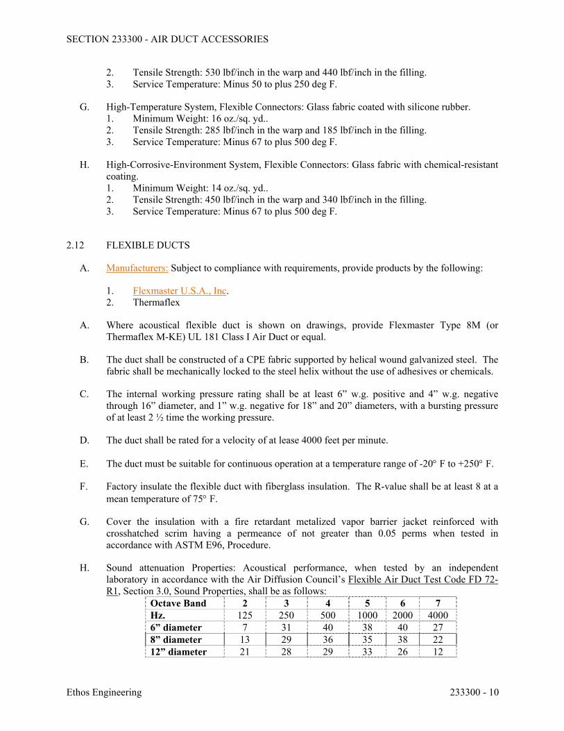
SECTION 233300 - AIR DUCT ACCESSORIES
Ethos Engineering 233300 - 10
2. Tensile Strength: 530 lbf/inch in the warp and 440 lbf/inch in the filling. 3. Service Temperature: Minus 50 to plus 250 deg F.
G. High-Temperature System, Flexible Connectors: Glass fabric coated with silicone rubber. 1. Minimum Weight: 16 oz./sq. yd.. 2. Tensile Strength: 285 lbf/inch in the warp and 185 lbf/inch in the filling. 3. Service Temperature: Minus 67 to plus 500 deg F.
H. High-Corrosive-Environment System, Flexible Connectors: Glass fabric with chemical-resistant coating. 1. Minimum Weight: 14 oz./sq. yd.. 2. Tensile Strength: 450 lbf/inch in the warp and 340 lbf/inch in the filling. 3. Service Temperature: Minus 67 to plus 500 deg F.
2.12 FLEXIBLE DUCTS
A. Manufacturers: Subject to compliance with requirements, provide products by the following:
1. Flexmaster U.S.A., Inc. 2. Thermaflex
A. Where acoustical flexible duct is shown on drawings, provide Flexmaster Type 8M (or Thermaflex M-KE) UL 181 Class I Air Duct or equal.
B. The duct shall be constructed of a CPE fabric supported by helical wound galvanized steel. The fabric shall be mechanically locked to the steel helix without the use of adhesives or chemicals.
C. The internal working pressure rating shall be at least 6” w.g. positive and 4” w.g. negative through 16” diameter, and 1” w.g. negative for 18” and 20” diameters, with a bursting pressure of at least 2 ½ time the working pressure.
D. The duct shall be rated for a velocity of at lease 4000 feet per minute.
E. The duct must be suitable for continuous operation at a temperature range of -20 F to +250 F.
F. Factory insulate the flexible duct with fiberglass insulation. The R-value shall be at least 8 at a mean temperature of 75 F.
G. Cover the insulation with a fire retardant metalized vapor barrier jacket reinforced with crosshatched scrim having a permeance of not greater than 0.05 perms when tested in accordance with ASTM E96, Procedure.
H. Sound attenuation Properties: Acoustical performance, when tested by an independent laboratory in accordance with the Air Diffusion Council’s Flexible Air Duct Test Code FD 72-R1, Section 3.0, Sound Properties, shall be as follows:
Octave Band 2 3 4 5 6 7 Hz. 125 250 500 1000 2000 4000 6” diameter 7 31 40 38 40 27 8” diameter 13 29 36 35 38 22 12” diameter 21 28 29 33 26 12
SECTION 233300 - AIR DUCT ACCESSORIES
Ethos Engineering 233300 - 11
I. Flexible Duct Connectors: 1. Clamps: Stainless-steel band with cadmium-plated hex screw to tighten band with a
worm-gear action in sizes 3 through 18 inches, to suit duct size.
2.13 DUCT ACCESSORY HARDWARE
A. Instrument Test Holes: Cast iron or cast aluminum to suit duct material, including screw cap and gasket. Size to allow insertion of pitot tube and other testing instruments and of length to suit duct-insulation thickness.
B. Adhesives: High strength, quick setting, neoprene based, waterproof, and resistant to gasoline and grease.
PART 3 - EXECUTION
3.1 INSTALLATION
A. Install duct accessories according to applicable details in SMACNA's "HVAC Duct Construction Standards - Metal and Flexible" for metal ducts and in NAIMA AH116, "Fibrous Glass Duct Construction Standards," for fibrous-glass ducts.
B. Install duct accessories of materials suited to duct materials; use galvanized-steel accessories in galvanized-steel and fibrous-glass ducts, stainless-steel accessories in stainless-steel ducts, and aluminum accessories in aluminum ducts.
C. Install backdraft dampers (control dampers for fans 2,000CFM and larger) at inlet of exhaust fans or exhaust ducts as close as possible to exhaust fan unless otherwise indicated.
D. Install volume dampers at points on supply, return, and exhaust systems where branches extend from larger ducts. Where dampers are installed in ducts having duct liner, install dampers with hat channels of same depth as liner, and terminate liner with nosing at hat channel. 1. Install steel volume dampers in steel ducts. 2. Install aluminum volume dampers in aluminum ducts.
E. Set dampers to fully open position before testing, adjusting, and balancing.
F. Install test holes at fan inlets and outlets and elsewhere as indicated.
G. Install fire and smoke dampers according to UL listing.
H. Install duct access doors on sides of ducts to allow for inspecting, adjusting, and maintaining accessories and equipment at the following locations: 1. On both sides of duct coils. 2. Upstream from duct filters. 3. At outdoor-air intakes and mixed-air plenums. 4. At drain pans and seals. 5. Downstream from manual volume dampers, control dampers, backdraft dampers, and
equipment.
SECTION 233300 - AIR DUCT ACCESSORIES
Ethos Engineering 233300 - 12
6. Adjacent to and close enough to fire or smoke dampers, to reset or reinstall fusible links. Access doors for access to fire or smoke dampers having fusible links shall be pressure relief access doors and shall be outward operation for access doors installed upstream from dampers and inward operation for access doors installed downstream from dampers.
7. At each change in direction and at maximum 50-foot spacing. 8. Upstream from turning vanes. 9. Upstream or downstream from duct silencers. 10. Control devices requiring inspection. 11. Elsewhere as indicated.
I. Install access doors with swing against duct static pressure.
J. Access Door Sizes: 1. One-Hand or Inspection Access: 8 by 5 inches. 2. Two-Hand Access: 12 by 6 inches. 3. Head and Hand Access: 18 by 10 inches. 4. Head and Shoulders Access: 21 by 14 inches. 5. Body Access: 25 by 14 inches. 6. Body plus Ladder Access: 25 by 17 inches.
K. Label access doors according to Section 230553 "Identification for HVAC Piping and Equipment" to indicate the purpose of access door.
L. Install flexible connectors to connect ducts to equipment.
M. For fans developing static pressures of 5-inch wg and more, cover flexible connectors with loaded vinyl sheet held in place with metal straps.
N. Connect terminal units to supply ducts directly, and for fan powered boxes with maximum 12-inch lengths of flexible duct. Do not use flexible ducts to change directions.
O. Connect flexible ducts to metal ducts with stainless steel draw bands.
P. Install duct test holes where required for testing and balancing purposes.
3.2 FIELD QUALITY CONTROL
A. Tests and Inspections: 1. Operate dampers to verify full range of movement. 2. Inspect locations of access doors and verify that purpose of access door can be
performed. 3. Operate fire, smoke, and combination fire and smoke dampers to verify full range of
movement and verify that proper heat-response device is installed. 4. Inspect turning vanes for proper and secure installation. 5. Operate remote damper operators to verify full range of movement of operator and
damper.
END OF SECTION 233300
SECTION 233423 - HVAC POWER VENTILATORS
Ethos Engineering 233423 - 1
PART 1 - GENERAL
1.1 RELATED DOCUMENTS
A. Drawings and general provisions of the Contract, including General and Supplementary Conditions and Division 01 Specification Sections, apply to this Section.
1.2 SUMMARY
A. Section Includes: 1. Centrifugal roof ventilators.
1.3 PERFORMANCE REQUIREMENTS
A. Project Altitude: Base fan-performance ratings on sea level.
B. Operating Limits: Classify according to AMCA 99.
C. Delegated Design: Design roof curbs to comply with wind performance requirements, including comprehensive engineering analysis by a qualified professional engineer, using performance requirements and design criteria indicated.
D. Wind-Restraint Performance rated for basic Wind Speed: Rated for project location.
1.4 ACTION SUBMITTALS
A. Product Data: For each type of product indicated. Include rated capacities, operating characteristics, and furnished specialties and accessories. Also include the following: 1. Certified fan performance curves with system operating conditions indicated. 2. Certified fan sound-power ratings. 3. Motor ratings and electrical characteristics, plus motor and electrical accessories. 4. Material thickness and finishes, including color charts. 5. Dampers, including housings, linkages, and operators. 6. Fan speed controllers. 7. Roof curbs.
B. Shop Drawings: Include plans, elevations, sections, details, and attachments to other work. 1. Detail equipment assemblies and indicate dimensions, weights, loads, required
clearances, method of field assembly, components, and location and size of each field connection.
2. Wiring Diagrams: For power, signal, and control wiring.
C. Delegated-Design Submittal: For unit hangars and supports indicated to comply with performance requirements and design criteria, including analysis data signed and sealed by the qualified professional engineer responsible for their preparation.
SECTION 233423 - HVAC POWER VENTILATORS
Ethos Engineering 233423 - 2
1. Vibration Isolation Base Details: Detail fabrication including anchorages and attachments to structure and to supported equipment. Include adjustable motor bases, rails, and frames for equipment mounting.
2. Design Calculations: Calculate requirements for selecting vibration isolators and for designing vibration isolation bases.
3. Wind Restraints and Certification.
D. Manufacturer Wind Loading Qualification Certification: Submit certification that specified equipment will withstand wind forces identified in "Performance Requirements" Article, Division 7 and in Division 23 Section "Vibration and Seismic Controls for HVAC Piping and Equipment."
1. Basis for Certification: Indicate whether withstand certification is based on actual test of assembled components or on calculations.
2. Dimensioned Outline Drawings of Equipment Unit: Identify center of wind force and locate and describe mounting and anchorage provisions.
3. Detailed description of equipment anchorage devices on which the certification is based and their installation requirements.
1.5 INFORMATIONAL SUBMITTALS
A. Coordination Drawings: Reflected ceiling plans and other details, drawn to scale, on which the following items are shown and coordinated with each other, using input from Installers of the items involved: 1. Framing and support members relative to duct penetrations. 2. Ceiling suspension assembly members. 3. Size and location of initial access modules for acoustical tile. 4. Ceiling-mounted items including light fixtures, diffusers, grilles, speakers, sprinklers,
access panels, and special moldings. 5. Roof framing and support members relative to duct penetrations.
B. Certified Compliance Statement and shop drawings from a licensed PE for IBC and TDI. 1. Sealed shop drawings showing installation instructions and attachment of equipment to
curb, and curb to structure. Include quantity and type of restraining brackets/clips, screws, spacing, etc.
2. As a separate attachment provide sealed IBC and TDI compliant calculations for curbs and attachment.
C. Field quality-control reports.
1.6 CLOSEOUT SUBMITTALS
A. Operation and Maintenance Data: For power ventilators to include in emergency, operation, and maintenance manuals.
SECTION 233423 - HVAC POWER VENTILATORS
Ethos Engineering 233423 - 3
1.7 MAINTENANCE MATERIAL SUBMITTALS
A. Furnish extra materials that match products installed and that are packaged with protective covering for storage and identified with labels describing contents. 1. Belts: One set for each belt-driven unit.
1.8 QUALITY ASSURANCE
A. Electrical Components, Devices, and Accessories: Listed and labeled as defined in NFPA 70, by a qualified testing agency, and marked for intended location and application.
B. AMCA Compliance: Fans shall have AMCA-Certified performance ratings and shall bear the AMCA-Certified Ratings Seal.
C. UL Standards: Power ventilators shall comply with UL 705. Power ventilators for use for restaurant kitchen exhaust shall also comply with UL 762.
D. International Building Code and TDI Compliance: Licensed Professional Engineer shall certify that the listed items are designed for and will withstand wind speed for the location of the project, per the relevant edition of International Building Code, ASCE Std 7, Texas Department of Insurance requirements. 1. Equipment curb/attachment for exterior and roof mounted equipment such as fans. 2. Attachment of equipment to curb/pad. 3. Attachment of curb/pad to building structure.
1.9 COORDINATION
A. Coordinate size and location of structural-steel support members.
B. Coordinate installation of roof curbs, equipment supports, and roof penetrations. These items are specified in Division 7 Section "Roof Accessories."
1.10 WARRANTY
A. General Warranty: The special warranty specified in this Article shall not deprive the Owner of other rights the Owner may have under other provisions of the Contract Documents and shall be in addition to, and run concurrent with, other warranties made by the Contractor under requirements of the Contract Documents.
B. Special Warranty: A written warranty, executed by Contractor and signed by manufacturer, agreeing to replace components that fail in materials and workmanship within the specified warranty period, provided manufacturer's written instructions for installation, operation, and maintenance have been followed.
1. Warranty Period: One (1) year parts and labor for fan and motor, including all components, from date of Substantial Completion.
SECTION 233423 - HVAC POWER VENTILATORS
Ethos Engineering 233423 - 4
1.11 EXTRA MATERIALS
A. Furnish extra materials described below that match products installed and that are packaged with protective covering for storage and identified with labels describing contents. 1. Belts: One set for each belt-driven unit.
PART 2 - PRODUCTS
2.1 MANUFACTURERS
A. HVAC Power Ventilators: Subject to compliance with requirements, provide products by one of the following: 1. Loren Cook Company. 2. Greenheck Fan Corp. 3. New York Blower Company (The). 4. Penn Ventilation.
2.2 CENTRIFUGAL ROOF VENTILATORS
A. Description: Direct- or belt-driven centrifugal fans consisting of housing, wheel, fan shaft, bearings, motor and disconnect switch, drive assembly, curb base, and accessories.
B. Housing: Removable, spun-aluminum, dome top and outlet baffle; square, one-piece, aluminum base with venturi inlet cone. 1. Upblast Units (where indicated): Provide spun-aluminum discharge baffle to direct
discharge air upward, with rain and snow drains and grease collector. 2. Hinged Subbase: Galvanized-steel hinged arrangement permitting service and
maintenance.
C. Fan Wheels: Aluminum hub and wheel with backward-inclined blades.
D. Belt-Driven Drive Assembly: Resiliently mounted to housing, with the following features: 1. Fan Shaft: Turned, ground, and polished steel; keyed to wheel hub. 2. Shaft Bearings: Permanently lubricated, permanently sealed, self-aligning ball bearings. 3. Pulleys: Cast-iron, adjustable-pitch motor pulley. 4. Fan and motor isolated from exhaust airstream.
E. Accessories: 1. Variable-Speed Controller: Solid-state control to reduce speed from 100 to less than 50
percent. 2. Disconnect Switch: Nonfusible type, with thermal-overload protection mounted inside
fan housing, factory wired through an internal aluminum conduit. 3. Bird Screens: Removable, 1/2-inch mesh, stainless steel. 4. Dampers: Counterbalanced, parallel-blade, backdraft dampers mounted in curb base;
factory set to close when fan stops. 5. Motorized Dampers for airflow 2000CFM and larger: Parallel-blade dampers mounted in
curb base with electric actuator; wired to close when fan stops. 6. Explosion proof motors and spark resistant fans where indicated.
SECTION 233423 - HVAC POWER VENTILATORS
Ethos Engineering 233423 - 5
F. Roof Curbs: Galvanized steel; mitered and welded corners; 1-1/2-inch- thick, rigid, fiberglass insulation adhered to inside walls; and 1-1/2-inch wood nailer. Size as required to suit roof opening and fan base.
2.3 ROOF MOUNTED EQUIPMENT
A. Wind Restraints: Metal brackets compatible with the curb and casing, painted to match RTU, used to anchor unit to the curb, and designed for loads at Project site.
B. Ecoat or Lorenized coating on all exposed fans, vent hoods and fan cabinets
2.4 MOTORS
A. Comply with NEMA designation, temperature rating, service factor, enclosure type, and efficiency requirements for motors specified in Section 230513 "Common Motor Requirements for HVAC Equipment." 1. Motor Sizes: Minimum size as indicated. If not indicated, large enough so driven load
will not require motor to operate in service factor range above 1.0.
B. Enclosure Type: Totally enclosed, fan cooled.
2.5 SOURCE QUALITY CONTROL
A. Certify sound-power level ratings according to AMCA 301, "Methods for Calculating Fan Sound Ratings from Laboratory Test Data." Factory test fans according to AMCA 300, "Reverberant Room Method for Sound Testing of Fans." Label fans with the AMCA-Certified Ratings Seal.
B. Certify fan performance ratings, including flow rate, pressure, power, air density, speed of rotation, and efficiency by factory tests according to AMCA 210, "Laboratory Methods of Testing Fans for Aerodynamic Performance Rating." Label fans with the AMCA-Certified Ratings Seal.
PART 3 - EXECUTION
3.1 INSTALLATION
A. Install power ventilators level and plumb.
B. Secure roof-mounting fans to roof curbs with cadmium-plated hardware. Refer to Division 7 Section "Roof Accessories" for installation of roof curbs.
C. Ceiling Units: Suspend units from structure; use steel wire or metal straps.
D. Support suspended units from structure using threaded steel rods and spring hangers having a static deflection of 1 inch. Vibration-control devices are specified in Section 230548.13 "Vibration Controls for HVAC."
SECTION 233423 - HVAC POWER VENTILATORS
Ethos Engineering 233423 - 6
E. Install units with clearances for service and maintenance.
F. Label units according to requirements specified in Section 230553 "Identification for HVAC Piping and Equipment."
3.2 CONNECTIONS
A. Drawings indicate general arrangement of ducts and duct accessories. Make final duct connections with flexible connectors. Flexible connectors are specified in Section 233300 "Air Duct Accessories."
B. Install ducts adjacent to power ventilators to allow service and maintenance.
C. Ground equipment according to Section 260526 "Grounding and Bonding for Electrical Systems."
D. Connect wiring according to Section 260519 "Low-Voltage Electrical Power Conductors and Cables."
3.3 FIELD QUALITY CONTROL
A. Perform tests and inspections. 1. Verify that shipping, blocking, and bracing are removed. 2. Verify that unit is secure on mountings and supporting devices and that connections to
ducts and electrical components are complete. Verify that proper thermal-overload protection is installed in motors, starters, and disconnect switches.
3. Verify that cleaning and adjusting are complete. 4. Disconnect fan drive from motor, verify proper motor rotation direction, and verify fan
wheel free rotation and smooth bearing operation. Reconnect fan drive system, align and adjust belts, and install belt guards.
5. Adjust belt tension. 6. Adjust damper linkages for proper damper operation. 7. Verify lubrication for bearings and other moving parts. 8. Verify that manual and automatic volume control and fire and smoke dampers in
connected ductwork systems are in fully open position. 9. Disable automatic temperature-control operators, energize motor and adjust fan to
indicated rpm, and measure and record motor voltage and amperage. 10. Shut unit down and reconnect automatic temperature-control operators. 11. Remove and replace malfunctioning units and retest as specified above.
B. Starting Procedures: 1. Energize motor and adjust fan to indicated rpm. 2. Measure and record motor voltage and amperage.
C. Operational Test: After electrical circuitry has been energized, start units to confirm proper motor rotation and unit operation. Remove malfunctioning units, replace with new units, and retest.
SECTION 233423 - HVAC POWER VENTILATORS
Ethos Engineering 233423 - 7
D. Test and adjust controls and safeties. Replace damaged and malfunctioning controls and equipment.
3.4 ADJUSTING
A. Adjust damper linkages for proper damper operation.
B. Adjust belt tension.
C. Comply with requirements in Section 230593 "Testing, Adjusting, and Balancing for HVAC" for testing, adjusting, and balancing procedures.
D. Replace fan and motor pulleys as required to achieve design airflow.
E. Lubricate bearings.
3.5 DEMONSTRATION
A. Train Owner's maintenance personnel to adjust, operate, and maintain power ventilators. 1. Train Owner's maintenance personnel on procedures and schedules for starting and
stopping, troubleshooting, servicing, and maintaining equipment and schedules. 2. Review data in maintenance manuals. Refer to Division 1 Section "Operation and
Maintenance Data." 3. Schedule training with Owner, through Architect, with at least seven days' advance
notice.
END OF SECTION 233423
SECTION 233713 - DIFFUSERS, REGISTERS, AND GRILLES
Ethos Engineering 233713 - 1
PART 1 - GENERAL
1.1 RELATED DOCUMENTS
A. Drawings and general provisions of the Contract, including General and Supplementary Conditions and Division 01 Specification Sections, apply to this Section.
1.2 SUMMARY
A. Section Includes grilles, registers, diffusers, and other air devices
B. Related Sections:
1. Section 089116 "Operable Wall Louvers" and Section 089119 "Fixed Louvers" for fixed and adjustable louvers and wall vents, whether or not they are connected to ducts.
2. Section 233300 "Air Duct Accessories" for fire and smoke dampers and volume-control dampers not integral to diffusers, registers, and grilles.
1.3 ACTION SUBMITTALS
A. Product Data: For each type of product indicated, include the following:
1. Data Sheet: Indicate materials of construction, finish, and mounting details; and performance data including throw and drop, static-pressure drop, and noise ratings.
2. Diffuser, Register, and Grille Schedule: Indicate drawing designation, room location, quantity, model number, size, and accessories furnished.
B. Samples for Initial Selection: For diffusers, registers, and grilles with factory-applied color finishes.
1.4 INFORMATIONAL SUBMITTALS
A. Coordination Drawings: Reflected ceiling plans, drawn to scale, on which the following items are shown and coordinated with each other, using input from Installers of the items involved:
1. Ceiling suspension assembly members. 2. Method of attaching hangers to building structure. 3. Size and location of initial access modules for acoustical tile. 4. Ceiling-mounted items including lighting fixtures, diffusers, grilles, speakers, sprinklers,
access panels, and special moldings. 5. Duct access panels.
B. Source quality-control reports.
SECTION 233713 - DIFFUSERS, REGISTERS, AND GRILLES
Ethos Engineering 233713 - 2
PART 2 - PRODUCTS
2.1 MANUFACTURERS
A. Subject to compliance with requirements, provide products by one of the manufacturers specified: 1. Price Industries. 2. Titus.
2.2 AIR DEVICES
A. Rectangular and Square Ceiling Grilles, Registers, Diffusers: See schedules for material, finish, size, pattern, damper type, and accessories.
B. Fire rated air devices: Plans indicate a “fire damper” designation on diffusers that need a fire rated air device. Coordinate with plans.
2.3 INSULATION
A. All cold surfaces that are susceptible to condensation shall be insulated.
B. Insulation may be provided by manufacturer or by installing Contractor. Coordinate with installing Contractor.
2.4 SOURCE QUALITY CONTROL
A. Verification of Performance: Rate diffusers, registers, and grilles according to ASHRAE 70, "Method of Testing for Rating the Performance of Air Outlets and Inlets."
PART 3 - EXECUTION
3.1 EXAMINATION
A. Examine areas where diffusers, registers, and grilles are to be installed for compliance with requirements for installation tolerances and other conditions affecting performance of equipment.
B. Proceed with installation only after unsatisfactory conditions have been corrected.
3.2 INSTALLATION
A. Install diffusers, registers, and grilles level and plumb.
B. Ceiling-Mounted Outlets and Inlets: Drawings indicate general arrangement of ducts, fittings, and accessories. Air outlet and inlet locations have been indicated to achieve design
SECTION 233713 - DIFFUSERS, REGISTERS, AND GRILLES
Ethos Engineering 233713 - 3
requirements for air volume, noise criteria, airflow pattern, throw, and pressure drop. Make final locations where indicated, as much as practical. For units installed in lay-in ceiling panels, locate units in the center of panel. Where architectural features or other items conflict with installation, notify Architect for a determination of final location.
C. Install diffusers, registers, and grilles with airtight connections to ducts and to allow service and maintenance of dampers, air extractors, and fire dampers.
3.3 ADJUSTING
A. After installation, adjust diffusers, registers, and grilles to air patterns indicated, or as directed, before starting air balancing.
END OF SECTION 233713
SECTION 238126 - SPLIT-SYSTEM AIR-CONDITIONERS
Ethos Engineering 238126 - 1
PART 1 - GENERAL
1.1 RELATED DOCUMENTS
A. Drawings and general provisions of the Contract, including General and Supplementary Conditions and Division 01 Specification Sections, apply to this Section.
1.2 SUMMARY
A. Section includes split-system air-conditioning units consisting of separate evaporator-fan and compressor-condenser components.
1.3 SUBMITTALS
A. Product Data: Include rated capacities, operating characteristics, and furnished specialties and accessories. Include performance data in terms of capacities, outlet velocities, static pressures, sound power characteristics, motor requirements, and electrical characteristics.
B. Shop Drawings: Include plans, elevations, sections, details, and attachments to other work.
1. Detail equipment assemblies and indicate dimensions, weights, loads, required clearances, method of field assembly, components, and location and size of each field connection.
2. Wiring Diagrams: For power, signal, and control wiring.
C. Field quality-control reports.
D. Operation and Maintenance Data: For split-system air-conditioning units to include in emergency, operation, and maintenance manuals.
E. Warranty: Sample of special warranty.
1.4 QUALITY ASSURANCE
A. Electrical Components, Devices, and Accessories: Listed and labeled as defined in NFPA 70, by a qualified testing agency, and marked for intended location and application.
B. ASHRAE Compliance:
1. Fabricate and label refrigeration system to comply with ASHRAE 15, "Safety Standard for Refrigeration Systems."
2. ASHRAE Compliance: Applicable requirements in ASHRAE 62.1-2004, Section 4 - "Outdoor Air Quality," Section 5 - "Systems and Equipment," Section 6 - " Procedures," and Section 7 - "Construction and System Start-Up."
C. ASHRAE/IESNA Compliance: Applicable requirements in ASHRAE/IESNA 90.1-2004.
SECTION 238126 - SPLIT-SYSTEM AIR-CONDITIONERS
Ethos Engineering 238126 - 2
1.5 COORDINATION
A. Coordinate sizes and locations of concrete bases with actual equipment provided. Cast anchor-bolt inserts into bases. Concrete, reinforcement, and formwork are specified in Division 03 Section "Cast-in-Place Concrete."
1.6 WARRANTY
A. Special Warranty: Manufacturer's standard form in which manufacturer agrees to repair or replace components of split-system air-conditioning units that fail in materials or workmanship within specified warranty period. Warranty period to commence from the date of equipment start-up.
1. Warranty Period:
a. For Compressor: Five year(s) from date of Substantial Completion. b. For Parts and Labor: One year(s) from date of Substantial Completion.
1.7 EXTRA MATERIALS
A. Furnish extra materials that match products installed and that are packaged with protective covering for storage and identified with labels describing contents.
1. Filters: One set for each air-handling unit. 2. Fan Belts: One set for each air-handling unit fan.
PART 2 - PRODUCTS
2.1 MANUFACTURERS
A. Manufacturers: Subject to compliance with requirements, provide products by one of the following:
1. Trane. 2. Carrier Corporation; Home Comfort and HVAC Building & Industrial Systems. 3. Lennox International Inc. 4. YORK; a Johnson Controls company.
2.2 INDOOR UNITS 5 TONS OR LESS
A. Vertical, Evaporator-Fan Components: An assembly including cabinet, filter, chassis, coil, drain pan, fan, and motor in blow-through configuration with direct-expansion heat pump cooling coil, and electric heating coil where noted.
B. Cabinet: Covers and access panels shall be manufactured of 20 gauge pre- painted, galvanized sheet metal. Cabinet walls shall have insulated panels, fabricated to allow removal for access to internal parts and components. Units shall be designed and equipped for installation indoors.
SECTION 238126 - SPLIT-SYSTEM AIR-CONDITIONERS
Ethos Engineering 238126 - 3
C. Chassis: Unit structural members shall be manufactured of 16 gauge pre-painted, galvanized sheet metal. Removable panels for servicing, and insulation on back of panel.
1. Insulation: Standard insulation or minimum 1”, whichever is greater.
D. Refrigerant Coil: Copper tube, with mechanically bonded aluminum fins, complying with ARI 210/240, and with thermal-expansion valve.
E. Reheat Coil: If scheduled, unit shall include a hot gas reheat coil with a modulating reheat control valve and an electronic controller. The valve position shall be controlled to provide a specific supply air temperature setpoint that is set on the control board or sent to the control board by a remote 0-10 Vdc signal.
F. Electric Coil: If scheduled, helical, nickel-chrome, resistance-wire heating elements with refractory ceramic support bushings; automatic-reset thermal cutout; built-in magnetic contactors; manual-reset thermal cutout; airflow proving device; and one-time fuses in terminal box for over-current protection.
G. Fan Motors: Comply with requirements in Division 23 Section "Common Motor Requirements for HVAC Equipment." 1. Special Motor Features: Multi-tapped, multi-speed with internal thermal protection and
permanent lubrication. 2. Comply with NEMA designation, temperature rating, service factor, enclosure type, and
efficiency requirements specified in Division 23 Section "Common Motor Requirements for HVAC Equipment."
3. Enclosure Type: Totally enclosed, fan cooled. 4. NEMA Premium (TM) efficient motors as defined in NEMA MG 1. 5. Controllers, Electrical Devices, and Wiring: Comply with requirements for electrical
devices and connections specified in Division 26 Sections. 6. Mount unit-mounted disconnect switches on unit.
H. Airstream Surfaces: Surfaces in contact with the airstream shall comply with requirements in ASHRAE 62.1-2004.
I. Condensate Drain Pans: 1. Fabricated with slope in at least two planes to collect condensate from cooling coils
(including coil piping connections, coil headers, and return bends) and humidifiers, and to direct water toward drain connection.
1) Length: Extend drain pan downstream from leaving face to comply with ASHRAE 62.1-2004.
2) Depth: A minimum of 1 inch deep.
b. Stainless-steel sheet or non-corrosive plastic, insulated. c. Drain Connection: Located at lowest point of pan and sized to prevent overflow.
Terminate with threaded nipple on one end of pan.
2. Air Filtration Section:
a. General Requirements for Air Filtration Section:
SECTION 238126 - SPLIT-SYSTEM AIR-CONDITIONERS
Ethos Engineering 238126 - 4
1) Comply with NFPA 90A. 2) Minimum Arrestance: According to ASHRAE 52.1 and MERV according
to ASHRAE 52.2. 3) Filter-Holding Frames: Arranged for flat or angular orientation, with access
doors on both sides of unit. Filters shall be removable from one side or lifted out from access plenum.
b. Filters:
1) Factory-fabricated, viscous-coated, flat-panel type. 2) Thickness: 2 inches. 3) Merv according to ASHRAE 52.2: 8. 4) Media: Interlaced glass fibers sprayed with nonflammable adhesive and
antimicrobial agent. 5) Frame: Galvanized steel, with metal grid on outlet side, steel rod grid on
inlet side, and hinged; with pull and retaining handles.
2.3 OUTDOOR UNITS (5 TONS OR LESS)
A. Air-Cooled, Compressor-Condenser Components:
1. Casing: Corrosion free pre-painted steel cabinet, finished with baked enamel, with removable panels for access to controls, weep holes for water drainage, and mounting holes in base. Provide brass service valves, fittings, and gage ports on exterior of casing.
2. Compressor: Hermetically sealed with crankcase heater and mounted on vibration isolation device. Compressor motor shall have thermal- and current-sensitive overload devices, start capacitor, relay, and contactor.
a. Compressor Type: Scroll, mounted on rubber mounts for vibration isolation. b. Two-stage (where scheduled) compressor motor with manual-reset high-pressure
switch and automatic-reset low-pressure switch. c. Refrigerant Charge: R-407C or R-410A. d. Refrigerant Coil: Copper tube, with mechanically bonded aluminum fins and
liquid subcooler. Comply with ARI 210/240. e. Internal excessive current and temperature protection.
3. Fan: Aluminum-propeller type, directly connected to motor. 4. Motor: Permanently lubricated, with integral thermal-overload protection.
2.4 CONTROLS
A. Programmable thermidistat to control compressor and evaporator fan, with the following features:
1. Compressor time delay. 2. 24-hour time control of system stop and start. 3. Liquid-crystal display indicating temperature and RH, set-point temperature and RH,
time setting, operating mode, and fan speed.
SECTION 238126 - SPLIT-SYSTEM AIR-CONDITIONERS
Ethos Engineering 238126 - 5
2.5 ACCESSORIES
A. Other: 1. Direct driven ECM fan motor, and with built in dehumidification sequence option for
indoor units. 2. Low Ambient Controller: Cycles condenser fan to permit operation down to 35 deg F
with time-delay relay to bypass low-pressure switch. 3. Package with refrigerant circuit suction and discharge gauges, and service valves. 4. Automatic-reset timer to prevent rapid cycling of compressor. 5. Site glass, filter-dryer. 6. High-Pressure Switch: Automatic-reset switch cycles compressor off on high refrigerant
pressure. 7. Low-Pressure Switch: Automatic-reset switch cycles compressor off on low refrigerant
pressure. 8. Thermostatic expansion valve to match with existing Evaporator Coil, if existing is
incompatible. 9. Time-Delay Relay: Continues operation of evaporator fan after compressor shuts off. 10. Evaporator defrost controller. 11. Liquid line solenoid valves, electric unloaders, factory/field installed accumulators to
accomplish stages of unloading. 12. See drawing schedules.
B. Unit Casing: Galvanized steel, finished with paint finish capable of withstanding at least 1000 hours when tested in salt spray atmosphere (ASTM B 117- 95 test procedure); with removable panels for access to controls, weep holes for water drainage, and mounting holes in base. Mount service valves, fittings, and gage ports on exterior of casing. 1. Condenser coil hail guard to protect coil from physical damage. 2. Condenser coil coating: epoxy coat or Energy Guard
PART 3 - EXECUTION
3.1 INSTALLATION
A. Install units level and plumb.
B. Install evaporator-fan components using manufacturer's standard mounting devices securely fastened to building structure.
C. Install ground-mounted, compressor-condenser components on 4-inch- thick, reinforced concrete base that is 4 inches larger, on each side, than unit. Concrete, reinforcement, and formwork are specified in Division 03 Section "Cast-in-Place Concrete." Coordinate anchor installation with concrete base.
D. Install and connect refrigerant tubing to component's quick-connect fittings. Install tubing to allow access to unit.
E. Provide auxiliary drain pans with float switches to disable fans. Provide drain piping with stop valves from pans to floor drains.
SECTION 238126 - SPLIT-SYSTEM AIR-CONDITIONERS
Ethos Engineering 238126 - 6
3.2 CONNECTIONS
A. Piping installation requirements are specified in other Division 23 Sections. Drawings indicate general arrangement of piping, fittings, and specialties.
B. Where piping is installed adjacent to unit, allow space for service and maintenance of unit.
C. Duct Connections: Duct installation requirements are specified in Division 15 Section "Metal Ducts." Drawings indicate the general arrangement of ducts. Connect supply and return ducts to split-system air-conditioning units with flexible duct connectors. Flexible duct connectors are specified in Division 15 Section "Duct Accessories."
D. Ground equipment according to Division 16 Section "Grounding and Bonding."
E. Electrical Connections: Comply with requirements in Division 16 Sections for power wiring, switches, and motor controls.
3.3 FIELD QUALITY CONTROL
A. Manufacturer's Field Service: Engage a factory-authorized service representative to inspect, test, and adjust components, assemblies, and equipment installations, including connections.
B. Tests and Inspections:
1. Leak Test: After installation, charge system and test for leaks. Repair leaks and retest until no leaks exist.
2. Operational Test: After electrical circuitry has been energized, start units to confirm proper motor rotation and unit operation.
3. Test and adjust controls and safeties. Replace damaged and malfunctioning controls and equipment.
C. Remove and replace malfunctioning units and retest as specified above.
D. Prepare test and inspection reports.
3.4 STARTUP SERVICE
A. Engage a factory-authorized service representative to perform startup service.
B. Verify that air-conditioning units are installed and connected according to manufacturer's written instructions and the Contract Documents. 1. Verify that shipping, blocking, and bracing are removed. 2. Verify that unit is secure on mountings and supporting devices and that connections to
piping, ducts, and electrical systems are complete. Verify that proper thermal-overload protection is installed in motors, controllers, and switches.
3. Verify proper motor rotation direction, free fan wheel rotation, and smooth bearing operations. Reconnect fan drive system, align belts, and install belt guards.
4. Verify that bearings, pulleys, belts, and other moving parts are lubricated with factory-recommended lubricants.
SECTION 238126 - SPLIT-SYSTEM AIR-CONDITIONERS
Ethos Engineering 238126 - 7
5. Verify that outdoor- and return-air mixing dampers open and close, and maintain minimum outdoor-air setting.
6. Comb coil fins for parallel orientation. 7. Verify that proper thermal-overload protection is installed for electric coils. 8. Install new, clean filters. 9. Verify that manual and automatic volume control and fire and smoke dampers in
connected 10. Energize motor; verify proper operation of motor, drive system, and fan wheel. Adjust
fan to indicated rpm. Replace fan and motor pulleys as required to achieve design conditions.
11. Measure and record motor electrical values for voltage and amperage.
C. Verify that electrical wiring installation complies with manufacturer's submittal and installation requirements in Division 26 Sections.
D. Complete installation and startup checks according to manufacturer's written instructions.
E. After startup service and performance test, change filters.
F. Manually operate dampers from fully closed to fully open position and record fan performance.
3.5 DEMONSTRATION
A. Engage a factory-authorized service representative to train Owner's maintenance personnel to adjust, operate, and maintain units.
END OF SECTION 238126
SECTION 260010 - SUMMARY OF ELECTRICAL WORK
Ethos Engineering 260010 - 1
PART 1 - GENERAL 1.1 RELATED DOCUMENTS
A. Drawings and general provisions of the Contract, including General and Supplementary
Conditions, Division 1 Specification Sections and other Division 26 Specification Sections, apply to this Section.
1.2 WORK COVERED BY CONTRACT DOCUMENTS
A. The following Summary of Work is intended as an aid to achieve an understanding of the
various elements of work included in the project, as is not intended to be all-inclusive. Detailed descriptions of work and requirements are given in drawings and specifications.
B. Scope of Work:
1. General: The Project consists of an existing single-story building, approximately 3,140 sq. ft.
2. Electrical: Provide all materials and labor associated with complete operational electrical distribution system. Major items of work include, but are not limited to:
(a) Power systems: Provide connections for HVAC, and plumbing equipment. 1.3 ALLOWANCES
A. Electrical: See Division 1 for electrical allowances.
1.4 COORDINATION
A. All electrical work shall be done under sub-contract to a General Contractor, who ultimately responsible for the entire project. Electrical Contractor shall coordinate all work through General Contractor, even in areas where only electrical work is to take place.
B. All questions, requests for information, submittals, and correspondence from the Electrical Contractor shall be submitted via the General Contractor, who will forward to the Architect, who will then forward to the Engineer.
C. Electrical Contractor shall not make any changes to design without written authorization from the Engineer. If changes are requested by the Owner, Architect, General Contractor, Suppliers, Manufacturers, or any others, Contractor should issue a written RFI for response by the Engineer.
D. Electrical Contractor shall issue seven (7) days written notice prior to any activities that require the presence of the Engineer at the job-site. This applies to all inspections required by specifications, and particularly to those where work will be covered (underground raceways, electrical raceways above ceiling).
E. Cooperate fully with other contractors so that work under those contracts may be carried out smoothly, without interfering with or delaying work under this Contract.
SECTION 260010 - SUMMARY OF ELECTRICAL WORK
Ethos Engineering 260010 - 2
F. Fully coordinate with Mechanical Contractor for providing power to HVAC systems and plumbing equipment.
G. Fully coordinate with Owner for providing power to concession stand equipment.
H. Issue written notification of the following tasks and allow five (5) days for Engineer to respond and schedule an inspection as required:
1. Upon completion of underground raceways installation and prior to covering up. 2. Upon completion of installing all raceways, labeling all j-boxes and prior to suspended
ceiling installation. 3. Upon completion of pulling all wiring, making all terminations, labeling and color-coding
wires at the panelboards/switchboards and prior to installing their covers. 4. When ready to request manufacturer’s start-up of each piece of equipment. 5. When ready for Substantial Completion Inspection. 6. When ready for Final Inspection.
Failure to issue written notification may result in work having to be redone to allow for proper
inspection. It is this contractor’s responsibility to make sure Engineer receives notification. 1.5 UTILITIES
1. Coordinate with power, water, telephone, cable and gas utilities to locate all utilities prior to digging in any area.
2. Obtain any approvals required from utilities to relocate utilities. 3. Cost of relocating or bypassing utilities indicated on drawings shall be included in Base
Bid. 4. Coordinate with utility for electrical service. Base bid shall include all costs associated
with service connection, including permit fees.
1.6 CONTRACTOR USE OF PREMISES A. Use of the Site: Limit use of the premises to work in areas indicated. Confine operations to
areas within contract limits indicated. Do not disturb portions of the site beyond the areas in which the Work is indicated. 1. Owner Occupancy: Allow for Owner occupancy and use by the public. 2. Driveways and Entrances: Keep driveways and entrances serving the premises, clear
and available to the Owner, the Owner's employees, and emergency vehicles at all time. Do not use these areas for parking or storage of materials. Schedule deliveries to minimize space and time requirements for storage of materials and equipment on-site.
B. Site Safety: Take every precaution to ensure the site does not present a threat to the safety of
occupants and/or workers. Minimal safety requirements include, but are not limited to the following: 1. Temporary fencing around construction areas. 2. Yellow caution tape and construction barricades along open trenches during the day.
Trenches shall be covered at night and warning lights provided on construction barricades.
3. Temporary fencing around equipment while site work is in progress.
SECTION 260010 - SUMMARY OF ELECTRICAL WORK
Ethos Engineering 260010 - 3
C. Work shall take place with minimal disruption to Owner's operations in areas surrounding the job site.
1.7 SUBMITTALS -Special Requirements
A. Manufacturer's standard dimensioned drawings, performance and product data shall be edited to delete reference to equipment, features, or information, which is not applicable to the equipment being supplied for this project. Including Bill or List of Materials.
B. Faxes and copies of faxes are not acceptable. C. Electrical Submittals shall be submitted electronically. Please organize the files in packages as
follows (PDF format). Files would need to be properly identified (cover letter, stamped, etc.) from the general contractor.
1. Miscellaneous Electrical
a. 260519 Low-Voltage Electrical Power Conductors and Cables b. 260526 Grounding and Bonding for Electrical Systems c. 260529 Hangers and Supports for Electrical Systems d. 260533 Raceways and Boxes for Electrical Systems e. 260544 Sleeves and Sleeve Seals for Electrical Raceways and Cabling f. 260553 Identification for Electrical Systems g. 262726 Wiring Devices h. 260850 Hand Dryer
2. Electrical Gear a. 262416 Panelboards
Light Fixtures a. 265116 Interior Lighting b. 265621 Exterior Lighting
3. Special Systems: a. 267240 Intrusion Detection System
4. Electrical Commissioning a. 260800 Commissioning for Electrical Systems
E. Individual submittals shall not be reviewed until a complete package is received. F. Allow two weeks for initial submittal review by Engineer, from the day it is received at the
Engineer's office. G. Allow one week for review of resubmittals by Engineer. H. All submittal review comments shall be forwarded by Engineer to Architect, who will then
distribute as per Division 1.
1.8 SCHEDULE OF VALUES -Special Requirements
SECTION 260010 - SUMMARY OF ELECTRICAL WORK
Ethos Engineering 260010 - 4
A. Electrical Contractor shall submit a Schedule of Values reflecting the total value of Electrical Work in the Contract, and broken down into the following items as a minimum, with a line item for Materials/Equipment and another for Labor.
ELECTRICAL 1. Electrical gear. 4. Interior raceways including wiring. 2. Light fixtures, Wiring devices and Hand Dryers 3. Commissioning 4. Allowances. 5. Miscellaneous. 6. Administrative and project management.
1.9 CODE COMPLIANCE:
The design for this project is based on:
1. Occupational Safety and Health Act (OSHA) 2. National Electric Code (NEC) 3. National Fire Code 4. International Building Code 5. UL 916 6. Local ordinances
END OF SECTION 260010
SECTION 260519 - LOW-VOLTAGE ELECTRICAL POWER CONDUCTORS AND CABLES
Ethos Engineering 260519 - 1
PART 1 - GENERAL
1.1 RELATED DOCUMENTS
A. Drawings and general provisions of the Contract, including General and Supplementary Conditions and Division 01 Specification Sections, apply to this Section.
1.2 SUMMARY
A. Section Includes:
1. Building wires and cables rated 600 V and less. 2. Connectors, splices, and terminations rated 600 V and less.
1.3 DEFINITIONS
A. VFC: Variable frequency controller.
1.4 ACTION SUBMITTALS
A. Product Data: For each type of product.
1.5 INFORMATIONAL SUBMITTALS
A. Qualification Data: For testing agency.
B. Field quality-control reports.
1.6 QUALITY ASSURANCE
A. Testing Agency Qualifications: Member Company of NETA or an NRTL.
PART 2 - PRODUCTS
2.1 CONDUCTORS AND CABLES
A. Manufacturer:
1. Senator Wire & Cable Company. 2. Southwire Company. 3. Encore Wire
SECTION 260519 - LOW-VOLTAGE ELECTRICAL POWER CONDUCTORS AND CABLES
Ethos Engineering 260519 - 2
B. Copper Conductors: Comply with NEMA WC 70/ICEA S-95-658.
C. Conductor Insulation: Comply with NEMA WC 70/ICEA S-95-658 for Type THHN/THWN-2, Type XHHW-2 and Type SO.
D. Multiconductor Cable: Comply with NEMA WC 70/ICEA S-95-658 for metal-clad cable, Type MC and Type SO with ground wire.
E. VFC Cable:
1. Comply with UL 1277, UL 1685, and NFPA 70 for Type TC-ER cable. 2. Type TC-ER with oversized cross-linked polyethylene insulation, spiral-wrapped foil
plus 85 percent coverage braided shields and insulated full-size ground wire or dual spirally wrapped copper tape shields and three bare symmetrically applied ground wires, and sunlight- and oil-resistant outer PVC jacket.
3. Comply with UL requirements for cables in [Classes I and II, Division 2 hazardous location] applications.
2.2 CONNECTORS AND SPLICES
A. Manufacturers:
1. AFC Cable Systems, Inc. 2. AMP Incorporated/Tyco International. 3. Hubbell/Anderson. 4. O-Z/Gedney; EGS Electrical Group LLC. 5. 3M Company; Electrical Products Division.
B. Description: Factory-fabricated connectors and splices of size, ampacity rating, material, type, and class for application and service indicated.
2.3 SYSTEM DESCRIPTION
A. Electrical Components, Devices, and Accessories: Listed and labeled as defined in NFPA 70, by a qualified testing agency, and marked for intended location and application.
B. Comply with NFPA 70.
PART 3 - EXECUTION
3.1 CONDUCTOR MATERIAL APPLICATIONS
A. Feeders: Copper. Solid for No. 10 AWG and smaller; stranded for No. 8 AWG and larger.
B. Branch Circuits: Copper. Solid for No. 10 AWG and smaller; stranded for No. 8 AWG and larger, except VFC cable, which shall be extra flexible stranded.
SECTION 260519 - LOW-VOLTAGE ELECTRICAL POWER CONDUCTORS AND CABLES
Ethos Engineering 260519 - 3
3.2 CONDUCTOR INSULATION AND MULTICONDUCTOR CABLE APPLICATIONS AND WIRING METHODS
A. Service Entrance: Type XHHW-2, single conductors in raceway.
B. Exposed Feeders: Type THHN/THWN-2, single conductors in raceway.
C. Feeders Concealed in Ceilings, Walls, Partitions, and Crawlspaces: Type THHN/THWN-2, single conductors in raceway.
D. Feeders Concealed in Concrete, below Slabs-on-Grade, and underground: Type THHN/THWN-2, single conductors in raceway.
E. Feeders Installed below Raised Flooring: Type THHN/THWN-2, single conductors in raceway.
F. Exposed Branch Circuits, Including in Crawlspaces: Type THHN/THWN-2, single conductors in raceway.
G. Branch Circuits Concealed in Ceilings, Walls, and Partitions: Type THHN/THWN-2, single conductors in raceway.
H. Branch Circuits Concealed in Concrete, below Slabs-on-Grade, and underground: Type THHN/THWN-2, single conductors in raceway.
I. Branch Circuits Installed below Raised Flooring: Type THHN/THWN-2, single conductors in raceway.
J. Cord Drops and Portable Appliance Connections: Type SO, hard service cord with stainless-steel, wire-mesh, and strain relief device at terminations to suit application.
K. VFC Output Circuits: Type XHHW-2 in metal conduit, Type TC-ER cable with braided shield or with dual tape shield as indicated by VFC manufacturer.
3.3 INSTALLATION OF CONDUCTORS AND CABLES
A. Conceal cables in finished walls, ceilings, and floors unless otherwise indicated.
B. Complete raceway installation between conductor and cable termination points according to Section 260533 "Raceways and Boxes for Electrical Systems" prior to pulling conductors and cables.
C. Use manufacturer-approved pulling compound or lubricant where necessary; compound used must not deteriorate conductor or insulation. Do not exceed manufacturer's recommended maximum pulling tensions and sidewall pressure values.
D. Use pulling means, including fish tape, cable, rope, and basket-weave wire/cable grips, which will not damage cables or raceway.
E. Install exposed cables parallel and perpendicular to surfaces of exposed structural members, and follow surface contours where possible.
SECTION 260519 - LOW-VOLTAGE ELECTRICAL POWER CONDUCTORS AND CABLES
Ethos Engineering 260519 - 4
F. Support cables according to Section 260529 "Hangers and Supports for Electrical Systems."
3.4 CONNECTIONS
A. Tighten electrical connectors and terminals according to manufacturer's published torque-tightening values. If manufacturer's torque values are not indicated, use those specified in UL 486A-486B.
B. Make splices, terminations, and taps that are compatible with conductor material and that possess equivalent or better mechanical strength and insulation ratings than unspliced conductors.
1. Use oxide inhibitor in each splice, termination, and tap for aluminum conductors.
C. Wiring at Outlets: Install conductor at each outlet, with at least 6 inches of slack.
3.5 IDENTIFICATION
A. Identify and color-code conductors and cables according to Section 260553 "Identification for Electrical Systems."
B. Identify each spare conductor at each end with identity number and location of other end of conductor, and identify as spare conductor.
3.6 SLEEVE AND SLEEVE-SEAL INSTALLATION FOR ELECTRICAL PENETRATIONS
A. Install sleeves and sleeve seals at penetrations of exterior floor and wall assemblies. Comply with requirements in Section 260544 "Sleeves and Sleeve Seals for Electrical Raceways and Cabling."
3.7 FIRESTOPPING
A. Apply firestopping to electrical penetrations of fire-rated floor and wall assemblies to restore original fire-resistance rating of assembly according to Section 078413 "Penetration Firestopping."
3.8 FIELD QUALITY CONTROL
A. Perform the following tests and inspections:
1. After installing conductors and cables and before electrical circuitry has been energized, test service entrance and feeder conductors and conductors feeding the following critical equipment and services for compliance with requirements.
a. MDF and IDF equipment feeder/branch circuit.
SECTION 260519 - LOW-VOLTAGE ELECTRICAL POWER CONDUCTORS AND CABLES
Ethos Engineering 260519 - 5
2. Perform each visual and mechanical inspection and electrical test stated in NETA Acceptance Testing Specification. Certify compliance with test parameters.
3. Infrared Scanning: After Substantial Completion, but not more than 60 days after Final Acceptance, perform an infrared scan of each splice in conductors No. 3 AWG and larger. Remove box and equipment covers so splices are accessible to portable scanner. Correct deficiencies determined during the scan.
a. Follow-up Infrared Scanning: Perform an additional follow-up infrared scan of each splice 11 months after date of Substantial Completion.
b. Instrument: Use an infrared scanning device designed to measure temperature or to detect significant deviations from normal values. Provide calibration record for device.
c. Record of Infrared Scanning: Prepare a certified report that identifies splices checked and that describes scanning results. Include notation of deficiencies detected, remedial action taken, and observations after remedial action.
B. Test and Inspection Reports: Prepare a written report to record the following:
1. Procedures used. 2. Results that comply with requirements. 3. Results that do not comply with requirements and corrective action taken to achieve
compliance with requirements.
C. Cables will be considered defective if they do not pass tests and inspections.
END OF SECTION 260519
SECTION 260529 - HANGERS AND SUPPORTS FOR ELECTRICAL SYSTEMS
Ethos Engineering 260529 - 1
PART 1 - GENERAL
1.1 RELATED DOCUMENTS
A. Drawings and general provisions of the Contract, including General and Supplementary Conditions and Division 01 Specification Sections, apply to this Section.
1.2 SUMMARY
A. Section Includes:
1. Hangers and supports for electrical equipment and systems. 2. Construction requirements for concrete bases.
1.3 ACTION SUBMITTALS
A. Product Data: For each type of product.
1. Include construction details, material descriptions, dimensions of individual components and profiles, and finishes for the following:
a. Hangers. b. Steel slotted support systems. c. Nonmetallic support systems. d. Trapeze hangers. e. Clamps. f. Turnbuckles. g. Sockets. h. Eye nuts. i. Saddles. j. Brackets.
2. Include rated capacities and furnished specialties and accessories.
B. Shop Drawings: For fabrication and installation details for electrical hangers and support systems.
1. Trapeze hangers. Include product data for components. 2. Steel slotted-channel systems. 3. Nonmetallic slotted-channel systems. 4. Equipment supports.
SECTION 260529 - HANGERS AND SUPPORTS FOR ELECTRICAL SYSTEMS
Ethos Engineering 260529 - 2
1.4 INFORMATIONAL SUBMITTALS
A. Coordination Drawings: Reflected ceiling plan(s) and other details, drawn to scale, on which the following items are shown and coordinated with each other, using input from installers of the items involved:
1. Suspended ceiling components. 2. Structural members to which hangers and supports will be attached. 3. Size and location of initial access modules for acoustical tile. 4. Items penetrating finished ceiling, including the following:
a. Lighting fixtures. b. Air outlets and inlets. c. Speakers. d. Sprinklers. e. Access panels. f. Projectors.
B. Welding certificates.
1.5 QUALITY ASSURANCE
A. Welding Qualifications: Qualify procedures and personnel according to the following:
1. AWS D1.1/D1.1M. 2. AWS D1.2/D1.2M.
PART 2 - PRODUCTS
2.1 PERFORMANCE REQUIREMENTS
A. Surface-Burning Characteristics: Comply with ASTM E 84; testing by a qualified testing agency. Identify products with appropriate markings of applicable testing agency.
1. Flame Rating: Class 1. 2. Self-extinguishing according to ASTM D 635.
2.2 SUPPORT, ANCHORAGE, AND ATTACHMENT COMPONENTS
A. Steel Slotted Support Systems: Comply with MFMA-4 factory-fabricated components for field assembly. 1. Manufacturers: Subject to compliance with requirements, provide products by one of the
following:
a. Allied Tube & Conduit. b. Cooper B-Line, Inc.; a division of Cooper Industries. c. ERICO International Corporation. d. GS Metals Corp.
SECTION 260529 - HANGERS AND SUPPORTS FOR ELECTRICAL SYSTEMS
Ethos Engineering 260529 - 3
e. Thomas & Betts Corporation. f. Unistrut; Tyco International, Ltd. g. Wesanco, Inc.
2. Material: Plain steel. 3. Channel Width: 1-1/4 inches. 4. Metallic Coatings: Hot-dip galvanized after fabrication and applied according to MFMA-
4. 5. Nonmetallic Coatings: Manufacturer's standard PVC, polyurethane, or polyester coating
applied according to MFMA-4. 6. Painted Coatings: Manufacturer's standard painted coating applied according to MFMA-
4. 7. Protect finishes on exposed surfaces from damage by applying a strippable, temporary
protective covering before shipping. 8. Channel Dimensions: Selected for applicable load criteria.
B. Conduit and Cable Support Devices: Steel hangers, clamps, and associated fittings, designed for types and sizes of raceway or cable to be supported.
C. Support for Conductors in Vertical Conduit: Factory-fabricated assembly consisting of threaded body and insulating wedging plug or plugs for nonarmored electrical conductors or cables in riser conduits. Plugs shall have number, size, and shape of conductor gripping pieces as required to suit individual conductors or cables supported. Body shall be made of malleable iron.
D. Structural Steel for Fabricated Supports and Restraints: ASTM A 36/A 36M steel plates, shapes, and bars; black and galvanized.
E. Mounting, Anchoring, and Attachment Components: Items for fastening electrical items or their supports to building surfaces include the following:
1. Powder-Actuated Fasteners: Threaded-steel stud, for use in hardened portland cement concrete, steel, or wood, with tension, shear, and pullout capacities appropriate for supported loads and building materials where used. a. Manufacturers: Subject to compliance with requirements, provide products by one
of the following: 1) Hilti Inc. 2) ITW Ramset/Red Head; a division of Illinois Tool Works, Inc. 3) MKT Fastening, LLC. 4) Simpson Strong-Tie Co., Inc.; Masterset Fastening Systems Unit.
2. Mechanical-Expansion Anchors: Insert-wedge-type, zinc-coated steel, for use in hardened portland cement concrete, with tension, shear, and pullout capacities appropriate for supported loads and building materials where used. a. Manufacturers: Subject to compliance with requirements, provide products by one
of the following: 1) Cooper B-Line, Inc.; a division of Cooper Industries. 2) Empire Tool and Manufacturing Co., Inc. 3) Hilti Inc. 4) ITW Ramset/Red Head; a division of Illinois Tool Works, Inc. 5) MKT Fastening, LLC
SECTION 260529 - HANGERS AND SUPPORTS FOR ELECTRICAL SYSTEMS
Ethos Engineering 260529 - 4
3. Concrete Inserts: Steel or malleable-iron, slotted support system units are similar to MSS Type 18 units and comply with MFMA-4 or MSS SP-58. a. Clamps for Attachment to Steel Structural Elements: MSS SP-58 units are suitable
for attached structural element. b. Through Bolts: Structural type, hex head, and high strength. Comply with
ASTM A 325. c. Toggle Bolts: All-steel springhead type. d. Hanger Rods: Threaded steel. e. Concrete Inserts: Steel or malleable-iron, slotted support system units similar to
MSS Type 18; complying with MFMA-4 or MSS SP-58. f. Clamps for Attachment to Steel Structural Elements: MSS SP-58, type suitable for
attached structural element. g. Through Bolts: Structural type, hex head, and high strength. Comply with
ASTM A 325. h. Toggle Bolts: All-steel springhead type. i. Hanger Rods: Threaded steel
2.3 FABRICATED METAL EQUIPMENT SUPPORT ASSEMBLIES
A. Description: Welded or bolted structural-steel shapes, shop or field fabricated to fit dimensions of supported equipment.
B. Materials: Comply with requirements in Section 055000 "Metal Fabrications" for steel shapes and plates.
PART 3 - EXECUTION
3.1 APPLICATION
A. Comply with NECA 1 and NECA 101 for application of hangers and supports for electrical equipment and systems unless requirements in this Section are stricter.
B. Comply with requirements for raceways and boxes specified in Section 260533 "Raceways and Boxes for Electrical Systems."
C. Maximum Support Spacing and Minimum Hanger Rod Size for Raceway: Space supports for EMTs and RMCs as scheduled in NECA 1, where its Table 1 lists maximum spacings that are less than those stated in] NFPA 70. Minimum rod size shall be 1/4 inch in diameter.
D. Multiple Raceways or Cables: Install trapeze-type supports fabricated with steel slotted support system, sized so capacity can be increased by at least 25 percent in future without exceeding specified design load limits.
1. Secure raceways and cables to these supports with two-bolt conduit clamps.
E. Spring-steel clamps designed for supporting single conduits without bolts may be used for 1-1/2-inch and smaller raceways serving branch circuits and communication systems above suspended ceilings and for fastening raceways to trapeze supports.
SECTION 260529 - HANGERS AND SUPPORTS FOR ELECTRICAL SYSTEMS
Ethos Engineering 260529 - 5
3.2 SUPPORT INSTALLATION
A. Comply with NECA 1 and NECA 101 for installation requirements except as specified in this article.
B. Raceway Support Methods: In addition to methods described in NECA 1, EMTs, and RMCs may be supported by openings through structure members, according to NFPA 70.
C. Strength of Support Assemblies: Where not indicated, select sizes of components so strength will be adequate to carry present and future static loads within specified loading limits. Minimum static design load used for strength determination shall be weight of supported components plus 200 lb.
D. Mounting and Anchorage of Surface-Mounted Equipment and Components: Anchor and fasten electrical items and their supports to building structural elements by the following methods unless otherwise indicated by code:
1. To Wood: Fasten with lag screws or through bolts. 2. To New Concrete: Bolt to concrete inserts. 3. To Masonry: Approved toggle-type bolts on hollow masonry units and expansion anchor
fasteners on solid masonry units. 4. To Existing Concrete: Expansion anchor fasteners. 5. Instead of expansion anchors, powder-actuated driven threaded studs provided with lock
washers and nuts may be used in existing standard-weight concrete 4 inches thick or greater. Do not use for anchorage to lightweight-aggregate concrete or for slabs less than 4 inches thick.
6. To Steel: Spring-tension clamps. 7. To Light Steel: Sheet metal screws. 8. Items Mounted on Hollow Walls and Nonstructural Building Surfaces: Mount cabinets,
panelboards, disconnect switches, control enclosures, pull and junction boxes, transformers, and other devices on slotted-channel racks attached to substrate.
E. Drill holes for expansion anchors in concrete at locations and to depths that avoid the need for reinforcing bars.
3.3 INSTALLATION OF FABRICATED METAL SUPPORTS
A. Comply with installation requirements in Architectural Section "Metal Fabrications" for site-fabricated metal supports.
B. Cut, fit, and place miscellaneous metal supports accurately in location, alignment, and elevation to support and anchor electrical materials and equipment.
C. Field Welding: Comply with AWS D1.1/D1.1M.
SECTION 260529 - HANGERS AND SUPPORTS FOR ELECTRICAL SYSTEMS
Ethos Engineering 260529 - 6
3.4 CONCRETE BASES
A. Construct concrete bases of dimensions indicated but not less than 4 inches larger in both directions than supported unit, and so anchors will be a minimum of 10 bolt diameters from edge of the base.
B. Use 3000-psi, 28-day compressive-strength concrete. Concrete materials, reinforcement, and placement requirements are specified in Sections "Cast-in-Place Concrete" or "Miscellaneous Cast-in-Place Concrete."
C. Anchor equipment to concrete base as follows:
1. Place and secure anchorage devices. Use supported equipment manufacturer's setting drawings, templates, diagrams, instructions, and directions furnished with items to be embedded.
2. Install anchor bolts to elevations required for proper attachment to supported equipment. 3. Install anchor bolts according to anchor-bolt manufacturer's written instructions.
3.5 PAINTING
A. Touchup: Clean field welds and abraded areas of shop paint. Paint exposed areas immediately after erecting hangers and supports. Use same materials as used for shop painting. Comply with SSPC-PA 1 requirements for touching up field-painted surfaces.
1. Apply paint by brush or spray to provide minimum dry film thickness of 2.0 mils.
B. Touchup: Comply with requirements in Sections "Exterior Painting", "Interior Painting" and "High-Performance Coatings" for cleaning and touchup painting of field welds, bolted connections, and abraded areas of shop paint on miscellaneous metal.
C. Galvanized Surfaces: Clean welds, bolted connections, and abraded areas and apply galvanizing-repair paint to comply with ASTM A 780.
END OF SECTION 260529
SECTION 260533 - RACEWAYS AND BOXES FOR ELECTRICAL SYSTEMS
Ethos Engineering 260533 - 1
PART 1 - GENERAL
1.1 RELATED DOCUMENTS
A. Drawings and general provisions of the Contract, including General and Supplementary Conditions and Division 01 Specification Sections, apply to this Section.
1.2 SUMMARY
A. Section Includes:
1. Metal conduits, tubing, and fittings. 2. Nonmetal conduits, tubing, and fittings. 3. Metal wireways and auxiliary gutters. 4. Nonmetal wireways and auxiliary gutters. 5. Surface raceways. 6. Boxes, enclosures, and cabinets. 7. Handholes and boxes for exterior underground cabling.
1.3 DEFINITIONS
A. GRC: Galvanized rigid steel conduit.
B. IMC: Intermediate metal conduit.
C. EMT: Electrical metallic tubing.
D. ENT: Electrical nonmetallic tubing.
E. EPDM: Ethylene-propylene-diene terpolymer rubber.
F. FMC: Flexible metal conduit.
G. LFMC: Liquidtight flexible metal conduit.
H. LFNC: Liquidtight flexible nonmetallic conduit.
I. NBR: Acrylonitrile-butadiene rubber.
J. RNC: Rigid nonmetallic conduit.
1.4 ACTION SUBMITTALS
A. Product Data: For surface raceways, wireways and fittings, floor boxes, hinged-cover enclosures, and cabinets.
SECTION 260533 - RACEWAYS AND BOXES FOR ELECTRICAL SYSTEMS
Ethos Engineering 260533 - 2
B. Shop Drawings: For custom enclosures and cabinets. Include plans, elevations, sections, and attachment details.
1.5 INFORMATIONAL SUBMITTALS
A. Coordination Drawings: Conduit routing plans, drawn to scale, on which the following items are shown and coordinated with each other, using input from installers of items involved:
1. Structural members in paths of conduit groups with common supports. 2. HVAC and plumbing items and architectural features in paths of conduit groups with
common supports.
B. Source quality-control reports.
PART 2 - PRODUCTS
2.1 METAL CONDUITS, TUBING, AND FITTINGS
A. Manufacturers: Subject to compliance with requirements, provide products by one of the following:
1. AFC Cable Systems, Inc. 2. Alflex Inc. 3. Allied Tube & Conduit; a Tyco International Ltd. Co. 4. Anamet Electrical, Inc.; Anaconda Metal Hose. 5. Electri-Flex Co. 6. Manhattan/CDT/Cole-Flex. 7. Maverick Tube Corporation. 8. O-Z Gedney; a unit of General Signal. 9. Wheatland Tube Company. 10. Hylsa
B. Listing and Labeling: Metal conduits, tubing, and fittings shall be listed and labeled as defined in NFPA 70, by a qualified testing agency, and marked for intended location and application.
C. GRC: Comply with ANSI C80.1 and UL 6.
D. PVC-Coated Steel Conduit: PVC-coated rigid steel conduit.
1. Comply with NEMA RN 1. 2. Coating Thickness: 0.040 inch, minimum.
E. EMT: Comply with ANSI C80.3 and UL 797.
F. FMC: Comply with UL 1; zinc-coated steel.
G. LFMC: Flexible steel conduit with PVC jacket and complying with UL 360.
H. Fittings for Metal Conduit: Comply with NEMA FB 1 and UL 514B.
SECTION 260533 - RACEWAYS AND BOXES FOR ELECTRICAL SYSTEMS
Ethos Engineering 260533 - 3
1. Conduit Fittings for Hazardous (Classified) Locations: Comply with UL 886 and NFPA 70.
2. Fittings for EMT:
a. Material: die cast. b. Type: compression.
3. Expansion Fittings: PVC or steel to match conduit type, complying with UL 651, rated for environmental conditions where installed, and including flexible external bonding jumper.
4. Coating for Fittings for PVC-Coated Conduit: Minimum thickness of 0.040 inch, with overlapping sleeves protecting threaded joints.
I. Joint Compound for GRC: Approved, as defined in NFPA 70, by authorities having jurisdiction for use in conduit assemblies, and compounded for use to lubricate and protect threaded conduit joints from corrosion and to enhance their conductivity.
2.2 NONMETALLIC CONDUITS, TUBING, AND FITTINGS
A. Manufacturers: Subject to compliance with requirements, provide products by one of the following:
1. AFC Cable Systems, Inc. 2. Anamet Electrical, Inc.; Anaconda Metal Hose. 3. Arnco Corporation. 4. CANTEX Inc. 5. CertainTeed Corp.; Pipe & Plastics Group. 6. Condux International, Inc. 7. ElecSYS, Inc. 8. Electri-Flex Co. 9. Lamson & Sessions; Carlon Electrical Products. 10. Manhattan/CDT/Cole-Flex. 11. RACO; a Hubbell Company. 12. Thomas & Betts Corporation.
B. Listing and Labeling: Nonmetallic conduits, tubing, and fittings shall be listed and labeled as defined in NFPA 70, by a qualified testing agency, and marked for intended location and application.
C. RNC: Type EPC-40-PVCcomplying with NEMA TC 2 and UL 651 unless otherwise indicated.
D. LFNC: Comply with UL 1660.
E. RTRC: Comply with UL 1684A and NEMA TC 14.
F. Fittings for and RNC: Comply with NEMA TC 3; match to conduit or tubing type and material.
G. Fittings for LFNC: Comply with UL 514B.
SECTION 260533 - RACEWAYS AND BOXES FOR ELECTRICAL SYSTEMS
Ethos Engineering 260533 - 4
2.3 METAL WIREWAYS AND AUXILIARY GUTTERS
A. Manufacturers: Subject to compliance with requirements, provide products by one of the following:
1. Cooper B-Line, Inc. 2. Hoffman. 3. Square D; Schneider Electric.
B. Description: Sheet metal, complying with UL 870 and NEMA 250, Type 1 or Type 3R unless otherwise indicated, and sized according to NFPA 70.
1. Metal wireways installed outdoors shall be listed and labeled as defined in NFPA 70, by a qualified testing agency, and marked for intended location and application.
C. Fittings and Accessories: Include covers, couplings, offsets, elbows, expansion joints, adapters, hold-down straps, end caps, and other fittings to match and mate with wireways as required for complete system.
D. Wireway Covers: Hinged type unless otherwise indicated.
E. Finish: Manufacturer's standard enamel finish.
2.4 NONMETALLIC WIREWAYS AND AUXILIARY GUTTERS
A. Manufacturers: Subject to compliance with requirements, provide products by one of the following:
1. Hoffman. 2. Lamson & Sessions; Carlon Electrical Products.
B. Listing and Labeling: Nonmetallic wireways and auxiliary gutters shall be listed and labeled as defined in NFPA 70, by a qualified testing agency, and marked for intended location and application.
C. Description: Fiberglass polyester, extruded and fabricated to required size and shape, without holes or knockouts. Cover shall be gasketed with oil-resistant gasket material and fastened with captive screws treated for corrosion resistance. Connections shall be flanged and have stainless-steel screws and oil-resistant gaskets.
D. Fittings and Accessories: Couplings, offsets, elbows, expansion joints, adapters, hold-down straps, end caps, and other fittings shall match and mate with wireways as required for complete system.
2.5 SURFACE RACEWAYS
A. Listing and Labeling: Surface raceways and tele-power poles shall be listed and labeled as defined in NFPA 70, by a qualified testing agency, and marked for intended location and application.
SECTION 260533 - RACEWAYS AND BOXES FOR ELECTRICAL SYSTEMS
Ethos Engineering 260533 - 5
B. Surface Metal Raceways: Galvanized steel with snap-on covers complying with UL 5. Manufacturer's standard enamel finish in color selected by Architect.
1. Manufacturers: Subject to compliance with requirements, provide products by one of the following:
a. Thomas & Betts Corporation. b. Walker Systems, Inc.; Wiremold Company (The). c. Wiremold Company (The); Electrical Sales Division. d. Panduit.
C. Tele-Power Poles:
1. Manufacturers: Subject to compliance with requirements, provide products by one of the following: a. Wiremold Company (The); Electrical Sales Division. b. Panduit
2. Material: Aluminum with clear anodized finish. 3. Fittings and Accessories: Dividers, end caps, covers, cutouts, wiring harnesses, devices,
mounting materials, and other fittings shall match and mate with tele-power pole as required for complete system.
2.6 BOXES, ENCLOSURES, AND CABINETS
A. Manufacturers: Subject to compliance with requirements, provide products by one of the following:
1. Cooper Crouse-Hinds; Div. of Cooper Industries, Inc. 2. EGS/Appleton Electric. 3. Erickson Electrical Equipment Company. 4. Hoffman. 5. Hubbell Incorporated; Killark Electric Manufacturing Co. Division. 6. O-Z/Gedney; a unit of General Signal. 7. RACO; a Hubbell Company. 8. Robroy Industries, Inc.; Enclosure Division. 9. Spring City Electrical Manufacturing Company. 10. Thomas & Betts Corporation. 11. Walker Systems, Inc.; Wiremold Company (The).
B. General Requirements for Boxes, Enclosures, and Cabinets: Boxes, enclosures, and cabinets installed in wet locations shall be listed for use in wet locations.
C. Sheet Metal Outlet and Device Boxes: Comply with NEMA OS 1 and UL 514A.
D. Cast-Metal Outlet and Device Boxes: Comply with NEMA FB 1, aluminum, Type FD, with gasketed cover.
E. Metal Floor Boxes:
1. Material: sheet metal.
SECTION 260533 - RACEWAYS AND BOXES FOR ELECTRICAL SYSTEMS
Ethos Engineering 260533 - 6
2. Type: Fully adjustable. 3. Shape: Rectangular. 4. Listing and Labeling: Metal floor boxes shall be listed and labeled as defined in
NFPA 70, by a qualified testing agency, and marked for intended location and application.
F. Luminaire Outlet Boxes: Nonadjustable, designed for attachment of luminaire weighing 50 lb. Outlet boxes designed for attachment of luminaires weighing more than 50 lb shall be listed and marked for the maximum allowable weight.
G. Paddle Fan Outlet Boxes: Nonadjustable, designed for attachment of paddle fan weighing 70 lb.
1. Listing and Labeling: Paddle fan outlet boxes shall be listed and labeled as defined in NFPA 70, by a qualified testing agency, and marked for intended location and application.
H. Small Sheet Metal Pull and Junction Boxes: NEMA OS 1.
I. Cast-Metal Access, Pull, and Junction Boxes: Comply with NEMA FB 1 and UL 1773, cast aluminum with gasketed cover.
J. Box extensions used to accommodate new building finishes shall be of same material as recessed box.
K. Device Box Dimensions: 4 inches by 2-1/8 inches by 2-1/8 inches deep.
L. Gangable boxes are allowed as along is permitted by the NEC.
M. Hinged-Cover Enclosures: Comply with UL 50 and NEMA 250, Type 1 for indoor applications and Type 3R (stainless steel) outdoor with continuous-hinge cover with flush latch unless otherwise indicated.
1. Metal Enclosures: Steel, finished inside and out with manufacturer's standard enamel. 2. Nonmetallic Enclosures: Fiberglass. 3. Interior Panels: Steel; all sides finished with manufacturer's standard enamel.
N. Cabinets:
1. NEMA 250, Type 1, Type 3R galvanized-steel or 4XSS box with removable interior panel and removable front, finished inside and out with manufacturer's standard enamel.
2. Hinged door in front cover with flush latch and concealed hinge. 3. Key latch to match panelboards. 4. Metal barriers to separate wiring of different systems and voltage. 5. Accessory feet where required for freestanding equipment. 6. Nonmetallic cabinets shall be listed and labeled as defined in NFPA 70, by a qualified
testing agency, and marked for intended location and application.
2.7 HANDHOLES AND BOXES FOR EXTERIOR UNDERGROUND WIRING
A. General Requirements for Handholes and Boxes:
SECTION 260533 - RACEWAYS AND BOXES FOR ELECTRICAL SYSTEMS
Ethos Engineering 260533 - 7
1. Boxes and handholes for use in underground systems shall be designed and identified as defined in NFPA 70, for intended location and application.
2. Boxes installed in wet areas shall be listed and labeled as defined in NFPA 70, by a qualified testing agency, and marked for intended location and application.
B. Polymer-Concrete Handholes and Boxes with Polymer-Concrete Cover: Molded of sand and aggregate, bound together with polymer resin, and reinforced with steel, fiberglass, or a combination of the two. 1. Manufacturers: Subject to compliance with requirements, provide products by one of the
following: 2. Basis-of-Design Product: Subject to compliance with requirements, provide the product
indicated on Drawings or a comparable product by one of the following:
a. Armorcast Products Company. b. Carson Industries LLC. c. CDR Systems Corporation. d. NewBasis.
3. Standard: Comply with SCTE 77. 4. Configuration: Designed for flush burial with open bottom unless otherwise indicated. 5. Cover: Weatherproof, secured by tamper-resistant locking devices and having structural
load rating consistent with enclosure and handhole location. 6. Cover Finish: Nonskid finish shall have a minimum coefficient of friction of 0.50. 7. Cover Legend: Molded lettering, "ELECTRIC". 8. Conduit Entrance Provisions: Conduit-terminating fittings shall mate with entering ducts
for secure, fixed installation in enclosure wall. 9. Handholes 18 Inches Wide by 24 Inches Long and Larger: Have inserts for cable racks
and pulling-in irons installed before concrete is poured.
2.8 SOURCE QUALITY CONTROL FOR UNDERGROUND ENCLOSURES
A. Handhole and Pull-Box Prototype Test: Test prototypes of handholes and boxes for compliance with SCTE 77. Strength tests shall be for specified tier ratings of products supplied.
1. Tests of materials shall be performed by an independent testing agency. 2. Strength tests of complete boxes and covers shall be by either an independent testing
agency or manufacturer. A qualified registered professional engineer shall certify tests by manufacturer.
3. Testing machine pressure gages shall have current calibration certification complying with ISO 9000 and ISO 10012 and traceable to NIST standards.
PART 3 - EXECUTION
3.1 RACEWAY APPLICATION
A. Outdoors: Apply raceway products as specified below unless otherwise indicated:
1. Exposed Conduit: GRC. 2. Concealed Conduit, Aboveground: GRC.
SECTION 260533 - RACEWAYS AND BOXES FOR ELECTRICAL SYSTEMS
Ethos Engineering 260533 - 8
3. Underground Conduit: RNC, Type EPC-40-PVC. 4. Connection to Vibrating Equipment (Including Transformers and Hydraulic, Pneumatic,
Electric Solenoid, or Motor-Driven Equipment): LFMC. 5. Boxes and Enclosures, Aboveground: NEMA 250, Type 3R or Type 4SS as noted on
plans.
B. Indoors: Apply raceway products as specified below unless otherwise indicated:
1. Exposed, Not Subject to Physical Damage: EMT. 2. Exposed and Subject to Severe Physical Damage: GRC. Raceway locations include the
following:
a. Loading dock. b. Corridors used for traffic of mechanized carts, forklifts, and pallet-handling units. c. Mechanical rooms. d. Gymnasiums.
3. Concealed in Ceilings and Interior Walls and Partitions: EMT 4. Connection to Vibrating Equipment (Including Transformers and Hydraulic, Pneumatic,
Electric Solenoid, or Motor-Driven Equipment): FMC, except use LFMC in damp or wet locations.
5. Damp or Wet Locations: GRC. 6. Boxes and Enclosures: NEMA 250, Type 1, except use NEMA 250, Type 4 stainless
steel in institutional and commercial kitchens and damp or wet locations.
C. Minimum Raceway Size: 1/2-inch trade size.
D. Raceway Fittings: Compatible with raceways and suitable for use and location.
1. Rigid and Intermediate Steel Conduit: Use threaded rigid steel conduit fittings unless otherwise indicated. Comply with NEMA FB 2.10.
2. PVC Externally Coated, Rigid Steel Conduits: Use only fittings listed for use with this type of conduit. Patch and seal all joints, nicks, and scrapes in PVC coating after installing conduits and fittings. Use sealant recommended by fitting manufacturer and apply in thickness and number of coats recommended by manufacturer.
3. EMT: Use setscrew steel fittings. Comply with NEMA FB 2.10. 4. Flexible Conduit: Use only fittings listed for use with flexible conduit. Comply with
NEMA FB 2.20.
E. Install nonferrous conduit or tubing for circuits operating above 60 Hz. Where aluminum raceways are installed for such circuits and pass through concrete, install in nonmetallic sleeve.
F. Do not install aluminum conduits, boxes, or fittings in contact with concrete or earth.
G. Install surface raceways only where indicated on Drawings.
H. Do not install nonmetallic conduit where ambient temperature exceeds 120 deg F.
SECTION 260533 - RACEWAYS AND BOXES FOR ELECTRICAL SYSTEMS
Ethos Engineering 260533 - 9
3.2 INSTALLATION
A. Comply with NECA 1 and NECA 101 for installation requirements except where requirements on Drawings or in this article are stricter. Comply with NECA 102 for aluminum conduits. Comply with NFPA 70 limitations for types of raceways allowed in specific occupancies and number of floors.
B. Keep raceways at least 6 inches away from parallel runs of flues and steam or hot-water pipes. Install horizontal raceway runs above water and steam piping.
C. Complete raceway installation before starting conductor installation.
D. Comply with requirements in Section 260529 "Hangers and Supports for Electrical Systems" for hangers and supports.
E. Arrange stub-ups so curved portions of bends are not visible above finished slab.
F. Install no more than the equivalent of three 90-degree bends in any conduit run except for control wiring conduits, for which fewer bends are allowed. Support within 12 inches of changes in direction.
G. Conceal conduit and EMT within finished walls, ceilings, and floors unless otherwise indicated. Install conduits parallel or perpendicular to building lines.
H. Support conduit within 12 inches of enclosures to which attached.
I. Raceways Embedded in Slabs:
1. Run conduit larger than 1-inch trade size, parallel or at right angles to main reinforcement. Where at right angles to reinforcement, place conduit close to slab support. Secure raceways to reinforcement at maximum 10-foot intervals.
2. Arrange raceways to cross building expansion joints at right angles with expansion fittings.
3. Arrange raceways to keep a minimum of 2 inches of concrete cover in all directions. 4. Do not embed threadless fittings in concrete unless specifically approved by Architect for
each specific location. 5. Change from RNC, Type EPC-40-PVC TO EMT or GRC before rising above floor.
J. Stub-ups to Above Recessed Ceilings:
1. Use EMT for raceways. 2. Use a conduit bushing or insulated fitting to terminate stub-ups not terminated in hubs or
in an enclosure.
K. Threaded Conduit Joints, Exposed to Wet, Damp, Corrosive, or Outdoor Conditions: Apply listed compound to threads of raceway and fittings before making up joints. Follow compound manufacturer's written instructions.
L. Coat field-cut threads on PVC-coated raceway with a corrosion-preventing conductive compound prior to assembly.
SECTION 260533 - RACEWAYS AND BOXES FOR ELECTRICAL SYSTEMS
Ethos Engineering 260533 - 10
M. Raceway Terminations at Locations Subject to Moisture or Vibration: Use insulating bushings to protect conductors including conductors smaller than No. 4 AWG.
N. Terminate threaded conduits into threaded hubs or with locknuts on inside and outside of boxes or cabinets. Install bushings on conduits up to 1-1/4-inch trade size and insulated throat metal bushings on 1-1/2-inch trade size and larger conduits terminated with locknuts. Install insulated throat metal grounding bushings on service conduits.
O. Install raceways square to the enclosure and terminate at enclosures with locknuts. Install locknuts hand tight plus 1/4 turn more.
P. Do not rely on locknuts to penetrate nonconductive coatings on enclosures. Remove coatings in the locknut area prior to assembling conduit to enclosure to assure a continuous ground path.
Q. Cut conduit perpendicular to the length. For conduits 2-inch trade size and larger, use roll cutter or a guide to make cut straight and perpendicular to the length.
R. Install pull wires in empty raceways. Use polypropylene or monofilament plastic line with not less than 200-lb tensile strength. Leave at least 12 inches of slack at each end of pull wire. Cap underground raceways designated as spare above grade alongside raceways in use.
S. Surface Raceways:
1. Install surface raceway with a minimum 2-inch radius control at bend points. 2. Secure surface raceway with screws or other anchor-type devices at intervals not
exceeding 48 inches and with no less than two supports per straight raceway section. Support surface raceway according to manufacturer's written instructions. Tape and glue are not acceptable support methods.
T. Install raceway sealing fittings at accessible locations according to NFPA 70 and fill them with listed sealing compound. For concealed raceways, install each fitting in a flush steel box with a blank cover plate having a finish similar to that of adjacent plates or surfaces. Install raceway sealing fittings according to NFPA 70.
U. Install devices to seal raceway interiors at accessible locations. Locate seals so no fittings or boxes are between the seal and the following changes of environments. Seal the interior of all raceways at the following points:
1. Where conduits pass from warm to cold locations, such as boundaries of refrigerated spaces.
2. Where an underground service raceway enters a building or structure. 3. Where otherwise required by NFPA 70.
V. Comply with manufacturer's written instructions for solvent welding RNC and fittings.
W. Expansion-Joint Fittings:
1. Install in each run of aboveground RNC that is located where environmental temperature change may exceed 30 deg F and that has straight-run length that exceeds 25 feet. Install in each run of aboveground RMC conduit that is located where environmental
SECTION 260533 - RACEWAYS AND BOXES FOR ELECTRICAL SYSTEMS
Ethos Engineering 260533 - 11
temperature change may exceed 100 deg F and that has straight-run length that exceeds 100 feet.
2. Install type and quantity of fittings that accommodate temperature change listed for each of the following locations:
a. Outdoor Locations Not Exposed to Direct Sunlight: 125 deg F temperature change. b. Outdoor Locations Exposed to Direct Sunlight: 155 deg F temperature change. c. Indoor Spaces Connected with Outdoors without Physical Separation: 125 deg F
temperature change. d. Attics: 135 deg F. e. .
3. Install fitting(s) that provide expansion and contraction for at least 0.00041 inch per foot of length of straight run per deg F of temperature change for PVC conduits. Install fitting(s) that provide expansion and contraction for at least 0.000078 inch per foot of length of straight run per deg F of temperature change for metal conduits.
4. Install expansion fittings at all locations where conduits cross building or structure expansion joints.
5. Install each expansion-joint fitting with position, mounting, and piston setting selected according to manufacturer's written instructions for conditions at specific location at time of installation. Install conduit supports to allow for expansion movement.
X. Flexible Conduit Connections: Comply with NEMA RV 3. Use a maximum of 72 inches of flexible conduit for recessed and semirecessed luminaires, equipment subject to vibration, noise transmission, or movement; and for transformers and motors.
1. Use LFMC in damp or wet locations subject to severe physical damage. 2. Use LFMC or LFNC in damp or wet locations not subject to severe physical damage.
Y. Mount boxes at heights indicated on Drawings. If mounting heights of boxes are not individually indicated, give priority to ADA requirements. Install boxes with height measured to center of box unless otherwise indicated.
Z. Recessed Boxes in Masonry Walls: Saw-cut opening for box in center of cell of masonry block, and install box flush with surface of wall. Prepare block surfaces to provide a flat surface for a raintight connection between box and cover plate or supported equipment and box.
AA. Horizontally separate boxes mounted on opposite sides of walls so they are not in the same vertical channel.
BB. Locate boxes so that cover or plate will not span different building finishes.
CC. Support boxes of three gangs or more from more than one side by spanning two framing members or mounting on brackets specifically designed for the purpose.
DD. Fasten junction and pull boxes to or support from building structure. Do not support boxes by conduits.
EE. Set metal floor boxes level and flush with finished floor surface.
FF. Set nonmetallic floor boxes level. Trim after installation to fit flush with finished floor surface.
SECTION 260533 - RACEWAYS AND BOXES FOR ELECTRICAL SYSTEMS
Ethos Engineering 260533 - 12
3.3 INSTALLATION OF UNDERGROUND CONDUIT
A. Direct-Buried Conduit:
1. Excavate trench bottom to provide firm and uniform support for conduit. Prepare trench bottom as specified in Division 3 for pipe less than 6 inches in nominal diameter.
2. Install backfill as specified in Division 3." 3. After installing conduit, backfill and compact. Start at tie-in point, and work toward end
of conduit run, leaving conduit at end of run free to move with expansion and contraction as temperature changes during this process. Firmly hand tamp backfill around conduit to provide maximum supporting strength. After placing controlled backfill to within 12 inches of finished grade, make final conduit connection at end of run and complete backfilling with normal compaction as specified in Division 3."
4. Install manufactured duct elbows for stub-ups at poles and equipment and at building entrances through floor unless otherwise indicated. Encase elbows for stub-up ducts throughout length of elbow.
5. Install manufactured rigid steel conduit elbows for stub-ups at poles and equipment and at building entrances through floor.
a. Couple steel conduits to ducts with adapters designed for this purpose, and encase coupling with 3 inches of concrete for a minimum of 12 inches on each side of the coupling.
b. For stub-ups at equipment mounted on outdoor concrete bases and where conduits penetrate building foundations, extend steel conduit horizontally a minimum of 60 inches from edge of foundation or equipment base. Install insulated grounding bushings on terminations at equipment.
6. Warning Planks: Bury warning planks approximately 12 inches above direct-buried conduits but a minimum of 6 inches below grade. Align planks along centerline of conduit.
7. Underground Warning Tape: Comply with requirements in Section 260553 "Identification for Electrical Systems."
3.4 INSTALLATION OF UNDERGROUND HANDHOLES AND BOXES
A. Install handholes and boxes level and plumb and with orientation and depth coordinated with connecting conduits to minimize bends and deflections required for proper entrances.
B. Unless otherwise indicated, support units on a level bed of crushed stone or gravel, graded from 1/2-inch sieve to No. 4 sieve and compacted to same density as adjacent undisturbed earth.
C. Elevation: In paved areas, set so cover surface will be flush with finished grade. Set covers of other enclosures 1 inch above finished grade.
D. Install handholes with bottom below frost line, below grade.
E. Install removable hardware, including pulling eyes, cable stanchions, cable arms, and insulators, as required for installation and support of cables and conductors and as indicated. Select arm lengths to be long enough to provide spare space for future cables but short enough to preserve adequate working clearances in enclosure.
SECTION 260533 - RACEWAYS AND BOXES FOR ELECTRICAL SYSTEMS
Ethos Engineering 260533 - 13
F. Field-cut openings for conduits according to enclosure manufacturer's written instructions. Cut wall of enclosure with a tool designed for material to be cut. Size holes for terminating fittings to be used, and seal around penetrations after fittings are installed.
3.5 SLEEVE AND SLEEVE-SEAL INSTALLATION FOR ELECTRICAL PENETRATIONS
A. Install sleeves and sleeve seals at penetrations of exterior floor and wall assemblies. Comply with requirements in Section 260544 "Sleeves and Sleeve Seals for Electrical Raceways and Cabling."
3.6 FIRESTOPPING
A. Install firestopping at penetrations of fire-rated floor and wall assemblies. Comply with requirements in Section 078413 "Penetration Firestopping."
3.7 PROTECTION
A. Protect coatings, finishes, and cabinets from damage and deterioration.
1. Repair damage to galvanized finishes with zinc-rich paint recommended by manufacturer.
2. Repair damage to PVC coatings or paint finishes with matching touchup coating recommended by manufacturer.
END OF SECTION 260533
SECTION 260544 - SLEEVES AND SLEEVE SEALS FOR ELECTRICAL RACEWAYS AND CABLING
Ethos Engineering 260544 - 1
PART 1 - GENERAL
1.1 RELATED DOCUMENTS
A. Drawings and general provisions of the Contract, including General and Supplementary Conditions and Division 01 Specification Sections, apply to this Section.
1.2 SUMMARY
A. Section Includes:
1. Sleeves for raceway and cable penetration of non-fire-rated construction walls and floors. 2. Sleeve-seal systems. 3. Sleeve-seal fittings. 4. Grout. 5. Silicone sealants.
B. Related Requirements:
1. Section 078413 "Penetration Firestopping" for penetration firestopping installed in fire-resistance-rated walls, horizontal assemblies, and smoke barriers, with and without penetrating items.
1.3 ACTION SUBMITTALS
A. Product Data: For each type of product.
PART 2 - PRODUCTS
2.1 SLEEVES
A. Wall Sleeves:
1. Steel Pipe Sleeves: ASTM A 53/A 53M, Type E, Grade B, Schedule 40, zinc coated, plain ends.
2. Cast-Iron Pipe Sleeves: Cast or fabricated "wall pipe," equivalent to ductile-iron pressure pipe, with plain ends and integral waterstop unless otherwise indicated.
B. Sleeves for Conduits Penetrating Non-Fire-Rated Gypsum Board Assemblies: Galvanized-steel sheet; 0.0239-inch minimum thickness; round tube closed with welded longitudinal joint, with tabs for screw-fastening the sleeve to the board.
C. PVC-Pipe Sleeves: ASTM D 1785, Schedule 40.
SECTION 260544 - SLEEVES AND SLEEVE SEALS FOR ELECTRICAL RACEWAYS AND CABLING
Ethos Engineering 260544 - 2
D. Molded-PVC Sleeves: With nailing flange for attaching to wooden forms.
E. Molded-PE or -PP Sleeves: Removable, tapered-cup shaped, and smooth outer surface with nailing flange for attaching to wooden forms.
F. Sleeves for Rectangular Openings:
1. Material: Galvanized sheet steel. 2. Minimum Metal Thickness:
a. For sleeve cross-section rectangle perimeter less than 50 inches and with no side larger than 16 inches, thickness shall be 0.052 inch.
b. For sleeve cross-section rectangle perimeter 50 inches or more and one or more sides larger than 16 inches, thickness shall be 0.138 inch.
2.2 SLEEVE-SEAL SYSTEMS
A. Description: Modular sealing device, designed for field assembly, to fill annular space between sleeve and raceway or cable.
1. Manufacturers:
a. Advance Products & Systems, Inc. b. Calpico, Inc. c. Metraflex Co. d. Pipeline Seal and Insulator, Inc.
2. Sealing Elements: Nitrile (Buna N rubber interlocking links shaped to fit surface of pipe. Include type and number required for pipe material and size of pipe.
3. Pressure Plates: Carbon steel. 4. Connecting Bolts and Nuts: [Carbon steel, with corrosion-resistant coating,] of length
required to secure pressure plates to sealing elements.
2.3 SLEEVE-SEAL FITTINGS
A. Description: Manufactured plastic, sleeve-type, waterstop assembly made for embedding in concrete slab or wall. Unit shall have plastic or rubber waterstop collar with center opening to match piping OD.
2.4 GROUT
A. Description: Nonshrink; recommended for interior and exterior sealing openings in non-fire-rated walls or floors.
B. Standard: ASTM C 1107/C 1107M, Grade B, post-hardening and volume-adjusting, dry, hydraulic-cement grout.
C. Design Mix: 5000-psi, 28-day compressive strength.
SECTION 260544 - SLEEVES AND SLEEVE SEALS FOR ELECTRICAL RACEWAYS AND CABLING
Ethos Engineering 260544 - 3
D. Packaging: Premixed and factory packaged.
2.5 SILICONE SEALANTS
A. Silicone Sealants: Single-component, silicone-based, neutral-curing elastomeric sealants of grade indicated below.
1. Grade: Pourable (self-leveling) formulation for openings in floors and other horizontal surfaces that are not fire rated.
2. Sealant shall have VOC content of 150 g/L or less when calculated according to 40 CFR 59, Subpart D (EPA Method 24).
3. Sealant shall comply with the testing and product requirements of the California Department of Health Services' "Standard Practice for the Testing of Volatile Organic Emissions from Various Sources Using Small-Scale Environmental Chambers."
B. Silicone Foams: Multicomponent, silicone-based liquid elastomers that, when mixed, expand and cure in place to produce a flexible, nonshrinking foam.
PART 3 - EXECUTION
3.1 SLEEVE INSTALLATION FOR NON-FIRE-RATED ELECTRICAL PENETRATIONS
A. Comply with NECA 1.
B. Comply with NEMA VE 2 for cable tray and cable penetrations.
C. Sleeves for Conduits Penetrating Above-Grade Non-Fire-Rated Concrete and Masonry-Unit Floors and Walls:
1. Interior Penetrations of Non-Fire-Rated Walls and Floors:
a. Seal annular space between sleeve and raceway or cable, using joint sealant appropriate for size, depth, and location of joint. Comply with requirements in Section 079200 "Joint Sealants."
b. Seal space outside of sleeves with mortar or grout. Pack sealing material solidly between sleeve and wall so no voids remain. Tool exposed surfaces smooth; protect material while curing.
2. Use pipe sleeves unless penetration arrangement requires rectangular sleeved opening. 3. Size pipe sleeves to provide 1/4-inch annular clear space between sleeve and raceway or
cable unless sleeve seal is to be installed. 4. Install sleeves for wall penetrations unless core-drilled holes or formed openings are
used. Install sleeves during erection of walls. Cut sleeves to length for mounting flush with both surfaces of walls. Deburr after cutting.
5. Install sleeves for floor penetrations. Extend sleeves installed in floors 2 inches above finished floor level. Install sleeves during erection of floors.
SECTION 260544 - SLEEVES AND SLEEVE SEALS FOR ELECTRICAL RACEWAYS AND CABLING
Ethos Engineering 260544 - 4
D. Sleeves for Conduits Penetrating Non-Fire-Rated Gypsum Board Assemblies:
1. Use circular metal sleeves unless penetration arrangement requires rectangular sleeved opening.
2. Seal space outside of sleeves with approved joint compound for gypsum board assemblies.
E. Roof-Penetration Sleeves: Seal penetration of individual raceways and cables with flexible boot-type flashing units applied in coordination with roofing work.
F. Aboveground, Exterior-Wall Penetrations: Seal penetrations using steel pipe sleeves and mechanical sleeve seals. Select sleeve size to allow for 1-inch annular clear space between pipe and sleeve for installing mechanical sleeve seals.
G. Underground, Exterior-Wall and Floor Penetrations: Install cast-iron pipe sleeves. Size sleeves to allow for 1-inch annular clear space between raceway or cable and sleeve for installing sleeve-seal system.
3.2 SLEEVE-SEAL-SYSTEM INSTALLATION
A. Install sleeve-seal systems in sleeves in exterior concrete walls and slabs-on-grade at raceway entries into building.
B. Install type and number of sealing elements recommended by manufacturer for raceway or cable material and size. Position raceway or cable in center of sleeve. Assemble mechanical sleeve seals and install in annular space between raceway or cable and sleeve. Tighten bolts against pressure plates that cause sealing elements to expand and make watertight seal.
3.3 SLEEVE-SEAL-FITTING INSTALLATION
A. Install sleeve-seal fittings in new walls and slabs as they are constructed.
B. Assemble fitting components of length to be flush with both surfaces of concrete slabs and walls. Position waterstop flange to be centered in concrete slab or wall.
C. Secure nailing flanges to concrete forms.
D. Using grout, seal the space around outside of sleeve-seal fittings.
END OF SECTION 260544
SECTION 260553 - IDENTIFICATION FOR ELECTRICAL SYSTEMS
Ethos Engineering 260553 - 1
PART 1 - GENERAL
1.1 SUMMARY
A. Section Includes:
1. Identification for raceways. 2. Identification of power and control cables. 3. Identification for conductors. 4. Underground-line warning tape. 5. Warning labels and signs. 6. Instruction signs. 7. Equipment identification labels. 8. Miscellaneous identification products.
1.2 ACTION SUBMITTALS
A. Product Data: For each electrical identification product indicated.
1.3 QUALITY ASSURANCE
A. Comply with ANSI A13.1.
B. Comply with NFPA 70.
C. Comply with 29 CFR 1910.144 and 29 CFR 1910.145.
D. Comply with ANSI Z535.4 for safety signs and labels.
E. Adhesive-attached labeling materials, including label stocks, laminating adhesives, and inks
used by label printers, shall comply with UL 969. PART 2 - PRODUCTS
2.1 POWER AND CONTROL RACEWAY IDENTIFICATION MATERIALS
A. Comply with ANSI A13.1 for minimum size of letters for legend and for minimum length of
color field for each raceway size.
B. Colors for Raceways Carrying Circuits at 600 V or Less:
1. Black letters on an orange field. 2. Legend: Indicate voltage and system or service type.
SECTION 260553 - IDENTIFICATION FOR ELECTRICAL SYSTEMS
Ethos Engineering 260553 - 2
C. Vinyl Labels for Raceways Carrying Circuits at 600 V or Less: Preprinted, flexible label laminated with a clear, weather- and chemical-resistant coating and matching wraparound clear adhesive tape for securing ends of legend label.
2.2 ARMORED AND METAL-CLAD CABLE IDENTIFICATION MATERIALS
A. Comply with ANSI A13.1 for minimum size of letters for legend and for minimum length of
color field for each cable size.
B. Colors for Cables Carrying Circuits at 600 V and Less:
1. Black letters on an orange field. 2. Legend: Indicate voltage and system or service type.
C. Vinyl Labels: Preprinted, flexible label laminated with a clear, weather- and chemical-resistant
coating and matching wraparound clear adhesive tape for securing ends of legend label.
D. Self-Adhesive Vinyl Tape: Colored, heavy duty, waterproof, fade resistant; 2 inches wide; compounded for outdoor use.
E. Heat-Shrink Preprinted Tubes: Flame-retardant polyolefin tube with machine-printed identi-
fication label. Sized to suit diameter of and shrinks to fit firmly around cable it identifies. Full shrink recovery at a maximum of 200 deg F. Comply with UL 224.
2.3 POWER AND CONTROL CABLE IDENTIFICATION MATERIALS
A. Comply with ANSI A13.1 for minimum size of letters for legend and for minimum length of
color field for each raceway and cable size.
B. Vinyl Labels: Preprinted, flexible label laminated with a clear, weather- and chemical-resistant coating and matching wraparound clear adhesive tape for securing ends of legend label.
C. Self-Adhesive, Self-Laminating Polyester Labels: Preprinted, 3-mil thick flexible label with
acrylic pressure-sensitive adhesive that provides a clear, weather- and chemical- resistant, self-laminating, protective shield over the legend. Labels sized to fit the cable diameter such that the clear shield overlaps the entire printed legend.
D. Heat-Shrink Preprinted Tubes: Flame-retardant polyolefin tube with machine-printed identi-
fication label. Sized to suit diameter of and shrinks to fit firmly around cable it identifies. Full shrink recovery at a maximum of 200 deg F. Comply with UL 224.
E. Snap-Around Labels: Slit, pretensioned, flexible, preprinted, color-coded acrylic sleeve, with
diameter sized to suit diameter of cable it identifies and to stay in place by gripping action.
F. Snap-Around, Color-Coding Bands: Slit, pretensioned, flexible, solid-colored acrylic sleeve, 2 inches long, with diameter sized to suit diameter of cable it identifies and to stay in place by gripping action.
SECTION 260553 - IDENTIFICATION FOR ELECTRICAL SYSTEMS
Ethos Engineering 260553 - 3
2.4 CONDUCTOR IDENTIFICATION MATERIALS
A. Color-Coding Conductor Tape: Colored, self-adhesive vinyl tape not less than 3 mils thick by 1 to 2 inches wide.
B. Self-Adhesive, Self-Laminating Polyester Labels: Preprinted, 3-mil- thick flexible label with
acrylic pressure-sensitive adhesive that provides a clear, weather- and chemical- resistant, self-laminating, protective shield over the legend. Labels sized to fit the conductor diameter such that the clear shield overlaps the entire printed legend.
C. Heat-Shrink Preprinted Tubes: Flame-retardant polyolefin tube with machine-printed identi-
fication label. Sized to suit diameter of and shrinks to fit firmly around conductor it identi-fies. Full shrink recovery at a maximum of 200 deg F. Comply with UL 224.
D. Marker Tapes: Vinyl or vinyl-cloth, self-adhesive wraparound type, with circuit identification
legend machine printed by thermal transfer or equivalent process. 2.5 WARNING LABELS AND SIGNS
A. Comply with NFPA 70 and 29 CFR 1910.145.
B. Self-Adhesive Warning Labels: Factory-printed, multicolor, pressure-sensitive adhesive labels,
configured for display on front cover, door, or other access to equipment unless otherwise indicated.
C. Baked-Enamel Warning Signs:
1. Preprinted aluminum signs, punched or drilled for fasteners, with colors, legend, and size
required for application. 2. 1/4-inch grommets in corners for mounting. 3. Nominal size, 7 by 10 inches.
D. Metal-Backed, Butyrate Warning Signs:
1. Weather-resistant, nonfading, preprinted, cellulose-acetate butyrate signs with 0.0396-
inch galvanized-steel backing; and with colors, legend, and size required for applica-tion.
2. 1/4-inch grommets in corners for mounting. 3. Nominal size, 10 by 14 inches.
E. Warning label and sign shall include, but are not limited to, the following legends:
1. Multiple Power Source Warning: "DANGER - ELECTRICAL SHOCK HAZARD -
EQUIPMENT HAS MULTIPLE POWER SOURCES." 2. Workspace Clearance Warning: "WARNING - OSHA REGULATION - AREA IN
FRONT OF ELECTRICAL EQUIPMENT MUST BE KEPT CLEAR FOR 36 INCHES."
SECTION 260553 - IDENTIFICATION FOR ELECTRICAL SYSTEMS
Ethos Engineering 260553 - 4
2.6 INSTRUCTION SIGNS
A. Engraved, laminated acrylic or melamine plastic, minimum 1/16 inch thick for signs up to 20 sq. inches and 1/8 inch thick for larger sizes.
1. Engraved legend with black letters on white face. 2. Punched or drilled for mechanical fasteners. 3. Framed with mitered acrylic molding and arranged for attachment at applicable
equipment.
B. Adhesive Film Label: Machine printed, in black, by thermal transfer or equivalent process. Minimum letter height shall be 3/8 inch.
C. Adhesive Film Label with Clear Protective Overlay: Machine printed, in black, by thermal
transfer or equivalent process. Minimum letter height shall be 3/8 inch. Overlay shall provide a weatherproof and UV-resistant seal for label.
2.7 EQUIPMENT IDENTIFICATION LABELS
A. Adhesive Film Label with Clear Protective Overlay: Machine printed, in black, by thermal transfer or equivalent process. Minimum letter height shall be 3/8 inch. Overlay shall provide a weatherproof and UV-resistant seal for label.
B. Self-Adhesive, Engraved, Laminated Acrylic or Melamine Label: Adhesive backed, with white
letters on a dark-gray background. Minimum letter height shall be 3/8 inch.
C. Stenciled Legend: In nonfading, waterproof, black ink or paint. Minimum letter height shall be 1 inch.
2.8 MISCELLANEOUS IDENTIFICATION PRODUCTS
A. Paint: Comply with requirements in painting Sections for paint materials and application requirements. Select paint system applicable for surface material and location (exterior or interior).
B. Fasteners for Labels and Signs: Self-tapping, stainless-steel screws or stainless-steel machine
screws with nuts and flat and lock washers.
PART 3 - EXECUTION
3.1 INSTALLATION
A. Location: Install identification materials and devices at locations for most convenient viewing without interference with operation and maintenance of equipment.
B. Apply identification devices to surfaces that require finish after completing finish work.
SECTION 260553 - IDENTIFICATION FOR ELECTRICAL SYSTEMS
Ethos Engineering 260553 - 5
C. Self-Adhesive Identification Products: Clean surfaces before application, using materials and methods recommended by manufacturer of identification device.
D. Attach signs and plastic labels that are not self-adhesive type with mechanical fasteners ap-
propriate to the location and substrate.
E. Attach plastic raceway and cable labels that are not self-adhesive type with clear vinyl tape with adhesive appropriate to the location and substrate.
F. System Identification Color-Coding Bands for Raceways and Cables: Each color-coding
band shall completely encircle cable or conduit. Place adjacent bands of two-color mark-ings in contact, side by side. Locate bands at changes in direction, at penetrations of walls and floors, at 50-foot maximum intervals in straight runs, and at 25-foot maximum intervals in congested areas.
G. Underground-Line Warning Tape: During backfilling of trenches install continuous under-
ground-line warning tape directly above line at 6 to 8 inches below finished grade. Use multiple tapes where width of multiple lines installed in a common trench or concrete enve-lope exceeds 16 inches overall.
H. Painted Identification: Comply with requirements in painting Sections for surface prepara-
tion and paint application. 3.2 IDENTIFICATION SCHEDULE
A. Accessible Raceways and Metal-Clad Cables, 600 V or Less, for Service, Feeder, and
Branch Circuits More Than 30 A, and 120 V to ground: Install labels at 30-foot maxi-mum intervals.
B. Accessible Raceways and Cables within Buildings: Identify the covers of each junction
and pull box of the following systems with self-adhesive vinyl labels with the wiring system legend and system voltage. System legends shall be as follows:
1. Emergency Power. 2. Power. 3. UPS. 4. Fire Alarm System 5. Fire-Suppression Supervisory and Control System 6. Security System 7. Mechanical and Electrical Supervisory System 8. Telecommunication System. 9. Control Wiring.
C. Power-Circuit Conductor Identification: For secondary conductors No. 1/0 AWG and larger
in vaults, pull and junction boxes, manholes, and handholes use color-coding conductor tape. Identify source and circuit number of each set of conductors. For single conductor cables, identify phase in addition to the above.
D. Power-Circuit Conductor Identification, 600 V or Less: For conductors in vaults, pull
SECTION 260553 - IDENTIFICATION FOR ELECTRICAL SYSTEMS
Ethos Engineering 260553 - 6
and junction boxes, manholes, and handholes, use color-coding conductor tape to identify the phase.
1. Color-Coding for Phase and Voltage Level Identification, 600 V or Less: Use col-
ors listed below for ungrounded service feeder and branch-circuit conductors.
a. Color shall be factory applied or field applied for sizes larger than No. 8 AWG, if authorities having jurisdiction permit.
b. Colors for 208/120-V Circuits:
1) Phase A: Black. 2) Phase B: Red. 3) Phase C: Blue.
c. Colors for 480/277-V Circuits:
1) Phase A: Brown. 2) Phase B: Orange. 3) Phase C: Yellow.
d. Field-Applied, Color-Coding Conductor Tape: Apply in half-lapped turns for
a minimum distance of 6 inches from terminal points and in boxes where splic-es or taps are made. Apply last two turns of tape with no tension to prevent possible unwinding. Locate bands to avoid obscuring factory cable markings.
E. Install instructional sign including the color-code for grounded and ungrounded conduc-
tors using adhesive-film-type labels.
F. Control-Circuit Conductor Identification: For conductors and cables in pull and junction box-es, manholes, and handholes, use write-on tags with the conductor or cable designation, origin, and destination.
G. Control-Circuit Conductor Termination Identification: For identification at terminations
provide heat-shrink preprinted tubes with the conductor designation.
H. Conductors to Be Extended in the Future: Attach write-on tags to conductors and list source.
I. Auxiliary Electrical Systems Conductor Identification: Identify field-installed alarm, con-trol, and signal connections.
1. Identify conductors, cables, and terminals in enclosures and at junctions, terminals,
and pull points. Identify by system and circuit designation. 2. Use system of marker tape designations that is uniform and consistent with system
used by manufacturer for factory-installed connections. 3. Coordinate identification with Project Drawings, manufacturer's wiring diagrams, and
the Operation and Maintenance Manual.
J. Locations of Underground Lines: Identify with underground-line warning tape for power, lighting, communication, and control wiring and optical fiber cable.
1. Limit use of underground-line warning tape to direct-buried cables. 2. Install underground-line warning tape for both direct-buried cables and cables
SECTION 260553 - IDENTIFICATION FOR ELECTRICAL SYSTEMS
Ethos Engineering 260553 - 7
in raceway.
K. Workspace Indication: Install floor marking tape to show working clearances in the direction of access to live parts. Workspace shall be as required by NFPA 70 and 29 CFR 1926.403 unless otherwise indicated. Do not install at flush-mounted panelboards and similar equipment in finished spaces.
L. Warning Labels for Indoor Cabinets, Boxes, and Enclosures for Power and Lighting:
Self- adhesive warning labels.
1. Comply with 29 CFR 1910.145. 2. Identify system voltage with black letters on an orange background. 3. Apply to exterior of door, cover, or other access.
4. For equipment with multiple power or control sources, apply to door or cover of equipment including, but not limited to, the following:
a. Power transfer switches. b. Controls with external control power connections.
M. Operating Instruction Signs: Install instruction signs to facilitate proper operation and
maintenance of electrical systems and items to which they connect. Install instruction signs with approved legend where instructions are needed for system or equipment operation.
N. Emergency Operating Instruction Signs: Install instruction signs with white legend on a
red background with minimum 3/8-inch- high letters for emergency instructions at equip-ment used for power transfer and load shedding.
O. Equipment Identification Labels: On each unit of equipment, install unique designation la-
bel that is consistent with wiring diagrams, schedules, and the Operation and Maintenance Manual. Apply labels to disconnect switches and protection equipment, central or master units, control panels, control stations, terminal cabinets, and racks of each system. Systems include power, lighting, control, communication, signal, monitoring, and alarm systems unless equipment is provided with its own identification.
1. Labeling Instructions:
a. Indoor Equipment: Unless otherwise indicated, provide a single line of text with 1/2-inch- high letters on 1-1/2-inch- high label; where two lines of text are re-quired, use labels 2 inches high.
b. Outdoor Equipment: Engraved, laminated acrylic or melamine label Sten-ciled legend 4 inches high.
c. Elevated Components: Increase sizes of labels and letters to those appropriate for viewing from the floor.
d. Unless provided with self-adhesive means of attachment, fasten labels with appropriate mechanical fasteners that do not change the NEMA or NRTL rating of the enclosure.
2. Equipment to Be Labeled:
a. Panelboards, electrical cabinets, and enclosures.
SECTION 260553 - IDENTIFICATION FOR ELECTRICAL SYSTEMS
Ethos Engineering 260553 - 8
b. Access doors and panels for concealed electrical items. c. Electrical switchgear and switchboards. d. Transformers. e. Emergency system boxes and enclosures. f. Motor-control centers. g. Disconnect switches. h. Enclosed circuit breakers. i. Motor starters. j. Push-button stations. k. Power transfer equipment. l. Contactors. m. Remote-controlled switches, dimmer modules, and control devices. n. Power-generating units. o. Voice and data cable terminal equipment. p. Master clock and program equipment. q. Intercommunication and call system master and staff stations. r. Fire-alarm control panel and annunciators. s. Security and intrusion-detection control stations, control panels, terminal cabi-
nets, and racks. t. Uninterruptible power supply equipment. u. Terminals, racks, and patch panels for voice and data communication and for
signal and control functions. 3.3 INSTALLATION
Verify identity of each item before installing identification products. END OF SECTION 260553
SECTION 262816 - ENCLOSED SWITCHES AND CIRCUIT BREAKERS
Ethos Engineering 262816 - 1
PART 1 - GENERAL
1.1 RELATED DOCUMENTS
A. Drawings and general provisions of the Contract, including General and Supplementary Conditions and other Division 01 Specification Sections, apply to this Section.
1.2 SUMMARY
A. Section Includes:
1. Fusible switches. 2. Nonfusible switches. 3. Molded-case circuit breakers (MCCBs). 4. Molded-case switches. 5. Enclosures.
1.3 DEFINITIONS
A. NC: Normally closed.
B. NO: Normally open.
C. SPDT: Single pole, double throw.
1.4 ACTION SUBMITTALS
A. Product Data: For each type of enclosed switch, circuit breaker, accessory, and component indicated. Include dimensioned elevations, sections, weights, and manufacturers' technical data on features, performance, electrical characteristics, ratings, accessories, and finishes.
1. Enclosure types and details for types other than NEMA 250, Type 1. 2. Current and voltage ratings. 3. Short-circuit current ratings (interrupting and withstand, as appropriate). 4. Include evidence of NRTL listing for series rating of installed devices. 5. Detail features, characteristics, ratings, and factory settings of individual overcurrent
protective devices, accessories, and auxiliary components. 6. Include time-current coordination curves (average melt) for each type and rating of
overcurrent protective device; include selectable ranges for each type of overcurrent protective device.
B. Shop Drawings: For enclosed switches and circuit breakers. Include plans, elevations, sections, details, and attachments to other work.
SECTION 262816 - ENCLOSED SWITCHES AND CIRCUIT BREAKERS
Ethos Engineering 262816 - 2
1. Wiring Diagrams: For power, signal, and control wiring.
1.5 INFORMATIONAL SUBMITTALS
A. Qualification Data: For qualified testing agency.
B. Seismic Qualification Certificates: For enclosed switches and circuit breakers, accessories, and components, from manufacturer.
1. Basis for Certification: Indicate whether withstand certification is based on actual test of assembled components or on calculation.
2. Dimensioned Outline Drawings of Equipment Unit: Identify center of gravity and locate and describe mounting and anchorage provisions.
3. Detailed description of equipment anchorage devices on which the certification is based and their installation requirements.
C. Field quality-control reports.
1. Test procedures used. 2. Test results that comply with requirements. 3. Results of failed tests and corrective action taken to achieve test results that comply with
requirements.
D. Manufacturer's field service report.
1.6 CLOSEOUT SUBMITTALS
A. Operation and Maintenance Data: For enclosed switches and circuit breakers to include in emergency, operation, and maintenance manuals. In addition to items specified in Section 017823 "Operation and Maintenance Data," include the following:
1. Manufacturer's written instructions for testing and adjusting enclosed switches and circuit breakers.
2. Time-current coordination curves (average melt) for each type and rating of overcurrent protective device; include selectable ranges for each type of overcurrent protective device. Submit on translucent log-log graph paper.
1.7 MAINTENANCE MATERIAL SUBMITTALS
A. Furnish extra materials that match products installed and that are packaged with protective covering for storage and identified with labels describing contents.
1. Fuses: Equal to 10 percent of quantity installed for each size and type, but no fewer than three of each size and type.
2. Fuse Pullers: Two for each size and type.
SECTION 262816 - ENCLOSED SWITCHES AND CIRCUIT BREAKERS
Ethos Engineering 262816 - 3
1.8 QUALITY ASSURANCE
A. Testing Agency Qualifications: Member Company of NETA or an NRTL.
1. Testing Agency's Field Supervisor: Currently certified by NETA to supervise on-site testing.
B. Source Limitations: Obtain enclosed switches and circuit breakers, overcurrent protective devices, components, and accessories, within same product category, from single source from single manufacturer.
C. Product Selection for Restricted Space: Drawings indicate maximum dimensions for enclosed switches and circuit breakers, including clearances between enclosures, and adjacent surfaces and other items. Comply with indicated maximum dimensions.
D. Electrical Components, Devices, and Accessories: Listed and labeled as defined in NFPA 70, by a qualified testing agency, and marked for intended location and application.
E. Comply with NFPA 70.
1.9 PROJECT CONDITIONS
A. Environmental Limitations: Rate equipment for continuous operation under the following conditions unless otherwise indicated:
1. Ambient Temperature: Not less than minus 22 deg F and not exceeding 104 deg F. 2. Altitude: Not exceeding 6600 feet.
B. Interruption of Existing Electric Service: Do not interrupt electric service to facilities occupied by Owner or others unless permitted under the following conditions and then only after arranging to provide temporary electric service according to requirements indicated:
1. Notify Architect and or Construction Manager no fewer than seven days in advance of proposed interruption of electric service.
2. Indicate method of providing temporary electric service. 3. Do not proceed with interruption of electric service without Architect's or Construction
Manager's written permission. 4. Comply with NFPA 70E.
1.10 COORDINATION
A. Coordinate layout and installation of switches, circuit breakers, and components with equipment served and adjacent surfaces. Maintain required workspace clearances and required clearances for equipment access doors and panels.
SECTION 262816 - ENCLOSED SWITCHES AND CIRCUIT BREAKERS
Ethos Engineering 262816 - 4
PART 2 - PRODUCTS
2.1 MANUFACTURERS:
A. Manufacturers: Subject to compliance with requirements, provide products by one of the following:
1. Square D Co. 2. Eaton Corporation. 3. Siemens
2.2 FUSIBLE SWITCHES
A. Type HD, Heavy Duty, Single Throw, 240 or 600-V ac (as per connected voltage), 1200 A and Smaller: UL 98 and NEMA KS 1, horsepower rated, with clips or bolt pads to accommodate indicated fuses, lockable handle with capability to accept three padlocks, and interlocked with cover in closed position.
B. Type HD, Heavy Duty, Double Throw, 240 or 600-V ac (as per connected voltage) 1200 A and Smaller: UL 98 and NEMA KS 1, horsepower rated, with clips or bolt pads to accommodate indicated fuses, lockable handle with capability to accept three padlocks, and interlocked with cover in closed position.
C. Accessories:
1. Equipment Ground Kit: Internally mounted and labeled for copper and aluminum ground conductors.
2. Neutral Kit: Internally mounted; insulated, capable of being grounded and bonded; labeled for copper and aluminum neutral conductors.
3. Isolated Ground Kit: Internally mounted; insulated, capable of being grounded and bonded; labeled for copper and aluminum neutral conductors.
4. Class R Fuse Kit: Provides rejection of other fuse types when Class R fuses are specified. 5. Auxiliary Contact Kit: Two NO/NC (Form "C") auxiliary contact(s), arranged to activate
before switch blades open. 6. Hookstick Handle: Allows use of a hookstick to operate the handle. 7. Lugs: Mechanical type, suitable for number, size, and conductor material. 8. Service-Rated Switches: Labeled for use as service equipment.
2.3 NONFUSIBLE SWITCHES
A. Type HD, Heavy Duty, Single Throw, 240 or 600-V ac (as per connected voltage), 1200 A and Smaller: UL 98 and NEMA KS 1, horsepower rated, lockable handle with capability to accept three padlocks, and interlocked with cover in closed position.
B. Type HD, Heavy Duty, Double Throw, 240 or 600-V ac (as per connected voltage), 1200 A and Smaller: UL 98 and NEMA KS 1, horsepower rated, lockable handle with capability to accept three padlocks, and interlocked with cover in closed position.
SECTION 262816 - ENCLOSED SWITCHES AND CIRCUIT BREAKERS
Ethos Engineering 262816 - 5
C. Accessories:
1. Equipment Ground Kit: Internally mounted and labeled for copper and aluminum ground conductors.
2. Neutral Kit: Internally mounted; insulated, capable of being grounded and bonded; labeled for copper and aluminum neutral conductors.
3. Isolated Ground Kit: Internally mounted; insulated, capable of being grounded and bonded; labeled for copper and aluminum neutral conductors.
4. Auxiliary Contact Kit: Two NO/NC (Form "C") auxiliary contact(s), arranged to activate before switch blades open.
5. Hookstick Handle: Allows use of a hookstick to operate the handle. 6. Lugs: Mechanical type, suitable for number, size, and conductor material.
2.4 SHUNT TRIP SWITCHES
A. General Requirements: Comply with ASME A17.1, UL 50, and UL 98, with 200-kA interrupting and short-circuit current rating when fitted with Class J fuses.
B. Switches: Three-pole, horsepower rated, with integral shunt trip mechanism and Class J fuse block; lockable handle with capability to accept three padlocks; interlocked with cover in closed position.
C. Control Circuit: 120-V ac; obtained from integral control power transformer, with primary and secondary fuses, with a control power transformer/source of enough capacity to operate shunt trip, connected pilot, and indicating and control devices.
D. Accessories:
1. Oiltight key switch for key-to-test function. 2. Isolated neutral lug; 100 percent rating. 3. Mechanically interlocked auxiliary contacts that change state when switch is opened and
closed. 4. Form C alarm contacts that change state when switch is tripped. 5. Three-pole, double-throw, fire-safety and alarm relay; 120-V ac coil voltage. 6. Three-pole, double-throw, fire-alarm voltage monitoring relay complying with NFPA 72.
2.5 MOLDED-CASE CIRCUIT BREAKERS
A. General Requirements: Comply with UL 489, NEMA AB 1, and NEMA AB 3, with interrupting capacity to comply with available fault currents.
B. Thermal-Magnetic Circuit Breakers: Inverse time-current element for low-level overloads and instantaneous magnetic trip element for short circuits. Adjustable magnetic trip setting for circuit-breaker frame sizes 250 A and larger.
C. Adjustable, Instantaneous-Trip Circuit Breakers: Magnetic trip element with front-mounted, field-adjustable trip setting.
SECTION 262816 - ENCLOSED SWITCHES AND CIRCUIT BREAKERS
Ethos Engineering 262816 - 6
D. Electronic Trip Circuit Breakers: Field-replaceable rating plug, rms sensing, with the following field-adjustable settings:
1. Instantaneous trip. 2. Long- and short-time pickup levels. 3. Long- and short-time time adjustments. 4. Ground-fault pickup level, time delay, and I2t response.
E. Integrally Fused Circuit Breakers: Thermal-magnetic trip element with integral limiter-style fuse listed for use with circuit breaker and trip activation on fuse opening or on opening of fuse compartment door.
F. Ground-Fault, Circuit-Interrupter (GFCI) Circuit Breakers: Single- and two-pole configurations with Class A ground-fault protection (6-mA trip).
G. Ground-Fault, Equipment-Protection (GFEP) Circuit Breakers: With Class B ground-fault protection (30-mA trip).
H. Features and Accessories:
1. Standard frame sizes, trip ratings, and number of poles. 2. Lugs: Mechanical type, suitable for number, size, trip ratings, and conductor material. 3. Application Listing: Appropriate for application; Type SWD for switching fluorescent
lighting loads; Type HID for feeding fluorescent and high-intensity discharge lighting circuits.
4. Ground-Fault Protection: Comply with UL 1053; integrally mounted, self-powered type with mechanical ground-fault indicator; relay with adjustable pickup and time-delay settings, push-to-test feature, internal memory, and shunt trip unit; and three-phase, zero-sequence current transformer/sensor.
5. Shunt Trip: Trip coil energized from separate circuit, with coil-clearing contact. 6. Undervoltage Trip: Set to operate at 35 to 75 percent of rated voltage without intentional
time delay. 7. Auxiliary Contacts: Two SPDT switches with "a" and "b" contacts; "a" contacts mimic
circuit-breaker contacts, "b" contacts operate in reverse of circuit-breaker contacts. 8. Alarm Switch: One NC contact that operates only when circuit breaker has tripped. 9. Key Interlock Kit: Externally mounted to prohibit circuit-breaker operation; key shall be
removable only when circuit breaker is in off position. 10. Zone-Selective Interlocking: Integral with electronic trip unit; for interlocking ground-
fault protection function. 11. Electrical Operator: Provide remote control for on, off, and reset operations.
2.6 MOLDED-CASE SWITCHES
A. General Requirements: MCCB with fixed, high-set instantaneous trip only, and short-circuit withstand rating equal to equivalent breaker frame size interrupting rating.
B. Features and Accessories:
1. Standard frame sizes and number of poles. 2. Lugs: Mechanical type, suitable for number, size, trip ratings, and conductor material.
SECTION 262816 - ENCLOSED SWITCHES AND CIRCUIT BREAKERS
Ethos Engineering 262816 - 7
3. Ground-Fault Protection: Comply with UL 1053; remote-mounted and powered type with mechanical ground-fault indicator; relay with adjustable pickup and time-delay settings, push-to-test feature, internal memory, and shunt trip unit; and three-phase, zero-sequence current transformer/sensor.
4. Shunt Trip: Trip coil energized from separate circuit, with coil-clearing contact. 5. Undervoltage Trip: Set to operate at 35 to 75 percent of rated voltage without intentional
time delay. 6. Auxiliary Contacts: Two SPDT switches with "a" and "b" contacts; "a" contacts mimic
switch contacts, "b" contacts operate in reverse of switch contacts. 7. Alarm Switch: One NC contact that operates only when switch has tripped. 8. Key Interlock Kit: Externally mounted to prohibit switch operation; key shall be
removable only when switch is in off position. 9. Zone-Selective Interlocking: Integral with ground-fault shunt trip unit; for interlocking
ground-fault protection function. 10. Electrical Operator: Provide remote control for on, off, and reset operations.
2.7 ENCLOSURES
A. Enclosed Switches and Circuit Breakers: NEMA AB 1, NEMA KS 1, NEMA 250, and UL 50, to comply with environmental conditions at installed location.
1. Indoor, Dry and Clean Locations: NEMA 250, Type 1. 2. Outdoor Locations: NEMA 250, Type 3R OR 4XSS (as noted on drawings). 3. Kitchen Areas: NEMA 250, Type 4X, stainless steel. 4. Other Wet or Damp, Indoor Locations: NEMA 250, Type 4. 5. Indoor Locations Subject to Dust, Falling Dirt, and Dripping Noncorrosive Liquids:
NEMA 250, Type 12. 6. Hazardous Areas Indicated on Drawings: NEMA 250, Type 7 or Type 9 (as noted on
drawings).
PART 3 - EXECUTION
3.1 EXAMINATION
A. Examine elements and surfaces to receive enclosed switches and circuit breakers for compliance with installation tolerances and other conditions affecting performance of the Work.
B. Proceed with installation only after unsatisfactory conditions have been corrected.
3.2 INSTALLATION
A. Install individual wall-mounted switches and circuit breakers with tops at uniform height unless otherwise indicated.
B. Comply with mounting and anchoring requirements specified in Section 260548.16 "Seismic Controls for Electrical Systems."
SECTION 262816 - ENCLOSED SWITCHES AND CIRCUIT BREAKERS
Ethos Engineering 262816 - 8
C. Temporary Lifting Provisions: Remove temporary lifting eyes, channels, and brackets and temporary blocking of moving parts from enclosures and components.
D. Install fuses in fusible devices.
E. Comply with NECA 1.
3.3 IDENTIFICATION
A. Comply with requirements in Section 260553 "Identification for Electrical Systems."
1. Identify field-installed conductors, interconnecting wiring, and components; provide warning signs.
2. Label each enclosure with engraved metal or laminated-plastic nameplate.
3.4 FIELD QUALITY CONTROL
A. Perform tests and inspections.
1. Manufacturer's Field Service: Engage a factory-authorized service representative to inspect components, assemblies, and equipment installations, including connections, and to assist in testing.
B. Acceptance Testing Preparation:
1. Test insulation resistance for each enclosed switch and circuit breaker, component, connecting supply, feeder, and control circuit.
2. Test continuity of each circuit.
C. Tests and Inspections:
1. Perform each visual and mechanical inspection and electrical test stated in NETA Acceptance Testing Specification. Certify compliance with test parameters.
2. Correct malfunctioning units on-site, where possible, and retest to demonstrate compliance; otherwise, replace with new units and retest.
3. Perform the following infrared scan tests and inspections and prepare reports:
a. Initial Infrared Scanning: After Substantial Completion, but not more than 60 days after Final Acceptance, perform an infrared scan of each enclosed switch and circuit breaker. Remove front panels so joints and connections are accessible to portable scanner.
b. Follow-up Infrared Scanning: Perform an additional follow-up infrared scan of each enclosed switch and circuit breaker 11 months after date of Substantial Completion.
c. Instruments and Equipment: Use an infrared scanning device designed to measure temperature or to detect significant deviations from normal values. Provide calibration record for device.
4. Test and adjust controls, remote monitoring, and safeties. Replace damaged and malfunctioning controls and equipment.
SECTION 262816 - ENCLOSED SWITCHES AND CIRCUIT BREAKERS
Ethos Engineering 262816 - 9
D. Enclosed switches and circuit breakers will be considered defective if they do not pass tests and inspections.
E. Prepare test and inspection reports, including a certified report that identifies enclosed switches and circuit breakers and that describes scanning results. Include notation of deficiencies detected, remedial action taken, and observations after remedial action.
3.5 ADJUSTING
A. Adjust moving parts and operable components to function smoothly, and lubricate as recommended by manufacturer.
B. Set field-adjustable circuit-breaker trip ranges as specified in Section 260573 "Overcurrent Protective Device Coordination Study."
END OF SECTION 262816


![CONSTRUCTION !CONTRACT ]DOCUMENTS...1.8. Contract Documents or Contract: The official documents setting forth the requirements and contractual obligations for the Project, including](https://img.pdfslide.us/doc/110x75/5ebc30ba038b9550505bdae4/construction-contract-documents-18-contract-documents-or-contract-the-official.jpg)


![Contract [Number] [Contract Name] Contract Documents](https://img.pdfslide.us/doc/110x75/61ccf1af20fd445f5b3d0b14/contract-number-contract-name-contract-documents.jpg)