Embed Size (px)
Citation preview

Project : HKZ HDD Sea Defense Document title : Method Statement
Client : TenneT TSO B.V. Documentnr. : G3.3_MS_LMR_20180630
Revision : 1
Project-nr : 17912 Datum : 30-6-2018
Project
HKZ HDD Sea Defence
Project Method Statement (MS)
Method Statement
1 30-06-2018 Voor akkoord MvdW + EF Thomas Winkler Ernst Fengler
REV. DATE STATUS AUTHOR CHECK APPROVAL
Employer:
Contractor:
LMR Drilling GmbH
Oldenburg
Duitsland
Tel. + 49 441 971 9110
Fax + 49 441 971 9191
PROJECT NR:
17912
PROJECT:
HKZ HDD Sea Defence
DOCUMENT NR: G3.3_MS_LMR_20180630
Pagina 1 van 49

Project : HKZ HDD Sea Defence Document titel : Method Statement
Client : TenneT TSO B.V. Documentnr. : G3.3_MS_LMR_20180630
Revisie : 1
Project-nr : 17912 Datum : 30-6-2018
Document properties
Document location: Method Statement
Revision History
Rev. Date Description of Changes Initiated Check Approval
0 30-5-2017 Concept M. v.d. Waal T. Winkler E. Fengler
1 30-6-2018 Concept revision 01 MvdW + EF T. Winkler E. Fengler
Distribution list
Position Name
Project manager TenneT TSO
Administratie TenneT TSO
Project Manager LMR M. van der Waal
Deputy Projectmanager T. Winkler
QC manager T. Winkler
Administratie LMR [email protected]
Approval
This document requires the following approvals. Drawn approval forms are stored in the management section of the Document Management System:
Title Name Rev. Date
Project Manager 1
Hold Register
Hold nr. Description of Hold Action Party

Project : HKZ HDD Sea Defence Document titel : Method Statement
Client : TenneT TSO B.V. Documentnr. : G3.3_MS_LMR_20180630
Revisie : 1
Project-nr : 17912 Datum : 30-6-2018
Table of contents
DOCUMENT PROPERTIES ............................................................................................................................................ 2
1. INTRODUCTION ...................................................................................................................................................... 5
1.1 PROJECT INTRODUCTION.................................................................................................................................. 5
1.2 PURPOSE OF DOCUMENT ................................................................................................................................... 6
1.3 GOAL .......................................................................................................................................................... 6
2. GENERAL PROJECT INFORMATION ................................................................................................................... 7
2.1 INTRODUCTION ............................................................................................................................................. 7
3. RISK ASSESSMENT ............................................................................................................................................... 8
4. WORKS PREPARATION......................................................................................................................................... 9
4.1 INTERNAL UPSETS FROM WELDING BEADS: .......................................................................................................... 10
4.2 HIGH TEMPERATURE RESISTIVITY ..................................................................................................................... 10
4.3 COLOUR .................................................................................................................................................... 11 4.4 EARTH WORKS ............................................................................................................................................. 11
5. PIPE AND EARTHWORK ...................................................................................................................................... 12
5.1 PREPARATION PHASE ..................................................................................................................................... 12
5.2 EXECUTION PHASE ........................................................................................................................................ 13
5.3 PUSHING IN THE HDPE PIPE ........................................................................................................................... 16
6. WORKS PROGRAMME HDD ................................................................................................................................ 17
6.1 ACCESS TO JOB SITE ..................................................................................................................................... 17
6.2 RIG SITE ................................................................................................................................................... 17
6.3 STRINGING AREA ......................................................................................................................................... 18 6.4 CASING INSTALLATION ................................................................................................................................... 19
7. RESOURCES HDD ................................................................................................................................................ 20
7.1 HDD RIG ................................................................................................................................................... 20
7.2 PIPE PUSHER .............................................................................................................................................. 21
8. RIGGING UP .......................................................................................................................................................... 23
8.1 SOIL SITUATION .......................................................................................................................................... 23
8.2 HDD PROFILES ........................................................................................................................................... 25 8.3 EXECUTION TIME – PROGRAMME ...................................................................................................................... 25
8.4 PROJECT RESTRICTIONS ................................................................................................................................ 25
8.5 PROJECT-SPECIFIC CHARACTERISTICS ............................................................................................................... 26
8.6 SOURCES FOR ADDITIONAL INFORMATION ........................................................................................................... 26
8.7 DRILL MUD – BENTONITE .............................................................................................................................. 26
8.8 PILOT DRILLING .......................................................................................................................................... 29 8.9 DUCT INSTALLATION ..................................................................................................................................... 34
8.10 GENERAL NOTE ............................................................................................................................................ 36
8.11 RIGGING DOWN ........................................................................................................................................... 36
9. MARINE ASSISTANCE ......................................................................................................................................... 37

Project : HKZ HDD Sea Defence Document titel : Method Statement
Client : TenneT TSO B.V. Documentnr. : G3.3_MS_LMR_20180630
Revisie : 1
Project-nr : 17912 Datum : 30-6-2018
9.1 RESOURCES ................................................................................................................................................ 37
9.2 CREW/TUGBOAT ................................................................................................................................... 38
9.3 GUIDING VESSEL .................................................................................................................................. 38 9.4 IN SURVEY .................................................................................................................................................. 39
9.5 WORK METHOD MARINE ASSISTANCE ................................................................................................................. 39
9.6 OUT SURVEY ............................................................................................................................................... 46
10. CONTINGENCIES .............................................................................................................................................. 47
10.1 MAINTENANCE ON THE HDD EXIT PIT ................................................................................................................ 47 10.2 ALTERNATIVE HDD METHOD ........................................................................................................................... 47
11. PROJECT FINALISATION ................................................................................................................................. 48
11.1 DEMOBILISATION ......................................................................................................................................... 48
11.2 LESSONS LEARNT ......................................................................................................................................... 48
12. PROJECT FINALISATION ................................................................................................................................. 49
12.1 DEMOBILISATION ......................................................................................................................................... 49 12.2 LESSONS LEARNT ......................................................................................................................................... 49

Project : HKZ HDD Sea Defence Document titel : Method Statement
Client : TenneT TSO B.V. Documentnr. : G3.3_MS_LMR_20180630
Revisie : 1
Project-nr : 17912 Datum : 30-6-2018
1. Introduction
1.1 Project Introduction
In July 2015, the Dutch Government approved the law wind energy at sea (called “Windenergie op Zee”). The purpose of this law is to scale-up offshore wind energy in the Dutch North Sea area with 3,450 MW, which is
part of the Dutch Government’s overall goal to achieve 16% renewable energy by the year 2023. Tennet TSO B.V. (Employer) ensures that future planned offshore wind farms in the Dutch North Sea are
connected to the Dutch electricity grid. The planned 1,400 MW offshore wind farms in the dedicated Hollandse
Kust Zuid area are divided in two phases. Each phase has a total capacity of 700 MW which is also divided in two sections of 350 MW.
To ensure that all the electricity can be collected and transported to the Dutch electricity grid, Employer planned to build two offshore substation platforms, Platforms Alpha and Beta. Each offshore substation is connected by
two (2) 220 kV high-voltage cables to the land substation at the landfall location Maasvlakte 2. The two offshore substation platforms will be connected via a 66 kV interlink cable. The cable installation of phase one (1) is
planned to start in year 2020. The cable installation of phase two (2) is planned to start in year 2021.
The Hollandse Kust Zuid offshore substation platform Alpha is located outside of the Dutch 12-mile nautical zone and is the furthest Hollandse Kust Zuid offshore substation platform from shore. The Hollandse Kust Zuid
offshore substation platform Beta is located inside of the Dutch 12-mile nautical zone. The landfall of the cables is foreseen via four pre-installed underground HDPE Pipes DN800, each of
approximately 565 meters length, between seabed and landstation.
Figure 1. Hollandse Kust Zuid planned cable route
This plan describes the implementation of the HKZ HDD Sea Defense project. The Health and Safety Plan applies to all activities mentioned. This plan can also refer to detailed plans, which are related to the joint
implementation in connection with this plan.
The necessary detailed plans will be offered 'for review', according to the indicated period, before the activities
described in the plan are carried out.
A detailed elaboration of the work processes is described in the work plans. Work plans are drawn up when this
is a contract requirement or at the request of the project manager.
Project : HKZ HDD Sea Defence Document titel : Method Statement
Client : TenneT TSO B.V. Documentnr. : G3.3_MS_LMR_20180630
Revisie : 1
Project-nr : 17912 Datum : 30-6-2018
1.2 Purpose of document
This document describes the installation method proposed by LMR for the installation of four (4) HDPE pipes
DN800.
1.3 Goal Our strategy is to ensure that we have a project with predictable outcomes and without surprises. This way, we are able to deliver the project that is focussing on Tennet’s project goal:
“The overall goal is to achieve the situation of a smooth project execution, in which there will be no delays, no disruption of the environment and the result will be a strong and stable cable duct, fit to pull in the cable afterwards without any problems.”

Project : HKZ HDD Sea Defence Document titel : Method Statement
Client : TenneT TSO B.V. Documentnr. : G3.3_MS_LMR_20180630
Revisie : 1
Project-nr : 17912 Datum : 30-6-2018
2. General project information
2.1 Introduction
In the principle field lay-out, the offshore substation platform is located such that it is surrounded by the two wind
park areas. The array cables enter the offshore substation platform from three sides (north, west and south). The
export cables to shore can optimally be connected to the platform on the north side, but connection on the south
side will be kept open. The east side shall be kept free from cables on the seabed to secure future accessibility
for a jack-up-based heavy lifting crane vessel for potential replacement of a main transformer, GIS or shunt
reactor.
The lay-out shall be the basis for further optimization during detailed design between TenneT, Offshore Wind
Farm, Platform Contractor and Cable Contractors
Summarised, the 220 kV export cables run from the land substation towards to the offshore substation platforms
via a crossing of the Maasmond navigational channel, through an active sand dumping area, former sand
extraction area and an area of mobile sand waves. The 220 kV export cable routes cross the Maasmond
navigational channel at a location where all ships to and from the Port of Rotterdam have to pass through.
Employer will install four (4) HDD cable ducts with a length of 500 m. The HDD cable ducts starts from the land
substation at Maasvlakte 2 and exits prior the crossing of the Maasmond navigation channel. This means that
220 kV export cable will cross the Maasmond Navigational Channel by installing the cables with a Cable Laying
Vessel (CLV). The Employer divided the export cable route in two (2) sections, the so-called nearshore and
offshore section. The transition is at a water depth -17.5 m LAT approximately.
Figure 2. Illustration of the divided areas for the Hollandse Kust Zuid export cables
The 66 kV interlink cable between the Hollandse Kust Zuid Alpha offshore substation platform and the Hollandse
Kust Zuid Beta offshore substation platform runs parallel along the export cables. It is noted that the 66 kV
interlink cable runs through an area with mobile sand waves.
nearshore offshore

Project : HKZ HDD Sea Defence Document titel : Method Statement
Client : TenneT TSO B.V. Documentnr. : G3.3_MS_LMR_20180630
Revisie : 1
Project-nr : 17912 Datum : 30-6-2018
3. Risk assessment
Our strategy is to ensure that we have a project with predictable outcomes and without surprises. This way, we are able to deliver the project that is focussing on Tennet’s project goal:
“The overall goal is to achieve the situation of a smooth project execution, in which there will be no delays, no disruption of the environment and the result will be a strong and stable cable duct, fit to pull in the cable afterwards without any problems.” See documents: G3.2_Riskevaluation_ 20180530

Project : HKZ HDD Sea Defence Document titel : Method Statement
Client : TenneT TSO B.V. Documentnr. : G3.3_MS_LMR_20180630
Revisie : 1
Project-nr : 17912 Datum : 30-6-2018
4. Works Preparation
Immediately after contract award LMR starts with the detailed project preparation. The detailed engineering and
planning will be prepared in close co-operation with the client, the design department and the pipeline contractor.
The following is typically undertaken as part of the detailed engineering and project preparation:
review of all project related documents received,
preparation of a risk assessment/risk assessments,
writing the final method statement in co-operation with the earth-, pipe- and the marine- and cable works
contractors,
designing the final HDD profile,
preparing all required project related drawings,
carrying out all project related design calculations.
Those preparation will focus on safe working conditions, easy and timely implementation of (technical) tasks as
well as on comprehensive testing and verification approaches to confirm that each and any operation matches
quality and time/delivery demands.
Before works preparation starts a kick off meeting will take place. That meeting will aim on establishing lines of
communication, data flow control (also establishing a drop box system) and implementing high priority on safe
working environments and -conditions.
Later, and in accordance with the project schedule, the final engineering documentation will be sent to the client
for review and approval.
In the tender documents limited data is provided for the cable duct pipes that have to be installed. Considering
the required pipe diameter, the length, the installation depth and the geology, we suggest using the following
pipe specification:
Outside Diameter OD 800 mm
Wall Thickness s ≈ 73 mm
Dimension Ratio DR 11
Pipe Material - polyethylene PE 100
Material Type - polyethylene with high thermal resistivity
Single Pipe Length: l 18 m
colour - Orange, if acceptable to TenneT,
otherwise black colour
Operation pressure: OPop < 3 bars
Coating - No coating, unusual with PE-pipes
Field Joint Coating: - No field joint coating, unusual with PE-pipes
Project : HKZ HDD Sea Defence Document titel : Method Statement
Client : TenneT TSO B.V. Documentnr. : G3.3_MS_LMR_20180630
Revisie : 1
Project-nr : 17912 Datum : 30-6-2018
Allowed minimal Installation Radius: Rmin 40 m
Notes:
We have carefully considered what can be optimized for the pipe procurement. One aspect is avoiding internal
upsets from welding beads. Another aspect are possible post installation diving operations.
4.1 Internal upsets from welding beads:
These can be avoided if such pipe is pre-fabricated, respectively extruded in one process over the complete
length of ≈ 565 m in accordance with lengths specified in the tender documents. Such approach can be done
with Pipe-Life and a production line, located in Norway. On the other hand, such approach requires towing
operations. These may take place A) either four times from Norway to site, aiming on a “just in time delivery for
each single pipe string” or B) one towing operation from Norway to a local “parking-port” near the site and then
four towing operations, one per pipe installation.
LMR has used that approach for Tennet (Norderney, Germany, 2010) and Prysmian, (Western Link, UK, 2015)
in the past. On both occasions the transport from Norway was not safe, rather contrary, existing safety
regulations were violated on purpose by the towing vessel owner, who was operating on a contract by the PE-
pipe-manufacturer. In both cases welding beads were found on at least one of those beadless ordered pipes.
The reason for that were energy breakdown in the productions plant, which interrupted the production process.
On the Prysmian job the pipes were lost in the North Sea on intermitting period, as the towing lines broke.
Looking at the possible towing period we feel that offering such approach with the given experience and
knowledge is not of benefit, it is rather careless repeating that a third time.
To reduce that impact LMR proposes using PE pipes being as long as possible for road transport to site, which
is 20 m. That will reduce the number of welding beads.
In addition to that is proposed to cut off the welding beads on the inside (and outside as well) immediately after
each weld is made. Quality assurance for these operations can be made by:
Keeping the cut-out welding beads on site in large, numbered waste backs, which will ease identifying
those cut out welding beads and which will prevent that these will be blown away with the first breeze.
Doing a camera documentation to verify the smooth inside of the pipe right after each welding bead is
cut out load this photo/camera documentation on the drop box. As an alternative this operation can be
witnessed by any third-party expert on site.
When a pre-installation pressure test is done a calibre-pig can be pumped through the pre-fabricated
pipe for verifying the smooth internal accessibility.
4.2 High temperature resistivity
The tender documents provide no information on thermal aspects to be considered. However, heat transfer and
temperature resistivity are topics to be considered, when it comes to the sustainable installation of such cable
ducts. LMR has therefore allowed for using HDPE-pipes with a high temperature resistivity. These can easily be
operated with temperatures of 70°C.If such pipes are not used effects of thermal related embrittlement may
occur and then the likelihood of damage to the cable ducts is high, say after a period of < 5 years being in
operation.

Project : HKZ HDD Sea Defence Document titel : Method Statement
Client : TenneT TSO B.V. Documentnr. : G3.3_MS_LMR_20180630
Revisie : 1
Project-nr : 17912 Datum : 30-6-2018
4.3 Colour
We assume that diving, respectively ROV based sub-sea operations are unavoidable. Black coloured pipes are
in this regard of limited support, as these provide in a dark environment with poor visibility not necessarily the
required contrast to see or identify the pipe. LMR proposes therefore using a signal coloured pipe (yellow or
orange) for easing those operations.
These above three aspects should be discussed and agreed prior to entering a contractual agreement.
4.4 Earth works
Earth works will start before pipe- and HDD works and will end thereafter. These begin after a risk assessment
has been submitted, evaluated and was declared being good and will start with an in-depth induction of assigned
crew to the Tennet SHE-guideline and relevant HSE aspects for the earth works. Related documentation will be
stored in the drop box. Daily activities will be based first on obtaining the daily work permit (as described in the
tender documents), then a daily tool box talk will follow. In addition to that all crew will be made aware on
working for the LMRA principle (last minute risk assessment).

Project : HKZ HDD Sea Defence Document titel : Method Statement
Client : TenneT TSO B.V. Documentnr. : G3.3_MS_LMR_20180630
Revisie : 1
Project-nr : 17912 Datum : 30-6-2018
5. Pipe and Earthwork
5.1 Preparation phase
5.1.1 Coordination with pipe and cable owners
This work demands extra attention with regard to existing service pipes and cables. We will incorporate the protective measures and the implementation method in a work plan that we will send to all pipe and cable owners in the Pipe and Cable Corridor and the supervisor of the Public Works department of Rotterdam four weeks prior to the implementation. We will incorporate any remarks regarding this plan in the work plan after which we will hold a kick-off meeting with all pipe and cable owners two weeks prior to implementation in accordance with the Pipe and Cable Handbook 2015 (in Dutch: Handboek Leidingen 2015) of the Municipality of Rotterdam. We know from experience that it is wise to personally visit the pipe and cable owners prior to the kick-off meeting. We will then ensure that we involve the pipe and cable owners in the realisation of the work plan and we create support by taking into account the interests, requirements and preferences that they have. The kick-off meeting will thereafter only be a formality where the pipe and cable owners can see that we have listened to that which has been requested. Specifically, the coordination will be about:
- Crossing constructions for pipes and cables in the pipe and cable corridor for the protection and safeguarding of an unhindered position.
- Kick-off meeting with the pipe and cable owners
5.1.2 Coordination with the competent authorities
We will coordinate the activities with the supervisor of the Public Works department of Rotterdam regarding the traffic measures to be implemented and the applications of these Temporary Traffic Measures (TTM). The coordination regarding this will take place at least four weeks prior to the activities. The supervisor and the pipe and cable owners are some of the most important stakeholders with whom the works must be discussed. We will also include the requirements and preferences of the supervisor during the preparation phase and will incorporate them in a traffic plan. We will also involve the supervisor with regard to the realisation of the work plan to protect existing service pipes and cables in the pipe and cable corridor. Specifically, the coordination will be about:
- Requirements and conditions in the permit;
- Traffic measures;
- Temporary entry and exit points;
- Obtaining a construction site permit for the public road;
- Obtaining permission for the work and drilling plan;
- LIS report (Leidingen & Ingravingen Systeem = Pipes, Cables and Laying System);
- Paving original and end surveys;
- Protective measures for existing service pipes and cables in the pipe and cable corridor;
- Kick-off meeting with the pipe and cable owners.
5.1.3 Implementation phase Health and Safety (QHSE) Plan
As part of the engineering the all relevant quality and safety issues of the earth and pipe work are implemented into the overall QHSE plan in close cooperation between LMR and their subcontractor.

Project : HKZ HDD Sea Defence Document titel : Method Statement
Client : TenneT TSO B.V. Documentnr. : G3.3_MS_LMR_20180630
Revisie : 1
Project-nr : 17912 Datum : 30-6-2018
5.2 Execution phase
5.2.1 Worksite and access roads
After the required coordination has taken place, the following will first be performed:
- Construction of entry and exit points from Maasvlakteweg;
- Building a crossing construction where the pipe and cable corridor is located;
- Construction of work roads consisting of road plates.
- Setting up the worksite for the drilling rig consisting of Repac on fabric PP25 with dragline mats on top.
- Installing BouWatch where the access roads can be found;
- Constructing the prefab location of the drill strings.
In annex 1, we provide insight into where the above applies and how the intended work roads are situated.
5.2.2 Pipe and cable corridor pressure relief structure
We build crossing constructions where work traffic must pass over the pipe and cable corridor in order to safeguard existing service pipes and cables. The crossing construction will be a self-supporting structure and consists of dragline mats that are installed on both sides of the existing service pipes and cables over which dragline mats are positioned. This creates a type of bridge over the pipe and cable corridor and no dynamic loads are transmitted to the corridor.
5.2.3 Pipe works:
Pipe works can start as soon as the earth works with focus on the stringing area are finished.
Then the pipe works equipment and crew will be mobilized. SHE-wise the same approach will be
implemented as described above for the earth works.

Project : HKZ HDD Sea Defence Document titel : Method Statement
Client : TenneT TSO B.V. Documentnr. : G3.3_MS_LMR_20180630
Revisie : 1
Project-nr : 17912 Datum : 30-6-2018
The delivery of pipes will be timed with the earth works to avoid negative interference with these
works. The offloading off the cable ducts will happen either with a sufficient sized crawler mounted
excavator (> 25 to weight) with a crane book or a mobile crane will be used. Upon offloading of
the pipes these will run through a first visual inspection process, where the condition and lengths
of the pipes are verified. Pipes with a mismatch will be subject of complain towards the pipe
supplier, whereby such event is from our experience utmost unlikely. Then the pipes will be laid out and welding can begin. CNC welding machines, state of the art, in combination with trained and certified operators will be used to carry out these works. The pipe strings will be welded parallel to make good progress rates. The pipe strings will be placed on rollers. While the strings are welded first QA operations will take place. These are described beforehand when it comes to the control of cutting out the welding beads. Furthermore, the automatically generated welding protocols will be stored, digitalized and placed in the drop box. Depending on weather conditions, the welding operations will demand using welding tents or welding containers. The use of these is covered under this offer. After the welding operations are finished a pre-installation control of the pipe string is done. For doing that a pig is pumped through the pipe with water. That pig will or can be used for a first calibre test run as well. The rear side of the pig will be held by a cable. That cable can be used to either evacuate the pig reverse, in case it should get stuck, or to enable further towing operations inside the cable duct later.
As to date no caliber procedure was provided by Tennet we assume that a caliber plate with 90% diameter of the nominal pipe inside diameter shall be all right as an acceptance criterion. Of course, that pigging operation will be subject to the SHE-guidelines, work permits, tool box talks and a related documentation, as described before. Finally, a unique special purpose installation head will be mounted to the pre-fabricated pipe string and then this string will be ready for installation.
5.2.4 Prefabricating the pipe string
The activities comprise prefabricating 4 HDPE strings with a diameter of 800 mm, SDR 11 of approximately 565 metres, including the performance of an NDT and a pressure test. Welding will take place from a fixed welding location (see annex 1) where 2 drill strings will be laid on each side of the work road. The activities for the prefabrication of the drill strings are further described below.
But welding Quality But welding will be performed in accordance with the NEN 7200 quality standard in force. The welder (or welders) are certified (Quality Services b.v.) and the certificates can be examined by the client. All welding will be submitted to non-destructive testing. 4 experimental welds will also be made within this project. Welding Below we describe the procedure for welding the strings. Start-up of the but welding with several machines When the but welding starts, the following activities will be performed in the sequence listed below:
Receipt and check of the pipe (the check means checking the production date, any damage, whether the pipes have been delivered sealed, whether the SDR (Standard Dimension Ratio) value is correct, that there is no pipe ovality, that the colour is correct and that the pipe is put away clean);
Check of the welding location;
Installing the welding machine(s);
Preparing clean material for bead cutting;
Heating and checking the temperature of the welding mirror(s);
Determining the welding parameters on the basis of the welding tables;
The weather conditions determine the working method: with a welding tent/container or without. Tent and pipe preheated or not (ambient temperature).
Starting the welding:

Project : HKZ HDD Sea Defence Document titel : Method Statement
Client : TenneT TSO B.V. Documentnr. : G3.3_MS_LMR_20180630
Revisie : 1
Project-nr : 17912 Datum : 30-6-2018
Before welding the pipes, the following activities will be performed in the sequence listed below:
Clamping of the pipes in the welding linear unit(s) (the first and last pipe are always sealed);
Shortening if required by cutting the pipe;
Planning the pipes in order to make them parallel and removing the oxidation coat;
Checking for burnt welds (if this is the case, repeat 1. 2. and 3.);
Cleaning the welding surfaces of the pipe with a PE cleaner;
Measuring and making a note of the pipe and mirror temperature;
Positioning the welding mirror in the linear unit(s) and setting the pressure on the mirror;
Allowing the mirror to heat without pressure when the correct dimensions of the heating bead has been obtained;
After the heating time, removing the mirror and pressing the weld together under the correct pressure;
After twice the heating time, removing the bead (see the Bead cutting work plan);
After welding, removing the pressure from the linear unit(s) and removing the top bowls of the linear unit(s);
Measuring the bead width and recording this in the welding protocols, together with the other parameters
Next, releasing the pipe and pulling it through over at least 2 roller sets per pipe length under the last welded weld;
Clearing up the welding waste;
Positioning the next pipe in the linear unit and repeating the above. End of the activities Before clearing after the welding work, the following activities will be performed in the sequence listed below:
Removing the welding linear units and roller sets under the pipes and putting away the machines;
Checking whether the pipes are sealed at the front and back, possibly with a duct puller or dished heads;
Clearing up all trash (dispose of wooden beams in consultation with the client);
Signing off with the client's general foreman.
Removing welding beads Safety Internal beads may be removed as from an internal diameter of 600 mm and larger by physically entering the pipe. To safeguard the safety of employees in the pipe, there must always be an extra person outside the drill string who is in contact and is linked through a lifeline to the employee in the pipe.
Removal of internal and external beads When the bead cutting work starts, the following activities will be performed in the sequence listed below:
Required materials: light, gloves, blade, roll board and lifeline must be ready for use in a clean condition and must be put away clean after cutting;
The employee must enter the pipe by means of a roll board and lifeline.
The colleague must hold the lifeline and must communicate with his colleague;
When the employee is at the bead, it must be cut and he must indicate that he will be coming back;
When the employee is outside the pipe, the bead must be studied and, if approved, kept.
All materials must again be put away after cleaning.
We will have a video inspection performed to prove that the beads have actually been removed.
We will also keep what is commonly referred to as a welding logbook up to date in which all welds are numbered and recorded. To ensure that all welding beads have been removed, they will also be listed in the welding logbook. In addition, the removed beads will be placed next to the drill string over a post at the relevant weld so that an additional check is performed that the beads have really been removed.
Testing the pipe string Quality All pressure tests are performed by a testing expert. All equipment is certified and provided with inspection labels. The measuring tools have a calibration certificate that is no older than one year. Testing criteria The pressure time and pressure (10 bar) as well as any required pressure build-up and stabilisation times must be provided in advance by the client.
Project : HKZ HDD Sea Defence Document titel : Method Statement
Client : TenneT TSO B.V. Documentnr. : G3.3_MS_LMR_20180630
Revisie : 1
Project-nr : 17912 Datum : 30-6-2018
Preparing for testing When the work starts for test preparation, the following activities are performed:
Completing the testing criteria;
Installing pipe collars on the pipe and providing blanks with the required connection points;
Installing a presser with connecting points for the water supply/purging and measuring tools;
Providing the pipe with a foam pig for air-free filling and preventive cleaning of the pipe;
Setting up the water supply, pumps, water provision and hose sets. Post Installation testing After installation of the cable ducts two test will be done:
1. A caliber test with a pig and a caliber plate, similar to the pre-installation testing 2. A post installation position survey Both operations will be done, if possible, in a combined operation
Filling and testing the pipe When the filling work starts, the following activities will be performed in the sequence listed below:
Starting the water supply to the pipe and keeping the blank slightly open so that the surplus air can escape. Next, securing the blank;
Filling the pipe until the foam pig appears on the other side in front of the blank. Next, seal these sides;
Maintaining the pressure build-up and vent at all venting points including the flange points;
Slowly building up the pressure by means of a high-pressure delivery pump until the required testing pressure is attained. Continuing to build up this pressure until the required pressure is stable;
Starting an initial measurement depending on the required criteria. If the pressure drop is too great, again build up the pressure and restabilise to restart the measuring;
Starting the second measurement depending on the testing criteria. Purge testing When the work starts for filling the pipe, the following activities are performed:
After the measurement, allow the pressure to slowly drop and leave the pipe filled or empty as required;
Read out the meter and save the data;
Clear up any waste;
Include the data in a report and give this to the client.
5.2.5 Installing the Rig anchors
We will install four rig anchors for the drilling equipment. This will ensure that a piling rig will not
be required at the worksite when performing the drilling activities to perform activities in parallel
with the drilling rig. The Rig anchors will again be removed the moment that the drilling
equipment and personnel have been demobilised.
The dead men consist of AZ 28-700N or Larsen 607 sheet piling with a length of 10 metres and a
shield width of 7 metres.
5.3 Pushing in the HDPE Pipe
To make the installation in of the pipes possible, pipe-roller will be positioned in a bend radius of
approximately 100 metres. Towards the entry point the pipe is aligned in a straight line which is
required for using a pipe-pusher.
The pipe string will be put under the correct angle by positioning it on an overbend construction.

Project : HKZ HDD Sea Defence Document titel : Method Statement
Client : TenneT TSO B.V. Documentnr. : G3.3_MS_LMR_20180630
Revisie : 1
Project-nr : 17912 Datum : 30-6-2018
6. Works programme HDD
6.1 Access to job site
The tender documents implicate that the land station is accessible from on March 2019. No information is given
whether this applies also to the HDD job site. We assume that the HDD job site will be accessed through the
land station. We also assume that this won’t create any interference with HDD activities. HDD activities will
require a 24/7 access to the job site. Keeping in mind the local environmental conditions LMR assumes that
access to the job site will be provided by Tennet, enabling trucks with an axle load of 10 tons to enter the HDD
job site at any time. That may be achieved by an adequate substructure of compacted sands, being covered with
steel plates or bogmats. For operational safety compacted gravel (or recycling material) with a thickness of > 50
cm (and underlaid by a geotextile fleece) is preferable, but we doubt that such material is available. If such
material will be used under the control of LMR, then LMR will try obtaining certificates that only non-polluted
material is used.
6.2 Rig Site
In compliance with the above considerations LMR will need about 1000 m² compacted surfaces for traffic on site.
In general terms operations will try limit traffic on site to as few operations as possible. Unavoidable operations
are truck traffic during rigging up and rigging down. The frequency of trucks, entering and leaving the site, will be
controlled by a sophisticated transport list. That aims on avoiding having many trucks at the same time on the
site, creating an avoidable blockade. In addition to that mobile cranes will be on site during rigging up and down
and possibly also during repositioning. A truck turning area will be foreseen on site. Also parking space for crew
vehicles will be allowed for.

Project : HKZ HDD Sea Defence Document titel : Method Statement
Client : TenneT TSO B.V. Documentnr. : G3.3_MS_LMR_20180630
Revisie : 1
Project-nr : 17912 Datum : 30-6-2018
Any area where fuel powered aggregates or fuel tanks are positioned will be subject of extra risk control. That
areas will be lined as well. A surface water collection scheme can be allowed for as well, if required.
The site layout will show evacuation points in case of emergency. A sufficient number of trained first aides, first
aid kits and fire extinguishers will be provided, same applies to an emergency evacuation plan.
Accommodation on site for the HDD crew and Tennet representatives will match the Tennet SHE guideline as
well as local restrictions.
6.3 Stringing Area
With regard to hard standing area considerations, mentioned before, LMR will need about 1,2 x (600 x 6) m²
compacted surfaces for traffic along the pipe stringing site. In general terms operations will try limit traffic on site
to as few operations as possible. Unavoidable operations are including the delivery of product pipes. The
frequency of trucks, entering and leaving the site, will be controlled by a sophisticated transport list. Regarding
safe working conditions same applies to the stringing area as to the rig site.

Project : HKZ HDD Sea Defence Document titel : Method Statement
Client : TenneT TSO B.V. Documentnr. : G3.3_MS_LMR_20180630
Revisie : 1
Project-nr : 17912 Datum : 30-6-2018
These operations will be carried out by a contractor who has a fully audited ISO 9001 system, and if possible
also a safety ladder or SCC** system or another adequate system, matching the demands of Tennet’s SHE-
guideline. Special attention will be given to the equipment status of proposed machinery and the training status
of operators. Relevant data sheets and training certificates will be checked.
6.4 Casing installation
The presence of third party lines and utilities is indicated in the tender drawing/file: ONL-TTB-04085-AT002-
HDD profile Sea Defence. To protect these from any negative impact, created by HDD operations, we suggest
installing casing pipes (1220 x 18 mm) at the entry point. These will be installed over a length of ca. 40 meters
with a hydraulic hammer before the HDD spread will arrive. The SHE approach is the same as the one being
described for earth works above. Those pipes won’t be removed after the duct installation is finished, but these
can be cut back to a depth to be agreed on.
Project : HKZ HDD Sea Defence Document titel : Method Statement
Client : TenneT TSO B.V. Documentnr. : G3.3_MS_LMR_20180630
Revisie : 1
Project-nr : 17912 Datum : 30-6-2018
7. Resources HDD
7.1 HDD Rig
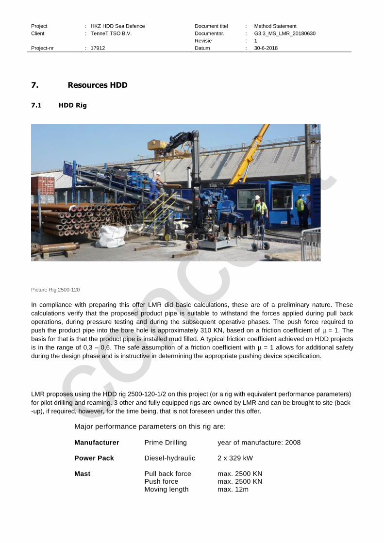
Picture Rig 2500-120
In compliance with preparing this offer LMR did basic calculations, these are of a preliminary nature. These
calculations verify that the proposed product pipe is suitable to withstand the forces applied during pull back
operations, during pressure testing and during the subsequent operative phases. The push force required to
push the product pipe into the bore hole is approximately 310 KN, based on a friction coefficient of µ = 1. The
basis for that is that the product pipe is installed mud filled. A typical friction coefficient achieved on HDD projects
is in the range of 0,3 – 0,6. The safe assumption of a friction coefficient with µ = 1 allows for additional safety
during the design phase and is instructive in determining the appropriate pushing device specification.
LMR proposes using the HDD rig 2500-120-1/2 on this project (or a rig with equivalent performance parameters)
for pilot drilling and reaming. 3 other and fully equipped rigs are owned by LMR and can be brought to site (back
-up), if required, however, for the time being, that is not foreseen under this offer.
Major performance parameters on this rig are: Manufacturer Prime Drilling year of manufacture: 2008 Power Pack Diesel-hydraulic 2 x 329 kW Mast Pull back force max. 2500 KN Push force max. 2500 KN Moving length max. 12m

Project : HKZ HDD Sea Defence Document titel : Method Statement
Client : TenneT TSO B.V. Documentnr. : G3.3_MS_LMR_20180630
Revisie : 1
Project-nr : 17912 Datum : 30-6-2018
Rotary Drive Torque / RPM 3. gear 120 kNm / 20 RPM 2. gear 80 kNm / 30 RPM 1. gear 40 kNm / 60 RPM Break-away vices Torque 180 kNm Diameter 3“ – 16“ Dimension (separable)
Length 15,50 m Width 2,50 m
Drilling Angle 5° - 25° Weight Rig 2 x 20 to Power pack 20 to Control Container 4 to
The equipment listed below is used in addition to the above rig, data sheets of the equipment are attached to this method statement:
1 piece Mud Mix Tank
1 or 2 pieces High Pressure Pump
1 piece Mud Mix Unit
1 piece Workshop Container
1 piece Spares Container
1 piece Crew Container
1 piece Pit pump
1 piece Mobile Break away vice
88 pieces Rollers
≈ 70 pieces Drill pipes 6 5/8” and /or 7 5/8“
1 piece Steering probe
3 pieces Fuel tank
1 piece Pipe pusher
7.2 Pipe Pusher

Project : HKZ HDD Sea Defence Document titel : Method Statement
Client : TenneT TSO B.V. Documentnr. : G3.3_MS_LMR_20180630
Revisie : 1
Project-nr : 17912 Datum : 30-6-2018
General information
Project : HKZ HDD Sea Defence Document titel : Method Statement
Client : TenneT TSO B.V. Documentnr. : G3.3_MS_LMR_20180630
Revisie : 1
Project-nr : 17912 Datum : 30-6-2018
8. Rigging up
The areas, described hereafter, are required for rigging up the HDD equipment.
Rig Site (Entry point, based on file ONL-TTB-04085-AT001--Land_station_Construction_area_HDD)
Length (north - south): 124 m Width: 50 – 65 m m Area: ≈ 7130 m² Hard standing area, (included in above area): ≈ 1000 m² m²
Pipe Site (Exit point, based on file ONL-TTB-04085-AT002- HDD profile Sea Defence)
Length per outfall at sea bed (north-south): ≈ 120 m Width per outfall (east - west): ≈ 40 m Area: ≈ 4800 m²
The areas defined accessible for use by the contractor and shown in the tender documents are of sufficient
nature, whereby concerns exist on the sustainability of the dredging of the pockets.
The transport of HDD equipment to site takes place with heavy goods vehicles (HGV) i.e. standard road trucks.
The rig is transported on a low-loader trailer. As mentioned before, access roads to the job site must allow such
trucks to access the job site at any time. It must also be possible to turn a truck on site.
A dead man construction/abutment is required to anchor the rig and to transfer the applied push, pull and torque
forces to the ground. As described before sheet piles, are preferred on this project anchor the rig. An adapter
structure will be used to anchor the pipe pusher with that rig anchor as well. The installation method, dimensions
and position of the rig anchor are defined during detailed design. Usually, the rig anchor is built prior to arrival of
HDD equipment on site. That can happen simultaneous to the preparation of the site hardstanding. In this regard
we would like to draw your attention that it is recommended to position the rig anchor in a minimum distance of
three meters to other utilities, for reasons of safety on site. The safe minimum offset of the drill alignment to
utilities depends on ground conditions but typically should be a minimum of 2 m vertically and 1 m horizontally.
Please find attached to this method statement generic drawings for a job site layout and a rig anchor.
8.1 Soil Situation
Soil investigations for this HDD crossing have been carried out. As part of the tender documents we received the
following site investigation information:
File: „ONL-TTB-04112-AT001-E7-HKZ-HDD Geotechnisch sondeeronderzoek DINO“
According to these documents and on a summarized basis the following soil conditions will be encountered: jet-
able sands.

Project : HKZ HDD Sea Defence Document titel : Method Statement
Client : TenneT TSO B.V. Documentnr. : G3.3_MS_LMR_20180630
Revisie : 1
Project-nr : 17912 Datum : 30-6-2018
In this regard LMR confirms that the known soil risk is with LMR, in compliance with “Information Notice 3 (BAFO
phase) Hollandse Kust (zuid) HDD Sea Defence(10140479)”.
The above summary on soil conditions is also the basis for our commercial quotation as well as for this method
statement. Should subsequent soil investigations contradict these assumptions, we would be pleased to adapt
our commercial quotation and method statement.

Project : HKZ HDD Sea Defence Document titel : Method Statement
Client : TenneT TSO B.V. Documentnr. : G3.3_MS_LMR_20180630
Revisie : 1
Project-nr : 17912 Datum : 30-6-2018
8.2 HDD Profiles
A drilling profile (long section and plan) has been provided as part of the tender documents. (Drawing “ONL-
TTB-04085-AT002- HDD profile Sea Defence.pdf”)
The main parameters of the proposed profile are:
Entry Angle 16°
Straight downward section 61,31 m
Radius 1 R = 400 m
Diagonal, straight section 179 m
Radius 2 R = 400 m
Straight Upward Section 45,52 m
Exit Angle 14°
Horizontal length 495,27 m
Drilling length ≈ 500 m
Maximum Depth -24,94 m under Entry Point
Due to the location of the exit point this position can only be accessed by boat, but not by car.
The above described drilling profile, provided with the tender documents, will be subject of slight modification
during the engineering phase to enable push reaming operations. These demand at least on the final 50 m of the
drill alignment a straight line towards the exit point. The general approach will focus on staying as close as
possible to the design, described in the table above.
8.3 Execution Time – Programme
In accordance with the tender file: “ONL-TTB-04067-MA---C2-Requirements_initial_detailed_time_programme”,
the Client plans the project physical execution in the period between April 1st 2019 and June 28th 2019 (in
accordance with files: 1.: ONL-TTB-04080-MA-D3-Permits_and_Licences and 2.: ONL-TTB-04114-AT001---F2-
HKZ HDD Sea Defence-Payment_Milestone_Schedule). From our point of view this schedule is related to some
risks, which are described later. Including mobilisation and demobilisation of the HDD equipment we expect
approx. 5 weeks of HDD operations to be required for this crossing, if the LMR HDD approach should be
acceptable to TenneT.
We have prepared and attached a preliminary program based on the execution period indicated by the client.
This program shows the time we have considered and used to calculate the cost for each single operation.
During project preparation and engineering a detailed program will be developed in close co-operation with the
Client and all other relevant parties.
The weather risk, described in the tender documents, is covered for the operations, described here, for the period indicated in the tender documents. Consequently, operations may be stopped or altered, if weather conditions do not allow working on- or near shire in safe manner. Pipe installation operations will only take place, if the weather forecast indicates a sufficient good weather window. In compliance with the tender documents we understand that such timely deviation is not subject of penalties.
8.4 Project Restrictions
According to the tender documents the following obligations have to be fulfilled:
Project : HKZ HDD Sea Defence Document titel : Method Statement
Client : TenneT TSO B.V. Documentnr. : G3.3_MS_LMR_20180630
Revisie : 1
Project-nr : 17912 Datum : 30-6-2018
1. Tennet SHE rules
2. ONL-TTB-04080-AT001--D3-Nautical_Requirements_Port_of_Rotterdam_signed
3. ONL-TTB-04080-AT002-D3--Permit requirements HDD
4. ONL-TTB-04080-AT003---D3-Leidingenvergunning gemeente Rotterdam HKZ
5. ONL-TTB-04080-MA-D3-Permits_and_Licences
8.5 Project-Specific Characteristics On this project, special attention has to be given to the following characteristics:
These are for example:
o the multiple lines near the entry points, which must be crossed.
o The Maasvlakteweg as main access road to Yangtzeehaven, which must be crossed
o The dyke, which must be crossed
o difficult access to exit point due to Port of Rotterdam permit restrictions and the fact, that this point is
located in a sub-sea environment
o A possible temporary pipe stringing or -parking area behind the exit point may extend in the shipping
lane, a fact which can create dangerous situations with big vessels which may run into conflict
avoiding such situation – reference is made to the port authority permit.
o environmental obligations, whereby the impact of these cannot be overseen at this moment.
8.6 Sources for additional Information Besides the tender documents LMR has used the following sources to prepare this quotation:
A site visit, that was carried out on April 12th 2018.
8.7 Drill Mud – Bentonite
The term “mud” reflects all fluids, circulating in the bore hole during drilling works. For the horizontal directional
drilling technique, carried out near surface (< 100 m), these are slurries whose composition and parameters
have to be customized to geological and drilling demands.
The fresh water slurry, mostly used in HDD, is a bentonite based mud and fulfils the functions listed below:
hydraulic cutting of solids by jetting,
hydraulic powering of mud motors,
sealing and stabilisation of the bore hole by creating a hydrostatic counter pressure on the bore hole wall,
carrying drilled solids to surface,
maintaining the suspension of solids in the mud when the mud flow is stopped (e. g. due to pump stop),
lubrication and thus reduction of friction of the drill string, drill assembly and product pipe.
The mud must have many special characteristics to fulfil these tasks. For bentonite based fluids fresh water is
the basis for the mud system being used on site. If project demands require, additives can be used. These are
mostly natural substances, e. g. polymers on starch basis, viscosity or pH-value regulating additives.

Project : HKZ HDD Sea Defence Document titel : Method Statement
Client : TenneT TSO B.V. Documentnr. : G3.3_MS_LMR_20180630
Revisie : 1
Project-nr : 17912 Datum : 30-6-2018
As mentioned above water is required to mix mud. That water must be available in sufficient quality and quantity.
Fresh water with a salt content of less than 1000 mg NaCL/Liter is required.
We have assumed that water is locally available. A total quantity of approximately 2.400 m³ is required. Peaks of
80m³/h are possible.
8.7.1 The parameters listed below are monitored and maintained on site during drilling works:
density,
viscosity (Funnel Viscosity, plastic viscosity, yield point),
API water loss, filter cake,
pH-Value
solids content.
LMR commits a qualified and experienced mud engineer to this project for mud monitoring and conditioning, as
the quality of mud is of essential importance for a successful completion of HDD works. That mud engineer is
already involved during works preparation and in the composition of the drilling programme.
When HDD works are done, surplus mud volume is left over. That mud is usually stored on site (on a temporary
basis) until it can be re-used or disposed.
We suggest building mud lagoons in this regard. Lining the mud lagoons is not recommended for technical- and
environmental reasons (avoid use of plastics).
Lagoons are proposed with a total storage capacity of < 500 m³ rig site. To avoid that these create a danger we
suggest building these with a sloped wall, 45° angle and having a 0,5 m wide top and a filling depth of < 1,5 m
(to reduce the risk of drowning).
Container units can be used as well but are not foreseen to be used for the time being, as these will create
negative impact in the CO2 balance when it comes to transport, setting these up and setting these down.
Lagoons are also proposed for intermediate storage of separated materials. We assume that about 4500 to of
material will be separated, equating to ≈ 2500 m³
8.7.2 Mud circuit
Fresh mud is mixed with water and bentonite. That is pumped with support of the high pressure pump through
the drill string and the drill tools to the bottom of the bore hole. There, the mud starts flushing the drilled solids.
The mud then flows with these solids along the annulus (between the outside of the drill string and the borehole
walls) to surface. As the mud reaches surface it is collected in a storage pit, where it is pumped to a recycling
unit. The solids are separated from the mud at the recycling unit. The separated mud remains in the mud circuit
and is pumped to a mud mix tank. There it is controlled for its rheological parameters, re-conditioned, if required
and then pumped again in the bore hole with support of the high pressure pump. The product pipe displaces its
own volume of mud during the pullback process. That quantity plus material left over in tanks and pits are first
stored (e. g. in lagoons or container units see above) and are then removed from site.

Project : HKZ HDD Sea Defence Document titel : Method Statement
Client : TenneT TSO B.V. Documentnr. : G3.3_MS_LMR_20180630
Revisie : 1
Project-nr : 17912 Datum : 30-6-2018
schematic sketch mud circuit
8.7.3 Mud transfer
Mud transfer from pipe site to rig site won’t happen on this project, reason for that is the offshore nature of the
exit point and the limited possibilities to install adequate infrastructure to do so.
However, to reduce mud spillage at the sea bed for such jobs, LMR has developed a drilling approach and
practised it successfully for 15 years that will be described hereafter and, in the section, “reaming”, later as well.
The bore hole is open to rig site only and closed at the target side, during most part of the drilling works. During
the subsequent hole-opening operations, the mud, pumped through the drill string and the drilling assembly into
the bore hole, can flow to the surface at the open end of the bore hole = rig site at land surface. This depends on
a number of hydraulic factors, especially the annulus geometry, the length of the bore hole and any difference in
elevation between both ends of the bore.
Recycling, reconditioning and pumping of the mud are done on rig site. Reaming of the bore hole on other
projects is usually done by pulling. Here, the reaming assembly is pushed through the bore hole from rig to pipe
site (while the drill string is rotated, while mud is pumped through the drill string and while drill pipes are added
on rig site). During that operation mud is discharged to surface on rig site. Only when the breakthrough to the
seabed is done, small amounts of mud will be discharged to the sea. The same applies to the pipe/duct
installation process, when mud is displaced. The mud accessing the seabed at pipe site will be reduced to a
minimum.
All that will be achieved by stopping pilot drilling operation about 20 m before exit point at the sea bed in order to
keep the bore hole towards the sea bed closed. Then the pilot drilling assembly will be pulled out of the hole,
while the bore hole will be sealed and stabilized with a specially formulated mud. Afterwards the bore hole will be
push-reamed from rig site to the final diameter. More related information is shown in the sections hereafter.
8.7.4 Disposal / Recycling / Waste Management
During all working stages waste of different nature may apply. Waste will be collected and separated to the
extend feasible and manageable. Disposal of that waste will be done through certified disposal companies, only.
Disposal certificates will be filed and put into the drop box.

Project : HKZ HDD Sea Defence Document titel : Method Statement
Client : TenneT TSO B.V. Documentnr. : G3.3_MS_LMR_20180630
Revisie : 1
Project-nr : 17912 Datum : 30-6-2018
With the progress of HDD works, solids are separated from the mud/bentonite and mud is displaced during the
pipe installation operation. Depending on local legislation and the quality of material, the separated solids and
the displaced mud can either be re-used (e. g. in agricultural business, nowadays not feasible) or this material
has to be disposed on a professional basis.
It is common practise that ways for waste management are defined prior to commencement of HDD works. In
compliance with that random samples are taken from separated solids and mud when drilling works start (during
pilot drilling). These samples are taken by accredited laboratories that analyse these in compliance with local
relevant guidelines and laws. A final decision on how to proceed with the re-use or possible disposal of
separated solids and displaced mud depends on the results of this analysis. Only legally applicable disposal will
be done.
The transport of mud off site takes place with vacuum trucks. The separated solids can be transported off site
with closed dumpers.
8.7.5 Quantities
On this project we assume the quantities, listed hereafter, will apply:
Water to mix mud: approximately 2.400 m³
Surplus mud after all ducts are installed approximately < 1.700 to = 1.300 m³
Surplus separated solids: approximately 4.450 to = 2.500m³
The density of surplus mud is in the range of 1,2 – 1,3 tonnes per m³. The density of separated solids is in the
range of 1,8 tonnes per m³.
8.8 Pilot Drilling
Drilling wise three major working steps can be defined on a HDD jobsite. These are:
pilot drilling,
reaming/enlarging the bore hole (one or more steps, if required),
installation of the product pipe, here the cable ducts
The pilot drilling works are carried out along a designed drilling trajectory. This starts at the entry point (in front of
the drill rig) and ends at the exit point, located at the opposite site of the “obstacle” to be crossed by means of
HDD.
A drill string consists of a drill assembly and drill pipes. The first component of that drill assembly is the drill bit
that aims for cutting the soils to be penetrated. Depending on the physical composition of soils, this can be a jet
bit (jetting) or a rock bit (rock drilling), if required in combination with a mud motor. The jet bit works on a
hydraulic basis whereas the rock bit works on a combined hydro-mechanical basis. The diameter of any pilot drill
bit will always be bigger than the diameter of the drill pipes, installed behind that bit.

Project : HKZ HDD Sea Defence Document titel : Method Statement
Client : TenneT TSO B.V. Documentnr. : G3.3_MS_LMR_20180630
Revisie : 1
Project-nr : 17912 Datum : 30-6-2018
The drill bit is followed by a bent sub. In most cases the bent sub shows a bend of 0,5° - 2,5°, depending
(amongst other factors) on soil conditions to be penetrated. The bent sub causes the eccentricity required to drill
a curved alignment when the drill assembly is pushed forwards without rotation. If the drill assembly is rotated,
then the working direction of the drill bit will change. As such the controlled and co-ordinated rotation of the drill
assembly allows drilling any designed direction.
Drill assembly is rotated and pushed forwards => drilling direction straight forwards
Drill assembly pushed forwards without rotation=> drilling direction along a designed HDD trajectory
Depending on soil conditions the decision is made whether a jetting or rock drilling assembly is used.
In compliance with the known soil conditions we suggest using the jetting technique for pilot drilling. Based on
the given information LMR proposes using a 12 1/4” MT TriCone jet bit. The anticipated diameter for the pilot
bore in sand is ≈ 350 mm. This rather large diameter allows reducing annular pressure in the bore hole and will
help to avoid mud break outs.
Using the processes listed hereafter, we believe we are able to significantly reduce the risk of drill fluid losses:
detailed mud pressure calculation during works preparation,
choosing a sufficient sized pilot bore hole diameter,
compilation of target values for the drill rig operator,
use of a PWD tool (Pressure While Drilling Tool; PWD, measures
the annulus pressure during pilot drilling behind the drill bit),
Project : HKZ HDD Sea Defence Document titel : Method Statement
Client : TenneT TSO B.V. Documentnr. : G3.3_MS_LMR_20180630
Revisie : 1
Project-nr : 17912 Datum : 30-6-2018
utilisation of high quality mud products,
assigning a qualified and experienced drilling fluid engineer to the job site,
for permanent control and conditioning of the mud system.
The anticipated pump rate during pilot drilling works is 1000 - 1400 l/min. Based on the above pump rate and the
soil conditions, described in our offer we anticipate an average progress rate for pilot drilling works of
approximately 340 m per day!
8.8.1 Casing installation
We suggest stabilising the start section of the crossing by installing a casing pipe. The reasons for this are the
given soil conditions in combination with the plenty of foreign utilities to be crossed. We suggest using DN 1200
mm steel casing pipes. These are installed prior to pilot drilling operations with support of a pneumatic hammer.
That casing won’t be pulled out of the bore hole after drilling operations are finished. It can be cut off below
ground surface.
8.8.2 GYRO
We suggest using an optical gyro based steering system for steering bore hole surveying. That system, named
Drill Guide, is provided by Brownline B.V.. It is extremely accurate and is unsensitive to any magnetic
interference. The installation of a cable grid on surface is not required.
The DrillGuide system allows achieving the surveying accuracy shown hereafter: Inclination 0,01°
Azimuth 0,04°
Tool Face 0,02°
The steering accuracy, required for this project, can be achieved with the above described steering system. It
needs to be noted that the accuracy for pilot drilling does not only depend on the surveying and steering system,
it depends on soil conditions and related steerability of the HDD assembly in these as well.
Based on the given soil information and as mentioned above, we anticipate an average drilling progress per day
of 340 m. That progress rate forms the basis of our quotation and the attached schedule. Detailed information on
the drilling programme will be compiled during detailed engineering (after contract award).
Pilot drilling works are finished with the pilot drilling assembly punching out at surface in the designated area.
Afterwards the pilot drilling assembly is disconnected from the drill string.
Tolerances during pilot drilling operations:
Based on our experience and based on given soil information we assume that a radial rectangular off-set < 2 m
can be achieved in correlation to the pilot drill alignment with the proposed gyro based jetting tools for pilot
drilling.
8.8.3 Pressure While Drilling Tool
We propose using on this project a „Pressure While Drilling“ tool (PWD). That tool is used as an upgrade to the
bore hole surveying system and measures the annulus pressure behind the drill bit during pilot drilling works.
Related data on annulus pressure are sent to surface on a continuous basis, where these can be used by the
driller and the mud engineer. In case of sudden changes of the annulus pressure, such data is available at the

Project : HKZ HDD Sea Defence Document titel : Method Statement
Client : TenneT TSO B.V. Documentnr. : G3.3_MS_LMR_20180630
Revisie : 1
Project-nr : 17912 Datum : 30-6-2018
earliest possible notice, allowing timely and adequate adjustments of the drilling procedures. Such adjustments
allow the risk of mud losses in the bore hole and to surface to be reduced effectively.
8.8.4 Push reaming
As announced before and based on local site conditions LMR suggests using the push reaming technique on
this project.
The first working step – pilot drilling – is done with a rather big pilot drill assembly (12 ¼”, see picture 1),
whereby the mud pressure, near the pilot bit, is permanently monitored and controlled.
Phase 1 : Pilot Drilling as a sack-hole
The pilot hole ends at a distance of 20 m – 30 m before the exit point at the sea bed. Then the pilot string is
tripped back to surface, whereby this operation is used to fill the bore hole with fresh, reconditioned mud.
After the pilot drilling assembly is back at surface it is disconnected and replaced against a specialised push
reaming assembly. That assembly consists of a self-centralising and cone-shaped bull nose, including a steering
probe, that is followed by an unique jetting-reaming tool with a diameter of 44” (= 1118 mm). That assembly is
rotated down the borehole. At the same time minimum 2000 litres of mud are pumped per minute through the
drill string/assembly, enabling the enlargement of the bore hole to the final diameter in about 3 days.
That mud will flow to the entry point at surface, as the front section of the bore hole is closed towards the sea
bed. All necessary cleaning runs, if any should be required, will be executed with the borehole closed towards
the sea. Only at the very last moment, where and when the push reaming assembly breaks through to the sea
bed a minor quantity of mud will float to the sea bed. As indicated, here, the above working steps continue until
the push reaming assembly reach surface on pipe site = at the sea bed.

Project : HKZ HDD Sea Defence Document titel : Method Statement
Client : TenneT TSO B.V. Documentnr. : G3.3_MS_LMR_20180630
Revisie : 1
Project-nr : 17912 Datum : 30-6-2018
Phase 2: Push Reaming
After emergence at the sea bed air can be pumped through the push reaming assembly to verify the assembly’s
position. If that should not be desired the push reaming assembly is tripped out the bore hole.
Advantages of the push reaming method
By using the push reaming, the benefits, shown below, are achieved for this project. Those advantages were in
the past highly appreciated by Tennet on land fall projects, located in the German Wadden Sea:
A drastic reduction of mud pressure in the annulus, thus greatly
reducing the risk of mud blow outs on surface, especially near the exit point.
Improved steerability of the pilot drilling assembly.
The completion of all drilling activities, whereby the mud return flow will take place (almost permanent) to the rig site only. In compliance with that, no mud handling at the exit point is required
No pipe-site installation is required, as it would be for the handling of pipe-site starting reamers or trailing drill pipe.
No or reduced interaction with shipping lane in/out Rotterdam Port, depending on the pipe installation handing over parameters to be agreed on.
Under normal conditions it is recommended that the final bore hole diameter is 1,2 – 1,5 times bigger than the
diameter of the product pipe.
We suggest reaming the pilot bore hole to the final diameter in one step on a pushing basis.
The reaming steps, shown hereafter, are proposed:
Step one 1118 mm = 44”

Project : HKZ HDD Sea Defence Document titel : Method Statement
Client : TenneT TSO B.V. Documentnr. : G3.3_MS_LMR_20180630
Revisie : 1
Project-nr : 17912 Datum : 30-6-2018
The anticipated pump rate during reaming works is 2000 l/min. Based on this pump rate and the soil conditions
described in our offer, we anticipate an average progress rate for reaming works of approximately 200 m per day.
The final works programme, regarding the reaming steps, is defined during the drilling works and can depend on
the encountered soil conditions.
As described before in the section ‘mud transfer’ it is proposed push-reaming the bore hole to the final diameter.
Tolerances push reaming operations:
Based on our experience and based on given soil information we assume that a radial rectangular off-set < 5 m
can be achieved in correlation to the given drill alignment at exit point.
8.8.5 Cleaning Run / Checktrip
An optional cleaning run can be made based on the results of the bore hole cleaning analysis to be carried out
during and after reaming works. Unsatisfactory results may lead to such a cleaning run. On such a cleaning run
the bore hole is again passed with a reaming tool that is pulled or pushed through the bore hole, depending on
project demands. During these works fresh mud can be pumped into the bore hole.
8.8.6 Stone catcher
The bore hole can be accessed with a stone catcher during- or after reaming works are finished. The reason for
using that tool are indications, such as deviations between calculated and encountered forces on the drill string
(torque-, pull- and push forces), which can implicate the presence of gravel, stones or boulders. In such
circumstances this tool can be used. Its shape is a combination of a fly cutter tool with a bow net, typically a steel
basket. This allows stones in the borehole to be collected with a maximum diameter of approximately 1/3 x the
tool diameter. As soil conditions and related investigation reports do not indicate the need for such operations
these are not foreseen to be carried out. However, please note that LMR is in possession of such tools, which
can be mobilised to site at short notice, if required. With the given status on soil information we do not expect
having to use such tool on this project.
8.9 Duct installation
The installation of the prepared HDPE cable duct into the bore hole is the final step on an HDD project. Here, it
is the final step of HDD operations for each single outfall.
The above requires sufficient space in a straight prolongation of the drilling trajectory on rig site behind the entry
point, aiming for the completion of one complete pipe duct string. The width of that working area is normally as
wide as the open cut/trenched working areas.
The length of the pipe stringing area/prefabrication area is the sum of the total length of the product pipe string
plus the length of the overbend construction, described below.
Prefabricating the complete product pipe string aims for performing the duct installation operation without
interruption. Connecting segments of duct pipe strings is a risk-increasing factor that should be avoided.

Project : HKZ HDD Sea Defence Document titel : Method Statement
Client : TenneT TSO B.V. Documentnr. : G3.3_MS_LMR_20180630
Revisie : 1
Project-nr : 17912 Datum : 30-6-2018
Phase 3: Installation of the HDPE Conduit pipe by use of a pipe pusher
The prefabricated product pipe is positioned on rollers prior to pull back. Near the entry point the prefabricated
product pipe is guided over a pre-defined overbend construction. This overbend construction guides the
prefabricated product pipe smoothly and safely into the bore hole.
A draft lay out of that overbend - structure and -alignment is shown in the drawings attached to this method
statement.
For pushing the pipe into the bore hole, a unique pipe pusher will be assigned to this site on an exclusive basis.
For installing this device, the drill rig will be repositioned, after reaming works are finished to satisfaction. The
achievement of that “satisfactory” status is given by forces, measured on the drill string, measurements of the
quantity of material separated from the mud and a control of solids content in the mud returning from the bore
hole to surface at the entry point.
Once the pipe pusher is in position, a process that may take 6-8 hours, the pipe will be guided with crane and/or
excavator support into the pipe pusher. This device, working on the same principle as a tensioner for offshore
installation of cables or pipes, will push the HDPE pipe in controlled manner into the bore hole.
For a better understanding of this device we refer to the attached references and data sheets.
For easing the subject pipe pushing process, which has been done in the past over longer lengths (1200 m) with
less robust HDPE-pipes (OD 700 mm) a specialised cone shaped front section will be supplied by LMR.
That front section will allow pumping mud through the PE-duct during push installation, if required. In this regard
LMR would like to mention that LMR has push installed cable ducts since 2013 with great success over lengths
up to 1650 m, also in more severe soil conditions.
In addition to that, the front section will have openings, allowing mud to flow into the pipe. That will reduce
buoyancy during the pushing process in the bore hole and will reduce therefore significantly friction on the pipe
body and the bore hole wall as well.

Project : HKZ HDD Sea Defence Document titel : Method Statement
Client : TenneT TSO B.V. Documentnr. : G3.3_MS_LMR_20180630
Revisie : 1
Project-nr : 17912 Datum : 30-6-2018
Furthermore, the design of this front section will allow pumping air through the cable duct. Air pumping can be
utmost relevant for an easy identification of the duct arrival at sea bed and for confirming the proper position in
the pre-dredged pocket.
(Air pumping for duct position identification in the pre-trenched pocket or at sea bed is proposed to be done at
the turn-point of tides, preferably at day time, as then no or limited current impact will deviate the approach of air
bubbles at sea surface).
A flap trap valve, installed inside the front section, will avoid that the mud or air nozzles are jammed
The subject front section itself is connected to the cable duct on a flange-based system, which can later, for
installation of the cable, be replaced against a bell mouth system matching the demands of the cable contractor.
That replacement can happen either by ROVs or by divers.
All the above features are being considered a complex risk reducing approach.
The pullback operation displaces mud that must be collected on surface. The displaced mud can be stored in
lagoons on a temporary basis. The sum of that displaced mud will be limited, probably to > 50 m³, as the opening
in the front section will allow mud to enter the pipe.
The targeted progress rate for the pipe push operation is 200 - 300 m per hour.
8.10 General note
LMR is not convinced that the top view of the pockets is of advantage. Same applies to that fact that the pockets
appear being left unattended after having made these. Both above topics show a considerable risk to the
successful execution of HDD works. The approach proposed by LMR can be easily adapted to a trenchless
solution, which would reduce TenneT worries with maintaining the pockets over some months. LMR is prepared
discussing such approach during a bid meeting.
8.11 Rigging down
The HDD equipment will be cleaned and prepared for transport off site after the successful pull back of the last
product pipe. Loading of the equipment takes place with the support of a crane. The mud and the separated
solids, stored on site, are disposed in compliance with local regulations, as described previously.
Surfaces are re-instated, in accordance with contractual agreements, after the transport of drilling equipment off
site is complete.

Project : HKZ HDD Sea Defence Document titel : Method Statement
Client : TenneT TSO B.V. Documentnr. : G3.3_MS_LMR_20180630
Revisie : 1
Project-nr : 17912 Datum : 30-6-2018
9. Marine Assistance
9.1 Resources
Ms Noordzee
Name Ms Noordzee
Type of vessel Multipurpose vessel
Dimensions 66.5 * 15.0 * 2.1 mtr
Draft min. 1.5 mtr
Draft max. 2.1 mtr
Class Lloyds (coastal waters 5 nautical miles working zone)
Cargo capacity 1500 ton
Sennebogen 6180 HD
Brand Sennebogen 6180 HD
Lifting capacity 280 ton
Main boom length 60 mtr

Project : HKZ HDD Sea Defence Document titel : Method Statement
Client : TenneT TSO B.V. Documentnr. : G3.3_MS_LMR_20180630
Revisie : 1
Project-nr : 17912 Datum : 30-6-2018
Sennebogen 6180 HD
Aux. boom length 60 mtr
9.2 CREW/TUGBOAT
During all near shore activities there will be a crew/tugboat alongside / nearby the Ms Noordzee. In case of
emergency the crew/tugboat will be the first option to leave or enter the working area. During the position of
the Ms Noordzee, the crew/tugboat will be assist as back up, in the unlikely situation something happens with
the DP-system.
The crew/tugboat is allowed to work nearshore and have enough bollard pull which are needed for all common
near shore marine activities.
Figure 5: Crew/tugboat (or similar)
9.3 GUIDING VESSEL
Besides the marking buoys and the crew/tugboat, there will be a competent guiding vessel nearby the working
zone. This guiding vessel has the authority to instruct en guide the vessels on the Nieuw Waterweg. The guiding
vessel will be in close contact with the Port of Rotterdam Authorities and provides a safe working area for our
works and a safe travel in the shipping lane.
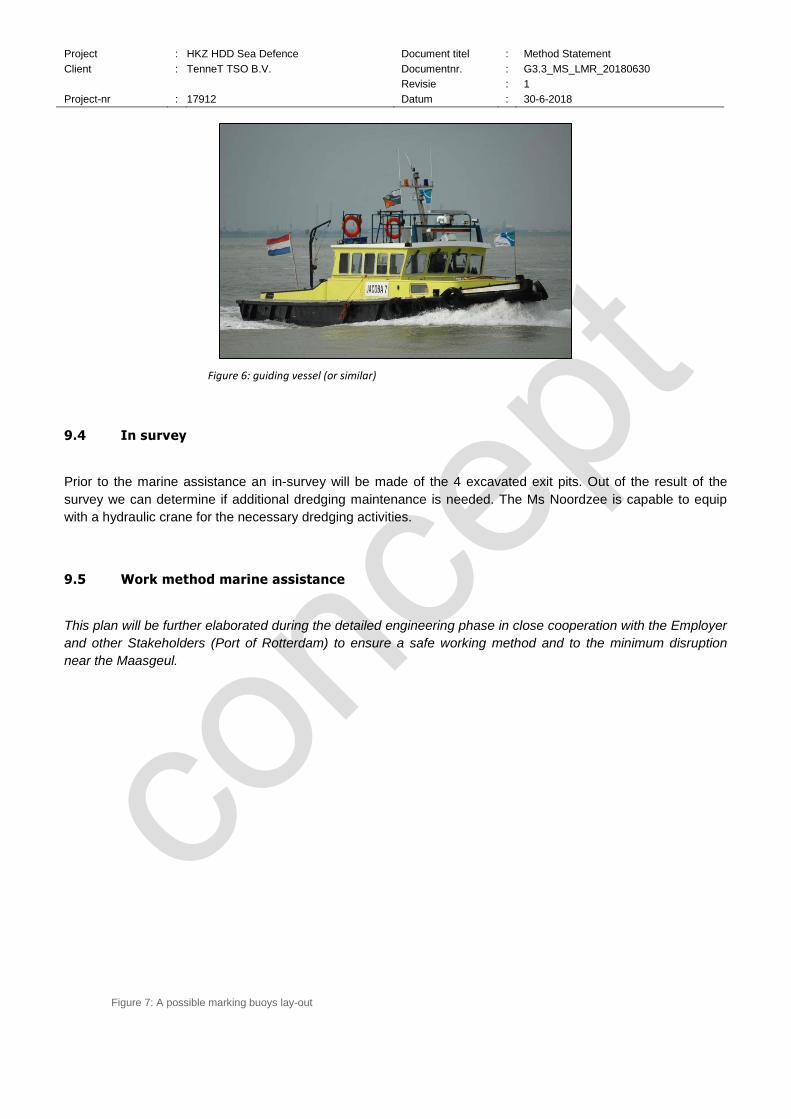
Project : HKZ HDD Sea Defence Document titel : Method Statement
Client : TenneT TSO B.V. Documentnr. : G3.3_MS_LMR_20180630
Revisie : 1
Project-nr : 17912 Datum : 30-6-2018
Figure 6: guiding vessel (or similar)
9.4 In survey
Prior to the marine assistance an in-survey will be made of the 4 excavated exit pits. Out of the result of the
survey we can determine if additional dredging maintenance is needed. The Ms Noordzee is capable to equip
with a hydraulic crane for the necessary dredging activities.
9.5 Work method marine assistance
This plan will be further elaborated during the detailed engineering phase in close cooperation with the Employer
and other Stakeholders (Port of Rotterdam) to ensure a safe working method and to the minimum disruption
near the Maasgeul.
Figure 7: A possible marking buoys lay-out

Project : HKZ HDD Sea Defence Document titel : Method Statement
Client : TenneT TSO B.V. Documentnr. : G3.3_MS_LMR_20180630
Revisie : 1
Project-nr : 17912 Datum : 30-6-2018
9.5.1 Installation marking buoys according annex 1;
Nautical requirement Port of Rotterdam.
Installation of the buoys will be done by a recognized support vessel of the Dutch Ministry of Infrastructure.
Location of the buoys in relation to our required working space, will be discussed and aligned after assignment.
9.5.2 Placing guiding
poles.
Before the first horizontal
directional drilling (HDD)
starts, eight number of
guiding poles will be
installed at the exit point,
two guiding poles each
HDPE pipe. The location
and lay-out of the guiding
poles are described in
figure 8 and 9.
Just before the HDD
reach the end of exit point,
a lifting sling will be
installed between two of
the guiding poles, displayed in figure 9. This way there are no divers required to pick up the HDPE pipes
from the seabed and guided the PE pipe up to the working deck of the Ms Noordzee.

Project : HKZ HDD Sea Defence Document titel : Method Statement
Client : TenneT TSO B.V. Documentnr. : G3.3_MS_LMR_20180630
Revisie : 1
Project-nr : 17912 Datum : 30-6-2018
Figure 8: Guiding poles location and lay-out.
Figure 9: Guiding poles layout

Project : HKZ HDD Sea Defence Document titel : Method Statement
Client : TenneT TSO B.V. Documentnr. : G3.3_MS_LMR_20180630
Revisie : 1
Project-nr : 17912 Datum : 30-6-2018
9.5.3 Positioning the vessel ‘Ms Noordzee’ in the extension of drilling hole.
The Ms Noordzee will be positioned in the extension of the drilling hole, within the marking buoys. In this
way the crawler crane on board of the vessel is able to guide the HDPE pipe safely on deck. In this
stage of the operation the Ms Noordzee is stabilised on her spud poles and provide a safe a stable
working area for the crew. The position of the Ms Noordzee is explained in figure 10. To avoid any
damage while guiding the HDPE pipe on deck, a customized stinger will be installed at the stern of the
vessel. A sketch design of the stinger is added in figure 11
Figure 10: Starting position MS Noordzee.

Project : HKZ HDD Sea Defence Document titel : Method Statement
Client : TenneT TSO B.V. Documentnr. : G3.3_MS_LMR_20180630
Revisie : 1
Project-nr : 17912 Datum : 30-6-2018
Figure 11: Sketch design stinger
9.5.4 Tests PE pipe
After placing the HDPE pipe on deck, it will be secured with lashing belts. All the required tests can now
be executed in a safe way from the Ms Noordzee. In this stage of the operation the Ms Noordzee is still
stabilised on her spud poles.

Project : HKZ HDD Sea Defence Document titel : Method Statement
Client : TenneT TSO B.V. Documentnr. : G3.3_MS_LMR_20180630
Revisie : 1
Project-nr : 17912 Datum : 30-6-2018
9.5.5 Placing rock bags on top of the PE pipe.
The HDPE pipe will be installed with an overlength of approx. 100 meters on the seabed. The HDPE
pipe will be ballasted with rock bags to prevent it from moving in the horizontal and vertical direction.
The rock bags are transported by a transport barge to the site location. The barge will be moored
alongside the Ms Noordzee.
The rock bags placing starts from the exit point towards the end of the HDPE pipe, to make sure there is
no slack in the HDPE pipe. In this stage of the operation the Ms Noordzee is still stabilised on his spud
poles.
During the rock bags dumping the Ms Noordzee needs to be repositioned to make sure the PE pipe is
on the required position. During this operation the Ms Noordzee will sail with dynamic positioning, with
the possible assistant of the crew/tugboat in rough weather conditions. After repositioning of the Ms
Noordzee, the rock bags dumping will be completed. After finishing of the rock bags dumping, the
placement of the bags will be checked by survey. Repositioning of the Ms Noordzee is explained in
figure 12.

Project : HKZ HDD Sea Defence Document titel : Method Statement
Client : TenneT TSO B.V. Documentnr. : G3.3_MS_LMR_20180630
Revisie : 1
Project-nr : 17912 Datum : 30-6-2018
Figure12: Rock bags placing
9.5.6 Removing guiding poles.
After completion of the horizontal directional drilling (HDD) the guiding poles will be removed. To prevent
any damages to the just installed HDPE pipes, the Ms Noordzee will layed down parallel to the shipping
lane, using only two spud poles. Displayed in figure 13.

Project : HKZ HDD Sea Defence Document titel : Method Statement
Client : TenneT TSO B.V. Documentnr. : G3.3_MS_LMR_20180630
Revisie : 1
Project-nr : 17912 Datum : 30-6-2018
Figure 13: Removing guiding poles
9.6 Out survey
Each time the installation of a HDPE pipe is completed, a multibeam out survey will be executed. The position
of the overlength and rock bags to keep the HDPE pipes stable on the seabed will be evaluated and handed.

Project : HKZ HDD Sea Defence Document titel : Method Statement
Client : TenneT TSO B.V. Documentnr. : G3.3_MS_LMR_20180630
Revisie : 1
Project-nr : 17912 Datum : 30-6-2018
10. Contingencies
10.1 Maintenance on the HDD exit pit
A so-called DOP pump of mass Flow system will be used to clear the pits. The pump will be positioned on a the
AHT or the Installation Barge. The re-opening of the pits will take place during the ebb tide. This will avoid that
the material is moved towards the shipping channel.
10.2 Alternative HDD method
If by any reason the proposed method of Forwards reaming is no longer possible, we can convert the installation
barge to accommodate the conventional reaming method.
The conversion means that we have to adjust the outrigging structure suitable for assemble drill strings with a so
called “Rough Neck”. The “Rough Neck”is capable for breaking and torque up the drill rods.

Project : HKZ HDD Sea Defence Document titel : Method Statement
Client : TenneT TSO B.V. Documentnr. : G3.3_MS_LMR_20180630
Revisie : 1
Project-nr : 17912 Datum : 30-6-2018
11. Project finalisation
This chapter describes the activities to be completed after the cables have been installed. It describes
Contractor’s approach and added value in relation to Employer’s Requirements.
11.1 Demobilisation
Demobilisation will be done after each vessel has As-built
During and after the works Contractor will prepare and provide as-built documentation containing at least,
depending on the as-built requirements:
Data log files with PLGR tracks, tensions, sailing lines, recovered debris and positions of possible found
large debris;
Provision of complete sets of daily logs;
Provision of information required under HSE regulations as agreed with the Employer;
Survey results;
As-laid reports containing:
Route alignment sheets showing all relevant information from the as-laid reports;
Manufacturing record books of permanent items;
Part of the detailed engineering phase is provision of a so-called ‘As-built documentation procedure’, describing
the deliverables, formats and hand-over information. This to assure that the as-built documentation meets
Employer’s requirements.
11.2 Lessons learnt
Gathering and implementing lessons learnt is part of Subcontractor integrated management system, which
means that during project preparations lessons learnt from previous and ongoing projects will be collected and
implemented as much as practically possible and/or applicable. Lessons learnt will be collected from all
personnel involved in the project, i.e. from deck crew to Employer’s package management. This is done
throughout the project as well as during dedicated lessons learnt meetings after finalization of each project
phase.
All lessons learnt gathered on the projects are stored on SUBCONTRACTOR’s internal exchange server and are
accessible by all SUBCONTRACTOR personnel. Specific lessons learnt are implemented in applicable
installation procedures. Recent/new lesson are also mentioned during the project kick-off with project personnel.

Project : HKZ HDD Sea Defence Document titel : Method Statement
Client : TenneT TSO B.V. Documentnr. : G3.3_MS_LMR_20180630
Revisie : 1
Project-nr : 17912 Datum : 30-6-2018
12. Project finalisation
This chapter describes the activities to be completed after the cables have been installed. It describes
Contractor’s approach and added value in relation to Employer’s Requirements.
12.1 Demobilisation
Demobilisation will be done after each vessel has As-built
During and after the works Contractor will prepare and provide as-built documentation containing at least,
depending on the as-built requirements:
Data log files with PLGR tracks, tensions, sailing lines, recovered debris and positions of possible found
large debris;
Provision of complete sets of daily logs;
Provision of information required under HSE regulations as agreed with the Employer;
Survey results;
As-laid reports containing:
Route alignment sheets showing all relevant information from the as-laid reports;
Manufacturing record books of permanent items;
Part of the detailed engineering phase is provision of a so-called ‘As-built documentation procedure’, describing
the deliverables, formats and hand-over information. This to assure that the as-built documentation meets
Employer’s requirements.
12.2 Lessons learnt
Gathering and implementing lessons learnt is part of Subcontractor integrated management system, which
means that during project preparations lessons learnt from previous and ongoing projects will be collected and
implemented as much as practically possible and/or applicable. Lessons learnt will be collected from all
personnel involved in the project, i.e. from deck crew to Employer’s package management. This is done
throughout the project as well as during dedicated lessons learnt meetings after finalization of each project
phase.
All lessons learnt gathered on the projects are stored on SUBCONTRACTOR’s internal exchange server and are
accessible by all SUBCONTRACTOR personnel. Specific lessons learnt are implemented in applicable
installation procedures. Recent/new lesson are also mentioned during the project kick-off with project personnel.