Embed Size (px)
Citation preview

HOUSTON, TEXAS 77054
1851 CROSS POINT
HEALTH SCIENCE CENTER AT HOUSTON
UNIVERSITY OF TEXAS
ENGINEERS
http://www.eceng.com
Facsimile 713-580-8888
Telephone 713-580-8800
Houston, Texas 77002
1010 Lamar, Suite 650
E&C State of Texas registration number is F-003068
E&C Engineers and Consultants Inc.
HOUSTON, TEXAS 77030
6431 FANNIN ST.
MEDICAL SCHOOL BUILDING
HEALTH SCIENCE CENTER AT HOUSTON
UNIVERSITY OF TEXAS
JANUARY 3, 2017 100% CD
VACUUM PUMP REPLACEMENT EXHIBIT E
PROJECT DRAWINGS AND SPECIFICATIONS

SKETCH:
DRAWING:
DATE:
REVISION:
E&CEngineers & Consultants Inc.
1010 Lamar, Suite 650
Houston, Texas 77002
Tel 713/580-8800
Fax 713/580-8888
www.eceng.com
TX Firm Registration No: F-003068
SCALE:
01-03-2017
THE SEAL APPEARING ON THIS DRAWING WAS AUTHORIZED BY:
Texas Firm Registration No: F-003068
E&C Engineers & Consultants Inc.
PR
OF
ESSIONAL EN
GI
NE
ER
S
TAT
E OF TEXA
S
GEOFFREY R. LUSSIER
100281LICENSE
D
1
I:\3300\3315\M\Plumb\PENTHOUSE\3315 P SA (P000).dgn
E&C PROJECT # 3315
CHEM STO CHEM STO CHEM STO
double 55g
drum storage
double 55g
drum storage
HBFS
FS
FS
HB
FS
FS
BAND
SAW
CHEM
STO
HOOD
HB
CHEST
FREEZER
FD
CHEM
STO55g
DRUM
STO
55g
DRUM
STO
FS
FD
HB
FS FS FS
FS
HB
FS
FS FS
HB
FS
HB
FS
F.D.F.D.
FS
FS
FS
FS
FS
REF
FS
DW
MSB BASEMENT EQUIPMENT REPLACEMENT
UTHSC-H
X X
D
SD
OD
AW
AV
FS
VS
1
1 R620
aaabb
P
1
EQUIPMENT REFERENCE
OWNER OR CONTRACTOR FURNISHED
DOWNSPOUT, "F" DENOTES FIRE.
"W" DENOTES WATER, "DS" DENOTES
WASTE/VENT OR WASTE/VENT/WATER,
RISER DESIGNATION, "P" DENOTES
"bb" DENOTES NUMBER.
"aaa" DENOTES TYPE,
PLUMBING EQUIPMENT REFERENCE.
"aaa" DENOTES TYPE
EXISTING PIPE TO BE REMOVED,
"aaa" DENOTES TYPE
EXISTING PIPE,
G
M
X
FCS
X
BALANCING/STOP VALVE
GATE VALVE, HVAC
DIFFERENTIAL PRESSURE TAPS
BALANCING VALVE WITH
CONTROL VALVE
TWO-WAY MODULATING
CONTROL VALVE
THREE-WAY MODULATING
GAUGE COCK
PRESSURE GAUGE WITH
STATION
SPRINKLER FLOOR CONTROL
FLOW/TAMPER SWITCH
SUPERVISORY VALVE WITH
FLOOR CLEANOUT
REFER TO
SHEET NUMBER
1RE:1MP100
MP100
DETAIL NUMBER
DRAWING/
ZV ZONE VALVE
Z ZONE
XP EXPLOSION ROOF
XFMR TRANSFORMER
WWF WELDED WIRE FABRIC
WT WATERTIGHT, WEIGHT
WS WATER SOFTENER
WPD WATER PRESSURE DROP
WP WEATHERPROOF
WM WATER METER
WH WATER HEATER, WALL HYDRANT
WCO WALL CLEANOUT
WC WATER CLOSET
WB WET BULB
W/O WITHOUT
W/ WITH
WIRE, WOMEN
W WATT, WIDTH, WASTE, WEST
VSZDT VERTICAL SINGLE ZONE DRAW THRU
VSZBT VERTICAL SINGLE ZONE BLOW THRU
VR VARIABLE AIR VOLUME REHEAT
VP VACUUM PUMP
VOL VOLUME
VFD VARIABLE FREQUENCY DRIVE
VEST VESTIBULE
VERT VERTICAL
VEL VELOCITY
VD VOLUME DAMPER
VB VACUUM BREAKER
VAV VARIABLE AIR VOLUME
VAC VACUUM, VOLTS AC
VA VOLT-AMPERE, VARIABLE
V/D VOICE/DATA
V VOLT, VENT
UPS UNINTERRUPTIBLE POWER SUPPLY
UON UNLESS OTHERWISE NOTED
LABORATORIES, INC.
UL UNDERWRITER'S
UH UNIT HEATER
UG UNDERGROUND
U/S UNDERSLAB
UF UNDERFLOOR
2S-2W TWO-SPEED, TWO WINDING
2S-1W TWO-SPEED, ONE WINDING
TYP TYPICAL
TXV THERMAL EXPANSION VALVE
TW TREATED WATER, TEMPERED WATER
TU TERMINAL UNIT
TS TAMPER SWITCH
TRD THREAD, THREADED
TR TRENCH
TP TRAP PRIMER, TOTAL PRESSURE
TOT TOTAL
TOS TOP OF SLAB
TOIL TOILET
TOF TOP OF FOOTING
TOC TOP OF CURB
TK TANK
THK THICK
TH BLK THRUST BLOCK
TEMP TEMPORARY
TF TRANSFER FAN
TDH TOTAL DYNAMIC HEAD
TD TRENCH DRAIN
COMPRESSOR
TCC TEMPERATURE CONTROL
TC TEMPERATURE CONTROL
T STAT THERMOSTAT/SENSOR
T&P TEMPERATURE & PRESSURE
SYS SYSTEM
SYM SYMMETRICAL
SWR SIDE WALL REGISTER
SWGR SWITCHGEAR
SWBD SWITCHBOARD
SW SWITCH, SOFTENED WATER
SV SANITARY VENT
SUSP SUSPENDED
SURF SURFACE
STRUC STRUCTURE, STRUCTURAL
STR STRAINER
STOR STORAGE
STM STEAM
STL STEEL
STD STANDARD
STC SOUND TRANSMISSION CLASS
STB STEAM BOILER
STAP SURGE TANK ALARM PANEL
STA STATION
SURGE TANK
ST SOUND TRAP, STEAM TRAP,
SST STAINLESS STEEL
SSD SUBSURFACE DRAIN
SSSC SOLID STATE SPEED CONTROL
STAINLESS STEEL
SS STOP-START PUSH-BUTTON,
SRF SMOKE REMOVAL FAN
SQ IN SQUARE INCHES
SQ SQUARE
SPKLK SPRINKLER
SPF STAIR PRESSURIZATION FAN
SPEC SPECIFICATION, SPECIFIED
SP STATIC PRESSURE, SUMP PUMP
SKW STARTING KW
SKVA STARTING KVA
SL SLOPE
SK SINK
SIM SIMILAR
SHWR SECONDARY HEATING WATER RETURN
SHWP SECONDARY HEATING WATER PUMP
SHT SHEET
SHR SHOWER
SH SHOWER
SFCS SPRINKLER FLOOR CONTROL STATION
SF SQUARE FEET
SERV SERVICE
SENS SENSIBLE
SECT SECTION
SEC SECONDARY
SE SEWAGE EJECTOR
SD SMOKE DETECTOR
SCW SOFTENED COLD WATER
SCR SILICON CONTROLLED RECTIFIER
SCHS SECONDARY CHILLED WATER SUPPLY
SCHR SECONDARY CHILLED WATER RETURN
SCHP SECONDARY CHILLED WATER PUMP
SCHED SCHEDULE(D)
SC STEAM CONVERTER
SAF SUPPLY AIR FAN
SAD SUPPLY SIR DIFFUSER
SOUND ATTENUATOR
SA SUPPLY AIR, SHOP AIR
S SOUTH, SUPPLY, SINK
RVS REVERSE
NON-REVERSING
RVNR REDUCED-VOLTAGE,
RV RELIEF VALVE
RTU ROOFTOP UNIT
RTAH ROOFTOP AIR HANDLING UNIT
RS REFRIGERANT SUCTION
RPM REVOLUTIONS PER MINUTE
ROW RIGHT OF WAY
RO ROUGH OPENING, REVERSE OSMOSIS
RND,~ ROUND
RM REFRIGERATION MACHINE, ROOM
RLA RUNNING LOAD AMPS
RL REFRIGERANT LIQUID
RKW RUNNING KW
RKVA RUNNING KVA
RIO ROUGH-IN ONLY
RIC ROUGH-IN AND CONNECT
RHG REFRIGERANT HOT GAS
RH RELATIVE HUMIDITY
REV REVISION, REVISED
REQD REQUIRED
REINF REINFORCED, REINFORCING
REG REGISTER
REFR REFRIGERATOR
RED REDUCER
RECPT RECEPTACLE
RECIRC RECIRCULATE, RECIRCULATING
REC RECESSED
RE: REFERENCE, REFER
RD ROOF DRAIN
RCP REFLECTED CEILING PLAN
RAG RETURN AIR GRILLE
RAF RETURN AIR FAN
RAD REFRIGERATED AIR DRYER
RA RETURN AIR
R&D REMOVE & DISPOSE
(R) RELOCATE
R RISER
QTY QUANTITY
PWR POWER
PW PRESSURED COLD WATER
PVMT PAVEMENT
PVDF POLYVINYLIDENE FLUORIDE
PVC POLYVINYL CHLORIDE
PV PLUG VALVE
PT PLUMBING TRIM
PSIG POUNDS PER SQUARE INCH GAUGE
PSI POUNDS PER SQUARE INCH
PSF POUNDS PER SQUARE FOOT
PS PRESSURE SWITCH
PRV PRESSURE REDUCING VALVE
PRS PRESSURE REDUCING STATION
PROP PROPERTY
PROJ PROJECT
PRI PRIMARY
PRES PRESSURE
PR PAIR, PRINTER
PPM PARTS PER MILLION
PP POLY PROPYLENE
PNTH PENTHOUSE
PNL PANEL
PNEU PNEUMATIC
PLUMB PLUMBING
PL PILOT LIGHT
PKG PACKAGE, PARKING
PIV POST INDICATOR VALVE
PHWS PRIMARY HEATING WATER SUPPLY
PHWR PRIMARY HEATING WATER RETURN
PHWP PRIMARY HEATING WATER PUMP
PH PHASE
PERF PERFORATED
PEND PENDANT
PD PRESSURE DROP
PCW PUMPED COLD WATER
PCHS PRIMARY CHILLED WATER SUPPLY
PCHR PRIMARY CHILLED WATER RETURN
PCHP PRIMARY CHILLED WATER PUMP
PCR PUMPED CONDENSATE RETURN
PERSONAL COMPUTER
PC PLUMBING CONTRACTOR,
PB PUSH BUTTON
EQUIPMENT
P PUMP, POLE, PLUMBING
OZ OUNCE
OS&Y OUTSIDE STEM & YOLK
OPP OPPOSITE
OPNG OPENING
OPH OPPOSITE HAND
OH OVERHEAD
OFF OFFICE
OD OUTSIDE DIAMETER
OCEW ON CENTER EACH WAY
OC ON CENTER
OBD OPPOSED BLADE DAMPER
OAF OUTSIDE AIR FAN
OA OUTSIDE AIR
O OXYGEN
NTS NOT TO SCALE
NOM NOMINAL
N.O. NORMALLY OPEN
NO NUMBER
NIC NOT IN CONTRACT
NFS NON-FUSED SWITCH
NF NON-FUSED
ASSOCIATION
NFPA NATIONAL FIRE PROTECTION
MANUFACTURER'S ASSOCIATION
NEMA NATIONAL ELECTRICAL
NEC NATIONAL ELECTRICAL CODE
N.C. NORMALY CLOSED
NC NOISE CRITERIA
NAT NATURAL
NA NOT ACCEPTABLE
(N) NEW
N NORTH, NITROGEN
MZU MULTI-ZONE UNIT
MVP MEDICAL VACUUM PUMP
MVD MANUAL VOLUME DAMPER
MVA MEGA VOLT-AMPS
MV MEDICAL VACUUM
MU MAKE-UP
MTG MOUNTING
MTD MOUNTED
MSTM MEDIUM PRESSURE STEAM
MSGR MAIN SWITCHGEAR
MSB MAIN SWITCHBOARD
MS MONITOR SWITCH
MPT MALE PIPE THREAD
MP MEDIUM PRESSURE
MON MONITOR SWITCH
ML MATCH LINE
MISC MISCELLANEOUS
MIN MINIMUM
MI MALLEABLE IRON
MH MANHOLE
MG MEDICAL GAS OUTLET
MFGR MANUFACTURER
MEZZ MEZZANINE
M/E/P MECHANICAL/ELECTRICAL/PLUMBING
MEMB MEMBRANE
MED MEDIUM
MECH MECHANICAL
MDP MAIN DISTRIBUTION PANEL
MCC MOTOR CONTROL CENTER
MCB MAIN CIRCUIT BREAKER
MC MECHANICAL CONTRACTOR
MBH THOUSANDS OF BTU'S
MAX MAXIMUM
MAP MASTER ALARM PANEL
MAC MEDICAL AIR COMPRESSOR
MA MEDICAL AIR
M METER, MALE, MEN
LWT LEAVING WATER TEMPERATURE
LWCO LOW WATER CUT OFF
LWB LEAVING WET BULB
LW LAUNDRY LINT WASTE
LVP LABORATORY VACUUM PUMP
LVL LEVEL
LV LAB VACUUM
LTG LIGHTING
LSTM LOW PRESSURE STEAM
LRA LOCKED ROTOR AMPS
LPT LOW POINT
LP LOW PRESSURE
CONSTRUCTION
LOC LOCATION, LIMIT OF
LH LEFT HAND
LG LAB GAS OUTLET
LF LINEAR FEET
LED LIGHT EMITTING DIODE
LDB LEAVING DRY BULB
LD LINEAR DIFFUSER
LCS LIQUID CRYSTAL DISPLAY
LB(S) POUND(S)
LATENT
LAT LEAVING AIR TEMPERATURE,
LAV LAVATORY
LAB LABORATORY
LAC LAB AIR COMPRESSOR
LA LAB AIR COMPRESSOR
L LENGTH, LONG, LAVATORY
KWH KILOWATT-HOUR
KW KILOWATTS
KVA KILOVOLT-AMPS
KO KNOCKOUT
KIT KITCHEN
KEC KITCHEN EQUIPMENT CONTRACTOR
JT JOINT
JST JOIST
JS JANITOR SINK
JPC JOCKEY PUMP CONTROLLER
JP JOCKEY PUMP
JB JUNCTION BOX
JAN JANITOR
IW ICE WATER
IPS IRON PIPE SIZE
INV INVERT
INT INTERNAL, INTERIOR
INSUL INSULATE, INSULATION
INC INCLUDE, INCLUSIVE
INCAND INCANDESCENT
IN INCH
IF INTERMITTENT FAN VAV
IG IRRIGATION
IE INVERT ELEVATION
ID INSIDE DIAMETER
HZ HERTZ
HWS HOT WATER SUPPLY
HWR HOT WATER RETURN
HWP HEATING WATER PUMP
HWC HOT WATER CIRCULATOR
HWB HOT WATER BOILER
HW HOT WATER
HVU HEATING AND VENTILATING UNIT
CONDITIONING
HVAC HEATING, VENTILATING & AIR
HUH HOT WATER/GAS UNIT HEATER
HTR HEATER
HTG HEATING
HT HEIGHT
DRAW-THRU
HSZDT HORIZONTAL, SINGLE-ZONE,
BLOW-THRU
HSZBT HORIZONTAL, SINGLE-ZONE,
HSTM HIGH PRESSURE STEAM
HSC HORIZONTAL SPLIT CASE
HS HOT WATER SUPPLY
HR HOUR, HOT WATER RETURN
HPT HIGH POINT
HP HORSEPOWER, HIGH PRESSURE
HORIZ HORIZONTAL
HND D HAND DRYER
HKP HOUSEKEEPING PAD
HGR HANGER
HE HEAT EXCHANGER
DETECTOR
HD HEAD, HUB DRAIN, HEAT
HC HEATING COIL
HB HOSE BIBB
H STAT HUMIDISTAT/SENSOR
H-O-A HAND-OFF-AUTOMATIC
H HIGH, HEIGHT, HUMIDIFIER
GW GREASE WASTE
GV GATE VALVE
GTH GRAND TOTAL HEAT
GSH GRAND SENSIBLE HEAT
GRV GRAVITY ROOF VENT
GRD GRADE
GR GRILLE
GPM GALLONS PER MINUTE
GPH GALLONS PER HOUR
GPD GALLONS PER DAY
GOVT GOVERNMENT
GND GROUND
GLV GLOBE VALVE
GL GLASS
GKT GASKET
GEN GENERATOR
GCO GRADE CLEAN OUT
GC GENERAL CONTRACTOR
GB GRADE BEAM
GALV GALVANIZED
GAL GALLON
GA GAGE
G GAS
FVR FULL-VOLTAGE, REVERSING
FVNR FULL-VOLTAGE, NON-REVERSING
FVC FIRE VALVE CABINET
FUT FUTURE
FURND FURNISHED
FURN FURNITURE
FTR FINNED TUBE RADIATION
FTG FOOTING
FT FOOT, FEET
PANEL
FSCP FIRE SUPPRESSION CONTROL
FIRE SPRINKLER, FLOOR SINK
FS FUSED SWITCH, FLOW SWITCH,
FRZR FREEZER
FRM FRAME
FR FLOOR REGISTER
FPT FEMALE PIPE THREAD
FPC FIRE PUMP CONTROLLER
FIRE PUMP
FP FAN POWERED MIXING BOX,
FOV FUEL OIL VALVE
FOS FUEL OIL SUPPLY
FOR FUEL OIL RETURN
FOP FUEL OIL PUMP
FO FUEL OIL
FM FACTORY MUTUAL
FLR FLOOR
FLEX FLEXIBLE
FLA FULL LOAD AMPERES
FL FLOW LINE
FIXT FIXTURE
FIN FINISH
FHV FIRE HOSE VALVE
FHR FIRE HOSE RACK
FHC FIRE HOSE CABINET
FH FIRE HYDRANT
FG FINISHED GRADE
FFE FINISHED FLOOR ELEVATION
FF FINAL FILTER, FINISHED FLOOR
FEC FIRE EXTINGUISHER CABINET
FE FIRE EXTINGUISHER
FDV FIRE DEPARTMENT VALVE
FDS FIRE DEPARTMENT SIAMESE
FDN FOUNDATION
FDC FIRE DEPARTMENT CONNECTION
FD FIRE DAMPER, FLOOR DRAIN
FCVA FLOOR CONTROL VALVE ASSEMBLY
FCU FAN COIL UNIT
FCS FLOOR CONTROL STATION
FCO FLOOR CLEAN OUT
FBO FURNISHED BY OTHERS
FACP FIRE ALARM CONTROL PANEL
FAB(D) FABRICATE (D)
FA FIRE ALARM
F & E FURNITURE & EQUIPMENT
F to F FACE TO FACE
F FAHRENHEIT, FAN, FIRE, FEMALE
EXT EXTERNAL
EXPD EXPOSED
EXP EXPANSION
EXIST EXISTING
EXH EXHAUST
EXCV EXCAVATE, EXCAVATION
EX EXPLOSION PROOF
EWT ENTERING WATER TEMPERATURE
EWC ELECTRIC WATER COOLER
EWB ENTERING WET BULB
EW EACH WAY
EVAP EVAPORATOR
EUH ELECTRIC UNIT HEATER
EVAC EVACUATION PUMP
ETR EXISTING TO REMAIN
ET EXPANSION TANK
ES END SUCTION
EQUIV EQUIVALENT
EQUIP EQUIPMENT
EQ EQUAL
AGENCY
EPA ENVIRONMENTAL PROTECTION
ENGR ENGINEER
ENCL ENCLOSURE
EMER EMERGENCY
ELEV ELEVATOR
ELEC ELECTRIC, ELECTRICAL
EL ELEVATION, EXPANSION LOOP
EJ EXPANSION JOINT
EF EXHAUST FAN
EDB ENTERING DRY BULB
ECC ECCENTRIC
EC ELECTRICAL CONTRACTOR
EAT ENTERING AIR TEMPERATURE
EA EACH
(E) EXISTING
E EAST
COIL UNIT
DXFC DIRECT EXPANSION FAN
DX DIRECT EXPANSION
DWS DRINKING WATER SUPPLY
DWR DRINKING WATER RETURN
DWP DOMESTIC WATER PUMP
DWH DOMESTIC WATER HEATER
DWG DRAWING
DWC DRINKING WATER COOLER
DW DISHWASHER, DISTILLED WATER
DV DOUBLE DUCT VAV
DS DOUBLE SUCTION, DOWN SPOUT
DPR DAMPER
DP DIFFERENTIAL PRESSURE
DN DOWN
DMH DRAIN MANHOLE
DL DOOR LOUVER
DIV DIVISION
DIST DISTRIBUTION
DISC DISCONNECT
DIS DEIONIZED WATER SUPPLY
DIR DEIONIZED WATER RETURN
DIM DIMENSION
DIFF DIFFUSER
DIA DIAMETER
DEIONIZED WATER
DI DUCTILE IRON, DRAIN INLET,
DF DRINKING FOUNTAIN
DET DETAIL
DESIG DESIGNATION
DEPT DEPARTMENT
DEP DEIONIZED WATER PUMP
DEG DEGREE
DDC DIRECT DIGITAL CONTROL
DD DECK DRAIN, DOUBLE DUCT
CONSTANT VOLUME
DC DIRECT CURRENT, DOUBLE DUCT
DBL DOUBLE
DB DRY BULB
Db DECIBEL
D DEPTH, DRAIN
CVRH CONSTANT VOLUME REHEAT
CW COLD WATER
CV CONTROL VALVE, CHECK VALVE
Cv CAPACITY INDEX
CU FT CUBIC FEET
CU COPPER
CTR CENTER
CT COOLING TOWER
CSS CLINICAL SERVICE SINK
CRU CONDENSATE RETURN UNIT
CRT CATHODE RAY TUBE
CRAC COMPUTER ROOM A/C UNIT
CONDENSTAE RETURN
CR CONSTANT VOLUME REHEAT,
CPUC CPU CHILLER
CHLORIDE
CPVC CHLORINATED POLYVINYL
CPI CAST IRON PIPE INSTITUTE
CO2 CARBON DIOXIDE
CORR CORRIDOR
CONV CONVERTER
CONTR CONTRACTOR
CONTINUATION
CONT CONTINUOUS, CONTROLLER
CONST CONSTRUCTION
CONN CONNECTION
COND CONDENSER, CONDENSATE
CONC CONCRETE, CONCENTRIC
COMP COMPRESSOR
COMB COMBINATION
COL COLUMN
CHR CHILLED WATER RETURN
CO CLEANOUT
CMU CONCRETE MASONRY UNIT
CMP CORRUGATED METAL PIPE
CLG CEILING
CL CENTER LINE
CIRC CIRCULATING
CIP CAST IN PLACE
CI CAST IRON
CHV CHECK VALVE
CHS CHILLED WATER SUPPLY
CHP CHILLED WATER PUMP
CH CHILLER
CG CEILING GRILL
CFS CUBIC FEET PER SECOND
CFM CUBIC FEET PER MINUTE
CFH CUBIC FEET PER HOUR
CDS CONDENSER WATER SUPPLY
CDR CONDENSER WATER RETURN
CDP CONDENSER WATER PUMP
CD CEILING DIFFUSER
CC CENTER TO CENTER
CB CATCH BASIN
CAB CABINET
CA CONTROL AIR, COMPRESSED AIR
C CELSIUS, CONDUIT
BWV BACKWATER VALVE
BALANCING VALVE
BV BUTTERFLY VALVE, BALL VALVE,
BT BATH TUB, BREAK TANK
BSMT BASEMENT
BS BLACK STEEL
BKT BRACKET
BOT BOTTOM
BOS BOTTOM OF STRUCTURE
BOP BOTTOM OF PIPE
BOH BOTTOM OF HUB
BOF BOTTOM OF FOOTING
BOB BOTTOM OF BEAM
BM BEAM, BENCH MARK
BLDG BUILDING
BH BOX HYDRANT
BFW BOILER FEED WATER
BFV BOILER FEED VALVE
PREVENTER
BFP BOILER FEED PUMP, BACKFLOW
BFD BOILER FEED DEAERATOR
BC BELOW COUNTER
ASSOCIATION
AWWA AMERICAN WATER WORKS
AWS AMERICAN WELDING SOCIETY
AW ACID WASTE
AVTR ACID VENT THRU ROOF
AVG AVERAGE
AV AREA VALVE, ACID VENT
AUX AUXILIARY
AUTO AUTOMATIC
ATT(S) ATTENUATOR(S)
ATS AUTOMATIC TRANSFER SWITCH
ATP AUTOMATIC TRAP PRIMER
AND MATERIALS
ASTM AMERICAN SOCIETY FOR TESTING
MECHANICAL ENGINEERS
ASME AMERICAN SOCIETY OF
CONDITIONING ENGINEERS
AND REFRIGERATION AND AIR
ASHRAE AMERICAN SOCIETY OF HEATING
AS AIR SEPARATOR
INSTITUTE
ARI AMERICAN REFRIGERATION
ARCH ARCHITECT, ARCHITECTURAL
APD AIR PRESSURE DROP
AP ACCESS PANEL, ALARM PANEL
INSTITUTE
ANSI AMERICAN NATIONAL STANDARDS
ANOD ANODIZED
AMB AMBIENT
ALT ALTERNATE
AL ALUMINUM
CAPACITY
AIC AMPERES INTERRUPTING
AHU AIR HANDLING UNIT
AFG ABOVE FINISHED GRADE
AFF ABOVE FINISHED FLOOR
AFC ABOVE FINISHED CEILING
AF AIR FILTER
ADJ ADJUSTABLE
AD ACCESS DOOR, AIR DRYER
ACCU AIR COOLED CONDENSING UNIT
ACC AIR COOLED CHILLER
A/C AIR CONDITIONING
AIR COMPRESSOR
AC ALTERNATING CURRENT,
ABV ABOVE
AAP AREA ALARM PANEL
A AMPS, AIR (COMPRESSED)
SANITARY DRAIN BELOW FLOOR
FLOOR DRAIN
AREA DRAIN
ROOF DRAIN OR OVERFLOW DRAIN
HOSE BIBB
WALL HYDRANT
PLUMBING FIXTURES
POINT OF NEW CONNECTION TO
EXISTING
DRAWING NOTE REFERENCE
FLOW SWITCH
VALVE SUPERVISORY SWITCH
FIRE HOSE CABINET
FIRE HOSE RACK
FIRE DEPARTMENT SIAMESE CONNECTION
DRAIN LINE
HOT WATER RECIRCULATION
HOT WATER
COLD WATER
ACID VENT
ACID WASTE
OVERFLOW DRAIN
STORM DRAIN
SANITARY VENT
SANITARY DRAIN ABOVE FLOOR
ELBOW UP
ELBOW DOWN
VALVE IN DROP
VALVE IN RISE
DIRECTION OF FLOW
DIRECTION OF SLOPE DOWN
CONCENTRIC REDUCER
ECCENTRIC REDUCER
TEE OUTLET UP
TEE OUTLET DOWN
UNION
PIPE ANCHOR
EXPANSION JOINT
STRAINER WITH BLOWDOWN VALVE
GLOBE VALVE
BALL VALVE
OS&Y VALVE
CHECK VALVE
TWO POSITION CONTROL VALVE
PRESSURE REDUCING VALVE
DRAWING LISTGAS VALVE
MANUAL AIR VENT
AUTOMATIC AIR VENT
T&P RELIEF VALVE
VACUUM BREAKER
LINE CLEANOUT
THERMOMETER
WATER METER
FLEXIBLE CONNECTION
PRESSURE AND TEMPERATURE TAP
FLOW VENTURI
GENERAL NOTES
MISCELLANEOUS
(ALL SYMBOLS SHOWN ARE NOT NECESSARILY USED ON THE DRAWINGS)PLUMBING SYMBOLS
PIPING TYPES
ABBREVIATIONS
PIPING SYMBOLS
REFERENCE KEY
DRAWING/DETAIL
aaa
aaa
SS
SV
NTS
EPB000
ALL WIRING SHALL BE NO.12 AWG, COPPER IN 1|2" CONDUIT TO
AND LOCAL BUILDING CODES AND REQUIREMENTS. REFER TO BASE
THE ELECTRICAL CONTRACTOR SHALL VISIT THE SITE AND
FAMILIARIZE THEMSELF WITH ALL EXISTING CONDITIONS RELATED
ALL INTERRUPTIONS OF SERVICE (POWER, FIRE ALARM, WATER,
HVAC, ETC.) AND ALL WORK IN OCCUPIED TENANT SPACES (E.G.
H.
20|1 BRANCH BREAKERS, UNLESS OTHERWISE NOTED.
WIRING DEVICES WHICH ARE INDICATED TO BE REMOVED AND REUSED
SHALL BE CHECKED PRIOR TO REUSE. DAMAGED OR DEFECTIVE WIRING
DEVICES SHALL BE REPLACED WITH A NEW WIRING DEVICE OF THE
SAME TYPE AND MANUFACTURER.
ALL EXISTING BRANCH CIRCUIT AND COMMUNICATIONS WIRING AND
CONDUIT WHICH IS NOT REUSED, SHALL BE REMOVED AND DISPOSED
OF PROPERLY.
CONDUIT MC CABLE SHALL BE INDEPENDENTLY SUPPORTED FROM
THE BUILDING STRUCTURE, AND THIS SUPPORT SHALL BE
INDEPENDENT OF PARTITION AND CEILING SYSTEM SUPPORTS.
BUILDING SPECIFICATIONS, WHEN AVAILABLE, FOR MATERIALS AND
METHODS FOR ELECTRICAL CONSTRUCTION.
ELECTRICAL WORK IN AN OCCUPIED TENANT'S SPACE BELOW A SPACE
UNDER CONSTRUCTION) MUST BE SCHEDULED THRU THE BUILDING
MANAGER A MINIMUM OF 24 HOURS IN ADVANCE. ANY INTERRUPTIONS
OR CONSTRUCTION WHICH WILL AFFECT NORMAL OPERATION OF THE
BUILDING OR IT'S TENANTS SHALL BE SCHEDULED, WITH THE
TO THEIR WORK.
BUILDING MANAGER'S APPROVAL, ON AN AFTER-HOURS BASIS.
PIPING REPLACEMENT.
CONFIRM WITH THE OWNER'S REPRESENTATIVE OR THE ENGINEER THE
AND NOTE THE PIPING'S LOCATION ON THE CONTRACT DOCUMENTS. THEN
D. FOR ALL CROSS-CONNECTED PIPING, CONTRACTOR SHALL FIELD VERIFY
REPLACEMENT.
WITH THE OWNER'S REPRESENTATIVE OR THE ENGINEER THE PIPING
THE PIPING'S LOCATION ON THE CONTRACT DOCUMENTS. THEN CONFIRM
C. FOR ALL NON NOTED PIPING, CONTRACTOR SHALL FIELD VERIFY AND NOTE
REQUIRED.
RELOCATING PIPING OR PROVIDING OFFSETS IN PIPING AS
COORDINATING THE LOCATION OF PIPING WITH OTHER TRADES AND
B. THE PLUMBING CONTRACTOR SHALL BE RESPONSIBLE FOR
PLUMBING CONSTRUCTION.
A. REFER TO SPECIFICATIONS FOR MATERIALS AND METHODS FOR
E.
F.
G.
I.
J.
K.
ALL ELECTRICAL WORK SHALL COMPLY WITH ALL APPLICABLE STATE
2HEA-3
PANEL DESIGNATIONS
"2" DENOTES FLOOR WHERE PANEL IS LOCATED
"L"= 208Y|120V
"H" DENOTES VOLTAGE - "H"= 480Y|277V,
E=EMERGENCY POWER, U = UPS POWER
"A" DENOTES PANEL SEQUENCE
"E" DENOTES SYSTEM TYPE - BLANK = NORMAL POWER,
V LABORATORY VACUUM
LABORATORY VACUUM EXHAUST
ELECTRICAL EQUIPMENT/CIRCUITING
DISTRIBUTION PANEL
SWITCHBOARD OR MOTOR CONTROL CENTER
1LA-2,4
1LA-6
PARTIAL CIRCUIT HOMERUN TO PANEL
EXH
OTHERWISE NOTED.MARKS INDICATES 2#12, UNLESS LEG|GROUND LEFT TO RIGHT. NO HASH CONDUCTORS PHASE|NEUTRAL|SWITCH HASH MARKS INDICATE NUMBER OF
NUMBER(S) AS INDICATED.
HOMERUN TO PANEL WITH CIRCUIT
ABBREVIATIONSSYMBOLS &PLUMBING ELECTRICAL &
EB200 ELECTRICAL BASEMENT PLANS
PB201 PLUMBING BASEMENT DETAILS
PB200 PLUMBING BASEMENT PLANS
EPB000 ELECTRICAL & PLUMBING SYMBOLS & ABBREVIATIONS
Geoffrey Lussier,PE2017.01.0316:13:47-06'00'
HB HB
CHEM STO CHEM STO CHEM STO
double 55g
drum storage
double 55g
drum storage
HBFS
FS
FS
HB
FS
FS
BAND
SAW
CHEM
STO
HOOD
HB
CHEST
FREEZER
FD
CHEM
STO55g
DRUM
STO
55g
DRUM
STO
FS
FD
HB
FS FS FS
FS
HB
FS
FS FS
HB
FS
HB
FS
F.D.F.D.
FS
FS
FS
FS
FS
REF
FS
DW
Radius
Radius Radius Radius Radius
Radius
Radius
SKETCH:
DRAWING:
DATE:
REVISION:
E&CEngineers & Consultants Inc.
1010 Lamar, Suite 650
Houston, Texas 77002
Tel 713/580-8800
Fax 713/580-8888
www.eceng.com
TX Firm Registration No: F-003068
SCALE:
01-20-2017
I:\3300\3315\M\Plumb\PENTHOUSE\VACUUM PROJECT\3315 P BSMT.dgn
E&C PROJECT # 3315
N
1/4"=1'-0"
UTHSC-H
THE SEAL APPEARING ON THIS DRAWING WAS AUTHORIZED BY:
Texas Firm Registration No: F-003068
E&C Engineers & Consultants Inc.
PR
OF
ESSIONAL EN
GI
NE
ER
S
TAT
E OF TEXA
S
GEOFFREY R. LUSSIER
100281LICENSE
D
90% REVIEW
01SCALE: 1/4"=1'-0"
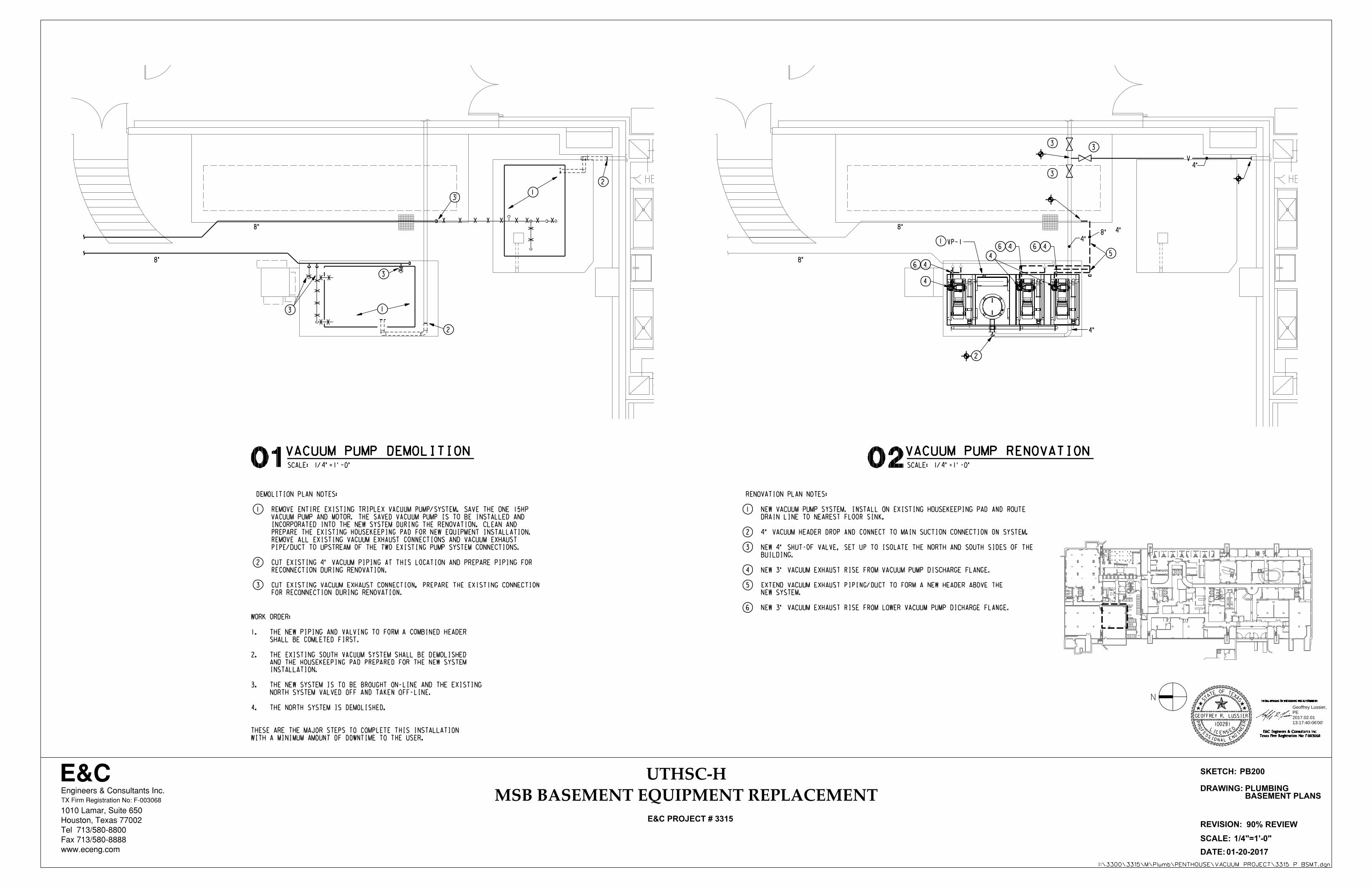
VACUUM PUMP DEMOLITION
SCALE: 1/4"=1'-0"
VACUUM PUMP RENOVATION02
4"
4"
2
4
5
VP-11
1
2
1
2
PB200
BASEMENT PLANSPLUMBING
8"
8"
X X X X X X X X X
XX
X
X
XX
XX
X
XX
X
MSB BASEMENT EQUIPMENT REPLACEMENT
3
3
3
V
8"
8"
8"
4
6
46
4
46
4"
FOR RECONNECTION DURING RENOVATION.
3 CUT EXISTING VACUUM EXHAUST CONNECTION, PREPARE THE EXISTING CONNECTION
RECONNECTION DURING RENOVATION.
2 CUT EXISTING 4" VACUUM PIPING AT THIS LOCATION AND PREPARE PIPING FOR
PIPE/DUCT TO UPSTREAM OF THE TWO EXISTING PUMP SYSTEM CONNECTIONS.
REMOVE ALL EXISTING VACUUM EXHAUST CONNECTIONS AND VACUUM EXHAUST
PREPARE THE EXISTING HOUSEKEEPING PAD FOR NEW EQUIPMENT INSTALLATION.
INCORPORATED INTO THE NEW SYSTEM DURING THE RENOVATION. CLEAN AND
VACUUM PUMP AND MOTOR. THE SAVED VACUUM PUMP IS TO BE INSTALLED AND
1 REMOVE ENTIRE EXISTING TRIPLEX VACUUM PUMP/SYSTEM. SAVE THE ONE 15HP
DEMOLITION PLAN NOTES:
4"
3
33
6 NEW 3" VACUUM EXHAUST RISE FROM LOWER VACUUM PUMP DICHARGE FLANGE.
NEW SYSTEM.
5 EXTEND VACUUM EXHAUST PIPING/DUCT TO FORM A NEW HEADER ABOVE THE
4 NEW 3" VACUUM EXHAUST RISE FROM VACUUM PUMP DISCHARGE FLANGE.
BUILDING.
3 NEW 4" SHUT-OF VALVE, SET UP TO ISOLATE THE NORTH AND SOUTH SIDES OF THE
2 4" VACUUM HEADER DROP AND CONNECT TO MAIN SUCTION CONNECTION ON SYSTEM.
DRAIN LINE TO NEAREST FLOOR SINK.
1 NEW VACUUM PUMP SYSTEM. INSTALL ON EXISTING HOUSEKEEPING PAD AND ROUTE
RENOVATION PLAN NOTES:
WITH A MINIMUM AMOUNT OF DOWNTIME TO THE USER.
THESE ARE THE MAJOR STEPS TO COMPLETE THIS INSTALLATION
4. THE NORTH SYSTEM IS DEMOLISHED.
NORTH SYSTEM VALVED OFF AND TAKEN OFF-LINE.
3. THE NEW SYSTEM IS TO BE BROUGHT ON-LINE AND THE EXISTING
INSTALLATION.
AND THE HOUSEKEEPING PAD PREPARED FOR THE NEW SYSTEM
2. THE EXISTING SOUTH VACUUM SYSTEM SHALL BE DEMOLISHED
SHALL BE COMLETED FIRST.
1. THE NEW PIPING AND VALVING TO FORM A COMBINED HEADER
WORK ORDER:
Geoffrey Lussier,PE2017.02.0113:17:40-06'00'
Radius
Radius
Radius
Radius
Radius
Radius
Radius
Radius
Radius
Radius
Radius
Radius
Radius
Radius
Radius
Radius
RadiusRadiusRadiusRadiusRadius
EXH
EXH
EXH
EXH
SKETCH:
DRAWING:
DATE:
REVISION:
E&CEngineers & Consultants Inc.
1010 Lamar, Suite 650
Houston, Texas 77002
Tel 713/580-8800
Fax 713/580-8888
www.eceng.com
TX Firm Registration No: F-003068
SCALE:
01-03-2017
THE SEAL APPEARING ON THIS DRAWING WAS AUTHORIZED BY:
Texas Firm Registration No: F-003068
E&C Engineers & Consultants Inc.
PR
OF
ESSIONAL EN
GI
NE
ER
S
TAT
E OF TEXA
S
GEOFFREY R. LUSSIER
100281LICENSE
D
1
I:\3300\3315\M\Plumb\PENTHOUSE\3315 P BSMT DETAILS.dgn
E&C PROJECT # 3315
MSB BASEMENT EQUIPMENT REPLACEMENT
UTHSC-H
PIPE
PIPE SADDLE OR BLOCKING
RE: SPECIFICATIONS
OF ATTACHMENT TO STRUCTURE
RE: SPECIFICATIONS FOR METHOD
HANGER ROD
CLEVIS HANGER 4"OD AND LARGER
STRAP HANGER 3"OD AND SMALLER
INSULATED PIPE WITH PIPE
SHIELD. RE: SPECIFICATIONS
UNINSULATED PIPE
CLEVIS HANGER 4"OD AND LARGER
STRAP HANGER 3"OD AND SMALLER
OF ATTACHMENT TO STRUCTURE
RE: SPECIFICATIONS FOR METHOD
VIBRATION ISOLATORS WHERE
VIBRATION ISOLATORS, WHERE
HANGER ROD,
REQUIRED, RE: SPECIFICATIONS
REQUIRED, RE: SPECIFICATIONS
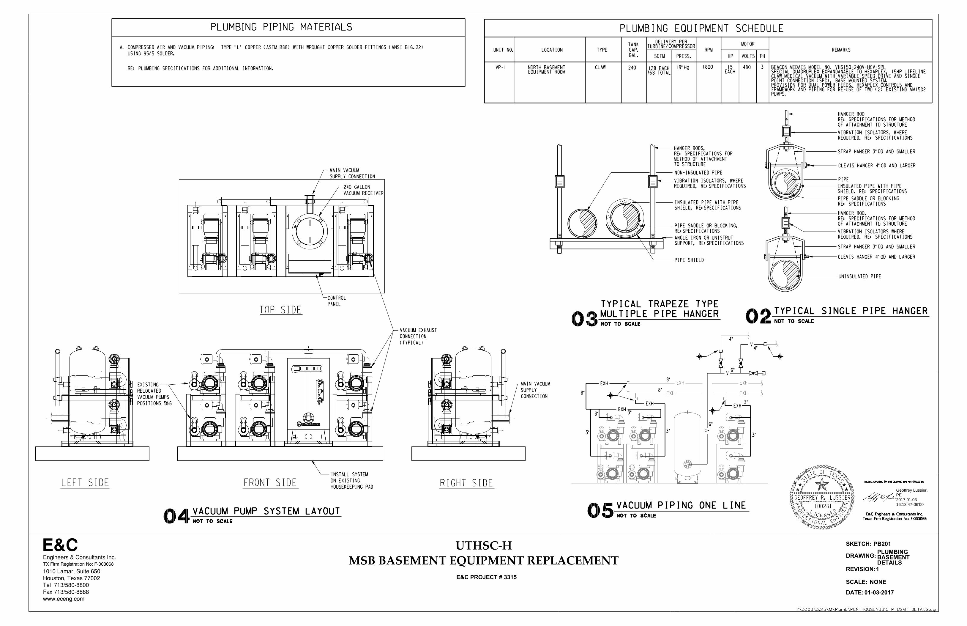
02NOT TO SCALE
TYPICAL SINGLE PIPE HANGER
PLUMBING PIPING MATERIALS
480 3
SCFM
TURBINE/COMPRESSORDELIVERY PER
PLUMBING EQUIPMENT SCHEDULE
A.
RE: PLUMBING SPECIFICATIONS FOR ADDITIONAL INFORMATION.
USING 95/5 SOLDER.
COMPRESSED AIR AND VACUUM PIPING: TYPE "L" COPPER (ASTM B88) WITH WROUGHT COPPER SOLDER FITTINGS (ANSI B16.22) TYPE CAP. RPMLOCATION REMARKS
TANK
GAL. PRESS. HP VOLTS PH
MOTOR
UNIT NO.
VP-1 19"Hg 1800EQUIPMENT ROOMNORTH BASEMENT CLAW 240
768 TOTAL128 EACH
NOT TO SCALE04VACUUM PUMP SYSTEM LAYOUT
PB201
NONE
DETAILSBASEMENTPLUMBING
RIGHT SIDEFRONT SIDELEFT SIDE
TOP SIDE
03NOT TO SCALE
TYPICAL TRAPEZE TYPE
MULTIPLE PIPE HANGER
VIBRATION ISOLATORS, WHERE
NON-INSULATED PIPE
INSULATED PIPE WITH PIPE
SHIELD, RE:SPECIFICATIONS
ANGLE IRON OR UNISTRUT
SUPPORT, RE:SPECIFICATIONS
PIPE SADDLE OR BLOCKING,
RE:SPECIFICATIONS
PIPE SHIELD
REQUIRED, RE:SPECIFICATIONS
HANGER RODS,
RE: SPECIFICATIONS FOR
METHOD OF ATTACHMENT
TO STRUCTURE
(TYPICAL)
CONNECTION
VACUUM EXHAUST
CONNECTION
SUPPLY
MAIN VACUUM
SUPPLY CONNECTION
MAIN VACUUM
EACH15
PUMPS.FRAMEWORK AND PIPING FOR RE-USE OF TWO (2) EXISTING MM1502PROVISION FOR DUAL POWER FEEDS, HEXAPLEX CONTROLS AND POINT CONNECTION (SPC), BASE MOUNTED SYSTEM.CLAW MEDICAL VACUUM WITH VARIABLE SPEED DRIVE AND SINGLESPECIAL QUADRUPLEX EXPANDANABLE TO HEXAPLEX, 15HP LIFELINEBEACON MEDAES MODEL NO. VHS15Q-240V-HCV-SPL
VACUUM RECEIVER
240 GALLON
PANEL
CONTROL
POSITIONS 5&6
VACUUM PUMPS
RELOCATED
EXISTING
HOUSEKEEPING PAD
ON EXISTING
INSTALL SYSTEM
NOT TO SCALE05VACUUM PIPING ONE LINE
4"
4"
6"
6"
V
V
8"
8"8"
3"
3" 3"
3"
V
EXH
EXHEXH
3"
3"
EXH
Geoffrey Lussier,PE2017.01.0316:13:47-06'00'

HB HB
CHEM STO CHEM STO CHEM STO
double 55g
drum storage
double 55g
drum storage
HBFS
FS
FS
HB
FS
FS
BAND
SAW
CHEM
STO
HOOD
HB
CHEST
FREEZER
FD
CHEM
STO55g
DRUM
STO
55g
DRUM
STO
FS
FD
HB
FS FS FS
FS
HB
FS
FS FS
HB
FS
HB
FS
F.D.F.D.
FS
FS
FS
FS
FS
REF
FS
DW
MSB BASEMENT EQUIPMENT REPLACEMENT
BDHE BDHE
SKETCH:
DRAWING:
DATE:
REVISION:
E&CEngineers & Consultants Inc.
1010 Lamar, Suite 650
Houston, Texas 77002
Tel 713/580-8800
Fax 713/580-8888
www.eceng.com
TX Firm Registration No: F-003068
SCALE:
01-03-2017
THE SEAL APPEARING ON THIS DRAWING WAS AUTHORIZED BY:
Texas Firm Registration No: F-003068
E&C Engineers & Consultants Inc.
PR
OF
ESSIONAL EN
GI
NE
ER
S
TAT
E OF TEXA
S
LICENSE
D
97304
LARKIN GENTRY
1
I:\3300\3315\M\Elec\3315 E BSMT.dgn
E&C PROJECT # 3315
N
1/4"=1'-0"
UTHSC-H
MSB BASEMENT EQUIPMENT REPLACEMENT
01SCALE: 1/4"=1'-0"
VACUUM PUMP DEMOLITION
SCALE: 1/4"=1'-0"
VACUUM PUMP RENOVATION02
1
1
EB200
BASEMENT PLANSELECTRICAL
WORK
SCOPE OF
2
SERVES BOTH TRIPLEX VACUUM PUMPS TO BE REMOVED.
2 RACK MOUNTED EXISTING DISTRIBUTION PANEL BDHE TO REMAIN. PANEL
ALTERATION PLAN FOR ADDITIONAL INFORMATION.
BE REUSED FOR NEW BRANCH CIRCUIT TO NEW VACUUM PUMP. RE:
IS SERVED FROM DISTRIBUTION PANEL BDHE. CONDUIT HANGERS MAY
1 REMOVE BRANCH CIRCUIT TO TRIPLEX VACUUM PUMP COMPLETELY. PUMP
DEMOLITION PLAN NOTES:
12
34
FEED B".
PANEL TO VACUUM PUMP AS REQUIRED. RE-LABEL BREAKER "CLINICAL VACUUM
WITH NEW 90A TRIP RATING PLUG. EXTEND WIRE AND CONDUIT FROM
BREAKER TO REMAIN. REMOVE 125A TRIP RATING PLUG AND REPLACE
REMOVED. BREAKER IS LABELED "CLINICAL VACUUM NORTH". EXISTING
4 EXISTING CIRCUIT AND BREAKER FOR EXISTING VACUUM PUMP SYSTEM TO BE
FEED A".
PANEL TO VACUUM PUMP AS REQUIRED. RE-LABEL BREAKER "CLINICAL VACUUM
WITH NEW 90A TRIP RATING PLUG. EXTEND WIRE AND CONDUIT FROM
BREAKER TO REMAIN. REMOVE 125A TRIP RATING PLUG AND REPLACE
REMOVED. BREAKER IS LABELED "CLINICAL VACUUM SOUTH". EXISTING
3 EXISTING CIRCUIT AND BREAKER FOR EXISTING VACUUM PUMP SYSTEM TO BE
ELECTRICAL CONNECTIONS AS REQUIRED.
FOR THREE PUMPS AND A SECOND FOR THE OTHER THREE PUMPS. MAKE
AND CONTROLS. CONTROL PANEL SHALL HAVE TWO ELECTRICAL FEEDS. ONE FEED
2 NEW VACUUM PUMP CONTROL PANEL WITH INTEGRAL DISCONNECTS, OVERLOADS,
1 NEW VACUUM PUMP SYSTEM. RE: PLUMBING PLANS FOR MORE INFORMATION.
RENOVATION PLAN NOTES:
1-1/4"C3#3,#8G,BDHE-7
1-1/4"C3#3,#8G,BDHE-8
LOAD REDUCED ON PANEL BDHE = -78A
SIX (5) 15HP MOTORS ADDED = 126A
SIX (6) 25HP MOTORS REMOVED = -204A
LOAD ANALYSIS:
Larkin GentryHouston, TX
713.580.88332017.01.03
10:28:26-06'00'
Vacuum Pump Replacement Page 1 UT Medical School Building (MSB) TABLE OF CONTENTS Houston, TX
E&C Engineers & Consultants TOC - 1
E&C No. 3315.00
TABLE OF CONTENTS
Section No. Title
DIVISION 22 – PLUMBING
22 62 21 Laboratory Vacuum pump Systems (Rotary Claw)
DIVISION 23 – MECHANICAL
23 00 00 Basic Mechanical Requirements 23 05 29 Sleeves, Flashings, Supports and Anchors
DIVISION 26 – ELECTRICAL
26 00 00 Electrical
END OF TABLE OF CONTENTS
E&C Engineers & Consultants, Inc. TX Firm Registration No: F-003068 Date: 1-03-2017 Engineer of Record: Larkin Gentry State: Texas License no: 97304
E&C Engineers & Consultants, Inc. TX Firm Registration No: F-003068 Date: 1-03-2017 Engineer of Record: Geoffrey Lussier State: Texas License no: 100281
LI C E N
ESD
97304
LARKIN GENTRY
THE SEAL APPEARING ON THIS DRAWING WAS AUTHORIZED BY:
E&C Engineers & Consultants Inc.Texas Firm Registration No: F-003068
STATE OF TEXA
S
PROF
ESSIONAL EN
GIN
EER
Larkin GentryHouston, TX
713.580.88332017.01.03
10:46:04-06'00'
LI C E N
ESD
100281
GEOFFREY R. LUSSIER
THE SEAL APPEARING ON THIS DRAWING WAS AUTHORIZED BY:
E&C Engineers & Consultants Inc.Texas Firm Registration No: F-003068
STATE OF TEXA
S
PROF
ESSIONAL EN
GIN
EER
Geoffrey Lussier,PE2017.01.0316:07:24-06'00'

Vacuum Pump Replacement Section 22 62 21, Page 1
UT Medical School Building (MSB) LABORATORY VACUUM PUMP SYSTEMS
Houston, TX
E&C Engineers & Consultants Inc. 22 62 21 - 1
E&C No. 3315.00
SECTION 22 62 21 – LABORATORY VACUUM PUMP SYSTEMS (ROTARY CLAW)
PART 1 - GENERAL
1.01 RELATED DOCUMENTS
A. Drawings and general provisions of the Contract, including General Conditions and
Division 01 Specification Sections, apply to this Section.
B. Specifications throughout all Divisions of the Project Manual are directly applicable to this
Section, and this Section is directly applicable to them.
1.02 SUMMARY
A. This section includes the furnishing of all labor and materials necessary for complete
installation, cleaning, testing, start-up and certification of laboratory vacuum pump system,
including; pumps, receiver tank, controls, interconnecting piping, local alarms, remote alarm
contacts, valves, supports, and all related accessories.
1.03 REFERENCE STANDARDS
A. The latest published edition of a reference shall be applicable to this Project unless identified
by a specific edition date.
B. All reference amendments adopted prior to the effective date of this Contract shall be
applicable to this Project.
C. All materials, installation and workmanship shall comply with the applicable requirements and
standards addressed within the following references:
1. NFPA 99 Standard for Health Care Facilities.
2. NFPA 70 National Electrical Code.
1.04 QUALIFICATIONS
A. General: Companies specializing in manufacturing, installing, testing, certifying and servicing
the products and systems specified in this section shall have minimum five years documented
experience and be certified as required by the Texas Department of Health and NFPA 99.
B. Manufacturers: Firms regularly engaged in manufacture of medical vacuum systems
equipment and products, of types, materials, and sizes required, whose products have been
in satisfactory use in similar service for not less than 5 years. References may be required.
C. Equipment Supplier: The medical vacuum systems equipment supplier shall provide the
services of a manufacturer authorized product specialist to periodically coordinate with the
installing Contractor during initial installation of the pipeline systems and have a service
organization located within 50 miles of the project Site to provide ongoing service support to
UT Health Science Center - Houston after project completion.

Vacuum Pump Replacement Section 22 62 21, Page 2
UT Medical School Building (MSB) LABORATORY VACUUM PUMP SYSTEMS
Houston, TX
E&C Engineers & Consultants Inc. 22 62 21 - 2
E&C No. 3315.00
D. Installer: Firm with at least 5 years of successful installation experience on projects with
medical gas systems work similar to that required for project. All installations of the medical
vacuum piping systems shall be done only by, or under the direct supervision of a holder of a
master plumber license or a journeyman plumber license with a medical gas piping installation
endorsement issued by the Texas State Board of Plumbing Examiners. All installers of
medical gas system components must be qualified in accordance with the requirements of
NFPA 99 and ASSE 6010, Medical Gas Systems Installers Professional Qualifications
Standard. In addition, all brazers of medical gas system piping must be qualified in
accordance with the requirements of either Section IX, Welding and Brazing Requirements of
the ASME Boiler and Pressure Vessel Code, or AWS B2.2, Standard for Brazing Procedure
and Performance Qualification.
E. System Verification Testing Agency: Testing shall be conducted by a party technically
competent and experienced in the field of medical gas and vacuum pipeline testing and
meeting the requirements of ANSI/ASSE Standard 6030, Medical Gas Verifiers Professional
Qualifications Standard. Quality control standards of testing agency shall be in strict
accordance with American National Standards Institute (ANSI) Q-91. Firm shall be regularly
engaged in the testing and certification of similar facilities with a minimum of 5 years of
experience.
1.05 QUALITY ASSURANCE
A. All materials, equipment, installation, testing and certification shall be in strict accordance with
NFPA 99 for Level 1 Medical–Surgical Vacuum.
B. Manufacturer’s name, address and contact information shall be permanently labeled on
equipment.
C. Maintain one copy of each Contract Document on Site.
D. Prior to any installation Work, the installer of medical vacuum piping shall provide and
maintain documentation on the job Site for the qualification of brazing procedures and
individual brazers as required by NFPA 99.
1.06 SUBMITTALS
A. General:
1. All submitted data shall be specific to this project and identified as such. Generic
submittal data will not be accepted.
B. Product Data:
1. Manufacturers descriptive literature, illustrations and installation instructions for all
components included within this project indicating compliance with applicable referenced
standards, size, dimensions, model number, electrical characteristics, support and
connection requirements.
C. Shop Drawings:
1. Wiring diagrams for laboratory vacuum source equipment system. Differentiate between
manufacturer-installed and field-installed wiring.
D. Record Documents:
Vacuum Pump Replacement Section 22 62 21, Page 3
UT Medical School Building (MSB) LABORATORY VACUUM PUMP SYSTEMS
Houston, TX
E&C Engineers & Consultants Inc. 22 62 21 - 3
E&C No. 3315.00
1. Record actual locations of equipment, piping, valves and controls.
2. Provide record of test procedures and the results of all tests indicating room and area
designations, dates of the tests, and names of persons conducting the tests.
3. Brazer Certificates: Installation Contractor shall present written documentation (less than
1 year old) from a recognized agency trained in administering and testing brazing
techniques as per AWS B2.2 or ASME Section IX, certifying that all brazers have been
thoroughly trained and tested in the complete installation of medical gas systems.
4. Inspection and Test Reports: Furnish documentation that all installer inspections and
tests required by NFPA 99 for Level 1 Medical–Surgical Vacuum have been performed.
Identify test type, procedure and results.
5. Independent Third Party System Verification Testing Agency Reports and Certification:
Documentation verifying that completed systems have been installed, tested, purged, and
analyzed in accordance with the requirements of referenced standards and Contract
Documents. Provide copy of agency’s written Q-91 standards.
6. Statement of Warranty: Provide equipment manufacturers Statement of Warranty for all
furnished equipment and components. Warranty shall specifically indicate project by
name and date of equipment start-up.
7. Provide full written description of manufacturer’s warranty.
E. Operation and Maintenance Data:
1. Operation Data: Include manufacturer’s installation and operating instructions.
2. Maintenance Data: Servicing requirements, inspection data, preventative maintenance
schedule, exploded assembly views, replacement part numbers and availability, location
and contact numbers of service depot.
1.07 DELIVERY, STORAGE AND HANDLING
A. Equipment and components shall arrive on-Site properly protected and undamaged with
containers, packaging and labels intact.
B. Each pipe and tank opening shall be delivered plugged or capped by the manufacturer and
kept sealed until prepared for installation.
C. Loose fittings, valves, gauges and other components shall be delivered sealed, labeled, and
kept sealed until installation.
D. Store, handle and protect materials and equipment in accordance with Manufacturer's
recommendations.
E. Provide equipment and personnel necessary to handle equipment and components by
methods to prevent damage to products or packaging. Provide additional protection during
handling as necessary to prevent breaking scraping, marring, or otherwise damaging products
or surrounding areas.
F. Lift heavy components only at designated lifting points.
Vacuum Pump Replacement Section 22 62 21, Page 4
UT Medical School Building (MSB) LABORATORY VACUUM PUMP SYSTEMS
Houston, TX
E&C Engineers & Consultants Inc. 22 62 21 - 4
E&C No. 3315.00
G. Protect all equipment and components that are to be installed within this project from theft,
vandalism, and exposure to rain, freezing temperatures and direct sunlight.
H. Protect installed equipment and components from damage and prevent use.
1.08 SCHEDULING
A. Schedule Work to ensure installation is complete, tested and certified prior to Substantial
Completion.
1.09 WARRANTY
A. Manufacturer shall warrant furnished equipment and components to be free of defects in
material and workmanship under normal use for a period of thirty-six (36) months from date of
start-up.
PART 2 - PRODUCTS
2.01 GENERAL
A. All materials shall meet or exceed all applicable referenced standards, federal, state and local
requirements, and conform to codes and ordinances of authorities having jurisdiction.
B. Furnish a central vacuum system consisting of dry rotary claw type vacuum pumps mounted
on skids with automatic lead/lag electrical controls and an ASME coded receiver. The
complete vacuum system including electrical controls shall be designed, assembled, and
factory tested by the vacuum pump manufacturer. Vacuum systems that are designed and/or
fabricated by sources other than the vacuum pump manufacturer shall not be accepted. The
vacuum system shall meet or exceed the requirements listed in the latest edition of NFPA
99C.
C. The Contractor shall ascertain for himself the space and access available for the installation
of a factory assembled packaged unit and, as an option, may furnish factory assembled
modular units and interconnect the various components in place at the Site in lieu of providing
a factory assembled packaged unit. However, all components shall be compatible and be
tested as a complete system prior to shipment, and be furnished by a single source
manufacturer. All electrical services and interconnecting equipment wiring and piping must be
provided for within this Contractor’s bid.
D. Each vacuum pump shall have a factory piped intake to the receiver with NFPA 99 compliant
integral flex connector, isolation valve, and check valve.
E. An automatic means shall be provided to prevent backflow from any on-cycle vacuum pumps
through any off-cycle vacuum pumps.
F. A shutoff valve and check valve shall isolate each vacuum pump from the centrally piped
system and other vacuum pumps for maintenance or repair without loss of vacuum in the
system.
G. Piping shall be arranged to permit service and a continuous supply of medical–surgical
vacuum in the event of a single fault failure.
H. Refer to the Plumbing Fixture Schedule on Contract Drawings for required quantity of pumps,
capacities, receiver size, component skid arrangement and electrical characteristics.

Vacuum Pump Replacement Section 22 62 21, Page 5
UT Medical School Building (MSB) LABORATORY VACUUM PUMP SYSTEMS
Houston, TX
E&C Engineers & Consultants Inc. 22 62 21 - 5
E&C No. 3315.00
I. Laboratory vacuum pump system design must be equal in all aspects to the rotary claw Mink
MM Series system manufactured by Busch, Inc. and packaged by Beacon Medaes, Inc.
2.02 VACUUM PUMPS
A. Each vacuum pump shall be direct-driven through a shaft coupling by a NEMA C-face,
footless, TEFC electric motor wired for operation on a 208-230 or 460 volt, 60 hertz, 3 phase
power supply. Belt drives shall not be permitted.
B. Each vacuum pump shall be air-cooled and have absolutely no water requirements.
C. Each vacuum pump shall be capable of running continuously at an (ultimate) vacuum of 24"
Hg (sea level).
D. Each vacuum pump shall be dry-running, featuring two claw-type, non-contacting rotors and
shall not require any sealing fluid, assuring virtually maintenance-free operation. Each
vacuum pump shall require an oil change in the gearbox only, at approximately 20,000
operating hour intervals. Each vacuum pump shall include a built in, anti-suck-back valve
mounted at the pump inlet and shall be equipped with a 5 micron inlet filter for removal of
particulates.
2.03 VACUUM RECEIVER
A. A receiver tank shall be provided to add capacity to the vacuum piping system in order to
reduce frequent cycling of a pump operating on a vacuum switch. Intake piping from each
vacuum pump shall be manifolded and connected to the receiver tank at the factory in order
for the receiver to function as a dropout tank to help prevent carry-over of solids or liquids into
the pumps.
B. The receiver shall be ASME Code stamped and shall be rated for full vacuum to 150 psig
working pressure.
C. Tank interior shall be epoxy coated for corrosion resistance.
D. The receiver shall be provided with a sight/level gauge, a manual drain and have a three valve
bypass system to allow for draining of the receiver without interrupting the vacuum service.
E. Receiver shall have capacity and physical dimensions as scheduled on Contract Drawings.
2.04 CONTROL SYSTEM
A. The vacuum system shall be equipped with a NFPA 99C compliant electrical control center.
This control center shall alternate the vacuum pumps on a demand basis when the lead
vacuum pump has met vacuum demand and on an additional timed basis to provide
approximate equal run time for each vacuum pump in use.
B. All vacuum pumps shall be controlled in a cascading lead-lag sequence when operating in the
auto mode. The control system shall be programmed to minimize motor starts per hour per
NEMA standards.
Vacuum Pump Replacement Section 22 62 21, Page 6
UT Medical School Building (MSB) LABORATORY VACUUM PUMP SYSTEMS
Houston, TX
E&C Engineers & Consultants Inc. 22 62 21 - 6
E&C No. 3315.00
C. The control system shall contain IEC magnetic motor starters with solid state overloads; low
voltage(24V) control transformers with primary and secondary fusing; Hand-Off-Auto mode
selector switches with integral pump run indicating lights; reserve-pump-in-use visual and
audible alarms with silence and reset push buttons; dry contacts for remote indication of
alarm; hour meters; a programmable controller to provide automatic alternation of pumps,
minimum run timers, and vacuum control with adjustable set-points through a data interface; a
main disconnecting means and power distribution block for dual point power connection; an
equipment ground bus; IEC style terminal blocks; circuit breaker disconnects for each motor;
single variable speed drive, all housed in a NEMA 4/12 enclosure.
D. The entire control center assembly shall be UL508 listed.
E. Control circuits shall be arranged in such a manner that the shutdown of one pump does not
interrupt the operation of another pump.
F. The touch screen controls shall have a master screen that is a 5.7” high resolution LCD, the
individual unit screens are 3.5” high resolution LCD. There is built in Ethernet connectivity
with an embedded web page. The master screen provides: Vacuum level, VSD motor
speed, trends and graphs for multiple time periods, service times and history, alarm and
shutdown logs as well as all the system setting access.
2.05 LABORATORY VACUUM PUMP SYSTEM PIPING
A. Interconnecting piping within the medical vacuum pump system and all exhaust piping shall
be Type "K" or “L” hard-drawn seamless copper, either ASTM B 819 medical gas tube or
ASTM B 88 water tube.
B. Turns, offsets, and other changes in direction shall be made with brazed wrought copper
capillary fittings complying with ANSI B16.22, Wrought Copper and Copper Alloy Solder-Joint
Fittings; or brazed fittings complying with MSS SP-73, Brazed Joints for Wrought and Cast
Copper Alloy Solder Joint Pressure Fittings. Cast copper alloy fittings shall not be permitted.
C. Brazed joints shall be made using a brazing alloy that exhibits a melting temperature in
excess of 538°C (1000°F). Copper-to-copper joints shall be brazed using a copper–
phosphorus or copper–phosphorus–silver brazing filler metal (BCuP series) without flux. Flux
shall only be used when brazing dissimilar metals such as copper and bronze or brass, using
a silver (BAg series) brazing filler metal. Brazing alloy comply with ANSI/AWS A.5.8,
Specification for Brazing Filler Metal.
D. Threaded joints in medical vacuum piping shall be limited to connections to pressure/vacuum
indicators, alarm devices, and connections to equipment. All threads shall be tapered pipe
threads complying with ANSI B1.20.1, Pipe Threads, General Purpose and be made up with
polytetrafluoroethylene (such as Teflon™) tape or other thread sealant recommended for
oxygen service, with the sealant applied to the male threads only. Where threaded nipples are
required, these shall be I.P.S. brass.
E. Mechanically formed, drilled and extruded tee-branch connections are not permitted.
F. Couplings and fittings incorporating an o-ring seal are not permitted.
G. Roll-grooved joints are not permitted.
H. Straight-threaded connections, including unions, flared and compression-type connections,
are not permitted.
Vacuum Pump Replacement Section 22 62 21, Page 7
UT Medical School Building (MSB) LABORATORY VACUUM PUMP SYSTEMS
Houston, TX
E&C Engineers & Consultants Inc. 22 62 21 - 7
E&C No. 3315.00
I. Seal fluid supply lines shall be Aeroquip MatchMate Plus or equal high-pressure hose with
crimp on fittings. Rigid steel pipe with screwed fittings is not acceptable because of potential
seal fluid leaks from pipe joints.
2.06 LABORATORY VACUUM SHUT-OFF VALVES
A. Shut-off valves shall be full port, double seal, ball-type three piece design, designed for
vacuum to 29 inches Hg and working pressures up to 600 WOG with bronze/brass body,
blow-out proof stem and chrome plated brass ball and be serviceable in the line. Valve body
shall have Teflon™ (TFE) material ball seat and stem seals. Seats/seals, lubricants and valve
material shall be compatible with medical oxygen, nitrous oxide, compressed air, carbon
dioxide, nitrogen and mixtures thereof at continuous pressure up to 600 psig and up to 100
degrees Fahrenheit.
B. Valve shall be provided with and operated by a lever-type handle requiring only a quarter turn
from a fully open position to a fully closed position.
2.07 LABORATORY VACUUM CHECK VALVES
A. Check valves shall be center guided, self-aligning, spring loaded ball type check with brass
body, Teflon seat, straight-through flow, 400 psi WOG minimum working pressure, having
vibration free, silent operation.
B. Check valves shall be 100% leak tested and comply with NFPA 99.
2.08 ACCESSORIES
A. Flexible connectors for the inlet and discharge connections, and one set of vibration pads
shall be included with the vacuum system.
PART 3 - EXECUTION
3.01 INSTALLATION
A. Installation shall meet or exceed all applicable federal, state and local requirements,
referenced standards and conform to codes and ordinances of authorities having jurisdiction.
B. All installation shall be in accordance with manufacturer’s published recommendations.
C. Install all system components in complete compliance with referenced standards and
manufacturer’s published instructions.
D. Locate equipment with adequate access space for service. Provide no less than minimum as
recommended by manufacturer.
E. Provide minimum 4” thick reinforced concrete pad with chamfered corners beneath floor
mounted equipment. Pads shall extend minimum of 4” on all sides beyond the limits of the
mounted equipment unless otherwise noted.
F. Anti-vibration mountings shall be installed for vacuum pumps as required by equipment
dynamics or location and in accordance with the manufacturer’s recommendations.
G. Flexible connectors shall be used to connect the vacuum pumps with their intake and outlet
piping.
Vacuum Pump Replacement Section 22 62 21, Page 8
UT Medical School Building (MSB) LABORATORY VACUUM PUMP SYSTEMS
Houston, TX
E&C Engineers & Consultants Inc. 22 62 21 - 8
E&C No. 3315.00
H. Vacuum piping from building distribution system shall connect to receiver tank inlet prior to
flowing into pumps.
I. Locate laboratory vacuum pumps exhaust in a manner and location that will minimize the
hazards of noise and contamination to the facility and its environment. The exhaust shall
terminate outdoors, at least 25 feet from any door, window, air intake, or other openings in the
building; at least 3 feet above all air intakes and where prevailing winds, adjacent buildings, or
other influences cannot divert the exhaust into occupied areas or disperse the exhaust.
J. The exhaust terminal shall be turned down and screened with non-corroding material to
protect against the entry of vermin, debris, or precipitation.
K. The exhaust piping shall be free of dips and loops that might trap condensate or oil. Where
such low points are unavoidable, a drip leg and valved drain shall be installed. Vacuum
exhausts from multiple pumps shall be joined together to one common exhaust. The common
exhaust shall be sized to minimize back-pressure in accordance with the pump
manufacturer’s recommendations.
L. Each pump shall be isolated by a ball valve and a check valve to prevent flow of exhaust air
into the room when pumps are removed for service.
M. Vacuum indicators shall be readable from a standing position.
N. Provide low voltage wiring from vacuum source equipment to master alarm annunciators as
required by NFPA 99. All low voltage wiring shall be routed within conduit.
O. Coordinate with Electrical Contractor to insure that emergency electrical service is provided
for the vacuum source equipment conforming to the requirements of the essential electrical
system as described in NFPA 99.
P. Remove all dirt, dust, construction debris and all other foreign materials from installed
equipment and components. Equipment finishes shall be free from all rust, scratches, dents,
etc. Contractor shall be responsible for all cleaning and re-finishing required to provide Owner
with equipment that is in factory-new condition at Substantial Completion of the project. All
labels shall be clean and legible.
3.02 TESTING AND INSPECTION
A. Inspection and testing shall be performed on medical–surgical vacuum source system before
being put into service to assure the facility, by a documented procedure, that all applicable
provisions of NFPA 99 have been adhered to, that the system is functioning properly, and
system integrity has been achieved or maintained.
B. System verification tests shall be performed only after all installer performed tests, have been
completed. Equipment Vendor or installing Contractor shall not perform system verification,
final testing or certification.
C. It shall be the responsibility of the Third Party Medical Gas System Verification Testing
Agency to make periodic job Site visits to assure all requirements of this specification and
NFPA 99 are strictly adhered to.
D. Certification shall clearly state that the system is approved for laboratory use and meets all
requirements of NFPA-99 inclusive of all referenced and/or related documents. Any
exceptions or limitations shall be clearly stated on the same certification document.
Vacuum Pump Replacement Section 22 62 21, Page 9
UT Medical School Building (MSB) LABORATORY VACUUM PUMP SYSTEMS
Houston, TX
E&C Engineers & Consultants Inc. 22 62 21 - 9
E&C No. 3315.00
3.03 VENDOR SUPERVISION
A. An authorized representative of the equipment manufacturer shall periodically check with the
installing Contractor during initial installation of the laboratory vacuum pump system and shall
assist the Contractor in final checking to make certain that all components are operating as
recommended by the manufacturer, as specified, and in accordance with NFPA 99. The
equipment manufacturer's representative shall provide a minimum of 4 hours instruction to UT
Health Science Center - Houston personnel in the use, operation and maintenance of the
system.
END OF SECTION 22 62 21

Vacuum Pump Replacement Section 23 00 00 Page 1 UT Medical School Building (MSB) BASIC MECHANICAL REQUIREMENTS Houston, TX
E&C Engineers & Consultants 23 00 00 - 1 E&C No. 3315.00
SECTION 23 00 00
BASIC MECHANICAL REQUIREMENTS
PART 1 GENERAL
1.01 SECTION INCLUDES
A. Basic Mechanical Requirements specifically applicable to Division 23 Sections.
1.02 RELATED DOCUMENTS:
A. All work covered by this Section of these Specifications shall be accomplished in accordance with all applicable provisions of the Contract Documents and any addenda or directives which may be issued herewith, or otherwise.
1.03 GENERAL:
A. The Contractor shall execute all work hereinafter specified or indicated on accompanying Drawings. Contractor shall provide all equipment necessary and usually furnished in connection with such work and systems whether or not mentioned specifically herein or on the Drawings.
B. The Contractor shall be responsible for fitting his material and apparatus into the building and shall carefully lay out his work at the site to conform to the structural conditions, to avoid all obstructions, to conform to the details of the installation and thereby to provide an integrated satisfactory operating installation.
C. The Mechanical, Electrical, and Plumbing associated Drawings are necessarily diagrammatic by their nature, and are not intended to show every connection in detail or every pipe or conduit in its exact location. These details are subject to the requirements of standards referenced elsewhere in these specifications, and structural and architectural conditions. The Contractor shall carefully investigate structural and finish conditions and shall coordinate the separate trades in order to avoid interference between the various phases of work. Work shall be organized and laid out so that it will be concealed in furred chases and suspended ceilings, etc., in finished portions of the building, unless specifically noted to be exposed. All exposed work shall be installed parallel or perpendicular to the lines of the building unless otherwise noted.
D. When the mechanical and electrical Drawings do not give exact details as to the elevation of pipe, conduit and ducts, the Contractor shall physically arrange the systems to fit in the space available at the elevations intended with proper grades for the functioning of the system involved. Piping, exposed conduit and the duct systems are generally intended to be installed true and square to the building construction, and located as high as possible against the structure in a neat and workmanlike manner. The Drawings do not show all required offsets, control lines, pilot lines and other location details. Work shall be concealed in all finished areas.
1.04 DEFINITIONS: (Note: These definitions are included here to clarify the direction and intention of
this specification. The list given here is not by any means complete. For further clarification as
required, contractor shall contact the designated Owner’s representative.)
A. CONCEALED / EXPOSED: Concealed areas are those areas which cannot be seen by the building occupants. Exposed areas are all areas which are exposed to view by the building occupants, including under counters, inside cabinets and closets, plus all mechanical rooms.
B. General Requirements: The provisions of requirements of other Division 01 sections apply to entire work of contract and, where so indicated, to other elements which are included in project. Basic contract definitions are included in the General Conditions.

Vacuum Pump Replacement Section 23 00 00 Page 2 UT Medical School Building (MSB) BASIC MECHANICAL REQUIREMENTS Houston, TX
E&C Engineers & Consultants 23 00 00 - 2 E&C No. 3315.00
C. Indicated: The term "indicated" is a cross reference to graphic representations, notes or schedules on drawings, to other paragraphs or schedules in the Specifications, and to similar means of recording requirements on contract documents. Where terms such as "shown", "noted", "scheduled", and "specified" are used in lieu of "indicated", it is for the purpose of helping reader locate the cross reference, and no limitation of location is intended except as specifically noted.
D. Directed, requested, etc.: Where not otherwise explained, terms such as "directed", "requested", "authorized", "selected", "approved", "required", "accepted", and "permitted" mean directed by Architect/Engineer", "requested by Architect/Engineer" and similar phrases. However, no such implied meaning will be interpreted to extend Architect's/Engineer's responsibility into Contractor's area of construction supervision and job safety.
E. And/Or: Where "and/or" is used in these Specifications or on the Drawings, it shall mean "that situations exist where either one or both conditions occur or are required and shall not be interpreted to permit an option on the part of the Contractor.
F. Approve: Where used in conjunction with Architect's/Engineer's response to submittals, requests, applications, inquiries, reports and claims by Contractor, the meaning of term "approved" will be held to limitations to Architect's/Engineer's responsibilities and duties as specified in General and Supplementary Conditions. In no case will "approval" by Architect/Engineer be interpreted as a release of Contractor from responsibilities to fulfill requirements of contract documents or to extend Architect's/Engineer's responsibility into Contractor's area of construction supervision and job safety.
G. As required: Where "as required" is used in these Specifications or on the drawings, it shall mean "that situations exist that are not necessarily described in detail or indicated that may cause the contractor certain complications in performing the work described or indicated. These complications entail the normal coordination activities expected of the Contractor where multiple trades are involved and new or existing construction causes deviations to otherwise simplistic approaches to the work to be performed. The term shall not be interpreted to permit an option on the part of the Contractor to achieve the end result."
H. Furnish:
1. The term "furnish" is used to mean "supply and deliver to project site, ready for unloading, unpacking, assemble, installation, and similar operations."
2. Where "furnish" applies to work for which the installation is not otherwise specified, "furnish" in such case shall mean "furnish and install."
I. Install: The term "install" is used to describe operations at project site including "unloading, unpacking, assembly, erection, placing, anchoring, applying, working to dimension, finishing, curing, protecting, cleaning and similar operation."
J. Provide: The term "provide" means "to furnish and install, complete and ready for intended use."
1.05 PERMITS, UTILITY CONNECTIONS AND INSPECTIONS:
A. All work performed on this project is under the authority of the State of Texas, therefore no local construction fees or construction permits will be required except as may be required for new service taps, or new or modified connections to City controlled services. If inspections by City personnel are specifically required by this document, refer to Division 01 for responsibility.
B. Compliance: The Contractor shall comply in every respect with all requirements of National Fire Protection Association, local Fire Department regulations and utility

Vacuum Pump Replacement Section 23 00 00 Page 3 UT Medical School Building (MSB) BASIC MECHANICAL REQUIREMENTS Houston, TX
E&C Engineers & Consultants 23 00 00 - 3 E&C No. 3315.00
company requirements. In no case does this relieve the Contractor of the responsibility of complying with these Specifications and Drawings where specified conditions are of higher quality than the requirements of the above-specified authorities. Where requirements of the Specifications and Drawings are more lenient than the requirements of the above authorities having jurisdiction, the Contractor shall make installations in compliance with the requirements of the above authorities with no extra compensation.
1.06 CONTRACT DOCUMENTS:
A. All dimensional information related to new structures shall be taken from the appropriate Drawings. All dimensional information related to existing facilities shall be taken from actual measurements made by the Contractor on the site.
B. The interrelation of the Specifications, the Drawings, and the schedules are as follows: The Specifications determine the nature and setting of the several materials, the Drawings establish the quantities, dimensions and details, and the schedules give the performance characteristics. If the Contractor requires additional clarification, he shall request it in writing, following the contractually prescribed information flow requirements.
C. Should the Drawings or Specifications conflict within themselves, or with each other, the better quality, or greater size or quantity of work or materials shall be performed or furnished.
1.07 SUBMITTALS
A. Refer to Uniform General Conditions Article 8.
B. Proposed Products List: Include Products specified in the following Sections:
1. Section 23 05 29 - Sleeves, Flashings, Supports and Anchors
2. Section 22 62 21 - Laboratory Vacuum pump Systems (rotary claw)
C. Submit shop drawings and product data grouped to include complete submittals of related systems, products, and accessories in a single submittal.
D. Mark dimensions and values in units to match those specified.
E. Submit Fabrication Drawings whenever (1) equipment proposed varies in physical size and arrangement from that indicated on the Drawings, thus causing rearrangement of equipment space, (2) where tight spaces require extreme coordination between ductwork, piping, conduit, and other equipment, (3) where called for elsewhere in these Specifications; and (4) where specifically requested by the Architect/Engineer. Fabrication Drawings shall be made at no additional charge to the Owner or the Architect/Engineer.
F. All required Fabrication Drawings, except as noted otherwise, shall be prepared at a scale of not less than 1/4" = 1'-0". Fabrication Drawings for ductwork, air handling units, and sections in Mechanical Rooms shall be drawn at a minimum scale of 3/8" = 1'-0". Submit three blueline prints of each Fabrication Drawing to the Architect/Engineer for review. Reproduction and submittal of the Construction Documents is not acceptable. The Architect/Engineer will review the drawing and return one print with comments.
1.08 SUBSTITUTION OF MATERIALS AND EQUIPMENT:
A. Refer to General Conditions for substitution of materials and equipment.
B. General: Within thirty days after the date of contract award or work order, whichever is later, and before purchasing or starting installation of materials or equipment, the Contractor shall submit for review, a complete list of suppliers, contractors and manufacturers for all materials and equipment which will be submitted for incorporation
Vacuum Pump Replacement Section 23 00 00 Page 4 UT Medical School Building (MSB) BASIC MECHANICAL REQUIREMENTS Houston, TX
E&C Engineers & Consultants 23 00 00 - 4 E&C No. 3315.00
into the project. The list shall be arranged in accordance with the organization of the Specifications. This initial list shall include the manufacturer's name and type or catalog number as required to identify the quality of material or equipment proposed. This list will be reviewed by the Engineer and the Owner and will be returned to the Contractor with comments as to which items are acceptable without further submittal data and which items will require detailed submittal data for further review and subsequent approval. The initial list shall be submitted as herein specified. Materials and equipment requiring detailed submittal data shall be submitted with sufficient data to indicate that all requirements of these Specifications have been met and samples shall be furnished when requested. All manufacturer's data used as part of the submittal shall have all inapplicable features crossed out or deleted in a manner that will clearly indicate exactly what is to be furnished.
C. It is not the intent of the Drawings and/or Specifications to limit products to any particular manufacturer nor to discriminate against an "APPROVED EQUAL" product as produced by another manufacturer. Some proprietary products are mentioned to set a definite standard for acceptance and to serve as a reference in comparison with other products. When a manufacturer's name appears in these Specifications, it is not to be construed that the manufacturer is unconditionally acceptable as a provider of equipment for this project. The successful manufacturer or supplier shall meet all of the provisions of the appropriate specification(s).
D. The specified products have been used in preparing the Drawings and Specifications and thus establish minimum qualities with which substitutes must at least equal to be considered acceptable. The burden of proof of equality rests with the Contractor. The decision of the designer is final.
E. When requested by the Architect/Engineer, the Contractor shall provide a sample of the proposed substitute item. In some cases, samples of both the specified item and the proposed item shall be provided for comparison purposes.
F. Timeliness: The burden of timeliness in the complete cycle of submittal data, shop Drawings, and sample processing is on the Contractor. The Contractor shall allow a minimum of six (6) weeks time frame for review of each submission by the office of the design discipline involved after receipt of such submissions by that design discipline. The Contractor is responsible for allowing sufficient time in the construction schedule to cover the aforementioned cycles of data processing, including time for all resubmittal cycles on unacceptable materials, equipment, etc. covered by the data submitted. Construction delays and/or lack of timeliness in the above regard are the responsibility of the Contractor and will not be considered in any request for scheduled construction time extensions and/or additional costs to the Owner.
G. All equipment installed on this project shall have local representation, local factory authorized service, and a local stock of repair parts.
H. Acceptance of materials and equipment will be based on manufacturer's published data and will be tentative subject to the submission of complete shop Drawings indicating compliance with the contract documents and that adequate and acceptable clearances for entry, servicing, and maintenance will exist. Acceptance of materials and equipment under this provision shall not be construed as authorizing any deviations from the Specifications, unless the attention of the Architect/Engineer has been directed in writing to the specific deviations. Data submitted shall not contain unrelated information unless all pertinent information is properly identified.
I. Certification: The Contractor shall carefully examine all data forwarded for approval and shall sign a certificate to the effect that the data has been carefully checked and found to

Vacuum Pump Replacement Section 23 00 00 Page 5 UT Medical School Building (MSB) BASIC MECHANICAL REQUIREMENTS Houston, TX
E&C Engineers & Consultants 23 00 00 - 5 E&C No. 3315.00
be correct with respect to dimensions and available space and that the equipment complies with all requirements of the Specifications.
J. Physical Size of Equipment: Space is critical; therefore, equipment of larger sizes than shown, even though of specified manufacturer, will not be acceptable unless it can be demonstrated that ample space exists for proper installation, operation, and maintenance.
K. Materials and Equipment Lists: Eight (8) copies of the list of materials and equipment, the name of manufacturer, trade name, type, and catalog number shall be submitted to the Architect/Engineer. The lists shall be accompanied by eight (8) sets of pictorial and descriptive data derived from the manufacturers' catalogs, sales literature, or incorporated in the Shop Drawings.
L. Should a substitution be accepted, and should the substitute material prove defective, or otherwise unsatisfactory for the service intended within the guarantee period, this material or equipment shall be replaced with the material or equipment specified at no additional cost to the Owner.
1.09 MATERIALS AND WORKMANSHIP:
A. All materials, unless otherwise specified, shall be new, free from all defects, suitable for the intended use, and of the best quality of their respective kinds. Materials and equipment shall be installed in accordance with the manufacturer's recommendations and the best standard practice for the type of work involved. All work shall be executed by mechanics skilled in their respective trades, and the installations shall provide a neat, precise appearance. Materials and/or equipment damaged in shipment or otherwise damaged prior to installation shall not be repaired at the job site but shall be replaced with new materials and/or equipment.
B. The responsibility for the furnishing of the proper equipment and/or material and seeing that it is installed as intended by the manufacturer, rests entirely upon the Contractor who shall request advice and supervisory assistance from the representative of specific manufacturers during the installation.
1.10 FLAME SPREAD PROPERTIES OF MATERIALS:
A. Materials and adhesives incorporated in this project to be installed within return air plenums shall conform to NFPA Standard 255, "Method of Test of Surface Burning Characteristics of Building Materials" and NFPA 90. The classification shall not exceed a flame spread rating of 25 for all materials, adhesives, finishes, etc., specified for each system, and shall not exceed a smoke developed rating of 50.
1.11 REGULATORY REQUIREMENTS
A. The "Authority Having Jurisdiction" over the project described by these documents is the Owner, as an Agency of the State of Texas. As such, it is required that the installation shall meet the minimum standards prescribed in the latest editions of the following listed codes and standards, which are made a part of these Specifications. All referenced codes and standards shall be those current at the date of issue of the design documents.
B. National Fire Protection Association Standards (NFPA):
1. NFPA No. 13, Sprinkler System, Installation
2. NFPA No. 14, Standpipes and Hose Systems
3. NFPA No. 20, Centrifugal Fire Pumps
4. NFPA No. 37, Stationary Combustion Engines & Gas Turbines

Vacuum Pump Replacement Section 23 00 00 Page 6 UT Medical School Building (MSB) BASIC MECHANICAL REQUIREMENTS Houston, TX
E&C Engineers & Consultants 23 00 00 - 6 E&C No. 3315.00
5. NFPA No. 45, Fire Protection for Laboratories Using Chemicals
6. NFPA No. 51, Welding & Cutting, Oxygen-Fuel Gas Systems
7. NFPA No. 54, Gas Appliances, Piping, National Fuel Gas Code
8. NFPA No. 70, National Electrical Code
9. NFPA No. 72D, Proprietary Signaling Systems
10. NFPA No. 78, Lightning Protection Code
11. NFPA No. 90A, Air Conditioning Systems
12. NFPA No. 91, Blower & Exhaust Systems
13. NFPA No. 99, Health Care Facilities
14. NFPA No. 101, Life Safety Code
15. NFPA No. 200, Series, Building Construction
16. NFPA No. 255, Method of Test of Surface Burning Characteristics of Building Materials
17. NFPA No. 258, Standard Research Test Method for Determining Smoke Generation of Solid Materials
C. American National Standards Institute (ANSI):
1. A40.8, National Plumbing Code
2. B31.1, Power Piping
3. B9.1, Safety Code for Mechanical Refrigeration
D. American Gas Association Publications (AGA): Directory of Approved Gas Appliances and Tested Accessories
E. American Society of Mechanical Engineers (ASME): Boiler and Pressure Vessel Codes
F. Air Conditioning and Refrigeration Institute Standards (ARI): All standards related to refrigeration and air conditioning equipment and piping furnished under these Specifications.
G. Sheet Metal and Air Conditioning Contractors National Association, Inc. (SMACNA): All current editions of applicable manuals and standards (See Sections 23 31 00.UT and 23 33 00.UT).
H. Air Moving and Conditioning Association (AMCA): All current editions of applicable manuals and standards.
I. American Society of Testing Materials (ASTM): All current editions of applicable manuals and standards.
J. American Water Works Association (AWWA): All current editions of applicable manuals and standards.
K. National Electrical Manufacturers' Association (NEMA): All current editions of applicable manuals and standards.
L. City of Houston, Fire Department as may be applicable to construction on this site.
M. International Building Code, (Includes the International Mechanical and International Plumbing Codes)
N. Texas Occupational Safety Act: All applicable safety standards

Vacuum Pump Replacement Section 23 00 00 Page 7 UT Medical School Building (MSB) BASIC MECHANICAL REQUIREMENTS Houston, TX
E&C Engineers & Consultants 23 00 00 - 7 E&C No. 3315.00
O. Occupational Safety and Health Act (OSHA)
P. ADA and ANSI Standards: All work shall be in accord with all regulations and requirements of the Standards and Specifications for Handicapped and Disabled for the Construction of Public Buildings and Facilities in the State of Texas Usable by Physically Handicapped and Disabled persons, ANSI Standards and the requirements of the American Disabilities Act.
Q. Texas State Fire Marshal Rules
R. State Energy Code – ASHRAE 90.1 – 2012.
S. Ventilation Standard – ASHRAE 62.1 – 2012.
T. Refer to Specification Sections hereinafter bound for additional Codes and Standards.
U. All materials and workmanship shall comply with all applicable state and national codes, Specifications, and industry standards. In all cases where Underwriters' Laboratories,
Inc. has established standards for a particular type material, such material shall comply
with these standards. Evidence of compliance shall be the UL "label" or "listing" under Re-Examination Service.
V. The Contract Documents are intended to comply with the aforementioned rules and regulations; however, some discrepancies may occur. Where such discrepancies occur, the Contractor shall immediately notify the Architect/Engineer in writing of said discrepancies and apply for an interpretation. Should the discovery and notification occur after the execution of a contract, any additional work required for compliance with said regulations shall be paid for as covered by Division 01 of these Contract Documents, providing no work of fabrication of materials has been accomplished in a manner of noncompliance. Should the Contractor fabricate and/or install materials and/or workmanship in such a manner that does not comply with the applicable codes, rules and regulations, the Contractor who performed such work shall bear all costs arising in correcting these deficiencies to comply with said rules and regulations.
1.12 GENERAL MATERIALS AND EQUIPMENT REQUIREMENTS:
A. Storage at Site: The Contractor shall not receive material or equipment at the job site until there is suitable space provided to properly protect equipment from rust, drip, humidity, and dust damage.
B. Capacities shall be not less than those indicated but shall be such that no component or system becomes inoperative or is damaged because of startup or other overload conditions.
C. Conformance with Agency Requirements: Where materials or equipment are specified to be approved, listed, tested, or labeled by the Underwriters' Laboratories, Inc., or constructed and/or tested in accordance with the standards of the American Society of Mechanical Engineers or the Air Moving and Conditioning Association, the Contractor shall submit proof that the items furnished under this Section of the Specifications conform to such requirements. The label of the Underwriters Laboratories, Inc., applied to the item will be acceptable as sufficient evidence that the items conform to such requirements. The ASME stamp or the AMCA label will be acceptable as sufficient evidence that the items conform to the respective requirements.
D. Nameplates: Each major component of equipment shall have the manufacturer's name, address, and catalog number on a plate securely attached to the item of equipment. All data on nameplates shall be legible at the time of Final Inspection.
E. Prevention of Rust: Standard factory finish will be acceptable on equipment specified by model number; otherwise, surfaces of ferrous metal shall be given a rust inhibiting
Vacuum Pump Replacement Section 23 00 00 Page 8 UT Medical School Building (MSB) BASIC MECHANICAL REQUIREMENTS Houston, TX
E&C Engineers & Consultants 23 00 00 - 8 E&C No. 3315.00
coating. The treatment shall withstand 200 hours in salt spray fog test, in accordance with Method 6061 of Federal Standard No. 141. Immediately after completion of the test, the specimen shall show no signs of wrinkling or cracking and no signs of rust creepage beyond 1/8" on either side of the scratch mark. Where rust inhibitor coating is specified hereinafter, any treatment that will pass the above test is acceptable unless a specific coating is specified except that coal tar or asphalt type coating will not be acceptable unless so stated for a specific item. Where steel is specified to be hot-dip galvanized, mill-galvanized sheet steel may be used provided all raw edges are painted with a zinc-pigmented paint conforming to Military Specification MIL-P-26915.
F. Protection from Moving Parts: Belts, pulleys, chains, gears, couplings, projecting set screws, keys, and other rotating parts shall be fully enclosed or properly guarded for personnel protection.
G. Verification of Dimensions: The Contractor shall be responsible for the coordination and proper relation of his work to the building structure and to the work of all trades. The Contractor shall visit the premises and become thoroughly familiar with all details of the work and working conditions, to verify all dimensions in the field, and to advise the Architect/Engineer of any discrepancy before performing any work. Adjustments to the work required in order to facilitate a coordinated installation shall be made at no additional cost to the Owner or the Architect/Engineer.
H. All mechanical and Plumbing equipment that is to be controlled or monitored by the building automation system shall be BACnet compatible.
1.13 WALL, FLOOR AND CEILING PLATES:
A. See Section 23 05 29.
1.14 SLEEVES, INSERTS, AND FASTENINGS:
A. See Section 23 05 29.
1.15 PROJECT/SITE CONDITIONS
A. Install Work in locations shown on Drawings, unless prevented by Project conditions.
B. Prepare drawings showing proposed rearrangement of Work to meet Project conditions, including changes to Work specified in other Sections. Obtain permission of Architect/Engineer before proceeding.
1.16 MANUFACTURER'S RECOMMENDATIONS
A. The manufacturer's published directions shall be followed in the delivery, storage, protection, installation, piping, and wiring of all equipment and material. The Contractor shall promptly notify the Architect/Engineer, in writing, of any conflict between the requirements of the Contract Documents and the manufacturers' directions, and shall obtain the Architect/Engineer's instructions before proceeding with the work. Should the Contractor perform any such work that does not comply with the manufacturers' directions or such instructions from the Architect/Engineer, he shall bear all costs arising in connection with the deficiencies.
1.17 SPACE AND EQUIPMENT ARRANGEMENT:
A. The size of mechanical and electrical equipment indicated on the Drawings is based on the dimensions of a particular manufacturer and a particular model. While other manufacturers and models may be acceptable, it is the responsibility of the Contractor to determine if the equipment he proposes to furnish will fit in the space with all adequate clearances. Fabrication Drawings shall be prepared when required by the Architect/Engineer or Owner to indicate a suitable arrangement.

Vacuum Pump Replacement Section 23 00 00 Page 9 UT Medical School Building (MSB) BASIC MECHANICAL REQUIREMENTS Houston, TX
E&C Engineers & Consultants 23 00 00 - 9 E&C No. 3315.00
B. All equipment shall be installed in a manner to permit access to all surfaces. All valves, motors, drives, filters, and other accessory items shall be installed in a position to allow removal for service without disassembly of another part.
1.18 LARGE APPARATUS:
A. Any large piece of apparatus which is to be installed in any space in the building, and which is too large to permit access through stairways, doorways, or shafts shall be brought to the job and placed in the space before the enclosing structure is completed. Following placement in the space, such apparatus shall be thoroughly, completely protected from damage as hereinafter specified.
1.19 PROTECTION:
A. The Contractor shall at all times take such precautions as may be necessary to properly protect all materials and equipment from damage from the time of delivery until the completion of the work. This shall include the erection of all required temporary shelters and supports to adequately protect any items stored in the open on the site from the weather, the ground and surrounding work; the cribbing of any items above the floor of the construction; and the covering of items in the incomplete building with tarpaulins or other protective covering; the installation of electric heaters in electrical switchgear and similar equipment to prevent moisture damage. Failure on the part of the Contractor to comply with the above will be sufficient cause for the rejection of the items in question.
B. Take particular care not to damage the building structure in performing work. All finished floors, step treads, and finished surfaces shall be covered to prevent any damage by workmen or their tools and equipment during the construction of the building.
C. Equipment and materials shall be protected from rust both before and after installation. Any equipment or materials found in a rusty condition at the time of final inspection must be cleaned of rust and repainted as specified elsewhere in these Specifications.
1.20 COOPERATION BETWEEN TRADES AND WITH OTHER CONTRACTORS:
A. Each trade, subcontractor, and/or Contractor must work in harmony with the various other trades (including Controls and Testing and Balancing), subcontractors and/or Contractors on the job as may be required to facilitate the progress to the best advantage of the job as a whole. Each trade, subcontractor, and/or Contractor must pursue its work promptly and carefully so as not to delay the general progress of the job. This Contractor shall work in harmony with Contractors working under other contracts on the premises.
1.21 ELECTRICAL WIRING OF MOTORS AND EQUIPMENT:
A. The Contractor shall note that the electrical design and Drawings are based on the equipment scheduled and indicated on the Drawings, and should any mechanical equipment be provided requiring changes to the electrical design, the required electrical changes shall be made at no cost to the Owner.
B. The Electrical Trades shall provide all interconnecting wiring for the installation of all power. The Electrical Trades shall provide all disconnect switches as required for proper operation, as indicated on the Drawings or required by applicable code. All combination starters, individual starters, and other motor starting apparatus not specifically scheduled or specified as provided by the equipment manufacturer under the scope of Division 23, shall be provided under the scope of Division 26.
C. The Mechanical Trades shall provide complete wiring diagrams indicating power wiring and interlock wiring. Diagrams shall be submitted to the Architect/Engineer for review within thirty (30) days after the submittals for equipment have been reviewed. Diagrams shall be based on accepted equipment and shall be complete full phase and interlock
Vacuum Pump Replacement Section 23 00 00 Page 10 UT Medical School Building (MSB) BASIC MECHANICAL REQUIREMENTS Houston, TX
E&C Engineers & Consultants 23 00 00 - 10 E&C No. 3315.00
control Drawings, not a series of manufacturer's individual diagrams. After these diagrams have been reviewed by the Architect/Engineer, copies shall be transmitted to the Electrical Trades by the Contractor. They shall be followed in detail.
1.22 SUPERVISION:
A. Each Contractor and subcontractor shall keep a competent superintendent or foreman on the job at all times. (Refer to the Uniform General Conditions for additional information concerning supervision.)
B. It shall be the responsibility of each superintendent to study all Drawings and familiarize himself with the work to be done by other trades. He shall coordinate his work with other trades and before material is fabricated or installed, make sure that his work will not cause an interference with another trade. Where interferences are encountered, they shall be resolved at the job site by the superintendents involved. Where interferences cannot be resolved without major changes to the Drawings, the matter shall be referred to the A/E for ruling.
1.23 SITE OBSERVATION:
A. Site observation by the Architect/Engineer is for the express purpose of verifying compliance by the Contractor with the Contract Documents, and shall not be construed as construction supervision nor indication of approval of the manner or location in which the work is being performed as being a safe practice or place.
1.24 PRECEDENCE OF MATERIALS
A. The specifications determine the nature and setting of materials and equipment. The drawings establish quantities, dimensions and details.
B. The installation precedence of materials shall be as follows. Note that if an interference is encountered, this shall guide the contractor in the determination of which trade shall be given the "Right-of-Way".
Building lines
Structural Members
Soil and Drain Piping
Condensate Drains
Vent Piping
Supply, Return, and Outside Air Ductwork
Exhaust Ductwork
HVAC Water and Steam Piping
Steam Condensate Piping
Fire Protection Piping
Natural Gas Piping
Domestic Water (Cold and Hot)
Refrigerant Piping
Electrical Conduit
1.25 CONNECTIONS FOR OTHERS:

Vacuum Pump Replacement Section 23 00 00 Page 11 UT Medical School Building (MSB) BASIC MECHANICAL REQUIREMENTS Houston, TX
E&C Engineers & Consultants 23 00 00 - 11 E&C No. 3315.00
A. The Mechanical Contractor shall rough in for and make all gas, water, steam, sewer, etc. connections to all fixtures, equipment, machinery, etc., provided by others in accordance with detailed roughing-in Drawings provided by the equipment suppliers, by actual measurements of the equipment connections, or as detailed.
B. After the equipment is set in place, this Contractor shall make all final connections and shall provide all required pipe, fittings, valves, traps, etc.
C. Provide all air gap fittings required, using materials hereinbefore specified. In each service line connected to an item of equipment or piece of machinery, provide a shutoff valve. On each drain not provided with a trap, provide a suitable trap.
D. All pipe fittings, valves, traps, etc., exposed in finished areas and connected to chrome plated lines provided by others shall be chrome plated to match.
E. Provide all sheet metal ductwork, transition pieces, etc., required for a complete installation of vent hoods, fume hoods, etc., provided by others.
1.26 INSTALLATION METHODS:
A. Where to Conceal: All pipes, conduits, etc., shall be concealed in pipe chases, walls, furred spaces, or above the ceilings of the building unless otherwise indicated.
B. Where to Expose: In mechanical rooms, janitor's closets tight against pan soffits in exposed "Tee" structures, or storage spaces, but only where necessary, piping may be run exposed. All exposed piping shall be run in the most aesthetic, inconspicuous manner, and parallel or perpendicular to the building lines.
C. Support: All piping, ducts and conduits shall be adequately and properly supported from the building structure by means of hanger rods or clamps to walls as herein specified.
D. Maintaining Clearance: Where limited space is available above the ceilings below concrete beams or other deep projections, pipe and conduit shall be sleeved through the projection where it crosses, rather than hung below them in a manner to provide maximum above-floor clearance. Sleeves shall be as herein specified. Approval shall be obtained from the Architect/Engineer for each penetration.
E. All pipe, conduits, etc., shall be cut accurately to measurements established at the building and shall be worked into place without springing or forcing. All ducts, pipes and conduits run exposed in machinery and equipment rooms shall be installed parallel to the building lines, except that piping shall be sloped to obtain the proper pitch. Piping, ducts and conduits run in furred ceilings, etc., shall be similarly installed, except as otherwise shown. Conduits in furred ceilings and in other concealed spaces shall be neatly grouped and racked indicating good workmanship. All conduit and pipe openings shall be kept closed until the systems are closed with final connections.
1. All piping not directly buried in the ground shall be considered as "interior piping".
2. Prior to the installation of any ceiling material, gypsum, plaster, or acousticalboard, the Contractor shall notify the construction inspector so that arrangementcan be made for an inspection of the above-ceiling area about to be "sealed" off.The Contractor shall give as much advance notice as possible no less than 10working days.
3. All above-ceiling areas will be subject to a formal inspection before ceiling panelsare installed, or installation is otherwise concealed from view. All mechanicaland electrical work at and above the ceiling, including items supported by theceiling grid, such as air inlets or outlets and lighting fixtures, shall be completeand installed in accordance with contract requirements, including power tolighting fixtures, fans, and other powered items. Adequate lighting shall be
Vacuum Pump Replacement Section 23 00 00 Page 12 UT Medical School Building (MSB) BASIC MECHANICAL REQUIREMENTS Houston, TX
E&C Engineers & Consultants 23 00 00 - 12 E&C No. 3315.00
provided to permit thorough inspection of all above-ceiling items. The inspection will include representatives of the following: General Contractor and each Subcontractor having work above the ceiling, Architect/Engineer, Physical Plant, Resident Construction Manager's Construction Inspector(s), the Resident Construction Manager and Office of Facilities Planning and Construction (OFPC). Areas to be included and time of inspection shall be coordinated with the Construction Inspector.
4. The purpose of this inspection is to verify the completeness and quality of the installation of the air conditioning systems, the electrical systems, the plumbing systems, and any other special above ceiling systems such as pneumatic tube, vacuum systems, fire sprinkler piping and cable tray systems. The ceiling supports (tee bar or lath) shall be in place so that access panel and light fixture locations are identifiable and so that clearances and access provisions may be evaluated.
5. No ceiling materials may be installed until the resulting deficiency list from this inspection is worked off and the Construction Inspector has given approval.
1.27 RECORDS FOR OWNER:
A. The Contractor shall maintain a set of "blueline" prints in the Field Office for the sole purpose of recording "installed" conditions. Daily note all changes made in these Drawings in connection with the final installation including exact dimensioned locations of all new underground utilities, services and systems and all uncovered existing active and inactive piping outside the building.
B. At Contract completion the Contractor shall provide a set of reproducible revised drawings per Division 01. The contractor shall transfer the information from the "blueline" prints maintained as described above, and turn over this neatly marked set of reproducible Drawings representing the "as installed" work to the Architect/Engineers for verification and subsequent transmittal to the Owner. The Contractor shall refer to Division 01 of these Specifications, and to the Uniform General Conditions, for additional information. These Drawings shall include as a minimum:
1. Addendum written drawing changes.
2. Addendum supplementary drawings.
3. Accurate, dimensioned locations of all underground utilities, services and systems.
4. Identification of equipment work shown on Alternates as to whether alternates were accepted and work actually installed.
5. Change Order written drawing changes.
6. Change Order supplementary drawings.
C. In addition to the above, the Contractor shall accumulate during the progress of the job the following data, in duplicate, prepared in a neat brochure or packet folder and turn over to the Architect/Engineer for review, and subsequent delivery to the Owner.
1. All warranties and guarantees and manufacturers' directions on equipment and material covered by the Contract.
2. Two sets of operating instructions for heating and cooling and other mechanical and electrical systems. Operating instructions shall also include recommended preventative maintenance and seasonal changeover procedures.
3. Valve tag charts and diagrams specified herein.
Vacuum Pump Replacement Section 23 00 00 Page 13 UT Medical School Building (MSB) BASIC MECHANICAL REQUIREMENTS Houston, TX
E&C Engineers & Consultants 23 00 00 - 13 E&C No. 3315.00
4. Approved wiring diagrams and control diagrams representing "as installed" conditions.
5. Copies of approved Shop Drawings.
6. Any and all other data and/or drawings required as submittals during construction.
7. Repair parts list of all major items and equipment including name, address and telephone number of local supplier or agent.
D. All of the above data shall be submitted to the Architect/Engineer for approval, and shall be corrected as instructed by the Architect/Engineer.
1.28 ACCESS DOORS:
A. General: This Contractor shall provide wall or ceiling access doors for unrestricted access to all concealed items of mechanical equipment or devices.
B. Doors: Access doors mounted in painted surfaces shall be of Milcor (Inland-Ryerson Construction Products Company) manufacture, Style K for plastered surfaces and Style M or DW for non-plastered surfaces. The Style K doors shall be set so that the finished surface of the door is even with the finished surface of the adjacent finishes. Access doors mounted on tile surfaces shall be of similar construction as noted above, except they shall be of stainless steel materials. Access doors shall be a minimum of 12" x 12" in size.
1.29 CHECKING AND TESTING MATERIALS AND/OR EQUIPMENT:
A. Before the work is accepted, an authorized representative of the manufacturer of the installed materials and/or equipment shall personally inspect the installation and operation of his materials and/or equipment to determine that it is properly installed and in proper operating order. The qualifications of the representative shall be appropriate to the technical requirements of the installation. The qualifications of the representative shall be submitted to the owner for approval. The decision of the owner concerning the appropriateness of the representative shall be final. Testing and checking shall be accomplished during the course of the work where required by work being concealed, and at the completion of the work otherwise. In addition, the Contractor shall submit to the Architect/Engineer a signed statement from each representative certifying as follows: "I certify that the materials and/or equipment listed below have been personally inspected by the undersigned authorized manufacturer's representative and is properly installed and operating in accordance with the manufacturer's recommendations".
B. Check inspections shall include plumbing equipment, heating, air conditioning, insulation, ventilating equipment, controls, mechanical equipment and such other items hereinafter specified or specifically designated by the Architect/Engineer.
1.30 TESTS:
A. The Contractor shall make, at no additional cost to the Owner, any tests deemed necessary by the inspection departments having jurisdiction, and in the National Fire Protection Association, ASTM, etc. Standards listed. The Contractor shall provide all equipment, materials, and labor for making such tests. Reasonable amounts of fuel and electrical energy costs for system tests will be paid by the Owner. Fuel and electrical energy costs for system adjustment and tests which follow beneficial occupancy by the Owner will be borne by the Owner.
B. Additional tests specified hereinafter under the various Specification Sections shall be made.

Vacuum Pump Replacement Section 23 00 00 Page 14 UT Medical School Building (MSB) BASIC MECHANICAL REQUIREMENTS Houston, TX
E&C Engineers & Consultants 23 00 00 - 14 E&C No. 3315.00
C. The Construction Inspector shall be notified in writing at least 10 working days prior to each test and other Specification requirements requiring action on the part of the Construction Inspector. All equipment shall be placed in operation and tested for proper automatic control requirements before the balancing agency starts their work.
D. Maintain Log of Tests as hereinafter specified.
E. See Specifications hereinafter for additional tests and requirements.
1.31 LOG OF TESTS:
A. All tests shall have pertinent data logged by the Contractor at the time of testing. Data shall include date, time, personnel, description, and extent of system tested, test conditions, test results, specified results, and other pertinent data. Data shall be delivered to the Architect/Engineer as specified under "Requirements for Final Acceptance". All Test Log entries shall be legibly signed by the Project Contractor or his authorized job superintendent.
1.32 COOPERATION AND CLEANUP:
A. It shall be the responsibility of each trade to cooperate fully with the other trades on the job to help keep the job site in a clean and safe condition. At the end of each day's work, each trade shall properly store all of his tools, equipment and materials and shall clean his debris from the job. Upon the completion of the job, each trade shall immediately remove all of his tools, equipment, any surplus materials and all debris caused by that portion of the work.
1.33 CLEANING AND PAINTING:
A. All equipment furnished and installed in exposed areas under Divisions 23 and 26 of these Specifications shall be cleaned, prepared, and painted according to the specification for the equipment.
B. All purchased equipment furnished by the mechanical and electrical subcontractors shall be delivered to the job with a suitable factory protective finish with the colors hereinafter specified. The following materials shall not be painted: copper, galvanized metal, stainless steel, fiberglass, PVC, and PVDF.
C. Before painting, materials and equipment surfaces shall be thoroughly cleaned of cement, plaster, and other foreign materials, and all oil and grease spots shall be removed. Such surfaces shall be carefully wiped and all cracks and corners scraped out. Exposed metal work shall be carefully brushed down with the steel brushes to remove rust and other spots and left smooth and clean.
D. Jacketing on insulation shall not be painted.
E. No nameplates on equipment shall be painted, and suitable protection shall be afforded to the plates to prevent their being rendered illegible due to the painting operation.
F. Scope of painting for Division 23 and 26 work in areas other than those defined as "exposed" is as follows:
1. All canvas finishes including those underfloor and in concealed spaces shall be painted with one sizing coat if not already sized, containing mildew resistant additive and Arabol adhesive prior to any other specified finish paint.
2. All fuel piping (natural gas, LPG, etc.) and all fire protection piping shall be painted whether concealed or exposed, in all areas of the project without exception. Fuel piping shall be painted safety yellow, and fire protection piping shall be painted safety red. These "safety" colors shall be as defined by OSHA. Primer and first color coat may be omitted on piping above ceilings.

Vacuum Pump Replacement Section 23 00 00 Page 15 UT Medical School Building (MSB) BASIC MECHANICAL REQUIREMENTS Houston, TX
E&C Engineers & Consultants 23 00 00 - 15 E&C No. 3315.00
3. If insulated, the piping shall be primed, only, prior to insulation, and the insulation jacketing shall be painted as specified for piping. The requirements of this paragraph are "primary" and have priority over any conflicting specification or instruction, should a conflict in the Construction Documents exist.
G. The surfaces to be finish painted shall first be prepared as follows:
1. On canvas finishes pretreat as specified above. Insulated surfaces having vapor barrier jacket exposed to view shall first be painted with one (1) coat of sealer.
2. Galvanized and black steel surfaces shall first be painted with one (1) coat of P&L galvanized metal primer. Primer may be eliminated on concealed fire and gas piping.
3. Aluminum surfaces shall first be painted with one (1) coat of P&L zinc chromate primer. (See Section 1.51.5)
4. Cast iron pipe shall first be primed with a "nonbleed" primer.
5. The underside of all cast iron sinks not recessed in a cabinet are included as items to be painted in exposed areas.
H. Where factory applied finishes are damaged in transit, storage or installation, or before final acceptance, they shall be restored to factory fresh condition by competent refinishers using the spray process.
PART 2 PRODUCTS
NOT USED
PART 3 EXECUTION
3.01 PIPE PRESSURE TESTS:
A. The following lines shall be tested 1.5 times working pressure or at least at the following stated pressure for the length of time noted:
Testing
Testing Pressure Time in
Service Medium (PSIG) Hours
Domestic Hot & Cold Water Water 150 24
Sanitary Piping Water Fill to top 24
B. Where leaks occur, the pipe shall be repaired and the tests repeated. No leaks shall be corrected by peening. Defective piping and joints shall be removed and replaced.
END OF SECTION

Vacuum Pump Replacement Section 23 05 29, Page 1 UT Medical School Building (MSB) SLEEVES, FLASHING, SUPPORTS AND Houston, TX ANCHORS
E&C Engineers & Consultants 23 05 29 - 1 E&C No. 3315.00
SECTION 23 05 29
SLEEVES, FLASHINGS, SUPPORTS AND ANCHORS
PART 1 GENERAL
1.01 The following sections are to be included as if written herein: A. Section 23 00 00 – Basic Mechanical Requirements B. Section 23 05 53 – Mechanical Identification
1.02 SECTION INCLUDES A. Pipe and equipment hangers and supports B. Equipment bases and supports C. Sleeves and seals D. Flashing and sealing equipment and pipe stacks
1.03 RELATED SECTIONS A. Section 23 00 00 - Basic Mechanical Requirements B. Section 22 62 21 - Laboratory Vacuum Pump Systems
1.04 1.05 REFERENCES A. ASME B31.1 - Power Piping B. ASME B31.2 - Fuel Gas Piping C. ASME B31.5 - Refrigeration Piping D. ASME B31.9 - Building Services Piping E. ASTM F708 - Design and Installation of Rigid Pipe Hangers F. MSS SP58 - Pipe Hangers and Supports - Materials, Design and Manufacturer G. MSS SP69 - Pipe Hangers and Supports - Selection and Application H. MSS SP89 - Pipe Hangers and Supports - Fabrication and Installation Practices I. NFPA 13 - Installation of Sprinkler Systems J. NFPA 14 - Installation of Standpipe and Hose Systems K. UL 203 - Pipe Hanger Equipment for Fire Protection Service
1.05 SUBMITTALS A. Submit under provisions of Section 23 00 00. B. Shop Drawings: Indicate system layout with location and detail of trapeze hangers. C. Product Data: Provide manufacturers catalog data including load capacity. D. Design Data: Indicate load carrying capacity of trapeze, multiple pipe, and riser support
hangers. E. Manufacturer's Installation Instructions: Indicate special procedures and assembly of
components.
1.06 REGULATORY REQUIREMENTS A. Conform to applicable code for support of plumbing, hydronic, steam and steam
condensate piping. B. Supports for Sprinkler Piping: Shall be in conformance with NFPA 13. C. Supports for Standpipes: Shall be in conformance with NFPA 14.
PART 2 PRODUCTS
2.01 HANGERS AND SUPPORTS A. Manufacturers:
1. Grinnell.

Vacuum Pump Replacement Section 23 05 29, Page 2 UT Medical School Building (MSB) SLEEVES, FLASHING, SUPPORTS AND Houston, TX ANCHORS
E&C Engineers & Consultants 23 05 29 - 2 E&C No. 3315.00
2. Kindorf 3. B-Line 4. Power Strut
B. Supports, hangers, anchors and guides shall be provided for all horizontal and vertical piping. Shop Drawings shall be provided, indicating locations and details of anchors, guides, expansion loops and joints, hangers, etc. The hanger design shall conform to the ASME Code for Pressure Piping.
C. All auxiliary steel required for supports, anchors, guides, etc. shall be provided by the Mechanical Trades unless specifically indicated to be provided by others.
D. The supports, hangers, anchors, and guides for the chilled water supply and return piping, steam piping, condensate return piping, etc. of the Campus Loop System routed through utility tunnels and below buildings shall be provided as indicated on the Drawings.
E. Contractor shall review all Drawings, including Structural Drawings, for details regarding pipe supports, anchors, hangers, and guides.
F. All Supports shall be of type and arrangement to prevent excessive deflection, to avoid excessive bending stresses between supports, and to eliminate transmission of vibration.
G. All rod sizes indicated in this Specification are minimum sizes only. This trade shall be responsible for structural integrity of all supports, anchors, guides, etc. All structural hanging materials shall have a minimum safety factor of 5 built in.
H. Anchor points as indicated on Drawings or as required shall be located and constructed to permit the piping system to take up its expansion and contraction freely in opposite directions away from the anchored points.
I. Guide points shall be located and constructed wherever required or indicated on Drawings and at each side of an expansion joint or loop, to permit free axial movement only.
J. Supports, hangers, anchors, and guides shall be fastened to the structure only at such points where the structure is capable of restraining the forces in the piping system.
K. Hangers supporting and contacting brass or copper lines 3" in size and smaller shall be Grinnell Fig. CT-99c, adjustable, copper plated, tubing ring. Hangers supporting and contacting brass or copper lines 4" and larger shall be Grinnell Fig. 260, adjustable clevis, with a nut above and below the hanger, and approved neoprene isolating material between pipe (or tubing) and hanger on the support rod. For insulated copper or brass domestic water lines, hangers for all sizes of pipe shall be Grinnell Fig. 300, adjustable clevis, with a nut above and below the hanger, and approved neoprene isolating material between pipe (or tubing) and hanger on the support rod. Isolate all copper or brass lines from all ferrous materials with approved dielectric materials. Hangers supporting and contacting plastic or glass piping shall be of equal design, but shall be padded with neoprene material or equal. The padding material and the configuration of its installation shall be submitted for approval.
L. Hangers supporting insulated lines where the outside diameter of the insulation is the equivalent of 8" diameter pipe or smaller in size and supporting all ferrous lines 6" and smaller in size shall be Grinnell Fig. 260, adjustable clevis, with a nut above and below the hanger on the support rod.
M. Hangers supporting and contacting ferrous lines larger than 6" in size and outside of insulation on lines with the outside diameter equivalent to 10" diameter pipe shall be Grinnell Fig. 260, adjustable clevis, with a nut above and below the hanger on the support rod.
N. Other special type of hangers may be employed where so specified or indicated on the Drawings, or where required by the particular conditions. In any case, all hangers must be acceptable to the owner.
O. Each hanger shall be properly sized to fit the supported pipe or fit the outside of the insulation on lines where specified. Hangers for dual or low temperature insulation pipes
Vacuum Pump Replacement Section 23 05 29, Page 3 UT Medical School Building (MSB) SLEEVES, FLASHING, SUPPORTS AND Houston, TX ANCHORS
E&C Engineers & Consultants 23 05 29 - 3 E&C No. 3315.00
shall bear on the outside of the insulation, which shall be protected by support shields as specified in Section 23 07 19 - PIPING INSULATION. Protect insulation from crushing by means of a section of rigid insulation to be installed at hanger points. Hangers for high temperature insulated pipes and all insulated hot and cold domestic water pipes shall be encased in the insulation unless supported by trapezes in which case shield and rigid insulation shall be provided as specified above for low temperature insulated pipes.
P. Supports for vertical piping in concealed areas shall be double bolt riser clamps, Grinnell Fig. 261, or other approved equal, with each end having equal bearing on the building structure, and located at each floor. Two-hole rigid pipe clamps at 4 ft. o.c. or Kindorf channels and Grinnell Fig. 261 riser clamps may be used to support pipe directly from vertical surfaces or members where lines are not subject to expansion and contraction. When piping is subject to expansion and contraction, provide spring isolators (see Section 23 05 48 - Vibration Isolation). Where brass or copper lines are supported on trapeze hangers or Kindorf channels the pipes shall be isolated from these supports with plastic tape with insulating qualities, or strut clamps as manufactured by Specialty Products Company, Stanton, California.
Q. Supports for vertical piping in exposed areas (such as fire protection standpipe in stairwells) shall be attached to the underside of the building structure above the top of the riser, and the underside of the penetrated structure. The contractor shall use a drilled anchor as specified above, and use a Grinnell No. 595 Socket Clamp with Grinnell No. 594 Socket Clamp Washers, as a riser clamp. The top riser hanger shall consist of two (2) hanger rods (sized as specified) anchored to the underside of the building structure, supporting the pipe by means of the material specified. Risers penetrating floors shall be supported from the underside of the penetrated floor as specified for the top of the riser.
R. Pipe Supports in Chases and Partitions: Horizontal and vertical piping in chases and partitions shall be supported by hangers or other suitable support. Pipes serving plumbing fixtures and equipment shall be securely supported near the point where pipes penetrate the finish wall. Supports shall be steel plate, angles, or special channels such as Unistrut mounted in vertical or horizontal position. Pipe clamps such as Unistrut P2426, P2008, P1109 or other approved clamps shall be attached to supports. Supports shall be attached to wall or floor construction with clip angles, brackets, or other approved method. Supports may be attached to cast iron pipe with pipe clamp, or other approved method. All copper or brass lines shall be isolated from ferrous metals with dielectric materials to prevent electrolytic action.
S. All electrical conduits shall be run parallel or perpendicular to adjacent building lines. Single conduits running horizontally shall be supported by "Caddy" or "Minerallac" type hangers from adequately sized rods (minimum 1/4") from the building structure. Where multiple conduits are run horizontally, they shall be supported on trapeze of "Unistrut" type channel suspended on rods or bolted to vertical building members. Conduit shall be secured to channel with galvanized "Unistrut" type conduit clamps or stainless steel "Unistrut" type "Uni-Clips.” All hangers shall be fastened to the building structure in the same manner as specified above for pipe hangers. Spacing of hangers shall be adequate for the weight and rigidity of the conduits involved; in any case, no greater than 8' centers. Where feasible, conduits may be fastened to the concrete by one-hole straps thoroughly anchored to the concrete in an approved manner. Flexible conduit shall also be supported in an acceptable manner so as not to interfere with the maintenance of above-ceiling equipment, and to support it from touching the ceiling system. Conduit shall be located so as not to inhibit removal of ceiling tiles. Vertical conduits shall be supported as often as necessary for rigidity by clamps resting on adjacent beams or floor slabs, using a minimum of one support per floor.
T. Perforated strap iron or wire will not, under any circumstances, be acceptable as hanger material.

Vacuum Pump Replacement Section 23 05 29, Page 4 UT Medical School Building (MSB) SLEEVES, FLASHING, SUPPORTS AND Houston, TX ANCHORS
E&C Engineers & Consultants 23 05 29 - 4 E&C No. 3315.00
U. Vibration Isolation: Resilient hangers shall be provided on all piping connected to rotating equipment (pumps, etc.). Piping or ductwork that may vibrate and create an audible noise shall also be isolated. Spring hangers or supports shall be provided where indicated on the Drawings and/or specified under Section 23 05 48.
V. Attachment: 1. The load and spacing on each hanger and/or insert shall not exceed the safe
allowable load for any component of the support system, including the concrete which holds the inserts. Reinforcement at inserts shall be provided as required to develop the strength required.
2. Inserts shall be of a type which will not interfere with reinforcing as shown on the structural Drawings and which will not displace excessive amounts of structural concrete.
3. All supports shall be designed and installed to avoid interference with other piping, hangers, ducts, electrical conduit, supports, building structures, equipment, etc. All piping shall be installed with due regard to expansion and contraction and the type of hanger method of support, location of support, etc. shall be governed in part by this Specification.
4. Hangers shall be attached to the structure as follows: a. Poured In Place Concrete: Where pipes and equipment are supported
under poured in place concrete construction, each hanger rod shall be fitted with a nut at its upper end, which nut shall be set into an Underwriters Laboratories, Inc. listed universal concrete insert placed in the form work before concrete is poured. Where inserts are placed in the bottom faces of concrete joists which are too narrow to provide adequate strength of concrete to hold the insert properly or where a larger insert would require displacement of the bottom joist steel, the hanger rod shall be suspended from the center of a horizontal angle iron, channel iron, I-beam, etc. spanning across two adjacent joists. The horizontal support shall be bolted to nonadjustable concrete inserts of the "spot" type, of physical size small enough to avoid the bottom joist steel.
b. Steel Bar Joists: Where pipes and loads are supported under bar joists, hanger rods may be run through the space between the bottom angles and secured with a washer and two nuts. Where larger lines are supported beneath bar joists, hanger rods shall be secured to angle irons of adequate size; each angle shall span across two or more joists as required to distribute the weight properly and shall be welded to the joists or otherwise permanently fixed thereto.
c. Steel Beams: Where pipes and loads are supported under steel beams, approved type beam clamps shall be used.
d. If it is necessary to install a method of fastening a hanger after the structure has been installed, then only clamps or drilled anchors shall be used. 1) Power-actuated fasteners (shooting) will not be acceptable under
any circumstances. 2) Note: Under no circumstances will the use of plastic anchors or
plastic expansion shields be permitted for any purpose whatsoever.
W. Trapezes: Where multiple lines are run horizontally at the same elevation and grade, they may be supported on trapezes of Kindorf, Uni-Strut, Power Strut, or approved equal, channel-suspended on rods or pipes. Trapeze members including suspension rods shall each be properly sized for the number, size, and loaded weight of the lines they are to support.
X. Finishes: All hangers on piping including clevis hangers, rods, inserts, clamps, stanchions, and brackets, shall be dipped in Zinc Chromate Primer before installation.

Vacuum Pump Replacement Section 23 05 29, Page 5 UT Medical School Building (MSB) SLEEVES, FLASHING, SUPPORTS AND Houston, TX ANCHORS
E&C Engineers & Consultants 23 05 29 - 5 E&C No. 3315.00
Rods may be galvanized or cadmium plated after threading, in lieu of dipping zinc chromate. Universal concrete inserts shall be cadmium plated.
Y. Ductwork: All ductwork shall be supported in accordance with the SMACNA recommendation for the service involved; however, all horizontal ductwork shall be supported at intervals not to exceed the scheduled values indicated elsewhere in this section. Horizontal ducts shall be supported using galvanized steel bands extending up both sides and onto the construction above, where they shall turn over and be secured with bolts and nuts fitted in inserts set in the concrete bolted to angles secured to the construction above, or secured in another approved manner. For attaching methods for precast double tee structural concrete, refer to details on the Drawings and as specified herein.
Z. Terminal units shall be supported by four 16 gauge, 1" wide sheet metal straps with ends turned under bottom of box at corners. Each band shall be secured by not over 3/4" in length, 1/4" diameter sheet metal screws - two on bottom of box and one on side. The other strap end shall be attached to the structure by 1/4" diameter threaded bolt into the concrete insert or into drilled-hole threaded concrete expansion anchor. Where interferences occur, overhead of the box, not allowing direct vertical support by straps, provide trapezes of Kindorf, Unistrut, or B-Line channel suspended by 1/4" diameter galvanized threaded rods providing such channels do not block access panels of boxes. Threaded rods shall be supported from structure by concrete insert or by drilled-hole threaded concrete expansion anchor.
AA. Miscellaneous: Provide any other special foundations, hangers and supports indicated on the Drawings, specified elsewhere herein; or required by conditions at the site. Hangers and supporting structures for suspended equipment shall be provided as required to support the load from the building structure in a manner acceptable to the Architect/Engineer.
2.02 ACCESSORIES A. Hanger Rods: Galvanized mild steel threaded both ends, galvanized threaded one end,
or galvanized continuous threaded. B. Inserts: Malleable iron case of galvanized steel shell and expander plug for threaded
connection with lateral adjustment, top slot for reinforcing rods, lugs for attaching to forms; size inserts to suit threaded hanger rods. Suitable concrete inserts for pipe and equipment hangers shall be set and properly located for all pipe and equipment to be suspended from concrete construction. If the inserts are later found not to be in the proper location for the placement of hangers, then drilled anchors shall be installed. Drilled anchors in concrete or masonry shall be submitted for the approval by the Owner.
2.03 CONCRETE FOUNDATIONS ("Housekeeping Pads"): A. Concrete foundations for the support of equipment such as floor mounted panels, pumps,
fans, air handling units, etc., shall extend 4" on all sides beyond the limits of the mounted equipment unless otherwise noted and shall be poured in forms built of new dressed 6" nominal lumber. All corners of the foundations shall be neatly chamfered by means of sheet metal or triangular wood strips nailed to the form. Foundation bolts shall be placed in the forms when the concrete is poured, the bolts being correctly located by means of templates. Each bolt shall be set in a sleeve of size to provide 1/2" clearance around bolt. Allow 1" below the equipment bases for alignment and grouting. After grouting, the forms shall be removed and the surface of the foundations shall be hand rubbed with Carborundum. Foundations for equipment located on the exterior of the building shall be provided as indicated. Foundations shall be constructed in accordance with Shop Drawings submitted by the Contractor for review by the Architect/Engineer.

Vacuum Pump Replacement Section 23 05 29, Page 6 UT Medical School Building (MSB) SLEEVES, FLASHING, SUPPORTS AND Houston, TX ANCHORS
E&C Engineers & Consultants 23 05 29 - 6 E&C No. 3315.00
2.04 WALL, FLOOR AND CEILING PLATES: A. Except as otherwise noted, provide C.P. (Chrome plated) brass floor and ceiling plates
around all pipes, conduits, etc., passing exposed through walls, floors, or ceilings, in any spaces except underfloor and attic spaces. Plates shall be sized to fit snugly against the outside of the pipe or against the insulation on lines which are insulated and positively secured to such pipe or insulation. Plates will not be required for piping where pipe sleeves extend 3/4" above finished floor. All equipment rooms are classified as finished areas. Round and rectangular ducts shall have closure plates (NOT chrome plated) made to fit accurately at all floor, wall and ceiling penetrations. Floor penetrations in exposed (except in stair wells) areas shall be finished using 'bell' fitting to fit pipe or insulation and sleeve and shall be painted to match the pipe. Penetrations in stairwells shall have flat floor plate painted to match pipe.
PART 3 EXECUTION
3.01 INSTALLATION A. Install in accordance with manufacturer's instructions.
3.02 INSERTS A. Provide inserts for placement in concrete formwork. B. Provide inserts for suspending hangers from reinforced concrete slabs and sides of
reinforced concrete beams. C. Provide hooked rod to concrete reinforcement section for inserts carrying pipe over 4
inches. D. Where concrete slabs form finished ceiling, locate inserts flush with slab surface. E. Where inserts are omitted, drill through concrete slab from below and provide
through-bolt with recessed square steel plate and nut recessed into and grouted flush with slab.
3.03 PIPE HANGERS AND SUPPORTS A. Support horizontal piping as scheduled. B. Install hangers to provide minimum 1/2 inch space between finished covering and
adjacent work. C. Place hangers within 12 inches of each horizontal elbow. D. Use hangers with 1-1/2 inch minimum vertical adjustment. E. Support horizontal cast iron pipe adjacent to each hub, with 5 feet maximum spacing
between hangers. F. Support vertical piping at every floor. Support vertical cast iron pipe at each floor at hub. G. Where several pipes can be installed in parallel and at same elevation, provide multiple
or trapeze hangers. H. Support riser piping independently of connected horizontal piping. I. Provide copper plated hangers and supports for copper piping. J. Design hangers for pipe movement without disengagement of supported pipe. K. Prime coat exposed steel hangers and supports. Hangers and supports located in crawl
spaces, pipe shafts, and suspended ceiling spaces are not considered exposed, but shall be corrosion protected with galvanized plating. Repair any damaged galvanized plating with a coating of 'Galvalum'.
L. Hanger Rods: (NOTE: All hanger rods shall be trimmed neatly so that no more than 1 inch of excess hanger rod protrudes beyond the hanger nut. In the event a rod is intentionally but temporarily left excessively long (for sloped or insulated lines for example), the contractor shall take appropriate measures to protect the pipe or other materials from damage.)

Vacuum Pump Replacement Section 23 05 29, Page 7 UT Medical School Building (MSB) SLEEVES, FLASHING, SUPPORTS AND Houston, TX ANCHORS
E&C Engineers & Consultants 23 05 29 - 7 E&C No. 3315.00
3.04 PIPE SUPPORT SCHEDULES
HANGER ROD
STEEL PIPE SIZE MAX. HANGER SPACING DIAMETER
Inches Feet Inches
1/2 to 1-1/4 6.5 3/8
1-1/2 to 2 10 3/8
2-1/2 to 3 10 1/2
4 to 6 10 5/8
8 to 12 14 7/8
14 and Over 20 1
PP, PVDF, PVC, CPVC
(All Sizes) 4 3/8
C.I. Bell and
Spigot (or No-Hub), 5 5/8
and at all Joints
Glass, 4 1/2
and at all Joints
END OF SECTION
Vacuum Pump Replacement Section 26 00 00, Page 1 UT Medical School Building (MSB) ELECTRICAL Houston, TX
E&C ENGINEERS & CONSULTANTS 26 00 00 - 1
E&C NO. 3315.00, TX FIRM NO. F-003068
DIVISION 26 00 00 - ELECTRICAL
1. GENERAL
A. Furnish all labor, supervision, materials, equipment, apparatus and appurtenances required for a complete working and coordinated electrical system as shown on the drawings and specified herein.
B. Wherever applicable or not otherwise specified, all electrical work including equipment, material and installation shall be in accordance with base building specifications and practices.
C. All electrical work shall be constructed and finished in every respect in a workmanlike and substantial manner. Furnish and install all work necessary to complete the system in accordance with the best trade practice and to the satisfaction of the engineer. The entire installation shall be ready in every respect for satisfactory and efficient operation when completed. The engineer will interpret the meaning of the drawings and specifications and may reject any work and materials which, in their judgment, is not in full accordance therewith.
D. Submit a single certification stating that all portions of the work are in accordance with contract requirements. Warranty all work against faulty and improper material and workmanship for a period of one year from date of final acceptance by the tenant, except that where guarantees or warranties for longer terms are specified, such longer term shall apply. At no additional cost to tenant or engineer, within 24 hours after notification, correct any deficiencies which occur during the warranty period, to the satisfaction of the tenant.
E. The contractor covenants and agrees that he and his subcontractors and his and their agents and employees will provide and maintain a safe place to work and will comply with all laws and regulations of all governmental authorities having jurisdiction thereof, and the contractor agrees to indemnify, defend and hold harmless, the engineer and tenant from and against any liability, loss, damage or expense, including attorneys' fees, arising from a failure or alleged failure on the part of the contractor, his subcontractors and his and their agents and employees to provide and maintain a safe place to work or to comply with laws and regulations of governmental authorities having jurisdiction thereof.
F. The contractor and each subcontractor covenants and agrees to indemnify, defend and hold harmless the Engineer and tenant against any liability, loss, damage or expenses, including attorneys' fees, arising from a failure or alleged failure on the part of the contractor, his subcontractor or his or their agents and employees to properly discharge the obligations assumed by him or them in the performance of the work, including any act or omission allegedly resulting in death or personal injury or property damage on improper construction, construction techniques, or the use of improper or inappropriate material or tools.
G. The drawings show various conduit and wiring systems schematically and provide circuit numbers for reference only. Provide additional neutral wire where it is necessary to run circuits of the same phase in common conduit (maximum of three phase conductors in a single conduit). Balance all panelboards and record all circuit numbers on as-built drawings.
H. Comply with all applicable requirements of the building owner, the tenant lease and building design criteria for tenant improvements.
I. Architectural specifications and general, special and supplementary conditions, where provided, shall form a part of these specifications.
2. CODES AND PERMITS
A. All work shall be done in full compliance with the National Electrical Code, all applicable state and local codes, requirements and ordinances and applicable requirements of NFPA, UL and other applicable standards.

Vacuum Pump Replacement Section 26 00 00, Page 2 UT Medical School Building (MSB) ELECTRICAL Houston, TX
E&C ENGINEERS & CONSULTANTS 26 00 00 - 2
E&C NO. 3315.00, TX FIRM NO. F-003068
B. All equipment and materials shall be new and listed by the Underwriters' Laboratories, Inc., Manufactured in full accordance with applicable ASME, NEMA, ANSI, or IEEE standards.
C. Secure and pay for all necessary approvals, permits, inspections, etc., and deliver the official records of the granting of such to the tenant without additional cost to the tenant.
3. COORDINATION
A. Coordinate the work of this section with the work of other sections in ample time for the proper installation and connection. Carefully check space requirements with other trades to ensure that all equipment and materials can be installed in the spaces allotted thereto.
B. Carefully check the documents of other Divisions to ascertain the requirements of any materials or equipment being furnished or furnished and installed by that Division and provide the proper installation and connections including any control wiring required.
C. Transmit all information required for work being performed by other trades in ample time for the proper installation and connection and for the provision of all openings required in floors and walls.
D. Refer to architectural drawings for exact locations of all lighting fixtures, outlets and switches, including mounting heights. Refer to the architectural drawings for finishes of equipment and materials not specified herein.
E. All interruptions of services (power, fire alarm, water, HVAC, etc.) and all work in occupied tenant spaces (e.g. plumbing or electrical work in an occupied tenant's space below a space under construction) must be scheduled through the building manager a minimum of 24 hours in advance. Any interruptions or construction which will affect normal operation of the building or it's tenants shall be scheduled, with the building manager's approval, on an after-hours basis.
F. Field core drilling and cutting of holes in the existing structure for the work under this section shall be the responsibility of this contractor. Drilling and cutting shall be coordinated through the general contractor and approved by the building manager. Where the services of a structural engineer are necessary to approve such drilling and cutting, this contractor shall bear the cost of such services. All costs for drilling, cutting, and associated structural reinforcing shall be borne by this contractor.
G. Cutting and patching of new and existing building finishes for installation of work of this section shall be coordinated through the general contractor and approved by the building manager. Where cutting and patching is approved, it shall be performed by the trades who normally install the work which is being removed and the cost of cutting and patching shall be borne by this contractor.
4. EXISTING CONDITIONS
A. Before submitting a bid, the contractor shall become thoroughly familiar with actual existing conditions at the building and the present installations to which connections must be made or which must be changed or altered. The intent of the work is shown on the drawings and described herein, and no consideration will be granted by reason of lack of familiarity on the part of the contractor with actual physical conditions at the site.
B. Schedule all work connecting with existing systems to ensure a minimum of service interruption. Notify the building manager in writing of any planned interruption in service in ample time for the building manager's convenience and proceed with plan only after the building owner's written approval is obtained.
C. Where specifically called for on the drawings or when permission is specifically given by the tenant or building manager, existing equipment and material may be reused.
D. Verify and become thoroughly familiar with building systems, such as life safety and emergency lighting and provide for the proper wiring and interconnects where applicable.
Vacuum Pump Replacement Section 26 00 00, Page 3 UT Medical School Building (MSB) ELECTRICAL Houston, TX
E&C ENGINEERS & CONSULTANTS 26 00 00 - 3
E&C NO. 3315.00, TX FIRM NO. F-003068
E. This contractor shall repair any fireproofing damaged by this contractor, to the integrity of the original construction.
F. This Contractor shall include relocation of 30 lineal feet of 3/4” conduit and three junction boxes to allow proper installation of the Mechanical and Plumbing systems.
5. DEMOLITION
A. Refer to Architectural Demolition and Renovation Plans for scope of area being renovated and walls to be removed.
B. Where electrical devices occur in walls being removed, the electrical contractor is responsible for removing all wire and conduit back to a juncion to remain, to the homerun junction box or flush with chase walls, floor penetrations or areas where access to the conduit is restricted. Where the circuit it released the electrical contractor shall remove the wire from the breaker and tunr the breaker to the “off” position.
C. Where electrical devices are removed, it is the responsibility of the electrical contractor to ensure circuit continuity to remaining electrical devices, that are not in areas where the dmolition is occurring.
6. SUBMITTALS
A. Prepare and submit detailed shop drawings for electrical equipment as requested herein. Equipment installed without approval thereof shall be done at the risk of this contractor and the cost of removal of such equipment or related work which is judged unsatisfactory for any reason shall be at the expense of this contractor.
B. During the progress of the work, make a careful record of all instances where the actual installation differs from that indicated on the contract drawings. Where branch circuit conduit connections between individual devices are not shown on the contract documents, as-built drawings shall show the branch circuit connections between devices as actually installed. Upon completion of the installation, furnish two complete sets of reproducible as-built drawings. These drawings shall be submitted to the engineer for approval. After approval they shall become the property of the tenant and building owner. Final payment will be withheld until receipt of the approved as-built drawings.
C. Submittal reviews for equipment will not be made upon submission of manufacturers' names. Submittal reviews for equipment will be made only after receipt of complete and satisfactory submittals. Equipment will be reviewed for general compliance with the design concepts shown on the Construction Documents. The opinion and judgment of the Engineer shall be final.
D. Notify the engineer, in writing, within 5 days of award of contract, of the proposed delivery schedule for any equipment or material which will prevent the installation from being completed at the time of the scheduled project completion.
E. Submit manufacturer's data or shop drawings of the following apparatus, as applicable, giving full information as to dimensions, materials, features, performance data and other information pertinent to the submitted equipment.
Light fixtures and lamps Wiring devices Electrical equipment
7. TESTING
A. The contractor shall fully test all systems, which the contractor has installed, for proper operation and shall demonstrate such proper operation to the tenant and engineer's representative.
B. Prior to energization, all new feeder and branch circuit conductors shall be checked for continuity and short circuits.

Vacuum Pump Replacement Section 26 00 00, Page 4 UT Medical School Building (MSB) ELECTRICAL Houston, TX
E&C ENGINEERS & CONSULTANTS 26 00 00 - 4
E&C NO. 3315.00, TX FIRM NO. F-003068
C. All new feeder conductors shall have their insulation resistance tested after its installation is complete except for connection at the source and point of termination. Tests shall be made using a Biddler Megger or equivalent test instrument at a voltage of not less than 1,000 volts dc, and after one minute of operation at slip speed. Resistance shall be measured from conductor to conductor and conductor to ground for all installed conductors. Conductors which do not meet or exceed the following insulation resistance values shall be removed, replaced and retested:
INSULATION
WIRE SIZE (AWG) RESISTANCE (OHMS)
No. 12
1,000 K
No. 10 and No. 8
250 K
No. 6 through No. 2
100 K
No. 1 through No. 4/0
50 K
250 MCM and larger
25 K
8. LIGHTING FIXTURES AND LAMPS
A. Furnish and install light fixtures and lamps as specified on the drawings. Light fixtures shall be complete with all required accessories for proper installation in the ceiling types in which they are installed.
B. All indoor fluorescent fixture ballasts shall be Advance Mark V energy saving ballasts, unless noted otherwise. All fluorescent lamps shall be Philiips F32T8/TL841/ALTO or an approved equal, unless noted otherwise.
C. All lighting fixtures and lamps shall be furnished by the electrical contractor, unless noted otherwise on the drawings as reused or relocated existing building standard fixtures furnished by the building owner; or fixtures furnished by the tenant.
D. Lighting fixtures which are noted to be relocated or reused shall be cleaned and relamped prior to reuse. Fixtures that are damaged or defective shall not be reused, notify Engineer in writing of quanity of fixturesto be replaced. Existing light fixtures which are removed and not reused shall be stored as directed by the building manager.
E. Conductors for connection to individual light fixtures in grid type ceilings from their associated junction boxes shall be No. 14 AWG THHN, 600 volt, solid copper conductors in 72" long 3/8" flexible metal conduit fixture tails, or by Type MC cable fixture tails where permitted by the local authority having jurisdiction, in lengths not to exceed 10'.
F. All lay-in lighting fixtures shall be connected to a branch circuit junction box with a flexiable fixture tail. A maximum of four fixture tails shall be connected to a single junciton box. Fixture to fixture wiring of lay-in fixtures is not permitted.
G. Provide a minimum of two hold-down clips per fixture, located at opposite corners of fixtures.
9. WIRE AND CABLE
A. Control wiring shall be stranded copper, No. 14 AWG minimum with Type THW or THHN/THWN insulation. Power wiring sized No. 12 AWG shall be solid or stranded copper with Type THHN/THWN insulation. Power wiring sized No. 10 AWG and larger shall be stranded copper with Type THHN/THWN insulation. Stranded wire shall not be terminated under screw terminals.
B. Conductor splices, taps, and terminations shall be made using connectors or lugs approved for the intended use. Preinsulated spring connectors may be used for connections and splices of wire sizes up to No. 8 AWG.

Vacuum Pump Replacement Section 26 00 00, Page 5 UT Medical School Building (MSB) ELECTRICAL Houston, TX
E&C ENGINEERS & CONSULTANTS 26 00 00 - 5
E&C NO. 3315.00, TX FIRM NO. F-003068
C. All power wiring shall be color coded to match the base building color coding schedule. Color coding shall be via color coded insulation or color coded tape at every conductor splice, termination or tap.
D. Branch circuits homeruns shall be limited to three phase conductors, on different phases, with neutral and ground conductors as shown and shall be installed in conduit. Separate neutral conductors shall be provided for each phase on data circuits and elsewhere where shown or noted on the drawings, where scheduled or specified.
E. Type MC cable may be used, where approved by the local authority having jurisdiction: for drops in partitions to receptacles; for single circuit branch circuit wiring from receptacle to receptacle; for lay-in fixture pigtails; for switch leg drops; from fixture junction boxes or nonlay-in fixtures; or for single circuit branch circuit wiring from fixture to fixture (except lay-in fixtures) and fixture to junction box. Type MC cable shall be copper conductors with THHN insulation and a full size green THHN insulated ground wire and an aluminum or galvanized steel flexible armor.
F. Type MC cable shall not be used for branch circuit homeruns or for receptacle to receptacle wiring in partitions. Type MC cable shall not be used where more than three conductors (phase/neutral/ground) are required, where exposed, or in lengths exceeding 20'.
G. Type MC cable shall be supported in accordance with the NEC.
H. For 120 volt, 20 amp branch circuits with a length of 75' or more to the homerun junction box or first outlet, provide minimum No. 10 AWG conductors to the homerun junction box or first outlet. Where the additional circuit length from the homerun junction box or first outlet to the last outlet exceeds 75', provide minimum No. 10 AWG conductors to the last outlet. For 208 volt, 20 amp branch circuits with a length of 100' or more, provide No. 10 AWG conductors for the entire branch circuit. For 208 volt, 30 amp branch circuits with a length of 100' or more, provide No. 8 AWG conductors for the entire branch circuit. For 277 volt, 20 amp branch circuits with a length of 150' or more, to the first outlet provide No. 10 AWG conductors to the center of the load (minimum first outlet, where there is only one outlet).
I. Conductors for lighting and power branch circuits shall be of such a size that the drop in potential from the panelboards to the farthest point on the circuits shall not exceed 2% at maximum load and 70% power factor, at 120/208 volts and 1% at maximum load at 277/480 volts.
10. CONDUIT AND BOXES
A. All power wiring shall be installed in an approved raceway, except where Type MC cable is allowed, as specified hereinabove. All control wiring shall be installed in an approved raceway, except that low voltage control wiring may be installed without a raceway, in concealed accessible locations, when a UL-listed plenum rated cable is used. Conduit shall be concealed to the maximum extent possible and when exposed, shall be run parallel and perpendicular to building lines. All conduit and Type MC cable shall be independently supported from the building structure. Supports shall be independent from the ceiling system supports.
B. Electrical metallic tubing (EMT) shall be used for branch circuit raceways indoors where concealed or exposed. Electrical metallic tubing may not be used in damp or wet locations or where subject to physical damage, and for any emergency or power feeders.
C. Rigid Steel and Intermediate Metal Conduit: Use rigid steel or intermediate metal conduit to run all electrical raceway systems where exposed to weather; in damp or wet locations; where subject to physical damage; and where cast in concrete walls or floor slabs which have waterproof membranes and where cast in masonry walls. Use rigid steel conduit for all 5/15 kV and 600 volt power feeders and all emergency branch and power feeders, unless otherwise noted. Use rigid steel or IMC conduit for all exposed conduit below 8'-0" above finished floor. IMC conduit shall not be used in sizes larger than 4". Use threaded type couplings and fittings. Split type couplings and fittings are not acceptable.
Vacuum Pump Replacement Section 26 00 00, Page 6 UT Medical School Building (MSB) ELECTRICAL Houston, TX
E&C ENGINEERS & CONSULTANTS 26 00 00 - 6
E&C NO. 3315.00, TX FIRM NO. F-003068
D. PVC-coated Rigid Steel: Use polyvinyl chloride (PVC) externally-coated rigid steel conduit and fittings for electrical raceway systems for branch circuits to wet areas; where exposed outdoors; and elsewhere, as shown. Conduit and fittings shall be installed such that the PVC-coating is continuous and watertight such that no portion of the metal conduit or fittings is exposed to moisture.
E. Flexible conduit, in lengths not to exceed 48", shall be used to extend conduit connections to motors, transformers and other permanently connected appliances, equipment or devices which are vibration producing or require access for maintenance or adjustment. Liquid tight flexible metal conduit shall be used for all flexible connections in damp or wet areas.
F. PVC conduit shall not be used.
G. Minimum conduit size shall be 3/4" for power wiring and 3/4" for voice and data, unless noted otherwise on the drawings.
H. Outlet and junction boxes shall be minimum 4" square or octagonal by 2-1/8" deep with coverplates or plaster rings as required. Larger boxes shall be provided where required by the NEC. Deep boxes shall be provided for all outlet and junction boxes used in suspended ceiling spaces.
I. All slab penetrations shall be sealed with a UL-listed fire safing and waterstop system and all rated partition penetrations shall be sealed with a UL-listed fire safing system, in accordance with applicable state and local requirements.
11. WIRING DEVICES
A. Duplex receptacles shall be Decora face, specification grade type and shall match the base building standards, where applicable. Typical receptacle types shall be as follows, or an approved equal:
Office/Lab/General Use Simplex, NEMA 5-20R, white
Leviton 16351-W
Duplex, NEMA 5-15R, white
Leviton 16252-W Duplex, NEMA 5-20R, white
Leviton 16352-W
Duplex, NEMA 5-20R, data processing, gray
Leviton 16352-GY Duplex, NEMA 5-20R, data processing, isolated ground, gray
Leviton 16362-IGG Duplex NEMA 5-20R, TVSS, isolated ground, audible/visual indicator, white
Leviton 8380-IGW
Duplex, NEMA 5-20R GFCI, white
Leviton #6899-W
B. Duplex receptacles shall be specification grade type and shall match the base building standards, where applicable. Typical receptacle types shall be as follows, or an approved equal:
Wet Areas Simplex, NEMA 5-20R, white
Leviton 5361-W
Duplex, NEMA 5-15R, white
Leviton 5262-W Duplex, NEMA 5-20R, white
Leviton 5362-W
Duplex, NEMA 14-30R, white ___________
Leviton 278 Duplex, NEMA 6-30R,white_________________________________ Leviton 5372
C. Where only one wiring device is installed on a 20 ampere branch circuit, then a 20 ampere wiring device must be used.

Vacuum Pump Replacement Section 26 00 00, Page 7 UT Medical School Building (MSB) ELECTRICAL Houston, TX
E&C ENGINEERS & CONSULTANTS 26 00 00 - 7
E&C NO. 3315.00, TX FIRM NO. F-003068
D. Switches shall be rocker type, Decora face, specification grade type, rated at 120/277 volts, 20 amps, and shall match the base building standards, where applicable. Typical switch types shall be as follows, or an approved equal:
Office/Lab/General Use Single pole, white
Leviton 5621-2W
Two pole, white
Leviton 5622-2W Three-way, white
Leviton 5623-2W
Four way, white
Leviton 5624-2W Single pole, white, pilot light
Leviton 5658-2W
Momentary, white
Leviton 5657-2W
E. Switches shall be specification grade type, rated at 120/277 volts, 20 amps, and shall match the base building standards, where applicable. Typical switch types shall be as follows, or an approved equal:
Wet Areas Single pole, white
Leviton 1221-2W
Two pole, white
Leviton 1222-2W Three-way, white
Leviton 1223-2W
Four way, white
Leviton 1224-2W Single pole, white, pilot light
Leviton 1221-PLC
Momentary, white
Leviton 1257-W
F. Wall box dimmers with linear slide and positive on/off switch, dimmers shall be Lightolier Sunrise series, Prescolite Horizon dimmers maximum 1000 watts or an approved equal. Matching switches shall be provided where noted on the drawings. Wall box dimmers shall be white, unless noted otherwise. Ganged dimmers and switches shall be provided with a common coverplate.
G. Wall mounted passive room occupancy sensor with off-auto switch, capable of controlling fluorescent electronic ballast or incandescent loads, white, 1200 watts at 277v and 600 watts at 120v. Leviton #6775-w or equal by Watt Stopper or Lightolier.
H. Matching white thermoplastic coverplates shall be provided for all wiring devices located in office areas. Wiring devices shall be ganged with a common coverplate, whenever possible.
I. Stainless Steel coverplates shall be provided for all wiring devices located in Lab and General Use areas. Wiring devices shall be ganged with a common coverplate, whenever possible.
J. Die-cast zinc weather-resistant covers shall be provided for all wiring devices located in Wet areas. Wiring devices shall be ganged with a common coverplate, whenever possible.
K. Poke-thru floor outlets shall be UL-listed for use in the floor slab where they are used and shall have the devices or features noted or scheduled on the drawings. Poke-thru floor outlets shall be as manufactured by Square D, Raceway Components, Inc., Hubbell or Nelson Electric.
L. Flush floor outlet boxes shall be furnished complete with all required trim and accessories. Cast iron floor boxes shall be used in concrete slabs with a vapor barrier and galvanized steel floor boxes shall be used in all other concrete slabs.

Vacuum Pump Replacement Section 26 00 00, Page 8 UT Medical School Building (MSB) ELECTRICAL Houston, TX
E&C ENGINEERS & CONSULTANTS 26 00 00 - 8
E&C NO. 3315.00, TX FIRM NO. F-003068
12. ELECTRICAL EQUIPMENT
A. All electrical equipment used on the project shall, to the maximum extent possible, be the product of a single manufacturer. All new electrical equipment shall be fully compatible with existing equipment. Where new components are added to existing electrical equipment, they shall be manufactured by the existing equipment manufacturer. All outrdoor panels shall be nema 3-R.
B. Safety switches shall be heavy duty type, fuse or nonfused, as noted, and with a solid neutral bus where a neutral is present. Switches shall have a NEMA 1 enclosure for indoor use and a NEMA 3R enclosure for outdoor use.
C. Fuses up to 600 amperes shall be Bussmann "Low Peak", Class RK1 current limiting fuses, LPS-R (600 volt) or LPN-R (250 volt). Fuses 601 amperes and larger shall be Bussmann KRPC type current limiting fuses.
D. Each piece of electrical equipment shall have a screw secured, engraved plastic nameplate. Nameplates shall indicate equipment type, designation, voltage and equipment served, as applicable. Typed panel schedules indicating circuit numbers, loads served and connected loads for all circuits shall be installed behind a lexan cover inside each new and existing panelboard which serves the lease space.
13. VOICE AND DATA OUTLETS
A. Individual voice and data outlets shall consist of a drywall mounting ring with a grommet in the wall top plate and a pull string up to an accessible ceiling space. Where voice and data outlets are located in areas with inaccessible ceiling spaces and elsewhere where noted on the drawings, voice and data outlets shall consist of a wall outlet box with a 3/4", minimum, conduit with pullstring to an accessible ceiling space or a voice or data terminal board as noted on the drawings.
B. Voice and data cable shall be furnished, installed and terminated by the tenant.
14. MISCELLANEOUS
A. Electrical connections to tenant and contractor-furnished equipment shall be the responsibility of this contractor, unless noted otherwise. This contractor shall verify the rough-in requirements for equipment as furnished and shall provide rough-in and final connections as required.
B. Miscellaneous electrical controls and equipment shall be furnished and installed as noted on the drawings. This contractor shall be responsible for furnishing all miscellaneous control power connections to equipment furnished by this contractor or the tenant, general contractor or other contractors.
C. HVAC temperature controls, control devices and control wiring shall be furnished and installed by the mechanical contractor. This contractor shall be responsible for furnishing 120 volt power connections to the HVAC temperature controls as shown on the drawings and as required.
D. Furnish and install security systems provisions, where shown on the drawings. Prior to installation, coordinate the exact rough-in requirements with the selected security vendor.
E. Provide all material and equipment to make the final connections to all equipment, appliances and furniture including any flexible conduit for furniture connections not furnished with furniture.

Vacuum Pump Replacement Section 26 00 00, Page 9 UT Medical School Building (MSB) ELECTRICAL Houston, TX
E&C ENGINEERS & CONSULTANTS 26 00 00 - 9
E&C NO. 3315.00, TX FIRM NO. F-003068
F. Furnish access doors to the general contractor, for installation by the appropriate trades, in locations where access is required to electrical equipment which would otherwise be inaccessible. Care should be taken in locating electrical equipment to minimize the number of access doors required. Final locations of access doors in finished areas shall be approved by the architect. Access doors shall be as specified by the architect. Where no architectural access door specification exists, then access doors shall be as follows:
Drywall partitions Inryco/Milcon Style DW Drywall ceilings Inryco/Milcon Style DW or Style WB-PL
as directed by the architect Plaster walls or ceilings Inryco/Milcon style WB-PL
15. MOUNTING HEIGHTS
A. Mounting heights for electrical devices shall be as follows, unless noted otherwise on the electrical or architectural drawings or required to match existing installations or handicapped codes:
Wall switches 45" above finished floor
Wall receptacles 18" above finished floor with long axis vertical. Above counter receptacles 6" above counters without backsplashes or 4" above backsplash for counters with backsplashes, with long axis
horizontal
Voice and data outlets 18" above finished floor
Wall telephone outlets 45" above finished floor
Panelboards 72" above finished floor to top of panel
Fire alarm pull stations 45" above finished floor
Fire alarm wall signals 80" above finished floor or 6" below finished ceiling, whichever is lower.
END OF SPECIFICATIONS


![EWC presentation 2_2014[2]](https://img.pdfslide.us/doc/110x75/55ce3a52bb61ebf42f8b468c/ewc-presentation-220142.jpg)