Embed Size (px)
Citation preview

Katsuo Kurabayashi / MEUniversity of Michigan College of Engineering
Mechanical EngineeringUniversity of Michigan College of Engineering
Project 2Convection Cooling with Extended
Surfaces
Prof. KurabayashiME 495

Katsuo Kurabayashi / MEUniversity of Michigan College of Engineering
Upcoming Events• Tuesday-Thursday 2/12-14: Lab 1 Due in section• Friday, 2/15: Convection Cooling with Extended
(Kurabayashi)• Monday, 2/18: Convection Cooling with Extended
Surfaces (Kurabayashi)• Friday, 2/22: Uncertainly Analysis (Kurabayashi)

Katsuo Kurabayashi / MEUniversity of Michigan College of Engineering
Week 2 & 3 : Microprocessor Cooling System Design
Katsuo Kurabayashi / MEUniversity of Michigan College of Engineering
Objectives• Conduct experimental studies to evaluate the
cooling capacity of the conventional microprocessor chip packaging and air-cooling technology.
• Develop a heat transfer model to analyze the performance of the microprocessor air chip cooling system and validate the model by experiments.
• Provide a thermal management strategy (fin design, heat sink orientation, air velocity, and etc.).
• Comment on a new method(s) for achieving cooling of high-speed, high-power microprocessor chips for mobile devices as your future study.

Katsuo Kurabayashi / MEUniversity of Michigan College of Engineering
Microprocessor Chip Cooling System
V∞
Air
Cooling Fan
Miniature Wind Tunnel
Anemometer
Thermal Insulator Block
Chip with Heat Sink
Q
V∞, h
Microprocessor chips normally fail at T = 150 ºC.
V
I+ _Variable DC

Katsuo Kurabayashi / MEUniversity of Michigan College of Engineering
Chip Packaging
Heat Sink Fin
Wind Tunnel Case
Cooling Fan
Fan

Katsuo Kurabayashi / MEUniversity of Michigan College of Engineering
Chip Packaging

Katsuo Kurabayashi / MEUniversity of Michigan College of Engineering
Wiring Diagram
Cooling Fan

Katsuo Kurabayashi / MEUniversity of Michigan College of Engineering
Tasks for the next two weeksExperiments:
1.Calibrate the air velocity V∞ as a function of power input to the cooling fan Pfan = Vfan*Ifan using the anemometer.
2.Measure the chip temperature Tchip for varying cooling fan power Pfan (Vfan = 6, 8, 10, and 12 V) with V = 25 V applied to the on-chip heater.
3.Measure thermal contact resistance.4.Plot the chip-to-ambient thermal resistance = (Tchip – T∞)/QH vs. the air
velocity V∞ .
Modeling and Validation of Model:
1.Develop a heat transfer model for the microprocessor cooling system employed in this lab and predict the chip-to-ambient thermal resistance as a function of the air velocity V∞ and compare the theoretical prediction with the experimental results. Does your model agree well with experiments? Can you use the validated model for predictions? Can you perform additional simulations?
* Note: Perform uncertainty analysis for all the measurements in 1, 2, and 3.

Katsuo Kurabayashi / MEUniversity of Michigan College of Engineering
Heat Transfer over Extended Surfaces

Katsuo Kurabayashi / MEUniversity of Michigan College of Engineering
Heat Transfer Enhancement with Extended Surfaces• There are many situations that require h to be maximized to the
maximum possible value. • But this requires increasing a flow rate of fluid at the expense of
more pumping power. • The heat transfer rate may be increased by increasing the surface
area across which the convection occurs . • Employing fins that extended from a flat surface is one of the most
economical ways to increase the heat transfer rate.

Katsuo Kurabayashi / MEUniversity of Michigan College of Engineering
Microprocessor Chip Cooling Using Heat Sinks• Heat sinks with fins are used in a wide range of
applications wherever efficient heat dissipation is required.
• Heat sinks are widely used in electronics, and have become almost essential to modern integrated circuits for their thermal management.

Katsuo Kurabayashi / MEUniversity of Michigan College of Engineering
Alpha Novatech S-Series Heat Sinks

Katsuo Kurabayashi / MEUniversity of Michigan College of Engineering
Alpha Novatech S-Series Heat Sinks

Katsuo Kurabayashi / MEUniversity of Michigan College of Engineering
Heat Sink Material (Aluminum Alloy 6063) Material Properties
Property Value
Density 2.71 g/cm3
Melting Point 600 ºC
Electrical Resistivity 0.035 x 10⁻⁴ W m
Thermal Conductivity 180 W/m K
Young’s Modulus 67 GPa
Thermal Expansion 2.3 x 10⁻⁶ /K

Katsuo Kurabayashi / MEUniversity of Michigan College of Engineering
Heat Transfer from a Surface with Fins• There are two heat transfer mechanisms from a surface
with a fin that is subjected to a bulk motion of cooling fluid:
(1) Convection from the base surface(2) Conduction along the fin and convection from
the fin surface
Base Surface
Fin

Katsuo Kurabayashi / MEUniversity of Michigan College of Engineering
Fin Efficiency (1)• Fin efficiency is defined as the ratio of the actual heat
energy rate dissipated from the fin surface Qf to the maximum possible heat energy rate dissipated from the fin surface with the thermal conductivity of the fin material assumed to be infinite Qmax.
Tb T <Tb
Qf
TbTb
Qmax

Katsuo Kurabayashi / MEUniversity of Michigan College of Engineering
Fin Efficiency (2)
Straight Fin Circular Fin
(Adiabatic Tip)

Katsuo Kurabayashi / MEUniversity of Michigan College of Engineering
Thermal Circuit Model for Heat Sink Surfaces
• Thermal circuit model accounting for heat transfer from both (1) the base surface and (2) the fin surfaces.
N: total number of fins
=
Parallel Circuit Model
=
Single Resistance Model
:total dissipated heat power
:total surface area

Katsuo Kurabayashi / MEUniversity of Michigan College of Engineering
Convection over a Body Surface• Fluid motion over a body surface can vary from position to
position.• As a result, convection coefficient h can be a function of
position.• Total heat transfer rate is given by
• Average convection coefficient

Katsuo Kurabayashi / MEUniversity of Michigan College of Engineering
Fluid motion at velocity v
HOT SURFACE, TEMP = TH
COLD FLUID, TEMP = Tc
Velocity = 0
Velocity = v
VelocityBoundaryLayer
TemperatureBoundaryLayer
Heat transfer at the surface takes place by conduction, not convection, because the fluid velocity is zero. Convection becomes more important away from the surface.
The change in temperature is largest close to the surface. The temperature boundary layer may not be the same thickness as the velocity boundary layer, but the rate of change of temperature depends on the rate of change of fluid velocity.
Boundary Layers in ConvectionVelocity Boundary Layer Thermal Boundary Layer
Katsuo Kurabayashi / MEUniversity of Michigan College of Engineering
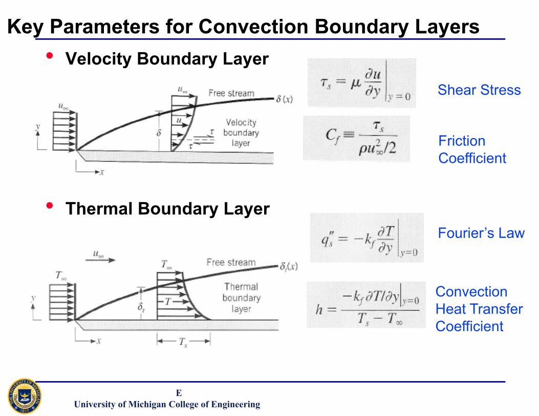
Key Parameters for Convection Boundary Layers• Velocity Boundary Layer
• Thermal Boundary Layer
Shear Stress
Friction Coefficient
Fourier’s Law
Convection Heat TransferCoefficient

Katsuo Kurabayashi / MEUniversity of Michigan College of Engineering
Laminar Flow Over a Flat Plate
Heat Transfer from a Plate with a Constant Heat Flux
The Nusselt number is the non-dimensional temperature gradient at the surface, providing a measure of the convection heat transfer occurring at the surface.
NuL hLk f
0.664ReL1/2 Pr1/3
Heat Transfer from an Isothermal plate
NuL hLk f
0.680ReL1/2 Pr1/3
ReL VL
; Pr
Fundamentals of Heat and Mass Transfer, Incropera and Dewitt, Seventh Edition

Katsuo Kurabayashi / MEUniversity of Michigan College of Engineering
Laminar Flow Over a Cylinder
NuD hDkf
CReDm Pr1/3
ReL VD
; Pr
Heat Correction factors for other shapes
NuD hDkf
CReDm Pr1/3
Fundamentals of Heat and Mass Transfer, Incropera and Dewitt, Sixth Edition

Katsuo Kurabayashi / MEUniversity of Michigan College of Engineering
Heat Transfer Coefficient for a collection of FinsLet’s consider a flow across banks of tubes to model the flow across the heat sink fins.

Katsuo Kurabayashi / MEUniversity of Michigan College of Engineering
How can we predict the value of h?
Aligned arrangement Staggered arrangement
Maximum Reynolds Number for flow across fins

Katsuo Kurabayashi / MEUniversity of Michigan College of Engineering
How can we predict the value of h?
Aligned arrangement Staggered arrangement
Maximum Reynolds Number for flow across fins

Katsuo Kurabayashi / MEUniversity of Michigan College of Engineering
How can we predict the value of h?We can obtain Nusselt number from empirical relations.
NL = total number of finsPrs = Prandtl Number at the average fin temperature Ts.
Fundamentals of Heat and Mass Transfer, Incropera and Dewitt, Seventh Edition
All properties except Prs to be evaluated at the mean temperature Tm = (Ti + TO)/2
Ti : air temperature at the inlet of the tube bank
To : air temperature at the exit of the tube bank

Katsuo Kurabayashi / MEUniversity of Michigan College of Engineering
How can we predict the value of h?We can obtain Nusselt number from empirical relations.
If NL < 20
Fundamentals of Heat and Mass Transfer, Incropera and Dewitt, Seventh Edition
C2 value

Katsuo Kurabayashi / MEUniversity of Michigan College of Engineering
How can we predict the value of h?We can obtain Nusselt number from empirical relations.

Katsuo Kurabayashi / MEUniversity of Michigan College of Engineering
How can we predict the value of h?We can obtain Nusselt number from empirical relations.

Katsuo Kurabayashi / MEUniversity of Michigan College of Engineering
Safety
1) The chip can get pretty hot
2) Do not supply more than 12 V to the fan


![Calculation Method for Forced-Air Convection Cooling Heat ... · tion cooling [1], forced-air convection cool ing, heat pipe cooling [2], and liquid cooling. F orced -air convection](https://img.pdfslide.us/doc/110x75/5e6929cd70728524d16ffef2/calculation-method-for-forced-air-convection-cooling-heat-tion-cooling-1.jpg)