Embed Size (px)
Citation preview

A Project report on
UN-MANNED ARMY WAR TANKER WITH AUTOMATIC SELF
DEFENDING AND ATTACKING SYSTEM
BACHELOR OF TECHNOLOGY
in
MECHANICAL ENGINEERING
Submitted By
SUSHANG SHAH - 105D1A03A4
Under the Guidance of
Mr. D. MADHAVA REDDY
Associate professor
Department of Mechanical Engineering,
KASIREDDY NARAYANREDDY COLLEGE OF ENGINEERING &
RESEARCH
Affiliated to Jawaharlal Nehru Technological University.
2010 – 2014

ACKNOWLEDGEMENT A project work on this magnitude is not possible without the help of several
people. It is with immense satisfaction that I present our practical experience in the form
of a project carried out in ARUNODAYA ELECTRO POWER TECHNOLOGIES
PVT. LTD
It is with a feeling of great pleasure that I would like to express my most sincere
heartfelt gratitude to Mr. D. MADHAVA REDDY(Associate professor) KNRR,
Hyderabad for suggesting the topic for my thesis report and for his ready and able
guidance throughout the course of my preparing the report. I am greatly indebted to him
for his constructive suggestions and criticism from time to time during the course of
progress of my work.
I express my sincere thanks to Mr. S. AMARESH BABU, principal & Mr. D.
MADHAVA REDDY, Head of Department of Mechanical Engineering, KNRR,
Hyderabad.
I am thankful to teaching and non teaching faculty members of the mechanical
engineering department who helped directly or indirectly in successful completion of the
project.
I am very grateful to my family and friends for their constant support and
encouragement during the project period.
SUSHANG SHAH - 105D1A03A4

CONTENTS
Abstract IV
List of figures VI
List of tables VII
1. INTRODUCTION 01 - 12
1.1 Potential of unmanned warfare 02
1.2 Need for unmanned 02
1.3 Unmanned ground vehicles (UGV) 03
1.3.1 Tele-operated UGV
1.3.2 Autonomous UGV
1.4 Land theatre unmanned warfare 05
1.5 Unmanned warfare in the air 07
1.5.1 Non Lethal UAV
1.5.2 Lethal UAV
1.6 Naval unmanned warfare 10
1.7 Technology for the development
of unmanned systems 11
2. WAR TANKER 13 - 16
2.1 Light Tanks 14
2.3 Heavy Tanks 14
2.3 History 15
3. FUNCTIONAL DESCRIPTION 17 – 38
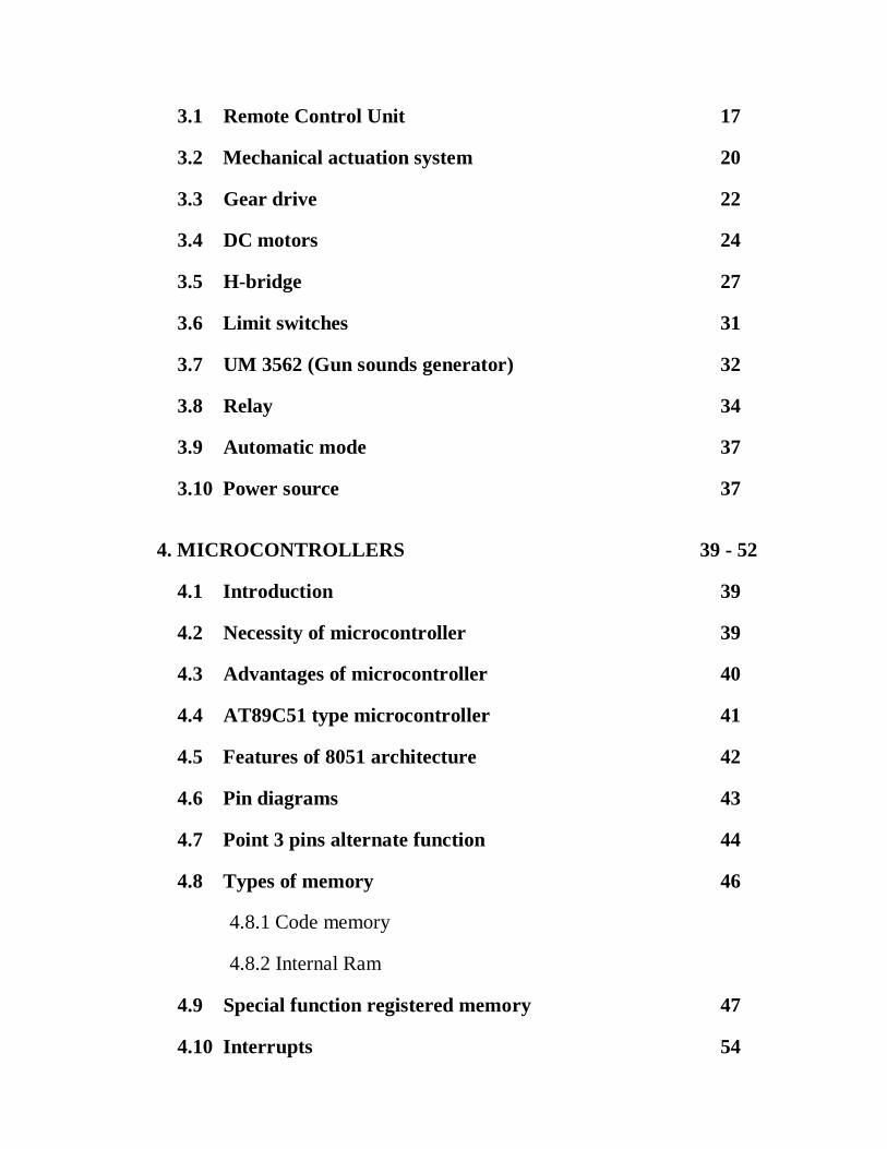
3.1 Remote Control Unit 17
3.2 Mechanical actuation system 20
3.3 Gear drive 22
3.4 DC motors 24
3.5 H-bridge 27
3.6 Limit switches 31
3.7 UM 3562 (Gun sounds generator) 32
3.8 Relay 34
3.9 Automatic mode 37
3.10 Power source 37
4. MICROCONTROLLERS 39 - 52
4.1 Introduction 39
4.2 Necessity of microcontroller 39
4.3 Advantages of microcontroller 40
4.4 AT89C51 type microcontroller 41
4.5 Features of 8051 architecture 42
4.6 Pin diagrams 43
4.7 Point 3 pins alternate function 44
4.8 Types of memory 46
4.8.1 Code memory
4.8.2 Internal Ram
4.9 Special function registered memory 47
4.10 Interrupts 54

5. SOFTWARE DETAILS 55 - 56
5.1 Keil’s Software 55
5.2 Simulation 55
5.3 Use of software for execution of microcontroller program 55
5.4 Problems faced by embedded program developers 56
6. SCOPE OF DEVELOPEMENT 57 – 59
6.1 Limitations 58
6.2 Future scope 58
Conclusion 60
References 61
CHAPTER – 1
INTRODUCTION
Manpower scarcity has been a perennial problem for many armed forces around
the world. Over the years, there has been a decline in the absolute numerical make-up of
these organizations, which, if not managed properly, can affect their operational
capabilities. This scarcity is a situation that is unlikely to improve in the foreseeable
future, given the current low birth rates and conflicting demands for manpower.
From a numerical perspective, this constraint means that the armed forces cannot
mass together the sheer number of ground troops as before. From a risk perspective,
every soldier on the battlefield is now a precious resource which should not be exposed to
unnecessary risks. This translates into further constraints for battle planners, who may not
have the leeway to select the riskier but more expedient military options. Finally, from
the skills perspective, smaller population bases make it difficult to find, select, train and
develop specialized combatant resources like pilots and submariners.
Thus, it is crucial that new avenues be explored to circumvent this prevalent trend
of manpower shortages. One viable solution lies in exploiting technology and pushing the
limits of force multipliers. Within the domain of force multipliers, there lies a relatively
new discipline, unmanned warfare.
The definition of 'unmanned' chosen for this article is fairly loose, as the emphasis
is not solely on taking men out of machines but also on how to employ technology to
make better use of its manpower. Thus, while the focus is on unmanned warfare in its
literal sense, the article will also touch on some equipment or systems which result in
lower manpower usage (or higher operational capability with the same manning). In
doing so, please accept that some aspects of this article border on technological
innovation as opposed to unmanned warfare per se.

1.1 Potential of unmanned warfare :
Unmanned warfare is a relatively new approach in the conduct of warfare, where
the boundaries are not well charted and limited largely by our imaginations. Unmanned
warfare will not only help overcome manpower and resource constraints but will also
enhance operational capabilities, since it can now move into areas where mankind has
previously feared to tread. With unmanned warfare, the competitive advantage can be
swung such that human numerical superiority is no longer an overwhelming advantage or
a pre-requisite for victory.
1.2 Need for unmanned :
The impetus to go unmanned include optimizing the deployment of manpower,
enhancing operational capabilities and being able to venture into territory once out-of-
bounds to mankind (e.g. deep ocean, space, etc). In particular, unmanned systems should
be used to replace humans where the work is dangerous, dirty or dull.
Some specific advantages in going unmanned include:
Reduction in manpower requirement: Developments in unmanned technology
now enables machines to perform tasks once undertaken by operators with equal
if not better precision. This direct substitution of manpower will lead to a
corresponding reduction in manpower needs.
Overcome fatigue and human error: Machines do not tire out as easily as men.
Operations that require constant alert or repetitive work over long durations are
thus potential areas where unmanned warfare can be profitably employed.
Minimize hazards: Risks to humans can be reduced as unmanned systems can
take over hazardous jobs previously done by human beings.
Cost savings: Besides manpower savings, there are also cost reductions in the
form of human cost (life) savings, training cost savings or even system cost
savings as new unmanned systems can enhance work flow and improve general
work cycles.
Maximum ammo loading : Since this tanker have no human interference the
space which is leftover can be used to load more ammo, which provides more
durability in the warfare.

Decision making: Although unmanned systems are becoming increasingly
sophisticated and 'intelligent', it is still difficult to entrust machines with
subjective decision making. We must avoid careless delegation of responsibilities
to technology that perform only under programmed patterns.
Unmanned Ground Vehicles (UGV) save lives and improve national defense capabilities
by providing agencies of the Department of Defense (DOD) with the control system architectures,
advanced sensor systems, research services, and standards to achieve autonomous mobility for
unmanned ground vehicles.
1.3 Unmanned Ground Vehicles (UGV)
UGV are robotic platforms that are used as an extension of human capability. This
type of robot is generally capable of operating outdoors and over a wide variety of
terrain, functioning in place of humans.
UGVs have counterparts in aerial warfare (unmanned aerial vehicle) and naval
warfare (remotely operated underwater vehicles). Unmanned robotics is actively being
developed for both civilian and military use to perform dull, dirty, and dangerous
activities. Some UGVs are employed in War in Iraq.
Fig 1.1 UGVs Prototype
There are two general classes of unmanned ground vehicles:
1. Tele-operated ones and
2. Autonomous ones.
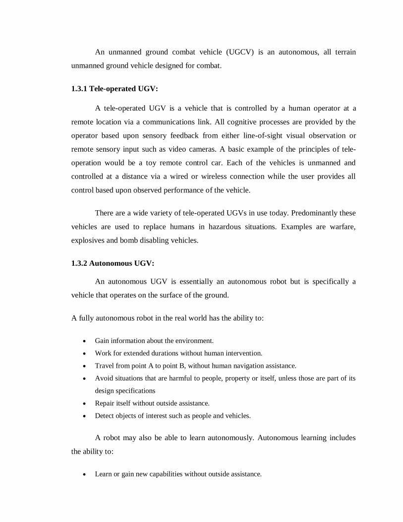
An unmanned ground combat vehicle (UGCV) is an autonomous, all terrain
unmanned ground vehicle designed for combat.
1.3.1 Tele-operated UGV:
A tele-operated UGV is a vehicle that is controlled by a human operator at a
remote location via a communications link. All cognitive processes are provided by the
operator based upon sensory feedback from either line-of-sight visual observation or
remote sensory input such as video cameras. A basic example of the principles of tele-
operation would be a toy remote control car. Each of the vehicles is unmanned and
controlled at a distance via a wired or wireless connection while the user provides all
control based upon observed performance of the vehicle.
There are a wide variety of tele-operated UGVs in use today. Predominantly these
vehicles are used to replace humans in hazardous situations. Examples are warfare,
explosives and bomb disabling vehicles.
1.3.2 Autonomous UGV:
An autonomous UGV is essentially an autonomous robot but is specifically a
vehicle that operates on the surface of the ground.
A fully autonomous robot in the real world has the ability to:
Gain information about the environment.
Work for extended durations without human intervention.
Travel from point A to point B, without human navigation assistance.
Avoid situations that are harmful to people, property or itself, unless those are part of its
design specifications
Repair itself without outside assistance.
Detect objects of interest such as people and vehicles.
A robot may also be able to learn autonomously. Autonomous learning includes
the ability to:
Learn or gain new capabilities without outside assistance.

Adjust strategies based on the surroundings.
Adapt to surroundings without outside assistance.
Autonomous robots still require regular maintenance, as with all machines.
1.4 Land unmanned warfare :
The land theatre has traditionally been the largest employers of manpower. With
reducing manpower and increasing battlefield risks, technology is no longer regarded as
just a force multiplier, but rather one that would produce a paradigm shift in war fighting.
Manpower requirements can be dramatically reduced in the battlefield with
unmanned platforms. UGVs, coupled with appropriate sensors, are able to give
commanders a bird's eye view of the battlefield, without having to incur risks to himself,
observers or pilots. Such a view has obvious benefits - to the intelligence community, to
manoeuvre commanders and to targeting agencies. UGVs can also be employed as rebro
or electronic warfare platforms. In the longer term, armed UGVs may well become
operationally and economically viable, thus enabling them to perform tactical attack
roles.
Tactical Unmanned Ground Vehicles (TUGV), the ground equivalent of UGVs,
are able to perform some of the roles currently done by UAVs. Equipped with weaponry
or sensors, they could complement or even replace some of the roles assumed by scouts
and signalers. In these roles, one edge of the TUGV over the UAV is its staying power
and ability to hold ground. TUGV is also able to breach and open minefields/ obstacles
and clear axes for armor and logistics re-supply.
Unmanned Ground Sensors (UGS) are a cost effective replacement for manned
systems that have previously been used for monitoring or for communications. They can,
for example, be deployed by helicopters or C-130 to critical points to detect time critical
mobile targets (i.e. maneuver forces, tank columns). They can also be used as signals
nodes to serve as communication relay platforms, thus relieving signals personnel from
performing a tedious and time consuming job.
Dramatic breakthrough in robotics and tele-operated mine breaching can greatly
reduce the labor-intensive nature of mine-clearing. Also, development of new mine
detection technology now permits untrained troopers, using devices which incorporate
thermal imaging and ground penetrating radar, to be able to detect metallic and non-
metallic mines. This reduces the dependence on specialized combat engineers and
simultaneously increases operational capability through speedy mine detection.
There are a few additional unmanned systems that are a long way from seeing
operational employment, but which are worth mentioning in view of their long term
potential. For example, developments in unmanned technology include robots that can
undertake dangerous and dirty work. The US military has been pursuing the concept of
'Pointman' for some time. Pointman is a light-weight, sensor-laden, armed robot used to
reconnoiter buildings, bunkers and tunnels, in order to detect booby traps, explosives and
the enemy. It will be able to climb stairs, operate in all weather and light conditions, and
is expected to be especially useful in what the US Army terms 'operations other than war'.
Still looking at longer term developments, armor units may one day field
remotely-controlled tanks. One of the modes of employment is to have one manned tank
control and operate two unmanned, remote-controlled tanks. Navigation and targeting
inputs provided by the tank commander are utilized by the remote-controlled tanks to
acquire and destroy targets. The firepower of armor units can hence be enhanced
tremendously with fewer or similar numbers of tank crews.
Remotely-controlled self-propelled guns or howitzers could operate together with
manned guns using the same concept as the remote controlled tanks. This concept seems
closer to fruition than unmanned tanks, as the technological challenges appear less
daunting. The need for human judgment in each individual fighting unit also appears less
critical.
1.5 Unmanned warfare in air:
Plagued with constraints of limited human resources and a sizable reduction in the
pool of youths who fulfill stringent recruitment requirements, air forces around the world
will be compelled to explore means to maintain or extend their operational capabilities
with an increasingly trim fighting force.
The employment of unmanned platforms in the modern battlefield serves to
alleviate problems caused by the shortage in manpower and resources. In employing
unmanned platforms, pilots may also be removed from aircraft penetrating defended
enemy airspace, thus reducing the danger arising from exposure to hostile fire.
The benefits are immediately obvious. First, human attrition will be reduced.
Second, the aircrew whose functions are now assumed by unmanned platforms can be
channeled to other crucial functions like air defense, C31 and transportation missions.
Finally, planners will be able to undertake more risky but decisive combat missions, such
as SEAD, without exposing aircrew to excessive risk.
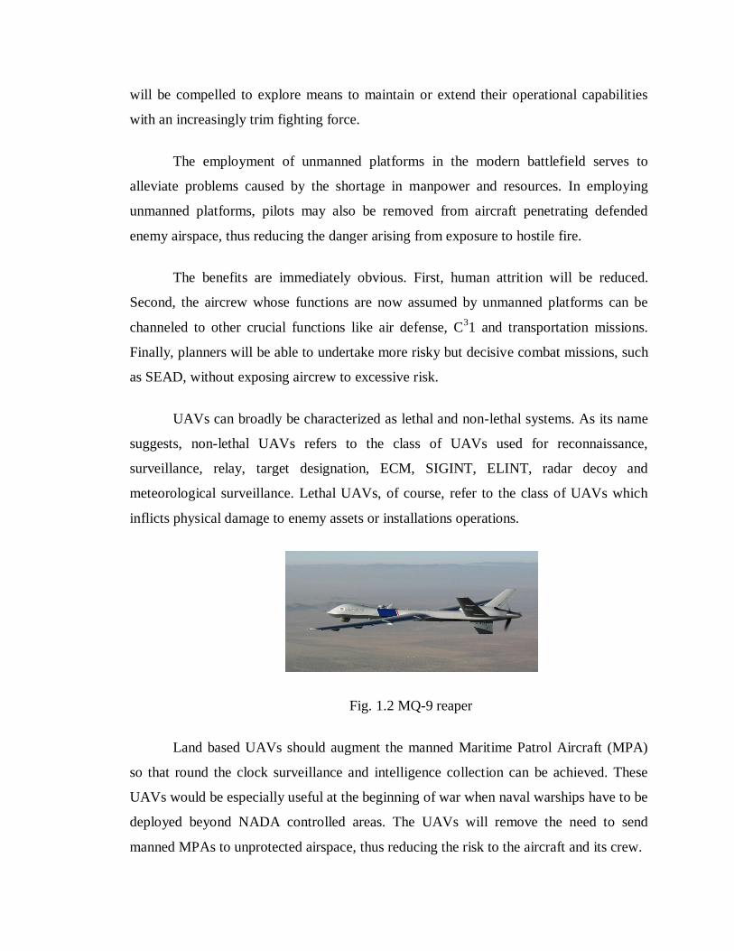
UAVs can broadly be characterized as lethal and non-lethal systems. As its name
suggests, non-lethal UAVs refers to the class of UAVs used for reconnaissance,
surveillance, relay, target designation, ECM, SIGINT, ELINT, radar decoy and
meteorological surveillance. Lethal UAVs, of course, refer to the class of UAVs which
inflicts physical damage to enemy assets or installations operations.
Fig. 1.2 MQ-9 reaper
Land based UAVs should augment the manned Maritime Patrol Aircraft (MPA)
so that round the clock surveillance and intelligence collection can be achieved. These
UAVs would be especially useful at the beginning of war when naval warships have to be
deployed beyond NADA controlled areas. The UAVs will remove the need to send
manned MPAs to unprotected airspace, thus reducing the risk to the aircraft and its crew.

1.5.1 Non-Lethal UAVs
Many non-lethal UAV roles have become well-established in many armed forces.
Reconnaissance UAVs are widely used to map the enemy's defense locations, practices,
electronic profiles and vulnerabilities. As their endurance and payload improve, these
UAVs can take on the more demanding surveillance and airborne early warning functions
as well. EW UAVs are capable of using chaff and ECM to degrade the enemy's radar or
communications.
Used together with anti-radiation missiles or drones, these EW UAVs can
effectively shut down the enemy's radar operations. In SEAD) operations, UAVs can be
deployed as decoys to entice the defenders to turn on their radars or fire their missiles at
the wrong targets. Manned strikers following behind the UAVs can then move in to
complete their missions with relative ease.
1.5.2 Lethal UAVs
Lethal UAVs can best be looked at by dividing them into two distinct categories:
counter-air and strike. I will examine these two components separately and assess the
viability of UAVs to replace manned aircraft during wartime.
Air-to-air combat is very dynamic and dependent upon the pilot's judgment and
skill to outwit and out-manoeuver the aggressor so as to get into an advantageous position
for the kill. This applies even when an aircraft is armed with the most advanced AAMs,
especially if the enemy is similarly equipped. Furthermore, in an air battle, the air picture
is usually a complex one, with many real-time injects like weather, use of ECM or
ECCM, changes in tactics, attention, etc. The pilots, with the help of GCI, will have to
make impromptu, split- second decisions to circumvent the friction of war.
The use of UAV’s as interceptors will expose one of its biggest shortcomings; its
lack of decision making abilities. However advanced the UAV, it is still unable to replace
the pilot in a dog-fight. The situational awareness is just not the same. More often than
not, UAVs are very scenario dependent and operate well only in a predictable
environment. The lack of a human on board limits a UAV to perform mostly pre-
programmed standard functions.

Although UAVs cannot replace manned fighters in air-to-air combat, they can be
used as decoys to reduce friendly losses. Decoys can be scrambled together with manned
interceptors to complicate the enemy's air picture, distracting their pilots or causing them
to expend their missiles on the decoys.
Strike missions are a hazardous task as the strike aircraft are susceptible to many
threats: enemy fighters, SAMs, AAA etc. A typical strike mission would involve a lot of
resources. Besides the strikers, sweepers are to fly ahead and clear the path for their
transit. In addition, to have accompanying escort fighters are needed to eliminate hostile
aircraft that slip through to threaten the strike aircraft.
UAVs can be used to reduce the heavy demands and risks of strike missions.
Many strike aircraft and bombers follow a pre-determined route into enemy territory and
strike specific targets on the ground. The predictable nature of this task makes it suitable
for UAV execution. Technically, the cruise missile is a small, disposable UAV. These
missiles are cost-effective, proven in war, and do not need escorts or sweepers. Re-usable
bomber UAVs are also under development, but these are probably less flexible and
effective than missiles as they would require a great deal more support for them to fulfill
their role.
A final benefit of using UAVs is that they are less dependent on runways. Most
unmanned platforms are easier to store and deploy than fixed wing aircraft, and many do
not need a long runway to launch from. Of particular significance, land or sea launched
cruise missiles would allow an armed force to retain a long-range strike capability even if
its runways were closed and its aircraft temporarily grounded.
1.6 Naval unmanned warfare :
Unmanned platforms are relatively new naval forces. Naval forces should
consider adopting more unmanned systems in the naval theatre, with manned warships
deployed as a controlling force or a follow-up strike force when a high casualty rate has
been inflicted on the opposing force.

They are the Unmanned Aerial Vehicle (UAV), Unmanned Undersea Vehicle
(UUV) and Sound Ocean Surveillance System (SOSUS). The following discusses the
ways these platforms can replace or supplement a navy's manned platforms and improve
its operational effectiveness.
Navies should acquire a mix of ground based and sea launched UAVs. Complete
surveillance packages configured for tactical surveillance should be available in the sea
launched version. Real time data-linked, probably through satellite communications,
should be the main command and control requirement so that commanders ashore and at
sea are able assess the reconnaissance picture. High adaptability to mission changes and
reassignment should also be essential features of the vehicle.
Sea-launched UAVs would by necessity, be lighter and have less endurance than
their land based counterparts. However, they have an important role in that they provide
flexibility and autonomy to the commanders at sea, who can then solve immediate
tactical surveillance problems without assistance from shore.
For littoral warfare, UAVs should be able to solve some of the problems when
ships operate in proximity to land. When warships operate in hostile coastal waters, the
risk is invariantly higher as they are subjected to threat from ashore and ambushing
enemy military or para-military craft. Surveillance pictures provided by UAVs would
finish task group commanders with valuable early warning of enemy presence.
Clearance of island groups by warships is another challenging task. In this case, a
naval force should further exploit unmanned technology by acquiring remote controlled
arsenal craft equipped with short to medium range high discrimination missiles to engage
hostile craft detected by the UAV.
In the area of naval gun fire support, UAVs can provide spotting and eventually
Target Damage Assessment to the Shore Bombardment Commander.
1.6.1 Undersea Vehicles :
The application of unmanned vehicles for underwater warfare is predominantly in
the area of mine clearance. Mine clearance in hostile waters can be fulfilled with the Self-
propelled Acoustic and Magnetic Minesweeping System (SAMMS). This unmanned,
remotely controlled mine sweeping craft is capable of establishing a safe route through
mined waters.
Navies could consider acquiring a passive mine clearance capability so as to
expand their mine-sweeping versatility. The US Navy is currently developing a tactical
scale Unmanned Undersea Vehicle (UUV) to conduct covert, fully autonomous, long
duration mine warfare and tactical oceanography in littoral waters. To date, the UUV has
demonstrated a navigational accuracy of 0.18% of distance traveled. Such a vehicle
allows naval forces to conduct covert mine clearance and seabed surveys during POT
when aggressive counter-mine measures could not be conducted. Another advantage of
the UUV is that it can be launched covertly from a submarine.
1.6.2 Anti-Submarine Warfare :
Manned assets are still largely used in the area of Anti-Submarine Warfare, as it
remains the playground for tacticians. However, SOSUS can be used to monitor
submarine movements at various key points in our area of operations. This will reduce
the demands on manned anti-submarine warfare assets. With further development in
UAVs, ASW packages can also be fitted onboard to provide an extended arm to airborne
ASW.
1.7 Technology for the development of unmanned systems :
Competition to dominate the battlefield of the future is competition to create,
adopt and dominate emerging technologies. In the area of unmanned warfare, getting
ahead requires:
a. A keen understanding of how future battles would be fought and how unmanned
warfare fits in.
b. A developmental process for exploring, assimilating and exploiting current and
emerging future technologies applicable in unmanned systems.

The unmanned warfare paradigm may be defined in three dimensions. Service
groups broadly describe the various services in the Armed Forces, or who is being
satisfied. Service functionalities describe service needs, or what is being satisfied.
Technologies describe the way, or how the service group’s needs are satisfied. The who
and what, having already been discussed, we can see that the how may be classified into
three main areas of required technologies. These are:
a. Sensory: This is predominantly in the departments of sight & sound (e.g. to detect the
enemy), touch (e.g. to ascertain reality) and smell (e.g. to determine toxicity of air).
b. Mechatronics: This entails the delivery systems upon which the unmanned systems
would ride on. It would include technologies such as propulsion, aerodynamics and
robotics.
Through a systematic and rigorous program of developing this unmanned
capability, new core competencies would emerge and these are potential highways to the
future for our local defense industry. Besides providing a country's armed forces with a
military advantage, technologies applied in unmanned systems have potential for a
myriad of commercial payoffs. For instance, car manufacturers are beginning to explore
unmanned driving on highways for safety as well as time and highway efficiency. Hence,
unmanned technology offers our defense industry an attractive area to venture into, with
additional potential for commercial payoffs.

CHAPTER – 2
WAR TANKERS
WAR TANKER :
A tank is a tracked, armored fighting vehicle designed for front-line combat
which combines operational mobility and tactical offensive and defensive capabilities.
Firepower is normally provided by a large-caliber main gun in a rotating turret and
secondary machine guns, while heavy armor and all-terrain mobility provide protection
for the tank and its crew, allowing it to perform all primary tasks required of armored
troops on the battlefield.
Fig 2.1 Parts of a war tanker
The tank remains the “King of the battle field” having come into its own during
world war 1. Designed initially to navigate the miles of trenches and obstacles along the
western front, the tank ( then known as the “Landship”) was first envisioned in an
infantry support role. The first tank-versus-tank battle took place in the war between

british and german tanks with results being rather anticlimatic. As
experience bagan to dedicate function, the tank was later user to spearhead
critical alied offensives in breaking down enemy positions and causing general havoc. In
the end, the armored vehicle became a permanent fixture of the battlefield – evolvinginto
the spearhed of any successful land campagin to date.
World War 1 saw the origins of the "Landship", which became the "tank" as
we know it - all thanks to British engineering out of Bovington, England.
World War 1 proved a testing ground concerning aspects related to modern
warfare. Poison gas, the flamethrower, the aircraft (as a fighter, light bomber and heavy
bomber), the machine gun and the "tank" were all born in their practical sense in during
the dark days of The Great War. Early "tanks", known then as "landships" after their sea-
going battleship counterparts, were largely pioneered by the British Navy and began life
as awkward rhomboidal-shaped steel beasts with side-mounted cannon and machine gun
armament. Such armored vehicles helped to break the stalemate along the Western Front
for the Allies and force the Armistice of November 1918. By the end of the war, the
revolutionary French Renault FT-17 Light Tank was in use and it brought about the
revolving turret that proved a common feature in all future tank developments since.
Today's massive and powerful war machines can all trace their roots back to these early
ground-breaking initiatives.
2.1 Light tanks :
Light tanks continued to be built, but for very limited roles such as amphibious
reconnaissance, support of Airborne units, and in rapid intervention forces which were
not expected to face enemy tanks. The Soviet PT-76 is a good example of a specialized
light tank. It is amphibious and has the firepower to kill other reconnaissance vehicles,
but it is very lightly armored. The US M551 Sheridan had similar strengths

and weaknesses, but could also be airdropped, either by parachute or
LAPES.
2.2 Heavy tanks :
Heavy tanks continued to be developed and fielded along with medium tanks until
the 1960s and 1970s, when the development of anti-tank guided missiles and powerful
tank guns rendered them ineffective in their role. The combination of large HEAT
warheads, with a long effective range relative to a tank gun, and with high accuracy
meant that heavy tanks could no longer function in the stand-off, or overwatch role.
Much cheaper antitank guided missiles could fill this role just as well. Medium tanks
were just as vulnerable to the new missiles, but could be fielded in greater
numbers and had higher battlefield mobility. Furthermore, the value of light tanks for
scouting was diminished greatly by helicopters, although many light tanks continued to
be fielded.
2.3 History :
The tank is the 20th century realization of an ancient concept: that of
providing troops with mobile protection and firepower. The internal
combustion engine, armor plate, and the continuous track were key
innovations leading to the invention of the modern tank.
Armored trains appeared in the mid-19th century, and various
armored steam- and petrol engines vehicles were also proposed. The first
armored car was produced in Austria in 1904. However, all were restricted
to rails or reasonably passable terrain. It was the development of a practical
caterpillar track that provided the necessary independent, all-terrain
mobility.
Many sources imply that Leonardo da Vinci and H.G. Wells in some way foresaw
or "invented" the tank. Da Vinci's late 15th century drawings of what some describe as a
"tank" show a man-powered, wheeled vehicle with cannons all around it. However the
human crew would not have enough power to move it over larger distance, and usage of
animals was problematic in a space so confined.
The machines described in Wells's 1903 short story The Land Ironclads are a step
closer, in being armor-plated, having an internal power plant, and being able to cross
trenches. Some aspects of the story foresee the tactical use and impact of the tanks that
later came into being. However, Wells's vehicles were driven by steam and moved on
Pedrail wheels, technologies that were already outdated at the time of writing. After
seeing British tanks in 1916, Wells denied having "invented" them, writing, "Yet let me
state at once that I was not their prime originator. I took up an idea, manipulated it
slightly, and handed it on." It is, though, possible that one of the British tank pioneers,
Ernest Swinton, was subconsciously or otherwise influenced by Wells's tale.
The "caterpillar" track arose from attempts to improve the mobility of wheeled
vehicles by spreading their weight, reducing ground pressure, and increasing their
adhesive friction. Experiments can be traced back as far as the 17th century, and by the
late nineteenth they existed in various recognizable and practical forms in several
countries.
It is frequently claimed that Richard Lovell Edgeworth created a caterpillar track.
It is true that in 1770 he patented a "machine, that should carry and lay down its own
road", but this was Edgeworth's choice of words. His own account in his autobiography is
of a horse-drawn wooden carriage on eight retractable legs, capable of lifting itself over
high walls. The description bears no similarity to a caterpillar track.
The first
combinations of the three principal components of the Tank appeared in the decade
before World War One. In 1903, a Captain Levavasseur of the French Artillery proposed
mounting a field gun in an armored box on tracks. Major W.E. Donohue, of the British
Army's Mechanical Transport Committee, suggested fixing a gun and armored shield on
a British type of track-driven vehicle. In 1911, a Lieutenant Engineer in the Austrian
Army, Günther Burstyn, presented to the Austrian and Prussian War Ministries plans for

a light, three-man tank with a gun in a revolving turret. In the same year an Australian
civil engineer named Lancelot de Mole submitted a basic design for a tracked, armored
vehicle to the British War Office. In Russia, Vasiliy Mendeleev designed a tracked
vehicle containing a large naval gun.
All of these ideas were rejected and, by 1914, forgotten, although it was officially
acknowledged after the War that de Mole's design was at least the equal of the tanks that
were later produced by Great Britain, and he was voted a cash payment for his
contribution. Various individuals continued to contemplate the use of tracked vehicles for
military applications, but by the outbreak of the War no one in a position of responsibility
in any army had any thoughts about tanks.
CHAPTER – 3
FUNCTIONAL DESCRIPTION
The functional description and working operation as per the block diagram is
explained below. The block diagram and the circuit diagram are provided in the next
chapter.
As mentioned in the introduction the unmanned vehicles are either operated
autonomously or through tele-communications i.e., remote. The robot (war tanker)
designed here is the remote operated one. Through this remote the robot can be controlled
sitting at a safe place. The remote is designed with eleven control keys, micro-controller
(89C2051) and the zigbee transmitter (Tarang). Out of these eleven keys, four keys are
used to control the vehicle’s direction i.e., to operate the in forward, backward, right and
left directions. Two keys are to rotate the gun on the tank in clockwise and anti-clockwise
directions. Two keys are used to set the tanker in automatic or manual mode of operation.
Two keys are used for the gun to lift up and down in vertical direction and one key is
used to start firing from the gun.
When automatic mode of operation is selected, the vehicle movement will only be
controlled where as gun firing will be done automatically depending on the target hit
direction. But in manual operation, everything is to be controlled through the remote
itself.
3.1 Remote control unit :
The remote control unit is nothing but the transmitter unit through which the
tanker is controlled. The main components present in this unit are the push buttons, micro
controller (89C2051), Zigbee transmitter and a battery to provide power supply to all
these components. As mentioned earlier, a total of eleven keys (push buttons) are used to
control the vehicle and these are interfaced with the 89C2051 micro controller.
Depending on the key pressed, the controller generates a unique 8 bit binary code which
is fed to the Zigbee transmitter for modulation. The detailed explanation about the Zigbee
Tarang module is provided below.

The data-transmitting unit (hand held Equipment) including 89C2051
microcontroller designed to operate at 5V DC, and the battery used in the card is 9V
pack, therefore with the help of a voltage regulator of 7805, constant supply of +5V is
derived. Supply to the circuit is provided through the ON/OFF key and a small keyboard
designed with 11 keys is interfaced with this microcontroller. This keyboard is designed
to generate the data that is stored in RAM and it is delivered through output pin of the
controller (transmitter). The output of the microcontroller is modulated within the ISM
2.4 - 2.4835 GHz frequency band with IEEE 802.15.4 baseband and transmits the binary
data to space. Any digital data generated by the keyboard is transmitted as it is, once the
key is pressed in the transmitter, binary data is transmitted and according to that data, the
receiving controller unit has to be programmed.
The main function of the data transmitting section is to generate 8-bit binary code
that is to be transmitted through Zigbee transmitter. The 8-bit binary code produced by
the keyboard is fed to microcontroller, which functions as encoder; the data obtained
from the keyboard is stored and it is converted into 8-bit information which is transmitted
through amplified modulated input signal. If any key is pressed; that information is
converted into 8-bit data. For example, if No.1 key is pressed, 00000001 code is
generated. Likewise each key function differs from another key to generate a different 8-
bit code. Based on this code, the other micro controller used in the receiving module,
which is designed as 8-bit code decoder, decodes this data and compares with the pre-
defined program prepared in assembly language and operates the vehicle (robot).
The output of the (Encoder) microcontroller is fed to Zigbee
transmitter, for radiating the pulsating energy into air. The function of a
radio frequency (RF) transmitter is to modulate, up convert, and amplify
signals for transmission into free space. An RF transmitter generally
includes a modulator that modulates an input signal and radio frequency
power amplifier that coupled to the modulator to amplify the modulated

input signal. The radio frequency power amplifier is coupled to an antenna
that transmits the amplified modulated input signal.
The Zigbee transmitter used in our project is Tarang – F4. This RF transmitter
transmits data in the frequency range of 2.4 - 2.4835 GHz with a range of approximately
50-feet (open area) outdoors. Indoors, the range is approximately 20 feet, and will go
through most walls. Tarang – F4 has features which includes small in size, low power
consumption and operates at 3.3 volts DC, excellent for applications requiring short-
range RF signal.
Fig 3.1 Zigbee tarang
The data receiving module consist Zigbee receiver, DC motors with their driving
circuits, gun fining sound simulator IC and limit switches that are interfaced with the
89C51 microcontroller as source of information at the receiving side. To control the
moving mechanism based on the input information, H-bridge IC’s are connected at the
output of microcontroller and these are used to control the DC motors ultimately, which
controls the robot as well as the gun firing and its direction. Over all function of the block
diagram is to install an electro-mechanical vehicle operated in all possible directions. The
description is as followed.
The RF signal transmitted by the transmitter is detected and received by this
section of the receiver. This binary encoder data is sent to the decoder for decoding the
original data. The receiver receives an RF signal, converts the RF signal to an IF signal,
and then converts the IF signal to a base band signal, which is then provides to the base
band processor. As is also known, RF transceivers typically include sensitive components
susceptible to noise and interference with one another and with external sources. The
Zigbee (RF) receiver is coupled to the antenna and includes a low noise amplifier, one or
more intermediate frequency stages, a filtering stage, and a data recovery stage. The low
noise amplifier receives an inbound RF signal via the antenna and amplifies it.
The Zigbee receiver receives the RF signal, which is in the frequency
of 2.4 GHz. The receiver operates at 3.3 volts-DC, and has both linear and
digital outputs and its tunable to match the frequency of the transmitter unit.
The program is fixed, it cannot be changed, depending up on the program
prepared for controller, and the information produced by the keyboard at transmitting
end, the received information if it is tallied with the pre-defined program, then the
microcontroller at receiving end energizes the DC motors driving circuit to control or
operate the tanker (robot) automatically.
Depending on the keys pressed from the remote, the data is modulated and
transmitted by the transmitter, which will be demodulated by the receiver present on the
vehicle (ROBOT) and is fed to the 89C51 micro controller. The controller decodes the
data and takes the necessary action depending on the program written in it. The vehicle
(robot) movement can be controlled with the DC motors that will be interfaced to the
controller through the H-bridge IC L293D. By using this IC we will be able to drive two
DC motors. So two H – Bridge IC’s are used to drive the four DC motors. The detailed
explanation of the H-bridge IC operation, and automatic target hit detection system are
explained in the further sections.

3.2 Mechanical actuation section :
The mechanical system is considered as motion converter, this can be created by
implementing electro-mechanical techniques. The concept is to transform the motion
from one form to some other required form by using suitable mechanical and electrical
devices. In this project work the technique of transform the rotational motion into circular
and linear motion is implemented. For this purpose DC motors are used to create the
motion in the gun mechanism of the tanker as well as its movement. These motors are
constructed with reduction gear mechanism which is built in with the motor internally. As
the machine is designed as prototype module, low rating motors are used to drive the
mechanism.
The advantage of selecting reduction gear mechanism motors are that a small
motor can drive heavy loads, as these motors are purchased from local market, ratings
regarding torque is not mentioned. Only speed and operating voltage is specified, as per
this data the motor is designed to operate at 12V DC and the motor speed is 30 RPM.
These motors driving capacity is tested practically, in our test we came to know that each
motor can drive an independent load of maximum 3Kg only. There by according to the
driving capacity of these motors, one small mechanical module is designed for the demo
purpose.
The rotary motion can be transferred from one shaft to another by a pair of rolling
gears. Depending up on the ratio of final shaft speed, number of gears is arranged in
group and is called as gear trains. These gear trains are mechanisms which are widely
used either to increase or to decrease the final shaft speed. When the speed is increased
torque will be reduced, where as if the speed is decreased torque will be increased i.e.,
speed (RPM) and torque are inversely related to each other. In general these teethed gear
wheels are coupled in between two parallel shafts. When two gears are in mesh, the
larger gear wheel is often called as crown wheel and the smaller one is called as pinion.
The movement of the robot will be started by pressing the control buttons in the remote
and the DC motors keep on rotating until the button is released (stop pressing) again.

To control the movement of the gun mechanism and the tanker in various
directions, the DC motors are driven through driver IC’s L293D. The push buttons in the
remote are nothing but the feather touch keys called as push to ON keys. A total of 4 DC
motors are used in this project work, in which 2 DC motors are connected to the right and
left wheels of the robot for the robot movement in forward, backward, right and left
directions. And in the remaining 2 DC motors, one is used to rotate the gun for almost
300 degrees, the other to lift the gun up and down.
A total of 11 push buttons are used to control these DC motors independently.
Each motor is connected with 2 push buttons for operating in clockwise and anti-
clockwise directions. By pressing the push button the H – Bridge IC provides supply to
the DC motor by which the motor rotates in a particular direction. To restrict the
mechanical movement when reached to extreme positions by the gun rotating motor,
limit switches are used to stop the DC motor. As the movement is to be restricted in both
the directions of this motor i.e., clockwise and anti-clockwise 2 limit switches are used.
Out of the 4 DC motors, two are used to control the excavating robot movement
and the rest for controlling the gun of the tanker. The two motors in the gun are used for
rotating and lifting it at desired positions. As mainly load falls on these motors, these are
connected with mechanical gear drive mechanisms. Mechanical drives are used to
provide variable output speed from a constant speed power source. These mechanical
gear drives are extensively used in automobile industry. Mechanical drives provide
simple control and are cheaper as compared to electrical drives.
3.3 Gear Drive :
A gear drive is an assembly of gears turned by the motor to perform the specific
task. The first gear attached to the motor supplies the power and is known as input gear,
while the gear that amplifies the mechanical energy is called the output gear. There are
various types of gear drives such as harmonic drives, bevel gear drives, hypoid gear
drives, combination drives, worm drives, etc and many more. Description about types of
gear drives is provided in the further chapters.
Gears (or cogs) are toothed wheels used for the transmission of power in many
mechanical systems.
When two gears are meshed with each other, a definite velocity ratio is obtained.
Velocity ratio (or gear ratio) is the ratio between the angular velocity of driving gear and
the angular velocity of driven gear.
Gears are typically used for short distance power transmission. They are compact
and have high transmission efficiency when compared to other power transmission
systems. In this project work we use worm gear drive mechanism in the gun lifting and
rotating mechanisms. And the tanker by chain drive mechanism is implemented with
wheels connected to the motors.
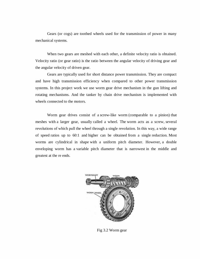
Worm gear drives consist of a screw-like worm (comparable to a pinion) that
meshes with a larger gear, usually called a wheel. The worm acts as a screw, several
revolutions of which pull the wheel through a single revolution. In this way, a wide range
of speed ratios up to 60:1 and higher can be obtained from a single reduction. Most
worms are cylindrical in shape with a uniform pitch diameter. However, a double
enveloping worm has a variable pitch diameter that is narrowest in the middle and
greatest at the re ends.
Fig 3.2 Worm gear

This configuration allows the worm to engage more teeth on the wheel, thereby
increasing load capacity. In worm-gear sets, the worm is most often the driving member.
However, a reversible worm-gear has the worm and wheel pitches so proportioned that
movement of the wheel rotates the worm. In most worm gears, the wheel has teeth
similar to those of a helical gear, but the tops of the teeth curve inward to envelop the
worm. As a result, the worm slides rather than rolls as it drives the wheel. Because of this
high level of rubbing between the worm and wheel teeth, the efficiency of worm gearing
is lower than other major gear types.
One major advantage of the worm gear is low wear, due mostly to the full-fluid
lubricant film that tends to be formed between tooth surfaces by the worm sliding action.
A continuous film that separates the tooth surfaces and prevents direct metal-to-
metal contact is typically provided by a relatively heavy oil, which is often
compounded with fatty or fixed oils such as acid less tallow oil. This adds film strength
to the lubricant and further reduces friction by increasing the oiliness of the fluid. The
detailed description about the worm gear drive mechanism is provided in the latter
chapters. As mentioned earlier all these mechanical gear drive mechanisms are driven by
the electric motors.
3.4 DC Motor :
An electric motor is a machine, which converts electrical energy into mechanical
energy. It is based on the principle that when a current-carrying conductor is placed in a
magnetic field, it experiences a mechanical force whose direction is given by Fleming’s
Left-hand rule and whose magnitude is given by
Force, F = B i L Newton
Where ‘B’ is the magnetic field in weber/m2.
‘i’ is the current in amperes and
‘L’ is the length of the coil in meter.
The force, current and the magnetic field are all in different directions.
If an Electric current flows through two copper wires that are between the poles of
a magnet, an upward force will move one wire up and a downward force will move the
other wire down.
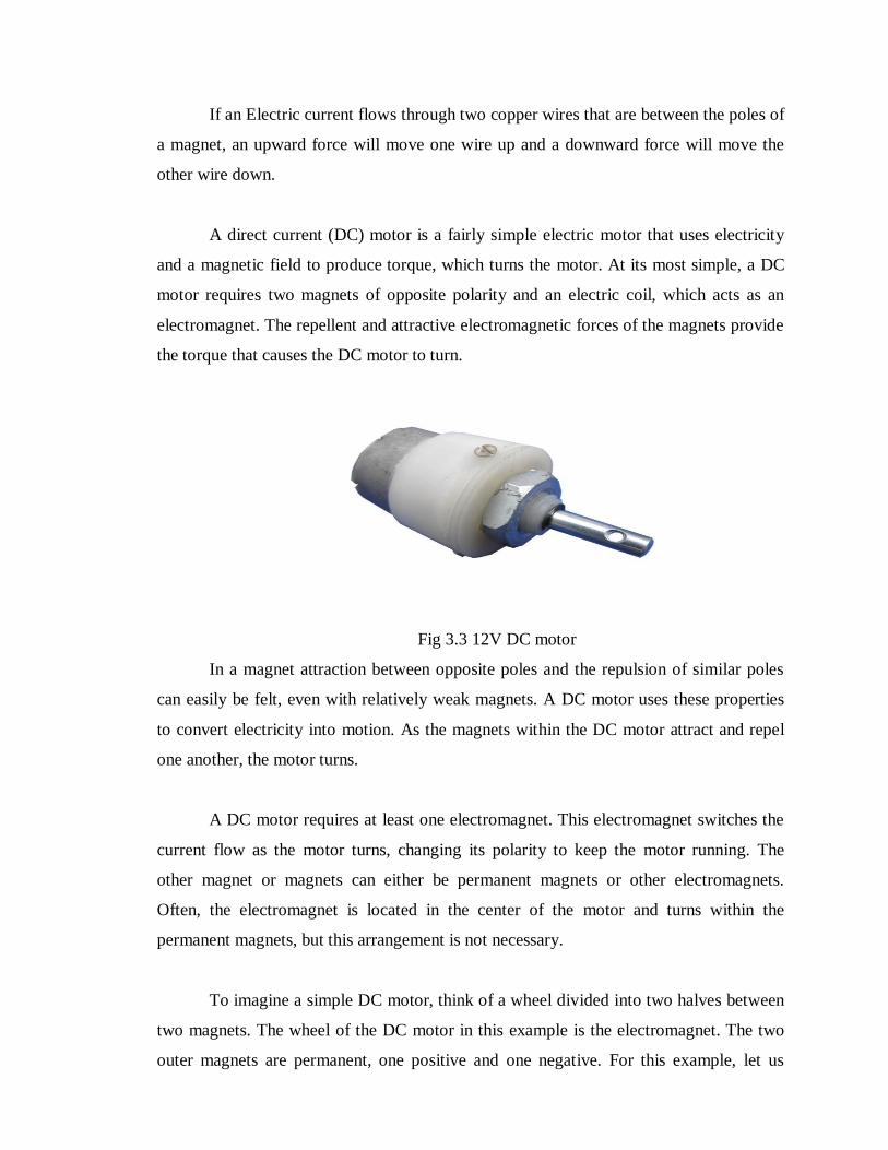
A direct current (DC) motor is a fairly simple electric motor that uses electricity
and a magnetic field to produce torque, which turns the motor. At its most simple, a DC
motor requires two magnets of opposite polarity and an electric coil, which acts as an
electromagnet. The repellent and attractive electromagnetic forces of the magnets provide
the torque that causes the DC motor to turn.
Fig 3.3 12V DC motor
In a magnet attraction between opposite poles and the repulsion of similar poles
can easily be felt, even with relatively weak magnets. A DC motor uses these properties
to convert electricity into motion. As the magnets within the DC motor attract and repel
one another, the motor turns.
A DC motor requires at least one electromagnet. This electromagnet switches the
current flow as the motor turns, changing its polarity to keep the motor running. The
other magnet or magnets can either be permanent magnets or other electromagnets.
Often, the electromagnet is located in the center of the motor and turns within the
permanent magnets, but this arrangement is not necessary.
To imagine a simple DC motor, think of a wheel divided into two halves between
two magnets. The wheel of the DC motor in this example is the electromagnet. The two
outer magnets are permanent, one positive and one negative. For this example, let us
assume that the left magnet is negatively charged and the right magnet is positively
charged.
Electrical current is supplied to the coils of wire on the wheel within the DC
motor. This electrical current causes a magnetic force. To make the DC motor turn, the
wheel must have be negatively charged on the side with the negative permanent magnet
and positively charged on the side with the permanent positive magnet. Because like
charges repel and opposite charges attract, the wheel will turn so that its negative side
rolls around to the right, where the positive permanent magnet is, and the wheel's positive
side will roll to the left, where the negative permanent magnet is. The magnetic force
causes the wheel to turn, and this motion can be used to do work.
When the sides of the wheel reach the place of strongest attraction, the electric
current is switched, making the wheel change polarity. The side that was positive
becomes negative, and the side that was negative becomes positive. The magnetic forces
are out of alignment again, and the wheel keeps rotating. As the DC motor spins, it
continually changes the flow of electricity to the inner wheel, so the magnetic forces
continue to cause the wheel to rotate.
DC motors are used for a variety of purposes, including electric razors, electric
car windows, and remote control cars. The simple design and reliability of a DC motor
makes it a good choice for many different uses, as well as a fascinating way to study the
effects of magnetic fields.
DC motors are widely used, inexpensive, small and poweful for their size. They
are most easy to control. One DC motor requires only two singals for its operation. They
are non-polarized, means you can reverse the voltage without any damage to motor. DC
motors have +ve and –ve leads. Connecting them to a DC voltage source moves motor in
one direction (clockwise) and by reversing the polarity, the DC motor will move in

opposite direction (counter clockwise). The maximum speed of DC motor is specified in
rpm (rotation per minute). It has two rpms: no load and loaded. The rpm is reduces when
moving a load or decreases when load increases. Other specifications of DC motors are
voltage and current ratings. Below table shows the specifications of the motor used in the
project.
Speed 30 RPM
Operating Voltage 12V DC
Operating Current 150milliAmps
Table 3.1 DC Motor Specifications
Speed of the motor can be changed by changing the applied voltage across motor.
DC motors don’t have enough torque to drive the mechanism directly by connecting
mechanism with it. The motor driving circuit is designed with L293D chip; this is
popularly known as ‘H’ bridge device generally used to drive the low power DC
motors.To drive these motors independently in both directions, drive sequence is
programmed depending up on the information gathered from the transmitter.
3.5 H-Bridge (General description) :
H-Bridge is an electronic circuit which enables a voltage to be applied on either
side of the load and the H-bridge DC motors allow the car to run backwards or forwards.
H-Bridge is a configuration of 4 switches, which switch in a specific manner to control
the direction of the current through the motor. Below figure shows simplified H-bridge as
switches. The states of these four switches can be changed in order to change the voltage
across the motor, of the current flow and the rotation of motor.
Fig 3.4 Basic Structure of an H-Bridg

In above figure, all switches are open and the motor terminals are disconnected
from the circuit. This state allows the motor to spin freely. If we open switches S1 & S4
and close S2 & S3 as in first part of below figure there will be current flow across the
circuit and motor will run. But if S1, S4 are close and S2, S3 are open, the voltage across
the motor will switch around and that will cause the motor to rotate in the opposite
direction. Below table summarizes the basic operation of the H-bridge depending upon
the voltage applied across the switches.
S1 S2 S3 S4 Result
1 0 0 1 Motor moves right
0 1 1 0 Motor moves left
0 0 0 0 Motor free runs
0 1 0 1 Motor brakes
1 0 1 0 Motor brakes
Table 3.2 H-Bridge Operation Summary
Fig 3.5 Two basic states of an H-Bridge
To control the speed and direction of the DC motor from the microcontroller, this
simple H-bridge will be of no use. H-bridge which makes use of transistors works best
for robotics projects. These transistors work as switch and they can control the current
flow in the motor easily. Below figure shows transistor as a switch.

Fig 3.6 Transistors as a Switch
The difference between the mechanical switch and the transistor switch is that
mechanical switch can be turned on or off mechanically but a transistors switch can be
turned on or off by applying small current at the base. For an NPN transistor, when a
small current of 20mA is applied to the base of the transistor, current will flow from
collector to emitter. In case of, for PNP transistor, the current will flow from emitter to
collector. For transistor to work as switch, the applied voltage at base needs to be higher
than collector voltage for NPN transistor and lower than collector voltage for PNP
transistor.
In this project, the dual H-bridge motor driver IC used is L293D. “The L293D is a
monolithic integrated, high voltage, high current, 4-channel driver”. The L293D supports
two DC motors. Pin 8 is voltage for the motors and pin 16 is the +5 voltage for the chip.
So with one IC we can interface two DC motors which can be controlled in both
clockwise and counter clockwise direction and if you have motor with fix direction of
motion then we can make use of all the four I/Os to connect up to four DC motors. First
motor is connected between pin 3 and 6. The motor is turned on by sending a high signal
to both the enable (pin 1) pin and one of the two direction pins, i.e. pin 2 or pin 7. To stop
motor, the enable pin is high and both pin 2 and pin 7 are low. L293D has output current
of 600mA and peak output current of 1.2A per channel. Moreover for protection of
circuit from back EMF output diodes are included within the IC. The output supply

(VCC2) has a wide range from 4.5V to 36V, which had made L293D a best choice for
DC motor driver.
Fig 3.7 DC Motor Control with H-Bridge
The same goes for the other side of the chip. When using two motors, the best
practice is to connect pins 2 and 15 togather and pin 7 and 10. above figure shows the
control of the DC motors with L293D and microcontroller signal.
Fig 3.8 L293D H Bridge (Motor Driver)

Motor drivers are the simplest modules that provide power amplification for low-
level control singals like PWM and direction supplied by the user.
Depending on the command signals given from the remote, the controller decodes
the information and takes decisions appropriately. The vehicle (robot) movement is
performed using two DC motors driven by a single H - Bridge IC. So four keys in the
remote control the tanker directions i.e., forward, backward, right and left. One more H –
Bridge IC is used to drive the two DC motors for controlling the gun direction in
rotational mechanism and lifting up and down present on the vehicle itself. Out of the two
DC motors, one motor is used to to lift the gun to certain height and the second DC motor
is used to rotate the gun to desired position. The DC motor is also to be rotated in the
reverse direction and by reversing the polarities, the motor rotates in the reverse direction
that is done by the controller through the H - Bridge IC’s. The mechanical movements of
the above mentioned mechanism using two DC motors is designed using gear drive
mechanisms for the required mechanical motions.
3.6 LIMIT SWITCHES :
In engineering a limit switch is a switch operated by the motion of a machine part
or presence of an object. They are used for control of a machine, as safety interlocks, or
to count objects passing a point. A limit switch is an electromechanical device that
consists of an actuator mechanically linked to a set of contacts. When an object comes
into contact with the actuator, the device operates the contacts to make or break an
electrical connection. Limit switches are used in a variety of applications and
environments because of their ruggedness, ease of installation, and reliability of
operation. They can determine the presence or absence, passing, positioning, and end of
travel of an object. They were first used to define the limit of travel of an object; hence
the name “Limit Switch.”
Standardized limit switches are industrial control components manufactured with
a variety of operator types, including lever, roller plunger, and whisker type. Limit
switches may be directly mechanically operated by the motion of the operating lever. A

reed switch may be used to indicate proximity of a magnet mounted on some moving
part. Proximity switches operate by the disturbance of an electromagnetic field, by
capacitance, or by sensing a magnetic field.
Rarely, a final operating device such as a lamp or solenoid valve will be directly
controlled by the contacts of an industrial limit switch, but more typically the limit switch
will be wired through a control relay, a motor contactor control circuit, or as an input to a
programmable logic controller.
Miniature snap-action switch may be used for example as components of such
devices as photocopiers or computer printers, to ensure internal components are in the
correct position for operation and to prevent operation when access doors are opened. A
set of adjustable limit switches are installed on a garage door opener to shut off the motor
when the door has reached the fully raised or fully lowered position. A numerical control
machine such as a lathe will have limit switches to identify maximum limits for machine
parts or to provide a known reference point for incremental motions.
In this project work also the mechanical movements are restricted through limit
switches and these entire limit switches are interfaced with the H – bridge IC’s as input
signals. As mentioned earlier, 2 limit switches are used to restrict the mechanical motion
by stopping the DC motors when reached to maximum extent. This limit switch is having
long lever and when little pressure is applied to the lever, switch will be activated
automatically. The mechanical transmission section that moves the excavating robot arm
in three degrees of freedom activates these switches at various levels. The following is
the diagram of limit switch.
Fig 3.9 Limit Switch
The limit switch shown above is having long lever, like this ten limit switches are
used, and they are arranged at different positions of the mechanical structure to control
the movement of mechanical transmission section. The motion of the motor in the form
mechanical movement, if it touches to the lever, than the switch is activated and
generates a logic signal to the DC motor. Based on this signals produced by these limit
switches, the mechanical movements of entire machine are restricted by the DC motors.
3.7 UM 3562 (GUN SOUNDS GENERATOR) :
General Description:
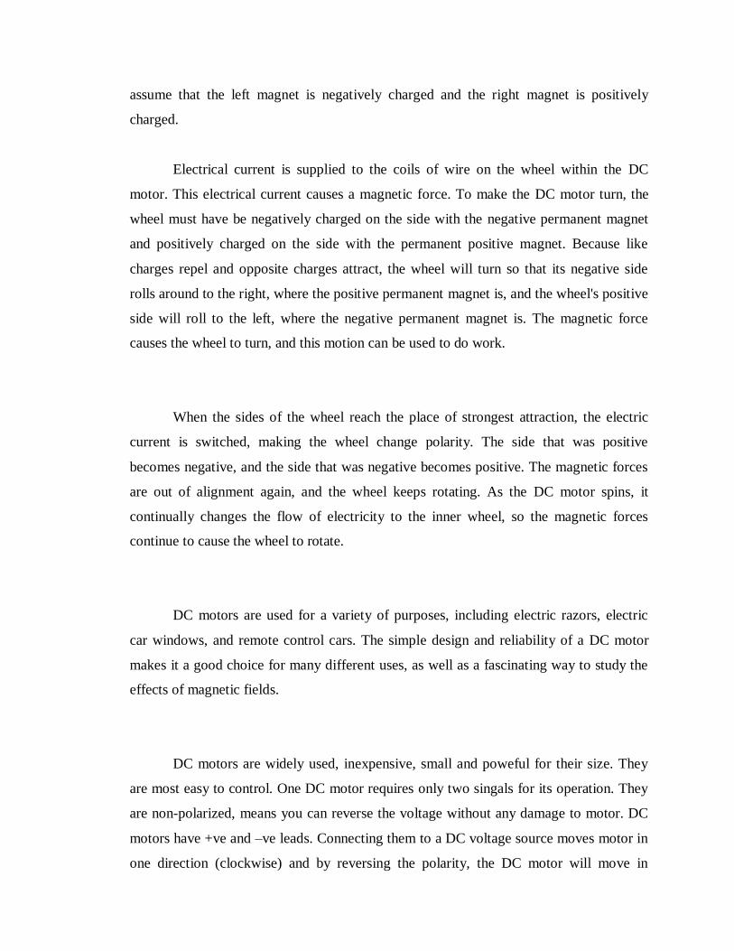
The IC UM 3562 used in this project is a low cost, low power CMOS LSI
designed for use in toy application. Since the IC includes oscillating and selector circuits,
a compact sound module can be constructed with only a few additional components. The
UM 3562 contains circuit to produce three gun sounds. The circuit constructed here has a
facility to adjust machine gun shooting rate. For this resistor R1 and R2 are given as
optional with dotted marking on PCB. If shooting rate is not to be adjusted then resistor
R1 and R2 may be omitted.
Fig 3.10 UM 3562

FEATURES:
Three sounds can be selected
1) Rifle Gun
2) Machine Gun
3) Laser Gun
Typical 3V operating voltage
RC Oscillator built-in
A magnetic speaker can be driven by connecting NPN transistor
Power ON reset
PIN DESCRIPTION
Pin No. Destination Description
1 OSC
This pin is used for testing in normal operation
the pin is open.
2 SEL Sound effect select pin.
3 VSS Negative Power Supply
4 TRI Trigger pin
5 OUTPUT Monotone Output
6 ADJ Normally open, may connect a resistor to ground
to adjust machine gun shoots rates.
7 NC No connection
8 VDD Positive power supply
Table 3.3 Pin description table

A relay is used to activate this chip when gun firing is to be done. The controller
control the operation of the relay depending on the key pressed in the remote in manual
operation. Else in the automatic mode of operation also, depending on the direction of the
hit target, the controller automatically rotates the gun to that particular direction and
activates this chip through the relay to fire.
3.8 Relay :
A relay is an electromagnetic switch, which can be used to make or break the
circuit. Here a relay is connected at the output of the microcontroller to control the gun
firing sound generator IC. The relay used here is having only one set of changing over
contact, when this relay is energized normally open contact gets closed and supply is
provided to the sound generator IC. When the same relay is de-energized, normally open
contact remains in open condition and supply is disconnected to the device. The contact
rating of the relay is 1.5 amps; less than 1.5 amps restrict so current flowing through the
contact. If any heavy load device is used, higher rating relay must be selected
accordingly.
A relay is an electrical switch that opens and closes under the control of another
electrical circuit. In the original form, the switch is operated by an electromagnet to open
or close one or many sets of contacts. These contacts can be either Normally Open (NO),
Normally Closed (NC), or change-over contacts. A relay is able to control an output
circuit of higher power than the input circuit, it can be considered to be, in a broad sense,
a form of an electrical amplifier. So a relay can be defined as an automatic
electromagnetic/electronic switch, which can be used to make or break the circuit.
The relay used in this project work is electro-magnetic/mechanical relay. The
electromagnetic relay is basically a switch (or a combination of switches) operated by the
magnetic force generated by a current flowing through a coil. Essentially, it consists of
four parts an electromagnet comprising a coil and a magnetic circuit, a movable armature,

a set of contacts, and a frame to mount all these components. However, very wide ranges
of relays have been developed to meet the requirements of the industry. This relay is
nothing but a switch, which operates electromagnetically. It opens or closes a circuit
when current through the coil is started or stopped. When the coil is energized armature
is attracted by the electromagnet and the contacts are closed. That is how the power is
applied to the signals (indicators). The construction of the typical relay contains a code
surrounded by a coil of copper wire. The core is mounted on a metal frame. The movable
part of the relay is called armature. When a voltage is applied to the coil terminals, the
current flowing through the coil produces a magnetic field in the core. In other words, the
core acts as an electromagnet and attracts the metal armature. When the armature is
attracted to the core, the magnetic path is from the core through armature, through the
frame, and back to the core. On removing the voltage the spring attached to the armature
returns the armature to its original position. In this position, there is a small air-gap in the
magnetic path. Hence, more power is needed to pull in the armature than that needed to
keep it held in the attracted position.
The electromagnetic relay, one of mankind’s first electrical device, was used
practically in telegraphy as early as 1850. The modern relay, properly applied, is one of
the most simple, effective and dependable component available. In the majority of
instances, it can achieve better reliability at lesser cost than an equivalent solid-state
complex type of relay. The term ‘relay’ was used for the first time to describe an
invention made by Samuel Morse in 1836. The device invented by Morse was a
“Telegraph Amplifying Electromagnetic Device” which enabled a small current flowing
in a coil to switch on a large current in another circuit and thus helped in “relay” of
signals.
A relay is a device that opens or closes an auxiliary circuit under some
predetermined condition in the main circuit. The object of a relay is generally to act as a
sort of electric magnifier, that is to say, it enables a comparatively weak current to bring
into operation a much stronger current. It also provides complete electrical isolation
between the controlling circuit and the controlled circuit. The relay is operated like a
switch to control the gun firing sound generator IC. The controller controls the operation
of the relay i.e., ON and OFF by which the device is also controlled.
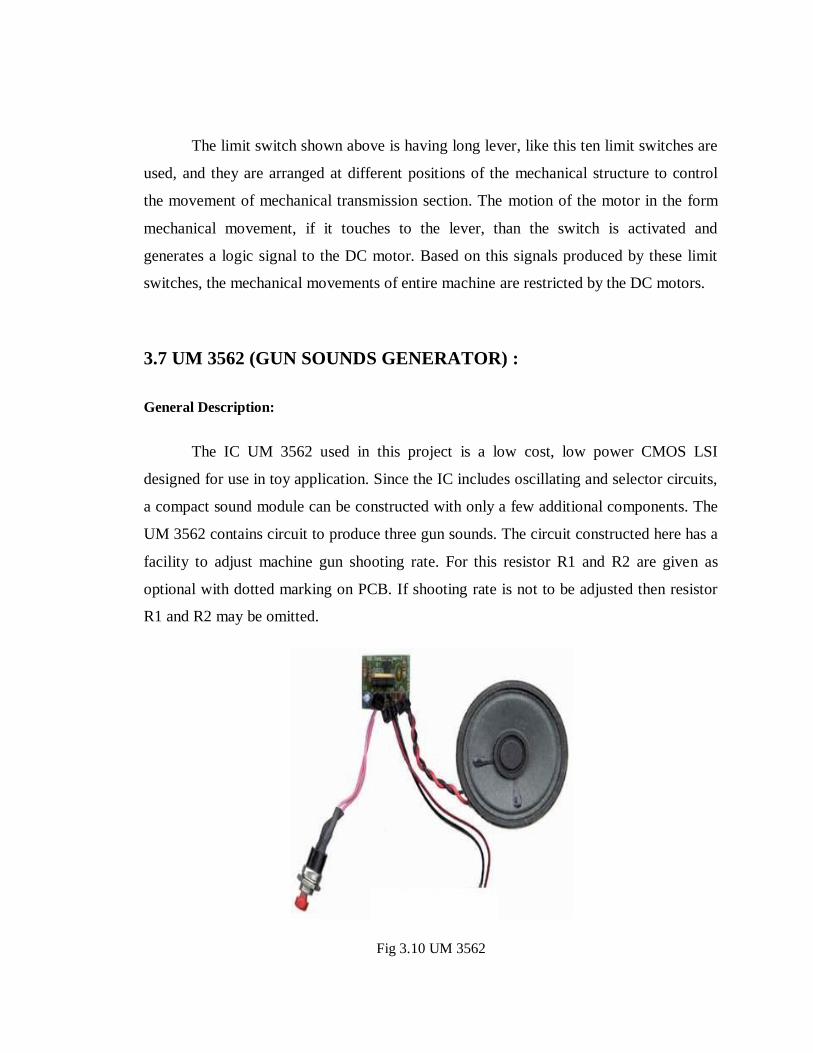
The relay contacts and the terminals are mounted on an insulated board. When no
current flows through the relay coil, the contact arm, or pole as it is called, mounted on
the armature, touches the “top” (N/C) contact. When the coil is energized by flow of
current, the armature along with the contact arm assembly moves downwards; so that the
contact arm touches the “bottom” (N/O) contact. When an electric current is flowing
through a relay coil, it is said to be energized, and when the current flow stops, the relay
is said to be de-energized. They have a set of parallel contacts, which are all pulled in
when the electromagnet pulls in the armature. On being energized, whether a relay makes
contact(s) or breaks them depends on the design of contact arrangements. Though the
contacts are open or close simultaneously, the sequence of operation cannot be
guaranteed in this of construction. To have a definite switching sequence, stacked
contacts are used.
Fig 3.11 Schematic of relay with contact
3.9 Automatic mode :
The mechanical construction of the war tanker is constructed with metal plates in
a hexagon shape. So the gun detects the hit target from all these six directions. Each
metal plate is also bent around 45 degrees to identify the hit targets from the air. So this
way six metal plates detects 12 directions i.e., six for the horizontal sideways and six
more for the aired targets hitting purpose. These metal plates are connected with positive
power supply of 5 volts and a thin metal mesh is placed individually over the metal plates
with some gap using spacers for all the 12 sides of the tanker. And these metal meshes
are connected to the controller like inputs to detect the target hit direction. If any target
hits, the mesh gets into contact with the metal plate by which the controller gets a logic
high signal to identify the direction of the hit target. So the controller automatically
controls the gun direction to the target hit direction and starts firing.
3.10 Power source :
The required power supply to drive the excavating robot is derived by 12V, 7.5
Ah (Ampere hour), rechargeable, lead acid heavy duty battery. Here we require three
different DC levels of +5V, +9V and +12V. The battery as it is delivering 12V is used to
drive the DC motors through the H Bridge IC’s, where as for the remaining electronic
circuitry consists of microcontroller, ADC, 555 timer chip, LCD and RF receiver requires
+5V constant source. The wireless video camera requires a constant regulated supply of
+9V DC. To generate a stable supply of +5V, 7805 three terminal voltage regulator chip
is used which provides constant supply, though the battery terminal voltage falls down to
8V. In the same way for deriving +9V, 7809 voltage regulator is used. The DC motors
are designed to operate at 12V DC and each motor consumes a maximum current of 150
milli-amps, there by four motors for the robot movement together consumes 600 milli-
amps. Likewise by calculating the current drawn by the entire circuit, the backup time of
the battery can be calculated. The relation for calculating the backup time is given as:
The battery backup time = battery rating in Ah/ consumed energy (current drawn by the
entire circuit in Amps).
CHAPTER – 4
MICRO CONTROLLERS
4.1 INTRODUCTION :
A Micro controller consists of a powerful CPU tightly coupled with memory,
various I/O interfaces such as serial port, parallel port timer or counter, interrupt
controller, data acquisition interfaces-Analog to Digital converter, Digital to Analog
converter, integrated on to a single silicon chip. If a system is developed with a
microprocessor, the designer has to go for external memory such as RAM, ROM,
EPROM and peripherals.
But controller is provided all these facilities on a single chip. Development of a
Micro controller reduces PCB size and cost of design. One of the major differences
between a Microprocessor and a Micro controller is that a controller often deals with bits
not bytes as in the real world application.
Intel has introduced a family of Micro controllers called the MCS-51.The
microcontroller plays the major role in any embedded project. In this my project we use
three microcontrollers they are made by the ATMEL Company. In which two are
AT89C51/52 and the other is AT 89C2051.
4.2 Necessity of microcontrollers :
Microprocessors brought the concept of programmable devices and made many
applications of intelligent equipment. Most applications, which do not need large amount
of data and program memory, tended to be costly.
The microprocessor system had to satisfy the data and program requirements so;
sufficient RAM and ROM are used to satisfy most applications .The peripheral control
equipment also had to be satisfied. Therefore, almost all-peripheral chips were used in the
design. Because of these additional peripherals cost will be comparatively high.
An example:
8085 chip needs an Address latch for separating address from multiplex address
and data.32-KB RAM and 32-KB ROM to be able to satisfy most applications. As also
Timer / Counter, Parallel programmable port, Serial port, and Interrupt controller are
needed for its efficient applications.
In comparison a typical Micro controller 8051 chip has all that the 8051
board has except a reduced memory i.e; 4K bytes of ROM as compared to
32-KB, 128 Bytes of RAM as compared to 32-KB.
Typical Micro controller has all the following features
8/16/32 CPU
Instruction set rich in I/O & bit operations.
One or more I/O ports.
One or more timer/counters.
One or more interrupt inputs and an interrupt controller
One or more serial communication ports.
Analog to Digital /Digital to Analog converter
One or more PWM output
Network controlled interface
4.3 ADVANTAGES OF MICROCONTROLLER :
1. If system is developed with a microprocessor, the designer has to go for external
memory such as RAM, ROM or EPROM and peripherals and hence the size of PCB will
be large enough to hold all the required peripherals. But, the micro controller has got all
this peripheral facility on a single chip o development of a similar system with a micro
controller reduces PCB size and cost of the design.
2. One of the major differences between a micro controller and a microprocessor is that a
controller often deals with bits, not bytes as in the real world application, for example
switch contacts can only be open or close, indicators should be lit or dark and motors can
be either turned on or off and so forth.
3. On comparing a board full of chips (Microprocessors) which is bulky with one chip
with all components in it (Micro controller) which is very simple.
4. Lots of Microprocessor circuitry and program to debug. In Micro controller there is no
Microprocessor circuitry to debug.
5. As we have observed Microprocessors need a lot of debugging at board level and at
program level, whereas, Micro controller do not have the excessive circuitry and the
built-in peripheral chips are easier to program for operation. So peripheral devices like
Timer/Counter, Parallel programmable port, Serial Communication Port, Interrupt
controller and so on, which were most often used were integrated with the
Microprocessor to present the Micro controller .RAM and ROM also were integrated in
the same chip. The ROM size was anything from 256 bytes to 32Kb or more. RAM was
optimized to minimum of 64 bytes to 256 bytes or more.
4.4 AT89C51 TYPE MICRO CONTROLLER :
The system requirements and control specifications clearly rule out the use of 16,
32 or 64 bit micro controllers or microprocessors. Systems using these may be earlier to
implement due to large number of internal features. They are also faster and more reliable
but, the above application is satisfactorily served by 8-bit micro controller. Using an
inexpensive 8-bit Microcontroller will doom the 32-bit product failure in any competitive
market place.
Coming to the question of why to use P89V51RD2 of all the 8-bit Microcontroller
available in the market the main answer would be because it has 64 kB Flash and 1024
bytes of data RAM. . The Flash program memory supports both parallel programming
and in serial In-System Programming (ISP). The P89V51RD2 is also In-Application
Programmable (IAP), allowing the Flash program memory to be reconfigured even while
the application is running.

The generic 8051 architecture supports a Harvard architecture, which contains two
separate buses for both program and data. So, it has two distinctive memory spaces of
64K X 8 size for both programmed and data.
It is based on an 8 bit central processing unit with an 8 bit Accumulator and
another 8 bit B register as main processing blocks. Other portions of the architecture
include few 8 bit and 16 bit registers and 8 bit memory locations.
4.5 FEATURES OF 8051 ARCHITECTURE :
1) Optimized 8 bit CPU for control applications and extensive Boolean
processing capabilities.
2) 64K Program Memory address space.
3) 64K Data Memory address space.
4) 128 bytes of on chip data memory out of which 4 register banks, each
containing 8 registers, 16 bytes, which are addressed at the bit level and 80 bytes
of general- purpose data memory.
5) 32 Bi-directional and individually addressable I/O lines.
6) Two 16 bit timer/counters.
7) Full Duplex UART.
8) 6-source / 5-vector interrupt structure with priority levels.
9) On chip clock oscillator.
Now we may be wondering about the non-mentioning of memory space
meant for the program storage, the most important part of any embedded
controller. Originally this 8051 architecture was introduced with on-chip, ‘one
time programmable’ version of Program Memory of size 4K X 8.
Intel delivered all these microcontrollers (8051) with user’s program fused
inside the device. The memory portion was mapped at the lower end of the

Program Memory area. But, after getting devices, customers couldn’t change
anything in their program code, which was already made available inside during
device fabrication.
The 8051 architecture consists of these specific features:
Eight –bit CPU with registers A (the accumulator) and B
Sixteen-bit program counter (PC) and data pointer (DPTR)
Eight- bit stack pointer (PSW)
Eight-bit stack pointer (Sp)
Internal ROM or EPROM (8751) of 0(8031) to 4K (8051)
Internal RAM of 128 bytes:
Thirty –two input/output pins arranged as four 8-bit ports:p0-p3
Two 16-bit timer/counters: T0 and T1
Full duplex serial data receiver/transmitter: SBUF
Control registers: TCON, TMOD, SCON, PCON, IP, and IE
Two external and three internal interrupts sources.
Oscillator and clock circuits.
4.6 PIN DIAGRAM :
Fig 4.1 Pin diagram of 89C51 IC

Fig 4.2 Functional block diagram of micro controller
4.7 PORT 3 PINS ALTERNATIVE FUNCTIONS :
All four ports in the 89C51 are bidirectional. Each consists of a latch (Special
Function Registers P0 through P3), an output driver, and an input buffer. The output
drivers of Ports 0 and 2, and the input buffers of Port 0, are used in accesses to external
memory. In this application, Port 0 outputs the low byte of the external memory address,
time-multiplexed with the byte being written or read. Port 2 outputs the high byte of the
external memory address when the address is 16 bits wide. Otherwise, the Port 2 pins
continue to emit the P2 SFR content.
All the Port 3 pins are multifunctional. They are not only port pins, but also serve
the functions of various special features as listed below:
Port Pin Alternate Function
P3.0 RxD (serial input port)
P3.1 TxD (serial output port)
P3.2 INT0 (external interrupt)
P3.3 INT1 (external interrupt)
P3.4 T0 (Timer/Counter 0 external input)
P3.5 T1 (Timer/Counter 1 external input)
P3.6 WR (external Data Memory write strobe)
P3.7 RD (external Data Memory read strobe)
VCC Supply voltage
VSS Circuit ground potential
4.7.1 The 8051 Oscillator and Clock :
The heart of the 8051 circuitry that generates the clock pulses by which all the
internal all internal operations are synchronized. Pins XTAL1 And XTAL2 is provided
for connecting a resonant network to form an oscillator. Typically a quartz crystal and
capacitors are employed. The crystal frequency is the basic internal clock frequency of
the microcontroller. The manufacturers make 8051 designs that run at specific minimum
and maximum frequencies typically 1 to 16 MHz.
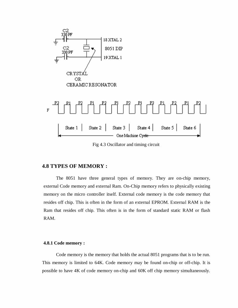
Fig 4.3 Oscillator and timing circuit
4.8 TYPES OF MEMORY :
The 8051 have three general types of memory. They are on-chip memory,
external Code memory and external Ram. On-Chip memory refers to physically existing
memory on the micro controller itself. External code memory is the code memory that
resides off chip. This is often in the form of an external EPROM. External RAM is the
Ram that resides off chip. This often is in the form of standard static RAM or flash
RAM.
4.8.1 Code memory :
Code memory is the memory that holds the actual 8051 programs that is to be run.
This memory is limited to 64K. Code memory may be found on-chip or off-chip. It is
possible to have 4K of code memory on-chip and 60K off chip memory simultaneously.
If only off-chip memory is available then there can be 64K of off chip ROM. This is
controlled by pin provided as EA.
4.8.2 Internal RAM
The 8051 have a bank of 128 bytes of internal RAM. The internal RAM is found
on-chip. So it is the fastest Ram available. And also it is most flexible in terms of reading
and writing. Internal Ram is volatile, so when 8051 is reset, this memory is cleared. 128
bytes of internal memory are subdivided. The first 32 bytes are divided into 4 register
banks. Each bank contains 8 registers. Internal RAM also contains 128 bits, which are
addressed from 20h to 2Fh. These bits are bit addressed i.e. each individual bit of a byte
can be addressed by the user. They are numbered 00h to 7Fh. The user may make use of
these variables with commands such as SETB and CLR.
4.9 SPECIAL FUNCTION REGISTERED MEMORY
Special function registers are the areas of memory that control specific
functionality of the 8051 micro controller.
1.Accumulator (0E0h) :
As its name suggests, it is used to accumulate the results of large no of
instructions. It can hold 8 bit values.
2.B register (0F0h) :
The B register is very similar to accumulator. It may hold 8-bit value. The b
register is only used by MUL AB and DIV AB instructions. In MUL AB the higher byte
of the product gets stored in B register. In div AB the quotient gets stored in B with the
remainder in A.
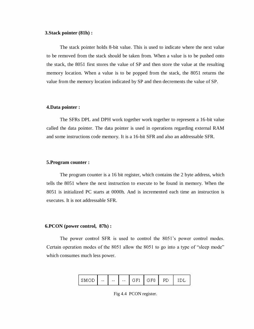
3.Stack pointer (81h) :
The stack pointer holds 8-bit value. This is used to indicate where the next value
to be removed from the stack should be taken from. When a value is to be pushed onto
the stack, the 8051 first stores the value of SP and then store the value at the resulting
memory location. When a value is to be popped from the stack, the 8051 returns the
value from the memory location indicated by SP and then decrements the value of SP.
4.Data pointer :
The SFRs DPL and DPH work together work together to represent a 16-bit value
called the data pointer. The data pointer is used in operations regarding external RAM
and some instructions code memory. It is a 16-bit SFR and also an addressable SFR.
5.Program counter :
The program counter is a 16 bit register, which contains the 2 byte address, which
tells the 8051 where the next instruction to execute to be found in memory. When the
8051 is initialized PC starts at 0000h. And is incremented each time an instruction is
executes. It is not addressable SFR.
6.PCON (power control, 87h) :
The power control SFR is used to control the 8051’s power control modes.
Certain operation modes of the 8051 allow the 8051 to go into a type of “sleep mode”
which consumes much less power.
Fig 4.4 PCON register.
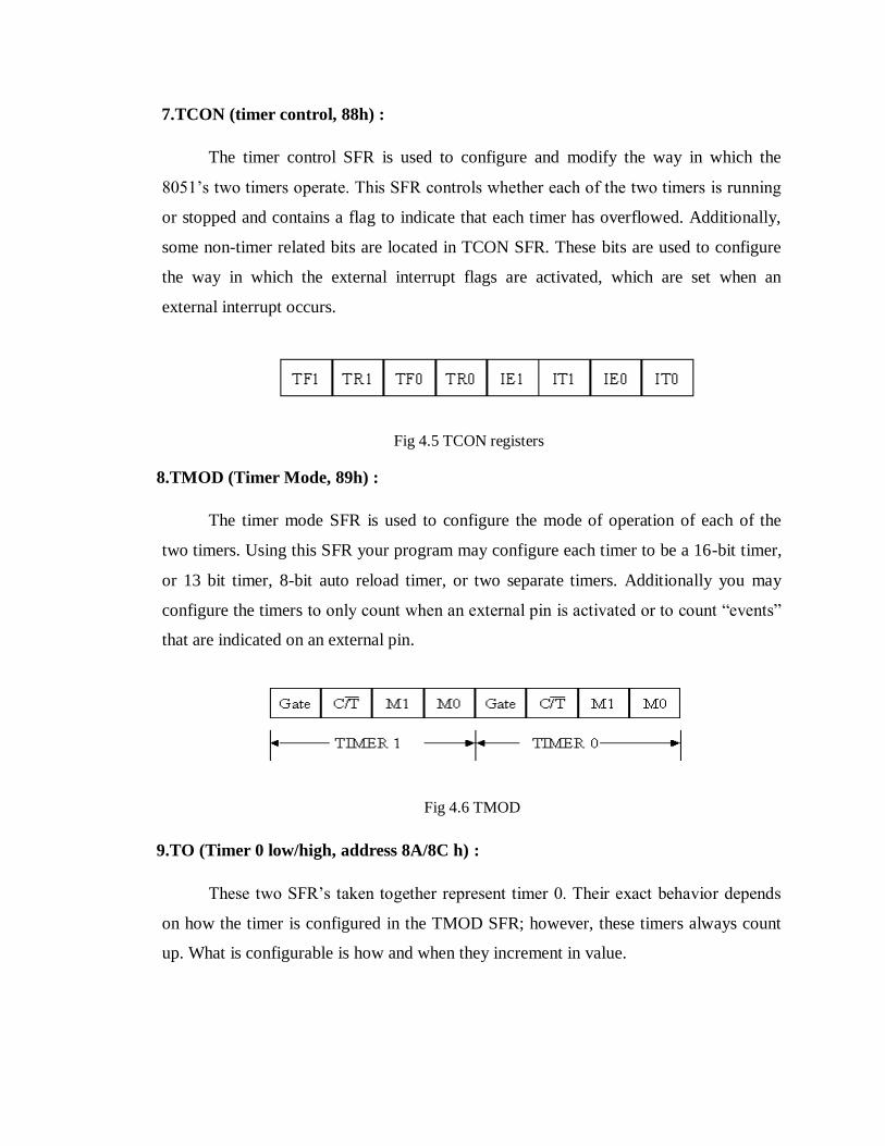
7.TCON (timer control, 88h) :
The timer control SFR is used to configure and modify the way in which the
8051’s two timers operate. This SFR controls whether each of the two timers is running
or stopped and contains a flag to indicate that each timer has overflowed. Additionally,
some non-timer related bits are located in TCON SFR. These bits are used to configure
the way in which the external interrupt flags are activated, which are set when an
external interrupt occurs.
Fig 4.5 TCON registers
8.TMOD (Timer Mode, 89h) :
The timer mode SFR is used to configure the mode of operation of each of the
two timers. Using this SFR your program may configure each timer to be a 16-bit timer,
or 13 bit timer, 8-bit auto reload timer, or two separate timers. Additionally you may
configure the timers to only count when an external pin is activated or to count “events”
that are indicated on an external pin.
Fig 4.6 TMOD
9.TO (Timer 0 low/high, address 8A/8C h) :
These two SFR’s taken together represent timer 0. Their exact behavior depends
on how the timer is configured in the TMOD SFR; however, these timers always count
up. What is configurable is how and when they increment in value.

10.T1 (Timer 1 Low/High, address 8B/ 8D h) :
These two SFRs, taken together, represent timer 1. Their exact behavior depends
on how the timer is configured in the TMOD SFR; however, these timers always count
up.
11.P0 (Port 0, address 90h, bit addressable) :
This is port 0 latch. Each bit of this SFR corresponds to one of the pins on a micro
controller. Any data to be outputted to port 0 is first written on P0 register. For e.g., bit 0
of port 0 is pin P0.0, bit 7 is pin p0.7. Writing a value of 1 to a bit of this SFR will send a
high level on the corresponding I/O pin whereas a value of 0 will bring it to low level.
12.P1 (port 1, address 90h, bit addressable) :
This is port latch1. Each bit of this SFR corresponds to one of the pins on a micro
controller. Any data to be outputted to port 0 is first written on P0 register. For e.g., bit 0
of port 0 is pin P1.0, bit 7 is pin P1.7. Writing a value of 1 to a bit of this SFR will send
a high level on the corresponding I/O pin whereas a value of 0 will bring it to low level.
13.P2 (port 2, address 0A0h, bit addressable) :
This is a port latch2. Each bit of this SFR corresponds to one of the pins on a
micro controller. Any data to be outputted to port 0 is first written on P0 register. For e.g.,
bit 0 of port 0 is pin P2.0, bit 7 is pin P2.7. Writing a value of 1 to a bit of this SFR will
send a high level on the corresponding I/O pin whereas a value of 0 will bring it to low
level.
14.P3 (port 3, address B0h, bit addressable) :
This is a port latch3. Each bit of this SFR corresponds to one of the pins on a
micro controller. Any data to be outputted to port 0 is first written on P0 register. For e.g.,
bit 0 of port 0 is pin P3.0, bit 7 is pin P3.7. Writing a value of 1 to a bit of this SFR will
send a high level on the corresponding I/O pin whereas a value of 0 will bring it to low
level.

15.IE (interrupt enable, 0A8h) :
The Interrupt Enable SFR is used to enable and disable specific interrupts. The
low 7 bits of the SFR are used to enable/disable the specific interrupts, where the MSB
bit is used to enable or disable all the interrupts. Thus, if the high bit of IE is 0 all
interrupts are disabled regardless of whether an individual interrupt is enabled by setting
a lower bit.
Fig 4.7 IE Registers
16.IP (Interrupt Priority, 0B8h) :
The interrupt priority SFR is used to specify the relative priority of each interrupt.
On 8051 an interrupt may be either low or high priority. An interrupt may interrupt
interrupts. For e.g., if we configure all interrupts as low priority other than serial
interrupt. The serial interrupt always interrupts the system, even if another interrupt is
currently executing. However, if a serial interrupt is executing no other interrupt will be
able to interrupt the serial interrupt routine since the serial interrupt routine has the
highest priority.
Fig 4.8 IP registers
17.PSW (Program Status Word, 0D0h) :
The program Status Word is used to store a number of important bits that are set
and cleared by 8051 instructions. The PSW SFR contains the carry flag, the auxiliary
carry flag, the parity flag and the overflow flag. Additionally, it also contains the register

bank select flags, which are used to select, which of the “R” register banks currently in
use.
Fig 4.9 PSW registers
18.SBUF (Serial Buffer, 99h) :
SBUF is used to hold data in serial communication. It is physically two registers.
One is writing only and is used to hold data to be transmitted out of 8051 via TXD. The
other is read only and holds received data from external sources via RXD. Both mutually
exclusive registers use address 99h.
19.I/O Ports :
One major feature of a microcontroller is the versatility built into the input/output
(I/O) circuits that connect the 8051 to the outside world. The main constraint that limits
numerous functions is the number of pins available in the 8051 circuit. The DIP had 40
pins and the success of the design depends on the flexibility incorporated into use of
these pins. For this reason, 24 of the pins may each used for one of the two entirely
different functions which depend, first, on what is physically connected to it and, then, on
what software programs are used to “program” the pins.
20.PORT 0 :
Port 0 pins may serve as inputs, outputs, or, when used together, as a bi
directional low-order address and data bus for external memory. To configure a pin as
input, 1 must be written into the corresponding port 0 latch by the program. When used
for interfacing with the external memory, the lower byte of address is first sent via
PORT0, latched using Address latch enable (ALE) pulse and then the bus is turned
around to become the data bus for external memory.

21.PORT 1 :
Port 1 is exclusively used for input/output operations. PORT 1 pins have no dual
function. When a pin is to be configured as input, 1 is to be written into the
corresponding Port 1 latch.
22.PORT 2 :
Port 2 may be used as an input/output port. It may also be used to supply a high –
order address byte in conjunction with Port 0 low-order byte to address external memory.
Port 2 pins are momentarily changed by the address control signals when supplying the
high byte a 16-bit address. Port 2 latches remain stable when external memory is
addressed, as they do not have to be turned around (set to 1) for data input as in the case
for Port 0.
23.PORT 3 :
Port 3 may be used to input /output port. The input and output functions can be
programmed under the control of the P3 latches or under the control of various special
function registers. Unlike Port 0 and Port 2, which can have external addressing functions
and change all eight-port b se, each pin of port 3 maybe individually programmed to be
used as I/O or as one of the alternate functions. The Port 3 alternate uses are:
Pin (SFR) Alternate Use
P3.0-RXD (SBUF) Serial data input
P3.1-TXD (SBUF) Serial data output
P3.2-INTO 0 (TCON.1) External interrupt 0
P3.3 - INTO 1 (TCON.3) External interrupt 1
P3.4 - T0 (TMOD) External Timer 0 input
P3.5 – T1 (TMOD) External timer 1 input
P3.6 - WR External memory write pulse
P3.7 - RD External memory read pulse
Table 4.1 Port 3 Alternate Uses

4.10 INTERRUPTS :
Interrupts are hardware signals that are used to determine conditions that exist in
external and internal circuits. Any interrupt can cause the 8051 to perform a hardware
call to an interrupt –handling subroutine that is located at a predetermined absolute
address in the program memory.
Five interrupts are provided in the 8051. Three of these are generated
automatically by the internal operations: Timer flag 0, Timer Flag 1, and the serial port
interrupt (RI or TI) Two interrupts are triggered by external signals provided by the
circuitry that is connected to the pins INTO 0 and INTO1. The interrupts maybe enable or
disabled, given priority or otherwise controlled by altering the bits in the Interrupt
Enabled (IE) register, Interrupt Priority (IP) register, and the Timer Control (TCON)
register. . These interrupts are mask able i.e. they can be disabled. Reset is a non
maskable interrupt which has the highest priority. It is generated when a high is applied
to the reset pin. Upon reset, the registers are loaded with the default values.
Each interrupt source causes the program to do store the address in PC onto the
stack and causes a hardware call to one of the dedicated addresses in the program
memory. The appropriate memory locations for each for each interrupt are as follows:
Interrupt Address
RESET 0000
IE0 (External interrupt 0) 0003
TF0 (Timer 0 interrupt) 000B
IE1 (External interrupt 1) 0013
TF1 (Timer 1 interrupt) 001B
SERIAL 0023
Table 4.2 Interrupts

CHAPTER – 5
SOFTWARE DESCRIPTION
In our project we used software that is Keil micro vision for the simulation of the
program.
5.1 KEIL SOFTWARE :
Keil development tools for the 8051 Microcontroller Architecture support every
level of software developer from the professional applications engineer to the student just
learning about embedded software.
The industry-standard Keil C Compilers, Macro Assemblers, Debuggers, Real-
time Kernels, Single-board Computers, and Emulators support all 8051 derivatives and
help you get your projects completed on schedule.
5.2 SIMULATION :
The µVision Simulator allows you to debug programs using only your PC using
simulation drivers provided by Keil and various third-party developers. A good
simulation environment, like µVision, does much more than simply simulate the
instruction set of a microcontroller — it simulates your entire target system including
interrupts, startup code, on-chip peripherals, external signals, and I/O.
5.3 SOFTWARE FOR EXECUTION OF MICROCONTROLLER
PROGRAMS :

Keil development tools for the MC architecture support every level of software
developer from the professional applications engineer to the student just learning about
embedded software development.
The industry-standard Keil-C compilers, macro assemblers, debuggers, real, time
Kernels, Single-board computers and emulators support all microcontroller derivatives
and help you to get more projects completed on schedule. The Keil software development
tools are designed to solve the complex Problems facing embedded software developers.
Those are listed below.
5.4 PROBLEMS FACED BY EMBEDDED SOFTWARE
DEVELOPERS :
1. When starting a new project, simply select the microcontroller you the device
database and the µvision IDE sets all compiler, assembler, linker, and memory
options for you.
2. The Keil µ Vision debugger accurately simulates on-chip peripherals (PC, CAN,
UART, SPI, Interrupts, I/O ports, A/D converter, D/A converter and PWM
modules)of your aver device.
3. Simulation helps you understand h/w configurations and avoids time wasted on
setup problems. Additionally, with simulation, you can write and test applications
before target h/w is available.
4. When you are ready to begin testing your s/w application with target h/w, use the
MON51, MON390, MONADI, or flash MON51 target monitors, the ISD51 In-
System Debugger, or the ULINK USB-JTAG adapter to download and test
program code on your target system.

CHAPTER-6
SCOPE OF DEVELOPMENT
For the human operator to command the unmanned systems, technologies that
need to be mastered include artificial intelligence, radio-frequency technology and micro-
controllers. This prototype model resembles the actual idea of our project. The main aim
behind this project are mentioned below:
1. An army tanker which is controlled by remote.
2. It’s an un-manned war tanker.
3. Manually and Automatic controlled.
4. Self defending.
5. Self attacking.
6. Live visual coverage of war.
7. 360 degrees rotation of main gun.
8. Min.. speed 35mph.
9. 3 secondary machine guns.
10. Auto angle adjustment of main gun.
11. 5Ghz transmitter and receiver.
12. 6 DOF.
13. Highly Withstood.
14. Long distance working.
15. Sustainable in all weather conditions.
The need of this UGV (Un-manned Ground Vehicles) was primarily the
protection of the soldiers. The life of a human is more precious than a war tanker. Since
this systems are highly accurate in attacking the targets the surroundings are left
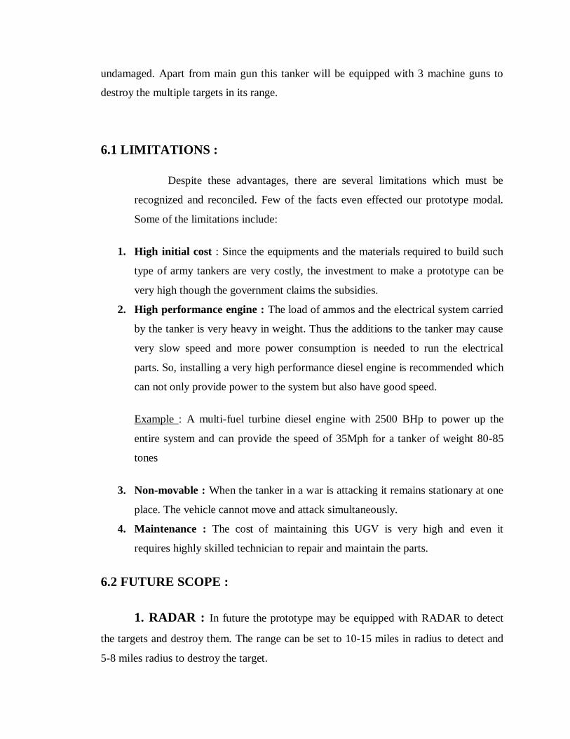
undamaged. Apart from main gun this tanker will be equipped with 3 machine guns to
destroy the multiple targets in its range.
6.1 LIMITATIONS :
Despite these advantages, there are several limitations which must be
recognized and reconciled. Few of the facts even effected our prototype modal.
Some of the limitations include:
1. High initial cost : Since the equipments and the materials required to build such
type of army tankers are very costly, the investment to make a prototype can be
very high though the government claims the subsidies.
2. High performance engine : The load of ammos and the electrical system carried
by the tanker is very heavy in weight. Thus the additions to the tanker may cause
very slow speed and more power consumption is needed to run the electrical
parts. So, installing a very high performance diesel engine is recommended which
can not only provide power to the system but also have good speed.
Example : A multi-fuel turbine diesel engine with 2500 BHp to power up the
entire system and can provide the speed of 35Mph for a tanker of weight 80-85
tones
3. Non-movable : When the tanker in a war is attacking it remains stationary at one
place. The vehicle cannot move and attack simultaneously.
4. Maintenance : The cost of maintaining this UGV is very high and even it
requires highly skilled technician to repair and maintain the parts.
6.2 FUTURE SCOPE :
1. RADAR : In future the prototype may be equipped with RADAR to detect
the targets and destroy them. The range can be set to 10-15 miles in radius to detect and
5-8 miles radius to destroy the target.

2. Artificial intelligence : Though its automatic, it needs a operator to move
the vehicle in different directions. These defect can be solved in future by implanting the
artificial intelligence.
3. Cameras : By installing cameras (Normal and night vision), the army can
get the live visuals of the war in day and in the night. Which can even helpful to detect
the enemy locations from a long range.
4. Additional ammo : With multiple ammo load carrying capacity, this tanker
can alone destroy multiple targets in the war. Since the main gun alone can’t fire missiles
back to back, installing 3 machine guns of long range can be beneficial in short range
attack and even to destroy multiple moving targets simultaneously.
5. Design and analysis : Further modifications in design and analysis can
make UGVs very powerful, durable and reliable with the advancement in technology in
future.
6. Material usage : By researching and developing a new material which can
withstand high collisions and are also not very heavy, the UGVs can made more resistible
to the land mines, hand granite, bazooka/man-portable missiles etc,.
7. High frequency receivers : By using the high frequency transmitter and
receiver, the UGVs can be operated from longer ranger say from about 10 miles away
from the controller.
The key to mastering unmanned warfare would include the complex tasks
of cross-selecting the technological components and integrating them into our military
hardware. The selected components should be seen as capabilities a country's armed
forces and defense industries must master, for they constitute the very essence of its
future fighting capabilities.

CONCLUSION
The project work is designed and developed successfully. For the demonstration
purpose, a prototype module is constructed; and the results are found to be satisfactory.
Since it is a prototype module, a simple war tanker is constructed, which can be used for
many applications. In this concept the warfare vehicle is controlled by a remote that will
be operated by the operator and also has the provision to operate automatically. The
triggering of the gun can also be done through the remote by which the gun sound
simulator IC produces the gun shot sensation.
The employment of unmanned platforms in the battlefield serves not only to
overcome the constraints arising from manpower and resource shortages, but also
increases the operational capability of a fighting force. They will provide tangible
increases in combat range, firepower, speed, element of surprise, command and control,
etc. As unmanned warfare and the mastery of unmanned technology will become
increasingly important parts of a nation's strategic architecture, here armed forces and
defense industries will need to pay appropriate attention to this aspect of warfare.
While designing and developing this proto type module, we have consulted few
experts those who are having knowledge in Mechatronics, and these professionals
working at different organizations belongs to Hyderabad helped us while fabricating this
project work. Since it is a prototype module, much amount is not invested. The whole
machine is constructed with locally available components, especially the mechanical
components used in this project work are procured from mechanical fabricators and they
are not exactly up to the requirement. Some of the modifications must be carried out in
design to make it as real working system.
REFERENCES:
The following are the references made during the development of this project
work.
Text Books:
1. Mechatronics – Electronic Control Systems in Mechanical and electrical Engineering
– By: W. Bolton
2. Mechatronics – By HMT Limited
3. Mechanism and Machine Theory By: J.S. Rao, R.V. Dukkipati
4. Industrial Robotics – Technology, Programming, & Applications. By: MIKELL P.
GROOVER, MITCHELL WEISS, ROGER
5. Electronic Circuit guide book – Sensors – By JOSEPH J.CARR
6. Linear Integrated Circuits – By: D. Roy Choudhury, Shail Jain
7. The concepts and Features of Micro-controllers - By: Raj Kamal
8. The 8051 Micro-controller Architecture, programming & Applications - By: Kenneth
J. Ayala
9. Programming and Customizing the 8051 Micro-controller - By: Myke Predko
10. The IC 555 Timer Applications Source book - By: HOWARD M. BERLIN
Catalogs:
1. TEXAS - LINEAR IC’s manual
2. SIGNETICS - DIGITAL IC’s manual
Web Links :
1. http://www.precisionmicrodrives.com/
2. http://en.wikipedia.org/wiki/Tank_destroyer
3. http://en.wikipedia.org/wiki/Future_Combat_Systems_manned_ground_vehicles#Mo
unted_combat_system
4. http://www.defense-update.com/features/du-1-04/feature-armor-protection.htm
5. http://www.armedforces-
int.com/news/electrified_vehicle_armour_could_deflect_weapons.html