Embed Size (px)
Citation preview

t
Programming Unit
Pocket Reference
FA4-41-216 Ed793
Technical Manuals Online! - http://www.tech-man.com

Technical Manuals Online! - http://www.tech-man.com

TABLE OF CONTENTS
PROGRAMMING UNIT FUNCTION KEYS.. ....... .l _ PROGRAM DOWNLOAD TO THE 4100 PANEL ........................................................ .3
Download Procedure for 4100 Systems with the 562-771 Master Controller ............... .3
Program Download to the 4100+ or UT CFIG “Flash” EPROM.. ............................ .5
Program Download to the 4020 CFIG “Flash” EPROM ............................................. .6
Other 4100 Programming Procedures.. ............ .7 Building a Job.. ........................................... .7 Programming (Burning) a CFIG
PROM Chip.. ........................................... .8 DIGITAL PSEUDO POINTS.. .............................. 10 ANALOG PSEUDO POINTS .............................. 18 POINT LIST SUMMARY.. .................................. .24 POINT LIST GENERATION.. ............................. .29 POINT TYPES ................................................... .32
Monitor Points.. ............................................... .32 Signal Points.. ................................................. .33 Aux. Relay Points ........................................... .34 Feedback Points.. ........................................... .36 Graphic I/O Points. ......................................... .36 Digital Pseudo Points.. .................................... .37 Analog Pseudo Points .................................... .38
MAPNET II@' ADDRESSABLE DEVICE POINT TYPES.. ................................... ,39
Monitor Device Types.. ................................... .39 Analog Detector Device Types ....................... .40 Control Device Types.. .................................... ,41 Isolator Device Types ..................................... .42 Miscellaneous Device Types .......................... .42
i ’
Technical Manuals Online! - http://www.tech-man.com
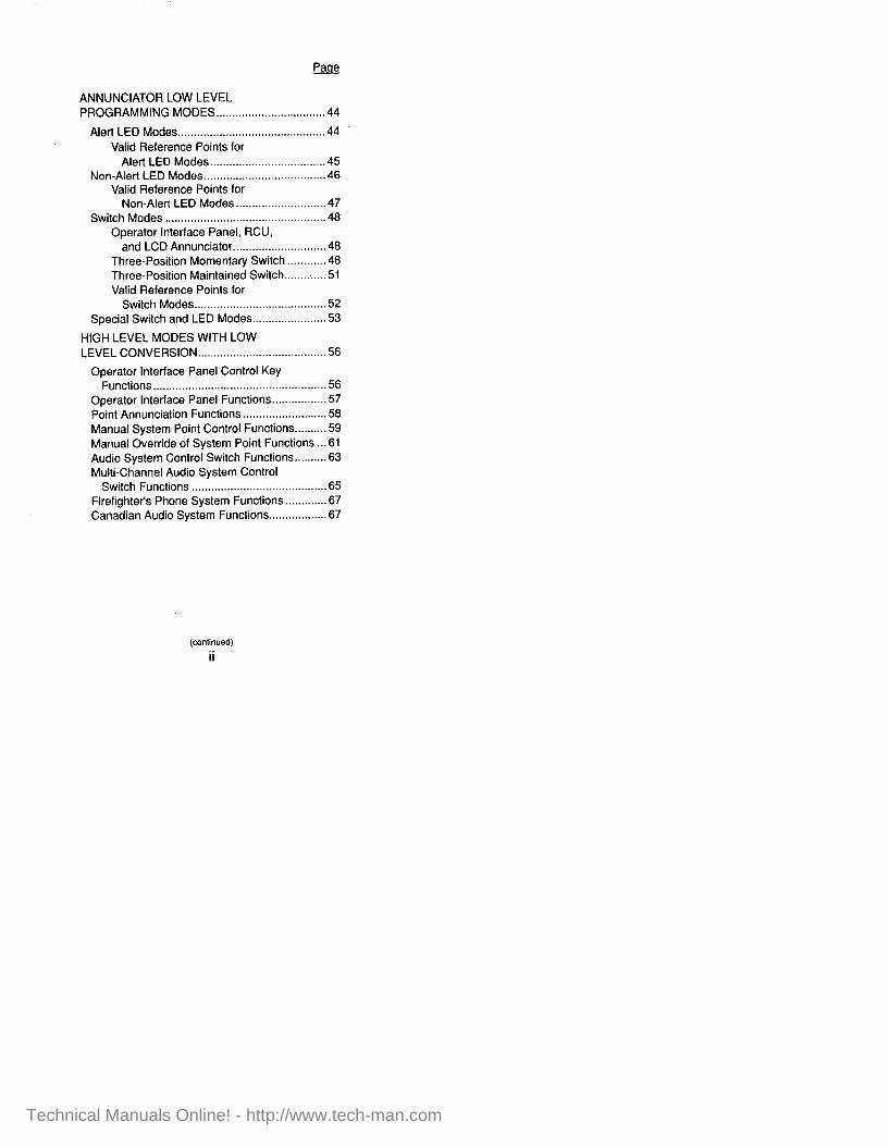
ANNUNCIATOR LOW LEVEL PROGRAMMING MODES .................................. 44
Alert LED Modes .............................................. 44 Valid Reference Points for
Alert LED Modes.. ................................. .45 Non-Alert LED Modes ...................................... 46
Valid Reference Points for Non-Alert LED Modes.. .......................... 47
Switch Modes .................................................. 48 Operator Interface Panel, RCU,
and LCD Annunciator.. .......................... .48 Three-Position Momentary Switch ........... .48 Three-Position Maintained Switch.. ........... .51 Valid Reference Points for
Switch Modes.. ...................................... .52 Special Switch and LED Modes.. .................... .53
HIGH LEVEL MODES WITH LOW LEVEL CONVERSION.. ...................................... 56
Operator Interface Panel Control Key Functions.. ........... ......................................... 56
Operator Interface Panel Functions.. .............. .57 Point Annunciation Functions.. ....................... .58 Manual System Point Control Functions.. ....... .59 Manual Override of System Point Functions .. .61 Audio System Control Switch Functions.. ....... .63 Multi-Channel Audio System Control
Switch Functions ....... ................................... 65 Firefighter’s Phone System Functions.. .......... .67 Canadian Audio System Functions.. ............... .67
ii
Technical Manuals Online! - http://www.tech-man.com

APPENDIX A - CHECKING FOR A BLANK PROM CHIP . . . . . . . . . . . . . . . . . . . . . . . . . . . 69
APPENDIX B - ERASING A PROM CHIP . . . . . 70 APPENDIX C - PROM BURN PROCEDURE
(Version 2.00 and Earlier) . . . . . . 72 APPENDIX D - INSTALLING THE
PROGRAMMING UNIT SOFTWARE ON A HARD DRIVE . . . . . . . . . . . . . . . . . . . . . . . . . . . 75
APPENDIX E - SAVING CHANGES TO AN EXISTING 4100 JOB . . . . . . . . . . . . . 78
APPENDIX F - BACKING UP/ARCHIVING THE 4100 JOB . . . . . . . . . . . . . . . . . . . . . . . . . 79
APPENDIX G - BACKING UP/ARCHIVING THE 4120 NETWORK JOB . . ...80
Technical Manuals Online! - http://www.tech-man.com

Technical Manuals Online! - http://www.tech-man.com

PROGRAMMING UNIT FUNCTION KEYS
The following keys are recognized while entering - data:
[Fl] HELP - activates the first level of the help utility.
[F2] CHOICE LIST - displays choice list for current field if available.
[F3] UNDO - restores field to its original state.
(F4) AUTO-FILL - fills rest of fields with contents of current field. Before Rev. 4.01, you must leave the field to save data and then go back to use autofill mode.
[F5] CLEAR FIELD - fills field with blanks.
[F6) CLEAR END -fills field with blanks from current position of field to the end.
[F7] BEGINNING OF FIELD - moves cursor to start of current field.
[Fe] END OF FIELD - moves cursor to end of current field.
[F9] TAG LIST - activates tag list facility if enabled.
[FlO] EXIT - exit form and save changes without confirmation.
[ALT Fl] - if pressed while in help, zooms help window to full screen.
[HOME] - sends cursor to first field in window.
Technical Manuals Online! - http://www.tech-man.com

[END] - sends cursor to last field in window.
[UP] or [PgUp] - sends cursor tc previous field in window.
[DOWN] or [PgDn] - sends cursor to next field in window.
[LEFT] - cursor left one space at a time.
[RIGHT] - cursor right one space at a time.
[TAB] - sends cursor to next field in window.
[shift-TAB] - sends cursor to previous field in window.
[INS] - toggles insert and typeover modes.
(DEL] - delete character.
[BACKSPACE] -deletes character as it passes over it.
[ENTER] - sends cursor to next field in window.
(ESC] - exits one screen at a time.
Technical Manuals Online! - http://www.tech-man.com
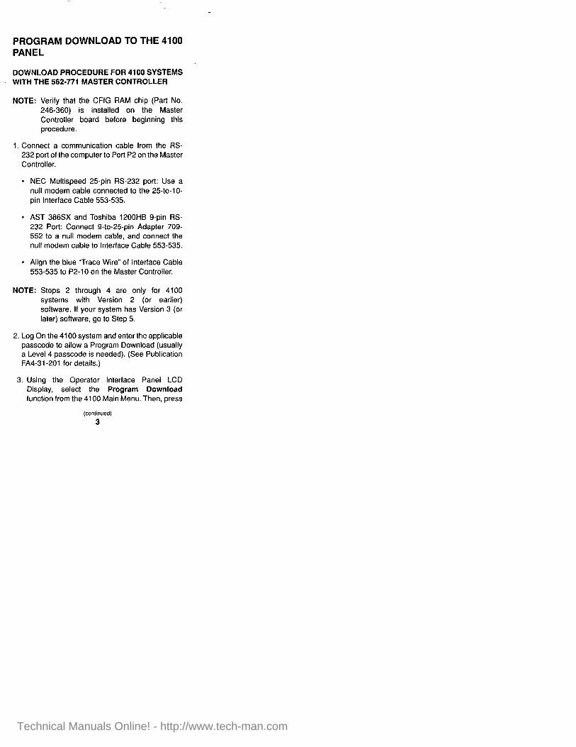
PROGRAM DOWNLOAD TO THE 4100 PANEL
DOWNLOAD PROCEDURE FOR 4100 SYSTEMS WITH THE 562-771 MASTER CONTROLLER
NOTE: Verify that the CFIG RAM chip (Part No. 246-360) is installed on the Master Controller board before beginning this procedure.
1. Connect a communication cable from the RS- 232 port of the computer to Port P2 on the Master Controller.
l NEC Multispeed 25-pin RS-232 port: Use a null modem cable connected to the 25to-lo- pin Interface Cable 553535.
l AST 386SX and Toshiba 1200HB g-pin RS- 232 Port: Connect 9-to-25pin Adapter 709- 552 to a null modem cable, and connect the null modem cable to Interface Cable 553-535.
l Align the blue “Trace Wire” of Interface Cable 553-535 to P2-10 on the Master Controller.
NOTE: Steps 2 through 4 are only for 4100 systems with Version 2 (or earlier) software. If your system has Version 3 (or later) software, go to Step 5.
2. Log On the 4100 system and enter the applicable passcode to allow a Program Download (usually a Level 4 passcode is needed). (See Publication FA4-31-201 for details.)
3. Using the Operator Interface Panel LCD Display, select the Program Download function from the 4100 Main Menu. Then, press
Technical Manuals Online! - http://www.tech-man.com

the <ENTER> key on the Operator Interface Panel Entry Keypad.
4. Press the <Fl> function key above the Operator Interface Panel LCD Display.
5. Configure the Master Controller Write-Enable DIPswitch for a download.
l Remove the write-protect feature from the CFIG RAM chip by sliding switch SWI-1 to the right.
l If the LCD display shows “Waiting for programmer...” you have completed the setup on the 4100 Operator Interface Panel.
6. Using the 4100 Programming Unit, select the Program/Download menu option from the FILE UTILITIES MENU and download the program to the CFIG RAM.
l Select Program Download to 4100 Panel using the cursor arrow keys. Then, press the ENTER key.
l The Programming Unit prompts you to make sure that the 4100 system has been set up to receive the download. Press “Y” if you are ready to continue.
7. The Programming Unit will now download. Notice that the 4100 display shows “Download in progress...”
NOTE: Step 7 is only for 4100 systems with Version 2 (and earlier) software. If your system has Version 3 (or later) software, go to Step 6.
(continued)
4
Technical Manuals Online! - http://www.tech-man.com

8. The Programming Unit will display Download successful. Press any key to continue.
9. To test what was downloaded, you must setup the 4100 to execute from RAM. This is accomplished by setting Master Controller DIPswitch SWl-2 to the left.
lO.Press the CPU Reset Switch S2 on the Master Controller. When the system comes back on-line, a system trouble is generated to warn you that the 4100 is executing from RAM.
NOTE: This mode is for testing purposes only and is not meant to be left in this condition to operate the system.
11 .Test the operation of the downloaded program. If you are satisfied with the operation, burn the CFIG PROM chip and install it in the Master Controller.
12.When you are finished with the download procedure, make sure that you return Master Controller DIPswitches SWl-1 and SWI-2 to their original positions.
PROGRAM DOWNLOAD TO THE 4100+ OR UT CFIG “FLASH” EPROM
Use the following procedure to download programs to the Master Controller CFIG “Flash” EPROM.
1. Connect a Communication Cable from the RS- 232 Port of the PC to Port Pl on the Master Controller.
l NEC Multispeed 25-pin RS-232 Port: Use a null modem cable connected to the 25-to-1 O- pin Interface Cable (Part No. 553-535).
(continued)
5
Technical Manuals Online! - http://www.tech-man.com

l AST 386SX and Toshiba 1200HB g-pin RS- 232 Port: Connect 9.to-25-pin Adapter (Part No. 709-552) to a null modem cable, and connect the null modem cable to the 553-535 Interface Cable.
NOTE: Align the blue “Trace Wire” of the 553-535 Interface Cable to PI -10 on the Master Controller.
2. Configure the Master Controller Write-Enable Jumper P3 for a download by jumpering Pins 1 and 2.
3. Select the Program/Download menu option on the 4100 Programmer and download the program to the CFIG “Flash” EPROM.
4. Move the Master Controller Write-Enable Jumper P3 to the Write-Disable position by jumpering Pins 2 and 3.
PROGRAM DOWNLOAD TO THE 4020 CFIG “FLASH” EPROM
Use the following procedure to download programs to the 4020 Master Controller CFIG “Flash” EPROM.
1. Connect a Communication Cable from the RS- 232 Port of the PC to Port P2 on the 565-209 Master Controller.
l NEC Multispeed 25-pin RS-232 Port: Use a null modem cable connected to the 25-to-IO- pin Interface Cable (Part No. 553-535).
l AST 386SX and Toshiba 1200HB O-pin RS- 232 Port: Connect 9-to-25-pin Adapter (Part No. 709-552) to a null modem cable, and
(continued)
6
Technical Manuals Online! - http://www.tech-man.com

connect the null modem cable to the 553535 Interface Cable.
NOTE: Align the blue “Trace Wire” of the 553-535 Interface Cable to P2-10 on the Master Controller.
2. Configure the Master Controller Write-Enable Jumper P5 (166-l 57 JMP Plug) for a download by jumpering Pins 1 and 2.
3. Select the Program/Download menu option on the 4100 Programmer and download the program to the CFIG “Flash” EPROM.
4. Move the Master Controller Write-Enable Jumper P5 to the Write-Disable position by jumpering Pins 2 and 3.
OTHER 4100 PROGRAMMING PROCEDURES
Building a Job
Use the following procedure to build a job on a 4100 system.
1. Highlight the Job Builder Main Menu item and then press the <Enters key.
2. Select the Job Configuration submenu option and press the <Enter> key.
l Messages will be displayed during the process.
3. After the Job Build related statistics are shown, press any key to continue.
(continued)
7
Technical Manuals Online! - http://www.tech-man.com

Programming (Burning) a CFIG PROM Chip
NOTE: This procedure is for 4100 System Software Version 2.01 and later. To program (burn) PROM chips for Version 2.00 and earlier, see Appendix C.
Use the following procedure to download a 4100 program into the PROMAC PROM programmer and burn a CFIG PROM chip.
1. Highlight the Program/Download Main Menu item and press <Enter>.
2. Select the Job Configuration PROM Burn submenu option and press <Enter>.
3. Select the Download and Burn option and press <Enter>.
4. Select the ROMTYPE from the Menu and press <Enter>.
5. Insert the blank PROM chip into the PROMAC PROM Programmer and press <Enter> on the Programming Unit.
NOTE: To check for a blank PROM chip, see Appendix A.
6. Connect the PROMAC to the RS-232 port on the Programming Unit.
7. Set the PROMAC to “(9600] 8BIT NON SPI” by pressing the PROMAC’s <FUNCTION>, <4>, and &ET> keys and then pressing <Enter> on the Programming Unit.
8
Technical Manuals Online! - http://www.tech-man.com

8. Set the PROMAC for remote control by pressing the PROMAC’s <FUNCTION>, <9r, and <SET; keys and then pressing <Enter* on the Programming Unit.
l The PROMAC beeps twice and starts the download to the PROMAC’s RAM.
l The PROMAC now beeps once. The Programming Unit beeps once, and then the PROMAC beeps once more. The PROM burn is now in progress.
l After a successful PROM burn, the PROMAC and the Programming Unit each beep once. The PROMAC then displays up to 4 digits indicating the checksum.
9. Press the Programming Units <Esca key until you return to the Main Menu.
Technical Manuals Online! - http://www.tech-man.com

DIGITAL PSEUDO POINTS Bold = Trouble Type Mics = Alarm Type
Point PO Pl P2 P3 P4 P5 P6 P7 P8 P9 PlO Pll P12
P13
P14
P15
P16
P17 P18
P19
P20 P21 P22 P23 P24 P25 P26
Custom Label SYSTEM RESET KEY ALARM SILENCE KEY FRONT PANEL LAMPTEST CONTROL ALARM DETECT GLOBAL ACKNOWLEDGE ENABLE SET SERVICE PSEUDO VALUES ALARM SILENCE EXTRA CARD IN THE SYSTEM KEYPAD ACTIVE SYSTEM OUT OF CQB’S CODED INPUT ACTIVE UNACKNOWLEDGED ALARM EXISTS UNACKNOWLEDGED SUPERVISORY EXISTS UNACKNOWLEDGED TROUBLE EXISTS SYSTEM DISABLED - PROGRAMMER DOWNLOAD CFIG RAM WRITE PROTECT MISSING (SWl-1) SMPL PROGRAM 0 - SYSTEM DEFAULT SMPL PROGRAM 1 - AUDIO DEFAULT SMPL PROGRAM 2 - SYSTEM OPTIONS (CODING) SMPL PROGRAM 3 - CUSTOM CONTROL SMPL PROGRAM 4 - USER SMPL SMPL PROGRAM 5 - USER SMPL SMPL PROGRAM 6 - USER SMPL SMPL PROGRAM 7 - USER SMPL CODING GROUP 0 ACTIVE CODING GROUP 1 ACTIVE CODING GROUP 2 ACTIVE
(continued)
10
Technical Manuals Online! - http://www.tech-man.com
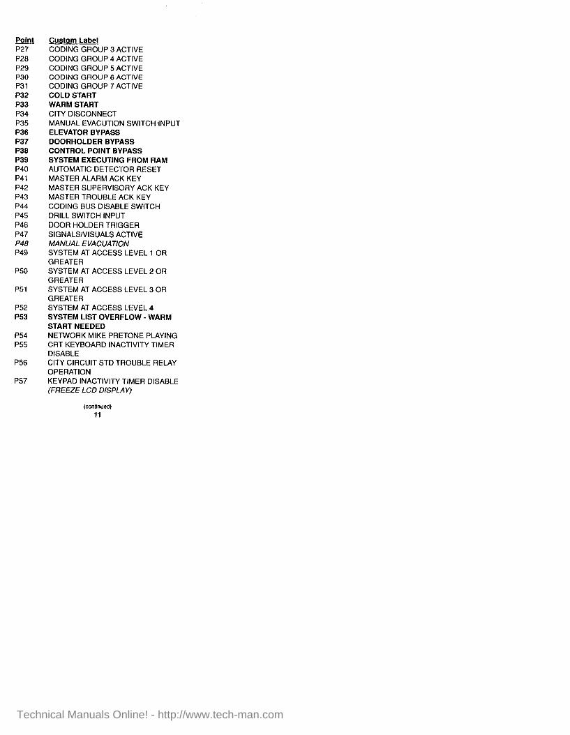
Point Custom Label P27 CODING GROUP 3 ACTIVE P28 P29 P30 P31 P32 P33 P34 P35 P36 P37 P38 P39 P40 P41 P42 P43 P44 P45 P46 P47 P48 P49
P50
P51
P52 P53
P54 P55
P56
P57
CODING GROUP 4 ACTIVE CODING GROUP 5 ACTIVE CODING GROUP 6 ACTIVE CODING GROUP 7 ACTIVE COLD START WARM START CITY DISCONNECT MANUAL EVACUTION SWITCHdNPUT ELEVATOR BYPASS DOORHOLDER BYPASS CONTROL POINT BYPASS SYSTEM EXECUTING FROM RAM AUTOMATIC DETECTOR RESET MASTER ALARM ACK KEY MASTER SUPERVISORY ACK KEY MASTER TROUBLE ACK KEY CODING BUS DISABLE SWITCH DRILL SWITCH INPUT DOOR HOLDER TRIGGER SIGNALS/VISUALS ACTIVE MANUAL EVACUATION SYSTEM AT ACCESS LEVEL 1 OR GREATER SYSTEM AT ACCESS LEVEL 2 OR GREATER SYSTEM AT ACCESS LEVEL 3 OR GREATER SYSTEM AT ACCESS LEVEL 4 SYSTEM LIST OVERFLOW - WARM START NEEDED NETWORK MIKE PRETONE PLAYING CRT KEYBOARD INACTIVITY TIMER DISABLE CITY CIRCUIT STD TROUBLE RELAY OPERATION KEYPAD INACTIVITY TIMER DISABLE (FREEZE LCD DISPLAY)
(continued)
11
Technical Manuals Online! - http://www.tech-man.com

Point P56
P59
P60
P61
P62
P63
P64
P65
P66
P67
P68 P69 P70 P71 P72 P73 P74 P75 P76 P77 P78
P79
P80 P81 P82 P83
Custom Label SYSTEMTlMElDATE INVALID OR NOT SET ALARM VERIFICATION TALLY LIMIT EXCEEDED ALARM VERIFICATION GROUP 0 ACTIVE ALARM VERIFICATION GROUP 1 ACTIVE ALARM VERIFICATION GROUP 2 ACTIVE ALARM VERIFICATION GROUP 3 ACTIVE ALARM VERIFICATION GROUP 4 ACTIVE ALARM VERIFICATION GROUP 5 ACTIVE ALARM VERIFICATION GROUP 6 ACTIVE ALARM VERIFICATION GROUP 7 ACTIVE FIRST STAGE TIMER EXPIRED THE EVAC MESSAGE HAS PLAYED WALK TEST GROUP 0 ENABLED WALK TEST GROUP 1 ENABLED WALK TEST GROUP 2 ENABLED WALK TEST GROUP 3 ENABLED WALK TEST GROUP 4 ENABLED WALK TEST GROUP 5 ENABLED WALK TEST GROUP 6 ENABLED WALK TEST GROUP 7 ENABLED ALARM SILENCE/ALARM CUTOUT PSEUDO RESET SPKRS WHEN AUDIO CODING COMPLETE MASTER MICROPHONE KEYED REMOTE MICROPHONE 1 KEYED REMOTE MICROPHONE 2 KEYED REMOTE MICROPHONE 1 READY TO TALK
(continued)
12
Technical Manuals Online! - http://www.tech-man.com

Point P84
P85 P86 P87 P88 P89 P90 P91 P92 P93 P94 P95 P96 P97 P98 P99 PlOO PlOl Pi02 P103 P104 P105 Pi06 P107 Pi08 P109 PllO Pill P112 Pl13 P114 Pl15 PI16 P117 Pl18 Pi19 P120
Custom Label REMOTE MICROPHONE 2 READY TO TALK VTG 1 - ACTIVE VTG 2 - ACTIVE EVACUATION MESSAGE ON EVACUATION MESSAGE OFF EVACUATION MESSAGE LED ALERT MESSAGE ON ALERT MESSAGE OFF ALERT MESSAGE LED DRILL MESSAGE ON DRILL MESSAGE OFF DRILL MESSAGE LED ALL CLEAR MESSAGE ON ALL CLEAR MESSAGE OFF ALL CLEAR MESSAGE LED AUX MSG 1 ON AUX MSG 1 OFF AUX MSG 1 LED AUX MSG 2 ON AUX MSG 2 OFF AUX MSG 2 LED PHONE PAGING ON PHONE PAGING OFF PHONE PAGING LED AUDIO OVERRIDE ON AUDIO OVERRIDE OFF AUDIO OVERRIDE TROUBLE ALL SPEAKERS MINUS ON ALL SPEAKERS MINUS OFF ALL SPEAKERS MINUS LED ALL SPEAKERS CHANNEL 1 ON ALL SPEAKERS CHANNEL 1 OFF ALL SPEAKERS CHANNEL 1 LED ALL SPEAKERS CHANNEL 2 ON ALL SPEAKERS CHANNEL 2 OFF ALL SPEAKERS CHANNEL 2 LED ALL SPEAKERS CHANNEL 3 ON
Technical Manuals Online! - http://www.tech-man.com

Point P121 Pi22 Pi23 P124 PI25 P126 P127 PI28 P129 P130 P131 P132
PI33
P134
Pi35 P136 P137 P138
PI39
Pi40
P141 P142 PI43 P144
P145
P146 PI47
P149 P149
Custom Label ALL SPEAKERS CHANNEL 3 OFF. ALL SPEAKERS CHANNEL 3 LED LOCAL SPEAKER EVAC ON LOCAL SPEAKER EVAC OFF LOCAL SPEAKER EVAC LED LOCAL SPEAKER ALERT ON LOCAL SPEAKER ALERT OFF LOCAL SPEAKER ALERT LED ALL SPEAKERS TALK ON ALL SPEAKERS TALK OFF ALL SPEAKERS TALK LED ANALOG SENSOR ALMOST DIRTY LOG ENABLE LOG ANALOG SENSOR PEAK VALUE ENABLE CLEAR ANALOG SENSOR PEAK VALUE ALL ALERT ALL EVAC ALL ALERT LED MASTER MIKE PRETONE PLAYING ON VTG 2 REMOTE MIKE 1 PRETONE PLAYING ON VTG 2 REMOTE MIKE 2 PRETONE PLAYING ON VTG 2 MANUAL AUDIO EVAC ON MANUAL AUDIO EVAC OFF MANUAL AUDIO EVAC LED DISABLE SUPERVISION ON VTG 1 (2120 APPL) DISABLE SUPERVISION ON VTG 2 (2120 APPL) EMPTY AUDIO SERVICE QUEUE EVAC MSG PLAYING WHEN MICROPHONE KEYED SYSTEM OUT OF AQB’S SPEAKER SWITCH OFF AUTO
(continued) 14
Technical Manuals Online! - http://www.tech-man.com

&J&t PI50 PI51 Pi52 PI53 P154 Pi55 PI56
Pi57
PI58
PI 59 PI60 P161
PI 62
PI63
PI64
P165 PI66
P167
PI68 PI69 PI70
PI71
P172
P173
PI74
Custom Label AUDIO CODING GROUP 1 ACTIVE AUDIO CODING GROUP 2 ACTIVE VTG 1 - AUDIO SUPERVISION ACTIVE VTG 2 - AUDIO SUPERVISION ACTIVE PHONE TALK LINE RELAY FEEDBACK PHONE NETWORK RELAY FEEDBACK LOCAL MASTER PHONE HANDSET OFF HOOK PHONE TALK LINE RELAY CONTROL INPUT PHONE NETWORK RELAY CONTROL INPUT PHONE TALK LINE RELAY CONTROL PHONE NETWORK RELAY CONTROL MASTER PHONE OFFHOOK SUPERVISION MASTER MIKE PRETONE PLAYING ON VTG 1 REMOTE MIKE 1 PRETONE PLAYING ON VTG 1 REMOTE MIKE 2 PRETONE PLAYING ON VTGI AMPS SWITCHEDTO BATTERY ENABLE RM PHONE TO RM PHONE CONVERSATION ALERT MSG PLAYING WHEN MICROPHONE KEYED MICROPHONETOEVACINEFFECT MICROPHONETOALERTINEFFECT MICROPHONE TO TALK (CHANNEL 3) IN EFFECT BACKGROUND MUSIC RELAY CHANNEL 1 BACKGROUND MUSIC RELAY CHANNEL 2 BACKGROUND MUSIC RELAY CHANNEL 3 VTG 1 CODE’S PRECODE PLAYING
(continued) 15
Technical Manuals Online! - http://www.tech-man.com

Point P175 PI76 P177 PI78 PI79 PI80 PI81 P182 PI83 P184 P185 P186 PI87 P188
PI 89
Pl90 PI91 P192 PI93 Pi94 P195 P196 P197 Pi98 Pl99 P200 P201 P202 P203
P204 P205 P206 P207 P208 P209
Custom Label VTGICODE’SAFTERCODEPLAYING AFTER CODE START - VTG 1 VTG 1 ‘QUIET’MESSAGE PLAYING VTG2CODE’SPRECODEPLAYlNG VTG2CODE’SAFTERCODEPLAYlNG AFTER CODE START - VTG 2 VTG 2’QUIET’MESSAGE PLAYING (2120APPL) VTGl CODE START (2120 APPL) STOP VTGI QUEUE (2120 APPL) VTGP CODE START (2120 APPL) STOP VTG2 QUEUE MIKE DISABLE VTG&LIFIERTROUBLEDlSABLE VTG SUPERVISION TONE NOT ACTIVE SATELLITE PHONE TIMEOUT DISABLE NETWORKMIKEPRETONEPLAYING MASTER MIKE KEYED REMOTE MIKE 1 KEYED REMOTE MIKE 2 KEYED MIKES ARE READY TO PAGE S21 SWITCH ACTIVATED RAM BATTERY MISSING/FAILED 2120 1 COMM LOSS INHIBIT SONALERT INHIBIT ALARM DEFAULT FORCE COLD START AC VOLTAGE FAILURE/BROWNOUT DETECTOR RESET LCD ANNUNCIATORS OVERRIDE KEYSWITCH SIGNALS SILENCED TRUEALARM SENSITIVITY MODIFIED PRINT QUEUE OVERFLOW NETWORK DIAGNOSTIC MODE OUT OFNQB’S COMMUNICATIONS SHORT CIRCUIT TROUBLE
(continued) 16
Technical Manuals Online! - http://www.tech-man.com

po&t Custom Label P210 NETWORK DETECTOR RESET P211 NETWORK SYSTEM RESET P212 DETECTOR/SYSTEM RESET P213 4120 NETWORK CARD CONFIGURED P214 CLEAR VERIFICATION TALLIES P217 NETWORK SIGNAL SILENCE
17
Technical Manuals Online! - http://www.tech-man.com

ANALOG PSEUDO POINTS G A0
Al
A2
A3
A4
A5
A6 A7 A8 A9 Al0 All Al2 Al3 Al4
Al5
Al6
Al7
Al8
Al9
A20
A21
Custom Label Lb!l.e NUMBER OF SYSTEM ALARMS .................................... ANALOG NUMBER OF SYSTEM SUPERVISORIES.. .................... ANALOG NUMBER OF SYSTEM TROUBLES ................................ ANALOG NUMBER OF OLD (UNCLEARED) ALARMS.. ......... ANALOG NUMBER OF OLD (UNCLEARED) SUPERVISORIES.. .................... ANALOG NUMBER OF OLD (UNCLEARED) TROUBLES.. .............................. ANALOG CURRENT HOUR.. .................... ANALOG CURRENT MINUTE.. ................. ANALOG CURRENT SECOND ................. ANALOG CURRENT DAY ......................... ANALOG CURRENT MONTH ................... ANALOG CURRENT YEAR.. ..................... ANALOG CURRENT ACCESS LEVEL .-ANALOG ACCESS LEVEL TIMEOUT.. ..... TIMER SYSTEM RESET WINDOW TIMER.. ...................................... TIMER SYSTEM RESET WINDOW TIMER SETPOINT.. ................... ANALOG DETECTOR RESET PULSE TIMER.. ...................................... TIMER 4-WIRE RESET RELAY PULSE TIMER.. ......................... TIMER ALARM CLEAR DELAY TIMER.. ...................................... TIMER ALARM CLEAR DELAY TIMER SETPOINT.. ................... ANALOG ALARM CLEAR PULSE TIMER.. ...................................... TIMER SYSTEM RESET PULSE TIMER.. ...................................... TIMER
(continued)
18
Technical Manuals Online! - http://www.tech-man.com

Point
A22
A24 A25
A26
A27
A28
A29
A30
A31
A32
A33
A34
A35
A36
A37
A38
A39
A40
Custom Label m!!?
ALARM SILENCE INHIBIT TIMER . . . . . . . . . . . . . . . . . . . . . . . . . . . . . . . . . . . . . . . . TIMER ALARM SILENCE INHIBIT TIMER SETPOINT . . . . . . . . . . . . . . . . . . . . ANALOG ALARM CUTOUT TIMER . . . . . . . . . . . TIMER ALARM CUTOUT TIMER SETPOINT . . . . . . . . . . . . . . . . . . . . . . . . . . . . . . . . . ANALOG ALARM CUTOUT SILENCE PULSE TIMER .,......................... TIMER TROUBLE REMINDER CYCLE TIMER . . . . . . . . . . . . . . . . . . . . . . . . . . . . . . . . . . . . . . . . TIMER TROUBLE REMINDER OFF- TIME SETPOINT . . . . . . . . . . . . . . . . . . . . . . . ANALOG TROUBLE REMINDER ON-TIME SETPOINT . . . . . . . . . . . . . . . . . ANALOG DOOR HOLDER ALARM DROP TIMER . . . . . . . . . . . . . . . . . . . . . . . . . . . . TIMER DOOR HOLDER ALARM DROP TIMER SETPOINT . . . . . . . . ANALOG DOOR HOLDER BROWNOUT DROP TIMER . . . . . . . . . . . . . . . . . . . . . . . . . . . . TIMER DOOR HOLDER BROWNOUT DROP TIMER SETPOINT . . . . . . . . . ANALOG SYSTEM STARTUP PULSE TIMER . . . . . . . . . . . . . . . . . . . . . . . . . . . . . . . . . . . . . . . . TIMER ALARM AUDIBLE SIGNAL OPERATION . . . . . . . . . . . . . . . . . . . . . . . . . . . . . . ANALOG ALARM VISUAL SIGNAL OPERATION . . . . . . . . . . . . . . . . . . . . . . . . . . ANALOG ALARM VERIFICATION - RETARD TIME. . . . . . . . . . . . . . . . . . . . . . . . . . . ANALOG ALARM VERIFICATION - RESET TIME . . . . . . . . . . . . . . . . . . . . . . . . . . . . . ANALOG ALARM VERIFICATION - CONFIRMATION TIME . . . . . . . . . . . . . . ANALOG ALARM VERIFICATION - TALLY LIMIT . . . . . . . . . . . . . . . . . . . . . . . . . . . . . . ANALOG
(continued)
19
Technical Manuals Online! - http://www.tech-man.com

Point A41
A42
A43
A44
A45
A46
A47
A48 A49 A50 A51 A52 A53
A54 A55 A56 A57 A58 A59 A60 A61
A62 A63 A64 A65
A66
Custom Label TEl@S WALK TEST ABORT TIMEOUT SETPOINT.. .............. ANALOG WALK TEST REACTIVATE DELAY SETPOINT .................... ANALOG MONITOR ZONE ENABLE DELAY SETPOINT .................... ANALOG CODED INPUT TIMEOUT SETPOINT ................................. ANALOG OFF TIME AFTER PNIS (NON-CONT.) CODES.. ............. ANALOG CITY CIRCUIT CONFIGURATION ..................... ANALOG ALERT TONEIMSG AFTER MICROPHONE UNKEYED.. ...... ANALOG TOTAL AUDIO CHANNELS.......ANALO G CHANNEL 1 ROUTING ............. ANALOG CHANNEL 2 ROUTING ............. ANALOG CHANNEL 3 ROUTING ............. ANALOG LOCAL ROUTING.. .................... ANALOG EVAC TONE/MSG AFTER MICROPHONE UNKEYED.. ...... ANALOG SUPERVISION MSG# ............... ANALOG EVACUATION MSG# ................. ANALOG ALERT MSG# ............................ ANALOG DRILL MSG#. ............................. ANALOG ALL CLEAR MSG# .................... ANALOG AUX 1 MSG# ............................. ANALOG AUX 2 MSG# ............................. ANALOG MICROPHONE PRETONE MSG#. ........................................ ANALOG PHONE OFFHOOK TIMER.. ..... TIMER PHONE CALLBACK TIMER.. .. ..TIME R PHONE TIMEOUT TIMER.. ....... TIMER REMOTE MASTER PHONE TIMEOUT TIMER.. ..................... TIMER SPEAKER SWITCH OFF AUTO COUNT ........................... ANALOG
(continued)
20
Technical Manuals Online! - http://www.tech-man.com
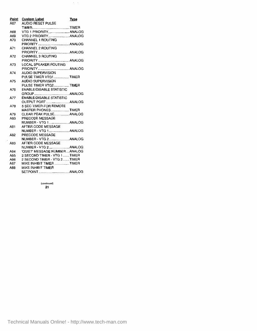
Point A67
A68 A69 A70
A71
A72
A73
A74
A75
A76
A77
A78
A79 A80
A81
A82
A83
A84 A85 A86 A87 A88
Custom Label m AUDIO RESET PULSE TIMER ........................................ TIMER VTG 1 PRIORITY.. ..................... ANALOG VTG 2 PRIORITY.. ..................... ANALOG CHANNEL 1 ROUTING PRIORITY.. ................................ ANALOG CHANNEL 2 ROUTING PRIORITY.. ................................ ANALOG CHANNEL 3 ROUTING PRIORITY.. ................................ ANALOG LOCAL SPEAKER ROUTING PRIORITY.. ................................ ANALOG AUDIO SUPERVISION PULSE TIMER VTGl ................. TIMER AUDIO SUPERVISION PULSE TIMER VTG2.. ............... TIMER ENABLE/DISABLE STATISTIC GROUP.. .................................... ANALOG ENABLE/DISABLE STATISTIC OUTPUT PORT ......................... ANALOG 5 SEC TIMER FOR REMOTE MASTER PHONES.. .................. TIMER CLEAR PEAK PULSE.. .............. ANALOG PRECODE MESSAGE NUMBER - VTG 1 ...................... ANALOG AFTER CODE MESSAGE NUMBER - VTG 1 ...................... ANALOG PRECODE MESSAGE NUMBER - VTG 2.. .................... ANALOG AFTER CODE MESSAGE NUMBER - VTG 2.. .................... ANALOG ‘QUIET MESSAGE NUMBER. ..ANALO G 2 SECOND TlMER - VTG I....... TIMER 2 SECOND TIMER - VTG 2.. ..... TIMER MIKE INHIBIT TIMER ................ TIMER MIKE INHIBIT TIMER SETPOINT.. ............................... ANALOG
(continued) 21
Technical Manuals Online! - http://www.tech-man.com

Point A89
A90
A91
A92
A93
A94
A95
A96
A97
A98
A99
Al00 A101 A102
A103
A104
A105
A106
A107
A108
Custom Label IYIB PHONE CALLBACK TIMER SETPOINT . . . . . . . . . . . . . . . . . . . . . . . . . . . . . . . . . ANALOG PHONE TIMEOUT TIMER SETPOINT .,.,............,................ ANALOG VTG & AMPLIFIER TROUBLE DISABLE TIMER . . . . . . . . . . . . . . . . . . . . . . . . TIMER SUPERVISION NOT ACTIVE - TBL DELAY TIMER . . . . . . . . . . . . . . . . . . . . TIMER 4 WIRE DETECTOR RESET EXTEND TIMER . . . . . . . . . . . . . . . . . . . . . . . . TIMER ACTIVE MESSAGE NUMBER - VTG 1 . . . . . . . . . . . . . . . . . . . . . . . . . . . . . . . . . . . . . . . . . ANALOG ACTIVE MESSAGE NUMBER - VTG 2 . . . . . . . . . . . . . . . . . . . . . . . . . . . . . . . . . . . . . . . . . ANALOG ACTUAL CHIPSET PLUGGED INTO VTG 1 ,.............,,............... ANALOG ACTUAL CHIPSET PLUGGED INTO VTG 2 ,....,......................... ANALOG BATTERY TROUBLE COUNTER . . .._............................... COUNTER AC POWER FAIL COUNTER . . . . . . . . . . . . . . . .._.................. COUNTER SYSTEM TYPE .,,.............,...,..... ANALOG FIRST STAGE TIMER . . . . . . . . . . . . . . . ANALOG FIRST STAGE TIMER SETPOINT . . . . . . . . . . . . . . . . . . . . . . . . . . . . . . . . . ANALOG MASTER MIKE 5 SECOND UNKEY DELAY . . . . . . . . . . . . . . . . . . . . . . . . . . ANALOG REMOTE MIKE 1 5 SECOND UNKEY DELAY ,......................... ANALOG REMOTE MIKE 2 5 SECOND UNKEY DELAY . . . . . . . . . . . . . . . . . . . . . . . . . . ANALOG MASTER MIKE’S PRETONE TIMER . . . . . . . . . . . . . . . . . . . . . . . . . . . . . . . . . . . . . . . . ANALOG MASTER MIKE’S PRETONE SETPOINT . . . . . . . . . . . . . . . . . . . . . . . . . . . . . . . . . ANALOG REMOTE MIKE 1’S PRETONE TIMER .,,......,.......,........,,....,..,,... ANALOG
(continued) 22
Technical Manuals Online! - http://www.tech-man.com

Point A109
A110
All1
All2
All3 A114
All5
All6 All7 All8
A119
A120 A121
Custom Label TYfE REMOTE MIKE 1’S PRETONE SETPOINT.. ............................... ANALOG REMOTE MIKE 2’S PRETONE TIMER.. ...................................... ANALOG REMOTE MIKE 2’S PRETONE SETPOINT.. ............................... ANALOG GROUND TROUBLE COUNTER .................................... COUNTER PAGING CHANNEL.. ................. ANALOG TRUEALARM MODIFICATION COUNTER .................................... COUNTER EXCESSIVELY DIRTY (OUT OF RANGE) ..................... ANALOG DIRTY SENSOR COUNTER ...... COUNTER ALMOST DIRTY COUNTER ...... COUNTER ALARMS SILENCED DELAY TIMER.. ...................................... TIMER NUMBER OF LOCAL SYSTEM POINTS’ TROUBLES.. ................ COUNTER SYSTEM PAGING STATUS.......ANALO G KEYPAD INACTIVITY TIMEOUT SETPOINT.. .............. ANALOG
23
Technical Manuals Online! - http://www.tech-man.com

POINT LIST SUMMARY &t LO
Ll L2 L3 L4 L5 L6 L7 L8 L9 LlO Lil L12 L13 L14 Ll5
L16
L17 L18 L19
L20
L21
L22
L23
L24
L25
Descrbtlon CODING GROUP 0 SIGNALS/RELAYS (NON-PNIS) CODING GROUP 1 SIGNALS/RELAYS CODING GROUP 2 SIGNALS/RELAYS CODING GROUP 3 SIGNALS/RELAYS CODING GROUP 4 SIGNALS/RELAYS CODING GROUP 5 SIGNALS/RELAYS CODING GROUP 6 SIGNALS/RELAYS CODING GROUP 7 SIGNALS/RELAYS ALARM SIGNALS OFF ON SILENCE ALARM SIGNALS OFF ON RESET ALARM RELAYS OFF ON SILENCE ALARM RELAYS OFF ON RESET ALARM VISUALS OFF ON SILENCE ALARM VISUALS OFF ON RESET TROUBLE RELAYS OFF ON CLEAR TROUBLE RELAYS OFF ON ACKNOWLEDGE RELAYS PULSED ON SYSTEM (DETECTOR) RESET DOOR HOLDER CONTROL RELAYS GENERAL ALARM MONITOR ZONES PRIMARY ELEVATOR RECALL MONITOR ZONES ALTERNATE ELEVATOR RECALL MONITOR ZONES PRIMARY ELEVATOR CAPTURE RELAYS ALTERNATE ELEVATOR CAPTURE RELAYS WATERFLOW ALARM MONITOR ZONES WATERFLOW SIGNALS OFF ON SILENCE WATERFLOW SIGNALS OFF ON RESET
(continued) 24
Technical Manuals Online! - http://www.tech-man.com

&t L26
L27
L28 L-29
L30 L31 L32 L33 L34 L35 L36 L37 L38 L39 L40 L4l L42 L43 L44 L45 L46 L47 L48 L49 L50
L51
L52
L53
L54
L55
DescritNon SPRINKLER SUPERVISORY MONITOR ZONES SPRINKLER SUPERVISORY SIGNALS/ RELAYS USER SYSTEM LISTS EDITABLE GENERAL ALARM SYSTEM LISTS ALARM VERIFICATION GROUP 0 ALARM VERIFICATION GROUP i ALARM VERIFICATION GROUP 2 ALARM VERIFICATION GROUP 3 ALARM VERIFICATION GROUP 4 ALARM VERIFICATION GROUP 5 ALARM VERIFICATION GROUP 6 ALARM VERIFICATION GROUP 7 4 WIRE MONITOR ZONES NOT USED WALK TEST GROUP 0 WALK TEST GROUP 1 WALK TEST GROUP 2 WALK TEST GROUP 3 WALK TEST GROUP 4 WALK TEST GROUP 5 WALK TEST GROUP 6 WALK TEST GROUP 7 NOT USED NOT USED WALK TEST GROUP 0 - SIGNALS/ RELAYS WALK TEST GROUP 1 - SIGNALS/ RELAYS WALK TEST GROUP 2 - SIGNALS/ RELAYS WALK TEST GROUP 3 - SIGNALS/ RELAYS WALK TEST GROUP 4 - SIGNALS/ RELAYS WALK TEST GROUP 5 - SIGNALS/ RELAYS
(continued)
25
Technical Manuals Online! - http://www.tech-man.com
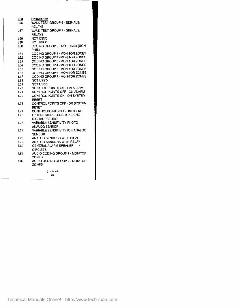
List L56
L57
L58 L59 L60
L61 L62 163 L64 L65 L66 L67 L68 L69 L70 L71 L72
L73
L74 L75
L76
L77
L78 179 L80
L81
L82
Description WALK TEST GROUP 6 - SIGNALS/ RELAYS WALK TEST GROUP 7 - SIGNALS/ RELAYS NOT USED NOT USED CODING GROUP 0 - NOT USED (NON- PNIS) CODING GROUP 1 - MONITOR ZONES CODING GROUP 2 - MONITOR ZONES CODING GROUP 3 - MONITOR ZONES CODING GROUP 4 - MONITOR ZONES CODING GROUP 5 - MONITOR ZONES CODING GROUP 6 - MONITOR ZONES CODING GROUP 7 -MONITOR ZONES NOT USED NOT USED CONTROL POINTS ON - ON ALARM CONTROL POINTS OFF - ON ALARM CONTROL POINTS ON - ON SYSTEM RESET CONTROL POINTS OFF - ON SYSTEM RESET CONTROLPOINTSOFF-ONSILENCE LPHONE MODE LEDS TRACKING DIGITAL PSEUDO VARIABLE SENSITIVITY PHOTO ANALOG SENSOR VARIABLE SENSITIVITY ION ANALOG SENSOR ANALOG SENSORS WITH PIEZO ANALOG SENSORS WITH RELAY GENERAL ALARM SPEAKER CIRCUITS AUDIO CODING GROUP 1 - MONITOR ZONES AUDIO CODING GROUP 2 - MONITOR ZONES
(conlinued)
26
Technical Manuals Online! - http://www.tech-man.com

&t L83 L84 L85
L86
L87 L88 L89
L90 L91
L92
L93 L94 L95
L96
L97
L98
L99
LlOO
LlOl L102
L103
LlO4 L105
Description AUXl MESSAGE SPEAKERS AUX2 MESSAGE SPEAKERS RESTART MESSAGE AFTER MIKE - VTG 1 RESTART MESSAGE AFTER MIKE - VTG 2 AHU RELAYS ON - ON ALARM AHU RELAYS OFF - ON ALARM AHU RELAYS OFF - ON SYSTEM RESET ALL SPEAKERS - NON EDITABLE AUDIO CODING GROUP 1 - SIGNAL CIRCUITS AUDIO CODING GROUP 2 - SIGNAL CIRCUITS PHONE CIRCUITS REMOTE MASTER PHONE CIRCUITS SATELLITE PHONES - SCC 4100 ON/ OFF SATELLITE PHONES - SCC 4100 NORMAL/SHORT SATELLITE PHONES - SCC 4100 ON/ OFF RMPH SWITCH POWER SUPPLY AMPS TO BATTERY SWITCH POWER SUPPLY AMPS TO BKGRND MUSIC POINTS TO EXCLUDE FROM AUTOMAP RESET POWER SUPPLY AMPS LISTS TO AUTO-GENERATE EXTERNAL POINTS EXTERNALDETECTORRESET POINTS EXTERNAL CONTROL RESET POINTS EXTERNAL ENTIRE SYSTEM RESET POINTS
27
Technical Manuals Online! - http://www.tech-man.com

!& Description L106 EXTERNAL ALARM SILENCE POINTS L107 ENTER LOCAL MODE ON DATA NOT
AVAILABLE L108 EXTERNAL SPEAKERS AND
SPEAKER LISTS 1109 ALARM SILENCED LED CONTROL
28
Technical Manuals Online! - http://www.tech-man.com

POINT LIST GENERATION The following point lists are auto-filled using listed point types and are for General Alarm Operation. Edit these point lists from the Non-General Alarm option of the Expanded Operation menu.
Point Custom Point Label LO CODING GROUP 0 SIGNALS/RELAYS (NON-
PNIS): ss. rs. sv. N L8 L9 LiO Lll LIZ L13 L16
L17 L18
L19
L21 L22 L61
L78
L79
ALAdM S’lGNAiS OFF ON SILENCE: ss ALARM SIGNALS OFF ON RESET: rs ALARM RELAYS OFF ON SILENCE: sr ALARM RELAYS OFF ON RESET: rr ALARM VISUALS OFF ON SILENCE: sv ALARM VISUALS OFF ON RESET: N RELAYS PULSED ON SYSTEM (DETECTOR) RESET: dr DOOR HOLDER CONTROL RELAYS: dh GENERAL ALARM MONITOR ZONES: all alarm point types PRIMARY ELEVATOR RECALL ZONES: alarm point types’ PRIMARY ELEVATOR CAPTURE RELAYS: pri ALTERNATE ELEVATOR CAPTURE RELAYS: all CODING GROUP I- MONITOR ZONES: zones w/ PNIS code ANALOG SENSORS WITH PIEZO: pph, vph*; sph, sio, she, soh3 ANALOG SENSORS WITH RELAY: rph”; pho, sph, rph3
LEO L87 L88 L89
L108
GENERAL ALARM SPEAKER CIRCUITS: sp4 AHU RELAYS ON - ON ALARM: ahuo. ahur; cda5 AHU RELAYS OFF _ ON ALARM: ahuf5 AHU RELAYS OFF _ ON SYSTEM RESET: ahuo. ahur, ahuf, cda5 EXTERNAL SPEAKERS AND SPEAKER LISTS: network external sp
NOTES: 1. Initialized lo L18 until Alternate Recall is set up. 2. Version 3 of the Programming Unit software. 3. Version 4 of the Programming Unit software. 4. This point list is cleared if the current job has coded zones. 5. Version 3: L87 replaced L70. L88 replaced L71, L89 replaced L73:
effective in Version 3, L70 through L74 are manually filled in by Ihe operator.
29
Technical Manuals Online! - http://www.tech-man.com

The following point lists are automatically filled according to listed point types and are for Waterflow-Sprinkler Supervisory operation. These lists are not editable.
m Custom Point Label L23 WATERFLOW ZONES: w, wso, wsc L26 SPRINKLER SUPERVISORY ZONES: so,
SC, wso, wsc
The following point lists are used in conjunction with Point Lists L23 and L26 respectively, and are automatically filled and edited from that option in the Standard Operations submenu.
Point Custom Point Label L24 WATERFLOW SIGNALS OFF ON
SILENCE: SW L25 WATERFLOW SIGNALS OFF ON RESET
rw L27 SPRINKLER SUPERVISORY SIGNALS/
RELAYS: su
The following point lists are automatically filled and are editable from their associated option in the Operations Menu.
Poi_nt Custom Point Label L30 ALARM VERIFICATION GROUP 0: alarm
point types* L40 WALKTEST GROUP 0 ZONES: all monitor
zones L50 WALKTEST GROUP 0 SIGS/RELAYS: ss,
rs, sv, rv, sp, coded
l Initialized to L18 until multiple groups are set up.
30
Technical Manuals Online! - http://www.tech-man.com
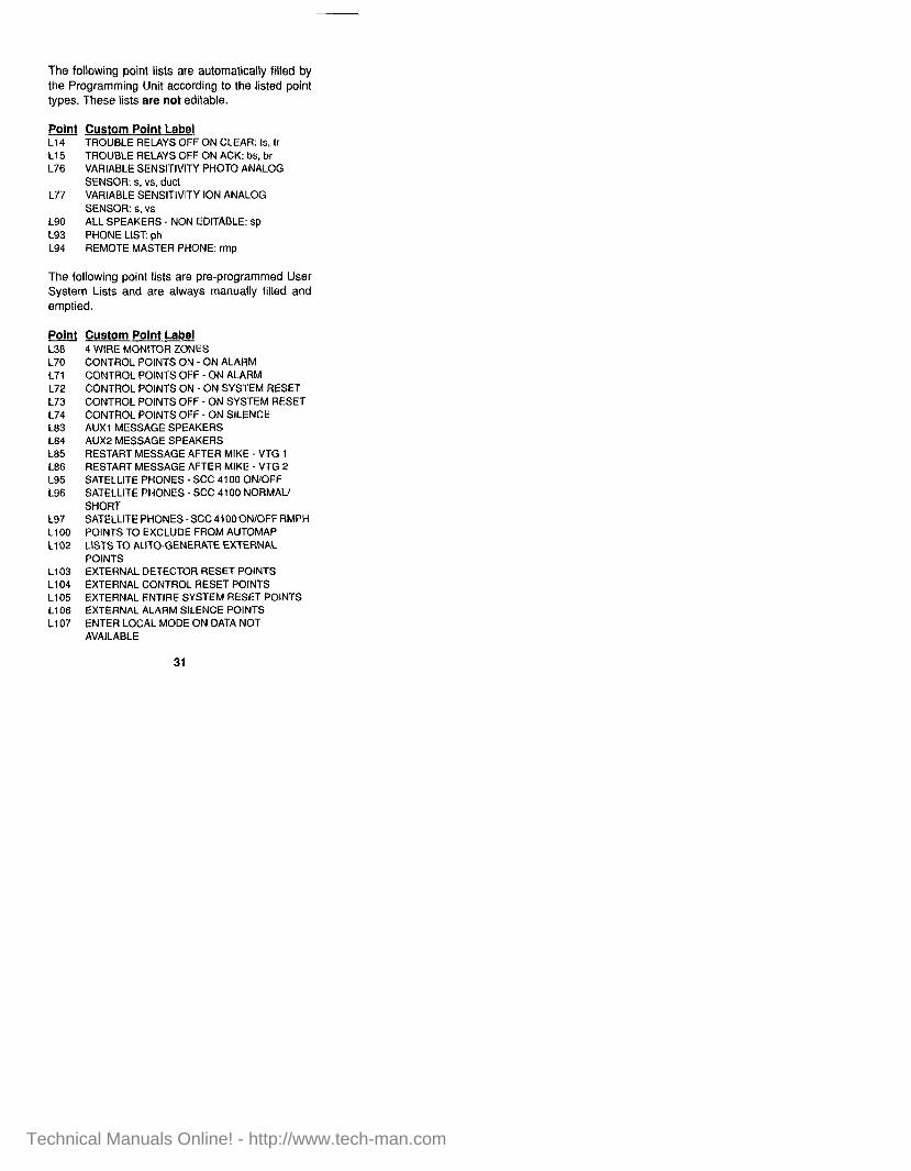
The following point lists are automatically filled by the Programming Unit according to the listed point types. These lists are not editable.
&dnJ Custom Point Label L14 TROUBLE RELAYS OFF ON CLEAR: ts, lr
.L15 TROUBLE RELAYS OFF ON ACK: bs. br L76 VARIABLE SENSITIVITY PHOTO ANALOG
SENSOR: s, vs, duct 177 VARIABLE SENSITIVITY ION ANALOG
SENSOR: s, vs LQO ALL SPEAKERS _ NON EDITABLE: sp L93 PHONE LIST: ph L94 REMOTE MASTER PHONE: rmp
The following point lists are pre-programmed User System Lists and are always manually filled and emptied.
Point Custom Point Label L38 L70 L71 L72 L73 L74 L83 L84 L85 L86 L95 L96
L97 LlOO L102
L103 L104 L105 L106 L107
4 WIRE MONITOR ZONES CONTROL POINTS ON - ON ALARM CONTROL POtNTS OFF - ON ALARM CONTROL POINTS ON - ON SYSTEM RESET CONTROL POINTS OFF - ON SYSTEM RESET CONTROL POINTS OFF - ON SILENCE AUXl MESSAGE SPEAKERS AUX2 MESSAGE SPEAKERS RESTART MESSAGE AFTER MIKE - VTG 1 RESTART MESSAGE AFTER MIKE - VTG 2 SATELLITE PHONES . SCC 4100 ON/OFF SATELLITE PHONES - SCC 4100 NORMAU SHORT SATELLITEPHONES-SCC4100ONlOFFRMPH POINTS TO EXCLUDE FROM AUTOMAP LISTS TO AUTO-GENERATE EXTERNAL POINTS EXTERNAL DETECTOR RESET POINTS EXTERNAL CONTROL RESET POINTS EXTERNAL ENTIRE SYSTEM RESET POINTS EXTERNAL ALARM SILENCE POINTS ENTER LOCAL MODE ON DATA NOT AVAILABLE
31
Technical Manuals Online! - http://www.tech-man.com

32
POINT TYPES
MONITOR POINTS
Bold = Default
Name Description ALARM ............ Generic Fire Alarm Point WATER ............ Waterflaw Switch HEAT ................ Heat Detector DUCT ............... Duct Detector FLAME.. ........... Flame Detector PULL.. .............. Manual Pull Station SMOKE.. .......... Smoke Detector VSMOKE.. ........ Verified Smoke Detector CODEDIN ........ Coded Input EMERG.. .......... Combo Fire (SHORT) and
Emergency (CURRENT-LIMITED) SFIRE .............. Smoke/Fire Combination Zone VSFIRE ............ Verified Smoke/Fire Combination
Zone SPULL.. ............ Smoke/Pull Combination Zone VSPULL ........... Verified Smoke/Pull Combination
Zone GENMON ......... Emergency Generator Monitor SGENMON ...... Supervisory Emergency Generator
Monitor FPUMP ............ Fire Pump Monitor SFPUMP .......... Supervisory Fire Pump Monitor ABORT.. ........... Abort Zone (Pre-Signal) S2STAGE ......... Two-Stage Monitor (Stage 1
CURRENT-LIMITED; Stage 2 SHORT)
SO.. .................. Sprinkler (Tamper) Supervisory (N.O. Contacts)
SC .................... Sprinkler (Tamper) Supervisory (NC. Contacts)
Technical Manuals Online! - http://www.tech-man.com

MONITOR POINTS (Cont.)
Nems Descrbtion WSO . . . . . . . . . . . . . . . . Combo Waterflow/Sprinkler
(Tamper) Supervisory (N.O. Contacts)
WSC . . . . . . . . . . . . . . . Combo Waterflow/Sprinkler (Tamper) Supervisory (N.C. Contacts)
SUPDET . . . . . . . . . . Suppression Agent Monitor Zone SUPABRT . . . . . . . Suppression Agent Abort Zone SUPDUMP. . . . . . . Suppression Agent Manual Dump SUPPRES........Suppression Agent Pressure
Monitor SUPERV . . . . . . . . Generic Supervisory Point UTILITY . . . . . . . . . . . . Non-Alarm w/Tri-State Ability TROUBLE . . . . . . . . Trouble Monitor DAMPER . . . . . . . . . . Damper Monitor (Open/Closed) TDAMPER . . . . . Tri-State Damper (CtrlOpenl
Closed)
SIGNAL POINTS
Bold = Default
Name Descrbtion SIGNAL . . . . . . . . . . Generic Signal RELAY . . . . . . . . . . . . . Supervised Control Relay SSIGNAL . . . . . . . . . Alarm Signal (On until Alarm
Silence) RSIGNAL . . . . . . . . . Alarm Signal (On until System
Reset) TSIGNAL . . . . . . . . . . TrbVSuperv Signal (On until
Cleared) BSIGNAL . . . . . . . . . TrbVSuperv. Signal (On until
ACKed) SPEAKER ..,,.... Alarm Speaker Circuit PHONE . . . . . . . . . . . . Fire Phone Circuit RMPHONE....... Remote Master Fire Phone Circuit
Technical Manuals Online! - http://www.tech-man.com

SIGNAL POINTS (Cont.)
Name Descrbtion CODED . . . . . . . . . . . . Coded Signal (PNIS or Coded
Input) SVISUAL.......... Visual Alarm Signal (On until Alarm
Silence) RVISUAL . . . . . . . . . . Visual Alarm Signal (On until
System Reset) SWATER . . . . . . . . . . Waterflow Signal (On until Alarm
Silence) RWATER . . . . . . . . . . Waterflow Signal (On until System
Reset) SUPERV . . . . . . . . . . Sprinkler Supervisory Signal SUPRELS . . . . . . . . Suppression Release Control
Relay
AUX. RELAY POINTS
Bold = Default
Name Descrbtion RELAY . . . . . . . . . . . . . General Purpose Relay PRIMARY . . . . . . . . . Primary Elevator Recall: Alarm
Relay ALTERN . . . . . . . . . . . Alternate Elevator Recall AHUR ..,............ Air Handling Unit (AHU) Alarm
Relay - On/Off AHUO . . . . . . . . . . . . . . . AHU Afarm Relay - On AHUF . . . . . . . . . . . . . . . AHU Alarm Relay - Off CODED . . . . . . . . . . . . Coded Relay (PNIS or Coded
Input) CPRESS .,........ Pressurization Fan/Damper, Relay
(On/Off) CEXHAUS . . . . . . . . Exhaust, Fan/Damper, Relay (On/
OffI CDAMPER . . . . . . . Damper Control (On/Off), Alarm
Relay
(continued)
34
Technical Manuals Online! - http://www.tech-man.com

AUX. RELAY POINTS (Cont.)
Name Descrbtion SRELAY.. ......... Alarm Relay (On until Alarm
Silence) RRELAY.. ......... Alarm Relay (On until System
Reset) TRELAY ........... Trbl/Superv. Relay (On until
Cleared) BRELAY.. ......... TrbVSuperv. Relay (On until
ACKed) DRESET .......... Detector Reset Relay (4-Wire) DHOLDER ....... Door Holder Control Alarm Relay SWATER .......... Waterflow Relay (On until Alarm
Silence) RWATER.. ........ Waterflow Relay (On until System
Reset) SUPERV .......... Sprinkler Supervisory Relay SVISUAL.. ........ Visual Alarm Relay (On until Alarm
Silence) RVISUAL.. ........ Visual Alarm Relay (On until
System Reset) SSIGNAL ....... ..Alar m Signal Relay (On until Alarm
Silence) RSIGNAL ......... Alarm Signal Relay (On until
System Reset)
35
Technical Manuals Online! - http://www.tech-man.com

FEEDBACK POINTS
Bold = Default
Name Description DAMPER . . . . . . . . . . Damper Monitor (Open/Closed) AHUMON . . . . . . . . . AHU Monitor (On/Off) PRESSUR........ Pressurization Monitor (On/Off) EXHAUST . . . . . . . . Exhaust Monitor (On/Off) ONOFF ..,......... Utility Monitor (On/Off), N.O.
Contact
GRAPHIC I/O POINTS
Bold = Default
Name Description UTILITY ............ Non-Alarm Utility Monitor TROUBLE.. ...... Generic Trouble Monitor USWITCH Two-Position Input - ........
Unsupervised OSWITCH.. ...... Two-Position Input - Open
Supervisory SSWITCH ........ Two-Position Input - Open/Short
supv. TSWITCH.........Three-Positio n HOA Input-Open
supv. DAMPER .......... Damper Monitor (Open/Closed) TDAMPER ....... Tri-State Damper (Ctr/Open/
Closed) AHUMON ......... AHU Monitor (On/Off) PRESSUR ........ Pressurization Monitor (On/Off) EXHAUST.. ...... Exhaust Monitor (On/Off) ONOFF ............ Utility Monitor (On/Off), N.O.
Contact OFFON ............ Utility Monitor (On/Off), NC.
Contact EP .................... AHU Monitor - Exhaust/Pressure/
Norm LAMP ............... Lamp Output (w/Lamp Test) PIEZO .............. Pie20 Output
(continued)
36
Technical Manuals Online! - http://www.tech-man.com

GRAPHIC l/O POINTS (Cont.)
Name Descrbtion SUPRELS ........ Suppression Release Output RELAY ............. Generic Remote Relay (On/Off) PRIMARY.. ....... Primary Elevator Recall, Gen.
Alarm ALTERN.. ......... Alternate Elevator Recall AHUR ............... Remote AHU Alarm Relay -On/Off
(Single) AHUO.. ............. Remote AHU Alarm Relay - On
(Dual) AHUF ............... Remote AHU Alarm Relay - Off
(Dual) CPRESS .......... Pressure Control (On/Off) CEXHAUS ........ Exhaust Control (On/Off) CDAMPER ....... Damper Control (On/Off), Gen.
Alarm SRELAY ........... Alarm Relay (On until Alarm
Silence) RRELAY.. ......... Alarm Relay (On until System
Reset) TRELAY.. ......... Trbl/Superv. Relay (On until
Cleared) BRELAY ........... Trbl/Superv. Relay (On until
ACKed)
DIGITAL PSEUDO POINTS
Bold = Default
Name Description UTILITY . . . . . . . . . . . Non-Alarm Utility Point
- ALARM.. ........... Alarm Point SUPERV .......... Supervisory Point TROUBLE.. ...... Trouble Point
37
Technical Manuals Online! - http://www.tech-man.com

ANALOG PSEUDO POINTS
Bold = Default
Name Descrbtion ANALOG .,....... Stores Analog Value TIMER . . . . . . . . . . . . . . Used for timing functions COUNTER . . . . . . . Used for counting functions
38
Technical Manuals Online! - http://www.tech-man.com

MAPNET II@ ADDRESSABLE DEVICE POINT TYPES
NOTES: 1. Bold type indicates default point type,
2. Version 3 of the Programming Unit uses a “v” designation on the device type to indicate variable device sensitivity. Version 3 of the Programming Unit converts earlier device types to the current device type. For Version 4 (and later), the “V” designator was dropped because all sensors became variable sensitivity sensors.
MONITOR DEVICE TYPES
Device Point Tvpe ADRDET SMOKE, HEAT, DUCT,
VSMOKE, SUPDET Addressable Detector Base MBZAM ALARM, WATER, HEAT, DUCT,
FLAME, PULL, SMOKE, VSMOKE, ABORT, SO, SUPDET, SUPERV, UTILITY, TROUBLE, DAMPER
One-Zone Style B Monitor ZAM MAZAM ALARM, WATER, HEAT, DUCT,
FLAME, PULL, SMOKE, VSMOKE, ABORT, SO, SUPDET, SUPERV, UTILITY,
, TROUBLE, DAMPER One-Zone Style D Monitor ZAM ADRPUL PULL Addressable Pull Station 4WZAM SMOKE, ALARM, DUCT,
VSMOKE Four- Wire Defector ZA M PSMON TROUBLE Power Supply Monitor
Technical Manuals Online! - http://www.tech-man.com

MONITOR DEVICE TYPES (Cont.)
GENIAM UTILITY, ALARM, WATER, HEAT, DUCT, FLAME, PULL, SMOKE, VSMOKE, ABORT, SO, SUPDET, SUPER’/, TROUBLE, DAMPER
Single Device Monitor ZAM
ANALOG DETECTOR DEVICE TYPES
NOTE: The following are TrueAlarmTM devices.
Device Point Tvpe PHOTO SMOKE, VSMOKE, DUCT Photoelectric Sensor TPHOTO SMOKE, VSMOKE, DUCT Single Station Photoelectric Sensor SPHOTO SMOKE, VSMOKE, DUCT Photoelechic Sensor w/Sounder Base RPHOTO SMOKE, VSMOKE, DUCT Photoelectric Sensor w/Relay Base CPHOTO SMOKE, VSMOKE Caged Phofoelectric Sensor CTPHOTO SMOKE, VSMOKE Caged Sing/e Station Photoelectric Sensor CSPHOTO SMOKE, VSMOKE Caged PhotoelecWic Sensor w/Sounder Base CRPHOTO SMOKE, VSMOKE Caged Photoelectric Sensor w/Relay Base XPHOTO SMOKE, VSMOKE, DUCT Extra-Sensifive PhoIoelectric Sensor ? XSPHOTO SMOKE, VSMOKE, DUCT Extra-Sensitive Photoelectric Sensor w/Sounder Base XRPHOTO SMOKE, VSMOKE, DUCT Extra-Sensitive Photoelectric Sensor w/Relay Base XTPHOTO SMOKE, VSMOKE Extra-Sensitive Single Station Photoelectric Sensor ION SMOKE, VSMOKE Ionization Sensor
(continued)
40
Technical Manuals Online! - http://www.tech-man.com

ANALOG DETECTOR DEVICE TYPES (Cont.)
Point Tvpe SMOKE. VSMOKE
Single Station Ionization Shsor SION SMOKE, VSMOKE Ionization Sensor w/Sounder Base RION SMOKE, VSMOKE Ionization Se. ‘sor w/Relay Base UHEAT UTILITY Heat Sensor (Non-Alarm) HEAT HEAT, UTILITY Heat Sensor (Fixed) SHEAT HEAT, UTILITY Heat Sensor (Fixed) w/Sounder Base RHEAT HEAT, UTILITY Heat Sensor (Fixed) w/Relay Base OHEAT HEAT, UTILITY Heat Sensor (Fixed) w/ROR (Rate-of-Rise) SOHEAT HEAT, UTILITY Heat Sensor (Fixed) w/ROR and w/Sounder Base ROHEAT HEAT, UTILITY Heat Sensor (Fixed) w/ROR and w/Relay Base
CONTROL DEVICE TYPES
Device SBZAM
Point Tvpe SSIGNAL. RSIGNAL. TSIGNAL. BSIGNAL; SVISUAL;RVISUAL; SWATER, RWATER, SUPERV,
i; RELAY, SUPRELS, SPEAKER, PHONE, SIGNAL, PRIMARY, ALTERN, AHUR, AHUO, AHUF, CPRESS, CEXHAUS, CDAMPER, DRESET, DHOLDER
Style Y Signal ZAM
(continued)
41
Technical Manuals Online! - http://www.tech-man.com

CONTROL DEVICE TYPES (Cont.)
Device Point TVDe SAZAM SSIGNAL, RSIGNAL, TSIGNAL,
BSIGNAL, SVISUAL, RVISUAL, SWATER, RWATER, SUPERV, RELAY, SUPRELS, SPEAKER, PHONE, SIGNAL, PRIMARY, ALTERN, AHUR, AHUO, AHUF, CPRESS, CEXHAUS, CDAMPER, DRESET, DHOLDER
Style Z Signal ZAM RZAM RRELAY, RELAY, PRIMARY,
ALTERN, AHUR, AHUO, AHUF, CPRESS, CDAMPER, SRELAY, TRELAY, BRELAY, DRESET, DHOLDER, SVISUAL, RVISUAL, CEXHAUS, RWATER, SWATER, SUPER’4 SSIGNAL, RSIGNAL
Control ZAM
ISOLATOR DEVICE TYPES
Device Point Tvpe IS0 IS0 MAPNET II@ Isolator Card Loor,
MISCELLANEOUS DEVICE TYPES
Device Point Tvpe NULMON SMOKE, ALARM, WATER,
HEAT, DUCT, FLAME, PULL, VSMOKE, ABORT, SO, SUPDET, SUPERV, UTILITY, TROUBLE, DAMPER
Null MAPNET It@ Monitor Device
(continued)
42
Technical Manuals Online! - http://www.tech-man.com

MISC. DEVICE TYPES (Cont.)
Device Point Tvpe NULSIG SSIGNAL. RSIGNAL.TSIGNAL.
BSIGNAL:SVISUAL,‘RVISUAL: SWATER, RWATER, SUPERV, RELAY, SUPRELS, SPEAKER, PHONE, SIGNAL, PRIMARY, ALTERN, AHUR, AHUO, AHUF, CPRESS, CEXHAUS, CDAMPER, DRESET, DHOLDER
Nu// MAPNET /P Signal Device NULAUX RELAY, PRIMARY, ALTERN,
AHUR, AHUO, AHUF, CPRESS, CEXHAUS, CDAMPER, SRELAY, RRELAY, TRELAY, BRELAY, DRESET. DHOLDER, SVISUAL, RVISUAL, SWATER, RWATER, SUPERV, SSIGNAL, RSIGNAL
Null MAPNET If@ Aux. Relay Device
43
Technical Manuals Online! - http://www.tech-man.com

-
ANNUNCIATOR LOW LEVEL PROGRAMMING MODES
ALERT LED MODES
When a valid point status and reference address are used, it will cause the LED to flash and the piezo to sound until the acknowledge switch at that annunciator is activated. When the condition is acknowledged, the piezo will silence and the LED will stop flashing but remain ON.
MODE ALARM’ SUPERV’ TROUBLE’ HOAZT’ PALERT SALERT TALERT ABALERT SHALERT
DESCRIPTION Alarm Slate Supervisory Slate Trouble State Manual Override Primary Stale Supervisory State Trouble State Current Limited Short Circuit
NOTE 1: Condition can be acknowledged from the annunciator or the 4100 Operator Interface Panel. An acknowledge from either location will acknowledge both locations.
44
Technical Manuals Online! - http://www.tech-man.com

VALID REFERENCE POINTS FOR ALERT LED MODES
The following are valid reference points for Alert LED Modes.
Legend:
ALL =All of the following ANA = Analog Pseudo AUX = AUX Relay DIG = Digital Pseudo FBK = Feedback GIN = Graphic Input
GOU = Graphic Output LIS = Point List Pseudo MIN = MAPNET Il@ lnpul MON = Monitor Zone MOU = MAPNET Il@ Output SIG = Signal Circuit
MODE VALID REFERENCE POINTS
ALARM SUPERV TROUBLE HOA2T PALERT SALERT TALERT ABALERT SHALERT
MON, MIN, DIG, LIS MON, MIN. DIG, LIS ALL except ANA and FBK SIG, AUX, MOU, GOU, DIG, LIS ALL MON, MIN, DIG, LIS ALL except ANA and FBK MON, MIN’, GIN, LIS MON, SIG. GIN, LIS. MOU
NOTE 1: Not valid with analog sensors.
45
Technical Manuals Online! - http://www.tech-man.com

NON-ALERT LED MODES
The following Non-Alert LED Modes cause an LED to turn ON and remain ON until the condition clears. The piezo will not sound and acknowledgement of the condition is not needed.
MODE NORMAL OFF COFF’ ON CON’ OPEN ABNORM SHORT DISABLE LED TRISTAT ALL L1 L2 L3 Ll ALL L2ALL LBALL LPHONE LPAGE LPAGALL
DESCRIPTION Normal Circuit Status Primary State Status - OFF OFF/&ding Status (Outpul Only) Primary State Status - ON ON/Coding Status (Output Only) Open Circuit Status Current Limited Status Short Circuit Status Circuit Disable Status Track LED Status 01 another LED Current Limited/Short/Normal All Points - Primary State (Lists Only) Speaker ON - Channel 1 Status Speaker ON - Channel 2 Status Speaker ON - Channel 3 Status All Speakers ON - Channel 1 Status All Speakers ON - Channel 2 Status All Speakers ON - Channel 3 Status Fire Phone LED Status Page Status (Canada) All Page Status (Canada)
l Primarily added to support Analog Sensors with piezo and/or relay bases.
46
Technical Manuals Online! - http://www.tech-man.com

.-
VALID REFERENCE POINTS FOR NON-ALERT LED MODES
The following are valid reference points for Non- Alert LED Modes.
Legend:
ALL = All of the following LIS = Point List Pseudo ANA = Analog Pseudo MIN = MAPNET iI@ Input AUX = AUX Relay MON = Monitor Zone DIG = Digital Pseudo MOU = MAPNET II@ Output FBK = Feedback MS!G = Multi-Channel Signal GIN = Graphic input SEN = Sensor w/Piezo/Relay GOU = Graphic Output SIG = Signal Circuit
MODE VALID REFERENCE POINTS
NORMAL OFF COFF ON CON OPEN ABNORM SHORT DISABLE LED TRISTAT ALL Li L2 L3 Ll ALL LZALL L3ALL
MON, SIG, MIN. GIN, LIS ALL except LED SIG, AUX, MOU, LIS. SEN ALL except LED SIG, AUX. MOU, LIS. SEN f&ON, SIG, MIN, GIN, LIS MON, MIN’ , GIN, LIS MON, SIG, GIN, LIS, MOU All except DIG, ANA, and FBK LED MON. MIN, GIN, LIS LIS SIG, LIS SIG, f&SIG, LIS SIG, WIG, LIS MSIG, LIS MSIG, LIS MSIG, LIS SIG, LIS MSIG, LIS LIS
P
v LPHONE LPAGE LPAGALL
l Not valid with analog sensors.
47
Technical Manuals Online! - http://www.tech-man.com
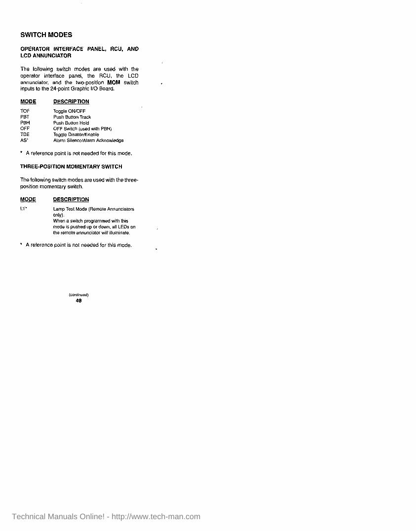
SWITCH MODES
OPERATOR INTERFACE PANEL, RCU, AND LCD ANNUNCIATOR
The following switch modes are used with the operator interface panel, the RCU, the LCD annunciator, and the two-position MOM switch inputs to the 24-point Graphic l/O Board.
MODE DESCRIPTION
TOF Toggle ON/OFF PBT Push Button Track PBH Push Button Hold OFF OFF Switch (used with PBH) TDE Toggle Disable/Enable AS Alarm Silence/Alarm Acknowledge
l A reference point is not needed for this mode.
THREE-POSITION MOMENTARY SWITCH
The following switch modes are used with the three- position momentary switch.
f-g@
LT
DESCRIPTION
Lamp Test Mode (Remote Annunciators only). When a switch programmed with this mode is pushed up or down, all LEDs on the remote annunciator will illuminate.
l A reference point is not needed for this mode.
(continued)
48
Technical Manuals Online! - http://www.tech-man.com
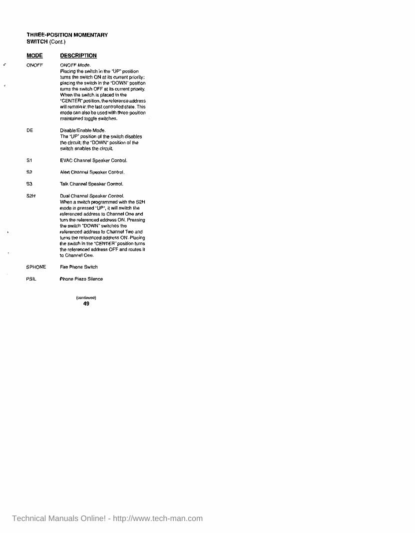
THREE-POSITION MOMENTARY SWITCH (Cont.)
MODE
ONOFF
DESCRIPTION
ONOFF Mode. Placing the switch in the “UP” position turns the switch ON at its current priority; placing the switch in the “DOWN” position turns the switch OFF at its current priority. When the switch is placed in the “CENTER”position. the reference address will remain in the last controlled state. This mode can also be used with three-position maintained toggle switches.
DE Disable/Enable Mode. The “UP” position of the switch disables the circuit; the “DOWN” position of the switch enables the circuit.
Si
52
53
S2H
EVAC Channel Speaker Control.
Alert Channel Speaker Control.
Talk Channel Speaker Control.
Dual Channel Speaker Control. When a switch programmed with the S2H mode is pressed “UP”, it will switch the referenced address to Channel One and turn the referenced address ON. Pressing the switch “DOWN” switches the referenced address to Channel Two and turns the referenced address ON. Placing the switch in the “CENTER” position turns the referenced address OFF and routes it to Channel One.
SPHONE Fire Phone Switch
PSIL Phone Piezo Silence
(continued) 49
Technical Manuals Online! - http://www.tech-man.com

THREE-POSITION MOMENTARY SWITCH (Cont.)
The following switch mode is used with audio system pseudo points in conjunction with manual control of audio tones or messages. However, use of this mode will not cause a manual override trouble condition.
MODE DESCRIPTION
HOA Placing the switch in the “UP” position turns the referenced address ON and the referenced address plus one OFF; placing the switch in the “DOWN” position turns the referenced address OFF and the referenced address plus one ON. Placing the switch in the “CENTEA” position turns the referenced address and the referenced address plus one OFF.
50
Technical Manuals Online! - http://www.tech-man.com
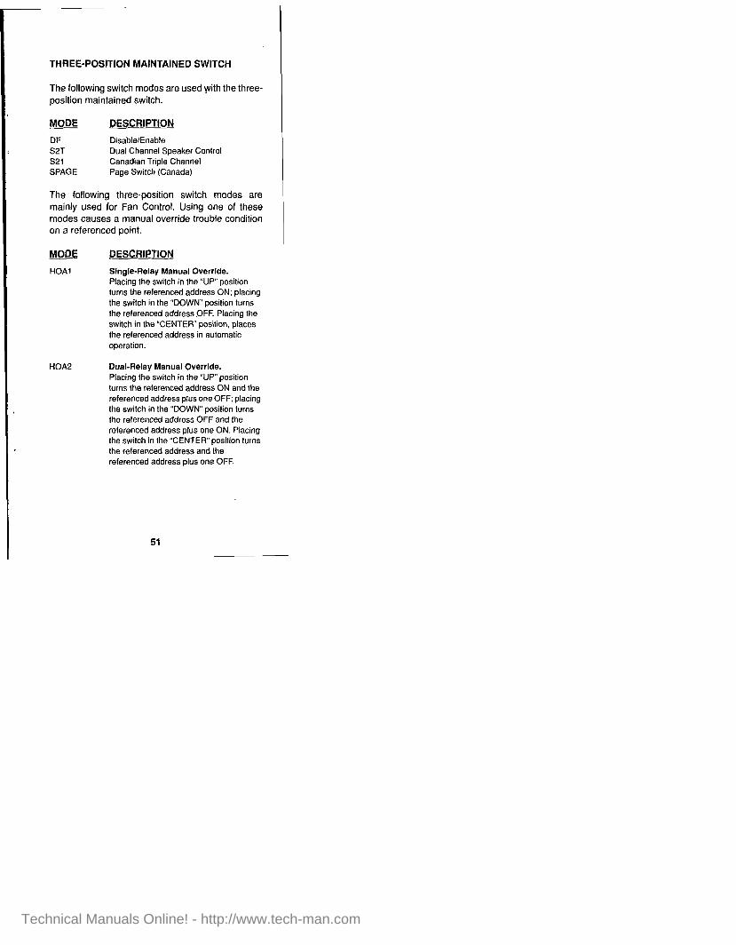
THREE-POSITION MAINTAINED SWITCH
The following switch modes are used with the three- position maintained switch.
MODE DESCRIPTION
DE Disable/Enable S2T Dual Channel Speaker Control s21 Canadian Triple Channel SPAGE Page Switch (Canada)
I
The following three-position switch modes are mainly used for Fan Control. Using one of these modes causes a manual override trouble condition on a referenced point.
MODE DESCRIPTION
HOAl Single-Relay Manual Override. Placing the switch in the “UP” position turns the referenced address ON; placing the switch in the “DOWN” position turns the referenced address OFF. Placing the switch in the “CENTER” position, places the referenced address in automatic operation.
HOA Dual-Relay Manual Override. Placing the switch in the “UP” position turns the referenced address ON and the referenced address plus one OFF; placing the switch in the “DOWN” position turns the referenced address OFF and the referenced address plus one ON. Placing the switch in the “CENTER” position turns the referenced address and the referenced address plus one OFF.
51
Technical Manuals Online! - http://www.tech-man.com

VALID REFERENCE POINTS FOR SWITCH MODES
Legend:
ALL = All 01 the following MIN = MAPNET II@ Input ANA = Analog Pseudo MON = Monitor Zone AUX = AUX Relay MOU = MAPNET @Output DIG = Digital Pseudo MSIG = Multi-Channel Signal GIN = Graphic Input SEN = Sensor w/Piezo/Relay
GOU = Graphic Output SIG = Signal Circuit LIS = Point list Pseudo
MODE VALID REFERENCE POINTS
ONOFF SIG, AUX, MOU, GOU, DIG, LIS OFF SIG, AUX, MOU, GOU, DIG, LIS TOF SIG, AUX, MOU, GOU, DIG, LIS PBT SIG, AUX, MOU, GOU, DIG, LIS PBH SIG, AUX, MOU, GOU, DIG, LIS HOAl SIG, AUX. MOU, GOU, DIG, LIS HOA SIG, AUX, MOU, GOU, DIG, LIS DE All except DIG and ANA TDE All except DIG and ANA SPHONE SIG, LIS Sl SIG, LIS s2 SIG, LIS S2T MSIG, LIS S2H MSIG, LIS 521 MSIG, LIS s3 SIG, LIS SPAGE MSIG, LIS LT Not Needed
l Not valid with Network External Points.
52
Technical Manuals Online! - http://www.tech-man.com

SPECIAL SWITCH AND LED MODES
The following special switch modes typically provide acknowledge, silence, and reset capabilities for remote annunciators.
NOTE: NO REFERENCE ADDRESS IS NEEDED.
MODE DESCRIPTION
CLACK Alert Mode Acknowledge LAACK Alarm Mode Acknowledge LSACK Supervisory Mode Acknowledge LTACK Trouble Mode Acknowledge LOACK Manual Override Mode Acknowledge AS Alarm Acknowledge/Silence LSS Alarm (Signal) Silence LSR System Reset
(continued)
53
Technical Manuals Online! - http://www.tech-man.com
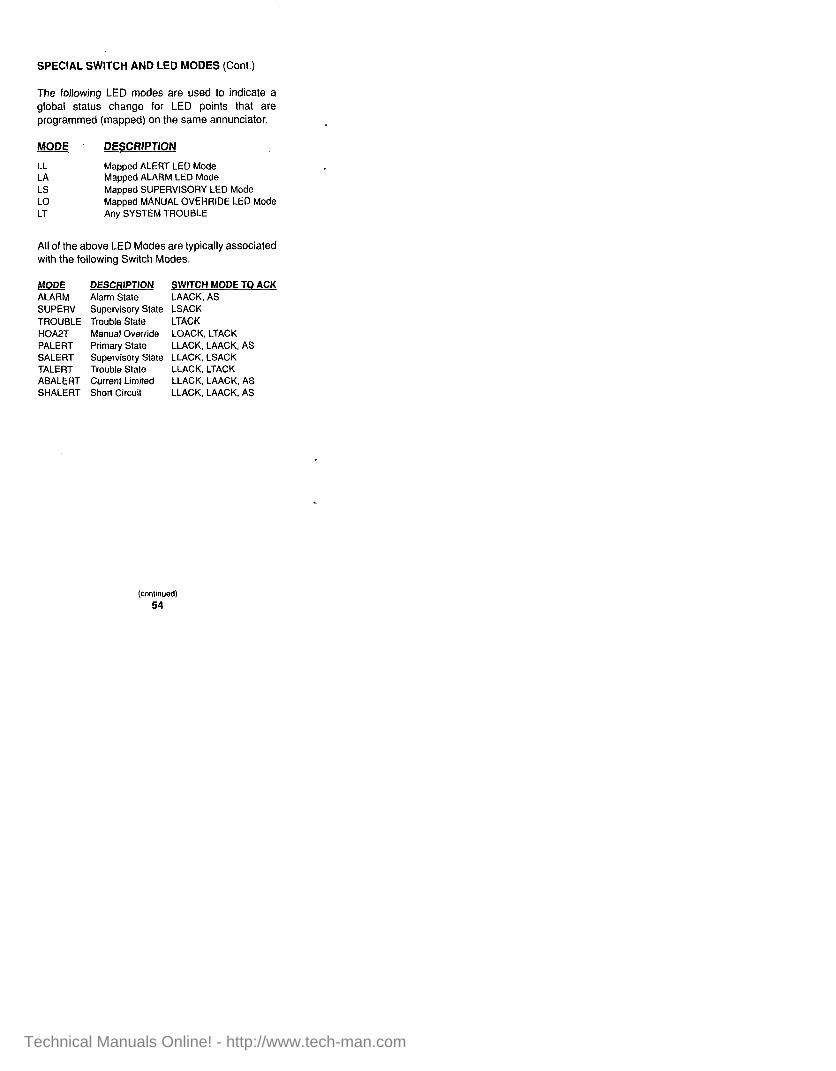
SPECIAL SWITCH AND LED MODES (Cont.)
The following LED modes are used to indicate a global status change for LED points that are programmed (mapped) on the same annunciator.
w DESCRIPTION
LL Mapped ALERT LED Mode LA Mapped ALARM LED Mode LS Mapped SUPERVISORY LED Mode LO Mapped MANUAL OVERRIDE LED Mode LT Any SYSTEM TROUBLE
All of the above LED Modes are typically associated with the following Switch Modes.
@.QQg DESCRlPTlON ALARM Alarm State SUPER’.’ Supervisory Stale TROUBLE Trouble State HOAPT Manual Override PALERT Primary State SALERT Supervisory State TALERT Trouble State ABALERT Current Limited SHALERT Short Circuit
SWITCH MODE TO ACK LAACK, AS LSACK LTACK LOACK, LTACK LLACK, LAACK, AS LLACK, LSACK LLACK, LTACK LLACK, LAACK, AS LLACK, LAACK, AS
(continued) 54
Technical Manuals Online! - http://www.tech-man.com

SPECIAL SWITCH AND LED MODES (Cont.)
The following LED programming modes require reference points.
MODE
HOAPT
DESCRIPTION
The HOA Switch Trouble Tracking Mode tracks the TROUBLE states of the two points. H)2A causes an alert if its reference point or the next consecutive reference point is in manual override trouble. It can be acknowledged with a switch mode of LOACK or LTACK al the annunciator. This condition can be acknowledged at the 4100 Operator Interface Panel, as well.
LED The LED Modetracks the state of another LED.
TRISTAT The TRISTAT Mode causes an LED to light when the reference point is in the abnormal (current-limited) state. The LED wil not turn OFF unless the reference point circuit status is shorted. This is a non-alert mode.
55
Technical Manuals Online! - http://www.tech-man.com

HIGH LEVEL MODES WITH LOW LEVEL CONVERSION
OPERATOR INTERFACE PANEL CONTROL KEY FUNCTIONS
The following functions are typically programmed to the Operator Interface Panel Control Keys. Since the Operator Interface Panel Control keys do not support high level modes, low level modes must be used. Although these functions are typically programmed at the Operator Interface Panel, they may be applied at a remote LED/switch annunciator or RCU if the conditions warrant. If programmed to an LED/annunciator, the appropriate programming mode must be applied according to the type of switch being used.
NOTE: RCUs do not support high level modes.
FUNCTION: CITY DISCONNECT High Level Mode: CD
Low Level Switch Mode: TOF; Reference Address: P34 Low Level LED Mode: TROUBLE; Reference Address: P34
FUNCTION: MANUAL EVACUATION High Level Mode: ME
Low Level Switch Mode: PBT; Reference Address: P35 Low Level LED Mode: ON; Reference Address: P48
FUNCTION: ELEVATOR BYPASS High Level Mode: EB
Low Level Switch Mode: TOF; Reference Address: P36 Low Level LEO Mode: TROUBLE; Reference Address: P36
FUNCTION: DOOR HOLDER BYPASS High Level Mode: DB
Low Level Switch Mode: TOF; Reference Address: P37 LOW Level LED Mode: TROUBLE; Reference Address: P37
(continued) 56
Technical Manuals Online! - http://www.tech-man.com

OPERATOR INTERFACE PANEL CONTROL KEY FUNCTIONS (Cont.)
FUNCTION: CONTROL POINT BYPASS Hlgh Level Mode: CB
Low Level Switch Mode: TOF; Reference Address: P38 Low Level LED Mode: TROUBLE: Reference Address: P38
OPERATOR INTERFACE PANEL FUNCTIONS
The following programming modes allow functions that are similar to those found on the Operator Interface Panel.
FUNCTION: ALARM SILENCE High Level Mode: SS
Low Level Switch Mode: LSS; Reference Address: N/A Low Level LED Mode: ON; Reference Address: P47
FUNCTION: SYSTEM RESET High Level Mode: SR
Low Level Switch Mode: LSR; Reference Address: N/A Low Level LED Mode: ON; Reference Address: Al4
FUNCTION: LOCAL ALERT ACKNOWLEDGE High Level Mode: LACK
LOW Level Switch Mode: LLACK; Reference Address: N/A Low Level LED Mode: LA: Reference Address: N/A
FUNCTION: LOCAL ALARM ACKNOWLEDGE High Level Mode: AACK
Low Level Switch Mode: LAACK; Reference Address: N/A Low Level LED Mode: LA; Reference Address: N/A
FUNCTION: LOCAL SUPV ACKNOWLEDGE High Level Mode: SACK
Low Level Switch Mode: LSACK; Reference Address: N/A Low Level LED Mode: LS; Reference Address: N/A
lmntinued) 57
Technical Manuals Online! - http://www.tech-man.com
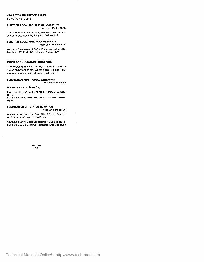
OPERATOR INTERFACE PANEL FUNCTIONS (Cont.)
FUNCTION: LOCAL TROUBLE ACKNOWLEDGE High Level Mode: TACK
Low Level Switch Mode: LTACK; Relerence Address: N/A Low Level LEO Mode: LT; Reference Address: N/A
FUNCTION: LOCAL MANUAL OVERRIDE ACK High Level Mode: OACK
Low Level Switch Mode: LOACK; Reference Address: N/A Low Level LED Mode: LO; Reference Address: N/A
POINT ANNUNCIATION FUNCTIONS
The following functions are used to annunciate the status of system points. Where noted, the high level mode requires a valid reference address.
FUNCTION: ALARMmROUBLE WITH ALERT High Level Mode: AT
Reference Address - Zones Only
Low Level LED #l Mode: ALARM; Reference Address: REFx Low Level LED #2 Mode: TROUBLE; Reference Address: REFx
FUNCTION: ON/OFF STATUS INDICATION High Level Mode: 00
Reference Address - ZN, SIG, AUX, FB, I/O, Pseudos, ANA Sensors w/Relay or Piezo Bases
Low Level LED #I Mode: ON; Reference Address: REFx Low Level LED #2 Mode: OFF; Reference Address: REFx
(continued)
58
Technical Manuals Online! - http://www.tech-man.com

POINT ANNUNCIATION FUNCTIONS (Cont.)
FUNCTION: ALARM/TROUBLE/DISABLE WITH STATUS High Level Mode: ATD
Reference Address - Zones Only Low Level Switch Mode: DE; Reference Address: REFx Low Level LED #l Mode: ALARM; Relerence Address: REFx Low Level LED #2 Mode: TROUBLE; Reference Address: REFx
NOTE: The associated switch will cause a zone disconnect/disable function.
MANUAL SYSTEM POINT CONTROL FUNCTIONS
The following functions allow for manual control of system points at their current priority levels. These High Level modes requires a valid reference address.
FUNCTION: CONTROL POINT TOGGLE HIGH LEVEL MODE: CT
Reference Address - SIG, AUX, Graphic Oulput, Digital Pseudo, ANA Sensor w/Output Base
Low Level switch mode: TOF; Reference Address: REFx Low Level LED mode: ON: Reference Address: REFx
FUNCTION: CONTROL WITH POSITIVE FEEDBACK HIGH LEVEL MODE: FT
Reference Address - AUX, Graphic Output Low Level switch mode: TOF; Reference Address: AUXx Low Level LED mode: ON; Reference Address: FBx
or Low Level switch mode: TOF; Reference Address: l/Ox Low Level LED mode: ON; Reference Address: t/Ox+1
(conlinued)
59
Technical Manuals Online! - http://www.tech-man.com

MANUAL SYSTEM POINT CONTROL FUNCTIONS (Cont.)
FUNCTION: ON/OFF CONTROL WITH TROUBLE HIGH LEVEL MODE: OT
Reference Address - SIG, AUX. Graphic Output, ANA Sensor w/Output Base
Low Level switch mode: ONOFF: Reference Address: REFx Low Level LED mode: TROUBLE; Reference Address: REFx
FUNCTION: CONTROL POINT ON/OFF WITH STATUS HIGH LEVEL MODE: C
Reference Address - SIG. AUX, Graphic Output, Digital Pseudo, ANA Sensor w/Output Base
Low Level switch mode: ONOFF; Reference Address: REFx Low Level LED #l mode: ON; Reference Address: REFx Low Level LED #2 mode: OFF; Reference Address: REFx
FUNCTION: CONTROL WITH POSITIVE FEEDBACK HIGH LEVEL MODE: F
Reference Address - AUX, Graphic Output
Low Level switch mode: ONOFF; Reference Address: AUXx Low Level LED mode: ON; Reference Address: FBx
or Low Level switch mode: ONOFF; Reference Address: I/Ox Low Level LED mode: ON; Reference Address: l/Ox+1
FUNCTION: CONTROL WITH ON/TRBL STATUS HIGH LEVEL MODE: OTC
Reference Address - SIG, AUX. Graphic Output. ANA Sensor w/Output Base
Low Level switch mode: ONOFF; Reference Address: REFx Low Level LED #l mode: ON; Reference Address: REFx LOW Level LED #2 mode: TROUBLE; Reference Address: REFx
60
Technical Manuals Online! - http://www.tech-man.com

MANUAL OVERRIDE OF SYSTEM POINT FUNCTIONS
The following functions are typically used in Fan Control applications where absolute control (manual override priority) is needed. These functions are commonly known as HOA modes, symbolizing Hand (manual ON), OFF (manual OFF), and Automatic (return to programmed control). These High Level modes require a valid reference address.
FUNCTION: SINGLE RELAY HOA W/O FEEDBACK HIGH LEVEL MODE: HOAlO
Reference Address - AUX, Graphic Output
Low Level switch mode: HOAI ; Reference Address: AUXx or l/Ox Low Level LED #I mode: ON; Reference Address: AUXx or VOX Low Level LED #2 mode: OFF; Reference Address: AUXx or I/Ox
FUNCTION: SINGLE RELAY HOA W/FEEDBACK HIGH LEVEL MODE: HOAII
Reference Address - AUX, Graphic butput
Low Level switch mode: HOAl ; Reference Address: AUXx or l/Ox Low Level LED #I mode: ON; Reference Address: FBx or l/Ox+1 Low Level LED #2 mode: OFF; Reference Address: FBx or l/Ox+1
61
Technical Manuals Online! - http://www.tech-man.com

MANUAL OVERRIDE OF SYSTEM POINT FUNCTIONS (Cont.)
FUNCTION: SINGLE RELAY HOAlDUAL FEEDBACK HIGH LEVEL MODE: HOA
Reference Address - AUX, Graphic Output
Low Level switch mode: HOAI ; Reference Address: AUXx Low Level LED #l mode: ON; Reference Address: FBx Low Level LED #2 mode: ON; Reference Address: FBxtl
Low Level switch mode: HOAI ; Reference Address: I/Ox Low Level LED #I mode: ABN; Reference Address: l/Ox+1 Low Level LED #2 mode: SHORT; Reference Address: I/ ox+1
FUNCTION: DUAL RELAY HOA W/O FEEDBACK HIGH LEVEL MODE: HOA
Reference Address - AUX, Graphic Output
Low Level switch mode: HOA2; Reference Address: AUXx or I/Ox Low Level LED #I mode: ON; Reference Address: AUXx or I/Ox Low Level LED #2 mode: ON; Reference Address: AUXx+i or l/Ox+1
FUNCTION: DUAL RELAY HOA WITH FEEDBACK HIGH LEVEL MODE: HOA
Reference Address - AUX, Graphic Output
Low Level switch mode: HOA2; Reference Address: AUXx or I/Ox i
Low Level LED #I mode: ON; Reference Address: FBx or l/Ox+2 Low Level LED #2 mode: OFF; Reference Address: FBx or l/Ox+2
(consnued) 62
Technical Manuals Online! - http://www.tech-man.com

MANUAL OVERRIDE OF SYSTEM POINT FUNCTIONS (Cont.)
FUNCTION: DUAL RELAY HOA/DUAL FEEDBACK HIGH LEVEL MODE: HOA
Reference Address - AUX, Graphic Output
Low Level switch mode: HOA2; Reference Address: AUXx Low Level LED #I mode: ON; Reference Address: FBx Low Level LED #2 mode: ON; Reference Address: FBxtl
Low Level switch mode: HOA2; Reference Address: I/Ox Low Level LED #I mode: ABN; Reference Address: l/Ox+2 Low Level LED #2 mode: SHORT: Reference Address: I/ ox+2
AUDIO SYSTEM CONTROL SWITCH FUNCTIONS
The following functions are related to 4100 Audio Systems.
FUNCTION: ALL SPEAKERS EVAC, HIGH LEVEL MODE: ASEVAC
Low Level switch.mode: HOA2; Reference Address: Pi41 Low Level LED mode: ON; Reference Address: Pi43
FUNCTION: EVACUATION TONE/MESSAGE HIGH LEVEL MODE: AEVAC
Low Level switch mode: HOA2; Reference Address: P87 Low Level LED mode: ON; Reference Address: P89
FUNCTION: ALERT TONE/MESSAGE HfGH LEVEL MODE: AALERT
Low Level switch mode: HOA2; Reference Address: PQO Low Level LED mode: ON; Reference Address: P92
(continued)
63
Technical Manuals Online! - http://www.tech-man.com
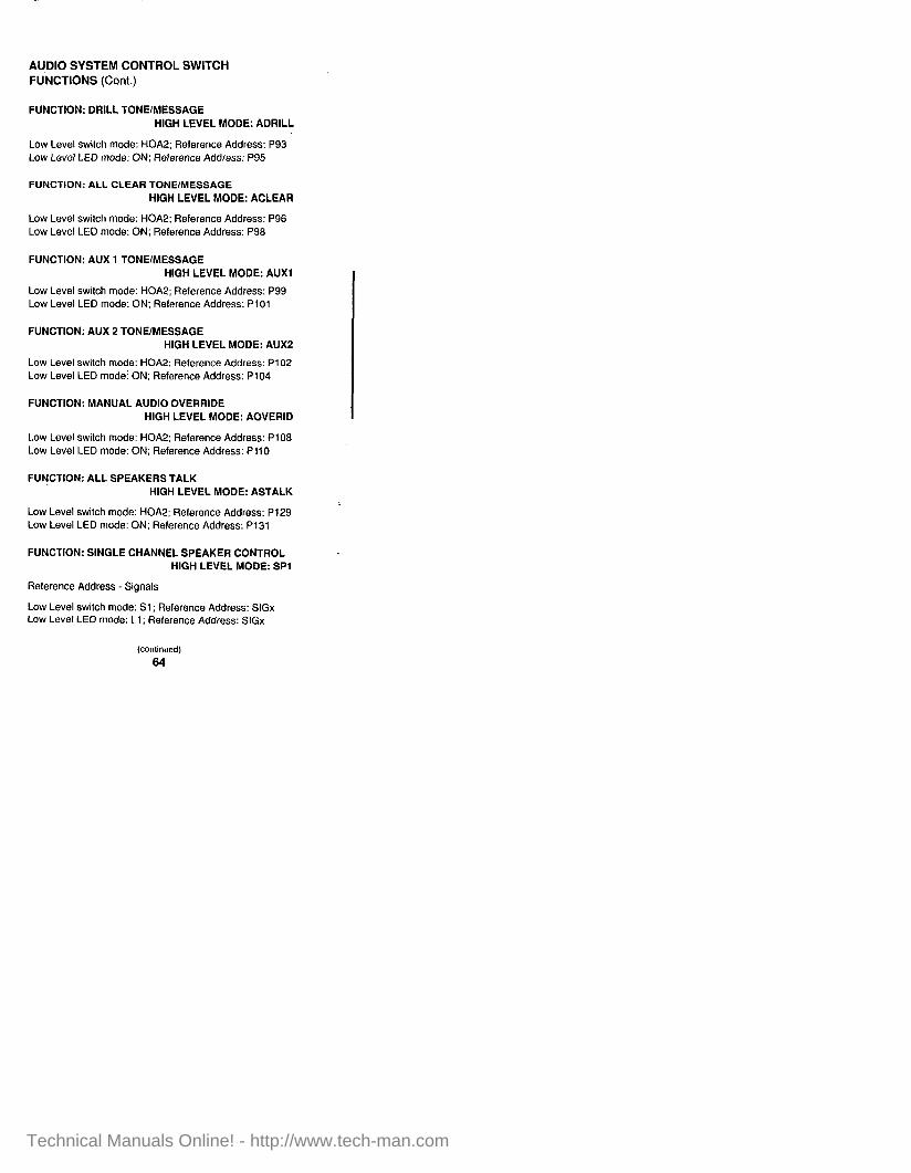
AUDIO SYSTEM CONTROL SWITCH FUNCTIONS (Cont.)
FUNCTION: DRILL TONE/MESSAGE HIGH LEVEL MODE: ADRILL
Low Level switch mode: HOA2; Reference Address: P93 Low Level LED mode: ON; Reference Address: P95
FUNCTION: ALL CLEAR TONE/MESSAGE
HIGH LEVEL MODE: ACLEAR
Low Level switch mode: HOA2; Reference Address: P96 Low Level LED mode: ON; Reference Address: P98
FUNCTION: AUX 1 TONE/MESSAGE HIGH LEVEL MODE: AUXl
Low Level switch mode: HOA2; Reference Address: PQQ Low Level LED mode: ON: Reference Address: PI01
FUNCTION: AUX 2 TONE/MESSAGE HIGH LEVEL MODE: AUX2
Low Level switch mode: HOA2; Reference Address: PI02 Low Level LED modei ON: Reference Address: PI04
FUNCTION: MANUAL AUDIO OVERRIDE HIGH LEVEL MODE: AOVERID
Low Level switch mode: HOA2; Reference Address: Pi08 Low Level LED mode: ON; Reference Address: PI10
FUbjCTtON: ALL SPEAKERS TALK HIGH LEVEL MODE: ASTALK
Low Level switch mode: HOA2; Relerence Address: P129 Low Level LED mode: ON; Reference Address: P131
FUNCTION: SINGLE CHANNEL SPEAKER CONTROL HIGH LEVEL MODE: SPl
Reference Address - Signals
Low Level switch mode: Sl ; Reference Address: SlGx Low Level LED mode: Ll; Reference Address: SlGx
64
Technical Manuals Online! - http://www.tech-man.com

AUDIO SYSTEM CONTROL SWITCH FUNCTIONS (Cont.)
FUNCTION: LOCAL SPEAKER TO CHANNEL 1 HIGH LEVEL MODE: Al LOCAL
Low Level switch mode: HOA2; Reference Address: PI23 Low Level LED mode: ON; Reference Address: P125
MULTI-CHANNEL AUDIO SYSTEM CONTROL SWITCH FUNCTIONS
The following functions are for multi-channel audio systems ONLY. Where noted certain High Level modes require a valid reference address.
FUNCTION: DUAL CHANNEL SPEAKER CONTROL HIGH LEVEL MODE: SP2
Reference Address - Signals
Low Level switch mode: S2T: Reference Address: SlGx Low Level LED #I mode: Ll ; Reference Address: SlGx Low Level LED #2 mode: L2; Reference Address: SlGx
FUNCTION: TRIPLE CHANNEL SPEAKER CONTROL HIGH LEVEL MODE: SP3
Reference Address Signals
Low Level switch #I mode: S2H: Reference Address: SlGx Low Level LED #I mode: Li ; Reference Address: SlGx Low Level LED #2 mode: L2; Reference Address: SlGx
or Low Level switch #2 mode: S3; Reference Address: SlGx Low Level LED #3 mode: L3; Reference Address: SlGx Low Level LED #4 mode: TROUBLE; Reference Address: SlGx
FUNCTION: ALL SPEAKERS MINUS TO TALK HIGH LEVEL MODE: AMINUS
Low Level switch mode: HOA2; Reference Address: Pill Low Level LED mode: ON; Reference Address: PI13
(continued)
65
Technical Manuals Online! - http://www.tech-man.com

MULTI-CHANNEL AUDIO SYSTEM CONTROL SWITCH FUNCTIONS (Cont.)
FUNCTION: ALL SPEAKERS TO CHANNEL 1 HIGH LEVEL MODE: AlSPEAK
Low Level switch mode: HOA2; Reference Address: P114 Low Level LED mode: ON; Reference Address: P116
FUNCTION: ALL SPEAKERS TO CHANNEL 2
HIGH LEVEL MODE: APSPEAK
Low Level switch mode: HOA2; Reference Address: Pi17 Low Level LED mode: ON; Reference Address: P119
FUNCTION: ALL SPEAKERS TO CHANNEL 3 HIGH LEVEL MODE: ASSPEAK
Low Level switch mode: HOA2; Reference Address: P120 Low Level LED mode: ON; Reference Address: P122
FUNCTION: LOCAL SPEAKER TO CHANNEL 2 HIGH LEVEL MODE: A2LOCAL
Low Level switch mode: HOA2; Reference Address: P126 Low Level LED mode: ON; Reference Address: P128
66
Technical Manuals Online! - http://www.tech-man.com

FIREFIGHTER’S PHONE SYSTEM FUNCTIONS
The following functions are related to 4100 Phone Systems.
FUNCTION: STANDARD PHONE CIRCUIT HIGH LEVEL MODE: P
Reference Address - Signals
Low Level switch mode: SPHONE; Reference Address: SlGx Low Level LED mode: LPHONE: Reference Address: SlGx
FUNCTION: PHONE PIE20 SILENCE SWITCH HIGH LEVEL MODE: PS
Low Level switch mode: PSIL; Reference Address: N/A Low Level LED mode: ON; Reference Address: PI54
FUNCTION: AUDIO/PHONE INTERFACE HIGH LEVEL MODE: APHONE
Low Level switch mode: HOA2; Reference Address: Pi05 Low Level LED mode: ON; Reference Address: P107
CANADIAN AUDIO SYSTEM FUNCTIONS
The following functions are related to Canadian Audio Systems.
FUNCTION: ALL EVAC HIGH LEVEL MODE: CAEVAC
Low Level switch mode: HOA2; Reference Address: P141 Low Level LED mode: ON; Reference Address: P143
FUNCTION: ALL ALERT (TRIPLE CHANNEL) HIGH LEVEL MODE: CAALRT3
Low Level switch mode: HOA2; Reference Address: P90 Low Level LED mode: ON; Reference Address: P92
(continued)
67
Technical Manuals Online! - http://www.tech-man.com

CANADIAN AUDIO SYSTEM FUNCTIONS (Cont.)
FUNCTION: ALL ALERT (SINGLE/DUAL CHANNEL) HIGH LEVEL MODE: CAALRTl
Low Level switch mode: HOA2; Reference Address: P90 Low Level LED mode: ON; Reference Address: P92
FUNCTION: ALL TALK HIGH LEVEL MODE: CTALK
Low Level switch mode: SPAGE; Reference Address: L90 Low Level LED mode: LPAGE: Reference Address: L90
FUNCTION: PAGE HIGH LEVEL MODE: PAGE
Reference Address: Signal, MAPNET lp Output
Low Level switch mode: SPAGE; Reference Address: REFx Low Level LED mode: LPAGE; Reference Address: REFx
66
Technical Manuals Online! - http://www.tech-man.com
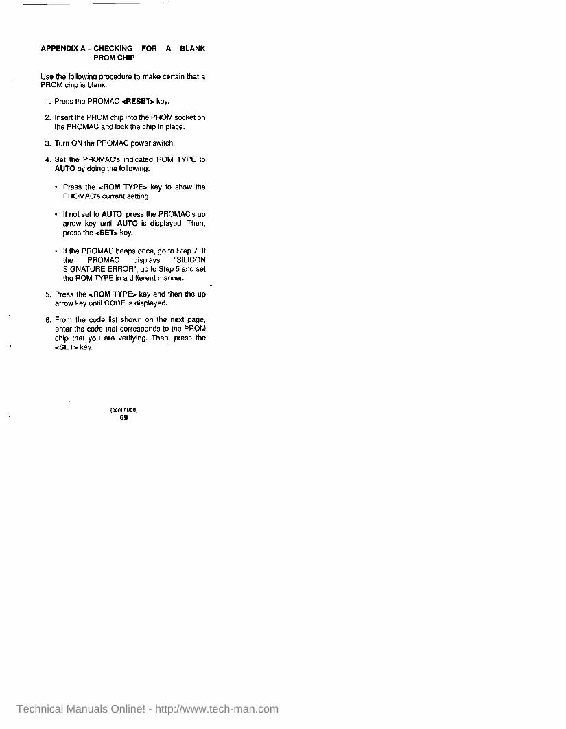
APPENDIX A-CHECKING FOR A BLANK PROM CHIP
Use the following procedure to make certain that a PROM chip is blank.
1. Press the PROMAC 4iESET> key.
2. Insert the PROM chip into the PROM socket on the PROMAC and lock the chip in place.
3. Turn ON the PROMAC power switch.
4. Set the PROMAC’s indicated ROM TYPE to AUTO by doing the following:
l Press the <ROM TYPE> key to show the PROMAC’s current setting.
l If not set to AUTO, press the PROMAC’s up arrow key until AUTO is displayed. Then, press the &ET> key.
l If the PROMAC beeps once, go to Step 7. If the PROMAC displays “SILICON SIGNATURE ERROR”, go to Step 5 and set the ROM TYPE in a different manner.
5. Press the <ROM TYPE> key and then the up arrow key until CODE is displayed.
6. From the code list shown on the next page, enter the code thal corresponds to the PROM chip that you are verifying. Then, press the <SET> key.
69
Technical Manuals Online! - http://www.tech-man.com

MANUFACTURER & PART NO. CODE
ATMEL - AT27C512R 1 DO03
FUJITSU - MBM27C512 512
HITACHI - HN27Ci 01 1 IA000
1 TAIWAN MICROCHIP - 27C512 I 5121 1 TEXAS INSTRUMENTS - TMS27C512 1 512 1
TOSHIBA - TC571000 1 DO05
NOTE: If the code for your PROM chip does not appear in the above code list, refer to the manual that came with the PROMAC for a more comprehensive code listing.
7. To verify that the PROM chip is blank, press the <DEVICE>, <BLANK>, and &ET> keys in that order.
l If the PROM chip is blank, the PROMAC displays PASS and beeps once.
l If the PROM chip is not blank, the PROMAC displays an error message and beeps several times. Perform the erasing procedure detailed in Appendix B below and the check for a blank PROM chip again using the above procedure.
APPENDIX B - ERASING A PROM CHIP
Use the following procedure to erase a PROM chip.
1. Remove the sticky label and any remaining glue from the window of the PROM chip.
(conlinued)
70
Technical Manuals Online! - http://www.tech-man.com

NOTE: Applying a small amount of isopropyl alcohol (Part No. 553-431) may help. However, do not leave any alcohol residue or fingerprints on the window of the PROM chip.
2. Place the PROM chip into the PROM eraser (Part No. 553-531) by positioning the PROM chip’s window over one of the openings in the PROM eraser’s base.
l Proper positioning of the PROM chip in the PROM eraser exposes the PROM chip to an ultraviolet light source when the eraser is turned ON.
3. Close the PROM eraser’s cover. (As a safety measure, eraser does not activate unless you close its cover.)
4. Adjust the timer on the front of the eraser to the maximum setting (approximately 7 minutes).
5. Slide the power switch to the ON position.
l The green indicator (on front of eraser) turns ON (indicating that the eraser’s timer is in progress). This indicator goes OFF when the timer shuts off.
NOTES: 1. To stop and then restart the eraser’s
timing sequence, open and then close the eraser’s cover before the timer indicator turns OFF.
2. In some cases, you may need to repeat the above procedure to completely erase the PROM chip. To make sure the PROM chip is blank after you erase it, follow the checking procedure in Appendix A.
71
Technical Manuals Online! - http://www.tech-man.com

APPENDIX C - PROM BURN PROCEDURE (Rev. 2.00 and earlier)
NOTE: To identify whether you have a Silicon or Non-silicon PROM chip, non-silicon chips are labeled MICROCHIP or ATMEL, AT27C512R; silicon chips are labeled ATMEL, AT27C512.
Non-Silicori PROM Chips
NOTE: If this procedure for non-silicon chips is not used, Error 27 (“Silicon Signature”) is eventually displayed on the PROMAC programmer.
Use the following procedure to burn Non-Silicon PROM chips.
1. Using the appropriate 4100 programmer software and portable computer, make the required job changes and then build the job via the appropriate JOB BUILD menu selection.
2. Once the build routine is completed, exit the 4100 programmer. REMEMBER TO SAVE YOUR CHANGES.
3. At the DOS Prompt (B>), change to Drive A by typing a: , and pressing <Enter>.
4. Insert the NEC MS-DOS disk into Drive A.
5. Type MODE COM1:9600,N,6,1 at the DOS Prompt (A>) and press <ENTER>.
6. Insert a Non-silicon Signature PROM into the PROMAO Programmer
7. Press the PROMAC’s <ROMTYPE> key.
(continued)
72
Technical Manuals Online! - http://www.tech-man.com

8. Using the PROMAC’s <s tr keys, select CODE. Then, press the &ET7 key.
9. Enter the appropriate code using the PROMAC’s numeric keys. Then, press the &ET> key.
10. Press the -zDEVICEr, <BLANK>, and <SET> keys in that order and wait for the PROMAC to display PASS.
11. Press the PROMAC’s <FUNCTION> key. Then, the PROMAC’s ~47 key.
l PROMAC should display [9600] 8BIT NON SPl.
12. Press the PROMAC’s <SET> key and wait for the PROMAC to display PASS.
13. Press the PROMAC’s <FUNCTION> key. Then, its 457 key.
l PROMAC should display MOTOROLA.
14. Press the PROMAC’s <SET7 key and wait for the PROMAC to display PASS.
15. Press the PROMAC’s <FUNCTION> key. Then, its <67 key.
l The PROMAC should display S-INPUT.
16. Press the PROMAC’s <SET> key.
l The PROMAC should display a flashing asterisk.
17. Change to Drive B by typing b: and pressing <ENTER> at the DOS Prompt (A=-).
18. Insert the job disk into Drive B.
(continued)
73
Technical Manuals Online! - http://www.tech-man.com

19. Type copy jobname.mot coml: at the DOS Prompt (B>). Then, press the <ENTER> key. (You have approximately two minutes to complete Step 19. If the PROMAC displays a “time out error”, repeat Step 15.)
NOTE: An example of a “jobname” is 806013A.
20. When the PROMAC displays PASS, press the <DEVICE>, <B.lJ.V.>, and &ET> keys in that order.
l When PROMAC again displays PASS, the Non-silicon Signature PROM is programmed and can be inserted into the 4100 Master Controller Board.
Silicon PROM Chips
Use the following procedure to burn Silicon PROM chips.
1. Highlight the Program/Download Main Menu item and press the <ENTER> key.
2. Select the Job Configuration PROM Burn submenu option and press <ENTER>.
3. Connect the PROMAC to the RS-232 port of the Programming Unit.
4. Set the PROMAC to [9600] 8BIT NON SPl by first pressing <FUNCTION 4 SET> and then pressing the <ENTER> key on the Programming Unit.
5. Set the PROMAC for remote control by first pressing <FUNCTION 9 SET> and then pressing the <ENTER> key on the Programming Unit.
(continued)
74
Technical Manuals Online! - http://www.tech-man.com

6. Insert a blank PROM chip into the PROMAC socket and press <ENTER> on the Programming Unit.
7. After the Programming Unit “beeps” four times, press the <ENTER> key.
8. After the PROMAC displays PASS and “beeps” once, press the <ENTER> key on the Programming Unit.
9. After a successful “burn,” the PROMAC will display PASS and a four-digit checksum.
10. Press the <ESC> key twice to return to the Main Menu.
APPENDIX D -INSTALLING THE PROGRAMMING UNIT SOFTWARE ON A HARD DRIVE
To install the Programming Unit software (Version 3.0 and later) on a hard drive, first insert the system disk (disk 1) into the A drive. Make sure that the A drive is the current drive. Next, enter the command INSTALL at the DOS prompt.
For example, if the floppy was in drive A, enter the following commands:
C:\>a: <ENTER> (changes the current drive to the A drive)
. A:\>instaM <ENTER> (runs the install program)
Technical Manuals Online! - http://www.tech-man.com

The install program first checks for the 4100 Programming Unit directory on the C drive. If it does not find the directory, it creates a 4100 Programming Unit directory. All of the files from the system disk (disk 1) are copied to the 4100 Programming Unit directory on the C drive. You are then prompted to insert the remaining program disks (one at a time) into the Adrive. After swapping the floppy disks and pressing <ENTER>, the remaining files are copied to the 4100 Programming Unit directory on the C drive.
NOTE: Beginning with Version 4 of the 4100 Programming Unit software the following actions are performed automatically, if you so desire.
You must enter C:\4100 to the path command in the root directory’s autoexec.bat file. (Consult the DOS Manual to edit this file). This allows you to run the 4100 Programming unit from any directory on the hard drive. In lieu of this method, you may set the PATH from the DOS prompt without affecting the autoexecbat file. To do so, enter the following command:
C:\> PATH = .;C:\4100;
The config.sys file in the root directory must contain certain information to ensure proper operation of the Programming Unit. (Consult the DOS Manual to edit this file.) If the config.sys file does not contain the following information, the system appears to work but does not execute a job build operation.
files = 32 buffers = 15 fcbs = 32,32 shell = command.com /p /e:800
(continued)
76
Technical Manuals Online! - http://www.tech-man.com

If you’re not in C drive, switch to the C drive by entering the following command at the DOS prompt:
A:\>c: <ENTER> (changes the current drive to the C drive)
You are encouraged to run the Programming unit from a directory other than the directory that contains the Programming Unit. For example, create a new directory called 4100JOBS in the following manner:
1. Type cd\ <ENTER> (Returns you to the Root directory)
2. Type md 4100jobs <ENTER:, (Makes a new directory called 41 OOJOEIS)
3. Type cd\4100jobs <ENTER> (Changes to the 41 OOJOBS directory)
4. Transfer the database file from the floppy disk to the hard disk using the DOS copy command as follows:
C:\>copy a:[filename.ext] <ENTER>
5. To run the 4100 Programming Unit, enter the following command:
C:\>41OOP6’ <ENTER>
l Or appropriate command.
Technical Manuals Online! - http://www.tech-man.com

To run the 4100 Programming Unit without copying the database file to the hard drive, follow the steps below:
1. Change the current drive to the A drive.
2. Place database disk into the A drive.
3. Type 4100 (or the appropriate startup command) and press <ENTER>.
NOTE: All database files will be sent out to the disk in drive A.
APPENDIX E - SAVING CHANGES TO AN EXISTING 4100 JOB
After completing all changes to an existing job:
1. Select the Save Current Job menu option from the Utilities menu.
l The Programming Unit automatically places the current filename into the entry window.
2. Change the last character in the filename to indicate modifications have been made to the original job (if not already done).
3. Press <ENTER>.
l A new database file, with the new filename, is saved to disk.
IMPORTANT: Should you need to modify the file, it must be called up by its new filename.
78
Technical Manuals Online! - http://www.tech-man.com

APPENDIX F - BACKING UP/ARCHIVING THE 4100 JOB
After completing all changes to an existing job:
1. Exit the Programming Unit from the Utilities Menu after you have saved the latest changes to the job. (See Appendix E.)
2. Generate a text file (the .DOC file) explaining your changes using the following procedure:
l Type ed filename.doc and then press <ENTER>.
l Press <F9> to create the file on the diskette.
l Type in information explaining the changes to this job. For example:
Time format was changed to 12 hour. Various custom labels were changed. Another 8-Zone monitor card was added to the system.
l Press <Flz and then <F2r.
3. Make backups of the data diskette for Headquarters (required) and Branch archiving (recommended). (See FSB263R.)
79
Technical Manuals Online! - http://www.tech-man.com

APPENDIX G -BACKING UP/ARCHIVING THE 4120 NETWORK JOB
After completing all changes to an existing 4120 Network job, you should back up your files with the NETBACK Utility. These files can be reinstalled in your computer at a later time using the NETINST Utility. (See Publication NET-41-003.)
To get help with these procedures, type netback or netinst at the DOS prompt and press <ENTER>.
NOTE: The name of the NETBACK “.LOG” file is the same as the “network name” mentioned in the HELP file.
80
Technical Manuals Online! - http://www.tech-man.com

Technical Manuals Online! - http://www.tech-man.com

t
Technical Manuals Online! - http://www.tech-man.com