Embed Size (px)
Citation preview
NC TURRET PUNCH PRESS
ARIES 222, 224
PROGRAMMING MANUAL
PRO-01198908
Copyright © 1998 by Amada Engineering & Service Co., Inc.14921 East Northam Street, La Mirada, CA 90638
All rights reserved. No part of this book shall be reproduced, stored in a retrieval system, or transmitted byany means, electronic, mechanical, photocopying, recording, or otherwise, without written permission fromthe publisher. No patent liability is assumed with respect to the use of the information contained herein.While every precaution has been taken in the preparation of this book, the publisher assumes noresponsibility for errors or omissions. Neither is any liability assumed for damages resulting from the useof the information contained herein.
CONTENTS
PROGRAMMING BASICS
PROCESS FOR THE PRODUCTS . . . . . . . . . . . . . . . . . . . . . . . . . . . . . . . . . . . . . . . l - lPROGRAMMING . . . . . . . . . . . . . . . . . . . . . . . . . . . . . . . . . . . . . . . . . . . . . . . . . . . . . . . 1 - 2CALCULATION OF COORDINATES . . . . . . . . . . . . . . . . . . . . . . . . . . . . . . . . . . . . . l - 3BASIC FUNCTION CODES . . . . . . . . . . . . . . . . . . . . . . . . . . . . . . . . . . . . . . . . . . . . . 1 - 4TAPE FORMAT . . . . . . . . . . . . . . . . . . . . . . . . . . . . . . . . . . . . . . . . . . . . . . . . . . . . . . 1 - 4G92 - ESTABLISHING COORDINATE SYSTEM . . . . . . . . . . . . . . . . . . . . . . . . . . . l - 4G90 - ABSOLUTE PROGRAMMING . . . . . . . . . . . . . . . . . . . . . . . . . . . . . . . . . . . . 1 -5.G91 - INCREMENTAL PROGRAMMING . . . . . . . . . . . . . . . . . . . . . . . . . . . . . . . . . . . l-!!-G70 - PUNCH OFF (NO PUNCHING) . . . . . . . . . . . . . . . . . .-. . . . . . . . . . . . . . . . . l - 5G27 - AUTO REPOSITIONING . . . . . . . . . . . . . . . . . . . . . . . . . . . . . . . . . . . . . . . . l - 6G25 - AUTO REPOSITIONING . . . . . . . . . . . . . . . . . . . . . . . . . . . . . . . . . . . . . . . . . . l - 7G50 - HOME RETRACT . . . . . . . . . . . . . . . . . . . . . . . . . . . . . . . . . . . . . . . . . . . . . . l - 7GO4 - DWELL . . . . . . . . . . . . . . . . . . . . . . . . . . . . . . . . . . . . . . . . . . . . . . . . . . . . . . . l - 7MOO - PROGRAM STOP . . . . . . . . . . . . . . . . . . . . . . . . . . . . . . . . . . . . . . . . . . . . . . 1-BMO1 - OPTIONAL STOP . . . . . . . . . . . . . . . . . . . . . . . . . . . . . . . . . . . . . . . . . . . . . . l - 8MO8 - PUNCH DELAY START, MO9 - PUNCH DELAY CANCEL..Ml2 - illBBLlNG START, Ml3 - NIBBLING CANCEL
. . . . . . . . l - 8. . . . . . . .:. . . . . . . . . . l - 9
TOO - DESIGNATION OF TOOL NUMBER . . . . . . . . . . . . . . . . . . . . . . . . . . . . . . l - 9No000 - SEQUENCE NUMBER . . . . . . . . . . . . . . . . . . . . . . . . . . . . . . . . . . . . . . l - 9FO - DESIGNATION OF AXIS FEED SPEED . . . . . . . . . . . . . . . . . . . . . . . . . . . . l - 1 0PROGRAM NAME . . . . . . . . . . . . . . . . . . . . . . . . . . . . . . . . . . . . . . . . . . . . . . . . . . . . l - 1 0PROGRAMMING PROCEDURE . . . . . . . . . . . . . . . . . . . . . . . . . . . . . . . . . . . . . . . . . l - l 1.HINTS ON PROCESSING . . . . . . . . . . . . . . . . . . . . . . . . . . . . . . . . . . . . . . . . . . . . . . l - 1 3CALCULATING LONG RECTANGULAR HOLE . . . . . . . . . . . . . . . . . . . . . . . :. . . l - 1 5CALCULATING LARGE RECTANGULAR. OPENING . . . . . . . . . . . . . . . . . . . . . . . l - 1 7CALCULATING RECTANGULAR OPENING WITH ROUNDED CORNERS . . . . . 1-19CALCULATING 45” NOTCH :. . . . . . . . . . . . . . . . . . . . . . . . . . . . . . . . . . . . . . . . . . 1-22HINTS ON PROGRAMMING . . . . . . . . . . . . . . . . . .;. . . . . . . . . . . . . . . . . . . . . . . . l - 2 5HINTS ON AUTO REPOSITIONING . . . . . . . . . . . . . . . . . . . . . . . . . . . . . . . . . . . . . l - 2 6
BASIC SOFTWARE . .--:
972 - DESIGNATION OF PATTERN ORIGIN . . . . . . . . . . . . . . . . . . . . . . . . . . . . 2 - l.....,
G28 - LINE AT ANGLE 2 - 2.I I’
. . . . . . . . . . . . . . . . . . . . . . . . . . . . . . . . . . . . . . . . . . . . . .G29 - ARC . . ..~....................................................2- 4G26 - BOLT HOLE CIRCLE . . . . . . . . . . . . . . . . . . . . . . . . . . . . . . . . . . . . . . . . . . . 2 - 6G36 - GRID-X, G37 - GRID-Y . . . . . . . . . . . . . . . . . . . . . . . . . . . . . . . . . . . . . . . 2 - 8G66 - SHEAR PROOF . . . . . . . . . . . . . . . . . . . .:. . . . . . . . . . . . . . . . . . . . . . . . . . . . . 2 -10G67 - SQUARE . . . . . . . . . . . . . . . . . . . . . . . . . . . . . . . . . . . . . . . . . . . . . . . . . . . . . 2 -12G68 - NIBBLING ARC . . .;. . . . . . . . . . . . . . . . . . . . . . . . . . . . . . . . . . . . . . . . . . . 2 -14G69 - NIBBLING LINE . . . . . . . . . . . . . . . . . . . . . . . . . . . . . . . . . . . . . . . . . . . . . . . 2 -16G78 - PUNCHING ARC . . . . . . . . . . . . . . . . . . . . . . . . . . . . . . . . . . . . . . . . . . . . . . . . . 2-18._G79 - PUNCHING LINE . . . . . . . . . . . . . . . . . . . . . . . . . . . . . .-. . . . . . . . . . . . . . . . 2 -20PATTERN MEMORY AND PATTERN RECALL ... . . . . . . . . . . . . . . . . . . . . . . . . . . 2-21
G93 - OFFSET . . . . . . . . . . . . . . . . . . . . . . . . . . . . . . . . . . . . . . . . . . . . . . . . . . . . . . . 2 -23MACRO FUNCTION . . . . . . . . . . . . . . . . . . . . . . . . . . . . . . . . . . . . . . . . . . . . . . . . . . 2 -25BLOCK DELETION . . . . . . . . . . . . . . . . . . . . . . . . . . . . . . . . . . . . . . . . . . . . . . . . . . . 2 -29INPUT OF DECIMAL POINT . . . . . . . . . . . . . . . . . . . . . . . . . . . . . . . . . . . . . . . . . . . 2 -29
MULTIPLE PART PUNCHING
GENERAL DESCRIPTION.AND PROGRAMMING EXAMPLE . . . . . . . . . . . . . . . . 3-lG98 - SETTING OF REFERENCE POINT AND LAYOUT FOR
MULTIPLE PART PUNCHING’ . . . . . . . . . . . . . . . . . . . . . . . . . . . . . . . . . . . 3-4,. I.:.. UOO TO Voo - STORING OF PART PROGRAM . . . . . . . . . . . . . . . .,. _. . . . . 3-8
I.,.,:’
G75, G76 Woo 00 - RECALLING AND EXECUTION OFPART PROGRAM . . . . . . . . . _ . . . . _. . . . . . . . _ _. . . . . . . 3-10
TRIAL PUNCHING, POST-TRIAL PUNCHING, AND FULL PUNCHING . . . . . . . 3-14
CLAMP DEAD ZONE DIAGRAM
CLAMP DEAD ZONE . . . . . . . . . . . . . . . . . . . . . . . . . . . . . . . . . . . . . . . . . . . . . . . . . 4 - lHOW TO USE DEAD ZONE DIAGRAMS . . . . . . . . . . . . . . . . . . . . . . . . . . . . . . . . 4 - 2DEAD ZONE DIAGRAMS . . . . . . . . . . . . . . . . . . . . . . . . . . . . . . . . . . . . . . . . . . . . . . 4 - 3
(APPENDIX) ‘PROGRAMMING EXAMPLE
EX. 1 GENERAL PUNCHING . . . . . . . . . . . . . . . . . . . . . . . . . . . . . . . . . . . . . . . . . . . 5-1EX. 2 PUNCHING WITH AUTO REPOSITIONING . . . . . . . . . . . . . . . . . . . . . . . . . 5 - 5EX. 3 MULTIPLE PART PUNCHING . . . . . . . . . . . . . . . . . . . . . . . . . . . . . . . . . . . . . . . 5-11EX. 4 GENERAL PUNCHING (Example of plotting data entry) . . . . . . . . . . . . . . . . 5-20
-
(APPENDIX) DISPLAYED FORMAT ON CRT.. . . . . . . . . . . . . . . . . . . . . . . . . . . . 6-l
. .
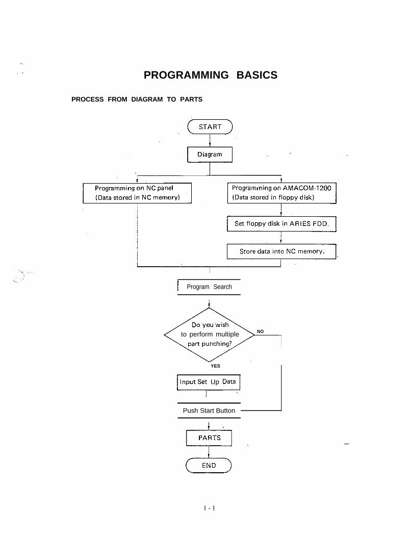
. . _1 PROGRAMMING BASICS
PROCESS FROM DIAGRAM TO PARTS
I Program Search
to perform multiple NO
/ YES
1 lyputse; Up Data.1
Push Start ButtonI-
l - l
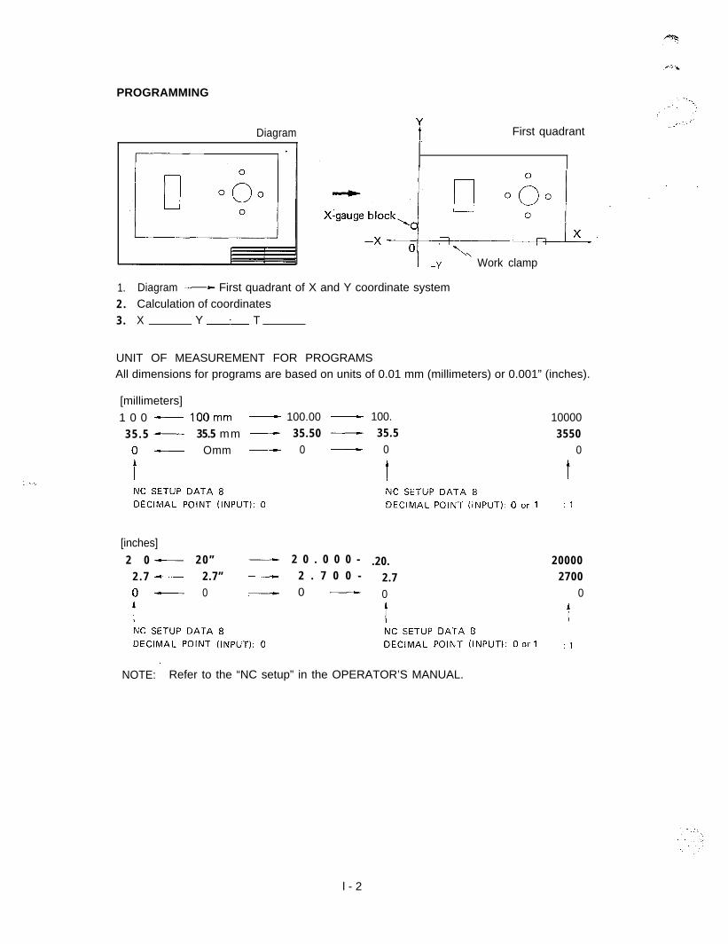
PROGRAMMING
Diagram
1. Diagram - First quadrant of X and Y coordinate system2 . Calculation of coordinates3 . X YAT
iFirst quadrant
i .-y ’ Work clamp
UNIT OF MEASUREMENT FOR PROGRAMSAll dimensions for programs are based on units of 0.01 mm (millimeters) or 0.001” (inches).
[millimeters]
1 0 0 - 1OOmm - 100.00 - 100. 100003 5 . 5 - 35.5 mm - 35.50 - 35.5 3550
o- Omm - 0 - 0 0
i ! tNC SETUP DATA 8 NC SETUP DATA 8DECIMAL POINT (INPUT): 0 DECIMAL POINT (INPUT): 0 or 1 : 1
[inches]
2 0 - 2 0 ” - 2 0 . 0 0 0 - .20. 200002 . 7 - 2.7” - 2 . 7 0 0 - 2.7 2700o- 0 .- 0 - 0 0
tNC SETUP DATA 8 NC SETUP DATA 8DECIMAL POINT (INPUT): 0 DECIMAL POINT (INPUT): 0 or 1 : 1
,NOTE: Refer to the “NC setup” in the OPERATOR’S MANUAL.
l - 2
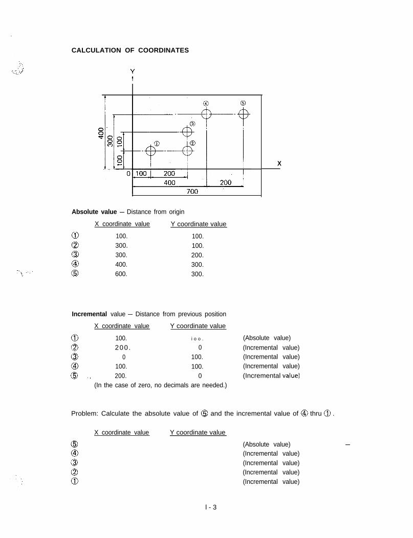
CALCULATION OF COORDINATES
Absolute value - Distance from origin
X coordinate value
100.300.300.400.600.
Y coordinate value
100.100.200.300.300.
X
Incremental value - Distance from previous position
X coordinate value Y coordinate value
a 100. i o o . (Absolute value)
QJ 200 . 0 (Incremental value)
c3 0 100. (Incremental value)
co 100. 100. (Incremental value)
0 ./ 200. 0 (Incremental va.lue)(In the case of zero, no decimals are needed.)
Problem: Calculate the absolute value of @ and the incremental value of @ thru @ .
X coordinate value Y coordinate value
(Absolute value)(Incremental value)(Incremental value)(Incremental value)(Incremental value)
-
l - 3
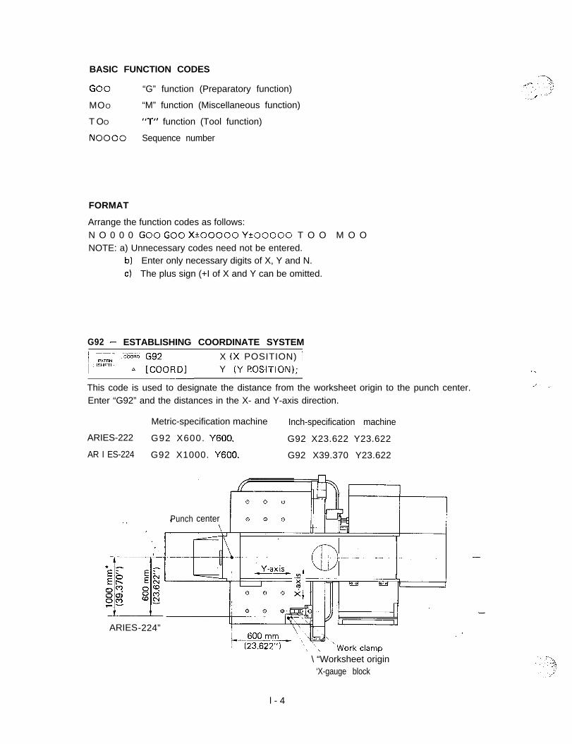
BASIC FUNCTION CODES
GO0 “G” function (Preparatory function)
MOO “M” function (Miscellaneous function)
T OO ‘7” function (Tool function)
NO000 Sequence number
FORMAT
Arrange the function codes as follows:N O 0 0 0 GO0 Go0 X*00000 Y+OOOOO T O O M O ONOTE: a) Unnecessary codes need not be entered.
b) Enter only necessary digits of X, Y and N.c) The plus sign (+I of X and Y can be omitted.
G92 - ESTABLISHING COORDINATE SYSTEM) ;;z .c&Gb Gg2 X (X POSITION) /
I’““‘? A [COORDI Y (Y F!OSITION); 1-__
This code is used to designate the distance from the worksheet origin to the punch center.Enter “G92” and the distances in the X- and Y-axis direction.
Metric-specification machine Inch-specification machine
ARIES-222 G92 X600. Y600. G92 X23.622 Y23.622
AR I ES-224 G92 X1000. Y600. G92 X39.370 Y23.622
ARIES-224”
0 0 0
Punch center 0 0 8
\ “Worksheet origin‘X-gauge block
l - 4
-?..!\.. _.,:
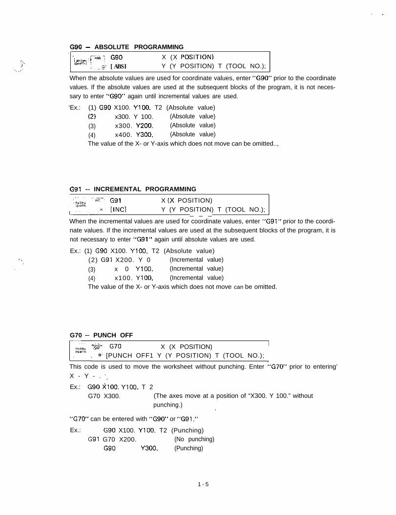
G90 - ABSOLUTE PROGRAMMING’ : ---.. t-is/
i mmr4 ! ’GgO X (X POSITiON)
,SHlFT,/ I: .--~_G_l [ABSI Y (Y POSITION) T (TOOL NO.);
When the absolute values are used for coordinate values, enter “G90” prior to the coordinatevalues. If the absolute values are used at the subsequent blocks of the program, it is not neces-sary to enter “G90” again until incremental values are used.
‘Ex.: (1) G90 X100. YlOO. T2 (Absolute value)
(2) x300. Y 100. (Absolute value)
(3) x300. Y200. (Absolute value)
(4) x400. Y300. (Absolute value)
The value of the X- or Y-axis which does not move can be omitted..,
G91 - INCREMENTAL PROGRAMMING
.- i,_I
”
X (X POSITION)Y (Y POSITION) T (TOOL NO.);_ _ _
When the incremental values are used for coordinate values, enter “G91“ prior to the coordi-nate values. If the incremental values are used at the subsequent blocks of the program, it isnot necessary to enter “G91” again until absolute values are used.
Ex.: (1) G90 X100. YlOO. T2 (Absolute value)(2) G91 X200. Y 0 (Incremental value)
(3) x 0 YlOO. (Incremental value)
(4) x100. YIOO. (Incremental value)The value of the X- or Y-axis which does not move can be omitted.
G70 - PUNCH OFF
‘$$I- G70 X (X POSITION). ..e’ [PUNCH OFF1 Y (Y POSITION) T (TOOL NO.); j
This code is used to move the worksheet without punching. Enter “G70” prior to entering’
X - Y - . I,
Ex.: G90 >i;lOO. YlOO. T 2G70 X300. (The axes move at a position of “X300. Y 100.” without
punching.) ,
“G70” can be entered with “G90” or “G91.”
Ex.: G90 X100. YlOO. T2 (Punching)G91 G70 X200. (No punching)
G90 Y300. (Punching)
1 - 5
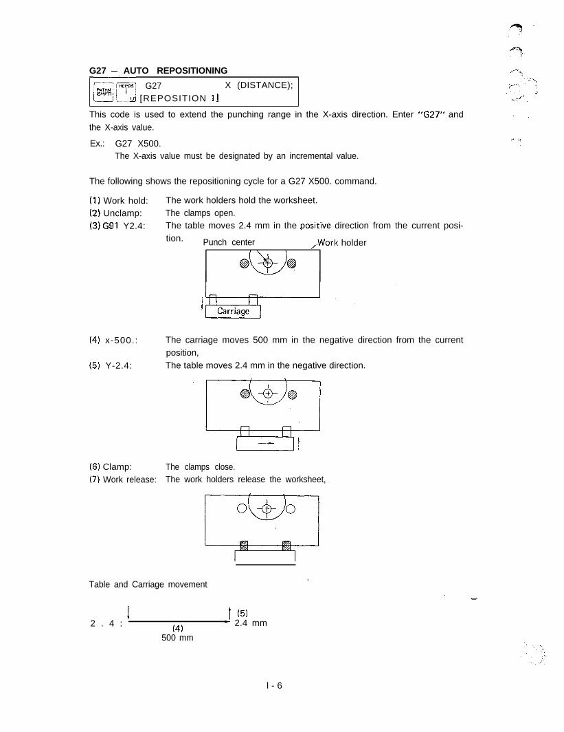
G27 - AUTO REPOSITIONING
[Z/‘--=yG27 X (DISTANCE);
I--u [REPOSITION 11
This code is used to extend the punching range in the X-axis direction. Enter “G27” andthe X-axis value.
Ex.: G27 X500.The X-axis value must be designated by an incremental value.
The following shows the repositioning cycle for a G27 X500. command.
(I) Work hold:(2) Unclamp:(3) G91 Y2.4:
(41 x-500.: The carriage moves 500 mm in the negative direction from the currentposition,
(5) Y-2.4: The table moves 2.4 mm in the negative direction.
(6) Clamp:(7) Work release:
The work holders hold the worksheet.The clamps open.The table moves 2.4 mm in the posi‘tive direction from the current posi-tion. Punch center ,Work holder
-8 @?
The clamps close.The work holders release the worksheet,
Table and Carriage movement,
2 . 4 : ’1 (5)- 2.4 mm
(41500 mm
l - 6
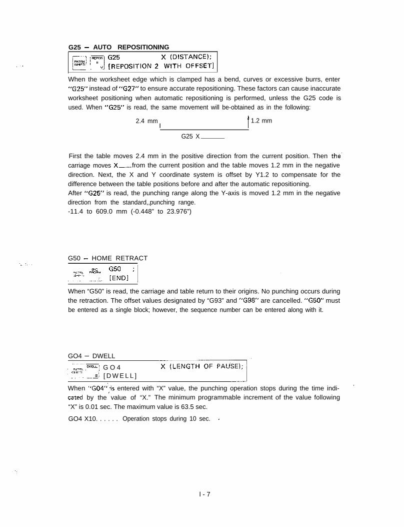
G25 - AUTO REPOSITIONING
IF] 13 ~~~PoSITICIN 2 xW!TD~~~EE~I
When the worksheet edge which is clamped has a bend, curves or excessive burrs, enter“G25” instead of “G27” to ensure accurate repositioning. These factors can cause inaccurate
worksheet positioning when automatic repositioning is performed, unless the G25 code isused. When “G25” is read, the same movement will be-obtained as in the following:
2.4 mmI t
1.2 mm
G25 X
First the table moves 2.4 mm in the positive direction from the current position. Then the-carriage moves X--from the current position and the table moves 1.2 mm in the negativedirection. Next, the X and Y coordinate system is offset by Y1.2 to compensate for thedifference between the table positions before and after the automatic repositioning.After “G25” is read, the punching range along the Y-axis is moved 1.2 mm in the negativedirection from the standard,,punching range.-11.4 to 609.0 mm (-0.448” to 23.976”)
G50 i HOME RETRACT
When “G50” is read, the carriage and table return to their origins. No punching occurs duringthe retraction. The offset values designated by “G93” and “G98” are cancelled. “G50” mustbe entered as a single block; however, the sequence number can be entered along with it.
GO4 - DWELL
1 -~--pAT+yp., ,Dw”u-: G O 41 ““i. -E[ [ D W E L L ]1When “G04”‘,!s entered with “X” value, the punching operation stops during the time indi- ’cated by the value of “X.” The minimum programmable increment of the value following“X” is 0.01 sec. The maximum value is 63.5 sec.
GO4 X10. . . . . . Operation stops during 10 sec. I
l - 7
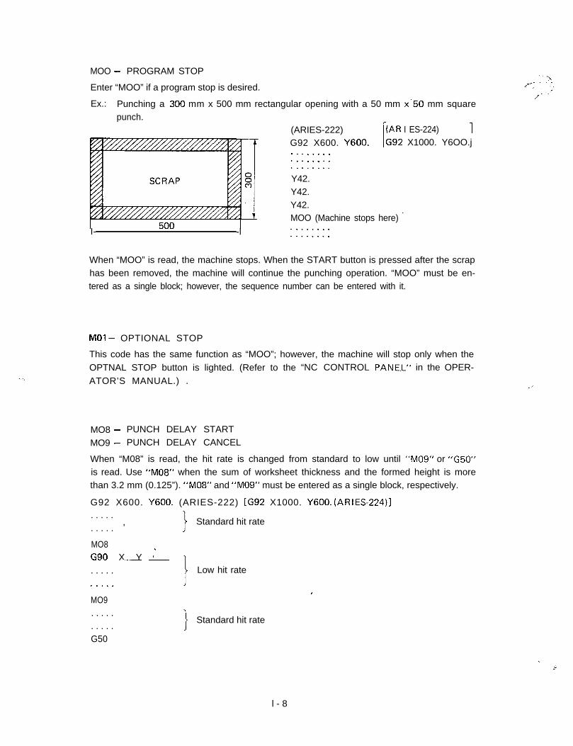
MOO - PROGRAM STOP: ;-- \
Enter “MOO” if a program stop is desired.
Ex.: Punching a -300 mm x 500 mm rectangular opening with a 50 mm x.50 mm squarepunch.
I- -l
(ARIES-222) [(AR I ES-224) 1
G92 X600. Y600. LG92 X1000. Y6OO.j........................Y42.Y42.Y42.MOO (Machine stops here) .’................
When “MOO” is read, the machine stops. When the START button is pressed after the scraphas been removed, the machine will continue the punching operation. “MOO” must be en-tered as a single block; however, the sequence number can be entered with it.
MO1 - OPTIONAL STOP
This code has the same function as “MOO”; however, the machine will stop only when theOPTNAL STOP button is lighted. (Refer to the “NC CONTROL PANE.L” in the OPER-
ATOR’S MANUAL.) . .,
MO8 - PUNCH DELAY START
MO9 - PUNCH DELAY CANCEL
When “M08” is read, the hit rate is changed from standard to low until “M09” or “G50”is read. Use “M08” when the sum of worksheet thickness and the formed height is morethan 3.2 mm (0.125”). “M08” and “M09” must be entered as a single block, respectively.
G92 X600. Y600. (ARIES-222) [G92 X1000. Y600. (ARIES-224)]. . . . .
, Standard hit rate. . . . .
MO8G90 X Y )’- -. . . . . Low hit rate
MO9. . . . .. . . . .G50
Standard hit rate
.
.:‘.
l - 8
M l 2 - .NIBBLING STARTM l 3 - NIBBLING CANCEL
When “Ml 2” is read, nibbling is performed until “Ml 3” is read. In nibbling, the press clutchis always engaged with the brake released. “M12” and “M13” must be entered as a single
block, respectively. Pattern punching cannot be commanded between Ml2 and Ml3
. . . . .
M l2G90 X-YG91 X-..eG91 X.-m.-G91 X-M l 3. . . . .. . . . .
Nibbling [Hole intervals should be 6 mm (0.236”) or less.]
TOO - DESIGNATION OF TOOL NUMBER
This code is used. to designate the tool station number in order to select the tool to be used.If the same tool is to be used continuously, it is not necessary to enter this code again until adifferent tool is needed.
Ex.: G92 X600. Y600. (ARIES-222) [G92 X1000. Y600. (ARIES-224)]G90 X450. Y300. T2G91 X50.00 (T2 not required)
x50.00 . (T2 not required)G90 X500. Y450. T3
N.0000 - SEQUENCE NUMBER
Any numeral (from 1 to 9999), with four or less digits, beginning with “N” can be enteredat the beginning of each block. This code is used for indexing each block.
Ex.:” G92 X600. Y600. (ARIES-222) [G92 X1000. Y600. (ARIES-224)]NOdql G90 X450. Y300. T 2 .NO002 G91 X 5 0 .NO003 x50.NO004 G90 X500. Y450. T3N9999 G50 ,
The sequence number need not be entered if it is not necessary. Entry at key points-
instead of all blocks will be useful.Zeros which directly follow “N” may be omitted.
1-9
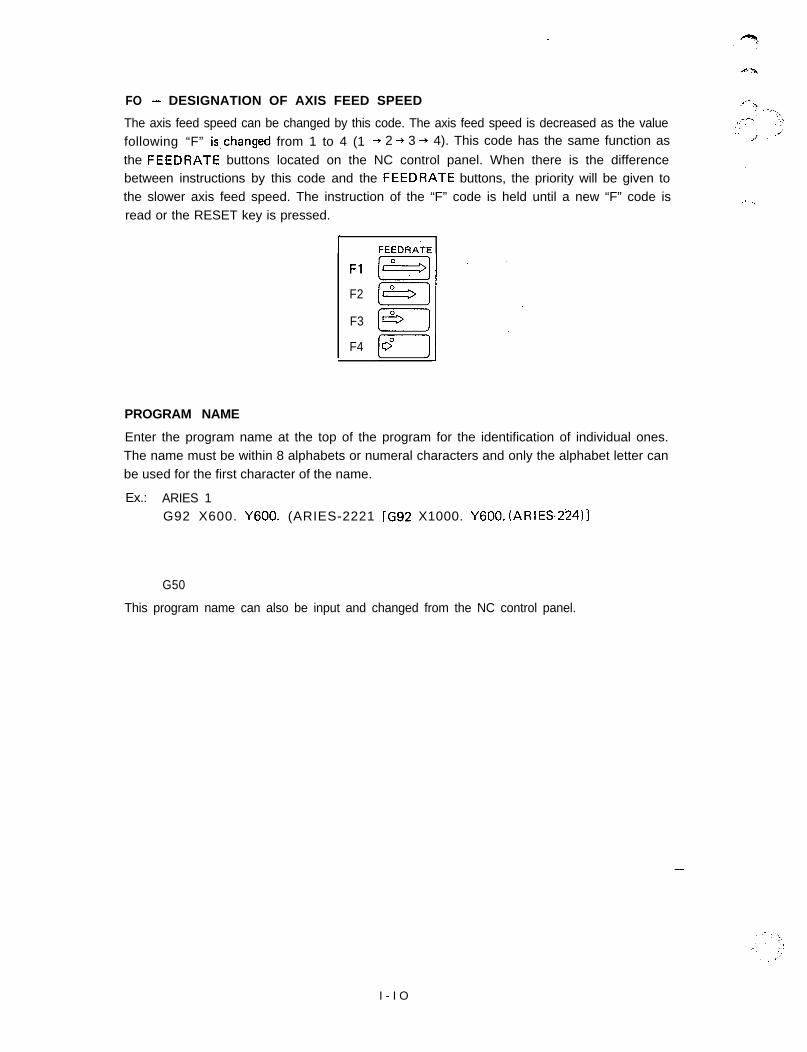
FO - DESIGNATION OF AXIS FEED SPEED
The axis feed speed can be changed by this code. The axis feed speed is decreased as the valuefollowing “F” is,changed from 1 to 4 (1 + 2 + 3 + 4). This code has the same function as
the FEEDRATE buttons located on the NC control panel. When there is the differencebetween instructions by this code and the FEEDRATE buttons, the priority will be given tothe slower axis feed speed. The instruction of the “F” code is held until a new “F” code isread or the RESET key is pressed.
I FEEDRATE
Fl
F2
F3
F4
PROGRAM NAME
Enter the program name at the top of the program for the identification of individual ones.The name must be within 8 alphabets or numeral characters and only the alphabet letter canbe used for the first character of the name.
Ex.: ARIES 1G92 X600. Y600. (ARIES-2221 [G92 X1000. Y600. (ARIES224)l
G50
This program name can also be input and changed from the NC control panel.
-
I - I O
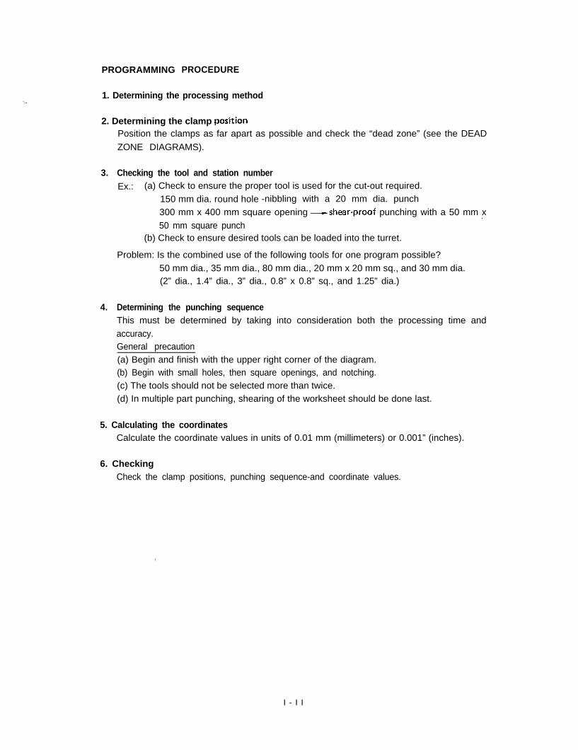
PROGRAMMING PROCEDURE
1. Determining the processing method
2. Determining the clamp posZtionPosition the clamps as far apart as possible and check the “dead zone” (see the DEAD
ZONE DIAGRAMS).
3. Checking the tool and station numberEx.: (a) Check to ensure the proper tool is used for the cut-out required.
150 mm dia. round hole -nibbling with a 20 mm dia. punch300 mm x 400 mm square opening Ushear-proof punching with a 50 mm x.-50 mm square punch
(b) Check to ensure desired tools can be loaded into the turret.
Problem: Is the combined use of the following tools for one program possible?50 mm dia., 35 mm dia., 80 mm dia., 20 mm x 20 mm sq., and 30 mm dia.(2” dia., 1.4” dia., 3” dia., 0.8” x 0.8” sq., and 1.25” dia.)
4. Determining the punching sequenceThis must be determined by taking into consideration both the processing time andaccuracy.General precaution(a) Begin and finish with the upper right corner of the diagram.(b) Begin with small holes, then square openings, and notching.(c) The tools should not be selected more than twice.(d) In multiple part punching, shearing of the worksheet should be done last.
5. Calculating the coordinatesCalculate the coordinate values in units of 0.01 mm (millimeters) or 0.001” (inches).
6. CheckingCheck the clamp positions, punching sequence-and coordinate values.
,
I - I I
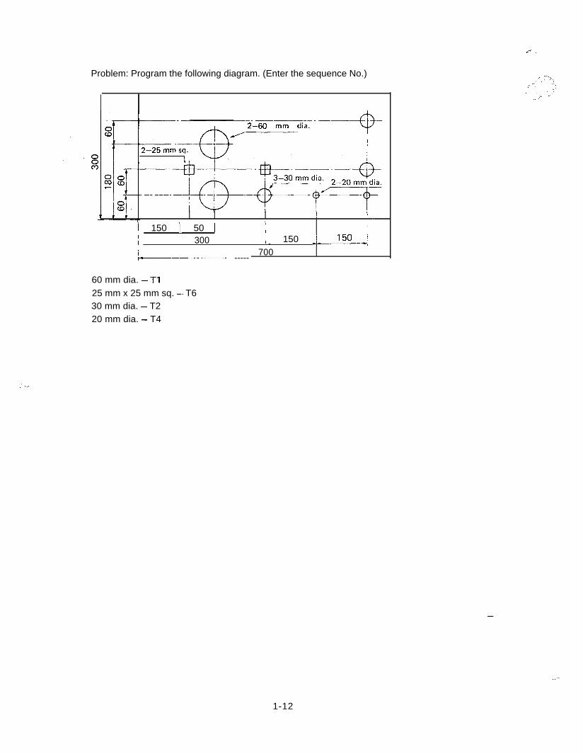
Problem: Program the following diagram. (Enter the sequence No.)
// 700r------ -----
2-60 mm dia.
, II -
I 150 I. 50 I/ ,I
I/ 300 ,. 150 l-.-~
60 mm dia. - Tl25 mm x 25 mm sq. - T630 mm dia. - T220 mm dia. - T4
-
..”
1-12
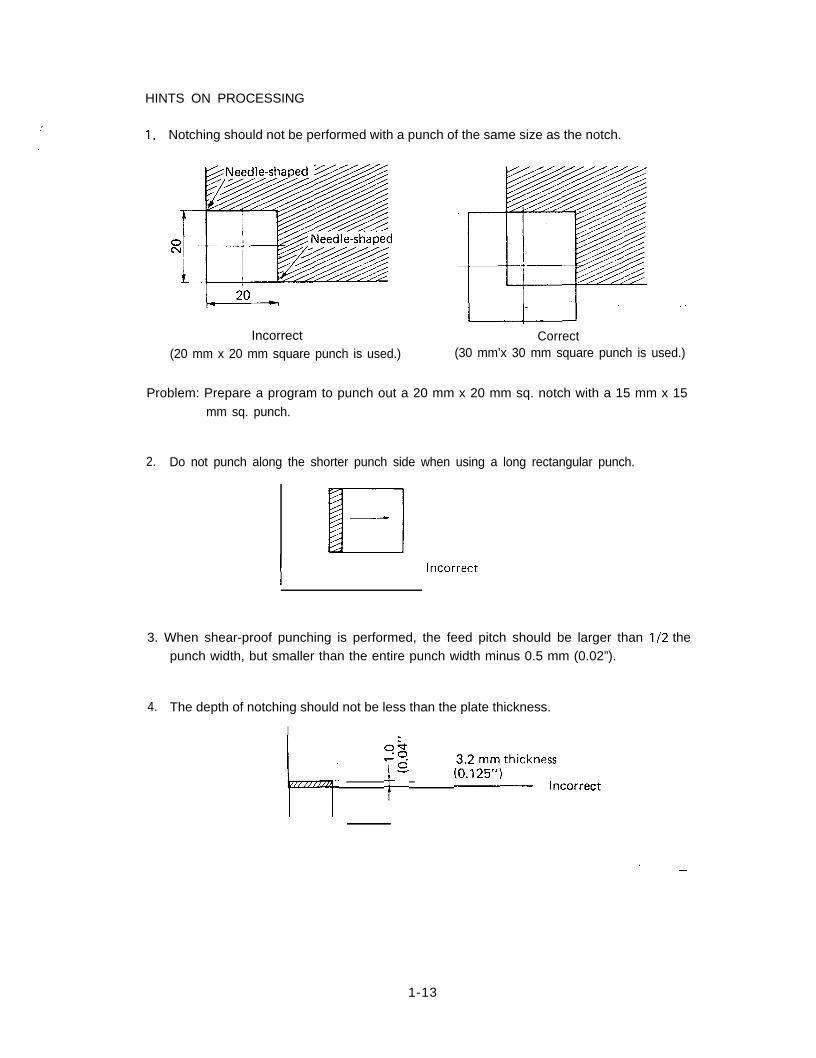
HINTS ON PROCESSING
:
. . .1. Notching should not be performed with a punch of the same size as the notch.
Incorrect Correct(20 mm x 20 mm square punch is used.) (30 mm’x 30 mm square punch is used.)
Problem: Prepare a program to punch out a 20 mm x 20 mm sq. notch with a 15 mm x 15mm sq. punch.
2. Do not punch along the shorter punch side when using a long rectangular punch.
incorrect
3. When shear-proof punching is performed, the feed pitch should be larger than l/2 thepunch width, but smaller than the entire punch width minus 0.5 mm (0.02”).
4. The depth of notching should not be less than the plate thickness.
I
/il.,~ p (30:;y,thickrm:correct
1-13
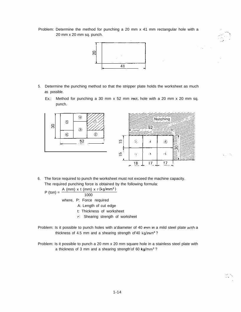
Problem: Determine the method for punching a 20 mm x 41 mm rectangular hole with a20 mm x 20 mm sq. punch.
5. Determine the punching method so that the stripper plate holds the worksheet as muchas possible.
Ex.: Method for punching a 30 mm x 52 mm rect. hole with a 20 mm x 20 mm sq.punch.
6. The force required to punch the worksheet must not exceed the machine capacity.The required punching force is obtained by the following formula:
P (ton) =A (mm) x t (mm) x r (kg/mm*)
1000where, P: Force required
A: Length of cut edget: Thickness of worksheet7: Shearing strength of worksheet
Problem: Is it possible to punch holes with a’diameter of 40 mm.in a mild steel plate tiith athickness of 4.5 mm and a shearing strength of’40 kg/mm2 ?
Problem: Is it possible to punch a 20 mm x 20 mm square hole in a stainless steel plate witha thickness of 3 mm and a shearing strength’of 60 kg/mm2 ?
:: :I\
.._I
./
1-14
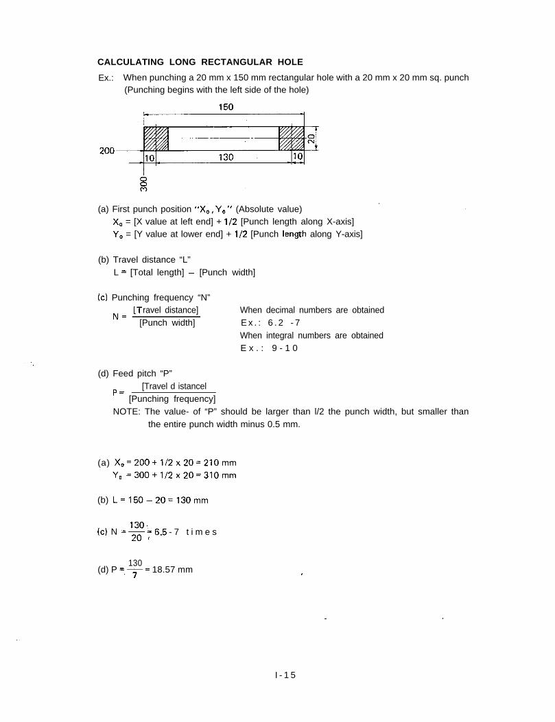
CALCULATING LONG RECTANGULAR HOLE
Ex.: When punching a 20 mm x 150 mm rectangular hole with a 20 mm x 20 mm sq. punch(Punching begins with the left side of the hole)
150
.(a) First punch position “X0, Y,,” (Absolute value)
X, = [X value at left end] + l/2 [Punch length along X-axis]Y, = [Y value at lower end] + l/2 [Punch length along Y-axis]
(b) Travel distance “L”L = [Total length] - [Punch width]
(c) Punching frequency “N”
NC [T ravel distance][Punch width]
When decimal numbers are obtainedE x . : 6 . 2 - 7When integral numbers are obtainedE x . : 9 - 1 0
(d) Feed pitch “P”[Travel d istancel
’ = [Punching frequency]NOTE: The value- of “P” should be larger than l/2 the punch width, but smaller than
the entire punch width minus 0.5 mm.
(a) X, =200+1/2x20=210mmY, =300+1/2x20=310mm
(b) L=l50-20=130mm
(c) N =g;6.5 - 7 t i m e sI
130(d) P =,7= 18.57 mm
I
I - 1 5
Therefore the program is:G90 X210. Y310. T3 (20mmx20mmsq.)G91 X 18.57
-.,,. - ’
J -’
X 18.57X 18.57X 18.57X 18.57
- X 18.57X 18.57
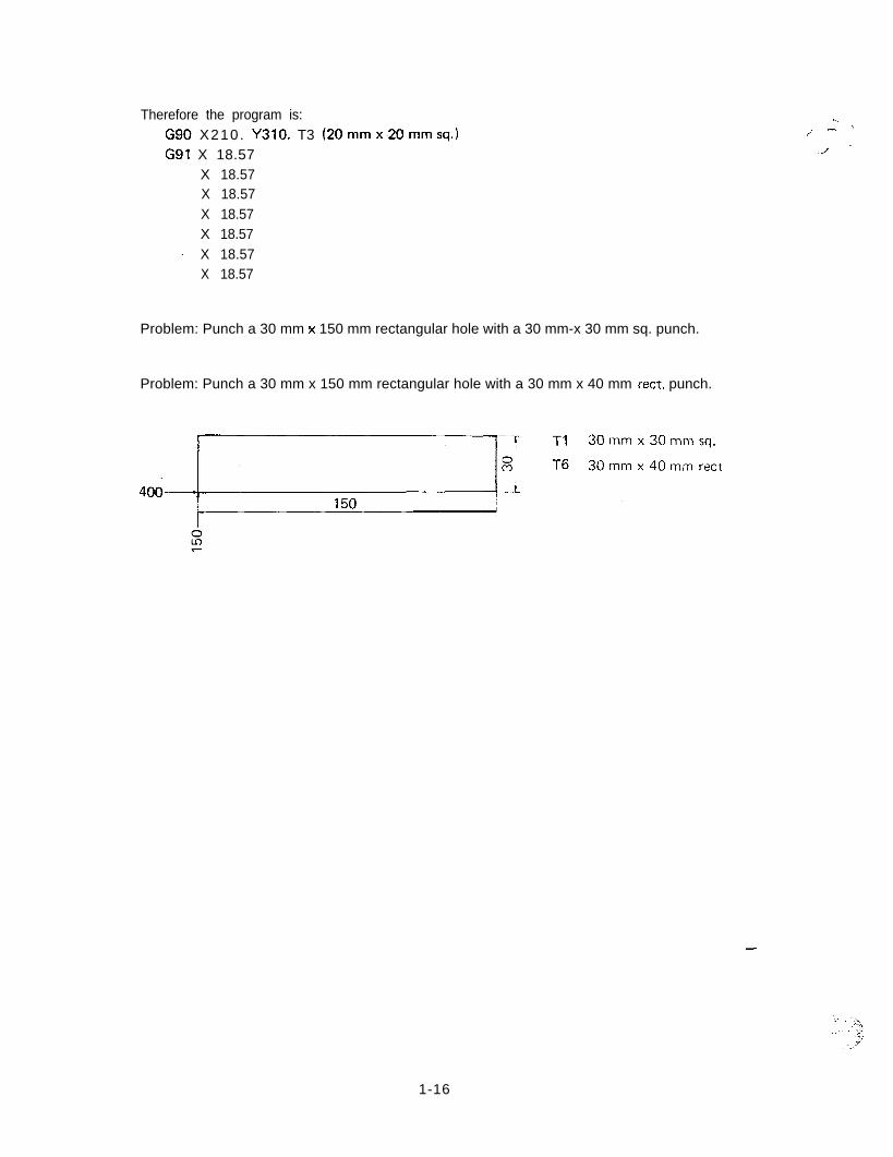
Problem: Punch a 30 mm x 150 mm rectangular hole with a 30 mm-x 30 mm sq. punch.
Problem: Punch a 30 mm x 150 mm rectangular hole with a 30 mm x 40 mm rect. punch.
-
1-16
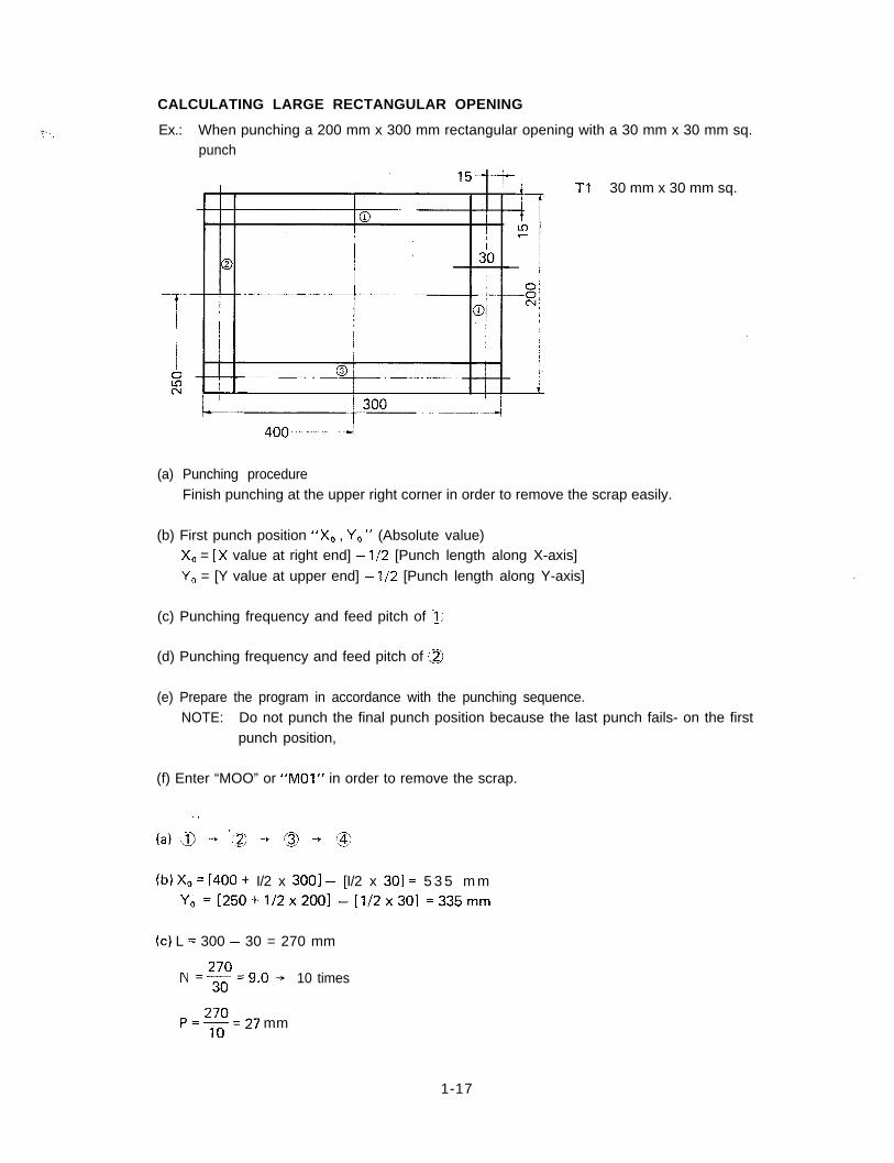
CALCULATING LARGE RECTANGULAR OPENING
Ex.: When punching a 200 mm x 300 mm rectangular opening with a 30 mm x 30 mm sq.punch
Tl 30 mm x 30 mm sq.
(a) Punching procedureFinish punching at the upper right corner in order to remove the scrap easily.
(b) First punch position “X,, , Y,” (Absolute value)X, = [X value at right end] - l/2 [Punch length along X-axis]Y, = [Y value at upper end] - l/2 [Punch length along Y-axis]
(c) Punching frequency and feed pitch of -1,’
(d) Punching frequency and feed pitch of ,a
(e) Prepare the program in accordance with the punching sequence.NOTE: Do not punch the final punch position because the last punch fails- on the first
punch position,
(f) Enter “MOO” or “MOI” in order to remove the scrap.
(b) X0 = [400 + I/2 x 3001 - [I/2 x 301 = 5 3 5 m mY, =[250+1/2x200] -[1/2x30] =335mm
(cl L = 300 - 30 = 270 mm
N =g=g.() -+ 10 times
P=+=27 mm
1-17
(d) L=200-30=170mm
N170
=x= 5.6 + 6 times
170p z---z6 28.33 mm
Therefore the program is:
G90 X535. Y335. Tl (30 mm x 30 mm sq.)G91 X - 2 7 . (IO times)
Y-28.33 (6 t imes)X27. (IO times)
Y28.33 (5 times)
MOO
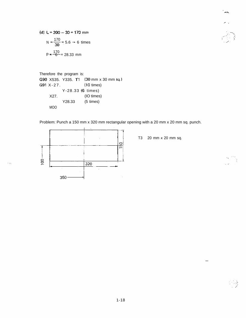
Problem: Punch a 150 mm x 320 mm rectangular opening with a 20 mm x 20 mm sq. punch.
T3 20 mm x 20 mm sq.
-
1-18
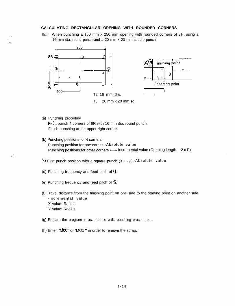
CALCULATING RECTANGULAR OPENING WITH ROUNDED CORNERS
/. Ex.: When punching a 150 mm x 250 mm opening with rounded corners of 8R, using a16 mm dia. round punch and a 20 mm x 20 mm square punch-. .,
250h -I
+ (ij
;- - - t
tf ‘
o--. _-- sa--
0a
0 -I7 i
400T2 16 mm dia.
T3 20 mm x 20 mm sq.
’ 8y - - + 8 + -
( Starting point
It
(a) Punching procedureFirst, punch 4 corners of 8R with 16 mm dia. round punch.Finish punching at the upper right corner.
(b) Punching positions for 4 corners.Punching position for one corner -Absolute value
Punching positions for other corners - Incremental value (Opening length - 2 x R)
(c) First punch position with a square punch (X,, Y, ) -Absolute value
(d) Punching frequency and feed pitch of @
(e) Punching frequency and feed pitch of 0
(f) Travel distance from the finishing point on one side to the starting point on another side-Incremental valueX value: RadiusY value: Radius
(g) Prepare the program in accordance with. punching procedures.
(h) Enter “dO0” or “MO1 “ in order to remove the scrap.
1 - 1 9
(a) 4 corners and then @ --f @ + @ + @
(b) Absolute value (upper right corner)X=[400+1/2x250] -8=517mmY = [300 + l/2 x 1501 - 8 = 367 mmIncremental valueX = 250 - [2 x 81 = 234 mmY=150- [2x81 =134mm
(c) Position of the first square punchingX0 =[400+1/2x250-81 -[1/2x20] =507mm
Y, = [300+1/2x 1501 - [1/2x201 =365mm
(d) L = [256-2xX] -20=214mm
214N =x = 10.7 - 1 1 t i m e s
214P=y= 19.45 mm
(e) L= [150-2x8] -20=114mm
114N = 20 = 5.7 ---6 times
114p=-=6
19 mm
(f) X = 8 mmY=8mm
Therefore the program is:G90 X517. Y367. T2 (16 mm dia.1
G91 X-234 .Y-l 34.
X234.GiO X567. 3 Y365. T3 (20 mm x 20 mm sq.)G91 X-19 .45 . (11 times) ’
X -8 . Y-8 .Y-l 9. (6 times)
X8. Y-8.x19.45 (11 times)
X8. Y8.Y19. (6 times)
MOO
-
I - 2 0
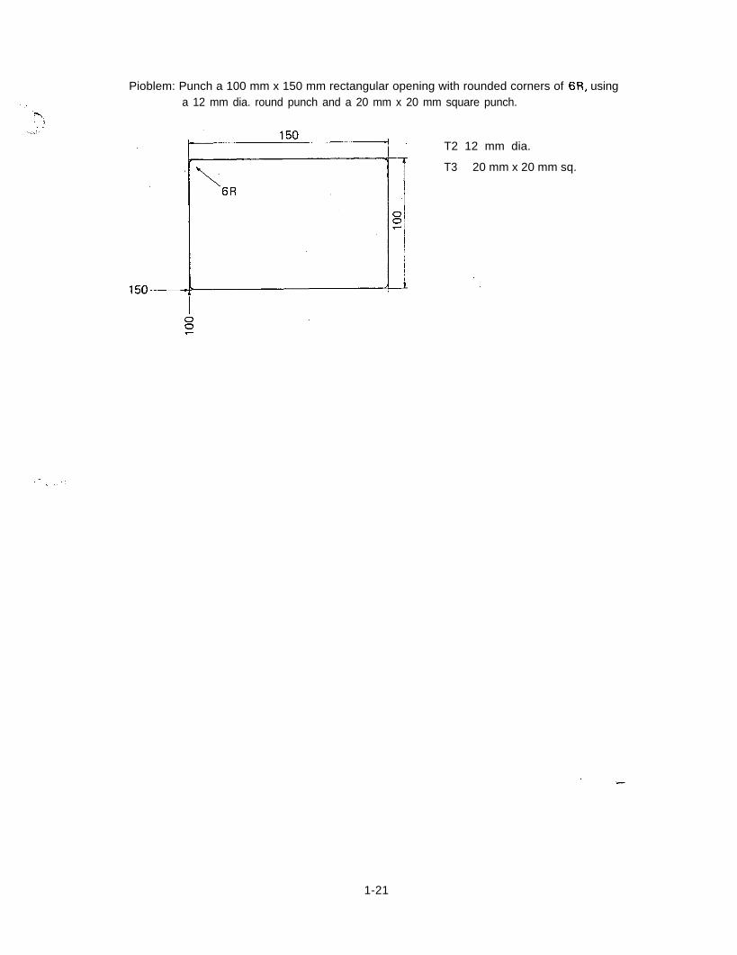
Pioblem: Punch a 100 mm x 150 mm rectangular opening with rounded corners of 6R, usinga 12 mm dia. round punch and a 20 mm x 20 mm square punch.
T2 12 mm dia.
T3 20 mm x 20 mm sq.
1-21
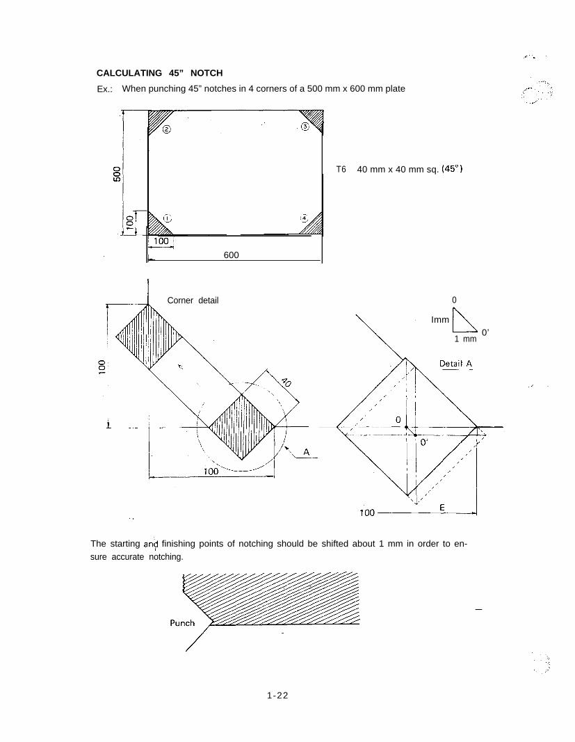
CALCULATING 45” NOTCH
Ex.: When punching 45” notches in 4 corners of a 500 mm x 600 mm plate
600
Corner detail
T6 40 mm x 40 mm sq. (45”)
0
\,
I Immn1 mm
0’
The starting an? finishing points of notching should be shifted about 1 mm in order to en-sure accurate notching.
-
1-22
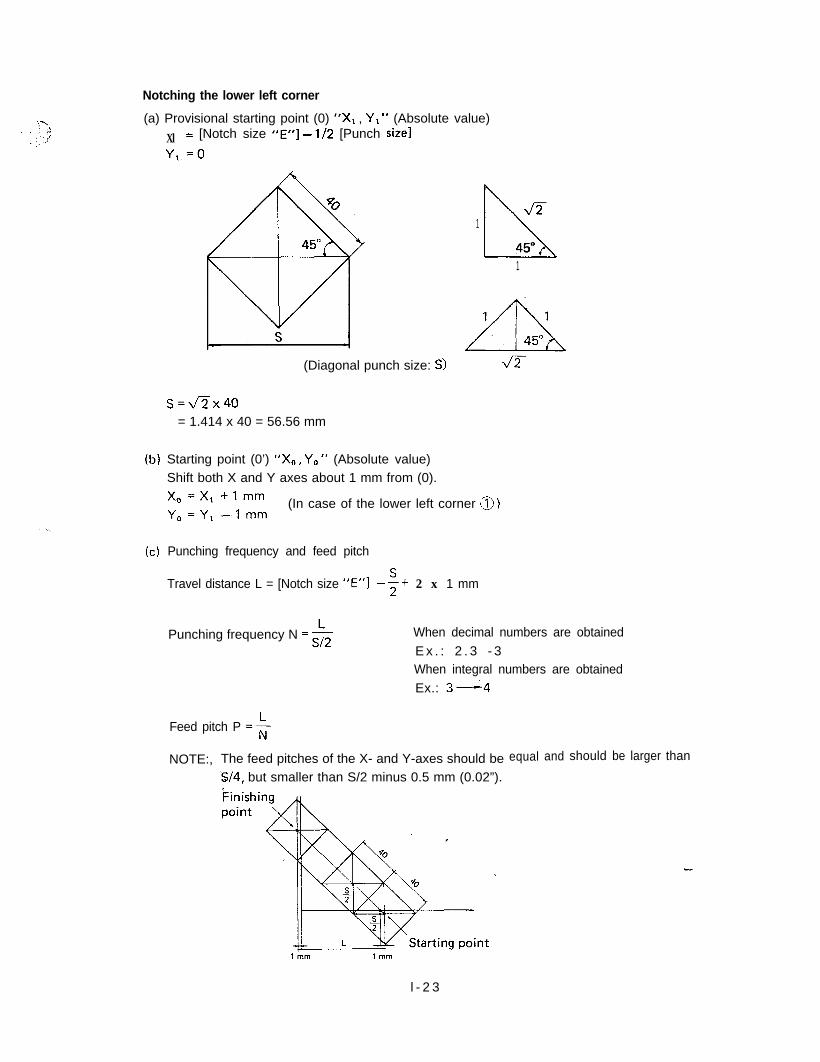
Notching the lower left corner
(a) Provisional starting point (0) “Xl , Y, ” (Absolute value)
Xl = [Notch size “E”] - l/2 [Punch Size]
Y,.=O
(b)
(cl
(Diagonal punch size: S>
s=fix40= 1.414 x 40 = 56.56 mm
&T1L45”
1
Starting point (0’) “X0, Y,,” (Absolute value)Shift both X and Y axes about 1 mm from (0).X,=X,-+lmm (In case of the lower left corner \B )Y,=Y,-lmm
Punching frequency and feed pitch
Travel distance L = [Notch size ","I -G+ 2 x 1 mm
Punching frequency N = $2 When decimal numbers are obtainedE x . : 2 . 3 - 3When integral numbers are obtainedEx.: 3-4
Feed pitch P =k
NOTE:, The feed pitches of the X- and Y-axes should beS/4, but smaller than S/2 minus 0.5 mm (0.02”).
equal and should be larger than
l - 2 3
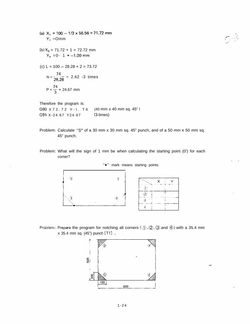
(a) X1 =lOO-1/2x56.56=71.72mm
Y1 =Omm
(b) X, = 71.72 + 1 = 72.72 mmY, =0- 1 =-l.OOmm
-./n, ‘.Ii ,..‘.,.’.,’ ’
(c) L = 100 - 28.28 +. 2 = 73.72
N =& = 2.62 -3 times
P =$= 24.67 mm
Therefore the program is:
G90 X 7 2 . 7 2 Y - l . T 6 (40 mm x 40 mm sq. 45” 1
G91 X -24 .67 Y24 .67 (3 times)
Problem: Calculate “5” of a 30 mm x 30 mm sq. 45” punch, and of a 50 mm x. 50 mm sq.45” punch.
Problem: What will the sign of 1 mm be when calculating the starting point (0’) for eachcorner?
. .I. “0” mark means starting points.
I
Problem:,Prepare the program for notching all corners (ix), a, 0 and @) with a 35.4 mmx 35.4 mm sq. (45”) punch [Tll . .
-
:
1 - 2 4
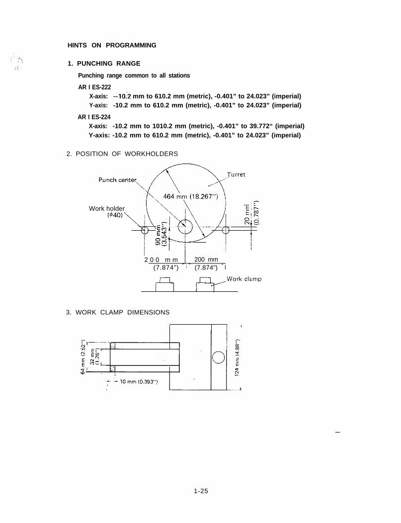
HINTS ON PROGRAMMING
1. PUNCHING RANGE
Punching range common to all stations
AR I ES-222X-axis: -lo:2 mm to 610.2 mm (metric), -0.401” to 24.023” (imperial)Y-axis: -10.2 mm to 610.2 mm (metric), -0.401” to 24.023” (imperial)
AR I ES-224X-axis: -10.2 mm to 1010.2 mm (metric), -0.401” to 39.772“ (imperial)Y-axis: -10.2 mm to 610.2 mm (metric), -0.401” to 24.023” (imperial)
2. POSITION OF WORKHOLDERS
Work holder
2 0 0 m m / 200 mm j(7.874”) - 1 - (7.874”) - I
3. WORK CLAMP DIMENSIONS
-
1-25
HINTS ON AUTO REPOSITIONING .
1. Repositioning travel distance ---as small as possibleARIES-222 [Maximum processing position (X value)] - 610 mm (24.015”)ARIES-224 [Maximum processing position (X value)] - 1010 mm (39.764”)
2. Clamp position ---as far apart as possibleConsider the following:l Dead zonel Worksheet sizel Notches
3. First processing area ----as large as possible
4. Reposition(a) Ensure the worksheet is under the work holders.(b) Ensure the clamps do not pass between the upper and lower turrets when the reposi-
tioning is done. YlOO.00 mm (min.)(c) Ensure the X-axis absolute value is greater than the repositioning travel distance. If
it is not greater than the repositioning travel distance, over-travel will occur.
5. Coordinate value after “G27” and “G25”Use dimensions as per diagram. Mode of G90 and G91 does not change.
6. Avoid changing tools immediately after repositioning to save processing time.
7. Processing area after auto repositioning (AR I ES-222)-10.2 mm (-0.401”) + repositioning travel distance 5 X 5 610.2 mm (24.023”) +repositioning travel distance.
Ex.: G27 X500. (X20.000)Processing area after auto repositioning = 489.8 5 X 5 1110.2 mm
(19.283” 5 X 2 44.023")NOTE: When the repositioning detector switch has been turned to ON, the repositioning
light will be lighted and a pause is made for confirmation before auto repositioningprovided the programmed Y-axis value is less than 95 mm (3.74”). In this case be
“sure, to check to ensure that there is no interference between the work holdersand work clamps before pressing start button.
11_0d2$gT y2;;g?!7 489.80 mm,I*, (I 9 . 2 8 3 ” ) ll;:
,.c -.:I ‘.
.i
.2c
.0;13m;l,I
Travel area Travel area1
\ \4-l rl m fy _
Before repositioning After G25X500. (X20.000) repositioning‘..
l - 2 6
BASIC SOFTWARE
G72 - DESIGNATION OF PATTERN ORIGIN
!cRN-! pR3 G72 X (X POSITION)i lSHlFTl /.-.-j ‘._--..G, [PATTRN ORIGIN] .Y (Y POSITION);
G90 G72 X YG91 G72 X-Y-This code is used to designate the pattern origin.
.-Ex.: G90 G72 X500. Y300.The pattern origin can be entered both as an absolute value and as an incremental value.“G72” merely selects a coordinate; neither positioning nor punching is performed.Never enter the M or T code in a block with “G72”.For example, never enter:
G90 G72 X300. Y200. T2G91 G72 X150. Y250. MOO
If an incremental value of X and Y is given after a pattern command, the value must referto the final pattern point.
-
2 - l
G28 - LINE AT ANGLE(‘-..-.---; r&y
PAATRN : !G2* I (PITCH) J (ANGLE)
ISHIFT)’ ;~.. ‘j [LINE ANGLE1 K. (NO. HOLE) T (TOOL NO.);
Starting from either the current position or from a point designated by “G72”, “n” holesare punched with a pitch of “d” at an angle of “0“ to the X-axis.
I: Pitch “+ d” When “d:’ is negative, the punching is performed in the opposite direc-tion from that of positive “d”.
J : Angle ‘9. 0 ” Counterclockwise - positiveI 3
Clockwise - negative Pattern origin ! f\ : ?’ +o‘i,
K: Number of holes “n” (excluding the point of the pattern origin)
NOTE: “d” and “0” are given as follows:
d 200 mm- 200. (d5” - 5.)e 45”30’ -------45.5
e 45” - 45.
Example: 6 holes - 10 mm dia/
.B I:L F i n a l
/’I
, L “ Pattern origin
E 10 mm dia: T2
G90 G!? X 3 0 0 . Y200.
G28 125. J30. K6 T2
punch
point
When punching the same hole at the pattern origin (X300., Y200. ,), omit “G72” and enter“T2” in the upper instruction block.
When “125.” becomes “I-25.“, punching is performed in the direction of 180” symmetry
(210” 1.,
. .
2 - 2
Problem:
4 holes - 10 mm dia. 10 mm dia.: T2
Problem:
7 holes - 5 mm dia.
b ij’ -a.
5 mm dia.: T8
2 - 3
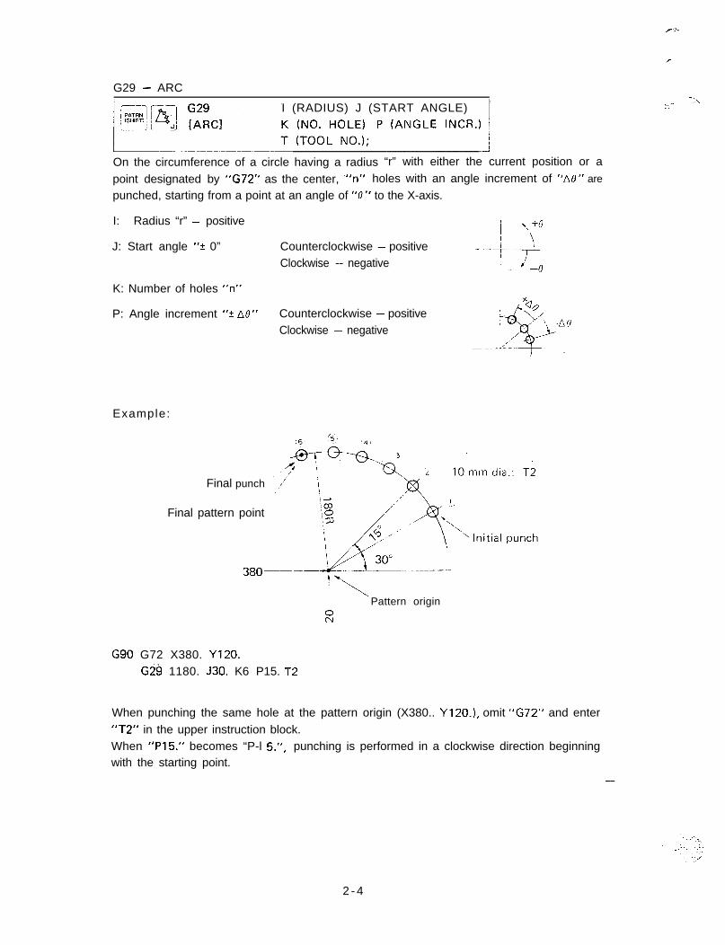
G29 - ARC
I (RADIUS) J (START ANGLE)
On the circumference of a circle having a radius “r” with either the current position or a
point designated by “G72” as the center, +‘n” holes with an angle increment of “AO” are
punched, starting from a point at an angle of “0” to the X-axis.
I: Radius “r” - positive
J: Start angle “? 0”
K: Number of holes “n”
Counterclockwise - positiveClockwise - negative
P: Angle increment “+ Atl” Counterclockwise - positiveClockwise - negative
Example:
Final punch
Final pattern point
380-
G90 G72 X380. Y120.Gi!iI 1180. J30. K6 P15. ,,zl-9
I.1Pattern origin
2
When punching the same hole at the pattern origin (X380.. Y120.1, omit “G72” and enter“T2” in the upper instruction block.When “P15.” becomes “P-l 5.“, punching is performed in a clockwise direction beginningwith the starting point.
,^ -\I.
-
2 - 4
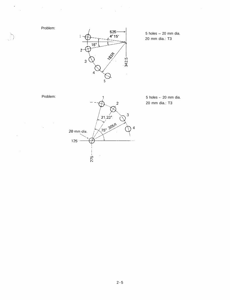
Problem:
Problem:
1
2
5
5 holes - 20 mm dia.20 mm dia.: T3
5 holes - 20 mm dia.
20 mm dia.: T3
2 - 5
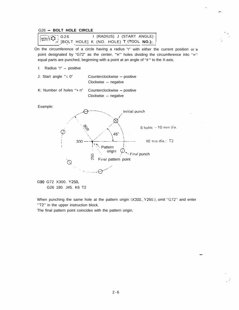
G26 - BOLT HOLE CIRCLE . ‘.i,;; @’ G 2 6 I (RADIUS) J (START ANGLE) .’! ,SrnFTl !
-.H_! [BOLT HOLE] K (NO. HOLE) T, (TOO!. NO.); ,.’2’
- - -On the circumference of a circle having a radius “r” with either the current position or‘s
point designated by “G72” as the center, “n” holes dividing the circumference into “n”equal parts are punched, beginning with a point at an angle of “0” to the X-axis.
I: Radius “r” - positive
J: Start angle “+_ 0” Counterclockwise - positiveClockwise - negative
K: Number of holes “f n” Counterclockwise - positiveClockwise - negative
Example:
\i \.h,’ > \ Pattern/ \
%\A ’
origi
‘b
n‘Final punch/-
2 Finai pattern point
G90 G72 X300. Y250.G26 180. J45. K6 T2
When punching the same hole at the pattern origin (X300., Y250.1, omit “G72” and enter“T2” in the upper instruction block.The final pattern point coincides with the pattern origin.
-
2 - 6
”
,:._
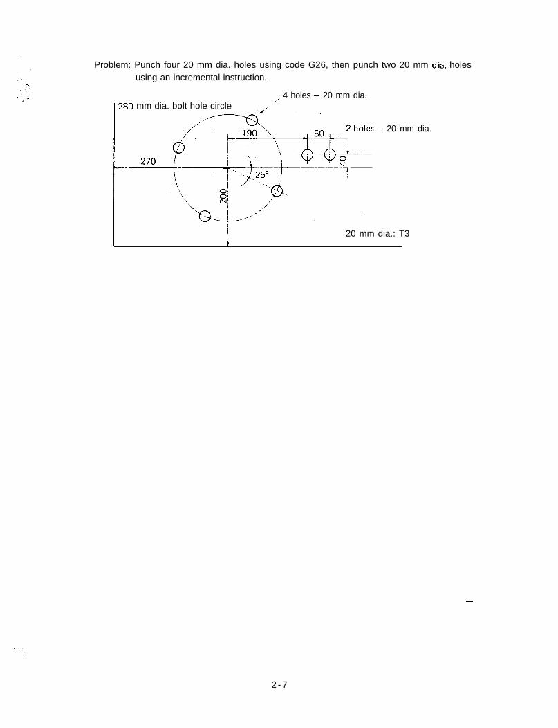
Problem: Punch four 20 mm dia. holes using code G26, then punch two 20 mm dia. holesusing an incremental instruction.
mm dia. bolt hole circle,,, 4 holes - 20 mm dia.
/
20 mm dia.
I 20 mm dia.: T3I i
-
2 - 7
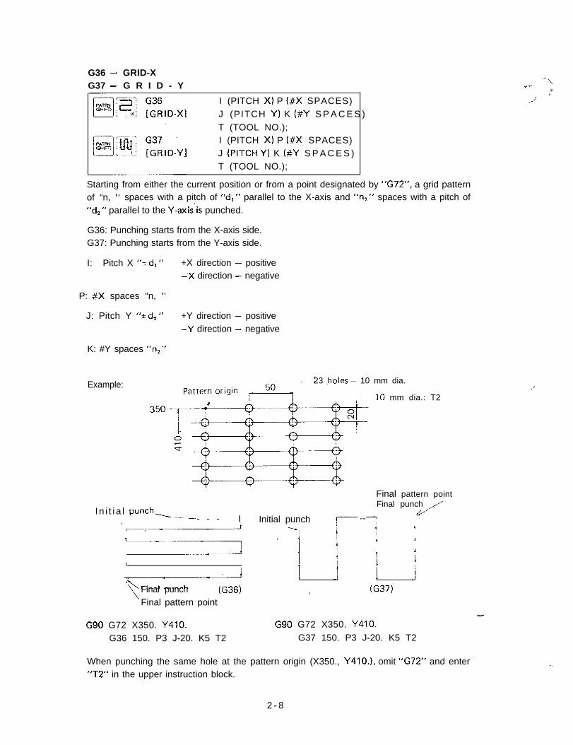
G36 - GRID-X --\G37 - G R I D - Y -,ir’--
..“’I (PITCH X) P (#X SPACES)J (PITCH Y) K (#Y S P A C E S )T (TOOL NO.);
.-’
I (PITCH X) P (#X SPACES)J (PITCH Y) K (#Y S P A C E S )T (TOOL NO.);
Starting from either the current position or from a point designated by “G72”, a grid patternof “n, ” spaces with a pitch of “dl ” parallel to the X-axis and “n2 “ spaces with a pitch of“d2 ” parallel to the Y-axisis punched.
G36: Punching starts from the X-axis side.G37: Punching starts from the Y-axis side.
I: Pitch X “+ d, ” +X direction - positive-‘X direction - negative
P: #X spaces “n, ”
J: Pitch Y “+ d, ” +Y direction - positive-.Y direction - negative
K: #Y spaces “n2 “
Example: 23 .holes - 10 mm dia.
IO mm dia.: T2
Final pattern point
I n i t i a l punch,_ _Final punch ,,/
//_- - - _ I Initial punch f-- --TI
_-i --sI ! r fL---
i17\ Final punch (G36l
Final pattern point
I L,i ;
, (G37)
G90 G72 X350. Y410. G90 G72 X350. Y410.
G36 150. P3 J-20. K5 T2 G37 150. P3 J-20. K5 T2
-
When punching the same hole at the pattern origin (X350., Y410.1, omit “G72” and enter“T2” in the upper instruction block.
-.
2 - 8
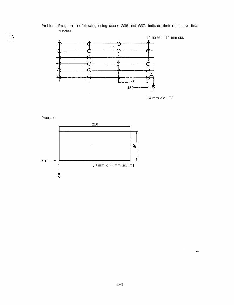
Problem: Program the following using codes G36 and G37. Indicate their respective finalpunches.
24 holes - 14 mm dia.
14 mm dia.: T3
Problem:
2101
50 mm x 50 mm sq.: T1
2-9
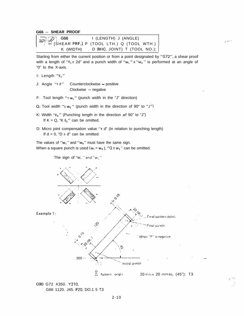
G66 - SHEAR PROOF< ----,/ PAWN j I (LENGTH) J (ANGLE)/ (S~IFTI i
i .~ M; [SHEAR PRF.] P (TOOL LTH.) Q (TOOL WTH.)..I -- ’
II K (WIDTH) D (MIC. JOINT) T (TOOL NO.); 1
Starting from either the current position or from a point designated by “G72”, a shear proofwith a length of ‘VI 2 2d” and a punch width of “wl ” x “w2” is performed at an angle of“0” to the X-axis.
I: Length “J1, ”
J: Angle “+ 8” Counterclockwise - positiveClockwise - negative .-
P: Tool length “k w1 ” (punch width in the “J” direction)
0: Tool width “? w2 ” (punch width in the direction of 90” to “J”)
K: Width “P1 ” (Punching length in the direction .of 90” to “J”)If K = Q, “K P, “ can be omitted.
D: Micro joint compensation value “? d” (in relation to punching length)If d = 0, “D + d” can be omitted.
The values of “wl “ and “w2 ” must have the same sign.When a square punch is used (w, = w2 ), “0 f wz ” can be omitted.
The sign of “w, ” and “w: ”
0
- Pattern originN 20 mm x 20 mm sq. (45”): T3
G90 G72 X350. Y210.G66 1120. J45. P20. DO.1 5 T3
. :\:‘
I,.,
2-10
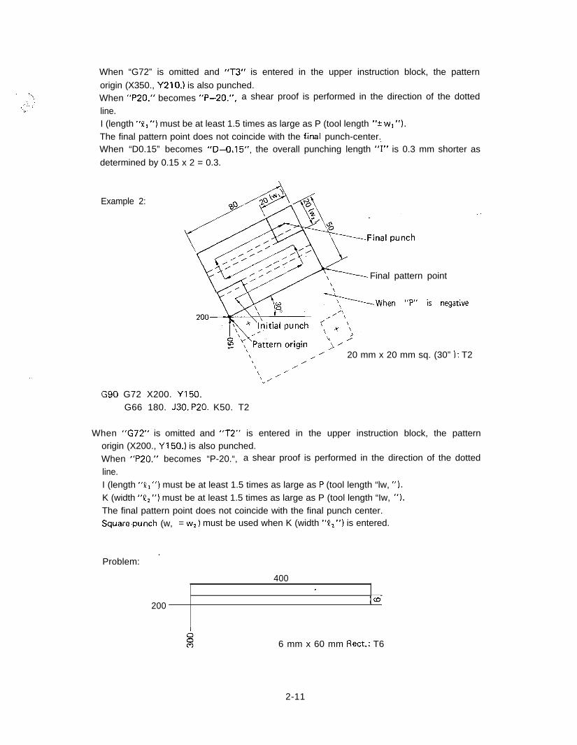
When “G72” is omitted and “T3” is entered in the upper instruction block, the pattern
origin (X350., Y210.) is also punched.When “P20.” becomes “P-20.“, a shear proof is performed in the direction of the dotted
line.I (length “Q1 “) must be at least 1.5 times as large as P (tool length “* w1 ‘I).The final pattern point does not coincide with the final punch-center.When “D0.15” becomes “D-0.15”, the overall punching length “I” is 0.3 mm shorter as
determined by 0.15 x 2 = 0.3.
Example 2:
Final pattern point
2-&:o, <yyWh’” “p“ is negative\ Y’\ // 20 mm x 20 mm sq. (30” ): T2
. .
G90 G72 X200. Y150.G66 180. J30. P20. K50. T2
\ /\ /’ /’‘_ ’
When “G72” is omitted and “T2” is entered in the upper instruction block, the patternorigin (X200., Y150.) is also punched.When “P20.” becomes “P-20.“, a shear proof is performed in the direction of the dotted
line.I (length “VI “) must be at least 1.5 times as large as P (tool length “lw, “).K (width “P2 “) must be at least 1.5 times as large as P (tool length “Iw, ‘I).The final pattern point does not coincide with the final punch center.Square,punch (w, = w2 ) must be used when K (width “P2 “) is entered.
Problem: ’
400,
200IW
6 mm x 60 mm Rect.: T6
2-11
G67 - SQUARE -,
H F!! I;ZJAREI
I (LENGTH Xl J (WIDTH Y) ‘-.- .:.L.’
P (TOOL LTH. X) Q (TOOL WTH. Yl ,T (TOOL NO.); MOO (STOP);- -
j
Starting from either the current position or from a point designated by “G72”, a rectangularopening with a length of “Ql” parallel to the X-axis and a length of “!&I parallel to the
Y-axis is punched, using a square punch with a width of “w”.
I: Opening length in the-X-axis direction “? Q, ” +X direction - positive-Y direction - negative
J: Opening length in the Y-axis direction “+ P, ” +Y direction - positive.-Y direction - negative
P: Tool length in the X-axis direction “w” (positive value only)
Q: Tool width in the Y-axis direction “w” (positive value only)
NOTE: As a square punch is normally used on programming G67 function, “Q” is oftenomitted.
Example:
P-
Pattern origin
240 560~i~Final pattern point
20IIi
-+---+ f1,
Initial punch,q+ i I
/8’ :
oi ej c, c-9
Final punch
!c 20 mm x 20 mm sq.: T3
G9tI G72 X560. Y370.G67 I-240. J-120. P20. T3MOO
When “G72” is omitted and “T3” is entered in the upper instruction block, the patternorigin (X560., Y370.) is also punched.When “G67” is fused, “MOO” or “MOl” should be entered in order to remove the scrap.
Both I and J (length X “? III “ and Y ‘9 Q, “1 must be at least three times as large as P (tool
length “w”).
2-12
.y,
.
Problem: 350
I200
1
z 30 mm x 30 mm sq.: T6
.’
2-13
G68 - NIBBLING ARC
~zi-~ i”] G68 I (RADIUS) J (START ANGLE)u-
i. -.;4, [NIBBLE ARC] K (MOV. ANGLE) P (TOOL DIA.): ,I’
.Q (NIB. PITCH) T (TOOL NO.): MOO (STOP);
On the circumference of a circle having a radius “r” with either the current position or a
point designated by “G72” as the center, a nibbling with a pitch of “d” is performed byusing a punch with a diameter of “4,” starting from a point at an angle of “0 1 ” to the X-axisand moving up to an incremental angle of “eZ “.
I: Radius “r” - positive value
J: Start angle “k 0, ” Counterclockwise - positive .-
Clockwise - negative
K: Moving angle in which nibbling occurs “2 0 2 ”Counterclockwise - positiveClockwise - negative
P: Tool diameter “f 4”Enter the positive value when nibbling the outer sideof the circle and the negative value when nibbling theinner side.
0: Nibbling pitch “d” - positive value onlyWorksheet thickness < d 2 6 mm (0.236”)
NOTE: Maximum worksheet thickness for nibbling: 3.2 mm (0.125”)
Example:
25 mm dia.:
Final pattern point
Final punch
,
- - - - - In i t ia l
, \
i
Pattern origin
T3
punch
G90 G72 X300. Y250. -G68 160. J30. KllO. P-25. Q6. T3
When “G72” is omitted and “T3” is entered in the upper instruction block, the patternorigin (X300., Y250.) is also punched.
“.
__”
-.
,’
2-14
When the value of “P” is zero, nibbling is performed on the arc with the radius “r”.Example:
When nibbling a worksheet with a thickness of more than 3.2 mm (0.125”), use code G29
(ARC) or G78 (PUNCHING ARC). .-
When the scrap remains inside, make “J” (start angle “k ‘0, “I 90” or 45” and enter “MOO”
or “MO1 ” in order to remove the scrap.
Problem: Program the following using NBL-A (G68) and SHP (G66).
-
20 mm dia.: T3
50 mm sq.: T6
A
8e
,
400
>
600
2-15
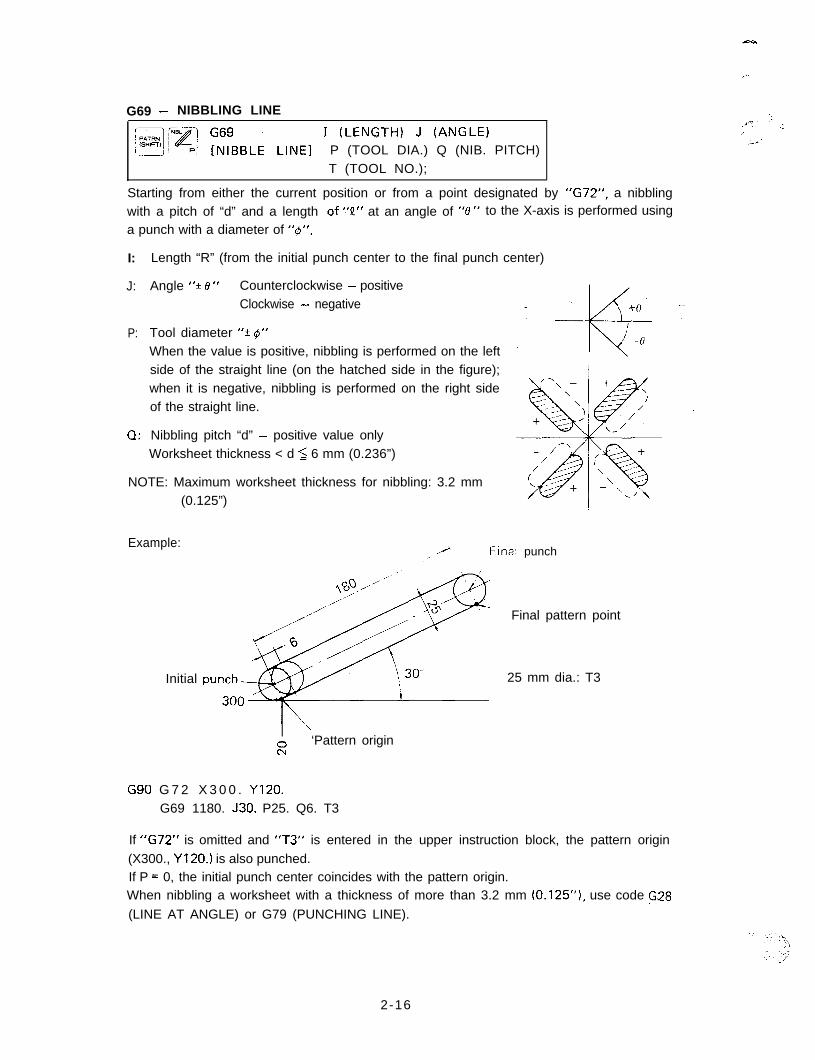
G69 - NIBBLING LINE ::
L&~ ;;yBBLE LINEl I (LENGTH) J (ANGLE).J_ - .-I,/
..-J PJ P (TOOL DIA.) Q (NIB. PITCH)T (TOOL NO.);
,._e’
Starting from either the current position or from a point designated by “G72”, a nibblingwith a pitch of “d” and a length .of “I?” at an angle of “0” to the X-axis is performed using
a punch with a diameter of “4”.
I:
J:
Length “R” (from the initial punch center to the final punch center)
Angle ‘*? e ” Counterclockwise - positiveClockwise - negative
P: Tool diameter “k 4”When the value is positive, nibbling is performed on the leftside of the straight line (on the hatched side in the figure);when it is negative, nibbling is performed on the right sideof the straight line.
0: Nibbling pitch “d” - positive value onlyWorksheet thickness < d 2 6 mm (0.236”)
NOTE: Maximum worksheet thickness for nibbling: 3.2 mm(0.125”)
Example:renal punch
Initial
. . ’
\
E‘Pattern origin
G90 G 7 2 X 3 0 0 . Yl20.G69 1180. J30. P25. Q6. T3
Final pattern point
25 mm dia.: T3
If “G72” is omitted and “T3” is entered in the upper instruction block, the pattern origin(X300., Yl20.) is also punched.If P = 0, the initial punch center coincides with the pattern origin.When nibbling a worksheet with a thickness of more than 3.2 mm (0.125”), use code G28
(LINE AT ANGLE) or G79 (PUNCHING LINE).
2-16
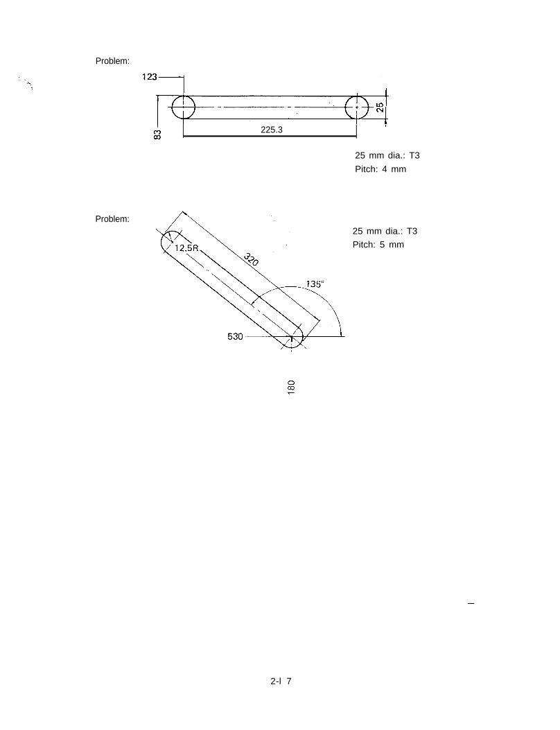
Problem:
Problem:
‘23>/I 225.3
rii2
25 mm dia.: T3
Pitch: 4 mm
25 mm dia.: T3
Pitch: 5 mm
-
2-l 7
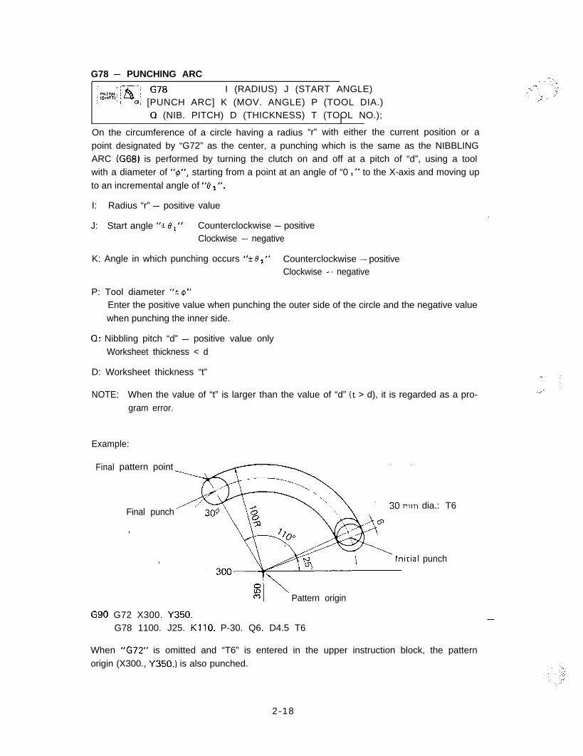
G78 - PUNCHING ARC/ -;p;%.%,‘~rg cm I (RADIUS) J (START ANGLE)! 1: .- 0; [PUNCH ARC] K (MOV. ANGLE) P (TOOL DIA.)
I0 (NIB. PITCH) D (THICKNESS) T (TOOL NO.);
On the circumference of a circle having a radius “r” with either the current position or a
point designated by “G72” as the center, a punching which is the same as the NIBBLINGARC (G68) is performed by turning the clutch on and off at a pitch of “d”, using a toolwith a diameter of “@“, starting from a point at an angle of “0 1 ” to the X-axis and moving upto an incremental angle of “0 2 “.
I: Radius “r” - positive value.-
J: Start angle “+_ 6’, “ Counterclockwise - positiveClockwise - negative
K: Angle in which punching occurs ‘9 e2 ” Counterclockwise - positiveClockwise - negative
P: Tool diameter “A 4”Enter the positive value when punching the outer side of the circle and the negative valuewhen punching the inner side.
0: Nibbling pitch “d” - positive value onlyWorksheet thickness < d
D: Worksheet thickness “t”
NOTE: When the value of “t” is larger than the value of “d” (t > d), it is regarded as a pro-gram error.
Example:
Final pattern point
Final punch
,
I
5:c-9 I’ Pattern origin
dia.: T6
punch
G90 G72 X300. Y350.G78 1100. J25. KllO. P-30. Q6. D4.5 T6
When “G72” is omitted and “T6” is entered in the upper instruction block, the patternorigin (X300., Y350.) is also punched.
-
2-18
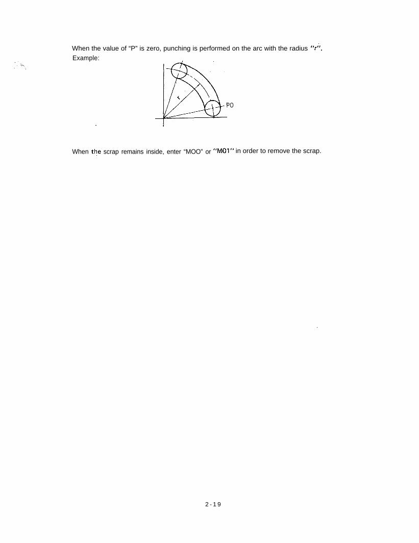
When the value of “P” is zero, punching is performed on the arc with the radius 7”.Example:
\
: B
iPO
When the scrap remains inside, enter “MOO” or “MOl” in order to remove the scrap.
2 - 1 9
G79 - PUNCHING LINE
. 1 HFJ YZNCH LINE] g ((Lrj$TT~.,‘T~~~;l~)); 1
Starting from either the current position or from a point designated by “G72”, a punchingwhich is the same as the NIBBLING LINE (G69) is performed by turning the clutch on andoff at a pitch of “d”, using a punch with a diameter of “@“, in the length of “e” at an angle
of “0 ” to the X-axis.
I: Length “Q” (from the initial punch center to the final punch center)
J: Angle “+ 0” Counterclockwise - positive .-Clockwise - negative
/
P: Tool diameter “? 4”When the value is positive, punching is performed on the left side of the straight line (onthe hatched side in the figure); when it is negative, punching is performed on the rightside of the straight line. Refer to the NIBBLING LINE (G69) on page 2-16.
Q: Nibbling pitch “d” - positive value onlyWorksheet thickness < d
D: Worksheet thickness “t”
NOTE: When “t” is larger than “d” (t > d), it is regarded as a program error.
?
Example:.
Final pattern po-int
$_( 1 Pattern origin
G90 G 7 2 X306. Y120.G79 1210. J25. P40. Q6. D4.5 T6
30 mm dia.: T6
If “G72” is omitted and “T6” is entered in the upper instruction block, the pattern origin(X300., Y120.) is also punched. -If P = 0, the initial punch center coincides with the pattern origin.
:..\
: I. .
-.;
2-20
PATTERN MEMORY AND PATTERN’ RECALL
When a pattern instructed by the codes G26, G28, G29, G36, G37, G66, G67, G68, G69,G78 or G79 is used repeatedly, the pattern can be memorized and recalled whenever re-quired. To memorize a pattern, enter the address letter “A” along with a one-digit numeral(from 1 to 5). To recall the pattern, enter the address letter “B” and the same one-digit
numeral as that was used by “A”.
Example:
300 -I750r IO mm dia.: T2
G90 G72 X300. Y250.Al G26 1125. J60. K6 T2 [Pattern memory]
G70 X400.G25 X350. _G72 X750.Bl [Pattern recall]
“AO” should always be entered at the front of the pattern command block; “BO” must beentered as a single block by itself. “AO” and “BO” are only used for the pattern memoryand recall. Memorization and recalling of a coordinate value are impossible with these.
2-21
Problem: Program the following with “AO”, “BO” and “G28”.
200’~ ’ T 34holesy lam,Ydia v--tps
’10mm dia.: T2
-..-.
,.* :
i,’
2-22 ,
G93 - OFFSET,- --- - _.-. -.
PATRNj OFFST Gg3 X (OFFSET X)
SHlFTi.~ .P [OFFSET] Y (OFFSET Y);-__-___
3
G90 G93 X Y I-. 1I
G91 G 9 3 X-Y-----I------------------------1
This.code designates the origin of the local coordinate system.
X and Y coordinate system: Basic coordinate system (Global coordinate system)
X’ and Y’ coordinate system: Local coordinate system
X” and Y” coordinate system: Local coordinate system
When designating the X’ and Y’ coordinate systemG90 G93 X50. Y75.
When designating the X” and Y” coordinate systemG90 G93 X200. Yl25. or, G91 G93 X150. Y50.
Method of designating point A(I 1 G90 X300. Y205. T 2(2) G90 G93 X50. Y75.
X250. Y130. T2(3) G90 G93 X50. Y75.
” G93 X200. Y125. (or G91 G93 X150. Y50.1X 1 0 0 . Y80. T 2
When changin$ from the local coordinate system to the global coordinate systemG90 G93 X0 YO
-
2-23

The G93 code is merely for establishing a coordinate system; it is not to be used for posi-tioning or punching. Do not enter “T” or “M” with “G93”.Example: G90 G93 X50. YlOO. T2
Program error
Basic format of a program using “G93”G92 x- -Y
G90 G93 X ----Y-X -..-.--Y- ~T
G50
. . i.,
:;::
2-24
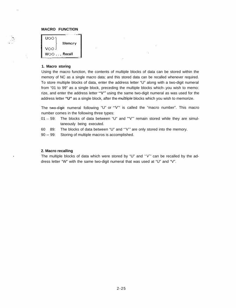
MACRO FUNCTION
1. Macro storingUsing the macro function, the contents of multiple blocks of data can be stored within thememory of NC as a single macro data; and this stored data can be recalled whenever required.To store multiple blocks of data, enter the address letter “U” along with a two-digit numeralfrom “01 to 99” as a single block, preceding the multiple blocks which-.you wish to memo:rize, and enter the address letter “V” using the same two-digit numeral as was used for theaddress letter “U” as a single block, after the mu‘ltiple blocks which you wish to memorize.
The twodigit numeral following “U” or “V” is called the “macro number”. This macro
number comes in the following three types:01 - 59: The blocks of data between “U” and “V” remain stored while they are simul-
taneously being executed.60 - 89: The blocks of data between “U” and “V” are only stored into the memory.90 - 99: Storing of multiple macros is accomplished.
.2. Macro recallingThe multiple blocks of data which were stored by “U” and “V” can be recalled by the ad-dress letter “W” with the same two-digit numeral that was used at “U” and “V”.
2-25
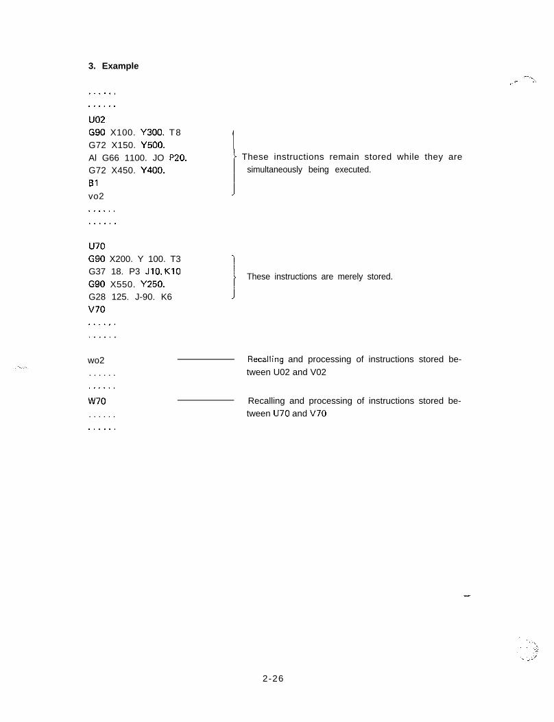
3. Example
. . . . . .
. . . . . .
u.02G90 X100. Y300. T8G72 X150. Y500.Al G66 1100. JO P20.G72 X450. Y400.Blvo2
.--:>.r,-
1t
These instructions remain stored while they aresimultaneously being executed.
J. . . . . ..-....
u70
G37 18. P3 JIO. KIOG90 X550. Y250.
G90 X200. Y 100. T3 i
I These instructions are merely stored.
G28 125. J-90. K6 J
v70............
wo2 Reca-Iling and processing of instructions stored be-
. . . . . . tween U02 and V02
. . . . . .
w70. . . . . .
Recalling and processing of instructions stored be-tween U70 and V70
. . . . . .
-
2-26
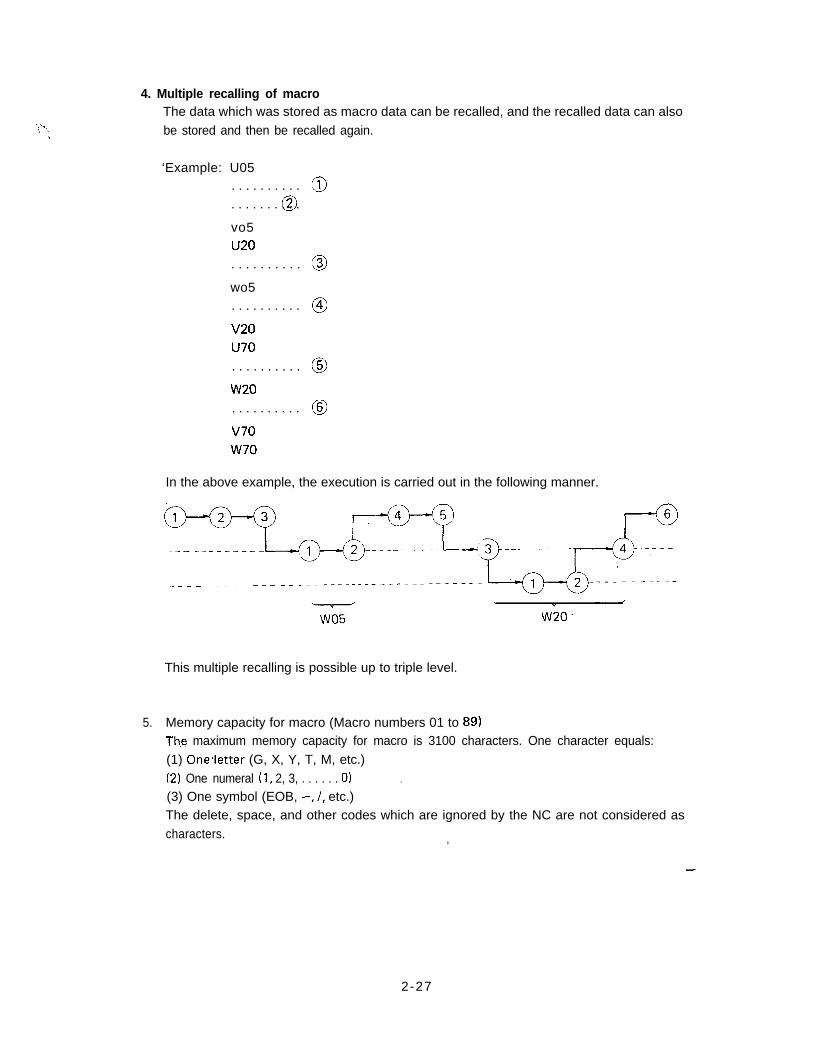
4. Multiple recalling of macroThe data which was stored as macro data can be recalled, and the recalled data can alsobe stored and then be recalled again.
‘Example: U05. . . . . . . . . . gl
@. . . . . . . . . .
vo5u20. . . . . . . . . . 3
wo5. . . . . . . . . . @
v20u70. . . . . . . . . . @
w20. . . . . . . . . . @
v70w70
In the above example, the execution is carried out in the following manner.
This multiple recalling is possible up to triple level.
5. Memory capacity for macro (Macro numbers 01 to 89)Th,e maximum memory capacity for macro is 3100 characters. One character equals:(1) OneSletter (G, X, Y, T, M, etc.)
.(2) One numeral (1, 2, 3, . . . . . . 0)(3) One symbol (EOB, -, /, etc.)The delete, space, and other codes which are ignored by the NC are not considered ascharacters. ,
-
2-27
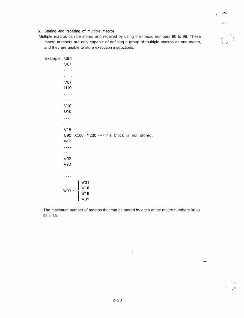
6. Storing and recalling of multiple macrosMultiple macros can be stored and recalled by using the macro numbers 90 to 99. These
macro numbers are only capable of defining a group of multiple macros as one macro,and they are unable to store execution instructions.
Example: iJ90UOI. . . .. . . .
VOlUIO. . . .. . . .
VI0u15. . . .. . . .
VI5G90 ‘X100. Y200. ----This block is not stored.uo2. . . .. . . .
. . . .
The maximum number of macros that can be stored by each of the macro numbers 90 to99 is 15.
,
2-28
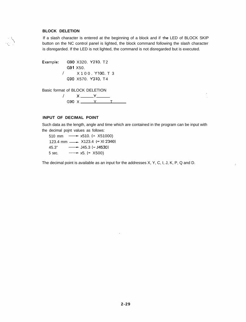
BLOCK DELETION
If a slash character is entered at the beginning of a block and if th.e LED of BLOCK SKIPbutton on the NC control panel is lighted, the block command following the slash characteris disregarded. If the LED is not lighted, the command is not disregarded but is executed.
Exampie: G90 X320. Y210. T2G91 X50.
I X 1 0 0 . YlOO. T 3G90 X570. Y310. T4
Basic format of BLOCK DELETION
I x-.-Y
G90 X Y T
INPUT OF DECIMAL POINT
Such data as the length, angle and time which are contained in the program can be input withthe decimal pojnt values as follows:
510 mm - x510. (= X51000)
123.4 mm - X123.4 (= Xl 2340)
45.3” - J45.3 (= J453015 sec. - x5. (= X500)
The decimal point is available as an input for the addresses X, Y, C, I, J, K, P, Q and D.
2-29
.*.il..,
MULTIPLE PART PUNCHING
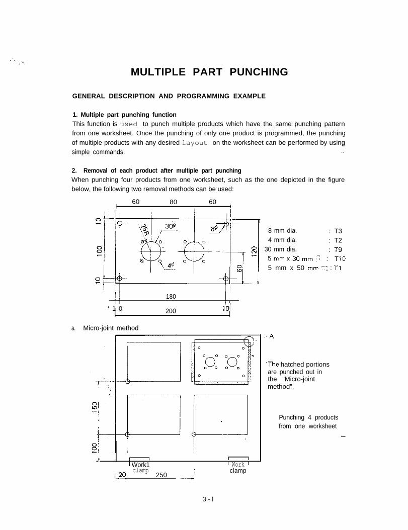
GENERAL DESCRIPTION AND PROGRAMMING EXAMPLE
1. Multiple part punching functionThis function is used to punch multiple products which have the same punching patternfrom one worksheet. Once the punching of only one product is programmed, the punchingof multiple products with any desired layout on the worksheet can be performed by usingsimple commands. .-
2. Removal of each product after multiple part punchingWhen punching four products from one worksheet, such as the one depicted in the figurebelow, the following two removal methods can be used:
60 80 60I I
j / 180I I /
‘ 1 0 200 1’0’
a. Micro-joint method
I I I I I
I Work1 1 Work 11 clamp
k20 / 250 d~mmAclamp
8 mm dia. : T34 mm dia. : T2
30 mm dia. : T95mmx30mm:: : TlO5 mm x 50 mm::: : Tl
.The hatched portionsare punched out inthe “Micro-jointmethod”.
Punching 4 productsfrom one worksheet
3 - l
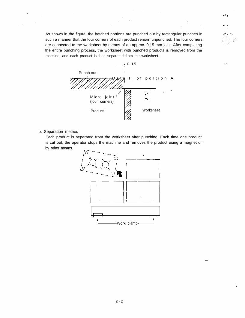
As shown in the figure, the hatched portions are punched out by rectangular punches in r-r -\xsuch a manner that the four corners of each product remain unpunched. The four cornersare connected to the worksheet by means of an approx. 0.15 mm joint. After completingthe entire punching process, the worksheet with punched products is removed from themachine, and each product is then separated from the worksheet.
)I 0 .15 . .
Punch outI -
I I
,
@ 1D e t a i l ; o f p o r t i o n A
Micro jo in t ; ’/ -Lnf-- - -’
‘ I(four corners) Oi
Product Worksheet
b. Separation methodEach product is separated from the worksheet after punching. Each time one productis cut out, the operator stops the machine and removes the product using a magnet orby other means.
1 I I I
tA
Work clamp-
:..:
3 - 2
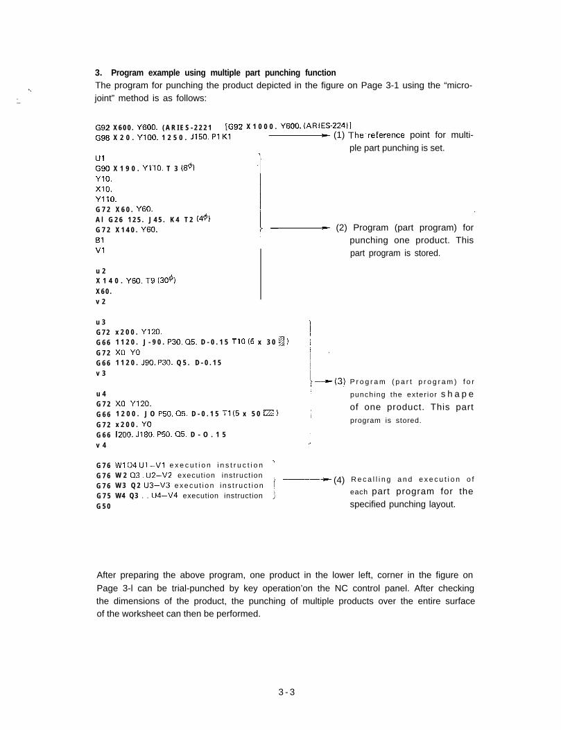
3. Program example using multiple part punching function
*\ The program for punching the product depicted in the figure on Page 3-1 using the “micro-
:.. joint” method is as follows:
G92 X 6 0 0 . Y600. ( A R I E S - 2 2 2 1 [G92 X 1 0 0 0 . Y600. (ARIES-22411
G98 X 2 0 . YlOO. 1 2 5 0 . J150. Pl Kl w (1) The.reference point for multi-ple part punching is set.
UlG90 X 1 9 0 . YllO. T 3 (89)YlO.x10.YllO.G 7 2 X 6 0 . Y60.A l G 2 6 1 2 5 . J 4 5 . K 4 T 2 (44)G 7 2 X 1 4 0 . Y60.Bl
.-
* (2) Program (part program) forpunching one product. This
Vl
u 2X 1 4 0 . Y60. T9 (30%
X 6 0 .v 2
u 3G 7 2G 6 6G 7 2G 6 6v 3
u 4G 7 2G 6 6G 7 2G 6 6v 4
G 7 6G 7 6G 7 6G 7 5G 5 0
x 2 0 0 . Y120.1 1 2 0 . J - 9 0 . P30. 05. D - 0 . 1 5 TlO (5 x 3 0 g ) jx0 YO1 1 2 0 . J90. P30. Q 5 . D - 0 . 1 5
x0 Y120.1 2 0 0 . J O P50. 05. D - 0 . 1 5 Tl (5 x 5 0 FZZ )
x 2 0 0 . YO1200. JlBO. P50. 05. D - O . 1 5
J
Wl 04 Ul -Vl e x e c u t i o n i n s t r u c t i o n ’W 2 Q3, U2-V2 execut ion instruct ion __--W 3 Q 2 U3-V3 e xecu t i on i ns t r uc t i onW4 Q3 . . U4-V4 execution instruction
- (4)
part program is stored.
P r o g r a m ( p a r t p r o g r a m ) f o r
punching the exter ior s h a p eof one product. This partprogram is stored.
R e c a l l i n g a n d e x e c u t i o n o f
each part program for thespecified punching layout.
After preparing the above program, one product in the lower left, corner in the figure on
Page 3-l can be trial-punched by key operation’on the NC control panel. After checkingthe dimensions of the product, the punching of multiple products over the entire surfaceof the worksheet can then be performed.
3 - 3
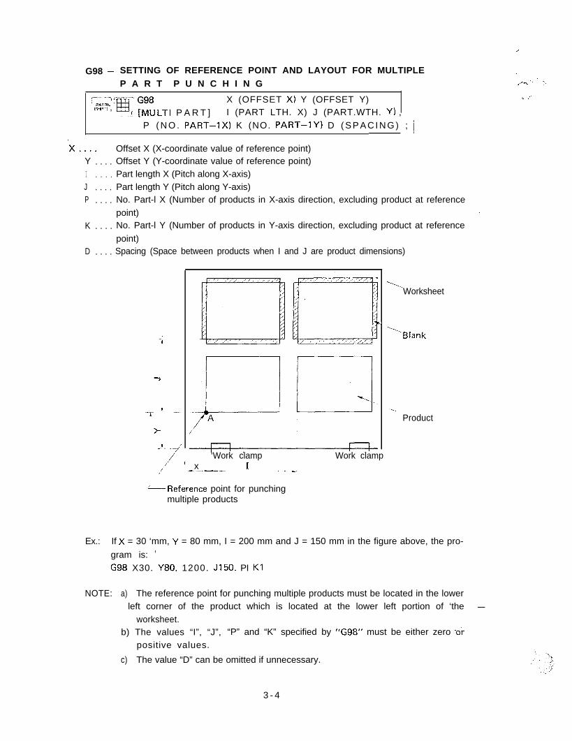
G98 - SETTING OF REFERENCE POINT AND LAYOUT FOR MULTIPLE :P A R T P U N C H I N G
-.;-. ‘. :,
~.._ -~ r...-~.-’ PATeN :
PA’ ;::LTl P A R T ]X (OFFSET X) Y (OFFSET Y) I. ,I’
ISHIFT, , i I (PART LTH. X) J (PART.WTH. Y) ,P ( N O . PART-lx) K (NO. PART-1Y) D ( S P A C I N G ) ; j
.x.... Offset X (X-coordinate value of reference point)Y . . . . Offset Y (Y-coordinate value of reference point)I . . . . Part length X (Pitch along X-axis)J . . . . Part length Y (Pitch along Y-axis)P . . . . No. Part-l X (Number of products in X-axis direction, excluding product at reference
point) .-
K . . . . No. Part-l Y (Number of products in Y-axis direction, excluding product at reference
point)D . . . . Spacing (Space between products when I and J are product dimensions)
-;
7
,.--r --..
>
-!-.. >/!
I.
‘...Worksheet
\Blank
.L..Product
/ ‘Work clamp Work clampi -.~-_-- 1’ x _ _ _,/
L__Reference point for punchingmultiple products
Ex.: If X = 30 ‘mm, Y = 80 mm, I = 200 mm and J = 150 mm in the figure above, the pro-
gram is: ’G98 X30. Y80. 1200. J150. PI Kl
NOTE: a) The reference point for punching multiple products must be located in the lowerleft corner of the product which is located at the lower left portion of ‘the -
worksheet.b) The values “I”, “J”, “P” and “K” specified by “G98” must be either zero ,o;
positive values.
c) The value “D” can be omitted if unnecessary.
3 - 4
Inclusion and priority relations between G98 and G931. The X- and Y-coordinates specified by “G98” are determined by the coordinate system
which is set by “G92”.2. The coordinate system set by “G98”, once specified, cannot be cancelled except by using
the subsequent commands of “G98” or “G50”.3. The X- and Y-coordinates specified by “G93” are determined by the coordinate system
which is set by “G98”..4. ’“G93” which is specified prior to the setting of “G98” will remain effective even after
“G98”. The values obtained by adding the X and Y values of “G98” and the X and Yvalues of “G93”, respectively, will determine the origin of this.program.
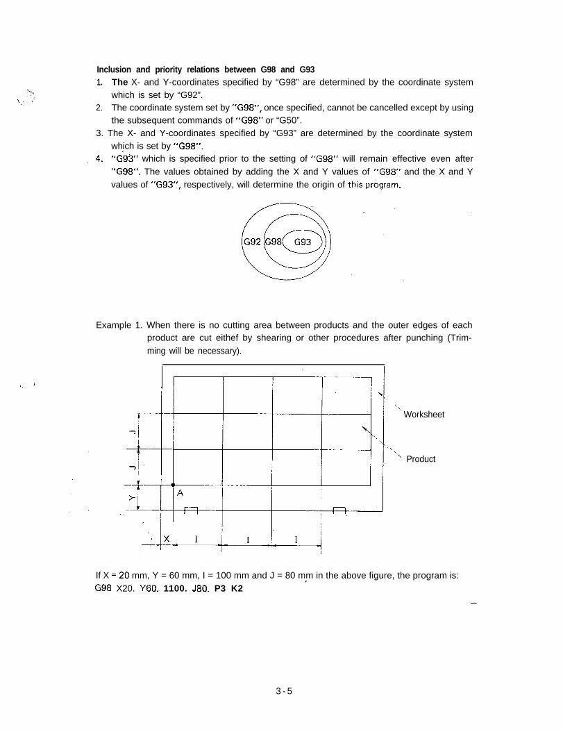
Example 1. When there is no cutting area between products and the outer edges of eachproduct are cut eithef by shearing or other procedures after punching (Trim-ming will be necessary).
‘l.
Worksheet
_\‘\ Product
If X =20 mm, Y = 60 mm, I = 100 mm and J = 80 mm in the above figure, the program is:IG98 X20. Y60. 1100. J80. P3 K2
-
3 - 5
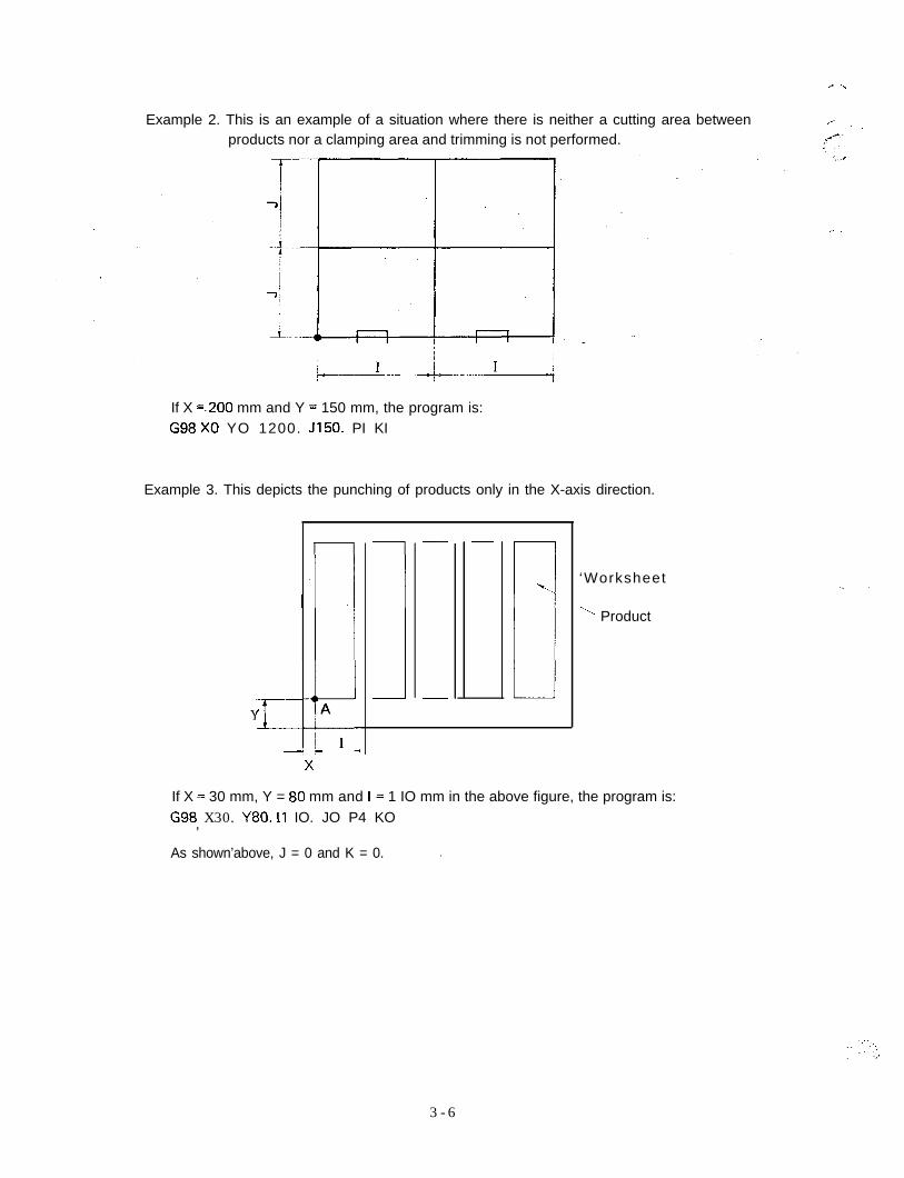
Example 2. This is an example of a situation where there is neither a cutting area between /- ., _products nor a clamping area and trimming is not performed.
If X =.200 mm and Y = 150 mm, the program is:G98 X0 YO 1200. JI50. PI KI
Example 3. This depicts the punching of products only in the X-axis direction.
YII
-LA
IC
b-..
i
‘Worksheet
‘*_ Product
If X = 30 mm, Y = 80 mm and I= 1 IO mm in the above figure, the program is:G98 X30. Y80. I1 IO. JO P4 KO,
As shown’above, J = 0 and K = 0. .
3 - 6
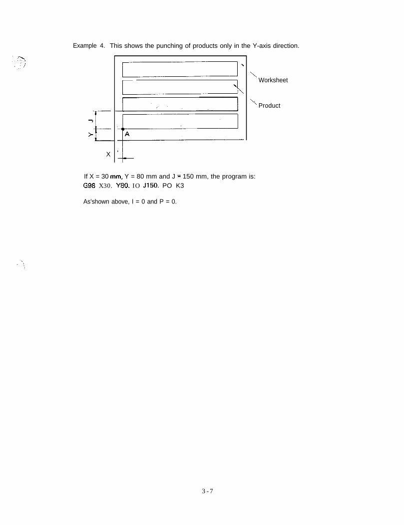
Example 4. This shows the punching of products only in the Y-axis direction.
1’ \Worksheet
X
\
‘\ Product
If X = 30 mm, Y = 80 mm and J = 150 mm, the program is:G98 X30. Y80. IO JI50. PO K3
As’shown above, I = 0 and P = 0.
3 - 7
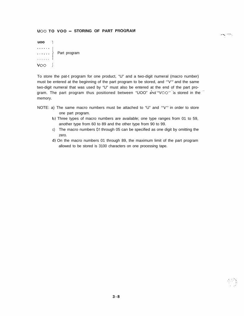
UOo TO VOO - STORING OF PART PKOC;RAM&, -.--.-
-uoo 1............ i Part program. . . . . . I
voo I
To store the pat-t program for one product, “U” and a two-digit numeral (macro number)must be entered at the beginning of the part program to be stored, and “V” and the sametwo-digit numeral that was used by “U” must also be entered at the end of the part pro-gram. The part program thus positioned between “UOO” ind “VOO”~‘is stored in the --memory.
NOTE: a) The same macro numbers must be attached to “U” and “V” in order to storeone part program.
b) Three types of macro numbers are available; one type ranges from 01 to 59,another type from 60 to 89 and the other type from 90 to 99.
c) The macro numbers 01 through 05 can be specified as one digit by omitting thezero.
d) On the macro numbers 01 through 89, the maximum limit of the part programallowed to be stored is 3100 characters on one processing tape.
3 - 8
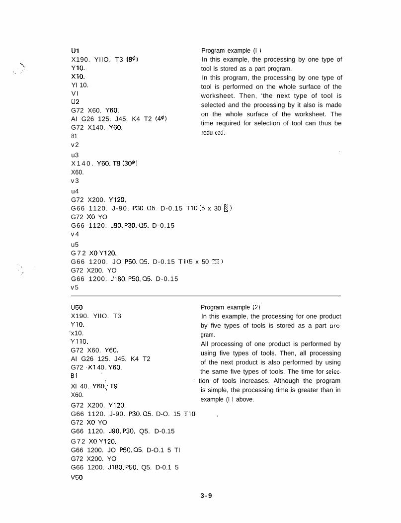
UIX190. YIIO. T3 (84)YlO.x10.YI 10.V I* *a
Program example (I 1In this example, the processing by one type oftool is stored as a part program.In this program, the processing by one type oftool is performed on the whole surface of theworksheet. Then, ‘the next type of tool is
UZ
G72 X60. Y60.AI G26 125. J45. K4 T2 (44)G72 X140. Y60.81v2
selected and the processing by it also is madeon the whole surface of the worksheet. Thetime required for selection of tool can thus beredu ted.
.-u3X 1 4 0 . Y60. T9 (304)X60.v 3
u4G72 X200. YI20.G66 1120. J-90. P30. 05. D-0.15 TIO (5 x 30 B,G72 X0 YOG66 1120. J90. P30. 05. D-0.15v 4
u5G 7 2 X0 YI20.G66 1200. JO P50. 05. D-0.15 Tl (5 x 50 :g 1G72 X200. YOG66 1200. J180. P50. 05. D-0.15v5
u50X190. YIIO. T3YIO.‘x10.YllO.G72 X60. Y60.AI G26 125. J45. K4 T2G72 ,X1 40. Y60.Bl ’
Xl 40. Y60:; T9X60.
Program example (2)In this example, the processing for one productby five types of tools is stored as a part pro-gram.All processing of one product is performed byusing five types of tools. Then, all processingof the next product is also performed by usingthe same five types of tools. The time for selec-
’ tion of tools increases. Although the programis simple, the processing time is greater than inexample (I ) above.
G72 X200. YI20.G66 1120. J-90. P30. 05. D-O. 15 TIOG72 X0 YO
,
G66 1120. J90. P30. Q5. D-0.15
G 7 2 X0 YI20.G66 1200. JO P50. 05. D-O.1 5 TIG72 X200. YOG66 1200. JI80. P50. Q5. D-0.1 5
v50
3 - 9
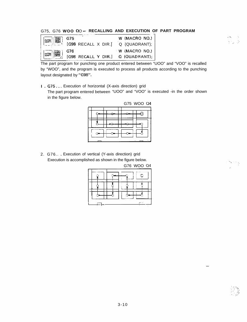
G75, G76 WOO 00 - RECALLING AND EXECUTION OF PART PROGRAM..% -. ‘..,. .:
[G98 RECALL X DIR.] Q (QUADRANT); _ ,. .,’
The part program for punching one product entered between “UOO” and “VOO” is recalledby “WOO”, and the program is executed to process all products according to the punching
layout designated by “Gg8”.
I . G75... Execution of horizontal (X-axis direction) gridThe part program entered between “UOO” and “VOO” is executed -in the order shown
in the figure below.
G75 WOO 04
2. G76.. . Execution of vertical (Y-axis direction) gridExecution is accomplished as shown in the figure below.
G76 WOO 04
-
3-10
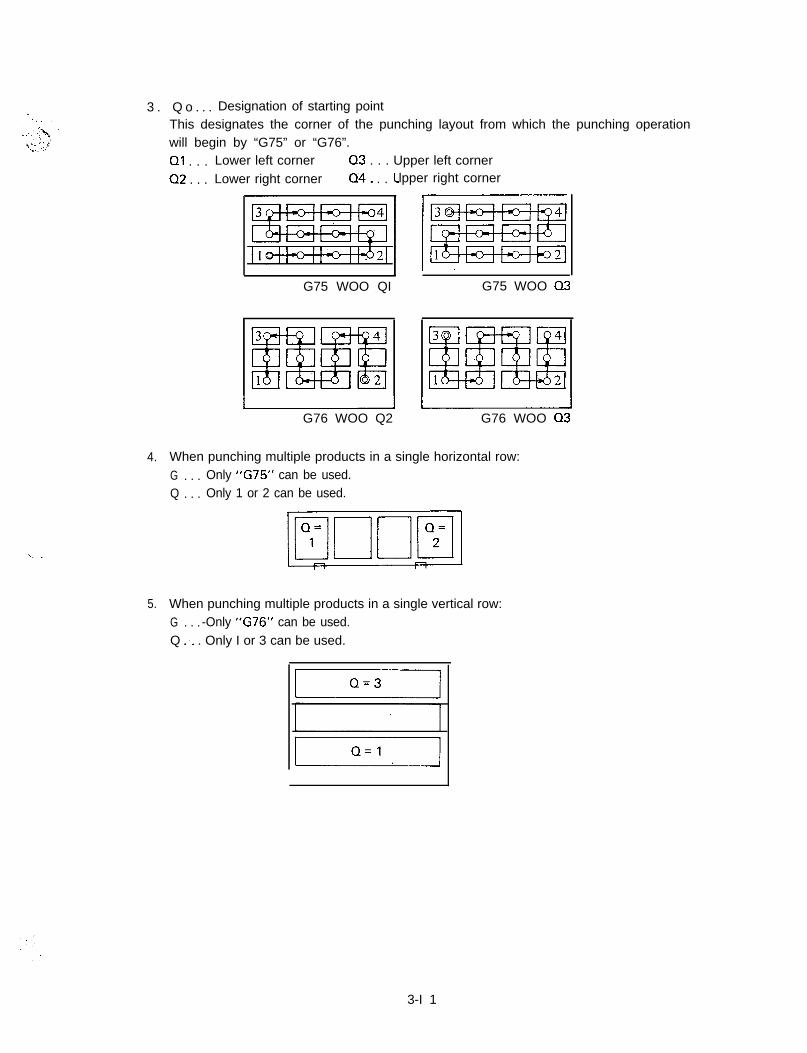
3 . Q o . . . Designation of starting pointThis designates the corner of the punching layout from which the punching operationwill begin by “G75” or “G76”.01 . . . Lower left corner 03 . . . Upper left corner
02 . . . Lower right corner 04. . . clpper right corner
G75 WOO QI G75 WOO 03
IIG76 WOO Q2 G76 WOO 03
4. When punching multiple products in a single horizontal row:G . . . Only “G75” can be used.Q . . . Only 1 or 2 can be used.
5. When punching multiple products in a single vertical row:G . . . -Only “G76” can be used.Q :. . Only I or 3 can be used.
3-I 1
6. Combination method of G75 and 01 to 04, or G76 and 01 to 04(a) Either “G75” or “G76” must be selected so that the distance of movement can be -. T.
minimized.-. 1,._I
(b) If the processing of a part program starts from the upper right corner (04) and endsat the upper left corner (Q3), the processing of the next part program should startat the upper left corner (Q3) in order to guarantee efficient movement.
(c) When cutting the outside shape in the process of punching multiple products, it isdesirable to start the punching at the upper portion of the worksheet and move lowerin sequence. For such a procedure, enter the command of: G75 WOO 04 or 3.
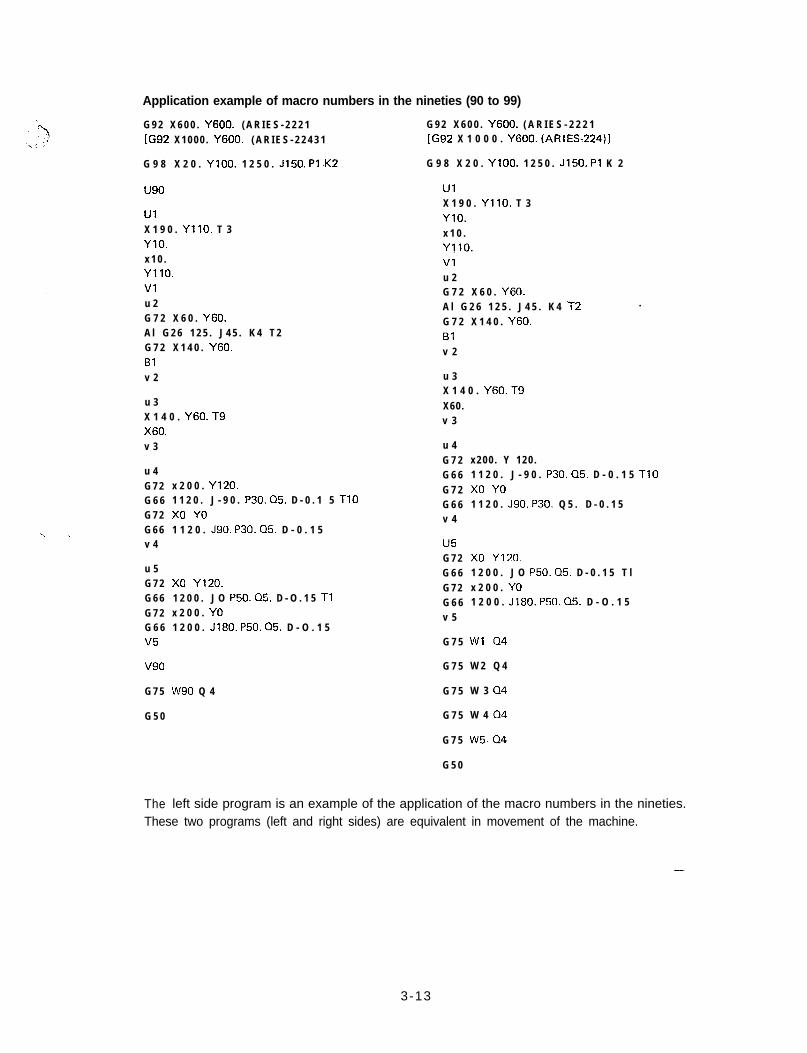
7. u90 to v90If the starting point designated by “0” is unchanged and either “G75” or “G76” is to --be used alone, it is possible to represent multiple sets of “UOO and VOO” by a single“UOO and VOO”. The macro number for this function is 90 to 99.NOTE: In each of the macro numbers 90 to 99, it is possible to store a maximum of I5
types of part programs.
-
3-12
.:
Application example of macro numbers in the nineties (90 to 99)
G 9 2 X 6 0 0 . Y600. ( A R I E S - 2 2 2 1[G92 X 1 0 0 0 . Y600. ( A R I E S - 2 2 4 3 1
G 9 8 X 2 0 . YlOO. 1 2 5 0 . J150. Pl -K2
u90
UlX 1 9 0 . YllO. T 3YlO.x 1 0 .YllO.Vlu 2G 7 2 X 6 0 . Y60.A l G 2 6 1 2 5 . J 4 5 . K 4 T 2G 7 2 X 1 4 0 . Y60.Blv 2
G 9 2 X 6 0 0 . Y600. ( A R I E S - 2 2 2 1[G92 X 1 0 0 0 . Y600. (ARIES-224)]
G 9 8 X 2 0 . YlOO. 1 2 5 0 . J150. Pl K 2
UlX 1 9 0 . YllO. T 3YlO.x 1 0 .YJlO.Vlu 2G 7 2 X 6 0 . Y60.A l G 2 6 1 2 5 . J 4 5 . K 4 t2 .
G 7 2 X 1 4 0 . Y60.Blv 2
u 3X 1 4 0 . Y60. T9
u 3 X60.X 1 4 0 . Y60. T9 v 3
v 3
u 4G 7 2G 6 6G 7 2
‘\ ~ G 6 6v 4
u 5G 7 2G 6 6G 7 2G 6 6v5
v90
G 7 5
G 5 0
The left side program is an example of the application of the macro numbers in the nineties.
x 2 0 0 . Y120.1 1 2 0 . J - 9 0 . P30. Q5. D - 0 . 1 5 TlOx0 YO1 1 2 0 . J90. P30. Q5. D - 0 . 1 5
x0 Yl20.1 2 0 0 . J O P50. Q5. D - O . 1 5 Tlx 2 0 0 . YO1 2 0 0 . Jl80. P50. Q5. D - O . 1 5
W90 Q 4
u 4G 7 2G 6 6G 7 2G 6 6v 4
u5G 7 2G 6 6G 7 2G 6 6v 5
G 7 5
G 7 5
G 7 5
G 7 5
G 7 5
G 5 0
x200 . Y 120 .1 1 2 0 . J - 9 0 . P30. 05. D - 0 . 1 5 TlOx0 YO1 1 2 0 . J90. P30. Q 5 . D - 0 . 1 5
x0 Y120.1 2 0 0 . J O P50. 05. D - 0 . 1 5 T lx 2 0 0 . YO1 2 0 0 . J180. P50. 05. D - O . 1 5
Wl 04
W 2 Q 4
W 3 04
W 4 04
W5.04
These two programs (left and right sides) are equivalent in movement of the machine.
-
3-13
TRIAL PUNCHING, POST-TRIAL PUNCHING, AND FULL PUNCHING ,”
In the conventional method of multiple part punching, punching must be accomplishedover the whole, surface of the worksheet, and then dimensional and accuracy checks must beconducted. Should the program contain any error, substantial worksheet and time losseswould result. However, in this multiple part punching function, selection between three typesof processing is available by key operation on the control panel, i.e. “trial punching for oneproduct”, “multiple punching for remaining products after trial punching” and “full punch-ing“.For details on this operation, refer to the “NC setup” in the OPERATOR’S MANUAL.
3 -14
CLAMP DEAD ZONE DIAGRAM
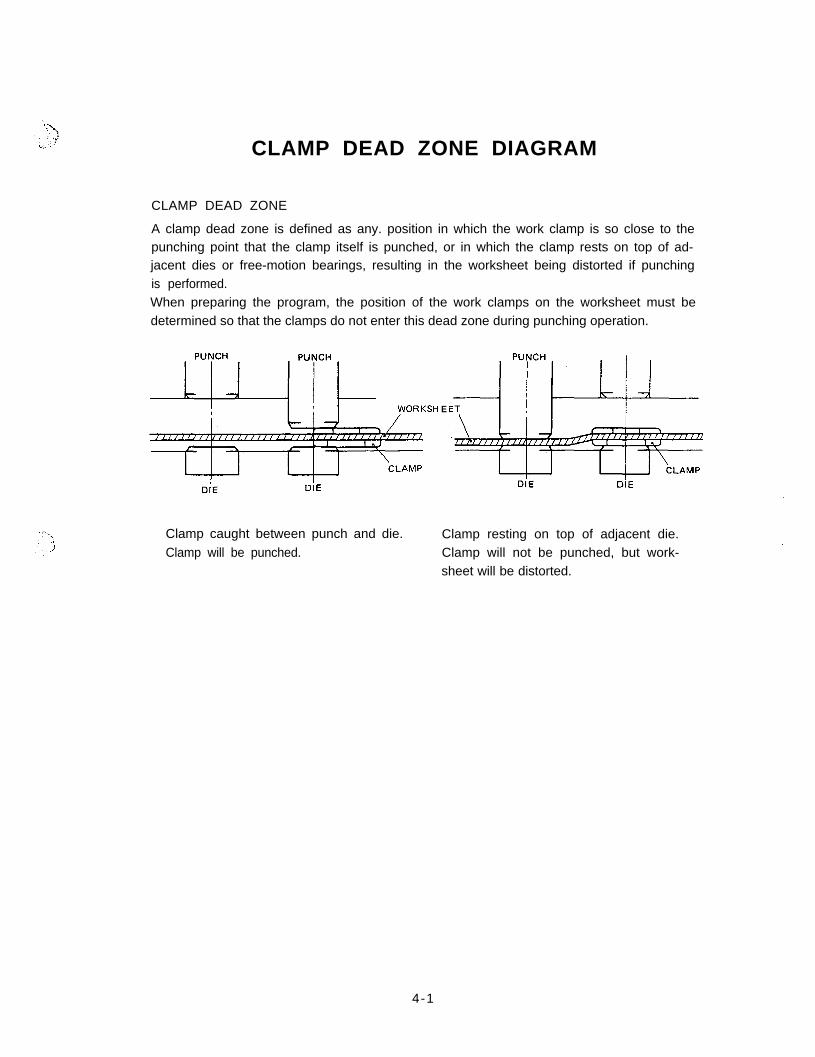
CLAMP DEAD ZONE
A clamp dead zone is defined as any. position in which the work clamp is so close to thepunching point that the clamp itself is punched, or in which the clamp rests on top of ad-jacent dies or free-motion bearings, resulting in the worksheet being distorted if punchingis performed.When preparing the program, the position of the work clamps on the worksheet must bedetermined so that the clamps do not enter this dead zone during punching operation.
WORKSH E
Clamp caught between punch and die.Clamp will be punched.
Clamp resting on top of adjacent die.Clamp will not be punched, but work-sheet will be distorted.
4-1
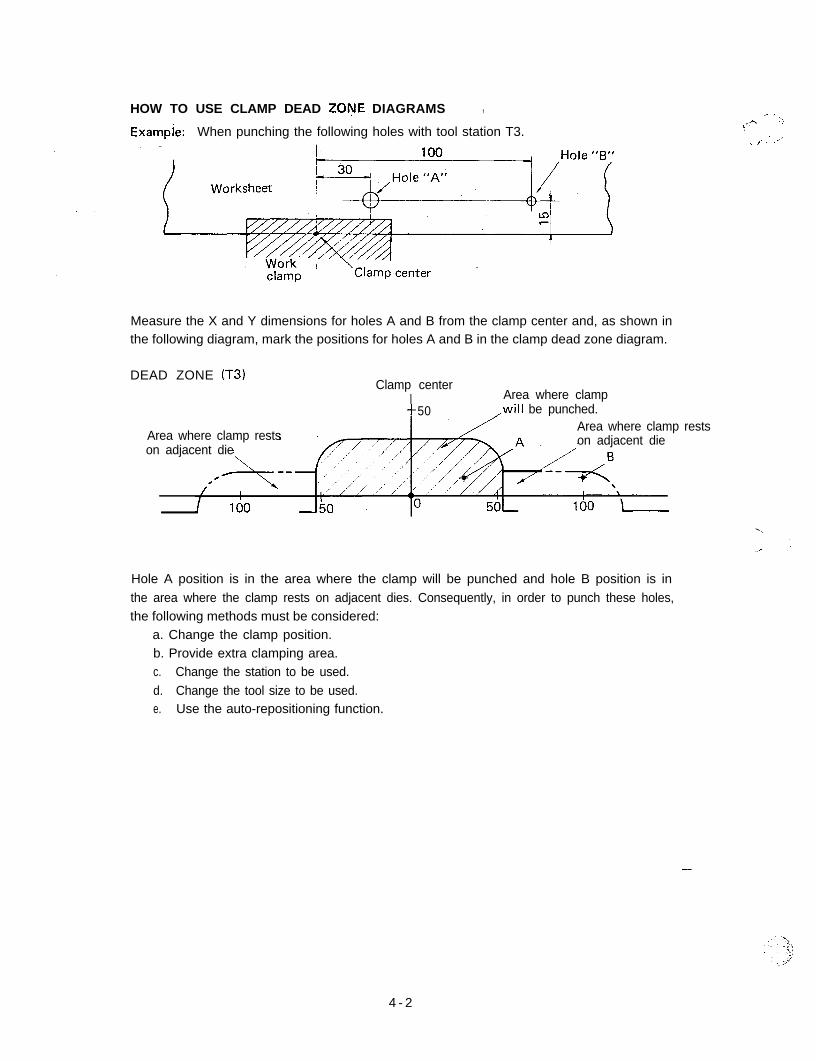
HOW TO USE CLAMP DEAD ZONE DIAGRAMS , .- i.
Exampje: When punching the following holes with tool station T3...A ::
-!
.- ,. : .-I’
Measure the X and Y dimensions for holes A and B from the clamp center and, as shown inthe following diagram, mark the positions for holes A and B in the clamp dead zone diagram.
DEAD ZONE (T3)Clamp center
50Area where clamp
,will be punched.
Area where clamp restson adjacent die
Area where clamp restson adjacent die
Hole A position is in the area where the clamp will be punched and hole B position is inthe area where the clamp rests on adjacent dies. Consequently, in order to punch these holes,the following methods must be considered:
a. Change the clamp position.b. Provide extra clamping area.c. Change the station to be used.d. Change the tool size to be used.e. Use the auto-repositioning function.
-
4 - 2
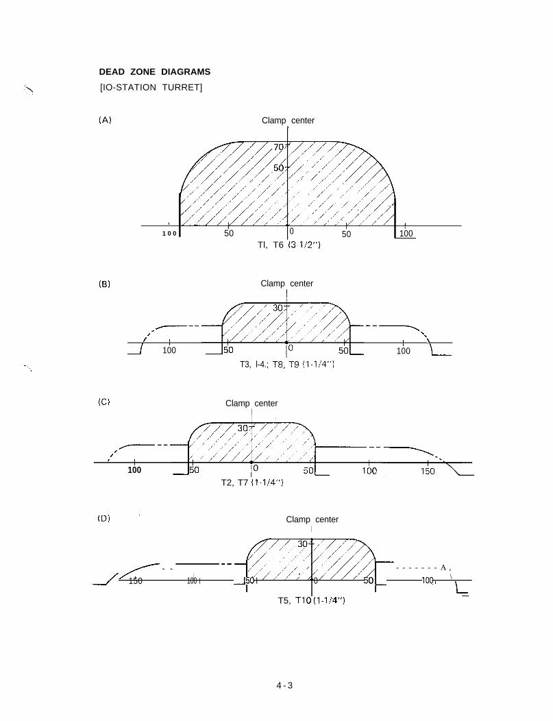
DEAD ZONE DIAGRAMS
[IO-STATION TURRET]
(Al
(B)
(C)
Clamp centerI
I II ,
1 0 0 0 I50 50 100
Tl, T6 (3-l/2”)
Clamp center
---. ---
,/
‘\I II
\I
100 100
T3, l-4.; T8;T9 (l-1/4”)
Clamp centerI
---,
/I I
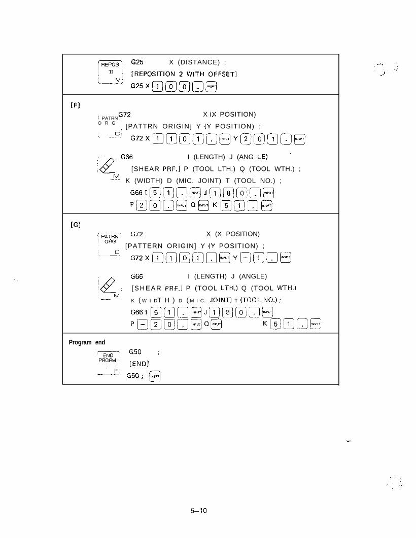
I
100T2, T7 (l-l/4”)
(D) ’ Clamp centerI
- - - - - - - - - A ,I/ , \150 100 I -50 I 0 50- IOQ I
-T5, TIO (I-1/‘4”!
4 - 3
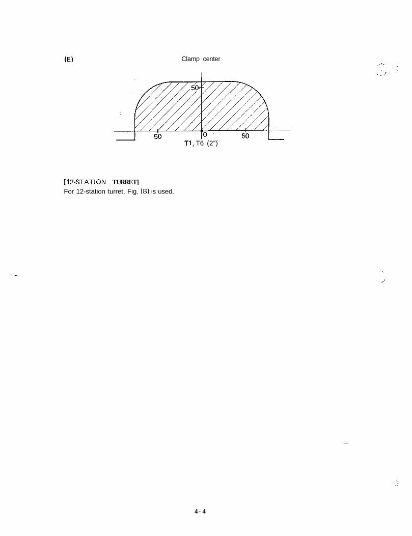
(El Clamp center
I
Tl, T6 (2”)
[12-STATION TURRET]For 12-station turret, Fig. (B) is used.
-
.‘..
I :
4-4
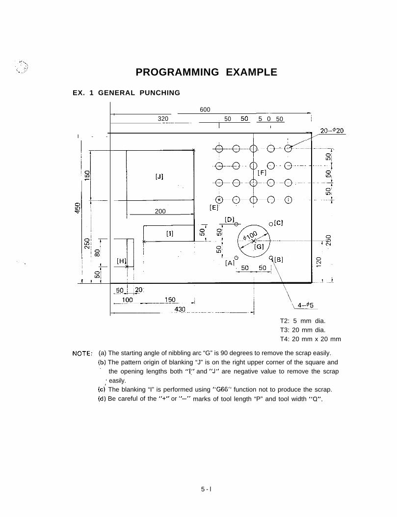
PROGRAMMING EXAMPLE
EX. 1 GENERAL PUNCHING
I - -
5d 200 _
600 LI320 , 50 ,.50 5 0 50 -I--.--___- II j I
- 20-420A’
T2: 5 mm dia.T3: 20 mm dia.T4: 20 mm x 20 mm
NOTE: (a) The starting angle of nibbling arc “G” is 90 degrees to remove the scrap easily.(b) The pattern origin of blanking “J” is on the right upper corner of the square and
’ the opening lengths both “I(’ and “J” are negative value to remove the scrap* easily.
(c) The blanking “I” is performed using “G66” function not to produce the scrap.(d) Be careful of the ‘I+” or “-” marks of tool length “P” and tool width “a”.
5 - l
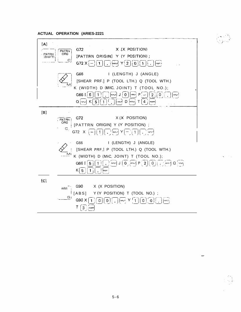
ACTUAL OPERATION
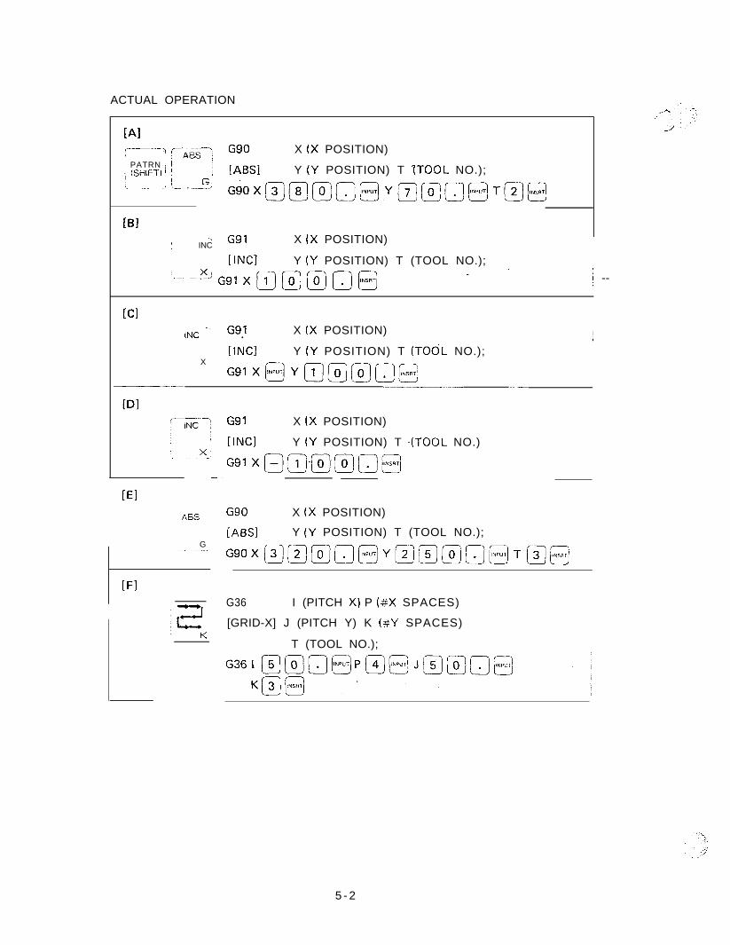
[Alc------\ czgg--; G90 X (X POSITION)j PATRN / ii (SHIFT1 ; ; LABS1 Y (Y POSITION) T ITOOL NO.);i-- _.: i_ . ..~_!z GiOX@@@Q@YE@a@TB@j
@IT G91; INC
X (X POSITION)
[INCI Y (Y POSITION) T (TOOL NO.);
I--, --?% Ggl X m @ @ IT) @ - .’ j --
[Cl-.’ G91INC . X (X POSITION)
X[INCI Y (Y POSITION) T (TOOL NO.);
G91X@Ym@@o@-__-.-- ---..------.-- .-
[El
ASS
G-.--_
IFI
G91 X (X POSITION)
IINCI Y (Y POSITION) T .(TOOL NO.)
G91 XQ@@@jJ@
G90 X (X POSITION)
[ABSI Y (Y POSITION) T (TOOL NO.);
GgoX~~~~~Y~~~~~~]T~~~
G36 I (PITCH X) P (#X SPACES)
[GRID-X] J (PITCH Y) K (#Y SPACES)
T (TOOL NO.);
5 - 2
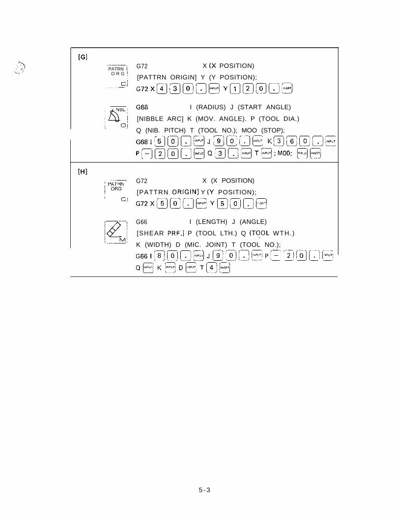
[Gl----.PATRN I
O R G j
ci_.. -. ’
G72 X (X POSITION)
[PATTRN ORIGIN] Y (Y POSITION);
G6B I (RADIUS) J (START ANGLE)
[NIBBLE ARC] K (MOV. ANGLE). P (TOOL DIA.)
Q (NIB. PITCH) T (TOOL NO.); MOO (STOP);
[HI;‘----.,/ p&y iI Cj
G72 X (X POSITION)
[PATTRN .ORIGIN] Y (Y POSITION);
G66 I (LENGTH) J (ANGLE)
[SHEAR PRF.] P (TOOL LTH.) Q (TOOL WTH.)
K (WIDTH) D (MIC. JOINT) T (TOOL NO.);
G66Immm@ J@g,n@t Pp’$mg@
Qfi+BD@T@@
5 - 3
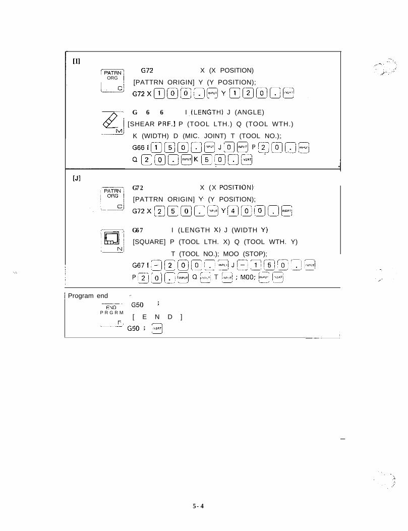
[IIm G72 X (X POSITION)/ ORG 1
/ [PATTRN ORIGIN] Y (Y POSITION);
-7 G 6 6
@
I ,(LENGTH) J (ANGLE)
i [SHEAR PRF.1 P (TOOL LTH.) Q (TOOL WTH.)--!!d K (WIDTH) D (MIC. JOINT) T (TOOL NO.);
G72 X (X POSITION)-
[PATTRN ORIGIN] Y (Y POSITION);
G67 I (LENGTH X) J (WIDTH Y)
[SQUARE] P (TOOL LTH. X) Q (TOOL WTH. Y)
T (TOOL NO.); MOO (STOP);
-i
j Program end _--EN--. G50 ;
P R G R M[ E N D ]
‘---” G50 ; @
1
i
/i
-
5-4
74
<..,-, :. . . . -’
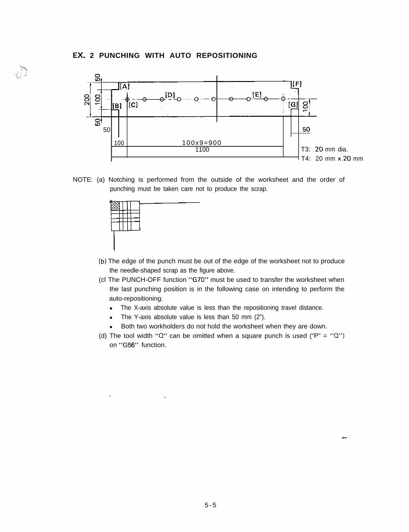
.EX. 2 PUNCHING WITH AUTO REPOSITIONING
01Lo’50 -50
100 100x9=9001100 T3: 20 mm dia.
T4: 20 mm x-20 mm
NOTE: (a) Notching is performed from the outside of the worksheet and the order ofpunching must be taken care not to produce the scrap.
(b) The edge of the punch must be out of the edge of the worksheet not to producethe needle-shaped scrap as the figure above.
(cl The PUNCH-OFF function “G70” must be used to transfer the worksheet whenthe last punching position is in the following case on intending to perform theauto-repositioning.l The X-axis absolute value is less than the repositioning travel distance.l The Y-axis absolute value is less than 50 mm (2”).l Both two workholders do not hold the worksheet when they are down.
(d) The tool width “0” can be omitted when a square punch is used (“P” = ‘IQ”)on “G66” function.
-
5 - 5
ACTUAL OPERATION (ARIES-2221
I (LENGTH) J (ANGLE)
[SHEAR PRF.] P (TOOL LTH.) Q (TOOL WTH.)
I--!?-’ K (WIDTH) D (MIC. J O I N T ) T ( T O O L N O . ) ;
ipisGG G72
I ~ [PATTRN
--~ ” G72 X /-=
X (x POSITION)
ORIGIN] Y (Y POSITION) ;
/~ ~- --- ---1x2 :
G66 I (LENGTH) J (ANGLE)
I [SHEAR PRF.] P (TOOL LTH.) Q (TOOL WTH.)
-----b!’ K (WIDTH) D (MIC. JOINT) T (TOOL NO.) ;
[Cl1 --\ G90
ASS 1X (X POSITION)
i [ A B S ] Y (Y POSITION) T (TOOL NO.) ;,.--.!?I
G90XQm@O]Ymmmo@
TpJ@
-
5 - 6
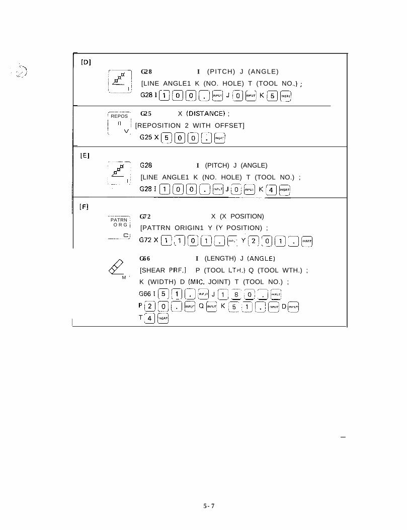
WIG28 I (PITCH) J (ANGLE)
[LINE ANGLE1 K (NO. HOLE) T (TOOL NO.
-- -.--~-.: REPOS I G25 X (.DISTANCE) ;I
II
i [REPOSITION 2 WITH OFFSET]
?“” G25X@m(0]fijj
[El.~
I--..- -7I (PITCH) J (ANGLE)
[LINE ANGLE1 K (NO. HOLE) T (TOOL NO.) ;
----‘--’
-----------I
PATRN :O R G i
tieM ’
G72 X (X POSITION)
[PATTRN ORIGIN1 Y (Y POSITION) ;
G66 I (LENGTH) J (ANGLE)
[SHEAR PRF.1 P (TOOL LTH.) Q (TOOL WTH.) ;
K (WIDTH) D (MIC. JOINT) T (TOOL NO.) ;
G661~~~@J~~~If~i’L$,.LLJ-
‘~17Sj~@Q~K~;~!~@Dj~
TH@
-
5-7
[GlPATRN
l#Il
G72 X (X POSITION)ORG
[PATTERN ORIGIN] ‘f (Y POSITION) ;
c G72X@12_)@QQ@Ya@n@
H
G66 I (LENGTH) J (ANGLE)
[ S H E A R PRF.1 P (TOOL LTH.) Q (TOOL WTH.1M
Program end
5 - 8
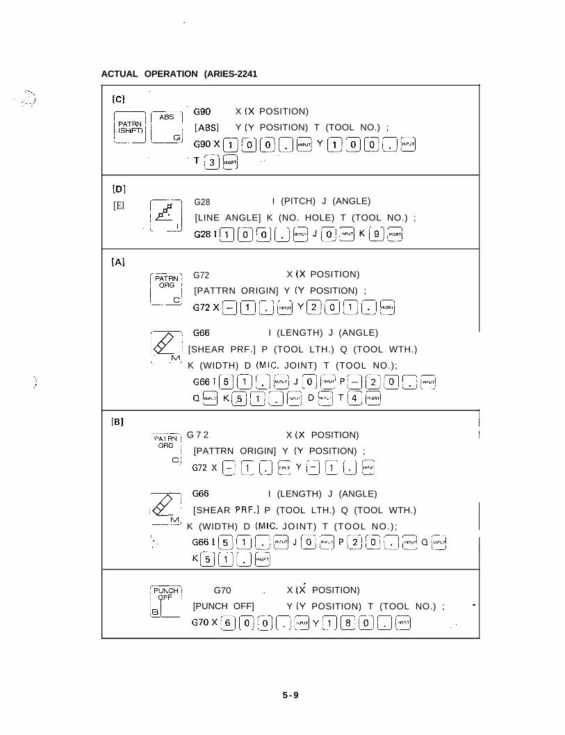
ACTUAL OPERATION (ARIES-2241
-.:I
GgOX (X POSITION)
[ABSI Y (Y POSITION) T (TOOL NO.) ;
DI[El G28 I (PITCH) J (ANGLE)
[LINE ANGLE] K (NO. HOLE) T (TOOL NO.) ;
G2BImmmn@JmBKm@
[AlG72 X (X POSITION)
[PATTRN ORIGIN] Y (y POSITION) ;
G72XBmn@ Y@@fiJn@
I (LENGTH) J (ANGLE)
j [SHEAR PRF.] P (TOOL LTH.) Q (TOOL WTH.)
‘-----!?!! K (WIDTH) D (MIC. JOINT) T (TOOL NO.);
[Bl--+A~~<J G 7 2 X (X POSITION)
0~ j [PATTRN ORIGIN] Y (Y POSITION) ;
----~!? G72 X a m 0 @ Y B @ 0 @
I (LENGTH) J (ANGLE)
[SHEAR PRF.1 P (TOOL LTH.) Q (TOOL WTH.)
p-k? K (WIDTH) D (M!C. JOINT) T (TOOL NO.) ;
fwj G70 . X (X POSITION)
EIJ [PUNCH OFF] Y (Y POSITION) T (TOOL NO.) ; -
G70X~@f-3-33~[~)(35 ~.
5 - 9
(REposj G25 X (DISTANCE) ;
i IIvj ~;FQQWW;;FSETI
. ~NSRT
)G72
PATRN :X (X POSITION)
O R G: [PATTRN ORIGIN] Y (Y POSITION) ;
'-----% G72X@(+J@Q@Y@m[_1!0@
.’_~~
:k?
G66 I (LENGTH) J (ANG LEf
[SHEAR PRF.] P (TOOL LTH.) Q (TOOL WTH.) ;
?! K (WIDTH) D (MIC. JOINT) T (TOOL NO.) ;
G661@12_j~@J~~@~@
P@@m@Q@K,ymnm
[Gl[p-i G72 X (X POSITION), j [PATTERN ORIGIN] Y (Y POSITION) ;
'-> G72XmQ@aO@YBmo@
_.
'kz
G66 I (LENGTH) J (ANGLE)
: [ S H E A R PRF.1 P (TOOL LTH.1 Q (TOOL WTH.);. _.._. -Y ’
K ( W I DT H ) D ( M I C. JOINT) T (~00~ ~0.1 ;
G66I@@a@Jllj@&!J@
PQ@mI-I-]@Q@ K@mn@
Program end
!T&b--.; G50 ;
:.PRGRM ! [END1
IF; G50; @
5-70
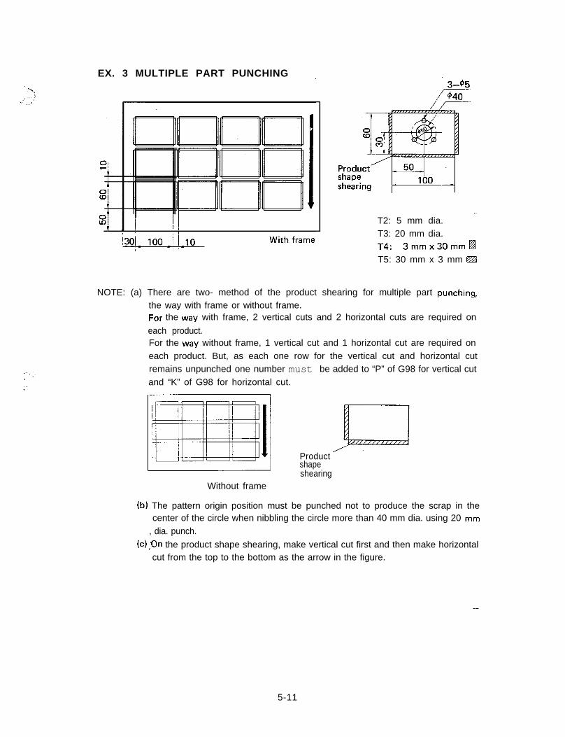
EX. 3 MULTIPLE PART PUNCHING ~
.--,,_,
:. ’
T2: 5 mm dia.T3: 20 mm dia.f4: 3mmx30mm~T5: 30 mm x 3 mm @ZA
NOTE: (a) There are two- method of the product shearing for multiple part punching,the way with frame or without frame.For the way with frame, 2 vertical cuts and 2 horizontal cuts are required on
each product.For the way without frame, 1 vertical cut and 1 horizontal cut are required oneach product. But, as each one row for the vertical cut and horizontal cutremains unpunched one number must be added to “P” of G98 for vertical cutand “K” of G98 for horizontal cut.
Without frame
Productshapeshearing
(b) The pattern origin position must be punched not to produce the scrap in thecenter of the circle when nibbling the circle more than 40 mm dia. using 20 mm
, dia. punch.
(c) ,On the product shape shearing, make vertical cut first and then make horizontalcut from the top to the bottom as the arrow in the figure.
-
5-11
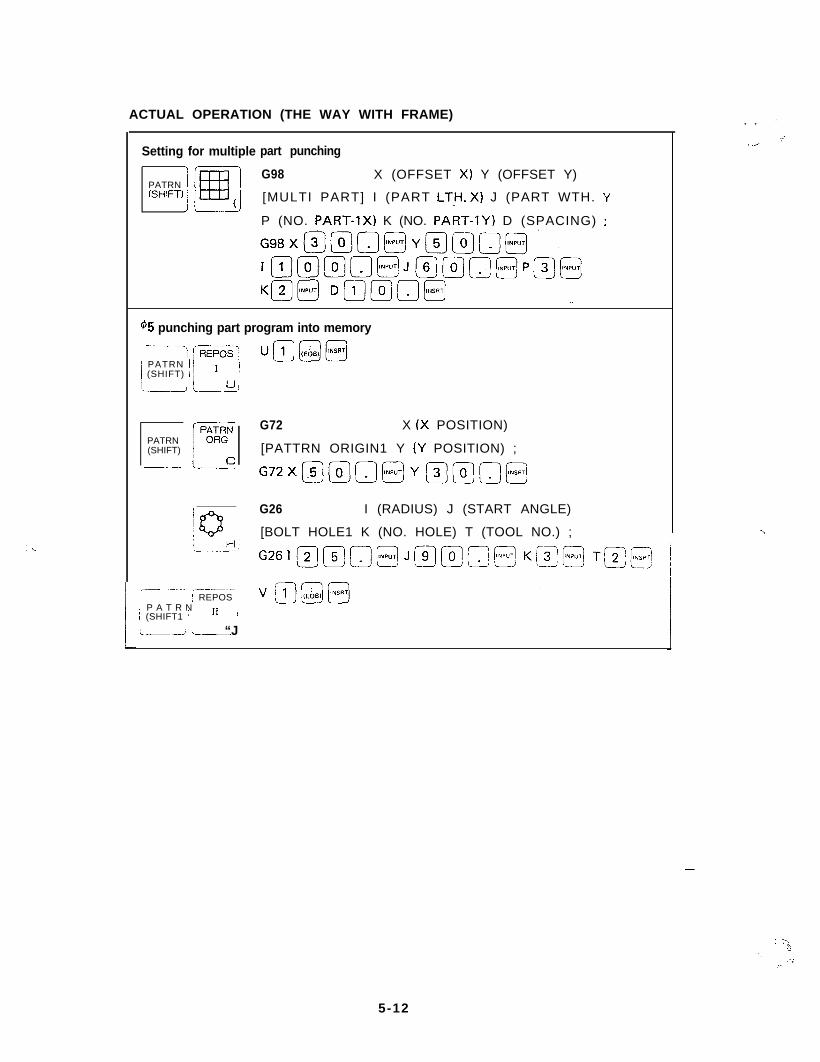
ACTUAL OPERATION (THE WAY WITH FRAME)
I
Setting for multiple part punching
PATRN(SHIFT)
G98 X (OFFSET X) Y (OFFSET Y)
[MULTI PART] I (PART LT.l-l. X) J (PART WTH. Y
P (NO. PART-lx) K (NO. PART-IY) D (SPACING) ;
45 punching part program into memory.---- --,/ /-KG55
j PATRN I /) (SHIFT) i /
1 //
‘.-A I-9
PATRN(SHIFT)
mIi
G72 X (X POSITION)
[PATTRN ORIGIN1 Y (Y POSITION) ;
G72X@@O@Ym@o@
G26 I (RADIUS) J (START ANGLE)
[BOLT HOLE1 K (NO. HOLE) T (TOOL NO.) ;
_-- ._..~ _--_._I REPOS I
P A T R Ni (SHIFT1 ’ / ‘I !
!I__-, “Jj___
. . .’
7j _,..
-..
-
_ : Y:>
.‘.,.‘,
,”
5-12
,:
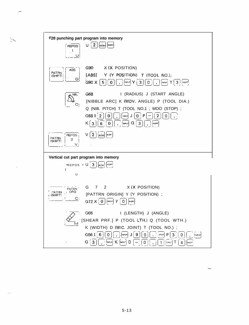
420 punching part program into memory
X (X POSITION)
Y (Y POSITION) T (TOOLS NO.);
G’ “g::@mo’-;IY@mo@T&j@
I (RADIUS) J (START ANGLE)
[NIBBLE ARC] K (MOV. ANGLE) P (TOOL DIA.)
Q (NIB. PITCH) T (TOOL NO.1 ; MOO (STOP) ;
G,,I@(oln@Jr;;7PBm@n
Km@mn@QBo@
Vertical cut part program into memory
- - u’p-J[(EbB’j@R E P O S
1
U
~-. - - - - ,i PATRN / G 7 2 X (X POSITION)
’ PATRN I’ ORG i! (SHIFT1 j j [PATTRN ORIGIN] Y (Y POSITION) ;
‘---A i--ci G72 x m @ y @ @
I (LENGTH) J (ANGLE)
/ [SHEAR PRF.] P (TOOL LTH.) Q (TOOL WTH.)
k (WIDTH) D (MIC. JOINT) T (TOOL NO.) ;
G66Im(Oj.@ Jmmo@ Pmm(Tj@
I Qmo@K@Dm@mm@[T@E
-
5-13
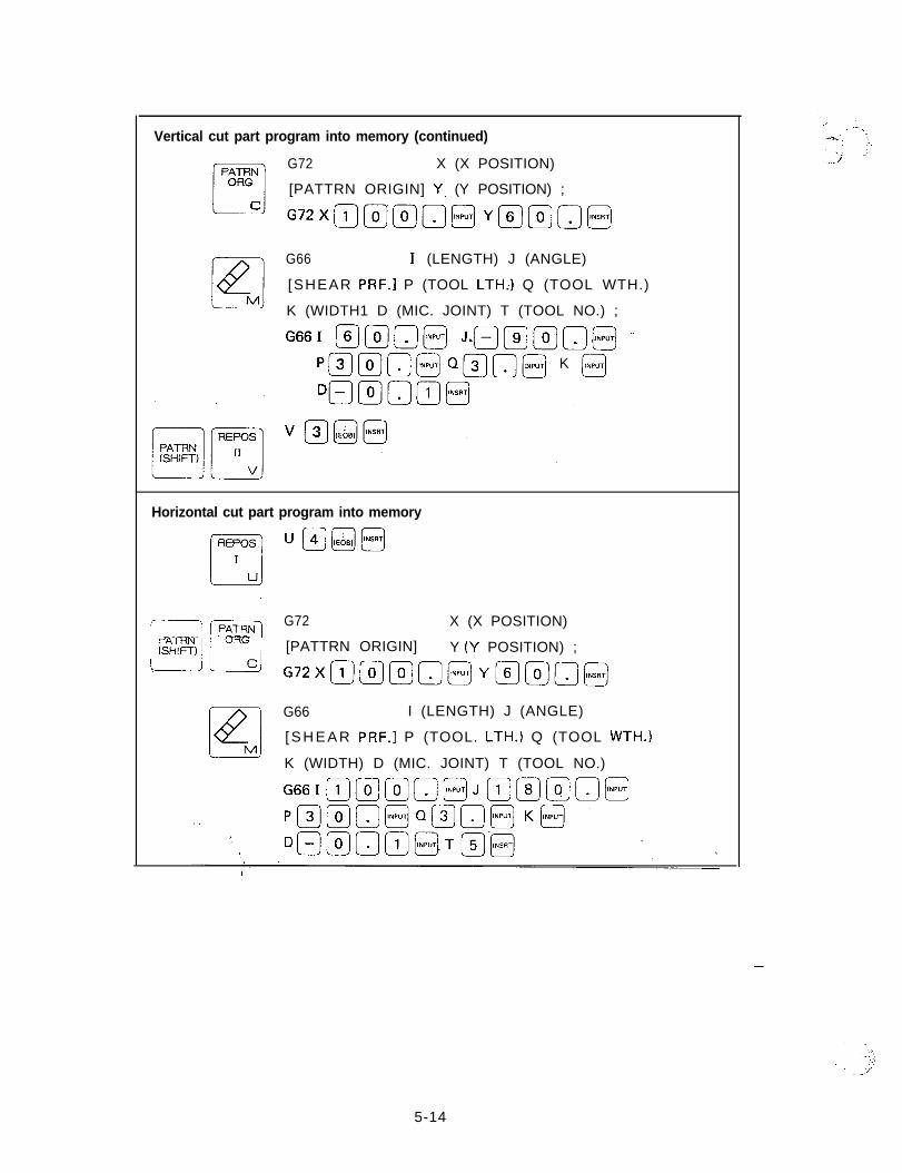
Vertical cut part program into memory (continued)
G72 X (X POSITION)
[PATTRN ORIGIN] Y. (Y POSITION) ;
G72XII_]@@O@Ymmn@
G66 1. (LENGTH) J (ANGLE)
[SHEAR PRF.1 P (TOOL LTH.) Q (TOOL WTH.)
K (WIDTH1 D (MIC. JOINT) T (TOOL NO.) ;
G661 mmo@ JsQ@mo@ -’
P@@n@ “a[@ K @
Horizontal cut part program into memory
ur4]@@
‘i /?iKi-jG72 X (X POSITION)
’ PATRN ” ORG )(SHIFT) 1 / [PATTRN ORIGIN] Y (Y POSITION) ;
Idu G72XmmmQ@YmmO@
G66 I (LENGTH) J (ANGLE)
[ S H E A R PRF.1 P (TOOL. LTH.) Q (TOOL WTH.1
K (WIDTH) D (MIC. JOINT) T (TOOL NO.)
G66IC1_]llj7~~@J~@~~~
-
5-14
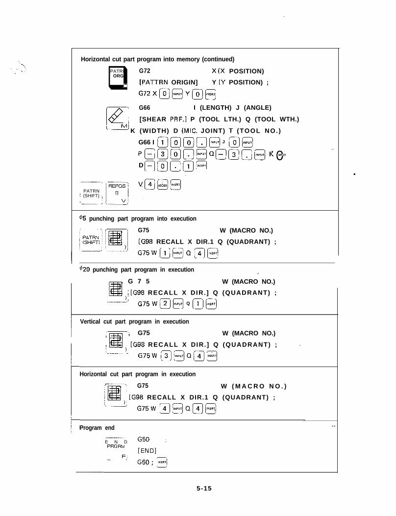
.
I
LI
/
Horizontal cut part program into memory (continued)
PATRNq G72ORG
X (X POSITION)
[PATTRN ORIGIN] Y (Y POSITION) ;
c G72X@@Y@@
G66 I (LENGTH) J (ANGLE)
[SHEAR PRF.] P (TOOL LTH.) Q (TOOL WTH.)
K (WIDTH) D (MIC. JOINT) i (TOOL NO. )
- -__I
j PATRN /; (SHIFT) j
id ‘L
G66 I
clD -O
0.0INPUTf&q
0INPUT J
QEI 0lNP”T lz .~0lNP”T
45 punching part program into execution
G75 W (MACRO NO.)
[G98 RECALL X DIR.1 Q (QUADRANT) ;
G75Wm@Qm@
$20 punching part program in execution IG 7 5 W (MACRO NO.)
; [G98 RECALL X DIR. ] Q (QUADRANT) ;
------’ -G75 W m @ Q II] @
Vertical cut part program in execution
,--I, G75I W (MACRO NO.)
I / [G98 RECALL X DIR. ] Q (QUADRANT) ;
G75W B@Qm@
Horizontal cut part program in execution
G75 W ( M A C R O N O . )
1 [G98 RECALL X DIR.1 Q (QUADRANT) ;
‘-_A G75W m@Qm@
Program end -
/
_--__-E N D G50 ;PRGRM !
j [END1
-FI G5(‘J; @
.
5-15
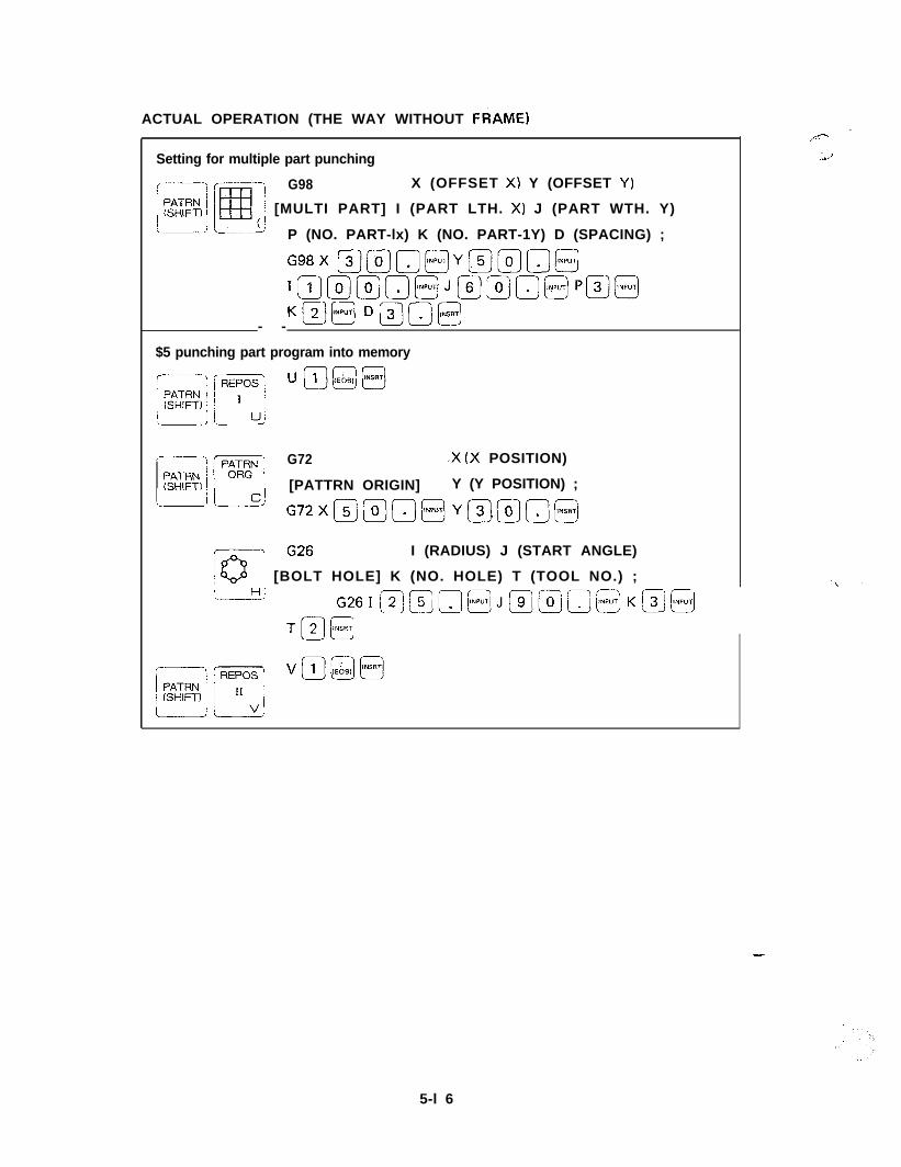
ACTUAL OPERATION (THE WAY WITHOUT FRAME)
Setting for multiple part punching
G98 X (OFFSET X) Y (OFFSET Y)
: [MULTI PART] I (PART LTH. X) J (PART WTH. Y)
P (NO. PART-lx) K (NO. PART-1Y) D (SPACING) ;
G98X @@o@Y@@n@
I~r;;7~~@Jf?J~~~+j@
KsI’“p”Tl Dmo@- -
$5 punching part program into memory
/---\ G72 .X (X POSITION)
[PATTRN ORIGIN] Y (Y POSITION) ;
Lid G72Xmmo@Yo@o@
I (RADIUS) J (START ANGLE)
j [BOLT HOLE] K (NO. HOLE) T (TOOL NO.) ;
‘--> G26I@@o@J@@r,@Km@
+J[‘“..‘l
.,,..--
.;,J
-
5-l 6
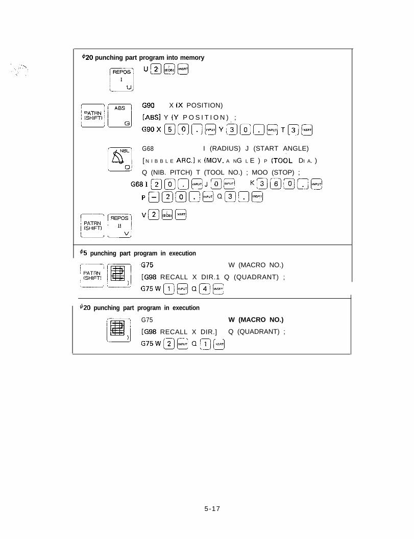
420 punching part program into memory
lJB(IE681j@
G90 X (X POSITION)
[ABS] Y (Y P O S I T I O N ) ;
G90Xm@a@Ya@o@T@@
G68 I (RADIUS) J (START ANGLE)
[ N I B B L E ARC.] K (MOV. A NG L E ) P (TOOL DI A. ).~
Q (NIB. PITCH) T (TOOL NO.) ; MOO (STOP) ;
G68I@@n@J@@ KQ@@n@
p@m@o@Q@OB
V11_1@@
$5 punching part program in execution
-G75 W (MACRO NO.)
i [G98 RECALL X DIR.1 Q (QUADRANT) ;
G75Wll_i@ OR@
420 punching part program in execution
G75 W (MACRO NO.)
[G98 RECALL X DIR.] Q (QUADRANT) ;
G75Wm@Qm@
5-17
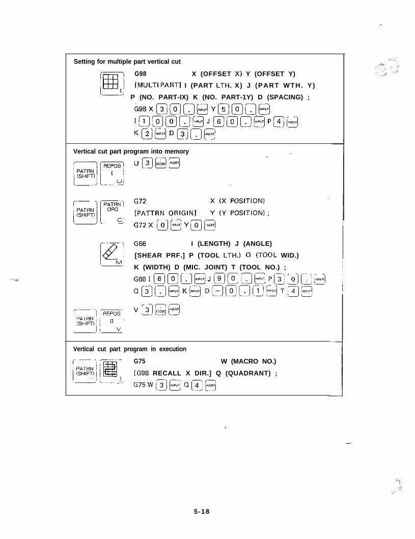
_-
Setting for multiple part vertical cut
G98 X (OFFSET X1 Y (OFFSET Y)
[MULTI PART1 I (PART LTH. X) J (PART WTH. Y)
P (NO. PART-IX) K (NO. PART-1Y) D (SPACING) ;
698X@@o@Y@@o@
I~@@~‘~J~l;s7~@P@@
K@mD@n@
Vertical cut part program into memory
I (LENGTH) J (ANGLE)
[SHEAR PRF.] P (TOOL LTH.) Q (TOOL WID.)
K (WIDTH) D (MIC. JOINT) T (TOOL NO.) ;
G&$-i--J~~@j@~~~F’~~~@
Q@o@K@ D~~~@@Tl~@
Vertical cut part program in execution
G75 W (MACRO NO.)
[G98 RECALL X DIR.] Q (QUADRANT) ;
G75W-j33Q@@
5-18
“\i,’
::..;’
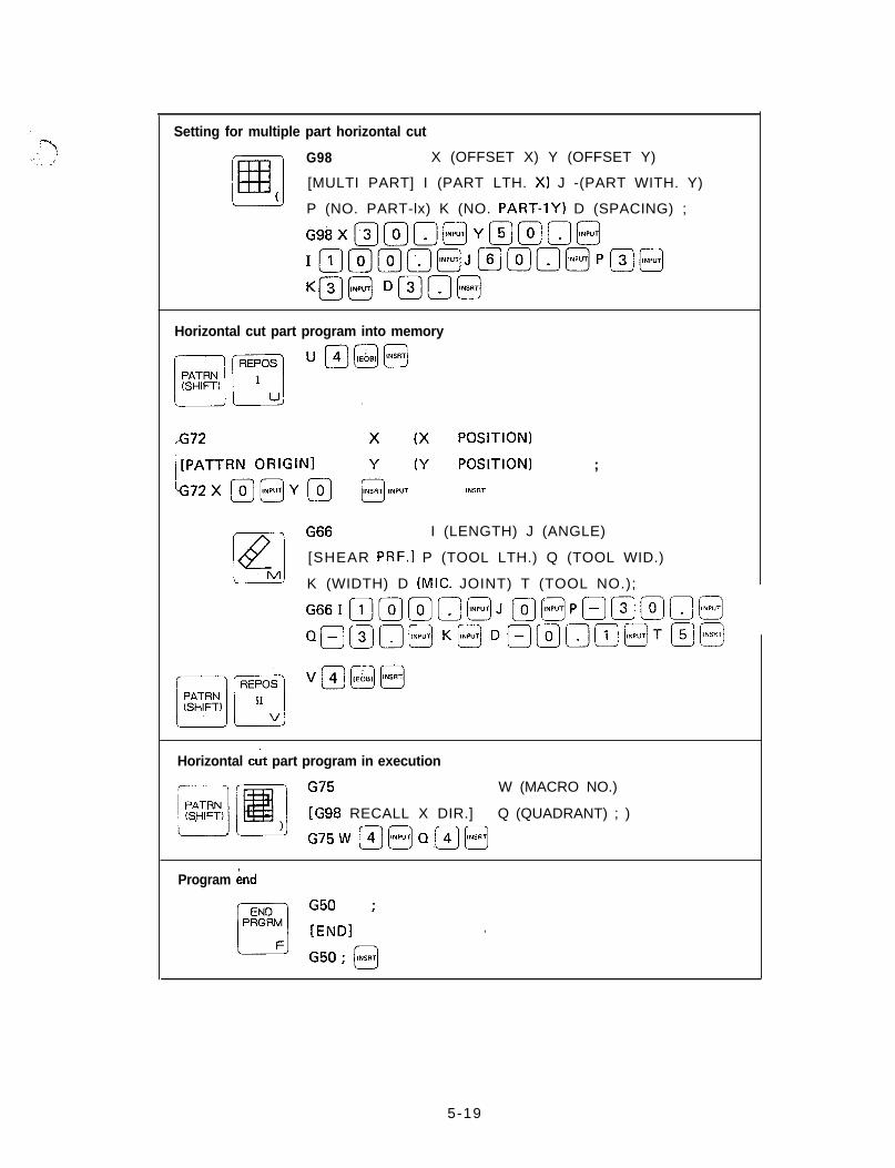
Setting for multiple part horizontal cut
G98 X (OFFSET X) Y (OFFSET Y)
[MULTI PART] I (PART LTH. X) J -(PART WITH. Y)
P (NO. PART-lx) K (NO. PART-1Y) D (SPACING) ;
G98Xm@omYBmo@
Im@@a@J@@n@PB@
Km@ Dmn@
Horizontal cut part program into memory
IFi r\i;f;E;;Nb ; I: :::t:::; ;
lNP”T INSAT
G66 I (LENGTH) J (ANGLE)
[SHEAR PRF.1 P (TOOL LTH.) Q (TOOL WID.)
K (WIDTH) D (MIC. JOINT) T (TOOL NO.);
G66III_)@)ma@J m@Pommo@
QQQo@ K@Dmmom@TQm
Horizontal cut part program in execution
G75 W (MACRO NO.)
[G98 RECALL X DIR.] Q (QUADRANT) ; )
G75W mmQ.m@
Program bnd
,
5-19
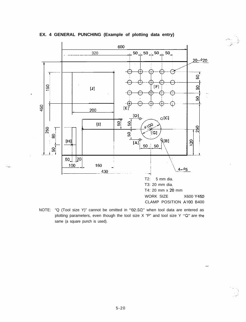
EX. 4 GENERAL PUNCHING (Example of plotting data entry)
i
320-___-.---
[Jl
I[II
T2: 5 mm dia.T3: 20 mm dia.T4: 20 mm x 20 mm
WORK SIZE X600 Y450CLAMP POSITION A100 B400
NOTE: “Q (Tool size Y)” cannot be omitted in “02:S.Q” when tool data are entered asplotting parameters, even though the tool size X “P” and tool size Y “0” are thesame (a square punch is used).
,
-
5-20
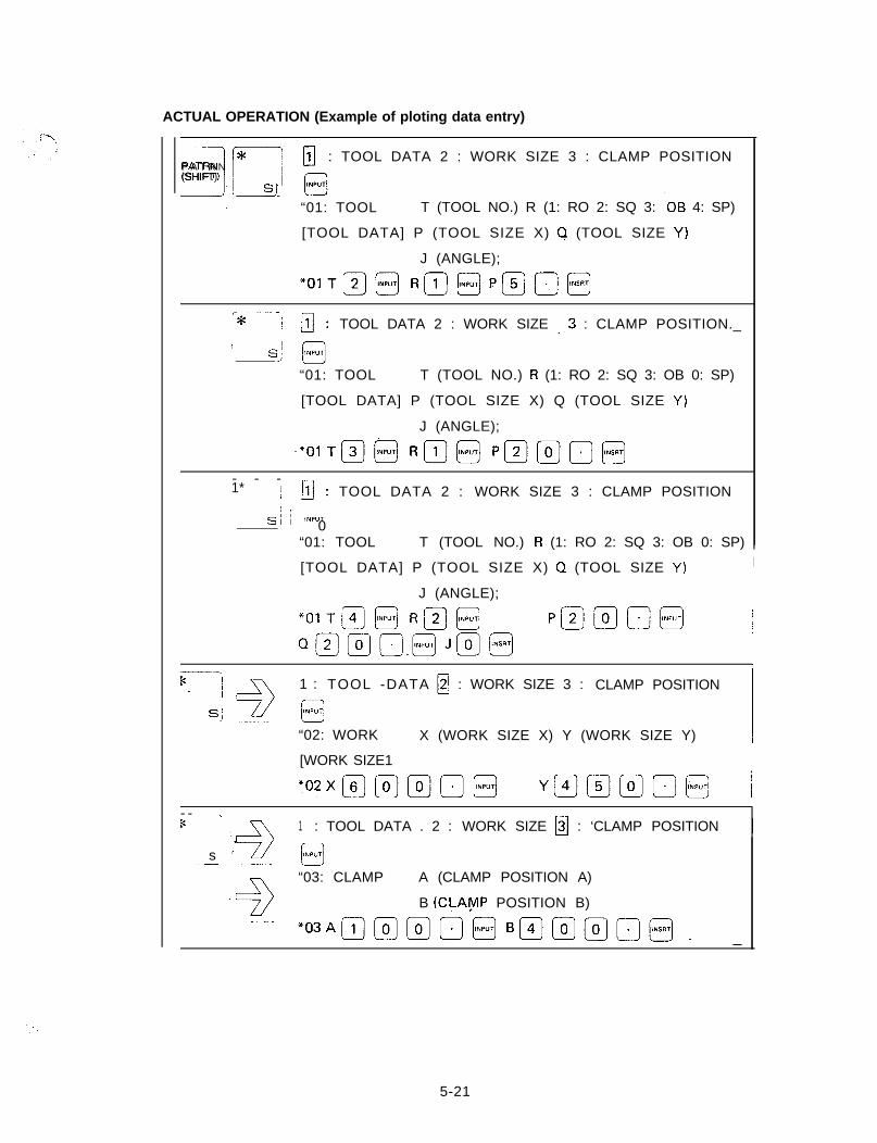
ACTUAL OPERATION (Example of ploting data entry)
III,
P A T R N 170 : TOOL DATA 2 : WORK SIZE 3 : CLAMP POSITION(SHIFT)
! sj ‘NP”TCl
“01: TOOL T (TOOL NO.) R (1: RO 2: SQ 3: -0B 4: SP)
[TOOL DATA] P (TOOL SIZE X) Q (TOOL SIZE Y)
J (ANGLE);
*()I+)@ Rm@+Jo@
i--.. -/* / /j: TOOL DATA 2 : WORK SIZE /3 : CLAMP POSITION._1 s j INPUT
JJ“01: TOOL T (TOOL NO.) R (1: RO 2: SQ 3: OB 0: SP)
[TOOL DATA] P (TOOL SIZE X) Q (TOOL SIZE Y)
J (ANGLE);
-*,,,m@ Rm@ Pmmo@
- - -1* / jiJ: TOOL DATA 2 : WORK SIZE 3 : CLAMP POSITION
I s j lNP”T: 0
“01: TOOL T (TOOL NO.) R (1: RO 2: SQ 3: OB 0: SP) !
[TOOL DATA] P (TOOL SIZE X) Q (TOOL SIZE Y) I
J (ANGLE);//
*OlTm@R@@ P@mB@ I
Qr2)os@J@@I
!tc--i
-____ -12:
1 : TOOL -DATA R : WORK SIZE 3 : CLAMP POSITION
S; 0lNP”T
“02: WORK X (WORK SIZE X) Y (WORK SIZE Y) /
[WORK SIZE1
702x(6)@@]@ YpJBpi-JD@ j
- - --1K
~__ *+
1 : TOOL DATA . 2 : WORK SIZE H : ‘CLAMP POSITION j
s f @
“03: CLAMP A (CLAMP POSITION A)
B (CLAYP POSITION B)
*OW~@~o@B~@@o~, _
5-21
,--
[Al
ABS
13
G90
[ABSIG
G90 X
X (X POSITION)
Y (Y POSITION) T (TOOL NO.);
(--iiF-) Ggl X (X POSITION)
[INCI Y (Y POSITION) T (TOOL NO.);
G91Xmm@o@ _ ~_.~.~_. .- ..-- _-...---
[ClINC
r---i
G91 X (X POSITION)
[INCl Y (Y POSITION) T (TOOL NO.);
[DlX (X POSITION)
Y (Y POSITION) T (TOOL NO.);
[El------’ G90; ABS 1
X (X POSITION)
/ [Fl
I r--l-=3 G36: imp- [GRID-XlL----KlI
G36 I @
I (PITCH X) P (#X SPACES)
J (PITCH Y) K (#Y SPACES)
-..- 1.
.:, ,I.
,’
‘.., i,
5-22
‘,.,
I
..’ ;.
[GlPATRN
EG72 X (X POSITION).
ORG[PATTRN ORIGIN] Y (Y POSITION);
c’ G72X@@mo@ Ymm@a[INSRIl
p.K’
$3
G68 I (RADIUS) J (START ANGLE) .
I [NIBBLE ARC] K (MOV. ANGLE) P (TOOL DIA.)L-9
[HI~-. ..-, G72
; PATRNX (X POSITION)
, ORG/ [PATTRN ORIGIN] Y (Y POSITION) ;! ~-- -’ G72 X @ m 0 @ Y @ @ 0 @
lr--.-- .-’G66
I@
I (LENGTH) J (ANGLE)
; [SHEAR PRF.] P (TOOL LTH.) Q (TOOL WTH.)
--.-!, K (WIDTH) D (MIC. JOINT) T (TOOL NO.);
G66I@@n@J@jmn@Pfl@mo@
QfEjj~@~(Gljj~m@
5-23
IIIPATRN
i - 1
G72’ .X (X POSITION)ORG
[PATTRN ORIGIN] Y (Y POSITION);
c G72X@mmo@YIljiZ_jmo@
P
G66 I (.LENGTH) J (ANGLE)
--![SHEAR PRF.1 P (TOOL LTH.) 0 (TOOL WTH.)
M K (WIDTH) D (MIC. JOINT) T (TOOL NO.);
G66Immmo@J@@ P@.@o@
QQ~[@K~@~@
tJ1PATRN ,
E
G72 X (X POSITION)ORG
j [PATTRN ORIGIN] Y (Y POSITION);
c’ G72X@@@a@Y@@@o@
Ela
G67
I [
I (LENGTH X) J (WIDTH Y)
SQUARE] P (TOOL LTH. X) Q (TOOL WTH. Y)NJ
Program end
.
-
5-24
DISPLAYED FORMAT ON CRT
r---lPATRN(SHIFT)
i.)I%%
-Fig-
-B,
ii
PATRN(SHIFT1
\ ,
G92 X (X POSITION)
[COORDI Y (Y POSITION) ;
w G72 X (X POSITION)
C[PATTRN ORIGIN1 Y (Y POSITION) ;
O F F S T ’
clj
G70
[PUNCH OFF1
X (X POSITIOi)
Y (Y POSITION) T (TOOL NO.) ;
! _: :.
.‘i’
i PATRNiij ! P&d /
; (SHIFT) , /
I J i
G93
[OFFSET]
GO4
[DWELL]
G50 ;
[END1
G90
LABS1
G26
[BOLT HOLE]
G28
[LINE ANGLE]
G29
tARC1
(OFFSET X)
(OFFSET Y) ;
(LENGTH OF PAUSE) ;
(X POSITION)
(Y POSITION) T (TOOL NO.) ;
RADIUS) J (START ANGLE)
(NO. HOLE) T (TOOL NO.) ;
PITCH) J (ANGLE),K (NO. HOLE) T (TOOL NO.) ;
-
I (RADIUS) J (START ANGLE)
K (NO. HOLE) P (ANGLE INCR.)
T (TOOL NO.) ;
6 - l
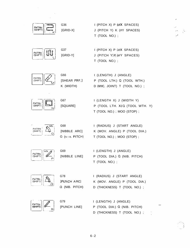
PATRN(SHIFT)
,------I PATRN Ii (SHIFT) I
/L---’
PATRN
L.)
(SHIFT)
G36
[GRID-X]
G37
[GRID-Y]
G66 I (LENGTH) J (ANGLE)
[SHEAR PRF.] P (TOOL LTH.) 0 (TOOL WTH.)
K (WIDTH) D (-MIC. JOINT) T (TOOL NO.) ;
G67
[SQUARE]
G68
[NIBBLE ARC]
Q (N I B. PITCH)
G69
[NIBBLE LINE]
G78
[PUNCH ARC1
0 (NIB. PITCH)
G79
[PUNCH LINE]
r
I (PITCH X) P (#X SPACES)
J (PITCH Y) K (#Y SPACES) ;.... - “.:T (TOOL NO.) ; 2
I (PITCH X) P (#X SPACES)
J (PITCH Y) K (#Y SPACES)
T (TOOL NO.) ;
I (LENGTH X) J (WIDTH Y)
P (TOOL LTH. X) Q (TOOL WTH. Y)
T (TOOL NO.) ; MOO (STOP) ;
I (RADIUS) J (START ANGLE)
K (MOV. ANGLE) P (TOOL DIA.)
T (TOOL NO.) ; MOO (STOP) ;
I (LENGTH) J (ANGLE)
P (TOOL DIA.) 0 (NIB. PITCH)
T (TOOL NO.) ;
I (RADIUS) J (START ANGLE)
K (MOV. ANGLE) P (TOOL DIA.)
D (THICKNESS) T (TOOL NO.) ;
I (LENGTH) J (ANGLE)
P (TOOL DIA:) 0 (NIB. PITCH)-
D (THICKNESS) T (TOOL NO.) ; :
6 - 2
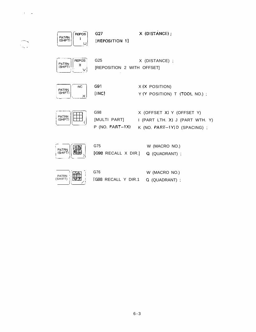
: -
. . ..--._‘i
‘/-.. .~
G25 X (DISTANCE) ;
[REPOSITION 2 WITH OFFSET]
G91
[INCIX (X POSITION)
Y (Y POSITION) T -(TOOL NO.) ;
G98 X (OFFSET X) Y (OFFSET Y)
[MULTI PART] I (PART LTH. X) J (PART WTH. Y)
P (NO. PART-lx) K (NO. PART-1Y) D (SPACING) ;
G75 W (MACRO NO.)
[G98 RECALL X DIR.] Q (QUADRANT) ;
PATRN(SHIFT)
-i G76 W (MACRO NO.)I
[G98 RECALL Y DIR.1i
0 (QUADRANT) ;
6 - 3