Embed Size (px)
Citation preview
Programming Cochlear Implants
Second Edition
Jace Wolfe, PhDErin C. Schafer, PhD

Contents
Foreword by Teresa A. Zwolan xiPreface xiiiAcknowledgments xivContributors xv
1 Basic Components and Operation of a Cochlear Implant 1Jace Wolfe, Erin C. Schafer, and Sara NeumannBasic Operation of Cochlear Implants 2Basic Components of Current Cochlear Implant Systems 4Advanced Bionics Corporation 7
Naída CI Q70 Sound Processor 7Neptune Sound Processor 17Harmony Sound Processor 19HiRes 90K Advantage Implant 22
Cochlear Corporation 26Nucleus 6 Sound Processor 27Nucleus Freedom Internal Device 42CI422 Implant 44Nucleus Hybrid Cochlear Implant 44CI512 Implant 45
MED-EL Corporation 45OPUS 2 Sound Processor 46RONDO 49CONCERT Internal Device 53SONATA TI100 Internal Device 53PULSAR CI100 Internal Device 54MED-EL Electrode Array Options 55MED-EL SYNCHRONY Cochlear Implant System 57
Key Concepts 59
2 Basic Terminology of Cochlear Implant Programming 61Parameters Affecting Signal Coding in the Intensity Domain 61
Stimulation Levels 61Threshold of Stimulation 62Upper-Stimulation Levels 64Current Amplitude and Pulse Width 65Mapping Acoustical Inputs Into the Electrical Dynamic Range 66
Parameters Affecting Signal Coding in the Frequency Domain 68Electrode Contact Versus Channel 68Virtual Electrodes (Current Steering) 70Frequency Allocation 71

vi Programming Cochlear Implants
Parameters Affecting Signal Coding in the Time Domain 71Stimulation Rate 71
Basic Cochlear Implant Terminology 74Electrode Coupling Strategy/Stimulation Mode 74Sequential Versus Simultaneous Stimulation 78Interpolation 78Sweeping 79Loudness Balancing 80Radio Frequency (RF) 80Telemetry 80Impedance 81Voltage Compliance 83Mixing Ratio 83
Basic Cochlear Implant Signal Coding Strategies 84Continuous Interleaved Sampling (CIS) 84HiResolution (HiRes) Sound Processing 86n-of-m Strategies 87Spectral Peak (SPEAK) 87Advanced Combination Encoder (ACE) 88Fine Structure Processing (FSP) 90Simultaneous Analog Stimulation (SAS) 90
Key Concepts 91
3 Basic Principles of Programming 93Preactivation Procedures 93
Realistic Expectations Prior to Activation 93Reviewing Logistics of Cochlear Implantation 99Familiarity with Cochlear Implant Hardware 102Setting the Stage 102
Programming After Implantation 103Physical Evaluation 103Selecting a Signal Coding Strategy 105Streamlined Versus Comprehensive Programming 106Measuring Stimulation Levels 106Adjustments to Special Parameters 124
Key Concepts 128
4 Programming Advanced Bionics Implants 129 Advanced Bionics CPI-3 Programming Interface 129Programming Advanced Bionics Sound Processors 130
Programming Software 130Patient Information Entry 131Connecting the Sound Processor and Conducting the Electrode 132
Impedance MeasurementCreating a Program in SoundWave 2.2 Software 136Selecting a Sound Processing Strategy 136Setting Stimulation Levels and Stimulation Rate 139Additional Programming Parameters 146Loading Programs Into Advanced Bionics Sound Processors 158
Contents vii
Datalogging 159Neural Response Imaging (NRI) 160Hearing Assistance Technologies 162Programming Previous Generations of Advanced Bionics Implants 164
Key Concepts 165
5 Programming Cochlear Devices 167Programming the Nucleus 6 System 167
Measure Impedances 170Open or Create MAP 173Setting Stimulation Levels 175Write to Processor 194
Programming Previous Generations of Nucleus Implants 212Key Concepts 213
6 Programming MED-EL Cochlear Implants 215Jace Wolfe, Erin C. Schafer, and Sara NeumannPatient Information Entry 215Connecting the Sound Processor and Conducting the Electrode Impedance 217
MeasurementCreating a Program in MAESTRO 4.0 220
Selecting a Signal Coding Strategy 220Setting Stimulation Levels 222Additional Programming Parameters 227Finalizing Programming 231
MED-EL Specific Troubleshooting 232Additional Considerations 232Auditory Response Telemetry (ART) 232Key Concepts 235
7 Clinical Considerations: Putting All of the Pieces Together 237Collaboration with the Cochlear Implant Surgeon/Medical Evaluation 237Programming Schedule 238
Two-Day Initial Activation Sessions 238One-Week Postactivation Appointment 244One-Month Postactivation Programming Session 247Remainder of Programming Schedule 248
The Role of Electrically Evoked Potentials in Programming 249Additional Habilitative/Rehabilitative Considerations 258Considerations for Bilateral Cochlear Implantation 260Key Concepts 262
8 Patient Complaints and Complications 263Managing Recipients Who Experience Disappointing Outcomes 263
External Hardware 263Determine Wear Schedule and Facilitate an Auditory Lifestyle 265Evaluate the Appropriateness of the Cochlear Implant Program 266Assessment of Internal Hardware 266
Identifying “Red Flags” 266

viii Programming Cochlear Implants
Factors Influencing Cochlear Implant Outcomes 267Programming Adjustments for the Most Common Complaints and Complications 270Key Concepts 270
9 Hearing Assistance Technology (HAT) and Cochlear Implants 275Basic Description of Personal Systems 276Optimal Systems for Use with a Cochlear Implant 276Description and Programming for Personal HAT and Cochlear Implants 276
FM and Digital RF Transmitters 276FM, RF, and Induction Loop Receivers 279Programming Considerations for FM/RF Receivers and Sound Processors 281
HAT to Improve Telephone Conversations 288Telecoils 288Telecoil Accessories 289Streaming Devices 289
Summary of HAT for Cochlear Implants 290Key Concepts 290
10 Programming Recipients Using Electric-Acoustic Stimulation 291Introduction 291Electrode Array Location and Place of Stimulation 293Current Devices 294
Cochlear Hybrid Implant Technology 294MED-EL EAS Technology 297
Performance with Hybrid or Minimally Invasive Cochlear Implants 302Selecting Electrode Arrays for Hearing Preservation 304Optimizing the Fitting 306
Frequency Allocation of Acoustic and Electric Stimulation 306Prescriptive Strategy for Acoustic Hearing Aid 311
Clinical Protocol for Programming EAS Devices 311The Future of EAS 315Key Concepts 316
11 Case Studies 317Jace Wolfe, Erin C. Schafer, and Mila MoraisCase Study 1: Basic Example of Creating Programs for an Adult Recipient 317
Take-Home Points 319Case Study 2: Establishing a Program for an Adult Via Objective Measures 320
Take-Home Points 321Case Study 3: Creating Programs for a 1-Year-Old Implant Recipient 321
Take-Home Points 322Case Study 4: Creating a Program for a Young Recipient Using the Advanced 323
Bionics HiRes 90K Advantage Cochlear ImplantTake-Home Points 325
Case Study 5: Inadequate Stimulation Levels and Narrow Electrical Dynamic Range 326Take-Home Points 327
Case Study 6: Using Objective Measures to Set Upper-Stimulation Levels 328Take-Home Points 329

Contents ix
Case Study 7: Creating a Program for a Recipient with Multiple Disabilities 330Take-Home Points 331
Case Study 8: Use of Objective Measures as a Guide to Avoid Overstimulation 333Take-Home Points 337
Case Study 9: Addressing Speech-Recognition Difficulties That May Be Associated 337 with Excessive Stimulation
Take-Home Points 339Case Study 10: Utilizing Behavioral Information to Create a Cochlear Implant 340
Program and Address Recipient DifficultiesTake-Home Points 342
Electrode Impedance Case Studies 342Case Study 11: Sawtooth Electrode Impedance Pattern Managed with Programming 342
Take-Home Points 344Case Study 12: Flat Low Common Ground Impedances with Performance Decrease 344
Take-Home Points 349Case Study 13: Physiologic-Related Electrode Impedance Changes 349
Take-Home Points 356Case Study 14: Impedance Changes Secondary to Excessive Stimulation 356
Take-Home Points 357Case Study 15: Programming for a Teenage Recipient Who Had Significant 360
Residual Hearing After ImplantationKey Concepts 363
References 365Index 377

Foreword
Programming Cochlear Implants (2nd edition) by Jace Wolfe and Erin Schafer is the latest addition to the Cochlear Implant Component of the Core Clinical Concepts in Audiology series of books. Similar to the first edition, this book provides detailed and comprehensive information about programming cochlear implants that cannot be found in other books. They begin by providing an overview of basic cochlear implant components, including updated information regarding newly introduced electrode arrays and speech processor components. A separate chapter is devoted to each of the three currently available cochlear implant systems (Chapters 4, 5, 6), where they review pro-gramming equipment (i.e., programming interface tools), programming software, sound processing features, and more. They provide the reader with step-by-step overviews of various programming appointments, describe uses for various objective
measures, and discuss rehabilitative activities that can be used with patients to enhance their performance.
In the final chapters, the authors provide an excellent update regarding hearing assistive technology and cochlear implants (Chapter 9). They describe various types of assistive technolo-gies that can be utilized with the speech proces-sor to enhance performance in difficult listening situations, including a comprehensive descrip-tion of FM devices, speech processor telecoils, and recently introduced wireless accessories.
Both new and experienced clinicians will treasure this book and will refer to it regularly. We are both pleased and proud that Drs. Wolfe and Shafer took time out of their busy schedules to provide us with this valuable update to their original work.
— Teresa A. Zwolan, PhDSeries EditorCochlear Implant Series

5 Programming Cochlear Devices
prOgramming the nucleus 6 system
The Nucleus 6 sound processor, the most recent release from Cochlear, possesses several new fea-tures relative to its immediate predecessor, the Nucleus 5 sound processor. Features include an option to provide electroacoustic stimulation, scene analysis with automatic adaptive direction-
ality (SCAN), digital noise reduction (SNR-NR), wind noise reduction, datalogging, and compat-ibility with a portfolio of proprietary wireless hearing assistance technologies (HAT). The vari-ous components of the Nucleus 6 cochlear implant system are described in Chapter 1.
The hardware used to connect the processor to the computer (i.e., the programming pod and cable) is shown in Figure 5–1. Briefly, a program-ming interface, known as a pod, is connected to the
FigurE 5–1. Cochlear programming Pod with cables for the Nucleus 5 and 6 (A) and Freedom sound processors (B).
168 Programming Cochlear Implants
sound processor with a specialized programming cable, and the pod is connected to the program-ming computer with a USB cable. The same pod and programming cable (Figure 5–1A) are used to connect the Nucleus 6 and Nucleus 5 sound pro-cessors to the programming computer, whereas the same pod but a different programming cable (Figure 5–1B) is used to connect the Freedom sound processor to the programming computer.
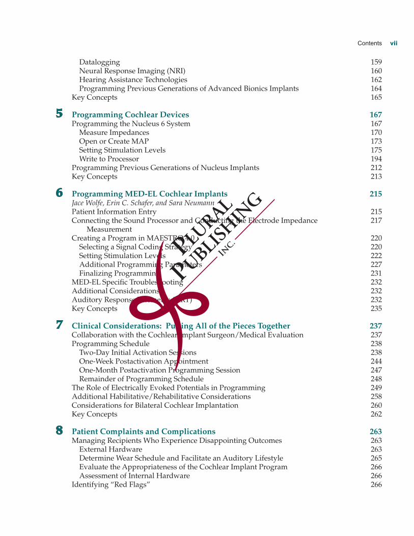
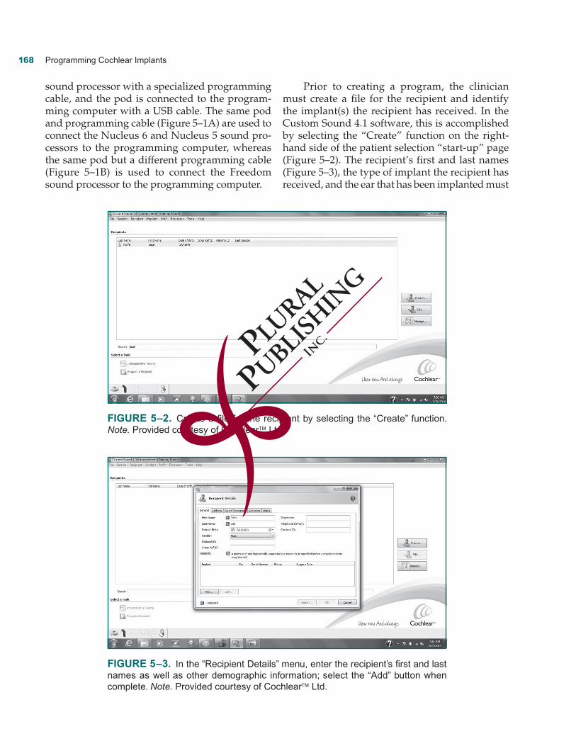
Prior to creating a program, the clinician must create a file for the recipient and identify the implant(s) the recipient has received. In the Custom Sound 4.1 software, this is accomplished by selecting the “Create” function on the right-hand side of the patient selection “start-up” page (Figure 5–2). The recipient’s first and last names (Figure 5–3), the type of implant the recipient has received, and the ear that has been implanted must
FigurE 5–2. Create a file for the recipient by selecting the “Create” function. Note. Provided courtesy of Cochlear™ Ltd.
FigurE 5–3. In the “Recipient Details” menu, enter the recipient’s first and last names as well as other demographic information; select the “Add” button when complete. Note. Provided courtesy of Cochlear™ Ltd.

Programming Cochlear Devices 169
be entered into the “Recipient Details” menu. Additional demographic information may also be entered as the clinician desires. The clinician must select the “Add” button in the “Recipient Details” menu to enter the implant the recipient has received (see Figure 5–3). A pop-up menu is provided, and from this menu, the clinician must enter the recipient implant model(s) and the ear(s) that was implanted (Figure 5–4).
In the Cochlear Custom Sound 4.1 software, the basic programming process is essentially divided into four categories (Figure 5–5): (1) Mea-sure Impedances, (2) Open or Create MAP, (3) Set Levels, and (4) Write to Processor. The clinician may choose to incorporate other steps into the process as needed. These additional steps include: Perform Neural Response Telemetry (NRT), Bilat-eral Balance, and Finalize Programming. The
FigurE 5–4. Pop-up menu for selection of the recipient implant model(s) and the ear(s) that was implanted. Note. Provided courtesy of Cochlear™ Ltd.
FigurE 5–5. Each programming task is shown in a box on the left side of the screen. Note. Provided courtesy of Cochlear™ Ltd.

170 Programming Cochlear Implants
following description of programming Cochlear devices will be organized to correspond with the aforementioned categories.
measure impedances
The first step involved in programming in Custom Sound 4.1 is to measure electrode impedance in four different electrode coupling modes. Electrode impedances are measured by simply selecting the “Measure” button within the “Measure Imped-ance” platform (Figure 5–6). The results of the measurement are promptly displayed in the illus-tration of the electrode array and reference elec-trodes by depicting impedances falling within the normal range in a green color and any abnormal findings in a red color (see Figure 5–6). The clini-cian should select the “Details” button to review to electrode impedances in graphical and tabular form (Figure 5–7).
In each electrode coupling mode, a low-level electrical current (100 CL with a pulse width of 25 usec), which is inaudible for most but not all recipients, is delivered sequentially to each intra-cochlear electrode contact. The impedance (in kOhms) is measured across the entire circuit as
the current travels from the current source to the intracochlear electrode contact and finally to one or more reference electrodes.
Impedance is first measured in the common ground mode where the low-level current is deliv-ered sequentially to each intracochlear electrode contact. Each of the remaining intracochlear con-tacts simultaneously serves as the return path. Because the common ground mode electrically couples each intracochlear electrode contact to the remaining intracochlear electrode contacts within the array, it is the most sensitive mode for detecting shorted electrode contacts. As a result, common ground is the preferred electrode coupling mode to detect anomalous intracochlear electrodes.
The Monopolar 1 and Monopolar 2 coupling modes measure electrode impedance by sequen-tially delivering the low-level current to each intracochlear electrode contact and by evaluat-ing the impedance in the circuit from the current source to each intracochlear electrode and extra-cochlear reference electrode. Measuring electrode impedance in the Monopolar 1 and Monopolar 2 modes allows the clinician to identify the status of the extracochlear reference electrodes (located on the end of the nonstimulating electrode lead and the implant case, respectively).
FigurE 5–6. Measuring impedances. Note. Electrodes 3, 4, and 12 are darkly shad- ed in this figure (abnormal impedance), whereas remaining electrodes are lightly shaded in this figure (normal impedance). Provided courtesy of Cochlear™ Ltd.

Programming Cochlear Devices 171
In the fourth mode, Monopolar 1+2, each intracochlear electrode is referenced to both the remote and case reference electrodes. In other words, the measure is completed by evaluating the impedance that exists in the circuit from the cur-rent source to each intracochlear electrode contact and finally to the reference, which is comprised of MP1 and MP2 which are electrically coupled to one another. The Monopolar 1+2 (MP1+2) mode is the default mode used for stimulation in the pri-mary signal coding strategy used with Cochlear devices, the Advanced Combination Encoder (ACE) signal coding strategy (also in the Continu-ous Interleaved Sampling [CIS] and Spectral-Peak [SPEAK] strategies). As a result, impedance mea-sured in the MP1+2 mode closely reflects the typi-cal impedance present during stimulation when the implant is used on a daily basis.
According to the manufacturer, electrode impedances below 565 ohms are abnormally low and are designated as “short” circuits, whereas electrode impedances greater than 30 kohms for half-band electrode contacts (e.g., Nucleus Free-dom, CI422, CI512, Hybrid) are abnormally high and are referred to as “open” circuits. It should be noted that the open circuit limit for the elec-trode array with full-band electrode contacts (e.g., Nucleus Straight Array and the Nucleus Double
Array) is 20 kOhms. Electrodes with abnormal impedances are typically “flagged” and deacti-vated for programming and subsequent imped-ance assessments. In the “Measure Impedance” module, “flagged” electrodes are depicted in yel-low for all subsequent impedance measurements. Flagged electrodes are also “grayed out” (dis-abled) in the programming/”Set Levels” module of Custom Sound.
At initial activation, impedance is frequently high but will generally decrease with routine implant use. Therefore, the clinician should reas-sess the impedance of electrodes with abnormally high electrode impedance to determine whether impedance decreases to normal levels after stim-ulation of the electrodes. However, shorted elec-trodes will typically always remain as shorted electrodes and should be permanently disabled once they are identified. It should be reiterated that shorted electrodes are identified not only by their abnormally low impedance (i.e., less than 565 ohms) but also because the common ground mode allows for detection of two or more intraco-chlear electrodes that are electrically connected to one another.
For situations in which an electrode initially had abnormal impedance prior to stimulation and was subsequently flagged, the clinician may
FigurE 5–7. After measuring impedances, select the “Details” button to review to electrode impedances in graphical and tabular form. Note. Provided courtesy of Cochlear™ Ltd.