Embed Size (px)
Citation preview
Since the manufacturer has a policy of continuous productimprovement, it reserves the right to change specifications anddesign without notice.
Programming CGAF-PTG-1TroubleshootingGuide
Library Service Literature
Product Section Refrigeration
Product Hermetic Scroll Liquid Chillers, Air Cooled
Model CGAF
Literature Type Programming, Trouble Shooting Guide
Sequence 1
Date September 1997
File No. SV-RF-CG-CGAF-PTG-1 9/97
Supersedes New
TM
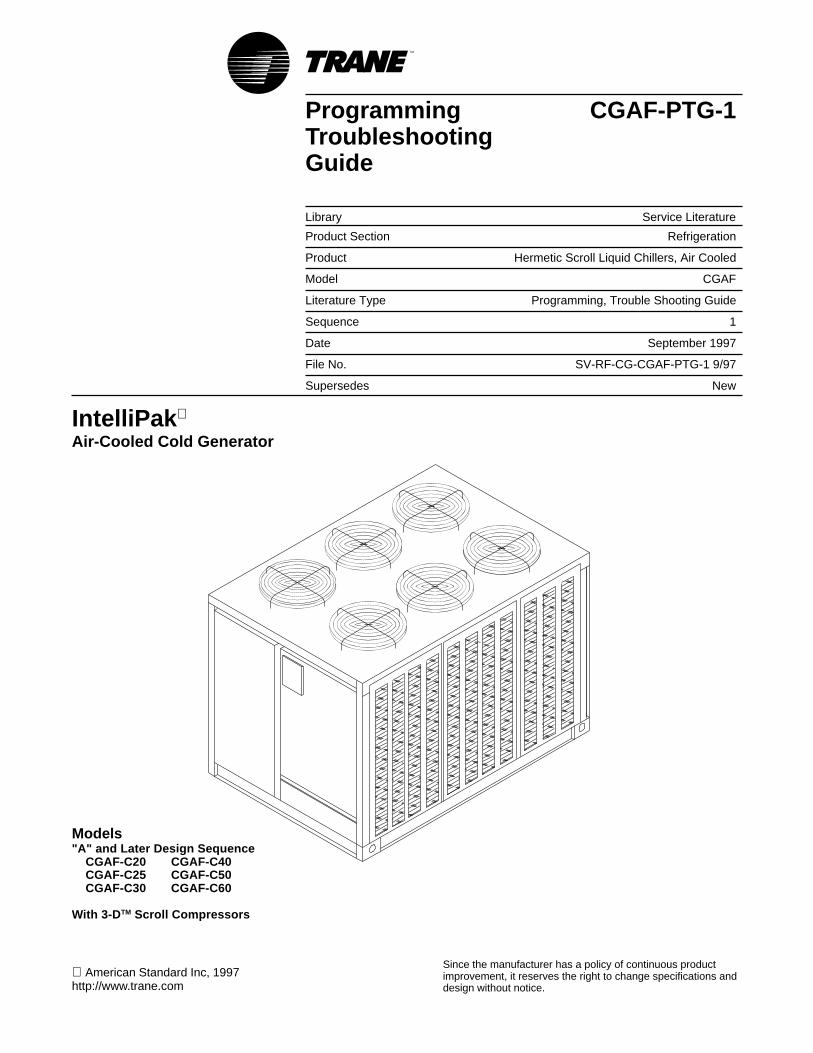
IntelliPak
Air-Cooled Cold Generator
Models"A" and Later Design Sequence CGAF-C20 CGAF-C40 CGAF-C25 CGAF-C50 CGAF-C30 CGAF-C60
With 3-D TM Scroll Compressors
American Standard Inc, 1997http://www.trane.com
2
About The ManualLiterature Change History
CGAF-PTG-1 (September 1993)Original issue of this manual; provides specific program-ming, diagnostic, and troubleshooting information CGAFunits with “A” and later design sequence.
Overview of Manual
Note: One copy of this document ships inside thecontrol panel of each unit and is customerproperty. It must be retained by the unit’smaintenance personnel.
These units are equipped with electronic control moduleswhich provides operating functions that are significantly dif-ferent than conventional units.
The manual is divided into 6 sections. Each section pro-vides the operator with specific information about the sys-tem operating parameters and their related screens. Bycarefully following the screen layout within this manualwhile scrolling through the Human Interface, the operatorcan monitor operating status, set specific operating param-eters, and diagnose system problems.
Before attempting to operate or service this equipment, re-fer to the “Start-Up” and “Test Mode” procedures in the ap-plicable Installation, Operation and Maintenance manual,listed on the unit nameplate.
Note: The procedures discussed in this manualshould only be performed by qualified, experiencedHVAC technicians.
Refer to the Table of Contents and Index for specific topicscontained in this manual and supporting manuals.
3
Table of ContentsManual Used with:
CGAF-IOM-1 (9/97)
Section OneAbout The Manual
Literature Change History ................................................ 2Overview of Manual ......................................................... 2
Section TwoGeneral Information
Model Number Description .............................................. 4Unit Nameplate ................................................................ 4Hazard Identification ........................................................ 4Commonly Used Acronyms ............................................. 4Glossary of Terms ............................................................ 5CGM Control System ....................................................... 6CGM Module .................................................................... 6Compressor Module ......................................................... 6Human Interface Module ................................................. 6Generic BAS Module ....................................................... 6Interprocessor Communications Bridge Module ............. 6Trane Communications Interface Module ........................ 6Power Disconnecting Switches ........................................ 6
Manual Disconnect Switch ........................................... 6115V Control Circuit Switch (1S1) ................................ 624 Transformer Switch (1S70) ..................................... 6
Human Interface Module ................................................. 7General Operation ........................................................ 7Menu Keys .................................................................... 8Data Manipulation Keys ............................................... 8Unit Operation Keys ..................................................... 9
General Status Display .................................................. 10Unit "Off" or "Stopped" ............................................... 10Unit "On" ..................................................................... 10No Configuration ........................................................ 10
Factory Presets .............................................................. 11Password Protected Screens ........................................ 14
Section ThreeSystem Operating Status
Status Menu ................................................................... 15
Section FourSystem Programming
Setup Menu .................................................................... 23Control Parameters .................................................... 23Actuator Operating Parameters ................................. 31Setpoint Menu ............................................................ 34
Section FiveSystem Configuration
Configuration Menu ........................................................ 36
Section SixSystem Testing & Troubleshooting
Service Mode Menu ....................................................... 39Diagnostic Menu ............................................................ 43Failure Modes ................................................................ 45Diagnostics ..................................................................... 45
Index .................................................................................. 46
4
General InformationModel Number Description
All Trane products are identified by a multiple-charactermodel number that precisely identifies a particular type ofunit. An explanation of the alphanumeric identification codeis provided below. Its use will enable the owner/operator, in-stalling contractors, and service engineers to define the op-
eration, specific components, and other options for any spe-cific unit.
When ordering replacement parts or requesting service, besure to refer to the specific model number, serial number,and DL number (if applicable) stamped on the unit name-plate.
Sample Model Number: CGAF - C30 4 A A B 0 D etc.Digit Number: 1,2,3,4 5,6,7 8 9 10 11 12 13 +
Digit 1,2 - Unit Function Digit 9 - Heating Capacity Digit 13, etc. MiscellaneousCG = Cold Generator A = Standard A = Communications Interface (TCI)
B = No Unit Heat Tape (50 Hz Units Only)Digit 3 - Unit Type Digit 10 - Design Sequence C = Compressor Current Sensing (CSM)A = Air-Cooled Condenser A = IntelliPak Controls D = Non-Fused Unit-Mounted Disconnect
E = *Unit Isolators - Neoprene P/SDigit 4 - Development Sequence Digit 11 - Leaving Water Setpoint F = *Unit Isolators - Spring P/SF = Sixth A = 40 - 50 F w/o Ice Machine G = Superheat / Subcooling
B = 30 - 39 F w/o Ice Machine H = Hot Gas BypassDigit 5,6,7 - Nominal Capacity D = 51 - 65 F w/o Ice Machine J = Generic BAS Module 0-5 VDC Input, Binary O.PC20 = 20 Tons E = 20 - 29 F w/o Ice Machine K = Stock UnitC25 = 25 Tons 1 = 40 - 50 F w Ice Machine M = *Remote Human InterfaceC30 = 30 Tons 2 = 30 - 39 F w Ice Machine N = Generic BAS Module 0-10 VDC Analog OutputC40 = 40 Tons 3 = 51 - 65 F w Ice Machine P = Remote Setpoint Potentiometer P/SC50 = 50 Tons 4 = 20 - 29 F w Ice Machine Q = *Zone Sensor (Chilled Solution Reset) P/S C60 = 60 Tons S = Special R = Phase / Voltage Monitoring
S = SpecialDigit 8 - Power Supply Digit 12 - Agency Approval T = *Flow Switch P/SE = 200/60/3 P/S*** 0 = None V = Copper Fin Condenser Coil F = 230/60/3 P/S*** 1 = UL/CSA W = **Electronic Low Ambient Dampers P/S 4 = 460/60/3 P/S*** Y = *Inter-Processor Comm Bridge (IPCB)5 = 575/50/3 9 = Packed Stock Unit9 = 380/50/3 * = Field Installed OptionsD = 415/50/3 ** = Factory or Field Installed OptionS = Special *** Available on Pack Stock Units
Unit NameplateOne Mylar unit nameplate is located on the outside upperleft corner of the control panel door. It includes the unitmodel number, serial number, electrical characteristics,weight, refrigerant charge, as well as other pertinent unitdata. A small metal nameplate with the Model Number, Se-rial Number, and Unit Weight is located just above the Mylarnameplate, and a third nameplate is located on the inside ofthe control panel door.
Hazard Identification
Warnings are provided throughout this manual to indicate toinstalling contractors, operators, and service personnel ofpotentially hazardous situations which, if not avoided,COULD result in death or serious injury.
Cautions are provided throughout this manual to indicate toinstalling contractors, operators, and service personnel ofpotentially hazardous situations which, if not avoided, MAYresult in minor or moderate injury.
Commonly Used Acronyms
For convenience, a number of acronyms and abbreviationsare used throughout this manual. These acronyms are al-phabetically listed and defined below.
A/D = Analog/DigitalBAS = Building Automation SystemCAR = Circuit shuwdown - Auto ResetCf = Evaporator limit control integratorCGA = Air cooled - Cold GeneratorCGM = Cold generator module. Contains I/O for most
chilled solution functions.Comp(s) = compressor(s)Cond = condenserCkt = circuitCLE = Chilled solution flow integratorCMR = Circuit shutdown - Manual ResetCRS = Control response setpointCSA = Canadian Standards AssociationCCW = counterclockwiseCW = clockwiseDBZ = Width of Dead Band ZoneDDT = Design Delta-T setpointDelta T = The temperature difference between EST & LSTDiag = diagnosticsEST = Entering solution temperatureEnt = Entering
5
General InformationEvap = EvaporatorExt = ExternalGBAS = Generic Building Automation System Modulegfm = gallons per minuteHGBP = Hot gas bypassHI = Human InterfaceHO = History OnlyHSLLS = Hot Start Load Limit setpointHVAC = Heating, Ventilation and Air ConditioningI/O = Inputs/outputsIAR = Information only Auto ResetIBTS = Ice Build Terminate SetpointICS = Integrated Comfort SystemIFW = Informational WarningIOM = installation/operation/maintenance manualIPC = Interprocessor communicationsIPCB Module = Interprocessor communicatons bridge mod-
uleIRDT = Ice Rebuild Delay TimerLCD = Liquid Crystal DisplayLED = Light Emitting DiodeLH = left-handLLSC = Low Leaving Solution Temperature Cutout SetpointLPC = Low Pressure Control SwitchLST = Leaving solution temperatureMAR = Machine shutdown - Auto ResetMax = maximumMCM = Multiple circuit compressor moduleMin = minimumMisc = miscellaneousMMR = Machine shutdown - Manual ResetMod = moduleMon = monitorNCS = Number of capacity stepsnum = numberOA = Outdoor airOAT = Outdoor air TemperaturePRT = Pump Run TimerPSIG = pounds-per-square-inch gauge pressurePWM = Pulse width modulatedRAM = Random Access MemoryRTM = rooftop moduleROM = Read Only MemoryS/W = SoftwareSat - saturatedSCM = single circuit compressor moduleSCT = Saturated Condensing TemperatureSoln = solutionSTP = setpointTCI Module = Trane communications interface moduleTemp = temperatureUCM = Unit Control ModulesUL = Underwriter's LaboratoriesVFD = Variable Frequency Drivew.c. = water columnXL = across-the-line start
Glossary of Terms
Carefully review these definitions since they are usedthroughout this document and the I.O.M.. Knowledge ofthese terms is essential in gaining an understanding of howthese units operate.
Active SetpointThe setpoint which is currently being used for control bythe setpoint source selection.
Chilled Solution Temperature ResetA function that shifts the Leaving Solution Temp Setpointan amount based on the value of another parameter—typically ZoneTemp, Entering Solution Temp or OutdoorAir Temp. The purpose of this function is to lower unit ca-pacity to better meet load requirements.
Compressor Protection SwitchA pressure switch installed on the suction line that pre-vents compressor operation below the switch's setpoint.
Control BandThe range of temperatures or pressures which wouldnormally be maintained by the various control functions.
Control PointThe value of a setpoint that an algorithm is using at anygiven time.
DeadbandAs applied to LST control, this refers to a range of tem-peratures equally spaced above and below the CSS inwhich the control algorithm is satisfied. There is not ad-justment of machine capacity within the deadband.
Emergency StopCGM binary input. Can be used for emergency shutdownof the unit by field-installed contacts. A diagnostic is pro-duced when this input is open.
External Auto/StopA binary input on the CGM that allows the use of a field-supplied switch to perform normal unit on/off action.
Leaving Solution SetpointActive leaving solution setpoint. This setpoint is the con-trol setpoint for process and comfort cooling.
Leaving Solution Temperature Control PointThe revised temperature setpoint after chilled solutiontemp reset has been applied.
Low Ambient Compressor LockoutA function which prevents compressor operation at lowoutdoor ambient temperatures.
Remote Human InterfaceA human interface module designed to be mounted re-motely from the unit. There will be some functional differ-ences between a unit mounted and a remote mountedhuman interface module.
Reset Amount MaximumThe maximum amount of reset allowed.
Reset End TemperatureThe temperature at which the maximum reset amountwill occur.
Reset Start TemperatureThe temperature at which reset will begin.
Unit Control ModuleThis term is used to describe the set of electronic mod-ules which make up the unit control system.
6
General InformationCGM Control System
Trane Large Commercial Cold Generator Units are con-trolled by a microelectronic control system that consists of anetwork of modules and are refered to as Cold GeneratorModules (CGM).
The unit size, peripheral devices, options, etc... determinethe number and type of modules that a particular unit mayemploy.
The CGM receives analog and binary inputs, then pro-cesses this information and supplies outputs in the form ofmodulating voltages, contact closures, etc... to controldamper actuators, fan motors, compressors, valves, andother electrical devices in the system to maintain set tem-perature levels.
The CGM provides some equipment protection functionsboth directly and indirectly, such as chilled water flow andcompressor lockouts.
Listed below are the various modules that may be em-ployed in a CGM control system.
Cold Generator Module (CGM - Standard)The Cold Generator Module (CGM) responds to cooling re-quests by energizing the proper unit components based oninformation received from other unit modules, sensors, re-mote panels, and customer supplied binary inputs. It ini-tiates unit operation based on that information.
Compressor Module (SCM & MCM - Size Specific)The Compressor module, (Single Circuit & Multiple Circuit),upon receiving a request for mechanical cooling, energizesthe appropriate compressors and condenser fans. It moni-tors the compressor operation through feedback informationit receives from various protection devices.
Interprocessor Communications Board(IPCB - used with Optional Remote Human Interface)The Interprocessor Communication Board expands commu-nications from the unit’s UCM network to a Remote HumanInterface Panel. DIP switch settings on the IPCB module forthis application should be; Switches 1 and 2 “Off”, Switch 3“On”.
Trane Communications Interface Module (TCI)(Optional - used with Trane ICS TM Systems)The Trane Communication Interface module allows externalsetpoints for most of the unit functions to be communicatedto the unit’s UCM network via a Trane ICSTM system or aSummitTM Tracer system. DIP Switch settings on the TCImodule for these applications should be; Switches 1, 2, and3 are “Off”.
Generic Building Automation System Module (GBAS)(Optional - used with Non-Trane Building ControlSystem)The Generic Building Automation System (GBAS) moduleallows a non-Trane building control system to communicatewith the unit and accepts external setpoints in form of ana-log inputs (0 - 5 DCV or 0 - 10 DCV depending on the mod-ule selected) and a binary Input for demand limit. Five (5)binary outputs are available on 0 - 5 DCV modules. One (1)binary output and four (4) analog outputs are available onthe 0 - 10 DCV modules. Refer to the “Field Installed Con-trol Wiring” section for the control wiring to the GBAS mod-ule and the various desired setpoints with the correspond-ing DC voltage inputs.
Current Sensing Module (CSM - Optional)Current transformers located around two (2) of the mainpower leads for each compressor monitors the running cur-rent during compressor operation. The information is sent tothe CGM and can be accessed through the “CompressorStatus” submenu displayed at the Human Interface Module.
Superheat & Subcooling Module (SSM - Optional)Monitors the system operating superheat and subcoolingthrough the use of pressure transducers, liquid line, andsuction line temperature sensors. The information is sent tothe SSM and can be accessed through the “CompressorStatus” submenu displayed at the Human Interface Module.
Power Disconnecting Switches
Manual Disconnect Switch(Optional 1S14) Manual disconnect switch 1S14, located inthe unit control panel, instead of the power terminal block1TB1, allows the operator to disconnect power from theunit's “high” voltage (200V-575V) section, the 115V section,and the 24V section without having to open the controlpanel door. A description of its features and operation aregiven in the Installation, Operation, & Maintanence manual.
115V Control Circuit Switch (1S1)Control circuit switch (1S1) is provided on all units and is lo-cated downstream of the 115V transformer 1T1. It allowsthe operator to disconnect power from the unit's 115V con-trol components by placing the switch in the "Off" position.
24V Transformer Switch (1S70)Transformer switch 1S70 is provided on all units and is lo-cated downstream of 24V transformers 1T2 and 1T3. It al-lows the operator to disconnect (24V) power from all of theunit's control modules by placing the switch in the "Off" po-sition.
For a complete description of the 24V components and op-eration, refer to the latest edition of the applicable Installa-tion, Operation and Maintenance manual listed on the unitnameplate.
7
General InformationGeneral Operation
At power-up, the Human Interface LCD will display one ofthree initial screens illustrated in the "General Status" sec-tion.
1. Unit Status (Unit Off or Stopped) (The unit is configuredand operational, but is not running). This screen showsstate, mode, and function information when the unit is offor stopped.
2. Unit Status (Unit On) (The unit is configured and opera-tional, and is running). This screen shows state, mode,and function information when the unit is on.
3. No Configuration (the unit needs to be configured). Thisscreen shows that required configuration data is missing.
The LCD screen has a backlight that makes the informationeasier to read. The light will go out if no keys are pressedfor 30 minutes. If it goes out, simply press the STATUS key.
Human Interface Module
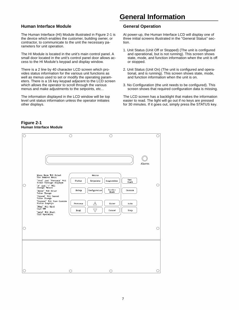
The Human Interface (HI) Module illustrated in Figure 2-1 isthe device which enables the customer, building owner, orcontractor, to communicate to the unit the necessary pa-rameters for unit operation.
The HI Module is located in the unit’s main control panel. Asmall door located in the unit’s control panel door allows ac-cess to the HI Module’s keypad and display window.
There is a 2 line by 40 character LCD screen which pro-vides status information for the various unit functions aswell as menus used to set or modify the operating param-eters. There is a 16 key keypad adjacent to the LCD screenwhich allows the operator to scroll through the variousmenus and make adjustments to the setpoints, etc...
The information displayed in the LCD window will be toplevel unit status information unless the operator initiatesother displays.
Figure 2-1Human Interface Module
8
General InformationMenu Keys
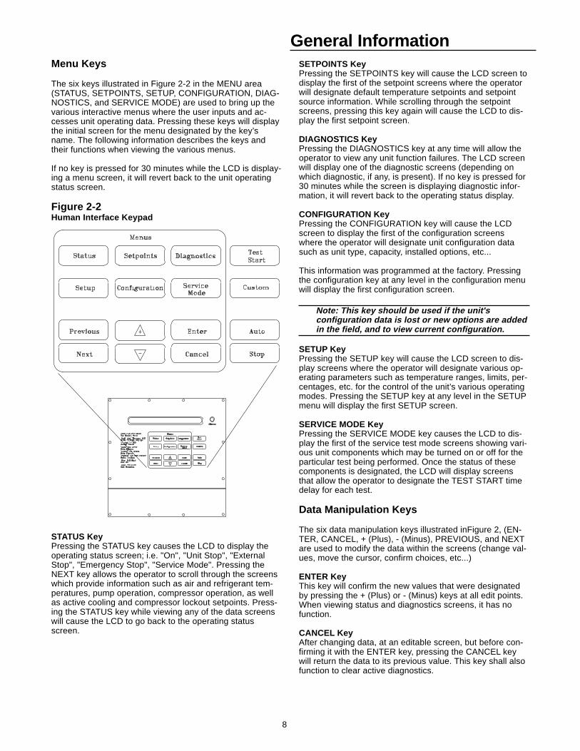
The six keys illustrated in Figure 2-2 in the MENU area(STATUS, SETPOINTS, SETUP, CONFIGURATION, DIAG-NOSTICS, and SERVICE MODE) are used to bring up thevarious interactive menus where the user inputs and ac-cesses unit operating data. Pressing these keys will displaythe initial screen for the menu designated by the key’sname. The following information describes the keys andtheir functions when viewing the various menus.
If no key is pressed for 30 minutes while the LCD is display-ing a menu screen, it will revert back to the unit operatingstatus screen.
Figure 2-2Human Interface Keypad
STATUS KeyPressing the STATUS key causes the LCD to display theoperating status screen; i.e. "On", "Unit Stop", "ExternalStop", "Emergency Stop", "Service Mode". Pressing theNEXT key allows the operator to scroll through the screenswhich provide information such as air and refrigerant tem-peratures, pump operation, compressor operation, as wellas active cooling and compressor lockout setpoints. Press-ing the STATUS key while viewing any of the data screenswill cause the LCD to go back to the operating statusscreen.
SETPOINTS KeyPressing the SETPOINTS key will cause the LCD screen todisplay the first of the setpoint screens where the operatorwill designate default temperature setpoints and setpointsource information. While scrolling through the setpointscreens, pressing this key again will cause the LCD to dis-play the first setpoint screen.
DIAGNOSTICS KeyPressing the DIAGNOSTICS key at any time will allow theoperator to view any unit function failures. The LCD screenwill display one of the diagnostic screens (depending onwhich diagnostic, if any, is present). If no key is pressed for30 minutes while the screen is displaying diagnostic infor-mation, it will revert back to the operating status display.
CONFIGURATION KeyPressing the CONFIGURATION key will cause the LCDscreen to display the first of the configuration screenswhere the operator will designate unit configuration datasuch as unit type, capacity, installed options, etc...
This information was programmed at the factory. Pressingthe configuration key at any level in the configuration menuwill display the first configuration screen.
Note: This key should be used if the unit'sconfiguration data is lost or new options are addedin the field, and to view current configuration.
SETUP KeyPressing the SETUP key will cause the LCD screen to dis-play screens where the operator will designate various op-erating parameters such as temperature ranges, limits, per-centages, etc. for the control of the unit’s various operatingmodes. Pressing the SETUP key at any level in the SETUPmenu will display the first SETUP screen.
SERVICE MODE KeyPressing the SERVICE MODE key causes the LCD to dis-play the first of the service test mode screens showing vari-ous unit components which may be turned on or off for theparticular test being performed. Once the status of thesecomponents is designated, the LCD will display screensthat allow the operator to designate the TEST START timedelay for each test.
Data Manipulation Keys
The six data manipulation keys illustrated inFigure 2, (EN-TER, CANCEL, + (Plus), - (Minus), PREVIOUS, and NEXTare used to modify the data within the screens (change val-ues, move the cursor, confirm choices, etc...)
ENTER KeyThis key will confirm the new values that were designatedby pressing the + (Plus) or - (Minus) keys at all edit points.When viewing status and diagnostics screens, it has nofunction.
CANCEL KeyAfter changing data, at an editable screen, but before con-firming it with the ENTER key, pressing the CANCEL keywill return the data to its previous value. This key shall alsofunction to clear active diagnostics.
9
General Informationate mode no matter what level in the menu structure is cur-rently being displayed. If the current display is an editabledisplay, the AUTO key will confirm the desired edit.
STOP KeyPressing the STOP key will cause the unit to transition tothe stop state. If the current display is editable, pressing theSTOP key will cancel the desired edit.
TEST START Key (SERVICE)Pressing this key while viewing any screen in the SERVICEMode menu will start the service test. When viewing status,setup, setpoint, and diagnostics screens, it has no function.
CUSTOM KeyThe Custom menu is simply a status menu that containsscreens that the user monitors most frequently. The Custommenu can only contain five status screens. To create theCustom menu, press the STATUS key, followed by theNEXT key (this brings up the initial status screen). If youwant to add this screen to the Custom menu, press the +(Plus) key, if not, press the Next key again until a statusscreen appears that you would like to add to the Custommenu. Pressing the + (Plus) key while viewing any of thevarious status screens will add that screen to the Custommenu. Once the Custom menu is programed it can be ac-cessed by pressing the CUSTOM key. To remove a statusscreen from the Custom menu, press the CUSTOM key,then press the NEXT key until the status screen that youwant to remove appears, then press the - (Minus) key.
+ (Plus) KeyWhen viewing a setpoint screen, this key will increase thetemperature or pressure value of the setpoint. When work-ing with a status menu, it will add the current status displayto the custom menu. When viewing the setup or service testscreens, it will increase setpoints or toggle choices On orOff at each edit point.
- (Minus) KeyThis key when viewing the setpoint screen will decrease thetemperature or pressure value of the setpoint. When view-ing the setup or service test screens, it will decreasesetpoints or toggle choices On or Off at each edit point.When viewing the custom menu, pressing the - (Minus) keywill remove the status screen from the custom menu. Whenviewing diagnostics screens it has no function.
PREVIOUS KeyPressing the PREVIOUS key causes the LCD to scrollbackwards through the various displays for each menu. Atdisplays with multiple edit points, it moves the cursor fromone edit point to another.
NEXT KeyPressing the NEXT key causes the LCD to scroll forwardthrough the various displays for each menu. At displayswith multiple edit points it moves the cursor from one editpoint to another.
Unit Operation Keys
AUTO KeyPressing the AUTO key at any time will cause the display togo to the top level status display and, if the unit is shut-down, will cause the unit to begin operation in the appropri-
10
General InformationGeneral Status Display
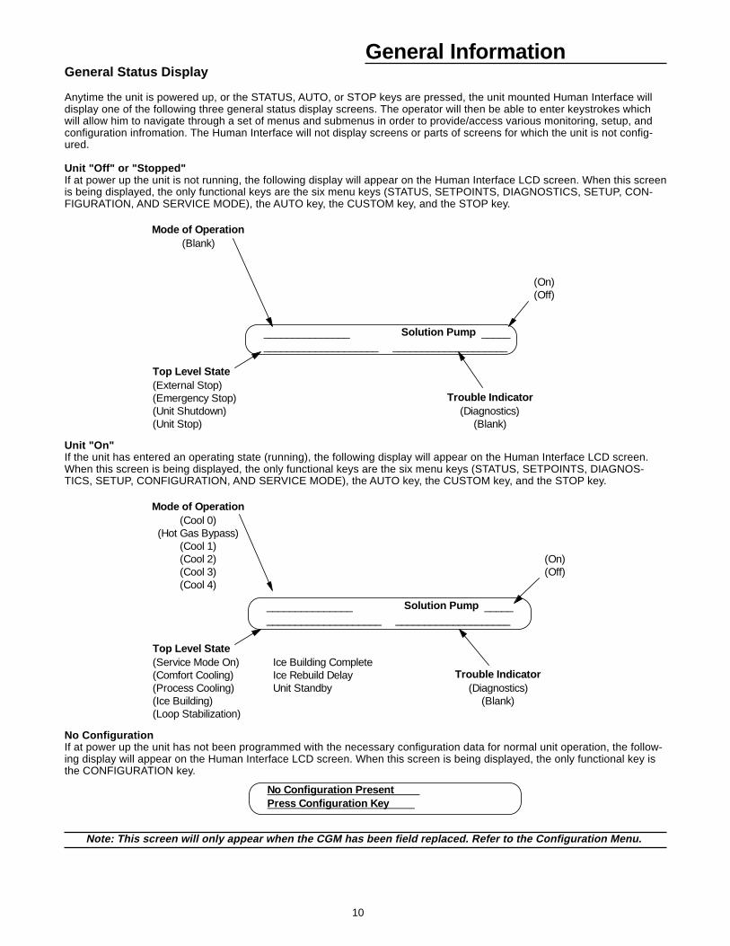
Anytime the unit is powered up, or the STATUS, AUTO, or STOP keys are pressed, the unit mounted Human Interface willdisplay one of the following three general status display screens. The operator will then be able to enter keystrokes whichwill allow him to navigate through a set of menus and submenus in order to provide/access various monitoring, setup, andconfiguration infromation. The Human Interface will not display screens or parts of screens for which the unit is not config-ured.
Unit "Off" or "Stopped"If at power up the unit is not running, the following display will appear on the Human Interface LCD screen. When this screenis being displayed, the only functional keys are the six menu keys (STATUS, SETPOINTS, DIAGNOSTICS, SETUP, CON-FIGURATION, AND SERVICE MODE), the AUTO key, the CUSTOM key, and the STOP key.
Mode of Operation(Blank)
(On)(Off)
Top Level State(External Stop)(Emergency Stop) Trouble Indicator(Unit Shutdown) (Diagnostics)(Unit Stop) (Blank)
_______________ Solution Pump _____ ____________________ ____________________
Unit "On"If the unit has entered an operating state (running), the following display will appear on the Human Interface LCD screen.When this screen is being displayed, the only functional keys are the six menu keys (STATUS, SETPOINTS, DIAGNOS-TICS, SETUP, CONFIGURATION, AND SERVICE MODE), the AUTO key, the CUSTOM key, and the STOP key.
Mode of Operation(Cool 0)
(Hot Gas Bypass)(Cool 1)(Cool 2) (On)(Cool 3) (Off)(Cool 4)
Top Level State(Service Mode On) Ice Building Complete(Comfort Cooling) Ice Rebuild Delay Trouble Indicator(Process Cooling) Unit Standby (Diagnostics)(Ice Building) (Blank)(Loop Stabilization)
_______________ Solution Pump _____ ____________________ ____________________
No ConfigurationIf at power up the unit has not been programmed with the necessary configuration data for normal unit operation, the follow-ing display will appear on the Human Interface LCD screen. When this screen is being displayed, the only functional key isthe CONFIGURATION key.
No Configuration Present Press Configuration Key
Note: This screen will only appear when the CGM has been field replaced. Refer to the Configuration Menu.
11
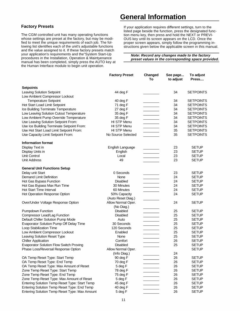
General InformationFactory Presets
The CGM controlled unit has many operating functionswhose settings are preset at the factory, but may be modi-fied to meet the unique requirements of each job. The fol-lowing list identifies each of the unit's adjustable functionsand the value assigned to it. If these factory presets matchyour application's requirements and the"System Start-Upprocedures in the Installation, Operation & Maintyenancemanual has been completed, simply press the AUTO key atthe Human Interface module to begin unit operation.
If your application requires different settings, turn to thelisted page beside the function, press the designated func-tion menu key, then press and hold the NEXT or PREVI-OUS key until its screen appears on the LCD. Once theproper screen appears, simply follow the programming in-structions given below the applicable screen in this manual.
Note: Record any changes made to the factorypreset values in the corresponding space provided.
Factory Preset Changed See page... To adjustTo to adjust Press....
SetpointsLeaving Solution Setpoint 44 deg F 34 SETPOINTSLow Ambient Compressor Lockout Temperature Setpoint 40 deg F 34 SETPOINTSHot Start Load Limit Setpoint 71 deg F 34 SETPOINTSIce Building Terminate Temperature 27 deg F 34 SETPOINTSLow Leaving Solution Cutout Temperature 35 deg F 34 SETPOINTSLow Ambient Pump Override Temperature 35 deg F 34 SETPOINTSUse Leaving Solution Setpoint From: HI STP Menu 34 SETPOINTSUse Ice Building Terminate Setpoint From: HI STP Menu 34 SETPOINTSUse Hot Start Load Limit Setpoint From: HI STP Menu 35 SETPOINTSUse Capacity Limit Setpoint From: No Source Selected 35 SETPOINTS
Information formatDisplay Text in English Language 23 SETUPDisplay Units in English 23 SETUPUnit Control Local 23 SETUPUnit Address 49 23 SETUP
General Unit Functions SetupDelay unit Start 0 Seconds 23 SETUPDemand Limit Definition None 24 SETUPHot Gas Bypass Function Disabled 24 SETUPHot Gas Bypass Max Run Time 30 Minutes 24 SETUPHot Start Time Interval 60 Minutes 24 SETUPHot Operation Response Option 50% Capacity 24 SETUP
(Auto Reset Diag.)Over/Under Voltage Response Option Allow Normal Oper. 24 SETUP
(No Diag.)Pumpdown Function Disabled 25 SETUPCompressor Lead/Lag Function Disabled 25 SETUPDefault Chiller Solution Pump Mode Auto 25 SETUPEvaporator Solution Pump Off Delay Time 30 Seconds 25 SETUPLoop Stabilization Time 120 Seconds 25 SETUPLow Ambient Compressor Lockout Enabled 25 SETUPLeaving Solution Reset Type None 25 SETUPChiller Application Comfort 26 SETUPEvaporator Solution Flow Switch Proving Disabled 25 SETUPPhase Loss/Reversal Response Option Allow Normal Oper. SETUP
(Info Diag.) 24OA Temp Reset Type: Start Temp 90 deg F 26 SETUPOA Temp Reset Type: End Temp 70 deg F 26 SETUPOA Temp Reset Type: Max Amount of Reset 5 deg F 26 SETUPZone Temp Reset Type: Start Temp 78 deg F 26 SETUPZone Temp Reset Type: End Temp 75 deg F 26 SETUPZone Temp Reset Type: Max Amount of Reset 5 deg F 26 SETUPEntering Solution Temp Reset Type: Start Temp 45 deg F 26 SETUPEntering Solution Temp Reset Type: End Temp 40 deg F 26 SETUPEntering Solution Temp Reset Type: Max Amount 5 deg F 26 SETUP
12
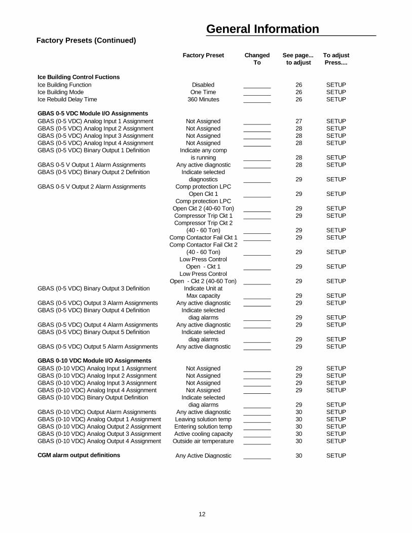
General InformationFactory Presets (Continued)
Factory Preset Changed See page... To adjustTo to adjust Press....
Ice Building Control FuctionsIce Building Function Disabled 26 SETUPIce Building Mode One Time 26 SETUPIce Rebuild Delay Time 360 Minutes 26 SETUP
GBAS 0-5 VDC Module I/O AssignmentsGBAS (0-5 VDC) Analog Input 1 Assignment Not Assigned 27 SETUPGBAS (0-5 VDC) Analog Input 2 Assignment Not Assigned 28 SETUPGBAS (0-5 VDC) Analog Input 3 Assignment Not Assigned 28 SETUPGBAS (0-5 VDC) Analog Input 4 Assignment Not Assigned 28 SETUPGBAS (0-5 VDC) Binary Output 1 Definition Indicate any comp
is running 28 SETUPGBAS 0-5 V Output 1 Alarm Assignments Any active diagnostic 28 SETUPGBAS (0-5 VDC) Binary Output 2 Definition Indicate selected
diagnostics 29 SETUPGBAS 0-5 V Output 2 Alarm Assignments Comp protection LPC
Open Ckt 1 29 SETUPComp protection LPC
Open Ckt 2 (40-60 Ton) 29 SETUPCompressor Trip Ckt 1 29 SETUPCompressor Trip Ckt 2
(40 - 60 Ton) 29 SETUPComp Contactor Fail Ckt 1 29 SETUPComp Contactor Fail Ckt 2
(40 - 60 Ton) 29 SETUPLow Press Control
Open - Ckt 1 29 SETUPLow Press Control
Open - Ckt 2 (40-60 Ton) 29 SETUPGBAS (0-5 VDC) Binary Output 3 Definition Indicate Unit at
Max capacity 29 SETUPGBAS (0-5 VDC) Output 3 Alarm Assignments Any active diagnostic 29 SETUPGBAS (0-5 VDC) Binary Output 4 Definition Indicate selected
diag alarms 29 SETUPGBAS (0-5 VDC) Output 4 Alarm Assignments Any active diagnostic 29 SETUPGBAS (0-5 VDC) Binary Output 5 Definition Indicate selected
diag alarms 29 SETUPGBAS (0-5 VDC) Output 5 Alarm Assignments Any active diagnostic 29 SETUP
GBAS 0-10 VDC Module I/O AssignmentsGBAS (0-10 VDC) Analog Input 1 Assignment Not Assigned 29 SETUPGBAS (0-10 VDC) Analog Input 2 Assignment Not Assigned 29 SETUPGBAS (0-10 VDC) Analog Input 3 Assignment Not Assigned 29 SETUPGBAS (0-10 VDC) Analog Input 4 Assignment Not Assigned 29 SETUPGBAS (0-10 VDC) Binary Output Definition Indicate selected
diag alarms 29 SETUPGBAS (0-10 VDC) Output Alarm Assignments Any active diagnostic 30 SETUPGBAS (0-10 VDC) Analog Output 1 Assignment Leaving solution temp 30 SETUPGBAS (0-10 VDC) Analog Output 2 Assignment Entering solution temp 30 SETUPGBAS (0-10 VDC) Analog Output 3 Assignment Active cooling capacity 30 SETUPGBAS (0-10 VDC) Analog Output 4 Assignment Outside air temperature 30 SETUP
CGM alarm output definitions Any Active Diagnostic 30 SETUP
13
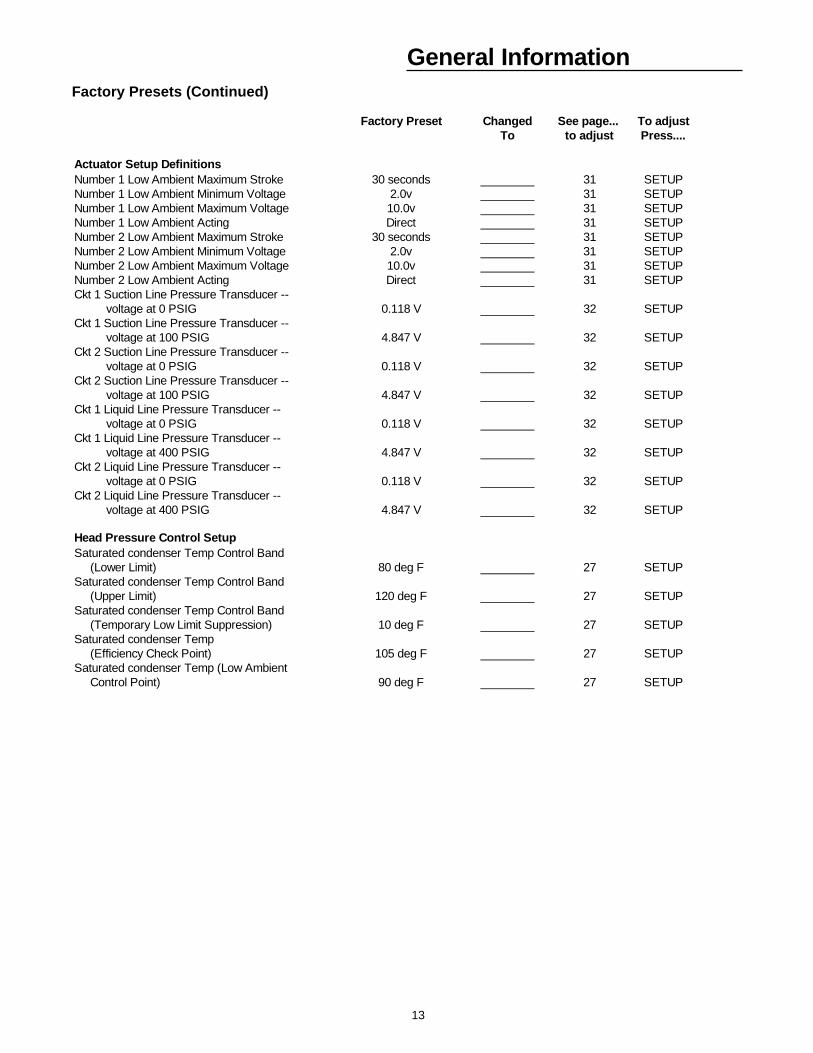
General InformationFactory Presets (Continued)
Factory Preset Changed See page... To adjustTo to adjust Press....
Actuator Setup DefinitionsNumber 1 Low Ambient Maximum Stroke 30 seconds 31 SETUPNumber 1 Low Ambient Minimum Voltage 2.0v 31 SETUPNumber 1 Low Ambient Maximum Voltage 10.0v 31 SETUPNumber 1 Low Ambient Acting Direct 31 SETUPNumber 2 Low Ambient Maximum Stroke 30 seconds 31 SETUPNumber 2 Low Ambient Minimum Voltage 2.0v 31 SETUPNumber 2 Low Ambient Maximum Voltage 10.0v 31 SETUPNumber 2 Low Ambient Acting Direct 31 SETUPCkt 1 Suction Line Pressure Transducer -- voltage at 0 PSIG 0.118 V 32 SETUPCkt 1 Suction Line Pressure Transducer -- voltage at 100 PSIG 4.847 V 32 SETUPCkt 2 Suction Line Pressure Transducer -- voltage at 0 PSIG 0.118 V 32 SETUPCkt 2 Suction Line Pressure Transducer -- voltage at 100 PSIG 4.847 V 32 SETUPCkt 1 Liquid Line Pressure Transducer -- voltage at 0 PSIG 0.118 V 32 SETUPCkt 1 Liquid Line Pressure Transducer -- voltage at 400 PSIG 4.847 V 32 SETUPCkt 2 Liquid Line Pressure Transducer -- voltage at 0 PSIG 0.118 V 32 SETUPCkt 2 Liquid Line Pressure Transducer -- voltage at 400 PSIG 4.847 V 32 SETUP
Head Pressure Control SetupSaturated condenser Temp Control Band (Lower Limit) 80 deg F 27 SETUPSaturated condenser Temp Control Band (Upper Limit) 120 deg F 27 SETUPSaturated condenser Temp Control Band (Temporary Low Limit Suppression) 10 deg F 27 SETUPSaturated condenser Temp (Efficiency Check Point) 105 deg F 27 SETUPSaturated condenser Temp (Low Ambient Control Point) 90 deg F 27 SETUP
14
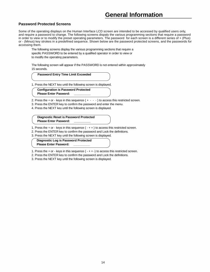
General InformationPassword Protected Screens
Some of the operating displays on the Human Interface LCD screen are intended to be accessed by qualified users only,and require a password to change. The following screens dispaly the various programming sections that require a passwordin order to view or to modify the preset operating parameters. The password for each screen is a different series of + (Plus)or - (Minus) key strokes in a predefined sequence. Shown below are the password protected screens, and the passwords foraccessing them.
The following screens display the various programming sections that require aspecific PASSWORD to be entered by a qualified operator in order to view or to modify the operating parameters.
The following screen will appear if the PASSWORD is not entered within approximately 15 seconds.
1. Press the NEXT key until the following screen is displayed.
2. Press the + or - keys in this sequence ( + - - - ) to access this restricted screen.3. Press the ENTER key to confirm the password and enter the menu.4. Press the NEXT key until the following screen is displayed.
1. Press the + or - keys in this sequence ( - + + ) to access this restricted screen.2. Press the ENTER key to confirm the password and Lock the definitions.3. Press the NEXT key until the following screen is displayed.
1. Press the + or - keys in this sequence ( - + + -) to access this restricted screen.2. Press the ENTER key to confirm the password and Lock the definitions.3. Press the NEXT key until the following screen is displayed.
Password Entry Time Limit Exceeded
Configuration is Password Protected Please Enter Pasword: __________
Diagnostic Reset is Password Protected Please Enter Pasword: __________
Diagnostic Log is Password Protected Please Enter Pasword: __________
15
System Operating StatusSTATUS Menu
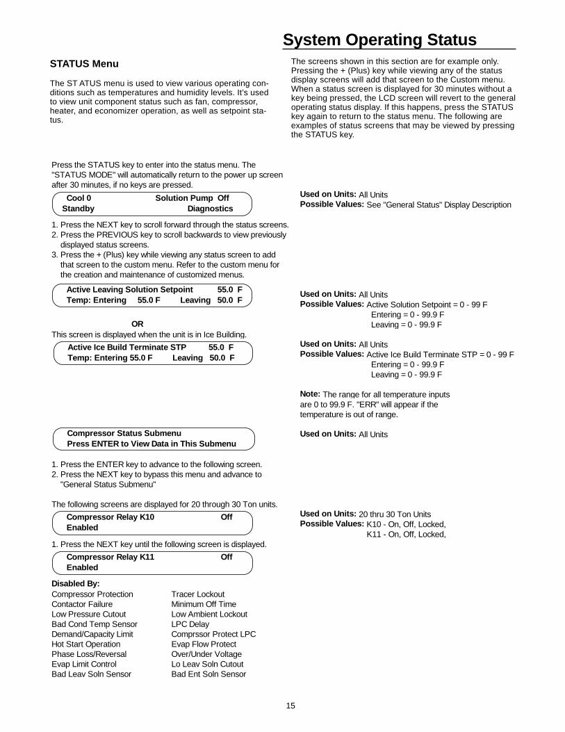
The ST ATUS menu is used to view various operating con-ditions such as temperatures and humidity levels. It’s usedto view unit component status such as fan, compressor,heater, and economizer operation, as well as setpoint sta-tus.
The screens shown in this section are for example only.Pressing the + (Plus) key while viewing any of the statusdisplay screens will add that screen to the Custom menu.When a status screen is displayed for 30 minutes without akey being pressed, the LCD screen will revert to the generaloperating status display. If this happens, press the STATUSkey again to return to the status menu. The following areexamples of status screens that may be viewed by pressingthe STATUS key.
Press the STATUS key to enter into the status menu. The"STATUS MODE" will automatically return to the power up screenafter 30 minutes, if no keys are pressed.
Used on Units: All UnitsPossible Values: See "General Status" Display Description
1. Press the NEXT key to scroll forward through the status screens.2. Press the PREVIOUS key to scroll backwards to view previously displayed status screens. 3. Press the + (Plus) key while viewing any status screen to add that screen to the custom menu. Refer to the custom menu for the creation and maintenance of customized menus.
Used on Units: All UnitsPossible Values: Active Solution Setpoint = 0 - 99 F Entering = 0 - 99.9 F
OR Leaving = 0 - 99.9 FThis screen is displayed when the unit is in Ice Building.
Used on Units: All UnitsPossible Values: Active Ice Build Terminate STP = 0 - 99 F Entering = 0 - 99.9 F Leaving = 0 - 99.9 F
Note: The range for all temperature inputs are 0 to 99.9 F. "ERR" will appear if the temperature is out of range.
Used on Units: All Units
1. Press the ENTER key to advance to the following screen. 2. Press the NEXT key to bypass this menu and advance to "General Status Submenu"
The following screens are displayed for 20 through 30 Ton units.Used on Units: 20 thru 30 Ton UnitsPossible Values: K10 - On, Off, Locked, K11 - On, Off, Locked,
1. Press the NEXT key until the following screen is displayed.
Disabled By:Compressor Protection Tracer LockoutContactor Failure Minimum Off TimeLow Pressure Cutout Low Ambient LockoutBad Cond Temp Sensor LPC DelayDemand/Capacity Limit Comprssor Protect LPCHot Start Operation Evap Flow ProtectPhase Loss/Reversal Over/Under VoltageEvap Limit Control Lo Leav Soln CutoutBad Leav Soln Sensor Bad Ent Soln Sensor
Cool 0 Solution Pump Off Standby Diagnostics
Active Leaving Solution Setpoint 55.0 F Temp: Entering 55.0 F Leaving 50.0 F
Compressor Status Submenu Press ENTER to View Data in This Submenu
Active Ice Build Terminate STP 55.0 F Temp: Entering 55.0 F Leaving 50.0 F
Compressor Relay K10 Off Enabled
Compressor Relay K11 Off Enabled
16
System Operating Status
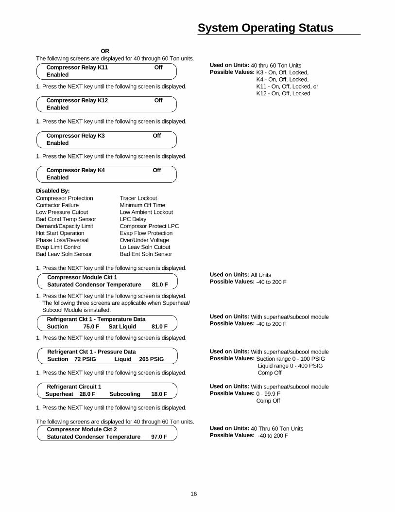
ORThe following screens are displayed for 40 through 60 Ton units.
Used on Units: 40 thru 60 Ton UnitsPossible Values: K3 - On, Off, Locked, K4 - On, Off, Locked,
1. Press the NEXT key until the following screen is displayed. K11 - On, Off, Locked, or K12 - On, Off, Locked
1. Press the NEXT key until the following screen is displayed.
1. Press the NEXT key until the following screen is displayed.
Disabled By:Compressor Protection Tracer LockoutContactor Failure Minimum Off TimeLow Pressure Cutout Low Ambient LockoutBad Cond Temp Sensor LPC DelayDemand/Capacity Limit Comprssor Protect LPCHot Start Operation Evap Flow ProtectionPhase Loss/Reversal Over/Under VoltageEvap Limit Control Lo Leav Soln CutoutBad Leav Soln Sensor Bad Ent Soln Sensor
1. Press the NEXT key until the following screen is displayed. Used on Units: All UnitsPossible Values: -40 to 200 F
1. Press the NEXT key until the following screen is displayed. The following three screens are applicable when Superheat/ Subcool Module is installed.
Used on Units: With superheat/subcool modulePossible Values: -40 to 200 F
1. Press the NEXT key until the following screen is displayed.
Used on Units: With superheat/subcool modulePossible Values: Suction range 0 - 100 PSIG Liquid range 0 - 400 PSIG
1. Press the NEXT key until the following screen is displayed. Comp Off
Used on Units: With superheat/subcool modulePossible Values: 0 - 99.9 F Comp Off
1. Press the NEXT key until the following screen is displayed.
The following screens are displayed for 40 through 60 Ton units.Used on Units: 40 Thru 60 Ton UnitsPossible Values: -40 to 200 F
Compressor Relay K11 Off Enabled
Compressor Relay K12 Off Enabled
Compressor Relay K3 Off Enabled
Compressor Relay K4 Off Enabled
Compressor Module Ckt 1 Saturated Condensor Temperature 81.0 F
Refrigerant Ckt 1 - Temperature Data Suction 75.0 F Sat Liquid 81.0 F
Refrigerant Ckt 1 - Pressure Data Suction 72 PSIG Liquid 265 PSIG
Refrigerant Circuit 1 Superheat 28.0 F Subcooling 18.0 F
Compressor Module Ckt 2 Saturated Condenser Temperature 97.0 F
17
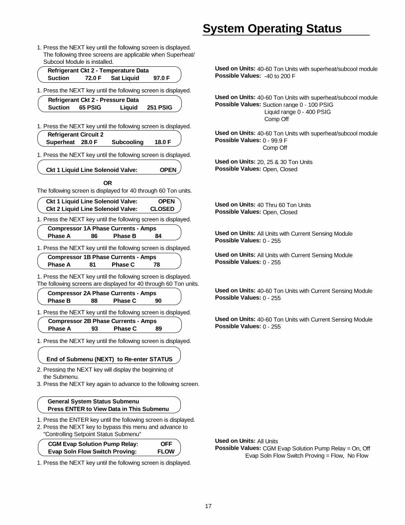
System Operating Status1. Press the NEXT key until the following screen is displayed. The following three screens are applicable when Superheat/ Subcool Module is installed.
Used on Units: 40-60 Ton Units with superheat/subcool modulePossible Values: -40 to 200 F
1. Press the NEXT key until the following screen is displayed. Used on Units: 40-60 Ton Units with superheat/subcool modulePossible Values: Suction range 0 - 100 PSIG Liquid range 0 - 400 PSIG Comp Off
1. Press the NEXT key until the following screen is displayed. Used on Units: 40-60 Ton Units with superheat/subcool modulePossible Values: 0 - 99.9 F Comp Off
1. Press the NEXT key until the following screen is displayed. Used on Units: 20, 25 & 30 Ton UnitsPossible Values: Open, Closed
ORThe following screen is displayed for 40 through 60 Ton units.
Used on Units: 40 Thru 60 Ton UnitsPossible Values: Open, Closed
1. Press the NEXT key until the following screen is displayed.
Used on Units: All Units with Current Sensing Module Possible Values: 0 - 255
1. Press the NEXT key until the following screen is displayed. Used on Units: All Units with Current Sensing Module Possible Values: 0 - 255
1. Press the NEXT key until the following screen is displayed. The following screens are displayed for 40 through 60 Ton units.
Used on Units: 40-60 Ton Units with Current Sensing Module Possible Values: 0 - 255
1. Press the NEXT key until the following screen is displayed. Used on Units: 40-60 Ton Units with Current Sensing Module Possible Values: 0 - 255
1. Press the NEXT key until the following screen is displayed.
2. Pressing the NEXT key will display the beginning of the Submenu.3. Press the NEXT key again to advance to the following screen.
1. Press the ENTER key until the following screen is displayed. 2. Press the NEXT key to bypass this menu and advance to "Controlling Setpoint Status Submenu"
Used on Units: All UnitsPossible Values: CGM Evap Solution Pump Relay = On, Off Evap Soln Flow Switch Proving = Flow, No Flow
1. Press the NEXT key until the following screen is displayed.
General System Status Submenu Press ENTER to View Data in This Submenu
CGM Evap Solution Pump Relay: OFF Evap Soln Flow Switch Proving: FLOW
Refrigerant Ckt 2 - Temperature Data Suction 72.0 F Sat Liquid 97.0 F
Refrigerant Ckt 2 - Pressure Data Suction 65 PSIG Liquid 251 PSIG
Refrigerant Circuit 2 Superheat 28.0 F Subcooling 18.0 F
Ckt 1 Liquid Line Solenoid Valve: OPEN Ckt 2 Liquid Line Solenoid Valve: CLOSED
Compressor 1A Phase Currents - Amps Phase A 86 Phase B 84
Compressor 1B Phase Currents - Amps Phase A 81 Phase C 78
Compressor 2A Phase Currents - Amps Phase B 88 Phase C 90
Compressor 2B Phase Currents - Amps Phase A 93 Phase C 89
End of Submenu (NEXT) to Re-enter STATUS
Ckt 1 Liquid Line Solenoid Valve: OPEN
18
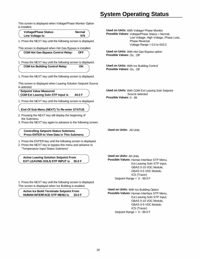
System Operating StatusThis screen is displayed when Voltage/Phase Monitor Optionis installed.
Used on Units: With Voltage/ Phase MonitorPossible Values: Voltage/Phase Status = Normal, Low Voltage, High Voltage, Phase Loss,
1. Press the NEXT key until the following screen is displayed. Phase Reversal Voltage Range = 0.0 to 633.0
This screen is displayed when Hot Gas Bypass is installed.Used on Units: With Hot Gas Bypass optionPossible Values: On, Off
1. Press the NEXT key until the following screen is displayed. Used on Units: With Ice Building ControlPossible Values: On, Off
1. Press the NEXT key until the following screen is displayed.
This screen is displayed when Leaving Solution Setpoint Sourceis selected.
Used on Units: With CGM Ext Leaving Soln Setpoint Source selectedPossible Values: 0 - 99
1. Press the NEXT key until the following screen is displayed.
2. Pressing the NEXT key will display the beginning of the Submenu.3. Press the NEXT key again to advance to the following screen.
Voltage/Phase Status: Normal Line Voltage Is: 575
CGM Hot Gas Bypass Control Relay: OFF
End Of Sub-Menu (NEXT) To Re-enter STATUS
CGM Ice Building Control Relay: ON
Setpoint Value MeasuredCGM Ext Leaving Soln STP Input is 44.0 F
Used on Units: All Units
1. Press the ENTER key until the following screen is displayed. 2. Press the NEXT key to bypass this menu and advance to "Temperature Input Status Submenu"
Used on Units: All UnitsPossible Values: Human Interface STP Menu, Ext Leaving Soln STP Input, GBAS 0-10 VDC Module, GBAS 0-5 VDC Module, ICS (Tracer) Setpoint Range = 0 - 99.9 F
1. Press the NEXT key until the following screen is displayed. This screen is displayed when Ice Building is enabled.
Used on Units: With Ice Building OptionPossible Values: Human Interface STP Menu, Ext Leaving Soln STP Input, GBAS 0-10 VDC Module, GBAS 0-5 VDC Module, ICS (Tracer) Setpoint Range = 0 - 99.9 F
Active Leaving Solution Setpoint From EXT LEAVING SOLN STP INPUT is 55.0 F
Active Ice Build Terminate Setpoint From HUMAN INTERFACE STP MENU is 33.0 F
Controlling Setpoint Status Submenu Press ENTER to View Data in This Submenu
19
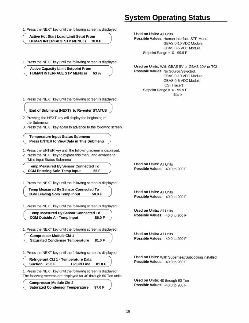
System Operating Status1. Press the NEXT key until the following screen is displayed.
Used on Units: All UnitsPossible Values: Human Interface STP Menu, GBAS 0-10 VDC Module, GBAS 0-5 VDC Module, Setpoint Range = 0 - 99.9 F
1. Press the NEXT key until the following screen is displayed. Used on Units: With GBAS 5V or GBAS 10V or TCI Possible Values: No Source Selected, GBAS 0-10 VDC Module, GBAS 0-5 VDC Module, ICS (Tracer) Setpoint Range = 0 - 99.9 F Blank
1. Press the NEXT key until the following screen is displayed.
2. Pressing the NEXT key will display the beginning of the Submenu.3. Press the NEXT key again to advance to the following screen.
1. Press the ENTER key until the following screen is displayed. 2. Press the NEXT key to bypass this menu and advance to "Misc Input Status Submenu"
Used on Units: All UnitsPossible Values: -40.0 to 200 F
1. Press the NEXT key until the following screen is displayed.
Used on Units: All UnitsPossible Values: -40.0 to 200 F
1. Press the NEXT key until the following screen is displayed. Used on Units: All UnitsPossible Values: -40.0 to 200 F
1. Press the NEXT key until the following screen is displayed. Used on Units: All UnitsPossible Values: -40.0 to 200 F
1. Press the NEXT key until the following screen is displayed. Used on Units: With Superheat/Subcooling installedPossible Values: -40.0 to 200 F
1. Press the NEXT key until the following screen is displayed. The following screens are displayed for 40 through 60 Ton units.
Used on Units: 40 through 60 TonPossible Values: -40.0 to 200 F
Active Hot Start Load Limit Setpt From HUMAN INTERFACE STP MENU is 78.0 F
Active Capacity Limit Setpoint From HUMAN INTERFACE STP MENU is 63 %
End of Submenu (NEXT) to Re-enter STATUS
Temperature Input Status Submenu Press ENTER to View Data in This Submenu
Temp Measured By Sensor Connected To CGM Entering Soln Temp Input 55 F
Temp Measured By Sensor Connected To CGM Leaving Soln Temp Input 50.0 F
Compressor Module Ckt 1 Saturated Condenser Temperature 81.0 F
Temp Measured By Sensor Connected To CGM Outside Air Temp Input 86.0 F
Compressor Module Ckt 2 Saturated Condensor Temperature 97.0 F
Refrigerant Ckt 1 - Temperature Data Suction 75.0 F Liquid Line 81.0 F
20
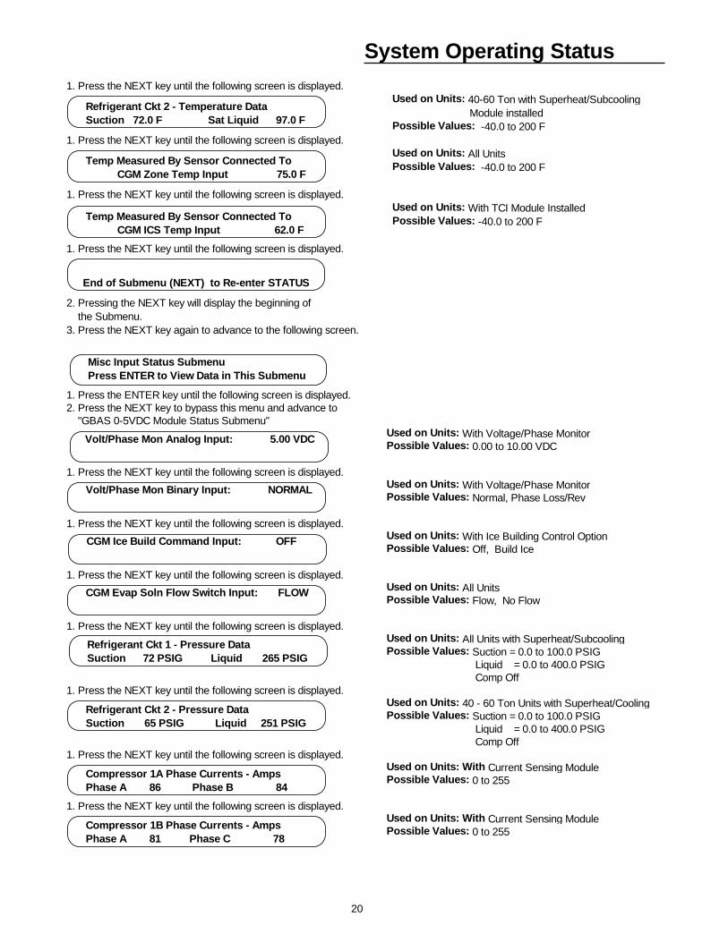
System Operating Status1. Press the NEXT key until the following screen is displayed.
Used on Units: 40-60 Ton with Superheat/Subcooling Module installedPossible Values: -40.0 to 200 F
1. Press the NEXT key until the following screen is displayed. Used on Units: All UnitsPossible Values: -40.0 to 200 F
1. Press the NEXT key until the following screen is displayed. Used on Units: With TCI Module InstalledPossible Values: -40.0 to 200 F
1. Press the NEXT key until the following screen is displayed.
2. Pressing the NEXT key will display the beginning of the Submenu.3. Press the NEXT key again to advance to the following screen.
Refrigerant Ckt 2 - Temperature Data Suction 72.0 F Sat Liquid 97.0 F
Temp Measured By Sensor Connected To CGM Zone Temp Input 75.0 F
Temp Measured By Sensor Connected To CGM ICS Temp Input 62.0 F
End of Submenu (NEXT) to Re-enter STATUS
1. Press the ENTER key until the following screen is displayed. 2. Press the NEXT key to bypass this menu and advance to "GBAS 0-5VDC Module Status Submenu"
Used on Units: With Voltage/Phase MonitorPossible Values: 0.00 to 10.00 VDC
1. Press the NEXT key until the following screen is displayed. Used on Units: With Voltage/Phase MonitorPossible Values: Normal, Phase Loss/Rev
1. Press the NEXT key until the following screen is displayed. Used on Units: With Ice Building Control OptionPossible Values: Off, Build Ice
1. Press the NEXT key until the following screen is displayed. Used on Units: All UnitsPossible Values: Flow, No Flow
1. Press the NEXT key until the following screen is displayed. Used on Units: All Units with Superheat/SubcoolingPossible Values: Suction = 0.0 to 100.0 PSIG Liquid = 0.0 to 400.0 PSIG Comp Off
1. Press the NEXT key until the following screen is displayed. Used on Units: 40 - 60 Ton Units with Superheat/CoolingPossible Values: Suction = 0.0 to 100.0 PSIG Liquid = 0.0 to 400.0 PSIG Comp Off
1. Press the NEXT key until the following screen is displayed. Used on Units: With Current Sensing ModulePossible Values: 0 to 255
1. Press the NEXT key until the following screen is displayed. Used on Units: With Current Sensing ModulePossible Values: 0 to 255
Misc Input Status Submenu Press ENTER to View Data in This Submenu
CGM Ice Build Command Input: OFF
CGM Evap Soln Flow Switch Input: FLOW
Refrigerant Ckt 1 - Pressure Data Suction 72 PSIG Liquid 265 PSIG
Refrigerant Ckt 2 - Pressure Data Suction 65 PSIG Liquid 251 PSIG
Compressor 1A Phase Currents - Amps Phase A 86 Phase B 84
Compressor 1B Phase Currents - Amps Phase A 81 Phase C 78
Volt/Phase Mon Analog Input: 5.00 VDC
Volt/Phase Mon Binary Input: NORMAL
21
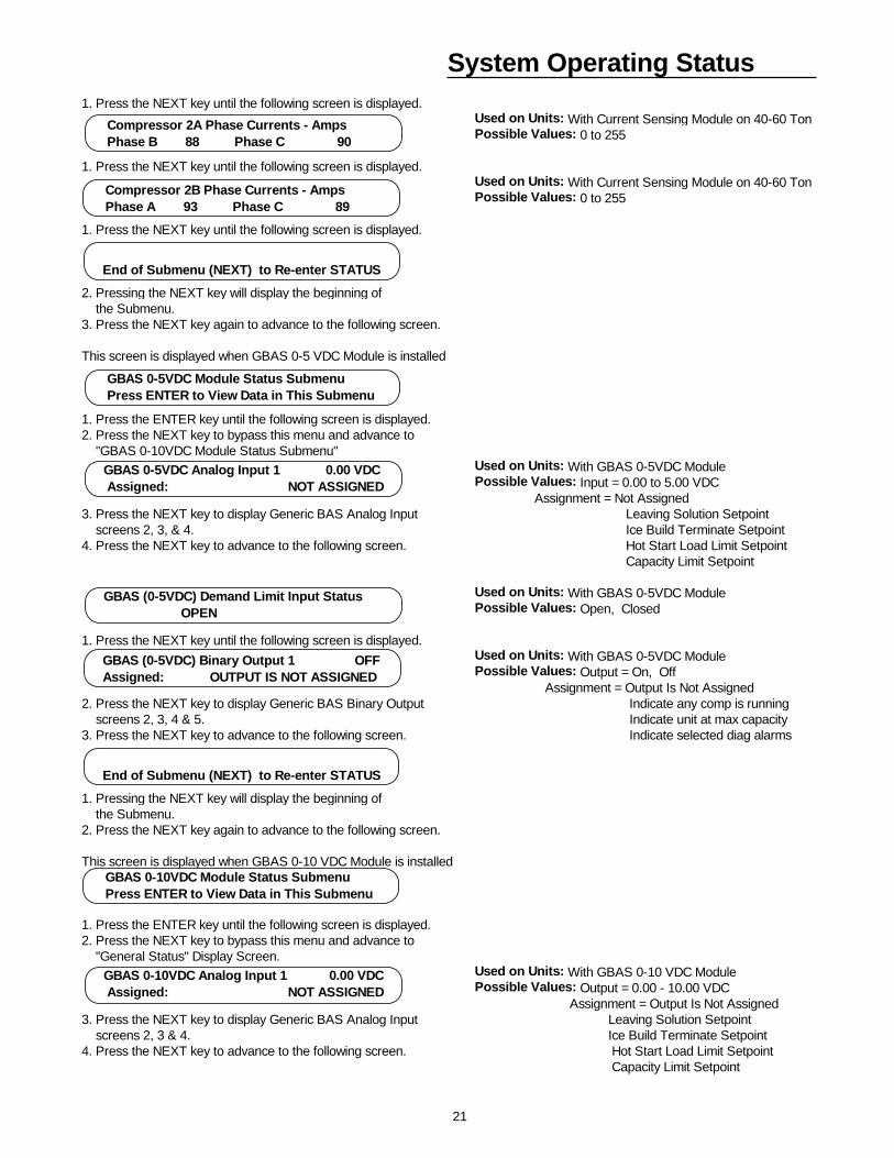
System Operating Status1. Press the NEXT key until the following screen is displayed.
Used on Units: With Current Sensing Module on 40-60 TonPossible Values: 0 to 255
1. Press the NEXT key until the following screen is displayed. Used on Units: With Current Sensing Module on 40-60 TonPossible Values: 0 to 255
1. Press the NEXT key until the following screen is displayed.
2. Pressing the NEXT key will display the beginning of the Submenu.3. Press the NEXT key again to advance to the following screen.
This screen is displayed when GBAS 0-5 VDC Module is installed
1. Press the ENTER key until the following screen is displayed. 2. Press the NEXT key to bypass this menu and advance to "GBAS 0-10VDC Module Status Submenu"
Used on Units: With GBAS 0-5VDC ModulePossible Values: Input = 0.00 to 5.00 VDC Assignment = Not Assigned
3. Press the NEXT key to display Generic BAS Analog Input Leaving Solution Setpoint screens 2, 3, & 4. Ice Build Terminate Setpoint4. Press the NEXT key to advance to the following screen. Hot Start Load Limit Setpoint
Capacity Limit Setpoint
Used on Units: With GBAS 0-5VDC ModulePossible Values: Open, Closed
1. Press the NEXT key until the following screen is displayed. Used on Units: With GBAS 0-5VDC ModulePossible Values: Output = On, Off Assignment = Output Is Not Assigned
2. Press the NEXT key to display Generic BAS Binary Output Indicate any comp is running screens 2, 3, 4 & 5. Indicate unit at max capacity3. Press the NEXT key to advance to the following screen. Indicate selected diag alarms
1. Pressing the NEXT key will display the beginning of the Submenu.2. Press the NEXT key again to advance to the following screen.
This screen is displayed when GBAS 0-10 VDC Module is installed
1. Press the ENTER key until the following screen is displayed. 2. Press the NEXT key to bypass this menu and advance to "General Status" Display Screen.
Used on Units: With GBAS 0-10 VDC ModulePossible Values: Output = 0.00 - 10.00 VDC Assignment = Output Is Not Assigned
3. Press the NEXT key to display Generic BAS Analog Input Leaving Solution Setpoint screens 2, 3 & 4. Ice Build Terminate Setpoint4. Press the NEXT key to advance to the following screen. Hot Start Load Limit Setpoint
Capacity Limit Setpoint
Compressor 2A Phase Currents - Amps Phase B 88 Phase C 90
Compressor 2B Phase Currents - Amps Phase A 93 Phase C 89
End of Submenu (NEXT) to Re-enter STATUS
GBAS 0-5VDC Module Status Submenu Press ENTER to View Data in This Submenu
GBAS 0-5VDC Analog Input 1 0.00 VDC Assigned: NOT ASSIGNED
GBAS (0-5VDC) Demand Limit Input Status OPEN
GBAS (0-5VDC) Binary Output 1 OFF Assigned: OUTPUT IS NOT ASSIGNED
End of Submenu (NEXT) to Re-enter STATUS
GBAS 0-10VDC Module Status Submenu Press ENTER to View Data in This Submenu
GBAS 0-10VDC Analog Input 1 0.00 VDC Assigned: NOT ASSIGNED
22
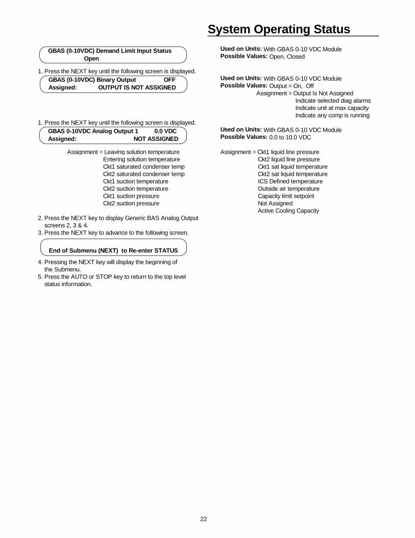
System Operating StatusUsed on Units: With GBAS 0-10 VDC ModulePossible Values: Open, Closed
1. Press the NEXT key until the following screen is displayed. Used on Units: With GBAS 0-10 VDC ModulePossible Values: Output = On, Off Assignment = Output Is Not Assigned Indicate selected diag alarms Indicate unit at max capacity Indicate any comp is running
1. Press the NEXT key until the following screen is displayed. Used on Units: With GBAS 0-10 VDC ModulePossible Values: 0.0 to 10.0 VDC
Assignment = Leaving solution temperature Assignment = Ckt1 liquid line pressure Entering solution temperature Ckt2 liquid line pressure Ckt1 saturated condenser temp Ckt1 sat liquid temperature Ckt2 saturated condenser temp Ckt2 sat liquid temperature Ckt1 suction temperature ICS Defined temperature Ckt2 suction temperature Outside air temperature Ckt1 suction pressure Capacity limit setpoint Ckt2 suction pressure Not Assigned
Active Cooling Capacity2. Press the NEXT key to display Generic BAS Analog Output screens 2, 3 & 4. 3. Press the NEXT key to advance to the following screen.
4. Pressing the NEXT key will display the beginning of the Submenu.5. Press the AUTO or STOP key to return to the top level status information.
GBAS (0-10VDC) Demand Limit Input Status Open
GBAS (0-10VDC) Binary Output OFF Assigned: OUTPUT IS NOT ASSIGNED
End of Submenu (NEXT) to Re-enter STATUS
GBAS 0-10VDC Analog Output 1 0.0 VDC Assigned: NOT ASSIGNED
23
System ProgrammingAfter the unit is installed, the CGM must be programmedwith certain setup information (chilled solution setpoints, ONand OFF times, system defaults, setpoint sources, etc...) inorder to operate and function properly. The data necessaryfor unit operation will vary depending on certain factorssuch as unit size, type, and installed options.
This section of the manual provides step by step instruc-tions for programming this information. Also provided are in-structions for checking unit operating status, accessing andclearing diagnostics, and performing service tests.
Some of the displays shown in this manual may not appearon the Human Interface (HI) LCD screen during program-ing. Only the applicable screens for the specific unit optionsand operating parameters will be displayed.
Start with the first setup screen in the SETUP menu andprogram the necessary information by completing the stepslocated below each illustrated window. Information that per-tains to when the screens are applicable, the factory presetvalues, and the possible values that may be designated islocated to the right of each programmable screen.
Ignore the steps that do not apply to your unit and applica-tion, and move on to the next applicable set of instructionsin the manual. Continue this process until all applicablescreens are programmed with the required information.
SETUP Menu
The setup menu is used to input initial operating information such as control parameters, functions enable/disable, text dis-play (language), temperature display (C or F), and system tuning parameters. When a setup screen is displayed for 30 min-utes without a key being pressed, the LCD screen will revert to the appropriate power-up display. If this happens, press theSETUP key again to return to the setup menu.
Information Format
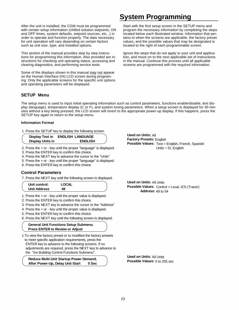
1. Press the SETUP key to display the following screen.Used on Units: AllFactory Presets: EnglishPossible Values: Text = English, French, Spanish
2. Press the + or - key until the proper "language" is displayed. Units = SI, English3. Press the ENTER key to confirm this choice.4. Press the NEXT key to advance the cursor to the "Units"5. Press the + or - key until the proper "language" is displayed.6. Press the ENTER key to confirm this choice.
Display Text in ENGLISH LANGUAGE Display Units in ENGLISH
Control Parameters7. Press the NEXT key until the following screen is displayed.
Used on Units: All UnitsPossible Values: Control = Local, ICS (Tracer) Address: 49 to 54
1. Press the + or - key until the proper value is displayed.2. Press the ENTER key to confirm this choice.3. Press the NEXT key to advance the cursor to the "Address"4. Press the + or - key until the proper value is displayed.5. Press the ENTER key to confirm this choice.6. Press the NEXT key until the following screen is displayed.
1.To view the factory preset or to modified the factory presets to meet specific application requirements, press the ENTER key to advance to the following screens. If no adjustments are required, press the NEXT key to advance to the "Ice Building Control Functions Submenu".
Used on Units: All UnitsPossible Values: 0 to 255 sec
Unit control: LOCAL Unit Address 49
General Unit Functions Setup Submenu Press ENTER to Review or Adjust
Reduce Multi-Unit Startup Power Demand. After Power-Up, Delay Unit Start 0 Sec
24
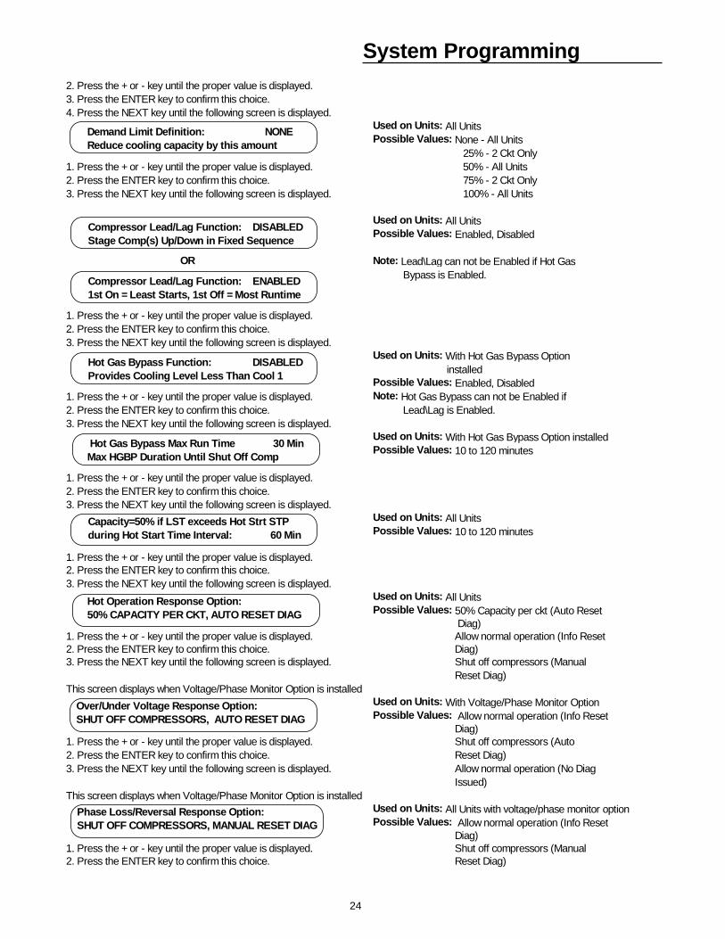
System Programming2. Press the + or - key until the proper value is displayed.3. Press the ENTER key to confirm this choice.4. Press the NEXT key until the following screen is displayed.
Used on Units: All UnitsPossible Values: None - All Units 25% - 2 Ckt Only
1. Press the + or - key until the proper value is displayed. 50% - All Units 2. Press the ENTER key to confirm this choice. 75% - 2 Ckt Only 3. Press the NEXT key until the following screen is displayed. 100% - All Units
Used on Units: All UnitsPossible Values: Enabled, Disabled
OR Note: Lead\Lag can not be Enabled if Hot Gas Bypass is Enabled.
1. Press the + or - key until the proper value is displayed.2. Press the ENTER key to confirm this choice.3. Press the NEXT key until the following screen is displayed.
Used on Units: With Hot Gas Bypass Option installedPossible Values: Enabled, Disabled
1. Press the + or - key until the proper value is displayed. Note: Hot Gas Bypass can not be Enabled if2. Press the ENTER key to confirm this choice. Lead\Lag is Enabled.3. Press the NEXT key until the following screen is displayed.
Used on Units: With Hot Gas Bypass Option installedPossible Values: 10 to 120 minutes
1. Press the + or - key until the proper value is displayed.2. Press the ENTER key to confirm this choice.3. Press the NEXT key until the following screen is displayed.
Used on Units: All UnitsPossible Values: 10 to 120 minutes
1. Press the + or - key until the proper value is displayed.2. Press the ENTER key to confirm this choice.3. Press the NEXT key until the following screen is displayed.
Used on Units: All UnitsPossible Values: 50% Capacity per ckt (Auto Reset Diag)
1. Press the + or - key until the proper value is displayed. Allow normal operation (Info Reset2. Press the ENTER key to confirm this choice. Diag)3. Press the NEXT key until the following screen is displayed. Shut off compressors (Manual
Reset Diag)This screen displays when Voltage/Phase Monitor Option is installed
Used on Units: With Voltage/Phase Monitor OptionPossible Values: Allow normal operation (Info Reset Diag)
1. Press the + or - key until the proper value is displayed. Shut off compressors (Auto2. Press the ENTER key to confirm this choice. Reset Diag)3. Press the NEXT key until the following screen is displayed. Allow normal operation (No Diag
Issued)This screen displays when Voltage/Phase Monitor Option is installed
Used on Units: All Units with voltage/phase monitor optionPossible Values: Allow normal operation (Info Reset Diag)
1. Press the + or - key until the proper value is displayed. Shut off compressors (Manual 2. Press the ENTER key to confirm this choice. Reset Diag)
Demand Limit Definition: NONE Reduce cooling capacity by this amount
Compressor Lead/Lag Function: DISABLED Stage Comp(s) Up/Down in Fixed Sequence
Capacity=50% if LST exceeds Hot Strt STP during Hot Start Time Interval: 60 Min
Hot Operation Response Option: 50% CAPACITY PER CKT, AUTO RESET DIAG
Over/Under Voltage Response Option:SHUT OFF COMPRESSORS, AUTO RESET DIAG
Phase Loss/Reversal Response Option:SHUT OFF COMPRESSORS, MANUAL RESET DIAG
Hot Gas Bypass Function: DISABLED Provides Cooling Level Less Than Cool 1
Hot Gas Bypass Max Run Time 30 Min Max HGBP Duration Until Shut Off Comp
Compressor Lead/Lag Function: ENABLED 1st On = Least Starts, 1st Off = Most Runtime
25
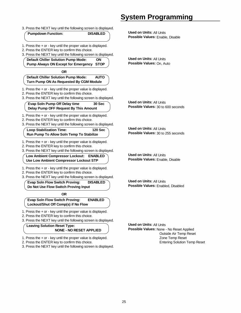
System Programming3. Press the NEXT key until the following screen is displayed.
Used on Units: All UnitsPossible Values: Enable, Disable
1. Press the + or - key until the proper value is displayed.2. Press the ENTER key to confirm this choice.3. Press the NEXT key until the following screen is displayed.
Used on Units: All UnitsPossible Values: On, Auto
OR
1. Press the + or - key until the proper value is displayed.2. Press the ENTER key to confirm this choice.3. Press the NEXT key until the following screen is displayed.
Used on Units: All UnitsPossible Values: 30 to 600 seconds
1. Press the + or - key until the proper value is displayed.2. Press the ENTER key to confirm this choice.3. Press the NEXT key until the following screen is displayed.
Used on Units: All UnitsPossible Values: 30 to 255 seconds
1. Press the + or - key until the proper value is displayed.2. Press the ENTER key to confirm this choice.3. Press the NEXT key until the following screen is displayed.
Used on Units: All UnitsPossible Values: Enable, Disable
1. Press the + or - key until the proper value is displayed.2. Press the ENTER key to confirm this choice.3. Press the NEXT key until the following screen is displayed.
Used on Units: All UnitsPossible Values: Enabled, Disabled
OR
1. Press the + or - key until the proper value is displayed.2. Press the ENTER key to confirm this choice.3. Press the NEXT key until the following screen is displayed.
Used on Units: All UnitsPossible Values: None - No Reset Applied Outside Air Temp Reset
1. Press the + or - key until the proper value is displayed. Zone Temp Reset2. Press the ENTER key to confirm this choice. Entering Solution Temp Reset3. Press the NEXT key until the following screen is displayed.
Pumpdown Function: DISABLED
Default Chiller Solution Pump Mode: ON Pump Always ON Except for Emergency STOP
Evap Soln Pump Off Delay time 30 Sec Delay Pump OFF Request By This Amount
Loop Stabilization Time: 120 Sec Run Pump To Allow Soln Temp To Stabilize
Low Ambient Compressor Lockout: ENABLED Use Low Ambient Compressor Lockout STP
Evap Soln Flow Switch Proving: DISABLED Do Not Use Flow Switch Proving Input
Leaving Solution Reset Type: NONE - NO RESET APPLIED
Default Chiller Solution Pump Mode: AUTO Turn Pump ON As Requested By CGM Module
Evap Soln Flow Switch Proving: ENABLED Lockout/Shut Off Comp(s) if No Flow
26
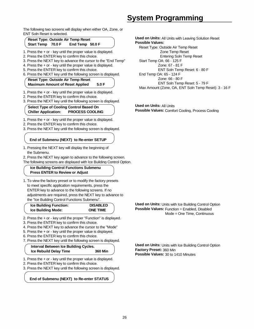
System ProgrammingThe following two screens will display when either OA, Zone, orENT Soln Reset is selected.
Used on Units: All Units with Leaving Solution ResetPossible Values: Reset Type: Outside Air Temp Reset
1. Press the + or - key until the proper value is displayed. Zone Temp Reset2. Press the ENTER key to confirm this choice. Entering Soln Temp Reset3. Press the NEXT key to advance the cursor to the "End Temp" Start Temp OA: 66 - 125 F4. Press the + or - key until the proper value is displayed. Zone: 67 - 81 F5. Press the ENTER key to confirm this choice. ENT Soln Temp Reset: 6 - 80 F6. Press the NEXT key until the following screen is displayed. End Temp OA: 65 - 124 F
Zone: 66 - 80 F ENT Soln Temp Reset: 5 - 79 F Max Amount (Zone, OA, ENT Soln Temp Reset): 3 - 16 F
1. Press the + or - key until the proper value is displayed.2. Press the ENTER key to confirm this choice.3. Press the NEXT key until the following screen is displayed.
Used on Units: All UnitsPossible Values: Comfort Cooling, Process Cooling
1. Press the + or - key until the proper value is displayed.2. Press the ENTER key to confirm this choice.3. Press the NEXT key until the following screen is displayed.
1. Pressing the NEXT key will display the beginning of the Submenu.2. Press the NEXT key again to advance to the following screen.The following screens are displayed with Ice Building Control Option.
1. To view the factory preset or to modify the factory presets to meet specific application requirements, press the ENTER key to advance to the following screens. If no adjustments are required, press the NEXT key to advance to the "Ice Building Control Functions Submenu".
Used on Units: Units with Ice Building Control OptionPossible Values: Function = Enabled, Disabled Mode = One Time, Continuous
2. Press the + or - key until the proper "Function" is displayed.3. Press the ENTER key to confirm this choice.4. Press the NEXT key to advance the cursor to the "Mode"5. Press the + or - key until the proper value is displayed.6. Press the ENTER key to confirm this choice.7. Press the NEXT key until the following screen is displayed.
Used on Units: Units with Ice Building Control OptionFactory Preset: 360 MinPossible Values: 30 to 1410 Minutes
1. Press the + or - key until the proper value is displayed.2. Press the ENTER key to confirm this choice.3. Press the NEXT key until the following screen is displayed.
Ice Building Control Functions Submenu Press ENTER to Review or Adjust
Ice Building Function: DISABLED Ice Building Mode: ONE TIME
Interval Between Ice Building Cycles. Ice Rebuild Delay Time 360 Min
End of Submenu (NEXT) to Re-enter STATUS
Select Type of Cooling Control Based On Chiller Application: PROCESS COOLING
End of Submenu (NEXT) to Re-enter SETUP
Reset Type: Outside Air Temp Reset Start Temp 70.0 F End Temp 50.0 F
Reset Type: Outside Air Temp Reset Maximum Amount of Reset Applied 5.0 F
27
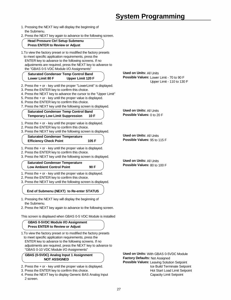
System Programming1. Pressing the NEXT key will display the beginning of the Submenu.2. Press the NEXT key again to advance to the following screen.
1.To view the factory preset or to modified the factory presets to meet specific application requirements, press the ENTER key to advance to the following screens. If no adjustments are required, press the NEXT key to advance to the "GBAS 0-5 VDC Module I/O Assignments"
Used on Units: All UnitsPossible Values: Lower Limit - 70 to 90 F Upper Limit - 110 to 130 F
2. Press the + or - key until the proper "LowerLimit" is displayed.3. Press the ENTER key to confirm this choice.4. Press the NEXT key to advance the cursor to the "Upper Limit"5. Press the + or - key until the proper value is displayed.6. Press the ENTER key to confirm this choice.7. Press the NEXT key until the following screen is displayed.
Used on Units: All UnitsPossible Values: 0 to 20 F
1. Press the + or - key until the proper value is displayed.2. Press the ENTER key to confirm this choice.3. Press the NEXT key until the following screen is displayed.
Used on Units: All UnitsPossible Values: 95 to 115 F
1. Press the + or - key until the proper value is displayed.2. Press the ENTER key to confirm this choice.3. Press the NEXT key until the following screen is displayed.
Used on Units: All UnitsPossible Values: 80 to 100 F
1. Press the + or - key until the proper value is displayed.2. Press the ENTER key to confirm this choice.3. Press the NEXT key until the following screen is displayed.
1. Pressing the NEXT key will display the beginning of the Submenu.2. Press the NEXT key again to advance to the following screen.
This screen is displayed when GBAS 0-5 VDC Module is installed
1.To view the factory preset or to modified the factory presets to meet specific application requirements, press the ENTER key to advance to the following screens. If no adjustments are required, press the NEXT key to advance to "GBAS 0-10 VDC Module I/O Assignments"
Used on Units: With GBAS 0-5VDC ModuleFactory Defaults: Not AssignedPossible Values: Leaving Solution Setpoint
2. Press the + or - key until the proper value is displayed. Ice Build Terminate Setpoint3. Press the ENTER key to confirm this choice. Hot Start Load Limit Setpoint4. Press the NEXT key to display Generic BAS Analog Input Capacity Limit Setpoint 2 screen.
Head Pressure Ctrl Setup Submenu Press ENTER to Review or Adjust
Saturated Condenser Temp Control Band Lower Limit 80 F Upper Limit 120 F
Saturated Condenser Temp Control Band Temporary Low Limit Suppression 10 F
Saturated Condenser Temperature Efficiency Check Point 105 F
Saturated Condenser Temperature Low Ambient Control Point 90 F
End of Submenu (NEXT) to Re-enter STATUS
GBAS 0-5VDC Module I/O Assignment Press ENTER to Review or Adjust
GBAS (0-5VDC) Analog Input 1 Assignment NOT ASSIGNED
28
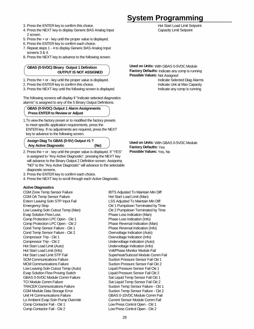
System Programming3. Press the ENTER key to confirm this choice. Hot Start Load Limit Setpoint4. Press the NEXT key to display Generic BAS Analog Input Capacity Limit Setpoint 2 screen. 5. Press the + or - key until the proper value is displayed.6. Press the ENTER key to confirm each choice.7. Repeat steps 1 - 4 to display Generic BAS Analog Input screens 3 & 4. 8. Press the NEXT key to advance to the following screen.
Used on Units: With GBAS 0-5VDC ModuleFactory Defaults: Indicate any comp is runningPossible Values: Not Assigned
1. Press the + or - key until the proper value is displayed. Indicate Selected Diag Alarms2. Press the ENTER key to confirm this choice. Indicate Unit at Max Capacity3. Press the NEXT key until the following screen is displayed. Indicate any comp is running
The following screens will display if "Indicate selected diagnosticsalarms" is assigned to any of the 5 Binary Output Definitions.
1.To view the factory preset or to modified the factory presets to meet specific application requirements, press the ENTER key. If no adjustments are required, press the NEXT key to advance to the following screen.
Used on Units: With GBAS 0-5VDC ModuleFactory Defaults: Yes
2. Press the + or - key until the proper value is displayed. If "YES" Possible Values: Yes, No is assigned to "Any Active Diagnostic", pressing the NEXT key will advance to the Binary Output 2 Definition screen. Assigning "NO" to the "Any Active Diagnostic" will advance to the selectable diagnostic screens.3. Press the ENTER key to confirm each choice.4. Press the NEXT key to scroll through each Active Diagnostic.
Active DiagnosticsCGM Zone Temp Sensor Failure IBTS Adjusted To Maintain Min DiffCGM OA Temp Sensor Failure Hot Start Load Limit (Man)Extern Leaving Soln STP Input Fail LSS Adjusted To Maintain Min DiffEmergency Stop Ckt 1 Pumpdown Terminated by TimeLow Leaving Soln Cutout Temp (Man) Ckt 2 Pumpdown Terminated by TimeEvap Solution Flow Loss Phase Loss Indication (Man)Comp Protection LPC Open - Ckt 1 Phase Loss Indication (Info)Comp Protection LPC Open - Ckt 2 Phase Reversal Indication (Man)Cond Temp Sensor Failure - Ckt 1 Phase Reversal Indication (Info)Cond Temp Sensor Failure - Ckt 2 Overvoltage Indication (Auto)Compressor Trip - Ckt 1 Overvoltage Indication (Info)Compressor Trip - Ckt 2 Undervoltage Indication (Auto)Hot Start Load Limit (Auto) Undervoltage Indication (Info)Hot Start Load Limit (Info) Volt/Phase Monitor Module FailHot Start Load Limit STP Fail Superheat/Subcool Module Comm FailSCM Communications Failure Suction Pressure Sensor Fail Ckt 1MCM Communications Failure Suction Pressure Sensor Fail Ckt 2Low Leaving Soln Cutout Temp (Auto) Liquid Pressure Sensor Fail Ckt 1Evap Solution Flow Proving Switch Liquid Pressure Sensor Fail Ckt 2GBAS 0-5VDC Module Comm Failure Sat Liquid Temp Sensor Fail Ckt 1TCI Module Comm Failure Sat Liquid Temp Sensor Fail Ckt 2TRACER Communications Failure Suction Temp Sensor Failure - Ckt 1CGM Module Data Storage Error Suction Temp Sensor Failure - Ckt 2Unit HI Communications Failure GBAS 0-10VDC Module Comm FailLo Ambient Evap Soln Pump Override Current Sensor Module Comm FailComp Contactor Fail - Ckt 1 Low Press Control Open - Ckt 1Comp Contactor Fail - Ckt 2 Low Press Control Open - Ckt 2
GBAS (0-5VDC) Binary Output 1 Definition OUTPUT IS NOT ASSIGNED
GBAS (0-5VDC) Output 1 Alarm Assignments Press ENTER to Review or Adjust
Assign Diag To GBAS (0-5V) Output #1 ? Any Active Diagnostic (No)
29
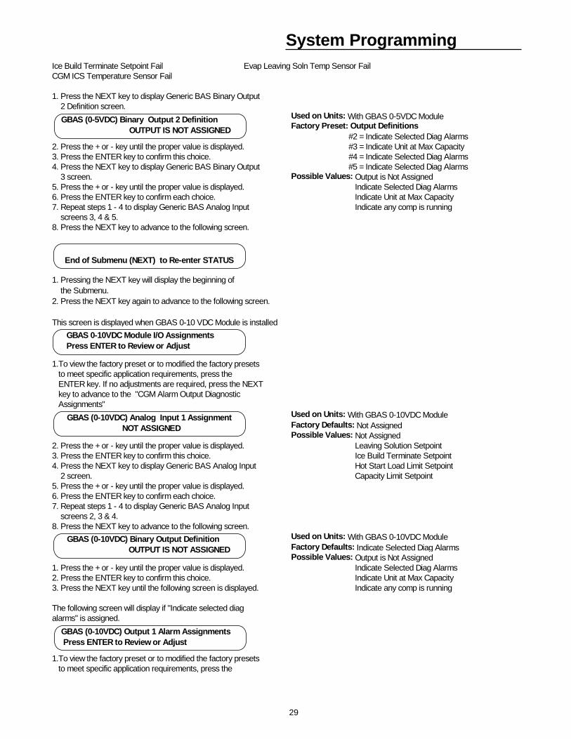
System ProgrammingIce Build Terminate Setpoint Fail Evap Leaving Soln Temp Sensor FailCGM ICS Temperature Sensor Fail
1. Press the NEXT key to display Generic BAS Binary Output 2 Definition screen.
Used on Units: With GBAS 0-5VDC ModuleFactory Preset: Output Definitions #2 = Indicate Selected Diag Alarms
2. Press the + or - key until the proper value is displayed. #3 = Indicate Unit at Max Capacity3. Press the ENTER key to confirm this choice. #4 = Indicate Selected Diag Alarms4. Press the NEXT key to display Generic BAS Binary Output #5 = Indicate Selected Diag Alarms 3 screen. Possible Values: Output is Not Assigned5. Press the + or - key until the proper value is displayed. Indicate Selected Diag Alarms6. Press the ENTER key to confirm each choice. Indicate Unit at Max Capacity7. Repeat steps 1 - 4 to display Generic BAS Analog Input Indicate any comp is running screens 3, 4 & 5. 8. Press the NEXT key to advance to the following screen.
1. Pressing the NEXT key will display the beginning of the Submenu.2. Press the NEXT key again to advance to the following screen.
This screen is displayed when GBAS 0-10 VDC Module is installed
1.To view the factory preset or to modified the factory presets to meet specific application requirements, press the ENTER key. If no adjustments are required, press the NEXT key to advance to the "CGM Alarm Output Diagnostic Assignments"
Used on Units: With GBAS 0-10VDC ModuleFactory Defaults: Not AssignedPossible Values: Not Assigned
2. Press the + or - key until the proper value is displayed. Leaving Solution Setpoint3. Press the ENTER key to confirm this choice. Ice Build Terminate Setpoint4. Press the NEXT key to display Generic BAS Analog Input Hot Start Load Limit Setpoint 2 screen. Capacity Limit Setpoint5. Press the + or - key until the proper value is displayed.6. Press the ENTER key to confirm each choice.7. Repeat steps 1 - 4 to display Generic BAS Analog Input screens 2, 3 & 4. 8. Press the NEXT key to advance to the following screen.
Used on Units: With GBAS 0-10VDC ModuleFactory Defaults: Indicate Selected Diag AlarmsPossible Values: Output is Not Assigned
1. Press the + or - key until the proper value is displayed. Indicate Selected Diag Alarms2. Press the ENTER key to confirm this choice. Indicate Unit at Max Capacity3. Press the NEXT key until the following screen is displayed. Indicate any comp is running
The following screen will display if "Indicate selected diagalarms" is assigned.
1.To view the factory preset or to modified the factory presets to meet specific application requirements, press the
End of Submenu (NEXT) to Re-enter STATUS
GBAS 0-10VDC Module I/O Assignments Press ENTER to Review or Adjust
GBAS (0-10VDC) Analog Input 1 Assignment NOT ASSIGNED
GBAS (0-10VDC) Binary Output Definition OUTPUT IS NOT ASSIGNED
GBAS (0-5VDC) Binary Output 2 Definition OUTPUT IS NOT ASSIGNED
GBAS (0-10VDC) Output 1 Alarm Assignments Press ENTER to Review or Adjust
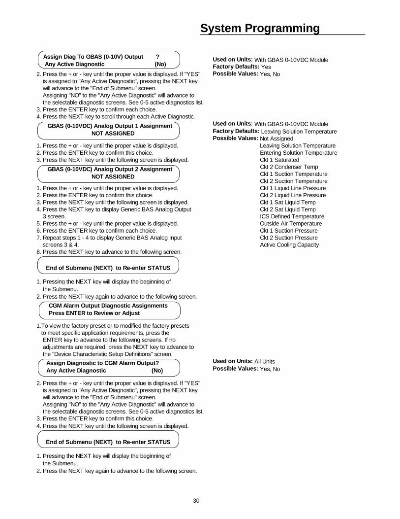
30
System Programming
Used on Units: With GBAS 0-10VDC ModuleFactory Defaults: Yes
2. Press the + or - key until the proper value is displayed. If "YES" Possible Values: Yes, No is assigned to "Any Active Diagnostic", pressing the NEXT key will advance to the "End of Submenu" screen. Assigning "NO" to the "Any Active Diagnostic" will advance to the selectable diagnostic screens. See 0-5 active diagnostics list.3. Press the ENTER key to confirm each choice.4. Press the NEXT key to scroll through each Active Diagnostic.
Used on Units: With GBAS 0-10VDC ModuleFactory Defaults: Leaving Solution TemperaturePossible Values: Not Assigned
1. Press the + or - key until the proper value is displayed. Leaving Solution Temperature2. Press the ENTER key to confirm this choice. Entering Solution Temperature3. Press the NEXT key until the following screen is displayed. Ckt 1 Saturated
Ckt 2 Condenser Temp Ckt 1 Suction Temperature Ckt 2 Suction Temperature
1. Press the + or - key until the proper value is displayed. Ckt 1 Liquid Line Pressure2. Press the ENTER key to confirm this choice. Ckt 2 Liquid Line Pressure3. Press the NEXT key until the following screen is displayed. Ckt 1 Sat Liquid Temp4. Press the NEXT key to display Generic BAS Analog Output Ckt 2 Sat Liquid Temp 3 screen. ICS Defined Temperature5. Press the + or - key until the proper value is displayed. Outside Air Temperature6. Press the ENTER key to confirm each choice. Ckt 1 Suction Pressure7. Repeat steps 1 - 4 to display Generic BAS Analog Input Ckt 2 Suction Pressure screens 3 & 4. Active Cooling Capacity8. Press the NEXT key to advance to the following screen.
1. Pressing the NEXT key will display the beginning of the Submenu.2. Press the NEXT key again to advance to the following screen.
1.To view the factory preset or to modified the factory presets to meet specific application requirements, press the ENTER key to advance to the following screens. If no adjustments are required, press the NEXT key to advance to the "Device Characteristic Setup Definitions" screen.
Used on Units: All UnitsPossible Values: Yes, No
2. Press the + or - key until the proper value is displayed. If "YES" is assigned to "Any Active Diagnostic", pressing the NEXT key will advance to the "End of Submenu" screen. Assigning "NO" to the "Any Active Diagnostic" will advance to the selectable diagnostic screens. See 0-5 active diagnostics list.3. Press the ENTER key to confirm this choice.4. Press the NEXT key until the following screen is displayed.
1. Pressing the NEXT key will display the beginning of the Submenu.2. Press the NEXT key again to advance to the following screen.
End of Submenu (NEXT) to Re-enter STATUS
CGM Alarm Output Diagnostic Assignments Press ENTER to Review or Adjust
Assign Diagnostic to CGM Alarm Output? Any Active Diagnostic (No)
End of Submenu (NEXT) to Re-enter STATUS
GBAS (0-10VDC) Analog Output 1 Assignment NOT ASSIGNED
Assign Diag To GBAS (0-10V) Output ? Any Active Diagnostic (No)
GBAS (0-10VDC) Analog Output 2 Assignment NOT ASSIGNED
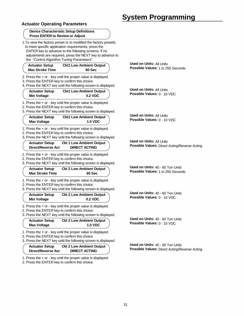
31
System ProgrammingActuator Operating Parameters
1.To view the factory preset or to modified the factory presets to meet specific application requirements, press the ENTER key to advance to the following screens. If no adjustments are required, press the NEXT key to advance to the "Control Algorithm Tuning Parameters".
Used on Units: All UnitsPossible Values: 1 to 255 Seconds
2. Press the + or - key until the proper value is displayed.3. Press the ENTER key to confirm this choice.4. Press the NEXT key until the following screen is displayed.
Used on Units: All UnitsPossible Values: 0 - 10 VDC
1. Press the + or - key until the proper value is displayed.2. Press the ENTER key to confirm this choice.3. Press the NEXT key until the following screen is displayed.
Used on Units: All UnitsPossible Values: 0 - 10 VDC
1. Press the + or - key until the proper value is displayed.2. Press the ENTER key to confirm this choice.3. Press the NEXT key until the following screen is displayed.
Used on Units: All UnitsPossible Values: Direct Acting/Reverse Acting
1. Press the + or - key until the proper value is displayed.2. Press the ENTER key to confirm this choice.3. Press the NEXT key until the following screen is displayed.
Used on Units: 40 - 60 Ton UnitsPossible Values: 1 to 255 Seconds
1. Press the + or - key until the proper value is displayed.2. Press the ENTER key to confirm this choice.3. Press the NEXT key until the following screen is displayed.
Used on Units: 40 - 60 Ton UnitsPossible Values: 0 - 10 VDC
1. Press the + or - key until the proper value is displayed.2. Press the ENTER key to confirm this choice.3. Press the NEXT key until the following screen is displayed.
Used on Units: 40 - 60 Ton UnitsPossible Values: 0 - 10 VDC
1. Press the + or - key until the proper value is displayed.2. Press the ENTER key to confirm this choice.3. Press the NEXT key until the following screen is displayed.
Used on Units: 40 - 60 Ton UnitsPossible Values: Direct Acting/Reverse Acting
1. Press the + or - key until the proper value is displayed.2. Press the ENTER key to confirm this choice.
Device Characteristic Setup Definitions Press ENTER to Review or Adjust
Actuator Setup Ckt1 Low Ambient Output Max Stroke Time 60 Sec
Actuator Setup Ckt1 Low Ambient Output Min Voltage 0.2 VDC
Actuator Setup Ckt1 Low Ambient Output Max Voltage 1.0 VDC
Actuator Setup Ckt 1 Low Ambient Output Direct/Reverse Act DIRECT ACTING
Actuator Setup Ckt 2 Low Ambient Output Max Stroke Time 60 Sec
Actuator Setup Ckt 2 Low Ambient Output Min Voltage 0.2 VDC
Actuator Setup Ckt 2 Low Ambient Output Max Voltage 1.0 VDC
Actuator Setup Ckt 2 Low Ambient Output Direct/Reverse Act DIRECT ACTING
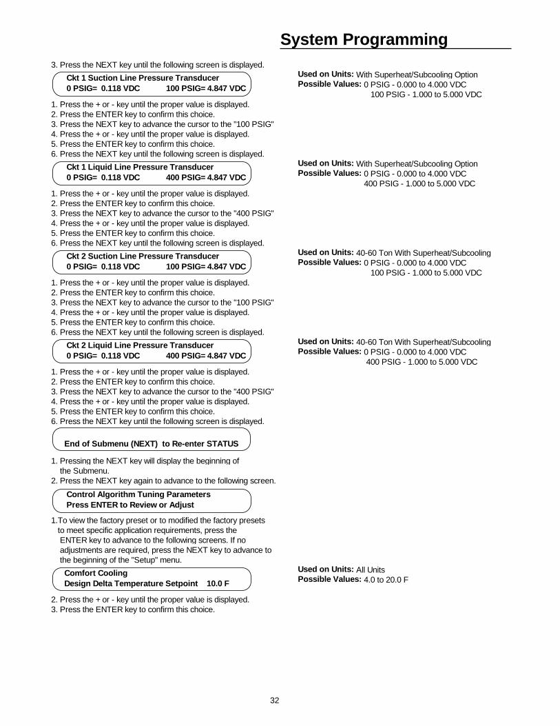
32
System Programming3. Press the NEXT key until the following screen is displayed.
Used on Units: With Superheat/Subcooling OptionPossible Values: 0 PSIG - 0.000 to 4.000 VDC 100 PSIG - 1.000 to 5.000 VDC
1. Press the + or - key until the proper value is displayed.2. Press the ENTER key to confirm this choice.3. Press the NEXT key to advance the cursor to the "100 PSIG"4. Press the + or - key until the proper value is displayed.5. Press the ENTER key to confirm this choice.6. Press the NEXT key until the following screen is displayed.
Used on Units: With Superheat/Subcooling OptionPossible Values: 0 PSIG - 0.000 to 4.000 VDC 400 PSIG - 1.000 to 5.000 VDC
1. Press the + or - key until the proper value is displayed.2. Press the ENTER key to confirm this choice.3. Press the NEXT key to advance the cursor to the "400 PSIG"4. Press the + or - key until the proper value is displayed.5. Press the ENTER key to confirm this choice.6. Press the NEXT key until the following screen is displayed.
Used on Units: 40-60 Ton With Superheat/SubcoolingPossible Values: 0 PSIG - 0.000 to 4.000 VDC 100 PSIG - 1.000 to 5.000 VDC
1. Press the + or - key until the proper value is displayed.2. Press the ENTER key to confirm this choice.3. Press the NEXT key to advance the cursor to the "100 PSIG"4. Press the + or - key until the proper value is displayed.5. Press the ENTER key to confirm this choice.6. Press the NEXT key until the following screen is displayed.
Used on Units: 40-60 Ton With Superheat/SubcoolingPossible Values: 0 PSIG - 0.000 to 4.000 VDC 400 PSIG - 1.000 to 5.000 VDC
1. Press the + or - key until the proper value is displayed.2. Press the ENTER key to confirm this choice.3. Press the NEXT key to advance the cursor to the "400 PSIG"4. Press the + or - key until the proper value is displayed.5. Press the ENTER key to confirm this choice.6. Press the NEXT key until the following screen is displayed.
1. Pressing the NEXT key will display the beginning of the Submenu.2. Press the NEXT key again to advance to the following screen.
1.To view the factory preset or to modified the factory presets to meet specific application requirements, press the ENTER key to advance to the following screens. If no adjustments are required, press the NEXT key to advance to the beginning of the "Setup" menu.
Used on Units: All UnitsPossible Values: 4.0 to 20.0 F
2. Press the + or - key until the proper value is displayed.3. Press the ENTER key to confirm this choice.
End of Submenu (NEXT) to Re-enter STATUS
Control Algorithm Tuning Parameters Press ENTER to Review or Adjust
Comfort Cooling Design Delta Temperature Setpoint 10.0 F
Ckt 1 Suction Line Pressure Transducer 0 PSIG= 0.118 VDC 100 PSIG= 4.847 VDC
Ckt 1 Liquid Line Pressure Transducer 0 PSIG= 0.118 VDC 400 PSIG= 4.847 VDC
Ckt 2 Suction Line Pressure Transducer 0 PSIG= 0.118 VDC 100 PSIG= 4.847 VDC
Ckt 2 Liquid Line Pressure Transducer 0 PSIG= 0.118 VDC 400 PSIG= 4.847 VDC
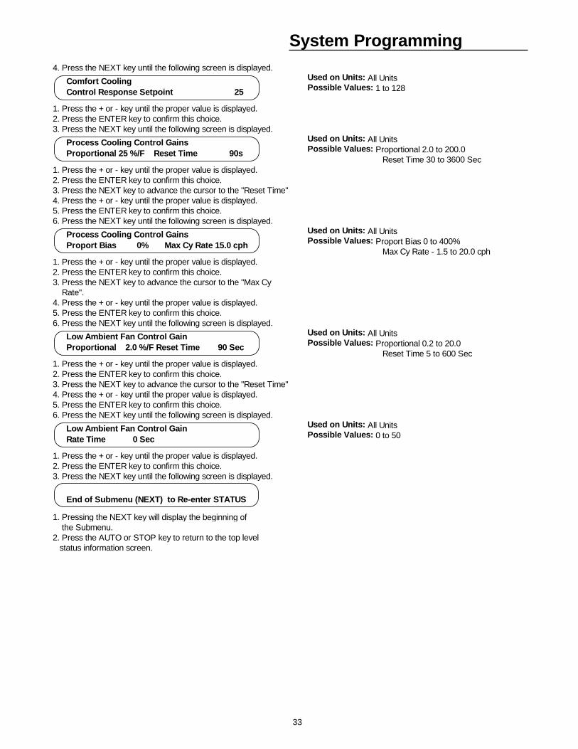
33
System Programming4. Press the NEXT key until the following screen is displayed.
Used on Units: All UnitsPossible Values: 1 to 128
1. Press the + or - key until the proper value is displayed.2. Press the ENTER key to confirm this choice.3. Press the NEXT key until the following screen is displayed.
Used on Units: All UnitsPossible Values: Proportional 2.0 to 200.0 Reset Time 30 to 3600 Sec
1. Press the + or - key until the proper value is displayed.2. Press the ENTER key to confirm this choice.3. Press the NEXT key to advance the cursor to the "Reset Time"4. Press the + or - key until the proper value is displayed.5. Press the ENTER key to confirm this choice.6. Press the NEXT key until the following screen is displayed.
Used on Units: All UnitsPossible Values: Proport Bias 0 to 400% Max Cy Rate - 1.5 to 20.0 cph
1. Press the + or - key until the proper value is displayed.2. Press the ENTER key to confirm this choice.3. Press the NEXT key to advance the cursor to the "Max Cy Rate".4. Press the + or - key until the proper value is displayed.5. Press the ENTER key to confirm this choice.6. Press the NEXT key until the following screen is displayed.
Used on Units: All UnitsPossible Values: Proportional 0.2 to 20.0 Reset Time 5 to 600 Sec
1. Press the + or - key until the proper value is displayed.2. Press the ENTER key to confirm this choice.3. Press the NEXT key to advance the cursor to the "Reset Time"4. Press the + or - key until the proper value is displayed.5. Press the ENTER key to confirm this choice.6. Press the NEXT key until the following screen is displayed.
Used on Units: All UnitsPossible Values: 0 to 50
1. Press the + or - key until the proper value is displayed.2. Press the ENTER key to confirm this choice.3. Press the NEXT key until the following screen is displayed.
1. Pressing the NEXT key will display the beginning of the Submenu.2. Press the AUTO or STOP key to return to the top level status information screen.
Comfort Cooling Control Response Setpoint 25
Process Cooling Control Gains Proportional 25 %/F Reset Time 90s
Process Cooling Control Gains Proport Bias 0% Max Cy Rate 15.0 cph
Low Ambient Fan Control Gain Proportional 2.0 %/F Reset Time 90 Sec
Low Ambient Fan Control Gain Rate Time 0 Sec
End of Submenu (NEXT) to Re-enter STATUS
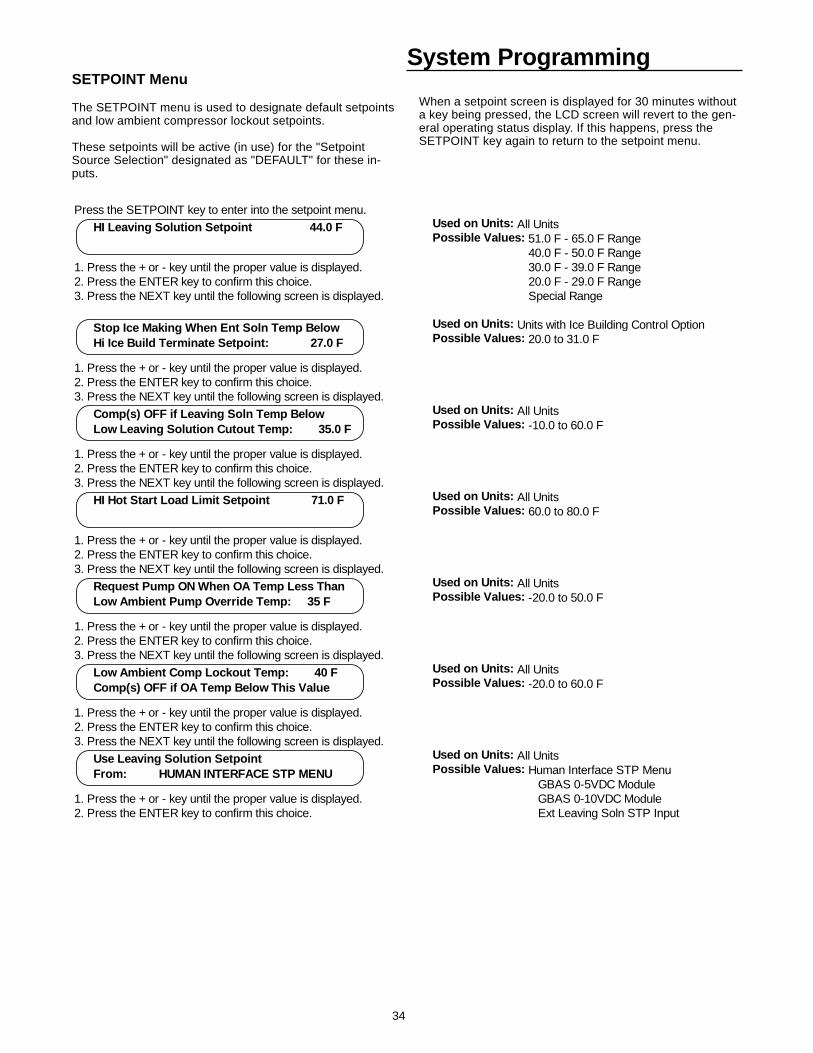
34
System ProgrammingSETPOINT Menu
The SETPOINT menu is used to designate default setpointsand low ambient compressor lockout setpoints.
These setpoints will be active (in use) for the "SetpointSource Selection" designated as "DEFAULT" for these in-puts.
When a setpoint screen is displayed for 30 minutes withouta key being pressed, the LCD screen will revert to the gen-eral operating status display. If this happens, press theSETPOINT key again to return to the setpoint menu.
Press the SETPOINT key to enter into the setpoint menu.Used on Units: All UnitsPossible Values: 51.0 F - 65.0 F Range 40.0 F - 50.0 F Range
1. Press the + or - key until the proper value is displayed. 30.0 F - 39.0 F Range2. Press the ENTER key to confirm this choice. 20.0 F - 29.0 F Range3. Press the NEXT key until the following screen is displayed. Special Range
Used on Units: Units with Ice Building Control OptionPossible Values: 20.0 to 31.0 F
1. Press the + or - key until the proper value is displayed.2. Press the ENTER key to confirm this choice.3. Press the NEXT key until the following screen is displayed.
Used on Units: All UnitsPossible Values: -10.0 to 60.0 F
1. Press the + or - key until the proper value is displayed.2. Press the ENTER key to confirm this choice.3. Press the NEXT key until the following screen is displayed.
Used on Units: All UnitsPossible Values: 60.0 to 80.0 F
1. Press the + or - key until the proper value is displayed.2. Press the ENTER key to confirm this choice.3. Press the NEXT key until the following screen is displayed.
Used on Units: All UnitsPossible Values: -20.0 to 50.0 F
1. Press the + or - key until the proper value is displayed.2. Press the ENTER key to confirm this choice.3. Press the NEXT key until the following screen is displayed.
Used on Units: All UnitsPossible Values: -20.0 to 60.0 F
1. Press the + or - key until the proper value is displayed.2. Press the ENTER key to confirm this choice.3. Press the NEXT key until the following screen is displayed.
Used on Units: All UnitsPossible Values: Human Interface STP Menu GBAS 0-5VDC Module
1. Press the + or - key until the proper value is displayed. GBAS 0-10VDC Module2. Press the ENTER key to confirm this choice. Ext Leaving Soln STP Input
HI Leaving Solution Setpoint 44.0 F
Stop Ice Making When Ent Soln Temp Below Hi Ice Build Terminate Setpoint: 27.0 F
Comp(s) OFF if Leaving Soln Temp Below Low Leaving Solution Cutout Temp: 35.0 F
HI Hot Start Load Limit Setpoint 71.0 F
Request Pump ON When OA Temp Less Than Low Ambient Pump Override Temp: 35 F
Low Ambient Comp Lockout Temp: 40 F Comp(s) OFF if OA Temp Below This Value
Use Leaving Solution Setpoint From: HUMAN INTERFACE STP MENU
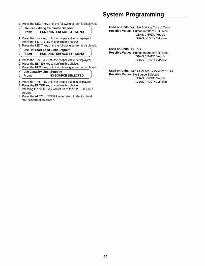
35
System Programming3. Press the NEXT key until the following screen is displayed.
Used on Units: With Ice Building Control OptionPossible Values: Human Interface STP Menu GBAS 0-5VDC Module
1. Press the + or - key until the proper value is displayed. GBAS 0-10VDC Module2. Press the ENTER key to confirm this choice.3. Press the NEXT key until the following screen is displayed.
Used on Units: All UnitsPossible Values: Human Interface STP Menu GBAS 0-5VDC Module
1. Press the + or - key until the proper value is displayed. GBAS 0-10VDC Module2. Press the ENTER key to confirm this choice.3. Press the NEXT key until the following screen is displayed.
Used on Units: With GBAS5V, GBAS10V or TCIPossible Values: No Source Selected GBAS 0-5VDC Module
1. Press the + or - key until the proper value is displayed. GBAS 0-10VDC Module2. Press the ENTER key to confirm this choice.3. Pressing the NEXT key will return to the 1st SETPOINT screen. 4. Press the AUTO or STOP key to return to the top level status information screen.
Use Ice Building Terminate Setpoint From: HUMAN INTERFACE STP MENU
Use Hot Start Load Limit Setpoint From: HUMAN INTERFACE STP MENU
Use Capacity Limit Setpoint From: NO SOURCE SELECTED
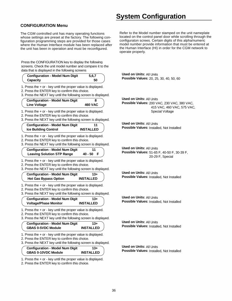
36
System ConfigurationCONFIGURATION Menu
The CGM controlled unit has many operating functionswhose settings are preset at the factory. The following con-figuration programming steps are provided for those caseswhere the Human Interface module has been replaced afterthe unit has been in operation and must be reconfigured.
Refer to the Model number stamped on the unit nameplatelocated on the control panel door while scrolling through theconfiguraton screes. Certain digits of this alpha/numericmodel number provide information that must be entered atthe Human Interface (HI) in order for the CGM network tooperate properly.
Press the CONFIGURATION key to display the followingscreens. Check the unit model number and compare it to thedata that is displayed in the following screens
Used on Units: All UnitsPossible Values: 20, 25, 30, 40, 50, 60
1. Press the + or - key until the proper value is displayed.2. Press the ENTER key to confirm this choice.3. Press the NEXT key until the following screen is displayed.
Used on Units: All UnitsPossible Values: 200 VAC, 230 VAC, 380 VAC, 415 VAC, 460 VAC, 575 VAC,
1. Press the + or - key until the proper value is displayed. Special Voltage2. Press the ENTER key to confirm this choice.3. Press the NEXT key until the following screen is displayed.
Used on Units: All UnitsPossible Values: Installed, Not Installed
1. Press the + or - key until the proper value is displayed.2. Press the ENTER key to confirm this choice.3. Press the NEXT key until the following screen is displayed.
Used on Units: All UnitsPossible Values: 51-65 F, 40-50 F, 30-39 F, 20-29 F, Special
1. Press the + or - key until the proper value is displayed.2. Press the ENTER key to confirm this choice.3. Press the NEXT key until the following screen is displayed.
Used on Units: All UnitsPossible Values: Installed, Not Installed
1. Press the + or - key until the proper value is displayed.2. Press the ENTER key to confirm this choice.3. Press the NEXT key until the following screen is displayed.
Used on Units: All UnitsPossible Values: Installed, Not Installed
1. Press the + or - key until the proper value is displayed.2. Press the ENTER key to confirm this choice.3. Press the NEXT key until the following screen is displayed.
Used on Units: All UnitsPossible Values: Installed, Not Installed
1. Press the + or - key until the proper value is displayed.2. Press the ENTER key to confirm this choice.3. Press the NEXT key until the following screen is displayed.
Used on Units: All UnitsPossible Values: Installed, Not Installed
1. Press the + or - key until the proper value is displayed.2. Press the ENTER key to confirm this choice.
Configuration - Model Num Digit 5,6,7 Capacity 50
Configuration - Model Num Digit 8 Line Voltage 460 VAC
Configuration - Model Num Digit 11 Ice Building Control INSTALLED
Configuration - Model Num Digit 11 Leaving Solution STP Range 40 - 50 F
Configuration - Model Num Digit 13+ Hot Gas Bypass Option INSTALLED
Configuration - Model Num Digit 13+ Voltage/Phase Monitor INSTALLED
Configuration - Model Num Digit 13+ GBAS 0-5VDC Module INSTALLED
Configuration - Model Num Digit 13+ GBAS 0-10VDC Module INSTALLED
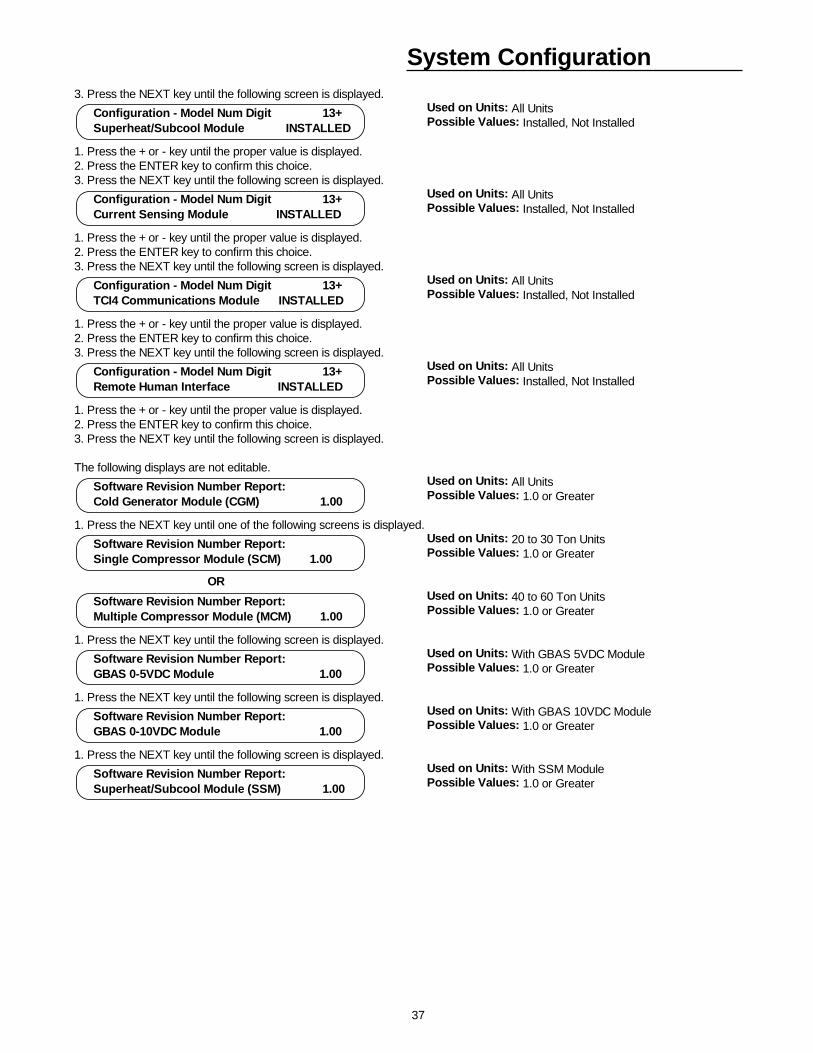
37
System Configuration3. Press the NEXT key until the following screen is displayed.
Used on Units: All UnitsPossible Values: Installed, Not Installed
1. Press the + or - key until the proper value is displayed.2. Press the ENTER key to confirm this choice.3. Press the NEXT key until the following screen is displayed.
Used on Units: All UnitsPossible Values: Installed, Not Installed
1. Press the + or - key until the proper value is displayed.2. Press the ENTER key to confirm this choice.3. Press the NEXT key until the following screen is displayed.
Used on Units: All UnitsPossible Values: Installed, Not Installed
1. Press the + or - key until the proper value is displayed.2. Press the ENTER key to confirm this choice.3. Press the NEXT key until the following screen is displayed.
Used on Units: All UnitsPossible Values: Installed, Not Installed
1. Press the + or - key until the proper value is displayed.2. Press the ENTER key to confirm this choice.3. Press the NEXT key until the following screen is displayed.
The following displays are not editable.Used on Units: All UnitsPossible Values: 1.0 or Greater
1. Press the NEXT key until one of the following screens is displayed. Used on Units: 20 to 30 Ton UnitsPossible Values: 1.0 or Greater
ORUsed on Units: 40 to 60 Ton UnitsPossible Values: 1.0 or Greater
1. Press the NEXT key until the following screen is displayed. Used on Units: With GBAS 5VDC ModulePossible Values: 1.0 or Greater
1. Press the NEXT key until the following screen is displayed. Used on Units: With GBAS 10VDC ModulePossible Values: 1.0 or Greater
1. Press the NEXT key until the following screen is displayed. Used on Units: With SSM ModulePossible Values: 1.0 or Greater
Configuration - Model Num Digit 13+ Superheat/Subcool Module INSTALLED
Configuration - Model Num Digit 13+ Current Sensing Module INSTALLED
Configuration - Model Num Digit 13+ TCI4 Communications Module INSTALLED
Configuration - Model Num Digit 13+ Remote Human Interface INSTALLED
Software Revision Number Report: Cold Generator Module (CGM) 1.00
Software Revision Number Report: Multiple Compressor Module (MCM) 1.00
Software Revision Number Report: GBAS 0-5VDC Module 1.00
Software Revision Number Report: GBAS 0-10VDC Module 1.00
Software Revision Number Report: Superheat/Subcool Module (SSM) 1.00
Software Revision Number Report: Single Compressor Module (SCM) 1.00
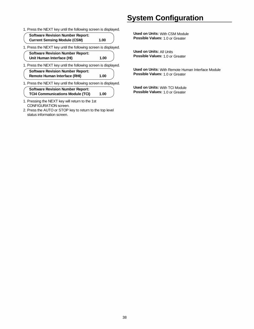
38
System Configuration1. Press the NEXT key until the following screen is displayed.
Used on Units: With CSM ModulePossible Values: 1.0 or Greater
1. Press the NEXT key until the following screen is displayed. Used on Units: All UnitsPossible Values: 1.0 or Greater
1. Press the NEXT key until the following screen is displayed. Used on Units: With Remote Human Interface ModulePossible Values: 1.0 or Greater
1. Press the NEXT key until the following screen is displayed. Used on Units: With TCI ModulePossible Values: 1.0 or Greater
1. Pressing the NEXT key will return to the 1st CONFIGURATION screen. 2. Press the AUTO or STOP key to return to the top level status information screen.
Software Revision Number Report: Current Sensing Module (CSM) 1.00
Software Revision Number Report: Unit Human Interface (HI) 1.00
Software Revision Number Report: TCI4 Communications Module (TCI) 1.00
Software Revision Number Report: Remote Human Interface (RHI) 1.00
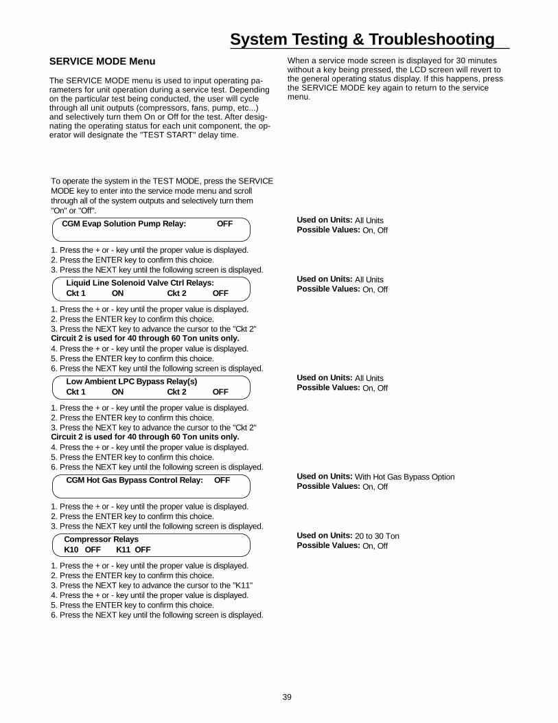
39
System Testing & Troubleshooting
To operate the system in the TEST MODE, press the SERVICEMODE key to enter into the service mode menu and scroll through all of the system outputs and selectively turn them"On" or "Off".
Used on Units: All UnitsPossible Values: On, Off
1. Press the + or - key until the proper value is displayed.2. Press the ENTER key to confirm this choice.3. Press the NEXT key until the following screen is displayed.
Used on Units: All UnitsPossible Values: On, Off
1. Press the + or - key until the proper value is displayed.2. Press the ENTER key to confirm this choice.3. Press the NEXT key to advance the cursor to the "Ckt 2"Circuit 2 is used for 40 through 60 Ton units only.4. Press the + or - key until the proper value is displayed.5. Press the ENTER key to confirm this choice.6. Press the NEXT key until the following screen is displayed.
Used on Units: With Hot Gas Bypass OptionPossible Values: On, Off
1. Press the + or - key until the proper value is displayed.2. Press the ENTER key to confirm this choice.3. Press the NEXT key until the following screen is displayed.
Used on Units: 20 to 30 TonPossible Values: On, Off
1. Press the + or - key until the proper value is displayed.2. Press the ENTER key to confirm this choice.3. Press the NEXT key to advance the cursor to the "K11"4. Press the + or - key until the proper value is displayed.5. Press the ENTER key to confirm this choice.6. Press the NEXT key until the following screen is displayed.
CGM Evap Solution Pump Relay: OFF
Liquid Line Solenoid Valve Ctrl Relays: Ckt 1 ON Ckt 2 OFF
CGM Hot Gas Bypass Control Relay: OFF
Low Ambient LPC Bypass Relay(s) Ckt 1 ON Ckt 2 OFF
Compressor Relays K10 OFF K11 OFF
SERVICE MODE Menu
The SERVICE MODE menu is used to input operating pa-rameters for unit operation during a service test. Dependingon the particular test being conducted, the user will cyclethrough all unit outputs (compressors, fans, pump, etc...)and selectively turn them On or Off for the test. After desig-nating the operating status for each unit component, the op-erator will designate the "TEST START" delay time.
When a service mode screen is displayed for 30 minuteswithout a key being pressed, the LCD screen will revert tothe general operating status display. If this happens, pressthe SERVICE MODE key again to return to the servicemenu.
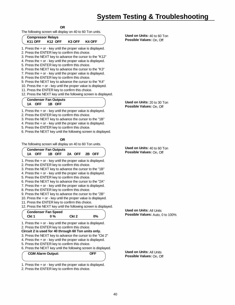
40
System Testing & TroubleshootingOR
The following screen will display on 40 to 60 Ton units.Used on Units: 40 to 60 TonPossible Values: On, Off
1. Press the + or - key until the proper value is displayed.2. Press the ENTER key to confirm this choice.3. Press the NEXT key to advance the cursor to the "K12"4. Press the + or - key until the proper value is displayed.5. Press the ENTER key to confirm this choice.6. Press the NEXT key to advance the cursor to the "K3"7. Press the + or - key until the proper value is displayed.8. Press the ENTER key to confirm this choice.9. Press the NEXT key to advance the cursor to the "K4"10. Press the + or - key until the proper value is displayed.11. Press the ENTER key to confirm this choice.12. Press the NEXT key until the following screen is displayed.
Used on Units: 20 to 30 TonPossible Values: On, Off
1. Press the + or - key until the proper value is displayed.2. Press the ENTER key to confirm this choice.3. Press the NEXT key to advance the cursor to the "1B"4. Press the + or - key until the proper value is displayed.5. Press the ENTER key to confirm this choice.6. Press the NEXT key until the following screen is displayed.
ORThe following screen will display on 40 to 60 Ton units.
Used on Units: 40 to 60 TonPossible Values: On, Off
1. Press the + or - key until the proper value is displayed.2. Press the ENTER key to confirm this choice.3. Press the NEXT key to advance the cursor to the "1B"4. Press the + or - key until the proper value is displayed.5. Press the ENTER key to confirm this choice.6. Press the NEXT key to advance the cursor to the "2A"7. Press the + or - key until the proper value is displayed.8. Press the ENTER key to confirm this choice.9. Press the NEXT key to advance the cursor to the "2B"10. Press the + or - key until the proper value is displayed.11. Press the ENTER key to confirm this choice.12. Press the NEXT key until the following screen is displayed.
Used on Units: All UnitsPossible Values: Auto, 0 to 100%
1. Press the + or - key until the proper value is displayed.2. Press the ENTER key to confirm this choice.Circuit 2 is used for 40 through 60 Ton units only.3. Press the NEXT key to advance the cursor to the "Ckt 2"4. Press the + or - key until the proper value is displayed.5. Press the ENTER key to confirm this choice.6. Press the NEXT key until the following screen is displayed.
Used on Units: All UnitsPossible Values: On, Off
1. Press the + or - key until the proper value is displayed.2. Press the ENTER key to confirm this choice.
Compressor Relays K11 OFF K12 OFF K3 OFF K4 OFF
Condenser Fan Outputs 1A OFF 1B OFF 2A OFF 2B OFF
Condenser Fan Speed Ckt 1 0 % Ckt 2 0%
CGM Alarm Output: OFF
Condenser Fan Outputs 1A OFF 1B OFF
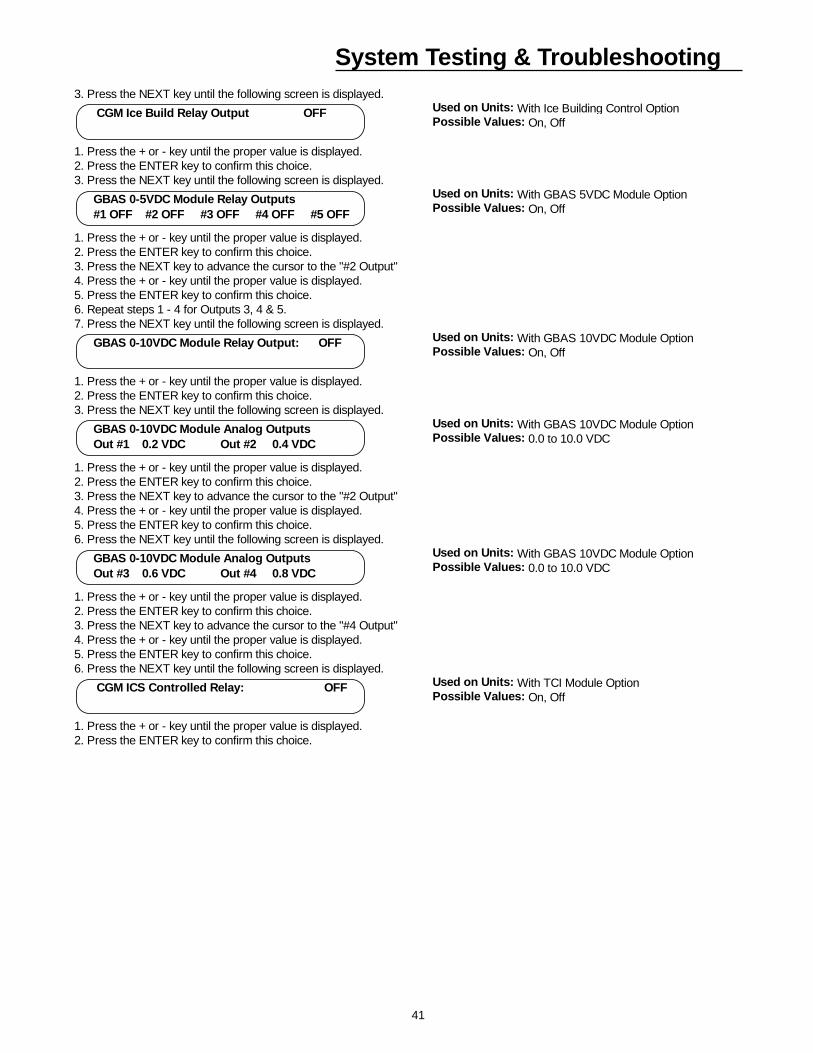
41
System Testing & Troubleshooting3. Press the NEXT key until the following screen is displayed.
Used on Units: With Ice Building Control OptionPossible Values: On, Off
1. Press the + or - key until the proper value is displayed.2. Press the ENTER key to confirm this choice.3. Press the NEXT key until the following screen is displayed.
Used on Units: With GBAS 5VDC Module OptionPossible Values: On, Off
1. Press the + or - key until the proper value is displayed.2. Press the ENTER key to confirm this choice.3. Press the NEXT key to advance the cursor to the "#2 Output"4. Press the + or - key until the proper value is displayed.5. Press the ENTER key to confirm this choice.6. Repeat steps 1 - 4 for Outputs 3, 4 & 5.7. Press the NEXT key until the following screen is displayed.
Used on Units: With GBAS 10VDC Module OptionPossible Values: On, Off
1. Press the + or - key until the proper value is displayed.2. Press the ENTER key to confirm this choice.3. Press the NEXT key until the following screen is displayed.
Used on Units: With GBAS 10VDC Module OptionPossible Values: 0.0 to 10.0 VDC
1. Press the + or - key until the proper value is displayed.2. Press the ENTER key to confirm this choice.3. Press the NEXT key to advance the cursor to the "#2 Output"4. Press the + or - key until the proper value is displayed.5. Press the ENTER key to confirm this choice.6. Press the NEXT key until the following screen is displayed.
Used on Units: With GBAS 10VDC Module OptionPossible Values: 0.0 to 10.0 VDC
1. Press the + or - key until the proper value is displayed.2. Press the ENTER key to confirm this choice.3. Press the NEXT key to advance the cursor to the "#4 Output"4. Press the + or - key until the proper value is displayed.5. Press the ENTER key to confirm this choice.6. Press the NEXT key until the following screen is displayed.
Used on Units: With TCI Module OptionPossible Values: On, Off
1. Press the + or - key until the proper value is displayed.2. Press the ENTER key to confirm this choice.
CGM Ice Build Relay Output OFF
GBAS 0-5VDC Module Relay Outputs #1 OFF #2 OFF #3 OFF #4 OFF #5 OFF
GBAS 0-10VDC Module Relay Output: OFF
GBAS 0-10VDC Module Analog Outputs Out #1 0.2 VDC Out #2 0.4 VDC
GBAS 0-10VDC Module Analog Outputs Out #3 0.6 VDC Out #4 0.8 VDC
CGM ICS Controlled Relay: OFF
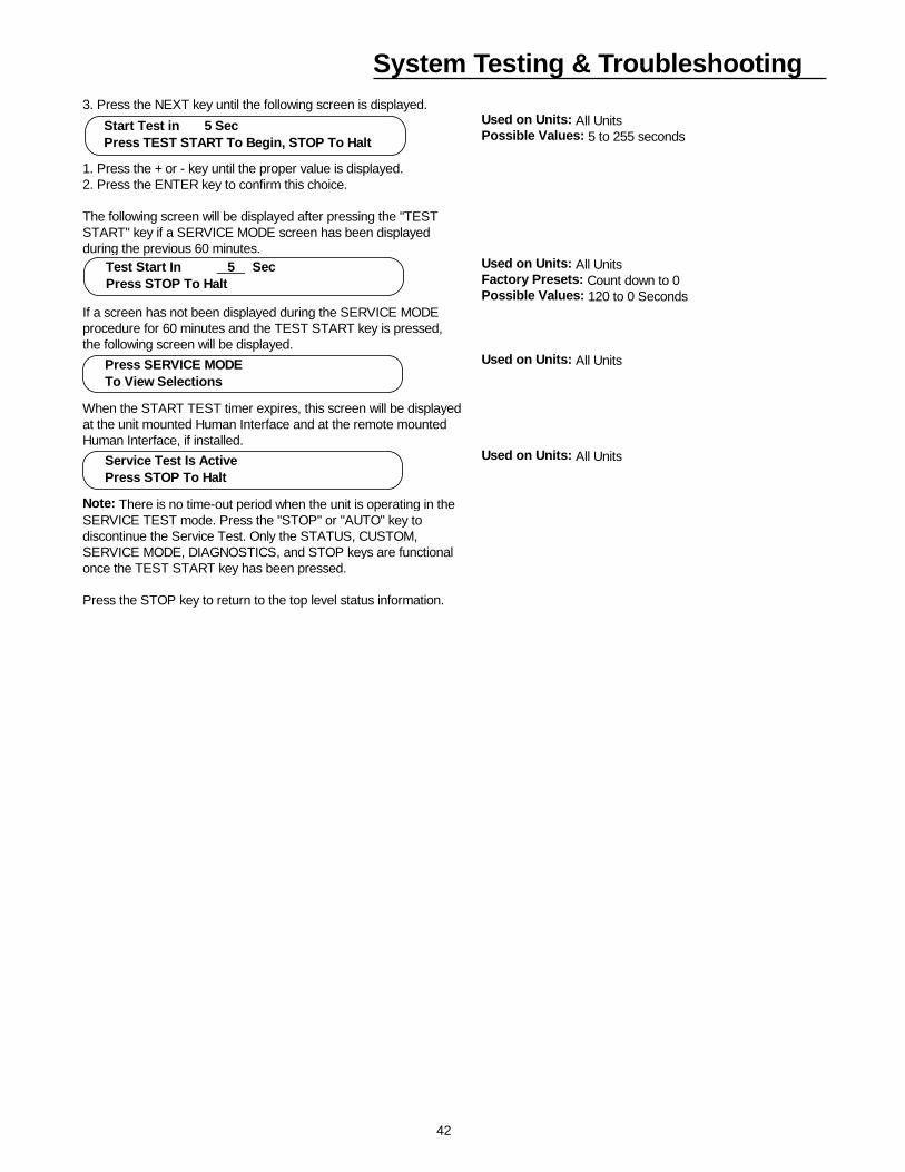
42
System Testing & Troubleshooting3. Press the NEXT key until the following screen is displayed.
Used on Units: All UnitsPossible Values: 5 to 255 seconds
1. Press the + or - key until the proper value is displayed.2. Press the ENTER key to confirm this choice.
The following screen will be displayed after pressing the "TESTSTART" key if a SERVICE MODE screen has been displayedduring the previous 60 minutes.
Used on Units: All UnitsFactory Presets: Count down to 0Possible Values: 120 to 0 Seconds
If a screen has not been displayed during the SERVICE MODEprocedure for 60 minutes and the TEST START key is pressed, the following screen will be displayed.
Used on Units: All Units
When the START TEST timer expires, this screen will be displayedat the unit mounted Human Interface and at the remote mountedHuman Interface, if installed.
Used on Units: All Units
Note: There is no time-out period when the unit is operating in theSERVICE TEST mode. Press the "STOP" or "AUTO" key todiscontinue the Service Test. Only the STATUS, CUSTOM, SERVICE MODE, DIAGNOSTICS, and STOP keys are functionalonce the TEST START key has been pressed.
Press the STOP key to return to the top level status information.
Start Test in 5 Sec Press TEST START To Begin, STOP To Halt
Test Start In 5 Sec Press STOP To Halt
Press SERVICE MODE To View Selections
Service Test Is Active Press STOP To Halt
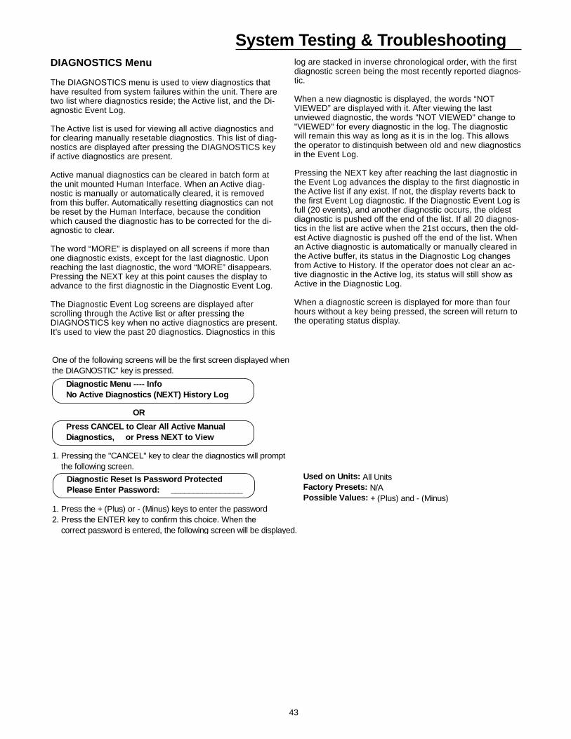
43
System Testing & TroubleshootingDIAGNOSTICS Menu
The DIAGNOSTICS menu is used to view diagnostics thathave resulted from system failures within the unit. There aretwo list where diagnostics reside; the Active list, and the Di-agnostic Event Log.
The Active list is used for viewing all active diagnostics andfor clearing manually resetable diagnostics. This list of diag-nostics are displayed after pressing the DIAGNOSTICS keyif active diagnostics are present.
Active manual diagnostics can be cleared in batch form atthe unit mounted Human Interface. When an Active diag-nostic is manually or automatically cleared, it is removedfrom this buffer. Automatically resetting diagnostics can notbe reset by the Human Interface, because the conditionwhich caused the diagnostic has to be corrected for the di-agnostic to clear.
The word “MORE” is displayed on all screens if more thanone diagnostic exists, except for the last diagnostic. Uponreaching the last diagnostic, the word “MORE” disappears.Pressing the NEXT key at this point causes the display toadvance to the first diagnostic in the Diagnostic Event Log.
The Diagnostic Event Log screens are displayed afterscrolling through the Active list or after pressing theDIAGNOSTICS key when no active diagnostics are present.It’s used to view the past 20 diagnostics. Diagnostics in this
log are stacked in inverse chronological order, with the firstdiagnostic screen being the most recently reported diagnos-tic.
When a new diagnostic is displayed, the words “NOTVIEWED” are displayed with it. After viewing the lastunviewed diagnostic, the words "NOT VIEWED" change to"VIEWED" for every diagnostic in the log. The diagnosticwill remain this way as long as it is in the log. This allowsthe operator to distinquish between old and new diagnosticsin the Event Log.
Pressing the NEXT key after reaching the last diagnostic inthe Event Log advances the display to the first diagnostic inthe Active list if any exist. If not, the display reverts back tothe first Event Log diagnostic. If the Diagnostic Event Log isfull (20 events), and another diagnostic occurs, the oldestdiagnostic is pushed off the end of the list. If all 20 diagnos-tics in the list are active when the 21st occurs, then the old-est Active diagnostic is pushed off the end of the list. Whenan Active diagnostic is automatically or manually cleared inthe Active buffer, its status in the Diagnostic Log changesfrom Active to History. If the operator does not clear an ac-tive diagnostic in the Active log, its status will still show asActive in the Diagnostic Log.
When a diagnostic screen is displayed for more than fourhours without a key being pressed, the screen will return tothe operating status display.
One of the following screens will be the first screen displayed whenthe DIAGNOSTIC" key is pressed.
OR
1. Pressing the "CANCEL" key to clear the diagnostics will prompt the following screen.
Used on Units: All UnitsFactory Presets: N/APossible Values: + (Plus) and - (Minus)
1. Press the + (Plus) or - (Minus) keys to enter the password2. Press the ENTER key to confirm this choice. When the correct password is entered, the following screen will be displayed.
Diagnostic Reset Is Password Protected Please Enter Password: ________________
Diagnostic Menu ---- Info No Active Diagnostics (NEXT) History Log
Press CANCEL to Clear All Active Manual Diagnostics, or Press NEXT to View
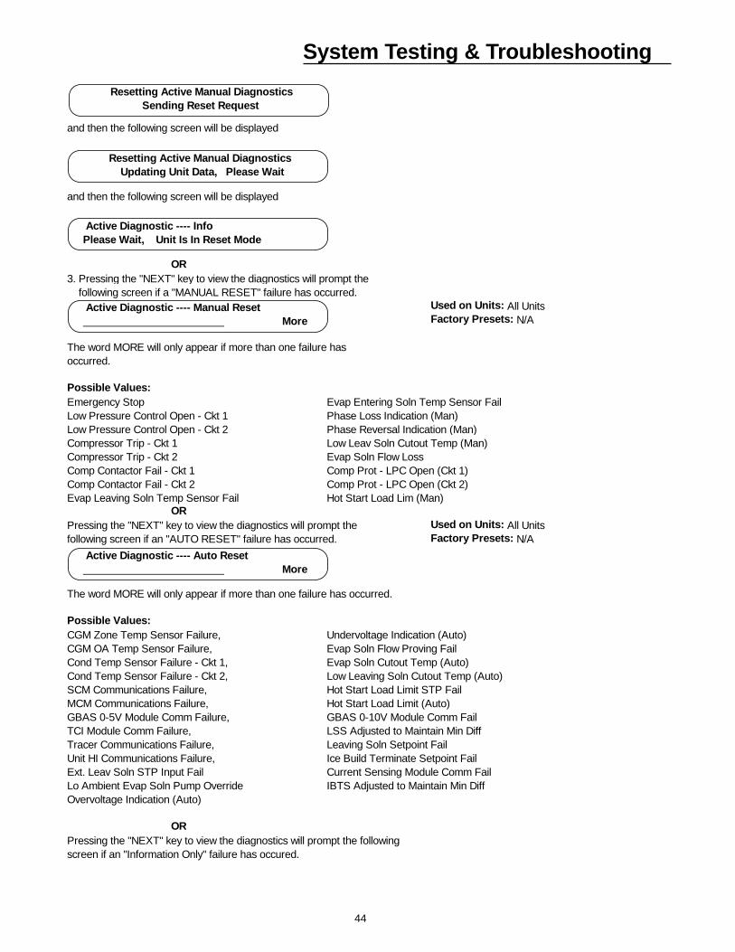
44
System Testing & Troubleshooting
and then the following screen will be displayed
and then the following screen will be displayed
OR3. Pressing the "NEXT" key to view the diagnostics will prompt the following screen if a "MANUAL RESET" failure has occurred.
Used on Units: All UnitsFactory Presets: N/A
The word MORE will only appear if more than one failure hasoccurred.
Possible Values:Emergency Stop Evap Entering Soln Temp Sensor FailLow Pressure Control Open - Ckt 1 Phase Loss Indication (Man)Low Pressure Control Open - Ckt 2 Phase Reversal Indication (Man)Compressor Trip - Ckt 1 Low Leav Soln Cutout Temp (Man)Compressor Trip - Ckt 2 Evap Soln Flow LossComp Contactor Fail - Ckt 1 Comp Prot - LPC Open (Ckt 1)Comp Contactor Fail - Ckt 2 Comp Prot - LPC Open (Ckt 2)Evap Leaving Soln Temp Sensor Fail Hot Start Load Lim (Man) ORPressing the "NEXT" key to view the diagnostics will prompt the Used on Units: All Unitsfollowing screen if an "AUTO RESET" failure has occurred. Factory Presets: N/A
The word MORE will only appear if more than one failure has occurred.
Possible Values: CGM Zone Temp Sensor Failure, Undervoltage Indication (Auto)CGM OA Temp Sensor Failure, Evap Soln Flow Proving FailCond Temp Sensor Failure - Ckt 1, Evap Soln Cutout Temp (Auto)Cond Temp Sensor Failure - Ckt 2, Low Leaving Soln Cutout Temp (Auto)SCM Communications Failure, Hot Start Load Limit STP FailMCM Communications Failure, Hot Start Load Limit (Auto)GBAS 0-5V Module Comm Failure, GBAS 0-10V Module Comm FailTCI Module Comm Failure, LSS Adjusted to Maintain Min DiffTracer Communications Failure, Leaving Soln Setpoint FailUnit HI Communications Failure, Ice Build Terminate Setpoint FailExt. Leav Soln STP Input Fail Current Sensing Module Comm FailLo Ambient Evap Soln Pump Override IBTS Adjusted to Maintain Min DiffOvervoltage Indication (Auto)
ORPressing the "NEXT" key to view the diagnostics will prompt the following screen if an "Information Only" failure has occured.
Active Diagnostic ---- Auto Reset More
Resetting Active Manual Diagnostics Updating Unit Data, Please Wait
Resetting Active Manual Diagnostics Sending Reset Request
Active Diagnostic ---- Info Please Wait, Unit Is In Reset Mode
Active Diagnostic ---- Manual Reset More
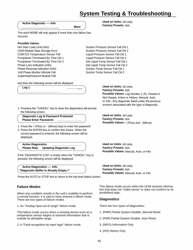
45
System Testing & TroubleshootingUsed on Units: All UnitsFactory Presets: N/A
The word MORE will only appear if more than one failure hasoccured.
Possible Values:Hot Start Load Limit (Info) Suction Pressure Sensor Fail Ckt 1CGM Module Data Storage Error Suction Pressure Sensor Fail Ckt 2CGM ICS Temperature Sensor Fail Liquid Pressure Sensor Fail Ckt 1Pumpdown Terminated By Time Ckt 1 Liquid Pressure Sensor Fail Ckt 2Pumpdown Terminated By Time Ckt 2 Sat Liquid Temp Sensor Fail Ckt 1Phase Loss Indication (Info) Sat Liquid Temp Sensor Fail Ckt 2Phase Reversal Indication (Info) Suction Temp Sensor Fail Ckt 1Volt Phase Monitor Module Fail Suction Temp Sensor Fail Ckt 2Superheat/Subcool Module Fail
and then the following screen will be displayedUsed on Units: All UnitsFactory Presets: N/APossible Values: Log Number 1-20, Viewed orNot Viewed, Active or History, Manual, Auto,or Info., Any diagnostic listed under the previousscreens associated with the type of diagnostic.
1. Pressing the "CANCEL" key to clear the diagnostics will prompt the following screen.
Used on Units: All UnitsFactory Presets: N/APossible Values: + (Plus) and - (Minus)
1. Press the + (Plus) or - (Minus) keys to enter the password2. Press the ENTER key to confirm this choice. When the correct password is entered, the following screen will be displayed.
Used on Units: All UnitsFactory Presets: N/APossible Values: Manual, Auto, or Info
If the "DIAGNOSTIC LOG" is empty when the "CANCEL" key ispressed, the following screen will be displayed.
Used on Units: All UnitsFactory Presets: N/APossible Values: Manual, Auto, or Info
Press the AUTO or STOP key to return to the top level status screen.
Active Diagnostic ---- Info More
Log 1 __________ _________________________
Diagnostic Log Is Password Protected Please Enter Password: ________________
Active Diagnostics ____________________ Please Wait, Updating Diagnostic Log
Active Diagnostics ---- Info"Diagnostic Buffer Is Already Empty !"
Failure Modes
When any condition results in the unit's unability to performa normal function, it is said to have entered a failure mode.There are two types of failure modes.
1. An "Analog input out of range" failure mode.
This failure mode occurs when a sensing device such as atemperature sensor begins to transmit information that isoutside its allowable range.
2. A "Fault recognition by input logic" failure mode.
This failure mode occurs when the UCM receives informa-tion that does not "make sense" or does not conform to itspredefined logic.
Diagnostics
There are four types of diagnostics:
1. (PMR) Partial System Disable, Manual Reset
2. (PAR) Partial System Disable, Auto Reset
3. (INFO) Information Only
4. (HO) History Only
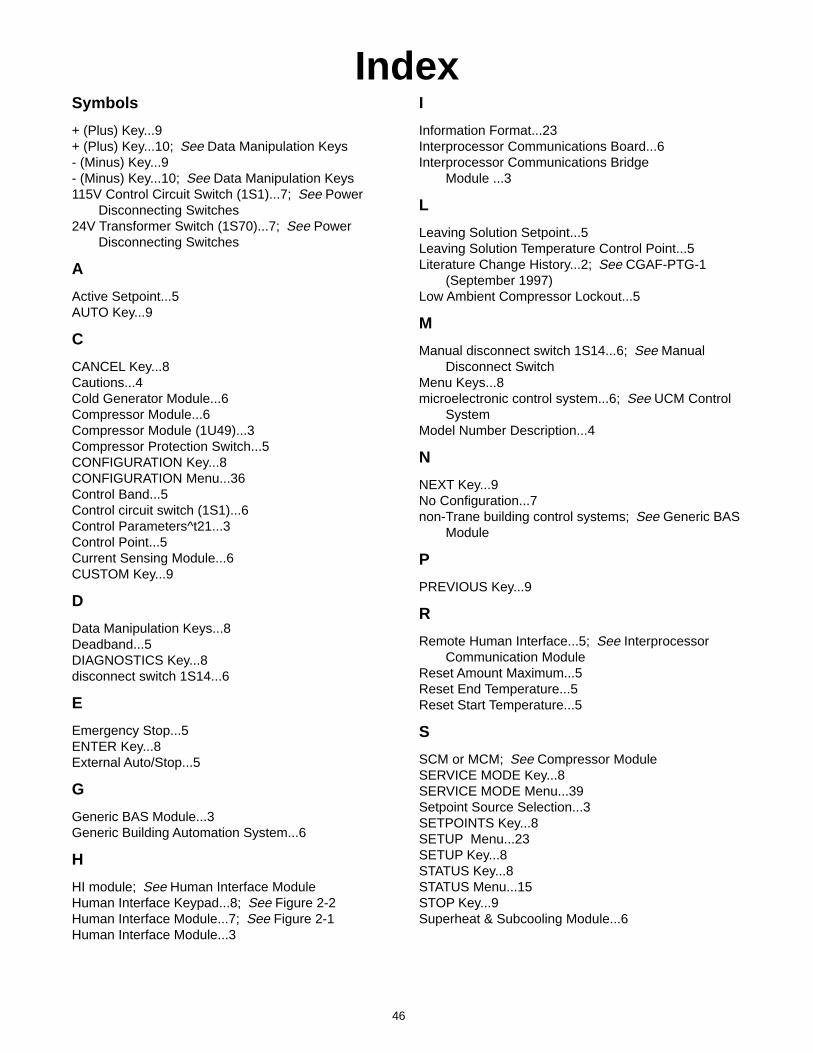
46
IndexI
Information Format...23Interprocessor Communications Board...6Interprocessor Communications Bridge
Module ...3
L
Leaving Solution Setpoint...5Leaving Solution Temperature Control Point...5Literature Change History...2; See CGAF-PTG-1
(September 1997)Low Ambient Compressor Lockout...5
M
Manual disconnect switch 1S14...6; See ManualDisconnect Switch
Menu Keys...8microelectronic control system...6; See UCM Control
SystemModel Number Description...4
N
NEXT Key...9No Configuration...7non-Trane building control systems; See Generic BAS
Module
P
PREVIOUS Key...9
R
Remote Human Interface...5; See InterprocessorCommunication Module
Reset Amount Maximum...5Reset End Temperature...5Reset Start Temperature...5
S
SCM or MCM; See Compressor ModuleSERVICE MODE Key...8SERVICE MODE Menu...39Setpoint Source Selection...3SETPOINTS Key...8SETUP Menu...23SETUP Key...8STATUS Key...8STATUS Menu...15STOP Key...9Superheat & Subcooling Module...6
Symbols
+ (Plus) Key...9+ (Plus) Key...10; See Data Manipulation Keys- (Minus) Key...9- (Minus) Key...10; See Data Manipulation Keys115V Control Circuit Switch (1S1)...7; See Power
Disconnecting Switches24V Transformer Switch (1S70)...7; See Power
Disconnecting Switches
A
Active Setpoint...5AUTO Key...9
C
CANCEL Key...8Cautions...4Cold Generator Module...6Compressor Module...6Compressor Module (1U49)...3Compressor Protection Switch...5CONFIGURATION Key...8CONFIGURATION Menu...36Control Band...5Control circuit switch (1S1)...6Control Parameters^t21...3Control Point...5Current Sensing Module...6CUSTOM Key...9
D
Data Manipulation Keys...8Deadband...5DIAGNOSTICS Key...8disconnect switch 1S14...6
E
Emergency Stop...5ENTER Key...8External Auto/Stop...5
G
Generic BAS Module...3Generic Building Automation System...6
H
HI module; See Human Interface ModuleHuman Interface Keypad...8; See Figure 2-2Human Interface Module...7; See Figure 2-1Human Interface Module...3
47
T
TEST START Key (SERVICE)...9Trane Communications Interface Module...6Trane Communications Interface
Module ...3Trane integrated comfort systems; See Trane Com-
munications Interface ModuleTransformer switch 1S70...6
U
Unit Control Module...5Unit Nameplate...4Unit Operation Keys...9Unit Status (Unit Off or Stopped)...7Unit Status (Unit On)...7
W
Warnings...4

48


![Tigran PTG [Porous Titanium Granules] for Bone ... PTG for bone regeneration and... · BONE REGENERATION AND IMPLANT OSSEOINTEGRATION 3 Tigran™ PTG (Porous Titanium Granules) 80%](https://img.pdfslide.us/doc/110x75/5a74c5737f8b9a63638bf52d/tigran-ptg-porous-titanium-granules-for-bone-ptg-for-bone-regeneration-and.jpg)