Embed Size (px)
Citation preview
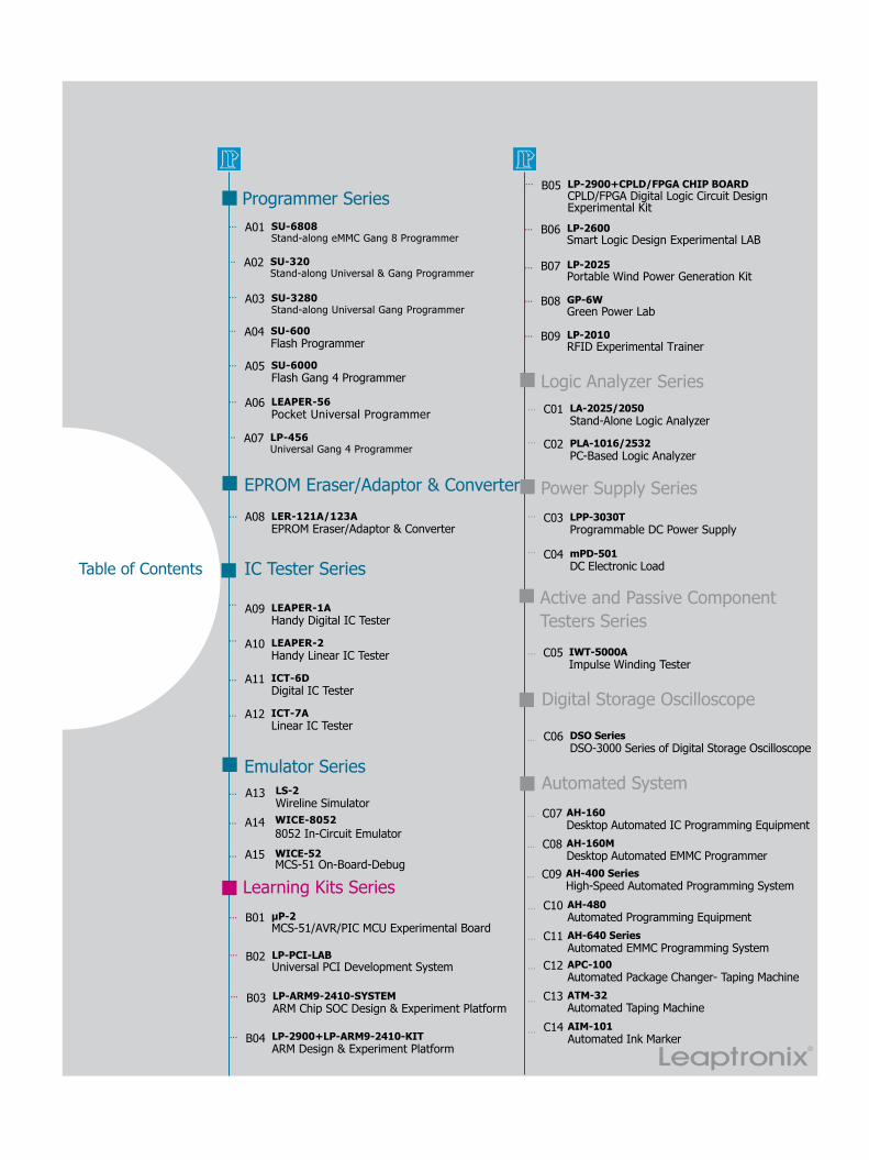
Table of Contents
SU-6808 Stand-along eMMC Gang 8 Programmer
SU-3280Stand-along Universal Gang Programmer
SU-320Stand-along Universal & Gang Programmer
SU-6000 Flash Gang 4 Programmer
SU-600 Flash Programmer
LP-456Universal Gang 4 Programmer
LEAPER-56 Pocket Universal Programmer
Programmer Series...
...
...
...
...
...
...
A01
A03
A02
A05
A04
A07
A06
A08
A09
A10
A11
A12
A14
A15
IC Tester Series
LEAPER-1AHandy Digital IC Tester
LEAPER-2 Handy Linear IC Tester
ICT-6D Digital IC Tester
ICT-7A Linear IC Tester
Emulator Series
WICE-8052 8052 In-Circuit Emulator WICE-52MCS-51 On-Board-Debug
...
...
EPROM Eraser/Adaptor & Converter
LER-121A/123AEPROM Eraser/Adaptor & Converter
...
...
...
Learning Kits Series
...
...
...
...
LP-PCI-LAB Universal PCI Development System
LP-ARM9-2410-SYSTEMARM Chip SOC Design & Experiment Platform
LP-2900+LP-ARM9-2410-KITARM Design & Experiment Platform
LP-2900+CPLD/FPGA CHIP BOARDCPLD/FPGA Digital Logic Circuit Design Experimental Kit
LP-2600 Smart Logic Design Experimental LAB
μP-2 MCS-51/AVR/PIC MCU Experimental Board
LP-2025 Portable Wind Power Generation Kit
GP-6W Green Power Lab
LP-2010 RFID Experimental Trainer
B02
B03
B04
B05
B06
B01
B07
B08
B09
...
...
...
...
...
...
...
LA-2025/2050 Stand-Alone Logic Analyzer
PLA-1016/2532PC-Based Logic Analyzer
Logic Analyzer SeriesC01
C02
Power Supply SeriesLPP-3030TProgrammable DC Power Supply
mPD-501 DC Electronic Load
C03
C04
Automated System
Digital Storage Oscilloscope
DSO SeriesDSO-3000 Series of Digital Storage Oscilloscope
C06
...
...
...
...
IWT-5000A Impulse Winding Tester
Active and Passive ComponentTesters Series
...
...
...
...
C10
C09
C07
C12
C13
AH-480 Automated Programming Equipment
AH-400 Series High-Speed Automated Programming System
AH-160Desktop Automated IC Programming Equipment
APC-100Automated Package Changer- Taping MachineATM-32Automated Taping Machine
... C05
...
...
C14 AIM-101Automated Ink Marker
...
... C08 AH-160MDesktop Automated EMMC Programmer
... C11 AH-640 Series Automated EMMC Programming System
A13 LS-2Wireline Simulator
...
Programm
er Series
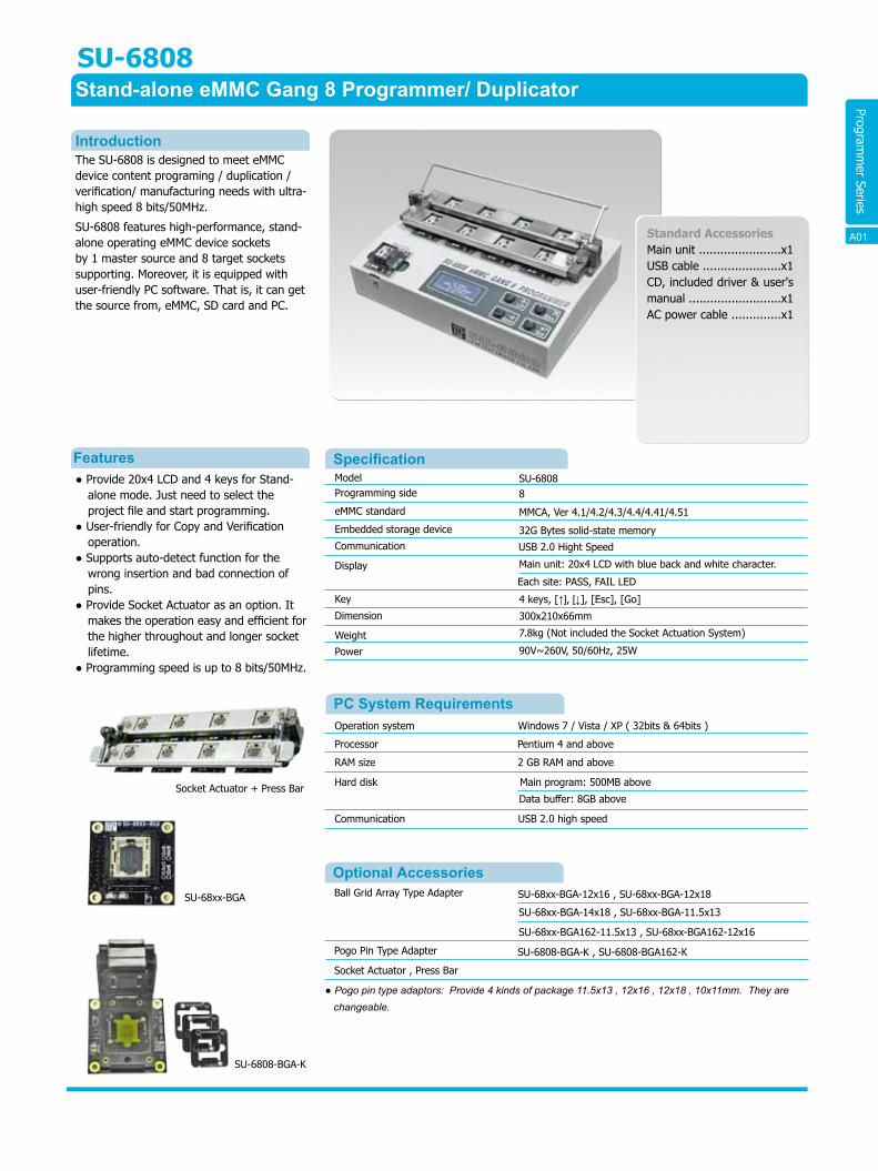
SU-6808 Stand-alone eMMC Gang 8 Programmer/ Duplicator
The SU-6808 is designed to meet eMMC device content programing / duplication / verification/ manufacturing needs with ultra-high speed 8 bits/50MHz.
SU-6808 features high-performance, stand-alone operating eMMC device sockets by 1 master source and 8 target sockets supporting. Moreover, it is equipped with user-friendly PC software. That is, it can get the source from, eMMC, SD card and PC.
● Provide 20x4 LCD and 4 keys for Stand-alone mode. Just need to select the project file and start programming.
● User-friendly for Copy and Verificationoperation.
● Supports auto-detect function for thewrong insertion and bad connection of pins.
● Provide Socket Actuator as an option. Itmakes the operation easy and efficient for the higher throughout and longer socket lifetime.
● Programming speed is up to 8 bits/50MHz.
Standard AccessoriesMain unit .......................x1USB cable ......................x1CD, included driver & user's manual ..........................x1AC power cable ..............x1
Introduction
Features SpecificationModel Programming side
eMMC standard
Embedded storage device
Communication
Display
Key
Dimension
Weight
Power
Operation system Windows 7 / Vista / XP ( 32bits & 64bits )
Processor Pentium 4 and above
RAM size 2 GB RAM and above
Hard disk Main program: 500MB above
Data buffer: 8GB above
Communication USB 2.0 high speed
Optional AccessoriesBall Grid Array Type Adapter SU-68xx-BGA-12x16 , SU-68xx-BGA-12x18
SU-68xx-BGA-14x18 , SU-68xx-BGA-11.5x13
SU-68xx-BGA162-11.5x13 , SU-68xx-BGA162-12x16
Pogo Pin Type Adapter SU-6808-BGA-K , SU-6808-BGA162-K
Socket Actuator , Press Bar
PC System Requirements
SU-68088
MMCA, Ver 4.1/4.2/4.3/4.4/4.41/4.51
32G Bytes solid-state memory
Main unit: 20x4 LCD with blue back and white character.
4 keys, [↑], [↓], [Esc], [Go]
300x210x66mm
7.8kg (Not included the Socket Actuation System)
90V~260V, 50/60Hz, 25W
USB 2.0 Hight Speed
Each site: PASS, FAIL LED
SU-6808-BGA-K
Socket Actuator + Press Bar
SU-68xx-BGA
● Pogo pin type adaptors: Provide 4 kinds of package 11.5x13 , 12x16 , 12x18 , 10x11mm. They are changeable.
A01
Programm
er Series
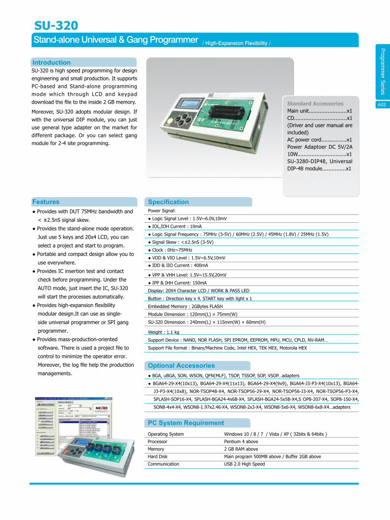
SU-320Stand-alone Universal & Gang Programmer
SU-320 is high speed programming for design engineering and small production. It supports PC-based and Stand-alone programming mode which through LCD and keypad download the file to the inside 2 GB memory.
Moreover, SU-320 adopts modular design. If with the universal DIP module, you can just use general type adapter on the market for different package. Or you can select gang module for 2-4 site programming.
● Provides with DUT 75MHz bandwidth and
< ±2.5nS signal skew.
● Provides the stand-alone mode operation.
Just use 5 keys and 20x4 LCD, you can
select a project and start to program.
● Portable and compact design allow you to
use everywhere.
● Provides IC insertion test and contact
check before programming. Under the
AUTO mode, just insert the IC, SU-320
will start the processes automatically.
● Provides high-expansion flexibility
modular design.It can use as single-
side universal programmer or SPI gang
programmer.
● Provides mass-production-oriented
software. There is used a project file to
control to minimize the operator error.
Moreover, the log file help the production
managements.
Standard AccessoriesMain unit........................x1CD.................................x1 (Driver and user manual are included)AC power cord................x1Power Adaptoer DC 5V/2A 10W...............................x1SU-3280-DIP48, Universal DIP-48 module...............x1
Introduction
Features
A05
/ High-Expansion Flexibility /
SpecificationPower Signal:
● Logic Signal Level : 1.5V~6.0V,10mV
● IOL,IOH Current : 10mA
● Logic Signal Frequency : 75MHz (3-5V) / 60MHz (2.5V) / 45MHz (1.8V) / 25MHz (1.5V)
● Signal Skew : <±2.5nS (3-5V)
● Clock : 0Hz~75MHz
● VDD & VIO Level : 1.5V~6.5V,10mV
● IDD & IIO Current : 400mA
● BGA, uBGA, SON, WSON, QFN(MLF), TSOP, TSSOP, SOP, VSOP…adapters
● BGA64-29-X4(10x13), BGA64-29-X4(11x13), BGA64-29-X4(9x9), BGA64-J3-P3-X4(10x13), BGA64-
J3-P3-X4(10x8), NOR-TSOP48-X4, NOR-TSOP56-29-X4, NOR-TSOP56-J3-X4, NOR-TSOP56-P3-X4,
SFLASH-SOP16-X4, SFLASH-BGA24-4x6B-X4, SFLASH-BGA24-5x5B-X4,S OP8-207-X4, SOP8-150-X4,
SON8-4x4-X4, WSON8-1.97x2.46-X4, WSON8-2x3-X4, WSON8-5x6-X4, WSON8-6x8-X4…adapters
PC System RequirementOperating System
Processor
Memory
Hard Disk
Communication
Windows 10 / 8 / 7 / Vista / XP ( 32bits & 64bits )
Pentium 4 above
2 GB RAM above
Main program 500MB above / Buffer 2GB above
USB 2.0 High Speed
Optional Accessories
● VPP & VHH Level: 1.5V~15.5V,20mV
● IPP & IHH Current: 150mA
Display: 20X4 Character LCD / WORK & PASS LED
Button : Direction key x 4. START key with light x 1
Embedded Memory : 2GBytes FLASH
Module Dimension : 120mm(L) × 75mm(W)
SU-320 Dimension : 240mm(L) × 115mm(W) × 60mm(H)
Weight : 1.1 kg
Support Device : NAND, NOR FLASH, SPI EPROM, EEPROM, MPU, MCU, CPLD, NV-RAM…
Support File format : Binary/Machine Code, Intel HEX, TEK HEX, Motorola HEX
A02
Programm
er Series
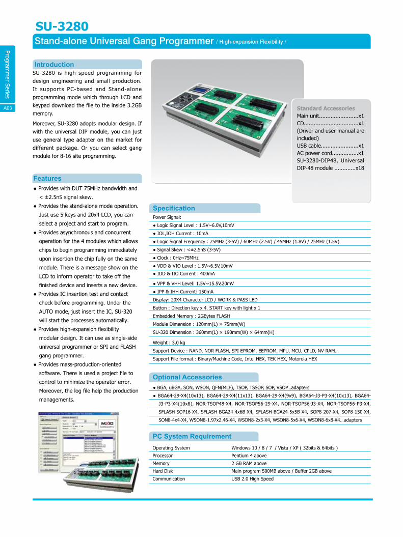
SU-3280Stand-alone Universal Gang Programmer
SU-3280 is high speed programming for design engineering and small production. It supports PC-based and Stand-alone programming mode which through LCD and keypad download the file to the inside 3.2GB memory.
Moreover, SU-3280 adopts modular design. If with the universal DIP module, you can just use general type adapter on the market for different package. Or you can select gang module for 8-16 site programming.
● Provides with DUT 75MHz bandwidth and
< ±2.5nS signal skew.
● Provides the stand-alone mode operation.
Just use 5 keys and 20x4 LCD, you can
select a project and start to program.
● Provides asynchronous and concurrent
operation for the 4 modules which allows
chips to begin programming immediately
upon insertion the chip fully on the same
module. There is a message show on the
LCD to inform operator to take off the
finished device and inserts a new device.
● Provides IC insertion test and contact
check before programming. Under the
AUTO mode, just insert the IC, SU-320
will start the processes automatically.
● Provides high-expansion flexibility
modular design. It can use as single-side
universal programmer or SPI and FLASH
gang programmer.
● Provides mass-production-oriented
software. There is used a project file to
control to minimize the operator error.
Moreover, the log file help the production
managements.
Standard AccessoriesMain unit........................x1CD.................................x1 (Driver and user manual are included)USB cable.......................x1AC power cord................x1SU-3280-DIP48, Universal DIP-48 module .............x18
Introduction
Features
SpecificationPower Signal:
● Logic Signal Level : 1.5V~6.0V,10mV
● IOL,IOH Current : 10mA
● Logic Signal Frequency : 75MHz (3-5V) / 60MHz (2.5V) / 45MHz (1.8V) / 25MHz (1.5V)
● Signal Skew : <±2.5nS (3-5V)
● Clock : 0Hz~75MHz
● VDD & VIO Level : 1.5V~6.5V,10mV
● IDD & IIO Current : 400mA
● BGA, uBGA, SON, WSON, QFN(MLF), TSOP, TSSOP, SOP, VSOP…adapters
● BGA64-29-X4(10x13), BGA64-29-X4(11x13), BGA64-29-X4(9x9), BGA64-J3-P3-X4(10x13), BGA64-
J3-P3-X4(10x8), NOR-TSOP48-X4, NOR-TSOP56-29-X4, NOR-TSOP56-J3-X4, NOR-TSOP56-P3-X4,
SFLASH-SOP16-X4, SFLASH-BGA24-4x6B-X4, SFLASH-BGA24-5x5B-X4, SOP8-207-X4, SOP8-150-X4,
SON8-4x4-X4, WSON8-1.97x2.46-X4, WSON8-2x3-X4, WSON8-5x6-X4, WSON8-6x8-X4…adapters
PC System RequirementOperating System
Processor
Memory
Hard Disk
Communication
Windows 10 / 8 / 7 / Vista / XP ( 32bits & 64bits )
Pentium 4 above
2 GB RAM above
Main program 500MB above / Buffer 2GB above
USB 2.0 High Speed
Optional Accessories
/ High-expansion Flexibility /
● VPP & VHH Level: 1.5V~15.5V,20mV
● IPP & IHH Current: 150mA
Display: 20X4 Character LCD / WORK & PASS LED
Button : Direction key x 4. START key with light x 1
Embedded Memory : 2GBytes FLASH
Module Dimension : 120mm(L) × 75mm(W)
SU-320 Dimension : 360mm(L) × 190mm(W) × 64mm(H)
Weight : 3.0 kg
Support Device : NAND, NOR FLASH, SPI EPROM, EEPROM, MPU, MCU, CPLD, NV-RAM…
Support File format : Binary/Machine Code, Intel HEX, TEK HEX, Motorola HEX
A04A03
Programm
er Series
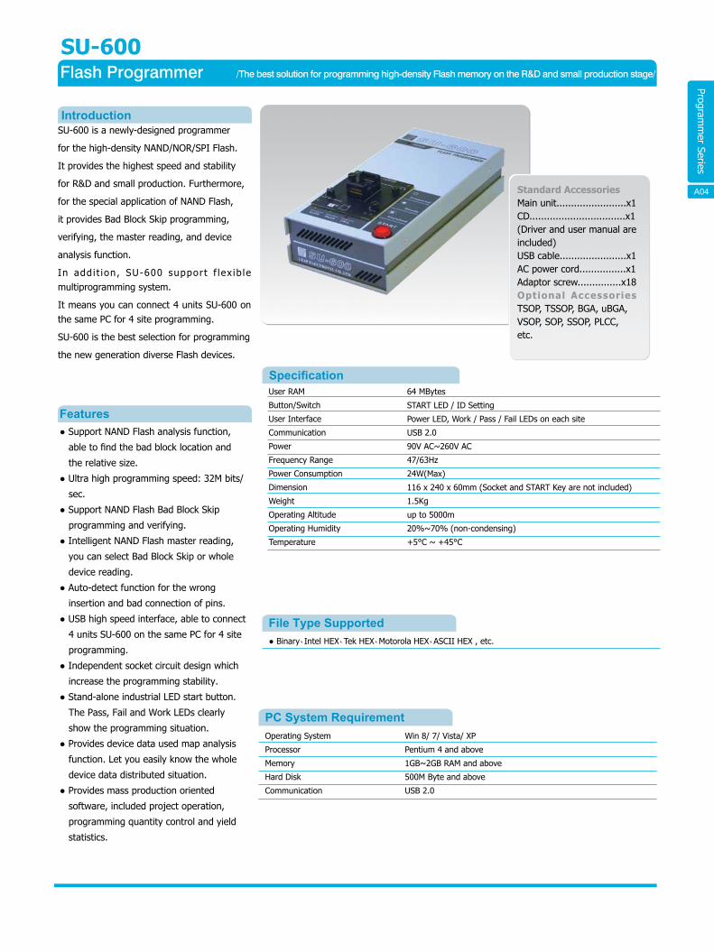
SU-600 is a newly-designed programmer
for the high-density NAND/NOR/SPI Flash.
It provides the highest speed and stability
for R&D and small production. Furthermore,
for the special application of NAND Flash,
it provides Bad Block Skip programming,
verifying, the master reading, and device
analysis function.
In add i t ion, SU-600 support f lex ib le multiprogramming system.
It means you can connect 4 units SU-600 on the same PC for 4 site programming.
SU-600 is the best selection for programming
the new generation diverse Flash devices.
● Support NAND Flash analysis function,
able to find the bad block location and
the relative size.
● Ultra high programming speed: 32M bits/
sec.
● Support NAND Flash Bad Block Skip
programming and verifying.
● Intelligent NAND Flash master reading,
you can select Bad Block Skip or whole
device reading.
● Auto-detect function for the wrong
insertion and bad connection of pins.
● USB high speed interface, able to connect
4 units SU-600 on the same PC for 4 site
programming.
● Independent socket circuit design which
increase the programming stability.
● Stand-alone industrial LED start button.
The Pass, Fail and Work LEDs clearly
show the programming situation.
● Provides device data used map analysis
function. Let you easily know the whole
device data distributed situation.
● Provides mass production oriented
software, included project operation,
programming quantity control and yield
statistics.
Introduction
Features
SpecificationUser RAM
Button/Switch
User Interface
Communication
Power
Frequency Range
Power Consumption
Dimension
Weight
Operating Altitude
Operating Humidity
Temperature
64 MBytes
START LED / ID Setting
Power LED, Work / Pass / Fail LEDs on each site
USB 2.0
90V AC~260V AC
47/63Hz
24W(Max)
116 x 240 x 60mm (Socket and START Key are not included)
1.5Kg
up to 5000m
20%~70% (non-condensing)
+5°C ~ +45°C
PC System Requirement
● Binary˴Intel HEX˴Tek HEX˴Motorola HEX˴ASCII HEX , etc.
Operating System
Processor
Memory
Hard Disk
Communication
Win 8/ 7/ Vista/ XP
Pentium 4 and above
1GB~2GB RAM and above
500M Byte and above
USB 2.0
File Type Supported
SU-600Flash Programmer
A07
/The best solution for programming high-density Flash memory on the R&D and small production stage/
Standard AccessoriesMain unit........................x1CD.................................x1(Driver and user manual areincluded)USB cable.......................x1AC power cord................x1Adaptor screw...............x18 Optional AccessoriesTSOP, TSSOP, BGA, uBGA,VSOP, SOP, SSOP, PLCC,etc.
A04
Programm
er Series
SU-6000Flash Gang 4 Programmer
SU-6000 i s a new l y -de s i gned gang programmer for high-density NAND/NOR Flash memory. It provides the highest speed and stability. Furthermore, for the special application of NAND Flash, it provides Bad Block Skip programming, verifying, master reading and device analysis functions. In addition, the innovative adapter design which lets users change adaptors quickly and save the cost of consumptive materials for mass production.
The transmission rate of SU-6000 is up to 480M bytes/minute and SU-6000 is able to support 4 sites NAND Flash Bad Block Skip programming, verifying and master reading at the same time. It is able to simplify the preparation and increase the work efficiency when mass production. With the outstanding characteristics, SU-6000 is undoubtedly suitable for engineers to overcome the next generation IC programming issue.
● Support NAND Flash Bad Block Skip
programming & verifying on 4 sites
simultaneously.
● Ultra high NAND Flash programming
speed: 32M bits/sec.
● Intelligent NAND FLASH master reading:
Bad Block Skip or whole device reading.
● Auto-detect function: Wrong insertion of
device, bad connection of pins, etc.
● Innovative adapter design: Support
different packages by changing adaptor.
● Independent socket circuit: Increase the
security and stability.
● High speed data transmission: 480M
Bytes/minute.
● Stand-alone industrial LED start button:
Pass, Fail, Work LEDs on each site.
● Operating software for mass production:
Working by project, control programming
quantity, yield rate statistics, etc.
● User-friendly: Flexible for adjusting the
operation angle, able to lay the unit
horizontally or obliquely.
● Built in auto-switching power: Support
100V~240V AC input.
Standard AccessoriesMain unit........................x1CD.................................x1 (Driver and user manual are included)USB cable.......................x1AC power cord................x1Adaptor screw...............x18Optional AccessoriesTSOP, TSSOP, BGA, uBGA, VSOP, SOP, SSOP, PLCC, etc.
Introduction
Features
SpecificationUser RAM
Button/Switch
User Interface
Communication
Power
Frequency Range
Power Consumption
Dimension
Weight
Operating Altitude
Operating Humidity
Temperature
64 MBytes
START LED / ID Setting
Power LED, Work / Pass / Fail LEDs on each site
USB 2.0 High Speed
100V AC~240V AC
50/60Hz
75W(Max)
315 x 240 x 80mm (Socket and START Key are not included)
3.5Kg
up to 5000m
20%~70% (non-condensing)
+5℃ ~ +45℃
● Binary、Intel HEX、Tek HEX、Motorola HEX、ASCII HEX , etc.
PC System RequirementOperating System
Processor
Memory
Hard Disk
Communication
Win 10 / 8 / 7 / Vista / XP ( 32bits & 64bits )
Pentium 4 and above
1GB~2GB RAM and above
500M Byte and above
USB 2.0
File Type Supported
/The best solution for programming high-density Flash memory/
A05A06
Programm
er Series
LEAPER-56Pocket Universal Programmer
Specification
PC System Requirements
Supported Devices
Operating system
Processor
Memory
Hard disk
Communication
USB powere
Win 8 / 7 / Vista / XP ( 32bits & 64bits )
Pentium 4 above
1GB RAM above
500 MB above / buffer: 1GB above
USB 2.0 high speed
Connect the cable with 2 USB port (600mA above)
Device power signal
Power consumption
Pin drivers
DUT socket
Dimension
Weight
Log ic signal level:
IOL, IOH current:
Logic signal frequency:
Signal skew:
Clock frequency :
VDD, VIO level:
IDD, IIO frequency:
VPP, VHH level:
IPP, IHH frequency:
4W
48 Pin Uuiversal Pin Driver
DIP 48 ZIF
136 x 90 x 20mm
282g
Supported File Formats
Remarks
NOR FLASH,SPI,EPROM,EEPROM,MPU,MCU,CPLD,NV-RAM, etc.
Binary/Machine Code, Intel HEX,TEK HEX, Motorola HEX
1.Must use the USB cable from the standard package, and connect to the USB ports behind
your PC. Besides please also connect it with 2 USB ports, or through the USB Hub (5V/1A).
2.When you need adapters to process the high-speed components, be sure to use good
quality adapters. In order to have the best high-frequency process performance, the socket and DUT
must keep good contact.
1.5V~6.0V,10mV
10mA
75MHz (3-5V)
60MHz (2.5V)
45MHz (1.8V)
25MHz (1.5V)
<±2.5nS (3-5V)
0Hz ~ 75MHz
1.5V~6.5V,10mV
400mA
1.5V~15.5V,20mV
150mA
IntroductionThe LEAPER-56 is a pocket size universalprogrammer. It provides with 75MHzbandwidth and < ±2.5nS signal skew justin smart-phone size. The programmingefficiency is much better than the otherprogrammers on the market in any timeand any condition.By letting your PC or laptop connect withLEAPER-56, it will perform your outstandingability of development and debugging. Youcan easily have professional factory-levelproductivity.
LEAPER-56 is most suitable on the mobile environment.
● Portable mini size. Without socket, only 136mm(L)* 90mm(W)* 20mm(H). You just need to connect with USB cable to
use. No additional power supply.● Provide with PIN 75MHz bandwidth and
< ±2.5nS signal skew. In addition to thehigh processing speed, you can verifywhether the ICs processing frequencymeets the specifications.
● Via USB HUB, you can connect multipleLEAPER-56s to do gang programming. Itmakes development and mass productionproficient.
● Provide with DUT device pin checking andmemory components ID verification.Ensure the best yield rate of processing.
● Provides asynchronous and concurrentoperation for the 8 units LEAPER-56 viaUSB hub which allows chips to beginprogramming immediately upon insertionto the socket. There is a message showon the UI to inform operator to take offthe finished device and inserts a newdevice.
Features
A09
The best way to perform your professional capacity
and working efficiency.
(Zero Inser ion Force)
(Socket is not induded)
/ Smart-phone size and ICT level universal programmer
Standard Accessories
Main unit ...................... x1CD ............................... x1(Included driver anduser's manual) Y-USB cable .................. x1Soft case .......................x1
A06
Programm
er Series
LP-456Universal Gang 4 Programmer
LP-456 is ultra-speedy universal 4x48 pin-drive concurrent production programmer. You
can just use the general type adapters on the market for efficient multiprogramming
solution.
● Four independent universal programming
pin-driver in one unit.
● Provides with DUT 75MHz bandwidth and
< ±2.5nS signal skew. In addition to the
high processing speed, you can verify
whether the devices working frequency
meet their specifications.
● Provides Hands-free Operation. The
asynchronous and concurrent operation
allows a chip to begin programming
immediately upon insertion of chip.
The operator just take off the finished
device and inserts a new device.
● Provides mass-production-oriented
software. There is used a Project file to
control LP-456 to minimize the operator
error. Moreover, it provides programming
history and yield statistic for needs of
production managements.
● Provides insertion test and contact check
before programming.
● General type adapter can be used on
LP-456, save money and convenience.
Standard AccessoriesMain unit........................x1CD................................x1 (Included driver & user's manual)USB cable.......................x1Power Adaptor ...............x1
Optional AccessoriesPLCC, JLCC, SDIP, SOP, VSOP, SSOP, TSOP, TSSOP, QFP, PQFP, TQFP, VQFP, BGA, uBGA, SON, WSON, QFN(MLF)..... adapters
Introduction
Features
Specification
Power Signal
PIN DRIVERS
DUT SORCKET
Dimension
Weight
Logic Signal Level
IOL & IOH Current
Logic Signal Frequency
Signal Skew
Clock
VDD & VIO Level
IDD & IIO Current
VPP & VHH Level
IPP& IHH Current
48 Pin Universal Pin-Driver x4
DIP-48 ZIF(Zero Insertion Force) x 4
372 x 205 x 45mm
2.1kg
1.5V~6.0V,10mV
10mA
75MHz (3-5V)
60MHz (2.5V)
45MHz (1.8V)
25MHz (1.5V)
<±2.5nS (3-5V)
0Hz~75MHz
1.5V~6.5V,10mV
400mA
1.5V~15.5V,20mV
150mA
● Binary, Machine Code, Intel HEX, TEK HEX, Motorola HEX
● NOR FLASH, SPI EPROM, EEPROM, MPU, MCU, CPLD, NV-RAM…etc.
PC System RequirementOS
Processor
Memory
Hard Disk
Communication
Windows 8 / 7 / Vista / XP ( 32bits & 64bits )
Pentium 4 Above
2 GB RAM Above
500MB Above
Buffer 1GB Above
USB 2.0 HIGH SPEED
Supported File Format
Supported Devices
/ Universal Pin-driver of high performance /
A08A07
EPROM Eraser/Adaptor Series
EPROM Eraser/Adaptor Series
EPROM
Eraser/Adaptor &
Converters
LER-121A/123AEPROM Eraser
SpecificationModel
Erase Quantity
Dimension
Weight
Operating Altitude
Operating Humidity
Temperature
PLCC Package SOP Package
SSOP Package SOJ Package
TSOP Package PQFP Package
PSOP Package QFP Package
TQFP Package SDIP Package
DIP Package TSSOP Package
FPGA Package μBGA Package
LER-121A
12 pcs (24 PIN)
240 x 85 x 95mm
1.2Kg
up to 5000m90% (non-condensing)
+5℃ ~ +45℃
LER-123A
64 pcs (24 PIN)
370 x 180 x 100mm
3.1Kg
up to 5000m90% (non-condensing)
+5℃ ~ +45℃
IntroductionCombining well performance and low cost, LEAP produces EPROM ERASER. LER-121A/123A that accommodates 12/64 devices (24-Pin x 0.6), and suits for small developing environment.
● Equipped with electronic starter, extend
the product life.
● The timer can be set from 0 to 60
minutes.
● Powerful UV tube, all ICs are ensured for
maximum UV exposure.
● Protect users from UV exposure by
equipped with automatic UV shut off
switch when opening the device drawer.
● LED on the top panel to indicate the
status of UV tube.
● Provide almost completely erase area.
● Light, rugged metal construction.
● The erase time is approximately 15
minutes.
Features
Adaptor & Converter
Standard AccessoriesMain unit........................x1 User manual...................x1DC power adaptor 9V/500mA (LER-121A).....x1AC power cord (LER-123A).....................................x1
Optional AccessoriesLER-121A:4W UV tube.LER-123A:10W UV tube.
A12A08
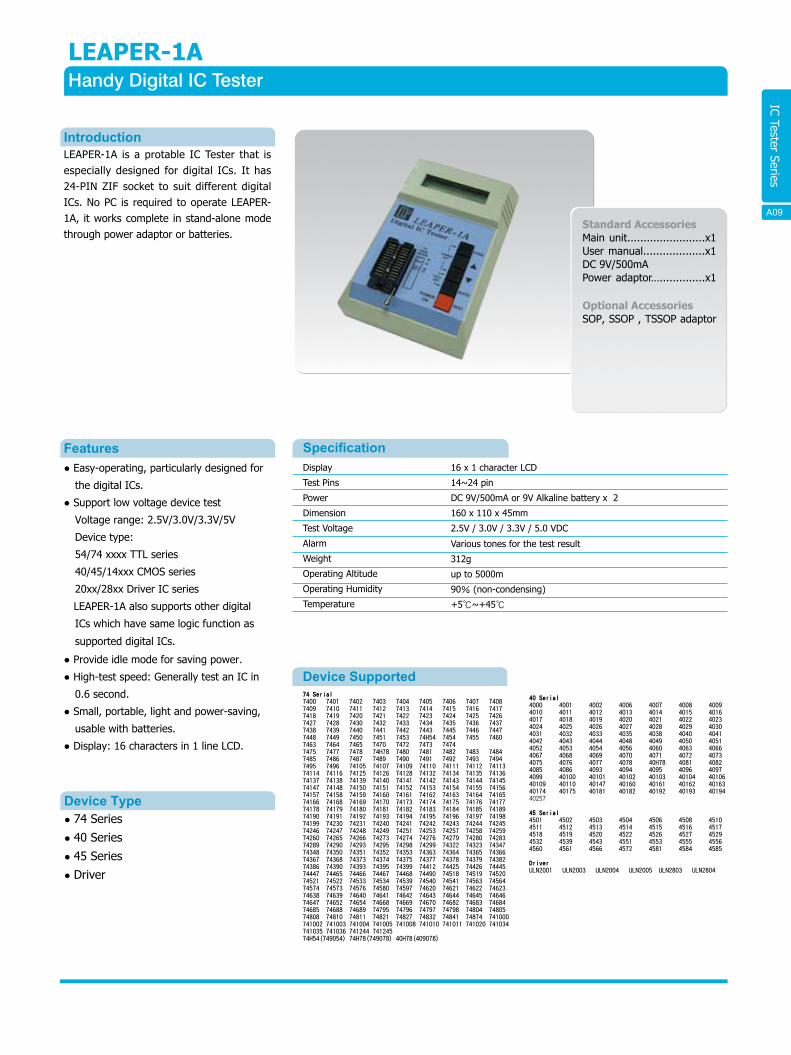
IC Tester Series
LEAPER-1AHandy Digital IC Tester
SpecificationDisplay
Test Pins
Power
Dimension
Test Voltage
Alarm
Weight
Operating Altitude
Operating Humidity
Temperature
16 x 1 character LCD
14~24 pin
DC 9V/500mA or 9V Alkaline battery x 2
160 x 110 x 45mm
2.5V / 3.0V / 3.3V / 5.0 VDC
Various tones for the test result
312g
up to 5000m
90% (non-condensing)
+5℃~+45℃
IntroductionLEAPER-1A is a protable IC Tester that is especially designed for digital ICs. It has 24-PIN ZIF socket to suit different digital ICs. No PC is required to operate LEAPER-1A, it works complete in stand-alone mode through power adaptor or batteries.
Standard AccessoriesMain unit........................x1User manual...................x1DC 9V/500mAPower adaptor…..............x1
Optional AccessoriesSOP, SSOP , TSSOP adaptor
● Easy-operating, particularly designed for
the digital ICs.
● Support low voltage device test
Voltage range: 2.5V/3.0V/3.3V/5V
Device type:
54/74 xxxx TTL series
40/45/14xxx CMOS series
20xx/28xx Driver IC series
LEAPER-1A also supports other digital
ICs which have same logic function as
supported digital ICs.
● Provide idle mode for saving power.
● High-test speed: Generally test an IC in
0.6 second.
● Small, portable, light and power-saving,
usable with batteries.
● Display: 16 characters in 1 line LCD.
Features
Device Type● 74 Series● 40 Series● 45 Series● Driver
Device Supported 74 Serial7400 7401 7402 7403 7404 7405 7406 7407 7408 7409 7410 7411 7412 7413 7414 7415 7416 7417 7418 7419 7420 7421 7422 7423 7424 7425 7426 7427 7428 7430 7432 7433 7434 7435 7436 7437 7438 7439 7440 7441 7442 7443 7445 7446 7447 7448 7449 7450 7451 7453 74H54 7454 7455 7460 7463 7464 7465 7470 7472 7473 74747475 7477 7478 74H78 7480 7481 7482 7483 7484 7485 7486 7487 7489 7490 7491 7492 7493 7494 7495 7496 74105 74107 74109 74110 74111 74112 74113 74114 74116 74125 74126 74128 74132 74134 74135 74136 74137 74138 74139 74140 74141 74142 74143 74144 74145 74147 74148 74150 74151 74152 74153 74154 74155 74156 74157 74158 74159 74160 74161 74162 74163 74164 74165 74166 74168 74169 74170 74173 74174 74175 74176 74177 74178 74179 74180 74181 74182 74183 74184 74185 74189 74190 74191 74192 74193 74194 74195 74196 74197 74198 74199 74230 74231 74240 74241 74242 74243 74244 74245 74246 74247 74248 74249 74251 74253 74257 74258 74259 74260 74265 74266 74273 74274 74276 74279 74280 74283 74289 74290 74293 74295 74298 74299 74322 74323 74347 74348 74350 74351 74352 74353 74363 74364 74365 74366 74367 74368 74373 74374 74375 74377 74378 74379 74382 74386 74390 74393 74395 74399 74412 74425 74426 74445 74447 74465 74466 74467 74468 74490 74518 74519 74520 74521 74522 74533 74534 74539 74540 74541 74563 74564 74574 74573 74576 74580 74597 74620 74621 74622 74623 74638 74639 74640 74641 74642 74643 74644 74645 74646 74647 74652 74654 74668 74669 74670 74682 74683 74684 74685 74688 74689 74795 74796 74797 74798 74804 74805 74808 74810 74811 74821 74827 74832 74841 74874 741000 741002 741003 741004 741005 741008 741010 741011 741020 741034 741035 741036 741244 741245 74H54(749054) 74H78(749078) 40H78(409078)
40 Serial4000 4001 4002 4006 4007 4008 4009 4010 4011 4012 4013 4014 4015 4016 4017 4018 4019 4020 4021 4022 4023 4024 4025 4026 4027 4028 4029 4030 4031 4032 4033 4035 4038 4040 4041 4042 4043 4044 4048 4049 4050 4051 4052 4053 4054 4056 4060 4063 4066 4067 4068 4069 4070 4071 4072 4073 4075 4076 4077 4078 40H78 4081 4082 4085 4086 4093 4094 4095 4096 4097 4099 40100 40101 40102 40103 40104 40106 40109 40110 40147 40160 40161 40162 40163 40174 40175 40181 40182 40192 40193 40194 40257
45 Serial4501 4502 4503 4504 4506 4508 45104511 4512 4513 4514 4515 4516 45174518 4519 4520 4522 4526 4527 45294532 4539 4543 4551 4553 4555 45564560 4561 4566 4572 4581 4584 4585
DriverULN2001 ULN2003 ULN2004 ULN2005 ULN2803 ULN2804
A13 A09
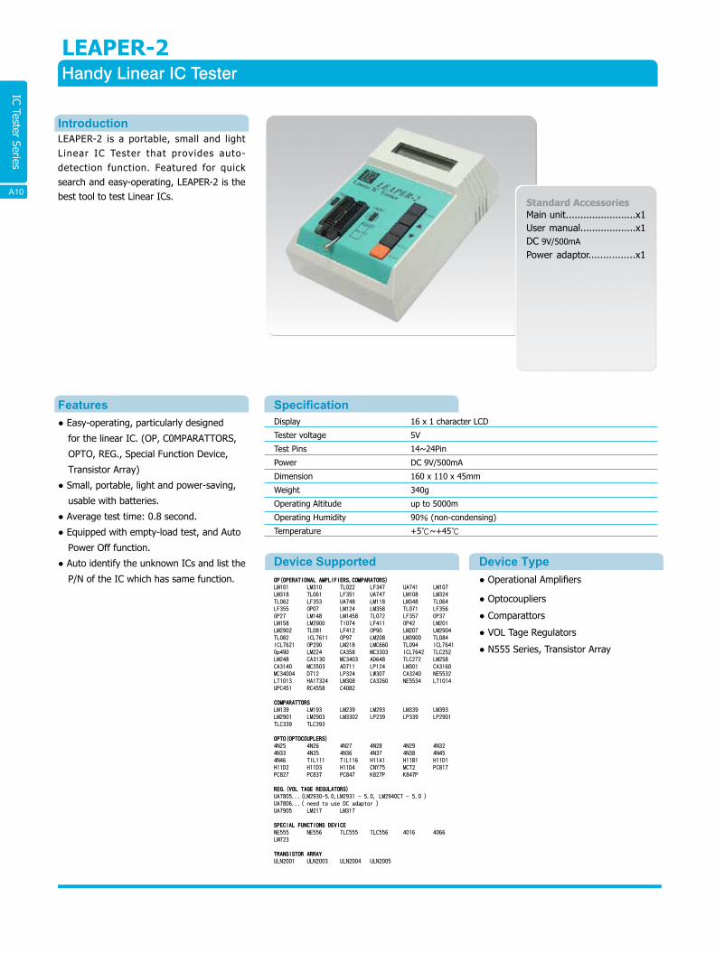
IC Tester Series
LEAPER-2Handy Linear IC Tester
SpecificationDisplay
Tester voltage
Test Pins
Power
Dimension
Weight
Operating Altitude
Operating Humidity
Temperature
16 x 1 character LCD
5V
14~24Pin
DC 9V/500mA
160 x 110 x 45mm
340g
up to 5000m
90% (non-condensing)
+5℃~+45℃
Device SupportedOP(OPERATIONAL AMPLIFIERS,COMPARATORS)LM101 LM310 TL022 LF347 UA741 LM107 LM318 TL061 LF351 UA747 LM108 LM324 TL062 LF353 UA748 LM118 LM348 TL064 LF355 OP07 LM124 LM358 TL071 LF356 OP27 LM148 LM1458 TL072 LF357 OP37 LM158 LM2900 Tl074 LF411 OP42 LM201 LM2902 TL081 LF412 OP90 LM207 LM2904 TL082 ICL7611 OP97 LM208 LM3900 TL084 ICL7621 OP290 LM218 LMC660 TL094 ICL7641 Op490 LM224 CA358 MC3303 ICL7642 TLC252 LM248 CA3130 MC3403 AD648 TLC272 LM258 CA3140 MC3503 AD711 LP124 LM301 CA3160 MC34004 D712 LP324 LW307 CA3240 NE5532 LT1013 HA17324 LM308 CA3260 NE5534 LT1014 UPC451 RC4558 C4082
COMPARATTORSLM139 LM193 LM239 LM293 LM339 LM393 LM2901 LM2903 LM3302 LP239 LP339 LP2901 TLC339 TLC393
OPTO(OPTOCOUPLERS)4N25 4N26 4N27 4N28 4N29 4N32 4N33 4N35 4N36 4N37 4N38 4N45 4N46 TIL111 TIL116 H11A1 H11B1 H11D1 H11D2 H11D3 H11D4 CNY75 MCT2 PC817 PC827 PC837 PC847 K827P K847P
REG.(VOL TAGE REGULATORS)UA7805...(LM2930-5.0,LM2931 - 5.0, LM2940CT - 5.0 )UA7806...( need to use DC adaptor )UA7905 LM217 LM317
SPECIAL FUNCTIONS DEVICENE555 NE556 TLC555 TLC556 4016 4066 LM723
TRANSISTOR ARRAYULN2001 ULN2003 ULN2004 ULN2005
Device Type● Operational Amplifiers
● Optocoupliers
● Comparattors
● VOL Tage Regulators
● N555 Series, Transistor Array
IntroductionLEAPER-2 is a portable, small and light Linear IC Tester that provides auto-detection function. Featured for quick search and easy-operating, LEAPER-2 is the best tool to test Linear ICs.
● Easy-operating, particularly designed
for the linear IC. (OP, C0MPARATTORS,
OPTO, REG., Special Function Device,
Transistor Array)
● Small, portable, light and power-saving,
usable with batteries.
● Average test time: 0.8 second.
● Equipped with empty-load test, and Auto
Power Off function.
● Auto identify the unknown ICs and list the
P/N of the IC which has same function.
Features
Standard AccessoriesMain unit........................x1User manual...................x1DC 9V/500mA
Power adaptor................x1
A14A10
IC Tester Series
Features
Device Supported 74 Serial7400 7401 7402 7403 7404 7405 7406 7407 7408 7409 7410 7411 7412 7413 7414 7415 7416 7417 7418 7419 7420 7421 7422 7423 7424 7425 7426 7427 7428 7430 7432 7433 7434 7435 7436 7437 7438 7439 7440 7441 7442 7443 7445 7446 7447 7448 7449 7450 7451 7453 74H54 7454 7455 7460 7463 7464 7465 7470 7472 7473 74747475 7477 7478 74H78 7480 7481 7482 7483 7484 7485 7486 7487 7489 7490 7491 7492 7493 7494 7495 7496 74105 74107 74109 74110 74111 74112 74113 74114 74116 74125 74126 74128 74132 74134 74135 74136 74137 74138 74139 74140 74141 74142 74143 74144 74145 74147 74148 74150 74151 74152 74153 74154 74155 74156 74157 74158 74159 74160 74161 74162 74163 74164 74165 74166 74168 74169 74170 74173 74174 74175 74176 74177 74178 74179 74180 74181 74182 74183 74184 74185 74189 74190 74191 74192 74193 74194 74195 74196 74197 74198 74199 74230 74231 74240 74241 74242 74243 74244 74245 74246 74247 74248 74249 74251 74253 74257 74258 74259 74260 74265 74266 74273 74274 74276 74279 74280 74283 74289 74290 74293 74295 74298 74299 74322 74323 74347 74348 74350 74351 74352 74353 74363 74364 74365 74366 74367 74368 74373 74374 74375 74377 74378 74379 74382 74386 74390 74393 74395 74399 74412 74425 74426 74445 74447 74465 74466 74467 74468 74490 74518 74519 74520 74521 74522 74533 74534 74539 74540 74541 74563 74564 74574 74573 74576 74580 74597 74620 74621 74622 74623 74638 74639 74640 74641 74642 74643 74644 74645 74646 74647 74652 74654 74668 74669 74670 74682 74683 74684 74685 74688 74689 74795 74796 74797 74798 74804 74805 74808 74810 74811 74821 74827 74832 74841 74874 741000 741002 741003 741004 741005 741008 741010 741011 741020 741034 741035 741036 741244 741245 74H54(749054) 74H78(749078) 40H78(409078)
40 Serial4000 4001 4002 4006 4007 4008 4009 4010 4011 4012 4013 4014 4015 4016 4017 4018 4019 4020 4021 4022 4023 4024 4025 4026 4027 4028 4029 4030 4031 4032 4033 4035 4038 4040 4041 4042 4043 4044 4048 4049 4050 4051 4052 4053 4054 4056 4060 4063 4066 4067 4068 4069 4070 4071 4072 4073 4075 4076 4077 4078 40H78 4081 4082 4085 4086 4093 4094 4095 4096 4097 4099 40100 40101 40102 40103 40104 40106 40109 40110 40147 40160 40161 40162 40163 40174 40175 40181 40182 40192 40193 40194 40257
45 Serial4501 4502 4503 4504 4506 4508 45104511 4512 4513 4514 4515 4516 45174518 4519 4520 4522 4526 4527 45294532 4539 4543 4551 4553 4555 45564560 4561 4566 4572 4581 4584 4585
Driver ULN2001 ULN2003 ULN2004 ULN2005 ULN2803 ULN2804
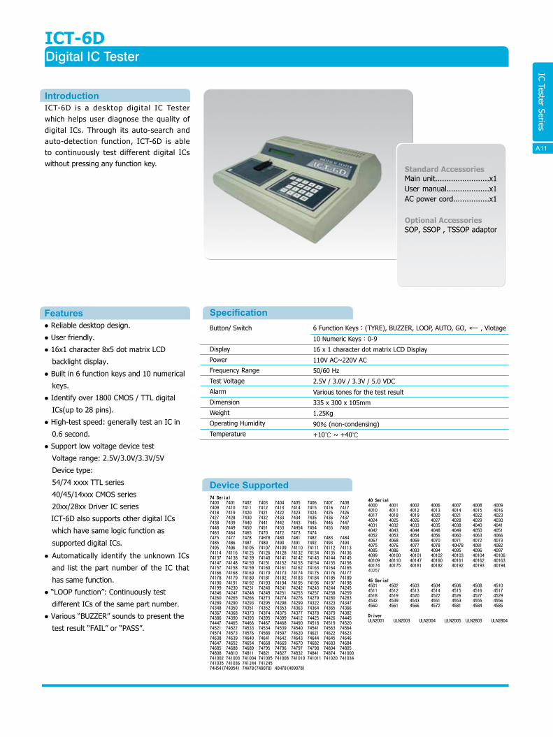
ICT-6DDigital IC Tester
Button/ Switch
Display
Power
Frequency Range
Test Voltage
Alarm
Dimension
Weight
Operating Humidity
Temperature
6 Function Keys:(TYRE), BUZZER, LOOP, AUTO, GO, , Vlotage
10 Numeric Keys:0-9
16 x 1 character dot matrix LCD Display
110V AC~220V AC
50/60 Hz
2.5V / 3.0V / 3.3V / 5.0 VDC
Various tones for the test result
335 x 300 x 105mm
1.25Kg
90% (non-condensing)
+10℃ ~ +40℃
IntroductionICT-6D is a desktop digital IC Tester which helps user diagnose the quality of digital ICs. Through its auto-search and auto-detection function, ICT-6D is able to continuously test different digital ICs without pressing any function key.
● Reliable desktop design.
● User friendly.
● 16x1 character 8x5 dot matrix LCD
backlight display.
● Built in 6 function keys and 10 numerical
keys.
● Identify over 1800 CMOS / TTL digital
ICs(up to 28 pins).
● High-test speed: generally test an IC in
0.6 second.
● Support low voltage device test
Voltage range: 2.5V/3.0V/3.3V/5V
Device type:
54/74 xxxx TTL series
40/45/14xxx CMOS series
20xx/28xx Driver IC series
ICT-6D also supports other digital ICs
which have same logic function as
supported digital ICs.
● Automatically identify the unknown ICs
and list the part number of the IC that
has same function.
● “LOOP function”: Continuously test
different ICs of the same part number.
● Various “BUZZER” sounds to present the
test result “FAIL” or “PASS”.
Standard AccessoriesMain unit........................x1User manual...................x1AC power cord................x1
Optional AccessoriesSOP, SSOP , TSSOP adaptor
A10
Specification
A15 A11
IC Tester Series
Device SupportedOP(OPERATIONAL AMPLIFIERS,COMPARATORS)LM101 LM107 LM108 LM113 LM124 LM148 LM158 LM201 LM207 LM208 LM218 LM224LM248 LM258 LM307 LM308 LM310 LM318 LM324 LM348 LM358 LM1458 LM2900 LM2902LM2904 LM3900 LMC660 CA358 CA3130 CA3140 CA3160 CA3240 CA3260 CA3401 TL022 TL061TL062 TL064 TL071 TL072 TL074 TL081 TL082 TL084 TL094 MC3303 MC3403 MC3503MC34004 NE5532 NE5534 LF347 LF351 LF353 LF355 LF356 LF357 LF411 LF412 ICL7611ICL7621 ICL7641 ICL7642 AD648 AD711 AD712 LT1013 LT1014 RC4558 uA741 uA747 uA748OP07 OP27 OP37 OP42 OP90 OP97 OP290 OP490 TLC252 TLC272 LP124 LP324HA17324 uPC451 C4082
COMPARATTORSLM139 LM193 LM239 LM293 LM339 LM393 LM2901 LM2903 LM3302 LP239 LP339 LP2901TLC339 TLC393
OPTO(OPTOCOUPLERS)4N25 4N26 4N27 4N28 4N29 4N32 4N33 4N35 4N36 4N37 4N38 4N454N46 CNY75 H11A1 H11B1 H11D1 H11D2 H11D3 H11D4 K827P K847P MCT2 PC817PC827 PC837 PC847 TIL111 TIL116
VOLTAGE REGULATORSuA7805..(LM2930-5.0,LM2931-5.0,LM2940CT-5.0)uA7806 uA7808 uA7809 uA7810 uA7812 uA7815 uA7818 uA7824 uA7905 uA7908 uA7912 uA7915uA7924 LM217 LM317 Zener
REG.(VOL TAGE REGULATORS)NE555 NE556 TLC555 TLC556 4016 4066 LM723
TRANSISTOR ARRAYULN2001 ULN2003 ULN2004 ULN2005
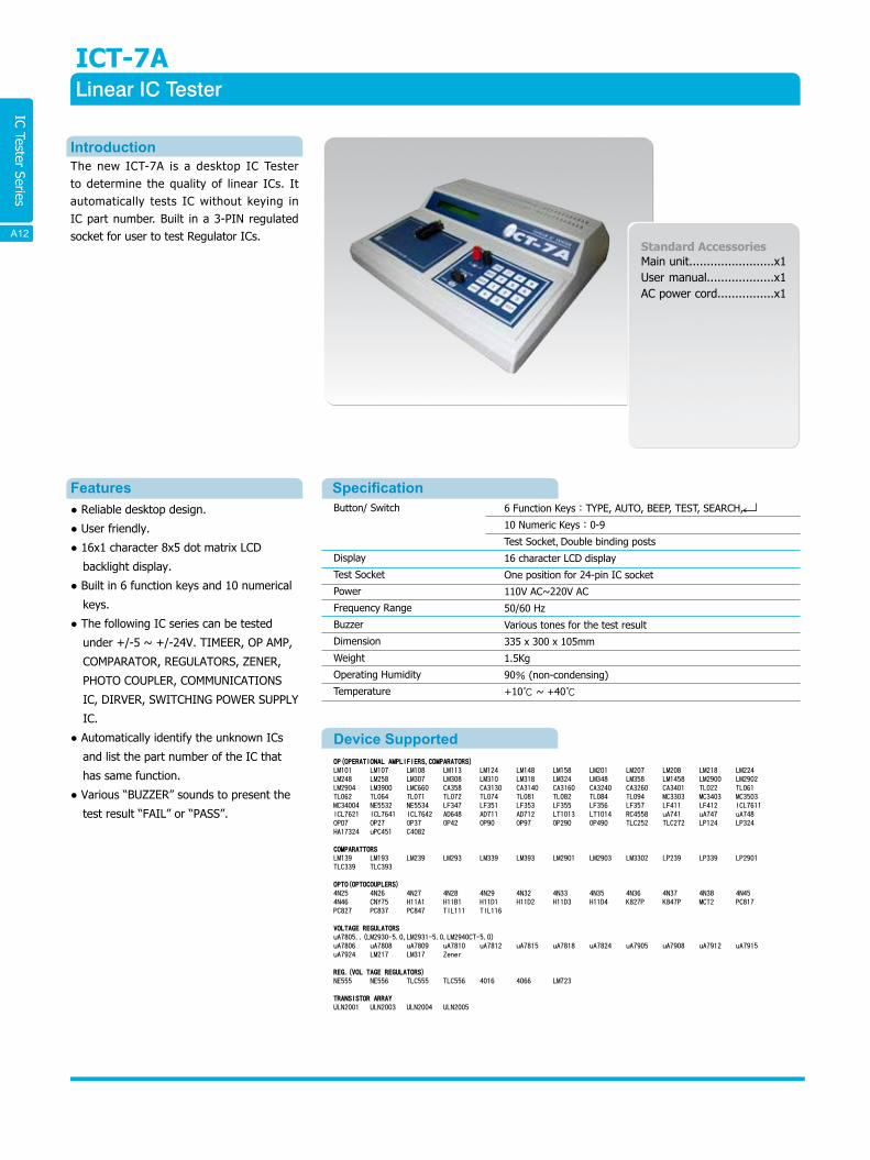
ICT-7ALinear IC Tester
SpecificationButton/ Switch
Display
Test Socket
Power
Frequency Range
Buzzer
Dimension
Weight
Operating Humidity
Temperature
6 Function Keys:TYPE, AUTO, BEEP, TEST, SEARCH,
10 Numeric Keys:0-9
Test Socket,Double binding posts
16 character LCD display
One position for 24-pin IC socket
110V AC~220V AC
50/60 Hz
Various tones for the test result
335 x 300 x 105mm
1.5Kg
90% (non-condensing)
+10℃ ~ +40℃
IntroductionThe new ICT-7A is a desktop IC Tester to determine the quality of linear ICs. It automatically tests IC without keying in IC part number. Built in a 3-PIN regulated socket for user to test Regulator ICs.
● Reliable desktop design.
● User friendly.
● 16x1 character 8x5 dot matrix LCD
backlight display.
● Built in 6 function keys and 10 numerical
keys.
● The following IC series can be tested
under +/-5 ~ +/-24V. TIMEER, OP AMP,
COMPARATOR, REGULATORS, ZENER,
PHOTO COUPLER, COMMUNICATIONS
IC, DIRVER, SWITCHING POWER SUPPLY
IC.
● Automatically identify the unknown ICs
and list the part number of the IC that
has same function.
● Various “BUZZER” sounds to present the
test result “FAIL” or “PASS”.
Features
Standard AccessoriesMain unit........................x1User manual...................x1AC power cord................x1
A16A12
Emulator Series
Specification
LS-2 Plus Wireline Simulator
Cable FeaturesCable Type
Individual Line Distance
DC Characteristics
Frequency
26 AWG
23,500ft (Max) / 250ft (Min)
100mA(Max), 300V DC
Max 2.5 MHz
Connection FeaturesFront control board:8 way RJ-45 connection.......................x2
Back control board:8 way RJ-45 connection........................x2
Ground connection..............................................................x2
Terminal.............................................................................x1
IntroductionADSL2 PLUS has been more populary app l i ed because o f t he i n c reas ing application of High-Bandwidth Multi-Media which contains video, data and voice. ADSL2 PLUS is much advanced and popular than traditional copper network , hence it is necessary to have a simulator that can precisely simulate transmission lines. LS-2 Plus is the best solution for the wireline and noise test.
● Simulate 26 AWG up to 23.5kft with
0.25kft minimum resolution.
● Support ADLS2+, ADSL2, XDSL HDSL, T1
and E1 Modems/Transceivers.
● 7-segment LED display to indicate
simulating cable length.
● Able to work without PC or the control
software. Quickly simulate and test
different lengths of cable through
switching from different 4 memory keys.
● Utilize an addition and deduction button
to progressively divert the simulating
cable lengths, for the convenience of
under testing the circuit characteristics
from the changes and turning points.
● Through a computer user can remotely
control via RS-232 interface providing the
user with speedy simulation of different
cable line lengths.
● Form attached containing program
language templates, providing users to
develop control programs by themselves.
● Use 19” standard instrument case suitable
for users to construct their own testing
system.
Features
Standard AccessoriesMain unit........................x1AC power adaptor............x1RS-232 cable..................x1CD.................................x1 (Driver and user manual are included)
Button/ Switch
Display
Communication
Power
Dimension
Weight
Operating Altitude
Operating Humidity
Temperature
Power Switch ..................x1
Line Length Button ..........x2
Fast Memory Key .............x4
4 digit red 7 segment LED display
Remote control indicate light input
RS-232
110V AC / 220V AC
132 x 430 x 386mm
4.8Kg
up to 5000m90% (non-condensing)
+5℃ ~ +45℃
A17 A13
Emulator Series
A20
WICE-80528052 In-Circuit Emulator
SpecificationCommunication
Power
Dimension
Weight
Operating Altitude
Operating Humidity
Temperature
Printer port
100V AC~240V AC
140 x 110 x 46mm
380g
up to 5000m
90% (non-condensing)
+5℃ ~ +45℃
Supported Deviceintel
ATMEL
PHILIP
SIEMENS
WINDBOND
8031 8032 80C31 80C32 8xC51 8xC52 8xC54 8xC58 8xL52 8xL54
89C51 89C52 89C55 89LV51 89LV52
8031 8051 80C31 80C32 8xC51 8xC52 8xCL31 8xCL51 8xC851
8031 8032 8051 8052 C501 C502
W78C31B W78C32B
Execution Function● Full Speed Running Stop, Step Into, Slow Run Into, Slow Run Over, Step Over & Run
Until.
File Type Supported● Binary / Machine code、intel HEX.
IntroductionThe WICE-8052, In-circuit Emulator for 8052 microcontrollers, is a well-developed product by LEAP ELECTRONIC. The WICE-8052 is designed specifically for todays engineers who need an excellent tool for their projects. It combines real-time emulation up to 40 MHz with multi-windows, point-and-click, menu-driven function and on-line help. WICE-8052 assists users' designs quickly and efficiently.
● Support 64K hardware fu l l range
execution breakpoints, al low for a
pause at any point to avoid any other
unnecessary procedures.
● Real time to record 32K frame*16 bit
address.
● Real time record start and end address,
observed program and distribution map.
● S imu la te m i c rocon t ro l l e r f am i l y :
80(C)31/32, 80(C)51/52, 87(C)51/52,
89(C)51/52.
● Provide 128K Byte simulation memory
(program 64K, data 64K).
● Provide synchronous output signal with
RESET for ICE.
● Speedy download v ia pr inter port
interface.
● Able to disassemble on-line.
● Functional register with categorical
displays: directly perform bit-setting on
each special functional register. The flag
values will assist auxiliary function details.
● Special design for detecting wrong
insertions, also protects the system from
recieving over 5V input.
● Able to switch internal and external
frequencies.
● Speed of emulation up to 40MHz clock.
● Support 3.3V~5V devices.
Standard AccessoriesMain unit.............................x1
CD(Driver and user manual are
included).............................x1
User manual........................x1
26-pin cable.........................x1
40-pin module+flat cable......x1
40-pin cable.........................x1
2-pin signal line hook............x1
40-pin IC socket...................x1
DC 5V/1A power adaptor.......x1
EXT crystal adaptor...............x1
Optional AccessoriesPLCC44 adaptor....................x1
PC System RequirementOperating System
Processor
Memory
Hard Disk
Windows 98/ME/2000/XP
Pentium III and above
128MB RAM and above
30MB and above
Features
A14
Emulator Series
WICE-52MCS-51 On-Board-Debug
SpecificationCommunication
Power
Dimension
Weight
USB
USB
70 x 23 x 15mm
22g
Introduction8051 is the most popular single chip on the microcontroller series. It is the best option to learn the basic experiment or circuit design for the department o f Sc ience and Eng ineer ing . When you conduct the MCS-51 experiments or debug i ts program, the WICE-52 can provide you the best assistance.
The WICE-52 adopts OCD(On-Chip-Debug) technology from company Megawin. It is compatible with Keil ’s 8051 IDE debug simulation interface and supports “Single Step”, “Full Speed”, “Pause”, and “Reset” functions of on-chip debugging.
• Mini size, only 70mm(L) x 23mm(W)
x15mm(H). You can insert it into the
8051 socket of the PCB and connect
with the PC via USB cable for starting
using.
• Support standard MCS-51 series IC
which ROM is under 64K Bytes debug
&emulate function.
• For 1T MCU commands can be
conducted within 1-3 clock and up to
24MIPS. If you want to emulate 4T or
12T 8051 IC by WICE-52, must notice
the difference of clock and the delay
setting.
• Power Monitor is embedded. When VDD
is under-voltage, it will interrupt or
reset.
• Directly using Keil 8051 IDE software
interface. The debug function is applied
to Keil IDE dScope-Debugger. It is
compatible with Keil’s μVision2 or
μVision3. (Note: Keil 8051 IDE software
is not included in the product.)
• Powerful debug function: “Single Step”,
“full Speed”, “Pause”, and “Reset” etc.
• Programmable interrupts, user can
insert 4 interrupts in one time.
• Keil 8051 IDE, contains register/
_disassembler/ watch/ memory etc.
• Going with the Leap UP-2,MCS-51/AVR/
PIC MCU Experimental Board, is best
trainer for MCU.
Standard AccessoriesMain unit…………………………x1
USB Cable……………………….x4
CD-ROM
(User's manual included)�…x4
Supported Device1. The core chip of the WICE-52 is the high performance 1T framework. When using
early 4T/ 6T/ 12T 8051 devices, must pay attention to the setting of the clock and
delay.
2. Due to the 1T framework, the quartz crystal only needs 24MHz(MAX) can achieve
24MIPS performance. It's much higher other 8051 devices of 4T framework which
work at 40MHz, 10MIPS performance. The quartz crystal is embedded in the WICE-52
and common clock is 12MHz/ 22MHz.
Hardware Specification(same as Megawin MPC82G516)
Features
The Best Tool for Emulating/ Debugging/ Learning 8051
μP-2
WICE-52
Function Internal RC oscillator
Quartz clockRAMROM
I/O portInterrupts
EXINTTimer/ Counter
WDTUARTSPIADCPCA
Package
Description Do not need external oscillatorBuilt-in quartz clock selectionInternal + Extended SRAMInternal / External (byte)
2 way I/O pinsPeripherals workExternal Interrupt
16-bit counterWatchdog timer
Asynchronous serial portSerial peripheral interface10-bit analog to digitalPWM, catcher included
IC package
Specification 6MHz (1T)
12/22MHz(1T)256+1K(XRAM)
64K/64K32、36 or 4014 interrupts
43 sets
Support2 setsYes
8 channels6 setsDIP-40
A15A21
Learning Kits Series
B15
μP-2MCS-51 / AVR / PIC MCU Experimental Board
IntroductionThe uP-2 is included MCS-51, AVRand PIC which are the top 3 popularMCUs on the market. The platform isflexible design. Each part of theexperiments has their own circuitblock. You can combine the experimentalexample or designated topiccircuit for your own subject. The uP-2is the best platform for learning MCU.
• Applied subjects are included
MCS-5X/AVR/PIC16F8XX.
• Available 20 or 40 pin MUC.
• Compatible with many brands of
emulators.
• System is designed on stand-along
CPU, interface separately.
• Provide 26 circuit units.
• All of the circuits are able to combined
with cable wires by users.
• No need to Solder, saving time.
• 385 holes on the board which provide
users for extended application or
subjective experiments.
• The Power is provided two kinds of
input, 9V adaptor or DC 9V.
• 20 & 40 pin MCS-51/AVR IC socket• 20 & 40 pin PIC16F8XX IC socket• USB• RS-232• Printer port• EPROM/FLASH socket for programextension, up to 512K x 8bits
• SRAM socket for program extension, up to512K x 8bits
• IO decoder• Red/yellow/green LED• 6 digits 7 segment display• Stand-along push button x 4• DIP switches• 16x16 two colors dot matrix LED• System power supply• A/D ADC0804 IC• D/A AD7528 IC• LCD socket extension.• OP LM324 IC• Relay x 4• Step Motor driver ULN2003
Standard AccessoriesMain Board.....................x18 Pin Cable.....................x44 Pin Cable.....................x42 Pin Cable.....................x8USB Cable......................x1CD (Included user’s manual,Boot codes, examples)...x1AC110V/DC9V/500mAPower Adaptor................x1W78E052DDG IC............x1
Features
Circuit Unit
Experimental Contents• LED• Push button• Single and dual Traffic light control• Neon lamp• Extended program memory• Extended data memory• Extended EEPROM recode data• 16x16 double color dot matrix display,Character/graph
• 6 digits dynamic 7 segment displayLCD circuit (LCD is option)
• Step motor driver circuit (needconnect toexternal motor)
• Relay control 4x4 matrix keypad scancircuit
• Press button circuit• Touch switch read and set• Timer• Password key• Electronic piano
• Counter• A/D and D/A conversion• 8255 I/O extension• Multi I/O decode• Serial Peripheral Interface• Printer interface• USB interface• USB transfer to RS-232• OPTO input & output
The best platform for learning MCU
SpecificationCommunication
Power
Dimension
Weight
Printer / RS-232 / USB Port
9V DC Adaptor / 9V DC Extend Power Pinin
316 x 222 x 210mm
700g
B16 B01
• 82C55 IO extension• Buzzer output• EEPROM 93C46 & 24C02• Matrix keypad circuit x 16(4x4)• Photo• 385 hole universal board
Learning Kits Series
Optional Accessories
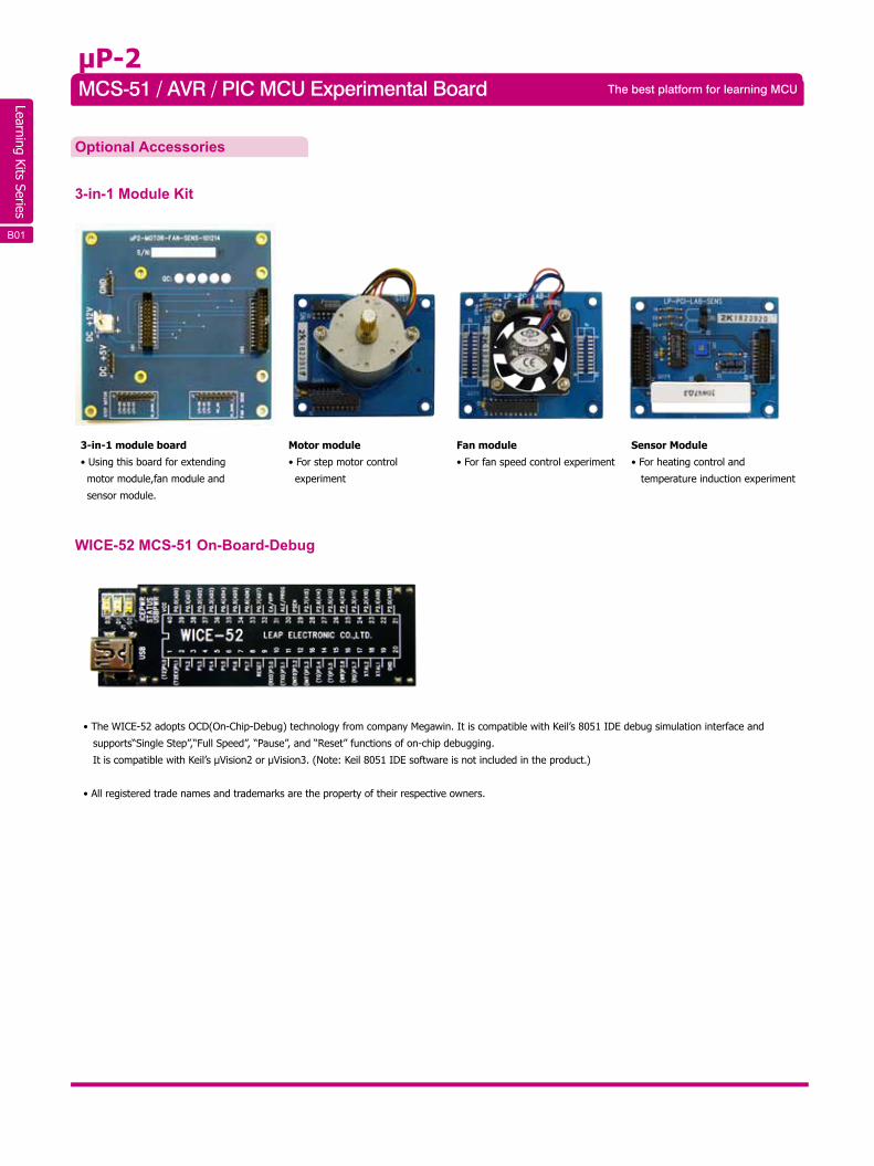
3-in-1 Module Kit
WICE-52 MCS-51 On-Board-Debug
• The WICE-52 adopts OCD(On-Chip-Debug) technology from company Megawin. It is compatible with Keil’s 8051 IDE debug simulation interface and
supports“Single Step”,“Full Speed”, “Pause”, and “Reset” functions of on-chip debugging.
It is compatible with Keil’s μVision2 or μVision3. (Note: Keil 8051 IDE software is not included in the product.)
• All registered trade names and trademarks are the property of their respective owners.
3-in-1 module board
• Using this board for extending
motor module,fan module and
sensor module.
Motor module
• For step motor control
experiment
Fan module
• For fan speed control experiment
Sensor Module
• For heating control and
temperature induction experiment
μP-2MCS-51 / AVR / PIC MCU Experimental Board The best platform for learning MCU
B17B01
Learning Kits Series
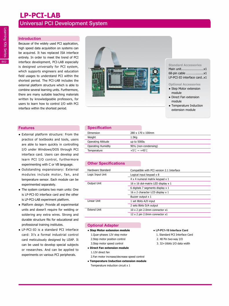
LP-PCI-LAB Universal PCI Development System
SpecificationDimension
Weight
Operating Altitude
Operating Humidity
Temperature
280 x 170 x 100mm
1.5Kg
up to 5000m
90% (non-condensing)
+5℃ ~ +45℃
Hardware Standard
Logic Input Unit
Output Unit
Linear Unit
Extend Unit
Compatible with PCI version 2.1 Interface
Logical input keypad x 8
4 x 4 numeral matrix keypad x 1
16 x 16 dot-matrix LED display x 1
6 digitals 7 segments display x 1
16 x 2 character LCD display x 1
Buzzer output x 1
1 set 8bits A/D input
2 sets 8bits D/A output
10 x 2 pin 2.0mm connector x1
12 x 2 pin 2.0mm connector x1
Other Specifications
IntroductionBecause of the widely used PCI application, high speed data acquisition on systems can be acquired. It has replaced ISA interface entirely. In order to meet the trend of PCI interface development, PCI-LAB especially is designed universally for PCI system, which supports engineers and education field usages to understand PCI within the shortest period. The PCI-LAB includes the external platform structure which is able to combine several learning units. Furthermore, there are many suitable teaching materials written by knowledgeable professors, for users to learn how to control I/O with PCI interface within the shortest period.
● External platform structure: From the
practice of textbooks and tools, users
are able to learn quickly in controlling
I/O under Windows/DOS through PCI
interface card. Users can develop and
learn PCI I/O control, furthermore
experimenting with C or VB language.
● Outstanding expansionary: External
modu les inc lude motor , fan , and
temperature sensor. Each module can be
experimented separately.
● The system contains two main units: One
is LP-PCI-IO interface card and the other
is LP-PCI-LAB experiment platform.
● Platform design: Provide all experimental
units and doesn’t require for welding or
soldering any extra wires. Strong and
durable structure fits for educational and
professional training institutes.
● LP-PCI-IO is a standard PCI interface
card: It’s a formal industrial control
card meticulously designed by LEAP. It
can be used to develop special subjects
or researches. And can be applied to
experiments on various PCI peripherals.
Standard AccessoriesMain unit........................x168-pin cable …………........x1LP-PCI-IO interface card..x1
Optional Accessories● Step Motor extension module ● Direct Fan extension
module● Temperature Induction
extension module
Features
Optional Adapter● Step Motor extension module
1.Quar-phases 12V step motor
2.Step motor position control
3.Step motor speed control
● Direct Fan extension module
1.12V direct fan
2.Fan motor increase/decrease speed control
● Temperature Induction extension module
Temperature induction circuit x 1
● LP-PC1-10 Interface Card1. Standard PCI Interface Card
2. 48 Pin two-way I/O
3. 32+16bits I/O data width
B02 B 07
Learning Kits Series
• Leaptronix LA-2025 / LA-2050 / PLA-1016 / PLA-2532
Specifications
Recommended Bundling Instruments
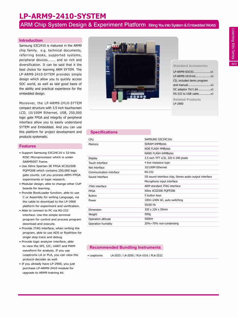
LP-ARM9-2410-SYSTEMARM Chip System Design & Experiment Platform /Bring You into System & Embedded World/
CPU
Memory
Display
Touch interface
Net interface
Communication interface
Sound interface
JTAG interface
FPGA
Button
Power
Dimension
Weight
Operation altitude
Operation humidity
SAMSUNG S3C24C10x
SDRAM 64MBytes
NOR FLASH 4MBytes
NAND FLASH 64MBytes
3.5 inch TFT LCD, 320 X 240 pixels
4 line resisance type
10/100M Ethernet
RS-232
IIS sound interface chip, Stereo audio output interface
Microphone input interface
ARM standard JTAG interface
Xilinx XCS250E PQFP208
5 button keys
100V~240V AC, auto switching
50/60 Hz
320 x 226 x 30mm
500g
5000m
20%~70% non-condensing
IntroductionSamsung S3C2410 is maturest in the ARM9 chip family, e.g. technical documents, referr ing books, supported systems, peripheral devices....... and so rich and diversification. It can be said that it the best choice for learning ARM SYTEM. The LP-ARM9-2410-SYTEM provides simple design which allow you to quickly access SOC world, as well as laid good basis of the ability and practical experience for the embedded design.
Moreover, the LP-ARM9-2410-SYTEM compact structure with 3.5 inch touchscreen LCD, 10/100M Ethernet, USB, 250,000 logic gate FPGA and integrity of peripheral interface allow you to easily understand SYTEM and Embedded. And you can use this platform for project development and products systematic.
• Support Samsung S3C24C10 x 32-bits
RISC Microprocessor which is under
SARM920T frame.
• Use Xilinx Spartan-3E FPGA XC3S250E
PQFP208 which contains 250,000 logic
gate counts. Let you process ARM+FPGA
experiments or topic research.
• Modular design, able to change other CUP
boards for learning.
• Provide BootLoader function, able to use
C or Assembly for writing Language, via
the cable to download to the LP-2900
platform for experiment and verification.
• Able to connect to PC via RS-232
interface. Use the simple terminal
program for control and process program
download and execute.
• Provide JTAG interface, when writing the
program, able to use ADS or RealView for
single step trace and debug.
• Provide logic analyzer interface, able
to view the SPI, I2C, UART and PWM
waveform for analysis. If you use
Leaptronix LA or PLA, you can view the
protocol decoder as well.
• If you already have LP-2900, you just
purchase LP-ARM9-2410 module for
upgrade to ARM9 training kit.
Features
Standard Accessories
LP-ARM9-SOCIO....................x1
LP-ARM9-2410-kit..................x1
CD, included demo program
and manual...........................x1
DC adaptor 5V/1.6A...............x1
RS-232 to USB cable..............x1
Related ProductsLP-2900
B03B08
Learning Kits Series
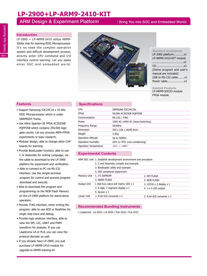
LP-2900+LP-ARM9-2410-KITARM Design & Experiment Platform / Bring You into SOC and Embedded World/
CPU
FPGA
Communication
Power
Frequency Range
Dimension
Weight
Operation Altitude
Operation Humidity
Operation Temperature
SAMSUNG S3C24C10x
XILINX XC3S250E PQFP208
RS-232 / JTAG
100V AC~240V AC (Auto-Switching)
50/60Hz
320 x 226 x 30/85.6mm
3.5Kg
Up to 5000m
20% to 70% (non-condensing)
+5℃ ~ +45℃
ARM SOC Unit 1. Establish development environment and procedure
2. C and Assembly compile and example.
3. Bootloader utility and example.
4. SOC peripheral experiment
Memory Unit 1. I²C EEPROM
3. NAND FLASH
Output Unit 1. 8x8 two colors dot matrix LED x 1
3. 6 digit, 7 segment display x 1
5. Buzzer x 1
Linear Unit 1. 8 bit D/A converter x 2
• Leaptronix LA-2025 / LA-2050 / PLA-1016 / PLA-2532
2. SPI FLASH
4. NOR FLASH
2. LCD16 x 2 display x 1
4. 3 x 4 LED output
2. 8 bit A/D converter x 1
Specifications
Experimental Contents
Recommended Bundling Instruments
IntroductionLP-2900 + LP-ARM9-2410 utilize ARM9-32bits chip for learning RISC Microprocessor.I t ’s no need the complex operat ionsystem and difficult development process,directly enter CPU command and I/Ointerface control learning. Let you easilye n t e r S O C a n d e m b e d d e d w o r l d .
• Support Samsung S3C24C10 x 32-bits
RISC Microprocessor which is under
SARM920T frame.
• Use Xilinx Spartan-3E FPGA XC3S250E
PQFP208 which contains 250,000 logic
gate counts. Let you process ARM+FPGA
experiments or topic research.
• Modular design, able to change other CUP
boards for learning
• Provide BootLoader function, able to use
C or Assembly for writing Language, via
the cable to download to the LP-2900
platform for experiment and verification.
• Able to connect to PC via RS-232
interface. Use the simple terminal
program for control and process program
download and execute.
• Able to download the program and
programming on the NOR Flash Memory
on the LP-2900 platform for stand-alone
operation.
• Provide JTAG interface, when writing the
program, able to use ADS or RealView for
single step trace and debug.
• Provide logic analyzer interface, able to
view the SPI, I2C, UART and PWM
waveform for analysis. If you use
Leaptronix LA or PLA, you can view the
protocol decoder as well.
• If you already have LP-2900, you just
purchase LP-ARM9-2410 module for
upgrade to ARM9 training kit
Features
Standard AccessoriesLP-2900 platform............x1LP-ARM9-2410-KIT module.....................................x1CD.................................x1(Demo program and user’s manual are included)USB to RS-232 cable........x1Power cable....................x1
Related ProductsLP-ARM9-SOCIO module FPGA module
B04 B 09
Learning Kits Series
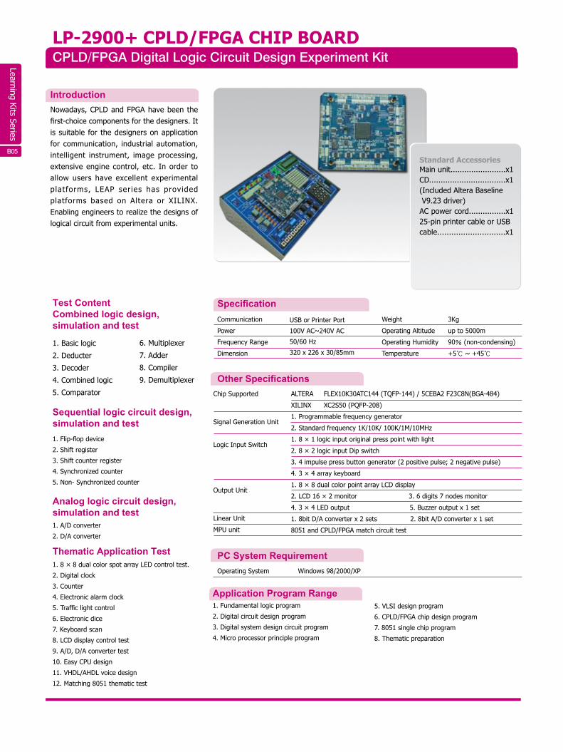
LP-2900+ CPLD/FPGA CHIP BOARDCPLD/FPGA Digital Logic Circuit Design Experiment Kit
IntroductionNowadays, CPLD and FPGA have been the first-choice components for the designers. It is suitable for the designers on application for communication, industrial automation, intelligent instrument, image processing, extensive engine control, etc. In order to allow users have excellent experimental platforms, LEAP ser ies has provided platforms based on Altera or XILINX. Enabling engineers to realize the designs of logical circuit from experimental units.
Standard AccessoriesMain unit........................x1CD.................................x1(Included Altera Baseline V9.23 driver)AC power cord................x125-pin printer cable or USB cable.............................x1
SpecificationTest ContentCombined logic design, simulation and test
Sequential logic circuit design,simulation and test1. Flip-flop device
2. Shift register
3. Shift counter register
4. Synchronized counter
5. Non- Synchronized counter
Analog logic circuit design, simulation and test1. A/D converter
2. D/A converter
Thematic Application Test
1. Basic logic
2. Deducter
3. Decoder
4. Combined logic
5. Comparator
6. Multiplexer
7. Adder
8. Compiler
9. Demultiplexer
1. 8 × 8 dual color spot array LED control test.
2. Digital clock
3. Counter
4. Electronic alarm clock
5. Traffic light control
6. Electronic dice
7. Keyboard scan
8. LCD display control test
9. A/D, D/A converter test
10. Easy CPU design
11. VHDL/AHDL voice design
12. Matching 8051 thematic test
PC System RequirementOperating System Windows 98/2000/XP
Application Program Range1. Fundamental logic program
2. Digital circuit design program
3. Digital system design circuit program
4. Micro processor principle program
5. VLSI design program
6. CPLD/FPGA chip design program
7. 8051 single chip program
8. Thematic preparation
ALTERA FLEX10K30ATC144 (TQFP-144) / 5CEBA2 F23C8N(BGA-484)
XILINX XC2S50 (PQFP-208)
1. Programmable frequency generator
2. Standard frequency 1K/10K/ 100K/1M/10MHz
1. 8 × 1 logic input original press point with light
2. 8 × 2 logic input Dip switch
3. 4 impulse press button generator (2 positive pulse; 2 negative pulse)
4. 3 × 4 array keyboard
1. 8 × 8 dual color point array LCD display
2. LCD 16 × 2 monitor 3. 6 digits 7 nodes monitor
4. 3 × 4 LED output 5. Buzzer output x 1 set
1. 8bit D/A converter x 2 sets 2. 8bit A/D converter x 1 set
8051 and CPLD/FPGA match circuit test
Chip Supported
Signal Generation Unit
Logic Input Switch
Output Unit
Linear Unit
MPU unit
Other Specifications
Communication
Power
Frequency Range
Dimension
USB or Printer Port
100V AC~240V AC
50/60 Hz
320 x 226 x 30/85mm
Weight
Operating Altitude
Operating Humidity
Temperature
3Kg
up to 5000m
90% (non-condensing)
+5℃ ~ +45℃
B05
Learning Kits Series
Display:240 x 128 LCD
Emulating:1. TTL IN (x28) Pin 2. TTL OUT (x28) Pin 3. O.C. OUT (x6) Pin
Control keypad:FUNC, ESC, ↑, ↓,
Logic Switch:S1~S8
Signal Generator:
1. A, /A →100 ms Pulse 2. B, /B →100 ms Pulse
3. Clock:1 Hz/10 Hz/100 Hz/1 KHz/10 KHz/100 KHz/1MHz
4. CLK/2, CLK/4, CLK/8, CLK/16, CLK/32, CLK/64, CLKIN
Standard Circuit Module:
1. Common anode LED display x 8 2. Common cathode LED display x 8
3. Isolated common anode 7 segment display x 2
4. 8 x 8 monochrome dot matrix LED 5. BUZZER unit 6. VH, VL, common point x 4
Advanced Circuit Module:
1. 555 Circuit unit (a. Mono-stable oscillator / b. Non-stable oscillator)
2. D/A unit 4bit 3. A/D unit 7bit 4. PULL UP circuit experiment
Advanced Software Module:
Allow users to edit and revise experimental circuits.
1. To download experimental circuits to experimental lab
2. To create experimental circuits for various certificated levels
LP-2600 Smart Logic Design Experimental Kit
SpecificationCommunication
Power
Frequency Range
Dimension
Weight
Operating Altitude
Operating Humidity
Temperature
USB1.1
90V AC~260V AC
50/60 Hz
320 x 226 x 30/85mm
2.8Kg
up to 5000m
90% (non-condensing)
+5℃ ~ +45℃
Other Specifications
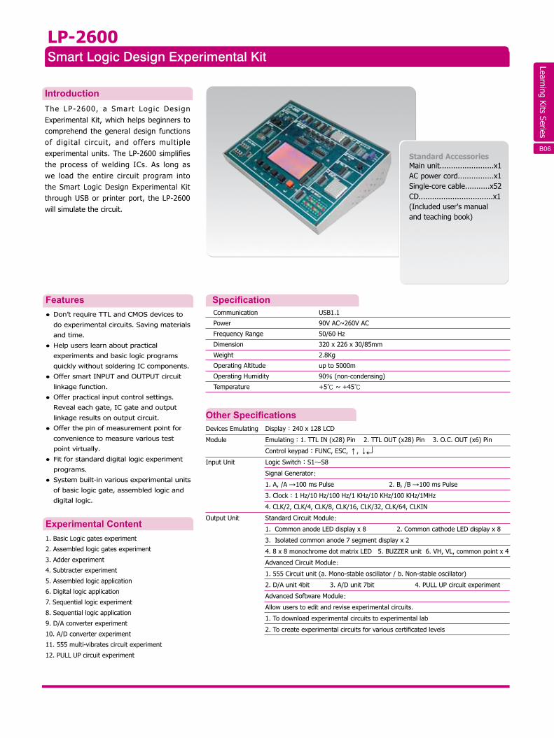
IntroductionThe LP-2600, a Smart Logic Design Experimental Kit, which helps beginners to comprehend the general design functions of digital circuit, and offers multiple experimental units. The LP-2600 simplifies the process of welding ICs. As long as we load the entire circuit program into the Smart Logic Design Experimental Kit through USB or printer port, the LP-2600 will simulate the circuit.
● Don’t require TTL and CMOS devices to
do experimental circuits. Saving materials
and time.
● Help users learn about practical
experiments and basic logic programs
quickly without soldering IC components.
● Offer smart INPUT and OUTPUT circuit
linkage function.
● Offer practical input control settings.
Reveal each gate, IC gate and output
linkage results on output circuit.
● Offer the pin of measurement point for
convenience to measure various test
point virtually.
● Fit for standard digital logic experiment
programs.
● System built-in various experimental units
of basic logic gate, assembled logic and
digital logic.
Features
Standard AccessoriesMain unit........................x1AC power cord................x1Single-core cable...........x52CD.................................x1 (Included user's manual and teaching book)
Experimental Content1. Basic Logic gates experiment
2. Assembled logic gates experiment
3. Adder experiment
4. Subtracter experiment
5. Assembled logic application
6. Digital logic application
7. Sequential logic experiment
8. Sequential logic application
9. D/A converter experiment
10. A/D converter experiment
11. 555 multi-vibrates circuit experiment
12. PULL UP circuit experiment
Devices Emulating
Module
Input Unit
Output Unit
B12 B06
Learning Kits Series
B17
75 cm
2 m /s
2.5 m /s
12V
(12 m /s): 2.3A
Sealed deep cycle lead-acid battery
8.6 kg (including battery)
445 x 240 x 205mm
Blade cycle diameter
Start wind speed
Start charging wind speed
Charging voltage
Charge current
Battery
Weight
Dimension
LP-2025Portable Wind Power Generation Kit
Applications
Specification
1.Portable monitoring system experiment.
2.Small wind power generation systems and power suppply experiments.
3. For the green energy industry thematic studies. Using the different accessories to understand the
wind power system.
4. Able to use for small power utility applications:
A. Garden and landscape lighting.
B. Portable LED or low power comsumption use.
C. Use of outdoor activities.
D. The various lighting for family use.
Introduction
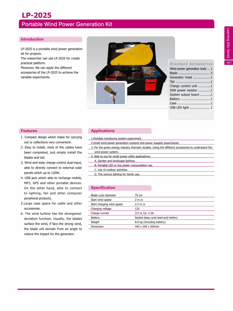
LP-2025 is a portable wind power generation kit for projects. The researcher can use LP-2025 for createpractical platform. Moreover, We can apply the different accessories of the LP-2025 to achieve the variable experiments.
1. Compact design which make for carrying
out or collections very convenient.
2. Easy to install, most of the cables have
been completed, just simply install the
blades and tail.
3. Wind and solar charge control dual-input,
able to directly connect to external solar
panels which up to 120W.
4. USB jack which able to recharge mobile,
MP3, GPS and other portable devices.
On the other hand, able to connect
to lighting, fan and other computer
peripheral products.
5.Large case space for cable and other
accessories.
6. The wind turbine has the strongwind-
deviation function. Usually, the blades
surface the wind, if face the strong wind,
the blade will deviate from an angle to
reduce the impact for the generator.
Features
S tand ard Ac c essor iesWind power generation body .. 1Blade ................................ 3Generator head ..................1Tail ....................................1Charge control unit .............150W power resistor .............1System output board ...........1Battery ...............................1Case ...................................1USB LED light ..................... 1
B07B18
Learning Kits Series
Standard Accessories1. Main unit............................x12. CD......................................x1
( i n c l u d e d u s e r ' s m a n u a l , teaching book, source code, example)
3. No. 4 rechargeable battery ...x44 .Adap to r 12V 0 .5A , pos i t i ve
pole inside..........................x15. USB cable...........................x16. 10cm 2pin cable with 3.96mm
terminal..............................x17. 30cm 2pin cable with 3.96mm
terminal..............................x28. 34cm 3pin cable with 3.96mm terminal...............................x5
Optional Accessories:1. Halogen lamp, 250W2. Wind power generation kit LP-2025
6W
8V (MAX)
780mA (MAX)
USB
DC 9V~12V/500mA
335 x 240 x 75mm
2.5 kg
Output Power Of Solar
Output Voltage of Solar Power
Output Current of Solar Power
Communication Interface
System Power
Dimensiun
Weight
Teach users the way to connect different module and design operating mode of each module so that users can comprehend the basic principle and application of solar power battery.
1. Observe I/V, V/P and MPP characteristic curve of solar power module2. Set the output (I/V) of solar power module according to the incident angle3. Design of DC TO DC CONVERTER Module4. Experiment of DC TO AC INVERTER Module5. Experiment of basic load and observe the I/V of solar power module6. Charging and discharge function of battery7. MPPT algorithm8. Integrate all experiments above so users can exactly know regeneration and use of green power
GP-6WGreen Power Lab
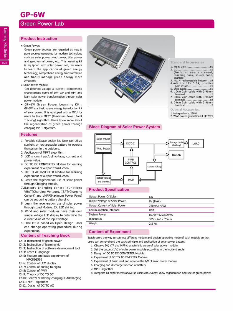
Block Diagram of Solar Power System
Product Specification
Content of Experiment
Product Instruction● Green Power:
Green power sources are regarded as new &pure sources generated by modern technologysuch as solar power, wind power, tidal powerand geothermal power, etc. This learning kitis equipped with solar power cell, for usersto learn the application of green energytechnology, comprehend energy transformationand f inal ly manage green energy moreefficiently.
● Solar power module: Get different voltage & current, comprehendcharacteristic curve of I/V, V/P and MPP andlearn solar power transformation through solarpower module.
● G P - 6 W G r e e n Po w e r L e a r n i n g K i t :GP-6W is a basic green energy transduction kitof solar power. It is equipped with a MCU forusers to learn MPPT (Maximum Power PointTracking) algorithm. Users know more aboutthe regeneration of green power throughchanging MPPT algorithm.
1. Portable suitcase design kit. User can utilizesunlight or rechargeable battery to operatethe system in the outdoors.
2. Application of MPPT algorithm.3. LCD shows input/out voltage, current and
power value.4. DC TO DC CONVERTER Module for learning
experiment of output transduction.5. DC TO AC INVERTER Module for learning
experiment of output transduction.6. Learn the regeneration use of solar power
through Charging Module.7 .Ba t t e r y cha rg ing con t ro l f unc t i on :
VBAT(Charging Voltage), IBAT(ChargingCurrent) and VMPP(Maximum Power Point)can be set during battery charging
8. Learn the regeneration use of solar powerthrough Load Module. EX: LED shining.
9. Wind and solar modules have their ownsimple voltage LED display to determine thecurrent value of the input voltage.
10.The kit is based on Open Design. Usercan change operating procedure duringexperiment.
Ch 1: Instruction of green powerCh 2: Instruction of learning kitCh 3: Instruction of software development toolCh 4: Learn C languageCh 5: Feature and basic experiment of MPC82G516Ch 6: Control of LCM displayCh 7: Control of analog to digital Ch 8: Control of PWMCh 9: Theory of DC TO DCCh10: Control of battery charging & dischargingCh11: MPPT algorithmCh12: Design of DC TO AC
Features
Content of Teaching Book
B08 B19
Solar Power
Wind Power
Detect Voltage
and Current
DC/D C LOADStorage device(Battery)
DC/AC
PWMCONTROL
MCU
Detect Voltage
Learning Kits Series
● Use the simple example programs to control the peripheral devices, included the LCD, relay (Relay-1
& Relay-2), electromagnet (Solenoid), LED (LED-1 to LED-4), reed switch (Sensor-1), glass breaking
(Sensor-2), external data entry (Input Port IP-1 to IP-4), status input (SW-1 & SW-2) and data set (DIP
Switch-S1).
● Read the data of ISO 14443A RFID tag and show the UID code on LCD.
● Read the data of ISO 15693 RFID tag and show the UID code on LCD. Upload the data of ISO 15693
RFID tag to PC in ASCII code format via USB (or RS-232) and show the ID on Super Terminal.
● Execute ISO 14443A RFID tag reading. Verify the UID with the first I2C memory data and see if they
are the same. The result will show on the LED.
● Control the RTC, real time clock, included year, month, date, hour, minute and second.
● Read, write and erase for the single user data area of the ISO 15693 RFID tag.
● Induct several ISO 15693 tags and send UID to PC on Super Terminal via USB.
● Read, write and erase function example for the internal area of ISO 14443A Mifare Card.
● Create the record of entry. LP-2010 will store the ID code and entry time within the second I2C
memory. The user can also read and delete the record via Super Terminal on the PC.
● Integrate above experiments and create simple access control system that including workers
database, entry time, locked control, glass breaking detect and alarm system.
LP-2010RFID Experimental Trainer
Specification
Test Content
Communication
Operating Voltage Input Port
Operating Voltage RELAY 1,2
Power
Frequency Range
Dimension
Weight
USB˴RS-232
5~24V DC (MAX)
1A/125V AC, 2A/30V DC
100V AC~240V AC
50/60 Hz
320 x 226 x 30/85mm
2.5 kg
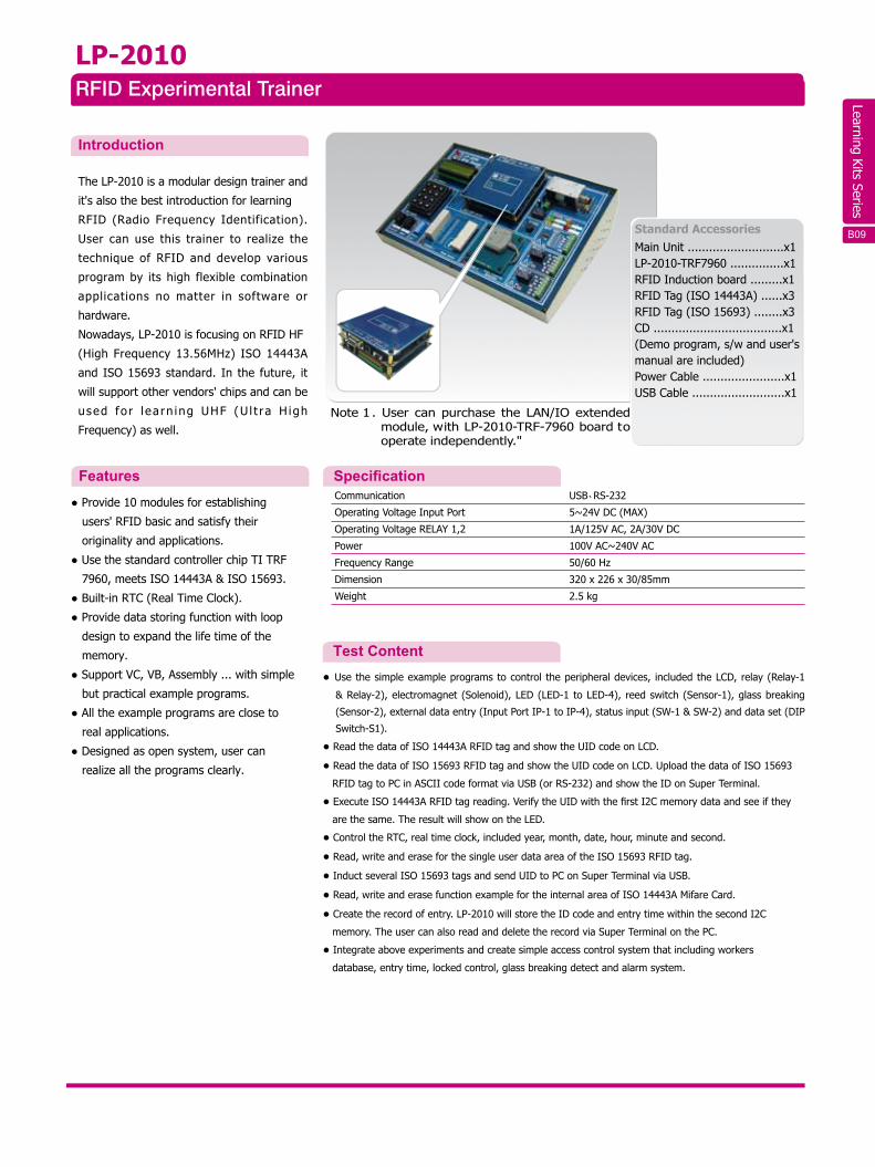
Introduction
The LP-2010 is a modular design trainer and
it's also the best introduction for learning
RFID (Radio Frequency Identification).
User can use this trainer to realize the
technique of RFID and develop various
program by its high flexible combination
applications no matter in software or
hardware.
Nowadays, LP-2010 is focusing on RFID HF
(High Frequency 13.56MHz) ISO 14443A
and ISO 15693 standard. In the future, it
will support other vendors' chips and can be
used fo r l ea rn ing UHF (U l t ra H igh
Frequency) as well.
● Provide 10 modules for establishing
users' RFID basic and satisfy their
originality and applications.
● Use the standard controller chip TI TRF
7960, meets ISO 14443A & ISO 15693.
● Built-in RTC (Real Time Clock).
● Provide data storing function with loop
design to expand the life time of the
memory.
● Support VC, VB, Assembly ... with simple
but practical example programs.
● All the example programs are close to
real applications.
● Designed as open system, user can
realize all the programs clearly.
Features
Standard AccessoriesMain Unit ...........................x1LP-2010-TRF7960 ...............x1RFID Induction board .........x1RFID Tag (ISO 14443A) ......x3RFID Tag (ISO 15693) ........x3CD ....................................x1(Demo program, s/w and user's manual are included)Power Cable .......................x1USB Cable ..........................x1
B20
Note 1 . User can purchase the LAN/IO extended module, with LP-2010-TRF-7960 board to operate independently."
B09
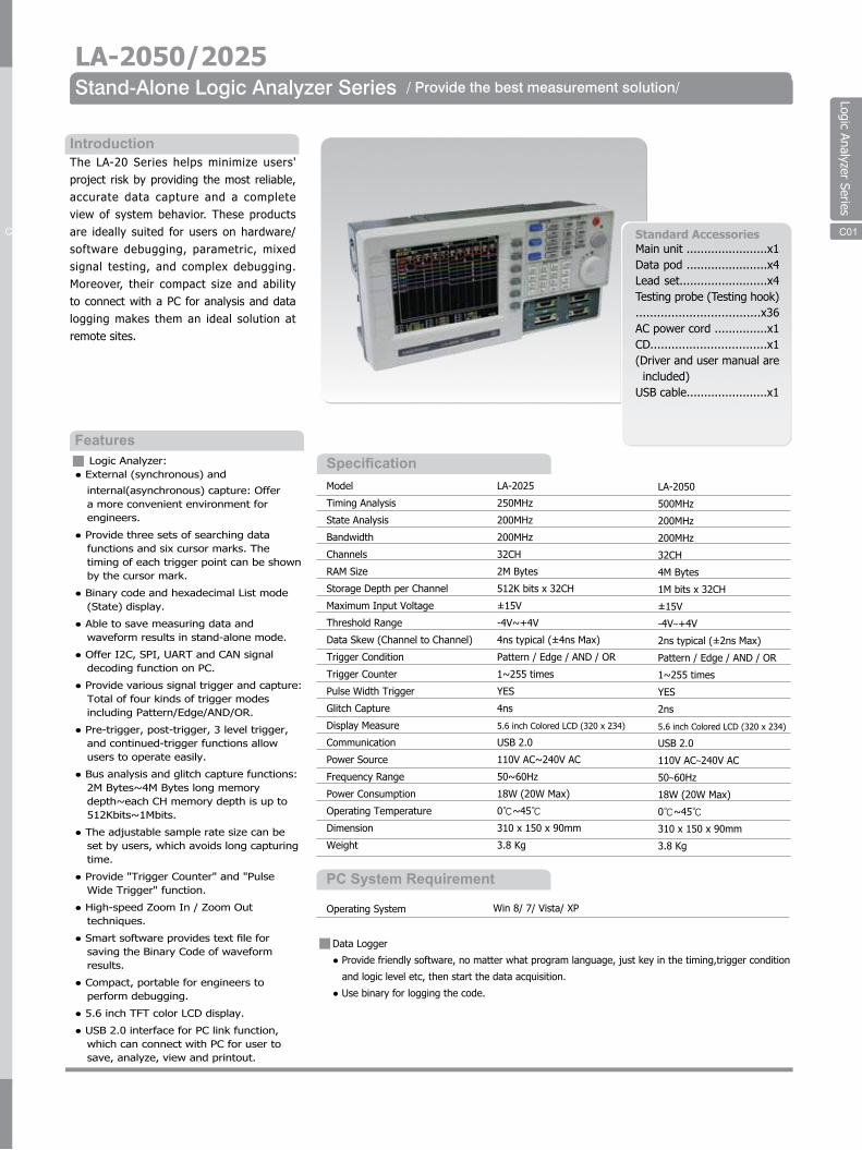
Logic Analyzer Series
LA-2050/2025Stand-Alone Logic Analyzer Series / Provide the best measurement solution/
SpecificationModel
Timing Analysis
State Analysis
Bandwidth
Channels
RAM Size
Storage Depth per Channel
Maximum Input Voltage
Threshold Range
Data Skew (Channel to Channel)
Trigger Condition
Trigger Counter
Pulse Width Trigger
Glitch Capture
Display Measure
Communication
Power Source
Frequency Range
Power Consumption
Operating Temperature
Dimension
Weight
LA-2025
250MHz
200MHz
200MHz
32CH
2M Bytes
512K bits x 32CH
±15V
-4V~+4V
4ns typical (±4ns Max)
Pattern / Edge / AND / OR
1~255 times
YES
4ns
5.6 inch Colored LCD (320 x 234)
USB 2.0
110V AC~240V AC
50~60Hz
18W (20W Max)
0℃~45℃
310 x 150 x 90mm
3.8 Kg
LA-2050
500MHz
200MHz
200MHz
32CH
4M Bytes
1M bits x 32CH
±15V
-4V~+4V
2ns typical (±2ns Max)
Pattern / Edge / AND / OR
1~255 times
YES
2ns
5.6 inch Colored LCD (320 x 234)
USB 2.0
110V AC~240V AC
50~60Hz
18W (20W Max)
0℃~45℃
310 x 150 x 90mm
3.8 Kg
IntroductionThe LA-20 Series helps minimize users' project risk by providing the most reliable, accurate data capture and a complete view of system behavior. These products are ideally suited for users on hardware/software debugging, parametric, mixed signal testing, and complex debugging. Moreover, their compact size and ability to connect with a PC for analysis and data logging makes them an ideal solution at remote sites.
Logic Analyzer:● External (synchronous) and
internal(asynchronous) capture꞉ Offera more convenient environment forengineers.
● Provide three sets of searching datafunctions and six cursor marks. Thetiming of each trigger point can be shownby the cursor mark.
● Binary code and hexadecimal List mode(State) display.
● Able to save measuring data andwaveform results in stand-alone mode.
● Offer I2C, SPI, UART and CAN signaldecoding function on PC.
● Provide various signal trigger and capture꞉Total of four kinds of trigger modesincluding Pattern/Edge/AND/OR.
● Pre-trigger, post-trigger, 3 level trigger,and continued-trigger functions allowusers to operate easily.
● Bus analysis and glitch capture functions:2M Bytes~4M Bytes long memorydepth~each CH memory depth is up to512Kbits~1Mbits.
● The adjustable sample rate size can beset by users, which avoids long capturingtime.
● Provide "Trigger Counter" and "PulseWide Trigger" function.
● High-speed Zoom In / Zoom Outtechniques.
● Smart software provides text file forsaving the Binary Code of waveformresults.
● Compact, portable for engineers toperform debugging.
● 5.6 inch TFT color LCD display.
● USB 2.0 interface for PC link function,which can connect with PC for user tosave, analyze, view and printout.
Standard AccessoriesMain unit .......................x1Data pod .......................x4Lead set.........................x4Testing probe (Testing hook) ...................................x36AC power cord ...............x1CD.................................x1 (Driver and user manual are included)USB cable.......................x1
Features
PC System Requirement
Operating System
Data Logger
● Provide friendly software, no matter what program language, just key in the timing,trigger condition
and logic level etc, then start the data acquisition.
● Use binary for logging the code.
Win 8/ 7/ Vista/ XP
C02 C01
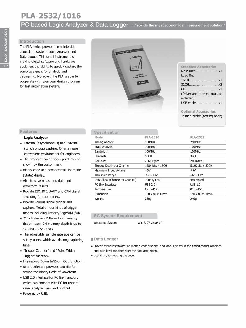
Logic Analyzer Series
PLA-2532/1016PC-based Logic Analyzer & Data Logger
Model
Timing Analysis
State Analysis
Bandwidth
Channels
RAM Size
Storage Depth per Channel
Maximum Input Voltage
Threshold Range
Data Skew (Channel to Channel)
PC Link Interface
Temperature
Dimension
Weight
PLA-1016
100MHz
100MHz
100MHz
16CH
256K Bytes
128K bits x 16CH
±5V
-4V~+4V
10ns typical
USB 2.0
0℃~45℃
150 x 80 x 30mm
230g
PLA-2532
250MHz
100MHz
100MHz
32CH
2M Bytes
512K bits x 32CH
±5V
-4V~+4V
4ns typical
USB 2.0
0℃~45℃
150 x 80 x 30mm
240g
IntroductionThe PLA series provides complete dateacquisition system, Logic Analyzer andData Logger. This small instrument ismaking digital software and hardwaredesigners the ability to quickly capture thecomplex signals for analysis anddebugging. Moreover, the PLA is able tocooperate with your own design programfor test automation system.
Logic Analyzer
● Internal (asynchronous) and External
(synchronous) capture: Offer a more
convenient environment for engineers.
● The timing of each trigger point can be
shown by the cursor mark.
● Binary code and hexadecimal List mode
(State) display.
● Able to save measuring data and
waveform results.
● Provide I2C, SPI, UART and CAN signal
decoding function on PC.
● Provide various signal trigger and
capture: Total of four kinds of trigger
modes including Pattern/Edge/AND/OR.
● 256K Bytes ~ 2M Bytes long memory
depth : each CH memory depth is up to
128Kbits ~ 512Kbits.
● The adjustable sample rate size can be
set by users, which avoids long capturing
time.
● “Trigger Counter” and “Pulse Width
Trigger” function.
● High-speed Zoom In/Zoom Out function.
● Smart software provides text file for
saving the Binary Code of waveform.
● USB 2.0 interface for PC link function,
which can connect with PC for user to
save, analyze, view and printout.
● Powered by USB.
Features
Standard AccessoriesMain unit........................x1Lead Set16CH.............................x132CH.............................x2CD.................................x1 (Driver and user manual are included)USB cable.......................x1
Optional AccessoriesTesting probe (testing hook)
Specification
PC System Requirement
Data Logger
Operating System Win 8/ 7/ Vista/ XP
● Provide friendly software, no matter what program language, just key in the timing,trigger condition
and logic level etc, then start the data acquisition.
● Use binary for logging the code.
C03C02
/ P rovide the most economical measurement solution/
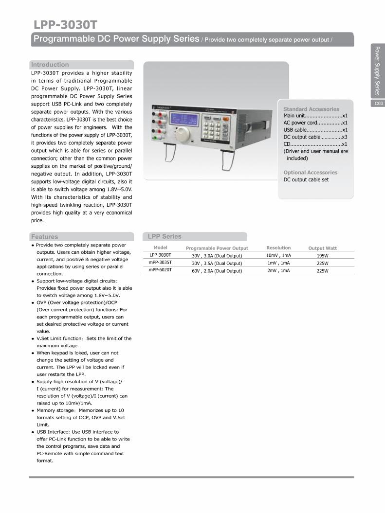
Power Supply Series
C03
LPP SeriesModel
LPP-3030T
mPP-3035T
mPP-6020T
Programable Power Output
30V , 3.0A (Dual Output)
30V , 3.5A (Dual Output)
60V , 2.0A (Dual Output)
Resolution
10mV , 1mA
1mV , 1mA
2mV , 1mA
LPP-3030TProgrammable DC Power Supply Series / Provide two completely separate power output /
IntroductionLPP-3030T provides a higher stability in terms of traditional Programmable DC Power Supply. LPP-3030T, l inear programmable DC Power Supply Series support USB PC-Link and two completely separate power outputs. With the various characteristics, LPP-3030T is the best choice of power supplies for engineers. With the functions of the power supply of LPP-3030T, it provides two completely separate power output which is able for series or parallel connection; other than the common power supplies on the market of positive/ground/negative output. In addition, LPP-3030T supports low-voltage digital circuits, also it is able to switch voltage among 1.8V~5.0V. With its characteristics of stability and high-speed twinkling reaction, LPP-3030T provides high quality at a very economical price.
● Provide two completely separate power
outputs. Users can obtain higher voltage,
current, and positive & negative voltage
applications by using series or parallel
connection.
● Support low-voltage digital circuits:
Provides fixed power output also it is able
to switch voltage among 1.8V~5.0V.
● OVP (Over voltage protection)/OCP
(Over current protection) functions: For
each programmable output, users can
set desired protective voltage or current
value.
● V.Set Limit function: Sets the limit of the
maximum voltage.
● When keypad is loked, user can not
change the setting of voltage and
current. The LPP will be locked even if
user restarts the LPP.
● Supply high resolution of V (voltage)/
I (current) for measurement: The
resolution of V (voltage)/I (current) can
raised up to 10mV/1mA.
● Memory storage: Memorizes up to 10
formats setting of OCP, OVP and V.Set
Limit.
● USB Interface: Use USB interface to
offer PC-Link function to be able to write
the control programs, save data and
PC-Remote with simple command text
format.
Features
Standard AccessoriesMain unit........................x1AC power cord................x1USB cable.......................x1DC output cable…………...x3CD.................................x1 (Driver and user manual are included)
Optional AccessoriesDC output cable set
C04 C03
Output Watt
195W
225W
225W
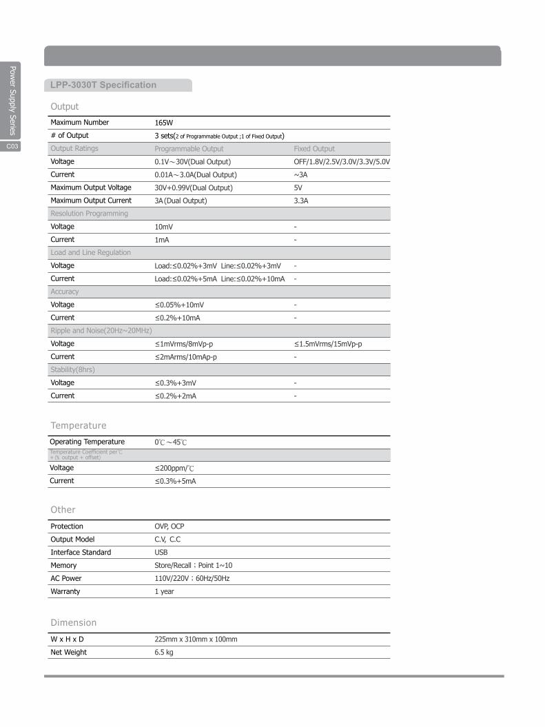
Power Supply Series
LPP-3030T SpecificationLPP-3030T Programmable DC Power Supply Specifications
Maximum Number
# of Output
Output Ratings
Voltage
Current
Maximum Output Voltage
Maximum Output Current
Resolution Programming
Voltage
Current
Load and Line Regulation
Voltage
Current
Accuracy
Voltage
Current
Ripple and Noise(20Hz~20MHz)
Voltage
Current
Stability(8hrs)
Voltage
Current
165W
3 sets(2 of Programmable Output ;1 of Fixed Output)
Programmable Output
0.1V~30V(Dual Output)
0.01A~3.0A(Dual Output)
30V+0.99V(Dual Output)
3A(Dual Output)
10mV
1mA
Load:≤0.02%+3mV Line:≤0.02%+3mV
Load:≤0.02%+5mA Line:≤0.02%+10mA
≤0.05%+10mV
≤0.2%+10mA
≤1mVrms/8mVp-p
≤2mArms/10mAp-p
≤0.3%+3mV
≤0.2%+2mA
Fixed Output
OFF/1.8V/2.5V/3.0V/3.3V/5.0V
~3A
5V
3.3A
-
-
-
-
-
-
≤1.5mVrms/15mVp-p
-
-
-
Output
Operating Temperature
Voltage
Current
0℃~45℃
≤200ppm/℃
≤0.3%+5mA
Temperature
Protection
Output Model
Interface Standard
Memory
AC Power
Warranty
OVP, OCP
C.V, C.C
USB
Store/Recall;Point 1~10
110V/220V;60Hz/50Hz
1 year
Other
W x H x D
Net Weight
225mm x 310mm x 100mm
6.5 kg
Dimension
Temperature Coefficient per℃+(% output + offset)
A05C03
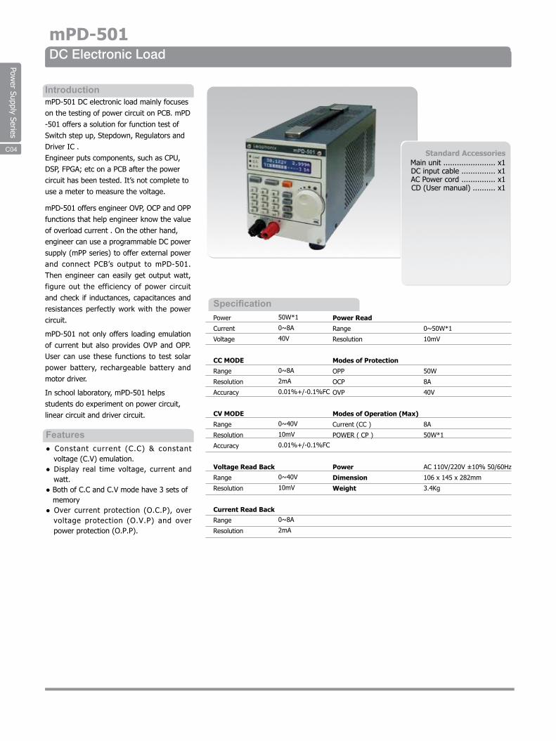
Power Supply Series
mPD-501DC Electronic Load
Specification
IntroductionmPD-501 DC electronic load mainly focuseson the testing of power circuit on PCB. mPD-501 offers a solution for function test ofSwitch step up, Stepdown, Regulators andDriver IC .Engineer puts components, such as CPU,DSP, FPGA; etc on a PCB after the powercircuit has been tested. It’s not complete touse a meter to measure the voltage.
mPD-501 offers engineer OVP, OCP and OPP functions that help engineer know the value of overload current . On the other hand,engineer can use a programmable DC power supply (mPP series) to offer external power and connect PCB’s output to mPD-501. Then engineer can easily get output watt, figure out the efficiency of power circuit and check if inductances, capacitances and resistances perfectly work with the power circuit.
mPD-501 not only offers loading emulation of current but also provides OVP and OPP. User can use these functions to test solar power battery, rechargeable battery and motor driver.
In school laboratory, mPD-501 helpsstudents do experiment on power circuit,linear circuit and driver circuit.
● Constant current (C.C) & constantvoltage (C.V) emulation.
● Display real time voltage, current andwatt.
● Both of C.C and C.V mode have 3 sets ofmemory
● Over current protection (O.C.P), overvoltage protection (O.V.P) and overpower protection (O.P.P).
Features
Standard AccessoriesMain unit ....................... x1DC input cable ............... x1AC Power cord ............... x1CD (User manual) .......... x1
C06
50W*1
0~8A
40V
0~8A
2mA
0.01%+/-0.1%FC
0~40V
10mV
0.01%+/-0.1%FC
0~40V
10mV
0~8A
2mA
0~50W*1
10mV
50W
8A
40V
8A
50W*1
AC 110V/220V ±10% 50/60Hz
106 x 145 x 282mm
3.4Kg
Power
Current
Voltage
CC MODE
Range
Resolution
Accuracy
CV MODE
Range
Resolution
Accuracy
Voltage Read Back
Range
Resolution
Current Read Back
Range
Resolution
Power Read
Range
Resolution
Modes of Protection
OPP
OCP
OVP
Modes of Operation (Max)
Current (CC )
POWER ( CP )
Power
Dimension
Weight
C04
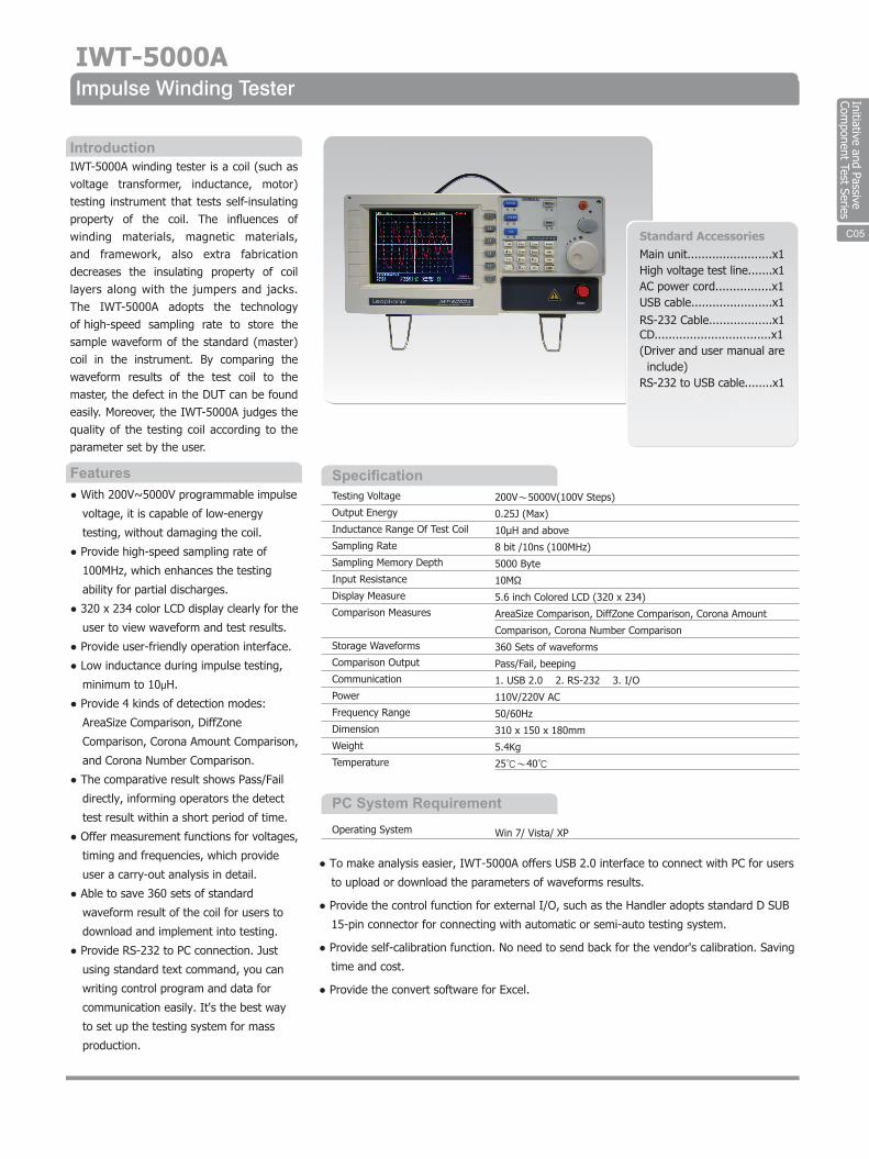
Initiative and Passive Com
ponent Test Series
C06
IWT-5000AImpulse Winding Tester
Specification
IntroductionIWT-5000A winding tester is a coil (such as voltage transformer, inductance, motor) testing instrument that tests self-insulating property of the coil. The influences of winding materials, magnetic materials, and framework, also extra fabrication decreases the insulating property of coil layers along with the jumpers and jacks. The IWT-5000A adopts the technology of high-speed sampling rate to store the sample waveform of the standard (master) coil in the instrument. By comparing the waveform results of the test coil to the master, the defect in the DUT can be found easily. Moreover, the IWT-5000A judges the quality of the testing coil according to the parameter set by the user.
● With 200V~5000V programmable impulse
voltage, it is capable of low-energy
testing, without damaging the coil.
● Provide high-speed sampling rate of
100MHz, which enhances the testing
ability for partial discharges.
● 320 x 234 color LCD display clearly for the
user to view waveform and test results.
● Provide user-friendly operation interface.
● Low inductance during impulse testing,
minimum to 10μH.
● Provide 4 kinds of detection modes:
AreaSize Comparison, DiffZone
Comparison, Corona Amount Comparison,
and Corona Number Comparison.
● The comparative result shows Pass/Fail
directly, informing operators the detect
test result within a short period of time.
● Offer measurement functions for voltages,
timing and frequencies, which provide
user a carry-out analysis in detail.
● Able to save 360 sets of standard
waveform result of the coil for users to
download and implement into testing.
● Provide RS-232 to PC connection. Just
using standard text command, you can
writing control program and data for
communication easily. It's the best way
to set up the testing system for mass
production.
Features
Standard AccessoriesMain unit........................x1High voltage test line.......x1AC power cord................x1USB cable.......................x1RS-232 Cable..................x1CD.................................x1(Driver and user manual are include) RS-232 to USB cable........x1
Testing Voltage
Output Energy
Inductance Range Of Test Coil
Sampling Rate
Sampling Memory Depth
Input Resistance
Display Measure
Comparison Measures
Storage Waveforms
Comparison Output
Communication
Power
Frequency Range
Dimension
Weight
Temperature
200V~5000V(100V Steps)
0.25J (Max)
10μH and above
8 bit /10ns (100MHz)
5000 Byte
10MΩ
5.6 inch Colored LCD (320 x 234)
AreaSize Comparison, DiffZone Comparison, Corona Amount
Comparison, Corona Number Comparison
360 Sets of waveforms
Pass/Fail, beeping
1. USB 2.0 2. RS-232 3. I/O
110V/220V AC
50/60Hz
310 x 150 x 180mm
5.4Kg
25℃~40℃
PC System RequirementOperating System Win 7/ Vista/ XP
C07
● To make analysis easier, IWT-5000A offers USB 2.0 interface to connect with PC for users
to upload or download the parameters of waveforms results.
● Provide the control function for external I/O, such as the Handler adopts standard D SUB
15-pin connector for connecting with automatic or semi-auto testing system.
● Provide self-calibration function. No need to send back for the vendor's calibration. Saving
time and cost.
● Provide the convert software for Excel.
C05
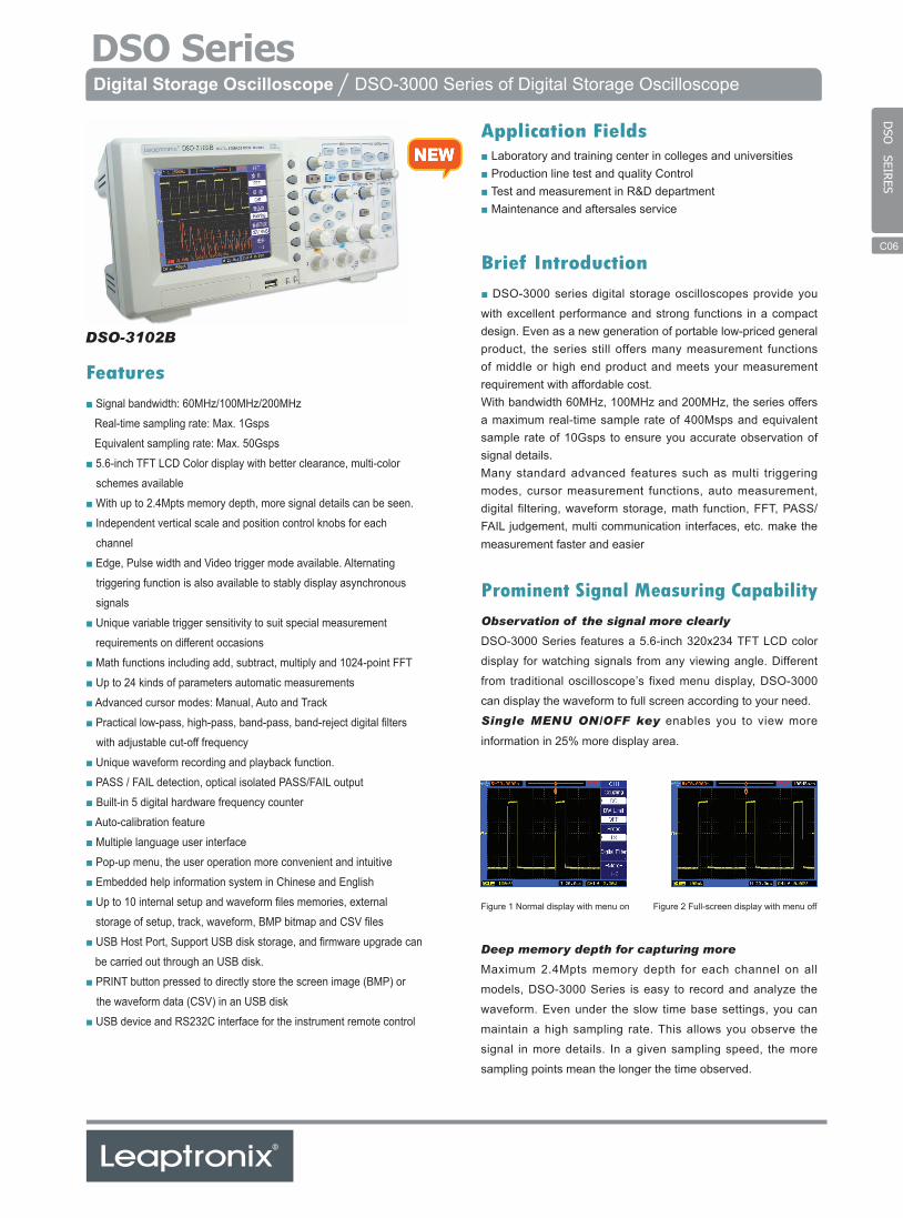
Features■ Signal bandwidth: 60MHz/100MHz/200MHz
Real-time sampling rate: Max. 1Gsps
Equivalent sampling rate: Max. 50Gsps
■ 5.6-inch TFT LCD Color display with better clearance, multi-color
schemes available
■ With up to 2.4Mpts memory depth, more signal details can be seen.
■ Independent vertical scale and position control knobs for each
channel
■ Edge, Pulse width and Video trigger mode available. Alternating
triggering function is also available to stably display asynchronous
signals
■ Unique variable trigger sensitivity to suit special measurement
requirements on different occasions
■ Math functions including add, subtract, multiply and 1024-point FFT
■ Up to 24 kinds of parameters automatic measurements
■ Advanced cursor modes: Manual, Auto and Track
■ Practical low-pass, high-pass, band-pass, band-reject digital filters
with adjustable cut-off frequency
■ Unique waveform recording and playback function.
■ PASS / FAIL detection, optical isolated PASS/FAIL output
■ Built-in 5 digital hardware frequency counter
■ Auto-calibration feature
■ Multiple language user interface
■ Pop-up menu, the user operation more convenient and intuitive
■ Embedded help information system in Chinese and English
■ Up to 10 internal setup and waveform files memories, external
storage of setup, track, waveform, BMP bitmap and CSV files
■ USB Host Port, Support USB disk storage, and firmware upgrade can
be carried out through an USB disk.
■ PRINT button pressed to directly store the screen image (BMP) or
the waveform data (CSV) in an USB disk
■ USB device and RS232C interface for the instrument remote control
Brief Introduction■ DSO-3000 series digital storage oscilloscopes provide you
with excellent performance and strong functions in a compact design. Even as a new generation of portable low-priced general product, the series still offers many measurement functions of middle or high end product and meets your measurement requirement with affordable cost.With bandwidth 60MHz, 100MHz and 200MHz, the series offers a maximum real-time sample rate of 400Msps and equivalent sample rate of 10Gsps to ensure you accurate observation of signal details.Many standard advanced features such as multi triggering modes, cursor measurement functions, auto measurement, digital filtering, waveform storage, math function, FFT, PASS/FAIL judgement, multi communication interfaces, etc. make the measurement faster and easier
Prominent Signal Measuring CapabilityObservation of the signal more clearly
DSO-3000 Series features a 5.6-inch 320x234 TFT LCD color
display for watching signals from any viewing angle. Different
from traditional oscilloscope’s fixed menu display, DSO-3000
can display the waveform to full screen according to your need.
Single MENU ON/OFF key enables you to view more
information in 25% more display area.
Deep memory depth for capturing more
Maximum 2.4Mpts memory depth for each channel on all
models, DSO-3000 Series is easy to record and analyze the
waveform. Even under the slow time base settings, you can
maintain a high sampling rate. This allows you observe the
signal in more details. In a given sampling speed, the more
sampling points mean the longer the time observed.
Application Fields■ Laboratory and training center in colleges and universities■ Production line test and quality Control■ Test and measurement in R&D department■ Maintenance and aftersales service
Digital Storage Oscilloscope / DSO-3000 Series of Digital Storage Oscilloscope
DSO-3102B
Figure 1 Normal display with menu on Figure 2 Full-screen display with menu off
DSO
SEIRES
C06
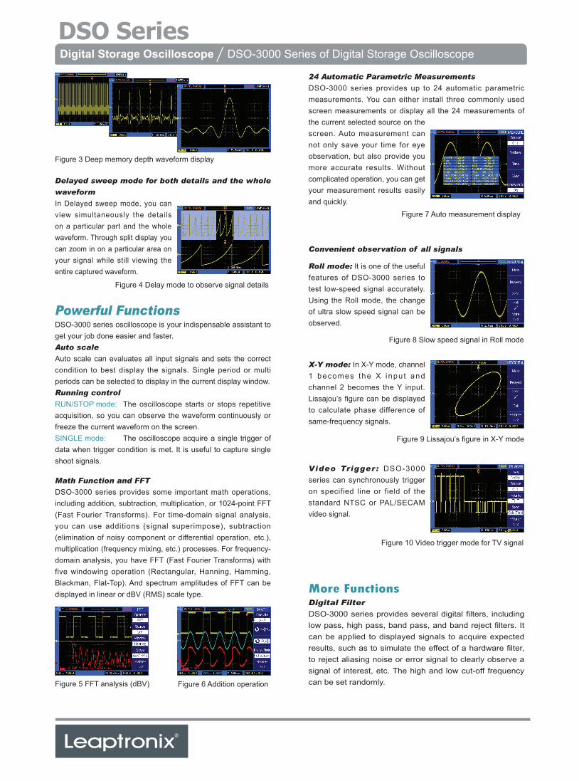
Delayed sweep mode for both details and the whole
waveform
In Delayed sweep mode, you can view simultaneously the details on a particular part and the whole waveform. Through split display you can zoom in on a particular area on your signal while still viewing the entire captured waveform.
Powerful FunctionsDSO-3000 series oscilloscope is your indispensable assistant to get your job done easier and faster.Auto scale
Auto scale can evaluates all input signals and sets the correct condition to best display the signals. Single period or multi periods can be selected to display in the current display window.Running control
RUN/STOP mode: The oscilloscope starts or stops repetitive acquisition, so you can observe the waveform continuously or freeze the current waveform on the screen.SINGLE mode: The oscilloscope acquire a single trigger of data when trigger condition is met. It is useful to capture single shoot signals.
Math Function and FFT
DSO-3000 series provides some important math operations, including addition, subtraction, multiplication, or 1024-point FFT (Fast Fourier Transforms). For time-domain signal analysis, you can use additions (signal superimpose), subtraction (elimination of noisy component or differential operation, etc.), multiplication (frequency mixing, etc.) processes. For frequency-domain analysis, you have FFT (Fast Fourier Transforms) with five windowing operation (Rectangular, Hanning, Hamming, Blackman, Flat-Top). And spectrum amplitudes of FFT can be displayed in linear or dBV (RMS) scale type.
24 Automatic Parametric Measurements
DSO-3000 series provides up to 24 automatic parametric measurements. You can either install three commonly used screen measurements or display all the 24 measurements of the current selected source on the screen. Auto measurement can not only save your time for eye observation, but also provide you more accurate results. Without complicated operation, you can get your measurement results easily and quickly.
Convenient observation of all signals
Roll mode: It is one of the useful features of DSO-3000 series to test low-speed signal accurately. Using the Roll mode, the change of ultra slow speed signal can be observed.
X-Y mode: In X-Y mode, channel 1 becomes the X inpu t and channel 2 becomes the Y input. Lissajou’s figure can be displayed to calculate phase difference of same-frequency signals.
Video Trigger : DSO-3000 series can synchronously trigger on specified line or field of the standard NTSC or PAL/SECAM video signal.
More FunctionsDigital Filter
DSO-3000 series provides several digital filters, including low pass, high pass, band pass, and band reject filters. It can be applied to displayed signals to acquire expected results, such as to simulate the effect of a hardware filter, to reject aliasing noise or error signal to clearly observe a signal of interest, etc. The high and low cut-off frequency can be set randomly.
Digital Storage Oscilloscope / DSO-3000 Series of Digital Storage Oscilloscope
Figure 3 Deep memory depth waveform display
Figure 4 Delay mode to observe signal details
Figure 7 Auto measurement display
Figure 8 Slow speed signal in Roll mode
Figure 9 Lissajou’s figure in X-Y mode
Figure 10 Video trigger mode for TV signal
Figure 5 FFT analysis (dBV) Figure 6 Addition operation
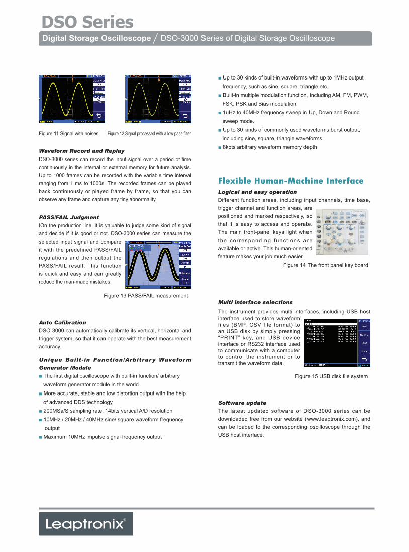
Waveform Record and Replay
DSO-3000 series can record the input signal over a period of time continuously in the internal or external memory for future analysis. Up to 1000 frames can be recorded with the variable time interval ranging from 1 ms to 1000s. The recorded frames can be played back continuously or played frame by frame, so that you can observe any frame and capture any tiny abnormality.
PASS/FAIL Judgment
IOn the production line, it is valuable to judge some kind of signal and decide if it is good or not. DSO-3000 series can measure the selected input signal and compare it with the predefined PASS/FAIL regulations and then output the PASS/FAIL result. This function is quick and easy and can greatly reduce the man-made mistakes.
Flexible Human-Machine InterfaceLogical and easy operation
Different function areas, including input channels, time base, trigger channel and function areas, are positioned and marked respectively, so that it is easy to access and operate. The main front-panel keys light when the corresponding funct ions are available or active. This human-oriented feature makes your job much easier.
Auto Calibration
DSO-3000 can automatically calibrate its vertical, horizontal and trigger system, so that it can operate with the best measurement accuracy.
Unique Built-in Function/Arbitrary Waveform
Generator Module
■ The first digital oscilloscope with built-in function/ arbitrarywaveform generator module in the world
■ More accurate, stable and low distortion output with the helpof advanced DDS technology
■ 200MSa/S sampling rate, 14bits vertical A/D resolution■ 10MHz / 20MHz / 40MHz sine/ square waveform frequency
output■ Maximum 10MHz impulse signal frequency output
Multi interface selections
The instrument provides multi interfaces, including USB host interface used to store waveform files (BMP, CSV file format) to an USB disk by simply pressing “PRINT” key, and USB device interface or RS232 interface used to communicate with a computer to control the instrument or to transmit the waveform data.
Software update
The latest updated software of DSO-3000 series can be downloaded free from our website (www.leaptronix.com), and can be loaded to the corresponding oscilloscope through the USB host interface.
■ Up to 30 kinds of built-in waveforms with up to 1MHz outputfrequency, such as sine, square, triangle etc.
■ Built-in multiple modulation function, including AM, FM, PWM,FSK, PSK and Bias modulation.
■ 1uHz to 40MHz frequency sweep in Up, Down and Roundsweep mode.
■ Up to 30 kinds of commonly used waveforms burst output,including sine, square, triangle waveforms
■ 8kpts arbitrary waveform memory depth
Digital Storage Oscilloscope / DSO-3000 Series of Digital Storage Oscilloscope
Figure 11 Signal with noises Figure 12 Signal processed with a low pass filter
Figure 13 PASS/FAIL measurement
Figure 14 The front panel key board
Figure 15 USB disk file system
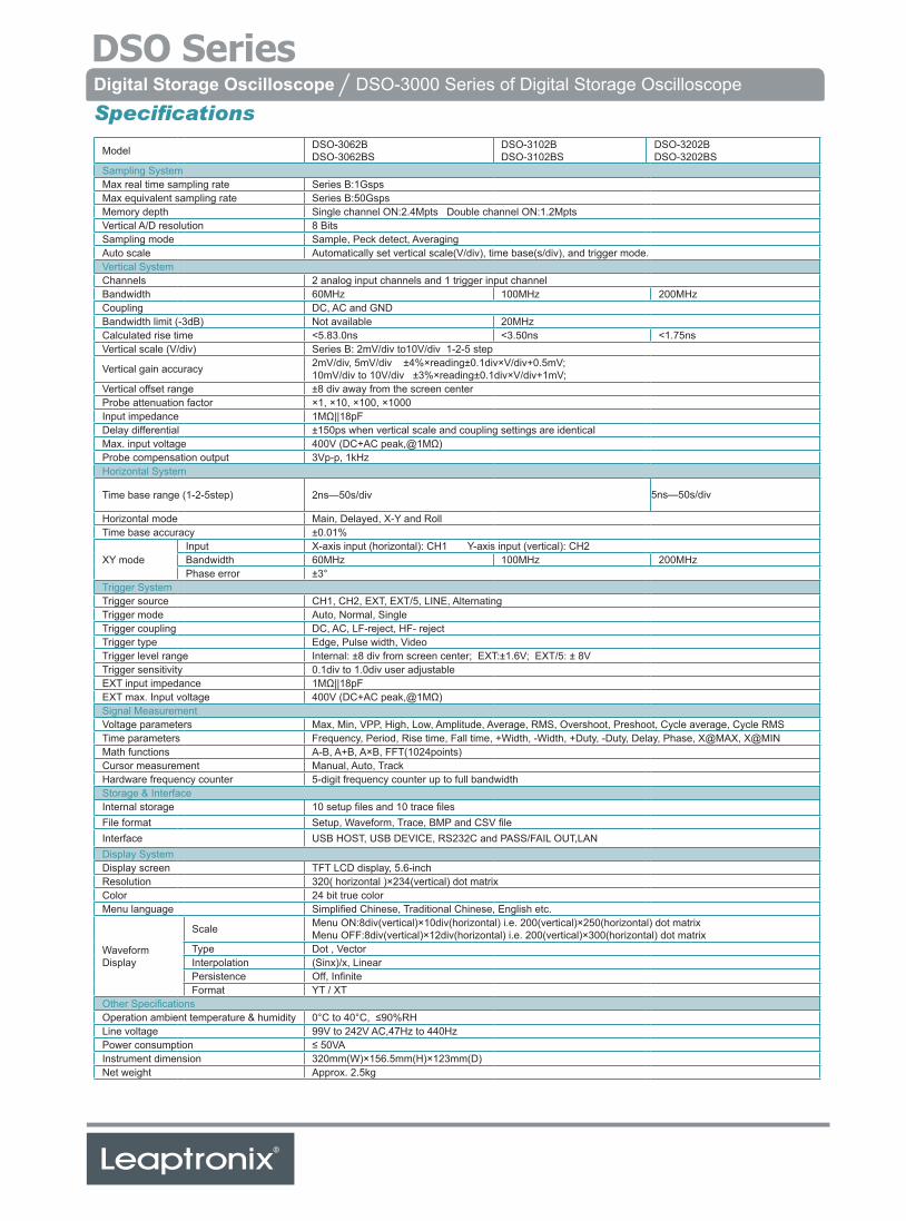
Digital Storage Oscilloscope / DSO-3000 Series of Digital Storage Oscilloscope
Specifications
Model DSO-3062BDSO-3062BS
DSO-3102BDSO-3102BS
DSO-3202BDSO-3202BS
Sampling SystemMax real time sampling rate Series B:1GspsMax equivalent sampling rate Series B:50GspsMemory depth Single channel ON:2.4Mpts Double channel ON:1.2MptsVertical A/D resolution 8 BitsSampling mode Sample, Peck detect, AveragingAuto scale Automatically set vertical scale(V/div), time base(s/div), and trigger mode.Vertical SystemChannels 2 analog input channels and 1 trigger input channelBandwidth 60MHz 100MHz 200MHzCoupling DC, AC and GNDBandwidth limit (-3dB) Not available 20MHzCalculated rise time <5.83.0ns <3.50ns <1.75nsVertical scale (V/div) Series B: 2mV/div to10V/div 1-2-5 step
Vertical gain accuracy 2mV/div, 5mV/div ±4%×reading±0.1div×V/div+0.5mV;10mV/div to 10V/div ±3%×reading±0.1div×V/div+1mV;
Vertical offset range ±8 div away from the screen centerProbe attenuation factor ×1, ×10, ×100, ×1000Input impedance 1MΩ||18pFDelay differential ±150ps when vertical scale and coupling settings are identicalMax. input voltage 400V (DC+AC peak,@1MΩ)Probe compensation output 3Vp-p, 1kHzHorizontal System
Time base range (1-2-5step) 2ns—50s/div 5ns—50s/div
Horizontal mode Main, Delayed, X-Y and RollTime base accuracy ±0.01%
XY modeInput X-axis input (horizontal): CH1 Y-axis input (vertical): CH2Bandwidth 60MHz 100MHz 200MHzPhase error ±3°
Trigger SystemTrigger source CH1, CH2, EXT, EXT/5, LINE, AlternatingTrigger mode Auto, Normal, SingleTrigger coupling DC, AC, LF-reject, HF- rejectTrigger type Edge, Pulse width, VideoTrigger level range Internal: ±8 div from screen center; EXT:±1.6V; EXT/5: ± 8VTrigger sensitivity 0.1div to 1.0div user adjustableEXT input impedance 1MΩ||18pFEXT max. Input voltage 400V (DC+AC peak,@1MΩ)Signal MeasurementVoltage parameters Max, Min, VPP, High, Low, Amplitude, Average, RMS, Overshoot, Preshoot, Cycle average, Cycle RMSTime parameters Frequency, Period, Rise time, Fall time, +Width, -Width, +Duty, -Duty, Delay, Phase, X@MAX, X@MINMath functions A-B, A+B, A×B, FFT(1024points)Cursor measurement Manual, Auto, TrackHardware frequency counter 5-digit frequency counter up to full bandwidthStorage & InterfaceInternal storage 10 setup files and 10 trace filesFile format Setup, Waveform, Trace, BMP and CSV fileInterface USB HOST, USB DEVICE, RS232C and PASS/FAIL OUT,LANDisplay SystemDisplay screen TFT LCD display, 5.6-inchResolution 320( horizontal )×234(vertical) dot matrixColor 24 bit true colorMenu language Simplified Chinese, Traditional Chinese, English etc.
Waveform Display
Scale Menu ON:8div(vertical)×10div(horizontal) i.e. 200(vertical)×250(horizontal) dot matrixMenu OFF:8div(vertical)×12div(horizontal) i.e. 200(vertical)×300(horizontal) dot matrix
Type Dot , VectorInterpolation (Sinx)/x, LinearPersistence Off, InfiniteFormat YT / XT
Other SpecificationsOperation ambient temperature & humidity 0°C to 40°C, ≤90%RHLine voltage 99V to 242V AC,47Hz to 440HzPower consumption ≤ 50VAInstrument dimension 320mm(W)×156.5mm(H)×123mm(D)Net weight Approx. 2.5kg
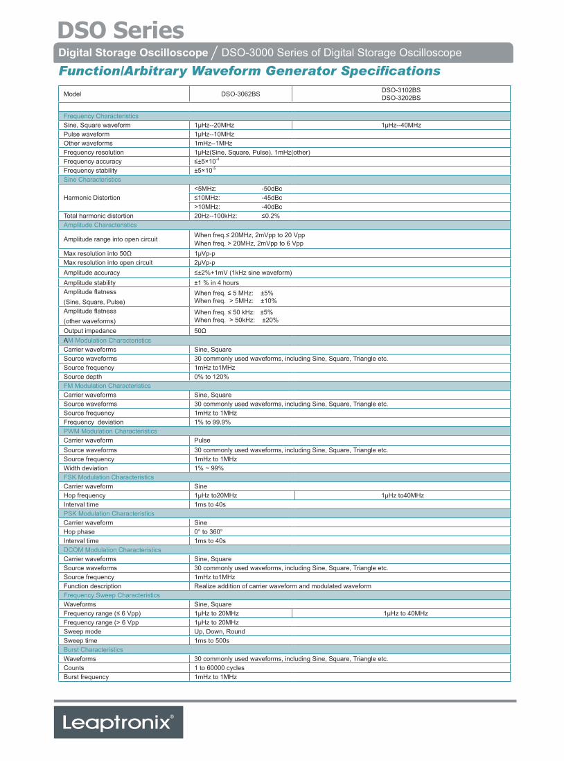
Digital Storage Oscilloscope / DSO-3000 Series of Digital Storage Oscilloscope
Function/Arbitrary Waveform Generator Specifications
Model DSO-3062BS DSO-3102BSDSO-3202BS
Frequency CharacteristicsSine, Square waveform 1μHz--20MHz 1μHz--40MHzPulse waveform 1μHz--10MHzOther waveforms 1mHz--1MHzFrequency resolution 1μHz(Sine, Square, Pulse), 1mHz(other)Frequency accuracy ≤±5×10⁻⁴ Frequency stability ±5×10⁻⁵
Sine Characteristics
Harmonic Distortion<5MHz: -50dBc≤10MHz: -45dBc>10MHz: -40dBc
Total harmonic distortion 20Hz--100kHz: ≤0.2%Amplitude Characteristics
Amplitude range into open circuit When freq.≤ 20MHz, 2mVpp to 20 VppWhen freq. > 20MHz, 2mVpp to 6 Vpp
Max resolution into 50Ω 1μVp-pMax resolution into open circuit 2μVp-pAmplitude accuracy ≤±2%+1mV (1kHz sine waveform)Amplitude stability ±1 % in 4 hoursAmplitude flatness(Sine, Square, Pulse)
When freq. ≤ 5 MHz: ±5% When freq. > 5MHz: ±10%
Amplitude flatness(other waveforms)
When freq. ≤ 50 kHz: ±5% When freq. > 50kHz: ±20%
Output impedance 50ΩAM Modulation CharacteristicsCarrier waveforms Sine, SquareSource waveforms 30 commonly used waveforms, including Sine, Square, Triangle etc.Source frequency 1mHz to1MHzSource depth 0% to 120%FM Modulation CharacteristicsCarrier waveforms Sine, SquareSource waveforms 30 commonly used waveforms, including Sine, Square, Triangle etc.Source frequency 1mHz to 1MHzFrequency deviation 1% to 99.9%PWM Modulation CharacteristicsCarrier waveform PulseSource waveforms 30 commonly used waveforms, including Sine, Square, Triangle etc.Source frequency 1mHz to 1MHzWidth deviation 1% ~ 99%FSK Modulation CharacteristicsCarrier waveform Sine Hop frequency 1μHz to20MHz 1μHz to40MHzInterval time 1ms to 40s PSK Modulation CharacteristicsCarrier waveform Sine Hop phase 0° to 360°Interval time 1ms to 40sDCOM Modulation CharacteristicsCarrier waveforms Sine, SquareSource waveforms 30 commonly used waveforms, including Sine, Square, Triangle etc.Source frequency 1mHz to1MHz Function description Realize addition of carrier waveform and modulated waveformFrequency Sweep CharacteristicsWaveforms Sine, SquareFrequency range (≤ 6 Vpp) 1μHz to 20MHz 1μHz to 40MHzFrequency range (> 6 Vpp 1μHz to 20MHzSweep mode Up, Down, RoundSweep time 1ms to 500sBurst CharacteristicsWaveforms 30 commonly used waveforms, including Sine, Square, Triangle etc.Counts 1 to 60000 cyclesBurst frequency 1mHz to 1MHz
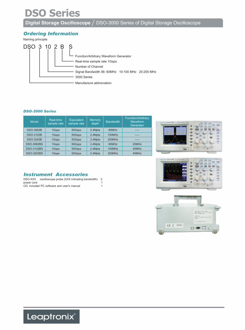
Digital Storage Oscilloscope / DSO-3000 Series of Digital Storage Oscilloscope
Instrument AccessoriesDSO-XXX oscilloscope probe (XXX indicating bandwidth) 2power cord 1CD, included PC software and user's manual 1
Ordering InformationNaming principle:
DSO 3 10 2 B SFunction/Arbitrary Waveform GeneratorReal-time sample rate 1GspsNumber of ChannelSignal Bandwidth 06: 60MHz 10:100 MHz 20:200 MHz3000 Series
Manufacture abbreviation
Model Real-time sample rate
Equivalent sample rate
Memory depth Bandwidth
Function/ArbitraryWaveformGenerator
DSO-3062B 1Gsps 50Gsps 2.4Mpts 60MHz -----
DSO-3102B 1Gsps 50Gsps 2.4Mpts 100MHz -----DSO-3202B 1Gsps 50Gsps 2.4Mpts 200MHz -----
DSO-3062BS 1Gsps 50Gsps 2.4Mpts 60MHz 20MHzDSO-3102BS 1Gsps 50Gsps 2.4Mpts 100MHz 40MHzDSO-3202BS 1Gsps 50Gsps 2.4Mpts 200MHz 40MHz
DSO-3000 Series
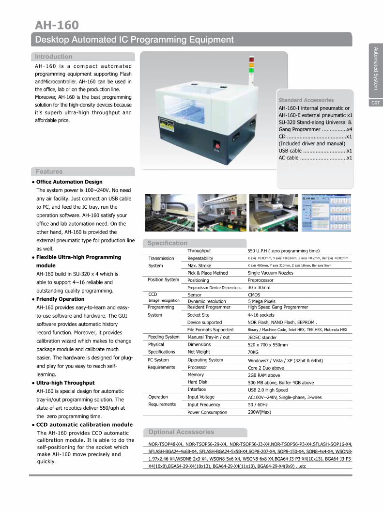
Automated System
NOR-TSOP48-X4, NOR-TSOP56-29-X4, NOR-TSOP56-J3-X4,NOR-TSOP56-P3-X4,SFLASH-SOP16-X4,
SFLASH-BGA24-4x6B-X4, SFLASH-BGA24-5x5B-X4,SOP8-207-X4, SOP8-150-X4, SON8-4x4-X4, WSON8-
1.97x2.46-X4,WSON8-2x3-X4, WSON8-5x6-X4, WSON8-6x8-X4,BGA64-J3-P3-X4(10x13), BGA64-J3-P3-
X4(10x8),BGA64-29-X4(10x13), BGA64-29-X4(11x13), BGA64-29-X4(9x9) ...etc
Transmission
System
Repeatability
Max. Stroke
Pick & Place Method
Positioning
Preprocissor Device Dimensions
X axis ±0.03mm, Y axis ±0.03mm, Z axis ±0.2mm, Bar axis ±0.01mm
X axis 400mm, Y axis 310mm, Z axis 18mm, Bar axis 5mm
Single Vacuum Nozzles
Preprocessor
30 x 30mm
Position System
Programming
System
Feeding System
PC System
Requirements
Operation
Requirements
Operating System
Processor
Memory
Hard Disk
Interface
Input Voltage
Input Frequency
Power Consumption
Windows7 / Vista / XP (32bit & 64bit)
Core 2 Duo above
2GB RAM above
500 MB above, Buffer 4GB above
USB 2.0 High Speed
AC100V~240V, Single-phase, 3-wires
50 / 60Hz
200W(Max)
Physical
Specifications
Manural Tray-in / out
Dimensions
Net Weight
JEDEC stander
520 x 700 x 550mm
70KG
550 U.P.H ( zero programming time)Throughput
Resident Programmer
Socket Site
Device supported
File Formats Supported
High Speed Gang Programmer
4~16 sockets
NOR Flash, NAND Flash, EEPROM .
Binary / Machine Code, Intel HEX, TEK HEX, Motorola HEX
● Office Automation Design
The system power is 100~240V. No need
any air facility. Just connect an USB cable
to PC, and feed the IC tray, run the
operation software. AH-160 satisfy your
office and lab automation need. On the
other hand, AH-160 is provided the
external pneumatic type for production line
as well.
● Flexible Ultra-high Programming
module
AH-160 build in SU-320 x 4 which is
able to support 4~16 reliable and
outstanding quality programming.
● Friendly Operation
AH-160 provides easy-to-learn and easy-
to-use software and hardware. The GUI
software provides automatic history
record function. Moreover, it provides
calibration wizard which makes to change
package module and calibrate much
easier. The hardware is designed for plug-
and play for you easy to reach self-
learning.
● Ultra-high Throughput
AH-160 is special design for automatic
tray-in/out programming solution. The
state-of-art robotics deliver 550/uph at
the zero programming time.
● CCD automatic calibration module
The AH-160 provides CCD automaticcalibration module. It is able to do theself-positioning for the socket whichmake AH-160 move precisely andquickly.
AH -160 i s a c ompac t au t oma t ed programming equipment supporting Flash andMicrocontroller. AH-160 can be used in the office, lab or on the production line.Moreover, AH-160 is the best programming solution for the high-density devices because it's superb ultra-high throughput and affordable price.
Features
Introduction
Optional Accessories
Specification
Standard AccessoriesAH-160-I internal pneumatic or AH-160-E external pneumatic x1SU-320 Stand-along Universal & Gang Programmer ................x4CD ......................................x1(Included driver and manual) USB cable ............................x1AC cable ..............................x1
C18
Desktop Automated IC Programming EquipmentAH-160
C07
SensorDynamic resolution
CMOS5 Mega Pixels
CCD Image recognition
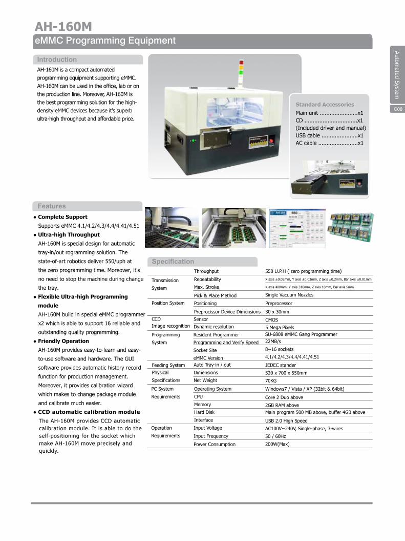
Automated System
C17Standard AccessoriesMain unit .......................x1CD ................................x1(Included driver and manual) USB cable ......................x1AC cable ........................x1
● Complete Support
Supports eMMC 4.1/4.2/4.3/4.4/4.41/4.51
● Ultra-high Throughput
AH-160M is special design for automatic
tray-in/out rogramming solution. The
state-of-art robotics deliver 550/uph at
the zero programming time. Moreover, it's
no need to stop the machine during change
the tray.
● Flexible Ultra-high Programming
module
AH-160M build in special eMMC programmer
x2 which is able to support 16 reliable and
outstanding quality programming.
● Friendly Operation
AH-160M provides easy-to-learn and easy-
to-use software and hardware. The GUI
software provides automatic history record
function for production management.
Moreover, it provides calibration wizard
which makes to change package module
and calibrate much easier.
● CCD automatic calibration module
The AH-160M provides CCD automaticcalibration module. It is able to do theself-positioning for the socket whichmake AH-160M move precisely andquickly.
AH-160M is a compact automated programming equipment supporting eMMC.AH-160M can be used in the office, lab or on the production line. Moreover, AH-160M is the best programming solution for the high-density eMMC devices because it's superb ultra-high throughput and affordable price.
Features
Introduction
Specification
Transmission
System
Repeatability
Max. Stroke
Pick & Place Method
Positioning
Preprocissor Device Dimensions
X axis ±0.03mm, Y axis ±0.03mm, Z axis ±0.2mm, Bar axis ±0.01mm
X axis 400mm, Y axis 310mm, Z axis 18mm, Bar axis 5mm
Single Vacuum Nozzles
Preprocessor
30 x 30mm
Position System
Programming
System
Feeding System
PC System
Requirements
Operation
Requirements
Operating System
CPU
Memory
Hard Disk
Interface
Input Voltage
Input Frequency
Power Consumption
Windows7 / Vista / XP (32bit & 64bit)
Core 2 Duo above
2GB RAM aboveMain program 500 MB above, buffer 4GB above
USB 2.0 High Speed
AC100V~240V, Single-phase, 3-wires
50 / 60Hz
200W(Max)
Physical
Specifications
Auto Tray-in / out
Dimensions
Net Weight
JEDEC stander
520 x 700 x 550mm
70KG
550 U.P.H ( zero programming time)Throughput
Resident Programmer
Programming and Verify Speed
Socket Site
eMMC Version
SU-6808 eMMC Gang Programmer22MB/s
8~16 sockets
4.1/4.2/4.3/4.4/4.41/4.51
eMMC Programming EquipmentAH-160M
C22
Sensor
Dynamic resolutionCMOS
5 Mega Pixels
CCD Image recognition
C22 C08
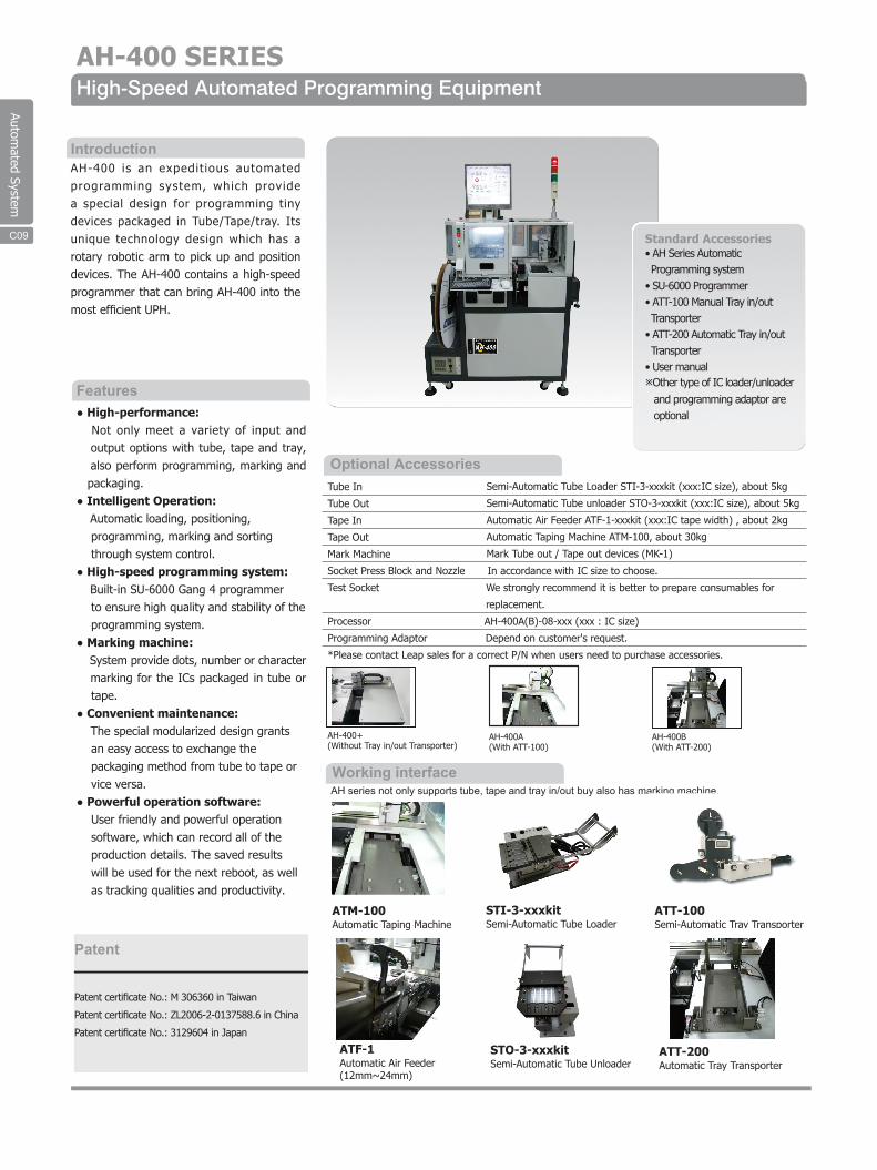
Automated System
AH series not only supports tube, tape and tray in/out buy also has marking machine.
ATT-200ATF-1 ATT-200
ATM-100 ATT-100
Automatic Air Feeder (12mm~24mm)
Automatic Tray Transporter
Automatic Taping Machine
STO-3-xxxkit
STI-3-xxxkit
Semi-Automatic Tube Unloader
Semi-Automatic Tube Loader Semi-Automatic Tray Transporter
ATF-1
AH-400 SERIESHigh-Speed Automated Programming Equipment
IntroductionAH-400 is an expedit ious automated programming system, which provide a special design for programming tiny devices packaged in Tube/Tape/tray. Its unique technology design which has a rotary robotic arm to pick up and position devices. The AH-400 contains a high-speed programmer that can bring AH-400 into the most efficient UPH.
● High-performance: Not only meet a variety of input and output options with tube, tape and tray,
also perform programming, marking and packaging.● Intelligent Operation꞉
Automatic loading, positioning,programming, marking and sortingthrough system control.
● High-speed programming system:Built-in SU-6000 Gang 4 programmerto ensure high quality and stability of theprogramming system.
● Marking machine꞉System provide dots, number or charactermarking for the ICs packaged in tube ortape.
● Convenient maintenance꞉The special modularized design grantsan easy access to exchange thepackaging method from tube to tape orvice versa.
● Powerful operation software꞉User friendly and powerful operationsoftware, which can record all of theproduction details. The saved resultswill be used for the next reboot, as wellas tracking qualities and productivity.
Features
Standard Accessories• AH Series Automatic Programming system• SU-6000 Programmer• ATT-100 Manual Tray in/out Transporter• ATT-200 Automatic Tray in/out Transporter• User manualOther type of IC loader/unloader and programming adaptor are optional
Optional AccessoriesTube In
Tube Out
Tape In
Tape Out
Mark Machine
Socket Press Block and Nozzle In accordance with IC size to choose.
Test Socket We strongly recommend it is better to prepare consumables for
replacement.
Processor AH-400A(B)-08-xxx (xxx : IC size)
Programming Adaptor Depend on customer's request.
*Please contact Leap sales for a correct P/N when users need to purchase accessories.
Semi-Automatic Tube Loader STI-3-xxxkit (xxx:IC size), about 5kg
Semi-Automatic Tube unloader STO-3-xxxkit (xxx:IC size), about 5kg
Automatic Air Feeder ATF-1-xxxkit (xxx:IC tape width) , about 2kg
Automatic Taping Machine ATM-100, about 30kg
Mark Tube out / Tape out devices (MK-1)
C09
AH-400+ (Without Tray in/out Transporter)
AH-400A (With ATT-100)
AH-400B (With ATT-200)
Patent
Patent certificate No.: M 306360 in Taiwan
Patent certificate No.: ZL2006-2-0137588.6 in China
Patent certificate No.: 3129604 in Japan
Working interface
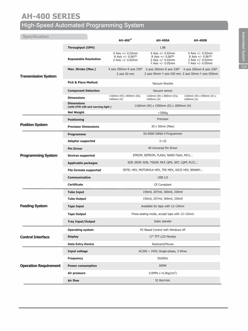
Automated System
AH-400 SERIESHigh-Speed Automated Programming System
Transmission System
Position System
Programming System
Feeding System
Control Interface
Operation Requirement
Throughput (UPH)
Repeatable Resolution
Max. Stroke (Max.)
Pick & Place Method
Component Detection
Dimensions
Dimensions(with ATM-100 and warning light )
Net Weight
Positioning
Precissor Dimensions
Programmer
Adapter supported
Pin Driver
Devices supported
Applicable packages
File formats supported
Communication
Certificate
Tube Input
Tube Output
Tape Input
Tape Output
Tray Input/Output
Operating system
Display
Data Entry Device
Input voltage
Frequency
Power consumption
Air pressure
Air flow
AH-400+
X Axis +/- 0.02mmR Axis +/- 0.067ºZ Axis +/- 0.02mm
1160mm (W) x 800mm (D)x1400mm (H)
X axis 350mm R axis 330º
Z axis 50 mm
AH-400A
1.8K
1160mm (W) x 800mm (D)x1400mm (H)
Z axis 50mm Y axis 550 mm
Vacuum Nozzles
Vacuum sensor
1160mm (W) x 1500mm (D) x 1800mm (H)
~300kg
Precissor
30 x 30mm (Max)
SU-6000 GANG-4 Programmer
2~16
40 Universal Pin Driver
EPROM, EEPROM, FLASH, NAND Flash, MCU...
SOP, SSOP, SON, TSSOP, MLP, QFN, SNT, LQFP, PLCC...
INTEL HEX, MOTOROLA HEX, TEK MEX, ASCII HEX, BINARY...
USB 2.0
CE Compliant
150mil, 207mil, 300mil, 330mil
150mil, 207mil, 300mil, 330mil
Available for tape with 12~24mm
Press-sealing mode, accept tape with 12~32mm
Jedec stander
PC-Based Control with Windows XP
17" TFT LCD Monitor
Keyboard/Mouse
AC200 ~ 245V, Single-phase, 3 Wires
50/60Hz
600W
0.6MPa (~6.0kg/cm2)
32 liter/min.
X axis 350mm R axis 330º
X Axis +/- 0.02mmR Axis +/- 0.067ºZ Axis +/- 0.02mmY Axis +/- 0.05mm
1160mm (W) x 950mm (D) x1400mm (H)
Z axis 50mm Y axis 550mmX axis 350mm R axis 330º
X Axis +/- 0.02mmR Axis +/- 0.067ºZ Axis +/- 0.02mmY Axis +/- 0.05mm
AH-400B
C18 C09
Specification
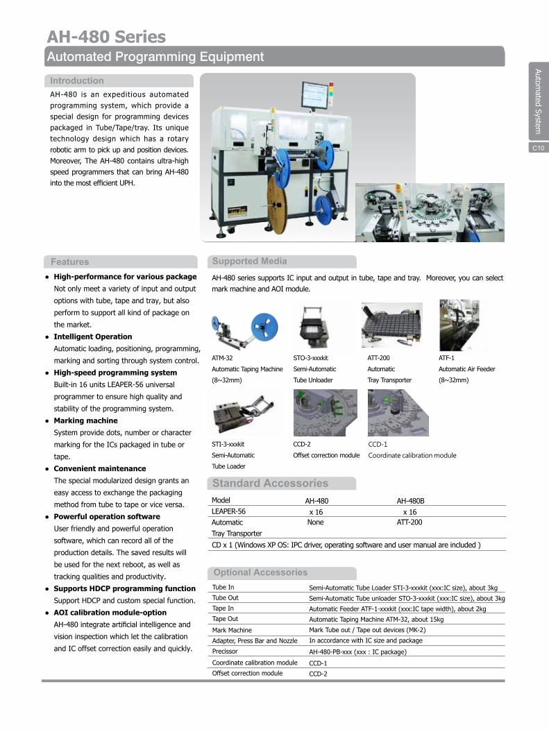
Automated System
Tube In
Tube Out
Tape In
Tape Out
Mark Machine
Adapter, Press Bar and Nozzle
Precissor
Coordinate calibration module
Offset correction module
Semi-Automatic Tube Loader STI-3-xxxkit (xxx:IC size), about 3kg
Semi-Automatic Tube unloader STO-3-xxxkit (xxx:IC size), about 3kg
Automatic Feeder ATF-1-xxxkit (xxx:IC tape width), about 2kg
Automatic Taping Machine ATM-32, about 15kg
Mark Tube out / Tape out devices (MK-2)
In accordance with IC size and package
AH-480-PB-xxx (xxx : IC package)
CCD-1
CCD-2
● High-performance for various package
Not only meet a variety of input and output
options with tube, tape and tray, but also
perform to support all kind of package on
the market.
● Intelligent Operation
Automatic loading, positioning, programming,
marking and sorting through system control.
● High-speed programming system
Built-in 16 units LEAPER-56 universal
programmer to ensure high quality and
stability of the programming system.
● Marking machine
System provide dots, number or character
marking for the ICs packaged in tube or
tape.
● Convenient maintenance
The special modularized design grants an
easy access to exchange the packaging
method from tube to tape or vice versa.
● Powerful operation software
User friendly and powerful operation
software, which can record all of the
production details. The saved results will
be used for the next reboot, as well as
tracking qualities and productivity.
● Supports HDCP programming function
Support HDCP and custom special function.
● AOI calibration module-option
AH-480 integrate artificial intelligence and
vision inspection which let the calibration
and IC offset correction easily and quickly.
AH-480 is an expeditious automated programming system, which provide a special design for programming devices packaged in Tube/Tape/tray. Its unique technology design which has a rotary robotic arm to pick up and position devices. Moreover, The AH-480 contains ultra-high speed programmers that can bring AH-480 into the most efficient UPH.
Features
Introduction
Automated Programming Equipment
Optional Accessories
Supported Media
AH-480 series supports IC input and output in tube, tape and tray. Moreover, you can select mark machine and AOI module.
AH-480 Series
C14
Standard AccessoriesAH-480 x 16 None
AH-480B x 16
ATT-200
CD x 1 (Windows XP OS: IPC driver, operating software and user manual are included )
ModelLEAPER-56Automatic Tray Transporter
C10
ATM-32
Automatic Taping Machine
(8~32mm)
STO-3-xxxkit
Semi-Automatic
Tube Unloader
ATT-200
Automatic
Tray Transporter
ATF-1
Automatic Air Feeder
(8~32mm)
STI-3-xxxkit
Semi-Automatic
Tube Loader
CCD-2
Offset correction module
CCD-1
Coordinate calibration module
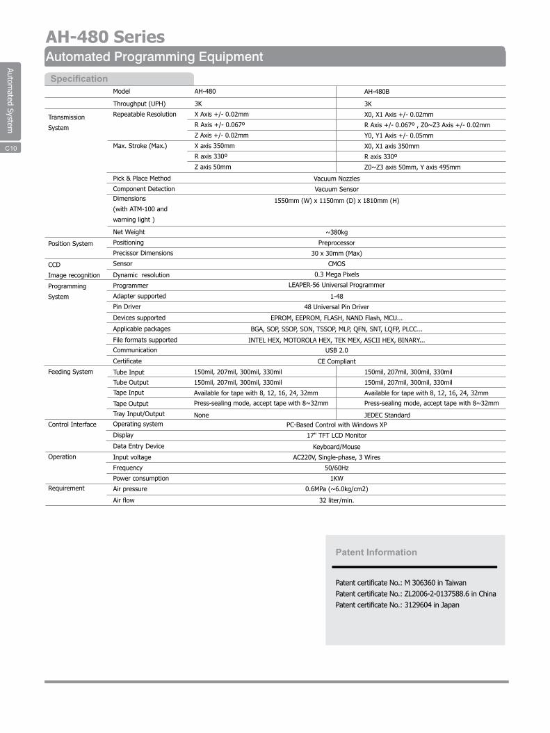
Automated System
Transmission
System
Position System
CCD
Image recognition
Programming
System
Feeding System
Control Interface
Operation
Requirement
AH-480
3K
X Axis +/- 0.02mm
R Axis +/- 0.067º
Z Axis +/- 0.02mm
X axis 350mm
R axis 330º
Z axis 50mm
AH-480B
3K
X0, X1 Axis +/- 0.02mm
R Axis +/- 0.067º , Z0~Z3 Axis +/- 0.02mm
Y0, Y1 Axis +/- 0.05mm
X0, X1 axis 350mm
R axis 330º
Z0~Z3 axis 50mm, Y axis 495mm
Model
Throughput (UPH)
Repeatable Resolution
Max. Stroke (Max.)
Pick & Place Method
Component DetectionDimensions
(with ATM-100 and
warning light )
Net Weight
Positioning
Precissor Dimensions
Sensor
Dynamic resolution
Programmer
Adapter supported
Pin Driver
Devices supported
Applicable packages
File formats supported
Communication
Certificate
Tube Input
Tube Output
Tape Input
Tape Output
Tray Input/Output
Operating system
Display
Data Entry Device
Input voltage
Frequency
Power consumption
Air pressure
Air flow
Vacuum Nozzles
Vacuum Sensor
1550mm (W) x 1150mm (D) x 1810mm (H)
~380kg
Preprocessor
30 x 30mm (Max)
CMOS
0.3 Mega Pixels
LEAPER-56 Universal Programmer
1-48
48 Universal Pin Driver
EPROM, EEPROM, FLASH, NAND Flash, MCU...
BGA, SOP, SSOP, SON, TSSOP, MLP, QFN, SNT, LQFP, PLCC...
INTEL HEX, MOTOROLA HEX, TEK MEX, ASCII HEX, BINARY...
USB 2.0
CE Compliant
Specification
Patent Information
Patent certificate No.: M 306360 in TaiwanPatent certificate No.: ZL2006-2-0137588.6 in ChinaPatent certificate No.: 3129604 in Japan
C15
Automated Programming EquipmentAH-480 Series
150mil, 207mil, 300mil, 330mil
150mil, 207mil, 300mil, 330mil
Available for tape with 8, 12, 16, 24, 32mm
Press-sealing mode, accept tape with 8~32mm
NonePC-Based Control with Windows XP
17" TFT LCD Monitor
Keyboard/Mouse
AC220V, Single-phase, 3 Wires
50/60Hz
1KW
0.6MPa (~6.0kg/cm2)
32 liter/min.
150mil, 207mil, 300mil, 330mil
150mil, 207mil, 300mil, 330mil
Available for tape with 8, 12, 16, 24, 32mm
Press-sealing mode, accept tape with 8~32mm
JEDEC Standard
C10
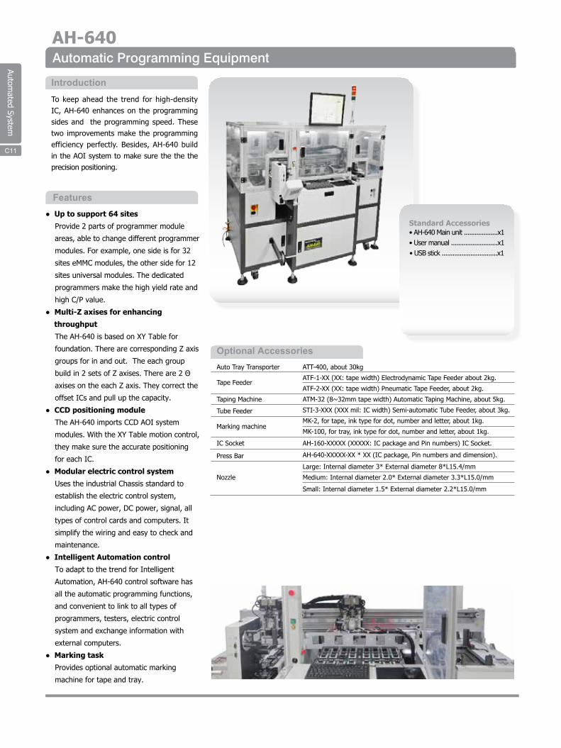
Automated System
● Up to support 64 sites
Provide 2 parts of programmer module
areas, able to change different programmer
modules. For example, one side is for 32
sites eMMC modules, the other side for 12
sites universal modules. The dedicated
programmers make the high yield rate and
high C/P value.
● Multi-Z axises for enhancing
throughput
The AH-640 is based on XY Table for
foundation. There are corresponding Z axis
groups for in and out. The each group
build in 2 sets of Z axises. There are 2 Θ
axises on the each Z axis. They correct the
offset ICs and pull up the capacity.
● CCD positioning module
The AH-640 imports CCD AOI system
modules. With the XY Table motion control,
they make sure the accurate positioning
for each IC.
● Modular electric control system
Uses the industrial Chassis standard to
establish the electric control system,
including AC power, DC power, signal, all
types of control cards and computers. It
simplify the wiring and easy to check and
maintenance.
● Intelligent Automation control
To adapt to the trend for Intelligent
Automation, AH-640 control software has
all the automatic programming functions,
and convenient to link to all types of
programmers, testers, electric control
system and exchange information with
external computers.
● Marking task
Provides optional automatic marking
machine for tape and tray.
To keep ahead the trend for high-density IC, AH-640 enhances on the programming sides and the programming speed. These two improvements make the programming efficiency perfectly. Besides, AH-640 build in the AOI system to make sure the the the precision positioning.
Features
Introduction
Automatic Programming EquipmentAH-640
Standard Accessories• AH-640 Main unit ...................x1 • User manual ..........................x1• USB stick ...............................x1
Auto Tray Transporter
Tape Feeder
Taping Machine
Tube Feeder
Marking machine
IC Socket
Press Bar
Nozzle
ATT-400, about 30kg
ATF-1-XX (XX: tape width) Electrodynamic Tape Feeder about 2kg.
ATF-2-XX (XX: tape width) Pneumatic Tape Feeder, about 2kg.
ATM-32 (8~32mm tape width) Automatic Taping Machine, about 5kg.
STI-3-XXX (XXX mil: IC width) Semi-automatic Tube Feeder, about 3kg.
MK-2, for tape, ink type for dot, number and letter, about 1kg.
MK-100, for tray, ink type for dot, number and letter, about 1kg.
AH-160-XXXXX (XXXXX: IC package and Pin numbers) IC Socket.
AH-640-XXXXX-XX * XX (IC package, Pin numbers and dimension).
Large: Internal diameter 3* External diameter 8*L15.4/mm
Medium: Internal diameter 2.0* External diameter 3.3*L15.0/mm
Small: Internal diameter 1.5* External diameter 2.2*L15.0/mm
Optional Accessories
C11
Automated System
Handler System
Motion System
AOI System
Programmer
Loader & Unloader
Control System
Power System
Air System
Specification
U.P.H.
Placement repeatability
Pick and place method
Dimensions
Net weight
X axis stroke
Y axis stroke
Z axis stroke
Θaxis stroke
Fixed CCD
Carried CCD
Resident programmer
Programming Site
Tray input
Tray output
Tape input
Tape output
Tube input
Operating system
Display
Data entry
Input voltage
Input frequency
Power consumptionAir pressure
Air flow
1500 (no programming time)
±0.03mm
4 vacuum nozzles
1655mm(W)*1520mm(H)*1060mm(D) [Without tower light]
1655mm(W)*2030mm(H)*1060mm(D) [With tower light]
600kg
1000mm
410mm
70mm
360°
Field of view: 25x20mm
Resolution: 0.02 mm
Repeatability: ±0.008 mm
Field of view: 35x25mm
Resolution: 0.045mm
Repeatability: ±0.03 mm
eMMC Gang Programmer
1 to 8 site, 1 to 8 socket per site, up to 64 socket.
Auto tray move in,stack up to 10 trays for JEDEC stander.
Auto tray move out,stack up to 10 trays for JEDEC stander.
Available for tape with 8mm, 12mm, 16mm, 24mm tape width.
Press-sealing mode,Accept tape with 8mm to 32mm tape width.
Support 150mil,207mil,300mil package.
PC base control with Windows XP Embedded
TFT LCD Monitor
Keyboard and mouse
AC 220~245V
50/60Hz
1.0KVA0.6MPa(5.5~6.0Kg/cm2)
50liter/min
C11
Automated System
Control System Operating system
Display
Data entry
Input voltage
Input line frequency
Power consumption
Size
Weight
PC-based control with Windows XP
17" TFT LCD monitor
keyboard/mouse
AC200 ~ 245V, Single-phase, 3-wires
50/60Hz
450W
800 x 950 x 1312 mm (W/D/H)
300Kg
Automated Package Changer - Taping Machine
● Automated tray-in
Stack up to 10 tray with JEDEC standard
for waiting and empty tray area.
Automated push in the waiting area for
robot pick movement. Automated pull for
the empty tray and keep them in the area.
Auto-detect and alarm system to inform
waiting and empty tray area situation.
Use the Step motor to drive the timing
belt which make the ball screw is able to
exactly transfer the system movement
procedure.
● Robot
Horizontal line movement adopts Servo
motor close loop control mode, precisely
and speedily. Vertical line movement
adopts Fuzzy control mode,will not
damage the devices. SMT level nozzle,
long life time and reliable.
● Tape and reel taping machine
Supports 8~58mm adjustable tape width.
Automated detect if the carrier tape on the
wrong position. Automated detect and
alarm for jam and empty package.
Provide convenient and easy operation
user interface.
APC-100 is a transferring system which can be used for transfering device in/out from tray, tube and Reel. It uses industry computer which makes all of the movement precisely and speedily. You can add the AOI module as well.
Features
Introduction
Specification
C12C22
Operation Requirement
Specification
Optional AccessoriesTube In: Semi-Automatic Tube Loader STI-3-xxxkit (xxx:IC size), 3kg
Tube Out: Semi-Automatic Tube unloader STO-3-xxxkit (xxx:IC size), 3kg
Tape In: Automatic Feeder ATF-1-xxxkit (xxx:IC tape width) , 2kg
Tape Out: Automatic Taping Machine ATM-32 / 58, 15kg
AOI Module
Mark Machine: Mark Tape out devices (MK-1)
Nozzle: In accordance with IC size
Pick and Place
Taping MachineTube in
Tray in/out
APC-100
Automated System
Power
Dimension
Net weight
Adjustable tape width
Carrier tape movement
Compressed air
Counter
Seal speed
Seal pressure
Seal type
Trailer/leader
Communication
Inspection
120/230VAC, 50/60Hz, 0.2kVa
860x 364x 190mm (without arm)
1347x 429 x190mm (with arm 45 degree)
5kg
8 to 32mm
Multiple of 4mm
5kg/cm
LCD
140mm/sec max
450g
Constant-pressure self-adhesive seal
Programmable
RS-232, I/O
Out of Carrier, Out of Tape, Empty, Floating, Location Error
Standard AccessoriesATM-32 Main unit............x1CD.................................x1(Included driver and manual) AC power code...............x1D-sub cable ...................x1
● Adjustable track assembly for tape widths
from 8 to 32mm.
● User-friendly software assures ease of
setup and operation.
● Current operating parameters and count
are saved at power down and restored at
power up.
● Optional tape-out mark and optical
inspection available.
The microprocessor controlled sealer and step motor drive assure precise handling of all taping parameters. Several advance speeds are selectable to accommodate problem parts and to minimize part jumping.Flexible, easy to use, and advanced electronic characteristics make the ATM-32 a perfect chose for taping. It only take 10 second to adjust the tape width without any tool. Moreover, it's low cost and high performance make ATM-32 popular on manufacturers.
Features
Introduction
Automated Taping Machine
C13
Specification
C22
ATM-32
Standard Accessories◎ AIM-101 Main Unit x1
◎ USB 2.0 Cable x1
◎ SD Card With Software&Manual x1
◎ Pneumatic Tube x1
◎ AC Cable x1
◎ Paint Marker
Automation
6F, No.4, Ln 609, Sec 5, Chongxin Rd., Sanchong Dist, New Taipei City, 24159, Taiwan, ROCTEL 02-2999-1860 FAX 02-2999-0015E-mail: [email protected]
Multi-Tray FeedingSupporting up to 15 JEDEC trays pre-placed.
Processes All In OneIntegrating automated feeding, marking, and tray-piling.
Eco-FriendlyEquipped with easily replaceable paint markers in Gold/Silver. Sharpie™ industrial permanent paint-markers are used.
Quick SelectionSupporting 16 sets of configurations for immediate use.
User-Friendly Inter faceEquipped with modularized buttons for easy operation.
AIM-101 AIM-101 AIM-101 Automated Ink Marker is specially designed for colored-paint marking/dotting on ICs in tray packing, integrating automated feeding, marking/dotting, and tray-piling up to 15 trays with extremely high speed. It offers highest mobility & least space needed and can be applicable under all circumstances, saving labor costs and minimizing man-made unstability to the utmost.
AIM-101 Automated Ink Marker is specially designed for colored-paint marking/dotting on ICs in tray packing, integrating automated feeding, marking/dotting, and tray-piling up to 15 trays with extremely high speed. It offers highest mobility & least space needed and can be applicable under all circumstances, saving labor costs and minimizing man-made unstability to the utmost.
Specification
Maximizing Working Efficiency
Minimizing Space Needed
Saving Labor Costs
Best Solution To Device Marking
Features
Supporting 15 Trays Automatically Fed InA u t o m a t e d I n k M a r k e r
Securit y SystemEquiped with standard LED alarm & Emergency button.
Gold x1 Silver x1
Tray JEDEC
Speed 6800 pcs/h
Trays Pre-Placed 15
Operation RangeX Axis: 310mm Y Axis: 420mmZ Axis: 110mm
Marking Method Paint Marker
Input 110-220V, Single Phase-3Wire
Frequency 50-60Hz
Air Pressure 0.6 MPa (6.0KG/CM²)
Dimension & Weight 521x524x230mm, 20KG
Interface USB
Repeatability Precision ± 0.1mm
Automated System
C14
www.leap.com.tw 8 :lt TEL-02-2999-1860 FAX:02-2999·9874 tfi:ltl'!J:JllUl.llif&n~611124
..Cllt TEL-021· 5777-1796 FAX:021-5777-l 796 41838 ~ff'Nrul:OUnt~l!518~2441301 (..l:jlf•iilliHF3ttK~D:•~N:B)
:ll:lil TEL-Olo-62652592 FAX:Ol0.62655303 :il;J;(ifillllJl!tK1S1tllli33~615E
.,. TEL-0769--85349978 FAX.'0769-85349686 •wma~•a•~•~•a*•uF
www.leap.com.tw [email protected]
Tllpel TEL:O:Z.2999-1860 FAX.1>2·2999-9873 81'-4,No.4 , Ln.609, Sec.5, Chongxin Rd., S.nchong Di.t., New Taipei Olly 24159, Talwan, ROC
Shenghal TEL:021-5777· 1 798 FAX:021-5777-1798 #838 Songflang Dlalrict, Shenghal XJn Bride Road, Room 301, 518, No.24
eoq1ng TEL:O 10-82852592 FAX.'010-82655303 No. 815, Apartment, No. 33 5uztlou SL, Haldlan oi.trict, Beijing
Dongguan TEL:0789-85349978 FAX:0189-85349688 12F, Hua'lll'I Shangzhu Bufldlng, Changquing SL, CHang'en T-n. Dongguen
Leaptronix www.leaptronix.com ~:lt TEL-02· 2999· 3837 FAX:02-2999·7710 1ijl;m= • • •li1&nf6l609l!l8lt9ll:Z4
Taipei TEl.:02·2999-3837 FAX:02-2999-7710 9f-4,No.18, Ln.809, Soc.5, Chongldn Rd .. Sanchong Dist., Now TalpoJ Cl\Y 24159, TalWan, ROC
m n iili ii ::r II M Ii fH Ji BR ~ El U!I LEAP ELECTRONIC CO. LTD.
Copyright © 2016 LEAP ELECTRONIC CO., LTD. All Rights Reserved