Embed Size (px)
Citation preview

1
Installation, Operation & Application GuideFor more information on our complete range of American-made products, wiring diagrams, troubleshooting tips, and more, please visit us at www.icmcontrols.com
Auto ChangeoverProgrammable Thermostat
• 7-Day,5-2-Day,or5-1-1-DayProgrammable
• ConfigurableforMultipleSystems
• LargeDisplaywithBacklight
• SelectableFahrenheitorCelsius
• IconIndicatorLights
• RelayOutputs–MinimumVoltageDropinThermostat
• RemoteSensorCompatible
• IdeallySuitedfor:–Residential(NewConstruction/Replacement)–LightCommercial
• Workswithtwo-transformersystems
AUTOSCHEDULE
COOL
FAN
COOL
MODE
PMOFF
Wed

2
AUTOSCHEDULE
COOL
FAN
COOL
MODE
PMOFF
Wed
Thermostat Controls
Left Arrow (Go Back)
Right Arrow (Forward)
Down Arrow
Up Arrow
HomeMenu Mode (Heat/Cool) Fan Schedule
AUTOSCHEDULE
COOL
FAN
COOL
MODE
PMOFF
Wed
Package Contents/Tools RequiredPackageincludes: Thermostat,base,wiringlabels,screws,wallanchors,andInstallation, Operation and Application Guide.
Toolsrequiredforinstallation:Drillwith3/16”bit,hammer,screwdriver
SpecificationsElectricalRating:24VAC(18-30VAC),1ampmaximumperoutputterminal,5ampmaximumtotalload
TemperatureControlRange:45°Fto90°F(7°Cto32°C)Accuracy:±1°F(±0.5°C)
Anti-shortCycle:4minutes(bypassanti-shortcycledelaybyreturningtoOFFmodeandpressingthe icon).
BacklightOperations:15seconds
SystemConfigurations:Allmaybeusedwithheatpump,gas,oil,electric,andairconditioning
•I1010WR:1-stageheat,1-stagecool
•I2010WR:2-stageheat,1-stagecool
•I2020WR:2-stageheat,2-stagecool
•I3020WR:3-stageheat,2-stagecool

3
Mode of OperationThethermostatisaprogrammable,manualorautochangeover,upto3-stageheat(dependingonyourmodel)andupto2-stagecool(dependingonyourmodel)thermostat.Itfunctionswithairconditioning,heatpumps,gas,oil,orelectricheatsystems.Somethermostatsaredualfuelcompatibleandanoutdoorsensorcanbeusedtomonitortheambienttemperature.Asecondremotesensormaybeusedtomonitorthetemperatureinanotherarea.Thethermostatactivatestheheatingappliancewhentheroomtemperatureisbelowthesetheattemperature(bythedifferentialtemperature).Whenthecallforheathasbeensatisfied,theoutputsareturnedoff.Withheatpumps,thethermostatwillnotletthecompressorcomeonfor4minutesafteritturnsofftoprotectyourcompressor.
Whentheroomtemperatureisgreaterthanthesetcooltemperature(bythedifferentialtemperature),thecoolingdeviceisactivated.Whenthecallforcoolinghasbeensatisfied,theoutputsareturnedoff.Thethermostatwillnotletthecompressorcomeonfor4minutesafteritturnsofftoprotectyourcompressor.
Theprogramschedulecanbeoverriddenbychangingthesettemperature( or ).Thisputsthethermostatintoatemporaryhold.Itwillautomaticallyreturntotheprogramscheduleatthenextprogramscheduletransition.Toremovethe
temporaryholdbeforethenextscheduletransition,press icontwice.
ThethermostatisalsoWi-Ficompatible.Afteryouconnectyourthermostattoyourwirelessnetwork,youcanmonitorandcontrolyourthermostatusingtheapp(availableformostdevices)oracomputerconnectedtotheinternet.

4
UP–Usedtoincreasethetime,settemperatures,andtoadjustconfigurationsettings.
DOWN–Usedtodecreasethetime,settemperatures,andtoadjustconfigurationsettings.
MENU–Usedtoenterconfiguration,settheclock,lockthethermostat,orselectviewingoptions. CONFIG Setsupthermostattoworkforspecificsystems. CLOCK Setyear,month,date,andtime. WEATHER Showsthehighsandlowsforthreedays. LOCK Allowsyoutolockthethermostattopreventtampering. VIEW Allowsyoutoseeboththeremotesensortemperatures,date,currentscheduleperiod,lockscreen,filter
accumulatedtime,andshowdetails(systemstatus).FAN–UsedtoselectbetweenAUTO,ON,andHOURLYfanoperation.
MODE–UsedtoselectbetweenOFF,HEAT,EMERGENCYHEATcompressor(heatpumponly),COOL,andAUTOchangeovermodes.
HOME–Wakesthermostat,returnstohomescreen,andenterschangesintomemory.
SCHEDULE–Usedtoeditprogramschedule,turnprogramonandoff,andsetvacationreturndates.!Flashing–ThethermostatisinSetupModeandissearchingforawirelessnetwork.Flashing–Wi-Fiisbusy.!Solid–ThethermostatisnotconnectedtoWi-Fi.IfthethermostathassuccessfullyconnectedtoWi-Fipreviously,andno
newconditionsexist(i.e.passwordchange,wirelessrouterchange),thethermostatwillautomaticallyreconnect—otherwisethethermostatwillhavetobereconnectedtothewirelessnetworkmanually.
Solid–ThethermostatisconnectedtoWi-Fi.
Icon Functions
Important Safety InformationWARNING!:Alwaysturnoffpoweratthemainpowersupplybeforeinstalling,cleaning,orremovingthermostat.
• Thisthermostatisfor24VACapplicationsonly;donotuseonvoltagesover30VAC.
• Donotshortacrossterminalsofgasvalveorsystemcontroltotestoperation;thiswilldamageyourthermostatandvoidyourwarranty.
• Allwiringmustconformtolocalandnationalelectricalandbuildingcodes.
• Donotuseairconditioningwhentheoutdoortemperatureisbelow50degrees;thiscandamageyourA/Csystemandcausepersonalinjuries.
• Usethisthermostatonlyasdescribedinthismanual.

5
ELECTRICALSHOCKHAZARD–TurnoffpoweratthemainservicepanelbyremovingthefuseorswitchingtheappropriatecircuitbreakertoOFFpositionbeforeinstallingnewthermostat.
IMPORTANT:Thermostat installation must conform to local and national building and electrical codes and ordinances.
Note:Mount the thermostat about five feet above the floor. Do not mount the thermostat on an outside wall, in direct sunlight, behind a door, or in an area affected by a vent or duct.
1. Turnoffpowertoheating&coolingsystembyremovingthefuseorswitchingtheappropriatecircuitbreakeroff.
2. Putthermostatsubbaseagainstthewallwhereyouplantomountit(besurewireswillfeedthroughthewireopeninginthesubbaseofthethermostat).
3. Marktheplacementofthemountingholes.
4. Setthermostatsubbaseandthermostatawayfromworkingarea.
5. Usinga3/16”drillbit,drillholesintheplacesyouhavemarkedformounting.
6. Useahammertotapsuppliedanchorsinmountingholes.
7. Usesuppliedscrewstomountthermostatsubbasetowall(makesurethermostatwireisthroughhole).
8. Insertstripped,labeledwiresinmatchingwireterminals.Tightenscrewstosecurewires.
CAUTION!:Be sure exposed portion of wires do not touch other wires.
9. Gentlytugwiretobesureofproperconnection.Doublecheckthateachwireisconnectedtotheproperterminal.
10. Snapthermostatontothesubbase.
11. Turnonpowertothesystematthemainservicepanel.
12. Configurethermostattomatchthetypeofsystemyouhave.
13. Connectthermostattowirelessnetwork.
14. Testthermostatoperationasdescribedin“TestingtheThermostat”.
ELECTRICALSHOCKHAZARD–TurnoffpoweratthemainservicepanelbyremovingthefuseorswitchingtheappropriatecircuitbreakertoOFFpositionbeforeremovingtheexistingthermostat.
To Remove Existing Thermostat
To Install Thermostat
1. Turnoffpowertoheating&coolingsystembyremovingthefuseorswitchingtheappropriatecircuitbreakeroff.
2. Removecoverofoldthermostat;thisshouldexposethewires.
3. Labeltheexistingwireswiththeenclosedwirelabelsbeforeremovingwires.
4. Afterlabelingwires,removewiresfromwireterminals.
5. Removeexistingthermostatbasefromwall.
6. Refertothefollowingsectionforinstructionsonhowtoinstallthisthermostat.
Note:Upon Power-up the thermostat will not activate outputs for four minutes. To bypass the output lockout, change the setpoint temperature in heat or cool mode on the thermostat, by the temperature differential.

6
Terminal Designator DescriptionsSC,S1,S2–Remotesensororoutdoorsensor
RC,RH–24VAChot
C–24VACcommon
Y1–1ststagecool,1ststageheatforheatpumps
Y2–2ndstagecoolfor2-compressorsystems.2ndstageheatfor2-compressorheatpumpsystems.
G–Fan
W1/O/B–Configurable
W1 – 1ststageheatfornon-heatpumpsystems
O –Coolactivereversingvalve
B –Heatactivereversingvalve
W2–2ndstageheatfor1compressorheatpumpandnon-heatpump
AUX–3rdstageheat
Note:Not all terminals are used in every model.

7
Wiring Diagrams
1010WR Heating/Cooling
THERM OSTAT
Sensor Common
S1
SC
S2
RH
RC
C
Y1
W1O/B
G
Optional Remote or Outdoor Sensors
Heating Transformer
120 VAC
Cooling Transformer
120 VAC
Fan
24 VAC
Cool/Compressor
Heat #1/Reversing Valve
y2010WR Heating/Cooling
THERM OSTAT
Sensor Common
S1
SC
S2
RH
RC
C
Y1
W1O/B
G
W2
Optional Remote or Outdoor Sensors
Heating Transformer
120 VAC
Cooling Transformer
120 VAC
Fan
Heat #2
24 VAC
Cool/Compressor
Heat #1/Reversing Valve
* Remove factory-installed jumper for systems with two transformers.
Note: Not all terminals may be used with every model.

8
Wiring Diagrams (continued)
2020WR Heating/Cooling
THERM OSTAT
Sensor Common
S1
SC
S2
RH
RC
C
Y1
W1O/B
G
W2
Y2
Optional Remote or Outdoor Sensors
Heating Transformer
120 VAC
Cooling Transformer
120 VAC
Fan
Heat #2
24 VAC
Cool/Compressor #1
Cool/Compressor #2
Heat #1/Reversing Valve
3020WR Heating/Cooling
THERM OSTAT
Sensor Common
S1
SC
S2
RH
RC
C
Y1
W1O/B
G
W2
Y2
Optional Remote or Outdoor Sensors
Heating Transformer
120 VAC
Cooling Transformer
120 VAC
Fan
Heat #2
24 VAC
AUXHeat #3
Cool/Compressor #1
Cool/Compressor #2
Heat #1/Reversing Valve
* Remove factory-installed jumper for systems with two transformers.
Note: Not all terminals may be used with every model.

9
Remote Sensor Installation (Optional)TerminalsS1,S2,andSCareusedwithremotesensors.S1canbeusedwitharemotesensortomonitorindoororoutdoortemperatures.Anoutdoorremotesensorcanbeusedtochangesystemoperationbasedontheoutdoortemperaturewithheatpumpswithgas/oilbackuporheatpumpswithelectricbackup.Anindoorremotesensorisusedtoreadtheindoortemperatureinadifferentlocation.Thisisbeneficialwhenthethermostatisnotmountedintheideallocation.
S2isa10kΩNTCthermistorsensorthatcanonlymonitorthetemperatureinadifferentarea.
1.Removecoverfromremotesensorhousing.
2.Selectanappropriatelocationformountingtheremotesensors.
3.Mounttheremotesensorsusinghardwareprovided.
4.Installtwo-strandshieldedwirebetweentheS1terminalontheremotesensorandtheS1terminalonthethermostat.
5.Installtwo-strandshieldedwirebetweenthe10kΩNTCremotesensorandtheS2terminalonthethermostat.
6.Frombothremotesensors,installatwo-strandshieldedwirefromtheircommontotheSCterminalonthethermostat.
7.Configurethethermostattoworkwiththeremotesensor.
OrderingInformation:
RemoteSensor1–Indoorremotesensor:ACC-RT104–Outdoorremotesensor:ACC-OD104
RemoteSensor2–10kΩNTCthermistorsensor
Note:Remote or outdoor sensor reading can be displayed by
pressingthe icon.
Press ,select
press
1010R Output Chart
1ST Cool 1ST Heat
Heat/Cool Y1,G W1,G*
HeatPump(OneCompressor) Y1,G,O Y,G,B* Gnotonforgas/oilsystems

10
2020WR Output Chart
1ST Cool 2ND Cool 1ST Heat 2ND Heat
Heat/Cool Y1,G Y1,Y2,G W1,G* W1,W2,G*
HeatPump(OneCompressor) Y1,G,O Y1,G,O Y1,G,B Y1,W2,G,B
HeatPump(TwoCompressors) Y1,G,O Y1,Y2,G,O Y1,G,B Y1,Y2,G,B
EmergencyHeat(HeatPumpOnly) N/A N/A W2,G N/A*Gnotonforgas/oilsystems
Thethermostatisconfigurableforallsystems.Theconfigurationdirectlyaffectstheoutputs.Usetheoutputcharttocorrectlyconfigureandwirethethermostattoyoursystem.
3020WR Output Chart
1ST Cool 2ND Cool 1ST Heat 2ND Heat 3RD Heat
Heat/Cool Y1,G YI,Y2,G W1,G* W1,W2,G* W1,W2,AUX,G*
HeatPump(OneCompressor) Y1,G,O Y1,G,O Y1,G,B Y1,W2,G,B Y1,W2,AUX,G,B
HeatPump(TwoCompressors) Y1,G,O Y1,Y2,G,O Y1,G,B Y1,Y2,G,B Y1,Y2,W2,G,B
DualFuel(OneCompressor) Y1,G,O Y1,G,O Y1,G,B W2 W2,AUX
DualFuel(TwoCompressors) Y1,G,O Y1,Y2,G,O Y1,G,B Y1,Y2,G,B W2
EmergencyHeat(HeatPumpOnly) N/A N/A W2,G W2,AUX**,G N/A
*Gnotonforgas/oilsystems**Onecompressoronly
2010WR Output Chart
1ST Cool 1ST Heat 2ND Heat
Heat/Cool Y1,G W1,G* W1,W2,G*
HeatPump(OneCompressor) Y1,G,O Y1,G,B Y1,G,B,W2
EmergencyHeat(HeatPumpOnly) N/A W2,G N/A*Gnotonforgas/oilsystems

11
Configuration and Thermostat LockDuringConfigurationMode,certainsettingsareprotectedbyanumericcodeaccessscreentopreventunintentionalchangesthatcouldpotentiallydamagethesystemorcreateadangerouscondition.
Wheneverchangesareattemptedtooneofthecriticalsettings,theunlockcodescreenwillappear:
Theunlockcodeforthesecriticalsettingscanbefoundduringthepower-upsequence.
Thelargenumber(indicatedby“98”inthediagram)isthecodethatwillunlockthedesiredconfigurationsetting.
Thesmallernumbers(indicatedby“93”and“82”inthediagram)arecodesusedtolockandunlockyourthermostattopreventtampering.
Toviewthedefaultcodesforyourthermostat,removethethermostatfromthesubbasefor10seconds.Reinstallingthermostatwillcausethecodestodisplayforapproximately5seconds.
Write your codes here
Thermostat lock code
Configuration safety lock code
Locking & Unlocking Thermostat
Press ,then ,then
MENULOCK,then
Use & toselectdigit.
Use & tosetnumber.
Press tolockorunlock.
LOCK
Enter Code
Tolockandunlockthermostat,performthefollowingsteps:
12
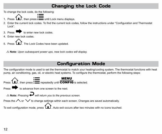
Configuration ModeTheconfigurationmodeisusedtosetthethermostattomatchyourheating/coolingsystem.Thethermostatfunctionswithheatpump,airconditioning,gas,oil,orelectricheatsystems.Toconfigurethethermostat,performthefollowingsteps:
Press ,thenpress repeatedlyuntil isselected.
Press toadvancefromonescreentothenext.
Note:Pressing will return you to the previous screen.
Pressthe or tochangesettingswithineachscreen.Changesaresavedautomatically.
Toexitconfigurationmode,press .Autoexitoccursaftertwominuteswithnoiconstouched.
Tochangethelockcode,dothefollowing:
1. Press ,thenpress untilLockmenudisplays.
2. Enterthecurrentlockcodes.Tofindthecurrentlockcodes,followtheinstructionsunder“ConfigurationandThermostatLock”.
3. Press toenternewlockcodes.
4. Enternewlockcodes.
5. Press .TheLockCodeshavebeenupdated.
Note:Upon subsequent power ups, new lock codes will display.
Changing the Lock Code

13
Configuration Mode SettingsThesetupscreensforConfigurationModeareasfollows:
1.TemperatureScale(ForC)
ChooseFahrenheitorCelsius.
Pressthe or toselect.
Press toadvancetothenextscreen.CONFIG
2.1stStageTemperatureDifferential(1°Fto5°F)(0.5°Cto2.5°C)
Setthenumberofdegreesbetweenyour“setpoint”temperatureandyour“turnon”temperature.
Pressthe or tosetdifferentialvalue.
Press toadvancetothenextscreen.CONFIG
3. 2ndStageTemperatureDifferential(1°Fto5°F)(0.5°Cto2.5°C) Note:Not for 1010W
Setthenumberofdegreesbetweenwhenstage1turnsonandwhenstage2turnson.
Pressthe or tosetdifferentialvalue.
Press toadvancetothenextscreen. CONFIG
4. 3rdStageTemperatureDifferential(1°Fto5°F)(0.5°Cto2.5°C) Note:Only for 3020W
Setthenumberofdegreesbetweenwhenstage2turnsonandwhenstage3turnson.
Pressthe or tosetdifferentialvalue.
Press toadvancetothenextscreen. CONFIG

14
7.HeatSource:Therearesixheatsourcesettings:
WARNING!: Incorrectsettingscandamagesystemand/orcausepotentiallydangerousconditions.UsethecodedescribedinConfigurationandThermostatLock.
Non-HeatPump
CONFIG
Electric
CONFIG
GasHeatPump
CONFIG
HeatPumpwith2compressorsandHeatActiveReversingValve
CONFIG
HeatPumpwith2compressorsandCoolActiveReversingValve
CONFIG
HeatPumpwith1compressorandHeatActiveReversingValve
CONFIG
HeatPumpwith1compressorandCoolActiveReversingValve
6.MinimumDeadband(1°Fto9°F)(1°Cto5°C)
SettheminimumseparationbetweenheatsetpointandcoolsetpointinAutoChangeoverMode.
Pressthe or tosetdeadbandvalue.
Press toadvancetothenextscreen.CONFIG
5.StagedOffOutputs
Selectwhethertheoutputsforheatingandcoolingarestagedoffindependentlyoraresatisfiedsimultaneously.
=Outputsoffsimultaneously(bestfordualfuel). =Outputsstagedoffindependently.
Note: For 2 compressor heat pumps and multi-stage gas/oil systems, stage 3 is staged off
independently when SO is set to .
Pressthe or toset.
Press toadvancetothenextscreen.
CONFIG

15
ForHeatPumpsWithElectricBackup(DF= )
Whentheambienttemperatureisabovetheselectedtemperature,theheatpumpwilloperateandelectricbackupwillbelockedout.Ambienttemperaturebetweentheselectedtemperatureswillresultinheatpumpandelectricback-upoperation.
Ambienttemperaturebelowthelowerselectedtemperaturewillresultinonlyelectricbackupoperating.
Heatpumpoperationonly
Bothheatpumpandelectricbackup
Electricbackuponly
Upper setpoint
Lower setpoint
°F/C
OutdoorTem
perature
HeatPumpwithElectricBackup(DF= )
ForHeatPumpsWithGas/OilBackup(DF= )
Whentheambienttemperatureisaboveselectedtemperature,onlytheheatpumpwilloperate.
Whentheambienttemperatureisbelowtheselectedtemperature,theheatpumpwillbelockedoutandonlythefurnacewilloperate.
Outdoor
Temperature
Set
poin
tHeatpumpoperationonly
Gas/oiloperationonly
°F/CHeatPumpwithGas/OilBackUp
(DF= )
HeatPumpwithGas/OilBackUp(DF= )
Outdoor
T emperature
Set
poin
t
Gas/oiloperationonly
°F/C
Heatpumpoperationwithgas/oilasauxiliarystage
ForHeatPumpsWithGas/OilBackup(DF= )
Whentheambienttemperatureisaboveselectedtemperature,heatpumpoperateswithauxiliarystageofgasoroilheat.
Whentheambienttemperatureisbelowtheselectedtemperature,theheatpumpwillbelockedoutandonlythefurnacewilloperate.
Remote Sensor When Used as Outdoor Sensor ( 3020 only)
8.*DualFuelSystem( , , )
Appearsonlyifheatpumpisselected.Fornon-heatpumpusers,pleaseskipthissectionandadvancetotheAuxiliaryDelayscreensonPage16.
=Heatpumpwithgas/oilfurnacebackup(seebelow).
=Heatpumpwithgas/oilfurnacebackup,butfurnacecanturnonduringwarmoutdoorconditions(seebelow).
=Heatpumpwithelectricbackup(seebelow).
Pressthe or toselect.Press toadvancetothenextscreen.
CONFIG

16
11.AuxiliaryDelayON(0-60minutes)Setthedelaytimeinminutesforauxiliaryheattobelockedoutafteracallforsecondstage.Thisextrasavingsfeatureisusedtotemporarilylockoutauxiliaryheatdevices,allowingjustheatpumptotrytosatisfyheatcall.
Pressthe or toselect.Press toadvancetothenextscreen.
CONFIG
HEAT
12.Lockout(0-8°,SLEEP,COOL-HEAT)Selectthenumberofdegreessettemperaturecanbechangedduringkeypadlockout.SLEEPsettinglocksthermostatonlyduringthesleepperiodtopreventafterhourstampering.COOL-HEATlockoutallowsadjustmentofthesettemperaturestothemaximumheatsettemperatureselectedandminimumcoolsettemperatureselected.Note:The mode cannot be changed while the thermostat is locked.
Pressthe or toselect.Press toadvancetothenextscreen.
CONFIG
10.OutdoorLowerSetpoint(select––todisable)
Appearsonlyforheatpumpwithelectricbackupwithoutdooruppersetpointenabled.
Note:Select lower setpoint for chart on previous page.
Pressthe or toselecttemperature.Press toadvancetothenextscreen.
CONFIG Low
WARNING!:Incorrectsettingscandamagesystemand/orcausepotentiallydangerousconditions.UsethecodedescribedinConfigurationSafetyLock.
Note:Select upper setpoint for chart on previous page. Select to disable.
Pressthe or toselect.
Press toadvancetothenextscreen.
9.OutdoorUpperSetpoint(50°Fto25°F,––)(10°Cto-4.0°C,––)
CONFIG
Hi
13.MaximumHeatSetpoint(45°Fto90°F)(7°Cto32°C)Adjusttocontrolthemaximumheatsettemperatureallowed.
Pressthe or toselect.Press toadvancetothenextscreen. CONFIG
HEAT

17
14.MinimumCoolSetpoint(45°Fto90°F)(7°Cto32°C)Adjusttocontroltheminimumcoolsettemperatureallowed.
Pressthe or toselect.Press toadvancetothenextscreen. CONFIG COOL
16.VacationHeatingSetpointTheseworkinconjunctionwiththeSchedulemodewhereyousetthedateandtimeofyourRETURNfromvacation(Page28).Untilthatdate/time,systemwillremainattheheatingsetpointspecifiedhere.
Pressthe or toselect.Press toadvancetothenextscreen.
CONFIG
HEAT
VACATION
15.VacationCoolingSetpointTheseworkinconjunctionwiththeSchedulemodewhereyousetthedateandtimeofyourRETURNfromvacation(Page28).Untilthatdate/time,systemwillremainatthecoolingsetpointspecifiedhere.
Pressthe or toselect.Press toadvancetothenextscreen.
CONFIG COOL
VACATION
17.RoomTemperatureOffset(+9°Fto-9°F)(+4.5°Cto-4.5°C)Adjusttocalibratedisplayedroomtemperaturetomatchactualroomtemperature.
Pressthe or toselect.Press toadvancetothenextscreen. CONFIG
CONFIG
18.MaximumCyclesAllowedPerHour(--,2-6)
=asmanyasneeded,2-6=maximumcycles/hour
Press or toselect.Press toadvancetothenextscreen.

18
WARNING!:Incorrectsettingscandamagesystemand/orcausepotentiallydangerousconditions.UsethecodedescribedinConfigurationSafetyLocktoaccessthisscreensetting.
19.TemperatureSensor(L,r,A,rsleep)
Note: If there is no remote sensor, option 1 (L) must be selected. May only be used with remote temperature sensor 1.
CONFIG
Appearsonlyfornon-heatpumpsystemsandheatpumpswithoutanoutdoorsensor.1.L–Onlyon-boardsensordeterminesroomtemperature.2.r–Onlyremotesensordeterminesroomtemperature.3.A–Averagetemperatureofon-boardandremotesensor.4.rSleep–Onlyon-boardsensorwillbeuseduntilSLEEPperiod,andthenonlyremotesensorisusedforSLEEPperiod.
Pressthe or toselect.Press toadvancetothenextscreen.
20.FanDelayOffTime(0,30,60,90seconds)
Selecttheamountoftimethefancontinuestooperateafterthecool/heatdemandhasbeensatisfied.Functionsforcooling,heatpumpsandelectricheat.
Press or toselect.
Press toadvancetothenextscreen.CONFIG
21.HourlyCycleFanOperation(1-30 minutes per hour)
UsedinconjunctionwiththeFanHOURLYmode.Whentheuserselectsthisoption,thefanwillturnonatthebeginningofeveryhourandrunforthenumberofminutesindicatedhere.
Press or toselect.
Press toadvancetothenextscreen.CONFIG
HOURLY
22.FanonSchedule(OFF,WAKE,LEAVE,RETURN,SLEEP)
ThefanwillruncontinuouslyduringthisscheduledperiodwhenthemodeisnotsettoOFF.Toturnonthefanduringoneofthescheduledperiods(WAKE,LEAVE,RETURN,SLEEP),pleasedothefollowing:
Press or toselect.
Press toadvancetothenextscreen.
CONFIG
ON
SCHEDULEFANOFF

19
24.ResetCheckFilterTimer
Usedtoresettheelapsednumberof(fanrunning)hoursfortheCheckFilterTimer.
Press or toselect (YES).
Press toadvancetothenextscreen. CONFIG
RESETCheckFilter
23.CheckFilterTimer(800-2500 hours)
Afterthenumberof(fanrunning)hoursspecified(forexample,1200hours),thewords“CHECKFILTER”willdisplaytoremindyoutocheck/changethesystemfilter.Thenextconfigurationscreeniswheretheelapsednumberofrunhourscanbereset.
Press or toselect.
Press toadvancetothenextscreen.
CONFIG
CheckFilter
25.Wi-FiReset
Afterinstallation,youwillhavetoresetWi-Fionyourthermostattoconnecttothewirelessnetworkforthefirsttime.Ifyouhavepreviouslyconnectedthethermostattothewirelessnetworkbuthavechangedyourpasswordorinstalledanewwirelessrouter,youwillhavetomanuallyreconnectthethermostattothewirelessnetworkasifforthefirsttime.
Note: If the thermostat has been connected to a wireless network before, the reset Wi-Fi configuration will be the last screen in the Configuration Menu. To easily access the screen
go to and press .Thenpress once – the reset Wi-Fi screen will display.
Press toselect (YES),the !willstartflashing.Press toexitconfigurationsettingmode.
Wi-Fi SetupThe thermostatiscompatiblewithanywirelessnetwork.Connectthermostattoawirelessnetwork,usingthefollowingsetps:
CreateAccountBeforeconnectingyourthermostattoaWi-Finetwork,youmustcreateauseraccount.Youcancreateanaccountthroughtheapponyoursmartdevice,orthroughthewebsite:http://www.captouchwifi.com.
ConnectingYourThermostattoWi-FiTherearethreedifferentmethodsyoucanusetoconnectyourthermostattoawirelessnetwork:usinganAppledevice,anAndroiddevice,oracomputerwithWi-Ficapabilities.
Note: If you are installing the thermostat for someone else, you can transfer the thermostat to the owner, using the app and the owner’s email address.
20
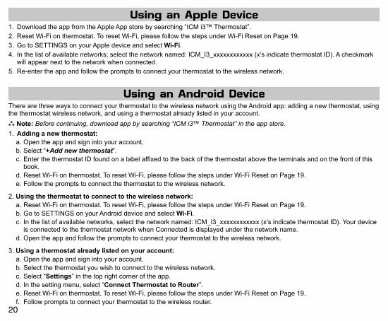
Using an Apple Device1. DownloadtheappfromtheAppleAppstorebysearching“ICMi3™Thermostat”.2. ResetWi-Fionthermostat.ToresetWi-Fi,pleasefollowthestepsunderWi-FiResetonPage19.3. GotoSETTINGSonyourAppledeviceandselectWi-Fi.4. Inthelistofavailablenetworks;selectthenetworknamed:ICM_I3_xxxxxxxxxxxx(x’sindicatethermostatID).Acheckmark
willappearnexttothenetworkwhenconnected.5. Re-entertheappandfollowthepromptstoconnectyourthermostattothewirelessnetwork.
Using an Android DeviceTherearethreewaystoconnectyourthermostattothewirelessnetworkusingtheAndroidapp:addinganewthermostat,usingthethermostatwirelessnetwork,andusingathermostatalreadylistedinyouraccount.
Note:Before continuing, download app by searching “ICM i3™ Thermostat” in the app store.
1.Addinganewthermostat:a.Opentheappandsignintoyouraccount.b.Select“+Add new thermostat”.c.EnterthethermostatIDfoundonalabelaffixedtothebackofthethermostatabovetheterminalsandonthefrontofthisbook.
d.ResetWi-Fionthermostat.ToresetWi-Fi,pleasefollowthestepsunderWi-FiResetonPage19.e.Followthepromptstoconnectthethermostattothewirelessnetwork.
2.Usingthethermostattoconnecttothewirelessnetwork:a.ResetWi-Fionthermostat.ToresetWi-Fi,pleasefollowthestepsunderWi-FiResetonPage19.b.GotoSETTINGSonyourAndroiddeviceandselectWi-Fi.c.Inthelistofavailablenetworks,selectthenetworknamed:ICM_I3_xxxxxxxxxxxx(x’sindicatethermostatID).YourdeviceisconnectedtothethermostatnetworkwhenConnectedisdisplayedunderthenetworkname.
d.Opentheappandfollowthepromptstoconnectyourthermostattothewirelessnetwork.
3.Usingathermostatalreadylistedonyouraccount:a.Opentheappandsignintoyouraccount.b.Selectthethermostatyouwishtoconnecttothewirelessnetwork.c.Select“Settings”inthetoprightcorneroftheapp.d.Inthesettingmenu,select“ConnectThermostattoRouter”.e.ResetWi-Fionthermostat.ToresetWi-Fi,pleasefollowthestepsunderWi-FiResetonPage19.f. Followpromptstoconnectyourthermostattothewirelessrouter.

21
TherearetwowaystoconnectyourthermostattoyourwirelessnetworkusingacomputerwithWi-Fi:usingtheWPSbuttononyourwirelessrouterorconnectingwithyourwirelessnetwork.Ifyoudonotrememberyourwirelesspassword,youcanusetheWPSbuttontoconnectyourthermostattothenetwork.
1. ResetWi-Fionthermostat.ToresetWi-Fi,pleasefollowthestepsunderWi-FiResetonPage19.
2. GotoNetworkSettingsinControlPanelandselectthenetworknamed:ICM_I3_xxxxxxxxxxxx(x’sindicatethermostatID
Youmayalsoconnecttothenetworkbyclickingon (Microsoft)or (Apple)andselectingthecorrectwirelessnetwork.
3. Inyourinternetbrowser,enterhttp://192.168.10.1/intheaddressline.
Using Your Wireless Network:a. Inthelistofavailablenetworks,selectthecorrectnetworkandenterpassword(ifpasswordprotected).
b. !willstopflashingand willdisplay,indicatingthethermostatissuccessfullyconnectedtoWi-Fi.
Using the WPS Button:a. Onyourwirelessrouter,presstheWPSbuttonuntiltherouterindicatesitissearchingforawirelessdevice.
b. Onyourcomputer,scrolltothebottomofthepageinthebrowserandselect“Go!”under“PresstheWPSbuttononyourWi-FiAccessPoint”.
c. !willstopflashingand willdisplay,indicatingthethermostatissuccessfullyconnectedtoWi-Fi.
4. Inyourinternetbrowser,enterhttp://www.captouchwifi.comintheaddressline.
5. Signintoyouraccount.
6. Under“Addthermostat”enterthethermostatID,foundonalabelaffixedtothebackofthethermostatandonthefrontofthisbook.
7. Enterthethermostatname,zipcode,anddescription.
Using a Computer with Wi-Fi

22
1.Intheapporthroughhttp://www.captouchwifi.com,changefanmodetoON.
2.Youwillhearaclickandsee displayedonthethermostatnexttofan.Thermostatissuccessfullyconnecttotheinternet.
3.Changethefanmodetothedesiredsetting.
Testing Wi-Fi Connection
Weather ScreenThethermostatallowsyoutoseethehighandlowtemperatureforthreedays,aswellasthecurrentoutdoortemperatureandrelativehumidityforthecurrentday–accordingtothezipcodeeneteredatthethermostatregistration.
Press ,thenpress until displays.
Press toadvancefromonescreentothenext.
Note:Pressing will return you to the previous screen.
Toexitweather,press .
Setting the Time and Date
1.Press ,thenpress untilCLOCKisdisplayed.
2.Press toenterdate/timesetting.Yearblinks.
3.Press or toselecttheyear.
4.Press tosavevalueandmovetomonth.
5.Press or toselectthemonth.
6.Press tosavevalueandmovetoday.
7.Press or toselecttheday.
8.Press tosavevalueandmovetohour.
9.Press or toselectthehour.
Note:As you move past 12:00, the AM/PM symbol will change automatically.
10. Press tosavethevalueandmovetominutes.
11.Press or toselecttheminutes.
12.Press toexitTime/Datesetting.
23
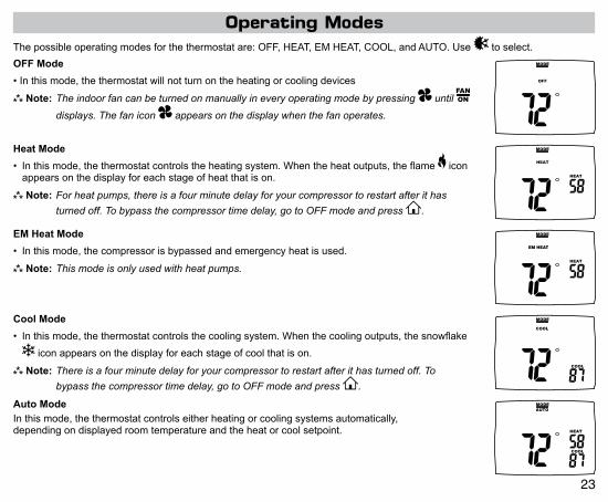
Operating Modes
OFFMode
•Inthismode,thethermostatwillnotturnontheheatingorcoolingdevices
Note:The indoor fan can be turned on manually in every operating mode by pressing until
displays. The fan icon appears on the display when the fan operates.
OFF
MODE
HeatMode
• Inthismode,thethermostatcontrolstheheatingsystem.Whentheheatoutputs,theflame iconappearsonthedisplayforeachstageofheatthatison.
Note:For heat pumps, there is a four minute delay for your compressor to restart after it has
turned off. To bypass the compressor time delay, go to OFF mode and press .
HEAT
HEAT
MODE
Thepossibleoperatingmodesforthethermostatare:OFF,HEAT,EMHEAT,COOL,andAUTO.Use toselect.
AutoModeInthismode,thethermostatcontrolseitherheatingorcoolingsystemsautomatically,dependingondisplayedroomtemperatureandtheheatorcoolsetpoint.
COOL
HEAT
AUTOMODE
CoolMode
• Inthismode,thethermostatcontrolsthecoolingsystem.Whenthecoolingoutputs,thesnowflake
iconappearsonthedisplayforeachstageofcoolthatison.
Note:There is a four minute delay for your compressor to restart after it has turned off. To
bypass the compressor time delay, go to OFF mode and press .
COOL
COOL
MODE
EMHeatMode
• Inthismode,thecompressorisbypassedandemergencyheatisused.
Note:This mode is only used with heat pumps.HEAT
MODE

24
Testing the Thermostat
HeatTest
1.Press ,thenpress untilheatmodeisdisplayed.
2.Adjustthesettemperaturesoitis5degreesabovetheroomtemperature.
3.Heatingshouldcomeonwithinafewseconds.
4.Adjustthesettemperature2degreesbelowtheroomtemperatureandtheheatshouldturnoff.Theremaybeafandelayonyoursystem.
Note:For heat pumps, there is a four-minute delay to protect your compressor after it turns off. To bypass the
compressor time delay, go to OFF mode and press .
CoolTest
1.Press ,thenpress untilcoolmodeisdisplayed.
2.Adjustsettemperaturesoitis5degreesbelowroomtemperature.
3.Coolingshouldcomeonwithinafewseconds.
4.Adjustthesettemperature2degreesabovetheroomtemperatureandthecoolingshouldturnoff.Theremaybeafandelayonyoursystem.
Note:There is a four-minute time delay to protect the compressor after it turns off. To bypass the
compressor time delay, go to OFF mode and press .
FanTest
1.Press ,thenpress icon. displays.IndoorfanturnsON.
2.Press ,thenpress icon. displays.IndoorfanturnsOFF.
Oncethethermostatisconfigured,itshouldbethoroughlytested.
CAUTION!: Do not energize the air conditioning system when the outdoor temperature is below 50 degrees. It can result in equipment damage or personal injury.
25
Setting the Program Schedule
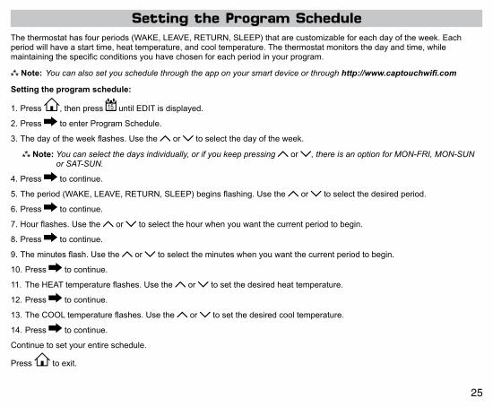
1.Press ,thenpress untilEDITisdisplayed.
2.Press toenterProgramSchedule.
3.Thedayoftheweekflashes.Usethe or toselectthedayoftheweek.
Note:You can select the days individually, or if you keep pressing or , there is an option for MON-FRI, MON-SUN or SAT-SUN.
4.Press tocontinue.
5.Theperiod(WAKE,LEAVE,RETURN,SLEEP)beginsflashing.Usethe or toselectthedesiredperiod.
6.Press tocontinue.
7.Hourflashes.Usethe or toselectthehourwhenyouwantthecurrentperiodtobegin.
8.Press tocontinue.
9.Theminutesflash.Usethe or toselecttheminuteswhenyouwantthecurrentperiodtobegin.
10.Press tocontinue.
11.TheHEATtemperatureflashes.Usethe or tosetthedesiredheattemperature.
12.Press tocontinue.
13.TheCOOLtemperatureflashes.Usethe or tosetthedesiredcooltemperature.
14.Press tocontinue.
Continuetosetyourentireschedule.
Press toexit.
Thethermostathasfourperiods(WAKE,LEAVE,RETURN,SLEEP)thatarecustomizableforeachdayoftheweek.Eachperiodwillhaveastarttime,heattemperature,andcooltemperature.Thethermostatmonitorsthedayandtime,whilemaintainingthespecificconditionsyouhavechosenforeachperiodinyourprogram.
Settingtheprogramschedule:
Note:You can also set you schedule through the app on your smart device or through http://www.captouchwifi.com

26
Press ,thenpress repeatedlyuntilthe optiondisplaysthenpress .
View Screen Options
Press toadvancetothenextscreen.
Press togotopreviousscreen.
Note:These screens are visible when the thermostat is locked or unlocked.
View program schedule settings
• OFF shows when schedule is off.
• SETTINGS show when schedule is on.
VIEW
SCHEDULE
SLEEPMon
View REMOTE SENSOR 1 temperature
if not used.
VIEW
Remote Sensor
VIEW
View if locked or unlocked
= Unlocked
= Locked
View REMOTE SENSOR 2 temperature
if not used.
VIEW
Remote Sensor
VIEW
Day
MonthYear
View month, day, and year
VIEW
View filter statusAccumulated fan run time displays.

27
VIEW
SLEEP
Display setpoints, fan, and program information
Press or toselect. = Don’t display setpoints and program schedule information.
= Always display setpoints and program schedule information.
REMOTE SENSOR 1 = REMOTE SENSOR 1 temperature will display.
REMOTE SENSOR 2 = REMOTE SENSOR 2 temperature will display.
Press toexit.
Setting the Vacation TimerThevacationtimerletsyousetthedateandtimeofyourRETURNfromvacation.Untilthatdate/time,thesystemwillremainattheVACATIONheatingandcoolingsetpointsspecifiedintheconfigurationmenu.
TousetheEASYVACATIONfeature:
Press ,thenpressthe toscrollto“Vacation”thenpress again.ThethermostatwillautomaticallygointoVacationmodewiththedefaultreturndate1monthlater.
Tosetthevacationtimer(andbeginvacationsetpointmode):
1.Press toselectoperatingmode.
2.Press ,thenpress untilVACATIONappears.
3.Press toenterthedateandtimeyouplantoRETURNfromvacation.
4.Whenyourfinishedenteringthedate/time,press .
Schedule OverrideThescheduleoverridefeatureallowstheusertooverridetheprogramschedulefor1to5hours.Inaddition,ifselected,theschedulecanbeoverriddenonlyuntilthenexttransitionperiod.
ToaccesstheScheduleoverridefeature,enterthe screen,thenuse toscrollthroughthemenuoptionsuntilyoureachtheSCHEDULEOVERRIDEscreen.Inthedefaultsetting,theVacation&ScheduleperiodswillbeflashingintheupperrightcorneroftheLCD.Inthismode,theVacation&Schedulewillbeoverriddenuntilthenexttransitionperiod.Toswitchtothe1-5houroverride,usethe arrow.ThismodeallowstheusertooverridetheSchedulesetpointsfor1-5hours.

28
WAKE LEAVE RETURN SLEEP
HEAT HEAT HEAT HEAT
COOL COOL COOL COOL
MONDAY
1
Usethefollowingpersonalprogramscheduletorecordyoursettings:
TUESDAY
2WAKE LEAVE RETURN SLEEP
HEAT HEAT HEAT HEAT
COOL COOL COOL COOL
WEDNESDAY
3WAKE LEAVE RETURN SLEEP
HEAT HEAT HEAT HEAT
COOL COOL COOL COOL
THURSDAY
4WAKE LEAVE RETURN SLEEP
HEAT HEAT HEAT HEAT
COOL COOL COOL COOL
MONDAYthru
SUNDAY
Factory Preprogramming
WAKE 6:00AM LEAVE 8:00AM RETURN 6:00PM SLEEP 10:00PM
HEAT 70°F HEAT 62°F HEAT 70°F HEAT 62°F
COOL 78°F COOL 85°F COOL 78°F COOL 82°F
Thethermostatcomespre-programmedwiththefollowingschedule:

29
Personal Program Schedule (continued)FRIDAY
5WAKE LEAVE RETURN SLEEP
HEAT HEAT HEAT HEAT
COOL COOL COOL COOL
SATURDAY
6WAKE LEAVE RETURN SLEEP
HEAT HEAT HEAT HEAT
COOL COOL COOL COOL
SUNDAY
7WAKE LEAVE RETURN SLEEP
HEAT HEAT HEAT HEAT
COOL COOL COOL COOL

30
Troubleshooting
Symptom RemedyNodisplay Checkfor24VACatthermostat;displayisblankwhen24VACisnotpresent.
Systemfandoesnotcomeonproperly Verifywiringiscorrect,checkheatsource(Gas/Electric)inConfiguration(seeSection7,Page14).
NoresponsewithfirstbuttonpressPress toactivatetouchicons.
Programscheduleactivatesatwrongtime Checktime(AM/PM)setonthermostat(seeSettingtheTime&Date,Page22).
Thermostatturnson/offtoofrequently Adjusttemperaturedifferential(seeConfigurationModeSetting,Pages12-13).
ThermostatdoesnotfollowprogramVerifythescheduleison :checktime(AM/PM);checkifinprogramoverride.
FanrunscontinuouslyPress andsettoauto . iscontinuousrun.
Roomtemperatureisnotcorrect Calibratethermostat(seeConfigurationModeSetting,Section17,Page17).Ifremotesensorisused,checkS1andS2terminalconnections.
LOCKdisplayswhenanybuttonispressed
Thermostathasthebuttonlockoutfunctionactivated(seeLockout&UnlockFeature,Page11).
ondisplayinsteadofroomtemperature
CheckforabadconnectionatS1andS2terminals,ifused(seeConfigurationModeSetting,Section19,Pages18).
HeatorCoolnotcomingon Verifywiringiscorrect,gentlypulloneachwiretoverifythereisagoodconnectionatterminalblock.
Remote SensordisplaysCheckremotesensorstemperatureat , ,
MENUVIEW, .
OVERRIDEdisplays Programscheduleisintemporaryoverride,itwillreturntoscheduleatnexttransitiontime.
ThermostatIDlocation ThethermostatIDisattachedtothefrontofthisbook,aswellasonthebackofthethermostatabovetheterminals.
notdisplayedonthermostat Reconnectthermostatasifforthefirsttime.
Nooutputsactivateuponpower-up UponPower-upthethermostatwillnotactivateoutputsforfourminutes.Tobypasstheoutputlockout,changethesetpointtemperatureinheatorcoolmodeonthethermostat,bythetemperaturedifferential.

31
Troubleshooting (continued)
Symptom RemedySetpointsdonotdisplayallofthetime
Press ,MENUVIEW , sixtimes,
Problemsconnectingusingtheapp
ConnectyourthermostatusingacomputerwithWi-Fi.Ifyouarehavingtrouble,thebestoptionistousetheWPSbutton(asdescribedunderUsingaComputerwithWi-Fi,Page21).
Problemfindingapp AppledevicesrequireiOS7.0ornewersoftware.AndroiddevicesrequireAndroidHoneycomb(Androidversion3.1)ornewersoftware.
Offline ! IfthethermostatorAPPshowsoffline( !)formorethanafewminutes,unplugthethermostatfromthewallplate,waitoneminute,thenplugthermostatbackintowallplate.
FCCComplianceStatement(Part15.19)
Thisdevicecomplieswithpart15oftheFCCRules.Operationissubjecttothefollowingtwoconditions:(1)Thisdevicemaynotcauseharmfulinterference,and(2)thisdevicemustacceptanyinterferencereceived,includinginterferencethatmaycauseundesiredoperation.
FCCPart15.21Statement
Modificationsorchangesmadetothedevice,notapprovedbytheoriginatingparty,mayvoiduserauthoritytooperatethedevice.
FCCRFExposureStatementToensureFCCandIndustryCanadacompliance,maintainaseparationdistanceof20cmfromdevice.
Section7.1.2ofRSS-GEN
UnderIndustryCanadaregulations,thisradiotransmittermayonlyoperateusinganantennaofatypeandmaximum(orlesser)gainapprovedforthetransmitterbyIndustryCanada.Toreducepotentialradiointerferencetootherusers,theantennatypeanditsgainshouldbesochosenthattheequivalentisotropicallyradiatedpower(e.i.r.p.)isnotmorethanthatnecessaryforsuccessfulcommunication.
Conformémentàlaréglementationd’IndustrieCanada,leprésentémetteurradiopeutfonctionneravecuneantenned’untypeetd’ungainmaximal(ouinférieur)approuvépourl’émetteurparIndustrieCanada.Danslebutderéduirelesrisquesdebrouillageradioélectriqueàl’intentiondesautresutilisateurs,ilfautchoisirletyped’antenneetsongaindesortequelapuissanceisotroperayonnéeéquivalente(p.i.r.e.)nedépassepasl’intensiténécessaireàl’établissementd’unecommunicationsatisfaisante.
Section7.1.3ofRSS-GEN
ThisdevicecomplieswithIndustryCanadalicense-exemptRSSstandard(s).Operationissubjecttothefollowingtwoconditions:(1)thisdevicemaynotcauseinterference,and(2)thisdevicemustacceptanyinterference,includinginterferencethatmaycauseundesiredoperationofthedevice.
LeprésentappareilestconformeauxCNRd’IndustrieCanadaapplicablesauxappareilsradioexemptsdelicence.L’exploitationestautoriséeauxdeuxconditionssuivantes:(1)l’appareilnedoitpasproduiredebrouillage,et(2)l’appareildoitacceptertoutbrouillageradioélectriquesubi,mêmesilebrouillageestsusceptibled’encompromettrelefonctionnement.
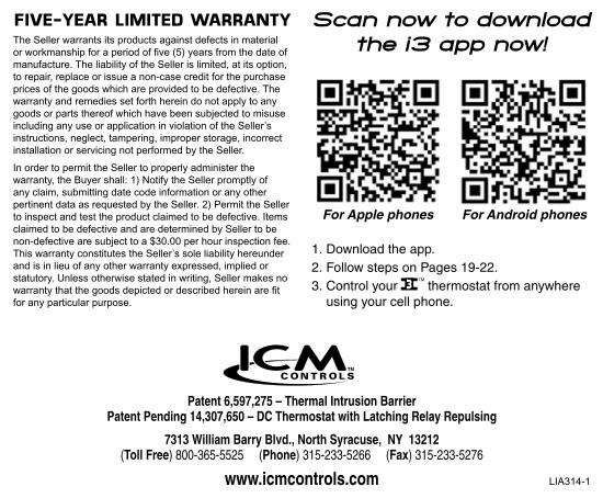
Patent 6,597,275 – Thermal Intrusion BarrierPatent Pending 14,307,650 – DC Thermostat with Latching Relay Repulsing
7313 William Barry Blvd., North Syracuse, NY 13212(Toll Free) 800-365-5525 (Phone) 315-233-5266 (Fax) 315-233-5276
www.icmcontrols.com
FIVE-YEAR LIMITED WARRANTYTheSellerwarrantsitsproductsagainstdefectsinmaterialorworkmanshipforaperiodoffive(5)yearsfromthedateofmanufacture.TheliabilityoftheSellerislimited,atitsoption,torepair,replaceorissueanon-casecreditforthepurchasepricesofthegoodswhichareprovidedtobedefective.ThewarrantyandremediessetforthhereindonotapplytoanygoodsorpartsthereofwhichhavebeensubjectedtomisuseincludinganyuseorapplicationinviolationoftheSeller’sinstructions,neglect,tampering,improperstorage,incorrectinstallationorservicingnotperformedbytheSeller.
InordertopermittheSellertoproperlyadministerthewarranty,theBuyershall:1)NotifytheSellerpromptlyofanyclaim,submittingdatecodeinformationoranyotherpertinentdataasrequestedbytheSeller.2)PermittheSellertoinspectandtesttheproductclaimedtobedefective.ItemsclaimedtobedefectiveandaredeterminedbySellertobenon-defectivearesubjecttoa$30.00perhourinspectionfee.ThiswarrantyconstitutestheSeller’ssoleliabilityhereunderandisinlieuofanyotherwarrantyexpressed,impliedorstatutory.Unlessotherwisestatedinwriting,Sellermakesnowarrantythatthegoodsdepictedordescribedhereinarefitforanyparticularpurpose.
LIA314-1
Scan now to download the i3 app now!
For Apple phones For Android phones
1. Download the app.2. Follow steps on Pages 19-22.3. Control your thermostat from anywhere
using your cell phone.