Embed Size (px)
Citation preview
Programat® CS4
Operating Instructions

3
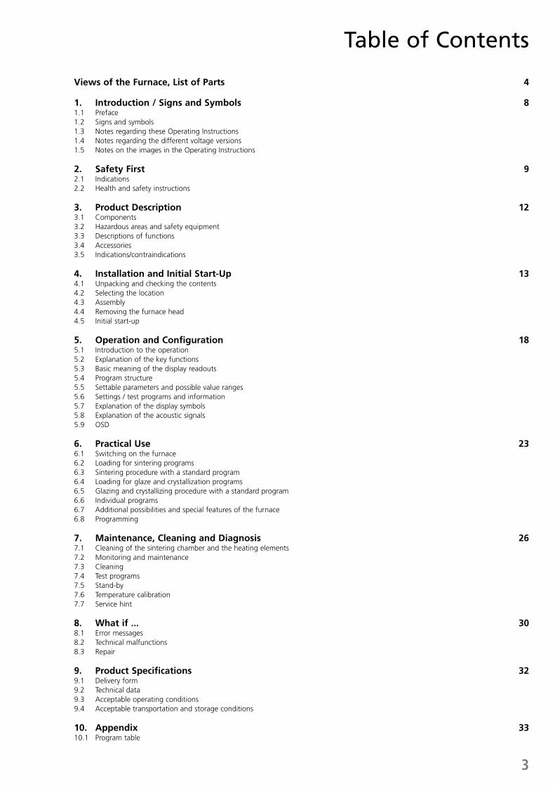
Views of the Furnace, List of Parts 4 1. Introduction / Signs and Symbols 81.1 Preface 1.2 Signs and symbols 1.3 Notes regarding these Operating Instructions1.4 Notes regarding the different voltage versions 1.5 Notes on the images in the Operating Instructions
2. Safety First 92.1 Indications 2.2 Health and safety instructions
3. Product Description 123.1 Components 3.2 Hazardous areas and safety equipment 3.3 Descriptions of functions3.4 Accessories3.5 Indications/contraindications
4. Installation and Initial Start-Up 134.1 Unpacking and checking the contents 4.2 Selecting the location 4.3 Assembly 4.4 Removing the furnace head4.5 Initial start-up
5. Operation and Configuration 185.1 Introduction to the operation 5.2 Explanation of the key functions 5.3 Basic meaning of the display readouts 5.4 Program structure 5.5 Settable parameters and possible value ranges 5.6 Settings / test programs and information 5.7 Explanation of the display symbols5.8 Explanation of the acoustic signals 5.9 OSD
6. Practical Use 236.1 Switching on the furnace6.2 Loading for sintering programs6.3 Sintering procedure with a standard program6.4 Loading for glaze and crystallization programs6.5 Glazing and crystallizing procedure with a standard program6.6 Individual programs6.7 Additional possibilities and special features of the furnace6.8 Programming 7. Maintenance, Cleaning and Diagnosis 267.1 Cleaning of the sintering chamber and the heating elements7.2 Monitoring and maintenance 7.3 Cleaning 7.4 Test programs 7.5 Stand-by7.6 Temperature calibration7.7 Service hint
8. What if ... 308.1 Error messages8.2 Technical malfunctions 8.3 Repair
9. Product Specifications 329.1 Delivery form 9.2 Technical data 9.3 Acceptable operating conditions9.4 Acceptable transportation and storage conditions
10. Appendix 3310.1 Program table
Table of Contents
4
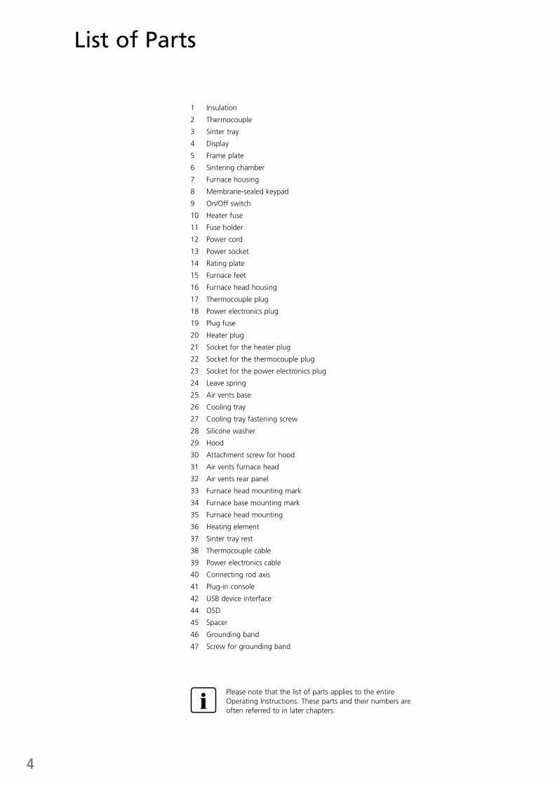
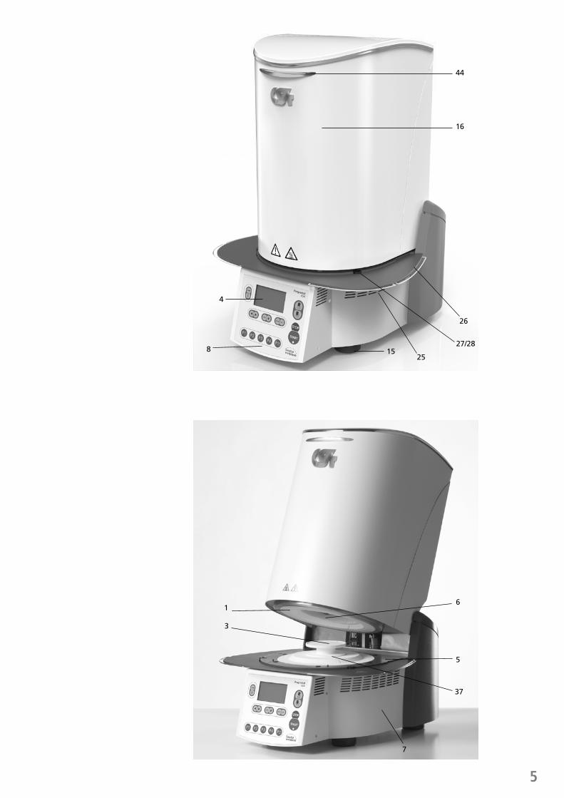
List of Parts
1 Insulation
2 Thermocouple
3 Sinter tray
4 Display
5 Frame plate
6 Sintering chamber
7 Furnace housing
8 Membrane-sealed keypad
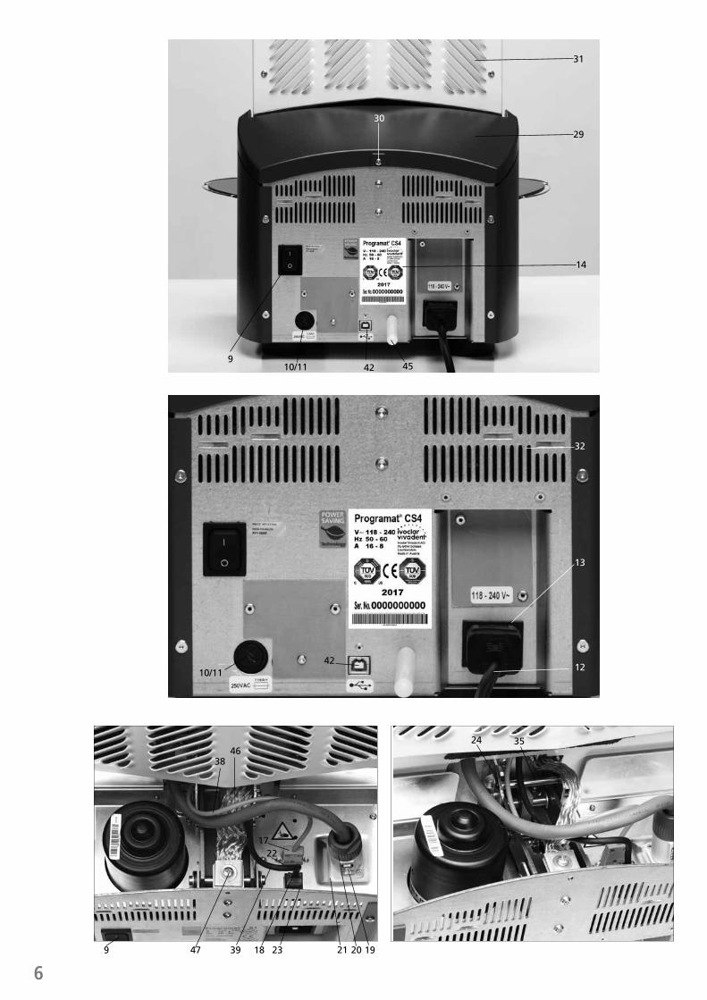
9 On/Off switch
10 Heater fuse
11 Fuse holder
12 Power cord
13 Power socket
14 Rating plate
15 Furnace feet
16 Furnace head housing
17 Thermocouple plug
18 Power electronics plug
19 Plug fuse
20 Heater plug
21 Socket for the heater plug
22 Socket for the thermocouple plug
23 Socket for the power electronics plug
24 Leave spring
25 Air vents base
26 Cooling tray
27 Cooling tray fastening screw
28 Silicone washer
29 Hood
30 Attachment screw for hood
31 Air vents furnace head
32 Air vents rear panel
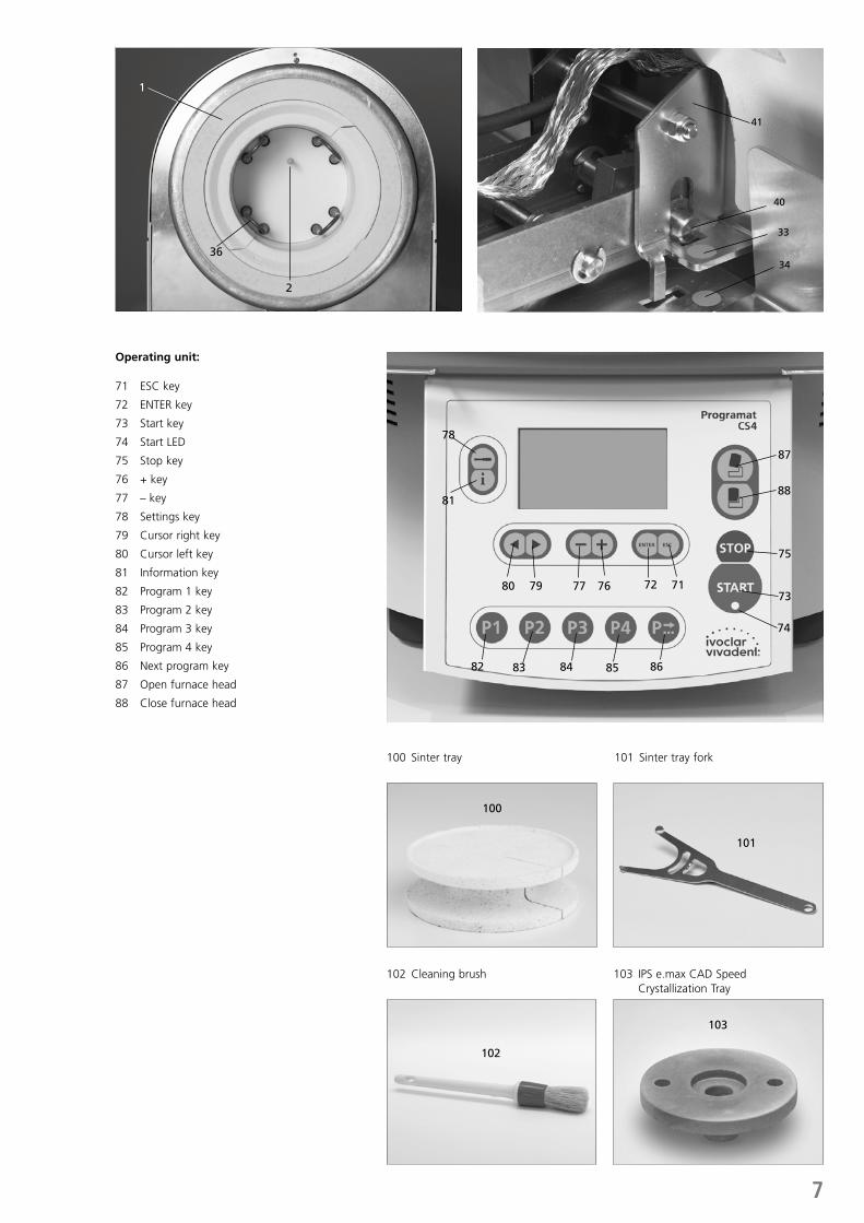
33 Furnace head mounting mark
34 Furnace base mounting mark
35 Furnace head mounting
36 Heating element
37 Sinter tray rest
38 Thermocouple cable
39 Power electronics cable
40 Connecting rod axis
41 Plug-in console
42 USB device interface
44 OSD
45 Spacer
46 Grounding band
47 Screw for grounding band
Please note that the list of parts applies to the entire Operating Instructions. These parts and their numbers are often referred to in later chapters.
5
List of Parts44
16
26
4
827/28
1525
1
3
6
5
37
7
639
1722
18 23 21 20 9
3846
47 19
24 35
910/11
10/11
14
31
30
29
42 45
13
12
32
42
7
Operating unit:
71 ESC key
72 ENTER key
73 Start key
74 Start LED
75 Stop key
76 + key
77 – key
78 Settings key
79 Cursor right key
80 Cursor left key
81 Information key
82 Program 1 key
83 Program 2 key
84 Program 3 key
85 Program 4 key
86 Next program key
87 Open furnace head
88 Close furnace head
100 Sinter tray
102 Cleaning brush 103 IPS e.max CAD Speed Crystallization Tray
101 Sinter tray fork
2
36
1
33
40
41
34
78
81
7980 77
82
101
100
102
103
83 84 85 86
72 71
74
73
75
76
88
87
8
1. Introduction / Signs and Symbols
1.1 Preface
Dear Customer
Thank you for having purchased the Programat® CS4. It is a sintering, glazing and crystallization furnace for dentists, who are in need of such a furnace for the CAD/CAM technique. The furnace enables sintering and glazing of ZrO2 materials such as IPS e.max® ZirCAD as well as glazing and crystallization of IPS e.max CAD, for example. It has been especially designed and constructed for this purpose.
The Programat CS4 has also been designed according to the latest industry standards. However, inappropriate use may damage the equipment and be harmful to personnel. Please observe the relevant safety instructions and read these Operating Instructions carefully.
Enjoy working with the Programat CS4.
1.2 Signs and symbols
The signs and symbols in these Operating Instructions facilitate the finding of important points and have the following meanings:
Symbol Note
Risks and dangers
Important information
Contraindication
Burn hazard
Risk of crushing
The Operating Instructions must be read.
1.3 Notes regarding the Operating Instructions
Apparatus: Programat CS4 Target group: Dentists, dental professionals
These Operating Instructions facilitate the correct, safe and economical use of the furnace.
Should you lose the Operating Instructions, extra copies can be ordered at a nominal fee from your local Ivoclar Vivadent Service Center or downloaded from the Internet free of charge (www.ivoclarvivadent.com).
1.4 Notes regarding the different voltage versions
The furnace has been designed for the following voltage range:
118–240V / 50–60 Hz
No manual switch-over is required for the use of the different voltage versions. Make sure that the local power supply complies with the voltage indicated on the rating plate before operating the furnace.
Only use the supplied original power cord. Do not use an inadequately measured replacement.
1.5 Notes on the images in the Operating Instructions
All images and illustrations in these Operating Instructions are used for exemplification and the details are not authoritative for the construction of the furnace. They are symbols which may slightly differ from the original, e.g. due to simplification.
9
2. Safety First
This chapter is especially important for individuals who work with the Programat CS4 or who have to carry out maintenance or repair work. This chapter must be read and the corresponding instructions followed!
2.1 Indications
The Programat CS 4 has been especially designed for the sintering and glazing of ZrO2 materials such as IPS e.max ZirCAD as well as glazing and crystallization of IPS e.max CAD, for example. The Programat CS4 should be used for this purpose only. Other uses than the ones stipulated, e.g. cooking of food, firing of other materials etc., are contraindicated. The manufacturer does not assume any liability for damage resulting from misuse. The user is solely responsible for any risk resulting from failure to observe these Instructions.
Further instructions to assure proper use of the furnace:
– The instructions, regulations and notes in these Operating Instructions must be observed.
– The instructions, regulations and notes in the material’s Instructions for Use must be observed.
– The furnace must be operated under the indicated environmental and operating conditions (see chapter 9).
– The Programat CS4 must be properly maintained.
Do not use colouring liquids containing chlorine or hydro- chloric acid in the Programat CS4 furnace. Due to the aggressive components of the liquids, the furnace surfaces or individual parts may be chemically corroded or damaged.
If colouring liquids containing chlorine or hydrochloric acid are used, irritating gases may develop during the heating phase.
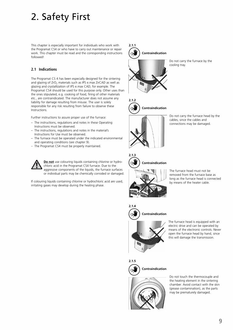
2.1.1 Contraindication
Do not carry the furnace by the cooling tray.
2.1.2 Contraindication
Do not carry the furnace head by the cables, since the cables and connections may be damaged.
2.1.3 Contraindication
The furnace head must not be removed from the furnace base as long as the furnace head is connected by means of the heater cable.
2.1.4
Contraindication
The furnace head is equipped with an electric drive and can be operated by means of the electronic controls. Never open the furnace head by hand, since this will damage the transmission.
2.1.5 Contraindication
Do not touch the thermocouple and the heating element in the sintering chamber. Avoid contact with the skin (grease contamination), as the parts may be prematurely damaged.
10
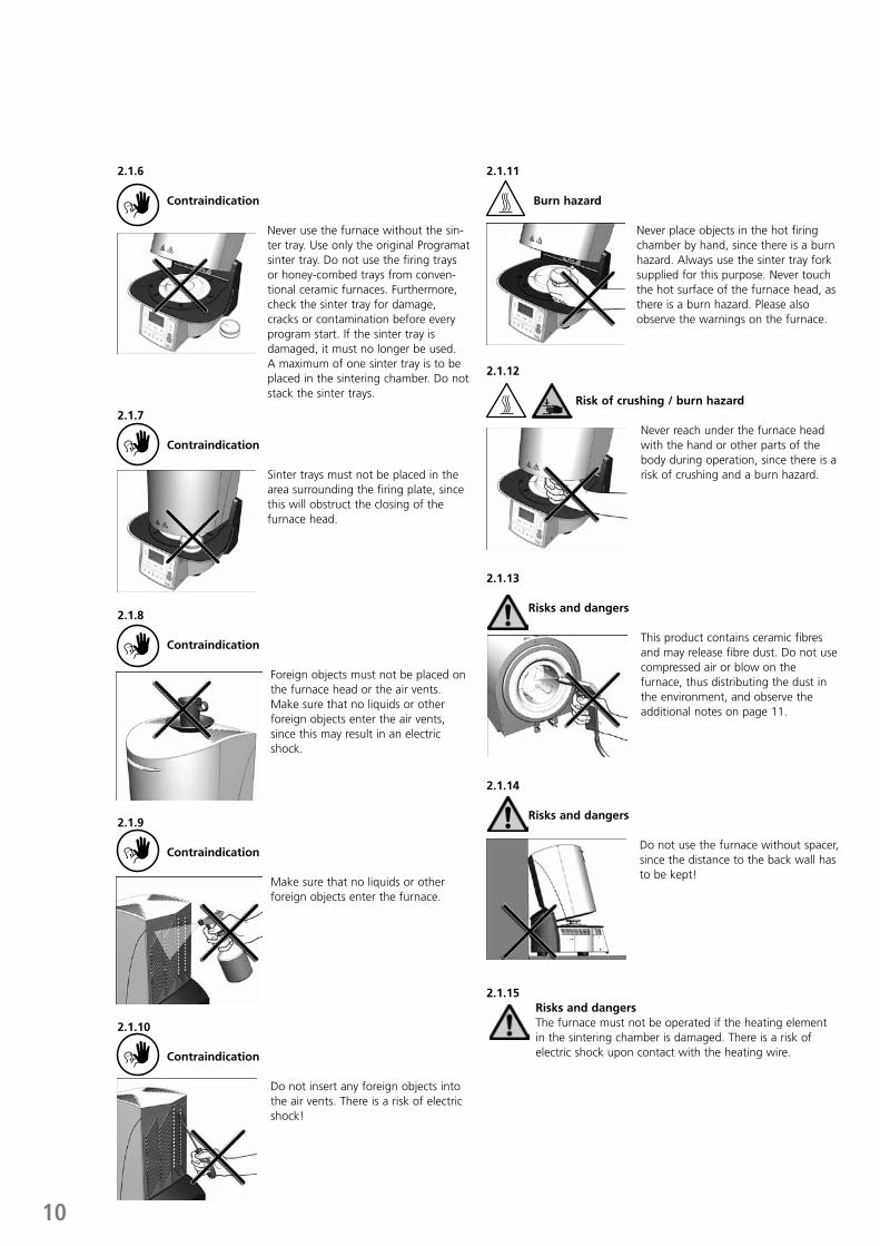
2.1.6 Contraindication
Never use the furnace without the sin-ter tray. Use only the original Programat sinter tray. Do not use the firing trays or honey-combed trays from conven-tional ceramic furnaces. Furthermore, check the sinter tray for damage, cracks or contamination before every program start. If the sinter tray is damaged, it must no longer be used. A maximum of one sinter tray is to be placed in the sintering chamber. Do not stack the sinter trays.
2.1.7 Contraindication
Sinter trays must not be placed in the area surrounding the firing plate, since this will obstruct the closing of the furnace head.
2.1.8 Contraindication
Foreign objects must not be placed on the furnace head or the air vents. Make sure that no liquids or other foreign objects enter the air vents, since this may result in an electric shock.
2.1.9 Contraindication
Make sure that no liquids or other foreign objects enter the furnace.
2.1.10 Contraindication
Do not insert any foreign objects into the air vents. There is a risk of electric shock!
2.1.11 Burn hazard
Never place objects in the hot firing chamber by hand, since there is a burn hazard. Always use the sinter tray fork supplied for this purpose. Never touch the hot surface of the furnace head, as there is a burn hazard. Please also observe the warnings on the furnace.
2.1.12 Risk of crushing / burn hazard
Never reach under the furnace head with the hand or other parts of the body during operation, since there is a risk of crushing and a burn hazard.
2.1.13
Risks and dangers
This product contains ceramic fibres and may release fibre dust. Do not use compressed air or blow on the furnace, thus distributing the dust in the environment, and observe the additional notes on page 11.
2.1.14
Risks and dangers
Do not use the furnace without spacer, since the distance to the back wall has to be kept!
2.1.15Risks and dangers The furnace must not be operated if the heating element in the sintering chamber is damaged. There is a risk of electric shock upon contact with the heating wire.
11
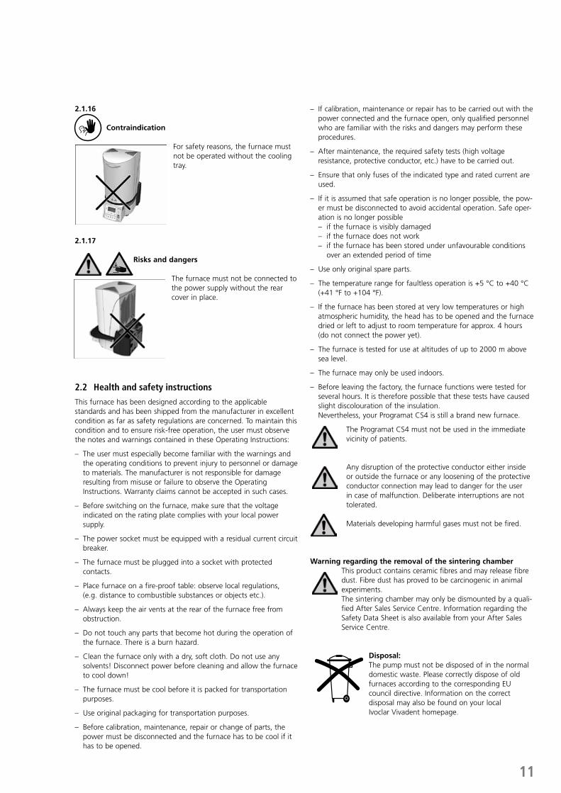
2.1.16 Contraindication
For safety reasons, the furnace must not be operated without the cooling tray.
2.1.17 Risks and dangers
The furnace must not be connected to the power supply without the rear cover in place.
2.2 Health and safety instructions
This furnace has been designed according to the applicable standards and has been shipped from the manufacturer in excellent condition as far as safety regulations are concerned. To maintain this condition and to ensure risk-free operation, the user must observe the notes and warnings contained in these Operating Instructions:
– The user must especially become familiar with the warnings and the operating conditions to prevent injury to personnel or damage to materials. The manufacturer is not responsible for damage resulting from misuse or failure to observe the Operating Instructions. Warranty claims cannot be accepted in such cases.
– Before switching on the furnace, make sure that the voltage indicated on the rating plate complies with your local power supply.
– The power socket must be equipped with a residual current circuit breaker.
– The furnace must be plugged into a socket with protected contacts.
– Place furnace on a fire-proof table: observe local regulations, (e.g. distance to combustible substances or objects etc.).
– Always keep the air vents at the rear of the furnace free from obstruction.
– Do not touch any parts that become hot during the operation of the furnace. There is a burn hazard.
– Clean the furnace only with a dry, soft cloth. Do not use any solvents! Disconnect power before cleaning and allow the furnace to cool down!
– The furnace must be cool before it is packed for transportation purposes.
– Use original packaging for transportation purposes.
– Before calibration, maintenance, repair or change of parts, the power must be disconnected and the furnace has to be cool if it has to be opened.
– If calibration, maintenance or repair has to be carried out with the power connected and the furnace open, only qualified personnel who are familiar with the risks and dangers may perform these procedures.
– After maintenance, the required safety tests (high voltage resistance, protective conductor, etc.) have to be carried out.
– Ensure that only fuses of the indicated type and rated current are used.
– If it is assumed that safe operation is no longer possible, the pow-er must be disconnected to avoid accidental operation. Safe oper-ation is no longer possible
– if the furnace is visibly damaged – if the furnace does not work – if the furnace has been stored under unfavourable conditions
over an extended period of time
– Use only original spare parts.
– The temperature range for faultless operation is +5 °C to +40 °C (+41 °F to +104 °F).
– If the furnace has been stored at very low temperatures or high atmospheric humidity, the head has to be opened and the furnace dried or left to adjust to room temperature for approx. 4 hours (do not connect the power yet).
– The furnace is tested for use at altitudes of up to 2000 m above sea level.
– The furnace may only be used indoors.
– Before leaving the factory, the furnace functions were tested for several hours. It is therefore possible that these tests have caused slight discolouration of the insulation.
Nevertheless, your Programat CS4 is still a brand new furnace.
The Programat CS4 must not be used in the immediate vicinity of patients.
Any disruption of the protective conductor either inside or outside the furnace or any loosening of the protective conductor connection may lead to danger for the user in case of malfunction. Deliberate interruptions are not tolerated.
Materials developing harmful gases must not be fired.
Warning regarding the removal of the sintering chamberThis product contains ceramic fibres and may release fibre dust. Fibre dust has proved to be carcinogenic in animal experiments. The sintering chamber may only be dismounted by a quali-fied After Sales Service Centre. Information regarding the Safety Data Sheet is also available from your After Sales Service Centre.
Disposal:The pump must not be disposed of in the normal domestic waste. Please correctly dispose of old furnaces according to the corresponding EU council directive. Information on the correct disposal may also be found on your local Ivoclar Vivadent homepage.
12
3. Product Description
3.1 Components
The Programat CS4 consists of the following components:– Furnace base with electronic controls– Furnace head with sintering chamber – Sinter tray – Crystallization tray– Cooling tray– Power cord – Sinter tray fork– Cleaning brush
3.2 Hazardous areas and safety equipment
Description of the hazardous areas of the furnace:
Hazardous area Type of risk
Sintering chamber Burn hazard
Opening and closing mechanism Risk of crushing
Electric components Risk of electric shock
Description of the safety equipment of the furnace:
Safety equipment Protective effect
Protective conductor Protection from electric shock
Electric fuses Protection from electric shock
Furnace housing and end caps Protection from electric shock, burning and crushing
3.3 Description of functions
The sintering chamber may be heated up to max. 1600 °C/2912 °F by means of a heating element. The process is controlled with the corresponding electronic controls and software. Moreover, the set and actual temperatures are continuously compared.
3.4 Accessories
– Sinter Furnace Temperature Checking Set UTH (880°C)– Sinter Furnace Temperature Checking Set MTH (1500°C)
3.5 Indications/contraindications
Indications– Sintering and glazing of ZrO2 materials (e.g. IPS e.max ZirCAD)– Crystallization and glazing (e.g. IPS e.max CAD)
Contraindications– The Programat CS4 is not suitable as a ceramic furnace for dental
laboratories.
13
4. Installation and Initial Start-Up
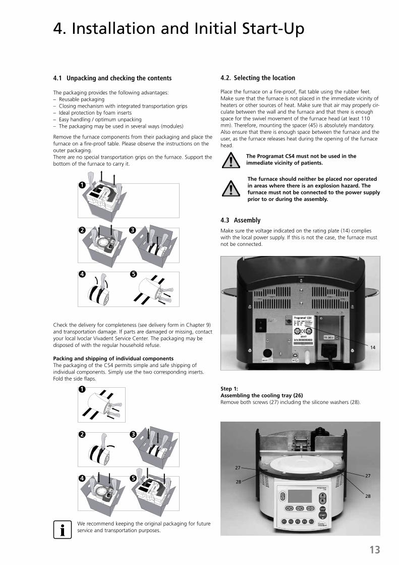
4.1 Unpacking and checking the contents
The packaging provides the following advantages:– Reusable packaging– Closing mechanism with integrated transportation grips– Ideal protection by foam inserts – Easy handling / optimum unpacking– The packaging may be used in several ways (modules) Remove the furnace components from their packaging and place the furnace on a fire-proof table. Please observe the instructions on the outer packaging.There are no special transportation grips on the furnace. Support the bottom of the furnace to carry it.
Check the delivery for completeness (see delivery form in Chapter 9) and transportation damage. If parts are damaged or missing, contact your local Ivoclar Vivadent Service Center. The packaging may be disposed of with the regular household refuse.
Packing and shipping of individual componentsThe packaging of the CS4 permits simple and safe shipping of individual components. Simply use the two corresponding inserts. Fold the side flaps.
3. Product Description
1 1
2
4 5
2 3
4 5
3
1 1
2
4 5
2 3
4 5
3
4.2. Selecting the location
Place the furnace on a fire-proof, flat table using the rubber feet. Make sure that the furnace is not placed in the immediate vicinity of heaters or other sources of heat. Make sure that air may properly cir-culate between the wall and the furnace and that there is enough space for the swivel movement of the furnace head (at least 110 mm). Therefore, mounting the spacer (45) is absolutely mandatory.Also ensure that there is enough space between the furnace and the user, as the furnace releases heat during the opening of the furnace head.
The Programat CS4 must not be used in the immediate vicinity of patients.
The furnace should neither be placed nor operated in areas where there is an explosion hazard. The furnace must not be connected to the power supply prior to or during the assembly.
4.3 Assembly
Make sure the voltage indicated on the rating plate (14) complies with the local power supply. If this is not the case, the furnace must not be connected.
We recommend keeping the original packaging for future service and transportation purposes.
Step 1: Assembling the cooling tray (26)Remove both screws (27) including the silicone washers (28).
28
2728
27
14
14
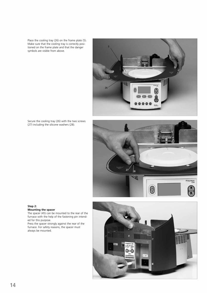
Step 2: Mounting the spacerThe spacer (45) can be mounted to the rear of the furnace with the help of the fastening pin intend-ed for this purpose. Press the spacer strongly against the rear of the furnace. For safety reasons, the spacer must always be mounted.
Secure the cooling tray (26) with the two screws (27) including the silicone washers (28).
Place the cooling tray (26) on the frame plate (5). Make sure that the cooling tray is correctly posi-tioned on the frame plate and that the danger symbols are visible from above.
27 28
26
5
15
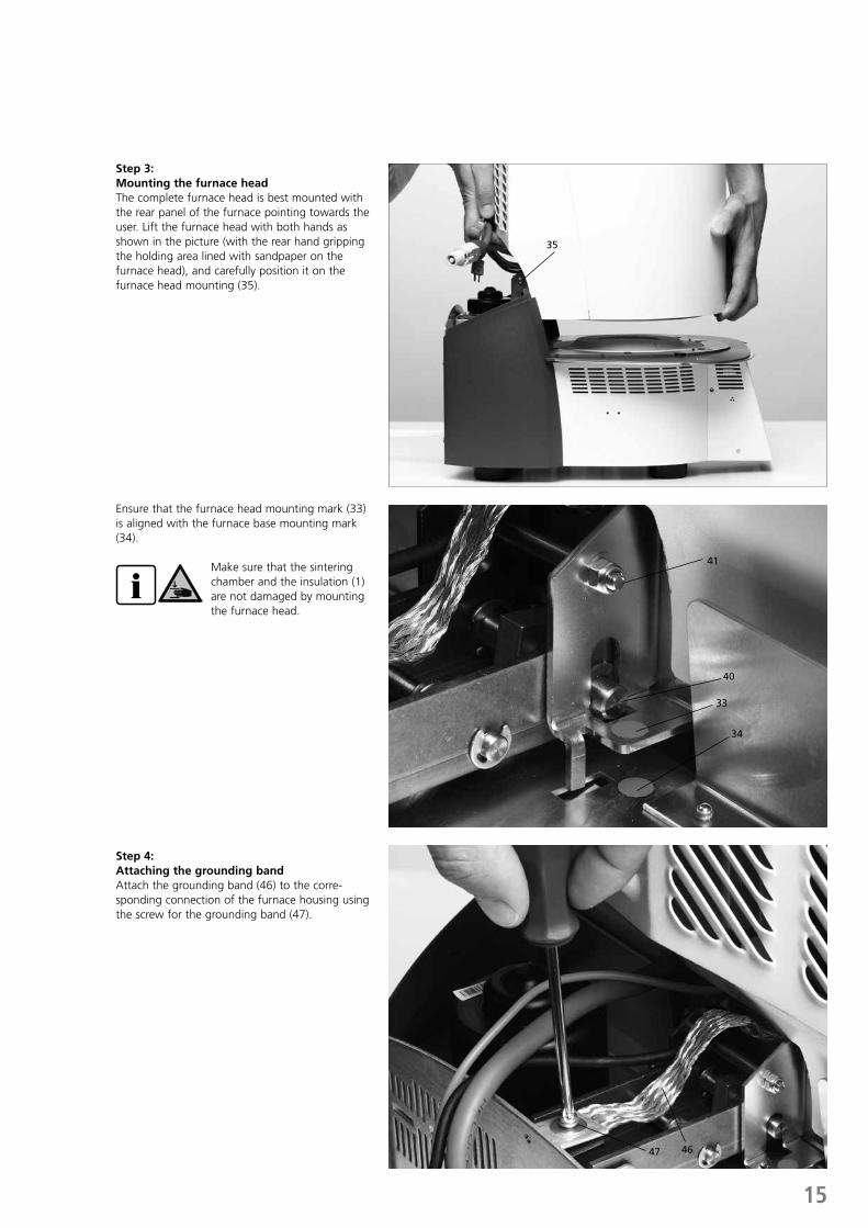
Step 3: Mounting the furnace headThe complete furnace head is best mounted with the rear panel of the furnace pointing towards the user. Lift the furnace head with both hands as shown in the picture (with the rear hand gripping the holding area lined with sandpaper on the furnace head), and carefully position it on the furnace head mounting (35).
Ensure that the furnace head mounting mark (33) is aligned with the furnace base mounting mark (34).
Make sure that the sintering chamber and the insulation (1) are not damaged by mounting the furnace head.
33
34
40
41
Step 4: Attaching the grounding bandAttach the grounding band (46) to the corre-sponding connection of the furnace housing using the screw for the grounding band (47).
47 46
35
16
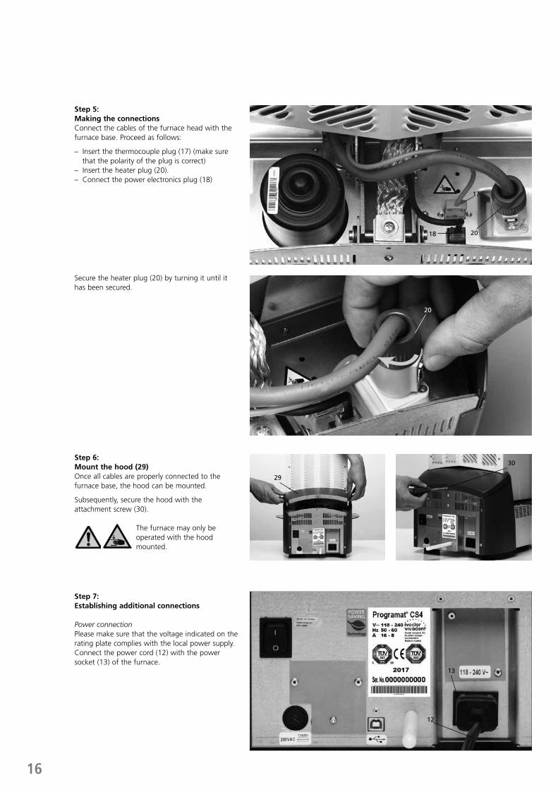
Secure the heater plug (20) by turning it until it has been secured.
Step 6: Mount the hood (29)Once all cables are properly connected to the furnace base, the hood can be mounted.
Subsequently, secure the hood with the attachment screw (30).
The furnace may only be operated with the hood mounted.
Step 7: Establishing additional connections
Power connection Please make sure that the voltage indicated on the rating plate complies with the local power supply. Connect the power cord (12) with the power socket (13) of the furnace.
20
12
13
29
30
Step 5: Making the connectionsConnect the cables of the furnace head with the furnace base. Proceed as follows:
– Insert the thermocouple plug (17) (make sure that the polarity of the plug is correct)
– Insert the heater plug (20).– Connect the power electronics plug (18)
2018
17
17
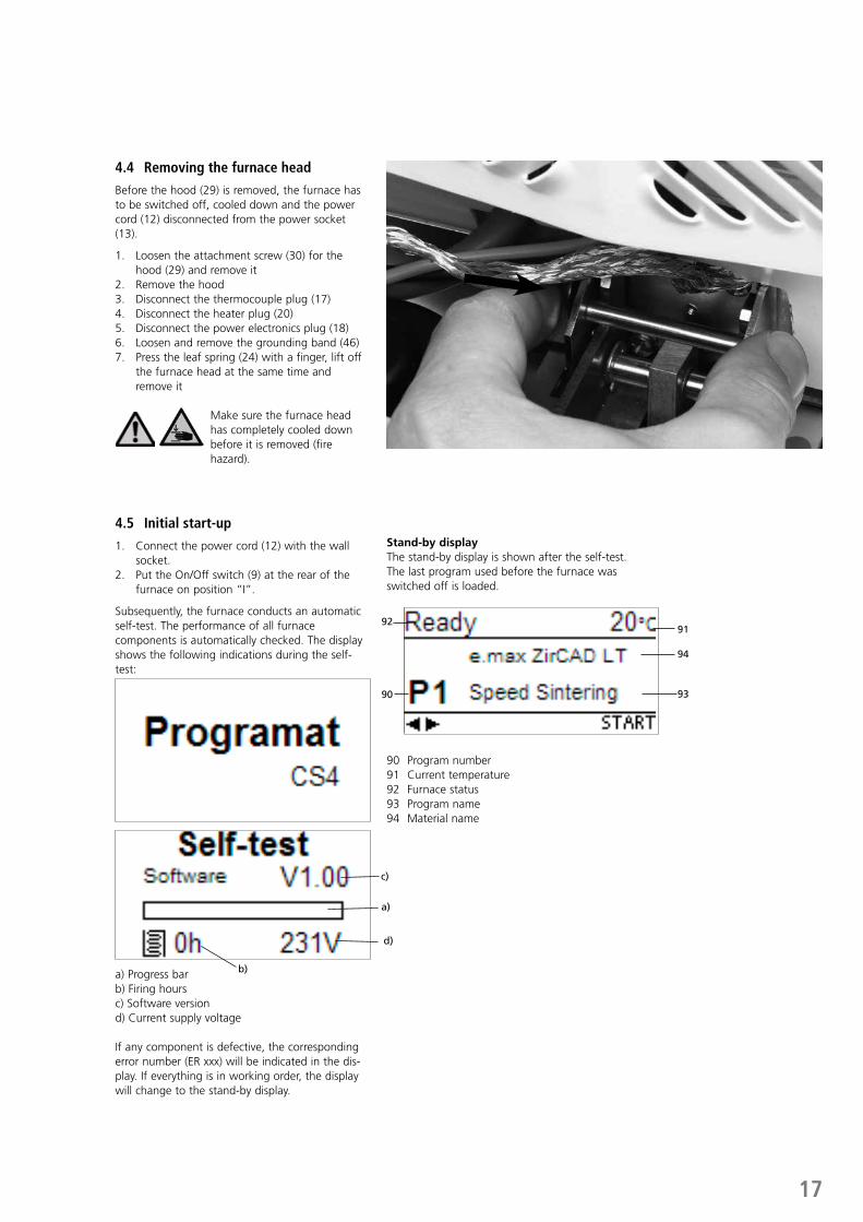
4.4 Removing the furnace head
Before the hood (29) is removed, the furnace has to be switched off, cooled down and the power cord (12) disconnected from the power socket (13).
1. Loosen the attachment screw (30) for the hood (29) and remove it
2. Remove the hood3. Disconnect the thermocouple plug (17) 4. Disconnect the heater plug (20)5. Disconnect the power electronics plug (18)6. Loosen and remove the grounding band (46)7. Press the leaf spring (24) with a finger, lift off
the furnace head at the same time and remove it
Make sure the furnace head has completely cooled down before it is removed (fire hazard).
4.5 Initial start-up
1. Connect the power cord (12) with the wall socket.
2. Put the On/Off switch (9) at the rear of the furnace on position “I”.
Subsequently, the furnace conducts an automatic self-test. The performance of all furnace components is automatically checked. The display shows the following indications during the self-test:
a) Progress bar b) Firing hoursc) Software versiond) Current supply voltage
If any component is defective, the corresponding error number (ER xxx) will be indicated in the dis-play. If everything is in working order, the display will change to the stand-by display.
Stand-by displayThe stand-by display is shown after the self-test. The last program used before the furnace was switched off is loaded.
90 Program number91 Current temperature92 Furnace status93 Program name94 Material name
91
94
9390
92
b)
d)
a)
c)
18
5. Operation and Configuration
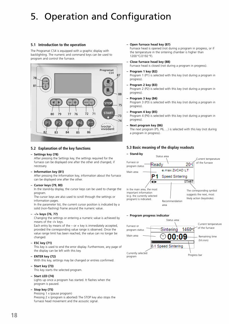
5.1 Introduction to the operation
The Programat CS4 is equipped with a graphic display with backlighting. The numeric and command keys can be used to program and control the furnace.
5.2 Explanation of the key functions
– Settings key (78) After pressing the Settings key, the settings required for the
furnace can be displayed one after the other and changed, if necessary.
– Information key (81) After pressing the Information key, information about the furnace
can be displayed one after the other.
– Cursor keys (79, 80) In the stand-by display, the cursor keys can be used to change the
program. The cursor keys are also used to scroll through the settings or
information pages. In the parameter list, the current cursor position is indicated by a
solid (non-flashing) frame around the numeric value.
– –/+ keys (76, 77) Changing the settings or entering a numeric value is achieved by
means of the -/+ keys. Each entry by means of the – or + key is immediately accepted,
provided the corresponding value range is observed. Once the value range limit has been reached, the value can no longer be changed.
– ESC key (71) This key is used to end the error display. Furthermore, any page of
the display can be left with this key.
– ENTER key (72) With this key, settings may be changed or entries confirmed.
– Start key (73) This key starts the selected program.
– Start LED (74) Lights up once a program has started. It flashes when the
program is paused.
– Stop key (75) Pressing 1 x (pause program) Pressing 2 x (program is aborted) The STOP key also stops the
furnace head movement and the acoustic signal.
– Open furnace head key (87) Furnace head is opened (not during a program in progress, or if
the temperature in the sintering chamber is higher than 1200 °C/2192 °F).
– Close furnace head key (88) Furnace head is closed (not during a program in progress).
– Program 1 key (82) Program 1 (P1) is selected with this key (not during a program in
progress).
– Program 2 key (83) Program 2 (P2) is selected with this key (not during a program in
progress).
– Program 3 key (84) Program 3 (P3) is selected with this key (not during a program in
progress).
– Program 4 key (85) Program 4 (P4) is selected with this key (not during a program in
progress).
– Next program key (86) The next program (P5, P6, ...) is selected with this key (not during
a program in progress).
5.3 Basic meaning of the display readouts
– Stand-by
– Program progress indicator
Status area
Recommendation area
The corresponding symbol suggests the next, most likely action (keystroke).
Furnace or program status
Current temperature of the furnace
Main area
In the main area, the most important information (e.g. the currently selected program) is indicated.
Status area
Progress bar
Remaining time (hh:mm)
Furnace or program status
Current temperature of the furnace
Main area
Currently selected program
78
81
7980 77
82 83 84 85 86
72 71
74
73
75
76
88
87
19
5.4 Program structure
The Programat CS4 basically offers two types of programs:
a) Standard program for materials of the Ivoclar Vivadent group (see enclosed Program Table)
e.g. IPS e.max ZirCAD, IPS e.max CAD
b) Free programs All the free programs are equal and available
as full-fledged programs. All the parameters can be individually set in each program.
When the furnace is delivered ex factory, the standard programs already contain the recommended material parameter settings.
The programs have been designed in such a way that 2 predrying stages, 3 heating stages, 2 cooling stages, and 1 opening time can be set.
In case one of these stages is not required, the time must be set to 00:00.
The predrying time includes the time of the heating phase and is no holding time.
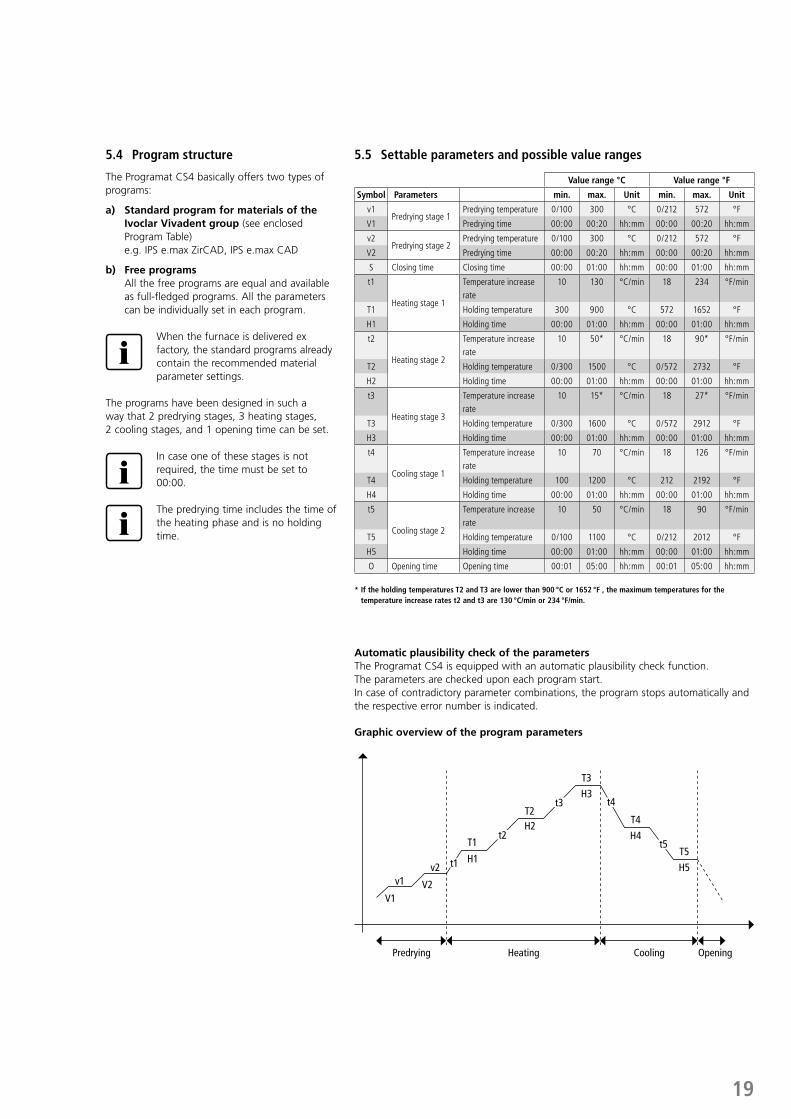
5.5 Settable parameters and possible value ranges
* If the holding temperatures T2 and T3 are lower than 900 °C or 1652 °F , the maximum temperatures for the temperature increase rates t2 and t3 are 130 °C/min or 234 °F/min.
Automatic plausibility check of the parametersThe Programat CS4 is equipped with an automatic plausibility check function. The parameters are checked upon each program start. In case of contradictory parameter combinations, the program stops automatically and the respective error number is indicated.
Value range °C Value range °F
Symbol Parameters min. max. Unit min. max. Unit
v1Predrying stage 1
Predrying temperature 0/100 300 °C 0/212 572 °F
V1 Predrying time 00:00 00:20 hh:mm 00:00 00:20 hh:mm
v2Predrying stage 2
Predrying temperature 0/100 300 °C 0/212 572 °F
V2 Predrying time 00:00 00:20 hh:mm 00:00 00:20 hh:mm
S Closing time Closing time 00:00 01:00 hh:mm 00:00 01:00 hh:mm
t1
Heating stage 1
Temperature increase rate
10 130 °C/min 18 234 °F/min
T1 Holding temperature 300 900 °C 572 1652 °F
H1 Holding time 00:00 01:00 hh:mm 00:00 01:00 hh:mm
t2
Heating stage 2
Temperature increase rate
10 50* °C/min 18 90* °F/min
T2 Holding temperature 0/300 1500 °C 0/572 2732 °F
H2 Holding time 00:00 01:00 hh:mm 00:00 01:00 hh:mm
t3
Heating stage 3
Temperature increase rate
10 15* °C/min 18 27* °F/min
T3 Holding temperature 0/300 1600 °C 0/572 2912 °F
H3 Holding time 00:00 01:00 hh:mm 00:00 01:00 hh:mm
t4
Cooling stage 1
Temperature increase rate
10 70 °C/min 18 126 °F/min
T4 Holding temperature 100 1200 °C 212 2192 °F
H4 Holding time 00:00 01:00 hh:mm 00:00 01:00 hh:mm
t5
Cooling stage 2
Temperature increase rate
10 50 °C/min 18 90 °F/min
T5 Holding temperature 0/100 1100 °C 0/212 2012 °F
H5 Holding time 00:00 01:00 hh:mm 00:00 01:00 hh:mm
O Opening time Opening time 00:01 05:00 hh:mm 00:01 05:00 hh:mm
Graphic overview of the program parameters
Predrying Heating Cooling Opening
V1
v1v2
H1
H2T2
T3
T4
T5
H3
H4
H5
T1
t1
t2
t3 t4
t5
V2
20
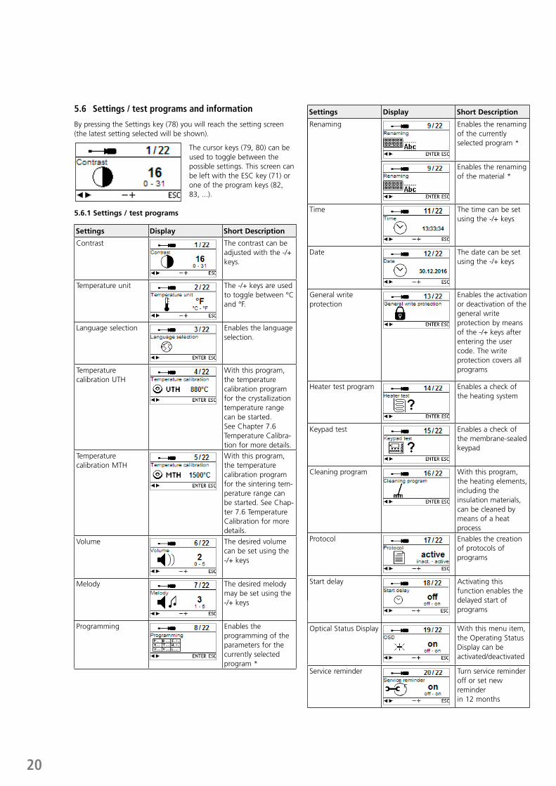
5.6 Settings / test programs and information
By pressing the Settings key (78) you will reach the setting screen (the latest setting selected will be shown).
The cursor keys (79, 80) can be used to toggle between the possible settings. This screen can be left with the ESC key (71) or one of the program keys (82, 83, ...).
5.6.1 Settings / test programs
Settings Display Short Description
Contrast The contrast can be adjusted with the -/+ keys.
Temperature unit The -/+ keys are used to toggle between °C and °F.
Language selection Enables the language selection.
Temperature calibration UTH
With this program, the temperature calibration program for the crystallization temperature range can be started. See Chapter 7.6 Temperature Calibra-tion for more details.
Temperature calibration MTH
With this program, the temperature calibration program for the sintering tem-perature range can be started. See Chap-ter 7.6 Temperature Calibration for more details.
Volume The desired volume can be set using the -/+ keys
Melody The desired melody may be set using the -/+ keys
Programming Enables the programming of the parameters for the currently selected program *
Settings Display Short Description
Renaming Enables the renaming of the currently selected program *
Enables the renaming of the material *
Time The time can be set using the -/+ keys
Date The date can be set using the -/+ keys
General write protection
Enables the activation or deactivation of the general write protection by means of the -/+ keys after entering the user code. The write protection covers all programs
Heater test program Enables a check of the heating system
Keypad test Enables a check of the membrane-sealed keypad
Cleaning program With this program, the heating elements, including the insulation materials, can be cleaned by means of a heat process
Protocol Enables the creation of protocols of programs
Start delay Activating this function enables the delayed start of programs
Optical Status Display With this menu item, the Operating Status Display can be activated/deactivated
Service reminder Turn service reminder off or set new reminder in 12 months
21
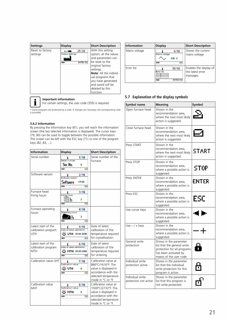
Settings Display Short Description
Reset to factory settings
With this setting option, all the values and parameters can be reset to the original factory settings. Note: All the individ-ual programs that you have generated and saved will be deleted by this function
Important informationFor certain settings, the user code (359) is required.
* Some programs are protected by a code. If changes are necessary, the corresponding code is provided.
5.6.2 InformationBy pressing the Information key (81), you will reach the information screen (the last selected information is displayed). The cursor keys (79, 80) can be used to toggle between the possible information. This screen can be left with the ESC key (71) or one of the program keys (82, 83, ...).
Information Display Short Description
Serial number Serial number of the furnace
Software version
Furnace headFiring hours
Furnace operating hours
Latest start of the calibration program UTH
Date of latest calibration of the temperature required for crystallization.
Latest start of the calibration program MTH
Date of latest calibration of the temperature required for sintering.
Calibration value UHT Calibration value at 880°C/1616°F. The value is displayed in accordance with the selected temperature mode in °C or °F.
Calibration value MHT
Calibration value at 1500°C/2732°F. The value is displayed in accordance with the selected temperature mode in °C or °F.
Information Display Short Description
Mains voltage Shows the current mains voltage
Error list Enables the display of the latest error messages.
5.7 Explanation of the display symbols
Symbol name Meaning Symbol
Open furnace head Shown in the recommendation area, where the next most likely action is suggested.
Close furnace head Shown in the recommendation area, where the next most likely action is suggested.
Press START Shown in the recommendation area, where the next most likely action is suggested.
Press STOP Shown in the recommendation area, where a possible action is suggested.
Press ENTER Shown in the recommendation area, where a possible action is suggested.
Press ESC Shown in the recommendation area, where a possible action is suggested.
Use cursor keys Shown in the recommendation area, where a possible action is suggested.
Use – / + keys Shown in the recommendation area, where a possible action is suggested.
General write protection
Shows in the parameter list that the general write protection for all programs has been activated by means of the user code.
Individual write protection active
Shows in the parameter list that the individual write protection for this program is active.
Individual write protection not active
Shows in the parameter list that this program is not write-protected.
22
5.8 Explanation of the acoustic signals
Basically, all the acoustic signals are played using the melody and volume selected by the user.The acoustic signal can only be stopped by pressing the STOP key.
– After the self-test has been completed In order to inform the user that the automatic self-test has been
successfully completed, an acoustic signal is played.
– In case of error messages Error messages are acoustically supported with the “error tune”
(endless beep). The beeper may be switched off with the STOP key, while the error message still remains visible. If the error message is acknowledged with ESC, the beeper also stops.
– At the end of a program In order to inform the user that the program has been completed,
an acoustic signal is played.
5.9 OSD
The OSD (Optical Status Display) integrated in the furnace head shows the most important statuses of the furnace. The following activities are indicated:
Colour Activities
Green Furnace is ready for use (self-test has been completed)
Red Program active, furnace busy
Yellow (flashing) Information, note or error message
23
6. Practical Use
The operating procedure for the Programat CS4 will be explained with the help of two examples: one standard and one individual program.
6.1 Switching on the furnace
Put On/Off switch (9) on position “I“. Subsequently, the furnace conducts an automatic self-test which will be indicated in the beginning. Subsequently, a status bar shows the progress of the self-test. Make sure that the furnace is not manipulated during this time.
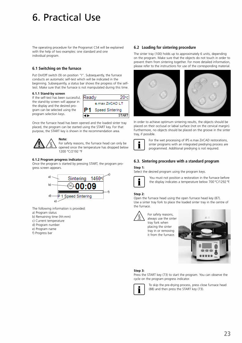
6.1.1 Stand-by screenIf the self-test has been successful, the stand-by screen will appear in the display and the desired pro-gram can be selected using the program selection keys.
Once the furnace head has been opened and the loaded sinter tray placed, the program can be started using the START key. For that purpose, the START key is shown in the recommendation area.
Note: For safety reasons, the furnace head can only be opened once the temperature has dropped below 1200 °C/2192 °F
6.1.2 Program progress indicatorOnce the program is started by pressing START, the program pro-gress screen appears.
The following information is provided:a) Program statusb) Remaining time (hh:mm)c) Current temperatured) Program numbere) Program namef) Progress bar
6.2 Loading for sintering procedure
The sinter tray (100) holds up to approximately 6 units, depending on the program. Make sure that the objects do not touch in order to prevent them from sintering together. For more detailed information, please refer to the instructions for use of the corresponding material.
In order to achieve optimum sintering results, the objects should be placed on their occlusal or labial surface (not on the cervical margin). Furthermore, no objects should be placed on the groove in the sinter tray, if possible.
For the wet processing of IPS e.max ZirCAD restorations, sinter programs with an integrated predrying process are programmed. Additional predrying is not required.
6.3. Sintering procedure with a standard program
Step 1:Select the desired program using the program keys.
You must not position a restoration in the furnace before the display indicates a temperature below 700 °C/1292 °F.
Step 2:Open the furnace head using the open furnace head key (87). Use a sinter tray fork to place the loaded sinter tray in the centre of the furnace.
For safety reasons, always use the sinter tray fork when placing the sinter tray in or removing it from the furnace.
Step 3:Press the START key (73) to start the program. You can observe the cycle on the program progress indicator.
To skip the pre-drying process, press close furnace head (88) and then press the START key (73).
f)
a)
b)
d)
c)
e)
24
Step 4:The furnace head opens automatically at the end of the program.
NoteThe sintering chamber is still very hot.
Use the sinter tray fork to remove the sinter tray and place it on the cooling tray. Allow the restoration to cool down to room temperature before further processing.
You must not position a new restoration in the sintering chamber before the display indicates a temperature below 700 °C /1292 °F.
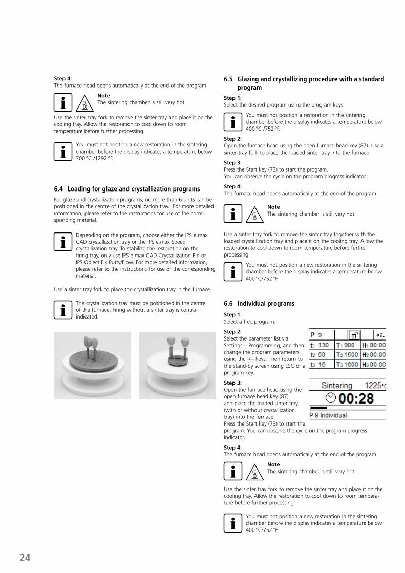
6.4 Loading for glaze and crystallization programs
For glaze and crystallization programs, no more than 6 units can be positioned in the centre of the crystallization tray. For more detailed information, please refer to the instructions for use of the corre-sponding material.
Depending on the program, choose either the IPS e.max CAD crystallization tray or the IPS e.max Speed crystallization tray. To stabilize the restoration on the firing tray, only use IPS e.max CAD Crystallization Pin or IPS Object Fix Putty/Flow. For more detailed information, please refer to the instructions for use of the corresponding material.
Use a sinter tray fork to place the crystallization tray in the furnace.
The crystallization tray must be positioned in the centre of the furnace. Firing without a sinter tray is contra-indicated.
6.5 Glazing and crystallizing procedure with a standard program
Step 1:Select the desired program using the program keys.
You must not position a restoration in the sintering chamber before the display indicates a temperature below 400 °C /752 °F.
Step 2:Open the furnace head using the open furnace head key (87). Use a sinter tray fork to place the loaded sinter tray into the furnace.
Step 3:Press the Start key (73) to start the program.You can observe the cycle on the program progress indicator.
Step 4:The furnace head opens automatically at the end of the program.
NoteThe sintering chamber is still very hot.
Use a sinter tray fork to remove the sinter tray together with the loaded crystallization tray and place it on the cooling tray. Allow the restoration to cool down to room temperature before further processing.
You must not position a new restoration in the sintering chamber before the display indicates a temperature below 400 °C/752 °F.
6.6 Individual programs
Step 1:Select a free program.
Step 2:Select the parameter list via Settings – Programming, and then change the program parameters using the -/+ keys. Then return to the stand-by screen using ESC or a program key.
Step 3:Open the furnace head using the open furnace head key (87)and place the loaded sinter tray (with or without crystallization tray) into the furnace. Press the Start key (73) to start the program. You can observe the cycle on the program progress indicator.
Step 4:The furnace head opens automatically at the end of the program.
NoteThe sintering chamber is still very hot.
Use the sinter tray fork to remove the sinter tray and place it on the cooling tray. Allow the restoration to cool down to room tempera-ture before further processing.
You must not position a new restoration in the sintering chamber before the display indicates a temperature below 400 °C/752 °F.
25
6.7 Additional possibilities and special features of the furnace
6.7.1 General write protectionIf all programs are write-protected, a closed, black lock appears on the parameter list. The setting “Renaming” cannot be selected if the general write protection is activated. As an indication, a closed lock is shown next to the keyboard symbol.
6.7.2 Stopping the running programA program in progress can be paused by pressing the STOP key once. If a program has been paused, the green LED in the START key flashes. Furthermore, the status shows as “Pause“. By pressing STOP a second time, the program can be aborted. It can be resumed by pressing START .
NoteIf the program has been aborted, the furnace head can be only opened once the temperature has dropped below 1200 °C/2192 °F.
6.7.3 Individual write protectionFor standard programs, the individual program write protection is activated by default to prevent accidental changes of the parameters. The individual program write protection (symbol) can be changed for each program via Settings – Programming using the -/+ keys.
6.7.4 RenamingVia Settings – Renaming, the keyboard can be selected, provided the currently selected program is not write-protected. The desired letters can be selected using the cursor keys (circular). The letter is selected with the ENTER key. Individual letters may be deleted using the delete key (arrow symbol).Changes are saved by pressing the save (disk symbol) or ESC key. This will also close the keyboard screen.
This key enables switching to lower case letters, numbers/ symbols and back to capital letters.
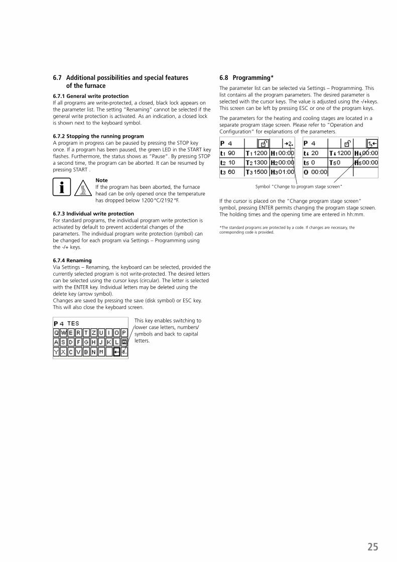
6.8 Programming*
The parameter list can be selected via Settings – Programming. This list contains all the program parameters. The desired parameter is selected with the cursor keys. The value is adjusted using the -/+keys. This screen can be left by pressing ESC or one of the program keys.
The parameters for the heating and cooling stages are located in a separate program stage screen. Please refer to “Operation and Configuration“ for explanations of the parameters.
Symbol "Change to program stage screen"
If the cursor is placed on the “Change program stage screen“ symbol, pressing ENTER permits changing the program stage screen. The holding times and the opening time are entered in hh:mm.
*The standard programs are protected by a code. If changes are necessary, the corresponding code is provided.
26
7. Maintenance, Cleaning and Diagnosis
This chapter describes the user maintenance and cleaning procedures for the Programat CS4. Only those tasks are listed that may be performed by dental professionals. All the other tasks must be performed by qualified service personnel at a certified Ivoclar Vivadent Service Center.
7.1 Cleaning of the sintering chamber and the heating elements
7.1.1 Visual inspection of the sintering chamberInspect the sintering chamber visually prior to every process. No foreign objects or dirt particles must be present in the sintering chamber during the sintering, glazing or crystallization procedure. Contaminations may be due to chipping of the oxide / protective layer of the heating element surface, among others. This type of contamination may have an effect on the optical properties (discolouration) of the object. Contaminations resulting from chipping of the oxide layer can be classified as follows:
Type of contamination
Indicator
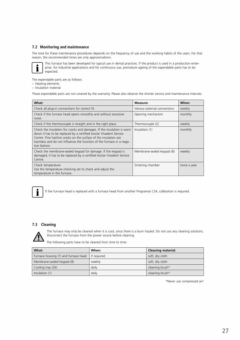
Glass particles The insulation of the lower part of the furnace / the sinter tray rest shows residue of clearly visible, glassy transparent particles (see image a).
Fine glass dust The insulation of the lower part of the furnace and the cooling tray show residue of fine glass dust. This type of contamination is more difficult to discern.
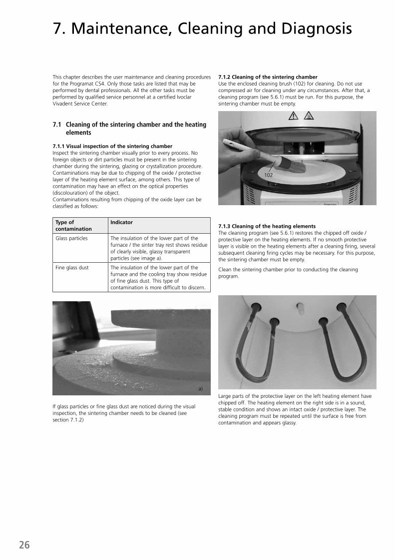
7.1.2 Cleaning of the sintering chamberUse the enclosed cleaning brush (102) for cleaning. Do not use compressed air for cleaning under any circumstances. After that, a cleaning program (see 5.6.1) must be run. For this purpose, the sintering chamber must be empty.
7.1.3 Cleaning of the heating elementsThe cleaning program (see 5.6.1) restores the chipped off oxide / protective layer on the heating elements. If no smooth protective layer is visible on the heating elements after a cleaning firing, several subsequent cleaning firing cycles may be necessary. For this purpose, the sintering chamber must be empty.
Clean the sintering chamber prior to conducting the cleaning program.
If glass particles or fine glass dust are noticed during the visual inspection, the sintering chamber needs to be cleaned (see section 7.1.2)
Large parts of the protective layer on the left heating element have chipped off. The heating element on the right side is in a sound, stable condition and shows an intact oxide / protective layer. The cleaning program must be repeated until the surface is free from contamination and appears glassy.
a)
102
27
7.2 Monitoring and maintenance
The time for these maintenance procedures depends on the frequency of use and the working habits of the users. For that reason, the recommended times are only approximations.
This furnace has been developed for typical use in dental practices. If the product is used in a production enter-prise, for industrial applications and for continuous use, premature ageing of the expendable parts has to be expected.
The expendable parts are as follows:– Heating elements– Insulation material
These expendable parts are not covered by the warranty. Please also observe the shorter service and maintenance intervals.
If the furnace head is replaced with a furnace head from another Programat CS4, calibration is required.
7.3 Cleaning
The furnace may only be cleaned when it is cool, since there is a burn hazard. Do not use any cleaning solutions. Disconnect the furnace from the power source before cleaning.
The following parts have to be cleaned from time to time:
What: When: Cleaning material:
Furnace housing (7) and furnace head if required soft, dry cloth
Membrane-sealed keypad (8) weekly soft, dry cloth
Cooling tray (26) daily cleaning brush*
Insulation (1) daily cleaning brush*
*Never use compressed air!
What: Measure: When:
Check all plug-in connections for correct fit. Various external connections weekly
Check if the furnace head opens smoothly and without excessive noise.
Opening mechanism monthly
Check if the thermocouple is straight and in the right place. Thermocouple (2) weekly
Check the insulation for cracks and damages. If the insulation is worn down it has to be replaced by a certified Ivoclar Vivadent Service Centre. Fine hairline cracks on the surface of the insulation are harmless and do not influence the function of the furnace in a nega-tive fashion.
Insulation (1) monthly
Check the membrane-sealed keypad for damage. If the keypad is damaged, it has to be replaced by a certified Ivoclar Vivadent Service Centre.
Membrane-sealed keypad (8) weekly
Check temperatureUse the temperature checking set to check and adjust the temperature in the furnace.
Sintering chamber twice a year
28
7.4 Test programs
Press the Settings key and scroll to the desired test program using the cursor keys.
Heater test programThe heater test automatically checks the heating system. The test should only be performed with the sintering chamber empty, since any mass placed in the furnace (e.g. sinter tray) would influence the result.
Keypad test programEach pressing of a key results in a short beep. The keypad test can be closed using the ESC key.
Cleaning programThe heating elements are “cleaned“ and/or regenerated using the cleaning program.
7.5 Stand-by
We recommend keeping the furnace head closed during stand-by to prevent damage.
7.6 Temperature calibration
The temperature level in the sintering chamber may change after prolonged operating hours (e.g. by contamination, wear and tear of the heating elements etc.). For optimum function, regular recalibration is required (see 7.2).
The calibration with temperature control ring enables the verification of the temperature of 880 °C/1616 °F (UTH) and 1500 °C/2732 °F (MTH) respectively, which is required for crystallization, glazing and sintering in the sintering chamber. The calibration of both tempera-ture ranges is not strictly required. If only sintering programs are used, the calibration has to be done for MTH (1500 °C/2732 °F). If only glazing and crystallization programs are used, the calibration has to be done for UTH (880 °C/1616 °F). During the calibration process, the rings change their dimensions due to shrinkage. The shrinkage of the temperature control rings is decisive for the correc-tion value of the furnace and can be found on the conversion table (enclosed in the Temperature Checking Set). Conduct the tempera-ture calibration only when the furnace is cold.
For calibration, you need temperature control rings, a measuring device (slide gauge) and a conversion table (enclosed in the Tempera-ture Checking Set).
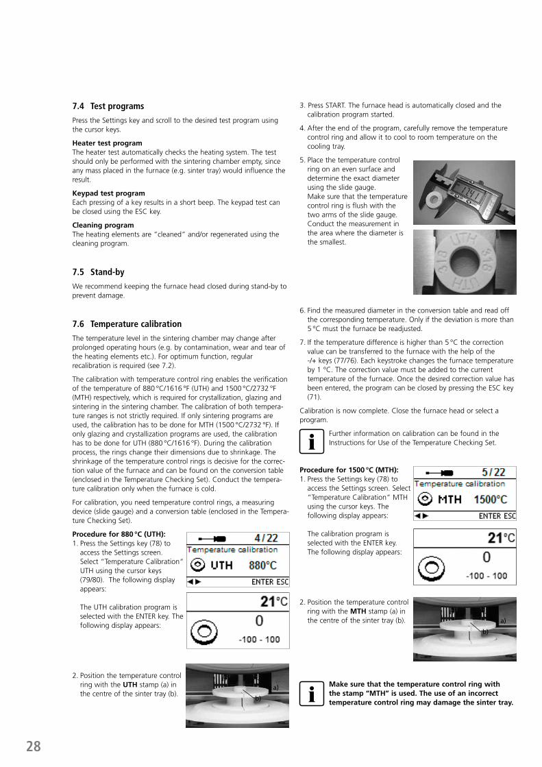
Procedure for 880 °C (UTH):1. Press the Settings key (78) to
access the Settings screen. Select “Temperature Calibration“ UTH using the cursor keys (79/80). The following display appears:
The UTH calibration program is selected with the ENTER key. The following display appears:
2. Position the temperature control ring with the UTH stamp (a) in the centre of the sinter tray (b).
3. Press START. The furnace head is automatically closed and the calibration program started.
4. After the end of the program, carefully remove the temperature control ring and allow it to cool to room temperature on the cooling tray.
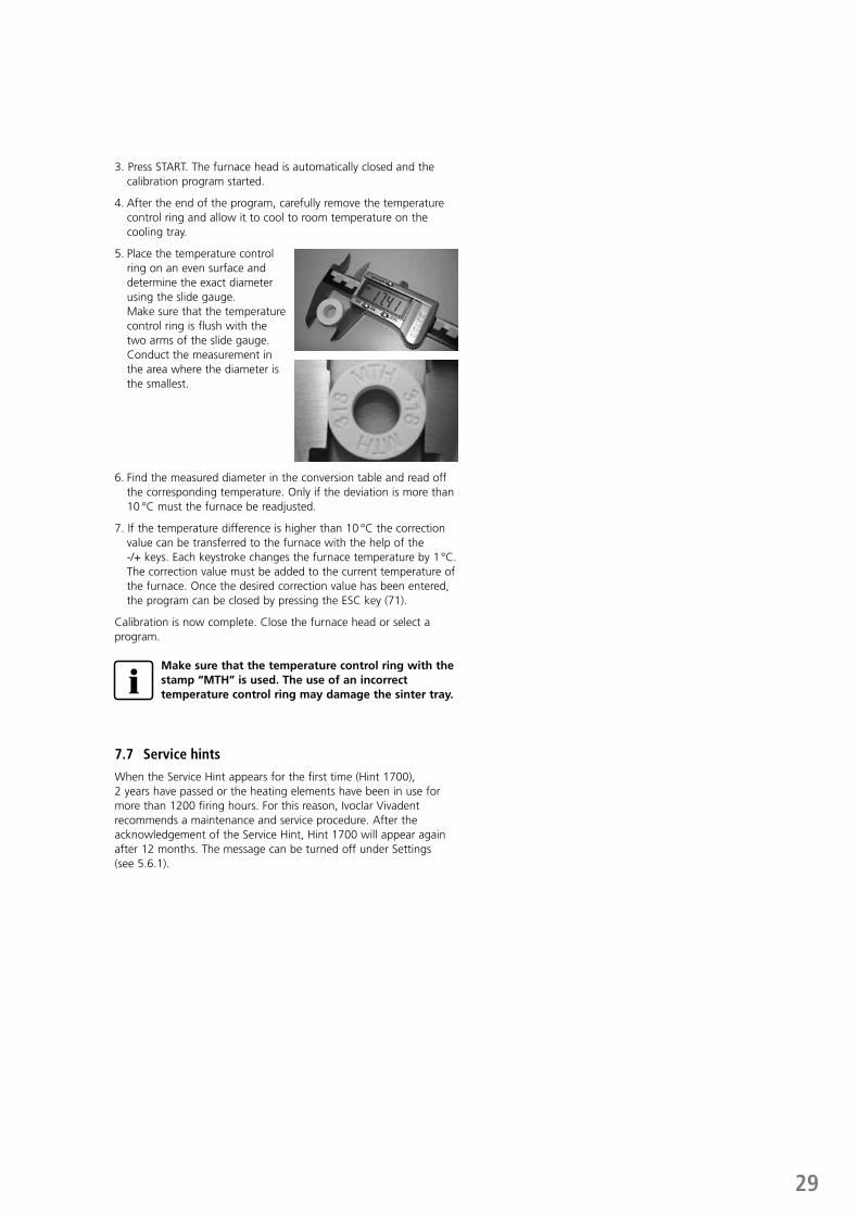
5. Place the temperature control ring on an even surface and determine the exact diameter using the slide gauge. Make sure that the temperature control ring is flush with the two arms of the slide gauge. Conduct the measurement in the area where the diameter is the smallest.
6. Find the measured diameter in the conversion table and read off the corresponding temperature. Only if the deviation is more than 5 °C must the furnace be readjusted.
7. If the temperature difference is higher than 5 °C the correction value can be transferred to the furnace with the help of the -/+ keys (77/76). Each keystroke changes the furnace temperature by 1 °C. The correction value must be added to the current temperature of the furnace. Once the desired correction value has been entered, the program can be closed by pressing the ESC key (71).
Calibration is now complete. Close the furnace head or select a program.
Further information on calibration can be found in the Instructions for Use of the Temperature Checking Set.
Procedure for 1500 °C (MTH):1. Press the Settings key (78) to
access the Settings screen. Select “Temperature Calibration“ MTH using the cursor keys. The following display appears:
The calibration program is selected with the ENTER key. The following display appears:
2. Position the temperature control ring with the MTH stamp (a) in the centre of the sinter tray (b).
Make sure that the temperature control ring with the stamp “MTH” is used. The use of an incorrect temperature control ring may damage the sinter tray.
a)
b)
a)
b)
29
3. Press START. The furnace head is automatically closed and the calibration program started.
4. After the end of the program, carefully remove the temperature control ring and allow it to cool to room temperature on the cooling tray.
5. Place the temperature control ring on an even surface and determine the exact diameter using the slide gauge. Make sure that the temperature control ring is flush with the two arms of the slide gauge. Conduct the measurement in the area where the diameter is the smallest.
6. Find the measured diameter in the conversion table and read off the corresponding temperature. Only if the deviation is more than 10 °C must the furnace be readjusted.
7. If the temperature difference is higher than 10 °C the correction value can be transferred to the furnace with the help of the -/+ keys. Each keystroke changes the furnace temperature by 1 °C. The correction value must be added to the current temperature of the furnace. Once the desired correction value has been entered, the program can be closed by pressing the ESC key (71).
Calibration is now complete. Close the furnace head or select a program.
Make sure that the temperature control ring with the stamp “MTH” is used. The use of an incorrect temperature control ring may damage the sinter tray.
7.7 Service hints
When the Service Hint appears for the first time (Hint 1700), 2 years have passed or the heating elements have been in use for more than 1200 firing hours. For this reason, Ivoclar Vivadent recommends a maintenance and service procedure. After the acknowledgement of the Service Hint, Hint 1700 will appear again after 12 months. The message can be turned off under Settings (see 5.6.1).
30
8. What if ...
This chapter will help you to recognize malfunctions and take appropriate measures.
8.1 Error messages
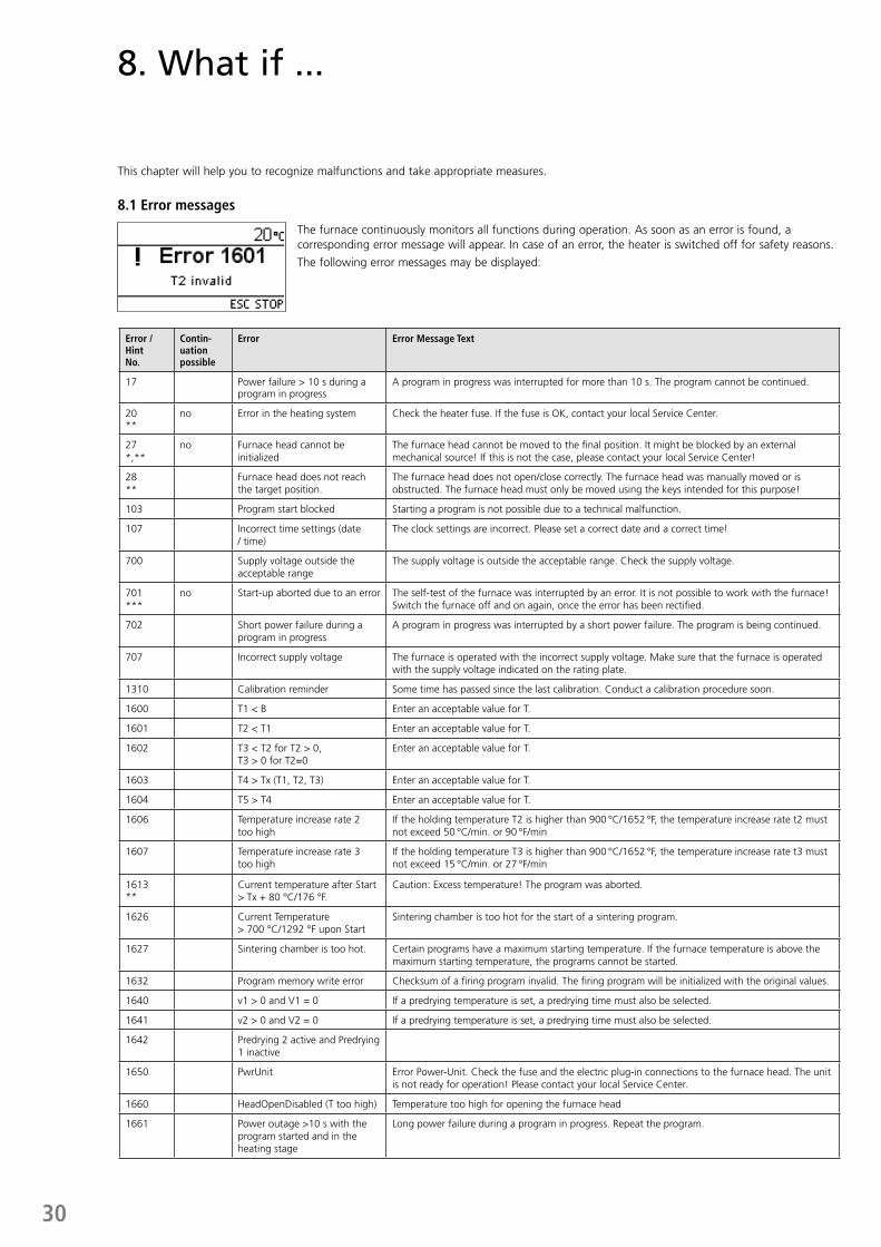
The furnace continuously monitors all functions during operation. As soon as an error is found, a corresponding error message will appear. In case of an error, the heater is switched off for safety reasons.
The following error messages may be displayed:
Error /HintNo.
Contin-uation possible
Error Error Message Text
17 Power failure > 10 s during a program in progress
A program in progress was interrupted for more than 10 s. The program cannot be continued.
20**
no Error in the heating system Check the heater fuse. If the fuse is OK, contact your local Service Center.
27 *,**
no Furnace head cannot be initialized
The furnace head cannot be moved to the final position. It might be blocked by an external mechanical source! If this is not the case, please contact your local Service Center!
28 **
Furnace head does not reach the target position.
The furnace head does not open/close correctly. The furnace head was manually moved or is obstructed. The furnace head must only be moved using the keys intended for this purpose!
103 Program start blocked Starting a program is not possible due to a technical malfunction.
107 Incorrect time settings (date / time)
The clock settings are incorrect. Please set a correct date and a correct time!
700 Supply voltage outside the acceptable range
The supply voltage is outside the acceptable range. Check the supply voltage.
701***
no Start-up aborted due to an error The self-test of the furnace was interrupted by an error. It is not possible to work with the furnace! Switch the furnace off and on again, once the error has been rectified.
702 Short power failure during a program in progress
A program in progress was interrupted by a short power failure. The program is being continued.
707 Incorrect supply voltage The furnace is operated with the incorrect supply voltage. Make sure that the furnace is operated with the supply voltage indicated on the rating plate.
1310 Calibration reminder Some time has passed since the last calibration. Conduct a calibration procedure soon.
1600 T1 < B Enter an acceptable value for T.
1601 T2 < T1 Enter an acceptable value for T.
1602 T3 < T2 for T2 > 0, T3 > 0 for T2=0
Enter an acceptable value for T.
1603 T4 > Tx (T1, T2, T3) Enter an acceptable value for T.
1604 T5 > T4 Enter an acceptable value for T.
1606 Temperature increase rate 2 too high
If the holding temperature T2 is higher than 900 °C/1652 °F, the temperature increase rate t2 must not exceed 50 °C/min. or 90 °F/min
1607 Temperature increase rate 3 too high
If the holding temperature T3 is higher than 900 °C/1652 °F, the temperature increase rate t3 must not exceed 15 °C/min. or 27 °F/min
1613**
Current temperature after Start > Tx + 80 °C/176 °F.
Caution: Excess temperature! The program was aborted.
1626 Current Temperature > 700 °C/1292 °F upon Start
Sintering chamber is too hot for the start of a sintering program.
1627 Sintering chamber is too hot. Certain programs have a maximum starting temperature. If the furnace temperature is above the maximum starting temperature, the programs cannot be started.
1632 Program memory write error Checksum of a firing program invalid. The firing program will be initialized with the original values.
1640 v1 > 0 and V1 = 0 If a predrying temperature is set, a predrying time must also be selected.
1641 v2 > 0 and V2 = 0 If a predrying temperature is set, a predrying time must also be selected.
1642 Predrying 2 active and Predrying 1 inactive
1650 PwrUnit Error Power-Unit. Check the fuse and the electric plug-in connections to the furnace head. The unit is not ready for operation! Please contact your local Service Center.
1660 HeadOpenDisabled (T too high) Temperature too high for opening the furnace head
1661 Power outage >10 s with the program started and in the heating stage
Long power failure during a program in progress. Repeat the program.
31
8.2 Technical malfunctions
These malfunctions may occur without an error message being displayed:
Error Double Check Action
Indication on display is incomplete Activate the display test program and contact the
Ivoclar Vivadent After Sales Service.
Writing in the display is very hard to read Is the contrast properly set? Adjust contrast
Display is not illuminatedIs the furnace properly connected according to the Operating Instructions and switched on?
Correctly connect the furnace and switch it on.
Buzzer does not sound Is the buzzer switched off (Volume 0)? Select volume 1–5
Furnace head does not openWas the furnace head opened manually? Open the furnace head only by using the
corresponding keys. Switch the furnace off and on again.
Incorrect or illogical temperature indication
Is the thermocouple bent or fractured? Contact the Ivoclar Vivadent After Sales Service.
Is the thermocouple correctly connected? Correctly connect thermocouple.
Is the thermocouple plug defective? Contact the Ivoclar Vivadent After Sales Service.
Cracks in the insulation of the sintering chamber
Are the cracks small and insignificant (hairline cracks)?
Small cracks in the insulation are acceptable and do not negatively influence the furnace.
Are the cracks large or have parts broken off? Contact the Ivoclar Vivadent After Sales Service.
Damage of a heating element Is the heating element bent or fractured? Switch off the furnace and contact the Ivoclar
Vivadent After Sales Service
Damage of the thermocouple Is the thermocouple damaged or fractured? Contact the Ivoclar Vivadent After Sales Service.
8.3 Repair
Repairs may only be carried out by a certified Ivoclar Vivadent Service Centre. Please refer to the addresses on the last page of these Operating Instructions.
If repairs during the warranty period are not carried out by a certified Ivoclar Vivadent After Sales Service Center, the warranty will expire immediately. Please also refer to the corresponding warranty regulations.
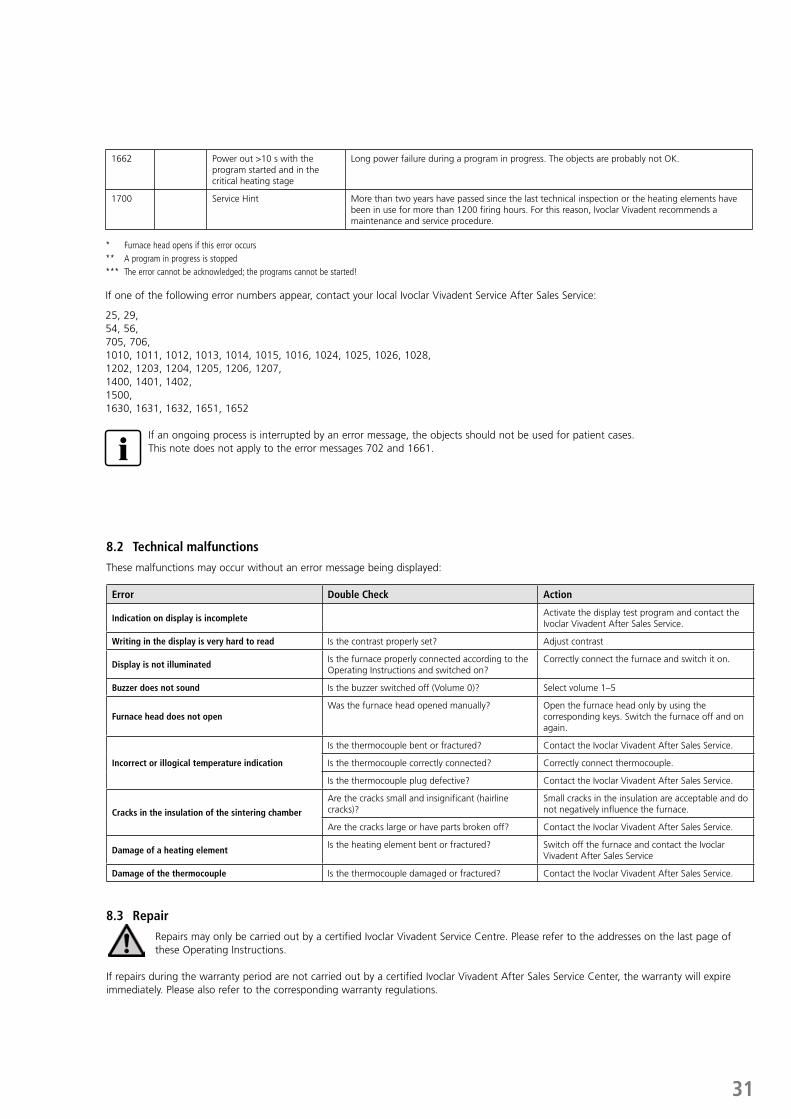
1662 Power out >10 s with the program started and in the critical heating stage
Long power failure during a program in progress. The objects are probably not OK.
1700 Service Hint More than two years have passed since the last technical inspection or the heating elements have been in use for more than 1200 firing hours. For this reason, Ivoclar Vivadent recommends a maintenance and service procedure.
* Furnace head opens if this error occurs ** A program in progress is stopped *** The error cannot be acknowledged; the programs cannot be started!
If one of the following error numbers appear, contact your local Ivoclar Vivadent Service After Sales Service:
25, 29, 54, 56, 705, 706, 1010, 1011, 1012, 1013, 1014, 1015, 1016, 1024, 1025, 1026, 1028, 1202, 1203, 1204, 1205, 1206, 1207,1400, 1401, 1402,1500,1630, 1631, 1632, 1651, 1652
If an ongoing process is interrupted by an error message, the objects should not be used for patient cases. This note does not apply to the error messages 702 and 1661.
32
9. Product Specifications
9.1 Delivery forms
– Programat CS4 – Power cord– Sintering Furnace Temperature Checking Set Starter Kit– Operating Instructions – Sinter tray – Sinter tray fork– IPS e.max Speed Crystallization Tray– USB download cable– var. accessories
9.2 Technical data
Power supply 118–240 V / 50–60 Hz
Overvoltage category II
Contamination level 2
Acceptable voltage fluctuations ± 10 %
Max. power consumption 16 A at 118 V8 A at 240 V
Electric fuses 250 V / T16 A high breaking (heating circuit)
Dimensions of electric fuses 250 V / T16 A high breaking (heating circuit)
Dimensions of the closed furnace Depth: 430 mm Width: 310 mm / 390 mm (with cooling tray)Height: 570 mm
Usable size of the firing chamber Diameter: 80 mmHeight: 80 mm
Max. firing temperature 1600 °C/2912 °F
Weight Furnace base: 10 kgFurnace head: 17 kg
Safety notes The sinter furnace complies with the following standards:– IEC 61010-1: 2010 – EN 61010-1: 2010– UL 61010-1: 2012-2015– CSA 61010-1: 2012 – 2015– IEC 61010-2-010: 2014– EN 61010-2-010: 2014– UL 61010-2-010: 2015– CSA 61010-2-010: 2015Radio protection / electromagnetic compatibility EMC tested
9.3 Acceptable operating conditions
– Acceptable ambient temperature range: +5 °C to +40 °C (+41 °F to +104 °F)– Acceptable humidity range: Relative humidity 80% for temperatures up to 31 °C/88 °F
gradually decreasing to 50% relative humidity at 40 °C/104 °F, condensation excluded.
– Acceptable ambient pressure: The furnace is tested for use at altitudes of up to 2000 m above sea level.
9.4 Acceptable transportation and storage conditions
– Acceptable temperature range: –20 °C to +65 °C (–4 °F to 149 °F)– Acceptable humidity range: Max. 80% relative humidity– Acceptable ambient pressure: 500 mbar to 1060 mbar
Use only the original packaging together with the corresponding foam material for shipping purposes.

33
10. Appendix
10.1 Program table
A program table is enclosed in these Operating Instructions. Should this not be the case, please contact the Ivoclar Vivadent Service Center.
Important information The current program tables are also available at: www.ivoclarvivadent.com
The program tables can be downloaded from the Internet as PDF files. Please note, that the version of the program table should correspond to the software version which is used on your furnace.


Ivoclar Vivadent AGBendererstrasse 29494 SchaanLiechtensteinTel. +423 235 35 35Fax +423 235 33 60www.ivoclarvivadent.com
Ivoclar Vivadent Pty. Ltd. 1 – 5 Overseas DriveP.O. Box 367Noble Park, Vic. 3174AustraliaTel. +61 3 9795 9599Fax +61 3 9795 9645www.ivoclarvivadent.com.au
Ivoclar Vivadent GmbHTech Gate ViennaDonau-City-Strasse 11220 WienAustria Tel. +43 1 263 191 10Fax: +43 1 263 191 111www.ivoclarvivadent.at
Ivoclar Vivadent Ltda.Alameda Caiapós, 723Centro Empresarial TamboréCEP 06460-110 Barueri – SPBrazilTel. +55 11 2424 7400Fax +55 11 3466 0840www.ivoclarvivadent.com.br
Ivoclar Vivadent Inc.1-6600 Dixie RoadMississauga, OntarioL5T 2Y2CanadaTel. +1 905 670 8499Fax +1 905 670 3102www.ivoclarvivadent.us
Ivoclar Vivadent Shanghai Trading Co., Ltd.2/F Building 1, 881 Wuding Road, Jing An District 200040 Shanghai ChinaTel. +86 21 6032 1657Fax +86 21 6176 0968www.ivoclarvivadent.com
Ivoclar Vivadent Marketing Ltd.Calle 134 No. 7-B-83, Of. 520BogotáColombiaTel. +57 1 627 3399Fax +57 1 633 1663www.ivoclarvivadent.co
Ivoclar Vivadent SASB.P. 11874410 Saint-JoriozFranceTel. +33 4 50 88 64 00Fax +33 4 50 68 91 52www.ivoclarvivadent.fr
Ivoclar Vivadent GmbH Dr. Adolf-Schneider-Str. 273479 Ellwangen, JagstGermanyTel. +49 7961 889 0Fax +49 7961 6326www.ivoclarvivadent.de
Ivoclar Vivadent Marketing (India) Pvt. Ltd. 503/504 Raheja Plaza 15 B Shah Industrial Estate Veera Desai Road, Andheri (West) Mumbai, 400 053 IndiaTel. +91 22 2673 0302 Fax +91 22 2673 0301www.ivoclarvivadent.in
Ivoclar Vivadent Marketing Ltd.The IconHorizon Broadway BSDBlock M5 No. 1Kecamatan Cisauk Kelurahan Sampora15345 Tangerang Selatan – BantenIndonesiaTel. +62 21 3003 2932Fax +62 21 3003 2934www.ivoclarvivadent.com
Ivoclar Vivadent s.r.l. Via Isonzo 67/6940033 Casalecchio di Reno (BO)ItalyTel. +39 051 6113555Fax +39 051 6113565www.ivoclarvivadent.it
Ivoclar Vivadent K.K.1-28-24-4F HongoBunkyo-ku Tokyo 113-0033JapanTel. +81 3 6903 3535Fax +81 3 5844 3657www.ivoclarvivadent.jp
Ivoclar Vivadent Ltd.12F W-Tower54 Seocho-daero 77-gil, Seocho-guSeoul, 06611Republic of KoreaTel. +82 2 536 0714Fax +82 2 596 0155www.ivoclarvivadent.co.kr
Ivoclar Vivadent S.A. de C.V.Calzada de Tlalpan 564,Col Moderna, Del Benito Juárez03810 México, D.F.MéxicoTel. +52 (55) 50 62 10 00Fax +52 (55) 50 62 10 29www.ivoclarvivadent.com.mx
Ivoclar Vivadent BVDe Fruittuinen 322132 NZ HoofddorpNetherlandsTel. +31 23 529 3791Fax +31 23 555 4504www.ivoclarvivadent.com
Ivoclar Vivadent Ltd.12 Omega St, RosedalePO Box 303011 North HarbourAuckland 0751New ZealandTel. +64 9 914 9999Fax +64 9 914 9990www.ivoclarvivadent.co.nz
Ivoclar Vivadent Polska Sp. z o.o.ul. Jana Pawla II 7800-175 WarszawaPolandTel. +48 22 635 5496Fax +48 22 635 5469www.ivoclarvivadent.pl
Ivoclar Vivadent LLC Prospekt Andropova 18 korp. 6/ office 10-06 115432 Moscow Russia Tel. +7 499 418 0300 Fax +7 499 418 0310 www.ivoclarvivadent.ru
Ivoclar Vivadent Marketing Ltd.Qlaya Main St.Siricon Building No.14, 2nd FloorOffice No. 204P.O. Box 300146Riyadh 11372Saudi ArabiaTel. +966 11 293 8345Fax +966 11 293 8344www.ivoclarvivadent.com
Ivoclar Vivadent S.L.U.Carretera de Fuencarral nº24Portal 1 – Planta Baja28108-Alcobendas (Madrid)SpainTel. +34 91 375 78 20Fax +34 91 375 78 38www.ivoclarvivadent.es
Ivoclar Vivadent ABDalvägen 14169 56 SolnaSwedenTel. +46 8 514 939 30Fax +46 8 514 939 40www.ivoclarvivadent.se
Ivoclar Vivadent Liaison Office: Tesvikiye Mahallesi Sakayik SokakNisantas’ Plaza No:38/2Kat:5 Daire:24 34021 Sisli – Istanbul Turkey Tel. +90 212 343 0802 Fax +90 212 343 0842www.ivoclarvivadent.com
Ivoclar Vivadent LimitedCompass BuildingFeldspar CloseWarrens Business ParkEnderbyLeicester LE19 4SDUnited KingdomTel. +44 116 284 7880Fax +44 116 284 7881www.ivoclarvivadent.co.uk
Ivoclar Vivadent, Inc. 175 Pineview DriveAmherst, N.Y. 14228USATel. +1 800 533 6825Fax +1 716 691 2285www.ivoclarvivadent.us
Ivoclar Vivadent – worldwide
Version: 1 Date information prepared: 2017-03
The apparatus has been developed solely for use in dentistry. Start-up and operation should be carried out strictly according to the Operating Instructions. Liability cannot be accepted for damages resulting from misuse or failure to observe the Instructions. The user is solely responsible for testing the apparatus for its suitability for any purpose not explicitly stated in the Instructions. Descriptions and data constitute no warranty of attributes and are not binding.
Printed in Austria © Ivoclar Vivadent AG, Schaan/Liechtenstein 689801/EN