Embed Size (px)
Citation preview

Form No. 08158SL Rev D
ProForce® Debris Blower
Original Instructions (EN)

Revision History Revision Date Description
-- 2008 Initial Issue.
A 2009 Updated Engine chapter.
B 2011 Updated Electrical chapter.
C 2014 Updated Engine chapter.
D 02/2018 Added revision history.
© THE TORO COMPANY 2018 This document and all information contained herein is the sole property of The Toro Company (and/or its affiliated companies). No intellectual property rights are granted by the delivery of this document or the disclosure of its content. This document shall not be reproduced by a third party without the express written consent of The Toro Company (and/or the appropriate affiliated company).

Reader Comments
The Toro Company Technical Assistance Center maintains a continuous effort to improve the quality and usefulness of its publications. To do this effectively, we encourage user feedback. Please comment on the completeness, accuracy, organization, usability, and readability of this manual by an e-mail to [email protected] or Mail to: Technical Publication Manager, Commercial The Toro Company 8111 Lyndale Avenue South Bloomington, MN 55420-1196 Phone: +1 952-887-8495

NOTES _

Part No. 08158SL (Rev. D)
Service Manual
ProForceR Debris Blower
Preface
The purpose of this publication is to provide the servicetechnician with information for troubleshooting, testingand repair of major systems and components on theProForce Debris Blower.
REFER TO THE OPERATOR’S MANUALS FOR OP-ERATING, MAINTENANCE AND ADJUSTMENTINSTRUCTIONS. Space is provided in Chapter 2 of thisbook to insert the Operator’s Manuals and Parts Cata-logs for your machine. Additional copies of the Opera-tor’s Manual are available on the Internet atwww.Toro.com.
The ToroCompany reserves the right to changeproductspecifications or this publication without notice.
This safety symbol means DANGER, WARNING,or CAUTION, PERSONAL SAFETY INSTRUC-TION. When you see this symbol, carefully readthe instructions that follow. Failure to obey theinstructions may result in personal injury.
NOTE: ANOTE will give general information about thecorrect operation, maintenance, service, testing or re-pair of the machine.
IMPORTANT: The IMPORTANT notice will give im-portant instructionswhichmust be followed to pre-vent damage to systems or components on themachine.
E The Toro Company -- 2008, 2009, 2011, 2014, 2018

ProForce Debris Blower
This page is intentionally blank.

Rev. CProForce Debris Blower
Table Of Contents
Chapter 1 - Safety
Safety Instructions 1 - 2. . . . . . . . . . . . . . . . . . . . . . . . . .Securing ProForce Debris Blower to Tow Vehicle 1 - 5Jacking Instructions 1 - 5. . . . . . . . . . . . . . . . . . . . . . . . .Safety and Instruction Decals 1 - 6. . . . . . . . . . . . . . . .
Chapter 2 - Product Records and Maintenance
Product Records 2 - 1. . . . . . . . . . . . . . . . . . . . . . . . . . .Maintenance 2 - 1. . . . . . . . . . . . . . . . . . . . . . . . . . . . . . .Equivalents and Conversions 2 - 2. . . . . . . . . . . . . . . .Torque Specifications 2 - 3. . . . . . . . . . . . . . . . . . . . . . .
Chapter 3 - Engine
Specifications 3 - 2. . . . . . . . . . . . . . . . . . . . . . . . . . . . . .General Information 3 - 3. . . . . . . . . . . . . . . . . . . . . . . .Service and Repairs 3 - 5. . . . . . . . . . . . . . . . . . . . . . . .KOHLER COMMAND ENGINE SERVICE MANUAL
Chapter 4 - Electrical System
General Information 4 - 2. . . . . . . . . . . . . . . . . . . . . . . .Electrical Diagrams 4 - 2. . . . . . . . . . . . . . . . . . . . . . . . .Special Tools 4 - 3. . . . . . . . . . . . . . . . . . . . . . . . . . . . . .Troubleshooting 4 - 5. . . . . . . . . . . . . . . . . . . . . . . . . . . .Electrical System Quick Checks 4 - 8. . . . . . . . . . . . . .Component Testing 4 - 9. . . . . . . . . . . . . . . . . . . . . . . . .Service and Repairs 4 - 20. . . . . . . . . . . . . . . . . . . . . . .
Chapter 5 - Blower Assembly
General Information 5 - 2. . . . . . . . . . . . . . . . . . . . . . . .Special Tools 5 - 3. . . . . . . . . . . . . . . . . . . . . . . . . . . . . .Service and Repairs 5 - 4. . . . . . . . . . . . . . . . . . . . . . . .
Chapter 6 - Chassis
Specifications 6 - 2. . . . . . . . . . . . . . . . . . . . . . . . . . . . . .General Information 6 - 3. . . . . . . . . . . . . . . . . . . . . . . .Service and Repairs 6 - 4. . . . . . . . . . . . . . . . . . . . . . . .
Chapter 7 - Electrical Diagrams
Electrical Schematics 7 - 3. . . . . . . . . . . . . . . . . . . . . . .Engine Electrical Diagrams 7 - 6. . . . . . . . . . . . . . . . . .Circuit Drawings 7 - 8. . . . . . . . . . . . . . . . . . . . . . . . . . . .Wire Harness Drawings 7 - 14. . . . . . . . . . . . . . . . . . . .
Safety
ProductRecords
andMaintenance
Engine
Electrical
Blower
System
Chassis
Assem
bly
Electrical
Diagrams

ProForce Debris Blower
This page is intentionally blank.

ProForce Debris Blower Page 1 -- 1 Safety
Chapter 1
Safety
Table of Contents
SAFETY INSTRUCTIONS 2. . . . . . . . . . . . . . . . . . . . . .Before Operating 2. . . . . . . . . . . . . . . . . . . . . . . . . . . .While Operating 3. . . . . . . . . . . . . . . . . . . . . . . . . . . . .Maintenance and Service 4. . . . . . . . . . . . . . . . . . . .
SECURING PROFORCE DEBRIS BLOWER TOTOW VEHICLE 5. . . . . . . . . . . . . . . . . . . . . . . . . . . . . .
JACKING INSTRUCTIONS 5. . . . . . . . . . . . . . . . . . . . .SAFETY AND INSTRUCTION DECALS 6. . . . . . . . . .
Safety

Rev. A ProForce Debris BlowerPage 1 -- 2Safety
Safety Instructions
The ProForce Debris Blower is designed and tested tooffer safe service when operated and maintained prop-erly. Although hazard control and accident preventionpartially are dependent upon the design and configura-tion of the machine, these factors are also dependentupon the awareness, concern and proper training of thepersonnel involved in the operation, transport, mainte-nance and storage of the machine. Improper use ormaintenance of the machine can result in injury ordeath. To reduce thepotential for injury or death, complywith the following safety instructions.
WARNING
To reduce the potential for injuryor death, com-ply with the following safety instructions.
Before Operating
1. Read and understand the contents of theOperator’sManual before starting and operating the ProForce De-bris Blower. Become familiar with the controls and knowhow to stop themachinequickly. Additional copies of theOperator’s Manual are available on the internet atwww.Toro.com.
2. Keep all shields, safety devices and decals in place.If a shield, safety device or decal is defective, illegibleor damaged, repair or replace it before operating themachine.
3. Make sure that the tow vehicle is carefully selectedto assure the best performance and safe operation ofthe ProForce Debris Blower.
4. Make sure that operator is familiar with safe tow ve-hicle operation.
5. Tightenany loosenuts, bolts, screws or other fasten-ers to ensure machine is in safe operating condition.
6. Make sure that the ProForce Debris Blower is prop-erly attached to tow vehicle.

ProForce Debris Blower Page 1 -- 3 Safety
While Operating
1. Operator should be on the tow vehicle when startingthe engine and when operating the ProForce DebrisBlower. Stay away from the blower when it is engaged.
2. Before starting the engine on the tow vehicle, referto towvehicleOperator’sManual for safe starting proce-dures.
3. Do not run engine of ProForce Debris Blower or towvehicle in a confined area without adequate ventilation.Exhaust fumes are hazardous and could possibly bedeadly.
4. Be aware of the blower nozzle direction and do notpoint it at anyone. Keep away from the nozzle openingduring machine operation.
5. Do not touchengine or exhaust systemwhile theDe-bris Blower engine is running or soon after it is stopped.These areas could be hot enough to cause burns.
6. If abnormal vibration is detected, shut off blower andstop tow vehicle immediately. Determine source ofvibration and correct problem(s) before resuming theuse of blower.
7. While operating, the combination of the tow vehicleand the ProForce Debris Blower may exceed noise lev-els of 85dB(A) at the operator position. Hearing protec-tion is recommended for prolonged exposure to reducethe potential of permanent hearing damage.
8. Before leaving the operator’s position of the tow ve-hicle:
A. Park on level surface and stop ProForce DebrisBlower engine. Make sure that all machine motionhas stopped.
B. Ensure that tow vehicle transmission or tractionlever is in neutral, set parking brake, stop engineandremove key from ignition switch.
C. Wait for all moving parts to stop before leavingthe tow vehicle.
D. If blower use is complete, turn ProForce DebrisBlower ignition switch OFF and remove key fromswitch.
Safety

Rev. C ProForce Debris BlowerPage 1 -- 4Safety
Maintenance and Service
1. Before servicing or making adjustments to ProForceDebris Blower, position ProForce Debris Blower on alevel surface and stop blower engine. If blower is at-tached to tow vehicle, apply tow vehicle parking brake,stop engine and remove key from the ignition switch.Also, turn blower ignition switch OFF and remove keyfrom switch.
2. To prevent unexpected machine operation, discon-nect battery before performing any Debris Blower ser-vice. Disconnect negative battery cable first andpositive cable last. If battery voltage is required for trou-bleshooting or test procedures, temporarily connect thebattery. Reconnect positive battery cable first andnega-tive cable last.
3. Make sure machine is in safe operating condition bykeeping all nuts, bolts, screws and other fasteners tight.
4. Use care when checking or servicing the blower:wear gloves and use caution.
5. Before disconnecting ProForce Debris Blower fromtow vehicle, park blower on a hard, level surface andchock blower wheels to prevent machine movement.
6. To reduce potential fire hazard, keep engine areafree of excessive grease, grass, leaves and dirt.
7. If enginemust be running to performmaintenanceorto make an adjustment, keep hands, feet, clothing andother parts of the body away from moving parts on theDebris Blower. Keep bystanders away.
8. Do not overspeed the engine by changing governorsetting. Toassure safety andaccuracy, checkmaximumengine speed with a tachometer.
9. Shut Debris Blower engine off before checking oradding oil to the crankcase.
10.Battery acid is poisonous and can cause burns.Avoid contact with skin, eyes and clothing. Protect yourface, eyes and clothing when working with a battery.
11.Battery gases can explode. Keep cigarettes, sparksand flames away from the battery.
12.After servicing the ProForce Debris Blower, be surethat all guards and covers are properly installed.
13.When changing tires or performing other service,use correct supports, hoists and jacks. Make sure ma-chine is parked on a solid level surface such as a con-crete floor. Always chock or block wheels. Use suitablejack stands to support the raised machine. If the ma-chine is not properly supported by suitable jack stands,the machine may move or fall, which may result in per-sonal injury (see Jacking Instructions in this chapter).
14.If welding on the machine is necessary, disconnectthe negative battery cable and the wire harness con-nector from the wireless control module to prevent elec-trical system damage.
15.If major repairs are ever needed or assistance is de-sired, contact an Authorized Toro Distributor.
16.Engine oil, engine and remote batteries are pollut-ants to the environment. Dispose of these according toyour state and local regulations.
17.At the time of manufacture, the machine conformedto all applicable safety standards. To assure optimumperformance and continued safety certification of themachine, use genuine Toro replacement parts and ac-cessories. Replacement parts and accessories madeby other manufacturers may result in non-conformancewith the safety standards, and the warranty may bevoided.

ProForce Debris Blower Page 1 -- 5 Safety
Securing ProForce Debris Blower to Tow Vehicle
While operating or servicing the ProForce Debris Blow-er, make sure that blower is properly secured to tow ve-hicle (Fig. 1). Refer to your Operator’s Manual for thecorrect procedure for attaching blower to tow vehicle.
1. Tow vehicle hitch2. Hitch pin
3. Hairpin clipFigure 1
3
21
Jacking Instructions
CAUTIONWhen changing tires or performing other ser-vice, use suitable hoists and jacks to supportthe ProForce Debris Blower. Make sure ma-chine is parked on a solid level surface such asa concrete floor. Always chock or blockwheels.Use suitable jack stands to support the raisedmachine. If the machine is not properly sup-ported by jack stands, the machine may moveor fall, which may result in personal injury.
1. Position ProForce Debris Blower on a level surfacewith blower attached to tow vehicle. Engage tow vehicleparking brake, stop engine and remove key from theignition switch. Make sure that blower engine is off.Chock blower wheels to prevent the machine from mo-ving.
2. Position jack securely under the main frame of theblower (Fig. 2). Do not use the axle as a jacking point.
3. Carefully jack machine off the ground.
4. Position jack stands under themain frame to supportthe ProForce Debris Blower.
1. Wheel 2. Frame jacking point
Figure 2
2
1
Safety

ProForce Debris BlowerPage 1 -- 6Safety
Safety and Instruction Decals
Numerous safety and instruction decals are affixed tothe ProForceDebris Blower. If any decal becomes illeg-ible or damaged, install a new decal. Part numbers forreplacement decals are listed in your Parts Catalog. Or-der replacement decals from your Authorized Toro Dis-tributor.

ProForce Debris Blower Page 2 -- 1 Product Records and Maintenance
Chapter 2
Product Records and Maintenance
Table of Contents
PRODUCT RECORDS 1. . . . . . . . . . . . . . . . . . . . . . . . .MAINTENANCE 1. . . . . . . . . . . . . . . . . . . . . . . . . . . . . . .EQUIVALENTS AND CONVERSIONS 2. . . . . . . . . . .Decimal and Millimeter Equivalents 2. . . . . . . . . . . .U.S. to Metric Conversions 2. . . . . . . . . . . . . . . . . . .
TORQUE SPECIFICATIONS 3. . . . . . . . . . . . . . . . . . . .Fastener Identification 3. . . . . . . . . . . . . . . . . . . . . . .Standard Torque for Dry, Zinc Plated andSteel Fasteners (Inch Series) 4. . . . . . . . . . . . . . .
Standard Torque for Dry, Zinc Plated andSteel Fasteners (Metric Fasteners) 5. . . . . . . . . . .
Other Torque Specifications 6. . . . . . . . . . . . . . . . . .Conversion Factors 6. . . . . . . . . . . . . . . . . . . . . . . . . .
Product Records
Insert Operator’s Manual and Parts Catalog for yourProForce Debris Blower at the end of this chapter. Addi-tionally, if any optional equipment or accessories havebeen installed to your blower, insert the Installation In-structions, Operator’s Manuals and Parts Catalogs forthose options at the end of this chapter.
Maintenance
Maintenance procedures and recommended service in-tervals for the ProForce Debris Blower are covered inthe Operator’s Manual. Refer to that publication whenperforming regular equipment maintenance.
ProductRecords
andMaintenance

0.09375
ProForce Debris BlowerPage 2 -- 2Product Records and Maintenance
Equivalents and Conversions

ProForce Debris Blower Page 2 -- 3 Product Records and Maintenance
Torque Specifications
Recommended fastener torque values are listed in thefollowing tables. For critical applications, as determinedby Toro, either the recommended torque or a torque thatis unique to the application is clearly identified and spe-cified in this Service Manual.
These Torque Specifications for the installation andtightening of fasteners shall apply to all fasteners whichdo not have a specific requirement identified in this Ser-vice Manual. The following factors shall be consideredwhen applying torque: cleanliness of the fastener, useof a thread sealant (e.g. Loctite), degree of lubricationon the fastener, presence of a prevailing torque feature,hardness of the surface underneath the fastener’s heador similar condition which affects the installation.
As noted in the following tables, torque values should bereduced by 25% for lubricated fasteners to achievethe similar stress as a dry fastener. Torque values mayalso have to be reduced when the fastener is threadedinto aluminum or brass. The specific torque valueshould be determined based on the aluminum or brassmaterial strength, fastener size, length of thread en-gagement, etc.
The standard method of verifying torque shall be per-formed by marking a line on the fastener (head or nut)and mating part, then back off fastener 1/4 of a turn.Measure the torque required to tighten the fastener untilthe lines match up.
Fastener Identification
Figure 1
Grade 1 Grade 5 Grade 8
Inch Series Bolts and Screws
Figure 2
Class 8.8 Class 10.9
Metric Bolts and Screws
ProductRecords
andMaintenance

ProForce Debris BlowerPage 2 -- 4Product Records and Maintenance
Standard Torque for Dry, Zinc Plated and Steel Fasteners (Inch Series)
Thread SizeGrade 1, 5 &8 with ThinHeight Nuts
SAE Grade 1 Bolts, Screws, Studs &Sems with Regular Height Nuts
(SAE J995 Grade 2 or Stronger Nuts)
SAE Grade 5 Bolts, Screws, Studs &Sems with Regular Height Nuts
(SAE J995 Grade 2 or Stronger Nuts)
SAE Grade 8 Bolts, Screws, Studs &Sems with Regular Height Nuts
(SAE J995 Grade 5 or Stronger Nuts)
in--lb in--lb N--cm in--lb N--cm in--lb N--cm
# 6 -- 32 UNC10 + 2 13 + 2 147 + 23
15 + 2 170 + 20 23 + 2 260 + 20
# 6 -- 40 UNF10 + 2 13 + 2 147 + 23
17 + 2 190 + 20 25 + 2 280 + 20
# 8 -- 32 UNC13 + 2 25 + 5 282 + 30
29 + 3 330 + 30 41 + 4 460 + 45
# 8 -- 36 UNF13 + 2 25 + 5 282 + 30
31 + 3 350 + 30 43 + 4 485 + 45
# 10 -- 24 UNC18 + 2 30 + 5 339 + 56
42 + 4 475 + 45 60 + 6 675 + 70
# 10 -- 32 UNF18 + 2 30 + 5 339 + 56
48 + 4 540 + 45 68 + 6 765 + 70
1/4 -- 20 UNC 48 + 7 53 + 7 599 + 79 100 + 10 1125 + 100 140 + 15 1580 + 170
1/4 -- 28 UNF 53 + 7 65 + 10 734 + 113 115 + 10 1300 + 100 160 + 15 1800 + 170
5/16 -- 18 UNC 115 + 15 105 + 17 1186 + 169 200 + 25 2250 + 280 300 + 30 3390 + 340
5/16 -- 24 UNF 138 + 17 128 + 17 1446 + 192 225 + 25 2540 + 280 325 + 30 3670 + 340
ft--lb ft--lb N--m ft--lb N--m ft--lb N--m
3/8 -- 16 UNC 16 + 2 16 + 2 22 + 3 30 + 3 41 + 4 43 + 4 58 + 5
3/8 -- 24 UNF 17 + 2 18 + 2 24 + 3 35 + 3 47 + 4 50 + 4 68 + 5
7/16 -- 14 UNC 27 + 3 27 + 3 37 + 4 50 + 5 68 + 7 70 + 7 95 + 9
7/16 -- 20 UNF 29 + 3 29 + 3 39 + 4 55 + 5 75 + 7 77 + 7 104 + 9
1/2 -- 13 UNC 30 + 3 48 + 7 65 + 9 75 + 8 102 + 11 105 + 10 142 + 14
1/2 -- 20 UNF 32 + 3 53 + 7 72 + 9 85 + 8 115 + 11 120 + 10 163 + 14
5/8 -- 11 UNC 65 + 10 88 + 12 119 + 16 150 + 15 203 + 20 210 + 20 285 + 27
5/8 -- 18 UNF 75 + 10 95 + 15 129 + 20 170 + 15 230 + 20 240 + 20 325 + 27
3/4 -- 10 UNC 93 + 12 140 + 20 190 + 27 265 + 25 359 + 34 375 + 35 508 + 47
3/4 -- 16 UNF 115 + 15 165 + 25 224 + 34 300 + 25 407 + 34 420 + 35 569 + 47
7/8 -- 9 UNC 140 + 20 225 + 25 305 + 34 430 + 45 583 + 61 600 + 60 813 + 81
7/8 -- 14 UNF 155 + 25 260 + 30 353 + 41 475 + 45 644 + 61 660 + 60 895 + 81
NOTE: Reduce torque values listed in the table aboveby 25% for lubricated fasteners. Lubricated fastenersare defined as threads coated with a lubricant such asoil, graphite or thread sealant such as Loctite.
NOTE: Torque values may have to be reduced wheninstalling fasteners into threaded aluminum or brass.The specific torque value should be determined basedon the fastener size, the aluminum or base materialstrength, length of thread engagement, etc.
NOTE: The nominal torque values listed above forGrade 5 and 8 fasteners are based on 75% of the mini-mum proof load specified in SAE J429. The tolerance isapproximately + 10% of the nominal torque value. Thinheight nuts include jam nuts.

ProForce Debris Blower Page 2 -- 5 Product Records and Maintenance
Standard Torque for Dry, Zinc Plated and Steel Fasteners (Metric Fasteners)
Thread SizeClass 8.8 Bolts, Screws and Studs with
Regular Height NutsClass 10.9 Bolts, Screws and Studs with
Regular Height NutsThread Size Regular Height Nuts(Class 8 or Stronger Nuts)
Regular Height Nuts(Class 10 or Stronger Nuts)
M5 X 0.8 57 + 5 in--lb 640 + 60 N--cm 78 + 7 in--lb 885 + 80 N--cm
M6 X 1.0 96 + 9 in--lb 1018 + 100 N--cm 133 + 13 in--lb 1500 + 150 N--cm
M8 X 1.25 19 + 2 ft--lb 26 + 3 N--m 27 + 2 ft--lb 36 + 3 N--m
M10 X 1.5 38 + 4 ft--lb 52 + 5 N--m 53 + 5 ft--lb 72 + 7 N--m
M12 X 1.75 66 + 7 ft--lb 90 + 10 N--m 92 + 9 ft--lb 125 + 12 N--m
M16 X 2.0 166 + 15 ft--lb 225 + 20 N--m 229 + 22 ft--lb 310 + 30 N--m
M20 X 2.5 325 + 33 ft--lb 440 + 45 N--m 450 + 37 ft--lb 610 + 50 N--m
NOTE: Reduce torque values listed in the table aboveby 25% for lubricated fasteners. Lubricated fastenersare defined as threads coated with a lubricant such asoil, graphite or thread sealant such as Loctite.
NOTE: Torque values may have to be reduced wheninstalling fasteners into threaded aluminum or brass.The specific torque value should be determined basedon the fastener size, the aluminum or base materialstrength, length of thread engagement, etc.
NOTE: The nominal torque values listed above arebased on 75% of the minimum proof load specified inSAEJ1199.The tolerance is approximately + 10%of thenominal torque value.
ProductRecords
andMaintenance

ProForce Debris BlowerPage 2 -- 6Product Records and Maintenance
Other Torque Specifications
SAE Grade 8 Steel Set Screws
Thread SizeRecommended Torque
Thread SizeSquare Head Hex Socket
1/4 -- 20 UNC 140 + 20 in--lb 73 + 12 in--lb
5/16 -- 18 UNC 215 + 35 in--lb 145 + 20 in--lb
3/8 -- 16 UNC 35 + 10 ft--lb 18 + 3 ft--lb
1/2 -- 13 UNC 75 + 15 ft--lb 50 + 10 ft--lb
Thread Cutting Screws(Zinc Plated Steel)
Type 1, Type 23 or Type F
Thread Size Baseline Torque*
No. 6 -- 32 UNC 20 + 5 in--lb
No. 8 -- 32 UNC 30 + 5 in--lb
No. 10 -- 24 UNC 38 + 7 in--lb
1/4 -- 20 UNC 85 + 15 in--lb
5/16 -- 18 UNC 110 + 20 in--lb
3/8 -- 16 UNC 200 + 100 in--lb
Wheel Bolts and Lug Nuts
Thread Size Recommended Torque**
7/16 -- 20 UNFGrade 5
65 + 10 ft--lb 88 + 14 N--m
1/2 -- 20 UNFGrade 5
80 + 10 ft--lb 108 + 14 N--m
M12 X 1.25Class 8.8
80 + 10 ft--lb 108 + 14 N--m
M12 X 1.5Class 8.8
80 + 10 ft--lb 108 + 14 N--m
** For steel wheels and non--lubricated fasteners.
Thread Cutting Screws(Zinc Plated Steel)
ThreadSize
Threads per InchBaseline Torque*Size
Type A Type BBaseline Torque*
No. 6 18 20 20 + 5 in--lb
No. 8 15 18 30 + 5 in--lb
No. 10 12 16 38 + 7 in--lb
No. 12 11 14 85 + 15 in--lb
*Hole size,material strength,material thickness& finishmust be considered when determining specific torquevalues. All torque values are based on non--lubricatedfasteners.
Conversion Factors
in--lb X 11.2985 = N--cm N--cm X 0.08851 = in--lbft--lb X 1.3558 = N--m N--m X 0.7376 = ft--lb

Rev. CProForce Debris Blower Page 3 - 1 Engine
Chapter 3
Engine
Table of Contents
SPECIFICATIONS 2. . . . . . . . . . . . . . . . . . . . . . . . . . . .GENERAL INFORMATION 3. . . . . . . . . . . . . . . . . . . . .Operator’s Manual 3. . . . . . . . . . . . . . . . . . . . . . . . . .Electrical Power 3. . . . . . . . . . . . . . . . . . . . . . . . . . . . .
SERVICE AND REPAIRS 5. . . . . . . . . . . . . . . . . . . . . .Engine Cooling System 5. . . . . . . . . . . . . . . . . . . . . .Fuel Tank 6. . . . . . . . . . . . . . . . . . . . . . . . . . . . . . . . . .Engine 8. . . . . . . . . . . . . . . . . . . . . . . . . . . . . . . . . . . . .Engine Removal 9. . . . . . . . . . . . . . . . . . . . . . . . . . .Engine Installation 10. . . . . . . . . . . . . . . . . . . . . . . .
Fuel Evaporative Control System (Serial NumberAbove 310000000) 12. . . . . . . . . . . . . . . . . . . . . . .
KOHLER COMMAND ENGINE SERVICE MANUAL
Engine

ProForce Debris BlowerPage 3 -- 2Engine
Specifications
Item Description
Make / Designation Kohler, 4--cycle, V--Twin cylinder,OHV, air cooled, Model CH740S
Bore x Stroke 3.27 in x 2.64 in (83 mm x 67 mm)
Total Displacement 44 in3 (725 cc)
Compression Ratio 9.0:1
Governor Electronic
Low Idle Speed (no load) 1800 + 100 RPM
High Idle Speed (no load) 3450 + 100 RPM
Carburetor Float feed, fixed main jet, solenoid fuel shut--off
Fuel Unleaded, regular grade gasoline
Fuel Pump Mechanical
Fuel Tank Capacity 5 U.S. gal (18.9 l)
Air Cleaner Dual element
Lubrication System Pressure lubrication with oil cooler
Crankcase Oil Capacity 2.0 U.S. qt (1.9 l)
Engine Oil See Operator’s Manual
Ignition System Flywheel magneto, twin electronic armatures with ignition advance
Spark Plug Champion RC12YC (resister style)
Spark Plug Gap 0.030 in (0.76 mm)
Starter 12 VDC, solenoid shift
Alternator 12 VDC / 15 Amps
Dry Weight 94 lbs (43 kg)

Rev. CProForce Debris Blower Page 3 - 3 Engine
General Information
This Chapter gives information about specifications,maintenance, troubleshooting, testing and repair of thegasoline engine used in the ProForce Debris Blower.
Most repairs and adjustments require tools which arecommonly available in many service shops. Specialtools are described in the KOHLER COMMAND EN-GINE SERVICE MANUAL that is included at the end ofthis Chapter. The use of some specialized test equip-
ment is explained. However, the cost of the test equip-ment and the specialized nature of some repairs maydictate that the work be done at an engine repair facility.
Service and repair parts for Kohler engines are suppliedthrough your local Toro distributor. Be prepared to pro-vide your distributor with the Toromodel and serial num-ber.
Operator’s Manual
The Operator’s Manual provides information regardingthe operation, general maintenance and maintenanceintervals for your ProForce Debris Blower machine. Re-fer to the Operator’s Manual for additional informationwhen servicing the machine.
Electrical Power
Electrical power to ProForce Debris Blower compo-nents is controlled by the Remote Control Module. Tomake sure that machine operation does not occur unex-pectedly, disconnect the negative battery cable from thebattery before performing any machine service (seeBattery Service in the Service and Repairs section ofChapter 4 - Electrical System).
Reattach the disconnected negative battery cable asthe last step in any repair. Secure cable with flange nut.Torque nut from 10 to 15 ft- lb (14 to 20 N-m).
Engine

ProForce Debris BlowerPage 3 -- 4Engine
This page is intentionally blank.

ProForce Debris Blower Page 3 -- 5 Engine
Service and Repairs
Engine Cooling System
To ensure proper engine cooling, make sure the grassscreen, cooling fins and other external surfaces of theengine are kept clean at all times.
IMPORTANT: The engine that powers the ProForceDebris Blower is air--cooled. Operating the enginewith dirty or plugged cooling fins or a plugged ordirty blower housing will result in engine overheat-ing and damage.
1. Park machine on a level surface. Make sure engineis OFF. Chock wheels to prevent machine frommoving.
2. To prevent unexpected machine operation, discon-nect the negative battery cable from the battery terminal(see Battery Service in the Service and Repairs sectionof Chapter 4 -- Electrical System). Position discon-nected negative cable away from the negative batteryterminal.
CAUTION
The engine may be hot. Allow engine to cool be-fore cleaning the engine cooling fins.
IMPORTANT: Never clean engine with pressurizedwater. Water could enter and contaminate the fuelsystem.
3. Clean cooling fins on both cylinder heads.
4. Clean grass screen and blower housing of dirt anddebris (Fig. 1).
5. If necessary remove blower housing from engine formore thorough engine cleaning.
IMPORTANT: Never operate engine without theblower housing installed. Overheating and enginedamage will result.
6. Make sure blower housing and/or engine cylindershrouds are installed to the engine if removed.
7. Connect negative battery cable to negative batteryterminal. Tighten nut that secures battery cable from 10to 15 ft--lb (14 to 20N--m). Make sure that battery coveris secured.
Figure 11. Cylinder head2. Grass screen
3. Blower housing
1
2 3
1
Engine
Rev. B ProForce Debris BlowerPage 3 -- 6Engine
Fuel Tank
Figure 21. Frame2. Foam strip (2 used)3. Fuel tank
4. Felt strip (2 used)5. Flange nut (4 used)6. Tank strap (2 used)
7. Fuel cap and gauge8. Worm clamp9. Fuel hose
FRONT
RIGHT
1
2
3
4
5
6
9
7
8SERIAL NUMBER BELOW 310000000 SHOWN
DANGER
Because gasoline is highly flammable, use cau-tion when storing or handling it. Do not smokewhile filling the fuel tank. Do not fill fuel tankwhile engine is running, hot, or whenmachine isin an enclosed area. Always fill fuel tank outsideand wipe up any spilled fuel before starting theengine. Store fuel in a clean, safety--approvedcontainer andkeepcap inplace.Usegasoline forthe engine only; not for any other purpose.
Check Fuel Lines and Connections
Check fuel lines and connections periodically as recom-mended in the Operator’s Manual. Check fuel lines fordeterioration, damage or leaking connections. Replacehoses, clamps and connections as necessary.
Drain and Clean Fuel Tank
Drain and clean the fuel tank periodically as recom-mended in theOperator’sManual. Also, drain and cleanthe fuel tank if the fuel system becomes contaminatedor if the machine is to be stored for an extended period.
To clean fuel tank, flush tank out with clean solvent.Make sure tank is free of all contaminates and debris.

Rev. BProForce Debris Blower Page 3 -- 7 Engine
Fuel Tank Removal (Figs. 2 and 4)
1. Parkmachineona level surfacewith theengineOFF.Chock wheels to prevent machine from moving.
2. To prevent unexpected machine operation, discon-nect the negative battery cable from the battery terminal(see Battery Service in the Service and Repairs sectionof Chapter 4 -- Electrical System). Position discon-nected negative cable away from the negative batteryterminal.
3. Remove fuel from the fuel tank and into a suitablecontainer.
4. Note routing of fuel hoses for installation purposes.Disconnect fuel hoses from fuel tank fittings. Plug fuelhoses to prevent leakage or contaminant entry.
5. Remove fuel tank from machine using Figure 2 or 4as a guide. Make sure to clean up any spilled fuel.
6. On machine with serial number above 310000000,remove components from fuel tank as needed usingFigure 5 as a guide.
Fuel Tank Installation (Figs. 2 and 4)
1. On machine with serial number above 310000000,install all removed components to fuel tank using Figure5 as a guide.
2. Install fuel tank to machine using Figure 2 or 4 as aguide.
3. Remove plugs placed in fuel hoses during fuel tankremoval. Connect fuel hoses to tank fittings and securewith hose clamps.
4. Add fuel to tank and check for any fuel leaks.
5. Connect negative battery cable to negative batteryterminal. Tighten nut that secures battery cable from 10to 15 ft--lb (14 to 20N--m). Make sure that battery coveris secured.
Figure 31. Engine blower housing2. Fuel filter
3. Fuel filter inlet
1
2
3
Figure 41. Fuel tank assembly2. Flange nut (4 used)
3. Tank strap (2 used)
1
2
3SERIAL NUMBER ABOVE310000000 SHOWN
Figure 51. Fuel tank2. Fuel tank cap3. Grommet4. Fuel gauge
5. Rollover valve6. Standpipe7. Grommet8. Bushing
2
3
6
1
5 4
8
7SERIALNUMBERABOVE
310000000
Engine

ProForce Debris BlowerPage 3 -- 8Engine
Engine
Figure 61. Frame2. Engine
3. Fuel tank4. Flange nut (4 used)
5. Flange head screw (4 used)6. Blower coupler assembly
FRONT
RIGHT
1
2
3
4
5
6
270 to 330 in--lb(31 to 37 N--m)

Rev. BProForce Debris Blower Page 3 -- 9 Engine
Engine Removal (Fig. 6)
1. Park machine on a level surface with the engine notrunning and the ignition key removed from the keyswitch. Chock wheels to prevent machine frommoving.
2. To prevent unexpected machine operation, discon-nect the negative battery cable from the battery terminal(see Battery Service in the Service and Repairs sectionof Chapter 4 -- Electrical System). Position discon-nected negative cable away from the negative batteryterminal.
CAUTION
The exhaust system may be hot. Avoid possibleburns: allowexhaust to coolbefore removing theengine.
3. If engine is to be disassembled, it may be easier todrain oil from engine before removing engine from ma-chine.
4. Label and disconnect wire harness connectors fromengine.
A. Disconnect positive battery cable and fusible linkfrom the starter motor B+ stud.
B. Disconnect wire harness blue wire from startermotor terminal.
C. Loosen and remove flange bolts that secure neg-ative battery cable andwire harness ground connec-tor to engine. Note that there is a lock washer on thebolt that secures the negative battery cable.
D. Disconnect wire harness connectors from re-maining engine wires.
5. Loosen hose clamp that secures fuel hose to fuel fil-ter inlet (Fig. 7). Remove fuel hose from fuel filter. Plugfuel hose to prevent leakage and contamination. Makesure to clean up any spilled fuel. Position disconnectedfuel hose away from engine.
6. Remove top grill and side grill from machine (seeGuards Removal in the Service and Repairs section ofChapter 6 -- Chassis).
7. Disconnect blower drive shaft from engine crank-shaft (see Drive Shaft Removal in the Service and Re-pairs section of Chapter 5 -- Blower Assembly).
8. Remove four (4) flange head screws and flange nutsthat secure engine to machine.
IMPORTANT: Make sure to not damage the engine,fuel hoses, electrical harness or other parts whileremoving the engine.
CAUTION
Topreventpersonal injury,makesure that engineis properly supported as it is removed from themachine. Engine weighs approximately 94pounds (43 kg).
9. Carefully remove the engine from machine.
10.Remove engine parts and attachments as neces-sary to repair the engine.
Figure 71. Fuel filter 2. Fuel filter inlet
1
2
Figure 81. Screw2. Washer3. Flange nut
4. Top grill5. Side grill
1
2
3
4
5
1
2
3
1
1
Engine

Rev. B ProForce Debris BlowerPage 3 -- 10Engine
Engine Installation (Fig. 6)
1. Position machine on a level surface.
2. Make sure that all parts removed from the engineduring maintenance or rebuilding are properly installedto the engine.
IMPORTANT: Take care to not damage the engine,fuel hoses, electrical harness or other parts whileinstalling the engine.
3. Carefully position engine on machine frame.
4. Install four (4) flange head screws up through theframe and engine mounting holes. Install flange nuts onscrews. Do not fully tighten nuts at this time.
5. Connect blower drive shaft to engine crankshaft (seeDrive Shaft Installation in the Service and Repairs sec-tion of Chapter 5 -- Blower Assembly).
6. Move engine on frame as necessary to align theblower drive shaft assembly between theblower anden-gine shafts.
7. Fully tighten the engine mounting fasteners. Torquefasteners from 270 to 330 in--lb (31 to 37 N--m).
8. Install top grill and side grill (see Guards Installationin the Service and Repairs section of Chapter 6 -- Chas-sis).
9. Connect wire harness connectors to engine.
A. Connect positive battery cable and fusible link tothe starter motor B+ stud.
B. Connect wire harness blue wire to starter motorterminal.
C. Secure negative battery cable and wire harnessground connector to engine with flange bolts. Notethat there is a lock washer on the bolt that securesthe negative battery cable.
D. Connect wire harness connectors to remainingengine wires.
10.Remove plug installed in fuel hose during engine re-moval process. Connect fuel hose to the fuel filter inletand secure with hose clamp (Fig. 7).
11.Check and adjust engine oil level as needed.
12.Connect negative battery cable to negative batteryterminal. Tighten nut that secures battery cable from 10to 15 ft--lb (14 to 20N--m). Make sure that battery coveris secured.

Rev. CProForce Debris Blower Page 3 -- 11 Engine
This page is intentionally blank.
Engine
Rev. C ProForce Debris BlowerPage 3 -- 12Engine
Fuel Evaporative Control System (Serial Number Above 310000000)
Figure 11
FRESH AIRFILTER
CARBONCANISTER
FUELTANK
ENGINE
CHECKVALVE TO ENGINE
FITTING
FILTER
ProForce blowers with serial number above 310000000are equipped with a fuel evaporative control system(EVAP) designed to collect and store evaporative emis-sions from the fuel tank. The EVAP uses a carbon canis-ter to collect these evaporative emissions. Fuel vaporsfrom the fuel tank are vented to the canister where theyare stored. Vapors from the canister are consumedwhen the engine is running which purges the canister.
The fuel tank on these ProForce machines uses a non--vented fuel cap. To connect the tank to the evaporativecontrol system, a fuel vent valve is positioned in the topof the tank that allows tank venting through the carboncanister.
NOTE: If there is restriction in the fresh air filter, the car-bon canister or the fuel vent valve, the fuel tankmay dis-tort due to venting issues. If the fuel tank returns to it’snormal shape when the fuel cap is removed, restrictionin the evaporative control system is likely.
Machines with a carbon canister include a single engineconnection to the engine intake system that is used toconnect the evaporative system to the engine. Thesemachines use an inline check valve and fuel filterbetween the carbon canister and the engine fitting.Evaporative control system components for ProForceblowers are shown in Figure 11.

Rev. CProForce Debris Blower Page 3 -- 13 Engine
Disassembly
DANGER
Gasoline is flammable.Usecautionwhenstoringor handling it. Wipe up any spilled fuel beforestarting the engine.
1. Inspect carbon canister and attached hoses for dam-age or obvious leaks. A damaged or leaking canistershould be replaced.
2. Remove components as needed using Figures 12and 13 as guides.
A. If check valve (item 7 in Fig. 13) is removed, notedirection of arrow on valve body for assembly pur-poses.
B. If filter (item 5 in Fig. 13) is removed, note direc-tion of arrow on filter body for assembly purposes.
Assembly
1. Install all removed components usingFigures 12and13 as guides.
A. If check valve (item 7 in Fig. 13) was removed,make sure that arrow on valve body points towardengine.
B. If filter (item5 in Fig. 13) was removed,make surethat arrow on filter body points toward engine.
C. Make sure that evaporative system fuel hosesare not kinked after installation. Also, secure allhoses with hose clamps.
Figure 121. Carbon canister2. Fuel hose3. Fuel hose
4. Fresh air filter5. Fuel hose
3
2
1
5
4
Figure 131. Hose clamp2. Barb fitting3. Hose clamp4. Fuel hose5. Filter
6. Fuel hose7. Check valve8. Fuel hose9. Fuel hose
1
1
23
68
9
5
7 4
23
4
Engine

Rev. C ProForce Debris BlowerPage 3 -- 14Engine
This page is intentionally blank.

Rev. CProForce Debris Blower Page 4 -- 1 Electrical System
Chapter 4
Electrical System
Table of Contents
GENERAL INFORMATION 2. . . . . . . . . . . . . . . . . . . . .Operator’s Manual 2. . . . . . . . . . . . . . . . . . . . . . . . . .Electrical Power 2. . . . . . . . . . . . . . . . . . . . . . . . . . . .
ELECTRICAL DIAGRAMS 2. . . . . . . . . . . . . . . . . . . . .SPECIAL TOOLS 3. . . . . . . . . . . . . . . . . . . . . . . . . . . . .TROUBLESHOOTING 5. . . . . . . . . . . . . . . . . . . . . . . . .Starting Problems 5. . . . . . . . . . . . . . . . . . . . . . . . . . .General Run Problems 7. . . . . . . . . . . . . . . . . . . . . .
ELECTRICAL SYSTEM QUICK CHECKS 8. . . . . . . .Battery Test (Open Circuit Test) 8. . . . . . . . . . . . . . .Charging System Test 8. . . . . . . . . . . . . . . . . . . . . . .
COMPONENT TESTING 9. . . . . . . . . . . . . . . . . . . . . . .Ignition Switch 9. . . . . . . . . . . . . . . . . . . . . . . . . . . . . .Hour Meter 10. . . . . . . . . . . . . . . . . . . . . . . . . . . . . . . .Fuse 11. . . . . . . . . . . . . . . . . . . . . . . . . . . . . . . . . . . . . .Fusible Link (Serial Number Below 310000000) 12Relays 13. . . . . . . . . . . . . . . . . . . . . . . . . . . . . . . . . . . .Remote Transmitter (Machines with SingleChannel Controller) 14. . . . . . . . . . . . . . . . . . . . . . .
Remote Transmitter (Machines with MultiChannel Controller) 15. . . . . . . . . . . . . . . . . . . . . . .
Wireless Control Module (Machines with SingleChannel Controller) 16. . . . . . . . . . . . . . . . . . . . . . .
Wireless Control Module (Machines with MultiChannel Controller) 17. . . . . . . . . . . . . . . . . . . . . . .
Diode Assembly (Serial Number Below310000000) 18. . . . . . . . . . . . . . . . . . . . . . . . . . . . .
SERVICE AND REPAIRS 20. . . . . . . . . . . . . . . . . . . . .Nozzle Motor 20. . . . . . . . . . . . . . . . . . . . . . . . . . . . . .Battery Storage 22. . . . . . . . . . . . . . . . . . . . . . . . . . . .Battery Care 22. . . . . . . . . . . . . . . . . . . . . . . . . . . . . . .Battery Service 23. . . . . . . . . . . . . . . . . . . . . . . . . . . .
Electrical
System

ProForce Debris BlowerPage 4 -- 2Electrical System
General Information
This Chapter gives information about troubleshooting,testing and repair of the electrical system used in theProForce Debris Blower.
Operator’s Manual
The Operator’s Manual provides information regardingthe operation, general maintenance and maintenanceintervals for your ProForce Debris Blower machine. Re-fer to the Operator’s Manual for additional informationwhen servicing the machine.
Electrical Power
Electrical power to ProForce Debris Blower compo-nents is controlled by the Remote Control Module. Tomake sure thatmachine operation does not occur unex-pectedly, disconnect the negative battery cable from thebattery before performing any machine service.
Reattach the disconnected negative battery cable asthe last step in any repair. Secure cable with flange nut.Torque nut from 10 to 15 ft--lb (14 to 20 N--m).
Electrical DiagramsThe electrical schematic and wire harness drawings forthe ProForce Debris Blower are located in Chapter 7 --Electrical Diagrams.

Rev. BProForce Debris Blower Page 4 -- 3 Electrical System
Special Tools
Order special tools from your Toro Distributor. Sometools may also be available from a local supplier.
Multimeter
The multimeter can test electrical components and cir-cuits for current (amps), resistance (ohms) or voltage.Obtain this tool locally.
NOTE: Toro recommends the use of a DIGITAL Volt--Ohm--Amp multimeter when testing electrical circuits.Thehigh impedance (internal resistance) of adigitalme-ter in the voltage mode will make sure that excess cur-rent is not allowed through the meter. This excesscurrent can cause damage to circuits not designed tocarry it.
Figure 1
Skin--Over Grease
Special non--conductive grease which forms a light pro-tective skin to help waterproof electrical switches andcontacts.
Toro Part Number: TOR50547
Figure 2
Battery Terminal Protector
Aerosol spray that should be used on battery terminalsto reduce corrosion problems. Apply battery terminalprotector after the battery cable has been secured to thebattery terminal.
Toro Part Number: 107--0392
Figure 3
Electrical
System
ProForce Debris BlowerPage 4 -- 4Electrical System
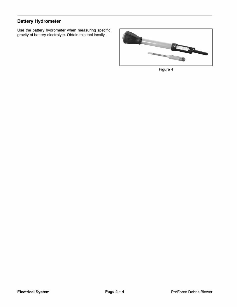
Battery Hydrometer
Use the battery hydrometer when measuring specificgravity of battery electrolyte. Obtain this tool locally.
Figure 4

ProForce Debris Blower Page 4 -- 5 Electrical System
Troubleshooting
CAUTION
Remove all jewelry, especially rings andwatches, before doing any electrical trouble-shooting or testing. Disconnect the batterycables unless the test requires battery voltage.
For effective troubleshooting and repairs, theremust bea good understanding of the electrical circuits (seeChapter 7 -- Electrical Diagrams) and components usedon this machine.
Starting Problems
Problem Possible Causes
Starter solenoid clicks, but starter will not crank. Battery is discharged.
Battery cables are loose or corroded.
Wire harness ground cable is loose or corroded.
Wiring at starter is faulty.
Starter solenoid is faulty.
Starter is faulty.
Nothing happens when start attempt is made. Battery is discharged.
Wiring to the start circuit components is loose,corroded or damaged (see Electrical Schematic inChapter 7 -- Electrical Diagrams).
Battery cables are loose or corroded.
Wire harness ground cable is loose or corroded.
Main fuse (15 amp) is loose or faulty.
Fusible link is faulty.
Ignition switch is faulty.
Starter solenoid is faulty.
Operator remote control or remote control module isfaulty.
Electrical
System

ProForce Debris BlowerPage 4 -- 6Electrical System
Starting Problems (Continued)
Problem Possible Causes
Engine cranks, but does not start. Ignition switch is faulty.
Magneto relay or circuit wiring is faulty.
Fuel relay or circuit wiring is faulty.
Diode is faulty.
Operator remote control or remote control module isfaulty.
Engine or fuel system is malfunctioning (see Chapter 3-- Engine).
Engine and fuel may be too cold.

ProForce Debris Blower Page 4 -- 7 Electrical System
General Run Problems
Problem Possible Causes
Battery does not charge. Wiring to charging circuit components is loose,corroded or damaged (see Electrical Schematic inChapter 7 -- Electrical Diagrams).
Voltage regulator is not properly grounded to engine.
Voltage regulator is faulty.
Ignition switch is faulty.
Battery is faulty.
Alternator stator or engine flywheel is faulty.
Engine stops during operation. Operator remote control button was inadvertentlypressed.
Ignition switch is faulty.
Fuse or fusible link is faulty.
Fuel, magneto and/or power relay is/are faulty.
Wiring to the run circuit components is broken ordisconnected (see Electrical Schematic in Chapter 7 --Electrical Diagrams).
Operator remote control or remote control module isfaulty.
Engine or fuel system is malfunctioning (see Chapter 3-- Engine).
Nozzle rotation motor does not operate. Wiring to the nozzle rotation motor is broken ordisconnected (see Electrical Schematic in Chapter 7 --Electrical Diagrams).
Nozzle rotation motor is faulty.
Operator remote control or remote control module isfaulty.
Electrical
System

ProForce Debris BlowerPage 4 -- 8Electrical System
Electrical System Quick Checks
Battery Test (Open Circuit Test)
Use a digital multimeter to measure the battery voltage.
Set the multimeter to the DC volts setting. The batteryshould be at a temperature of 60o to 100o F (16o to 38o
C). The ignition switch should be in theOFFposition andall accessories turnedoff.Connect thepositive (+)multi-meter lead to the positive battery post and the negative(--) multimeter lead to the negative battery post. Recordthe battery voltage.
NOTE: This test provides a relative condition of the bat-tery. Load testing of the battery will provide additionaland more accurate information (see Battery Service inthe Service and Repairs section).
Voltage Measured Battery Charge Level
12.68 volts Fully charged (100%)
12.45 volts 75% charged
12.24 volts 50% charged
12.06 volts 25% charged
11.89 volts 0% charged
Charging System Test
This is a simple test used to determine if a charging sys-tem is functioning. It will tell you if the charging systemhas an output, but not its capacity.
Use a digital multimeter set to DC volts. Connect thepositive (+) multimeter lead to the positive battery postand the negative (--) multimeter lead to the negative bat-tery post. Keep the test leads connected to the batteryposts and record the battery voltage.
NOTE: Upon starting the engine, the battery voltagewill drop and then should increase once the engine isrunning.
NOTE: Depending upon the condition of the batterycharge and battery temperature, the battery voltage willincrease at different rates as the battery charges.
Start the engine and run at high idle (3450 RPM). Allowthe battery to charge for at least 3 minutes. Record thebattery voltage.
After running the engine for at least 3 minutes, batteryvoltageshouldbeat least 0.50volt higher than initial bat-tery voltage.
An example of a charging system that is functioning:
At least 0.50 volt over initial battery voltage.
Initial Battery Voltage = 12.30 v
Battery Voltage after 3 Minute Charge = 12.85 v
Difference = +0.55 v

Rev. BProForce Debris Blower Page 4 -- 9 Electrical System
Component Testing
For accurate resistance and/or continuity checks, elec-trically disconnect the component being tested from thecircuit (e.g. unplug the switch connector before doing acontinuity check on switch).
CAUTION
When testing electrical components for continu-ity with a multimeter (ohms setting), make surethat power to the circuit has been disconnected.
Ignition Switch
The ignition (key) switch used on the ProForce DebrisBlower has three positions (OFF, RUN and START) .
On ProForce blowers with serial numbers below310000000, the ignition switch ismounted to the engineblower housing. This switch is shown in Figure 5 andswitch circuits are shown in Figure 6.
ProForce blowers with serial numbers above310000000 have the ignition switch mounted to theframe panel above the battery. This switch is shown inFigure 7 and switch circuits are shown in Figure 8.
Testing
1. Make sure that ignition switch is OFF.
2. To prevent unexpected machine operation, discon-nect the negative battery cable from the battery terminal(see Battery Service in the Service and Repairs sectionof this chapter). Position disconnected negative cableaway from the negative battery terminal.
3. On blowers with serial numbers below 310000000,removeengine blower housing to gain access to ignitionswitch (see theKohlerEngineServiceManual at theendof Chapter 3 -- Engine).
4. Unplug wire harness connectors from switch.
5. With the use of amultimeter (ohms setting), test igni-tion switch by verifying continuity between switch termi-nals for each switch position.
6. Connect the harness connectors to the switch aftertesting.
7. On blowers with serial numbers below 310000000,install blower housing onto engine (see the Kohler En-gine Service Manual at the end of Chapter 3 -- Engine).
8. Connect negative battery cable to negative batteryterminal. Tighten nut that secures battery cable from 10to 15 ft--lb (14 to 20N--m). Make sure that battery coveris secured.
Figure 5
45
45RUN
START
OFF
o
o
G
R B
S
M A
POSITION CIRCUITS
OFF G + M + A
RUN B + A + R
START B + S
Figure 6
Figure 7
REAR VIEWFRONT VIEW
A
B
C D
E
F
STARTOFF
RUN
45o 45o
POSITION CIRCUITS
OFF NONE
RUN B + C + F, D + E
START A + B + C
Figure 8
Electrical
System

ProForce Debris BlowerPage 4 -- 10Electrical System
Hour Meter
The hourmeter used on the ProForce Debris Blower re-cords the amount of time that the engine is running.
Testing
1. Make sure that ignition switch is OFF.
2. To prevent unexpected machine operation, discon-nect the negative battery cable from the battery terminal(see Battery Service in the Service and Repairs sectionof this chapter). Position disconnected negative cableaway from the negative battery terminal.
3. Locate wire harness connector at rear of hourmeter.Unplug harness connector from hour meter.
4. Connect the positive (+) terminal of a 12VDCsourceto the positive (+) terminal of the hour meter.
5. Connect the negative (--) terminal of the voltagesource to the other terminal of the hour meter.
6. The hour meter should move 1/10 of an hour in sixminutes.
7. Disconnect the voltage source from the hour meter.
8. Replace the hour meter if necessary.
9. Connect wire harness connector to hour meter.
10.Connect negative battery cable to negative batteryterminal. Tighten nut that secures battery cable from 10to 15 ft--lb (14 to 20N--m). Make sure that battery coveris secured.
Figure 7
QUARTZHobbs
HOURS10 0 0 0 1
10
+
BACKFRONT

ProForce Debris Blower Page 4 -- 11 Electrical System
Fuse
The ProForce Debris Blower uses a 15 amp fuse for cir-cuit protection. The fuse holder for this fuse is locatednext to the engine (Fig. 8).
The engine wire harness includes a 30 amp fuse for cir-cuit protection. Theengine fuse is located near the start-er motor (Fig. 9).
Testing
1. Make sure that ignition switch is OFF.
2. To prevent unexpected machine operation, discon-nect the negative battery cable from the battery terminal(see Battery Service in the Service and Repairs sectionof this chapter). Position disconnected negative cableaway from the negative battery terminal.
3. Press latch that retains fuse holder cover and raisecover to access fuse.
4. With theuseof amultimeter (ohmssetting), check forcontinuity between fuse terminals by using test ports attop of fuse. Fuse should have continuity between fuseterminals.
5. If necessary, remove and replace fuse.
6. Connect negative battery cable to negative batteryterminal. Tighten nut that secures battery cable from 10to 15 ft--lb (14 to 20N--m). Make sure that battery coveris secured.
1. Wire harness2. Fuse
3. Fuse cover
Figure 8
21
3
1. Engine fuse 2. Starter motor
Figure 9
1
2
Electrical
System

Rev. B ProForce Debris BlowerPage 4 -- 12Electrical System
Fusible Link (Serial Number Below 310000000)
ProForce Debris Blowers with a serial number below310000000 use a fusible link for circuit protection. Thisfusible link connects themainwire harness to the starterB+ terminal and positive battery cable (Fig. 12). If thelink should fail, current to the machine will cease. Referto electrical schematic and wire harness drawings inChapter 7 -- Electrical Diagrams for additional fusiblelink information.
Testing
1. Make sure that ignition switch is OFF.
2. To prevent unexpected machine operation, discon-nect the negative battery cable from the battery terminal(see Battery Service in the Service and Repairs sectionof this chapter). Position disconnected negative cableaway from the negative battery terminal.
3. Locate and unplug fusible link connector from ma-chine wire harness.
4. Use a multimeter to make sure that continuity existsbetween thedisconnected fusible link connector and thelink terminal at the starter motor (Fig. 13). If the fusiblelink is open (no continuity), replace the fusible link har-ness.
5. After testing is complete, make sure that fusible linkconnectors are securely attached to starter and ma-chine wire harness.
6. Connect negative battery cable to negative batteryterminal. Tighten nut that secures battery cable from 10to 15 ft--lb (14 to 20N--m). Make sure that battery coveris secured.
1. Fusible link 2. Starter B+ terminal
Figure 12
1
2
Figure 13
P1 J1BATTERY B+HARNESS
FUSIBLE LINK HARNESS

Rev. CProForce Debris Blower Page 4 -- 13 Electrical System
Relays
The electrical system on all ProForceDebris Blowers in-cludes a fuel relay that is used to energize the enginecarburetor fuel solenoid. When the ignition switch is inthe RUN or START position, the fuel relay is energizedby the Wireless Control Module.
ProForce blowers with serial numbers below310000000 include a second relay. The power relay onthese machines is used to provide machine electricalpower when it is energized by the Remote Control Mod-ule.
ProForce blower models 44538 and 44539 with serialnumbers above 312000000 include an additional three(3) relays: a start relay and two (2) relays for energizingthe chute rotation motor. These relays are energized bythe Wireless Control Module when a remote transmitterinput is entered for engine starting or chute rotation.
The relays are secured to the control tower bracket nextto the engine. The relays can be identified by the wirecolors at the wire harness connector (seeWire HarnessDrawings in Chapter 7 -- Electrical Diagrams).
Testing
1. Make sure that ignition switch is OFF.
2. To prevent unexpected machine operation, discon-nect the negative battery cable from the battery terminal(see Battery Service in the Service and Repairs sectionof this chapter). Position disconnected negative cableaway from the negative battery terminal.
3. Locate relay and disconnect the machine wire har-ness connector from the relay. Remove relay from ma-chine for easier testing.
NOTE: Prior to taking small resistance readings with adigital multimeter, short the meter test leads together.The meter will display a small resistance value (usually0.5 ohms or less). This resistance is due to the internalresistance of the meter and test leads. Subtract this val-ue from the measured value of the component you aretesting.
4. Using a multimeter (ohms setting), measure coil re-sistance between terminals 85 and 86 (Fig. 14). Resist-ance should be between 70 and 90 ohms.
5. Connectmultimeter (ohms setting) leads to relay ter-minals 30 and 87. Ground terminal 86 and apply +12VDC to terminal 85. The relay should have continuity be-tween terminals 30 and 87 as +12 VDC is applied to ter-minal 85. The relay should not have continuity betweenterminals 30 and 87 as +12 VDC is removed from termi-nal 85.
6. Disconnect voltage and multimeter leads from therelay terminals.
7. Connectmultimeter (ohms setting) leads to relay ter-minals 30 and 87A. Ground terminal 86 and apply +12VDC to terminal 85. The relay should not have continuitybetween terminals 30 and 87A as +12 VDC is applied toterminal 85. The relay should have continuity betweenterminals 30 and 87A as +12 VDC is removed from ter-minal 85.
8. Disconnect voltage and multimeter leads from therelay terminals.
9. Secure relay to machine and connect machine wireharness connector to relay.
10.Connect negative battery cable to negative batteryterminal. Tighten nut that secures battery cable from 10to 15 ft--lb (14 to 20N--m). Make sure that battery coveris secured.
Figure 14
86
85
87A 87
30
Electrical
System

Rev. C ProForce Debris BlowerPage 4 -- 14Electrical System
Remote Transmitter (Machines with Single Channel Controller)
NOTE: Machines with a single channel controller canbe identified by the external antenna on the controlmod-ule (Fig. 15).
The remote transmitter is a solid state electrical devicethat sends radio frequency (RF) signal inputs to the ma-chine control module for control of machine electricaloperation (Fig. 15). The remote transmitter has suffi-cient range to send an RF signal to the control modulefrom the tow vehicle operator position.
When a button on the remote transmitter is pressed, theLED on the remote should flicker (Fig. 16). If the ma-chine control module is energized (control module TimeOut andPower LED’s are both illuminated) and a remotetransmitter button is pressed, the corresponding controlmodule LED should illuminate and the control moduleRF activity LED should flicker.
If the control module is energized (control module TimeOut and Power LED’s are both illuminated), remote but-ton functions are as follows:
Pressing the Engine Start button initiates a starting se-quence to start the engine. This sequence (see Opera-tor’s Manual) is necessary to prevent accidental enginestarting. After pressing the Engine Start button, the RHNozzle and LH Nozzle Rotate buttons are inactive forfive (5) seconds.
Pressing the Speed Increase (rabbit) button when theengine is running causes the engine speed to increase.
Pressing the Speed Decrease (turtle) button when theengine is running causes the engine speed to decrease.
Pressing the RHNozzle Rotate button causes the blow-er nozzle to rotate to the right.
Pressing the LH Nozzle Rotate button causes the blow-er nozzle to rotate to the left.
Pressing the engine Stop button causes the engine tostop running.
NOTE: When the engine stop button on the remotetransmitter is pressed, there will be a one (1) seconddelay before the engine stop LED on the control moduleilluminates. Also, for approximately five (5) seconds af-ter the stop button is pressed, the controlmodule enginestop LED will remain illuminated and no other remotetransmitter operations can be performed.
The remote transmitter is powered by three (3) AAA al-kaline batteries. If the range of the transmitter has dimin-ished or the transmitter LED does not flicker when abutton is pressed, the batteries should be replaced.
Remote Transmitter Battery Replacement
1. Remove six (6) screws that secure the rear cover tothe remote transmitter.
2. Lift rear cover from remote transmitter.
3. Remove batteries from remote transmitter and re-place with three (3) new AAA alkaline batteries.
4. Place rear cover on remote transmitter and securewith six (6) screws.
1. Remote transmitter2. Control module
3. External antennaFigure 15
21
3
1. Speed increase2. Speed decrease3. RH nozzle rotate4. LH nozzle rotate
5. Engine stop6. Engine start7. Remote control LED
Figure 16
1
3
5
4
2
7
6

Rev. CProForce Debris Blower Page 4 -- 15 Electrical System
Remote Transmitter (Machines with Multi Channel Controller)
NOTE: Machines with a multi channel controller can beidentified by the lack of an external antenna on the con-trol module (Fig. 17).
NOTE: Additional information regarding the remotetransmitter is included in the Operator’s Manual.
The remote transmitter is a solid state electrical devicethat sends radio frequency (RF) signal inputs to the ma-chine control module for control of machine electricaloperation (Fig. 17). The remote transmitter has suffi-cient range to send an RF signal to the control modulefrom the tow vehicle operator position.
When a button on the remote transmitter is pressed, theTX LED on the remote should illuminate and then blink(Fig. 18). If the machine control module is energized(control module health LED is illuminated) and a remotetransmitter button is pressed, the control module TX/RXLED should blink.
If the controlmodule is energized (controlmodule healthLED is illuminated), remote transmitter button functionsare as follows:
Pressing the Engine Start button initiates a starting se-quence to start the engine. This sequence (see Opera-tor’s Manual) is necessary to prevent accidental enginestarting. If any transmitter buttons are pressed out of or-der during the starting sequence, the sequence will beaborted.
Pressing the LH Nozzle Rotate button causes the blow-er nozzle to rotate to the left.
Pressing the RHNozzle Rotate button causes the blow-er nozzle to rotate to the right.
Pressing the Speed Decrease (turtle) button when theengine is running causes the engine speed to decrease.
Pressing the Speed Increase (rabbit) button when theengine is running causes the engine speed to increase.
NOTE: Pressing the speed increase and speed de-crease buttons simultaneously will return the engine tolow idle speed.
Pressing the Engine Stop button causes the engine tostop running.
The remote transmitter is powered by three (3) AAA al-kaline batteries. If the range of the transmitter has dimin-ished or the transmitter TX LED does not illuminatewhen a button is pressed, the transmitter batteriesshould be replaced.
1. Remote transmitter 2. Control module
Figure 17
2
1
Figure 18
1 2
3 4
5 69
7
8
1. LH nozzle rotate2. RH nozzle rotate3. Speed decrease4. Speed increase5. Engine start
6. Engine stop7. TX LED8. RX LED9. Link LED
Electrical
System

Rev. C ProForce Debris BlowerPage 4 -- 16Electrical System
Wireless Control Module (Machines with Single Channel Controller)
NOTE: Machines with a single channel controller canbe identified by the external antenna on the controlmod-ule (Fig. 15).
Thewireless controlmodule is a solid state electrical de-vice that receives signal inputs from the remote trans-mitter and uses those inputs to control machineelectrical operation. The control module is attached tothe frame next to the battery (Fig. 19).
Inputs from the ignition switch and the remote transmit-ter are monitored by the control module. Output to themagneto relay, fuel relay, power relay, engine startermotor solenoid, engine throttle control module andnozzle rotationmotor are controlled based on the inputsreceived by the control module.
To start blower operation, rotation of the ignition switchto the START position is used to turn on or “wake up” thecontrol module. The control module Time Out and Pow-er LED’s should both be illuminated during blower op-eration (Fig. 20).
When a remote transmitter button is pressed, the corre-sponding control module LED should illuminate and thecontrol module RF activity LED should flicker (Fig. 20).
NOTE: Because of the normal RF activity in the envi-ronment, the control module RF activity LEDmay flickeror be illuminated at any time during machine operation.Machine operation will only be controlled by the remotetransmitter that is recognized by the control module.
NOTE: When the engine stop button on the remotetransmitter is pressed, there will be a one (1) seconddelay before the control module engine stop LED illumi-nates. Also, the control module engine stop LED will re-main illuminated and no other remote transmitteroperations can be performed for about five (5) seconds.
The control module includes a time--out feature to allowmachine operation for a time period after the last controlinput (e.g. key switch turned off or remote transmitterbutton pressed). If no inputs are provided to the controlmodule during this time period, the control module willshut off all machine electrical power including turning offthe engine, if running.When the engine is turned off witheither the key switch or the remote transmitter, the con-trol module Time Out and Power LED’s will both be illu-minated for this time period. Refer to your Operator’sManual for additional details on the time--out feature.
The control module does not connect to an externalcomputer or hand held device, can not be re--pro-grammed and does not record any fault data. The ma-chine wire harness does include a communication portwith loopback connector that should remain connected.
Because of the solid state circuitry built into the controlmodule, there is no reliablemethod to test it. Themodulemay be damaged if an attempt is made to test it with anelectrical test device, such as a digital multimeter.
IMPORTANT: Before performing anywelding on themachine, disconnect the negative battery cablefrom the battery and the wire harness connectorfrom the wireless control module to prevent dam-age to the electrical system.
Figure 19
2
1
1. Remote transmitter2. Control module
3. External antenna
3
1. Speed increase LED2. Speed decrease LED3. RH nozzle rotate LED4. LH nozzle rotate LED5. Engine stop LED
6. Engine start LED7. Time out LED8. Power LED9. RF activity LED
Figure 20
Tested to Compl yWith FCC Standar ds
FOR HOME OR OFFICE USE
Canada3575APFB1
Model: 44538
N 1 6 2 5
Made in U.S .A.
2
1
4
3
6
5 8
7
9

Rev. CProForce Debris Blower Page 4 -- 17 Electrical System
Wireless Control Module (Machines with Multi Channel Controller)
NOTE: Machines with a multi channel controller can beidentified by the lack of an external antenna on the con-trol module (Fig. 21).
Thewireless controlmodule is a solid state electrical de-vice that receives signal inputs from the remote trans-mitter and uses those inputs to control machineelectrical operation. The control module is attached tothe frame next to the engine.
Inputs from the machine ignition switch and the remotetransmitter are monitored by the control module. Outputto the fuel relay, start relay, engine starter motor sole-noid, engine throttle control module and nozzle rotationrelays are controlled basedon the inputs received by thecontrol module.
To start blower operation, rotation of the ignition switchto the START position is used to turn on or “wake up” thecontrol module. The control module Health LED shouldbe illuminated green during normal blower operation(Fig. 22). If the Health LED is illuminated either yellowor red, a problem exists with the controller.
Whena remote transmitter button is pressed, the controlmodule TX/RX LED should flicker (Fig. 22). The TX/RXLED will be green when the module is receiving a signalfrom the remote and will be red when the module istransmitting.
NOTE: Because of the normal RF activity in the envi-ronment, the control module TX/RX LED may flicker orbe illuminated at any time during machine operation.Machine operation will only be controlled by the remotetransmitter that is associated to the control module.
The control module includes a power save mode if themodule is active for more than 2.5 hours without com-munication from the remote transmitter. Once in thepower save mode, the control module will not commu-nicate with the remote transmitter, will not activate anymachine outputs and will not function normally. All ma-chine electrical power will be shut--off including turningoff the engine, if running. Refer to your Operator’sManual for additional details on the power save mode.
The control module does not connect to an externalcomputer or hand held device, can not be re--pro-grammed and does not record any fault data. Becauseof the solid state circuitry built into the control module,there is no reliable method to test it. Themodule may bedamaged if an attempt ismade to test it with an electricaltest device, such as a digital multimeter.
IMPORTANT: Before performing anywelding on themachine, disconnect the negative battery cablefrom the battery and the wire harness connectorfrom the wireless control module to prevent dam-age to the electrical system.
1. Remote transmitter 2. Control module
Figure 21
2
1
1. Health LED 2. TX/RX LED
Figure 22
1
2
Electrical
System

Rev. B ProForce Debris BlowerPage 4 -- 18Electrical System
Diode Assembly (Serial Number Below 310000000)
ProForce Debris Blowers with a serial number below310000000 use a diode assembly in the wire harness(Fig. 23) (see wire harness drawings in Chapter 7 --Electrical Diagrams). The diode allows the initial currentflow to energize or “wake up” the remote controlmodule.
Testing
1. Make sure that ignition switch is OFF.
2. To prevent unexpected machine operation, discon-nect the negative battery cable from the battery terminal(see Battery Service in the Service and Repairs sectionof this chapter). Position disconnected negative cableaway from the negative battery terminal.
3. Locate diode assembly and remove cable tie that se-cures diode to machine wire harness.
4. Unplug the diode from the wire harness for testing.
5. The diode (Fig. 24) can be tested using a digitalmultimeter (diode test or ohms setting) and the table inthe right column.
6. After testing is complete,make sure that diode is fullyinstalled into machine wire harness connector and se-cured to harness with cable tie.
7. Connect negative battery cable to negative batteryterminal. Tighten nut that secures battery cable from 10to 15 ft--lb (14 to 20N--m). Make sure that battery coveris secured.
1. Machine wire harness 2. Diode assembly
Figure 23
21
Figure 241. Diode2. Male terminal
3. Female terminal
12
3
MultimeterRed Lead (+)on Terminal
MultimeterBlack Lead (--)on Terminal
Continuity
Female Male YES
Male Female NO

ProForce Debris Blower Page 4 -- 19 Electrical System
This page is intentionally blank.
Electrical
System

ProForce Debris BlowerPage 4 -- 20Electrical System
Service and Repairs
NOTE: See the Kohler Engine Service Manual (in-cluded at the end of Chapter 3 -- Engine) for engine elec-trical component repair information.
Nozzle Motor
1. Nozzle2. Nozzle clamp3. V belt4. Housing assembly5. Flat washer (10 used)6. R--clamp7. Nozzle motor8. Motor bracket9. Cap screw (3 used)
10. Drive pulley11. Lock nut12. Cap screw (2 used)13. Belt guard14. Flange head screw (2 used)15. Flat washer16. Cap screw17. Flange nut (2 used)18. Flange nut
19. Leaf spring20. Bearing21. Cap screw (2 used)22. Flange nut (2 used)23. Shoulder bolt24. Lock nut25. Nozzle pulley26. Nozzle guide
Figure 25
FRONT
RIGHT
1
3
2
6
4
15
16
18
20
7
8
9
1011
12
1314
17
19
20
21
22
2315
5
24
1620
25
26
NOTE: If nozzle motor wear or damage occurs, motorreplacement is necessary. Individual components forthe nozzle motor are not available.

ProForce Debris Blower Page 4 -- 21 Electrical System
Removal (Fig. 25)
1. Position machine on a firm, level surface. Make sureengine is stopped and remove key from the ignitionswitch. Chock wheels to prevent machine from moving.
2. To prevent unexpected machine operation, discon-nect the negative battery cable from the battery terminal(see Battery Service in the Service and Repairs sectionof this chapter). Position disconnected negative cableaway from the negative battery terminal.
3. Unplug wire harness connector from nozzle motor.
4. Loosen, but do not fully remove, flange nut that se-cures drive pulley to nozzle motor shaft. Loosen flangenut at least two turns.
5. Remove two (2) cap screws (item21) and flangenuts(item 22) that secure leaf spring to motor bracket. Re-move leaf spring with bearing and flat washers (item 5)from bracket.
6. Loosen two (2) flange head screws (item 14) andflange nuts that secure nozzle motor bracket to outerhousing. Rotate bracket and nozzle motor to loosen v--belt.
7. Loosen cap screws and flange nuts that secure beltguard (item 13), route v--belt from behind guard andcarefully remove belt from machine.
NOTE: The shaft of the nozzle motor is tapered.
8. Use appropriate puller to loosen drive pulley fromnozzle motor.
9. Remove flange nut and drive pulley from nozzle mo-tor shaft.
10.Support nozzle motor to prevent it from falling. Re-move three (3) cap screws that secure nozzle motor tobracket. Remove nozzle motor from machine.
Installation (Fig. 25)
1. Position nozzle motor to bracket and secure withthree (3) cap screws.
2. Thoroughly clean tapered surfaces of motor shaftand drive pulley.
3. Slide drive pulley onto motor shaft and secure withflange nut.
4. Place v--belt in nozzle pulley, route behind belt guard(item 13) and install belt on motor pulley.
5. With a 3/8 in. drive torque wrench, pivot the motorbracket from 200 to 230 in--lb (23 to 25 N--m) to set v--belt tension (Fig. 26). Do not over tension belt. Holdbracket with the torque wrench and tighten two (2)flange head screws and flange nuts to secure belt ad-justment and nozzle motor bracket.
6. Center belt guard around v--belt. Tighten cap screwsand flange nuts to secure belt guard to machine.
7. Position leaf spring with bearing and flat washers(item 5) to bracket. Make sure that five (5) washers areplaced between spring and bracket at each mountinghole. The bearing on the leaf spring should be centeredon the outside of the v--belt. Secure leaf spring to motorbracket with two (2) cap screws (item 21) and flangenuts (item 22).
8. Connect wire harness to nozzle motor.
9. Connect negative battery cable to negative batteryterminal. Tighten nut that secures battery cable from 10to 15 ft--lb (14 to 20N--m). Make sure that battery coveris secured.
1. Drive pulley2. Leaf spring
3. Flange head screw4. Torque wrench access
Figure 26
1
2
3
3
4
Electrical
System

ProForce Debris BlowerPage 4 -- 22Electrical System
Battery Storage
If the machine will be stored for more than 30 days:
1. Remove the battery from the machine and charge itfully (see Battery Service).
2. Either store battery on a shelf or on the machine.
3. Leave battery cables disconnected if the battery isstored on the machine.
4. Store battery in a cool atmosphere to avoid quick de-terioration of the battery charge.
5. To help prevent the battery from freezing, make sureit is fully charged (see Battery Service).
Battery Care
1. Battery electrolyte level must be properly main-tained. The top of the battery must be kept clean. lf themachine is stored in a location where temperatures areextremely high, the battery will discharge more rapidlythan if the machine is stored in a location where temper-atures are cool.
Wear safety goggles and rubber gloves whenworkingwith electrolyte. Chargebattery in awellventilated place so gasses produced whilecharging can dissipate. Since the gases are ex-plosive, keep open flames and electrical sparksaway from the battery; do not smoke. Nauseamay result if the gases are inhaled. Unplug char-ger from electrical outlet before connecting ordisconnecting charger leads to or from batteryposts.
CAUTION
IMPORTANT: Do not remove battery fill caps whilecleaning.
2. Check battery condition weekly or after every 50hours of operation. Keep terminals and entire batterycase clean because a dirty battery will discharge slowly.
A. Clean battery by washing entire case with a solu-tion of baking soda andwater. Rinsewith clear water.
B. Coat battery posts and cable connectors withBattery Terminal Protector (Toro Part No. 107--0392)or petroleum jelly to prevent corrosion.
3. Battery cables must be tight on terminals to providegood electrical contact. Tighten nuts that secure batterycables from 10 to 15 ft--lb (14 to 20 N--m).
Connecting battery cables to the wrong bat-tery post could result in personal injury and/ordamage to the electrical system.
CAUTION
4. If corrosion occurs at battery terminals, disconnectcables. Always disconnect negative (--) cable first.Clean clamps and terminals separately. Reconnectcables to battery with positive (+) cable first. Coat bat-tery posts and cable connectors with Battery TerminalProtector (Toro Part No. 107--0392) or petroleum jelly toprevent corrosion.
5. Periodically (at least every 50 operating hours)check battery electrolyte level. Check electrolyte levelevery 30 days if machine is in storage.
6. Maintain battery cell level with distilled water. Do notfill battery cells above the fill line.

ProForce Debris Blower Page 4 -- 23 Electrical System
Battery Service
The battery is the heart of the electrical system. Withregular and proper service, battery life can be extended.Additionally, battery and electrical component failurecan be prevented.
CAUTION
When working with batteries, use extreme cau-tion to avoid splashing or spilling electrolyte.Electrolyte can destroy clothing and burn skinand eyes. Alwayswear safety goggles and a faceshield when working with batteries.
Electrolyte Specific GravityFully charged: 1.265 corrected to 80oF (26.7oC)Discharged: less than 1.240
Battery SpecificationsBCI Group Size 28535 CCA at 0o F (--18o C)Reserve Capacity of 110 minutes at 80oF (27oC)
Dimensions (including terminal posts)Length 10.3 inches (26.2 cm)Width 6.8 inches (17.3 cm)Height 9.5 inches (24.1 cm)
Battery Removal and Installation (Fig. 27)
1. Make sure that ignition switch is in the OFF positionand that none of the LED’s on Remote Control Moduleare illuminated. Loosen strap and remove battery boxcover.
2. Loosen and remove negative cable from battery. Af-ter negative cable has been removed, loosen and re-move positive cable.
3. Carefully remove battery from machine.
4. Install battery in reverse order making sure to con-nect and tighten positive cable to battery before con-necting negative cable. Tighten nuts that secure batterycables from 10 to 15 ft--lb (14 to 20 N--m).
NOTE: Before connecting the negative (ground) cableto the battery, connect a digital multimeter (set to DCAmps) between the negative battery post and the nega-tive (ground) cable connector. The reading should beless than 0.1 amp. If the reading is 0.1 amp or more, themachine’s electrical system should be tested for shortcircuits or faulty components and repaired.
5. Install battery box cover and secure with strap.
1. Strap2. Battery box cover3. Battery4. Battery box
5. Positive cable6. Negative cable7. Flange nut
Figure 27
1
3
2
4
5
6
7FRONT
RIGHT
Battery Inspection and Maintenance
1. Check battery case for cracks. Replace battery ifcracked or leaking.
2. Check battery terminals for corrosion. If corrosionoccurs at terminals, disconnect cables. Always discon-nect negative (--) cable first. Clean cable clamps andbattery terminals separately. Reconnect cables withpositive (+) cable first. Coat battery posts and cable con-nectors with Battery Terminal Protector (Toro Part No.107--0392) or petroleum jelly to prevent corrosion.
IMPORTANT: Before cleaning the battery, tape orblock vent holes to the filler caps andmake sure thecaps are on tightly.
3. Check for signs of wetness or leakage on the top ofthe battery which might indicate a loose or missing fillercap, overcharging, loose terminal post or overfilling.Also, check battery case for dirt and oil. Clean the bat-tery with a solution of baking soda and water, then rinseit with clean water.
4. Check that the cover seal is not broken away. Re-place the battery if the seal is broken or leaking.
5. Check the electrolyte level in each cell. If the level isbelow the tops of the plates in any cell, fill all cells withdistilled water between the minimum and maximum filllines. Charge at 15 to 25 amps for 15 minutes to allowsufficient mixing of the electrolyte.
Electrical
System

ProForce Debris BlowerPage 4 -- 24Electrical System
Battery Testing
1. Conduct a hydrometer test of the battery electrolyte.
IMPORTANT: Make sure the area around the cells isclean before opening the battery caps.
A. Measure the specific gravity of each cell with ahydrometer. Draw electrolyte in and out of thehydrometer barrel prior to taking a reading to warm--up the hydrometer. At the same time take the tem-perature of the cell.
B. Temperature correct each cell reading. For each10oF (5.5oC) above 80oF (26.7oC) add 0.004 to thespecific gravity reading. For each 10oF (5.5oC) be-low 80oF (26.7oC) subtract 0.004 from the specificgravity reading.
Example: Cell Temperature 100oFCell Gravity 1.245100oF minus 80oF equals 20oF(37.7oC minus 26.7oC equals 11.0oC)20oF multiply by 0.004/10oF equals 0.008(11oC multiply by 0.004/5.5oC equals 0.008)ADD (conversion above) 0.008Correction to 80oF (26.7oC) 1.253
C. If the difference between the highest and lowestcell specific gravity is 0.050 or greater or the lowestcell specific gravity is less than1.225, charge thebat-tery. Charge at the recommended rate and time giv-en in Charging or until specific gravity of all cells is1.225 or greater with the difference in specific gravitybetween the highest and lowest cell less than 0.050.If these charging conditions can not be met, replacethe battery.
2. Perform a high--discharge test with an adjustableload tester.
This is oneof themost reliablemeansof testing abatteryas it simulates the cold--cranking test. A commercial bat-tery load tester is required to perform this test.
CAUTION
Follow the battery load tester manufacturer’sinstructions when using a battery load tester.
A. Check the voltage across the battery terminalsprior to load testing the battery. If the voltage is lessthan 12.4 VDC, recharge the battery.
B. If the battery has recently been charged, removethe battery surface charge before performing theload test. Disconnect the engine fuel stop solenoid toprevent the engine from starting. Engage the startermotor for 10 seconds to remove battery surfacecharge. Reconnect the fuel stop solenoid.
C. Make sure battery terminals are free of corrosion.
D. Measure the temperature of the center batterycell.
E. Connect a battery load tester to the battery termi-nals following the load tester manufacturer’s in-structions. Connect a digital multimeter to thebattery terminals.
F. Apply a test load of 270 amps (one half theCrank-ing Performance rating of the battery) for 15 se-conds.
G. Take a voltage reading after 15 seconds, then re-move the load.
H. Using the table below, determine the minimumvoltage for the cell temperature reading:
MinimumVoltage
Battery ElectrolyteTemperature
9.6 70oF (and up) 21.1oC (and up)
9.5 60oF 15.6oC
9.4 50oF 10.0oC
9.3 40oF 4.4oC
9.1 30oF --1.1oC
8.9 20oF --6.7oC
8.7 10oF --12.2oC
8.5 0oF --17.8oC
I. If the test voltage is below the minimum, replacethe battery. If the test voltage is at or above the mini-mum, return the battery to service.

ProForce Debris Blower Page 4 -- 25 Electrical System
Battery Charging
To minimize possible damage to the battery and allowthe battery to be fully charged, the slow charging meth-od is presented here. This charging method can be ac-complished with a constant current battery chargerwhich is commonly available.
CAUTION
Follow the battery charger manufacturer’sinstructions when using a battery charger.
NOTE: Using specific gravity of the battery cells is themost accurate method of determining battery condition.
1. Determine the battery charge level from either itsspecific gravity or open circuit voltage.
Battery ChargeLevel
SpecificGravity
Open CircuitVoltage
100% 1.265 12.68
75% 1.225 12.45
50% 1.190 12.24
25% 1.155 12.06
0% 1.120 11.89
2. Determine the charging time and rateusing the bat-tery charger manufacturer’s instructions or the fol-lowing table:
BatteryReserveCapacity(Minutes)
Battery Charge Level(Percent of Fully Charged)
75% 50% 25% 0%
80 or less 3.8 hrs@
3 amps
7.5 hrs@
3 amps
11.3 hrs@
3 amps
15 hrs@
3 amps
81 to 125 5.3 hrs@
4 amps
10.5 hrs@
4 amps
15.8 hrs@
4 amps
21 hrs@
4 amps
126 to170
5.5 hrs@
5 amps
11 hrs@
5 amps
16.5 hrs@
5 amps
22 hrs@
5 amps
171 to250
5.8 hrs@
6 amps
11.5 hrs@
6 amps
17.3 hrs@
6 amps
23 hrs@
6 amps
above250
6 hrs@
10 amps
12 hrs@
10 amps
18 hrs@
10 amps
24 hrs@
10 amps
CAUTION
Donot charge a frozen battery because it can ex-plode and cause injury. Let the battery warm to60o F (15.5o C) before connecting to a charger.
Charge the battery in a well--ventilated place todissipate gases produced from charging. Thesegases are explosive; keep open flame and elec-trical spark away from the battery. Do not smoke.Nausea may result if the gases are inhaled. Un-plug the charger from the electrical outlet beforeconnecting or disconnecting the charger leadsfrom the battery posts.
3. Following the battery charger manufacturer’sinstructions, connect the charger cables to the battery.Make sure a good connection is made.
4. Charge the battery following the battery chargermanufacturer’s instructions.
5. Occasionally check the temperature of the batteryelectrolyte. If the temperature exceeds 125oF (51.6oC)or the electrolyte is violently gassing or spewing, thecharging rate must be lowered or temporarily stopped.
6. Three hours prior to the end of the charging, mea-sure the specific gravity of a battery cell once per hour.The battery is fully charged when the cells are gassingfreely at a low charging rate and there is less than a0.003 change in specific gravity for three consecutivereadings.
Electrical
System

ProForce Debris BlowerPage 4 -- 26Electrical System
This page is intentionally blank.

Rev. CProForce Debris Blower Page 5 -- 1 Blower Assembly
Chapter 5
Blower Assembly
Table of Contents
GENERAL INFORMATION 2. . . . . . . . . . . . . . . . . . . . .Operators Manual 2. . . . . . . . . . . . . . . . . . . . . . . . . . .Electrical Power 2. . . . . . . . . . . . . . . . . . . . . . . . . . . .
SPECIAL TOOLS 3. . . . . . . . . . . . . . . . . . . . . . . . . . . . .SERVICE AND REPAIRS 4. . . . . . . . . . . . . . . . . . . . . .Blower Drive Shaft 4. . . . . . . . . . . . . . . . . . . . . . . . . .Rotor Assembly 6. . . . . . . . . . . . . . . . . . . . . . . . . . . . .Rotor Shaft (Serial Number Below 313000000) 8.Rotor Shaft (Serial Number Above 313000000) 10Nozzle Assembly 12. . . . . . . . . . . . . . . . . . . . . . . . . .Inner Housing Assembly 14. . . . . . . . . . . . . . . . . . . .
Blower
Assem
bly

ProForce Debris BlowerPage 5 -- 2Blower Assembly
General Information
Operator’s Manual
The Operator’s Manual provides information regardingthe operation, general maintenance and maintenanceintervals for your ProForce Debris Blower machine. Re-fer to the Operator’s Manual for additional informationwhen servicing the machine.
Electrical Power
Electrical power to ProForce Debris Blower compo-nents is controlled by the Remote Control Module. Tomake sure thatmachine operation does not occur unex-pectedly, disconnect the negative battery cable from thebattery before performing any machine service (seeBattery Service in the Service and Repairs section ofChapter 4 -- Electrical System).
Reattach the disconnected negative battery cable asthe last step in any repair. Secure cable with flange nut.Torque nut from 10 to 15 ft--lb (14 to 20 N--m).

ProForce Debris Blower Page 5 -- 3 Blower Assembly
Special Tools
Offset Wrench
The offset wrench is used to properly tighten the nutsthat secure the rotor assembly to the rotor shaft. Usewith 1/2” torque wrench at right angle to offset wrenchhandle to ensure that proper torque is applied to nut.
NOTE: Two (2) offset wrenches are required to proper-ly tighten the rotor assembly nuts.
Toro Part Number: TOR6006
Figure 1
Blower
Assem
bly

ProForce Debris BlowerPage 5 -- 4Blower Assembly
Service and Repairs
Blower Drive Shaft
1. Flange nut2. Fan hub3. Cap screw4. Spacer5. Spacer
6. Flat washer7. Cap screw8. Drive coupling9. Flat washer
10. Cap screw11. Woodruff key12. Drive shaft13. Engine hub and coupling assembly
Figure 2
FRONT
RIGHT
67
3
2
5
4
89
10
12
13
3
5
9
10
11
1
1
41
9
1
11Loctite #242
300 to 330 in--lb(34 to 37 N--m)
300 to 330 in--lb(34 to 37 N--m)
NOTE: The coupling assembly between the blowershaft and drive shaft (item 12) is illustrated in Figure 2.The coupling assembly (item 13) used between thedrive shaft (item12) andengineshaft is composedof thesame components (Fig. 3).

Rev. BProForce Debris Blower Page 5 -- 5 Blower Assembly
Removal (Fig. 2)
1. Positionmachine on a firm, level surface. Make sureengine is stopped and remove key from the ignitionswitch. Chock wheels to prevent machine frommoving.
2. To prevent unexpected machine operation, discon-nect the negative battery cable from the battery terminal(see Battery Service in the Service and Repairs sectionof Chapter 4 -- Electrical System). Position discon-nected negative cable away from the negative batteryterminal.
3. Remove top grill to allowaccess to blower drive shaft(see Guards Removal in the Service and Repairs sec-tion of Chapter 6 -- Chassis).
4. Remove cap screws, flat washers and lock nuts thatsecuredrive shaft assembly to hubsonengine shaft andblower shaft.
5. Lift drive shaft assembly from machine.
6. Disassemble drive couplings from drive shaft usingFigures 2 and 3 as guides. Note differences in couplingspacer flange thickness for assembly purposes.
7. Inspect drive couplings for damage and replace ifnecessary.
8. If necessary, remove hubs from engine shaft andblower shaft:
A. Remove cap screw and flat washer that securehub to shaft.
NOTE: Hubhasa tapered IDandwill requireapullerto remove it from shaft.
B. Use appropriate puller to remove hub from shaft.
C. Remove woodruff key from shaft slot.
Installation (Fig. 2)
1. If hub was removed from engine shaft or blowershaft, thoroughly clean tapers of shaft(s) and hub(s). Fitwoodruff key to shaft slot and place hub on shaft. ApplyLoctite #242 (or equivalent) to threads of cap screwused to secure hub to shaft. Securehub to shaftwith capscrew and flat washer.
2. Place coupling spacers into rubber coupling.
3. Securedrive couplings to drive shaftwith cap screwsand lock nuts using Figures 2 and 3 as guides.
4. Position drive shaft assembly to engine shaft andblower shaft.
5. Secure drive shaft assembly to hubs on engine shaftand blower shaft with cap screws, flat washers and locknuts.
6. Install top grill to machine (seeGuards Installation inthe Service and Repairs section of Chapter 6 -- Chas-sis).
7. Connect negative battery cable to negative batteryterminal. Tighten nut that secures battery cable from 10to 15 ft--lb (14 to 20N--m). Make sure that battery coveris secured.
1. Cap screw2. Flat washer3. Cap screw4. Spacer5. Cap screw6. Woodruff key
7. Shaft hub8. Flat washer9. Flange nut10. Spacer11. Drive coupling12. Fan hub/coupling
Figure 3
12
3
456
78
9
10
11
12
300 to 330 in--lb(34 to 37 N--m)Loctite #242
Blower
Assem
bly

Rev. B ProForce Debris BlowerPage 5 -- 6Blower Assembly
Rotor Assembly
1. Inlet bell2. Retaining ring3. Wave washer (up to 3 used)4. Front cap5. Nut (LH threads)
6. Spacer7. Rotor assembly8. Woodruff key9. Rotor shaft
10. Outer housing11. Flange nut (8 used)12. Washer (as needed)13. Cap screw (8 used)
Figure 4
FRONT
RIGHT
1
6
7
32
5
4
8
910
11
Loctite #242
12
13
See text fortightening procedure
SERIAL NUMBER BELOW 310000000
NOTE: ProForce blowers with a serial number below310000000 use two (2) nuts to secure rotor assembly torotor shaft (Fig. 4). Blowers with serial numbers above310000000 use one (1) nut (Fig. 5).
Removal (Fig. 4)
1. Positionmachine on a firm, level surface. Make sureengine is stopped and remove key from the ignitionswitch. Chock wheels to prevent machine frommoving.
2. To prevent unexpected machine operation, discon-nect the negative battery cable from the battery terminal(see Battery Service in the Service and Repairs sectionof Chapter 4 -- Electrical System). Position discon-nected negative cable away from the negative batteryterminal.
3. Remove top grill to allow access to blower assembly(see Guards Removal in the Service and Repairs sec-tion of Chapter 6 -- Chassis).
4. Remove blower drive shaft frommachine (seeBlow-er Drive Shaft Removal in this section).
5. Remove retaining ring (item 2), wave washer(s)(item 3) and front cap (item 4) from shaft.
NOTE: When loosening nuts that secure rotor assem-bly to rotor shaft, use a 1 1/4” wrench in flats on shaft toprevent the shaft from turning.
IMPORTANT: The nuts used to secure the rotor as-sembly to the rotor shaft have left hand threads.Loosen these nuts by rotating clockwise.

Rev. BProForce Debris Blower Page 5 -- 7 Blower Assembly
6. Remove nut(s) that secures rotor assembly:
A. On machines with serial numbers below310000000 (Fig. 4), remove outer nut from rotorshaft by rotating nut in a clockwise direction. Then,remove inner nut by rotating nut clockwise. Use off-set wrench (see Special Tools) to loosen nuts fromrotor shaft.
B. On machines with serial numbers above310000000 (Fig. 5), straighten inner tab washer toallow removal of nut. Remove nut from rotor shaft byrotating nut in a clockwise direction. Remove two (2)tab washers from rotor shaft.
NOTE: Washers (item 12) are used to prevent rotorfrom contacting rotor housing assembly. Typically, two(2) washers are required.
7. Slide spacer (item 6), rotor assembly and washer(s)(item 12) from shaft. Locate and retrieve woodruff key.
8. Remove rotor assembly from rotor shaft.
NOTE: Component parts for the rotor assembly are notavailable. If rotor damage exists, replace complete rotorassembly.
Installation (Fig. 4)
1. Position woodruff key in slot in rotor shaft. Slidewasher(s) (item 12), rotor assembly and then spacer(item6) onto shaft.Makesure that rotor doesnot contactrotor housing. If necessary, add additional washer(s) toallow proper clearance.
IMPORTANT: The nuts used to secure the rotor as-sembly to the rotor shaft have left hand threads.Tighten these nuts by rotating counter--clockwise.
NOTE: When installing nuts that secures rotor assem-bly to shaft, use a 1 1/4” wrench in flats on shaft to pre-vent the shaft from turning.
2. Onmachines with serial numbers below 310000000(Fig. 4), secure rotor assembly to rotor shaft as follows:
A. Clean rotor shaft threadswith brake parts cleaneror similar non--oily cleaner and allow to dry. Aftercleaner dries completely, apply Loctite Primer N (orequivalent) to shaft threads.Allowprimer to dry com-pletely.
B. Apply Loctite #242 (or equivalent) to threads ofrotor shaft.
C. While holding rotor shaft with a 1 1/4” wrench inflats on shaft to prevent the shaft from turning, installinner nut and torque with offset wrench (see SpecialTools) from 50 to 60 ft--lb (68 to 81 N--m) to securerotor assembly on shaft.
1. Retaining ring2. Wave washer3. Front cap4. Nut (LH threads)5. Inner tab washer6. Outer tab washer
7. Spacer8. Rotor assembly9. Washer (as needed)10. Woodruff key11. Rotor shaft
Figure 5
16
7
3
2
5
4
8
9
10
11190 to 210 ft--lb(258 to 284 N--m)
SERIAL NUMBER ABOVE 310000000
D. Apply Loctite #242 (or equivalent) to exposedthreads of rotor shaft.
E. While holding inner nut with offset wrench (seeSpecial Tools) to prevent it from turning, install andtorque outer nut with second offset wrench from 190to 210 ft--lb (258 to 284 N--m).
3. Onmachineswith serial numbers above 310000000(Fig. 5), secure rotor assembly to rotor shaft as follows:
A. Slide inner tabwasher (largerOD) and then outertab washer onto rotor shaft.
B. While holding rotor shaft with a 1 1/4” wrench inflats on shaft to prevent the shaft from turning, installnut and torquewith offsetwrench (seeSpecial Tools)from 190 to 210 ft--lb (258 to 284 N--m).
C. Bend inner tab washer over flat of nut.
4. Install front cap (item4),wavewasher(s) (item3)andretaining ring (item 2) onto shaft. Up to three (3) wavewashers might be necessary to secure front cap.
5. Install blower drive shaft (see Blower Drive ShaftInstallation in this section).
6. Install top grill to machine (seeGuards Installation inthe Service and Repairs section of Chapter 6 -- Chas-sis).
7. Connect negative battery cable to negative batteryterminal. Tighten nut that secures battery cable from 10to 15 ft--lb (14 to 20N--m). Make sure that battery coveris secured.
Blower
Assem
bly

Rev. C ProForce Debris BlowerPage 5 -- 8Blower Assembly
Rotor Shaft (Serial Number Below 313000000)
1. Cap screw (4 used)2. Bearing holder3. Rotor shaft4. Retaining ring
5. Bearing (2 used)6. Front bearing cap7. Flange head screw (4 used)8. Inner housing
9. Front bearing cap (2 used)10. Flange nut (4 used)11. O--ring
Figure 6
1
6
32 5
4
8
7 4 5
LoctiteProduct 641
1
32
5
4
8
7 5
4
180 to 200 in--lb(21 to 23 N--m)
180 to 200 in--lb(21 to 23 N--m)
SERIAL NUMBER BELOW 310000000
SERIAL NUMBER FROM 310000000
10
11
9
9
TO 313000000
NOTE: The rotor shaft and bearings can be servicedwithout removing inner housing from machine.
NOTE: Several changes were made to the rotor shaftassembly above machine serial number 310000000.Figure 6 shows both the earlier and later illustration forthe inner housing assembly used onmachineswith seri-al number below 313000000.
NOTE: If inner housing has been replaced by a laterhousing version, use appropriate illustration and serviceprocedures. Rotor shaft formachineswith serial numberabove 313000000 is described later in this section.
Removal (Fig. 6)
1. Position machine on a firm, level surface. Make sureengine is stopped and remove key from the ignitionswitch. Chock wheels to prevent machine from moving.
2. To prevent unexpected machine operation, discon-nect the negative battery cable from the battery terminal(see Battery Service in the Service and Repairs sectionof Chapter 4 -- Electrical System). Position discon-nected negative cable away from the negative batteryterminal.
3. Remove nozzle and nozzle pulley from rear of outerhousing (seeNozzleAssemblyRemoval in this section).

Rev. CProForce Debris Blower Page 5 -- 9 Blower Assembly
4. Remove top grill to allow access to blower assembly(see Guards Removal in the Service and Repairs sec-tion of Chapter 6 -- Chassis).
5. Remove blower drive shaft frommachine (see Blow-er Drive Shaft Removal in this section).
6. Remove rotor assembly (see Rotor Assembly Re-moval in this section).
7. For assembly purposes, use amarker to make a lineacross the bearing holder (item 2) and inner housing(item 8) to show proper alignment.
8. Remove four (4) cap screws that secure bearingholder to inner housing.
NOTE: On machines with serial numbers below310000000, bearings are secured with Loctite Product641 medium strength bearing mount. Heating of the in-ner housing and bearing holder in the bearing area maybe required during disassembly.
9. Slide rotor shaft and bearing holder assembly frominner housing.
10.Remove four (4) flange head screws (item 7) that se-cure front bearing cap to bearing holder. Remove bear-ing holder from rotor shaft assembly.
11.Using Figure 6 as a guide, remove bearings, retain-ing rings and front bearing cap from rotor shaft as neces-sary.
12.On machines with serial numbers above310000000, remove and discard O--ring (item 11) frominner housing.
13.Inspect rotor shaft and bearing bores of bearingholder and inner housing for wear or damage. Replaceparts as necessary.
Installation (Fig. 6)
1. Install bearings onto rotor shaft:
A. Install inner retaining rings into shaft grooves ifthey were removed.
B. Make sure that front bearing cap (item 6) isplaced on rotor shaft between bearing locations.
C. Install bearings onto shaft by pressing on innerrace. Make sure that bearings are seated against in-ner retaining ring.
D. If equipped, install outer retaining rings.
IMPORTANT: To prevent the bearings from rotatingin the inner housing or bearing holder on machineswith serial numbers below 310000000, Loctite Prim-er N (or equivalent) and Loctite Product 641 (orequivalent) must be used during assembly.
2. Onmachineswith serial numbers below 310000000:
A. Clean bearing bores of bearing holder and innerhousing with brake parts cleaner or similar non--oilycleaner. After cleaner dries completely, apply LoctitePrimer N (or equivalent) to bearing bores. AllowPrimer to dry completely.
B. Thoroughly clean OD of bearings on rotor shaft.Apply Loctite Product 641 (or equivalent) to OD ofboth bearings.
3. Slide bearing holder onto bearing on rotor shaft.Position front bearing cap (item 6 or 9) to bearing holderand secure with four (4) flange head screws (item 7).
4. On machines with serial numbers above310000000, install newO--ring (item 11) into inner hous-ing.
NOTE: Later production bearing holder (item 2) has agroove that locates onto tab on inner housing (item 8).If equipped, make sure that these items align during as-sembly.
5. Install rotor shaft assembly into inner housing. Makesure to align marker line made during disassembly andthat bearing is fully seated in housingbearing bore.Also,make sure that bearing holder slides fully into innerhousing.
6. Install four (4) cap screws to secure bearing holderto inner housing. Tighten screws in three (3) equal stepsand in a crossing pattern. Final torque on screws shouldbe from 180 to 200 in--lb (21 to 23 N--m). After tighten-ing screws, make sure that rotor shaft rotates freely.
7. Install rotor assembly (see Rotor Assembly Installa-tion in this section).
8. Install blower drive shaft (see Blower Drive ShaftInstallation in this section).
9. Install top grill to machine (see Guards Installation inthe Service and Repairs section of Chapter 6 -- Chas-sis).
10.Install nozzle pulley and nozzle to rear of outer hous-ing (see Nozzle Assembly Installation) in this section).
11.Connect negative battery cable to negative batteryterminal. Tighten nut that secures battery cable from 10to 15 ft--lb (14 to 20N--m). Make sure that battery coveris secured.
Blower
Assem
bly

Rev. C ProForce Debris BlowerPage 5 -- 10Blower Assembly
Rotor Shaft (Serial Number Above 313000000)
1. Inner housing2. Rotor shaft3. Flange head screw (8 used)
4. Bearing cap5. End cap6. Retaining ring (4 used)
7. Bearing (2 used)8. Rear cap9. O--ring
Figure 7
98
5
6
4
90 to 100 in--lb(10.2 to 11.3 N--m)
Loctite #242
90 to 100 in--lb(10.2 to 11.3 N--m)
Loctite #242
1
2
3
3 6
7
7
6
NOTE: The rotor shaft and bearings can be servicedwithout removing inner housing from machine.
NOTE: Rotor shaft for machines with serial number be-low 313000000 is described earlier in this section. If in-ner housing has been replaced by a later housingversion, use appropriate illustration and service proced-ures.
Removal (Fig. 6)
1. Position machine on a firm, level surface. Make sureengine is stopped and remove key from the ignitionswitch. Chock wheels to prevent machine from moving.
2. To prevent unexpected machine operation, discon-nect the negative battery cable from the battery terminal(see Battery Service in the Service and Repairs sectionof Chapter 4 -- Electrical System). Position discon-nected negative cable away from the negative batteryterminal.
3. Remove nozzle and nozzle pulley from rear of outerhousing (seeNozzleAssemblyRemoval in this section).
4. Remove top grill to allow access to blower assembly(see Guards Removal in the Service and Repairs sec-tion of Chapter 6 -- Chassis).
5. Remove blower drive shaft frommachine (see Blow-er Drive Shaft Removal in this section).
6. Remove rotor assembly (see Rotor Assembly Re-moval in this section).
7. Remove four (4) flange head screws that securebearing cap (item 4) to inner housing.
8. Carefully slide rotor shaft assembly from inner hous-ing. Note slot in inner housing that locates tab on endcap (item 5) for assembly purposes. Rear cap will re-main in inner housing.
9. Using Figure 6 as a guide, remove bearing cap (item4), end cap (item 5), retaining rings (item 6) and bear-ings (item 7) from rotor shaft as necessary.
10.Remove and discard O--ring (item 9) from rear cap.
11. If necessary, remove rear cap (item 8) from innerhousing.
12.Inspect rotor shaft and bearing bores of bearing capand rear cap for wear or damage. Replace parts as nec-essary.
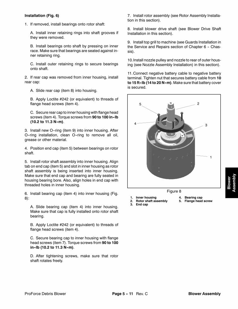
Rev. CProForce Debris Blower Page 5 -- 11 Blower Assembly
Installation (Fig. 6)
1. If removed, install bearings onto rotor shaft:
A. Install inner retaining rings into shaft grooves ifthey were removed.
B. Install bearings onto shaft by pressing on innerrace. Make sure that bearings are seated against in-ner retaining ring.
C. Install outer retaining rings to secure bearingsonto shaft.
2. If rear cap was removed from inner housing, installrear cap:
A. Slide rear cap (item 8) into housing.
B. Apply Loctite #242 (or equivalent) to threads offlange head screws (item 4).
C. Secure rear cap to inner housingwith flange headscrews (item 4). Torque screws from 90 to 100 in--lb(10.2 to 11.3 N--m).
3. Install new O--ring (item 9) into inner housing. AfterO--ring installation, clean O--ring to remove all oil,grease or other material.
4. Position end cap (item 5) between bearings on rotorshaft.
5. Install rotor shaft assembly into inner housing. Aligntab on end cap (item 5) and slot in inner housing as rotorshaft assembly is being inserted into inner housing.Make sure that end cap and bearing are fully seated inhousing bearing bore. Also, align holes in end cap withthreaded holes in inner housing.
6. Install bearing cap (item 4) into inner housing (Fig.8):
A. Slide bearing cap (item 4) into inner housing.Make sure that cap is fully installed onto rotor shaftbearing.
B. Apply Loctite #242 (or equivalent) to threads offlange head screws (item 4).
C. Secure bearing cap to inner housing with flangehead screws (item 7). Torque screws from 90 to 100in--lb (10.2 to 11.3 N--m).
D. After tightening screws, make sure that rotorshaft rotates freely.
7. Install rotor assembly (see Rotor Assembly Installa-tion in this section).
8. Install blower drive shaft (see Blower Drive ShaftInstallation in this section).
9. Install top grill to machine (see Guards Installation inthe Service and Repairs section of Chapter 6 -- Chas-sis).
10.Install nozzle pulley and nozzle to rear of outer hous-ing (see Nozzle Assembly Installation) in this section).
11.Connect negative battery cable to negative batteryterminal. Tighten nut that secures battery cable from 10to 15 ft--lb (14 to 20N--m). Make sure that battery coveris secured.
1. Inner housing2. Rotor shaft assembly3. End cap
4. Bearing cap5. Flange head screw
Figure 8
2
1
34
5
Blower
Assem
bly

ProForce Debris BlowerPage 5 -- 12Blower Assembly
Nozzle Assembly
1. Nozzle2. Nozzle clamp3. V belt4. Housing assembly5. Flat washer (10 used)6. R--clamp7. Nozzle motor8. Motor bracket9. Cap screw (3 used)10. Drive pulley
11. Lock nut12. Cap screw (2 used)13. Belt guard14. Flange head screw (2 used)15. Flat washer (2 used per bearing)16. Cap screw17. Flange nut (2 used)18. Flange nut19. Leaf spring
20. Bearing21. Cap screw (2 used)22. Flange nut (2 used)23. Shoulder bolt24. Lock nut25. Nozzle pulley26. Nozzle guide (4 used)27. Lock nut28. Socket head screw
Figure 9
FRONT
RIGHT
1
3
2
6
4
15
16
18
20
7
8
9
1011
12
1314
17
19
20
21
22
2315
5
24
16
20
25
26
28
27
45 to 50 in--lb(5.1 to 5.6 N--m)
NOTE: For service information on the nozzle motor(item 7), refer to the Service and Repairs section ofChapter 4 -- Electrical System.
Removal (Fig. 9)
1. Position machine on a firm, level surface. Make sureengine is stopped and remove key from the ignitionswitch. Chock wheels to prevent machine from moving.
2. To prevent unexpected machine operation, discon-nect the negative battery cable from the battery terminal(see Battery Service in the Service and Repairs sectionof Chapter 4 -- Electrical System). Position discon-nected negative cable away from the negative batteryterminal.
3. Loosen socket head screw and lock nut that securesends of nozzle clamp. Remove clamp from nozzle andnozzle pulley.
4. Remove nozzle from outer housing.
5. Remove two (2) cap screws (item21) and flangenuts(item 22) that secure leaf spring to motor bracket. Re-move leaf spring assembly and flat washers (item 5)from bracket. If necessary, remove bearing from leafspring (Fig. 11).
6. Loosen two (2) flange head screws (item 14) andflange nuts that secure nozzle motor bracket to outerhousing (Fig. 10). Rotate bracket and nozzle motor toloosen v--belt.

ProForce Debris Blower Page 5 -- 13 Blower Assembly
7. Loosen cap screws and flange nuts that secure beltguard (item 13), route v--belt from behind guard andcarefully remove belt from machine.
8. If necessary, remove nozzle guides, pulley bearingsand nozzle pulley from outer housing using Figures 9and 12 as guides.
Installation (Fig. 9)
1. If removed, install nozzle pulley, pulley bearings andnozzle guides using Figures 9 and 12 as guides.
2. Place v--belt in nozzle pulley, route behind belt guard(item 13) and install belt on motor pulley.
3. With a 3/8 in. drive torque wrench, pivot the motorbracket from 200 to 230 in--lb (23 to 25 N--m) to set v--belt tension (Fig. 10). Do not over tension belt. Holdbracket with the torque wrench and tighten two (2)flange head screws and flange nuts to secure belt ad-justment and nozzle motor bracket.
4. Center belt guard around v--belt. Tighten cap screwsand flange nuts to secure belt guard to machine.
5. If bearing was removed from leaf spring (Fig. 11),position bearing to leaf spring and secure with shoulderbolt and lock nut.
NOTE: When installing the leaf spring assembly, theleaf spring bearingmounting loops should be orientatedup.
6. Position leaf spring assembly and flat washers (item5) to bracket. Make sure that five (5) washers are placedbetween spring and bracket at eachmounting hole. Thebearing on the leaf spring should be centered on the out-side of the v--belt. Secure leaf spring to motor bracketwith two (2) cap screws (item 21) and flange nuts (item22).
7. Fit nozzle and nozzle clamp to pulley. Tighten sockethead screw and lock nut to secure nozzle to pulley.Torque fasteners from 45 to 50 in--lb (5.1 to 5.6 N--m).
8. Connect negative battery cable to negative batteryterminal. Tighten nut that secures battery cable from 10to 15 ft--lb (14 to 20N--m). Make sure that battery coveris secured.
1. Drive pulley2. Leaf spring assembly
3. Flange head screw4. Torque wrench access
Figure 10
1
2
3
3
4
1. Leaf spring2. Lock nut
3. Shoulder bolt4. Bearing
Figure 11
1
3
2
4
UP
1. Outer housing2. Nozzle pulley3. Cap screw
4. Nozzle guide (4 used)5. Flange nut6. Spacer
Figure 12
1
3
2
5
4
6
6
Blower
Assem
bly

Rev. C ProForce Debris BlowerPage 5 -- 14Blower Assembly
Inner Housing Assembly
1. Inlet bell2. Retaining ring3. Wave washer (up to 3 used)4. Front cap5. Nut (LH thread)6. Spacer7. Rotor assembly8. Washer (as needed)
9. Woodruff key10. Stator vane (24 used)11. Carriage screw (2 used)12. Outer housing13. Flange head screw (24 used)14. Cap screw (8 used)15. Flange head screw (8 used)16. Nozzle pulley
17. Cap screw (2 used per guide)18. Nozzle guide (4 used)19. Flange nut (16 used)20. Fan housing mount (2 used)21. Carriage screw (2 used)22. Flange nut (4 used)23. Inner housing assembly24. Spacer (2 used per guide)
Figure 13
1
14
32
4
5
67
12
9
10
11
8
1315
16
18
19
17
20
21
FRONT
RIGHT
Loctite #242
22
23
24
tighteningprocedure
10 to 20 in--lb(1.2 to 2.2 N--m)
90 to 100 in--lb(10.2 to 11.2 N--m)
See text for
SERIAL NUMBER BELOW 310000000 SHOWN
NOTE: The rotor shaft and bearings can be servicedwithout removing inner housing (item 23) from machine(see Rotor Shaft in this section). For replacement of theinner housing, stator vanes (item 10) or outer housing(item 12), the following procedure is necessary.
NOTE: ProForce Blowers have used three (3)methodsof securing the inner and outer housings. On machineswith serial number below 310000000 (Fig. 13), the innerhousing is attached directly to the outer housing.Onma-chines with serial number from 310000000 to313000000, a fin spacer and possibly additional thinspacers exist between the inner housing flanges and theouter housing (Fig. 14). Machines with serial numberabove 313000000 use four (4) fin mounts with finspacers and possibly additional thin spacers that are se-cured between inner housing and outer housing (Fig.15). Refer to correct illustration when removing and in-stalling inner and outer housings.

Rev. CProForce Debris Blower Page 5 -- 15 Blower Assembly
Removal (Fig. 13)
1. Position machine on a firm, level surface. Make sureengine is stopped and remove key from the ignitionswitch. Chock wheels to prevent machine from moving.
2. To prevent unexpected machine operation, discon-nect the negative battery cable from the battery terminal(see Battery Service in the Service and Repairs sectionof Chapter 4 -- Electrical System). Position discon-nected negative cable away from the negative batteryterminal.
3. Remove nozzle and nozzle pulley from rear of outerhousing (seeNozzleAssemblyRemoval in this section).
4. Remove top grill to allow access to blower assembly(see Guards Removal in the Service and Repairs sec-tion of Chapter 6 -- Chassis).
5. Remove blower drive shaft frommachine (see Blow-er Drive Shaft Removal in this section).
6. Remove rotor assembly (see Rotor Assembly Re-moval in this section).
7. Remove cap screws and flange nuts that secure out-er housing to fan housing mounts (item 20).
CAUTION
To prevent personal injury, make sure that fanhousing assembly is properly supported as it isremoved from the machine. Assembly weighsapproximately 70 pounds (31.8 kg).
8. Lift fan housing assembly from machine and set onworkbench with rotor shaft pointing straight up (Fig. 17).
9. Place inner housing on two (2) supports (2” x 4” orequivalent). Then, place 9/16” (14.3 mm) thick supportbetween supports and outer housing (Fig. 16). This pro-cess will support fan housing assembly to prevent unex-pected shifting of any components during disassembly.
10.Loosen, but do not remove, eight (8) screws (item15) that secure inner housing to outer housing.
11.Remove flange head screw (item 13) that secureseach stator vane (item 10) to outer housing. Carefully tiltvane to free vane lugs from inner housing and removevane from assembly. Repeat for all twenty four (24)vanes. Inspect each vane to make sure that mountinglugs and screw threads are in good condition. Replaceany vane that shows signs of damage or wear.
12.Fully remove screws (item 15) that secure innerhousing to outer housing.
1. Inner housing assembly2. Stator vane (24 used)3. Fin spacer (4 used)4. Thin spacer (as needed)
5. Flange screw (8 used)6. Flange screw (24 used)7. Outer housing
Figure 14
SERIAL NUMBER
2
3
6
1
57
4
FROM 310000000TO 313000000
1. Inner housing2. Outer housing3. Fin spacer (4 used)
4. Thin spacer (as needed)5. Fin mount (4 used)6. Cap screw (8 used)
Figure 15
23
6
1
5
4
SERIAL NUMBERABOVE 313000000
Loctite #242
1. Support2. 9/16” support
3. Outer housing4. Mounting holes
Figure 16
2
3
1
4
Blower
Assem
bly

Rev. C ProForce Debris BlowerPage 5 -- 16Blower Assembly
13.If equipped (machines with serial numbers above310000000), locate and retrieve fin mounts, fin spacersand thin spacers from between inner housing and outerhousing (Fig. 14 or 15). Note location of these compon-ents for assembly purposes.
14.Lift inner housing assembly out of the outer housing.
15.If necessary, disassemble inner housing assembly(see Rotor Shaft in this section).
Installation (Fig. 13)
1. Assemble inner housing if it was disassembled (seeRotor Shaft in this section).
2. Place inner housing assembly with the rotor shaftpointing upwards onto two (2) supports (2” x 4” or equiv-alent). Carefully lower outer housing around inner hous-ing assembly. Then, place 9/16” (14.3mm) thick supportbetween supports and outer housing (Fig. 16). This pro-cess should allow alignment of mounting holes in innerhousing flanges to outer housing.
3. On machines with serial numbers above310000000, install fin mounts, fin spacers and thinspacers (if equipped) between inner housing and outerhousing (Fig. 14 or 15).
NOTE: When assembling inner and outer housings, donot fully tighten any screws until all screws are installedto inner housing flanges and stator vanes. Also, usehand tools rather than air impact tools during assembly.
4. Onmachines with serial numbers above 313000000(Fig. 15), apply Loctite #242 (or equivalent) to threadsof screws used to secure inner and outer housings.
5. Make sure that holes in inner housing flanges alignwith outer housing holes. Install and finger tighten eight(8) screws (item 15) into threads of inner housingflanges. Do not fully tighten screws at this time.
6. Install stator vanes to inner and outer housing:
A. Position a vanebetween inner and outer housing.Make sure that rounded end of vane is orientated to-ward rotor shaft (Fig. 17).
B. Tilt vane and engage vane lugs to inner housingholes. While keeping vane lugs in inner housingholes, rotate vane to align threaded hole of vanewithouter housing hole.
C. Install and finger tighten flange head screw (item12) into threads of vane. Do not fully tighten screw atthis time.
D. Repeat process for all twenty--four (24) vanes.
1. Outer housing2. Inner housing assembly3. Stator vane (24 used)
4. Flange head screw5. Flange head screw
Figure 17
ROUNDED
DISCHARGEEND
INTAKEEND
END
23
1
4
5
7. Tighten fasteners in the following order to secure as-sembly:
A. Use nutdriver to hand tighten the eight (8) screws(item 15) that secure inner housing flanges to outerhousing. Use a crossing pattern while tightening thescrews.
B. Use nutdriver to hand tighten the flange headscrews (item 12) that secure the twenty--four (24)stator vanes to outer housing. Use a crossing patternwhile tightening the screws.
C. Torque flange head screws (item 15) that secureinner housing flanges to outer housing from 90 to100 in--lb (10.2 to 11.2N--m). Use a crossing patternwhile torquing the screws.
IMPORTANT: DO NOT overtighten screws thatsecure stator vanes to outer housing. If screwsare overtightened, threads in vanes could bedamaged.
D. Torque screws (item 12) that secure stator vanesto outer housing from 10 to 20 in--lb (1.2 to 2.2N--m). Use a crossing pattern while torquing thescrews.

Rev. CProForce Debris Blower Page 5 -- 17 Blower Assembly
CAUTION
To prevent personal injury, make sure that outerhousing assembly is properly supported as it ispositioned to machine. Assembly weighsapproximately 70 pounds (31.8 kg).
8. Position outer housing assembly tomachine. Secureouter housing to fan housing mounts with cap screwsand flange nuts.
9. Install rotor assembly (see Rotor Assembly Installa-tion in this section).
10.Install blower drive shaft (see Blower Drive ShaftInstallation in this section).
11. Install top grill to machine(see Guards Installation inthe Service and Repairs section of Chapter 6 -- Chas-sis).
12.Install nozzle pulley and nozzle to rear of outer hous-ing (see Nozzle Assembly Installation in this section).
13.Connect negative battery cable to negative batteryterminal. Tighten nut that secures battery cable from 10to 15 ft--lb (14 to 20N--m). Make sure that battery coveris secured.
Blower
Assem
bly

ProForce Debris BlowerPage 5 -- 18Blower Assembly
This page is intentionally blank.

Rev. BProForce Debris Blower Page 6 -- 1 Chassis
Chapter 6
ChassisTable of ContentsSPECIFICATIONS 2. . . . . . . . . . . . . . . . . . . . . . . . . . . . .GENERAL INFORMATION 3. . . . . . . . . . . . . . . . . . . . .Operator’s Manual 3. . . . . . . . . . . . . . . . . . . . . . . . . .Securing ProForce Debris Blower to Tow Vehicle 3Electrical Power 3. . . . . . . . . . . . . . . . . . . . . . . . . . . . .
SERVICE AND REPAIRS 4. . . . . . . . . . . . . . . . . . . . . .Wheels 4. . . . . . . . . . . . . . . . . . . . . . . . . . . . . . . . . . . .Wheel Hubs and Bearings 6. . . . . . . . . . . . . . . . . . . .Guards 10. . . . . . . . . . . . . . . . . . . . . . . . . . . . . . . . . . .
Chassis

Rev. B ProForce Debris BlowerPage 6 -- 2Chassis
Specifications
Item Description
TiresSize 20 x 10 -- 8, 4 Ply, TubelessPressure 14 PSI (96.5 kPa)
Wheel Lug Nut Torque 70 to 90 ft--lb (95 to 122 N--m)

ProForce Debris Blower Page 6 -- 3 Chassis
General Information
Operator’s Manual
The Operator’s Manual provides information regardingthe operation, general maintenance and maintenanceintervals for your ProForce Debris Blower. Refer to theOperator’s Manual for additional information when ser-vicing the machine.
Securing ProForce Debris Blower to Tow Vehicle
While operating or servicing the ProForce blower, makesure that hitch pin is properly positioned in tow vehiclehitch and blower tongue. Hitch pin should be securedwith hairpin clip (Fig. 1).
1. Tow vehicle hitch2. Hitch pin
3. Hairpin clip
Figure 1
3
21
Electrical Power
Electrical power to ProForce Debris Blower compo-nents is controlled by the Remote Control Module. Tomake sure thatmachine operation does not occur unex-pectedly, disconnect the negative battery cable from thebattery before performing any machine service (seeBattery Service in the Service and Repairs section ofChapter 4 -- Electrical System).
Reattach the disconnected negative battery cable asthe last step in any repair. Secure cable with flange nut.Torque nut from 10 to 15 ft--lb (14 to 20 N--m).
Chassis

Rev. B ProForce Debris BlowerPage 6 -- 4Chassis
Service and Repairs
Wheels
1. Main frame2. Engine
3. Wheel hub assembly4. Wheel and tire assembly
5. Lug nut (4 used per wheel)
Figure 2
FRONT
RIGHT
1
2
3
4
5
70 to 90 ft--lb(95 to 122 N--m)

Rev. BProForce Debris Blower Page 6 -- 5 Chassis
Wheel Removal (Fig. 2)
1. Have ProForce Debris Blower attached to tow ve-hicle and park machines on a level surface. Engage ve-hicle parking brake, stop engine and remove key fromthe ignition switch. Make sure that blower engine is off.Chock wheels to prevent movement of either machine.
2. Toprevent unexpectedblower operation, disconnectthe negative battery cable from the battery terminal (seeBattery Service in the Service and Repairs section ofChapter 4 -- Electrical System). Position disconnectednegative cable away from the negative battery terminal.
3. Loosen but do not remove four (4) lug nuts that se-cure wheel to be removed.
4. Jack or hoist ProForce blower from ground and sup-port raised machine with jack stands (see Operator’sManual and Jacking Instructions in Chapter 1 -- Safety).
5. Remove lug nuts andpull wheel frommachinewheelhub.
Wheel Installation (Fig. 2)
1. Position wheel to wheel hub on raised machine.
2. Secure wheel to ProForce blower with four (4) lugnuts.
Failure to maintain proper lug nut torque couldresult in failure or loss ofwheel andmay result inpersonal injury.
WARNING
3. Lower machine to ground. Alternately torque lugnuts from 70 to 90 ft--lb (95 to 122 N--m).
4. Connect negative battery cable to negative batteryterminal. Tighten nut that secures battery cable from 10to 15 ft--lb (14 to 20N--m). Make sure that battery coveris secured.
Chassis

Rev. B ProForce Debris BlowerPage 6 -- 6Chassis
Wheel Hubs and Bearings
Figure 31. Axle (2 used)2. Grease seal3. Bearing cone (2 used per axle)4. Bearing cup (2 used per axle)5. Wheel hub
6. Lug screw (4 used per hub)7. Tab washer8. Nut retainer9. Flange nut (3 used per axle)
10. Cotter pin11. Jam nut12. Dust cap13. Carriage screw (3 used per axle)
See text fortightening procedure
1
6
7
32
5
4
8
9
10
11
12
3
FRONT
RIGHT
13
SERIAL NUMBER BELOW 310000000 SHOWN
27 to 33 ft--lb(37 to 44 N--m)
NOTE: Machineswith serial number above310000000either use an axle mount that is fastened to the frame(Fig. 4) or have a suspension axle for road ready ma-chines (Fig. 5). Wheel hub and bearing service is thesame for all axle types.
Disassembly (Fig. 3)
1. Have ProCore Processor attached to tow vehicleand park machines on a level surface. Engage vehicleparking brake, stop engine and remove key from theignition switch. Make sure that Processor engine is off.Chock wheels to prevent movement of either machine.

Rev. BProForce Debris Blower Page 6 -- 7 Chassis
2. Toprevent unexpectedblower operation, disconnectthe negative battery cable from the battery terminal (seeBattery Service in the Service and Repairs section ofChapter 4 -- Electrical System). Position disconnectednegative cable away from the negative battery terminal.
3. Jack or hoist blower from ground and support withjack stands (see Operator’s Manual and Jacking In-structions in Chapter 1 -- Safety).
4. Remove wheel assembly (see Wheel Removal inthis section).
5. Carefully pry dust cap from wheel hub.
6. Straighten cotter pin and remove from axle spindle.
7. Removenut retainer, jamnut and tabwasher that se-curewheel hub tospindle.Slidewheel hubwithbearingsfrom spindle.
8. Disassemble wheel hub:
A. Remove grease seal from the wheel hub takingcare to not damage the hub bore. Discard seal.
B. Remove bearing cones from both sides of wheelhub. Clean bearings in solvent. Clean inside of hub.
C. If necessary, remove bearing cups from hub.
D. Inspectwheel bearings.Check thebearingconesand bearing cups for wear, pitting or other damage.Replace worn or damaged parts.
E. If necessary, press lug screws from hub.
9. Inspect axle spindle for wear or damage. Replaceaxle if necessary. Refer to appropriate axle illustrationfor fastener torque values.
Assembly (Fig. 3)
1. Thoroughly clean all wheel hub components beforeassembly.
2. Assemble wheel hub:
A. If bearing cups were removed from the wheelhub, press inner and outer cups into the hub untilthey seat against the hub shoulder.
B. Fill hub approximately 50% full of grease.
C. Pack both bearing cones with grease. Installgreased inner bearing cone into the cup on inboardside of the wheel hub.
IMPORTANT: The grease seal must be pressedin so it is flush with the end of the hub. The lip ofthe seal must face the inner bearing.
D. Lubricate the insideof newgrease seal andpressit into the wheel hub.
E. If lug screws were removed from hub, pressscrews fully intohub.Makesure that lug screw flangeis pressed fully to hub surface.
1. Frame2. Carriage screw3. Axle4. Flange nut
5. Hub assembly6. Lock nut7. Carriage screw8. Axle mount
Figure 4
2 3
6
8
1
5
7
4
SERIAL NUMBER ABOVE 310000000 SHOWN
27 to 33 ft--lb(37 to 44 N--m)
27 to 33 ft--lb(37 to 44 N--m)
1. Frame2. Carriage screw3. Axle
4. Lock nut5. Hub assembly
Figure 5
2
3
15
4
SUSPENSION AXLE SHOWN
67 to 83 ft--lb(91 to 112 N--m)
Chassis

Rev. B ProForce Debris BlowerPage 6 -- 8Chassis
3. Install the wheel hub onto the axle spindle takingcare to not damage grease seal in hub.
4. Install greased outer bearing cone, tab washer andjam nut onto spindle shaft.
5. While rotating thewheel hub by hand, torque the jamnut from 75 to 180 in-lb (8.5 to 20.3 N--m) to seat bear-ings. Loosen nut until it is away from tabwasher andhubhas end play. Finally, while rotating hub, tighten jam nutfrom 15 to 20 in--lbs (1.7 to 2.3 N--m).
6. Install nut retainer and cotter pin to secure jam nut.Install dust cap to hub.
Failure to maintain proper lug nut torque couldresult in failure or loss ofwheel andmay result inpersonal injury.
WARNING
7. Install wheel assembly (seeWheel Installation in thissection).
8. Carefully lower machine to ground. Make sure toproperly torque wheel lug nuts from 70 to 90 ft--lb (95to 122 N--m).
9. Connect negative battery cable to negative batteryterminal. Tighten nut that secures battery cable from 10to 15 ft--lb (14 to 20N--m). Make sure that battery coveris secured.

Rev. BProForce Debris Blower Page 6 -- 9 Chassis
This page is intentionally blank.
Chassis

Rev. B ProForce Debris BlowerPage 6 -- 10Chassis
Guards
Figure 61. Cap screw (2 used)2. Washer (2 used)
3. Flange nut (2 used)4. Top grill
5. Side grill6. Flange head screw (2 used)
FRONT
RIGHT
1
2
3
4
5
1
2
3
6
6
SERIAL NUMBER BELOW 311000000 SHOWN

Rev. BProForce Debris Blower Page 6 -- 11 Chassis
Removal
1. Park machine on a level surface. Make sure engineis OFF. Chock wheels to prevent machine frommoving.
2. To prevent unexpected machine operation, discon-nect the negative battery cable from the battery terminal(see Battery Service in the Service and Repairs sectionof Chapter 4 -- Electrical System). Position discon-nected negative cable away from the negative batteryterminal.
CAUTION
The engine may be hot. Allow engine to cool be-fore removing guards from machine.
3. Remove guards frommachine as needed using Fig.6 or 7 as a guide.
NOTE: Machineswith serial number above 311000000use a muffler mount to support the front of the top grill(Fig. 7). Removal of the muffler mount on these ma-chines requires removal of the blower driveshaft or en-gine.
Installation
1. Install removed guards from machine using Figs. 6or 7 as a guide.
1. Cap screw (2 used)2. Washer (2 used)3. Flange screw (2 used)4. Flange nut (2 used)
5. Muffler mount6. Top grill7. Tinnerman nut (2 used)
Figure 7
1
2
3 4
5
4
66
7
SERIAL NUMBER ABOVE 311000000 SHOWN
Chassis

Rev. B ProForce Debris BlowerPage 6 -- 12Chassis
This page is intentionally blank.

Rev. CProForce Debris Blower Electrical DiagramsPage 7 -- 1
Chapter 7
Electrical Diagrams
Table of ContentsELECTRICAL SCHEMATICSModel 44538 with Serial Number Below310000000 3. . . . . . . . . . . . . . . . . . . . . . . . . . . . . . .
Models 44538 and 44539 with Serial NumberFrom 310000000 to 311999999 & Model 44542(all Serial Numbers) 4. . . . . . . . . . . . . . . . . . . . . . .
Models 44538 and 44539 with Serial NumberAbove 312000000 5. . . . . . . . . . . . . . . . . . . . . . . . .
ENGINE ELECTRICAL DIAGRAMSSerial Number Below 310000000 6. . . . . . . . . . . . .Serial Number Above 310000000 7. . . . . . . . . . . . .
CIRCUIT DRAWINGSControl Module Wake Up 8. . . . . . . . . . . . . . . . . . . . .Crank Circuits 9. . . . . . . . . . . . . . . . . . . . . . . . . . . . . .Run Circuits 10. . . . . . . . . . . . . . . . . . . . . . . . . . . . . . .Engine Speed Increase Circuits 11. . . . . . . . . . . . . . .Nozzle Rotation Circuits 12. . . . . . . . . . . . . . . . . . . .
WIRE HARNESS DRAWINGSModel 44538 with Serial Number Below310000000 14. . . . . . . . . . . . . . . . . . . . . . . . . . . . . .
Models 44538 and 44539 with Serial NumberFrom 310000000 to 311999999 & Model 44542(all Serial Numbers) 16. . . . . . . . . . . . . . . . . . . . . .
Models 44538 and 44539 with Serial NumberAbove 312000000 18. . . . . . . . . . . . . . . . . . . . . . . .
Electrical
Diagrams

ProForce Debris BlowerElectrical Diagrams Page 7 -- 2
This page is intentionally blank.

Rev. CPage 7 -- 3
GRAY
YELLOW
GREEN
BLUE
FUSIBLE
RED/YELLOW
WHITE
PINK
GREEN
RED
BLACK
RED/WHITE
RED
GREEN
RED/YELLOW
RED
GREEN
GREEN/BLACK
BLACK
ORANGE/BLACK
BLACK
BLUE
GREEN
PINK
BLACK
GRAYYELLOW/BLACK
GRAY
RED/WHITE
ENGINE
THROTTLE CONTROL
OIL PRESSURE SWITCH (GREEN)
ENGINE KILL (WHITE)
B+
START
FUEL SOLENOID OUT (RED)
FUEL SOLENOID (RED/WHITE)
GRAY
GRAYCOIL POWER
GRAY
BATTERYLINK
NOZZLE
INLINE FUSE (15A)
Electrical SchematicAll ground wires are black.
Below 310000000Model 44538 with Serial NumberProForce Debris Blower

Rev. CPage 7 -- 4
Electrical SchematicAll ground wires are black.
Model 44542 (all Serial Numbers)From 310000000 to 311999999
Models 44538 and 44539 with Serial NumberProForce Debris Blower
GREEN
BLUE
RED/YELLOW
WHITE
RED/WHITE
RED
GREEN
RED/YELLOW
RED/WHITE
GREEN/BLACKBLACK
ORANGE/BLACK
GRAY
GRAY
GREEN
PINK
BLUE
RED YELLOW
GRAY
GRAY
WHITE
GREEN
YELLOW
BROWN
BROWN
BROWNWHITE
WHITE
YELLOW
BROWN
BLUEGREENPINKBLACKGRAY
YELLOW/BLACK

Rev. CPage 7 -- 5
Electrical SchematicAll ground wires are black.
Above 312000000Models 44538 and 44539 with Serial NumberProForce Debris Blower
RED/WHITE
PINK
RED/YELLOW
GREEN
YELLOW
BROWNWHITE
YELLOWBROWNWHITE
BROWN
BROWNWHITE
TAN
YELLOWRED
RED/YELLOW
GREEN
RED
BLUE
ORANGE
GREEN
WHITE
BLACK
GREEN
YELLOW
BLACKPINK
BLACKPINK
YELLOW
BLACK
BLACK
BLACK
RED/WHITEPINK
GRAY
PINK
TAN
BLUE
TANGREENPINKBLACKGRAY

Rev. CPage 7 -- 6
Engine Electrical DiagramSerial Numbers Below 310000000
All ground wires are black.
DLA 2B (pin B DLA)
DLA 2A (pin C DLA)TXDiag Lamp Driver
GCU Power +12V
RXGROUNDSpeed InputShutdown
GROUND
DLA 1A (pin A DLA)
DLA 1B (pin D DLA)
12
345
67
89
1011
121314
AB
CD
AB
CD
WHITE
RED/YELLOW
RED
BLACK (GRD)
PINKBROWN
GRAY
ORANGEDIGITAL
RED/YELLOW
(30 A)
RED/W
HITE
GREEN
GRAY
RED MACHINE
WIREHARNESS
LINEARACTUATOR
(DLA)
GOVERNORCONTROL
UNIT(GCU)
NOTE: THE OIL PRESSURESWITCH IS NORMALLY OPENAND CLOSES WHEN ENGINEOIL PRESSURE EXISTS
ProForce Debris Blower

Rev. CPage 7 -- 7
Engine Electrical DiagramSerial Numbers Above 310000000
All ground wires are black.
ProForce Debris Blower
DLA 2B (pin B DLA)
DLA 2A (pin C DLA)TXDiag Lamp Driver
GCU Power +12V
RXGROUND
Speed Input
Shutdown
GROUND
DLA 1A (pin A DLA)
DLA 1B (pin D DLA)
12
34
5
67
89
10
11
121314
A
B
CD
A
B
CD
WHITE
RED/YELLOW
RED
BLACK (GRD)
PINKBROWN
GRAY
ORANGEDIGITAL MACHINEWIRE
HARNESS
LINEARACTUATOR
(DLA)
GOVERNORCONTROL
UNIT(GCU)
NOTE: THE OIL PRESSURESWITCH IS NORMALLY OPENAND CLOSES WHEN ENGINEOIL PRESSURE EXISTS
(30 A)
123456
123456
RED/YELLOW
RED/W
HITE
GREEN
BLU
E
RED

Rev. CPage 7 -- 8
GRAY
YELLOW
GREEN
BLUE
FUSIBLE
RED/YELLOW
WHITE
PINK
GREEN
RED
BLACK
RED/WHITE
RED
GREEN
RED/YELLOW
RED
GREEN
GREEN/BLACK
BLACK
ORANGE/BLACK
BLACK
BLUE
GREEN
PINK
BLACK
GRAYYELLOW/BLACK
GRAY
RED/WHITE
ENGINE
THROTTLE CONTROL
OIL PRESSURE SWITCH (GREEN)
ENGINE KILL (WHITE)
B+
START
FUEL SOLENOID OUT (RED)
FUEL SOLENOID (RED/WHITE)
GRAY
GRAYCOIL POWER
GRAY
BATTERYLINK
RUN
START
OFF
Control Module Wake Up
Power Current
Control Current
Indicator/Gauge Current
ProForce Debris Blower
Ignition Switch Turned to START
IGNITION SWITCH(ON ENGINE)
TURNED TO START
No Control Module LED’s Illuminated
Tested to Compl y
With FCC Standar dsFOR HOME OR OFFICE USE
Canada3575APFB1
Model: 44538
N 1 6 2 5
Made in U.S .A.
NOBUTTONSPRESSED
CONTROL MODULE
REMOTE TRANSMITTER
NOLED’s
ILLUMINATED
No Remote Transmitter Buttons Pressed
NOZZLE
INLINE FUSE (15A)
NOTE: THE DRAWING ON THIS PAGE USES THEELECTRICAL SCHEMATIC FROM A MACHINE WITHA SERIAL NUMBER BELOW 310000000 TO SHOW THEOPERATIONAL CIRCUITS.

Rev. CPage 7 -- 9
GRAY
YELLOW
GREEN
BLUE
FUSIBLE
RED/YELLOW
WHITE
PINK
GREEN
RED
BLACK
RED/WHITE
RED
GREEN
RED/YELLOW
RED
GREEN
GREEN/BLACK
BLACK
ORANGE/BLACK
BLACK
BLUE
GREEN
PINK
BLACK
GRAYYELLOW/BLACK
GRAY
RED/WHITE
ENGINE
THROTTLE CONTROL
OIL PRESSURE SWITCH (GREEN)
ENGINE KILL (WHITE)
B+
START
FUEL SOLENOID OUT (RED)
FUEL SOLENOID (RED/WHITE)
GRAY
GRAYCOIL POWER
GRAY
BATTERYLINK
START
RUNOFF
IGNITION SWITCH(ON ENGINE)
IN RUN POSITION
Crank Circuits
Power Current
Control Current
Indicator/Gauge Current
ProForce Debris Blower
Ignition Switch in RUN Position
Control Module LED’s Illuminated
Remote Transmitter ENGINE START Sequence Pressed
ENGINE STARTSEQUENCEPRESSED
Tested to Compl y
With FCC Standar dsFOR HOME OR OFFICE USE
Canada3575APFB1
Model: 44538
N 1 6 2 5
Made in U.S .A.
CONTROL MODULE
LED’SILLUMINATED
ON
ON
ENERGIZED
ENERGIZED
REMOTE TRANSMITTER
NOZZLE
ON
INLINE FUSE (15A)
NOTE: THE DRAWING ON THIS PAGE USES THEELECTRICAL SCHEMATIC FROM A MACHINE WITHA SERIAL NUMBER BELOW 310000000 TO SHOW THEOPERATIONAL CIRCUITS.

Rev. CPage 7 -- 10
GRAY
YELLOW
GREEN
BLUE
FUSIBLE
RED/YELLOW
WHITE
PINK
GREEN
RED
BLACK
RED/WHITE
RED
GREEN
RED/YELLOW
RED
GREEN
GREEN/BLACK
BLACK
ORANGE/BLACK
BLACK
BLUE
GREEN
PINK
BLACK
GRAYYELLOW/BLACK
GRAY
RED/WHITE
ENGINE
THROTTLE CONTROL
OIL PRESSURE SWITCH (GREEN)
ENGINE KILL (WHITE)
B+
START
FUEL SOLENOID OUT (RED)
FUEL SOLENOID (RED/WHITE)
GRAY
GRAYCOIL POWER
GRAY
BATTERYLINK
START
RUNOFF
IGNITION SWITCH(ON ENGINE)
IN RUN POSITION
Run Circuits
Power Current
Control Current
Indicator/Gauge Current
ProForce Debris Blower
Ignition Switch in RUN Position and Engine Running
Control Module LED’s Illuminated
No Remote Transmitter Buttons Being Pressed
NOBUTTONSPRESSED
Tested to Compl y
With FCC Standar dsFOR HOME OR OFFICE USE
Canada3575APFB1
Model: 44538
N 1 6 2 5
Made in U.S .A.
CONTROL MODULE
LED’SILLUMINATED
ON
ON
ENERGIZED
ENERGIZED
REMOTE TRANSMITTER
NOZZLE
INLINE FUSE (15A)
NOTE: THE DRAWING ON THIS PAGE USES THEELECTRICAL SCHEMATIC FROM A MACHINE WITHA SERIAL NUMBER BELOW 310000000 TO SHOW THEOPERATIONAL CIRCUITS.

Rev. CPage 7 -- 11
GRAY
YELLOW
GREEN
BLUE
FUSIBLE
RED/YELLOW
WHITE
PINK
GREEN
RED
BLACK
RED/WHITE
RED
GREEN
RED/YELLOW
RED
GREEN
GREEN/BLACK
BLACK
ORANGE/BLACK
BLACK
BLUE
GREEN
PINK
BLACK
GRAYYELLOW/BLACK
GRAY
RED/WHITE
ENGINE
THROTTLE CONTROL
OIL PRESSURE SWITCH (GREEN)
ENGINE KILL (WHITE)
B+
START
FUEL SOLENOID OUT (RED)
FUEL SOLENOID (RED/WHITE)
GRAY
GRAYCOIL POWER
GRAY
BATTERYLINK
START
RUNOFF
IGNITION SWITCH(ON ENGINE)
IN RUN POSITION
Engine Speed Increase Circuits
Power Current
Control Current
Indicator/Gauge Current
ProForce Debris Blower
Ignition Switch in RUN Position and Engine Running
Control Module LED’s Illuminated
Remote Speed Increase Button Being Pressed
SPEED
BUTTONPRESSED
Tested to Compl y
With FCC Standar dsFOR HOME OR OFFICE USE
Canada3575APFB1
Model: 44538
N 1 6 2 5
Made in U.S .A.
CONTROL MODULE
ILLUMINATED
ON
ON
ENERGIZED
ENERGIZED
REMOTE TRANSMITTER
LED’S
ON
INCREASE
PRESSED
NOZZLE
ON
INLINE FUSE (15A)
NOTE: THE DRAWING ON THIS PAGE USES THEELECTRICAL SCHEMATIC FROM A MACHINE WITHA SERIAL NUMBER BELOW 310000000 TO SHOW THEOPERATIONAL CIRCUITS.
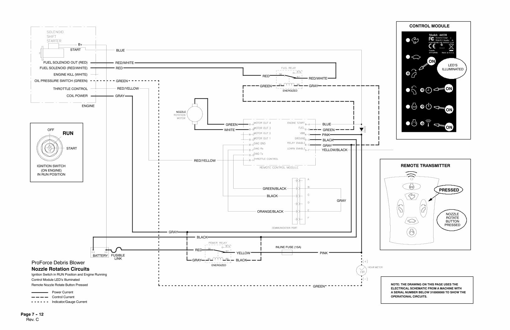
Rev. CPage 7 -- 12
GRAY
YELLOW
GREEN
BLUE
FUSIBLE
RED/YELLOW
WHITE
PINK
GREEN
RED
BLACK
RED/WHITE
RED
GREEN
RED/YELLOW
RED
GREEN
GREEN/BLACK
BLACK
ORANGE/BLACK
BLACK
BLUE
GREEN
PINK
BLACK
GRAYYELLOW/BLACK
GRAY
RED/WHITE
ENGINE
THROTTLE CONTROL
OIL PRESSURE SWITCH (GREEN)
ENGINE KILL (WHITE)
B+
START
FUEL SOLENOID OUT (RED)
FUEL SOLENOID (RED/WHITE)
GRAY
GRAYCOIL POWER
GRAY
BATTERYLINK
START
RUNOFF
IGNITION SWITCH(ON ENGINE)
IN RUN POSITION
Nozzle Rotation Circuits
Power Current
Control Current
Indicator/Gauge Current
ProForce Debris Blower
Ignition Switch in RUN Position and Engine Running
Control Module LED’s Illuminated
Remote Nozzle Rotate Button Pressed
NOZZLE
BUTTONPRESSED
Tested to Compl y
With FCC Standar dsFOR HOME OR OFFICE USE
Canada3575APFB1
Model: 44538
N 1 6 2 5
Made in U.S .A.
CONTROL MODULE
ILLUMINATED
ON
ON
ENERGIZED
ENERGIZED
REMOTE TRANSMITTER
LED’SON
ROTATE
PRESSED
NOZZLE
ON
INLINE FUSE (15A)
NOTE: THE DRAWING ON THIS PAGE USES THEELECTRICAL SCHEMATIC FROM A MACHINE WITHA SERIAL NUMBER BELOW 310000000 TO SHOW THEOPERATIONAL CIRCUITS.

Rev. CPage 7 -- 13
This page is intentionally blank.

Rev. CPage 7 -- 14
Wire Harness Drawing
NOZZLEROTATION
MOTOR
ProForce Debris Blower
Below 310000000Model 44538 with Serial Number

Rev. CPage 7 -- 15
BLUE
RED
GREEN
GREEN
WHITE
RED
GREEN
GREEN
PINK
GRAY
RED/W
HITE
BLACK
GRAY
BLA
CK
YELLOW
PINK
GRAY
BLUE
PINKBLACKGRAY
YELLOW/BLACK
WHITE
BLACKORANGE/BLACK
GREEN/BLACKRED/YELLOW
BLU
E
PINK
GREEN
NOZZLEROTATIONMOTOR
Wire Harness Diagram
ProForce Debris Blower
Below 310000000Model 44538 with Serial Number

Rev. CPage 7 -- 16
Wire Harness Drawing
ProForce Debris Blower
Model 44542 (all Serial Numbers)From 310000000 to 311999999
Models 44538 and 44539 with Serial Number

Rev. CPage 7 -- 17
Wire Harness Diagram
GREEN
GREENBLUE
PINKBLACKGRAY
YELLOW/BLACK
WHITE
BLACKORANGE/BLACKGREEN/BLACK
RED/YELLOW
GRAY
GRAY
GREEN
YELLOW
RED
BLUE
BLUE
RED/WHITE
GRAY
RED/W
HITE
GRAY
ProForce Debris Blower
Model 44542 (all Serial Numbers)From 310000000 to 311999999
Models 44538 and 44539 with Serial Number

Rev. CPage 7 -- 18
Wire Harness Drawing
ProForce Debris Blower
Above 312000000Models 44538 and 44539 with Serial Number
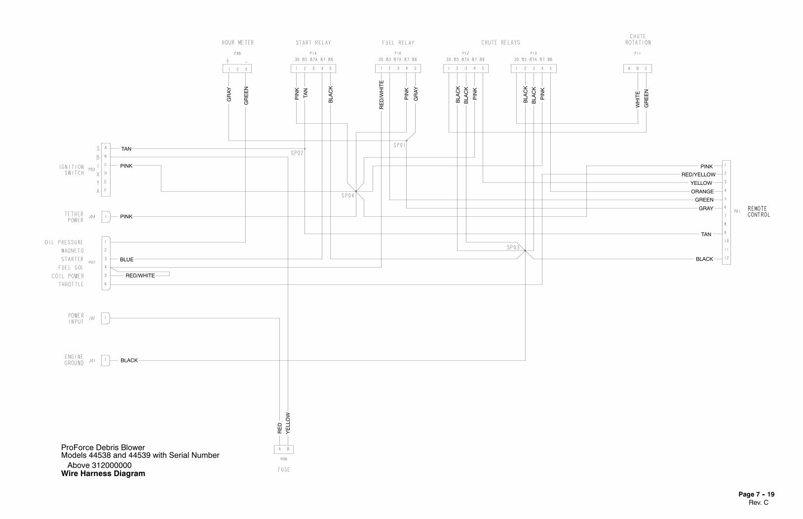
Rev. CPage 7 -- 19
Wire Harness Diagram
ProForce Debris Blower
Above 312000000Models 44538 and 44539 with Serial Number
GRAY
GRAY
YELLOW
RED
RED/WHITE
BLACK
TAN
GRAY
GREEN
ORANGE
YELLOW
RED/YELLOW
PINK
GREEN
WHITE
PINK
BLA
CK
BLA
CK
PINK
BLA
CK
BLA
CK
PINK
RED/W
HITE
BLA
CK
GREEN
TAN
PINK
TAN
PINK
PINK
BLUE
BLACK