Embed Size (px)
Citation preview
PROFILE System DescriptionTechnology and Application
IPROFILE
Introduction Application profiles guarantee fast and smooth planning, commissioning, and operation of modern automation systems involving devices and systems of a wide range of manufacturers. In the production industry, in particular, the proxy function block technology is very beneficial when creating and using application profiles. The document is targeted mainly at planners, project engineers, integrators, but also end users.
II PROFILE
Table of Contents
1. APPLICATION PROFILES ....................... 1
1.1. INTRODUCTION ................................... 1 1.2. CLASSIFICATION OF THE APPLICATION
PROFILES ........................................... 1 1.3. THE VIEW OF THE PLC PROGRAMMER .. 2 1.4. FUNCTION BLOCKS.............................. 3 1.5. THE “PROXY FB” CONCEPT FOR
PRODUCTION AUTOMATION................... 4 1.6. FUNCTION BLOCKS AS
REPRESENTATIVES (PROXY FB) ALSO FOR FIELD DEVICES ..................... 4
1.7. PROCEDURES FOR DEVELOPING AND
IMPLEMENTING PROFILE
SPECIFICATIONS.................................. 5
1.8. CERTIFICATION....................................5 1.9. PI APPLICATION PROFILES
(OVERVIEW) ........................................5 1.10. BENEFITS OF DEVICE PROFILES .............6
2. PROFIBUS & PROFINET INTERNATIONAL (PI) ...............................7
2.1. RESPONSIBILITIES OF PI.......................7 2.2. TECHNOLOGY DEVELOPMENT................7 2.3. TECHNICAL SUPPORT ...........................7 2.4. CERTIFICATION....................................7 2.5. TRAINING............................................7 2.6. INTERNET ...........................................7
1PROFILE
1. Application profiles
Application profiles guarantee fast and smooth planning, commissioning, and operation of mod-ern automation systems involving devices and systems of a wide range of manufacturers. In the production industry, in particular, the proxy func-tion block technology is very beneficial when cre-ating and using application profiles. The docu-ment is targeted mainly at planners, project engi-neers, integrators, but also end users.
1.1. Introduction The entry of fieldbus technology into automation engineering was one of the prerequisites for using the diverse functions and information available in modern field devices for flexible and sophisticated automation tasks, for which conventional signal transmission (digital 0-24 V, analog, e.g., 0-10 V /4-20 mA) performance is no longer adequate. Fieldbus technologies – as well as the new Ethernet-based solutions – provide the resources for this additional data communication. These involve data communication connections between the sensor/actuator level, open-loop/closed-loop control level, and plant management level, in which the various bus nodes are linked for com-munication purposes via bus protocols. Configu-ration data, parameter assignment data, in-put/output data, and diagnostic data are transmit-ted digitally according to certain rules. These rules specify aspects, such as data types, system startup, cyclical data exchange, and error re-sponses, and are standardized in the form of “bus communication profiles” in IEC 61158. For smooth “correspondence” among the participating bus nodes (field devices, controllers, engineering sta-tions, and operator control and monitoring sta-tions) of different manufacturers in the system, these devices must match up in terms of their basic communication functions and services; they must “speak the same language” and use the same terms. If such standardization is lacking, the practical result is proprietary, singular solutions, which can act together in one automation system
only after significant effort – a situation that is no longer acceptable to users.
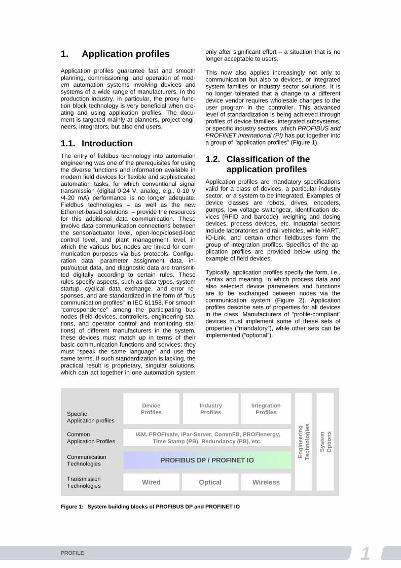
This now also applies increasingly not only to communication but also to devices, or integrated system families or industry sector solutions. It is no longer tolerated that a change to a different device vendor requires wholesale changes to the user program in the controller. This advanced level of standardization is being achieved through profiles of device families, integrated subsystems, or specific industry sectors, which PROFIBUS and PROFINET International (PI) has put together into a group of "application profiles" (Figure 1).
1.2. Classification of the application profiles
Application profiles are mandatory specifications valid for a class of devices, a particular industry sector, or a system to be integrated. Examples of device classes are robots, drives, encoders, pumps, low voltage switchgear, identification de-vices (RFID and barcode), weighing and dosing devices, process devices, etc. Industrial sectors include laboratories and rail vehicles, while HART, IO-Link, and certain other fieldbuses form the group of integration profiles. Specifics of the ap-plication profiles are provided below using the example of field devices.
Typically, application profiles specify the form, i.e., syntax and meaning, in which process data and also selected device parameters and functions are to be exchanged between nodes via the communication system (Figure 2). Application profiles describe sets of properties for all devices in the class. Manufacturers of “profile-compliant” devices must implement some of these sets of properties (“mandatory”), while other sets can be implemented (“optional”).
Communication Technologies
SpecificApplication profiles
Transmission Technologies
PROFIBUS DP / PROFINET IO
Wired WirelessOptical
Device Profiles
CommonApplication Profiles
I&M, PROFIsafe, iPar-Server, CommFB, PROFIenergy,Time Stamp (PB), Redundancy (PB), etc.
Industry Profiles
Integration Profiles
En
gin
eeri
ng
Te
ch
no
log
ies
Sy
ste
mO
pti
on
s
Figure 1: System building blocks of PROFIBUS DP and PROFINET IO
2 PROFILE
In particular, profile specifications include:
Uniform term definitions Functional device structures or architectures
(device models) Data structures for the process inputs/outputs
(switching states, measured values or manipu-lated variable values, product information, etc.)
Structure and function of the field device pa-rameters to be communicated (e.g., configura-tions, setpoints and actual values, units, limits, measuring ranges) by means of attributes such as name, data type, value range, access rights, etc.
Profile-specific identification and maintenance information
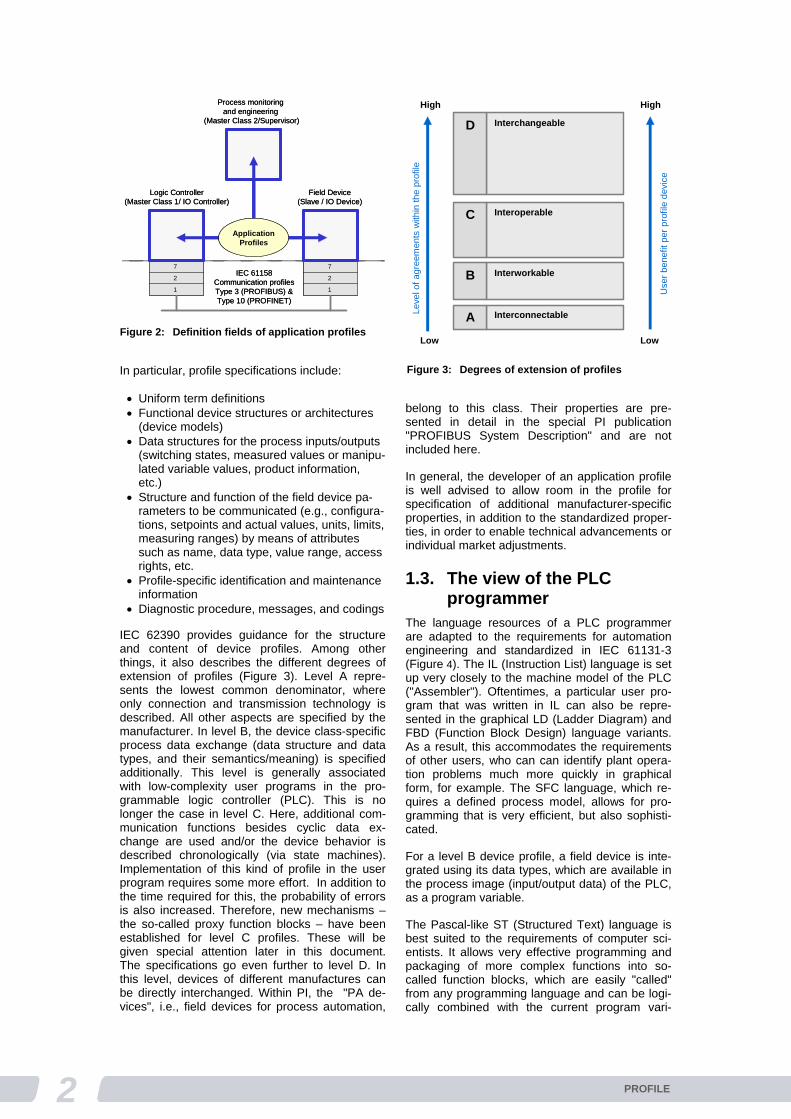
Diagnostic procedure, messages, and codings IEC 62390 provides guidance for the structure and content of device profiles. Among other things, it also describes the different degrees of extension of profiles (Figure 3). Level A repre-sents the lowest common denominator, where only connection and transmission technology is described. All other aspects are specified by the manufacturer. In level B, the device class-specific process data exchange (data structure and data types, and their semantics/meaning) is specified additionally. This level is generally associated with low-complexity user programs in the pro-grammable logic controller (PLC). This is no longer the case in level C. Here, additional com-munication functions besides cyclic data ex-change are used and/or the device behavior is described chronologically (via state machines). Implementation of this kind of profile in the user program requires some more effort. In addition to the time required for this, the probability of errors is also increased. Therefore, new mechanisms – the so-called proxy function blocks – have been established for level C profiles. These will be given special attention later in this document. The specifications go even further to level D. In this level, devices of different manufactures can be directly interchanged. Within PI, the "PA de-vices", i.e., field devices for process automation,
belong to this class. Their properties are pre-sented in detail in the special PI publication "PROFIBUS System Description" and are not included here.
In general, the developer of an application profile is well advised to allow room in the profile for specification of additional manufacturer-specific properties, in addition to the standardized proper-ties, in order to enable technical advancements or individual market adjustments.
1.3. The view of the PLC programmer
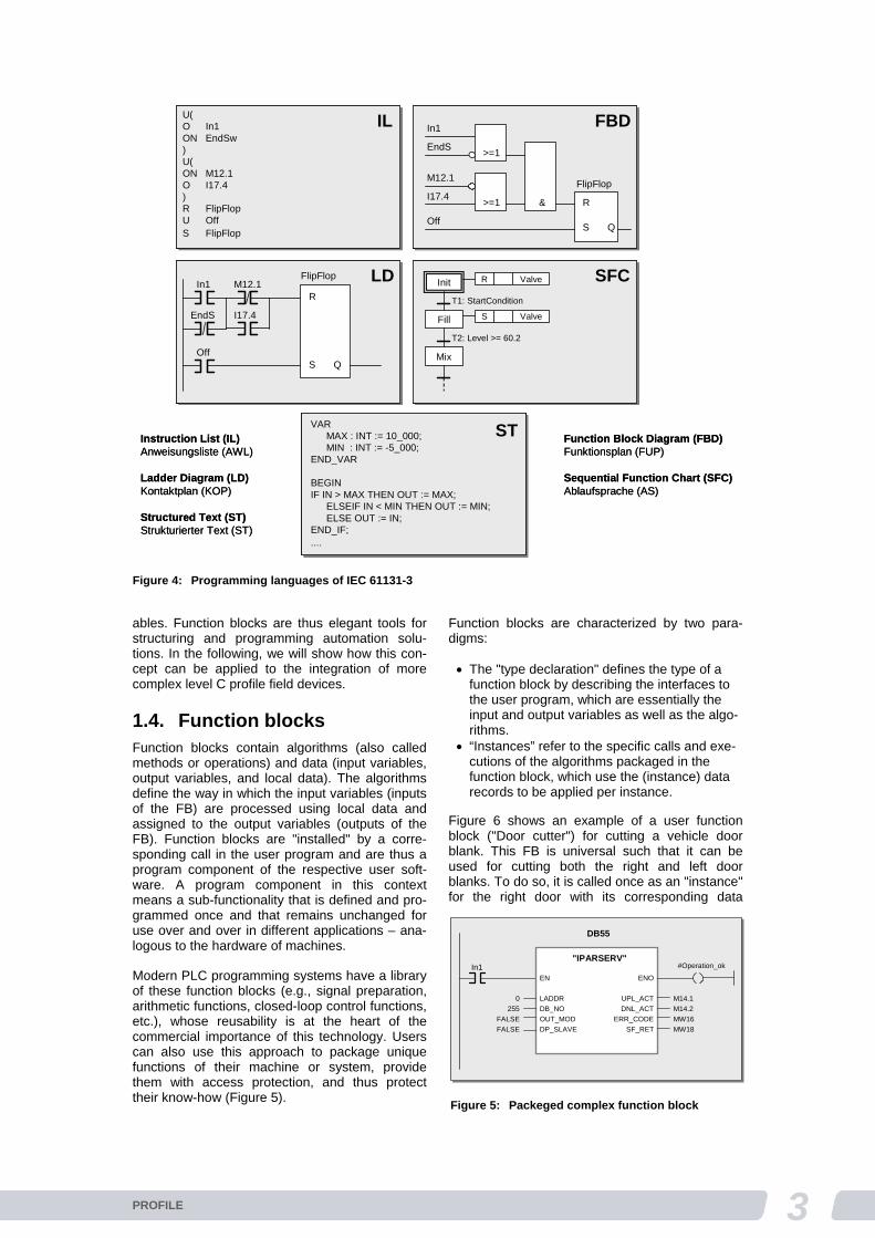
The language resources of a PLC programmer are adapted to the requirements for automation engineering and standardized in IEC 61131-3 (Figure 4). The IL (Instruction List) language is set up very closely to the machine model of the PLC ("Assembler"). Oftentimes, a particular user pro-gram that was written in IL can also be repre-sented in the graphical LD (Ladder Diagram) and FBD (Function Block Design) language variants. As a result, this accommodates the requirements of other users, who can can identify plant opera-tion problems much more quickly in graphical form, for example. The SFC language, which re-quires a defined process model, allows for pro-gramming that is very efficient, but also sophisti-cated.
For a level B device profile, a field device is inte-grated using its data types, which are available in the process image (input/output data) of the PLC, as a program variable.
The Pascal-like ST (Structured Text) language is best suited to the requirements of computer sci-entists. It allows very effective programming and packaging of more complex functions into so-called function blocks, which are easily "called" from any programming language and can be logi-cally combined with the current program vari-
1
2
7
1
2
7
Logic Controller (Master Class 1/ IO Controller)
Field Device(Slave / IO Device)
Process monitoringand engineering
(Master Class 2/Supervisor)
IEC 61158Communication profilesType 3 (PROFIBUS) &Type 10 (PROFINET)
ApplicationProfiles
1
2
7
1
2
7
Logic Controller (Master Class 1/ IO Controller)
Field Device(Slave / IO Device)
Process monitoringand engineering
(Master Class 2/Supervisor)
IEC 61158Communication profilesType 3 (PROFIBUS) &Type 10 (PROFINET)
ApplicationProfiles
Figure 2: Definition fields of application profiles
Interconnectable
Interworkable
Interoperable
Interchangeable
Leve
l of
agre
emen
tsw
ithin
the
prof
ile
Use
r be
nefit
per
prof
ilede
vice
High
Low
High
Low
A
B
C
D
Figure 3: Degrees of extension of profiles
3PROFILE
ables. Function blocks are thus elegant tools for structuring and programming automation solu-tions. In the following, we will show how this con-cept can be applied to the integration of more complex level C profile field devices.
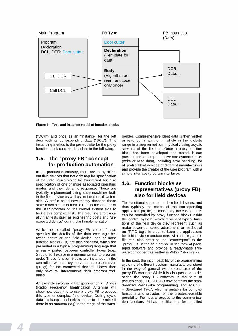
1.4. Function blocks Function blocks contain algorithms (also called methods or operations) and data (input variables, output variables, and local data). The algorithms define the way in which the input variables (inputs of the FB) are processed using local data and assigned to the output variables (outputs of the FB). Function blocks are "installed" by a corre-sponding call in the user program and are thus a program component of the respective user soft-ware. A program component in this context means a sub-functionality that is defined and pro-grammed once and that remains unchanged for use over and over in different applications – ana-logous to the hardware of machines.
Modern PLC programming systems have a library of these function blocks (e.g., signal preparation, arithmetic functions, closed-loop control functions, etc.), whose reusability is at the heart of the commercial importance of this technology. Users can also use this approach to package unique functions of their machine or system, provide them with access protection, and thus protect their know-how (Figure 5).
Function blocks are characterized by two para-digms:
The "type declaration" defines the type of a function block by describing the interfaces to the user program, which are essentially the input and output variables as well as the algo-rithms.
“Instances” refer to the specific calls and exe-cutions of the algorithms packaged in the function block, which use the (instance) data records to be applied per instance.
Figure 6 shows an example of a user function block ("Door cutter") for cutting a vehicle door blank. This FB is universal such that it can be used for cutting both the right and left door blanks. To do so, it is called once as an "instance" for the right door with its corresponding data
U(O In1ON EndSw)U(ON M12.1O I17.4)R FlipFlopU OffS FlipFlop
FlipFlop
R
S QOff
In1
EndS
M12.1
I17.4&>=1
>=1
Init
Fill
Mix
R Valve
S Valve
T1: StartCondition
T2: Level >= 60.2
FlipFlop
R
S Q
In1 M12.1
EndS I17.4
Off
VARMAX : INT := 10_000;MIN : INT := -5_000;
END_VAR
BEGINIF IN > MAX THEN OUT := MAX;
ELSEIF IN < MIN THEN OUT := MIN;ELSE OUT := IN;
END_IF;....
Instruction List (IL)Anweisungsliste (AWL)
Ladder Diagram (LD)Kontaktplan (KOP)
Structured Text (ST)Strukturierter Text (ST)
IL FBD
LD SFC
ST Function Block Diagram (FBD)Funktionsplan (FUP)
Sequential Function Chart (SFC)Ablaufsprache (AS)
U(O In1ON EndSw)U(ON M12.1O I17.4)R FlipFlopU OffS FlipFlop
FlipFlop
R
S QOff
In1
EndS
M12.1
I17.4&>=1
>=1
FlipFlop
R
S QOff
In1
EndS
M12.1
I17.4&>=1
>=1
Init
Fill
Mix
R Valve
S Valve
T1: StartCondition
T2: Level >= 60.2
Init
Fill
Mix
R Valve
S Valve
T1: StartCondition
T2: Level >= 60.2
FlipFlop
R
S Q
In1 M12.1
EndS I17.4
Off
FlipFlop
R
S Q
In1 M12.1
EndS I17.4
Off
VARMAX : INT := 10_000;MIN : INT := -5_000;
END_VAR
BEGINIF IN > MAX THEN OUT := MAX;
ELSEIF IN < MIN THEN OUT := MIN;ELSE OUT := IN;
END_IF;....
VARMAX : INT := 10_000;MIN : INT := -5_000;
END_VAR
BEGINIF IN > MAX THEN OUT := MAX;
ELSEIF IN < MIN THEN OUT := MIN;ELSE OUT := IN;
END_IF;....
Instruction List (IL)Anweisungsliste (AWL)
Ladder Diagram (LD)Kontaktplan (KOP)
Structured Text (ST)Strukturierter Text (ST)
IL FBD
LD SFC
ST Function Block Diagram (FBD)Funktionsplan (FUP)
Sequential Function Chart (SFC)Ablaufsprache (AS)
Figure 4: Programming languages of IEC 61131-3
In1"IPARSERV"
EN
LADDR
DB_NO
OUT_MOD
DP_SLAVE
0
255
FALSE
FALSE
ENO
UPL_ACT
DNL_ACT
ERR_CODE
SF_RET
M14.1
M14.2
MW16
MW18
DB55
#Operation_ok
Figure 5: Packeged complex function block
4 PROFILE
("DCR") and once as an "instance" for the left door with its corresponding data ("DCL"). This instancing method is the prerequisite for the proxy function block concept described in the following.
1.5. The “proxy FB” concept for production automation
In the production industry, there are many differ-ent field devices that not only require specification of the data structures to be transferred but also specification of one or more associated operating modes and their dynamic response. These are typically implemented using state machines both in the field device as well as on the control system side. A profile could now merely describe these state machines. It is then left up to the creator of the user program on the control system side to tackle this complex task. The resulting effort usu-ally manifests itself as engineering costs and "un-expected delays" during plant implementation.
While the so-called "proxy FB concept" also specifies the details of the data exchange be-tween controller and field device, one or more function blocks (FB) are also specified, which are presented in a typical programming language that is easily ported between controller types (e.g., Structured Text) or in a manner similar to program code. These function blocks are instanced in the controller, where they serve as representatives (proxy) for the connected devices. Users then only have to "interconnect" their program vari-ables.
An example involving a transponder for RFID tags (Radio Frequency Identification Antenna) will show how easy it is to use a proxy FB to access this type of complex field device. During cyclic data exchange, a check is made to determine if there is an antenna (tag) in the range of the trans-
ponder. Comprehensive Ident data is then written or read out in part or in whole in the kilobyte range in a segmented form, typically using acyclic services of the fieldbus. Once a proxy function block has been developed and tested, it can package these comprehensive and dynamic tasks (write or read data), including error handling, for all profile Ident devices of different manufacturers and provide the creator of the user program with a simple interface (program interface).
1.6. Function blocks as representatives (proxy FB) also for field devices
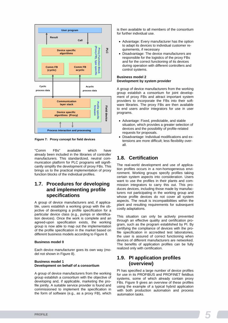
The functional scope of modern field devices, and thus typically the scope of the corresponding application profile, is constantly increasing. This can be remedied by proxy function blocks inside the control system, which represent typical func-tions of the field device they represent, such as motor power-up, speed adjustment, or readout of an "RFID tag". In order to keep the applications for field device manufacturers within limits, a pro-file can also describe the "counterpart" to the "proxy FB" in the field device in the form of pack-aged software and provide a ready-made firm-ware component as written in ANSI-C (Figure 7).
In the past, the incompatibility of the programming systems of different system manufacturers stood in the way of general wide-spread use of the proxy FB concept. While it is also possible to de-scribe the proxy FB software in the form of pseudo code, IEC 61131-3 now contains the stan-dardized Pascal-like programming language "ST = Structured Text", which is suitable for complex functions and provides for the greatest-possible portability. For neutral access to the communica-tion functions, PI has specifications for so-called
ProgramDeclaration:DCL, DCR: Door cutter;
Door cutter
Declaration(Template fordata)
Body(Algorithm asreentrant codeonly once)
FB TypeMain Program
Call DCR
Call DCL
DCRData....
DCLData....
FB Instances(Data)
Figure 6: Type and instance model of function blocks
5PROFILE
with both production automation and process automation tasks.
"Comm FBs" available which have already been included in the libraries of controller manufacturers. This standardized, neutral com-munication platform for PLC programs will signifi-cantly simplify the development of proxy FBs. This brings us to the practical implementation of proxy function blocks of the individual profiles.
1.7. Procedures for developing and implementing profile specifications
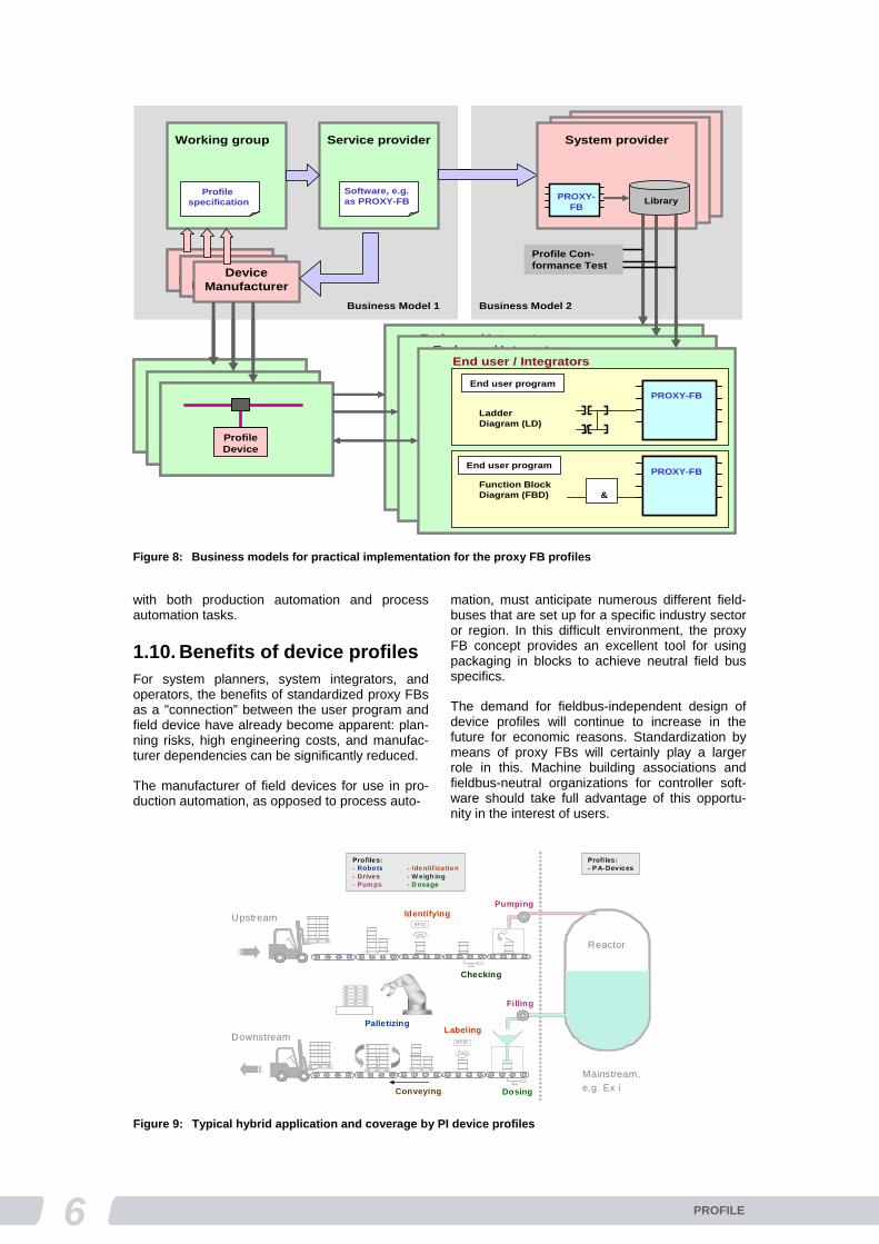
A group of device manufacturers and, if applica-ble, users establish a working group with the ob-jective of developing a profile specification for a particular device class (e.g., pumps or identifica-tion devices). Once the work is complete and an agreed-upon specification exists, the working group is now able to map out the implementation of the profile specification in the market based on different business models according to Figure 8.
Business model 0
Each device manufacturer goes its own way (mo-del not shown in Figure 8).
Business model 1 Development on behalf of a consortium
A group of device manufacturers from the working group establish a consortium with the objective of developing and, if applicable, marketing the pro-file jointly. A suitable service provider is found and commissioned to implement the specification in the form of software (e.g., as a proxy FB), which
is then available to all members of the consortium for further individual use.
Advantage: Every manufacturer has the option to adapt its devices to individual customer re-quirements, if necessary
Disadvantage: The device manufacturers are responsible for the logistics of the proxy FBs and for the correct functioning of its devices during operation with different controllers and control systems.
Business model 2 Development by system provider
A group of device manufacturers from the working group establish a consortium for joint develop-ment of proxy FBs and attract important system providers to incorporate the FBs into their soft-ware libraries. The proxy FBs are then available to end users and/or integrators for use in user programs.
Advantage: Fixed, predictable, and stable situation, which provides a greater selection of devices and the possibility of profile-related requests for proposals.
Disadvantage: Individual modifications and ex-tensions are more difficult; less flexibility over-all.
1.8. Certification The real-world development and use of applica-tion profiles occurs in a non-homogeneous envi-ronment. Working groups specify profiles taking certain system aspects into consideration. Users want to use the profiles in their plants and com-mission integrators to carry this out. This pro-duces devices, including those made by manufac-turers not participating in the working group and whose profile devices do not cover all system aspects. The result is incompatibilities within the plant and resulting requirements for subsequent costly adaptations.
This situation can only be actively prevented through an effective quality and certification pro-gram, such as the program established by PI. By certifying the compliance of devices with the pro-file specification in accredited test laboratories, the user is assured of correct functioning when devices of different manufacturers are networked. The benefits of application profiles can be fully realized only with certification.
1.9. PI application profiles (overview)
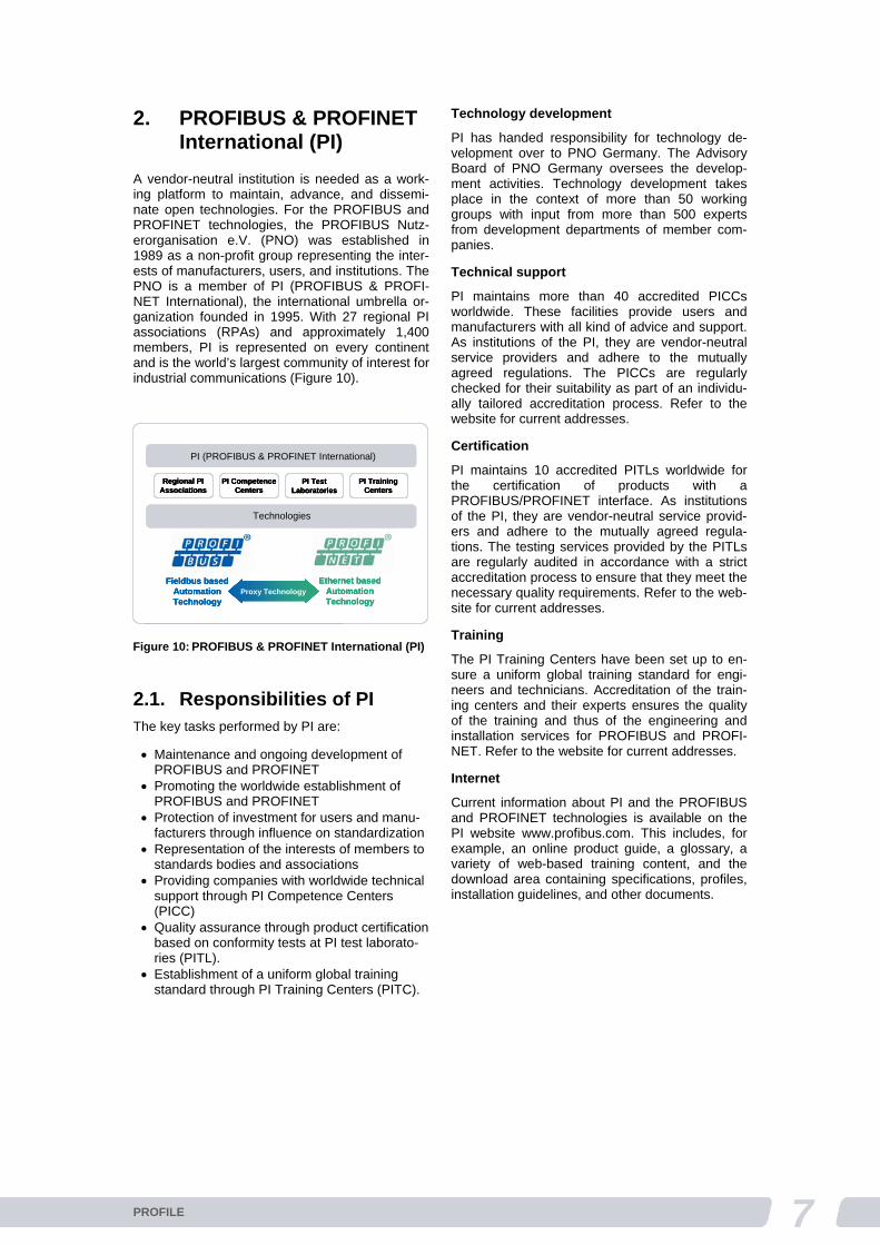
PI has specified a large number of device profiles for use in its PROFIBUS and PROFINET fieldbus systems, some of which already contain proxy FBs. Figure 9 gives an overview of these profiles using the example of a typical hybrid application
Comm FB (cyclic)
Comm FB acyclic
Device specificalgorithms
Cyclic
process data
Pro
xy F
un
ctio
nB
loc
k
(Pro
xy-F
B), typ
es
pe
cific
User program
CallResult
PL
CF
ield
dev
ice
Process interaction and processing
Acyclic
process data
Communicationlayer stack
Device specificalgorithms (Proxy)
Pro
file s
pe
cific
firmw
are
Figure 7: Proxy concept for field devices
6 PROFILE
with both production automation and process automation tasks.
1.10. Benefits of device profiles For system planners, system integrators, and operators, the benefits of standardized proxy FBs as a "connection” between the user program and field device have already become apparent: plan-ning risks, high engineering costs, and manufac-turer dependencies can be significantly reduced.
The manufacturer of field devices for use in pro-duction automation, as opposed to process auto-
mation, must anticipate numerous different field-buses that are set up for a specific industry sector or region. In this difficult environment, the proxy FB concept provides an excellent tool for using packaging in blocks to achieve neutral field bus specifics.
The demand for fieldbus-independent design of device profiles will continue to increase in the future for economic reasons. Standardization by means of proxy FBs will certainly play a larger role in this. Machine building associations and fieldbus-neutral organizations for controller soft-ware should take full advantage of this opportu-nity in the interest of users.
Working group
Profile specification
Service provider
Software, e.g. as PROXY-FB
System provider
PROXY-FB
PROXY-FB
Ladder Diagram (LD)
PROXY-FB
Function Block Diagram (FBD) &
End user / Integrators
End user program
End user program
PROXY-FB
Ladder Diagram (LD)
PROXY-FB
Function Block Diagram (FBD) &
End user / Integrators
End user program
End user program
PROXY-FB
Ladder Diagram (LD)
PROXY-FB
Function Block Diagram (FBD) &
End user / Integrators
End user program
End user program
DeviceManufacturer
DeviceManufacturer
DeviceManufacturer
Business Model 2Business Model 1
Library
Profile Con-formance Test
Profile Device Profile
Device Profile Device
Working group
Profile specification
Service provider
Software, e.g. as PROXY-FB
System provider
PROXY-FB
PROXY-FBPROXY-FB
Ladder Diagram (LD)
PROXY-FBPROXY-FB
Function Block Diagram (FBD) &
End user / Integrators
End user program
End user program
PROXY-FBPROXY-FB
Ladder Diagram (LD)
PROXY-FBPROXY-FB
Function Block Diagram (FBD) &
End user / Integrators
End user program
End user program
PROXY-FBPROXY-FB
Ladder Diagram (LD)
PROXY-FBPROXY-FB
Function Block Diagram (FBD) &
End user / Integrators
End user program
End user program
DeviceManufacturer
DeviceManufacturer
DeviceManufacturer
DeviceManufacturer
DeviceManufacturer
Business Model 2Business Model 1
Library
Profile Con-formance Test
Profile Device Profile Device Profile Device Profile Device Profile
Device Profile Device Profile Device Profile Device Profile
Device Profile Device Profile Device Profile Device
Figure 8: Business models for practical implementation for the proxy FB profiles
RFID
RFID
Upstream
Downstream
Mainstream,
e.g. Ex i
Reactor
Profiles:- Robots - Identif ication- Drives - W eigh ing- Pumps - D osage
Profiles:- P A-Devices
Conveying
Identifying
Checking
Pumping
Labeling
Filling
Dosing
Palletizing
Figure 9: Typical hybrid application and coverage by PI device profiles
7PROFILE
2. PROFIBUS & PROFINET International (PI)
A vendor-neutral institution is needed as a work-ing platform to maintain, advance, and dissemi-nate open technologies. For the PROFIBUS and PROFINET technologies, the PROFIBUS Nutz-erorganisation e.V. (PNO) was established in 1989 as a non-profit group representing the inter-ests of manufacturers, users, and institutions. The PNO is a member of PI (PROFIBUS & PROFI-NET International), the international umbrella or-ganization founded in 1995. With 27 regional PI associations (RPAs) and approximately 1,400 members, PI is represented on every continent and is the world’s largest community of interest for industrial communications (Figure 10).
2.1. Responsibilities of PI The key tasks performed by PI are:
Maintenance and ongoing development of PROFIBUS and PROFINET
Promoting the worldwide establishment of PROFIBUS and PROFINET
Protection of investment for users and manu-facturers through influence on standardization
Representation of the interests of members to standards bodies and associations
Providing companies with worldwide technical support through PI Competence Centers (PICC)
Quality assurance through product certification based on conformity tests at PI test laborato-ries (PITL).
Establishment of a uniform global training standard through PI Training Centers (PITC).
Technology development
PI has handed responsibility for technology de-velopment over to PNO Germany. The Advisory Board of PNO Germany oversees the develop-ment activities. Technology development takes place in the context of more than 50 working groups with input from more than 500 experts from development departments of member com-panies.
Technical support
PI maintains more than 40 accredited PICCs worldwide. These facilities provide users and manufacturers with all kind of advice and support. As institutions of the PI, they are vendor-neutral service providers and adhere to the mutually agreed regulations. The PICCs are regularly checked for their suitability as part of an individu-ally tailored accreditation process. Refer to the website for current addresses.
Certification
PI maintains 10 accredited PITLs worldwide for the certification of products with a PROFIBUS/PROFINET interface. As institutions of the PI, they are vendor-neutral service provid-ers and adhere to the mutually agreed regula-tions. The testing services provided by the PITLs are regularly audited in accordance with a strict accreditation process to ensure that they meet the necessary quality requirements. Refer to the web-site for current addresses.
Training
The PI Training Centers have been set up to en-sure a uniform global training standard for engi-neers and technicians. Accreditation of the train-ing centers and their experts ensures the quality of the training and thus of the engineering and installation services for PROFIBUS and PROFI-NET. Refer to the website for current addresses.
Internet
Current information about PI and the PROFIBUS and PROFINET technologies is available on the PI website www.profibus.com. This includes, for example, an online product guide, a glossary, a variety of web-based training content, and the download area containing specifications, profiles, installation guidelines, and other documents.
Regional PI Associations
PI Competence Centers
PI Test Laboratories
PI Training Centers
PI (PROFIBUS & PROFINET International)
Technologies
Fieldbus based Automation Technology
Ethernet based Automation Technology
Proxy Technology
Regional PI Associations
PI Competence Centers
PI Test Laboratories
PI Training Centers
PI (PROFIBUS & PROFINET International)
Technologies
Fieldbus based Automation Technology
Ethernet based Automation Technology
Proxy Technology
Regional PI Associations
PI Competence Centers
PI Test Laboratories
PI Training Centers
PI (PROFIBUS & PROFINET International)
Technologies
Fieldbus based Automation Technology
Ethernet based Automation Technology
Proxy Technology
Figure 10: PROFIBUS & PROFINET International (PI)
PROFILE System Description – Technology and Application
Version November 2010
Order number 4.352
Publisher
PROFIBUS Nutzerorganisation e.V. PNO Haid und Neu-Str. 7 76313 Karlsruhe Germany Tel.: +49 (0)721 / 96 58 590 Fax: +49 (0)721 / 96 58 589 [email protected]
Exclusion of liability
PROFIBUS Nutzerorganisation has examined the contents of this brochure carefully. Nevertheless, errors can not be excluded. Liability of PROFIBUS Nutzerorganisation is excluded, regardless of the reason. The data in this brochure is checked periodically, however. Necessary corrections will be con-tained in subsequent versions. We gratefully accept suggestions for improvement.
Terms used in this brochure may be trade marks and their use by third parties for any purposes may violate the rights of the owner.
This brochure is not a substitute for the respective IEC standards, e.g. IEC 61158 and IEC 61784, and the associated specifications and guidelines of PROFIBUS & PROFINET International. In case of doubt, these documents take precendence.
© Copyright by PROFIBUS Nutzerorganisation e.V. 2010. All rights reserved.
PROFIBUS Nutzerorganisation e. V. (PNO)Member of PROFIBUS & PROFINET InternationalHaid-und-Neu-Str. 7 • 76131 Karlsruhe • GermanyPhone +49 721 96 58 590 • Fax +49 721 96 58 589www.profibus.com • www.profinet.com
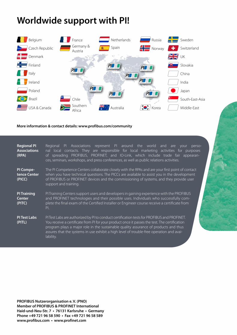
Worldwide support with PI!
Regional PI Associations (RPA)
PI Compe-tence Center (PICC)
PI Training Center (PITC)
PI Test Labs (PITL)
Regional PI Associations represent PI around the world and are your perso-nal local contacts. They are responsible for local marketing activities for purposes of spreading PROFIBUS, PROFINET, and IO-Link, which include trade fair appearan-ces, seminars, workshops, and press conferences, as well as public relations activities.
The PI Competence Centers collaborate closely with the RPAs and are your first point of contact when you have technical questions. The PICCs are available to assist you in the development of PROFIBUS or PROFINET devices and the commissioning of systems, and they provide user support and training.
PI Training Centers support users and developers in gaining experience with the PROFIBUS and PROFINET technologies and their possible uses. Individuals who successfully com-plete the final exam of the Certified Installer or Engineer course receive a certificate from PI.
PI Test Labs are authorized by PI to conduct certification tests for PROFIBUS and PROFINET. You receive a certificate from PI for your product once it passes the test. The certification program plays a major role in the sustainable quality assurance of products and thus assures that the systems in use exhibit a high level of trouble-free operation and avai-lability.
More information & contact details: www.profibus.com/community
Belgium France Netherlands Russia Sweden
Czech Republic Germany & Austria
Norway
Slovakia
Switzerland
Denmark
Ireland
Spain
UK
Finland
Italy China
India
Japan
Korea Middle-East
South-East-Asia
AustraliaSouthernAfrica
USA & Canada
ChileBrazil
Poland