Embed Size (px)
Citation preview

N e v e r s t o p t h i n k i n g .
Automot ive Power
Tool Descr ipt ion, V 2.0, Apr i l 2004
PROFET Demo KitBTS 5241LBTS 5234GBTS 5230GSBTS 6143D
PROFET Demo Kit Revision History: 2004-04-02 V 2.0
Previous Version: 2003-03 V 1.0
V 1.0 Supported Devices:• BTS 5240L• BTS 5440G• BTS 6143D
V 2.0 Supported Devices:• BTS 5241L• BTS 5234G• BTS 5230GS• BTS 6143D
N e v e r s t o p t h i n k i n g .
Automot ive Power
Tool Descr ipt ion, V 2.0, Apr i l 2004
PROFET Demo KitBTS 5241LBTS 5234GBTS 5230GSBTS 6143D
Tool DescriptionPROFET Demo Kit
Table of Contents Page
Tool Description 4 V 2.0, 2004-04-02
1 Hardware Description . . . . . . . . . . . . . . . . . . . . . . . . . . . . . . . . . . . . . . . . 51.1 P-DSO-12 Board . . . . . . . . . . . . . . . . . . . . . . . . . . . . . . . . . . . . . . . . . . . . . 51.1.1 Technical Data of BTS 5241L . . . . . . . . . . . . . . . . . . . . . . . . . . . . . . . . . 51.1.2 Connectors and Plugs . . . . . . . . . . . . . . . . . . . . . . . . . . . . . . . . . . . . . . . 61.1.3 Circuit Diagram . . . . . . . . . . . . . . . . . . . . . . . . . . . . . . . . . . . . . . . . . . . . 71.2 P-DSO-20 Board . . . . . . . . . . . . . . . . . . . . . . . . . . . . . . . . . . . . . . . . . . . . . 81.2.1 Technical Data of BTS 5234G . . . . . . . . . . . . . . . . . . . . . . . . . . . . . . . . . 81.2.2 Connectors and Plugs . . . . . . . . . . . . . . . . . . . . . . . . . . . . . . . . . . . . . . . 91.2.3 Circuit Diagram . . . . . . . . . . . . . . . . . . . . . . . . . . . . . . . . . . . . . . . . . . . 101.3 P-DSO-14 Board . . . . . . . . . . . . . . . . . . . . . . . . . . . . . . . . . . . . . . . . . . . . 111.3.1 Technical Data of BTS 5230GS . . . . . . . . . . . . . . . . . . . . . . . . . . . . . . . 111.3.2 Connectors and Plugs . . . . . . . . . . . . . . . . . . . . . . . . . . . . . . . . . . . . . . 121.3.3 Circuit Diagram . . . . . . . . . . . . . . . . . . . . . . . . . . . . . . . . . . . . . . . . . . . 131.4 Power HIC Board . . . . . . . . . . . . . . . . . . . . . . . . . . . . . . . . . . . . . . . . . . . . 141.4.1 Technical Data of BTS 6143D . . . . . . . . . . . . . . . . . . . . . . . . . . . . . . . . 141.4.2 Connectors and Plugs . . . . . . . . . . . . . . . . . . . . . . . . . . . . . . . . . . . . . . 151.4.3 Circuit Diagram . . . . . . . . . . . . . . . . . . . . . . . . . . . . . . . . . . . . . . . . . . . 161.5 Control Board . . . . . . . . . . . . . . . . . . . . . . . . . . . . . . . . . . . . . . . . . . . . . . . 171.5.1 Technical Data of Control Board . . . . . . . . . . . . . . . . . . . . . . . . . . . . . . 171.5.2 Connectors and Plugs . . . . . . . . . . . . . . . . . . . . . . . . . . . . . . . . . . . . . . 181.5.3 Circuit Diagram . . . . . . . . . . . . . . . . . . . . . . . . . . . . . . . . . . . . . . . . . . . 19
2 Software Description . . . . . . . . . . . . . . . . . . . . . . . . . . . . . . . . . . . . . . . . 202.1 Main Function . . . . . . . . . . . . . . . . . . . . . . . . . . . . . . . . . . . . . . . . . . . . . . 202.2 Details on Firmware Modules . . . . . . . . . . . . . . . . . . . . . . . . . . . . . . . . . . 202.2.1 Diagnosis . . . . . . . . . . . . . . . . . . . . . . . . . . . . . . . . . . . . . . . . . . . . . . . . 202.2.2 Low Load: Blink Double Speed . . . . . . . . . . . . . . . . . . . . . . . . . . . . . . . 202.2.3 Vbb Dependent PWM . . . . . . . . . . . . . . . . . . . . . . . . . . . . . . . . . . . . . . . 21
3 Download Software . . . . . . . . . . . . . . . . . . . . . . . . . . . . . . . . . . . . . . . . . 223.1 Download Procedure . . . . . . . . . . . . . . . . . . . . . . . . . . . . . . . . . . . . . . . . . 223.2 Using DTR Line as Reset Signal . . . . . . . . . . . . . . . . . . . . . . . . . . . . . . . . 233.3 Setup Dialog . . . . . . . . . . . . . . . . . . . . . . . . . . . . . . . . . . . . . . . . . . . . . . . 23
A Appendix . . . . . . . . . . . . . . . . . . . . . . . . . . . . . . . . . . . . . . . . . . . . . . . . . 25A.1 Board Layout P-DSO-12 Board . . . . . . . . . . . . . . . . . . . . . . . . . . . . . . . . . 25A.2 Board Layout P-DSO-20 Board . . . . . . . . . . . . . . . . . . . . . . . . . . . . . . . . . 26A.3 Board Layout P-DSO-14 Board . . . . . . . . . . . . . . . . . . . . . . . . . . . . . . . . . 27A.4 Board Layout Power HIC Board . . . . . . . . . . . . . . . . . . . . . . . . . . . . . . . . 28A.5 Board Layout Control Board . . . . . . . . . . . . . . . . . . . . . . . . . . . . . . . . . . . 29

Tool DescriptionPROFET Demo Kit
Hardware Description
1 Hardware Description
1.1 P-DSO-12 Board
The P-DSO-12 Board is equipped with one BTS 5241L in P-DSO-12 power package. Itis capable to drive two 55 W channels for blinker applications which might be built by25 W + 25 W + 5 W bulbs. These combination of loads can be found in the car as front,rear and side blinker.
Figure 1 P-DSO-12 Board
1.1.1 Technical Data of BTS 5241L
Operating Voltage Vbb(ON) 4.5 V .. 28 V
On-state Resistance RON 25 mΩ per channel
Nominal load current1)
continuousblinking (50% duty cycle)
1) Power dissipation Ptot = 1 W
IL(nom) (all channels active)3.3 A per channel4.5 A per channel
Current limitation IL(lim)IL(SCr)
40 A
9.5 A
Package P-DSO-12 (power)
BTS5241L
OUT1 OUT2
VBBOUT1
VBB
ROL
OUT2
ROL
IN1 IN2
IS1 IS2
SEN GND
GN
D
RIS RIS
Tool Description 5 V 2.0, 2004-04-02
Tool DescriptionPROFET Demo Kit
Hardware Description
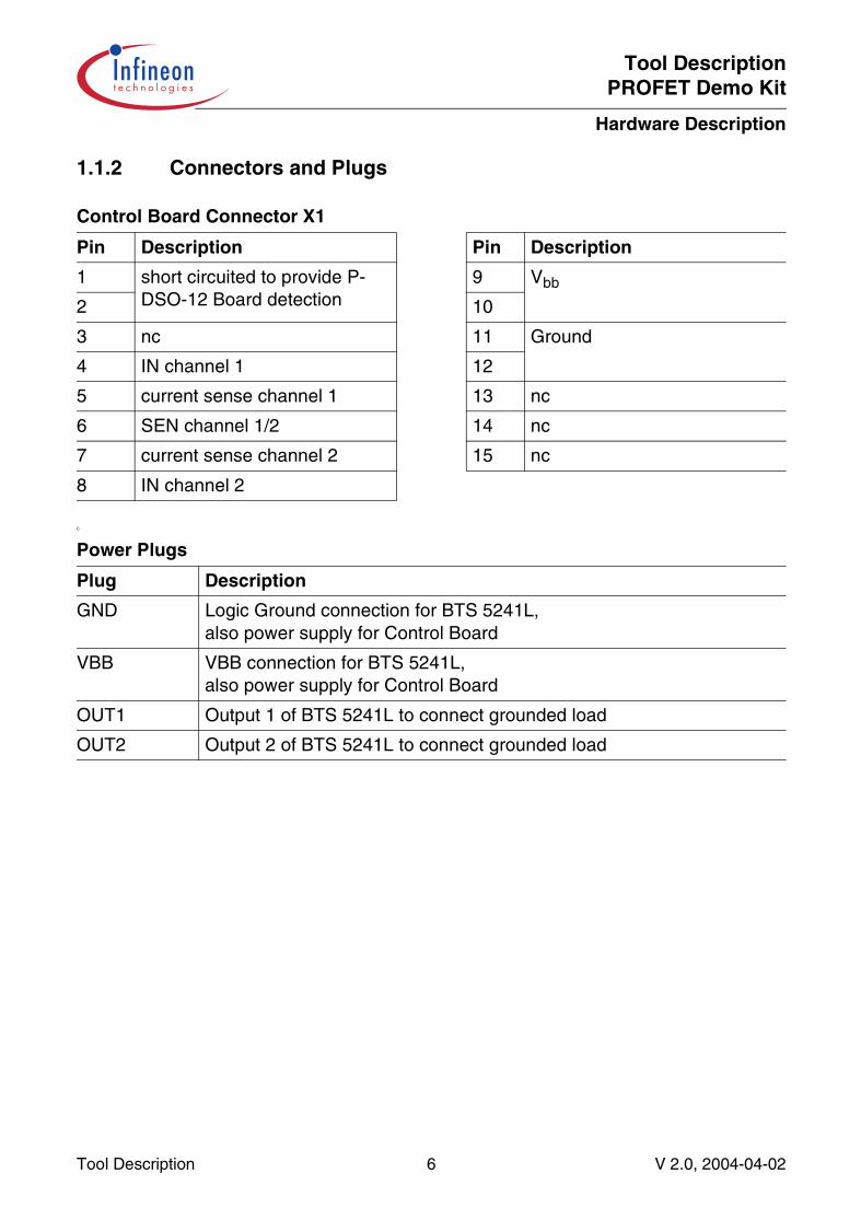
1.1.2 Connectors and Plugs
C
Control Board Connector X1
Pin Description Pin Description
1 short circuited to provide P-DSO-12 Board detection
9 Vbb
2 10
3 nc 11 Ground
4 IN channel 1 12
5 current sense channel 1 13 nc
6 SEN channel 1/2 14 nc
7 current sense channel 2 15 nc
8 IN channel 2
Power Plugs
Plug Description
GND Logic Ground connection for BTS 5241L,also power supply for Control Board
VBB VBB connection for BTS 5241L,also power supply for Control Board
OUT1 Output 1 of BTS 5241L to connect grounded load
OUT2 Output 2 of BTS 5241L to connect grounded load
Tool Description 6 V 2.0, 2004-04-02
Tool DescriptionPROFET Demo Kit
Hardware Description
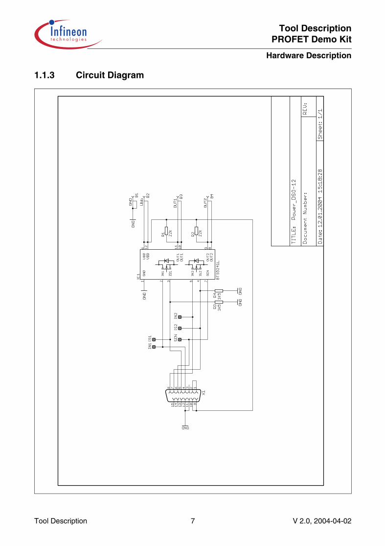
1.1.3 Circuit Diagram
Tool Description 7 V 2.0, 2004-04-02
Tool DescriptionPROFET Demo Kit
Hardware Description
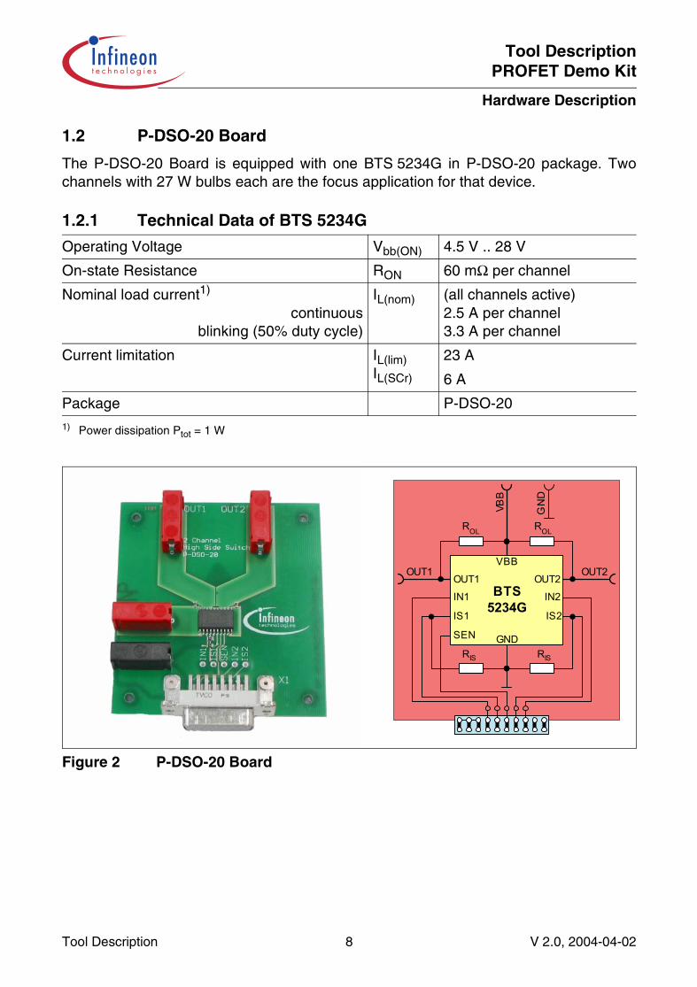
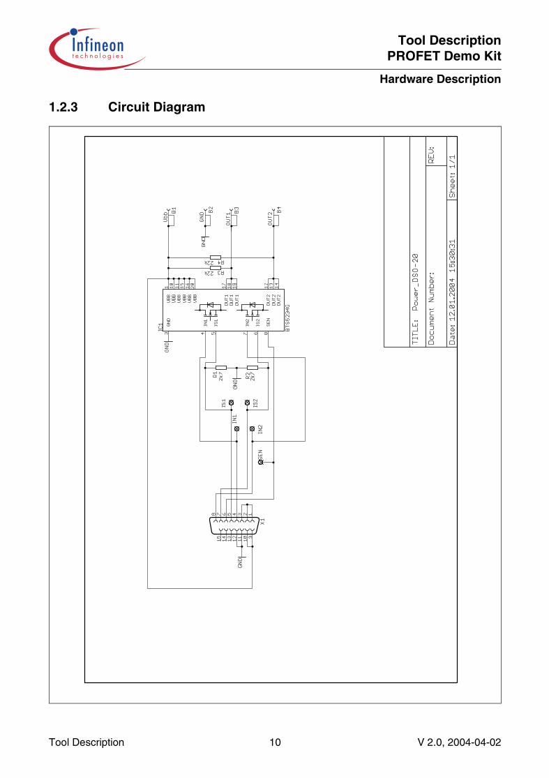
1.2 P-DSO-20 Board
The P-DSO-20 Board is equipped with one BTS 5234G in P-DSO-20 package. Twochannels with 27 W bulbs each are the focus application for that device.
Figure 2 P-DSO-20 Board
1.2.1 Technical Data of BTS 5234G
Operating Voltage Vbb(ON) 4.5 V .. 28 V
On-state Resistance RON 60 mΩ per channel
Nominal load current1)
continuousblinking (50% duty cycle)
1) Power dissipation Ptot = 1 W
IL(nom) (all channels active)2.5 A per channel3.3 A per channel
Current limitation IL(lim)IL(SCr)
23 A
6 A
Package P-DSO-20
BTS5234G
OUT1 OUT2
VBBOUT1
VBB
ROL
OUT2
ROL
IN1 IN2
IS1 IS2
SEN GND
GN
D
RIS RIS
Tool Description 8 V 2.0, 2004-04-02
Tool DescriptionPROFET Demo Kit
Hardware Description
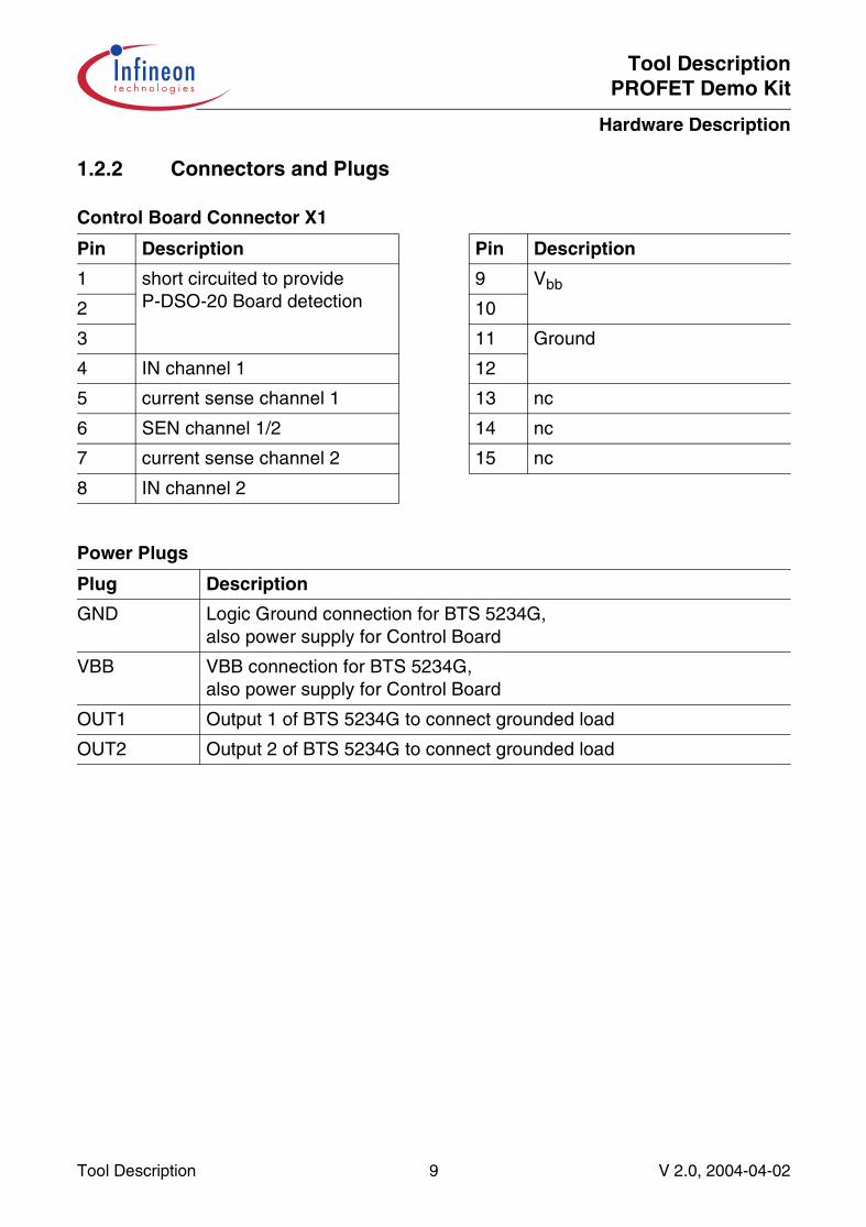
1.2.2 Connectors and Plugs
Control Board Connector X1
Pin Description Pin Description
1 short circuited to provide P-DSO-20 Board detection
9 Vbb
2 10
3 11 Ground
4 IN channel 1 12
5 current sense channel 1 13 nc
6 SEN channel 1/2 14 nc
7 current sense channel 2 15 nc
8 IN channel 2
Power Plugs
Plug Description
GND Logic Ground connection for BTS 5234G,also power supply for Control Board
VBB VBB connection for BTS 5234G,also power supply for Control Board
OUT1 Output 1 of BTS 5234G to connect grounded load
OUT2 Output 2 of BTS 5234G to connect grounded load
Tool Description 9 V 2.0, 2004-04-02
Tool DescriptionPROFET Demo Kit
Hardware Description
1.2.3 Circuit Diagram
Tool Description 10 V 2.0, 2004-04-02
Tool DescriptionPROFET Demo Kit
Hardware Description
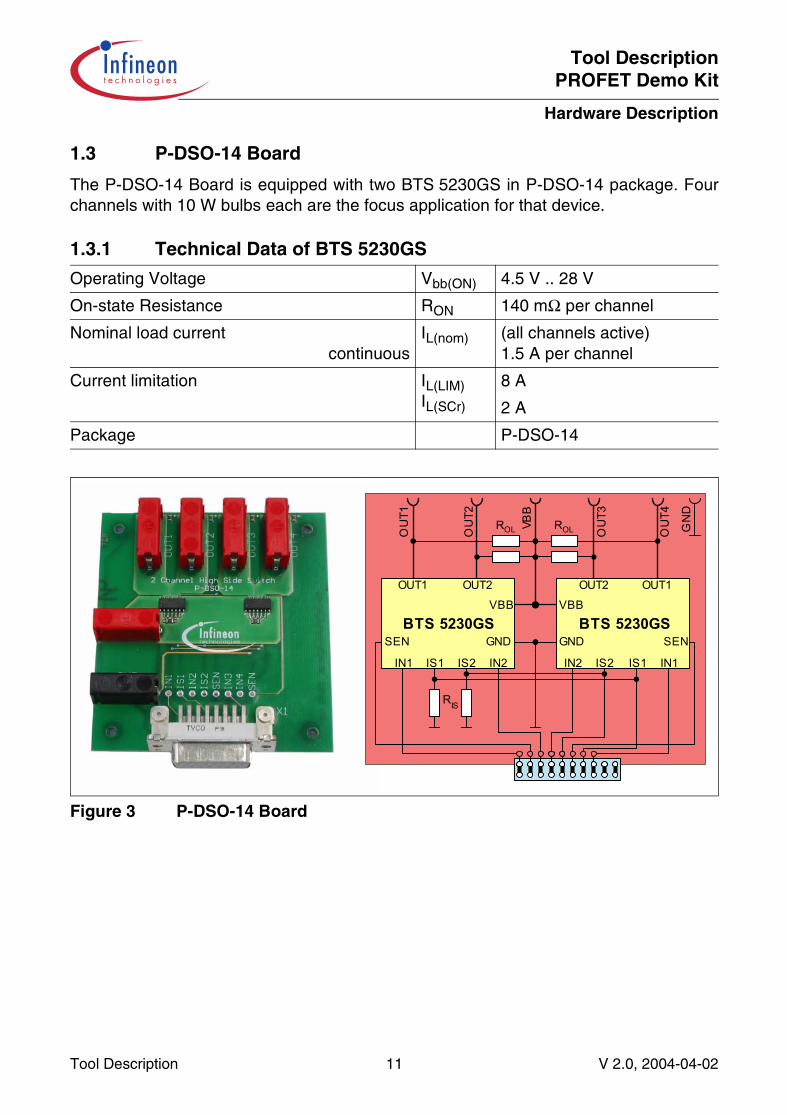
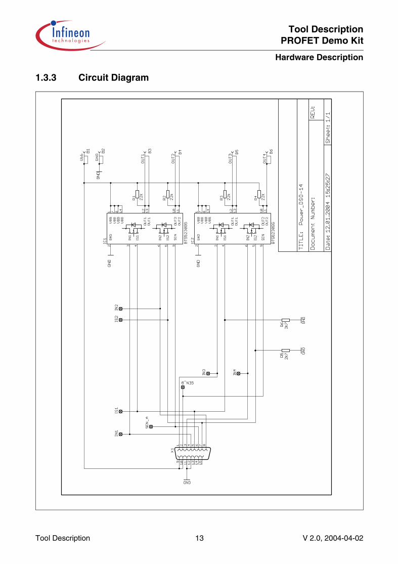
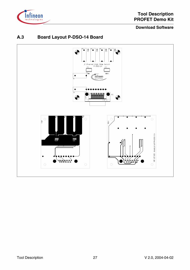
1.3 P-DSO-14 Board
The P-DSO-14 Board is equipped with two BTS 5230GS in P-DSO-14 package. Fourchannels with 10 W bulbs each are the focus application for that device.
Figure 3 P-DSO-14 Board
1.3.1 Technical Data of BTS 5230GS
Operating Voltage Vbb(ON) 4.5 V .. 28 V
On-state Resistance RON 140 mΩ per channel
Nominal load currentcontinuous
IL(nom) (all channels active)1.5 A per channel
Current limitation IL(LIM)IL(SCr)
8 A
2 A
Package P-DSO-14
BTS 5230GSVBB
OUT1
VBB
IN1
SEN
GN
D
OUT2
ROL
IS2IS1 IN2
GND
ROLOU
T1
OU
T2
OU
T3
OU
T4
RIS
BTS 5230GSVBB
OUT1
IN1
SEN
OUT2
IS2 IS1IN2
GND
Tool Description 11 V 2.0, 2004-04-02
Tool DescriptionPROFET Demo Kit
Hardware Description
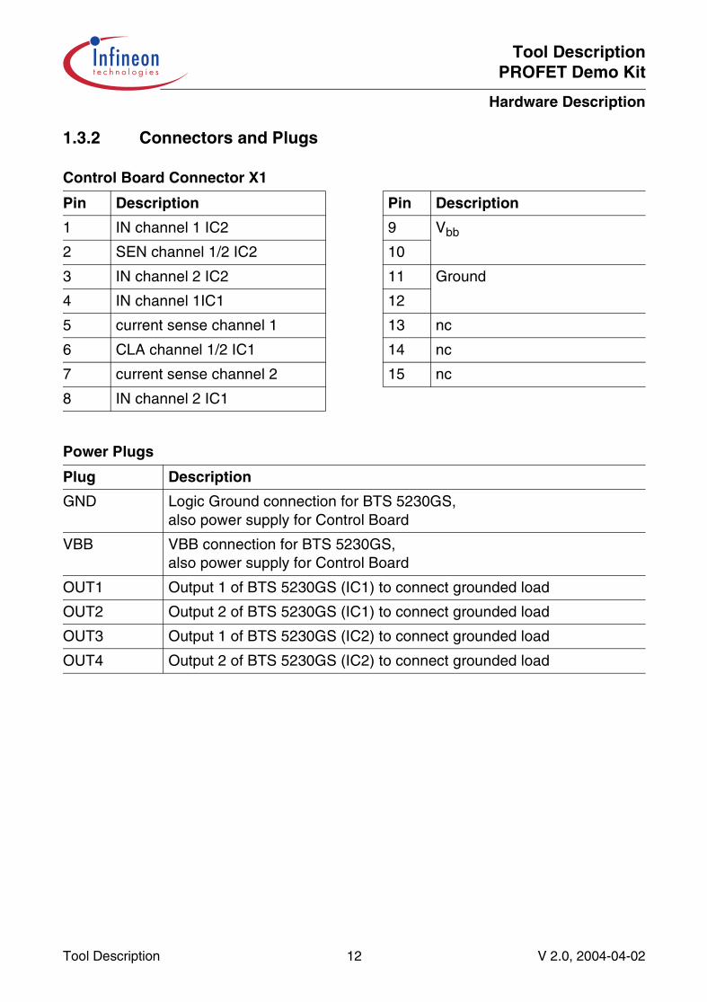
1.3.2 Connectors and Plugs
Control Board Connector X1
Pin Description Pin Description
1 IN channel 1 IC2 9 Vbb
2 SEN channel 1/2 IC2 10
3 IN channel 2 IC2 11 Ground
4 IN channel 1IC1 12
5 current sense channel 1 13 nc
6 CLA channel 1/2 IC1 14 nc
7 current sense channel 2 15 nc
8 IN channel 2 IC1
Power Plugs
Plug Description
GND Logic Ground connection for BTS 5230GS,also power supply for Control Board
VBB VBB connection for BTS 5230GS,also power supply for Control Board
OUT1 Output 1 of BTS 5230GS (IC1) to connect grounded load
OUT2 Output 2 of BTS 5230GS (IC1) to connect grounded load
OUT3 Output 1 of BTS 5230GS (IC2) to connect grounded load
OUT4 Output 2 of BTS 5230GS (IC2) to connect grounded load
Tool Description 12 V 2.0, 2004-04-02
Tool DescriptionPROFET Demo Kit
Hardware Description
1.3.3 Circuit Diagram
Tool Description 13 V 2.0, 2004-04-02
Tool DescriptionPROFET Demo Kit
Hardware Description
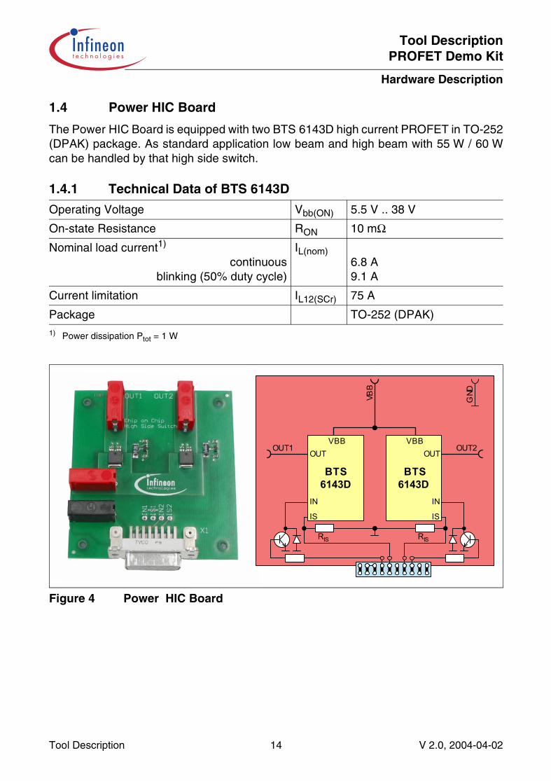
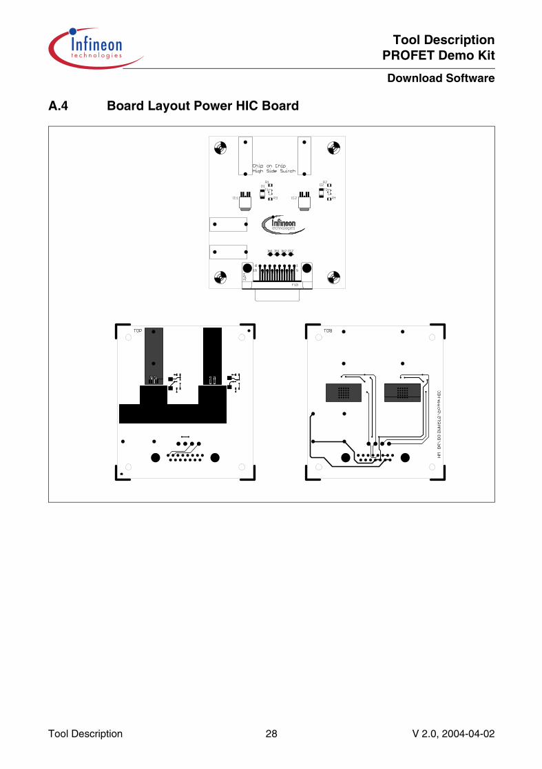
1.4 Power HIC Board
The Power HIC Board is equipped with two BTS 6143D high current PROFET in TO-252(DPAK) package. As standard application low beam and high beam with 55 W / 60 Wcan be handled by that high side switch.
Figure 4 Power HIC Board
1.4.1 Technical Data of BTS 6143D
Operating Voltage Vbb(ON) 5.5 V .. 38 V
On-state Resistance RON 10 mΩNominal load current1)
continuousblinking (50% duty cycle)
1) Power dissipation Ptot = 1 W
IL(nom)6.8 A 9.1 A
Current limitation IL12(SCr) 75 A
Package TO-252 (DPAK)
BTS6143D
BTS6143D
OUT OUTVBB
OUT1
VBB
OUT2
IN IN
IS IS
RIS RIS
GND
VBB
Tool Description 14 V 2.0, 2004-04-02
Tool DescriptionPROFET Demo Kit
Hardware Description
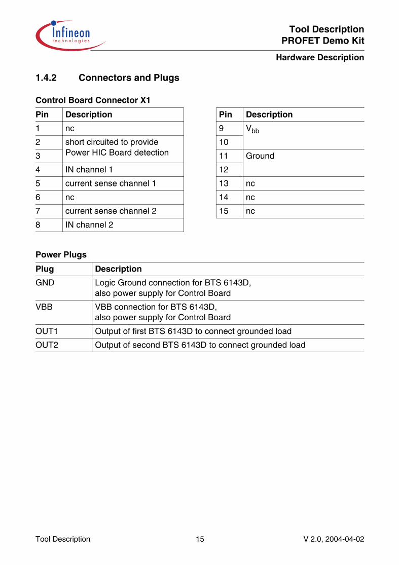
1.4.2 Connectors and Plugs
Control Board Connector X1
Pin Description Pin Description
1 nc 9 Vbb
2 short circuited to provide Power HIC Board detection
10
3 11 Ground
4 IN channel 1 12
5 current sense channel 1 13 nc
6 nc 14 nc
7 current sense channel 2 15 nc
8 IN channel 2
Power Plugs
Plug Description
GND Logic Ground connection for BTS 6143D,also power supply for Control Board
VBB VBB connection for BTS 6143D,also power supply for Control Board
OUT1 Output of first BTS 6143D to connect grounded load
OUT2 Output of second BTS 6143D to connect grounded load
Tool Description 15 V 2.0, 2004-04-02

Tool DescriptionPROFET Demo Kit
Hardware Description
1.4.3 Circuit Diagram
Tool Description 16 V 2.0, 2004-04-02
Tool DescriptionPROFET Demo Kit
Hardware Description
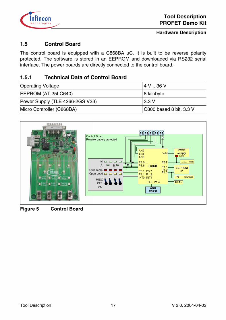
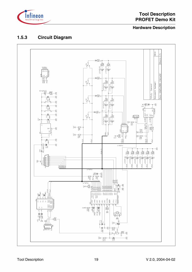
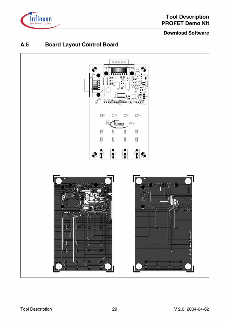
1.5 Control Board
The control board is equipped with a C868BA µC. It is built to be reverse polarityprotected. The software is stored in an EEPROM and downloaded via RS232 serialinterface. The power boards are directly connected to the control board.
Figure 5 Control Board
1.5.1 Technical Data of Control Board
Operating Voltage 4 V .. 36 V
EEPROM (AT 25LC640) 8 kilobyte
Power Supply (TLE 4266-2GS V33) 3.3 V
Micro Controller (C868BA) C800 based 8 bit, 3.3 V
Control BoardReverse battery protected
powersupply
3.3V
XTALP1.0,4
ASCRS232
reset
C868
AN4AN3
RST
VddAN2
EEPROMSPIP1.2
P1.3
P1.1
P1.0, P1.4
P3.0 ...P3.6
P3.1, P3.7P1.1, P1.2INT0, INT1 download
Over TempOpen Load
IN
MISCOFFON
A B
Tool Description 17 V 2.0, 2004-04-02
Tool DescriptionPROFET Demo Kit
Hardware Description
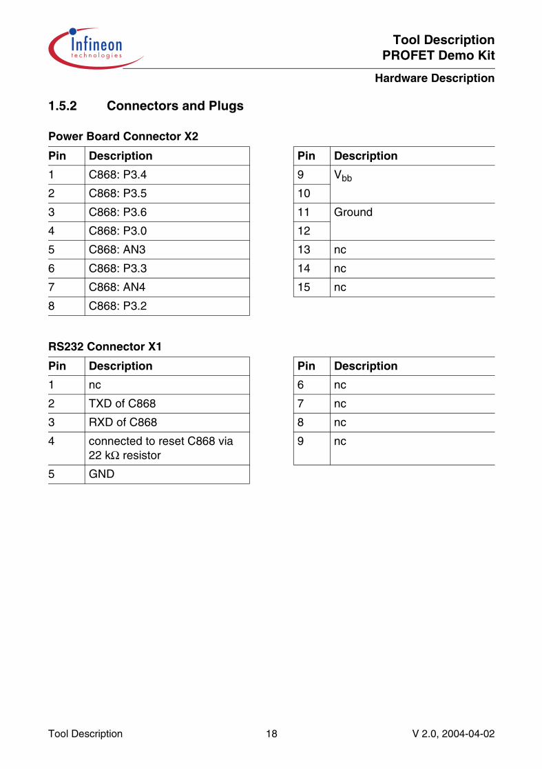
1.5.2 Connectors and Plugs
Power Board Connector X2
Pin Description Pin Description
1 C868: P3.4 9 Vbb
2 C868: P3.5 10
3 C868: P3.6 11 Ground
4 C868: P3.0 12
5 C868: AN3 13 nc
6 C868: P3.3 14 nc
7 C868: AN4 15 nc
8 C868: P3.2
RS232 Connector X1
Pin Description Pin Description
1 nc 6 nc
2 TXD of C868 7 nc
3 RXD of C868 8 nc
4 connected to reset C868 via 22 kΩ resistor
9 nc
5 GND
Tool Description 18 V 2.0, 2004-04-02
Tool DescriptionPROFET Demo Kit
Hardware Description
1.5.3 Circuit Diagram
Tool Description 19 V 2.0, 2004-04-02
Tool DescriptionPROFET Demo Kit
Software Description
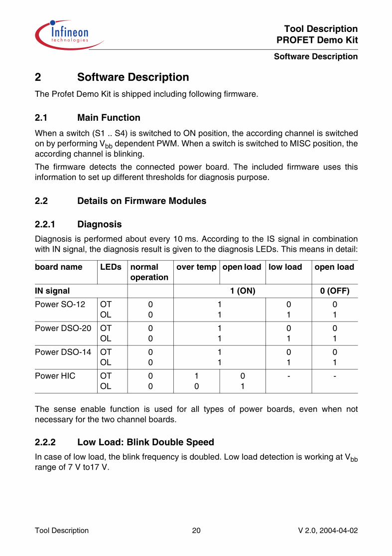
2 Software DescriptionThe Profet Demo Kit is shipped including following firmware.
2.1 Main Function
When a switch (S1 .. S4) is switched to ON position, the according channel is switchedon by performing Vbb dependent PWM. When a switch is switched to MISC position, theaccording channel is blinking.
The firmware detects the connected power board. The included firmware uses thisinformation to set up different thresholds for diagnosis purpose.
2.2 Details on Firmware Modules
2.2.1 Diagnosis
Diagnosis is performed about every 10 ms. According to the IS signal in combinationwith IN signal, the diagnosis result is given to the diagnosis LEDs. This means in detail:
The sense enable function is used for all types of power boards, even when notnecessary for the two channel boards.
2.2.2 Low Load: Blink Double Speed
In case of low load, the blink frequency is doubled. Low load detection is working at Vbbrange of 7 V to17 V.
board name LEDs normal operation
over temp open load low load open load
IN signal 1 (ON) 0 (OFF)
Power SO-12 OTOL
00
11
01
01
Power DSO-20 OTOL
00
11
01
01
Power DSO-14 OTOL
00
11
01
01
Power HIC OTOL
00
10
01
- -
Tool Description 20 V 2.0, 2004-04-02
Tool DescriptionPROFET Demo Kit
Software Description
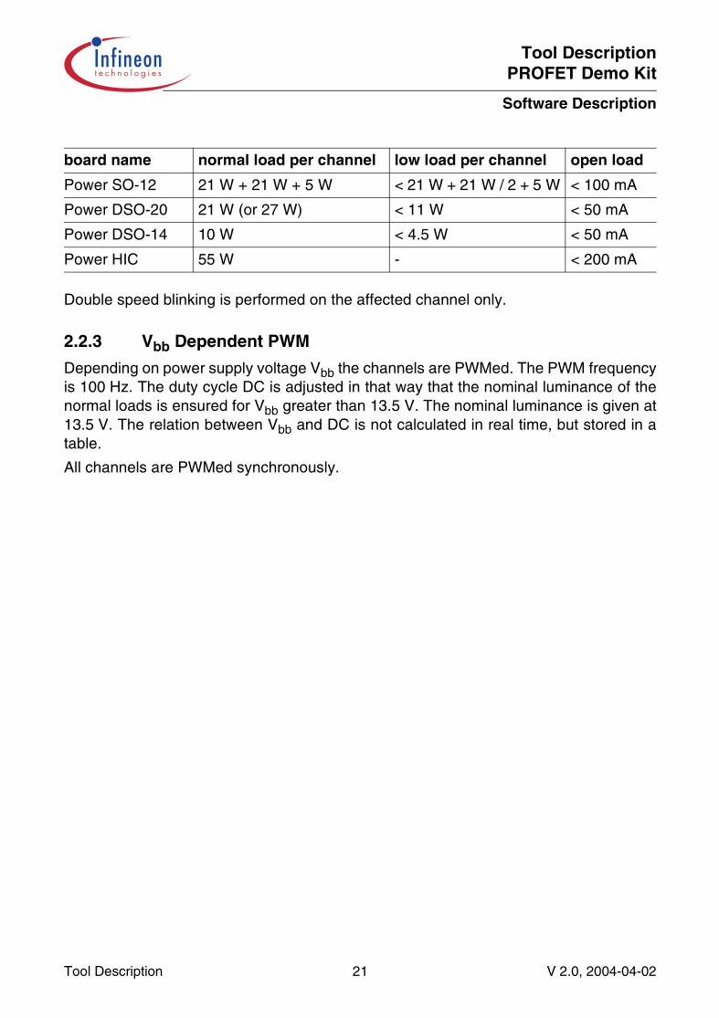
Double speed blinking is performed on the affected channel only.
2.2.3 Vbb Dependent PWM
Depending on power supply voltage Vbb the channels are PWMed. The PWM frequencyis 100 Hz. The duty cycle DC is adjusted in that way that the nominal luminance of thenormal loads is ensured for Vbb greater than 13.5 V. The nominal luminance is given at13.5 V. The relation between Vbb and DC is not calculated in real time, but stored in atable.
All channels are PWMed synchronously.
board name normal load per channel low load per channel open load
Power SO-12 21 W + 21 W + 5 W < 21 W + 21 W / 2 + 5 W < 100 mA
Power DSO-20 21 W (or 27 W) < 11 W < 50 mA
Power DSO-14 10 W < 4.5 W < 50 mA
Power HIC 55 W - < 200 mA
Tool Description 21 V 2.0, 2004-04-02
Tool DescriptionPROFET Demo Kit
Download Software
3 Download SoftwareThe C868 Loader provides an easy way to download software files in intel hex format tothe C868 SRAM or via a special routine to the EEPROM via SPI.
When SRAM is selected, the hex-file is loaded into the SRAM memory area andexecuted immediately. This enables a quick testing of C868 programs.
For a download to the EEPROM, at first, the hex-file is loaded to the SRAM memoryarea. After that, a post loader routine is loaded to the XRAM memory area automatically.After execution in XRAM, the post loader will transfer the bytes stored in SRAM to theEEPROM. To make sure, download has been successful, there is no automatic reset ofthe device.
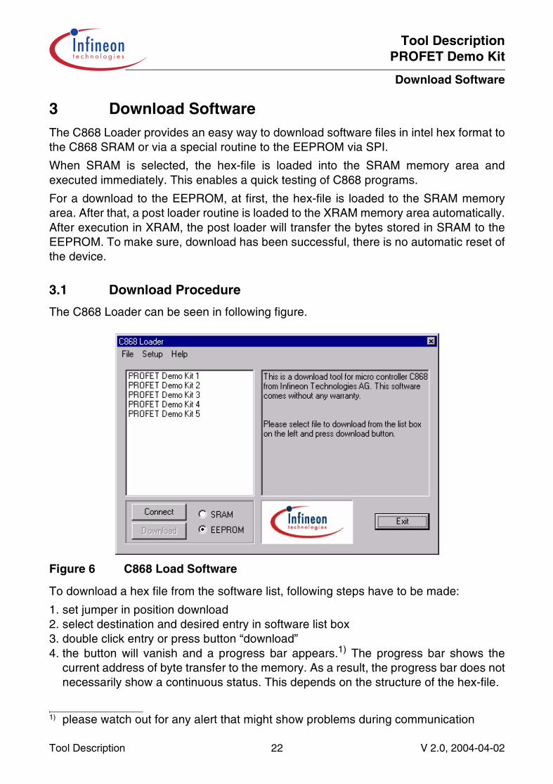
3.1 Download Procedure
The C868 Loader can be seen in following figure.
Figure 6 C868 Load Software
To download a hex file from the software list, following steps have to be made:
1. set jumper in position download2. select destination and desired entry in software list box3. double click entry or press button “download”4. the button will vanish and a progress bar appears.1) The progress bar shows the
current address of byte transfer to the memory. As a result, the progress bar does notnecessarily show a continuous status. This depends on the structure of the hex-file.
1) please watch out for any alert that might show problems during communication
Tool Description 22 V 2.0, 2004-04-02
Tool DescriptionPROFET Demo Kit
Download Software
5. after download has been finished, the progress bar is replaced by the download buttonagain. The loader keeps the target system connected.
6. when destination EEPROM was chosen, set jumper in position normal and cyclebutton “Disconnect“, “Connect”.
The software list box shows all files with extension “.hex”. It is filled at program startuponly. When there is a file with the same filename but extension “.txt”, a description isshown as soon as the entry is selected in the software list box.
3.2 Using DTR Line as Reset Signal
The DTR handshake line is used to reset the micro controller. The button “Connect”provides a mechanism to change the level of that handshake line.
• Button shows “Connect”: The level at DTR is -12 V or high impedance1)
• Button shows “Disconnect”: The level at DTR is +12 V, system is running
During Download, the DTR line is handled automatically. It is set to -12 V for about200 ms. After that, the level is raised to +12 V and the system waits about 200 ms againto ensure that the hardware did setup all other levels. Now download begins. Afterdownload has been finished, the loader changes to connect state automatically.
When automatic reset handling should be disabled, resistor R12 has to be removed.
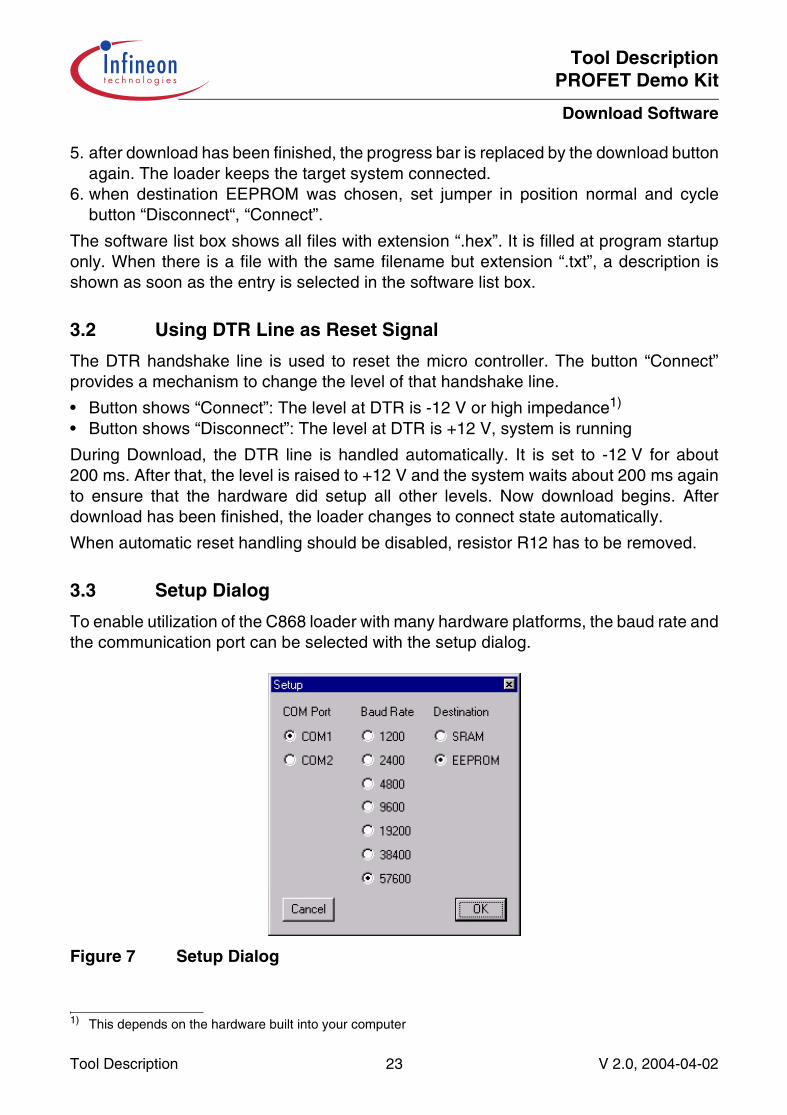
3.3 Setup Dialog
To enable utilization of the C868 loader with many hardware platforms, the baud rate andthe communication port can be selected with the setup dialog.
Figure 7 Setup Dialog
1) This depends on the hardware built into your computer
Tool Description 23 V 2.0, 2004-04-02
Tool DescriptionPROFET Demo Kit
Download Software
The supported communication ports are COM1 and COM2, which are opened atdownload or during running system (button shows “Disconnect”). When system is notrunning (disconnected) and no download is performed, the communication port is closedand can be used by other software.
The baud rate can be selected from 1200 baud to 56700 baud. Please note that thereare limits for proper data transfer given by the realization of the RS232 circuits at C868hardware platform.
The destination selector shows the same status as the destination selector at the mainwindow.
Tool Description 24 V 2.0, 2004-04-02
Tool DescriptionPROFET Demo Kit
Download Software
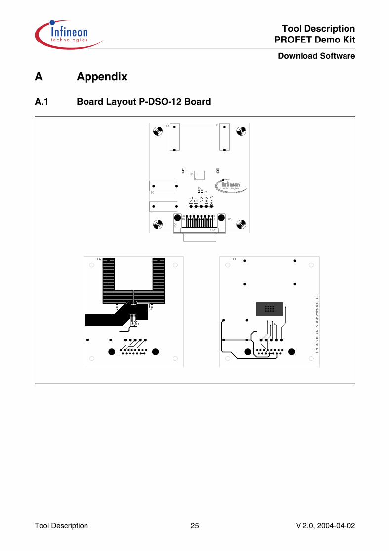
A Appendix
A.1 Board Layout P-DSO-12 Board
Tool Description 25 V 2.0, 2004-04-02
Tool DescriptionPROFET Demo Kit
Download Software
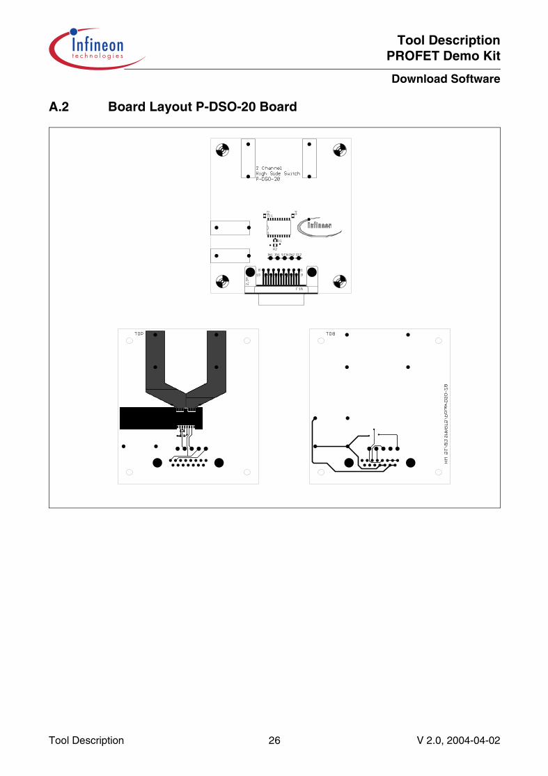
A.2 Board Layout P-DSO-20 Board
Tool Description 26 V 2.0, 2004-04-02
Tool DescriptionPROFET Demo Kit
Download Software
A.3 Board Layout P-DSO-14 Board
Tool Description 27 V 2.0, 2004-04-02
Tool DescriptionPROFET Demo Kit
Download Software
A.4 Board Layout Power HIC Board
Tool Description 28 V 2.0, 2004-04-02
Tool DescriptionPROFET Demo Kit
Download Software
A.5 Board Layout Control Board
Tool Description 29 V 2.0, 2004-04-02
Tool DescriptionPROFET Demo Kit
Download Software
Tool Description 30 V 2.0, 2004-04-02

Edition 2004-04-02
Published by Infineon Technologies AG,St.-Martin-Strasse 53,81669 München, Germany
© Infineon Technologies AG 2004.All Rights Reserved.
Attention please!
The information herein is given to describe certain components and shall not be considered as warranted characteristics.Terms of delivery and rights to technical change reserved.We hereby disclaim any and all warranties, including but not limited to warranties of non-infringement, regarding circuits, descriptions and charts stated herein.Infineon Technologies is an approved CECC manufacturer.
Information
For further information on technology, delivery terms and conditions and prices please contact your nearest Infineon Technologies Office in Germany or our Infineon Technologies Representatives worldwide (www.infineon.com).
Warnings
Due to technical requirements components may contain dangerous substances. For information on the types in question please contact your nearest Infineon Technologies Office.Infineon Technologies Components may only be used in life-support devices or systems with the express written approval of Infineon Technologies, if a failure of such components can reasonably be expected to cause the failure of that life-support device or system, or to affect the safety or effectiveness of that device or system. Life support devices or systems are intended to be implanted in the human body, or to support and/or maintain and sustain and/or protect human life. If they fail, it is reasonable to assume that the health of the user or other persons may be endangered.

Qualität hat für uns eine umfassende Bedeutung. Wir wollen allen Ihren Ansprüchen in der bestmöglichen Weise gerecht werden. Es geht uns also nicht nur um die Produktqualität – unsere Anstrengungen gelten gleichermaßen der Lieferqualität und Logistik, dem Service und Support sowie allen sonstigen Beratungs- und Betreuungsleistungen.
Dazu gehört eine bestimmte Geisteshaltung unserer Mitarbeiter. Total Quality im Denken und Handeln gegenüber Kollegen, Lieferanten und Ihnen, unserem Kunden. Unsere Leitlinie ist jede Aufgabe mit „Null Fehlern“ zu lösen – in offener Sichtweise auch über den eigenen Arbeitsplatz hinaus – und uns ständig zu verbessern.
Unternehmensweit orientieren wir uns dabei auch an „top“ (Time Optimized Processes), um Ihnen durch größere Schnelligkeit den entscheidenden Wettbewerbsvorsprung zu verschaffen.
Geben Sie uns die Chance, hohe Leistung durch umfassende Qualität zu beweisen.
Wir werden Sie überzeugen.
Quality takes on an allencompassing significance at Semiconductor Group. For us it means living up to each and every one of your demands in the best possible way. So we are not only concerned with product quality. We direct our efforts equally at quality of supply and logistics, service and support, as well as all the other ways in which we advise and attend to you.
Part of this is the very special attitude of our staff. Total Quality in thought and deed, towards co-workers, suppliers and you, our customer. Our guideline is “do everything with zero defects”, in an open manner that is demonstrated beyond your immediate workplace, and to constantly improve.
Throughout the corporation we also think in terms of Time Optimized Processes (top), greater speed on our part to give you that decisive competitive edge.
Give us the chance to prove the best of performance through the best of quality – you will be convinced.
h t t p : / / w w w . i n f i n e o n . c o m
Total Quality Management
Published by Infineon Technologies AG