Embed Size (px)
Citation preview

2-Wheeler starter relay with Power PROFET™
BTS50010-1TAE
About this documentScope and purpose
This application note presents the Infineon power PROFET™ BTS50010-1TAE used as Solid State Relay (SSR) todrive the starter motor of a scooter or a motorcycle (engine smaller than 150 cc).A typical application diagram is presented and measurement results are discussed. Critical failure conditions(reverse battery connection, loss of supply) are described and solutions are proposed to protectBTS50010-1TAE.Finally, the integration with the vehicle Engine Control Unit (ECU) is discussed and the demoboard is described.Intended audience
OEMs manufacturing scooters and motorcycles with an engine smaller than 150 cc, their Tiers 1 and Tiers 2providing equipment for such 2-wheelers, looking for electromechanical relay replacement by a siliconsolution.
Table of contents
About this document . . . . . . . . . . . . . . . . . . . . . . . . . . . . . . . . . . . . . . . . . . . . . . . . . . . . . . . . . . . . . . . . . . . 1
1 Introduction to Scooter Starter Relay . . . . . . . . . . . . . . . . . . . . . . . . . . . . . . . . . . . . . . . . . . . . . . . . . . . . 2
2 Using Infineon PROFET™ BTS50010-1TAE as SSR for scooters and motorcycles . . . . . . . . . . . . . 4
3 Driving a small ICE starter motor (< 150 cc) . . . . . . . . . . . . . . . . . . . . . . . . . . . . . . . . . . . . . . . . . . . . . . .63.1 Application diagram . . . . . . . . . . . . . . . . . . . . . . . . . . . . . . . . . . . . . . . . . . . . . . . . . . . . . . . . . . . . . . . . . . . . . 63.2 Switching waveforms . . . . . . . . . . . . . . . . . . . . . . . . . . . . . . . . . . . . . . . . . . . . . . . . . . . . . . . . . . . . . . . . . . . . 73.3 Loop inductance estimation via data curve fitting . . . . . . . . . . . . . . . . . . . . . . . . . . . . . . . . . . . . . . . . . 103.4 Switching-OFF behaviour . . . . . . . . . . . . . . . . . . . . . . . . . . . . . . . . . . . . . . . . . . . . . . . . . . . . . . . . . . . . . . . 113.5 Current sensing . . . . . . . . . . . . . . . . . . . . . . . . . . . . . . . . . . . . . . . . . . . . . . . . . . . . . . . . . . . . . . . . . . . . . . . . 193.6 Undervoltage protection . . . . . . . . . . . . . . . . . . . . . . . . . . . . . . . . . . . . . . . . . . . . . . . . . . . . . . . . . . . . . . . . 213.7 Battery disconnection . . . . . . . . . . . . . . . . . . . . . . . . . . . . . . . . . . . . . . . . . . . . . . . . . . . . . . . . . . . . . . . . . . 223.8 Reverse battery protection . . . . . . . . . . . . . . . . . . . . . . . . . . . . . . . . . . . . . . . . . . . . . . . . . . . . . . . . . . . . . . 24
4 Practical considerations . . . . . . . . . . . . . . . . . . . . . . . . . . . . . . . . . . . . . . . . . . . . . . . . . . . . . . . . . . . . . . . 264.1 ECU integration (space estimation) . . . . . . . . . . . . . . . . . . . . . . . . . . . . . . . . . . . . . . . . . . . . . . . . . . . . . . .264.2 Demoboard . . . . . . . . . . . . . . . . . . . . . . . . . . . . . . . . . . . . . . . . . . . . . . . . . . . . . . . . . . . . . . . . . . . . . . . . . . . . 28
5 Reference list . . . . . . . . . . . . . . . . . . . . . . . . . . . . . . . . . . . . . . . . . . . . . . . . . . . . . . . . . . . . . . . . . . . . . . . . . .30
6 Revision history . . . . . . . . . . . . . . . . . . . . . . . . . . . . . . . . . . . . . . . . . . . . . . . . . . . . . . . . . . . . . . . . . . . . . . . 31
Disclaimer . . . . . . . . . . . . . . . . . . . . . . . . . . . . . . . . . . . . . . . . . . . . . . . . . . . . . . . . . . . . . . . . . . . . . . . . . . . . 32
Z8F64996718
Application Note Please read the Important Notice and Warnings at the end of this documentwww.infineon.com
Rev. 1.11 2022-01-10

1 Introduction to Scooter Starter RelayIn general, an Internal Combustion Engine (ICE) starter motor is a machine used to provide the initial torque(crank) for the main combustion engine for few mechanical cycles. It is also known as a cranking motor orsimply as a starter.For motorcycles or scooters with engines smaller than 150 cc, the most known solution is a small DC brushedmotor. Such motors are attractive due to their relatively small size, torque ratio, simplicity and costeffectiveness.The challenge comes from the low voltage generated by the on board battery: 12 V. Indeed, the torque requiredto activate the combustion engine during the first few cranks is very high, which means that the electrical powerrequired is also very high. This translate into a very high current since the battery voltage is rather low. Forengines below 150 cc, the inrush current to be delivered to the starter can go up to 250 A.The logic circuit connected to the relay control coil defines the operation of the mechanical contact of the relay.There are very often three switches:• Engine stop switch (normally on): this mechanical switch is usually unlocked by the user through a
mechanical key. The key needs to be inserted and activated to power-up the motor cycle. It is then possibleto start the Internal Combustion Engine
• Ignition switch (normally off): this is a push button, in general, which is activated by the user to start theengine. This button will not operate if the motor cycle is not yet powered up thanks to the main key
• Kickstand stop switch: there is at least one security on the ignition circuit: if the lateral kickstand isunlocked, it is necessary to prevent the Internal Combustion Engine to start for safety reasons. A dedicatedswitch is used to sense if the kickstand is locked or not
Besides these switches, a fuse protects the power path from the battery to the starter Motor.The system described above is illustrated in Figure 1.
chassis
M
Battery12.0V
StarterRelay
IgnitionSwitch
Kickstand stop switch
Fuse
Engine Stop
Switch
StarterMotor
Figure 1 Starter relay basic circuit schematics
The system described in the Figure 1 is straightforward and elementary; there are many variants in the marketand the target here is not to describe all of them. The intention is to highlight the most common building blocksand to discuss some of the drawbacks inherent to its electromagnetic structure.
2-Wheeler starter relay with Power PROFET™BTS50010-1TAE
1 Introduction to Scooter Starter Relay
Application Note 2 Rev. 1.11 2022-01-10

Due to the high inrush current at start-up and the high energy at switch-off coming from the demagnetization ofthe motor inductance, the electromechanical relays survive in the range of 50 000 ON-OFF cycles. In countrieswhere the people are asked to switch off their engine anytime their motorcycle is stopped (traffic jams, lightsetc.), such a low number of cycles provides approximately 3.5 years lifetime. A lot of users do therefore have toreplace their relay over the lifetime of their motorcycle.For some intensive users, this time could even be reduced such that it falls inside the warranty time specified bythe Original Equipment Manufacturer (OEM). The OEM has then to cover the replacement expenses.Using a solid state relay such as the BTS50010-1TAE is an easy and cost effective way to extend the life time ofthe starter relay, since the number of ON-OFF cycles can go beyond 1 million cycles.It is also consistent with the current trends in motor control, where electronically-controlled fuel injectionbecomes a must due to the strong regulations on CO2 emissions everywhere on the globe. Since an ElectronicControl Unit (ECU) for motor control has to be integrated on any motorcycle, it becomes easier to use anelectronic component to replace the starter relay since it can be located on that ECU.
2-Wheeler starter relay with Power PROFET™BTS50010-1TAE
1 Introduction to Scooter Starter Relay
Application Note 3 Rev. 1.11 2022-01-10

2 Using Infineon PROFET™ BTS50010-1TAE as SSR for scootersand motorcycles
Power PROFET™ (PROtected MOSFET) is a family of benchmark high side switches, dedicated to relay and fusereplacement for high current applications. Specifically, BTS50010-1TAE is a 1 mΩ single channel smart high-side power switch, embedded in a D2PAK 7-pin package, providing protective functions and diagnosis. Thepower transistor is built by an N-channel power MOSFET with charge pump.The provided protections and diagnosis functionalities include:• Undervoltage shutdown (threshold is 5 V ± 0.5 V)• Reverse battery protection by turning on the internal MOSFET• Secure load turn-off during loss of ground (GND)• Overtemperature and overcurrent (short circuit) protection with latch-off mechanismA block diagram illustrating the overall functionalities of the BRS50010-1TAE [1] is shown in Figure 2.
VS
OUT
Smart Clamp
OvercurrentSwitch OFF
Gate Control&
Charge Pump
Load Current Sensing
OverTemperature
Voltage Sensing
RVS
DriverLogic
GND
ESDProtection
IN
IS
InternalPowerSupply
Power and drivers
Sensing
Peripherals
Figure 2 Block Diagram for the BTS50010-1TAE
The use of the BTS50010-1TAE brings reduced volume and weight (below 1.5 g): it is unbeatable in comparisonto the bulky starter relays (4 g to 40 g).In the harsh motorcycle environment, electrical failures may happen intermittently due to mechanical stress,unstable wire connections, customer errors and also aging. With electromechanical solutions based on relayand fuse, in the event of a short-circuit, the fuse has to be replaced. With BTS50010-1TAE, the system isprotected against short-circuits without the need to replace any part: once the short is removed, the protectionscan be reset. This is managed electrically, through the Input control signal of BTS50010-1TAE.
2-Wheeler starter relay with Power PROFET™BTS50010-1TAE
2 Using Infineon PROFET™ BTS50010-1TAE as SSR for scooters and motorcycles
Application Note 4 Rev. 1.11 2022-01-10

Table 1 Comparison features between the relay and fuse system and PROFET™ SSR solution
Relay BTS50010-1TAE SSR
Immunity to aging Low Higher
Immunity to corrosion No Yes
High number of cycles capability No Yes
Microcontroller direct drivability No Yes
Self-Protection Once Resettable
Diagnosis No Yes
Efficiency Low High
2-Wheeler starter relay with Power PROFET™BTS50010-1TAE
2 Using Infineon PROFET™ BTS50010-1TAE as SSR for scooters and motorcycles
Application Note 5 Rev. 1.11 2022-01-10

3 Driving a small ICE starter motor (< 150 cc)
3.1 Application diagramFigure 3 shows a possible implementation of an SSR for starter motor used on motorcycles with a small engine(< 150 cc). This diagram presents two options for the SSR control:1. No microcontroller is present, the ignition order is given through a mechanical switch connected to
RIN_PU and RIN_PD resistor divider2. A microcontroller is present, typically the one on the ICE control ECU, which interfaces with
BTS50010-1TAE to trigger the engine cranking (through pin IN) and monitors the load current andprotection status (through pin IS). A few passive components are used between the microcontroller andBTS50010-1TAE, either for filtering reasons (CIS_Filt), for protection in case of reverse battery polarity(RIS_prot and RIN) or to convert the sense current into a voltage which can be sampled by an Analog toDigital (A/D) converter in the microcontroller (RIS)
IN
IS
GND
OUT
VS
COUT
RCABLE, LCABLE
Load MRIS
GPIO
A/D IN
VSS
VDD
Micro controller
VDDCVS
RSUPPLY, LSUPPLY
VBAT
DZ1
Optional elements marked in grey
CIN
RGND
CIS_FILT
RIS_prot
RIN
RIN_PD
RIN_PU
Configuration without MicroController
Configuration with MicroController
Figure 3 Application diagram with the BTS50010-1TAE
Whatever the control option (with or without microcontroller), there are a few mandatory passive components:• Supply filtering: CVS• Protection against loss of Supply and Loss of Load: DZ1 (see section 5.3.2 in BTS50010-1TAE datasheet [1])• Input Filtering: CIN• EMC and ESD protection: COUT• Reverse battery protection: RGND
2-Wheeler starter relay with Power PROFET™BTS50010-1TAE
3 Driving a small ICE starter motor (< 150 cc)
Application Note 6 Rev. 1.11 2022-01-10

Table 2 Component values
Reference Value PurposeRGND 10 Ω Protection in case of overvoltage and loss of battery while driving
inductive loads
DZ1 VBR = 40 V Suppressor (TVS) diode. Protection during overvoltage and incase of loss of battery while driving inductive loads. More detailsin Chapter 3.7
CVS 100 nF Improved EMC behaviour (in layout, please place close to thepins)
COUT 10 nF Improved EMC behaviour (in layout, please place close to thepins)
CIN 150 nF Together with RIN, CIN ensures that the voltage applied on IN pin isdelayed compared to a rising edge on the supply (VS pin)
RIN_PD 4.7 kΩ Fast discharge of CIN
RIN 4.7 kΩ Protection of the microcontroller during transient pulses andreverse polarity
RIS 1 kΩ Sense resistor; if IS signal is not used, leave IS pin open
RIS_PROT 4.7 kΩ Protection of the microcontroller during overvoltageProtection of the BTS50010-1TAE during reverse polarity
CIS_FILT 10 nF Sense signal filtering
In the next chapters, several measurements will be discussed in a real case where BTS50010-1TAE is used as amotor starter silicon-based relay. For all these tests, the motor used to emulate a motor starter silicon-basedrelay is a 12 V 0.35 kW DC-brushed machine.The schematic is derived from the one illustrated on Figure 3.
3.2 Switching waveformsThe target of the test shown here is to illustrate waveforms during regular switch ON and OFF on the motorstarter load.During these switching tests, the rotor of the electrical machine is kept locked, simulating a blocked motor.Indeed, this is the worst condition in terms of current (stall current can be as high as 250 A) and as a result,generates a severe inductive demagnetization pulse when the BTS50010-1TAE is driven to switch OFF. Thiscurrent is limited by four main parameters:• the battery voltage• the battery output resistance• the wiring resistance• the motor series resistanceTo have the flexibility to control this current, the test set up has been defined based on a battery emulatorrather than a real 12 V motorcycle battery. This emulator is built with a powerful power supply followed by aresistor bank. It allows to easily configure the supply voltage and the emulated battery output resistance andthe wiring resistance.
2-Wheeler starter relay with Power PROFET™BTS50010-1TAE
3 Driving a small ICE starter motor (< 150 cc)
Application Note 7 Rev. 1.11 2022-01-10

Bank of high power resistors
M StarterMotor
BTS50010-1TAETest Board
Power Supply
+ -
Figure 4 Battery emulator, built with a power supply followed by a resistor bank
BTS50010-1TAE is activated via the IN signal (active High), as it is illustrated in the Figure 5.
ON time
Inductive clamping at switch OFF
IL scale: 100A/DivIS scale: 2mA/Div
250A5mA
0A0A
Figure 5 Switching behavior of the BTS50010-1TAE
The pulse duration applied on the IN pin of the BTS50010-1TAE is approximately 35 ms long. Such short pulsewidth was selected in order to only verify the waveforms behavior during the current rise and falling edges. Inthe next chapters, more realistic values for the pulse duration will be considered to check the behavior during amotor stall condition (from 1 s to 2 s for load current equals to 250 A).
2-Wheeler starter relay with Power PROFET™BTS50010-1TAE
3 Driving a small ICE starter motor (< 150 cc)
Application Note 8 Rev. 1.11 2022-01-10
During the time the device is enabled, the load current IL rises to the motor in-rush current value since the rotoris mechanically blocked: roughly 250 A. Since the device is enabled, the drain-to-source voltage is defined byRDS(ON)∙ IL and there is a noticeable voltage drop on the input pin VS due the emulated battery resistance plusthe cable resistances (VS drops to approximately 8 V).Figure 6 shows a zoom on the switch ON phase:
IL scale: 100A/Div
IS scale: 2mA/Div
0A0A
Figure 6 Switch ON event
At switch off, due to the motor inductance and the cables parasitic inductance, the device is driven toavalanche, and the voltage is clamped at a value slightly larger than 40 V. During this phase, the device isdissipating the very high energy accumulated in the inductances in the system. This is discussed further in Chapter 3.4.For the time being, we have first to estimate the motor inductance.
2-Wheeler starter relay with Power PROFET™BTS50010-1TAE
3 Driving a small ICE starter motor (< 150 cc)
Application Note 9 Rev. 1.11 2022-01-10

3.3 Loop inductance estimation via data curve fittingDifferent method can be used to estimate the loop inductance parameters.The one selected here requires a curve fitting algorithm for the acquired oscilloscope data. At first, it isconsidered that, in the current loop, one can approximate the behavior of the load current as a simple firstorder RL circuit. Then, the equation considered for the curve fitting iterations is the exponential function givenby the equation:
IL t = Io 1 − e− −tτ
Equation 1
Where IL is the load current, Io is the steady state value for the load current and τ is the load time constant. Foran inductor, the time constant is defined as: τ = L
RS where L is the motor inductance and RS is the motor series
resistance.The time t considered in Equation 1 is specified to be 0 at the origin.In order to guarantee that the fitting curve algorithm converges, only the rising edge of the acquired current isused as input data. The easiest way is to limit the acquisition performed by the oscilloscope to the rising edge,with the beginning of the edge positioned at the left origin of the display.For the present study the current waveform and the curve fitting results are compared and they are illustratedin the chart in the Figure 7. The measured load current is the black trace and the associated fitted curve is givenby the red trace.
Figure 7 Curve fitting results for the loop inductance estimationThe hashed grey area in the chart illustrates the points excluded from the fitting process.Once computed, the fitting process leads to the following values (with a reasonable error, as displayed in blueon Figure 7 ):• The steady state current value is: I0 = 252 A (value for t > 0.6 s)• The steady state output voltage is: VOUT = 7.4 V (value for t > 0.6 s)• The time constant is: τ = 890 µsThe calculated total resistance (including the cables and the motor series resistance) is:
2-Wheeler starter relay with Power PROFET™BTS50010-1TAE
3 Driving a small ICE starter motor (< 150 cc)
Application Note 10 Rev. 1.11 2022-01-10

RTOT = VOUT / I0 = 7.4 / 252 = 29 mΩ.From the time constant t and the total resistance, the loop inductance is:LTOT = RTOT x τ = 890.10e-6 x 29.10e-3 = 26 µH.
3.4 Switching-OFF behaviourAs it is described in section 5.1.3 of BTS50010-1TAE datasheet [1], when switching off on an inductive load,there is a demagnetization phase during which the PROFET™ is in smart clamping. Indeed, in order for thecurrent in the inductance to decrease, the voltage polarity on the motor terminal has to be reversed andBTS50010-1TAE applies a negative voltage VDEMAG = - [VDS(CL) - VS] (around - 25 V at the end of a regular startup).The associated power represents several kiloWatts, fortunately limited to a fraction of a millisecond.The high power injected in the MOSFET generates a significant temperature increase. It is therefore necessary tocheck if this stress may damage the BTS50010-1TAE or not.The way to proceed here is as follows:1. First, define the worst case condition in terms of current at switch OFF2. Check if the condition may apply many times over the lifetime of the device or only a very limited
number of timesa. If it applies many times, use the EAR curve as plotted in figure 5, section 4.1 of the BTS50010-1TAE
datasheet [1]b. If it applies a handful of times, then use the EAS curve from the same figure 5
3. Calculate the energy dissipated inside the device using the formula 5.1 defined in section 5.1.3.2 of theBTS50010-1TAE datasheet [1]
4. Check if this energy level is compatible with either the EAR or the EAS curve, as appropriateThe worst case condition to consider is when the PROFET™ switches OFF while the starter motor is in stallcondition as illustrated on Figure 8 :
IMotor
t
Inrush @ Start-up
Motor running (back EMF)
Motor unpowered
250A
IMotor
t
Stallmotor
Motor unpowered
250ACurrent@switch OFF
Current@switch OFF
Figure 8 Starter motor current profile in regular start–up (left) and in stall condition (right)Our assumption here is that the current in blocked mode can be 250 A. This is a failure mode, which should takeplace a very limited number of time over the lifetime of the motorcycle: the EAS curve can be used here.The switch OFF will very likely be generated by the overtemperature protection. Indeed, the power dissipationinside BTS50010-1TAE to deliver 250 A is very high, which leads to a significant increase of the MOSFETtemperature. The thermal simulation on Figure 9 shows that the MOSFET temperature is above 150°C after lessthan 0.8 s at 250 A load current, starting from an ambient temperature of 25°C. So if the control signal on the INpin is high for more than 0.8 s, the component will switch OFF due to the over temperature protection. It ishighly recommended to monitor the IS pin signal once the device is turned ON: as described in Chapter 3.5, thissignal allows to know the load current and it is therefore possible to decide to switch OFF BTS50010-1TAE if the
2-Wheeler starter relay with Power PROFET™BTS50010-1TAE
3 Driving a small ICE starter motor (< 150 cc)
Application Note 11 Rev. 1.11 2022-01-10

current if high for a longer time than a standard inrush. In such a way, the temperature increase inBTS50010-1TAE is reduced and its lifetime is extended.
Figure 9 Thermal simulation in stall condition (250 A) assuming a 4-layer PCB (JEDEC 2s2p)
When the switch OFF is triggered by the over temperature protection, the junction temperature of the MOSFETat the beginning of the demagnetization is above 150°C, which shifts the smart clamping voltage to roughlyVDS(CL) = 42 V.The demagnetization energy can be calculated because of the following equation and the associatedparameters values:
E = VDS CL × LRL
×Vs − VDS CL
RL× ln 1 −
RL − ILVS − VDS CL
+ IL
Equation 2Where: VDS(CL) = 42 V (due to the high temperature of the MOSFET); L = 26 µH; RL = 29 mΩ; VS = 8 V (due to thevoltage drop in the battery output resistance); IL = 250 A.The result is: E = 880 mJ.Looking at the EAS curve from the datasheet [1], it is visible that this level of energy can damage BTS50010-TAE:
2-Wheeler starter relay with Power PROFET™BTS50010-1TAE
3 Driving a small ICE starter motor (< 150 cc)
Application Note 12 Rev. 1.11 2022-01-10
x

880mJ
450mJ
Device safeEAS @ 250A
Energy injected by the starter motor @ 250A
Figure 10 Checking the safety margin at 250 AThis is only an example based on the characteristics of the starter motor used here in the tests and simulating astall current of 250 A. It may be that with other motor characteristics (inductance, resistance, stall current), thecomponent is in the safe operating area for EAS.For instance, recomputing the energy if the maximum stall current is changed from 250 A to 200 A, every otherparameter remaining unchanged, and the energy injected in the MOSFET becomes 580 mJ at 200 A:
580mJ
600mJ
Device safeEAS @ 200A
Energy injected by the starter motor @ 200A
Figure 11 Checking the safety margin at 200 AThis time, the device is safe, the energy injected is smaller than the maximum EAS specified at 200 A.Back to the scenario with 250 A, since the device can be damaged, it is necessary to add external protections.The target with such protections is to offload part of the demagnetization energy from BTS50010-1TAE.
2-Wheeler starter relay with Power PROFET™BTS50010-1TAE
3 Driving a small ICE starter motor (< 150 cc)
Application Note 13 Rev. 1.11 2022-01-10

The proposal is to use a bi-directional Transient Voltage Suppressor (TVS) between the MOSFET drain (VS pin)and the MOSFET source (OUT pins). A series resistor is also added, to fine tune the sharing of the energybetween the TVS and BTS50010-1TAE.Table 3 shows the new application schematic with DZ2 and RZ2. (DZ1 has not yet been discussed: it will bedescribed later on).
IN
IS
GND
OUT
VS
C OUT
R CABLE , L CABLE
Load MRIS
GPIO
A/ D IN
VSS
VDD
Micro controller
VDDC VS
R SUPPLY , L SUPPLY
V BAT
DZ1
Optional elements marked in grey
CIN
RGND
CIS_FILT
RIS_prot
RIN
RIN_PD
RIN_PU
Configuration without
MicroController
Configuration with MicroController
DZ2
RZ2
Figure 12 Application diagram with auxiliary drain-to-source snubber circuitry (RZ2 and DZ2)The target now is to determine which TVS to select for DZ2 and which value to assign to RZ2 so that the energy isshared among the 3 devices and all of them are in their safe operating area.The first step is to understand better how these two components behave: the smart clamping feature ofBTS50010-1TAE and the TVS both behave as an ideal zener diode in series with a low-ohmic resistor; since anexternal resistor (RZ2) is added in series with the TVS, the equivalent schematic is:
Ideal zener diode
Series resistanceRS_SmCl
VDS(CL)
Ideal zener diode
Series resistanceRS_DZ2
VDz2
RZ2
Smart clamping TVS (DZ2) + RZ2
VS
OUTISmCl IDz2
Figure 13 Equivalent schematic for the smart clamping and the TVS
2-Wheeler starter relay with Power PROFET™BTS50010-1TAE
3 Driving a small ICE starter motor (< 150 cc)
Application Note 14 Rev. 1.11 2022-01-10

Since the smart clamping feature of BTS50010-1TAE and the network formed by the TVS (DZ2) and RZ2 areconnected in parallel, the current will be shared between the two networks. To know how much current isflowing in each branch, we can use the following equations:
IMotor = ISmCl + IDz2
Equation 3
VDz2 + Rz2 = VSmartClamp
Equation 4and
VSmCl 0 + ISmCl × RS_SmCl = VDz2 + IDz2 × RS_Dz2 + RZ2
Equation 5derived from the equation Equation 4 above.The following equation is derived from Equation 3 and from Equation 5:
IDz2 =VSmCl − VDz2 + RS_SmCl × IMotor
RS_Dz2 + RZ2 + RS_SmCl
Equation 6Once we know IDz2, we can calculate:
ISmCl = IMotor − IDz2
Equation 7Some of the parameters have a known value:• IMotor = 250 A• VDS(CL) = 40 V (due to the high temperature of the MOSFET at high current)• RS_SmCl = 35 mΩFor the TVS, the “zener” voltage has to be selected; there are a lot of references available in the market, usuallyin steps of 3 V. The target is to have a voltage in the range of the nominal value of VDS(CL), so that the twonetworks are sharing current. VDz2 will very likely be in the [30;35] V range where the typical value for RS_Dz2 isRS_Dz2 ≈ 100 mΩ.We now have to tune the values of VDz2 and RZ2. Using Equation 6 and Equation 7 , it is possible to build acalculation model which calculates the current flowing in each branch during the demagnetization and tocheck the resulting energy (integrating the power dissipated in each device over the demagnetization time).The current discharge profile is extracted from data sampled with an oscilloscope and an excel worksheetcomputes the current sharing along this profile based on Equation 6 and Equation 7.
2-Wheeler starter relay with Power PROFET™BTS50010-1TAE
3 Driving a small ICE starter motor (< 150 cc)
Application Note 15 Rev. 1.11 2022-01-10

Figure 14 Extraction of the current profile and usage in the excel worksheetPlaying with the 2 parameters VDz2 and RZ2 , we can have a look at the current sharing:
Figure 15 Influence of Dz2 and Rz2
These curves show the very big influence of RZ2: from RZ2 = 0 Ω to RZ2 = 0.33 Ω, the split is significantly changed,from a current flowing mainly through the TVS (orange curves) or mainly through the BTS50010-1TAE smartclamping (grey curves).Additional calculation allows to also compare the energy sharing for RZ2 in the range [0;0.35] Ω:
2-Wheeler starter relay with Power PROFET™BTS50010-1TAE
3 Driving a small ICE starter motor (< 150 cc)
Application Note 16 Rev. 1.11 2022-01-10

VDZ2 = 27V VDZ2 = 33V
0.22W
576mJ
285mJ
Figure 16 Energy sharing between the TVS and the BTS50010-1TAE smart clampingThe decision has been to use VDZ2 = 33 V and RZ2 = 0.22 Ω, since it puts BTS50010-1TAE slightly below theEAS = 600 mJ limit at 200 A, as already described, and limits the energy in the TVS to a safe level (below 300 mJ).Based on this setting, the final current sharing from the calculation model is as follows:
Figure 17 Current in the smart clamping and in the TVS for VDZ2 = 33 V and RZ2 = 0.22 ΩThe current in the BTS50010-1TAE is limited to 200 A at the beginning of the demagnetization while the TVS gets50 A. It is visible that when the motor current is below 25 A (after 160 µs), only the TVS conducts some current.Coming back to the lab measurement, the curve showing the current in the TVS (VRZ2, which is the voltageacross RZ2) shows a waveform close to the one calculated, which shows the validity of the model.
2-Wheeler starter relay with Power PROFET™BTS50010-1TAE
3 Driving a small ICE starter motor (< 150 cc)
Application Note 17 Rev. 1.11 2022-01-10
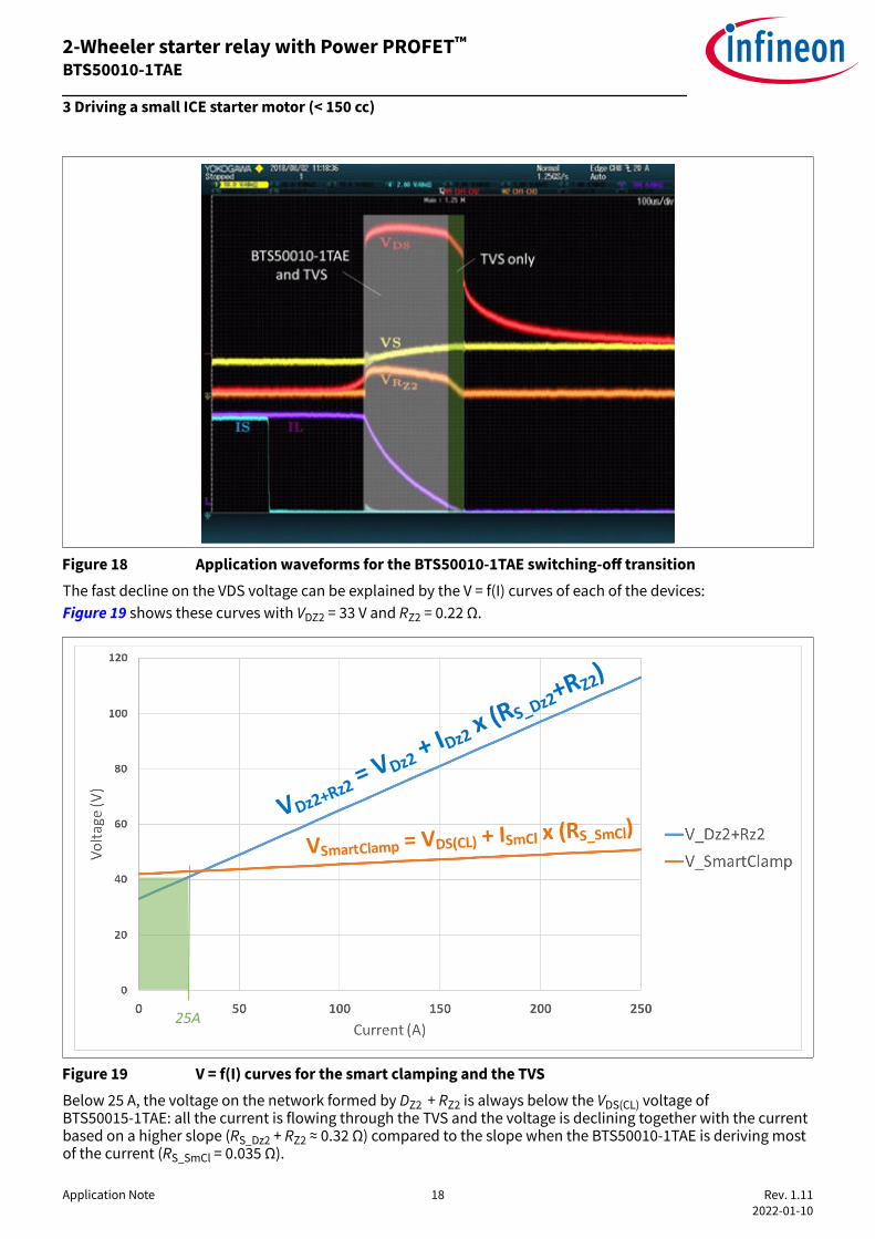
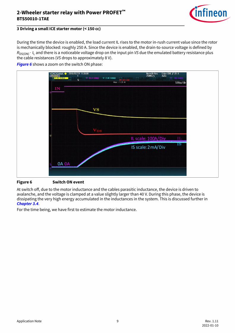
Figure 18 Application waveforms for the BTS50010-1TAE switching-off transitionThe fast decline on the VDS voltage can be explained by the V = f(I) curves of each of the devices:Figure 19 shows these curves with VDZ2 = 33 V and RZ2 = 0.22 Ω.
VDz2+Rz2 = VDz2 +
IDz2 x (RS_Dz2+RZ2)
VSmartClamp = VDS(CL) + ISmCl x (RS_SmCl)
25A
Figure 19 V = f(I) curves for the smart clamping and the TVSBelow 25 A, the voltage on the network formed by DZ2 + RZ2 is always below the VDS(CL) voltage ofBTS50015-1TAE: all the current is flowing through the TVS and the voltage is declining together with the currentbased on a higher slope (RS_Dz2 + RZ2 ≈ 0.32 Ω) compared to the slope when the BTS50010-1TAE is deriving mostof the current (RS_SmCl = 0.035 Ω).
2-Wheeler starter relay with Power PROFET™BTS50010-1TAE
3 Driving a small ICE starter motor (< 150 cc)
Application Note 18 Rev. 1.11 2022-01-10

It is also worth mentioning here that the two components together (BTS50010-1TAE + TVS) will bring a nice loaddump filtering feature on the motorcycle: indeed, in case of a load dump on the battery line, the voltage will belimited through these 2 components in series with the motor resistor.
Ideal zener diode
Series resistanceRS_SmCl
VDS(CL)
Ideal zener diode
Series resistanceRS_DZ2
VDz2
RZ2
TVS (DZ2) + RZ2
VS
OUTISmCl IDz2
MRMotor
Smart clamping Load dump clamping
Voltage on VS [V]
t
12V
Figure 20 Load dump clamping
3.5 Current sensingThe BTS50010-1TAE provides a current sense signal at pin IS.As long as no failure mode occurs (short circuit on OUT pin to ground / overcurrent / over temperature) and thecondition VIS ≤ VOUT – 5 V is fulfilled, a signal proportional to the load current is provided.The complete IS pin and diagnostic mechanism is described in section 5.4.3 of the device datasheet [1].A simplified diagram of the analogue current sense circuitry implemented in the BTS50010-1TAE is illustrated inthe Figure 21.
Sens
ed C
urre
nt: I
S
Load Current: IL
Range of values for IS in linear current sensing mode
Range of values for IS in fault flag mode
Sens
ed C
urre
nt: I
S
1kILIS
Range of load currents that can be differentiated from overload
Figure 21 Current sensing circuit in BTS50010-1TAEIdeally, the analog current sense diagnosis should reflect the load current without any additional error.However, in reality, the IS analogue current sense diagnosis do always have an inherent inaccuracy associated.This is shown in Figure 22 of the BTS50010-1TAE datasheet [1]:
2-Wheeler starter relay with Power PROFET™BTS50010-1TAE
3 Driving a small ICE starter motor (< 150 cc)
Application Note 19 Rev. 1.11 2022-01-10

1
𝑑𝐾𝑖𝑙𝑖𝑠, 𝑚𝑖𝑛
1
𝑑𝐾𝑖𝑙𝑖𝑠, 𝑚𝑎𝑥
≈ 55𝐴 ≈ 105𝐴
Figure 22 Sense current as a function of the load currentAs an example, when the IS pin delivers a current of 1.5 mA, the corresponding load current IL is between 55 Aand 105 A. To improve the accuracy of the current sense feature, a calibration is necessary. The application note"Power PROFET™ Improved SENSE Calibration and Benefits Guide" [2] details how to proceed and what level ofperformance can be achieved using a 1-point or a 2-point calibration procedure.Note: The sense feature is guaranteed to be linear until 150 A; since the load current can go up to 250 A withouttriggering the overcurrent protection, a saturation might be observed on the IS pin for a load current between150 A and 250 A.
2-Wheeler starter relay with Power PROFET™BTS50010-1TAE
3 Driving a small ICE starter motor (< 150 cc)
Application Note 20 Rev. 1.11 2022-01-10
3.6 Undervoltage protectionMore than providing a one-to-one replacement for the traditional electromechanical relay, the Infineon PowerPROFET™ provides additional useful features for the application.One of them is the undervoltage protection.To test this feature, the same set up as the one described in Chapter 3.2 is used here. The bank of resistors isused to increase the emulated battery output impedance, so that VS drops below the undervoltage threshold(5 V typical).
Figure 23 Activation of BTS50010-1TAE without (left) and with (right) under voltage triggeringWhen the conditions to trigger an undervoltage are met, the sequence is as follows:1. BTS50010-1TAE is exposed to a VS voltage which drops below the undervoltage threshold (5 V typical)2. The internal power MOSFET is immediately switched OFF, which generates a demagnetization phase3. The IS pin reports a fault status and BTS50010-1TAE is latched in OFF modeTo exit the latched-OFF mode, a reset sequence has to be applied on the IN pin (IN low for t > tIN(RESETDELAY)).
2-Wheeler starter relay with Power PROFET™BTS50010-1TAE
3 Driving a small ICE starter motor (< 150 cc)
Application Note 21 Rev. 1.11 2022-01-10

3.7 Battery disconnectionThe BTS50010-1TAE datasheet [1] in section 5.3.2 describes the recommended circuit to protect the device incase of loss of battery.The target here is to help to size the recommended Transient voltage suppressor, since it is used to demagnetizethe starter motor.Figure 24 illustrates how the TVS helps to protect BTS50010-1TAE: in step 1, the battery is connected and thecurrent flows from the battery to the starter motor and then back to the battery through the ground/chassisconnection. Step 2 shows that when the battery connection is lost, the demagnetization current will entirelyflow through the BTS50010-1TAE driver, which is not designed to survive the very high energy stored in thestarter motor. Step 3 describes how adding a TVS ensures that all the demagnetization current is routed awayfrom BTS50010-1TAE, thus keeping it safe.
Protection/Diagnosis
BTS50010-1TAE
IN
GND OUT
VS
ISProtection/Diagnosis
BTS50010-1TAE
IN
GND OUT
VS
ISProtection/Diagnosis
BTS50010-1TAE
IN
GND OUT
VS
IS
M M M1 2 3
BAT
-+ BAT
-+ BAT
-+
Figure 24 Current flow when the battery connection is lostThe Figure 25 and Figure 26 show the test results in the lab; first with a short cut of the VS supply (10 µs) andthen with a permanent switch OFF. It can be seen on the zoom that the MOSFET is initially turned ON, butduring the supply loss, the MOSFET is turned OFF due to the under voltage protection described in Chapter 3.6.The smart clamping feature is then visible on the VDS curve (pulse of 35 V). Whatever the scenario, the MOSFETremains latched OFF at the end: a reset sequence has to be applied on the IN pin (IN low for t > tIN(RESETDELAY)) tounlatch it.
Figure 25 Short disconnection of the power supply line (10 µs)
2-Wheeler starter relay with Power PROFET™BTS50010-1TAE
3 Driving a small ICE starter motor (< 150 cc)
Application Note 22 Rev. 1.11 2022-01-10

Figure 26 Permanent disconnection of the power supply line
2-Wheeler starter relay with Power PROFET™BTS50010-1TAE
3 Driving a small ICE starter motor (< 150 cc)
Application Note 23 Rev. 1.11 2022-01-10

3.8 Reverse battery protectionAll the members of the Power PROFET™ family come with a reverse battery protection feature, which is targetedat protecting the PROFET™ itself.The power MOSFET comes with a body diode which will unfortunately allow the current to flow through theload during battery polarity reversal (reverse battery). The MOSFET is then jeopardized since the power lossesare much higher when the current flows through the body diode rather than through the MOSFET itself.The protection for the MOSFET here consists in switching it ON when the control circuitry detects a reversebattery connection. Indeed, the power losses in the diode are in the order of: PDiode ≈ 1 V x IMotor which would bePDiode ≈ 40 W if IMotor = 40 A while these losses are PMOS = RDS(ON) x IMotor
2 which would be PMOS ≈ 3.52 W for thesame IMotor = 40 A, with RDS(ON) = 2.2 mΩ which is the worst case RDS(ON) for BTS50010-1TAE when the junctiontemperature is 150°C and the device is in reverse mode (see parameter P_6.1.30 in the device datasheet [1]).
Protection/Diagnosis
BTS50010-1TAE
IN
GND OUT
VS
IS
Protection/Diagnosis
BTS50010-1TAE
IN
GND OUT
VS
IS
BAT
Drawing flipped vertically for easier reading
M
M
BAT
Figure 27 Reverse battery connection: regular drawing (left), vertically flipped drawing (right)This protection only applies to the MOSFET, not to the load itself. Indeed, the load is still exposed to the batteryvoltage, in reverse polarity, so the starter motor will run backward which is not an issue since there is amechanical protection between the starter motor and the ICE for such a scenario.The most critical scenario in reverse battery is when the supply connection is temporary lost: there is somecurrent in the motor, which needs to be demagnetized. This scenario is very similar to the one described in Chapter 3.7. The main difference is the battery polarity and the resulting current direction. This is why theprotection device (TVS) is a bi-directional device, to be able to protect for the two possible current directions.Figure 28 illustrates how the TVS helps to protect BTS50010-1TAE: in step 1, the current flows from the startermotor to the battery through BTS50010-1TAE and then back to the motor through the ground/chassisconnection. Step 2 shows that when the battery connection is lost, the demagnetization current will entirelyflow through the BTS50010-1TAE driver, which is not designed to survive the very high energy stored in thestarter motor. Step 3 describes how the TVS is deriving all the demagnetization current from BTS50010-1TAE,thus keeping it safe.
2-Wheeler starter relay with Power PROFET™BTS50010-1TAE
3 Driving a small ICE starter motor (< 150 cc)
Application Note 24 Rev. 1.11 2022-01-10

Protection/Diagnosis
BTS50010-1TAE
IN
GND OUT
VS
ISProtection/Diagnosis
BTS50010-1TAE
IN
GND OUT
VS
ISProtection/Diagnosis
BTS50010-1TAE
IN
GND OUT
VS
IS
BAT
M M M1 2 3
+- BAT
+- BAT
+-
Figure 28 Current flow when the battery connection is lost in reverse battery polarityThe energy stored can be very high, if the loss of connection happens during the starter motor inrush/stallcurrent. In order to limit the stress on the TVS, a ground resistor is added (R_GND2, see Figure 29), whichdissipates part of the energy.
Protection/Diagnosis
BTS50010-1TAE
IN
GND OUT
VS
IS
MR_GND2R_GND1
BAT
+-
Figure 29 Additional resistors to limit the energy in the TVS
2-Wheeler starter relay with Power PROFET™BTS50010-1TAE
3 Driving a small ICE starter motor (< 150 cc)
Application Note 25 Rev. 1.11 2022-01-10

4 Practical considerations
4.1 ECU integration (space estimation)Due to regulations, there is a clear trend to move ICEs to clean Electrical Fuel Injection systems (EFI), whichrequire an ECU. An example for such an ECU is described on the Figure 30:
Figure 30 Block diagram of a small engine ECU based on Infineon componentsThis ECU can embed the BTS50010-1TAE.It is necessary then to use power connectors which will be able to sustain the very high inrush current of thestarter motor.Connecting cables for the power lines require special care: here also the high inrush current implies to use anappropriate section for the wiring.Figure 31 highlight (thick red) the wires from the positive terminal of the battery to BTS50010-1TAE VS pin andfrom BTS50010-1TAE OUT pin to starter motor positive terminal. These wires have to be sized in an appropriatemanner:
2-Wheeler starter relay with Power PROFET™BTS50010-1TAE
4 Practical considerations
Application Note 26 Rev. 1.11 2022-01-10

• The length of the two cables has to be limited such that in total the two wires represent less than 2 µH ofparasitic inductance (roughly < 2 meters). This is required to limit the energy during demagnetization of thewires parasitic inductance in case of a short circuit between the starter motor and ground.
• The wires section has to be sized properly to match two requirements:- Limit the inrush current to 250 A. Assuming a battery voltage of 12 V, the overall resistance has to be
minimum : 12/250 = 48 mΩ, to keep the current below 250 A. For a starter motor resistance of 29 mΩused in our tests, that means a wiring resistance of minimum : 48 - 29 = 19 mΩ.
- Limit the voltage drop seen by BTS50010-1TAE at start up so that the under voltage protection is nottriggered (otherwise the ignition process would immediately stop). Since the undervoltage threshold ismaximum 5.5 V, the maximum voltage drop in the wiring is : 12 - 5.5 = 6.5 V, which translates into awiring series resistance of maximum: [6.5/5.5] x RMot = [6.5/5.5] x 0.029 = 34 mΩ.
As a summary, for an application with VBAT = 12 V and RMot = 29 mΩ, the wiring series resistance has to be in therange 19 mΩ < RWiring < 34 mΩ.
M StarterMotor
ECU with BTS50010-1TAE
onboard
Power Supply
+ -
Figure 31 Power wiring diagram: the 4 red thick wires contribute to the total wiring resistance
2-Wheeler starter relay with Power PROFET™BTS50010-1TAE
4 Practical considerations
Application Note 27 Rev. 1.11 2022-01-10

4.2 DemoboardA demoboard is available for BTS50010-1TAE, which is designed in a very compact form factor(44.5 mm x 26.5 mm).
Figure 32 Demoboard picture
Figure 33 Schematic of the BTS50010-1TAE demoboardThe demoboard comes in two variants:1. BTS50010-1TAE BOARD: standard version, where D2 and R1 (highlighted in yellow) are not assembled2. BTS50010-1TAE DBTVS: D2 and R1 are assembled, to increase the energy capability during switch-OFF
(see Chapter 3.4 for more details on the rationale to have D2 and R1)Table 3 lists the bill of materials used on this demoboard:
2-Wheeler starter relay with Power PROFET™BTS50010-1TAE
4 Practical considerations
Application Note 28 Rev. 1.11 2022-01-10
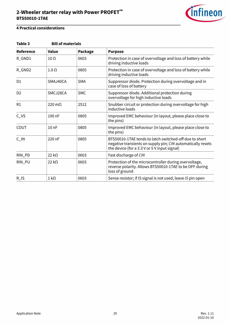
Table 3 Bill of materials
Reference Value Package PurposeR_GND1 10 Ω 0603 Protection in case of overvoltage and loss of battery while
driving inductive loads
R_GND2 1.0 Ω 0805 Protection in case of overvoltage and loss of battery whiledriving inductive loads
D1 SMAJ40CA SMA Suppressor diode. Protection during overvoltage and incase of loss of battery
D2 SMCJ28CA SMC Suppressor diode. Additional protection duringovervoltage for high inductive loads
R1 220 mΩ 2512 Snubber circuit or protection during overvoltage for highinductive loads
C_VS 100 nF 0805 Improved EMC behaviour (in layout, please place close tothe pins)
COUT 10 nF 0805 Improved EMC behaviour (in layout, please place close tothe pins)
C_IN 220 nF 0805 BTS50010-1TAE tends to latch switched-off due to shortnegative transients on supply pin; CIN automatically resetsthe device (for a 3.3 V or 5 V input signal)
RIN_PD 22 kΩ 0603 Fast discharge of CIN
RIN_PU 22 kΩ 0603 Protection of the microcontroller during overvoltage,reverse polarity. Allows BTS50010-1TAE to be OFF duringloss of ground
R_IS 1 kΩ 0603 Sense resistor; if IS signal is not used, leave IS pin open
2-Wheeler starter relay with Power PROFET™BTS50010-1TAE
4 Practical considerations
Application Note 29 Rev. 1.11 2022-01-10

5 Reference list1. BTS50010-1TAE datasheet2. Application Note on Improved SENSE Calibration and Benefits Guide
2-Wheeler starter relay with Power PROFET™BTS50010-1TAE
5 Reference list
Application Note 30 Rev. 1.11 2022-01-10

6 Revision history
Table 4 Revision history
Document version Date of release Description of changes
Rev. 1.00 2019-03-18 Initial application note
Rev. 1.10 2019-05-07 Changes restricted to text styles and minor typo corrections
2-Wheeler starter relay with Power PROFET™BTS50010-1TAE
6 Revision history
Application Note 31 Rev. 1.11 2022-01-10
Rev. 1.11 2022-01-10 Corrected typo in equation 2 on page 12

TrademarksAll referenced product or service names and trademarks are the property of their respective owners.
Edition 2019-05-07Published byInfineon Technologies AG81726 Munich, Germany © 2019 Infineon Technologies AGAll Rights Reserved. Do you have a question about anyaspect of this document?Email: [email protected] Document referenceIFX-yrg1553585918044
IMPORTANT NOTICEThe information contained in this application note isgiven as a hint for the implementation of the productonly and shall in no event be regarded as a descriptionor warranty of a certain functionality, condition orquality of the product. Before implementation of theproduct, the recipient of this application note mustverify any function and other technical informationgiven herein in the real application. InfineonTechnologies hereby disclaims any and all warrantiesand liabilities of any kind (including without limitationwarranties of non-infringement of intellectual propertyrights of any third party) with respect to any and allinformation given in this application note.
The data contained in this document is exclusivelyintended for technically trained staff. It is theresponsibility of customer’s technical departments toevaluate the suitability of the product for the intendedapplication and the completeness of the productinformation given in this document with respect to suchapplication.
WARNINGSDue to technical requirements products may containdangerous substances. For information on the typesin question please contact your nearest InfineonTechnologies office.Except as otherwise explicitly approved by InfineonTechnologies in a written document signed byauthorized representatives of Infineon Technologies,Infineon Technologies’ products may not be used inany applications where a failure of the product orany consequences of the use thereof can reasonablybe expected to result in personal injury