Embed Size (px)
Citation preview
Professional
Turf Manager’s
Guide to
Effi cient Irrigation
Practices and
Equipment
Table of Contents
Introduction ..........................................................................................................................................1Irrigation and Turfgrass Culture ........................................................................................................................................................... 1
General Principles of Turfgrass Irrigation ............................................................................................................................................. 1
Portable Irrigation Systems ................................................................................................................................................................. 2
Traveling Irrigators ................................................................................................................................................................. 2
Quick Coupler Systems ............................................................................................................................................................ 2
Installed Irrigation Systems ................................................................................................................................................................. 3
Design ................................................................................................................................................................................... 3
Piping .................................................................................................................................................................................... 3
Sprinklers, Nozzles and Swing Joints ....................................................................................................................................... 4
Valves .................................................................................................................................................................................... 5
Controllers ............................................................................................................................................................................. 5
Wires ..................................................................................................................................................................................... 6
Backfl ow Prevention ............................................................................................................................................................... 6
Construction and Reconstruction .......................................................................................................................................................... 6
As-Built Drawings and Controller Charts ................................................................................................................................... 7
Renovation ......................................................................................................................................................................................... 7
Winterization of a Sprinkler System ..................................................................................................................................................... 8
Spring Start-up ................................................................................................................................................................................... 8
Inspection and Maintenance of Irrigation Systems ................................................................................................................................ 9
Distribution Uniformity (DU) Testing .................................................................................................................................................. 10
The Catchment Test ............................................................................................................................................................... 10
Performing the Catchment Test .............................................................................................................................................. 11
Scheduling Water Usage .................................................................................................................................................................... 12
Amount of Water Needed ...................................................................................................................................................... 13
Evapotranspiration Rate ................................................................................................................................................... 13
Crop Coeffi cient ............................................................................................................................................................... 13
Available Water Holding Capacity (AWHC) Depletion .............................................................................................................. 14
Precipitation Rate ................................................................................................................................................................. 14
Application Effi ciency ............................................................................................................................................................ 14
Calculating the Irrigation Run Time ....................................................................................................................................... 15
The information in this booklet was excerpted from Sportsfi elds: A Manual for Design, Construction and Maintenance, by James Pulhalla, Jeffrey Krans, PhD, and Michael Goatley, PhD. Ann Arbor Press, Ann Arbor, Michigan, 1998.
The Manual’s chapter on Irrigation was written by Donald J.Turner, professional education manager, Hunter Industries.
1
A SAFE GREEN FIELD IS
THE GOAL OF ANY TURF
MANAGER, AND PROPER
IRRIGATION IS ONE OF
THE KEY ELEMENTS IN
REACHING THAT GOAL.
INSTALLED AUTOMATIC
IRRIGATION SYSTEMS
ARE BY FAR THE MOST
EFFICIENT AND EFFECTIVE
METHOD TO PROMOTE
HEALTHY TURFGRASS.
Introduction Professional turf managers for parks, public
areas and sports fi elds are constantly concerned about how their fi elds look and whether or not they are safe. Playable green turf with minimal risks is the goal of any fi eld manager, and proper irrigation is one of the key elements in reaching that goal.
In this booklet, we will consider the role of irrigation in the Integrated Cultural Management of a turf site. As we review the subject of irrigation, it is important that we distinguish between “irrigation” as a general process and “installed irrigation systems” as one way to accomplish that process. A fi eld can be irrigated in a number of ways; an installed irrigation system is one. We will briefl y discuss some of the other irrigation methods in wide use in North America, but the bulk of our discussion will focus on installed irrigation systems, which are by far the most effi cient and effective in promoting healthy turfgrass.
Irrigation and Turfgrass Culture
Strong, healthy turf will hold up better under the stress of sporting and other events, and adequate irrigation is critical to promoting that healthy turfgrass culture. Proper irrigation ensures deep and healthy roots, and helps the turf recover quickly from the damage infl icted by competition and other activities. Poorly irrigated sports fi elds, for example, may fail to recover from any substantial damage, and may become unplayable before the end of a season.
A healthy, properly watered turf will have fewer weeds and insects, reducing the need for fertilizer and pesticide applications. These reduced applications mean lower maintenance costs. Healthy turfgrass culture can have other cost advantages as well, including reduced water usage. When all of the potential savings are tabulated, it becomes increasingly apparent that a properly designed, installed, and maintained irrigation system, combined with a well thought-out watering schedule, can both reduce operating costs and contribute to a healthy turf. Even more important, well-irrigated turf promotes public
safety because it is softer and more uniform. Greener, more visually appealing fi elds also enhance community spirit and team pride – both among the players and among the team that maintains the facility.
General Principles of Turfgrass Irrigation
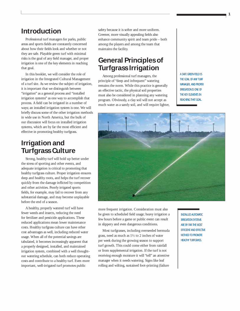
Among professional turf managers, the principle of “deep and infrequent” watering remains the norm. While this practice is generally an effective tactic, the physical soil properties must also be considered in planning any watering program. Obviously, a clay soil will not accept as much water as a sandy soil, and will require lighter,
more frequent irrigation. Consideration must also be given to scheduled fi eld usage; heavy irrigation a few hours before a game or public event can result in slippery and even dangerous conditions.
Most turfgrasses, including overseeded bermuda grass, need as much as 1½ to 2 inches of water per week during the growing season to support turf growth. This could come either from rainfall or from supplemental irrigation. If the turf is not receiving enough moisture it will “tell” an attentive manager when it needs watering. Signs like leaf rolling and wilting, sustained foot-printing (failure
2
HEALTHY,
PROPERLY WATERED
TURF WILL HAVE FEWER
WEEDS AND INSECTS,
REDUCING THE NEED
FOR FERTILIZER AND
PESTICIDE APPLICATIONS.
THE BEST TIME
TO IRRIGATE TURF IS IN THE
EARLY MORNING HOURS,
JUST PRIOR TO OR JUST
AFTER SUNRISE.
of the turf to spring back quickly after foot or vehicular traffi c), and a change in turf to a blue-green color are all characteristic of desiccation or excessive dryness.
The best time to irrigate turf is in the early morning hours, just prior to or just after sunrise. Early morning irrigation does not interfere with play in most situations, and serves to minimize the period of leaf surface wetness. Reducing the time the turf leaves stay wet is an effective way to reduce disease incidence. Early morning irrigation also tends to get more water into the soil for plant use, since evaporation rates at that time of day are minimal. Also, wind disruption of the irrigation pattern is of less concern in the early morning hours. Finally, early morning irrigation usually allows for adequate fi eld drying before a public event or athletic competition, so use can proceed without a slippery surface.
Portable Irrigation Systems
Portable irrigation systems are those which move around the fi eld, either transported by the staff or moving under their own power. Although these systems were once used on many fi elds, they cannot be considered as effi cient as installed systems.
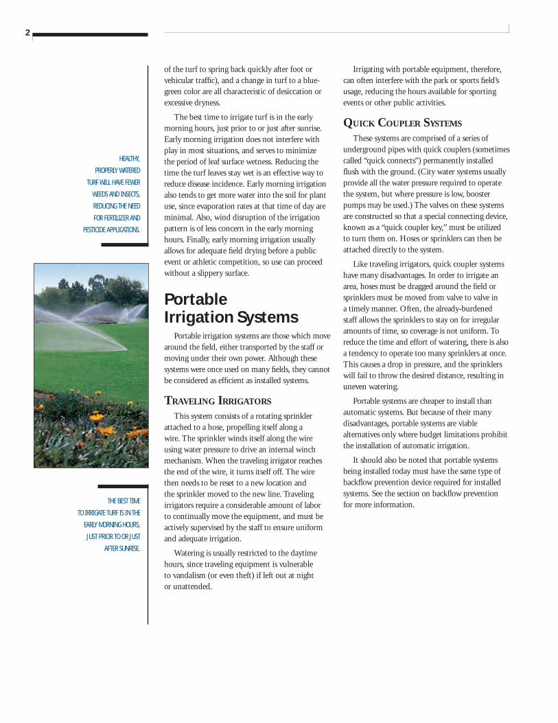
TRAVELING IRRIGATORS
This system consists of a rotating sprinkler attached to a hose, propelling itself along a wire. The sprinkler winds itself along the wire using water pressure to drive an internal winch mechanism. When the traveling irrigator reaches the end of the wire, it turns itself off. The wire then needs to be reset to a new location and the sprinkler moved to the new line. Traveling irrigators require a considerable amount of labor to continually move the equipment, and must be actively supervised by the staff to ensure uniform and adequate irrigation.
Watering is usually restricted to the daytime hours, since traveling equipment is vulnerable to vandalism (or even theft) if left out at night or unattended.
Irrigating with portable equipment, therefore, can often interfere with the park or sports fi eld’s usage, reducing the hours available for sporting events or other public activities.
QUICK COUPLER SYSTEMS
These systems are comprised of a series of underground pipes with quick couplers (sometimes called “quick connects”) permanently installed fl ush with the ground. (City water systems usually provide all the water pressure required to operate the system, but where pressure is low, booster pumps may be used.) The valves on these systems are constructed so that a special connecting device, known as a “quick coupler key,” must be utilized to turn them on. Hoses or sprinklers can then be attached directly to the system.
Like traveling irrigators, quick coupler systems have many disadvantages. In order to irrigate an area, hoses must be dragged around the fi eld or sprinklers must be moved from valve to valve in a timely manner. Often, the already-burdened staff allows the sprinklers to stay on for irregular amounts of time, so coverage is not uniform. To reduce the time and effort of watering, there is also a tendency to operate too many sprinklers at once. This causes a drop in pressure, and the sprinklers will fail to throw the desired distance, resulting in uneven watering.
Portable systems are cheaper to install than automatic systems. But because of their many disadvantages, portable systems are viable alternatives only where budget limitations prohibit the installation of automatic irrigation.
It should also be noted that portable systems being installed today must have the same type of backfl ow prevention device required for installed systems. See the section on backfl ow prevention for more information.
3
DESIGNING AN EFFECTIVE
SYSTEM REQUIRES
KNOWLEDGE OF PIPE
HYDRAULICS, ZONING
TECHNIQUES, HEAD
SPACING, WIRE SIZING,
AND IRRIGATION
EQUIPMENT.
SPECIFYING THE PROPER
PIPE SIZES HELPS TO
MAINTAIN THE CORRECT
WATER VELOCITY AND
MINIMIZES FRICTION
LOSSES THROUGHOUT
THE SYSTEM.
Installed Irrigation Systems
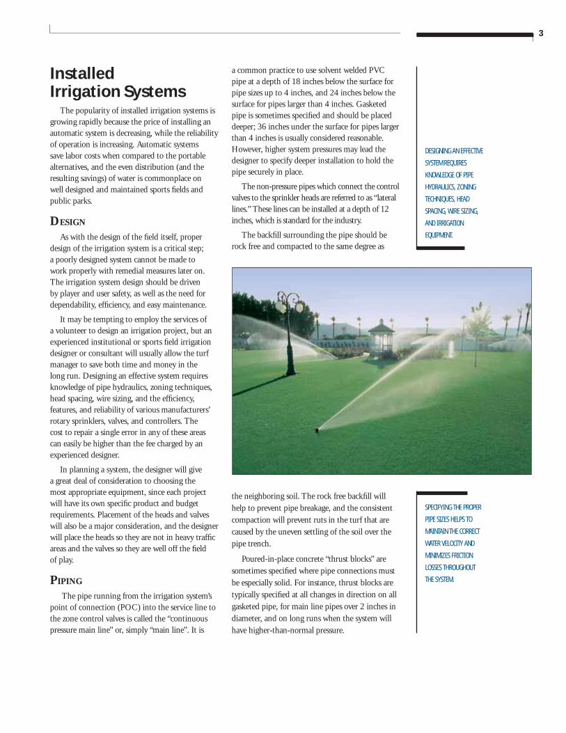
The popularity of installed irrigation systems is growing rapidly because the price of installing an automatic system is decreasing, while the reliability of operation is increasing. Automatic systems save labor costs when compared to the portable alternatives, and the even distribution (and the resulting savings) of water is commonplace on well designed and maintained sports fi elds and public parks.
DESIGN
As with the design of the fi eld itself, proper design of the irrigation system is a critical step; a poorly designed system cannot be made to work properly with remedial measures later on. The irrigation system design should be driven by player and user safety, as well as the need for dependability, effi ciency, and easy maintenance.
It may be tempting to employ the services of a volunteer to design an irrigation project, but an experienced institutional or sports fi eld irrigation designer or consultant will usually allow the turf manager to save both time and money in the long run. Designing an effective system requires knowledge of pipe hydraulics, zoning techniques, head spacing, wire sizing, and the effi ciency, features, and reliability of various manufacturers’ rotary sprinklers, valves, and controllers. The cost to repair a single error in any of these areas can easily be higher than the fee charged by an experienced designer.
In planning a system, the designer will give a great deal of consideration to choosing the most appropriate equipment, since each project will have its own specifi c product and budget requirements. Placement of the heads and valves will also be a major consideration, and the designer will place the heads so they are not in heavy traffi c areas and the valves so they are well off the fi eld of play.
PIPING
The pipe running from the irrigation system’s point of connection (POC) into the service line to the zone control valves is called the “continuous pressure main line” or, simply “main line”. It is
a common practice to use solvent welded PVC pipe at a depth of 18 inches below the surface for pipe sizes up to 4 inches, and 24 inches below the surface for pipes larger than 4 inches. Gasketed pipe is sometimes specifi ed and should be placed deeper; 36 inches under the surface for pipes larger than 4 inches is usually considered reasonable. However, higher system pressures may lead the designer to specify deeper installation to hold the pipe securely in place.
The non-pressure pipes which connect the control valves to the sprinkler heads are referred to as “lateral lines.” These lines can be installed at a depth of 12 inches, which is standard for the industry.
The backfi ll surrounding the pipe should be rock free and compacted to the same degree as
the neighboring soil. The rock free backfi ll will help to prevent pipe breakage, and the consistent compaction will prevent ruts in the turf that are caused by the uneven settling of the soil over the pipe trench.
Poured-in-place concrete “thrust blocks” are sometimes specifi ed where pipe connections must be especially solid. For instance, thrust blocks are typically specifi ed at all changes in direction on all gasketed pipe, for main line pipes over 2 inches in diameter, and on long runs when the system will have higher-than-normal pressure.
4
CARE SHOULD BE TAKEN
TO SELECT SPRINKLERS
WITH SMALL EXPOSED
SURFACE AREAS AND
PROTECTIVE RUBBER
COVERS TO MINIMIZE
SPORTS FIELD INJURY
AND LIABILITY.
PRECIPITATION RATE FOR
SPRINKLER SYSTEMS IS THE
RATE AT WHICH WATER IS
APPLIED OVER THE SURFACE
OF THE TURF. MATCHED
PRECIPITATION MEANS THE
ENTIRE FIELD IS RECEIVING
ABOUT THE SAME
AMOUNT OF WATER.
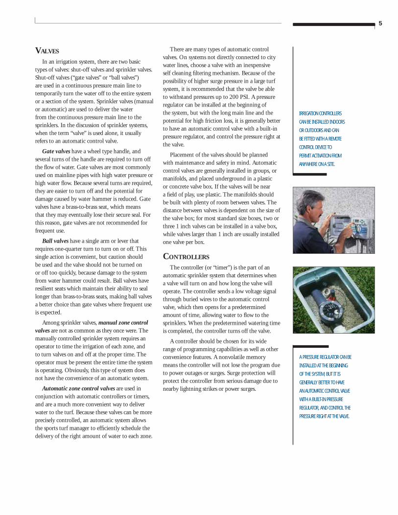
Chart 6-A Double Swing Joint Detail
Specifying the proper pipe sizes helps to maintain the correct water velocity and minimizes friction losses throughout the system. Water fl owing through pipes experiences considerable drag or friction from the pipe itself; when the velocity of the water increases, the pressure loss from friction increases. If the pipe used for the system is too small, the operating pressure will be much lower for the heads at the end of the zone than for the heads closest to the valve serving that zone. Irrigation designers agree that there should be no more than a 10% variation in pressure among all heads on a zone.
Because designers like to maintain about the same pressure from one zone to another, most institutional and sports fi eld irrigation system
designs will show a looped main line. The reduced pressure loss experienced when the water is fl owing from two directions in a looped main line helps to achieve a relatively balanced pressure throughout the main line at a reduced cost. The designer would have to size the pipe larger with a single connection main line than is necessary with the looped system. This smaller pipe size saves money while reducing the pressure loss to the furthest valve.
PVC pipe is also used as sleeves for the irrigation system’s pipes and wires where they pass under walkways, driveways, and roads. A good rule of thumb for sleeve sizing is two times the size of the pipe being sleeved.
SPRINKLERS, NOZZLES AND SWING JOINTS
A sprinkler head consists of three major components: the main body of the device, the nozzles through which water fl ows out of the body, and the swing joint at the bottom of the body which maintains the sprinkler’s connection to the lateral lines.
Sprinkler heads have been gradually downsized over the years, primarily for safety purposes. Newer heads have a small surface diameter and a protective thick rubber cover which makes them a very safe alternative to the older-style sprinklers. Additionally, many of the newer heads have a strong spring for positive retraction so the head will not endanger the public by staying in the up position after the watering is completed. Many of today’s safer heads also have a heavy-duty body cap to stand up to the large equipment now being used in routine maintenance.
Designers also like to choose a rotary sprinkler with a large nozzle selection. The nozzle is chosen to fi ne-tune the fl ow of water out of the system. The experienced irrigation system designer will use correct nozzle sizes to obtain “matched precipitation.” (The precipitation rate for sprinkler systems is the rate, expressed in inches per hour, at which water is applied over the surface of the turf. “Matched precipitation” means the entire fi eld is receiving about the same amount of water.)
Swing joints can be fabricated on-site by the installers of the system, or can be manufactured parts provided by the supplier. A three-elbow double swing joint will perform effi ciently if fabricated correctly. Manufactured double swing joints with O-Ring seals cut down on installation time and are often more dependable. Correctly installed, a double-swing joint provides fl exibility and resists breakage when large mowers or other heavy equipment rolls over the sprinkler.
5
IRRIGATION CONTROLLERS
CAN BE INSTALLED INDOORS
OR OUTDOORS AND CAN
BE FITTED WITH A REMOTE
CONTROL DEVICE TO
PERMIT ACTIVATION FROM
ANYWHERE ON A SITE.
A PRESSURE REGULATOR CAN BE
INSTALLED AT THE BEGINNING
OF THE SYSTEM, BUT IT IS
GENERALLY BETTER TO HAVE
AN AUTOMATIC CONTROL VALVE
WITH A BUILT-IN PRESSURE
REGULATOR, AND CONTROL THE
PRESSURE RIGHT AT THE VALVE.
VALVES
In an irrigation system, there are two basic types of valves: shut-off valves and sprinkler valves. Shut-off valves (“gate valves” or “ball valves”) are used in a continuous pressure main line to temporarily turn the water off to the entire system or a section of the system. Sprinkler valves (manual or automatic) are used to deliver the water from the continuous pressure main line to the sprinklers. In the discussion of sprinkler systems, when the term “valve” is used alone, it usually refers to an automatic control valve.
Gate valves have a wheel type handle, and several turns of the handle are required to turn off the fl ow of water. Gate valves are most commonly used on mainline pipes with high water pressure or high water fl ow. Because several turns are required, they are easier to turn off and the potential for damage caused by water hammer is reduced. Gate valves have a brass-to-brass seat, which means that they may eventually lose their secure seal. For this reason, gate valves are not recommended for frequent use.
Ball valves have a single arm or lever that requires one-quarter turn to turn on or off. This single action is convenient, but caution should be used and the valve should not be turned on or off too quickly, because damage to the system from water hammer could result. Ball valves have resilient seats which maintain their ability to seal longer than brass-to-brass seats, making ball valves a better choice than gate valves where frequent use is expected.
Among sprinkler valves, manual zone control valves are not as common as they once were. The manually controlled sprinkler system requires an operator to time the irrigation of each zone, and to turn valves on and off at the proper time. The operator must be present the entire time the system is operating. Obviously, this type of system does not have the convenience of an automatic system.
Automatic zone control valves are used in conjunction with automatic controllers or timers, and are a much more convenient way to deliver water to the turf. Because these valves can be more precisely controlled, an automatic system allows the sports turf manager to effi ciently schedule the delivery of the right amount of water to each zone.
There are many types of automatic control valves. On systems not directly connected to city water lines, choose a valve with an inexpensive self cleaning fi ltering mechanism. Because of the possibility of higher surge pressure in a large turf system, it is recommended that the valve be able to withstand pressures up to 200 PSI. A pressure regulator can be installed at the beginning of the system, but with the long main line and the potential for high friction loss, it is generally better to have an automatic control valve with a built-in pressure regulator, and control the pressure right at the valve.
Placement of the valves should be planned with maintenance and safety in mind. Automatic control valves are generally installed in groups, or manifolds, and placed underground in a plastic or concrete valve box. If the valves will be near a fi eld of play, use plastic. The manifolds should be built with plenty of room between valves. The distance between valves is dependent on the size of the valve box; for most standard size boxes, two or three 1 inch valves can be installed in a valve box, while valves larger than 1 inch are usually installed one valve per box.
CONTROLLERS
The controller (or “timer”) is the part of an automatic sprinkler system that determines when a valve will turn on and how long the valve will operate. The controller sends a low voltage signal through buried wires to the automatic control valve, which then opens for a predetermined amount of time, allowing water to fl ow to the sprinklers. When the predetermined watering time is completed, the controller turns off the valve.
A controller should be chosen for its wide range of programming capabilities as well as other convenience features. A nonvolatile memory means the controller will not lose the program due to power outages or surges. Surge protection will protect the controller from serious damage due to nearby lightning strikes or power surges.
6
INSTALLERS
RECOMMEND THAT THE
WIRE BE BURIED IN THE SAME
TRENCH AS THE MAIN LINE,
TAPED TO THE UNDER SIDE OF
THE PIPE. THIS WILL HELP TO
PROTECT THE WIRE, AND MAKE
IT EASIER TO LOCATE.
IN ORDER TO PROTECT THE
POTABLE (DRINKING) WATER
SUPPLY FROM CONTAMINATION,
MOST STATES AND
MUNICIPALITIES REQUIRE THE
INSTALLATION OF BACKFLOW
PREVENTION DEVICES.
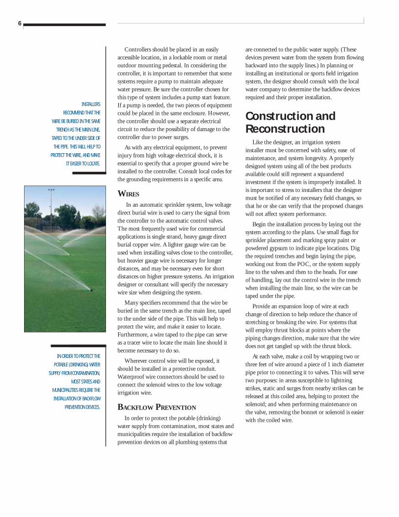
Controllers should be placed in an easily accessible location, in a lockable room or metal outdoor mounting pedestal. In considering the controller, it is important to remember that some systems require a pump to maintain adequate water pressure. Be sure the controller chosen for this type of system includes a pump start feature. If a pump is needed, the two pieces of equipment could be placed in the same enclosure. However, the controller should use a separate electrical circuit to reduce the possibility of damage to the controller due to power surges.
As with any electrical equipment, to prevent injury from high voltage electrical shock, it is essential to specify that a proper ground wire be installed to the controller. Consult local codes for the grounding requirements in a specifi c area.
WIRES
In an automatic sprinkler system, low voltage direct burial wire is used to carry the signal from the controller to the automatic control valves. The most frequently used wire for commercial applications is single strand, heavy gauge direct burial copper wire. A lighter gauge wire can be used when installing valves close to the controller, but heavier gauge wire is necessary for longer distances, and may be necessary even for short distances on higher pressure systems. An irrigation designer or consultant will specify the necessary wire size when designing the system.
Many specifi ers recommend that the wire be buried in the same trench as the main line, taped to the under side of the pipe. This will help to protect the wire, and make it easier to locate. Furthermore, a wire taped to the pipe can serve as a tracer wire to locate the main line should it become necessary to do so.
Wherever control wire will be exposed, it should be installed in a protective conduit. Waterproof wire connectors should be used to connect the solenoid wires to the low voltage irrigation wire.
BACKFLOW PREVENTION
In order to protect the potable (drinking) water supply from contamination, most states and municipalities require the installation of backfl ow prevention devices on all plumbing systems that
are connected to the public water supply. (These devices prevent water from the system from fl owing backward into the supply lines.) In planning or installing an institutional or sports fi eld irrigation system, the designer should consult with the local water company to determine the backfl ow devices required and their proper installation.
Construction and Reconstruction
Like the designer, an irrigation system installer must be concerned with safety, ease of maintenance, and system longevity. A properly designed system using all of the best products available could still represent a squandered investment if the system is improperly installed. It is important to stress to installers that the designer must be notifi ed of any necessary fi eld changes, so that he or she can verify that the proposed changes will not affect system performance.
Begin the installation process by laying out the system according to the plans. Use small fl ags for sprinkler placement and marking spray paint or powdered gypsum to indicate pipe locations. Dig the required trenches and begin laying the pipe, working out from the POC, or the system supply line to the valves and then to the heads. For ease of handling, lay out the control wire in the trench when installing the main line, so the wire can be taped under the pipe.
Provide an expansion loop of wire at each change of direction to help reduce the chance of stretching or breaking the wire. For systems that will employ thrust blocks at points where the piping changes direction, make sure that the wire does not get tangled up with the thrust block.
At each valve, make a coil by wrapping two or three feet of wire around a piece of 1 inch diameter pipe prior to connecting it to valves. This will serve two purposes: in areas susceptible to lightning strikes, static and surges from nearby strikes can be released at this coiled area, helping to protect the solenoid; and when performing maintenance on the valve, removing the bonnet or solenoid is easier with the coiled wire.
7
WHEN INSTALLING THE
VALVES BOXES, LAY A
BRICK BASE UNDER THE
EDGES OF EACH BOX TO
REDUCE SETTLING. SET THE
BOX IN PLACE, THEN
INSTALL A 2 TO 4 INCH
LAYER OF GRAVEL IN THE
BOX UNDER THE VALVE TO
PROVIDE FOR DRAINAGE.
ACCURATE AS-BUILT
DRAWINGS ARE VERY
IMPORTANT; THEY ALLOW
THE MAINTENANCE STAFF
TO LOCATE A PIPE OR
WIRE WITHOUT HAVING
TO DIG UP LARGE AREAS
OF THE FIELD.
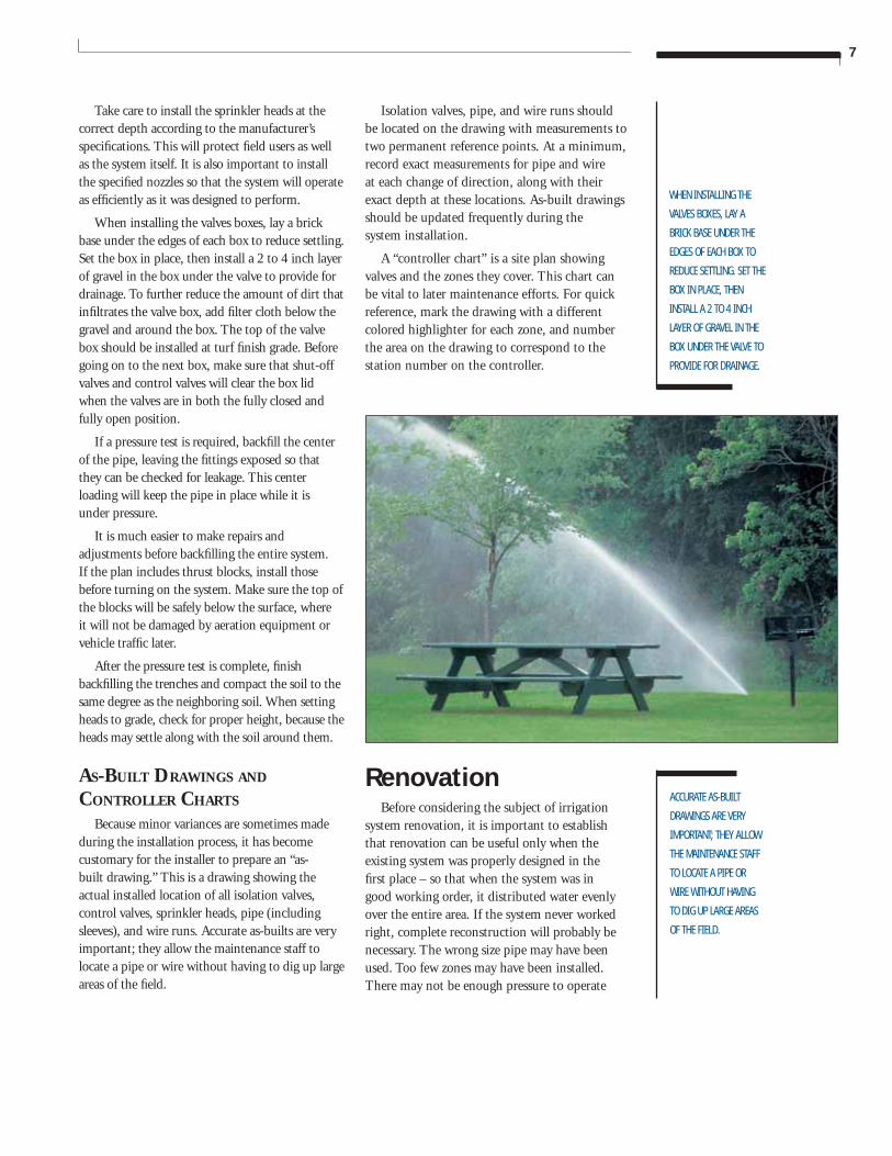
Take care to install the sprinkler heads at the correct depth according to the manufacturer’s specifi cations. This will protect fi eld users as well as the system itself. It is also important to install the specifi ed nozzles so that the system will operate as effi ciently as it was designed to perform.
When installing the valves boxes, lay a brick base under the edges of each box to reduce settling. Set the box in place, then install a 2 to 4 inch layer of gravel in the box under the valve to provide for drainage. To further reduce the amount of dirt that infi ltrates the valve box, add fi lter cloth below the gravel and around the box. The top of the valve box should be installed at turf fi nish grade. Before going on to the next box, make sure that shut-off valves and control valves will clear the box lid when the valves are in both the fully closed and fully open position.
If a pressure test is required, backfi ll the center of the pipe, leaving the fi ttings exposed so that they can be checked for leakage. This center loading will keep the pipe in place while it is under pressure.
It is much easier to make repairs and adjustments before backfi lling the entire system. If the plan includes thrust blocks, install those before turning on the system. Make sure the top of the blocks will be safely below the surface, where it will not be damaged by aeration equipment or vehicle traffi c later.
After the pressure test is complete, fi nish backfi lling the trenches and compact the soil to the same degree as the neighboring soil. When setting heads to grade, check for proper height, because the heads may settle along with the soil around them.
AS-BUILT DRAWINGS AND CONTROLLER CHARTS
Because minor variances are sometimes made during the installation process, it has become customary for the installer to prepare an “as-built drawing.” This is a drawing showing the actual installed location of all isolation valves, control valves, sprinkler heads, pipe (including sleeves), and wire runs. Accurate as-builts are very important; they allow the maintenance staff to locate a pipe or wire without having to dig up large areas of the fi eld.
Isolation valves, pipe, and wire runs should be located on the drawing with measurements to two permanent reference points. At a minimum, record exact measurements for pipe and wire at each change of direction, along with their exact depth at these locations. As-built drawings should be updated frequently during the system installation.
A “controller chart” is a site plan showing valves and the zones they cover. This chart can be vital to later maintenance efforts. For quick reference, mark the drawing with a different colored highlighter for each zone, and number the area on the drawing to correspond to the station number on the controller.
RenovationBefore considering the subject of irrigation
system renovation, it is important to establish that renovation can be useful only when the existing system was properly designed in the fi rst place – so that when the system was in good working order, it distributed water evenly over the entire area. If the system never worked right, complete reconstruction will probably be necessary. The wrong size pipe may have been used. Too few zones may have been installed. There may not be enough pressure to operate
8
RENOVATION OF A
PROPERLY INSTALLED
AND MAINTAINED
AUTOMATIC IRRIGATION
SYSTEM MAY BE
NECESSARY
EVERY SEVEN TO
TEN YEARS.
all the heads in a zone. (If low pressure is the only problem, it can be corrected simply by adding a booster pump.)
For our purposes, we will consider irrigation system renovation to consist mainly of replacing parts that have worn out due to normal usage.
Renovation of a properly installed and maintained automatic irrigation system may be necessary every seven to ten years. Sprinkler heads are the parts most commonly in need of replacement, since these items are in constant mechanical operation and are subjected to possible damage by the activity on the fi eld. Control valves can easily be rebuilt without removing the valve from the system. The valve’s diaphragm and solenoid are the only parts of the valve that move and may need replacing. (Pipe and wire rarely need to be replaced, since they have no moving parts.)
When replacing heads, dig down a few inches past the swing joint so the new head can be adjusted for height. When heads are being replaced, it may be wise to replace the swing joints while they are easily accessible.
Repair Couplings. Replacing valves, or repairing a broken pipe in systems fabricated from PVC pipe, is a lot easier with a “slip fi x”. A slip fi x is a PVC telescoping repair part, designed to replace a section of the existing pipe. Remove a section of the pipe near the existing valve (or the pipe that is broken), then remove the old valve and replace it with a new one. The slip fi x replaces the section of pipe that was removed. Retract the slip fi x and remove enough of the existing pipe to allow the slip fi x to fi t into the space. Extend the telescoping portion of the slip fi x over the existing pipe. Check alignment and then solvent weld (glue) the slip fi x in place.
When planning a renovation project, consider the possibility of improving the system. Older heads and valves can be replaced with the newer models that provide better performance. A good working manual system can also be upgraded to an automatic system by changing the manual control valves to automatic control valves. A controller (timer) must be installed and connected by wire to each valve to allow automatic operation.
Winterization of Sprinkler Systems
Winterization of the sprinkler system is the blowing out or draining of water to remove the possibility of it freezing within the system and breaking pipes or components. Winterization is performed in areas of the country which are subject to prolonged freezing.
If the irrigation system is drained by gravity, the process of winterization is simple. The system was installed with drains at the low points and when the water is turned off and the drains are opened, all water in the pipes drain out of the system. In these types of systems, it is critical to have an accurate “as-built” drawing in order to easily locate each drain valve.
More commonly, systems are winterized through a process of “blowing out” the pipes and components. With this method, there is less possibility of leaving water trapped in low areas of the piping. Replacing pipe which has cracked due to trapped and frozen water can be very costly.
A portable air compressor which can produce a high volume of air at lower pressures is necessary when blowing out an irrigation system. Systems consisting of pipe that is three inches or less in diameter can be blown out with a 125 CFM (cubic feet per minute) at 50 PSI air compressor. Systems with pipe that is four inches in diameter or larger may require a compressor capable of producing 250 CFM or more. In no case should the air pressure exceed 80 PSI.
It is highly recommended that blowing out a large turf irrigation system be performed by some one with experience in winterizing large systems. This is a dangerous procedure and the components can be damaged if the winterization is done incorrectly.
Spring Start-upSpring start-up after a winterization must be
done carefully as well. Open the last valve in the system, or the valve closest to the center of a looped main line. Slowly open the isolation valve to allow the water to seep into the system. It is important to be patient during this process so that the water entering the system will not fi ll the pipe too rapidly
9
WHEN PLANNING A
RENOVATION PROJECT,
CONSIDER THE POSSIBILITY
OF IMPROVING THE SYSTEM.
OLDER HEADS AND VALVES
CAN BE REPLACED WITH THE
NEWER MODELS THAT PROVIDE
BETTER PERFORMANCE.
and cause damage to the irrigation system due to water hammer.
When the main line is fully charged with water, open the next to last valve, leaving the previous valve open. When water is fl owing out of the second zone, turn off the fi rst zone and proceed to the next valve. Continue doing this with each valve until all valves in the system have been recharged.
Inspection and Maintenance of Irrigation Systems
As with every aspect of professional turf maintenance, the importance of regularly scheduled irrigation inspections cannot be overstated. Preventive maintenance saves money and improves the health and appearance of the turf. Small problems can be spotted and corrected long before they turn into big, costly problems. On the other hand, failure to perform regular maintenance can mean that a component may need to be replaced prematurely, or that the entire system may need a renovation before the end of its normal life cycle.
Once a week, look at the overall appearance of the turf, and test the system by manually running the controller through its cycle. These two quick checks will indicate whether the system is working correctly, or whether further testing is necessary.
When appraising the general appearance of the turf, look for stress areas that indicate poor irrigation coverage. The beginnings of “donuts,” dry areas around the heads, can mean there is a pressure problem, that someone has mis-adjusted the radius adjustment screw, or that the wrong nozzle has been installed.
Controllers. Before manually activating the controller, check to see if it is keeping the correct time of day. If not, the controller may have received a power surge, or a power outage may have disrupted its programming. No display, or a default display may suggest a blown fuse caused by faulty wiring, wire connectors, or valve solenoid.
Valves. As the controller activates and deactivates each valve, check for proper opening and closing. Slow or fast opening or closing valves can usually be adjusted with the valve’s fl ow control, but this can sometimes indicate a problem, such as high or low pressure or a torn diaphragm, and may suggest the need for further investigation.
Sprinklers. As the different zones come on, look carefully at the spray. If the water droplets seem too large, the system may be operating at low pressure. If the droplets are too small, or if there is excessive mist, the pressure may be too high. Many times, especially if the system previously worked fi ne, these conditions can be corrected by adjusting the fl ow control at the valve.
Rotary heads which are not rotating obviously require service. Many times a non-rotating sprinkler means a dirty fi lter, and can be disassembled and cleaned out quickly and easily. The staff should be instructed to resist the temptation to lubricate sticking heads. Although it may temporarily improve rotation, lubrication will eventually attract dirt and make the problem worse in the long run.
Make sure the heads are at the proper height, that they are adjusted correctly, and they are setting perpendicular to the turf.
Risers. During regular inspections, remember to look for signs of broken risers beneath the sprinklers. Sometimes these signs are obvious; a broken riser will unleash water to create huge geysers. Sometimes the signs are not so obvious; a cracked riser may allow water to boil up around the sprinkler but may not be readily visible. Watch for excessively wet or unusually dry areas.
Wiper Seals. While looking for broken risers and mis-adjustments, inspect the sprinkler for fl ow-by. A worn wiper seal can allow water to fl ow out of the sprinkler onto adjacent paved or turf areas, wasting water, damaging turf, and worst of all, causing unsafe conditions. (A wiper seal is located between the cap and the sprinkler’s riser.) A very small amount of water emitting past the wiper seal while the system is running is usually acceptable, but a leaking sprinkler head must be repaired or replaced.
It is very important that broken or poorly performing sprinkler heads be replaced as soon
10
DISTRIBUTION UNIFORMITY
(DU) IS CALCULATED BY
DIVIDING THE AMOUNT OF
WATER FALLING ON THE
LEAST WATERED PART OF A
ZONE BY THE AVERAGE
AMOUNT OF WATER FALLING
ON ALL THE ZONES.
IN ORDER TO
DETERMINE DISTRIBUTION
UNIFORMITY, A CATCHMENT
TEST OF THE TURFGRASS
AREA SHOULD BE
PERFORMED.
as possible. When a specifi c sprinkler is not operating correctly, the performance of all other heads on the zone is affected. For instance, water fl owing unchecked past a wiper seal will cause a loss in pressure to all heads on a zone. Because the pressure in that zone has dropped, the other sprinklers will not adequately irrigate the area.
If water is seeping past the wiper seal long after the system has turned off, the valve needs attention. A seeping valve could mean that debris is caught between the diaphragm and the valve seat, or that the diaphragm is beginning to tear. Replacing the diaphragm is a simple, fast, and inexpensive procedure. But if the torn diaphragm is not replaced, the slow seeping will waste a great deal of water, and could eventually
lead to a zone that is stuck on. If that happens at an inappropriate time, the turf could suffer severe damage.
Regularly scheduled irrigation checks will save time and money if they are performed on a consistent basis. A poorly maintained irrigation system will affect the health of the turfgrass culture and the appearance of the turf. A well maintained system will help to produce a healthy, visually appealing fi eld which holds up well under the stress of public use, sports and other events, and contributes to safe, competitive play.
Distribution Uniformity (DU) Testing
If the irrigation system is currently in operation and fi eld renovations are being considered, the system’s “distribution uniformity” (the evenness with which water is distributed over the fi eld) should be checked. Distribution uniformity (DU) is calculated by dividing the amount of water falling on the least watered part of a zone by the average amount of water falling on all the zones. An excellent DU percentage for rotors is 75% to 85%, while a good DU is 65% to 70%.
Once a system’s DU is known, an informed decision can be made about whether to repair or completely replace a system (or, if the DU falls within acceptable range, simply to leave the system alone).
THE CATCHMENT TEST
In order to determine distribution uniformity, a catchment test of the turfgrass area should be performed. This is a fairly easy test to conduct and often can uncover fi xable problems, even when a system appears to be functioning correctly.
The fi rst step in conducting a catchment test is to determine existing site conditions. Draw a sketch of the fi eld, with measurements, showing head locations. Write down all signifi cant information, including the type of heads used and their condition. Perform an actual head-by-head inspection to determine their condition, model number and the nozzle type. While walking the fi eld, look for signs of poor irrigation coverage, such as brown or bare spots.
Using a soil probe, take a few soil samples from different areas around the fi eld to determine soil type and root depth. This information will be helpful later in writing an irrigation schedule for the system.
Next, turn on one zone at a time and perform a visual inspection. Adjust the radius and the arc of water fl ow from each head, and align all heads to be perpendicular to the turf for maximum coverage. While adjusting the heads, watch for heavy leaking at the riser seal, and for failure to rotate properly.
11
Check Run Times
Example: The stations have a run time of 40 minutes per day, and the stations are programmed with two start times every day but Friday, Saturday, and Sunday.
Total Weekly Run Time 40 minutes x 2 start times per day x 4 days
or 40 x 2 x 4 = 320 minutes of run time.
Then, 320 ÷ 60 minutes in an hour = 5.3 hours of run time per week.
Answer
System 1 - A rotor with an approximate precipitation rate of .44 inches per hour would be putting down 2.3 inches of water per week (5.3 hours x .44 inches per hour or 5.3 x .44 = 2.3 inches per week).
System 2 - A rotor with an approximate precipitation rate of .85 inches per hour would be putting down 4.5 inches of water per week (5.3 hours x .85 inches per hour or 5.3 x .85 = 4.5 inches per week).
Chart 13-A - Station Run Times
CHECK THE AMOUNT OF
WATER BEING APPLIED TO THE
FIELD, ONE ZONE AT A TIME,
USING SMALL CATCH CANS.
ALL OF THE CANS SHOULD BE
THE SAME SIZE AND SHAPE,
AND SHOULD BE PLACED AT
ABOUT THE SAME HEIGHT
ABOVE THE TURF.
Clean any clogged nozzles, and be sure the fi lters are free of debris. Check for correct pressure, and for “donuts” of brown grass around the heads.
Using a rotor pitot tube and pressure gauge, check the pressure and pressure variation at the rotor’s nozzle. (Be sure to write down these pressure readings.) Variations of more than 20% from the highest pressure reading to the lowest within one zone may indicate a problem with the system, and the need for further inspection by an irrigation expert with a background in irrigation hydraulics. Frequently, pressure can be increased or decreased simply by adjusting the fl ow control on the valve for the zone.
Check the station start times and run times in the controller to see if there is a station with a longer run time than the others. This could indicate a problem with that particular valve or the rotors in that zone; the additional run time may be keeping the grass green and hiding the problem. Check the run times overall. Are dry spots causing longer run times? In most areas, turf will require about 1 1/2 to 2 inches of water per week in the hottest months. Calculate precipitation rates based on manufacturer’s published performance information and determine if the run times are close to where they should be.
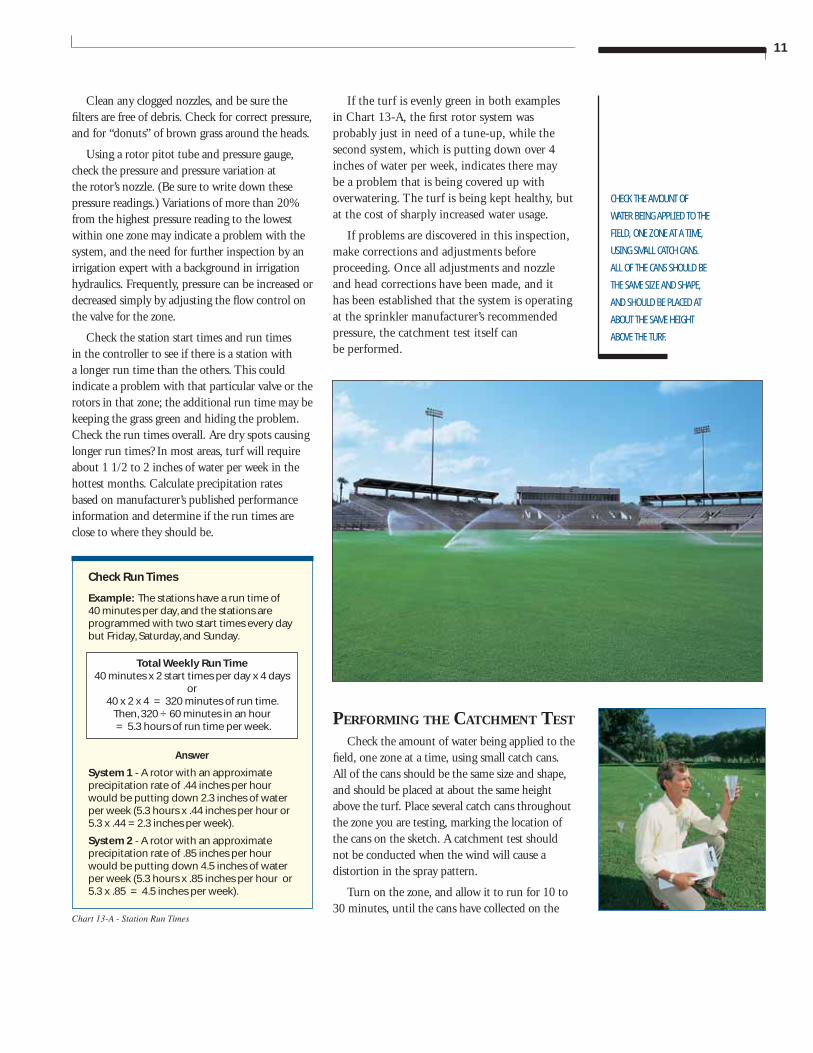
If the turf is evenly green in both examples in Chart 13-A, the fi rst rotor system was probably just in need of a tune-up, while the second system, which is putting down over 4 inches of water per week, indicates there may be a problem that is being covered up with overwatering. The turf is being kept healthy, but at the cost of sharply increased water usage.
If problems are discovered in this inspection, make corrections and adjustments before proceeding. Once all adjustments and nozzle and head corrections have been made, and it has been established that the system is operating at the sprinkler manufacturer’s recommended pressure, the catchment test itself can be performed.
PERFORMING THE CATCHMENT TEST Check the amount of water being applied to the
fi eld, one zone at a time, using small catch cans. All of the cans should be the same size and shape, and should be placed at about the same height above the turf. Place several catch cans throughout the zone you are testing, marking the location of the cans on the sketch. A catchment test should not be conducted when the wind will cause a distortion in the spray pattern.
Turn on the zone, and allow it to run for 10 to 30 minutes, until the cans have collected on the
12
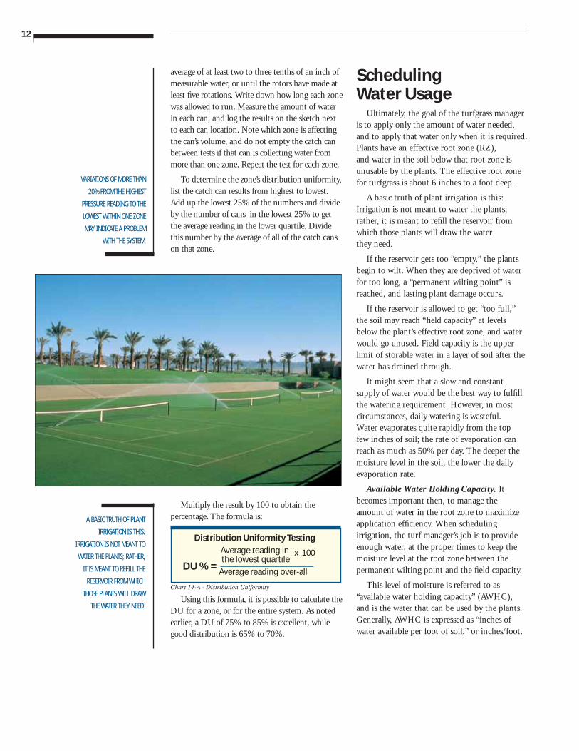
Using this formula, it is possible to calculate the DU for a zone, or for the entire system. As noted earlier, a DU of 75% to 85% is excellent, while good distribution is 65% to 70%.
Multiply the result by 100 to obtain the percentage. The formula is:
VARIATIONS OF MORE THAN
20% FROM THE HIGHEST
PRESSURE READING TO THE
LOWEST WITHIN ONE ZONE
MAY INDICATE A PROBLEM
WITH THE SYSTEM.
A BASIC TRUTH OF PLANT
IRRIGATION IS THIS:
IRRIGATION IS NOT MEANT TO
WATER THE PLANTS; RATHER,
IT IS MEANT TO REFILL THE
RESERVOIR FROM WHICH
THOSE PLANTS WILL DRAW
THE WATER THEY NEED.
Distribution Uniformity TestingAverage reading in the lowest quartile
Average reading over-all
Chart 14-A - Distribution Uniformity
x 100
DU % =
average of at least two to three tenths of an inch of measurable water, or until the rotors have made at least fi ve rotations. Write down how long each zone was allowed to run. Measure the amount of water in each can, and log the results on the sketch next to each can location. Note which zone is affecting the can’s volume, and do not empty the catch can between tests if that can is collecting water from more than one zone. Repeat the test for each zone.
To determine the zone’s distribution uniformity, list the catch can results from highest to lowest. Add up the lowest 25% of the numbers and divide by the number of cans in the lowest 25% to get the average reading in the lower quartile. Divide this number by the average of all of the catch cans on that zone.
Scheduling Water Usage
Ultimately, the goal of the turfgrass manager is to apply only the amount of water needed, and to apply that water only when it is required. Plants have an effective root zone (RZ), and water in the soil below that root zone is unusable by the plants. The effective root zone for turfgrass is about 6 inches to a foot deep.
A basic truth of plant irrigation is this: Irrigation is not meant to water the plants; rather, it is meant to refi ll the reservoir from which those plants will draw the water they need.
If the reservoir gets too “empty,” the plants begin to wilt. When they are deprived of water for too long, a “permanent wilting point” is reached, and lasting plant damage occurs.
If the reservoir is allowed to get “too full,” the soil may reach “fi eld capacity” at levels below the plant’s effective root zone, and water would go unused. Field capacity is the upper limit of storable water in a layer of soil after the water has drained through.
It might seem that a slow and constant supply of water would be the best way to fulfi ll the watering requirement. However, in most circumstances, daily watering is wasteful. Water evaporates quite rapidly from the top few inches of soil; the rate of evaporation can reach as much as 50% per day. The deeper the moisture level in the soil, the lower the daily evaporation rate.
Available Water Holding Capacity. It becomes important then, to manage the amount of water in the root zone to maximize application effi ciency. When scheduling irrigation, the turf manager’s job is to provide enough water, at the proper times to keep the moisture level at the root zone between the permanent wilting point and the fi eld capacity.
This level of moisture is referred to as “available water holding capacity” (AWHC), and is the water that can be used by the plants. Generally, AWHC is expressed as “inches of water available per foot of soil,” or inches/foot.
13
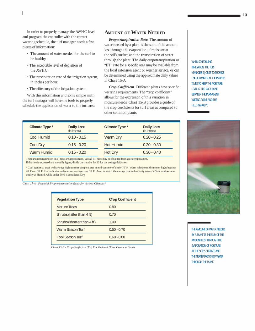
Climate Type * Daily Loss (in inches)
Cool Humid 0.10 - 0.15
Cool Dry 0.15 - 0.20
Warm Humid 0.15 - 0.20
WHEN SCHEDULING
IRRIGATION, THE TURF
MANAGER’S JOB IS TO PROVIDE
ENOUGH WATER AT THE PROPER
TIMES TO KEEP THE MOISTURE
LEVEL AT THE ROOT ZONE
BETWEEN THE PERMANENT
WILTING POINT AND THE
FIELD CAPACITY.
Vegetation Type Crop Coeffi cient
Mature Trees 0.80
Shrubs (taller than 4 ft) 0.70
Shrubs (shorter than 4 ft) 1.00
Warm Season Turf 0.50 - 0.70
Cool Season Turf 0.60 - 0.80
Chart 15-A - Potential Evapotranspiration Rates for Various Climates*
Chart 15-B - Crop Coeffi cient (KC) For Turf and Other Common Plants
These evapotranspiration (ET) rates are approximate. Actual ET rates may be obtained from an extension agent. If the rate is expressed as a monthly fi gure, divide the number by 30 for the average daily rate.
* Cool applies to areas with average high summer temperatures in mid-summer of under 70˚ F. Warm refers to mid-summer highs between 70˚ F and 90˚ F. Hot indicates mid-summer averages over 90˚ F. Areas in which the average relative humidity is over 50% in mid-summer qualify as Humid, while under 50% is considered Dry.
Climate Type * Daily Loss (in inches)
Warm Dry 0.20 - 0.25
Hot Humid 0.20 - 0.30
Hot Dry 0.30 - 0.40
THE AMOUNT OF WATER NEEDED
BY A PLANT IS THE SUM OF THE
AMOUNT LOST THROUGH THE
EVAPORATION OF MOISTURE
AT THE SOIL’S SURFACE AND
THE TRANSPIRATION OF WATER
THROUGH THE PLANT.
In order to properly manage the AWHC level and program the controller with the correct watering schedule, the turf manager needs a few pieces of information:
• The amount of water needed for the turf to be healthy.
• The acceptable level of depletion of the AWHC.
• The precipitation rate of the irrigation system, in inches per hour.
• The effi ciency of the irrigation system.
With this information and some simple math, the turf manager will have the tools to properly schedule the application of water to the turf area.
AMOUNT OF WATER NEEDED
Evapotranspiration Rate. The amount of water needed by a plant is the sum of the amount lost through the evaporation of moisture at the soil’s surface and the transpiration of water through the plant. The daily evapotranspiration or “ET” rate for a specifi c area may be available from the local extension agent or weather service, or can be determined using the approximate daily values in Chart 15-A.
Crop Coeffi cient. Different plants have specifi c watering requirements. The “crop coeffi cient” allows for the expression of this variation in moisture needs. Chart 15-B provides a guide of the crop coeffi cients for turf areas as compared to other common plants.
14
THE ACCEPTABLE LEVEL
OF DEPLETION, CALLED
“MANAGEMENT ALLOWABLE
DEPLETION” (MAD), CAN VARY
BY SOIL TYPE, COMPACTION,
ROOT DEPTH, AND THE STRESS
TOLERANCE OF THE PLANT.
APPLICATION EFFICIENCY (EA)
IS A MEASURE OF HOW MUCH
OF THE APPLIED WATER IS
AVAILABLE FOR USE IN THE
EFFECTIVE ROOT ZONE. IT
IS ALSO AN INDICATION OF
HOW WELL THE SYSTEM WAS
DESIGNED AND INSTALLED,
AND HOW WELL IT HAS BEEN
MAINTAINED.
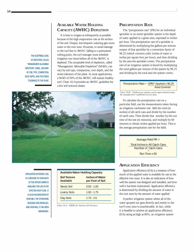
Available Water Holding Capacity
Soil Texture Inches of Water Available per Foot of Soil
Sandy Soil 0.50 - 1.00
Loamy Soils 1.00 - 1.75
Clay Soils 1.75 - 2.5
Chart 16-A - AWHC for Various Soil Textures
Chart 16-B - *Gallons per minute can be approximated using the manufacturer s̓ published nozzle data.
Precipitation Rate = GPM* Applied x 96.25 Area Covered
AVAILABLE WATER HOLDING CAPACITY (AWHC) DEPLETION
It is best to irrigate as infrequently as possible because of the high evaporation rate at the surface of the soil. Deeper, less frequent watering gets more water to the root zone. However, to avoid damage to the turf due to AWHC falling to a permanent wilting point, the turf manager must schedule irrigation run times before all of the AWHC is depleted. The acceptable level of depletion, called “Management Allowable Depletion” (MAD), can vary by soil type, compaction, root depth, and the stress tolerance of the plant. In most applications, a MAD of 50% of the AWHC will sustain healthy turf. Chart 16-A provides an AWHC guideline for a few soil textural classes.
PRECIPITATION RATE
The “precipitation rate” (PR) for an individual sprinkler or an entire sprinkler system is the depth of water applied in a given area, expressed in inches per hour. The precipitation rate of a sprinkler is determined by multiplying the gallons per minute output of that sprinkler by a conversion factor of 96.25 (which converts cubic inches of water to inches per square foot per hour), and then dividing by the area the sprinkler covers. The precipitation rate of an irrigation system is found by multiplying the total gallons per minute of the system by 96.25 and dividing by the total area the system covers.
To calculate the precipitation rate on a particular fi eld, use the measurements taken during an irrigation catchment test. Add the total (in inches) of all catch cans and divide by the number of catch cans. Then divide that number by the run time of the test (in minutes), and multiply by 60 minutes to obtain inches applied per hour. This is the average precipitation rate for the fi eld.
APPLICATION EFFICIENCY
Application effi ciency (EA) is a measure of how much of the applied water is available for use in the effective root zone. It is also an indication of how well the system was designed and installed, and how well it has been maintained. Application effi ciency is determined by dividing the amount of water in the root zone by the amount of water applied.
A perfect irrigation system where all of the water sprayed out goes directly and evenly to the turf ’s root zone is unachievable. In fact, while it is feasible to achieve an application effi ciency (EA) rating as high as 80%, an irrigation system
Average Field PR =
Total Inches in All Catch Cans Number of Catch Cans
÷ Run Time x 60
15
PROPER IRRIGATION
TECHNIQUE IS
IMPORTANT IN
DEVELOPING A
DEEP ROOT SYSTEM.
REPLENISHING THE
AWHC WITH FREQUENT
LIGHT WATERING IS THE
WORST POSSIBLE WAY TO
WATER TURF.
Run Time Examples
Example: A valve in your system is irrigating warm season turf which is growing in a sandy loam. The average precipitation rate is 0.49 inches/hour. The system is located in San Marcos, CA, where the daily moisture loss (ET) to be replenished is 0.20 inches. The system application effi ciency is approximately 65%.
Answer: Watering Frequency F = 1.0” x 0.75’ x 50% = 1.0 x 0.75 x 0.50 = 0.375 = 2.68 0.20 x 0.70 0.20 x 0.70 .14
The answer is a 2 or 3 day watering interval. The turf manager may decide to use a 3 day interval (water on day #1, wait day #2 and day #3, and then begin the watering interval again on the next day), and monitor the turf’s condition.
Run Time per Frequency RT = 60 x 3 x 0.20 x 0.70 = 180 x 0.14 = 25.2 = 79 0.49 x 65% 0.49 x 0.65 0.319
Irrigate 79 minutes each watering.
RZ Root Zone is the effective depth, in feet, of the roots (0.5’ to 1.0’ for turf).
ET Evaporation of soil surface water plus Transpiration of water through the plant. (Chart 15-A)
KC Crop coeffi cient is the specifi c
water requirement of the plant. (Chart 15-B)
AWHC Available Water Holding Capacity is the moisture level in the soil (expressed in inches per foot) which is above the plant’s permanent wilting point, and below the soil’s fi eld capacity. (Chart 16-A)
MAD Management Allowable Depletion of water from the AWHC. In most applications, a MAD of 50% will sustain healthy turf.
PR Precipitation Rate is the depth of water per unit of time. (Multiply the total gallons per minute of the system by 96.25 and divide by the total area the system covers.) (Chart 16-B)
EA Application Effi ciency is a measure of the overall effi ciency of the sprinkler system. (60% to 80%)
Chart 17-B - Run Time Formula
Chart 17-A - Scheduling Equation Values Chart 17-C - Run Time Examples
Frequency = AWHC x RZ x MAD
ET x KC
The amount of run time (RT) is calculated:
Run Time = 60 x F x ET x KC
PR x EA
Scheduling Equation Values
with an effi ciency rating of 70% is considered very good. Irrigation water can be lost through excessive evaporation (watering during the heat of the day), wind drift, incorrect adjustments, improper designs, high pressure, low pressure, runoff, percolation past the effective root zone, or through the use of the wrong size nozzles or other equipment.
There are several steps and calculations needed to determine irrigation system EA. While these calculations can be very accurate, because of the effects of wind, temperature, humidity, water pressure, soil type, and root depth, EA remains an informed estimate. For general purposes, a manager can expect to achieve an EA of 60% to 80%.
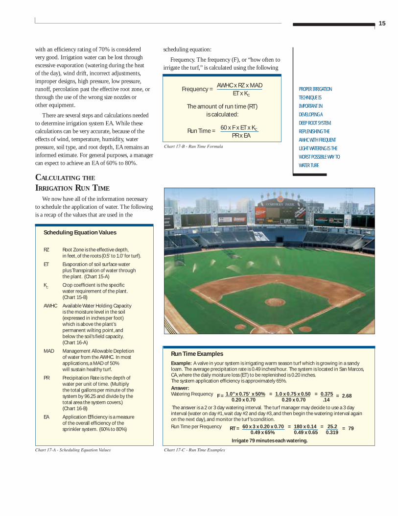
CALCULATING THE IRRIGATION RUN TIME
We now have all of the information necessary to schedule the application of water. The following is a recap of the values that are used in the
scheduling equation:
Frequency. The frequency (F), or “how often to irrigate the turf,” is calculated using the following
16
IF THE WATER IS
APPLIED FASTER THAN
THE INTAKE RATE, THE
WATER WILL RUN OFF
AND BE WASTED, AND
MAY CAUSE DAMAGE
TO THE TURF.
THE BEST METHOD
OF PRODUCING
TURF WITH A DEEP
ROOT SYSTEM IS
THROUGH CYCLICAL
WATERING AS
DESCRIBED IN THIS
BOOKLET.Chart 18-A - Soil Intake Rates for Various Soil Textures
Soil Texture Soil Intake Rate inches per hour
Sandy Soil 0.50 - 1.00
Loamy Soils 0.25 - 0.50
Clay Soils 0.10 - 0.25
formula:
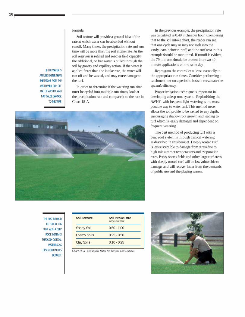
Soil texture will provide a general idea of the rate at which water can be absorbed without runoff. Many times, the precipitation rate and run time will be more than the soil intake rate. As the soil reservoir is refi lled and reaches fi eld capacity, the additional, or free water is pulled through the soil by gravity and capillary action. If the water is applied faster than the intake rate, the water will run off and be wasted, and may cause damage to the turf.
In order to determine if the watering run time must be cycled into multiple run times, look at the precipitation rate and compare it to the rate in Chart 18-A.
In the previous example, the precipitation rate was calculated as 0.49 inches per hour. Comparing that to the soil intake chart, the reader can see that one cycle may or may not soak into the sandy loam before runoff, and the turf area in this example should be monitored. If runoff is evident, the 79 minutes should be broken into two 40 minute applications on the same day.
Reprogram the controller at least seasonally to the appropriate run times. Consider performing a catchment test on a periodic basis to reevaluate the system’s effi ciency.
Proper irrigation technique is important in developing a deep root system. Replenishing the AWHC with frequent light watering is the worst possible way to water turf. This method never allows the soil profi le to be wetted to any depth, encouraging shallow root growth and leading to turf which is easily damaged and dependent on frequent watering.
The best method of producing turf with a deep root system is through cyclical watering as described in this booklet. Deeply rooted turf is less susceptible to damage from stress due to high midsummer temperatures and evaporation rates. Parks, sports fi elds and other large turf areas with deeply rooted turf will be less vulnerable to damage, and will recover faster from the demands of public use and the playing season.
17
Irrigation Training and Research Center. Landscape Water Management - Principles, Version 1.01. San Luis Obispo, California, California Polytechnic State University, 1992.
Keeson, Larry. The Complete Irrigation Workbook. Cleveland, Ohio, G.I.E. Inc., Publishers, 1995.
BIBLIOGRAPHY
Burt, Dr. Charles M.. Soil, Plant and Water Relationships. San Luis Obispo, California, California Polytechnic State University, 1992.
Hunter Industries Incorporated. Handbook of Technical Irrigation Information. San Marcos, California, Hunter Industries Incorporated, 1996.
Hunter Industries Incorporated. Irrigation Hydraulics. San Marcos, California, Hunter Industries Incorporated, 1997.
Hunter Industries Incorporated. Precipitation Rates and Sprinkler Irrigation. San Marcos, California, Hunter Industries Incorporated, 1996.
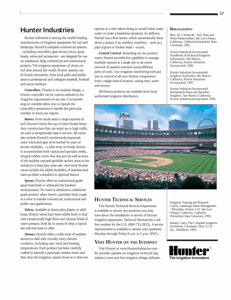
Hunter IndustriesHunter Industries is among the world’s leading
manufacturers of irrigation equipment for turf and landscape. Hunter’s complete commercial systems – including controllers, gear-driven rotors, spray heads, valves and accessories – are designed for use on residential, large commercial and institutional projects. The irrigation equipment of choice on turf sites around the world, Hunter systems can be found everywhere, from local parks and public areas to professional and collegiate baseball, football and soccer facilities.
Controllers. Thanks to its modular design, a Hunter controller can be custom-tailored to the irrigation requirements of any site. Convenient snap-in modules allow you to expand the controller’s operations to handle the particular number of zones you require.
Rotors. From small areas to large expanses of turf, Hunter’s entire line-up of rotors boasts heavy duty construction that can stand up to high traffi c, yet each is exceptionally easy to service. All rotors also include Hunter’s continuously-improved, water lubricated gear drive backed by years of proven reliability…a wide array of nozzle choices to accommodate both typical and specialty needs... integral rubber covers that stay put (as well as some of the smallest exposed sprinkler surface areas in the industry) to keep play areas safe. And most Hunter rotors include the added durability of stainless steel risers as either a standard or optional feature.
Sprays. Hunter offers an institutional-grade spray head built to withstand the harshest environments. No need to substitute a residential grade product when there’s a sprinkler built tough as a rotor to handle commercial, institutional and public area applications.
Valves. Available in heavy-duty plastic or solid brass, Hunter valves have been solidly built to deal with exceptionally high fl ows and extreme levels of water pressure, both far in excess of what a typical site will ever have to offer.
Sensors. Hunter offers a wide array of weather sensors to deal with virtually every climatic condition, including rain, wind and freezing temperatures. Each product has been carefully crafted to identify a particular weather event and then shut the irrigation system down so it does not
operate at a time where doing so would either waste water or create a hazardous situation. In addition, Hunter has a fl ow sensor, which automatically shuts down a system if an overfl ow condition – such as a pipe rupture or broken head – occurs.
Central Control. Rounding out the product roster, Hunter provides the capability to manage multiple systems at a single site or an entire network of systems scattered across different parts of town. Our irrigation monitoring tools put you in control of all your Hunter components from a single central location, saving time, water and money.
All Hunter products are available from local authorized irrigation distributors.
HUNTER TECHNICAL SERVICES The Hunter Technical Services Department
is available to answer any questions you may have about the installation or service of Hunter irrigation equipment. Technical Services has a toll free number for the U.S. (800-733-2823). A service representative is available to answer your questions Monday through Friday 8 a.m. to 5 p.m. (PST).
VISIT HUNTER ON THE INTERNET
Visit Hunter at www.HunterIndustries.com for periodic updates on irrigation technical tips, industry news and free irrigation design software.
Hunter Industries Incorporated 1940 Diamond Street, San Marcos, California, USA 92069 Telephone: (1) 760-744-5240 • Fax: (1) 760-744-7461 Technical Service: (1) 800-733-2823 www.HunterIndustries.com
P/N 700332LIT-263 3/04
Australia8 The Parade WestKent Town, S. Australia 5067Telephone: (61) 8-8363-3599Fax: (61) 8-8363-3687
EuropeBât. A2 - Europarc de Pichaury1330, rue Guillibert de la Lauzières13856 Aix-en-Provence Cedex 3, FranceTelephone: (33) 4-42-37-16-90Fax: (33) 4-42-39-89-71