Embed Size (px)
Citation preview
Professional Radio
GP300 Series
Basic Service Manual
68P64115B18C
Issue: Nov 2001

ii
Computer Software CopyrightsThe Motorola products described in this manual may include copyrighted Motorola computer programs stored in semiconductor memories or other media. Laws in the United States and other countries preserve for Motor-ola certain exclusive rights for copyrighted computer programs, including the exclusive right to copy or repro-duce in any form, the copyrighted computer program. Accordingly, any copyrighted Motorola computer programs contained in the Motorola products described in this manual may not be copied or reproduced in any manner without the express written permission of Motorola. Furthermore, the purchase of Motorola prod-ucts shall not be deemed to grant, either directly or by implication, estoppel or otherwise, any license under the copyrights, patents or patent applications of Motorola, except for the normal non-exclusive royalty-free license to use that arises by operation of law in the sale of a product.
iii
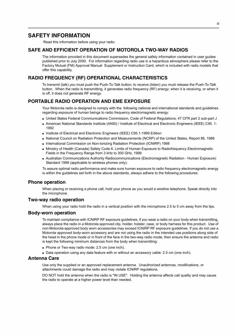
SAFETY INFORMATION Read this information before using your radio.
SAFE AND EFFICIENT OPERATION OF MOTOROLA TWO-WAY RADIOSThe information provided in this document supersedes the general safety information contained in user guides published prior to July 2000. For information regarding radio use in a hazardous atmosphere please refer to the Factory Mutual (FM) Approval Manual Supplement or Instruction Card, which is included with radio models that offer this capability.
RADIO FREQUENCY (RF) OPERATIONAL CHARACTERISTICSTo transmit (talk) you must push the Push-To-Talk button; to receive (listen) you must release the Push-To-Talk button. When the radio is transmitting, it generates radio frequency (RF) energy; when it is receiving, or when it is off, it does not generate RF energy.
PORTABLE RADIO OPERATION AND EME EXPOSUREYour Motorola radio is designed to comply with the following national and international standards and guidelines regarding exposure of human beings to radio frequency electromagnetic energy:� United States Federal Communications Commission, Code of Federal Regulations; 47 CFR part 2 sub-part J� American National Standards Institute (ANSI) / Institute of Electrical and Electronic Engineers (IEEE) C95. 1-
1992� Institute of Electrical and Electronic Engineers (IEEE) C95.1-1999 Edition� National Council on Radiation Protection and Measurements (NCRP) of the United States, Report 86, 1986� International Commission on Non-Ionizing Radiation Protection (ICNIRP) 1998� Ministry of Health (Canada) Safety Code 6. Limits of Human Exposure to Radiofrequency Electromagnetic
Fields in the Frequency Range from 3 kHz to 300 GHz, 1999� Australian Communications Authority Radiocommunications (Electromagnetic Radiation - Human Exposure)
Standard 1999 (applicable to wireless phones only):To assure optimal radio performance and make sure human exposure to radio frequency electromagnetic energy is within the guidelines set forth in the above standards, always adhere to the following procedures:
Phone operationWhen placing or receiving a phone call, hold your phone as you would a wireline telephone. Speak directly into the microphone.
Two-way radio operationWhen using your radio hold the radio in a vertical position with the microphone 2.5 to 5 cm away from the lips.
Body-worn operationTo maintain compliance with ICNIRP RF exposure guidelines, if you wear a radio on your body when transmitting, always place the radio in a Motorola approved clip, holder, holster, case, or body harness for this product. Use of non-Motorola-approved body worn accessories may exceed ICNIRP RF exposure guidelines. If you do not use a Motorola approved body-worn accessory and are not using the radio in the intended use positions along side of the head in the phone mode or in front of the face in the two-way radio mode, then ensure the antenna and radio is kept the following minimum distances from the body when transmitting:� Phone or Two-way radio mode: 2.5 cm (one inch).� Data operation using any data feature with or without an accessory cable: 2.5 cm (one inch).
Antenna CareUse only the supplied or an approved replacement antenna. Unauthorized antennas, modifications, or attachments could damage the radio and may violate ICNIRP regulations.DO NOT hold the antenna when the radio is "IN USE". Holding the antenna affects call quality and may cause the radio to operate at a higher power level than needed.
iv SAFETY INFORMATION
Approved AccessoriesFor a list of approved Motorola accessories please contact your dealer, or local Motorola representative.
ELECTROMAGNETIC INTERFERENCE/COMPATIBILITY
FACILITIESTo avoid electromagnetic interference and/or compatibility conflicts, turn off your radio in any facility where posted notices instruct you to do so. Hospitals or health care facilities may be using equipment that is sensitive to external RF energy.
AIRCRAFTWhen instructed to do so, turn off your radio when on board an aircraft. Any use of a radio must be in accordance with applicable regulations per airline crew instructions.
MEDICAL DEVICES
PacemakersThe Health Industry Manufacturers Association recommends that a minimum separation of 15 cms (6 inches) be maintained between a handheld wireless radio and a pacemaker.These recommendations are consistent with those of the U.S. Food and Drug Administration.Persons with pacemakers should:� ALWAYS keep the radio more than 15 cms from their pacemaker when the radio is turned ON.� not carry the radio in the breast pocket.� use the ear opposite the pacemaker to minimize the potential for interference.� turn the radio OFF immediately if you have any reason to suspect that interference is taking place.
Hearing AidsSome digital wireless radios may interfere with some hearing aids. In the event of such interference, you may want to consult your hearing aid manufacturer to discuss alternatives.
Other Medical DevicesIf you use any other personal medical device, consult the manufacturer of your device to determine if it is adequately shielded from RF energy. Your physician may be able to assist you in obtaining this information.
SAFETY AND GENERAL
Use While DrivingCheck the laws and regulations on the use of radios in the area where you drive. Always obey them.When using your radio while driving, please:� Give full attention to driving and to the road.� Use hands-free operation, if available.� Pull off the road and park before making or answering a call if driving conditions so require.
NOTE Nearly every electronic device is susceptible to electromagnetic interference (EMI) if inade-quately shielded, designed, or alternately configured for electromagnetic compatibility.
SAFETY INFORMATION v
OPERATIONAL WARNINGS
Vehicles with an air bag
Potentially explosive atmospheres
Blasting caps and areas
OPERATIONAL CAUTIONS
Damaged antennas
Batteries
WARNING: Do not place a portable radio in the area over an air bag or in the air bag deploy-ment area. Air bags inflate with great force. If a portable radio is placed in the air bag deploy-ment area and the air bag inflates, the radio may be propelled with great force and cause serious injury to occupants of vehicle.
WARNING: Turn off your radio prior to entering any area with a potentially explosive atmo-sphere, unless it is a radio type especially qualified for use in such areas as "Intrinsically Safe" (for example, Factory Mutual, CSA, UL or CENELEC Approved). Do not remove, install, or charge batteries in such areas. Sparks in a potentially explosive atmosphere can cause an explosion or fire resulting in bodily injury or even death.
NOTE The areas with potentially explosive atmospheres referred to above include fuelling areas such as below decks on boats, fuel or chemical transfer or storage facilities, areas where the air contains chemicals or particles, such as grain, dust or metal powders, and any other area where you would normally be advised to turn off your vehicle engine. Areas with potentially explosive atmospheres are often but not always posted.
WARNING: To avoid possible interference with blasting operations, turn off your radio when you are near electrical blasting caps. In a “blasting area” or in areas posted “turn off two-way radio”, obey all signs and instructions.
CAUTION: Do not use any portable radio that has a damaged antenna. If a damaged antenna comes into contact with your skin, a minor burn can result.
CAUTION: All batteries can cause property damage and/or bodily injury such as burns if a conductive material such as jewelry, keys or beaded chains touch exposed terminals. The conductive material may complete an electrical circuit (short circuit) and become quite hot. Exercise care in handling any charged battery, particularly when placing it inside a pocket, purse or other container with metal objects.
!
!
!
!
!

vi SAFETY INFORMATION
vii
Table of Contents
Chapter 1 INTRODUCTION
1.0 Scope of Manual.................................................................................................. 1-12.0 Warranty and Service Support ............................................................................ 1-1
2.1 Warranty Period and Return Instructions ....................................................... 1-12.2 After Warranty Period..................................................................................... 1-12.3 European Radio Support Centre (ERSC) ...................................................... 1-22.4 Piece Parts..................................................................................................... 1-22.5 Technical Support .......................................................................................... 1-3
3.0 Radio Model Information ..................................................................................... 1-4
Chapter 2 INTRINSICALLY SAFE RADIO INFORMATION
1.0 FMRC Approved Equipment................................................................................ 2-12.0 Repair of FMRC Approved Products ................................................................... 2-2
2.1 Repair............................................................................................................. 2-22.2 Relabelling ..................................................................................................... 2-22.3 Do Not Substitute Options or Accessories ..................................................... 2-3
Chapter 3 MAINTENANCE
1.0 Introduction.......................................................................................................... 3-12.0 Preventive Maintenance ...................................................................................... 3-1
2.1 Inspection....................................................................................................... 3-12.2 Cleaning Procedures...................................................................................... 3-1
3.0 Safe Handling of CMOS and LDMOS Devices.................................................... 3-24.0 Repair Procedures and Techniques — General.................................................. 3-35.0 Disassembling and Reassembling the Radio — General.................................... 3-36.0 Radio Disassembly — Detailed ........................................................................... 3-4
6.1 Front Cover from Chassis Disassembly......................................................... 3-46.2 Chassis Assembly Disassembly .................................................................... 3-66.3 Keypad, Display, and Keypad/Option Board Disassembly ............................ 3-76.4 Speaker, Microphone, and Universal Connector Flex Disassembly .............. 3-86.5 PTT Disassembly ........................................................................................... 3-96.6 Controller Board Disassembly (GP344/GP388)........................................... 3-106.7 Control Top Disassembly ............................................................................. 3-10
7.0 Radio Reassembly — Detailed.......................................................................... 3-107.1 Control Top Reassembly.............................................................................. 3-107.2 Controller Board Reassembly (GP344/GP388) ........................................... 3-107.3 PTT Reassembly.......................................................................................... 3-117.4 Speaker, Microphone, and Universal Connector Flex Reassembly............. 3-117.5 Keypad, Display, and Keypad Option Board Reassembly ........................... 3-11
viii
7.6 Chassis Assembly Reassembly....................................................................3-127.7 Chassis and Front Cover Reassembly .........................................................3-13
8.0 Option Board Installation....................................................................................3-149.0 Mechanical Views and Parts Lists......................................................................3-16
9.1 GP320/GP340 ..............................................................................................3-169.2 GP360/GP380 ..............................................................................................3-189.3 GP344...........................................................................................................3-209.4 GP388...........................................................................................................3-22
10.0 Service Aids .......................................................................................................3-2411.0 Test Equipment ..................................................................................................3-2512.0 Programming/Test Cable ...................................................................................3-26
Chapter 4 PERFORMANCE TESTING
1.0 Introduction ..........................................................................................................4-12.0 Receiver Performance Tests................................................................................4-13.0 Transmitter Performance Tests............................................................................4-2
Chapter 5 RADIO TUNING AND PROGRAMMING
1.0 Introduction ..........................................................................................................5-12.0 Global Radio Tuning Setup ..................................................................................5-1
2.1 Initial Test Equipment Setup...........................................................................5-23.0 CPS Programming Setup.....................................................................................5-2
Chapter 6 MODEL CHART AND TEST SPECIFICATION
1.0 Model Chart (UHF)...............................................................................................6-12.0 Model Chart (VHF) ...............................................................................................6-33.0 Model Chart (LB)..................................................................................................6-44.0 Model Chart (300R1)............................................................................................6-55.0 Specifications - Professional GP300 Series Radios ............................................6-6
5.1 GP320/340/360/380........................................................................................6-65.2 GP344/388......................................................................................................6-8
Chapter 7 POWER UP SELF-TEST
1.0 Error Codes..........................................................................................................7-1
Chapter 1
INTRODUCTION
1.0 Scope of Manual
This manual is intended for use by service technicians familiar with similar types of equipment. It contains service information required for the equipment described and is current as of the printing date. Changes which occur after the printing date may be incorporated by a complete Manual revision or alternatively as additions.
2.0 Warranty and Service Support
Motorola offers long term support for its products. This support includes full exchange and/or repair of the product during the warranty period, and service/ repair or spare parts support out of warranty. Any "return for exchange" or "return for repair" by an authorised Motorola Dealer must be accompanied by a Warranty Claim Form. Warranty Claim Forms are obtained by contacting an Authorised Motorola Dealer.
2.1 Warranty Period and Return Instructions
The terms and conditions of warranty are defined fully in the Motorola Dealer or Distributor or Reseller contract. These conditions may change from time to time and the following notes are for guidance purposes only.
In instances where the product is covered under a "return for replacement" or "return for repair" warranty, a check of the product should be performed prior to shipping the unit back to Motorola. This is to ensure that the product has been correctly programmed or has not been subjected to damage outside the terms of the warranty.
Prior to shipping any radio back to the appropriate Motorola warranty depot, please contact Customer Resources (Please see page 2 and page 3 in this Chapter). All returns must be accompanied by a Warranty Claim Form, available from your Customer Services representative. Products should be shipped back in the original packaging, or correctly packaged to ensure no damage occurs in transit.
2.2 After Warranty Period
After the Warranty period, Motorola continues to support its products in two ways.
1. Motorola's Radio Aftermarket and Accessory Division (AAD) offers a repair service to both end users and dealers at competitive prices.
2. AAD supplies individual parts and modules that can be purchased by dealers who are techni-cally capable of performing fault analysis and repair.
NOTE Before operating or testing these units, please read the Safety Information Section in thefront of this manual.
1-2 INTRODUCTION
2.3 European Radio Support Centre (ERSC)
The ERSC Customer Information Desk is available through the following service numbers:
Austria: 06 60 75 41 Italy: 16 78 77 387
Belgium: 08 00 72 471 Luxemburg: 08 00 23 27
Denmark: 80 01 55 72 Netherlands: 60 22 45 13
Finland: 08 00 11 49 10 Norway: 80 01 11 15
France: 05 90 30 90 Portugal: 05 05 49 35 70
Germany: 08 00 18 75 240 Spain: 90 09 84 902
Greece: 00 80 04 91 29 020 Sweden: 02 07 94 307
UK: 08 00 96 90 95 Switzerland: 1 55 30 82
Ireland: 18 00 55 50 21 Iceland: 80 08 147
Or dial Customer Care Centre:
Tel: +49 6128 70 2618
Please use these numbers for repair enquiries only
2.4 Piece Parts
Some replacement parts, spare parts, and/or product information can be ordered directly. If a complete Motorola part number is assigned to the part, it is available from Motorola Radio Aftermarket and Accessory Division (AAD). If no part number is assigned, the part is not normally available from Motorola. If the part number is appended with an asterisk, the part is serviceable by Motorola Depot only. If a parts list is not included, this generally means that no user-serviceable parts are available for that kit or assembly.
All enquiries should be directed to:
Motorola GmbHEuropean Parts Department65232 TaunussteinGermany.
Warranty and Service Support 1-3
2.5 Technical Support
Motorola Product Services is available to assist the dealer/distributors in resolving any malfunctions which may be encountered.
UK/Ireland - Richard RussellTelephone: +44 (0) 1256 488 082Fax: +44 01256 488 080Email: [email protected]
Central/East Europe - Siggy PunzenbergerTelephone: +49 (0) 6128 70 2342Fax: +49 (0) 6128 95 1096Email: [email protected]
Scandinavia Telephone: +46 8 735 9282Fax: +46 8 735 9280Email: [email protected]
Germany - Customer Connect TeamTelephone: +49 (0) 6128 70 2248Fax: +49 (0) 6128 95 1082Email: [email protected]
France - Lionel LhermitteTelephone: +33 1 6929 5722Fax: +33 1 6929 5904Email: [email protected]
Italy - Ugo GentileTelephone: +39 0 2822 0325Fax: +39 0 2822 0334Email: [email protected]
Africa & Middle East - Ralph SchubertTelephone: +33 (0)4 4230 5887Fax: +33 (0)4 4230 4784Email: [email protected]
1-4 INTRODUCTION
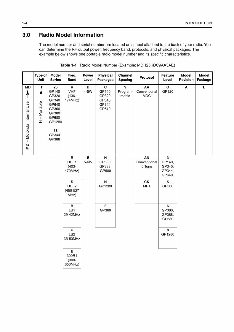
3.0 Radio Model Information
The model number and serial number are located on a label attached to the back of your radio. You can determine the RF output power, frequency band, protocols, and physical packages. The example below shows one portable radio model number and its specific characteristics.
Table 1-1 Radio Model Number (Example: MDH25KDC9AA3AE)
Type of Unit
Model Series
Freq. Band
Power Level
Physical Packages
Channel Spacing
ProtocolFeature Level
ModelRevision
Model Package
MD H 25GP140GP320GP340GP640GP360GP380GP680GP1280
38GP344GP388
KVHF(136-
174MHz)
D4-5W
CGP140, GP320,GP340,GP344,GP640.
9Program-
mable
AAConventional
MDC
OGP320
A E
RUHF1(403-
470MHz)
E5-6W
HGP380,GP388,GP680
ANConventional
5 Tone
3GP140,GP340,GP344,GP640.
SUHF2
(450-527 MHz)
NGP1280
CKMPT
5GP360
BLB1
29-42MHz
FGP360
6GP380,GP388,GP680
CLB2
35-50MHz
8GP1280
E300R1(300-
350MHz)
MD
= M
otor
ola
Inte
rnal
Use
H =
Por
tabl
e
Chapter 2
INTRINSICALLY SAFE RADIO INFORMATION
1.0 FMRC Approved EquipmentAnyone intending to use a radio in a location where hazardous concentrations of flammable material exist (hazardous atmosphere) is advised to become familiar with the subject of intrinsic safety and with the National Electric Code NFPA 70 (National Fire Protection Association) Article 500 (hazardous [classified] locations).
An Approval Guide, issued by Factory Mutual Research Corporation (FMRC), lists manufacturers and the products approved by FMRC for use in such locations. FMRC has also issued a voluntary approval standard for repair service (“Class Number 3605”).
FMRC Approval labels are attached to the radio to identify the unit as being FM Approved for specified hazardous atmospheres. This label specifies the hazardous Class/Division/Group along with the part number of the battery that must be used. Depending on the design of the portable unit, this FM label can be found on the back of the radio housing or the bottom of the radio housing.Their Approval mark is shown above.
Radios must ship from the Motorola manufacturing facility with the hazardous atmosphere capability and FM Approval labeling. Radios will not be “upgraded” to this capability and labeled in the field.
A modification changes the unit’s hardware from its original design configuration. Modifications can only be done by the original product manufacturer at one of its FMRC audited manufacturing facilities.
Unauthorized or incorrect modification of an FMRC Approved Product unit will negate the Approval rating of the product.
WARNING: Do not operate radio communications equipment in a hazardous atmosphere unless it is a type especially qualified (e.g. FMRC Approved) for such use. An explosion or fire may result.
WARNING: Do not operate the FMRC Approved Product in a hazardous atmosphere if it has been physically damaged (e.g. cracked housing). An explosion or fire may result.
WARNING: Do not replace or charge batteries in a hazardous atmosphere. Contact sparking may occur while installing or removing batteries and cause an explosion or fire.
WARNING: Do not replace or change accessories in a hazardous atmosphere. Contact sparking may occur while installing or removing accessories and cause an explosion or fire.
WARNING: Do not operate the FMRC Approved Product unit in a hazardous location with the accessory contacts exposed. Keep the connector cover in place when accessories are not used.
WARNING: Turn radio off before removing or installing a battery or accessory.
WARNING: Do not disassemble the FMRC Approved Product unit in any way that exposes the internal electrical circuits of the unit.
WARNING: Failure to use an FMRC Approved Product unit with an FMRC Approved battery or FMRC Approved accessories specifically approved for that product may result in the dangerously unsafe condition of an unapproved radio combination being used in a hazardous location.
FM
APPROVED
!
!
2-2 INTRINSICALLY SAFE RADIO INFORMATION
2.0 Repair of FMRC Approved Products
REPAIRS FOR MOTOROLA FMRC APPROVED PRODUCTS ARE THE RESPONSIBILITY OF THE USER
You should not repair or relabel any Motorola manufactured communication equipment bearing the FMRC Approval label (“FMRC Approved Product”) unless you are familiar with the current FMRC Approval standard for repairs and service (“Class Number 3605”).
You may want to consider using a repair facility that operates under 3605 repair service approval.
FMRC’s Approval Standard Class Number 3605 is subject to change at any time without notice to you, so you may want to obtain a current copy of 3605 from FMRC. Per the December, 1994 publication of 3605, some key definitions and service requirements are as follows:
2.1 Repair
A repair constitutes something done internally to the unit that would bring it back to its original condition Approved by FMRC. A repair should be done in an FMRC Approved facility.
Items not considered as repairs are those in which an action is performed on a unit which does not require the outer casing of the unit to be opened in a manner which exposes the internal electrical circuits of the unit. You do not have to be an FMRC Approved Repair Facility to perform these actions.
2.2 Relabelling
The repair facility shall have a method by which the replacement of FMRC Approval labels are controlled to ensure that any relabelling is limited to units that were originally shipped from the Manufacturer with an FM Approval label in place. FMRC Approval labels shall not be stocked by the repair facility. An FMRC Approval label shall be ordered from the original manufacturer as needed to repair a specific unit. Replacement labels may be obtained and applied by the repair facility providing satisfactory evidence that the unit being relabelled was originally an FMRC Approved unit.
Verification may include, but is not limited to: a unit with a damaged Approval label, a unit with a defective housing displaying an Approval label, or a customer invoice indicating the serial number of the unit and purchase of an FMRC Approved model.
WARNING: Incorrect repair or relabelling of any FMRC Approved Product unit could adversely affect the Approval rating of the unit.
WARNING: Use of a radio that is not intrinsically safe in a hazardous atmosphere could result in serious injury or death.
!
Repair of FMRC Approved Products 2-3
2.3 Do Not Substitute Options or Accessories
The Motorola communications equipment certified by Factory Mutual is tested as a system and consists of the FM Approved portable, FM Approved battery, and FM Approved accessories or options, or both. This Approved portable and battery combination must be strictly observed. There must be no substitution of items, even if the substitute has been previously Approved with a different Motorola communications equipment unit. Approved configurations are listed in the FM Approval guide published by FMRC, or in the product FM Supplement. This FM Supplement is shipped with FM Approved radio and battery combination from the manufacturer. The Approval guide, or the Approval standard Class Number 3605 document for repairs and service, can be ordered directly through Factory Mutual Research Corporation located in Norwood, Massachusetts.

2-4 INTRINSICALLY SAFE RADIO INFORMATION
Chapter 3
MAINTENANCE
1.0 Introduction
This chapter provides details about the following:
❏ Preventive maintenance (inspection and cleaning)❏ Safe handling of CMOS and LDMOS devices❏ Disassembly and reassembly of the radio❏ Repair procedures and techniques❏ Installation of Option Boards
2.0 Preventive Maintenance
The radios do not require a scheduled preventive maintenance program; however, periodic visual inspection and cleaning is recommended.
2.1 Inspection
Check that the external surfaces of the radio are clean, and that all external controls and switches are functional. It is not recommended to inspect the interior electronic circuitry.
2.2 Cleaning Procedures
The following procedures describe the recommended cleaning agents and the methods to be used when cleaning the external and internal surfaces of the radio. External surfaces include the front cover, housing assembly and battery case. These surfaces should be cleaned whenever a periodic visual inspection reveals the presence of smudges, grease, and/or grime.
The only recommended agent for cleaning the external radio surfaces is a 0.5% solution of a mild dishwashing detergent in water. The only factory recommended liquid for cleaning the printed circuit boards and their components is isopropyl alcohol (70% by volume).
Cleaning External Plastic Surfaces
Apply the 0.5% detergent-water solution sparingly with a stiff, non-metallic, short-bristled brush to work all loose dirt away from the radio. Use a soft, absorbent, lintless cloth or tissue to remove the solution and dry the radio. Make sure that no water remains entrapped near the connectors, cracks, or crevices.
NOTE Internal surfaces should be cleaned only when the radio is disassembled for service or repair.
CAUTION: The effects of certain chemicals and their vapors can have harmful results oncertain plastics. Avoid using aerosol sprays, tuner cleaners, and other chemicals.!
3-2 MAINTENANCE
Cleaning Internal Circuit Boards and Components
Isopropyl alcohol (70%) may be applied with a stiff, non-metallic, short-bristled brush to dislodge embedded or caked materials located in hard-to-reach areas. The brush stroke should direct the dislodged material out and away from the inside of the radio. Make sure that controls or tunable components are not soaked with alcohol. Do not use high-pressure air to hasten the drying process since this could cause the liquid to collect in unwanted places. After completing of the cleaning process, use a soft, absorbent, lintless cloth to dry the area. Do not brush or apply any isopropyl alcohol to the frame, front cover, or back cover.
3.0 Safe Handling of CMOS and LDMOS Devices
Complementary metal-oxide semiconductor (CMOS) devices are used in this family of radios, and are susceptible to damage by electrostatic or high voltage charges. Damage can be latent, resulting in failures occurring weeks or months later. Therefore, special precautions must be taken to prevent device damage during disassembly, troubleshooting, and repair.
Handling precautions are mandatory for CMOS circuits and are especially important in low humidity conditions. DO NOT attempt to disassemble the radio without first referring to the following CAUTION statement.
NOTE Always use a fresh supply of alcohol and a clean container to prevent contamination by dissolved material (from previous usage).
CAUTION: This radio contains static-sensitive devices. Do not open the radio unless you are properly grounded. Take the following precautions when working on this unit:
❏ Store and transport all CMOS devices in conductive material so that all exposed leads are shorted together. Do not insert CMOS devices into conventional plastic “snow” trays used for storage and transportation of other semiconductor devices.
❏ Ground the working surface of the service bench to protect the CMOS device. We recommend using the Motorola Static Protection Assembly (part number 0180386A82), which includes a wrist strap, two ground cords, a table mat, and a floor mat.
❏ Wear a conductive wrist strap in series with a 100k resistor to ground. (Replacement wrist straps that connect to the bench top covering are Motorola part number RSX4015.)
❏ Do not wear nylon clothing while handling CMOS devices.❏ Do not insert or remove CMOS devices with power applied. Check all power
supplies used for testing CMOS devices to be certain that there are no voltage transients present.
❏ When straightening CMOS pins, provide ground straps for the apparatus used.❏ When soldering, use a grounded soldering iron.❏ If at all possible, handle CMOS devices by the package and not by the leads. Prior to
touching the unit, touch an electrical ground to remove any static charge that you may have accumulated. The package and substrate may be electrically common. If so, the reaction of a discharge to the case would cause the same damage as touching the leads.
!
Repair Procedures and Techniques — General 3-3
4.0 Repair Procedures and Techniques — General
Parts Replacement and Substitution
When damaged parts are replaced, identical parts should be used. If the identical replacement part is not locally available, check the parts list for the proper Motorola part number and order the part from the nearest Motorola Communications parts centre listed in the “Piece Parts” section of this manual.
Rigid Circuit Boards
This family of radios uses bonded, multi-layer, printed circuit boards. Since the inner layers are not accessible, some special considerations are required when soldering and unsoldering components. The printed-through holes may interconnect multiple layers of the printed circuit. Therefore, exercise care to avoid pulling the plated circuit out of the hole.
When soldering near the 20-pin and 40-pin connectors:
❏ Avoid accidentally getting solder in the connector. ❏ Be careful not to form solder bridges between the connector pins. ❏ Examine your work closely for shorts due to solder bridges.
Flexible Circuits
The flexible circuits are made from a different material than the rigid boards, and require different soldering techniques. Excessive prolonged heat on a flexible circuit can damage the material. Therefore, avoid excessive heat and excessive bending.
For parts replacement, use the ST-1087 Temperature-Controlled Solder Station with a 600-700 degree tip, and use small diameter solder such as ST-633. The smaller size solder will melt faster and require less heat to be applied to the circuit.
To replace a component on a flexible circuit:
1. Grasp with seizers (hemostats) the edge of the flexible circuit near the part to be removed. 2. Pull gently.3. Apply the tip of the soldering iron to the component connections while pulling with the seizers.
5.0 Disassembling and Reassembling the Radio — General
Since these radios may be disassembled and reassembled with the use of only four (board to casting) screws, it is important to pay particular attention to the snaps and tabs, and how parts align with each other.
The following tools are required for disassembling the radio:❏ Small flat blade screwdriver❏ penknife-size screwdriver❏ TORX™ T6 screwdriver❏ Chassis opener (6680702Z01)
NOTE Do not attempt to puddle-out components. Prolonged application of heat may damage theflexible circuit.
3-4 MAINTENANCE
If a unit requires more complete testing or service than is customarily performed at the basic level, send this unit to a Motorola Authorized Service Centre. (See Chapter 1 for a list of authorized service centres.)
The following disassembly procedures should be performed only if necessary:
Chassis Assembly Disassembly (Paragraph 6.2)
Keypad, Display, and Keypad/Option Board Disassembly (Paragraph 6.3)
Speaker, Microphone, and Universal Connector Flex Disassembly (Paragraph 6.4)
PTT Disassembly (Paragraph 6.5)
Controller Board Disassembly -GP344/GP388 (Paragraph 6.6)
Control Top Disassembly (Paragraph 6.7)
6.0 Radio Disassembly — Detailed
6.1 Front Cover from Chassis Disassembly
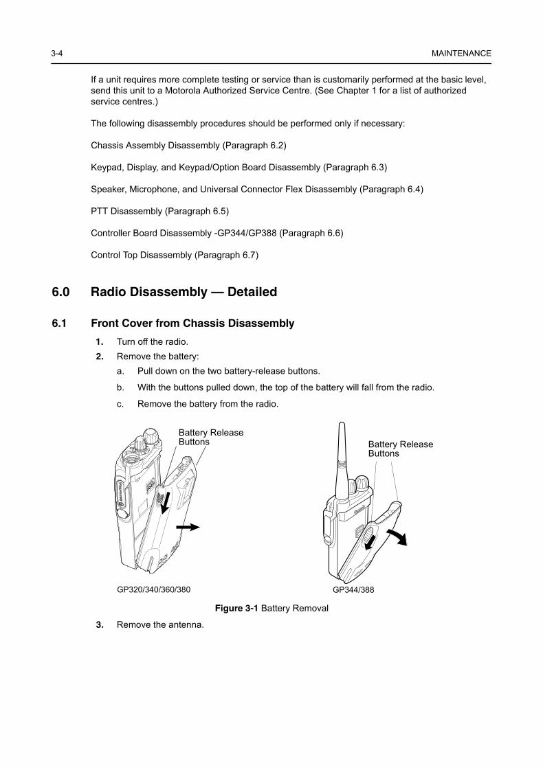
1. Turn off the radio.2. Remove the battery:
a. Pull down on the two battery-release buttons.
b. With the buttons pulled down, the top of the battery will fall from the radio.
c. Remove the battery from the radio.
3. Remove the antenna.
Figure 3-1 Battery Removal
Battery ReleaseButtons Battery Release
Buttons
GP320/340/360/380 GP344/388
Radio Disassembly — Detailed 3-5
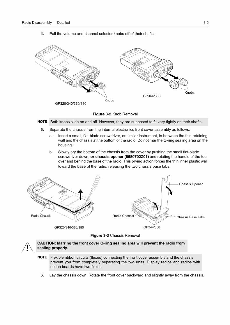
4. Pull the volume and channel selector knobs off of their shafts.
5. Separate the chassis from the internal electronics front cover assembly as follows:a. Insert a small, flat-blade screwdriver, or similar instrument, in between the thin retaining
wall and the chassis at the bottom of the radio. Do not mar the O-ring sealing area on the housing.
b. Slowly pry the bottom of the chassis from the cover by pushing the small flat-blade screwdriver down, or chassis opener (6680702Z01) and rotating the handle of the tool over and behind the base of the radio. This prying action forces the thin inner plastic wall toward the base of the radio, releasing the two chassis base tabs.
6. Lay the chassis down. Rotate the front cover backward and slightly away from the chassis.
Figure 3-2 Knob Removal
NOTE Both knobs slide on and off. However, they are supposed to fit very tightly on their shafts.
Figure 3-3 Chassis Removal
CAUTION: Marring the front cover O-ring sealing area will prevent the radio from sealing properly.
NOTE Flexible ribbon circuits (flexes) connecting the front cover assembly and the chassis prevent you from completely separating the two units. Display radios and radios withoption boards have two flexes.
KnobsGP320/340/360/380
GP344/388Knobs
Radio Chassis
Chassis Opener
Chassis Base TabsRadio Chassis
GP344/388GP320/340/360/380
!
3-6 MAINTENANCE
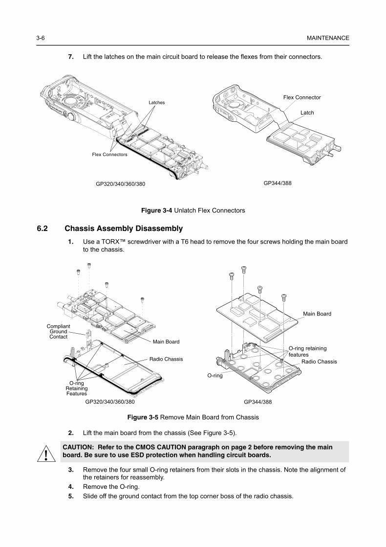
7. Lift the latches on the main circuit board to release the flexes from their connectors.
6.2 Chassis Assembly Disassembly
1. Use a TORX™ screwdriver with a T6 head to remove the four screws holding the main board to the chassis.
2. Lift the main board from the chassis (See Figure 3-5).
3. Remove the four small O-ring retainers from their slots in the chassis. Note the alignment of the retainers for reassembly.
4. Remove the O-ring.5. Slide off the ground contact from the top corner boss of the radio chassis.
Figure 3-4 Unlatch Flex Connectors
Figure 3-5 Remove Main Board from Chassis
CAUTION: Refer to the CMOS CAUTION paragraph on page 2 before removing the main board. Be sure to use ESD protection when handling circuit boards.
Latches
Flex Connectors
Flex Connector
Latch
GP320/340/360/380 GP344/388
Main Board
CompliantGroundContact
O-ringRetainingFeatures
Radio Chassis
Main Board
Radio Chassis
O-ring retainingfeatures
O-ring
GP320/340/360/380 GP344/388
!
Radio Disassembly — Detailed 3-7
6.3 Keypad, Display, and Keypad/Option Board Disassembly
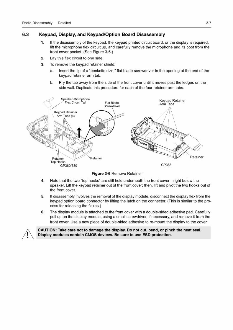
1. If the disassembly of the keypad, the keypad printed circuit board, or the display is required, lift the microphone flex circuit up, and carefully remove the microphone and its boot from the front cover pocket. (See Figure 3-6.)
2. Lay this flex circuit to one side.3. To remove the keypad retainer shield:
a. Insert the tip of a “penknife size,” flat blade screwdriver in the opening at the end of the keypad retainer arm tab.
b. Pry the tab away from the side of the front cover until it moves past the ledges on the side wall. Duplicate this procedure for each of the four retainer arm tabs.
4. Note that the two “top hooks” are still held underneath the front cover—right below the speaker. Lift the keypad retainer out of the front cover; then, lift and pivot the two hooks out of the front cover.
5. If disassembly involves the removal of the display module, disconnect the display flex from the keypad option board connector by lifting the latch on the connector. (This is similar to the pro-cess for releasing the flexes.)
6. The display module is attached to the front cover with a double-sided adhesive pad. Carefully pull up on the display module, using a small screwdriver, if necessary, and remove it from the front cover. Use a new piece of double-sided adhesive to re-mount the display to the cover.
Figure 3-6 Remove Retainer
CAUTION: Take care not to damage the display. Do not cut, bend, or pinch the heat seal. Display modules contain CMOS devices. Be sure to use ESD protection.
Keypad RetainerArm Tabs (4)
RetainerTop Hooks
Retainer
Flat BladeScrewdriver
Speaker-MicrophoneFlex Circuit Tail
GP360/380 GP388
Keypad RetainerArm Tabs
Retainer
!
3-8 MAINTENANCE
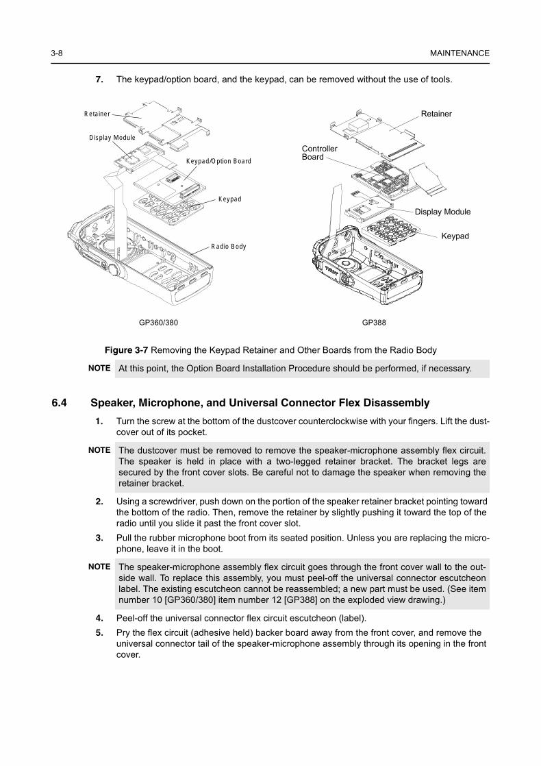
7. The keypad/option board, and the keypad, can be removed without the use of tools.
6.4 Speaker, Microphone, and Universal Connector Flex Disassembly
1. Turn the screw at the bottom of the dustcover counterclockwise with your fingers. Lift the dust-cover out of its pocket.
2. Using a screwdriver, push down on the portion of the speaker retainer bracket pointing toward the bottom of the radio. Then, remove the retainer by slightly pushing it toward the top of the radio until you slide it past the front cover slot.
3. Pull the rubber microphone boot from its seated position. Unless you are replacing the micro-phone, leave it in the boot.
4. Peel-off the universal connector flex circuit escutcheon (label).5. Pry the flex circuit (adhesive held) backer board away from the front cover, and remove the
universal connector tail of the speaker-microphone assembly through its opening in the front cover.
Figure 3-7 Removing the Keypad Retainer and Other Boards from the Radio Body
NOTE At this point, the Option Board Installation Procedure should be performed, if necessary.
NOTE The dustcover must be removed to remove the speaker-microphone assembly flex circuit.The speaker is held in place with a two-legged retainer bracket. The bracket legs aresecured by the front cover slots. Be careful not to damage the speaker when removing theretainer bracket.
NOTE The speaker-microphone assembly flex circuit goes through the front cover wall to the out-side wall. To replace this assembly, you must peel-off the universal connector escutcheonlabel. The existing escutcheon cannot be reassembled; a new part must be used. (See itemnumber 10 [GP360/380] item number 12 [GP388] on the exploded view drawing.)
Keypad/Option Board
Retainer
Display Module
Keypad
Radio Body
GP360/380 GP388
Retainer
ControllerBoard
Display Module
Keypad
Radio Disassembly — Detailed 3-9
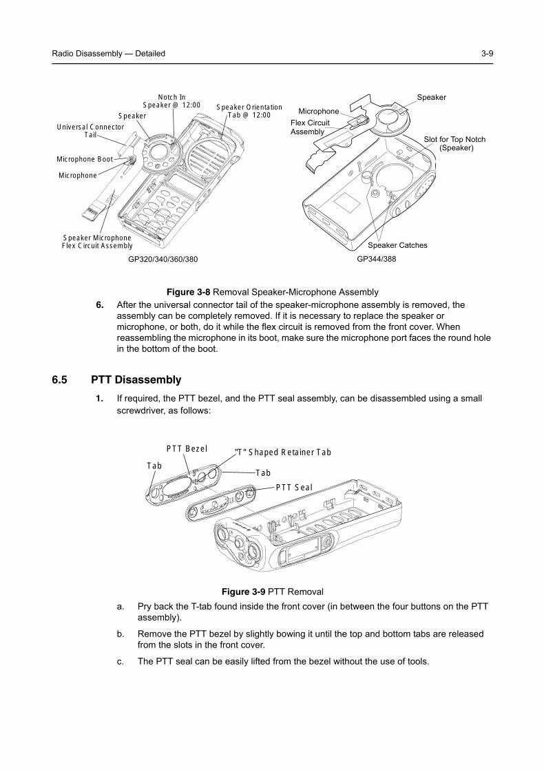
6. After the universal connector tail of the speaker-microphone assembly is removed, the assembly can be completely removed. If it is necessary to replace the speaker or microphone, or both, do it while the flex circuit is removed from the front cover. When reassembling the microphone in its boot, make sure the microphone port faces the round hole in the bottom of the boot.
6.5 PTT Disassembly
1. If required, the PTT bezel, and the PTT seal assembly, can be disassembled using a small screwdriver, as follows:
a. Pry back the T-tab found inside the front cover (in between the four buttons on the PTT assembly).
b. Remove the PTT bezel by slightly bowing it until the top and bottom tabs are released from the slots in the front cover.
c. The PTT seal can be easily lifted from the bezel without the use of tools.
Figure 3-8 Removal Speaker-Microphone Assembly
Figure 3-9 PTT Removal
Speaker
Notch InSpeaker @ 12:00 Speaker Orientation
Tab @ 12:00
Microphone Boot
Universal ConnectorTail
Microphone
Speaker MicrophoneFlex Circuit Assembly
Speaker
Flex CircuitAssembly
Microphone
Slot for Top Notch(Speaker)
Speaker Catches
GP320/340/360/380 GP344/388
Tab
PTT Bezel
Tab
"T" Shaped Retainer Tab
PTT Seal
3-10 MAINTENANCE
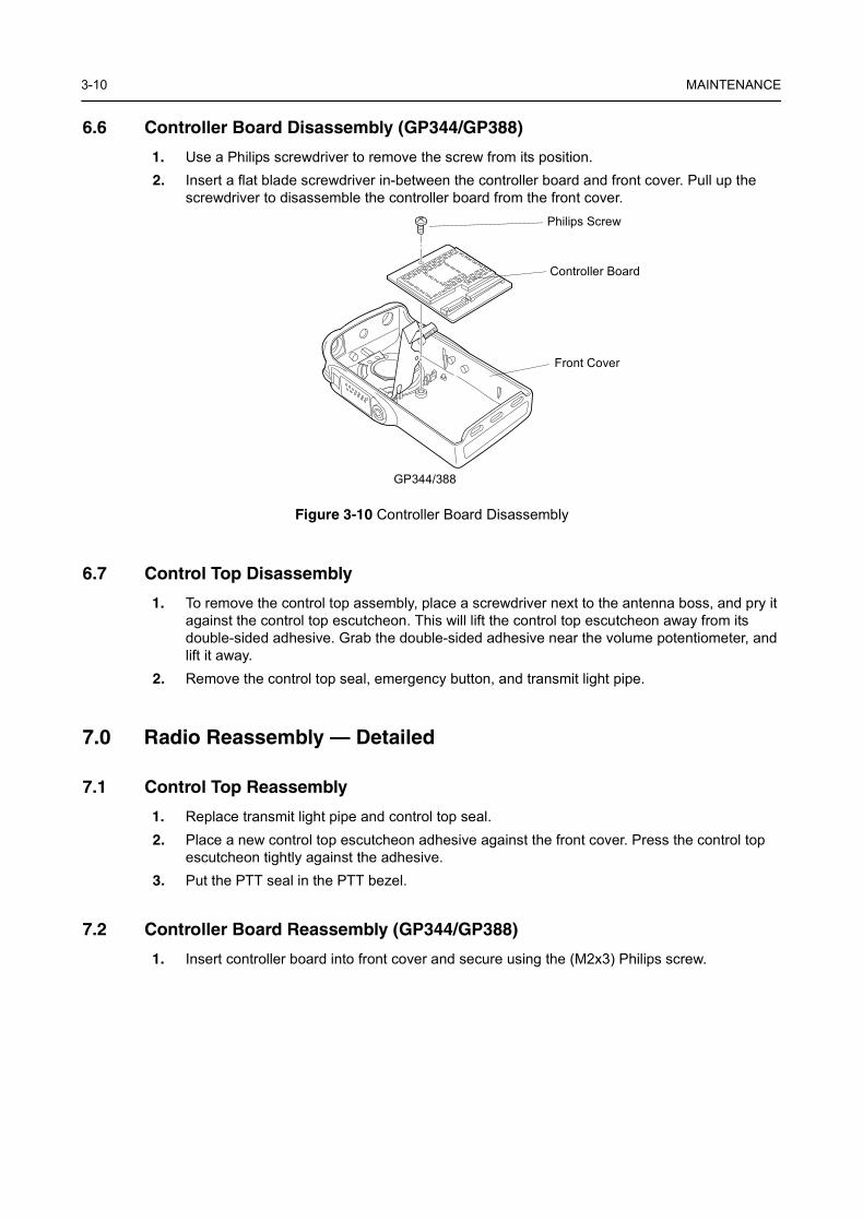
6.6 Controller Board Disassembly (GP344/GP388)
1. Use a Philips screwdriver to remove the screw from its position.2. Insert a flat blade screwdriver in-between the controller board and front cover. Pull up the
screwdriver to disassemble the controller board from the front cover.
Figure 3-10 Controller Board Disassembly
6.7 Control Top Disassembly
1. To remove the control top assembly, place a screwdriver next to the antenna boss, and pry it against the control top escutcheon. This will lift the control top escutcheon away from its double-sided adhesive. Grab the double-sided adhesive near the volume potentiometer, and lift it away.
2. Remove the control top seal, emergency button, and transmit light pipe.
7.0 Radio Reassembly — Detailed
7.1 Control Top Reassembly
1. Replace transmit light pipe and control top seal. 2. Place a new control top escutcheon adhesive against the front cover. Press the control top
escutcheon tightly against the adhesive.3. Put the PTT seal in the PTT bezel.
7.2 Controller Board Reassembly (GP344/GP388)
1. Insert controller board into front cover and secure using the (M2x3) Philips screw.
Philips Screw
Controller Board
Front Cover
GP344/388
Radio Reassembly — Detailed 3-11
7.3 PTT Reassembly
1. Place the bezel top tab in the top slot inside the front cover PTT opening. Slightly bow the bezel so that the bottom tab can fall inside the bottom slot.
2. Press the PTT assembly against the front cover opening.
7.4 Speaker, Microphone, and Universal Connector Flex Reassembly
1. Feed the universal connector tail of the speaker-microphone flex assembly through the open-ing in the side wall of the front cover.
2. Peel-off the adhesive liner on the back of the universal connector tail of the flex circuit. Attach the flex tail to the front cover using the guide pins for correct alignment.
3. Replace the universal connector escutcheon. Make sure that all the connector openings align with the gold pads on the flex circuit.
4. Align the notch in the speaker at the twelve o’clock position with the tab on the front cover. (See Figure 3-8.)
5. Place the speaker retainer bracket into the hole on the top of the front cover, and bend the retainer down to fit underneath the boss below the speaker.
7.5 Keypad, Display, and Keypad Option Board Reassembly
1. If you are replacing the display, use a new double-sided adhesive display pad (item number 17 [GP360/380] item number 14 [GP388] on the exploded view diagram).
2. Replace the keypad, and the keypad/option board. Make sure the display module flex tail is connected correctly to the connector on the keypad/option board.
3. Insert the “top hooks” of the keypad retainer into the slots below the speaker (above the display) in the front cover. Snap all of the retainer arm tabs in place in the front cover.
4. Re-insert the microphone and boot into the pocket in the front cover.
NOTE Look inside the front cover to make sure the T-tab is fully engaged with the front cover. Ifnecessary, press the T-tab toward the top of the radio until it becomes fully engaged.
NOTE Pull the speaker-microphone flex circuit out of harm’s way during reassembly.
3-12 MAINTENANCE
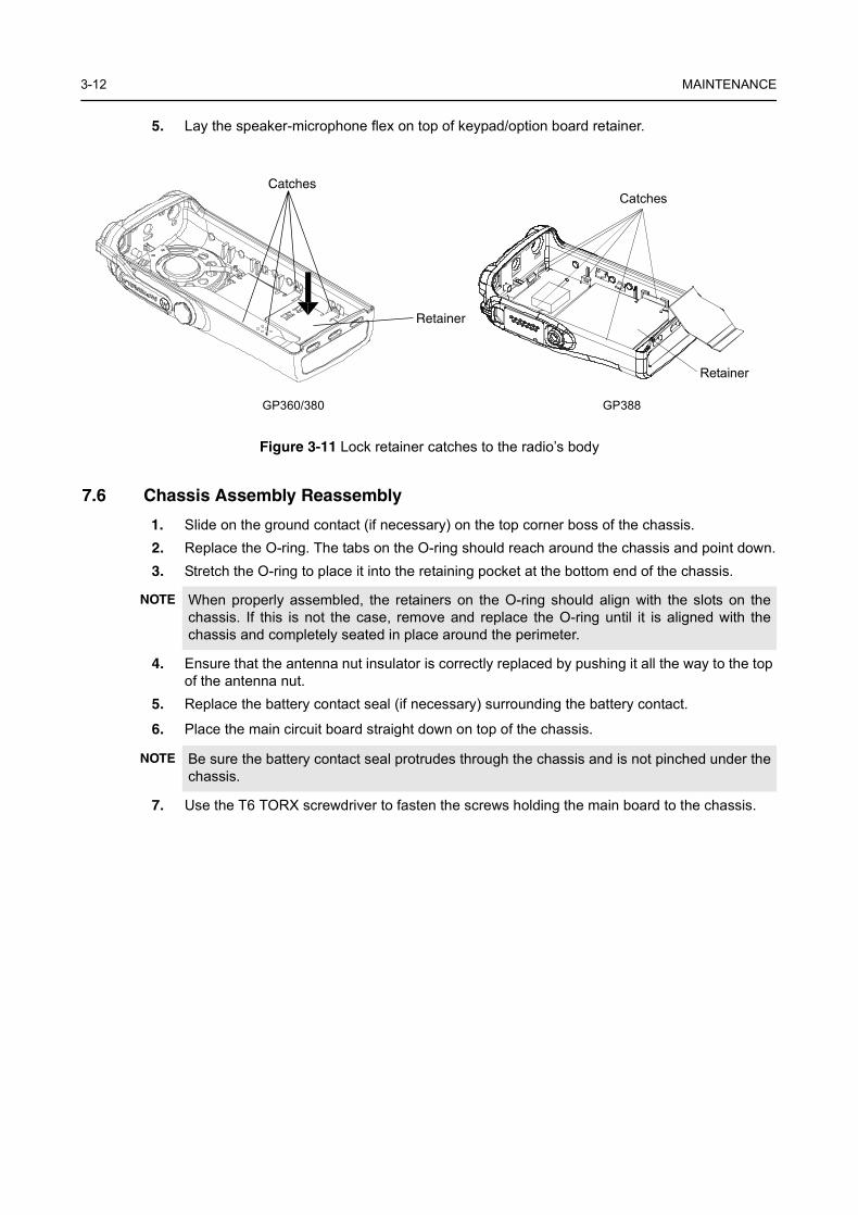
5. Lay the speaker-microphone flex on top of keypad/option board retainer.
7.6 Chassis Assembly Reassembly
1. Slide on the ground contact (if necessary) on the top corner boss of the chassis.2. Replace the O-ring. The tabs on the O-ring should reach around the chassis and point down.3. Stretch the O-ring to place it into the retaining pocket at the bottom end of the chassis.
4. Ensure that the antenna nut insulator is correctly replaced by pushing it all the way to the top of the antenna nut.
5. Replace the battery contact seal (if necessary) surrounding the battery contact.
6. Place the main circuit board straight down on top of the chassis.
7. Use the T6 TORX screwdriver to fasten the screws holding the main board to the chassis.
Figure 3-11 Lock retainer catches to the radio’s body
NOTE When properly assembled, the retainers on the O-ring should align with the slots on thechassis. If this is not the case, remove and replace the O-ring until it is aligned with thechassis and completely seated in place around the perimeter.
NOTE Be sure the battery contact seal protrudes through the chassis and is not pinched under thechassis.
Catches
Retainer
GP360/380 GP388
Retainer
Catches
Radio Reassembly — Detailed 3-13
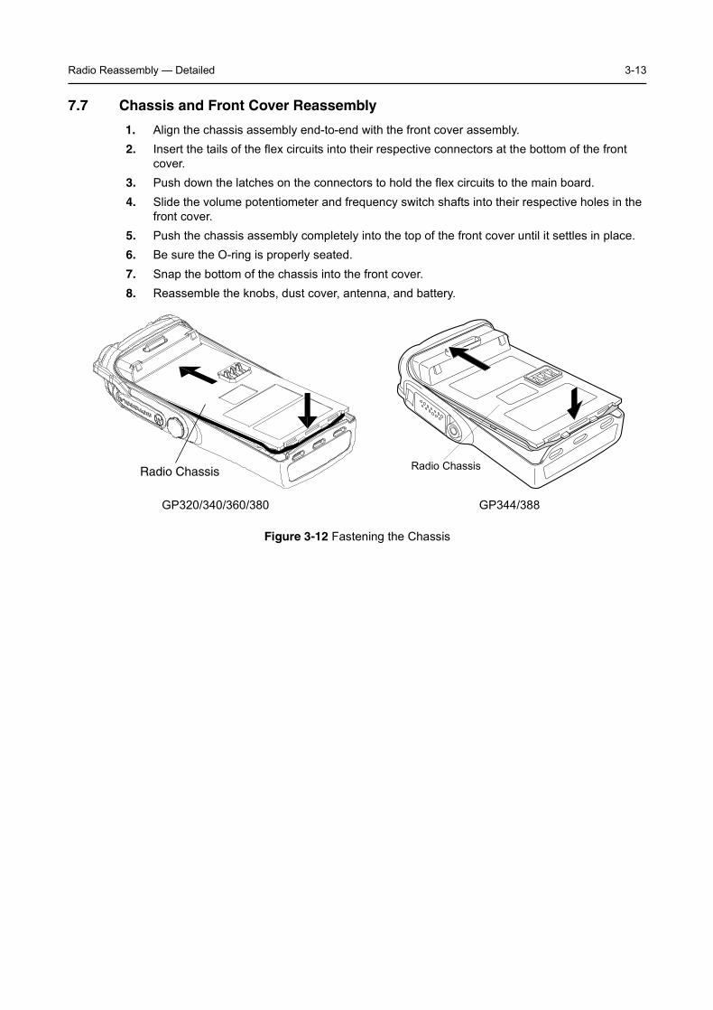
7.7 Chassis and Front Cover Reassembly
1. Align the chassis assembly end-to-end with the front cover assembly.2. Insert the tails of the flex circuits into their respective connectors at the bottom of the front
cover.3. Push down the latches on the connectors to hold the flex circuits to the main board.4. Slide the volume potentiometer and frequency switch shafts into their respective holes in the
front cover.5. Push the chassis assembly completely into the top of the front cover until it settles in place.6. Be sure the O-ring is properly seated.7. Snap the bottom of the chassis into the front cover.8. Reassemble the knobs, dust cover, antenna, and battery.
Figure 3-12 Fastening the Chassis
Radio Chassis Radio Chassis
GP320/340/360/380 GP344/388

3-14 MAINTENANCE
8.0 Option Board Installation
1. With the keypad retainer removed, the keypad backer board can be removed without the use of tools.
2. Remove the jumper flex from the connector on the keypad board. Notice the orientation of the flex to the connector. Arrows on the jumper flex point to the correct way of inserting the flex into the connector.
3. Discard the keypad backer board.4. The “breakaway” tab at the top of all option boards contains an extra row of keys and is used
to accommodate other radio models.5. Break-off and discard the option board tab, taking care not to damage the option board. Trim
any tab fragments that may remain on the option board.6. Reassemble the option board to the front cover assembly.
7. Insert the display flex circuit into the connector on the option board.8. Insert the jumper flex circuit into the connector on the option board. Notice the orientation of
the flex circuit. Arrows on the jumper flex point to the correct way of inserting the flex into the connector.
Figure 3-13 Changing the Keypad/Option Board
Retainer
Keypad/OptionBoard
Display Flex
Jumper Flex
TO
KP
Option Board Installation 3-15
9. Replace the retainer by placing the two top hooks into the slots below the speaker in the front cover; then, pivot the retainer into the front cover. Ensure that all four tab arms snap correctly into the front cover.
10. With the keypad option board, display, and retainer correctly in place, the front cover assembly can now be reassembled as described in Paragraph 7.7 (Chassis and Front Cover Reassembly).
3-16 MAINTENANCE
9.0 Mechanical Views and Parts Lists
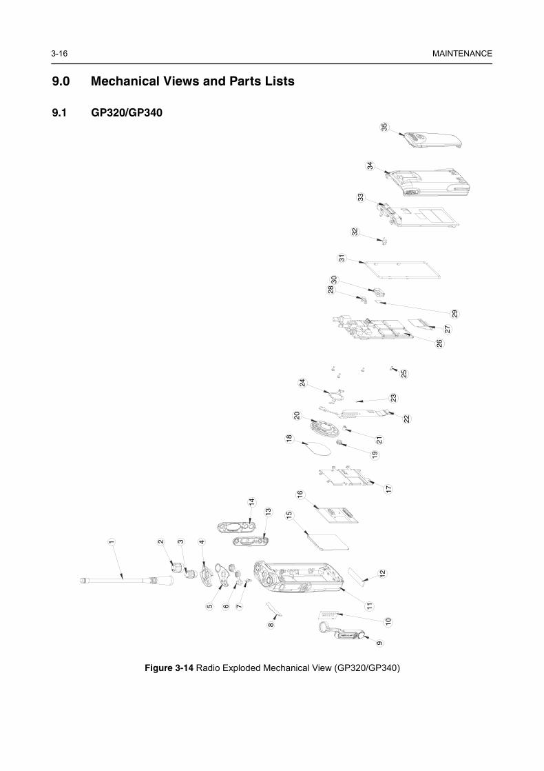
9.1 GP320/GP340
Figure 3-14 Radio Exploded Mechanical View (GP320/GP340)
8
910
11
12
13
14
15
16
18
19
20
21
22
24
23
25
2627
28
29
3031
3334
35
75 6
2 3 41
32
17
Mechanical Views and Parts Lists 3-17
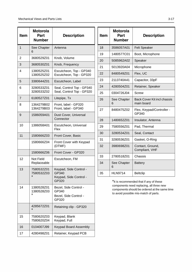
*It is recommended that if any of these components need replacing, all three new components should be ordered at the same time to avoid possible mis-match of parts.
ItemMotorola
PartNumber
Description
1 See Chapter 6
Antenna
2 3680529Z01 Knob, Volume
3 3680530Z01 Knob, Frequency
4 1380525Z011380525Z02
Escutcheon, Top - GP340Escutcheon, Top - GP320
5 3380644Z01 Escutcheon, Label
6 3280533Z013280533Z02
Seal, Control Top - GP340Seal, Control Top - GP320
7 6180527Z01 Litepipe, Tx
8 1364279B021364279B03
Front, label - GP320Front, label - GP340
9 1586059A01 Dust Cover, Universal Connector
10 1386058A01 Escutcheon, Universal Flex
11 1580666Z03 Front Cover, Basic
1580666Z04 Front Cover with Keypad (DTMF)
1580666Z06 Front Cover - GP320
12 Not Field Replaceable
Escutcheon, FM
13 7580532Z017580532Z03*
Keypad, Side Control -GP340Keypad, Side Control -GP320
14 1380528Z011380528Z03*
Bezel, Side Control - GP340Bezel, Side Control - GP320
4285672Z01*
Retaining clip - GP320
15 7580620Z037580620Z04
Keypad, Blank Keypad, Full
16 0104007J99 Keypad Board Assembly
17 4280498Z01 Retainer, Keypad PCB
18 3586057A01 Felt Speaker
19 1480577C01 Boot, Microphone
20 5085962A02 Speaker
21 5013920A04 Microphone
22 8480549Z01 Flex, UC
23 2113740A41 Capacitor, 33pF
24 4280504Z01 Retainer, Speaker
25 0304726J04 Screw
26 See Chapter 6
Back Cover Kit incl chassis main board
27 8480475Z02 Flex, Keypad/Controller - GP340
28 1480652Z01 Insulator, Antenna
29 7580556Z01 Pad, Thermal
30 3280534Z01 Seal, Contact
31 3280536Z01 Gasket, O-Ring
32 3980698Z01 Contact, Ground, Compliant, VHF
33 2780518Z01 Chassis
34 See Chapter 6
Battery
35 HLN9714 Beltclip
ItemMotorola
PartNumber
Description
3-18 MAINTENANCE
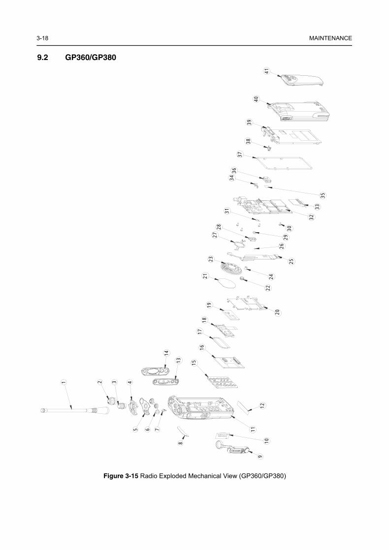
9.2 GP360/GP380
Figure 3-15 Radio Exploded Mechanical View (GP360/GP380)
8
910
11
12
13
14
15
1617
1819
20
21
22
23
24
25
27
26
28
2930
31
3233
34
35
3637
3940
41
75 6
2 3 41
38
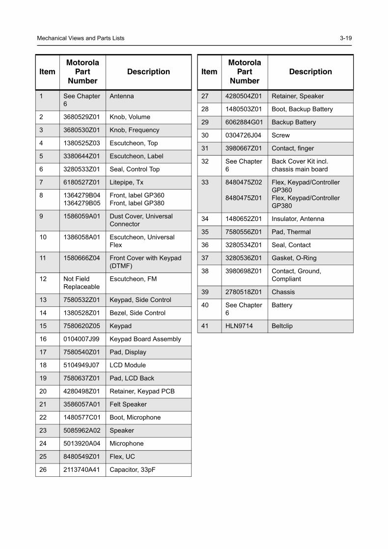
Mechanical Views and Parts Lists 3-19
ItemMotorola
PartNumber
Description
1 See Chapter 6
Antenna
2 3680529Z01 Knob, Volume
3 3680530Z01 Knob, Frequency
4 1380525Z03 Escutcheon, Top
5 3380644Z01 Escutcheon, Label
6 3280533Z01 Seal, Control Top
7 6180527Z01 Litepipe, Tx
8 1364279B041364279B05
Front, label GP360Front, label GP380
9 1586059A01 Dust Cover, Universal Connector
10 1386058A01 Escutcheon, Universal Flex
11 1580666Z04 Front Cover with Keypad (DTMF)
12 Not Field Replaceable
Escutcheon, FM
13 7580532Z01 Keypad, Side Control
14 1380528Z01 Bezel, Side Control
15 7580620Z05 Keypad
16 0104007J99 Keypad Board Assembly
17 7580540Z01 Pad, Display
18 5104949J07 LCD Module
19 7580637Z01 Pad, LCD Back
20 4280498Z01 Retainer, Keypad PCB
21 3586057A01 Felt Speaker
22 1480577C01 Boot, Microphone
23 5085962A02 Speaker
24 5013920A04 Microphone
25 8480549Z01 Flex, UC
26 2113740A41 Capacitor, 33pF
27 4280504Z01 Retainer, Speaker
28 1480503Z01 Boot, Backup Battery
29 6062884G01 Backup Battery
30 0304726J04 Screw
31 3980667Z01 Contact, finger
32 See Chapter 6
Back Cover Kit incl. chassis main board
33 8480475Z02
8480475Z01
Flex, Keypad/Controller GP360Flex, Keypad/Controller GP380
34 1480652Z01 Insulator, Antenna
35 7580556Z01 Pad, Thermal
36 3280534Z01 Seal, Contact
37 3280536Z01 Gasket, O-Ring
38 3980698Z01 Contact, Ground, Compliant
39 2780518Z01 Chassis
40 See Chapter 6
Battery
41 HLN9714 Beltclip
ItemMotorola
PartNumber
Description
3-20 MAINTENANCE
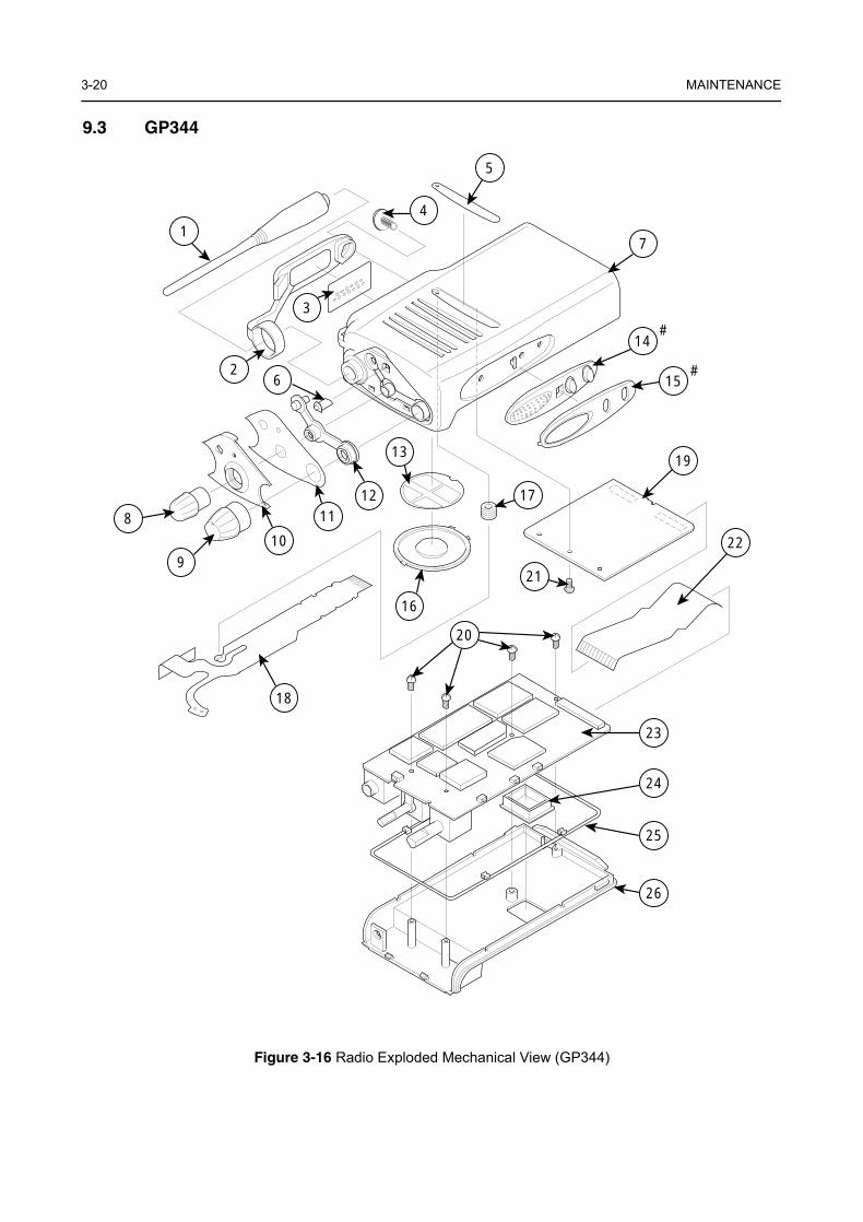
9.3 GP344
Figure 3-16 Radio Exploded Mechanical View (GP344)
6
7
8
910
1112
13
14
15
16
17
18
19
20
21
22
23
24
25
26
5
1
2
3
4
#
#

Mechanical Views and Parts Lists 3-21
* Not field serviceable
ItemMotorola
PartNumber
Description
1 See Chapter 6
Antenna
2 JMLN4638_ Dust Cover
3 1385905Z01 Universal Connector Seal
4 0302020P03 Screw for Dust Cover
5 3385959Z07 Front, label GP344
6 6102001P10 Light Pipe
7 0104031G98 Front Cover Assembly
8 3680530Z02 Frequency Knob
9 3680529Z01 Volume Knob
10 1302012P06 Top Plastic Plate
11 3385906Z01 Top Sheet
12 3202000P15 Top Seal Rubber
13 3502416P03 Speaker Mesh
14* Part of Item 7 PTT Rubber
15* Part of Item 7 PTT Plastic Cover
16 5005679X01 Speaker
17 1480577C01 Boot Microphone
18 8404079G01 Flex PCB Universal
19* 8404051G07 Controller Board
20 0385913Z01 4 M2x4 Philips Screws
21 0302020P05 1 M2x1 Philips Screw
22 8404078G01 Flex PCB RF Controller
23* 8404055G05 RF Board (VHF)
8404077G01 RF Board (UHF)
8485641Z02 RF Board (UHF 2)
24 3280534Z01 Seal Contact
25 3202000P14 O-ring
26 1502001P31 Chassis
3-22 MAINTENANCE
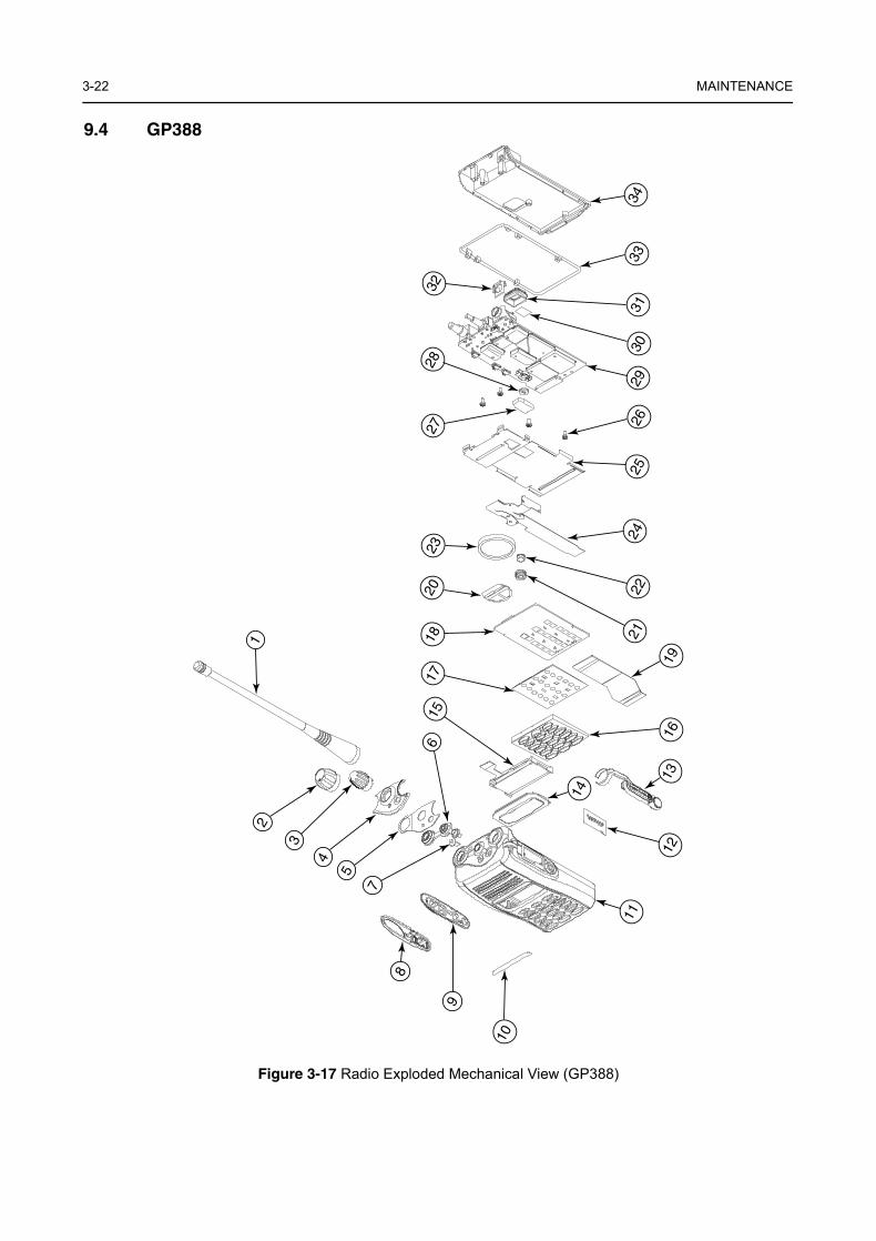
9.4 GP388
Figure 3-17 Radio Exploded Mechanical View (GP388)
12
3
4
5
6
7
8
9
10
11
12
14
15
16
1718
20
19
2122
23
2425
262728
2930
31
32
3334
13
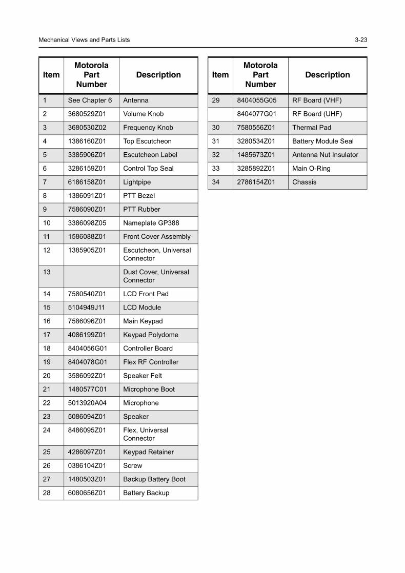
Mechanical Views and Parts Lists 3-23
ItemMotorola
PartNumber
Description
1 See Chapter 6 Antenna
2 3680529Z01 Volume Knob
3 3680530Z02 Frequency Knob
4 1386160Z01 Top Escutcheon
5 3385906Z01 Escutcheon Label
6 3286159Z01 Control Top Seal
7 6186158Z01 Lightpipe
8 1386091Z01 PTT Bezel
9 7586090Z01 PTT Rubber
10 3386098Z05 Nameplate GP388
11 1586088Z01 Front Cover Assembly
12 1385905Z01 Escutcheon, Universal Connector
13 Dust Cover, Universal Connector
14 7580540Z01 LCD Front Pad
15 5104949J11 LCD Module
16 7586096Z01 Main Keypad
17 4086199Z01 Keypad Polydome
18 8404056G01 Controller Board
19 8404078G01 Flex RF Controller
20 3586092Z01 Speaker Felt
21 1480577C01 Microphone Boot
22 5013920A04 Microphone
23 5086094Z01 Speaker
24 8486095Z01 Flex, Universal Connector
25 4286097Z01 Keypad Retainer
26 0386104Z01 Screw
27 1480503Z01 Backup Battery Boot
28 6080656Z01 Battery Backup
29 8404055G05 RF Board (VHF)
8404077G01 RF Board (UHF)
30 7580556Z01 Thermal Pad
31 3280534Z01 Battery Module Seal
32 1485673Z01 Antenna Nut Insulator
33 3285892Z01 Main O-Ring
34 2786154Z01 Chassis
ItemMotorola
PartNumber
Description
3-24 MAINTENANCE
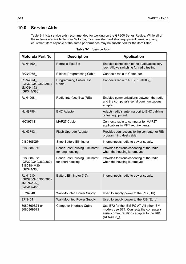
10.0 Service Aids
Table 3-1 lists service aids recommended for working on the GP300 Series Radios. While all of these items are available from Motorola, most are standard shop equipment items, and any equivalent item capable of the same performance may be substituted for the item listed.
Table 3-1 Service Aids
Motorola Part No. Description Application
RLN4460_ Portable Test Set Enables connection to the audio/accessory jack. Allows switching for radio testing.
RKN4075_ Ribless Programming Cable Connects radio to Computer.
RKN4074_(GP320/340/360/380)JMKN4123_(GP344/388)
Programming Cable/Test Cable
Connects radio to RIB (RLN4008_).
RLN4008_ Radio Interface Box (RIB) Enables communications between the radio and the computer’s serial communications adapter.
HLN9756_ BNC Adaptor Adapts radio’s antenna port to BNC cabling of test equipment.
HKN9743_ MAP27 Cable Connects radio to computer for MAP27 applications in MPT requirements.
HLN9742_ Flash Upgrade Adapter Provides connections to the computer or RIB programming /test cable
0180305G54 Shop Battery Eliminator Interconnects radio to power supply.
8180384F66 Bench Test Housing Eliminator for long housing.
Provides for troubleshooting of the radio when the housing is removed.
8180384F68(GP320/340/360/380)8180384M30(GP344/388)
Bench Test Housing Eliminator for short housing.
Provides for troubleshooting of the radio when the housing is removed.
RLN4510(GP320/340/360/380)JMKN4125_(GP344/388)
Battery Eliminator 7.5V Interconnects radio to power supply.
EPN4040 Wall-Mounted Power Supply Used to supply power to the RIB (UK).
EPN4041 Wall-Mounted Power Supply Used to supply power to the RIB (Euro)
3080369B71 or 3080369B72
Computer Interface Cable Use B72 for the IBM PC AT. All other IBM models use B71. Connects the computer’s serial communications adapter to the RIB. (RLN4008_)
Test Equipment 3-25
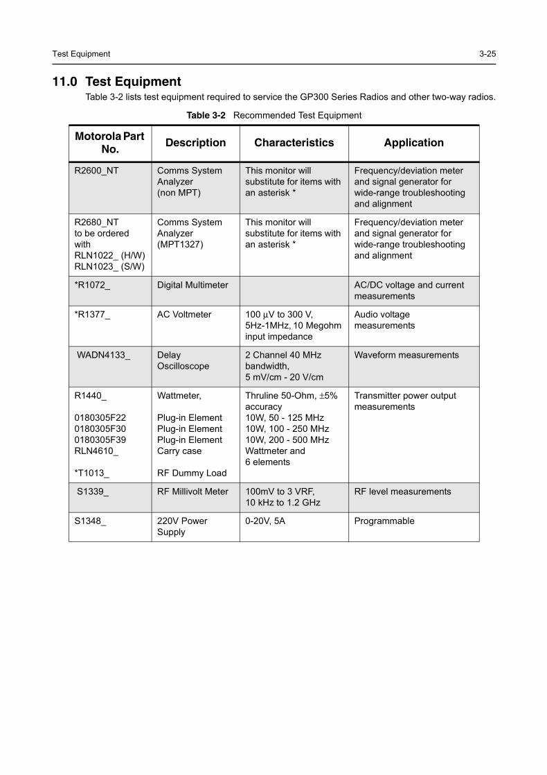
11.0 Test EquipmentTable 3-2 lists test equipment required to service the GP300 Series Radios and other two-way radios.
Table 3-2 Recommended Test Equipment
Motorola Part No. Description Characteristics Application
R2600_NT Comms System Analyzer (non MPT)
This monitor will substitute for items with an asterisk *
Frequency/deviation meter and signal generator for wide-range troubleshooting and alignment
R2680_NTto be ordered with RLN1022_ (H/W)RLN1023_ (S/W)
Comms System Analyzer (MPT1327)
This monitor will substitute for items with an asterisk *
Frequency/deviation meter and signal generator for wide-range troubleshooting and alignment
*R1072_ Digital Multimeter AC/DC voltage and current measurements
*R1377_ AC Voltmeter 100 µV to 300 V, 5Hz-1MHz, 10 Megohm input impedance
Audio voltagemeasurements
WADN4133_ Delay Oscilloscope
2 Channel 40 MHz bandwidth,5 mV/cm - 20 V/cm
Waveform measurements
R1440_
0180305F220180305F300180305F39RLN4610_
*T1013_
Wattmeter,
Plug-in ElementPlug-in ElementPlug-in ElementCarry case
RF Dummy Load
Thruline 50-Ohm, ±5% accuracy 10W, 50 - 125 MHz10W, 100 - 250 MHz10W, 200 - 500 MHz Wattmeter and6 elements
Transmitter power output measurements
S1339_ RF Millivolt Meter 100mV to 3 VRF, 10 kHz to 1.2 GHz
RF level measurements
S1348_ 220V Power Supply
0-20V, 5A Programmable
3-26 MAINTENANCE
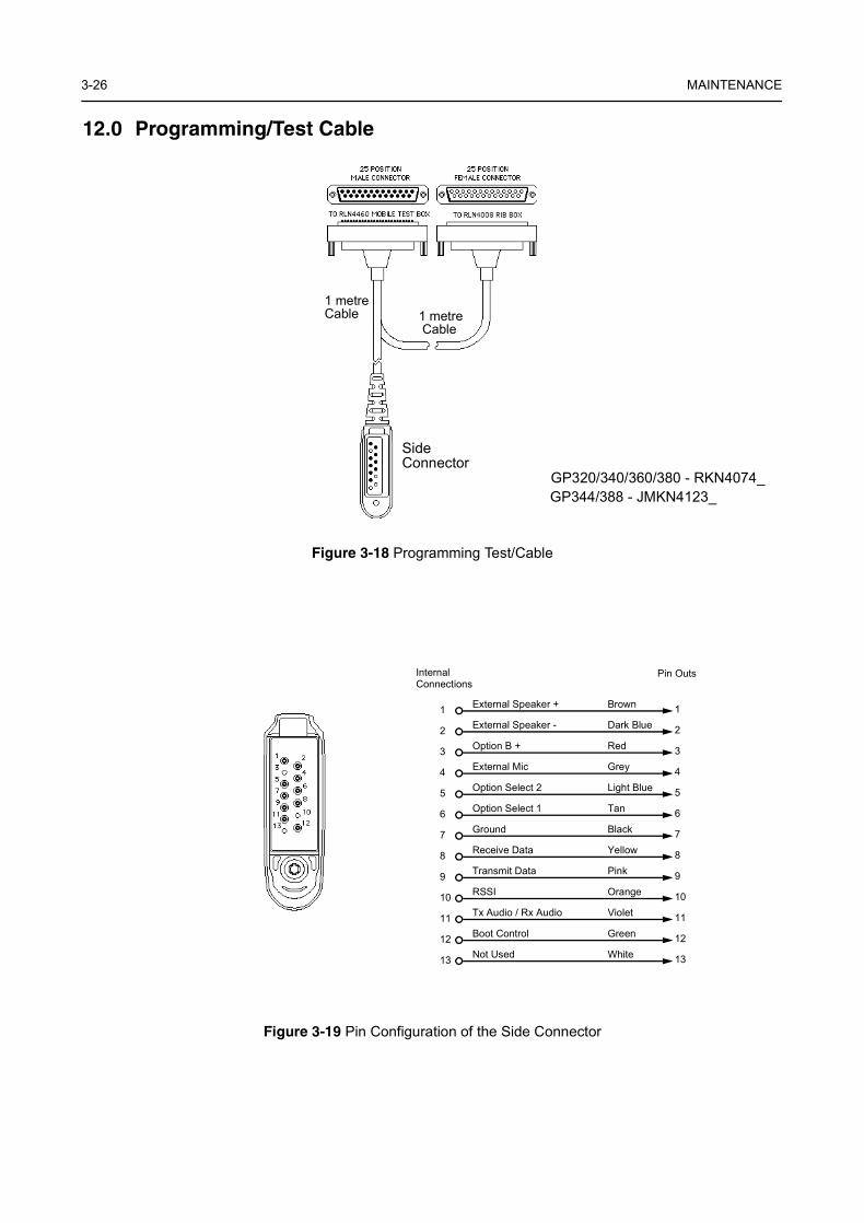
12.0 Programming/Test Cable
Figure 3-18 Programming Test/Cable
Figure 3-19 Pin Configuration of the Side Connector
SideConnector
1 metreCable
1 metreCable
GP320/340/360/380 - RKN4074_GP344/388 - JMKN4123_
External Speaker + Brown 11External Speaker - Dark Blue 22Option B + Red 33External Mic Grey 44Option Select 2 Light Blue 55Option Select 1 Tan 66Ground Black 77Receive Data Yellow 88Transmit Data Pink 99RSSI Orange 1010Tx Audio / Rx Audio Violet 1111Boot Control Green 1212Not Used White 1313
Internal Connections
Pin Outs
Programming/Test Cable 3-27
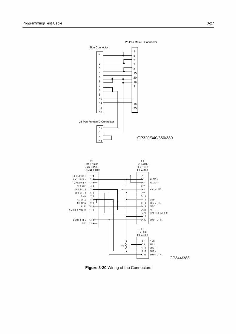
Figure 3-20 Wiring of the Connectors
1
2345678910111213
151411
25 Pos Female D Connector
25 Pos Male D Connector
Side Connector152781520169
1825
GP320/340/360/380
1
2
5
7
8
9
16
18
19
2021
22
25
15
AUDIO -
AUDIO +
MIC AUDIO
GND
VOL CTRL
DISC
PTTOPT SEL INT/EXT
BOOT CTRL
1
4
15
25
11
GND
BIAS
BUS +
BOOT CTRL
BUS -
1
2
3
4
5
6
8
9
10
11
12
13
7
EXT SPKR +
EXT SPKR -
OPTION B+
EXT MIC
OPT SEL 2
OPT SEL 1
RX DATA
TX DATA
RSSI
XMIT/RX AUDIO
BOOT CTRL
N/C
GND
P2TO RADIOTEST SETRLN4460
P1TO RADIO
UNIVERSALCONNECTOR
J1TO RIB
RLN4008
10K
GP344/388

3-28 MAINTENANCE
Chapter 4
PERFORMANCE TESTING
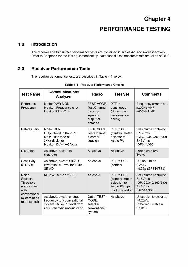
1.0 Introduction
The receiver and transmitter performance tests are contained in Tables 4-1 and 4-2 respectively. Refer to Chapter 5 for the test equipment set up. Note that all test measurements are taken at 25°C.
2.0 Receiver Performance Tests
The receiver performance tests are described in Table 4-1 below.
Table 4-1 Receiver Performance Checks
Test Name Communications Analyzer Radio Test Set Comments
Reference Frequency
Mode: PWR MONMonitor: Frequency errorInput at RF In/Out
TEST MODE,Test Channel 4 carrier squelch output at antenna
PTT to continuous (during the performance check)
Frequency error to be ±200Hz VHF±600Hz UHF
Rated Audio Mode: GENOutput level: 1.0mV RFMod: 1kHz tone at 3kHz deviationMonitor: DVM: AC Volts
TEST MODETest Channel 4 carrier squelch
PTT to OFF (centre), meter selector to Audio PA
Set volume control to 3.16Vrms(GP320/340/360/380)3.46Vrms(GP344/388)
Distortion As above, except to distortion
As above As above Distortion 3.0%Typical
Sensitivity (SINAD)
As above, except SINAD, lower the RF level for 12dB SINAD.
As above PTT to OFF (center)
RF input to be0.25µV<0.35µ (GP344/388)
Noise Squelch Threshold (only radios with conventional system need to be tested)
RF level set to 1mV RF As above PTT to OFF (center), meter selection to Audio PA, spkr/load to speaker
Set volume control to 3.16Vrms(GP320/340/360/380)3.46Vrms(GP344/388)
As above, except change frequency to a conventional system. Raise RF level from zero until radio unsquelches.
Out of TEST MODE; select a conventional system
As above Unsquelch to occur at <0.25µV.Preferred SINAD = 9-10dB
4-2 PERFORMANCE TESTING
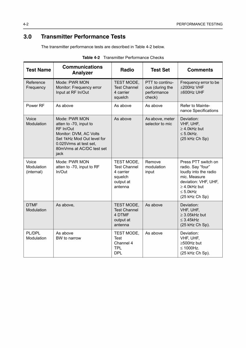
3.0 Transmitter Performance Tests
The transmitter performance tests are described in Table 4-2 below.
Table 4-2 Transmitter Performance Checks
Test Name Communications Analyzer Radio Test Set Comments
Reference Frequency
Mode: PWR MONMonitor: Frequency errorInput at RF In/Out
TEST MODE,Test Channel 4 carrier squelch
PTT to continu-ous (during the performance check)
Frequency error to be ±200Hz VHF±600Hz UHF
Power RF As above As above As above Refer to Mainte-nance Specifications
Voice Modulation
Mode: PWR MONatten to -70, input to RF In/OutMonitor: DVM, AC VoltsSet 1kHz Mod Out level for 0.025Vrms at test set,80mVrms at AC/DC test set jack
As above As above, meter selector to mic
Deviation:VHF, UHF, ≥ 4.0kHz but ≤ 5.0kHz.(25 kHz Ch Sp)
Voice Modulation (internal)
Mode: PWR MONatten to -70, input to RF In/Out
TEST MODE, Test Channel 4 carrier squelch output at antenna
Remove modulation input
Press PTT switch on radio. Say “four” loudly into the radio mic. Measure deviation: VHF, UHF, ≥ 4.0kHz but ≤ 5.0kHz(25 kHz Ch Sp)
DTMF Modulation
As above, TEST MODE, Test Channel 4 DTMF output at antenna
As above Deviation: VHF, UHF, ≥ 3.05kHz but ≤ 3.45kHz(25 kHz Ch Sp).
PL/DPL Modulation
As aboveBW to narrow
TEST MODE, Test Channel 4TPLDPL
As above Deviation:VHF, UHF, ≥500Hz but ≤ 1000Hz.(25 kHz Ch Sp).
Chapter 5
RADIO TUNING AND PROGRAMMING
1.0 IntroductionThis chapter provides an overview of the Customer Programming Software (CPS) and tuner program which are designed for use in a Windows 95/98 environment. These programs are available in separate kits as listed in the Table 5-1. An Installation instruction manual is also included with each kit.
Table 5-1 Software Installation Kits Radio Tuning Setup
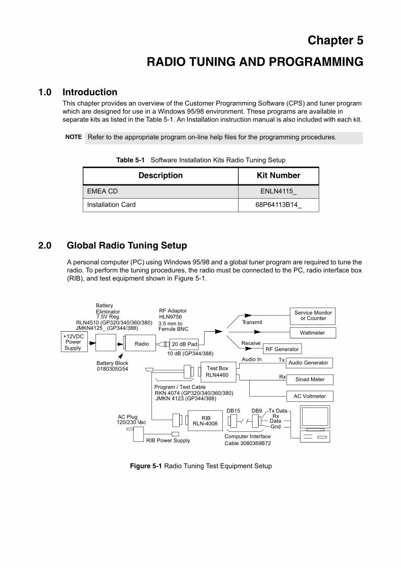
2.0 Global Radio Tuning Setup
A personal computer (PC) using Windows 95/98 and a global tuner program are required to tune the radio. To perform the tuning procedures, the radio must be connected to the PC, radio interface box (RIB), and test equipment shown in Figure 5-1.
Figure 5-1 Radio Tuning Test Equipment Setup
NOTE Refer to the appropriate program on-line help files for the programming procedures.
Description Kit Number
EMEA CD ENLN4115_
Installation Card 68P64113B14_
Wattmeter
Audio Generator
Sinad Meter
AC Voltmeter
20 dB Pad
Battery Block
PowerSupply
Audio In Tx
Rx
Receive
Transmit
RF Generator
RF AdaptorHLN9756
RIBRLN-4008
RIB Power Supply
RLN4460Test Box
Rx GndData
Tx Data
Radio
Computer InterfaceCable 3080369B72
Program / Test CableRKN 4074 (GP320/340/360/380)
Service Monitoror Counter
DB15 DB9AC Plug120/230 Vac
3.5 mm toFerrule BNC
RLN4510 (GP320/340/360/380)
+12VDC
0180305G54
Eliminator7.5V Reg.
Battery
JMKN4125_ (GP344/388)
10 dB (GP344/388)
JMKN 4123 (GP344/388)
5-2 RADIO TUNING AND PROGRAMMING
2.1 Initial Test Equipment Setup
The supply voltage is connected to the radio using a Motorola battery eliminator, P/N 0180305G54. The initial test equipment (Figure 5-1) control settings are listed in Table 5-2.
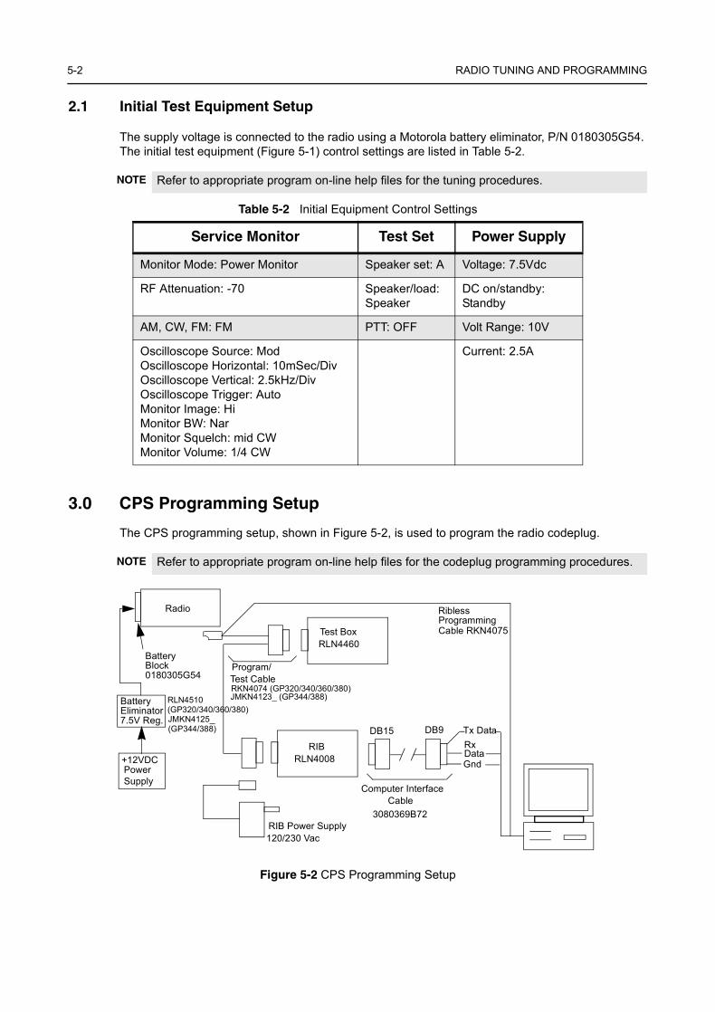
3.0 CPS Programming Setup
The CPS programming setup, shown in Figure 5-2, is used to program the radio codeplug.
Figure 5-2 CPS Programming Setup
NOTE Refer to appropriate program on-line help files for the tuning procedures.
Table 5-2 Initial Equipment Control Settings
Service Monitor Test Set Power Supply
Monitor Mode: Power Monitor Speaker set: A Voltage: 7.5Vdc
RF Attenuation: -70 Speaker/load: Speaker
DC on/standby: Standby
AM, CW, FM: FM PTT: OFF Volt Range: 10V
Oscilloscope Source: ModOscilloscope Horizontal: 10mSec/DivOscilloscope Vertical: 2.5kHz/DivOscilloscope Trigger: AutoMonitor Image: HiMonitor BW: NarMonitor Squelch: mid CWMonitor Volume: 1/4 CW
Current: 2.5A
NOTE Refer to appropriate program on-line help files for the codeplug programming procedures.
RIBRLN4008
RIB Power Supply
RLN4460Test Box
Rx GndData
Tx Data
Radio
Battery
Computer Interface Cable
Program/
RKN4074 (GP320/340/360/380)Test Cable
3080369B72
DB15 DB9
120/230 Vac
Power Supply
RLN4510
+12VDC
BatteryEliminator7.5V Reg.
Block0180305G54
RiblessProgramming Cable RKN4075
(GP320/340/360/380)JMKN4125_(GP344/388)
JMKN4123_ (GP344/388)
Chapter 6
MODEL CHART AND TEST SPECIFICATION
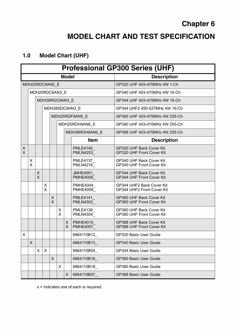
1.0 Model Chart (UHF)
Professional GP300 Series (UHF)Model Description
MDH25RDC9AN0_E GP320 UHF 403-470MHz 4W 1-Ch
MDH25RDC9AN3_E GP340 UHF 403-470MHz 4W 16-Ch
MDH38RDC9AN3_E GP344 UHF 403-470MHz 4W 16-Ch
MDH38SDC9AN3_E GP344 UHF2 450-527MHz 4W 16-Ch
MDH25RDF9AN5_E GP360 UHF 403-470MHz 4W 255-Ch
MDH25RDH9AN6_E GP380 UHF 403-470MHz 4W 255-Ch
MDH38RDH9AN6_E GP388 UHF 403-470MHz 4W 255-Ch
Item Description
XX
PMLE4140_PMLN4253_
GP320 UHF Back Cover KitGP320 UHF Front Cover Kit
XX
PMLE4137_PMLN4216_
GP340 UHF Back Cover KitGP340 UHF Front Cover Kit
XX
JMHE4001_PMHE4006_
GP344 UHF Back Cover KitGP344 UHF Front Cover Kit
XX
PMHE4004_PMHE4008_
GP344 UHF2 Back Cover KitGP344 UHF2 Front Cover Kit
XX
PMLE4141_PMLN4302_
GP360 UHF Back Cover KitGP360 UHF Front Cover Kit
XX
PMLE4138_PMLN4304_
GP380 UHF Back Cover KitGP380 UHF Front Cover Kit
XX
PMHE4010_PMHE4007_
GP388 UHF Back Cover KitGP388 UHF Front Cover Kit
X 6864110B12_ GP320 Basic User Guide
X 6864110B13_ GP340 Basic User Guide
X X 6864110B54_ GP344 Basic User Guide
X 6864110B16_ GP360 Basic User Guide
X 6864110B18_ GP380 Basic User Guide
X 6864110B97_ GP388 Basic User Guide
x = Indicates one of each is required.
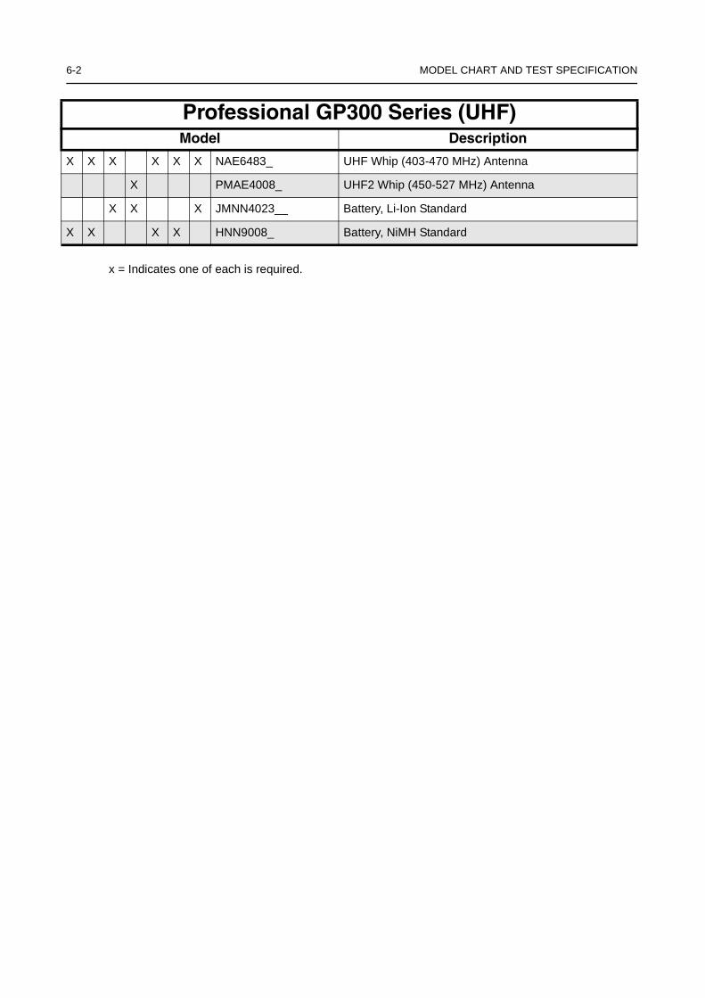
6-2 MODEL CHART AND TEST SPECIFICATION
X X X X X X NAE6483_ UHF Whip (403-470 MHz) Antenna
X PMAE4008_ UHF2 Whip (450-527 MHz) Antenna
X X X JMNN4023__ Battery, Li-Ion Standard
X X X X HNN9008_ Battery, NiMH Standard
Professional GP300 Series (UHF)Model Description
x = Indicates one of each is required.

Model Chart (VHF) 6-3
2.0 Model Chart (VHF)
Professional GP300 Series (VHF)Model Description
MDH25KDC9AN0_E GP320 VHF 136-174MHz 5W 1-Ch
MDH25KDC9AN3_E GP340 VHF 136-174MHz 5W 16-Ch
MDH38KDC9AN3_E GP344 VHF 136-174MHz 5W 16-Ch
MDH25KDF9AN5_E GP360 VHF 136-174MHz 5W 255-Ch
MDH25KDH9AN6_E GP380 VHF 136-174MHz 5W 255-Ch
MDH38KDH9AN6_E GP388 VHF 136-174MHz 5W 255-Ch
Item Description
XX
PMLD4121_PMLN4253_
GP320 VHF Back Cover KitGP320 VHF Front Cover Kit
XX
PMLD4117_PMLN4216_
GP340 VHF Back Cover KitGP340 VHF Front Cover Kit
XX
JMHD4005_PMHD4004_
GP344 VHF Back Cover KitGP344 VHF Front Cover Kit
XX
PMLD4119_PMLN4302_
GP360 VHF Back Cover KitGP360 VHF Front Cover Kit
XX
PMLD4118_PMLN4304_
GP380 VHF Back Cover KitGP380 VHF Front Cover Kit
XX
PMHD4006_PMHD4005__
GP388 VHF Back Cover KitGP388 VHF Front Cover Kit
X 6864110B12_ GP320 Basic User Guide
X 6864110B13_ GP340 Basic User Guide
X 6864110B54_ GP344 Basic User Guide
X 6864110B16_ GP360 Basic User Guide
X 6864110B18_ GP380 Basic User Guide
X 6864110B97_ GP388 Basic User Guide
X X X X X X PMAD4023_ VHF 14cm (150-161 MHz) Antenna
X X X X HNN9008_ Battery, NiMH Standard
X X JMNN4023__ Battery, Li-Ion Standard
x = Indicates one of each is required.
6-4 MODEL CHART AND TEST SPECIFICATION
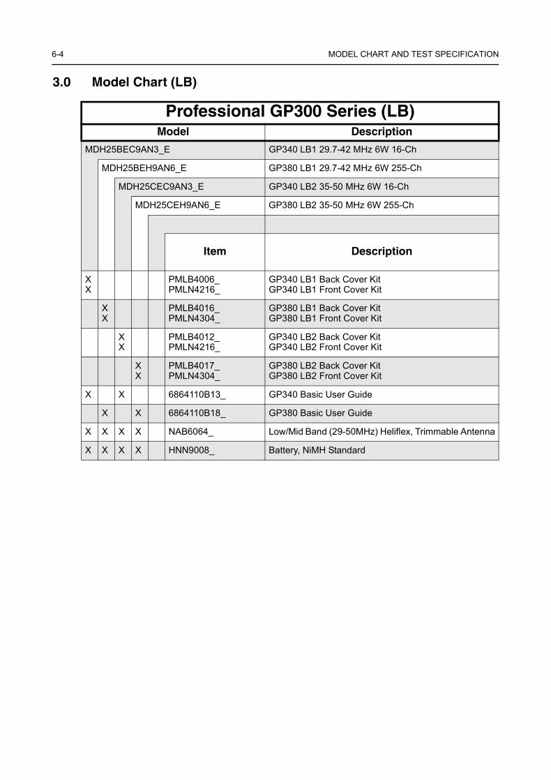
3.0 Model Chart (LB)
Professional GP300 Series (LB)Model Description
MDH25BEC9AN3_E GP340 LB1 29.7-42 MHz 6W 16-Ch
MDH25BEH9AN6_E GP380 LB1 29.7-42 MHz 6W 255-Ch
MDH25CEC9AN3_E GP340 LB2 35-50 MHz 6W 16-Ch
MDH25CEH9AN6_E GP380 LB2 35-50 MHz 6W 255-Ch
Item Description
XX
PMLB4006_PMLN4216_
GP340 LB1 Back Cover KitGP340 LB1 Front Cover Kit
XX
PMLB4016_PMLN4304_
GP380 LB1 Back Cover KitGP380 LB1 Front Cover Kit
XX
PMLB4012_PMLN4216_
GP340 LB2 Back Cover KitGP340 LB2 Front Cover Kit
XX
PMLB4017_PMLN4304_
GP380 LB2 Back Cover KitGP380 LB2 Front Cover Kit
X X 6864110B13_ GP340 Basic User Guide
X X 6864110B18_ GP380 Basic User Guide
X X X X NAB6064_ Low/Mid Band (29-50MHz) Heliflex, Trimmable Antenna
X X X X HNN9008_ Battery, NiMH Standard

Model Chart (300R1) 6-5
4.0 Model Chart (300R1)
Professional GP300 Series (300R1)Model Description
MDH25EDC9AN3_E GP340 300R1 300-350 MHz 4W
Item Description
XX
PMLD4141_PMLN4216_
GP340 300R1 Back Cover KitGP340 300R1 Front Cover Kit
X 6864110B13_ GP340 Basic User Guide
X PMAD4022_ VHF 9cm (300-344 MHz) Antenna
X HNN9008_ Battery, NiMH Standard
x = Indicates one of each is required.
6-6 MODEL CHART AND TEST SPECIFICATION
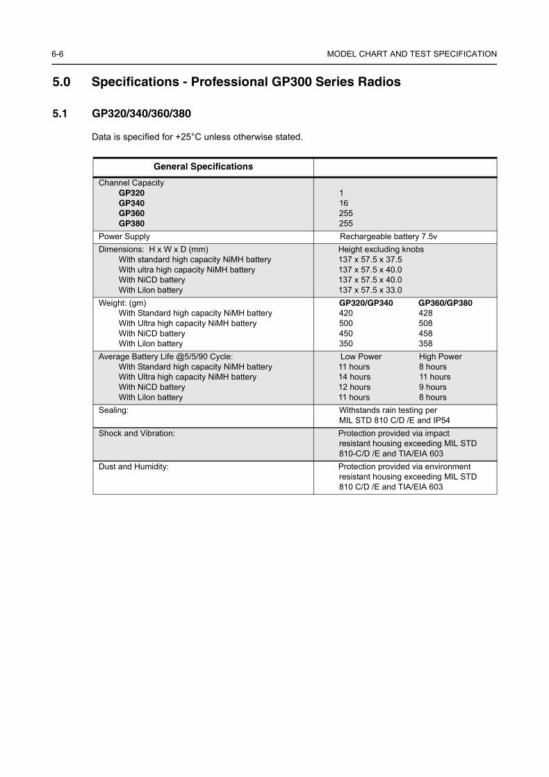
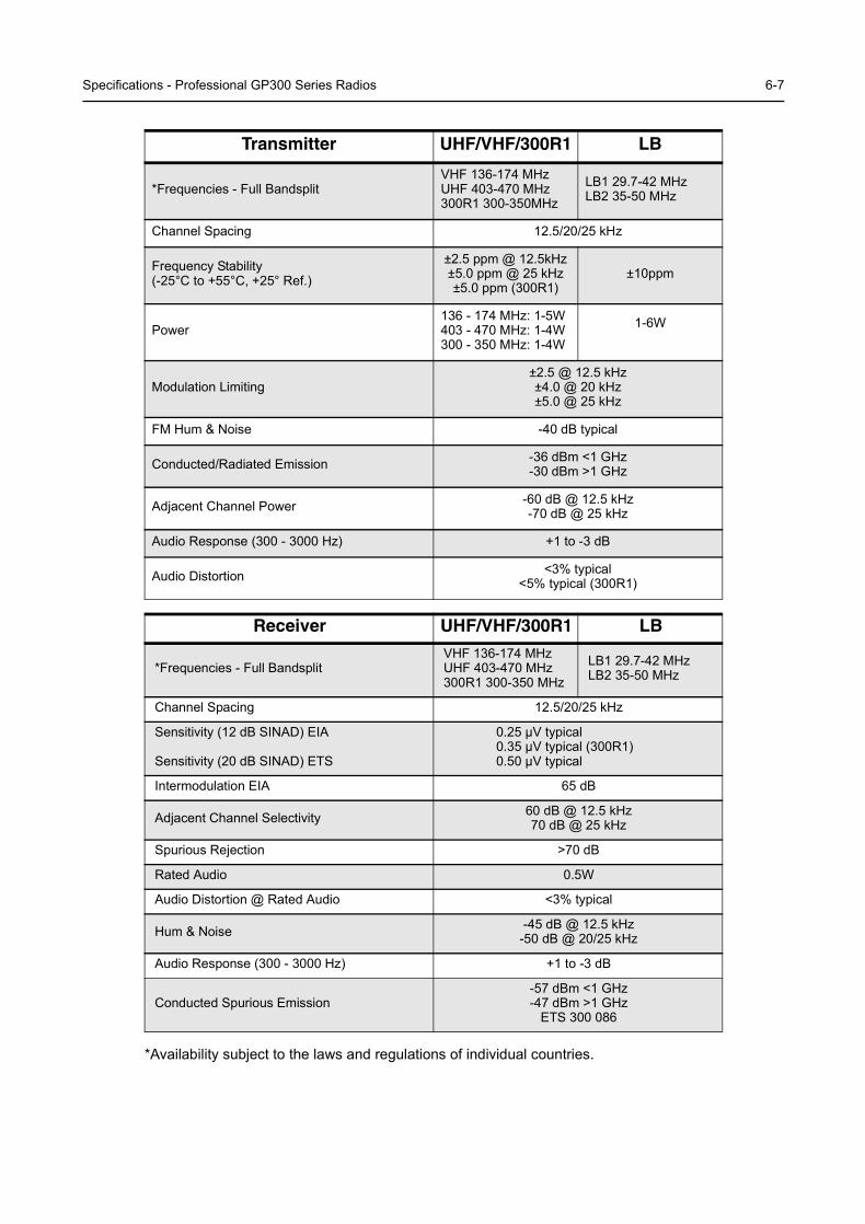
5.0 Specifications - Professional GP300 Series Radios
5.1 GP320/340/360/380
Data is specified for +25°C unless otherwise stated.
General Specifications
Channel CapacityGP320GP340GP360GP380
116255255
Power Supply Rechargeable battery 7.5vDimensions: H x W x D (mm)
With standard high capacity NiMH batteryWith ultra high capacity NiMH batteryWith NiCD batteryWith Lilon battery
Height excluding knobs137 x 57.5 x 37.5137 x 57.5 x 40.0137 x 57.5 x 40.0137 x 57.5 x 33.0
Weight: (gm)With Standard high capacity NiMH batteryWith Ultra high capacity NiMH batteryWith NiCD batteryWith Lilon battery
GP320/GP340 GP360/GP380420 428500 508450 458350 358
Average Battery Life @5/5/90 Cycle:With Standard high capacity NiMH batteryWith Ultra high capacity NiMH batteryWith NiCD batteryWith Lilon battery
Low Power High Power11 hours 8 hours14 hours 11 hours12 hours 9 hours11 hours 8 hours
Sealing: Withstands rain testing per MIL STD 810 C/D /E and IP54
Shock and Vibration: Protection provided via impactresistant housing exceeding MIL STD 810-C/D /E and TIA/EIA 603
Dust and Humidity: Protection provided via environment resistant housing exceeding MIL STD 810 C/D /E and TIA/EIA 603
Specifications - Professional GP300 Series Radios 6-7
*Availability subject to the laws and regulations of individual countries.
Transmitter UHF/VHF/300R1 LB
*Frequencies - Full BandsplitVHF 136-174 MHzUHF 403-470 MHz300R1 300-350MHz
LB1 29.7-42 MHzLB2 35-50 MHz
Channel Spacing 12.5/20/25 kHz
Frequency Stability(-25°C to +55°C, +25° Ref.)
±2.5 ppm @ 12.5kHz±5.0 ppm @ 25 kHz±5.0 ppm (300R1)
±10ppm
Power136 - 174 MHz: 1-5W403 - 470 MHz: 1-4W300 - 350 MHz: 1-4W
1-6W
Modulation Limiting±2.5 @ 12.5 kHz ±4.0 @ 20 kHz±5.0 @ 25 kHz
FM Hum & Noise -40 dB typical
Conducted/Radiated Emission -36 dBm <1 GHz-30 dBm >1 GHz
Adjacent Channel Power -60 dB @ 12.5 kHz-70 dB @ 25 kHz
Audio Response (300 - 3000 Hz) +1 to -3 dB
Audio Distortion <3% typical<5% typical (300R1)
Receiver UHF/VHF/300R1 LB
*Frequencies - Full BandsplitVHF 136-174 MHzUHF 403-470 MHz300R1 300-350 MHz
LB1 29.7-42 MHzLB2 35-50 MHz
Channel Spacing 12.5/20/25 kHz
Sensitivity (12 dB SINAD) EIA
Sensitivity (20 dB SINAD) ETS
0.25 µV typical0.35 µV typical (300R1)0.50 µV typical
Intermodulation EIA 65 dB
Adjacent Channel Selectivity 60 dB @ 12.5 kHz 70 dB @ 25 kHz
Spurious Rejection >70 dB
Rated Audio 0.5W
Audio Distortion @ Rated Audio <3% typical
Hum & Noise -45 dB @ 12.5 kHz-50 dB @ 20/25 kHz
Audio Response (300 - 3000 Hz) +1 to -3 dB
Conducted Spurious Emission-57 dBm <1 GHz-47 dBm >1 GHz
ETS 300 086
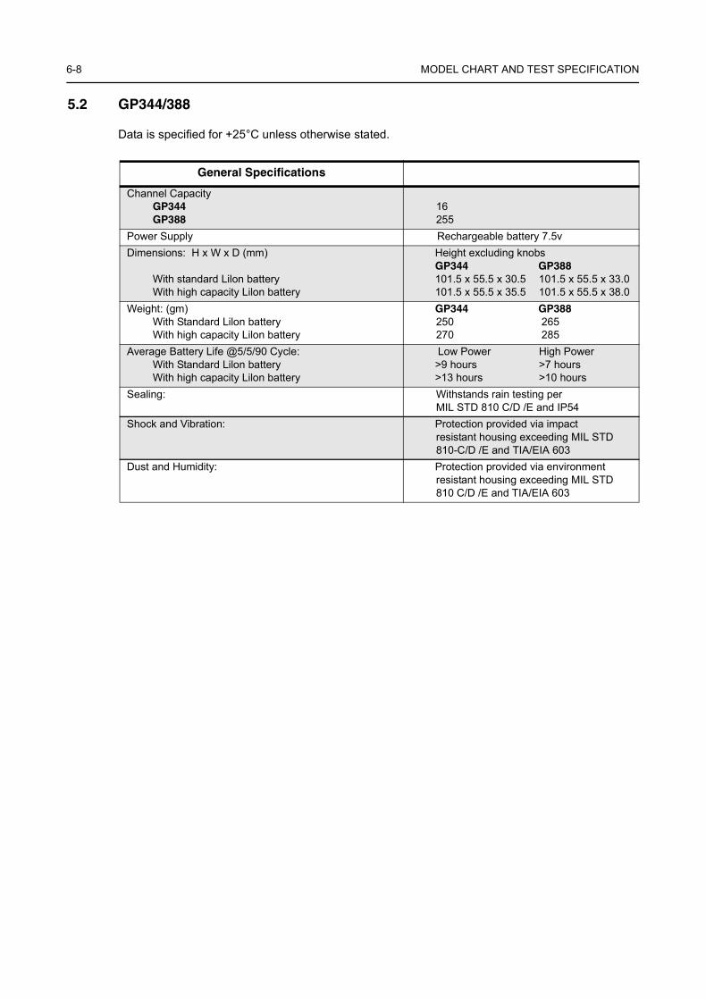
6-8 MODEL CHART AND TEST SPECIFICATION
5.2 GP344/388
Data is specified for +25°C unless otherwise stated.
General Specifications
Channel CapacityGP344GP388
16255
Power Supply Rechargeable battery 7.5vDimensions: H x W x D (mm)
With standard Lilon batteryWith high capacity Lilon battery
Height excluding knobsGP344 GP388101.5 x 55.5 x 30.5 101.5 x 55.5 x 33.0101.5 x 55.5 x 35.5 101.5 x 55.5 x 38.0
Weight: (gm)With Standard Lilon batteryWith high capacity Lilon battery
GP344 GP388250 265270 285
Average Battery Life @5/5/90 Cycle:With Standard Lilon batteryWith high capacity Lilon battery
Low Power High Power>9 hours >7 hours>13 hours >10 hours
Sealing: Withstands rain testing per MIL STD 810 C/D /E and IP54
Shock and Vibration: Protection provided via impactresistant housing exceeding MIL STD 810-C/D /E and TIA/EIA 603
Dust and Humidity: Protection provided via environment resistant housing exceeding MIL STD 810 C/D /E and TIA/EIA 603
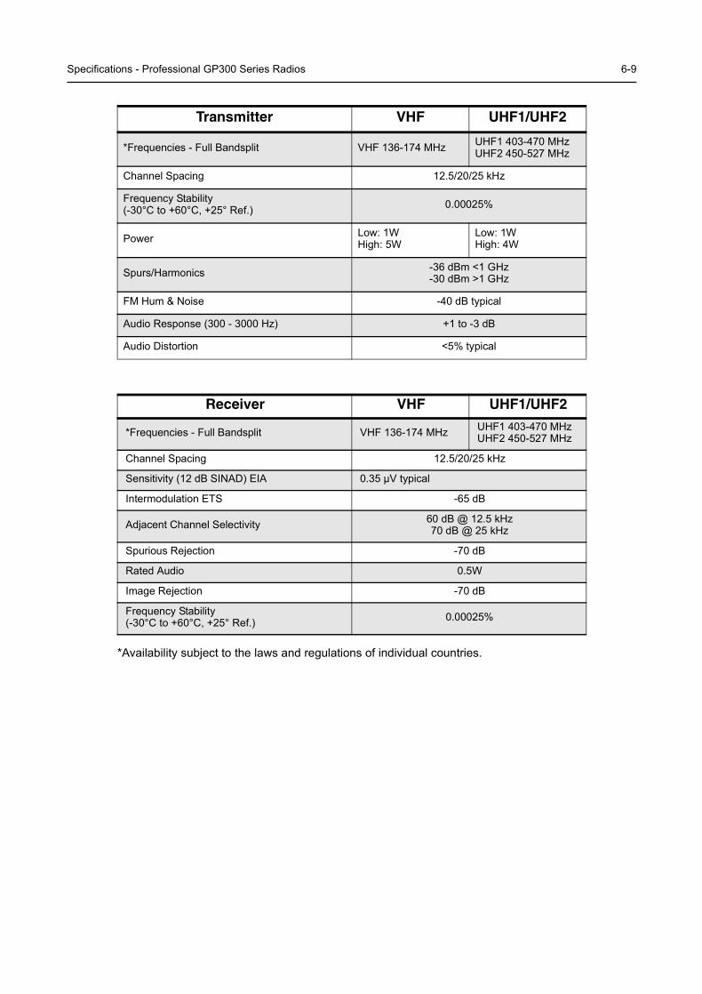
Specifications - Professional GP300 Series Radios 6-9
*Availability subject to the laws and regulations of individual countries.
Transmitter VHF UHF1/UHF2
*Frequencies - Full Bandsplit VHF 136-174 MHz UHF1 403-470 MHzUHF2 450-527 MHz
Channel Spacing 12.5/20/25 kHz
Frequency Stability(-30°C to +60°C, +25° Ref.) 0.00025%
Power Low: 1WHigh: 5W
Low: 1WHigh: 4W
Spurs/Harmonics -36 dBm <1 GHz-30 dBm >1 GHz
FM Hum & Noise -40 dB typical
Audio Response (300 - 3000 Hz) +1 to -3 dB
Audio Distortion <5% typical
Receiver VHF UHF1/UHF2
*Frequencies - Full Bandsplit VHF 136-174 MHz UHF1 403-470 MHzUHF2 450-527 MHz
Channel Spacing 12.5/20/25 kHz
Sensitivity (12 dB SINAD) EIA 0.35 µV typical
Intermodulation ETS -65 dB
Adjacent Channel Selectivity 60 dB @ 12.5 kHz 70 dB @ 25 kHz
Spurious Rejection -70 dB
Rated Audio 0.5W
Image Rejection -70 dB
Frequency Stability(-30°C to +60°C, +25° Ref.) 0.00025%

6-10 MODEL CHART AND TEST SPECIFICATION
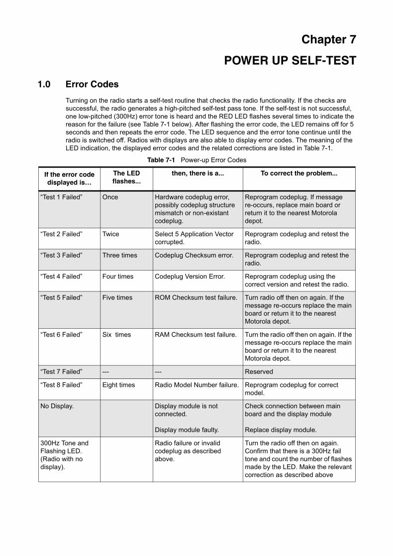
Chapter 7
POWER UP SELF-TEST
1.0 Error Codes
Turning on the radio starts a self-test routine that checks the radio functionality. If the checks are successful, the radio generates a high-pitched self-test pass tone. If the self-test is not successful, one low-pitched (300Hz) error tone is heard and the RED LED flashes several times to indicate the reason for the failure (see Table 7-1 below). After flashing the error code, the LED remains off for 5 seconds and then repeats the error code. The LED sequence and the error tone continue until the radio is switched off. Radios with displays are also able to display error codes. The meaning of the LED indication, the displayed error codes and the related corrections are listed in Table 7-1.
Table 7-1 Power-up Error Codes
If the error code displayed is…
The LED flashes...
then, there is a... To correct the problem...
“Test 1 Failed” Once Hardware codeplug error, possibly codeplug structure mismatch or non-existant codeplug.
Reprogram codeplug. If message re-occurs, replace main board or return it to the nearest Motorola depot.
“Test 2 Failed” Twice Select 5 Application Vector corrupted.
Reprogram codeplug and retest the radio.
“Test 3 Failed” Three times Codeplug Checksum error. Reprogram codeplug and retest the radio.
“Test 4 Failed” Four times Codeplug Version Error. Reprogram codeplug using the correct version and retest the radio.
“Test 5 Failed” Five times ROM Checksum test failure. Turn radio off then on again. If the message re-occurs replace the main board or return it to the nearest Motorola depot.
“Test 6 Failed” Six times RAM Checksum test failure. Turn the radio off then on again. If the message re-occurs replace the main board or return it to the nearest Motorola depot.
“Test 7 Failed” --- --- Reserved
“Test 8 Failed” Eight times Radio Model Number failure. Reprogram codeplug for correct model.
No Display. Display module is not connected.
Display module faulty.
Check connection between main board and the display module
Replace display module.
300Hz Tone and Flashing LED.(Radio with no display).
Radio failure or invalid codeplug as described above.
Turn the radio off then on again. Confirm that there is a 300Hz fail tone and count the number of flashes made by the LED. Make the relevant correction as described above

7-2 POWER UP SELF-TEST