Embed Size (px)
Citation preview

P a g e | 1
Application
Key Features
ZERO Dead Leg between piston face and pipe bore. 60.0°degree Y pattern outlet design minimising change of direction and potential wear problems. Piston face is contoured and sits flush to mimic the internal radius of the pipe. Hard face overlay to piston for greater wear resistance. Crust breaking action to quickly open a flow path in partially impacted systems. Pneumatically actuated configurations preferred for safe operation in remote control situations. Rulon Scrapper seals preventing any paste from entering behind the piston. Simple mounting into overhead reticulation systems. Integral in-built transmitter and discrete read switches within the actuator to know piston position at any time. Valve can be completely disassembled for maintenance and cleaning activities if required. On board flush ports to enhance valve efficiency, sealing longevity and remain blockage free
Globally, underground mining companies using hydraulic and cemented fill type backfill systems are finding the increasing need to install reliable dump valves in their underground paste reticulation systems for safety reasons and for reasons of conveniently dumping flush water and residual paste away from the main stope delivery point. Paste system blockages through solidification are also a key area of frustration for mining companies running paste delivery systems as they typically lead to lengthy downtime and expensive remedial works to clear the blockages for the mining operator. As an emergency / safety device in pipe burst or over-pressurisation situations you also need absolute confidence that the technology you chose will perform on demand and itself not become a point of blockage like alternate dump valve technologies currently on the market. Our Piston valve design has taken into consideration several elements delivering a reliable and very low maintenance instrument saving mining companies globally millions of dollars per year in lost revenue due to downtime and expensive equipment replacement.
P a g e | 2
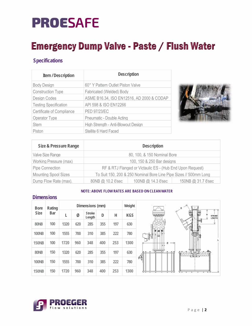
Specifications
Item / Description Description
Body Design 60° Y Pattern Outlet Piston Valve Construction Type Fabricated (Welded) Body Design Codes ASME B16.34, ISO EN12516, AD 2000 & CODAP Testing Specification API 598 & ISO EN12266 Certificate of Compliance PED 97/23/EC Operator Type Pneumatic - Double Acting Stem High Strength - Anti-Blowout Design Piston Stellite 6 Hard Faced
Size & Pressure Range Description
Valve Size Range 80, 100, & 150 Nominal Bore Working Pressure (max) 100, 150 & 250 Bar designs Pipe Connection RF & RTJ Flanged or Victaulic ES - (Hub End Upon Request) Mounting Spool Sizes To Suit 150, 200 & 250 Nominal Bore Line Pipe Sizes // 500mm Long Dump Flow Rate (max). 80NB @ 10.2 ℓ/sec 100NB @ 14.3 ℓ/sec 150NB @ 31.7 ℓ/sec
NOTE: ABOVE FLOW RATES ARE BASED ON CLEAN WATER
Dimensions
Bore Size
Rating Bar
Dimensions (mm) Weight
L Ø Stroke Length D H KGS
80NB 100 1320 620 285 355 197 630
100NB 100 1555 700 310 385 222 780
150NB 100 1720 960 348 400 253 1300
80NB 150 1320 620 285 355 197 630
100NB 150 1555 700 310 385 222 780
150NB 150 1720 960 348 400 253 1300
P a g e | 3
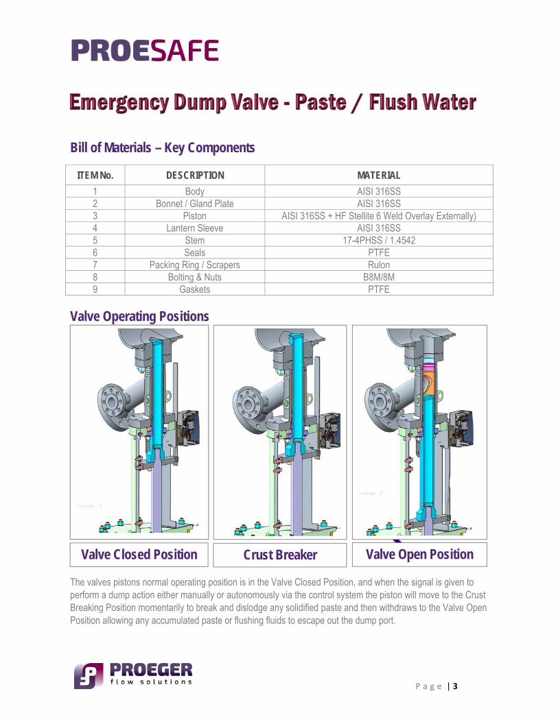
Bill of Materials – Key Components
ITEM No. DESCRIPTION MATERIAL
1 Body AISI 316SS 2 Bonnet / Gland Plate AISI 316SS 3 Piston AISI 316SS + HF Stellite 6 Weld Overlay Externally) 4 Lantern Sleeve AISI 316SS 5 Stem 17-4PHSS / 1.4542 6 Seals PTFE 7 Packing Ring / Scrapers Rulon 8 Bolting & Nuts B8M/8M 9 Gaskets PTFE
Valve Operating Positions
The valves pistons normal operating position is in the Valve Closed Position, and when the signal is given to perform a dump action either manually or autonomously via the control system the piston will move to the Crust Breaking Position momentarily to break and dislodge any solidified paste and then withdraws to the Valve Open Position allowing any accumulated paste or flushing fluids to escape out the dump port.
Valve Open Position Valve Closed Position Crust Breaker
P a g e | 4
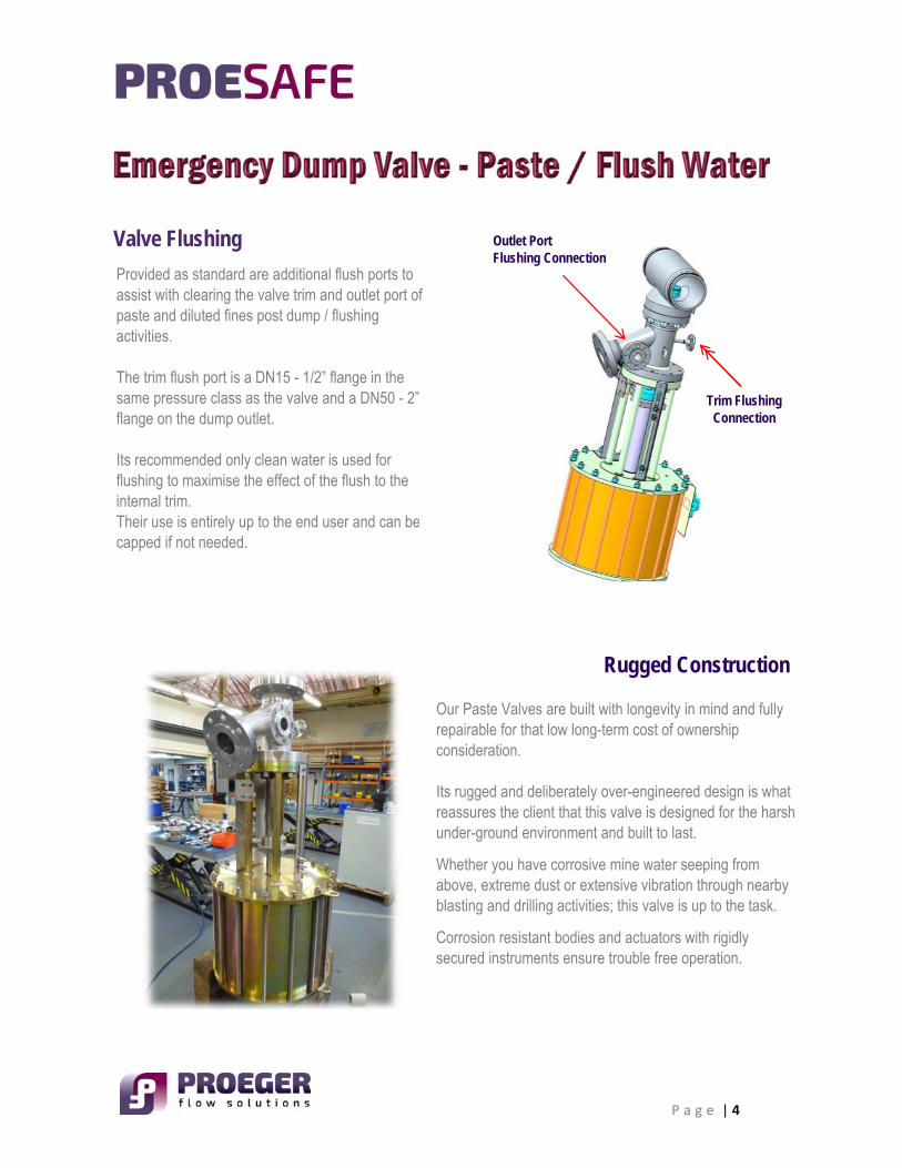
Valve Flushing
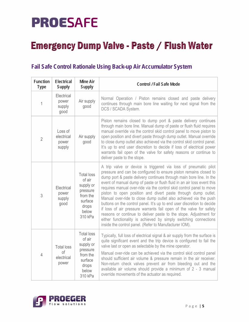
Rugged Construction
Provided as standard are additional flush ports to assist with clearing the valve trim and outlet port of paste and diluted fines post dump / flushing activities. The trim flush port is a DN15 - 1/2” flange in the same pressure class as the valve and a DN50 - 2” flange on the dump outlet. Its recommended only clean water is used for flushing to maximise the effect of the flush to the internal trim. Their use is entirely up to the end user and can be capped if not needed.
Outlet Port Flushing Connection
Trim Flushing Connection
Our Paste Valves are built with longevity in mind and fully repairable for that low long-term cost of ownership consideration. Its rugged and deliberately over-engineered design is what reassures the client that this valve is designed for the harsh under-ground environment and built to last.
Whether you have corrosive mine water seeping from above, extreme dust or extensive vibration through nearby blasting and drilling activities; this valve is up to the task.
Corrosion resistant bodies and actuators with rigidly secured instruments ensure trouble free operation.
P a g e | 5
Fail Safe Control Rationale Using Back-up Air Accumulator System Function
Type Electrical
Supply Mine Air Supply
Control / Fail Safe Mode
1
Electrical power supply good
Air supply good
Normal Operation / Piston remains closed and paste delivery continues through main bore line waiting for next signal from the DCS / SCADA System.
2
Loss of electrical
power supply
Air supply good
Piston remains closed to dump port & paste delivery continues through main bore line. Manual dump of paste or flush fluid requires manual override via the control skid control panel to move piston to open position and divert paste through dump outlet. Manual override to close dump outlet also achieved via the control skid control panel. It’s up to end user discretion to decide if loss of electrical power warrants fail open of the valve for safety reasons or continue to deliver paste to the stope.
3
Electrical power supply good
Total loss of air
supply or pressure from the surface drops below
310 kPa
A trip valve or device is triggered via loss of pneumatic pilot pressure and can be configured to ensure piston remains closed to dump port & paste delivery continues through main bore line. In the event of manual dump of paste or flush fluid in an air loss event this requires manual over-ride via the control skid control panel to move piston to open position and divert paste through dump outlet. Manual over-ride to close dump outlet also achieved via the push buttons on the control panel. It’s up to end user discretion to decide if loss of air pressure warrants fail open of the valve for safety reasons or continue to deliver paste to the stope. Adjustment for either functionality is achieved by simply switching connections inside the control panel. (Refer to Manufacturer IOM).
4
Total loss of
electrical power
Total loss of air
supply or pressure from the surface drops below
310 kPa
Typically, full loss of electrical signal & air supply from the surface is quite significant event and the trip device is configured to fail the valve last or open as selectable by the mine operator.
Manual over-ride can be achieved via the control skid control panel should sufficient air volume & pressure remain in the air receiver. Non-return check valves prevent air from bleeding out and the available air volume should provide a minimum of 2 - 3 manual override movements of the actuator as required.
P a g e | 6
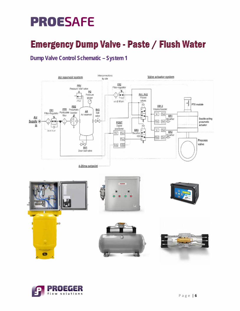
Dump Valve Control Schematic – System 1
P a g e | 7
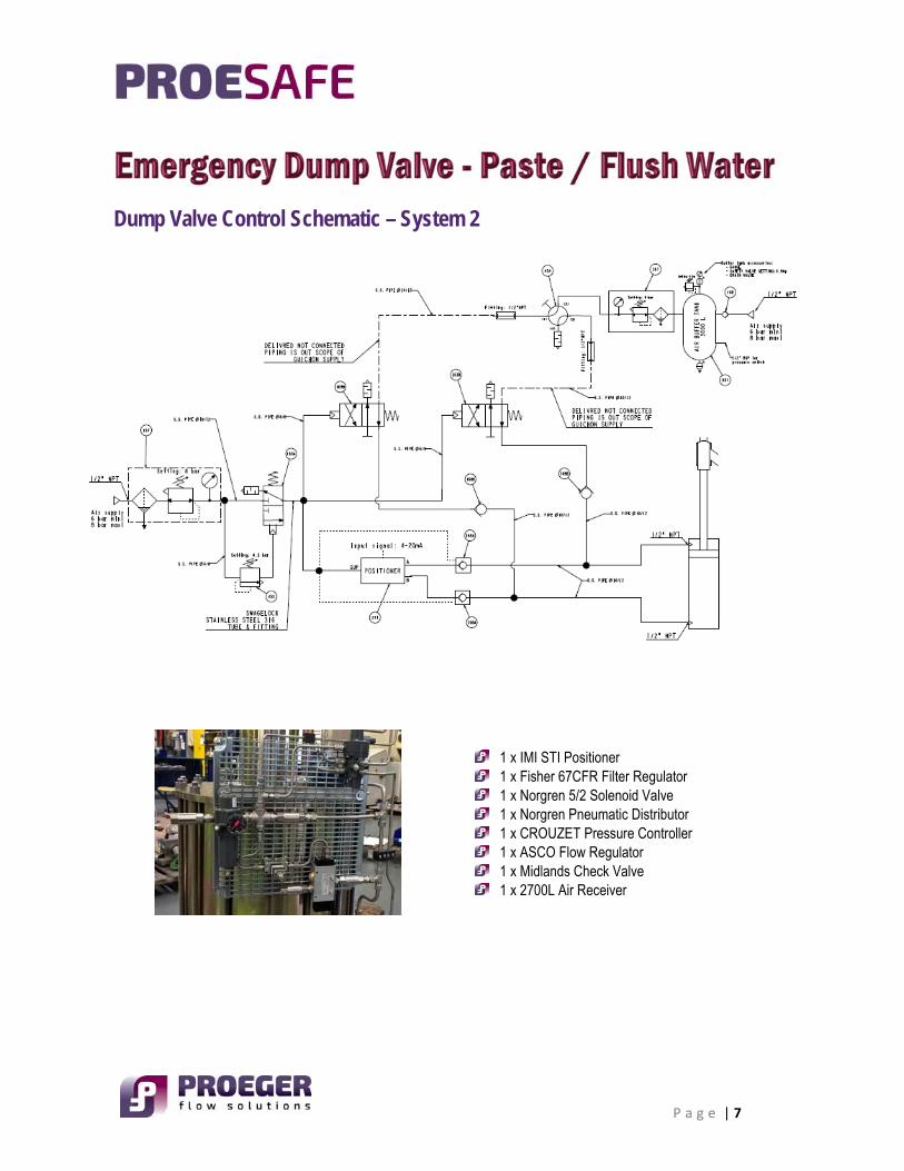
Dump Valve Control Schematic – System 2
1 x IMI STI Positioner 1 x Fisher 67CFR Filter Regulator 1 x Norgren 5/2 Solenoid Valve 1 x Norgren Pneumatic Distributor 1 x CROUZET Pressure Controller 1 x ASCO Flow Regulator 1 x Midlands Check Valve 1 x 2700L Air Receiver
P a g e | 8
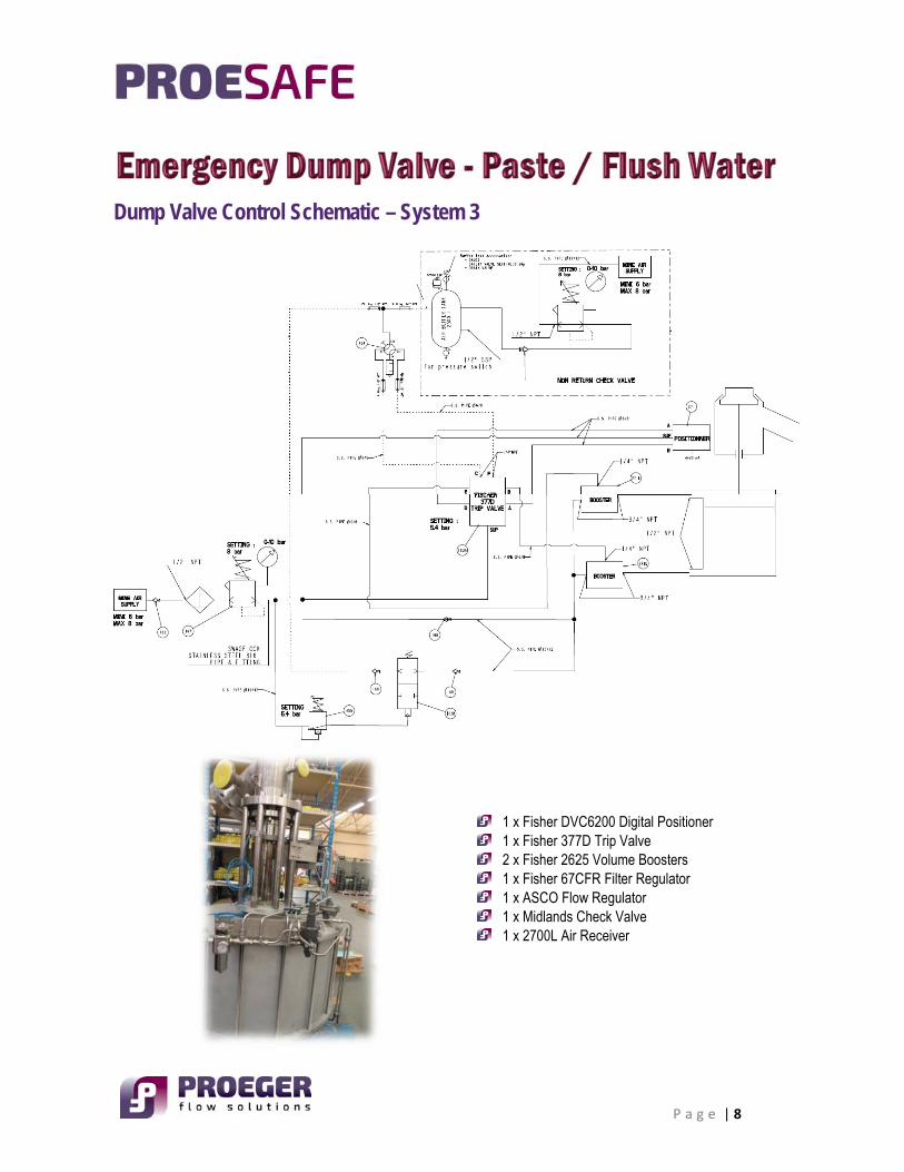
Dump Valve Control Schematic – System 3
1 x Fisher DVC6200 Digital Positioner 1 x Fisher 377D Trip Valve 2 x Fisher 2625 Volume Boosters 1 x Fisher 67CFR Filter Regulator 1 x ASCO Flow Regulator 1 x Midlands Check Valve 1 x 2700L Air Receiver
P a g e | 9
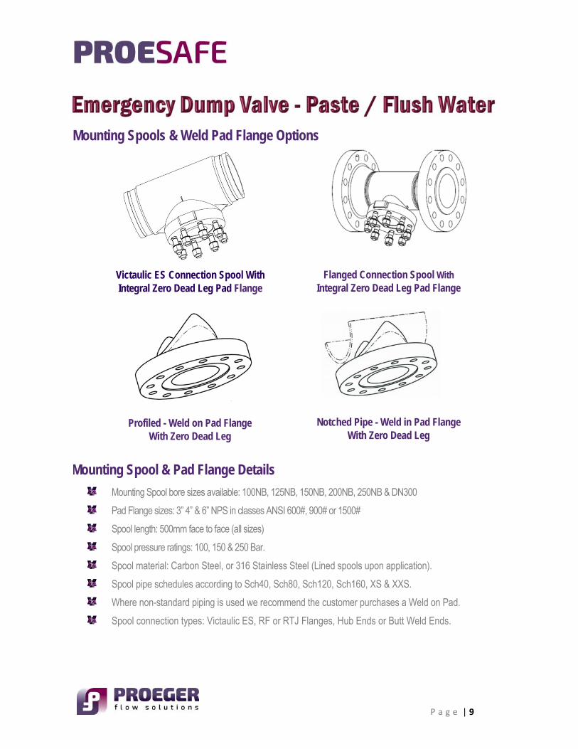
Mounting Spools & Weld Pad Flange Options
Mounting Spool & Pad Flange Details
Mounting Spool bore sizes available: 100NB, 125NB, 150NB, 200NB, 250NB & DN300
Pad Flange sizes: 3” 4” & 6” NPS in classes ANSI 600#, 900# or 1500#
Spool length: 500mm face to face (all sizes)
Spool pressure ratings: 100, 150 & 250 Bar.
Spool material: Carbon Steel, or 316 Stainless Steel (Lined spools upon application).
Spool pipe schedules according to Sch40, Sch80, Sch120, Sch160, XS & XXS.
Where non-standard piping is used we recommend the customer purchases a Weld on Pad.
Spool connection types: Victaulic ES, RF or RTJ Flanges, Hub Ends or Butt Weld Ends.
Victaulic ES Connection Spool With Integral Zero Dead Leg Pad Flange
Flanged Connection Spool With Integral Zero Dead Leg Pad Flange
Notched Pipe - Weld in Pad Flange With Zero Dead Leg
Profiled - Weld on Pad Flange With Zero Dead Leg

P a g e | 10
Additional Control System Accessories & Services Available
Air Receiver Volume Tanks – 700 Litres and 3000 Litres to AS1210 Class 3 & CODAP 2010 Cat. B 2b – f 1
Remote Mounted Pneumatic Manual Override Control Boxes
Customised Electronic Paste Valve SCADA Control Systems
Global Mechanical & Electrical Site Commissioning Services
Global End User Training Services
Emergency Dump Valve SCADA Control System
Air Receiver / Volume Tanks 700L to 3000L Available
Remote Mount Manual Override Control Panel
P a g e | 11
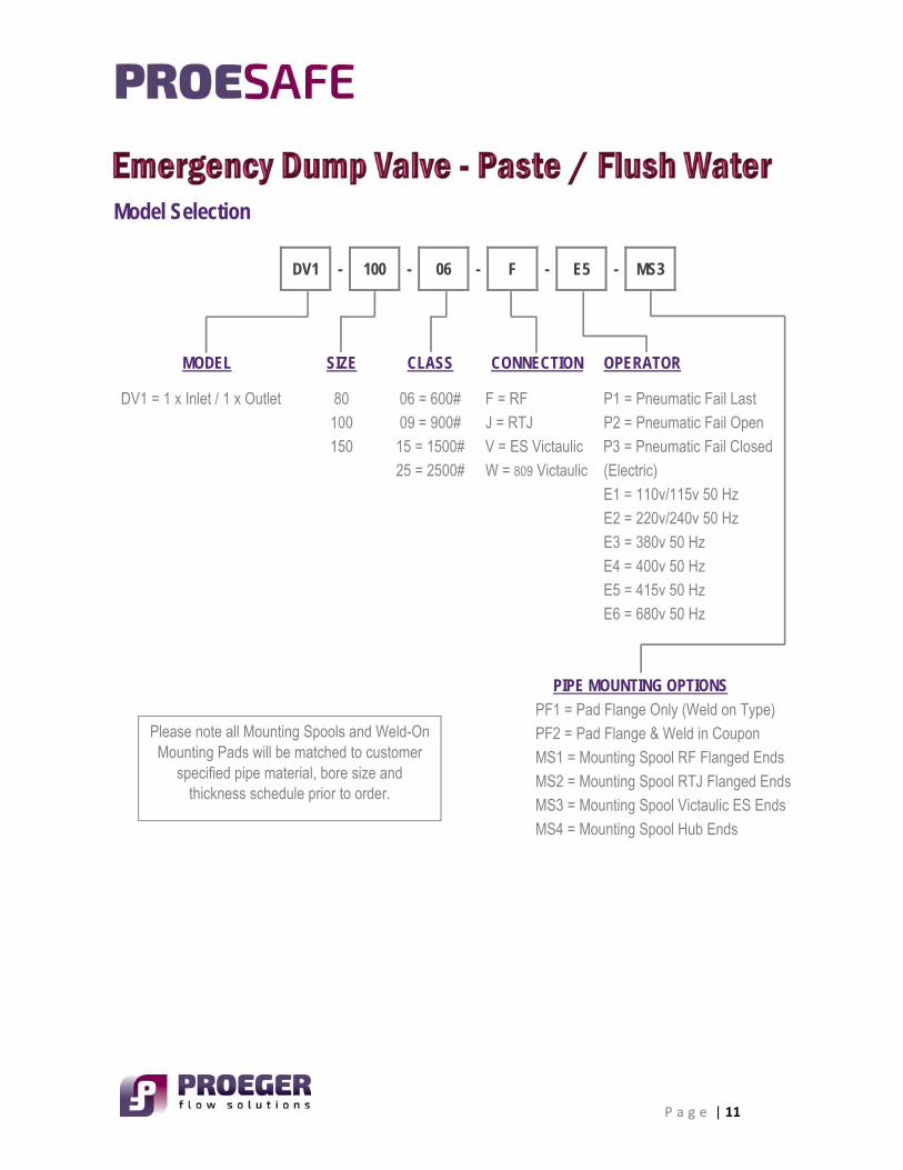
Model Selection
DV1 - 100 - 06 - F - E5 - MS3
MODEL SIZE CLASS CONNECTION OPERATOR
DV1 = 1 x Inlet / 1 x Outlet 80 06 = 600# F = RF P1 = Pneumatic Fail Last
100 09 = 900# J = RTJ P2 = Pneumatic Fail Open 150 15 = 1500# V = ES Victaulic P3 = Pneumatic Fail Closed
25 = 2500# W = 809 Victaulic (Electric)
E1 = 110v/115v 50 Hz
E2 = 220v/240v 50 Hz
E3 = 380v 50 Hz
E4 = 400v 50 Hz E5 = 415v 50 Hz
E6 = 680v 50 Hz
PIPE MOUNTING OPTIONS
PF1 = Pad Flange Only (Weld on Type) PF2 = Pad Flange & Weld in Coupon
MS1 = Mounting Spool RF Flanged Ends
MS2 = Mounting Spool RTJ Flanged Ends MS3 = Mounting Spool Victaulic ES Ends
MS4 = Mounting Spool Hub Ends
Please note all Mounting Spools and Weld-On Mounting Pads will be matched to customer
specified pipe material, bore size and thickness schedule prior to order.

P a g e | 12
Contact Details
Sales Office – 9 Quandong Street, Meridan Plains Queensland 4551
T: +61 7 5438 8255 | M: +61 (0)418 606 255 E: [email protected]
W: www.proegerflowsolutions.com