Embed Size (px)
Citation preview
Products Catalog Flame Monitoring& Evaluation Systems
Flame Scanners – System 3000
Flame Amplifiers – System 3000
Compact Flame Controller – CFC x000
Network Solution for CFC x000
Functional Upgrades of CFC x000
CFC x000 in OE-Converter Wide Housing
Software for CFC x000
Compact Flame Controller – CFC 200
Compact Flame Controller – CFC 100
Power Supply Units
Flame Evaluation & Ionisation Flame Amplifier
Accessories
Measurement and Test Devices
Fiber Optic Technologies
Special Fiber Optic Solutions
Housings and Racks
4
6
8
10
11
11
12
14
16
17
18
20
22
23
25
26
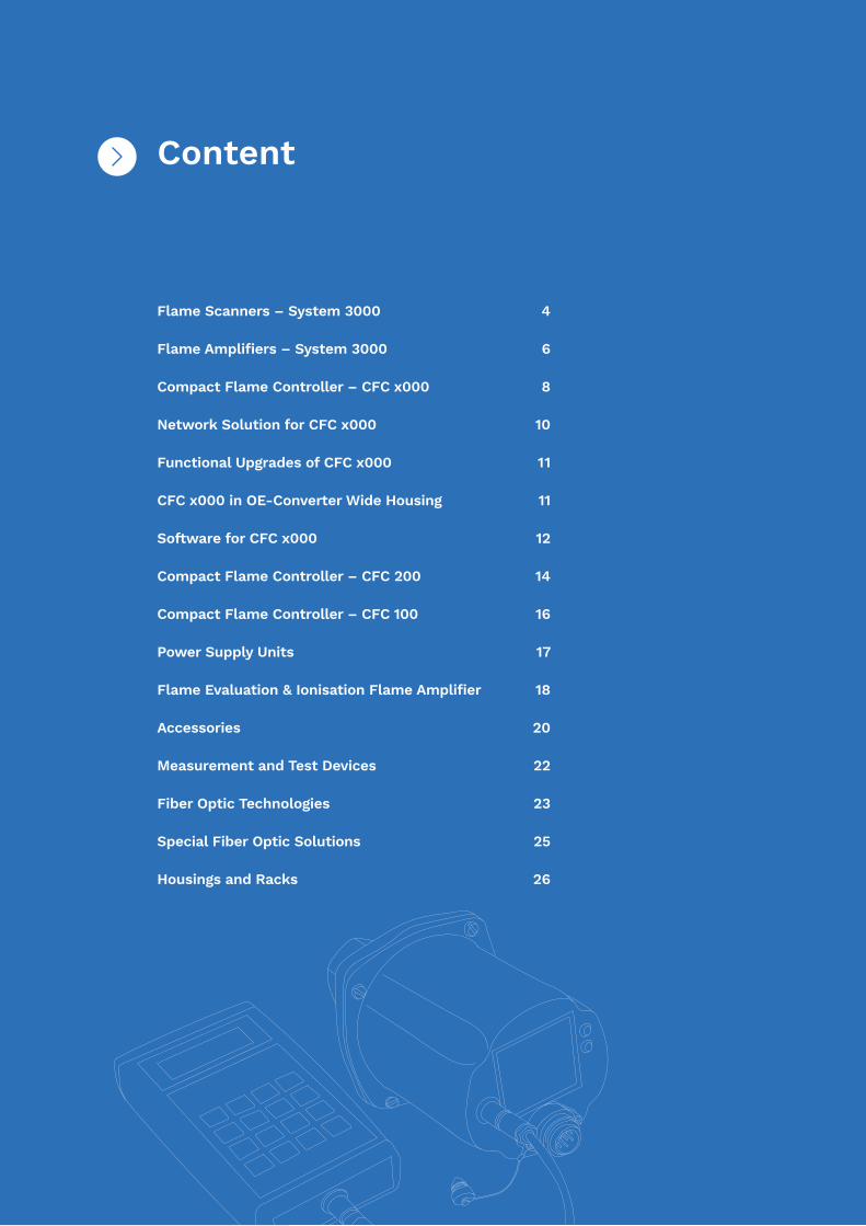
Content

The growing demands for safety and the increasing importance of environmental protection present new challenges for industrial companies. The Flamonitec®
product range offers the right flame monitoring system with all relevant safety certificates for every combustion process.
Through their maximum quality and over-fulfilment of sa-fety standards, Flamonitec® products help to meet the-se challenges appropriately. A good example is that our Flamonitec® System 3000 has already met today’s safety requirements according to SIL3 for 30 years.
More than 20 patents in the field of flame monitoring show what the Mindermann Group understands by innovation. The entire spectrum of flame monitoring is covered, from basic research to processes and electronic circuits.
We preserve values and create sustainable innovations!
Since 2017, the Mindermann Group is operating from its new facility in Heiligenhaus, Germany.
The family-owned company, now in its second genera-tion, was founded in Ratingen in 1973 and has set decisive milestones in optical flame monitoring in its now almost 50-year history.
BFI Automation Mindermann GmbH offers solutions for industrial flame monitoring. Through close cooperation and continuous exchange with our customers, we are always developing new systems and forward-looking technolo-gies. This has made BFI Automation Mindermann GmbH a market leader in the field of flame monitoring with repre-sentatives in over 20 countries worldwide.
Together with its sister company BST Solutions GmbH, BFI Automation Mindermann GmbH forms the Minder-mann Group. By bundling the activities of both the com-panies under the brand name Flamonitec®, we have created the world‘s largest supply portfolio for flame monitoring systems for our customers, from heating technology to industrial firing systems and large-scale power plants. Reliable, safe and technologically at the highest level – this is what the Flamonitec® brand stands for – worldwide!
The company – Who we are
ABOUT BFI AUTOMATION MINDERMANN
The name BFI Automation stands for innovative, trendsetting and future-oriented technology.
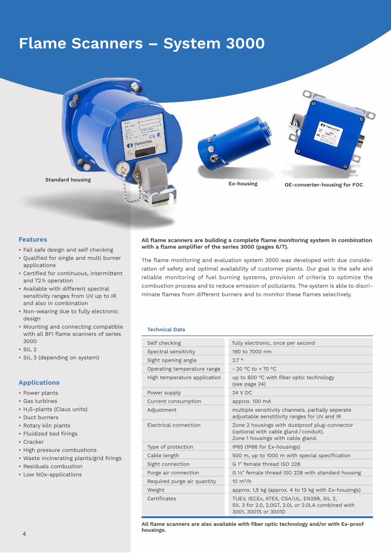
All flame scanners are building a complete flame monitoring system in combination with a flame amplifier of the series 3000 (pages 6/7).
The flame monitoring and evaluation system 3000 was developed with due conside-ration of safety and optimal availability of customer plants. Our goal is the safe and reliable monitoring of fuel burning systems, provision of criteria to optimize the combustion process and to reduce emission of pollutants. The system is able to discri-minate flames from different burners and to monitor these flames selectively.
Technical Data
Self checking fully electronic, once per secondSpectral sensitivity 190 to 7000 nmSight opening angle 2.7 °Operating temperature range - 20 °C to + 70 °CHigh temperature application up to 600 °C with fiber optic technology
(see page 24)Power supply 24 V DCCurrent consumption approx. 100 mAAdjustment multiple sensitivity channels, partially seperate
adjustable senstitivity ranges for UV and IRElectrical connection Zone 2 housings with dustproof plug-connector
(optional with cable gland / conduit).Zone 1 housings with cable gland.
Type of protection IP65 (IP66 for Ex-housings)Cable length 500 m, up to 1000 m with special specificationSight connection G 1" female thread ISO 228Purge air connection G ½" female thread ISO 228 with standard housingRequired purge air quantity 10 m³/hWeight approx. 1,5 kg (approx. 4 to 13 kg with Ex-housings)Certificates TUEV, IECEx, ATEX, CSA/UL, EN298, SIL 2,
SIL 3 for 2.0, 2.0GT, 2.0L or 2.0LA combined with 3001, 3001S or 3001D
Features• Fail safe design and self checking• Qualified for single and multi burner
applications• Certified for continuous, intermittent
and 72 h operation• Available with different spectral
sensitivity ranges from UV up to IR and also in combination
• Non-wearing due to fully electronic design
• Mounting and connecting compatible with all BFI flame scanners of series 3000
• SIL 2• SIL 3 (depending on system)
Applications• Power plants• Gas turbines• H2S-plants (Claus units)• Duct burners• Rotary kiln plants• Fluidized bed firings• Cracker• High pressure combustions• Waste incinerating plants/grid firings• Residuals combustion• Low NOx-applications
Ex-housing OE-converter-housing for FOCStandard housing
All flame scanners are also available with fiber optic technology and/or with Ex-proof housings.
4
Flame Scanners – System 3000
Fuels• Oil (LDO & HFO)• Natural gas, blast furnace gas and
coke oven gas• Biomass/biogas• Powdered coal• Sulfur• Naphtha• H2S• H2
• NH3
Accessories• Swivel mount• Ball valve• Heating insulator• Pressure barrier• Measuring adapter• Signal generator• Special cable• Alignment tool• Heating• Tropicalization
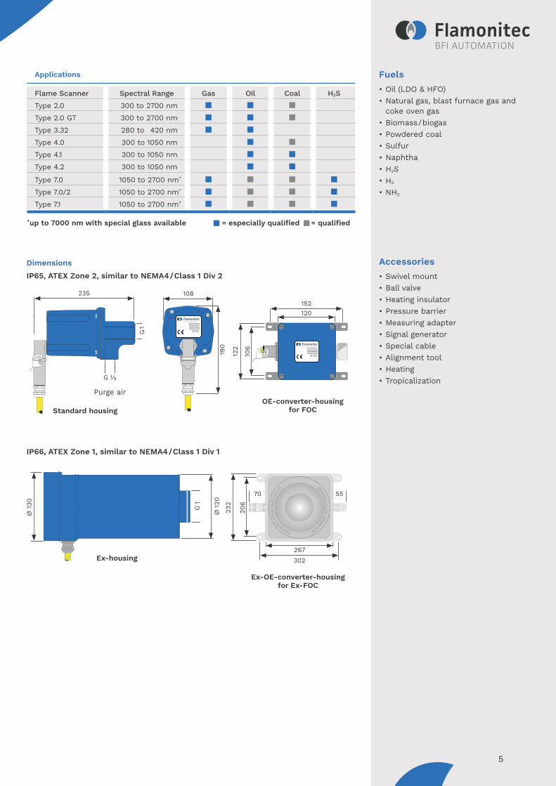
Applications
Flame Scanner Spectral Range Gas Oil Coal H2SType 2.0 300 to 2700 nm Type 2.0 GT 300 to 2700 nm Type 3.32 280 to 420 nmType 4.0 300 to 1050 nmType 4.1 300 to 1050 nmType 4.2 300 to 1050 nm
Type 7.0 1050 to 2700 nm*
Type 7.0/2 1050 to 2700 nm*
Type 7.1 1050 to 2700 nm*
*up to 7000 nm with special glass available = especially qualified = qualified
267302
206
232
5570
∅ 1
20
∅ 1
30 G 1
24 V DC
24 V DC24 V DC
108
190
Purge air
235
G 1
G 1/2
120
106
122
152
Dimensions
IP66, ATEX Zone 1, similar to NEMA4/Class 1 Div 1
IP65, ATEX Zone 2, similar to NEMA4/Class 1 Div 2
OE-converter-housing for FOC
Ex-OE-converter-housing for Ex-FOC
Ex-housing
Standard housing
5

All flame amplifiers are building a complete flame monitoring system in combination with a flame scanner of series 3000 (pages 4/5).
The flame monitoring and evaluation system 3000 is based on different flame amplifier modules, manufactured as 19"-slide-in modules. They contain all control logics and provide the signals for external processing.The flame monitoring and evaluation system 3000 was developed with due consideration of safety and optimal availability of customer plant. The goal is the safe andreliable monitoring of fuel burning systems, provision of criteria to optimize the com-bustion process and to reduce emission of pollutants. The system is able to discriminate flames from different burners and to monitor these flames selectively.
Technical Data
Self checking fully electronic, once per secondFlame intensity output 0/4 to 20 mARelay output 1 safety change-over-contact, internally fused 1A
1 auxiliary change-over-contact (3001/3001D/3001S/ 3016), 1 failure alarm (3016)
Power supply 24 V DCCurrent consumption approx. 300 mA (3001, 3001D, 3001S, 3016)Operating temperature range - 20 °C to + 70 °C (3001, 3001D, 3001S)
0 °C to + 60 °C (3016)
Cable lenght 500 m, up to 1000 m with special specificationSafety fail safe design, self checkingMode of operation continuousWeight see 'Technical features' on next pageType of protection IP00Safety switch OFF time selectable 1 to 6 s (3001, 3001D, 3001S)
selectable 200 to 650 ms (3016)
Certificates TUEV, CSA, UL, EN298, SIL 2, SIL 3 for 3001, 3001S/ 3001D combined with 2.0, 2.0GT, 2.0L or 2.0LA
Features• Fail safe design and self checking• Selective monitoring of different
flames• Certified for continuous, intermittent
and 72 h operation• Optimization of combustion process• Multiple sensitivity ranges and
switch-off times, selectable by remote signal
• Parallel connection of multiple flame scanners (scanner redundancy)
• 19-inch design in accordance with international standards
• SIL 2• SIL 3 (depending on system)
Applications• Power plants• Gas turbines• H2S-plants (Claus units)• Duct burners• Rotary kiln plants• Fluidized bed firings• Cracker• High pressure combustions• Waste incinerating plants/grid firings• Combustion of residuals• Low NOx-applications
Type 3001 Type 3001D Type 3016
All flame amplifiers are also available in Ex-housings. See chapter 'Housings'on pages 26/27.
Type 3001S
6
Flame Amplifiers – System 3000
Technical Data
Self checking fully electronic, once per secondFlame intensity output 0/4 to 20 mARelay output 1 safety change-over-contact, internally fused 1A
1 auxiliary change-over-contact (3001/3001D/3001S/ 3016), 1 failure alarm (3016)
Power supply 24 V DCCurrent consumption approx. 300 mA (3001, 3001D, 3001S, 3016)Operating temperature range - 20 °C to + 70 °C (3001, 3001D, 3001S)
0 °C to + 60 °C (3016)
Cable lenght 500 m, up to 1000 m with special specificationSafety fail safe design, self checkingMode of operation continuousWeight see 'Technical features' on next pageType of protection IP00Safety switch OFF time selectable 1 to 6 s (3001, 3001D, 3001S)
selectable 200 to 650 ms (3016)
Certificates TUEV, CSA, UL, EN298, SIL 2, SIL 3 for 3001, 3001S/ 3001D combined with 2.0, 2.0GT, 2.0L or 2.0LA
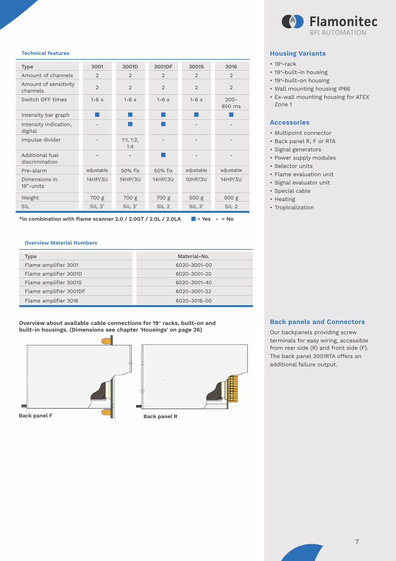
Housing Variants• 19"-rack• 19"-built-in housing• 19"-built-on housing• Wall mounting housing IP66• Ex-wall mounting housing for ATEX
Zone 1
Accessories• Multipoint connector• Back panel R, F or RTA• Signal generators• Power supply modules• Selector units• Flame evaluation unit• Signal evaluator unit• Special cable• Heating• Tropicalization
Back panels and ConnectorsOur backpanels providing screwterminals for easy wiring, accessible from rear side (R) and front side (F).The back panel 3001RTA offers anadditional failure output.
Technical features
Type 3001 3001D 3001DF 3001S 3016Amount of channels 2 2 2 2 2Amount of sensitivity channels 2 2 2 2 2
Switch OFF times 1-6 s 1-6 s 1-6 s 1-6 s 200-650 ms
Intensity bar graph
Intensity indication, digital
- - -
Impulse divider - 1:1, 1:2, 1:4
- - -
Additional fuel discrimination
- - - -
Pre-alarm adjustable 50% fix 50% fix adjustable adjustable
Dimensions in 19"-units
14HP/3U 14HP/3U 14HP/3U 10HP/3U 14HP/3U
Weight 700 g 700 g 700 g 500 g 500 gSIL SIL 3* SIL 3* SIL 2 SIL 3* SIL 2
Overview Material Numbers
Type Material-No.Flame amplifier 3001 6020-3001-00Flame amplifier 3001D 6020-3001-20Flame amplifier 3001S 6020-3001-40Flame amplifier 3001DF 6020-3001-22
Flame amplifier 3016 6020-3016-00
*in combination with flame scanner 2.0 / 2.0GT / 2.0L / 2.0LA = Yes - = No
Overview about available cable connections for 19" racks, built-on and built-in housings. (Dimensions see chapter 'Housings' on page 26)
Back panel F Back panel R
7
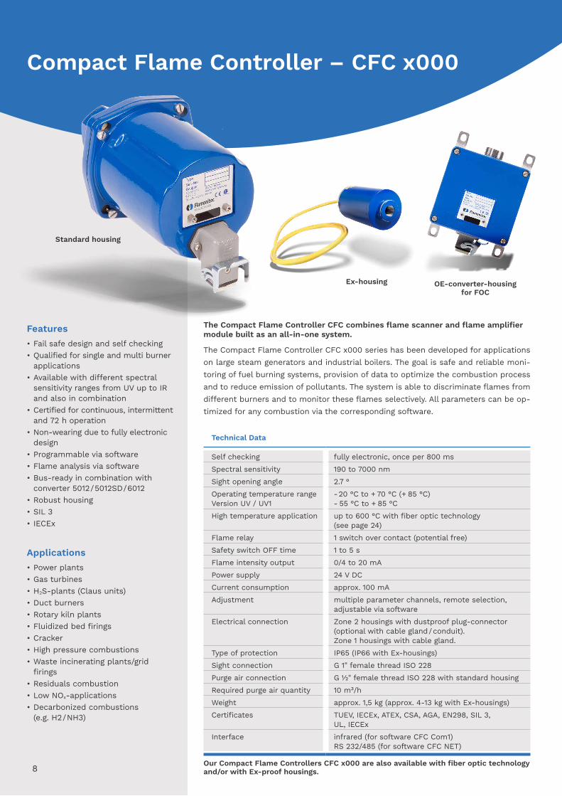
The Compact Flame Controller CFC combines flame scanner and flame amplifier module built as an all-in-one system.
The Compact Flame Controller CFC x000 series has been developed for applications on large steam generators and industrial boilers. The goal is safe and reliable moni-toring of fuel burning systems, provision of data to optimize the combustion process and to reduce emission of pollutants. The system is able to discriminate flames from different burners and to monitor these flames selectively. All parameters can be op-timized for any combustion via the corresponding software.
Technical Data
Self checking fully electronic, once per 800 msSpectral sensitivity 190 to 7000 nmSight opening angle 2.7 ° Operating temperature range Version UV / UV1
- 20 °C to + 70 °C (+ 85 °C)- 55 °C to + 85 °C
High temperature application up to 600 °C with fiber optic technology (see page 24)
Flame relay 1 switch over contact (potential free)Safety switch OFF time 1 to 5 sFlame intensity output 0/4 to 20 mAPower supply 24 V DCCurrent consumption approx. 100 mAAdjustment multiple parameter channels, remote selection,
adjustable via softwareElectrical connection Zone 2 housings with dustproof plug-connector
(optional with cable gland / conduit).Zone 1 housings with cable gland.
Type of protection IP65 (IP66 with Ex-housings)Sight connection G 1" female thread ISO 228Purge air connection G ½" female thread ISO 228 with standard housingRequired purge air quantity 10 m³/hWeight approx. 1,5 kg (approx. 4-13 kg with Ex-housings)Certificates TUEV, IECEx, ATEX, CSA, AGA, EN298, SIL 3,
UL, IECExInterface infrared (for software CFC Com1)
RS 232/485 (for software CFC NET)
Features• Fail safe design and self checking• Qualified for single and multi burner
applications• Available with different spectral
sensitivity ranges from UV up to IR and also in combination
• Certified for continuous, intermittent and 72 h operation
• Non-wearing due to fully electronic design
• Programmable via software• Flame analysis via software• Bus-ready in combination with
converter 5012/5012SD/6012• Robust housing• SIL 3• IECEx
Applications• Power plants• Gas turbines• H2S-plants (Claus units)• Duct burners• Rotary kiln plants• Fluidized bed firings• Cracker• High pressure combustions• Waste incinerating plants/grid
firings• Residuals combustion• Low NOx-applications• Decarbonized combustions (e.g. H2/NH3)
Ex-housing OE-converter-housing for FOC
Our Compact Flame Controllers CFC x000 are also available with fiber optic technology and/or with Ex-proof housings.8
Compact Flame Controller – CFC x000
Standard housing

9 = Function available
CFC-Configuration
Function CFC 1000
CFC 2000
CFC 3000
CFC 4000
Multiple (2/4) parameter channel, remote selection
Frequency analysis via softwareDC-rough signal evaluation via softwareRS 232 interface, network ready with converter 5012 (uni-directional)
RS 232 interface, network ready withconverter 6012 (bi-directional)
Failure output
Fuels• Oil (LDO & HFO)• Natural gas, blast furnace gas
and coke oven gas• Biomass/biogas• Powdered coal• Sulphur• Naphtha• H2S• H2
• NH3
Accessories• Swivel mount• Ball valve• Heating insulator• Pressure barrier• Signal generator• Special cable• Alignment tool• Heating• Tropicalization• Power supply• Adapter unit• Converter 5012/6012 • Software• CFC Com 1 / NET / TAB
Applications
CFC Type
Spectral Range
Spectral Sensitivity
Gas Oil Coal H2S Bio H2
CFC x000UV UV 280 to 420 nmCFC x000UV1 UV/VIS 190 to 550 nmCFC x000IR UV/IR 300 to 1050 nmCFC x000IR1* IR 1050 to 2700 nm
(7000 nm)CFC x000IR2 UV/IR 300 to 2700 nmCFC x000IR3 IR 1050 to 2700 nm
*not available for CFC 1000 = especially qualified = qualified
9
267302
206
232
5570
∅ 1
20
G 1
22363
24 V DC
24 V DC
108
190
Purge air
24 V DC
235
G 1
G 1/2
106
122
152120
Dimensions
IP66, ATEX Zone 1, similar to NEMA4/Class 1 Div 1 *The Ex-housing is also available in V4A stainless steel
IP65, ATEX Zone 2, similar to NEMA4/Class 1 Div 2
OE-converter-housing for FOC
Ex-OE-converter-housing for Ex-FOC
Ex-housing
Standard housing
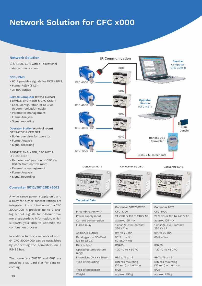
Converter 5012/5012SD/6012
A wide range power supply unit and a relay for higher contact ratings are integrated. In combination with a CFC 3000/4000 it provides up to 3 ana-log output signals for different fla-me characteristic information, which supports your DCS to optimize the combustion process.
In addition to this, a network of up to 64 CFC 3000/4000 can be established by connecting the converters on a RS485 bus.
The converters 5012SD and 6012 are providing a SD-Card slot for data re-cording.
Network Solution
CFC 4000 / 6012 with bi-directional data communication: DCS / BMS• 6012 provides signals for DCS / BMS:• Flame Relay (SIL3)• 3x mA output Service Computer (at the burner) SERVICE ENGINEER & CFC COM 1• Local configuration of CFC via IR communication cable • Parameter management• Flame Analysis• Signal recording Operator Station (control room) OPERATOR & CFC NET• Boiler overview for operator• Flame Analysis• Signal recording SERVICE ENGINEER, CFC NET & USB DONGLE• Remote configuration of CFC via RS485 from control room• Parameter management• Flame Analysis• Signal Recording
10
Technical Data
Converter 5012/5012SD Converter 6012In combination with CFC 3000 CFC 4000Power supply input 24 V DC or 100 to 240 V AC 24 V DC or 100 to 240 V ACCurrent consumption approx. 125 mA approx. 125 mAFlame relay 1 change-over-contact
250 V/1 A1 change-over-contact 250 V/ 1 A
Analogue output 0/4 to 20 mA 0/4 to 20 mADatalogger on SD-Card(up to 32 GB)
5012 = No5012SD = Yes
6012 = Yes
Data output RS485 RS485Operating temperature range
- 20 °C to + 60 °C - 20 °C to + 60 °C
Dimensions (W x H x D) mm 99,7 x 75 x 115 99,7 x 75 x 115Type of mounting DIN rail mounting
(35 mm) or built-onDIN rail mounting(35 mm) or built-on
Type of protection IP20 IP20Weight approx. 450 g approx. 450 g
Converter 5012 Converter 5012SD Converter 6012
Network Solution for CFC x000
IR Communication
Operator Station
(CFC NET)
USB Dongle
RS485 / bi-directional
6012
CFC 4000
6012
CFC 4000
6012
CFC 4000
6012
CFC 4000
RS485 / USBConverter
Service Computer
(CFC COM 1)
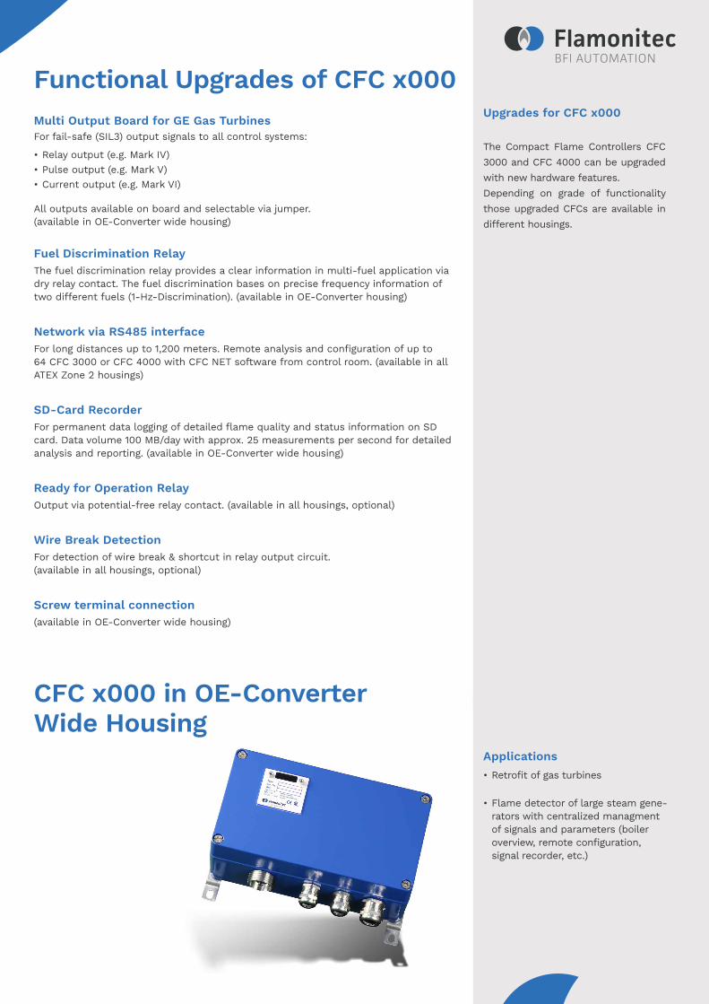
Upgrades for CFC x000
The Compact Flame Controllers CFC 3000 and CFC 4000 can be upgraded with new hardware features. Depending on grade of functionality those upgraded CFCs are available in different housings.
Applications• Retrofit of gas turbines
• Flame detector of large steam gene- rators with centralized managment of signals and parameters (boiler overview, remote configuration, signal recorder, etc.)
Functional Upgrades of CFC x000Multi Output Board for GE Gas Turbines For fail-safe (SIL3) output signals to all control systems:
• Relay output (e.g. Mark IV)• Pulse output (e.g. Mark V)• Current output (e.g. Mark VI)
All outputs available on board and selectable via jumper.(available in OE-Converter wide housing)
Fuel Discrimination RelayThe fuel discrimination relay provides a clear information in multi-fuel application via dry relay contact. The fuel discrimination bases on precise frequency information of two different fuels (1-Hz-Discrimination). (available in OE-Converter housing)
Network via RS485 interfaceFor long distances up to 1,200 meters. Remote analysis and configuration of up to 64 CFC 3000 or CFC 4000 with CFC NET software from control room. (available in all ATEX Zone 2 housings)
SD-Card RecorderFor permanent data logging of detailed flame quality and status information on SD card. Data volume 100 MB/day with approx. 25 measurements per second for detailed analysis and reporting. (available in OE-Converter wide housing)
Ready for Operation Relay Output via potential-free relay contact. (available in all housings, optional)
Wire Break Detection For detection of wire break & shortcut in relay output circuit. (available in all housings, optional)
Screw terminal connection (available in OE-Converter wide housing)
CFC x000 in OE-Converter Wide Housing
Features• Pure flame radiation signals in real-
time and with analysing diagrams• Visualization of output signals• Switch ON/OFF thresholds• Switch ON/OFF times• Data logger• Storage and uploading of CFC
settings• Multilingual• PRO-/LITE-mode• Sensitivity setting• Failure memory
Features• Pure flame radiation signals in real-
time and with analysing diagrams• Visualization of output signals• Switch ON/OFF thresholds• Switch ON/OFF times• Data logger• Storage and uploading of
CFC settings• Sensitivity setting• Failure memory
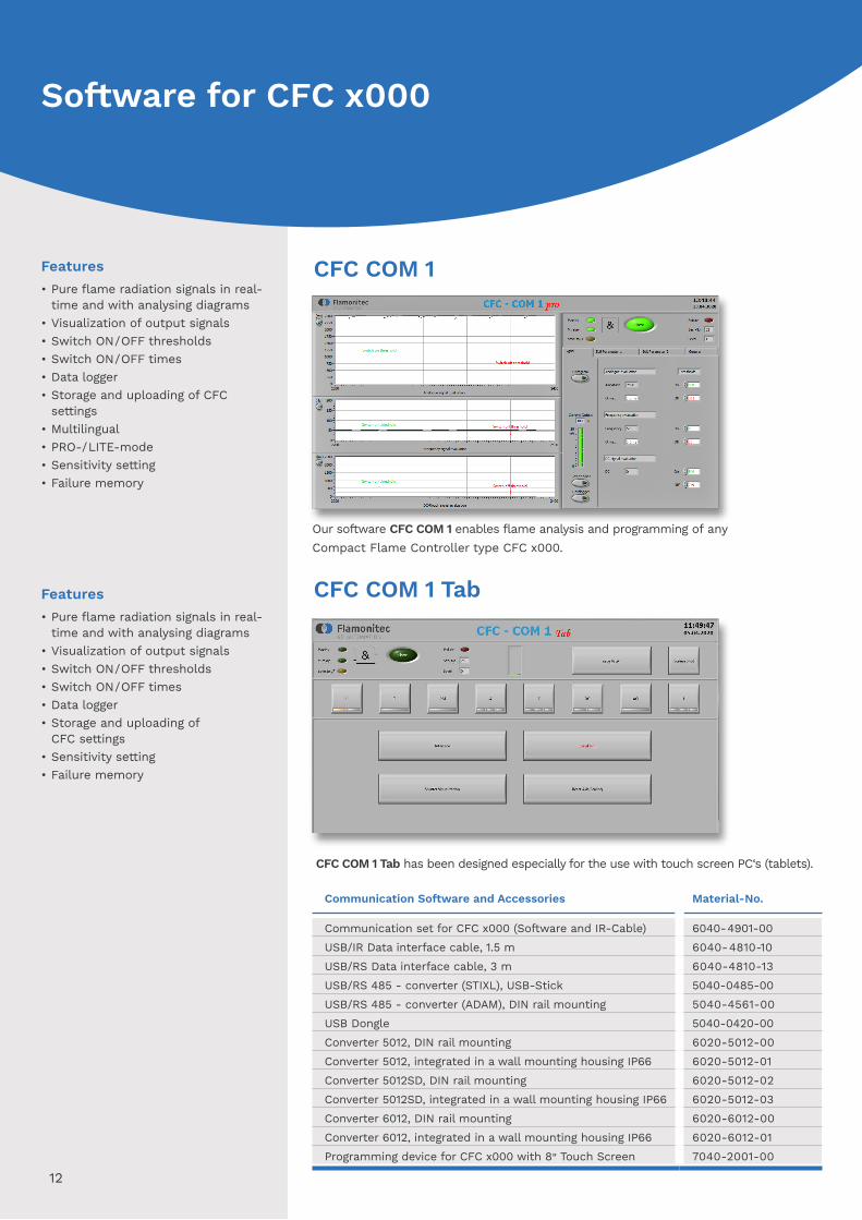
CFC COM 1 Tab
CFC COM 1
Our software CFC COM 1 enables flame analysis and programming of any Compact Flame Controller type CFC x000.
CFC COM 1 Tab has been designed especially for the use with touch screen PC‘s (tablets).
Communication Software and Accessories Material-No.
Communication set for CFC x000 (Software and IR-Cable) 6040-4901-00USB/IR Data interface cable, 1.5 m 6040-4810-10USB/RS Data interface cable, 3 m 6040-4810-13USB/RS 485 - converter (STIXL), USB-Stick 5040-0485-00USB/RS 485 - converter (ADAM), DIN rail mounting 5040-4561-00USB Dongle 5040-0420-00Converter 5012, DIN rail mounting 6020-5012-00Converter 5012, integrated in a wall mounting housing IP66 6020-5012-01Converter 5012SD, DIN rail mounting 6020-5012-02Converter 5012SD, integrated in a wall mounting housing IP66 6020-5012-03Converter 6012, DIN rail mounting 6020-6012-00Converter 6012, integrated in a wall mounting housing IP66 6020-6012-01Programming device for CFC x000 with 8" Touch Screen 7040-2001-00
12
Software for CFC x000
Features• Analyzing on diagrams in real-time• Switchover from boiler overview to
burner view• Visualization of output signals• Switch ON/OFF thresholds • Switch ON/OFF times• Sensitivity settings• SD-Card data logger with 5012SD or 6012• Multilingual• Configuration menu• Failure memory• Remote programming of CFC 4000
with converter 6012 from control room via USB Dongle
13
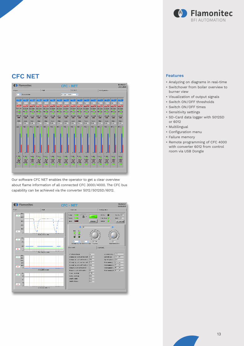
Our software CFC NET enables the operator to get a clear overview about flame information of all connected CFC 3000/4000. The CFC bus capability can be achieved via the converter 5012/5012SD/6012.
CFC NET
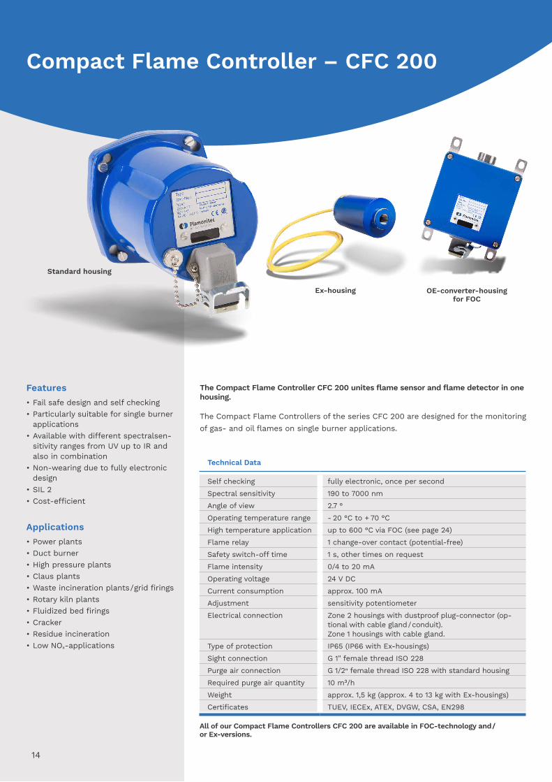
The Compact Flame Controller CFC 200 unites flame sensor and flame detector in one housing.
The Compact Flame Controllers of the series CFC 200 are designed for the monitoringof gas- and oil flames on single burner applications.
Technical Data
Self checking fully electronic, once per secondSpectral sensitivity 190 to 7000 nmAngle of view 2.7 °Operating temperature range - 20 °C to + 70 °CHigh temperature application up to 600 °C via FOC (see page 24)Flame relay 1 change-over contact (potential-free)Safety switch-off time 1 s, other times on requestFlame intensity 0/4 to 20 mAOperating voltage 24 V DCCurrent consumption approx. 100 mAAdjustment sensitivity potentiometerElectrical connection Zone 2 housings with dustproof plug-connector (op-
tional with cable gland / conduit).Zone 1 housings with cable gland.
Type of protection IP65 (IP66 with Ex-housings)Sight connection G 1" female thread ISO 228Purge air connection G 1/2" female thread ISO 228 with standard housingRequired purge air quantity 10 m³/hWeight approx. 1,5 kg (approx. 4 to 13 kg with Ex-housings)Certificates TUEV, IECEx, ATEX, DVGW, CSA, EN298
Features• Fail safe design and self checking• Particularly suitable for single burner
applications• Available with different spectralsen-
sitivity ranges from UV up to IR and also in combination
• Non-wearing due to fully electronic design
• SIL 2• Cost-efficient
Applications• Power plants• Duct burner• High pressure plants• Claus plants• Waste incineration plants/grid firings• Rotary kiln plants• Fluidized bed firings• Cracker• Residue incineration• Low NOx-applications
All of our Compact Flame Controllers CFC 200 are available in FOC-technology and/ or Ex-versions.
Ex-housing OE-converter-housing for FOC
14
Standard housing
Compact Flame Controller – CFC 200

Applications
CFC Type
Spectral Range
Spectral Sensitivity
Gas Oil
CFC 200 UV1 UV/VIS 190 to 550 nm CFC 200 UV UV 280 to 420 nm CFC 200 IR UV/IR 300 to 1050 nm -CFC 200 IR3 IR 1050 to 2700 nm
IP66, ATEX Zone 1, similar to NEMA4/Class 1 Div 1
IP65, ATEX Zone 2, similar to NEMA4/Class 1 Div 2
Dimensions
Type of combustions• Light- and heavy fuel oil• Natural-, furnance- and coke oven gas• Biomass• H2S-gas
Accessories• Swivel mount• Ball valve• Heating insulator• Pressure barrier• Signal generator• Special cable• Alignment tool• Heating• Tropicalization
15
267302
206
232
5570
∅ 1
20
G 1
22363
24 V DC
24 V DC
108
190
Purge air
24 V DC
235
G 1
G 1/2
106
122
152120
OE-converter-housing for FOC
Ex-OE-converter-housing for Ex-FOC
Ex-housing
Standard housing
Features• Fail safe design and self checking• Certified for continuous and inter-
mittent operation• Qualified for single and multi burner
applications• Dual channel flame monitoring
system• Intensity and relay status indication
via LED• 3 times increased lifetime of the
UV-tube• 20 times increased shutter lifetime
Applications• Power plants• Duct burner• Surface burner• Rotary kiln plants• Fluidized bed firings• Cracking• Mesh burner• Quartz burner• Waste incineration plants• Low NOx-applications
Type of combustions• Natural gas• Oil• Mix firing
Accessories• Hand programming device• Operating terminal• Power supply• Swivel mount• Ball valve• Heating insulator• Pressure barriere• Signal generator• Special cable• Alignment tool• Heating• Tropicalization
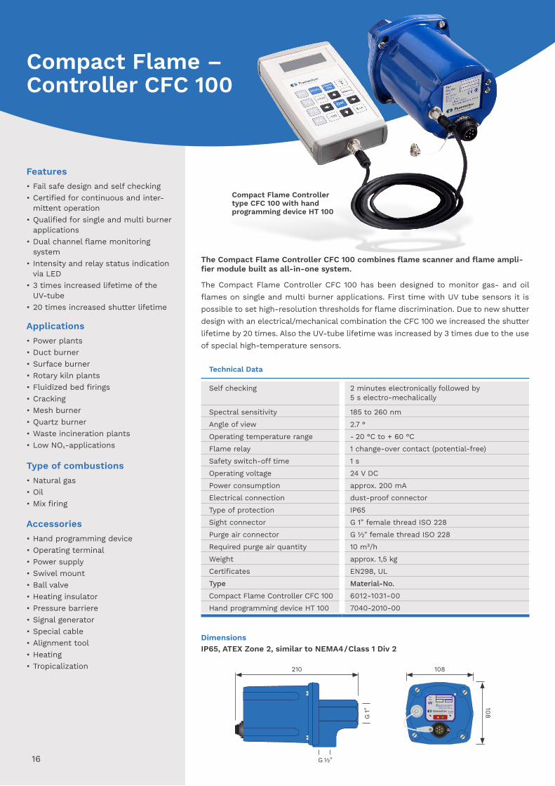
The Compact Flame Controller CFC 100 combines flame scanner and flame ampli-fier module built as all-in-one system.
The Compact Flame Controller CFC 100 has been designed to monitor gas- and oil flames on single and multi burner applications. First time with UV tube sensors it is possible to set high-resolution thresholds for flame discrimination. Due to new shutter design with an electrical/mechanical combination the CFC 100 we increased the shutter lifetime by 20 times. Also the UV-tube lifetime was increased by 3 times due to the use of special high-temperature sensors.
Technical Data
Self checking 2 minutes electronically followed by 5 s electro-mechalically
Spectral sensitivity 185 to 260 nmAngle of view 2.7 °Operating temperature range - 20 °C to + 60 °CFlame relay 1 change-over contact (potential-free)Safety switch-off time 1 sOperating voltage 24 V DCPower consumption approx. 200 mAElectrical connection dust-proof connectorType of protection IP65Sight connector G 1" female thread ISO 228Purge air connector G ½" female thread ISO 228Required purge air quantity 10 m³/hWeight approx. 1,5 kgCertificates EN298, ULType Material-No.Compact Flame Controller CFC 100 6012-1031-00Hand programming device HT 100 7040-2010-00
Compact Flame Controller type CFC 100 with hand programming device HT 100
IP65, ATEX Zone 2, similar to NEMA4/Class 1 Div 2Dimensions
16
CFC100Typ:S/N:
24VDC200mA
-20 - +70°C
Do not open while energized II3G Ex ec nC T4 GcII3D Ex tc IIIC T100°C Dc
G 1"
210 108
G 1/2"
108Compact Flame – Controller CFC 100
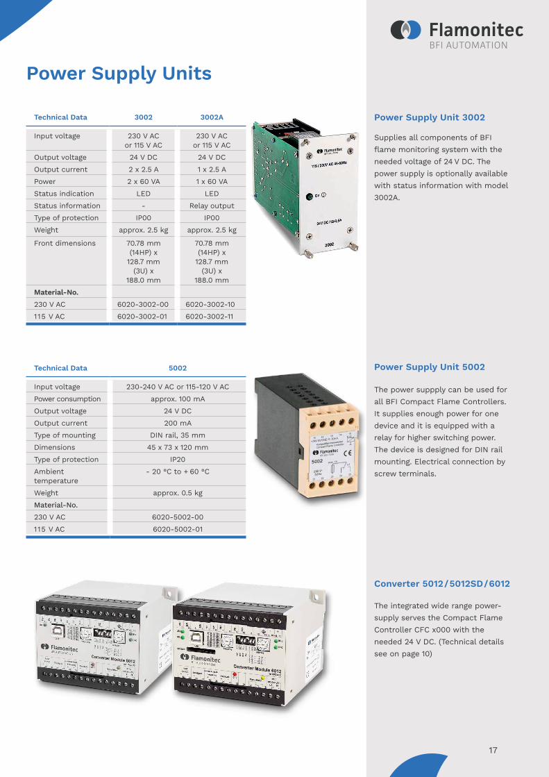
Power Supply Unit 3002
Supplies all components of BFI flame monitoring system with the needed voltage of 24 V DC. The power supply is optionally available with status information with model 3002A.
Power Supply Unit 5002
The power suppply can be used for all BFI Compact Flame Controllers. It supplies enough power for one device and it is equipped with a relay for higher switching power. The device is designed for DIN rail mounting. Electrical connection by screw terminals.
Converter 5012/5012SD/6012
The integrated wide range power-supply serves the Compact Flame Controller CFC x000 with the needed 24 V DC. (Technical details see on page 10)
Technical Data 3002 3002A
Input voltage 230 V ACor 115 V AC
230 V ACor 115 V AC
Output voltage 24 V DC 24 V DCOutput current 2 x 2.5 A 1 x 2.5 APower 2 x 60 VA 1 x 60 VAStatus indication LED LEDStatus information - Relay outputType of protection IP00 IP00Weight approx. 2.5 kg approx. 2.5 kg
Front dimensions 70.78 mm (14HP) x
128.7 mm (3U) x
188.0 mm
70.78 mm (14HP) x
128.7 mm (3U) x
188.0 mmMaterial-No.230 V AC 6020-3002-00 6020-3002-10115 V AC 6020-3002-01 6020-3002-11
Technical Data 5002
Input voltage 230-240 V AC or 115-120 V ACPower consumption approx. 100 mAOutput voltage 24 V DCOutput current 200 mAType of mounting DIN rail, 35 mmDimensions 45 x 73 x 120 mmType of protection IP20Ambient temperature
- 20 °C to + 60 °C
Weight approx. 0.5 kgMaterial-No.230 V AC 6020-5002-00115 V AC 6020-5002-01
17
Power Supply Units
Technical Data 3012
Power supply 24 V DCCurrent consumption
approx. 100mA
Decoupling 4 x 2,5 A; 24 V DCVoltage monitoringLow voltageHigh voltage
24 V DC- 20 %+ 20 %
Failure alarm output
switch over relay contact,one per channel
Failure alarmreset
local or remote
Status indication operation: LED greenalarm: LED red
Type of protection IP00
Weight approx. 0.4 kgDimensions 70.78 mm (14HP)
x 128.7 mm (3U)x 188.0 mm
Material-No. 6020-3012-00
Technical Data 3003
Power supply 24 V DCCurrent consumption
approx. 100mA
Intensity indicator LED-7-segment 3-digitStatus indication relais output (RD)
fault diagnostic (FD)
Threshold adjustable, 001 to 999Switch-ON delay adjustable, 1s to 9sSwitch-OFF delay adjustable, 1s to 9s
Type of protection IP00
Weight approx. 0,5 kgDimensions 70.78 mm (14HP)
x 128.7 mm (3U)x 188.0 mm
Material-No. 6020-3003-00
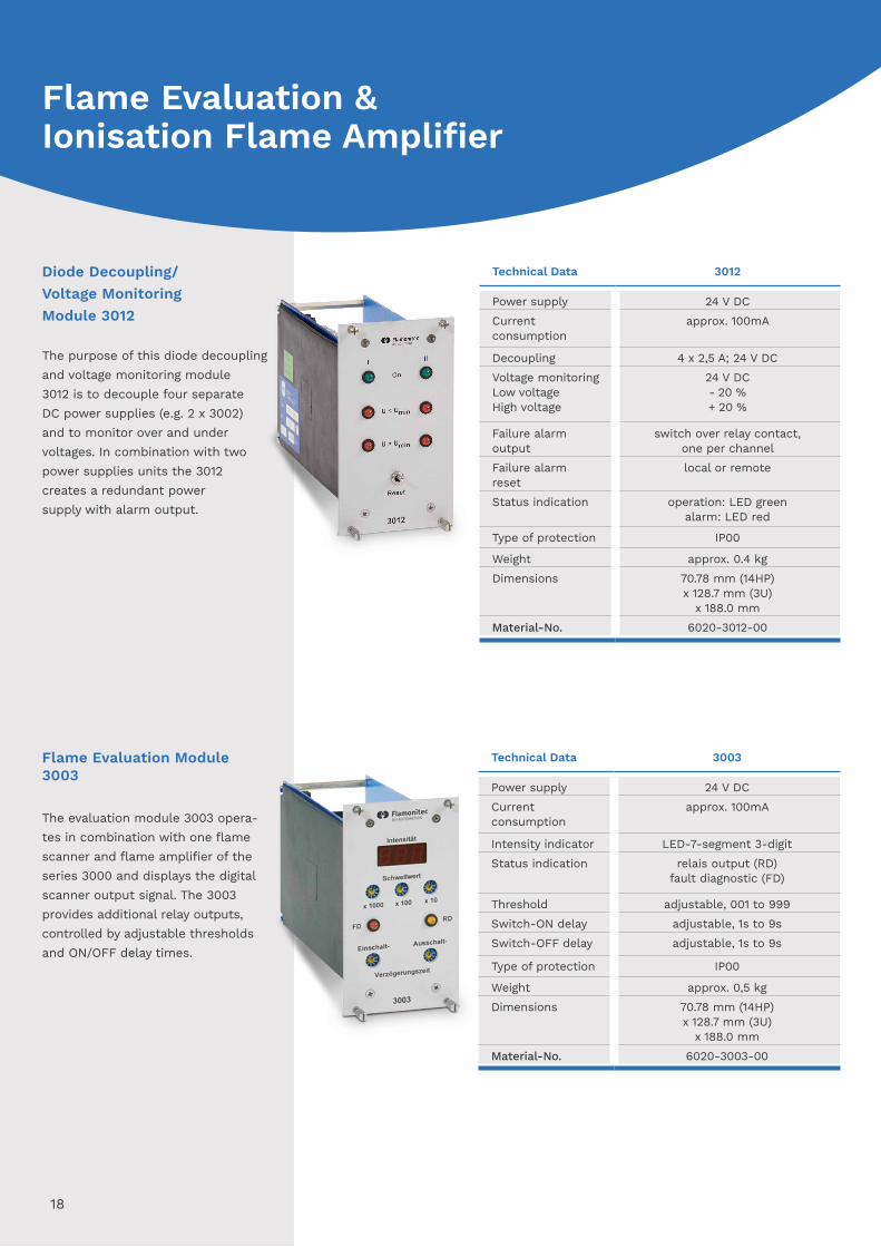
Diode Decoupling/Voltage Monitoring Module 3012
The purpose of this diode decouplingand voltage monitoring module3012 is to decouple four separateDC power supplies (e.g. 2 x 3002)and to monitor over and undervoltages. In combination with twopower supplies units the 3012 creates a redundant power supply with alarm output.
Flame Evaluation Module 3003
The evaluation module 3003 opera-tes in combination with one flame scanner and flame amplifier of the series 3000 and displays the digital scanner output signal. The 3003 provides additional relay outputs, controlled by adjustable thresholds and ON/OFF delay times.
18
Flame Evaluation & Ionisation Flame Amplifier
Technical Data 3210
Power supply 24 V DCCurrent consumption
approx. 100 mA
Signal output selected flame scanner signal, summarized flame signal,
failure alarm contact
Status indication two-color-LED per Signal,failure alarm-LED
Failure alarm relay 2 switch-over contacts,250 V/ 1A / 300 VA
Type of protection IP00
Weight approx. 0.3 kg
Dimensions 70.78 mm (14HP)x 128.7 mm (3U)
x 188.0 mmMaterial-No. 6020-3210-00
Technical Data 3007
Power supply 24 V DCCurrent consumption
approx. 340 mA
Channels 4Output per channel
0/4 to 20 mA,max. load 500 Ohms
Measurement ranges
5 selectable
Type of protection IP00Weight approx. 0.4 kgDimensions 70.78 mm (14HP)
x 128.7 mm (3U)x 188.0 mm
Material-No. 6020-3007-00
Technical Data 3011
Power supply 115/230 V ACCurrent consumption
approx. 50 mA
Relay output 2 switch-over contacts250 V, 1A
Mode of operation in combination with ignition-/ ionization electrodes
Status indication 3 LEDsType of protection IP00Weight approx. 0.4 kg
Dimensions 35.22 mm (7HP)x 128.7 mm (3U)
x 188.0 mmConnector DIN 41612 Form CModel type Material-No.3011 for continuousoperation
6020-3011-01
3011 for 72 h operation
6020-3011-02
19
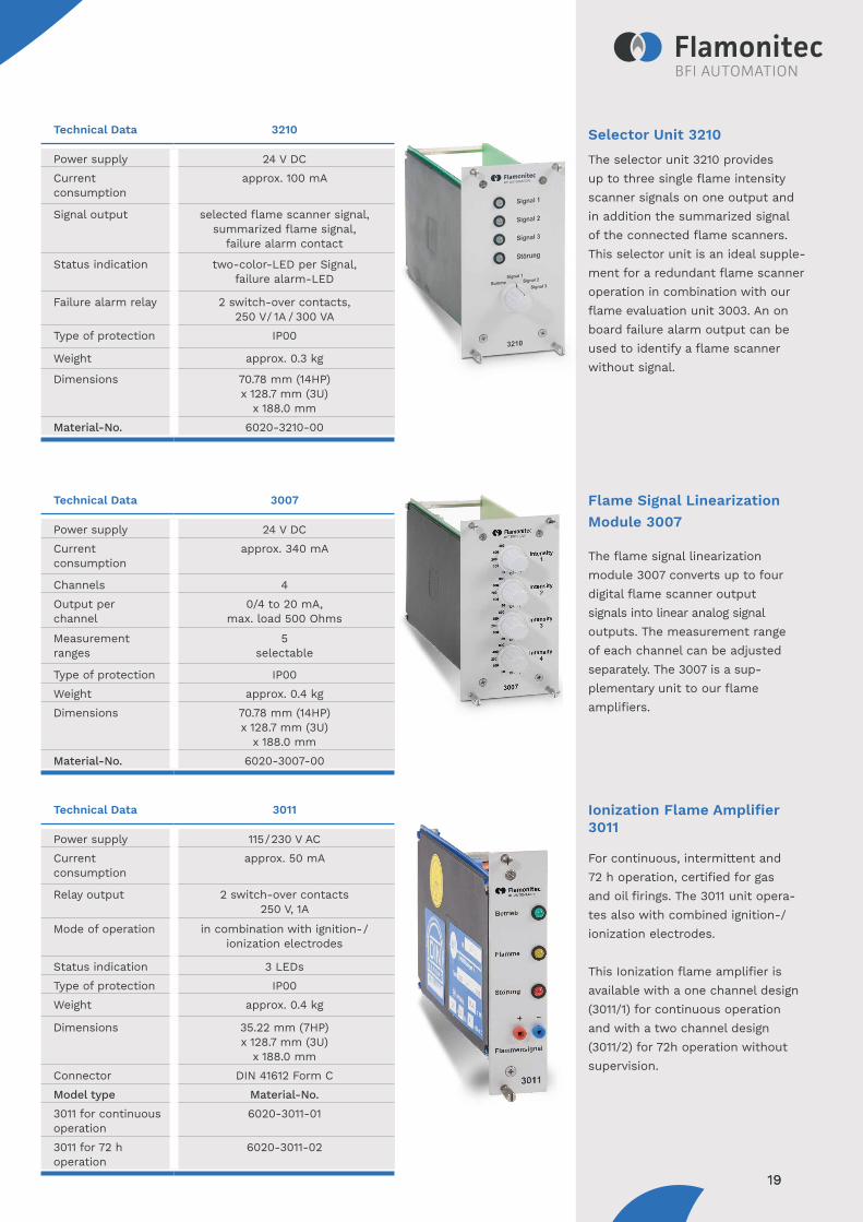
Selector Unit 3210
The selector unit 3210 providesup to three single flame intensityscanner signals on one output andin addition the summarized signalof the connected flame scanners.This selector unit is an ideal supple-ment for a redundant flame scanneroperation in combination with ourflame evaluation unit 3003. An onboard failure alarm output can beused to identify a flame scannerwithout signal.
Flame Signal LinearizationModule 3007
The flame signal linearization module 3007 converts up to four digital flame scanner output signals into linear analog signal outputs. The measurement range of each channel can be adjusted separately. The 3007 is a sup-plementary unit to our flame amplifiers.
Ionization Flame Amplifier 3011
For continuous, intermittent and72 h operation, certified for gas and oil firings. The 3011 unit opera-tes also with combined ignition-/ionization electrodes.
This Ionization flame amplifier isavailable with a one channel design(3011/1) for continuous operationand with a two channel design(3011/2) for 72h operation withoutsupervision.
19
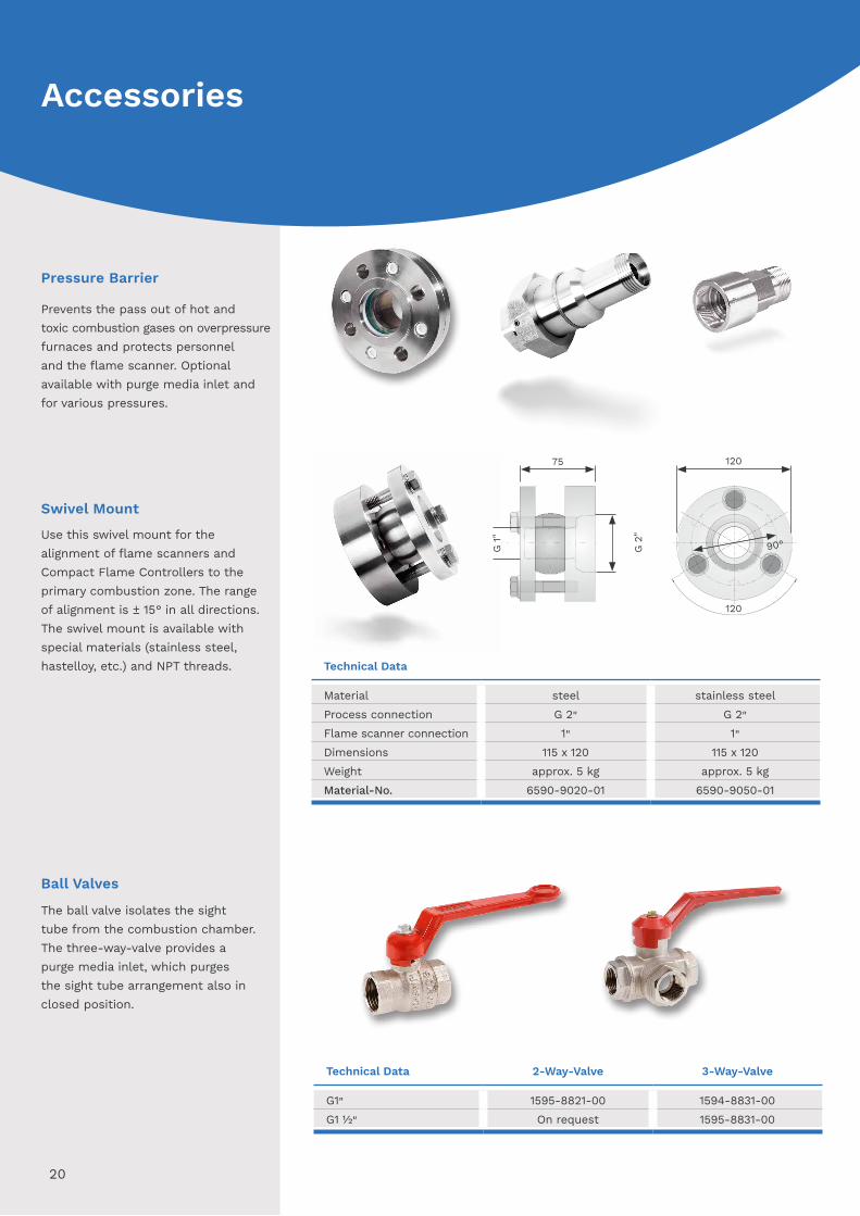
Pressure Barrier
Prevents the pass out of hot andtoxic combustion gases on overpressure furnaces and protects personneland the flame scanner. Optionalavailable with purge media inlet andfor various pressures.
Technical Data 2-Way-Valve 3-Way-Valve
G1" 1595-8821-00 1594-8831-00G1 ½" On request 1595-8831-00
Ball Valves
The ball valve isolates the sighttube from the combustion chamber.The three-way-valve provides apurge media inlet, which purgesthe sight tube arrangement also inclosed position.
Swivel Mount
Use this swivel mount for thealignment of flame scanners andCompact Flame Controllers to the primary combustion zone. The range of alignment is ± 15 ° in all directions. The swivel mount is available with special materials (stainless steel, hastelloy, etc.) and NPT threads. Technical Data
Material steel stainless steelProcess connection G 2" G 2"Flame scanner connection 1" 1"Dimensions 115 x 120 115 x 120Weight approx. 5 kg approx. 5 kgMaterial-No. 6590-9020-01 6590-9050-01
20
Accessories
75 120
90°
120
G2"
G1"
Type Material-No.
Special cable KW5 6060-0560-00Special cable KW5-UL 6060-0570-00Special cable KW6 6060-0680-00Special cable KW6-UL 6060-0670-00Mounting of connector 9080-1201-00 (including connector)Mounting of connector 9080-1202-00 (excluding connector)
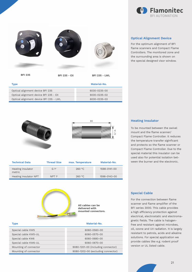
Optical Alignment Device
For the optimum alignment of BFIflame scanners and Compact FlameControllers. The monitored zone andthe surrounding area is shown onthe special designed visor window.
Heating Insulator
To be mounted between the swivelmount and the flame scanner/Compact Flame Controller. It reduces the temperature transfer siginficant and protects so the flame scanner or Compact Flame Controller. Due to the special material this insulator can be used also for potential isolation bet-ween the burner and the electronic.
Special Cable
For the connection between flamescanner and flame amplifier of theBFI series 3000. This cable providesa high efficiency protection againstelectrical, electrostatic and electroma-gnetic fields. The cable is halogen-free and resistant against microbes, oil, ozone and UV radiation. It is largely resistant to petrols, acids and alkaline solutions. For special application we provide cables like e.g. rodent proof version or UL listed cable.
All cables can be delivered withmounted connectors.
Type Material-No.
Optical alignment device BFI 235 6030-0235-00Optical alignment device BFI 235 - EX 6030-0235-02Optical alignment device BFI 235 - LWL 6030-0235-03
BFI 235 BFI 235 - EX BFI 235 - LWL
21
Technical Data Thread Size max. Temperature Material-No.
Heating insulator metric
G 1" 260 °C 1598-0141-00
Heating insulator NPT NPT 1" 260 °C 1598-0143-00
G1A
80
TypeMaterial-No. (standard)
Material-No. (with state indicator)
Measuring adapter BFI 234with Harting connector
Measuring adapter BFI 236 (OR operation)
Measuring adapter BFI 237 (AND operation)
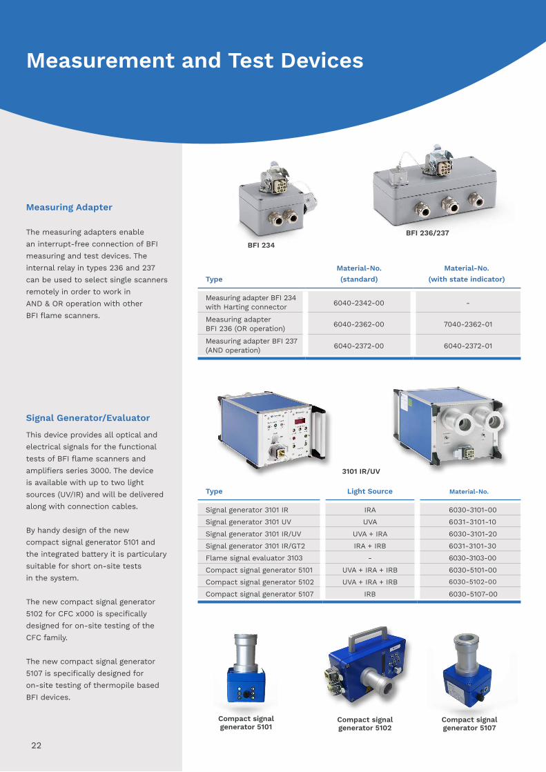
Measuring Adapter
The measuring adapters enablean interrupt-free connection of BFImeasuring and test devices. Theinternal relay in types 236 and 237can be used to select single scanners remotely in order to work inAND & OR operation with otherBFI flame scanners.
Signal Generator/Evaluator
This device provides all optical andelectrical signals for the functionaltests of BFI flame scanners andamplifiers series 3000. The deviceis available with up to two lightsources (UV/IR) and will be deliveredalong with connection cables.
By handy design of the newcompact signal generator 5101 andthe integrated battery it is particularysuitable for short on-site testsin the system.
The new compact signal generator5102 for CFC x000 is specificallydesigned for on-site testing of theCFC family.
The new compact signal generator5107 is specifically designed foron-site testing of thermopile basedBFI devices.
3101 IR/UV
Compact signal generator 5101
22
BFI 234
BFI 236/237
Type Light Source Material-No.
Signal generator 3101 IR IRA 6030-3101-00Signal generator 3101 UV UVA 6031-3101-10Signal generator 3101 IR/UV UVA + IRA 6030-3101-20Signal generator 3101 IR/GT2 IRA + IRB 6031-3101-30Flame signal evaluator 3103 - 6030-3103-00Compact signal generator 5101 UVA + IRA + IRB 6030-5101-00Compact signal generator 5102 UVA + IRA + IRB 6030-5102-00
Compact signal generator 5107 IRB 6030-5107-00
Compact signal generator 5107
Compact signal generator 5102
Measurement and Test Devices
6040-2342-00 -
6040-2362-00 7040-2362-01
6040-2372-00 6040-2372-01
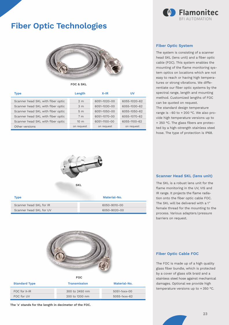
Standard Type Transmission Material-No.
FOC for X-IR 300 to 2450 nm 5051-1xxx-00FOC for UV 200 to 1200 nm 5055-1xxx-62
Fiber Optic System
The system is consisting of a scanner head SKL (lens unit) and a fiber optic cable (FOC). This system enables the mounting of the flame monitoring sys-tem optics on locations which are not easy to reach or having high tempera-tures or strong vibrations. We diffe-rentiate our fiber optic systems by the spectral range, length and mounting method. Customized lengths of FOC can be quoted on request. The standard design temperature range is - 60 to + 200 °C. We also pro-vide high temperature versions up to + 350 °C. The glass fibers are protec-ted by a high-strength stainless steel hose. The type of protection is IP68.
Scanner Head SKL (lens unit)
The SKL is a robust lens unit for the flame monitoring in the UV, VIS and IR range. It projects the flame radia-tion onto the fiber optic cable FOC. The SKL will be delivered with a 1" female thread for the mounting to the process. Various adapters/pressure barriers on request.
Fiber Optic Cable FOC
The FOC is made up of a high quality glass fiber bundle, which is protected by a cover of glass silk braid and a stainless steel hose against mechanical damages. Optional we provide high temperature versions up to + 350 °C.
Fiber Optic Technologies
Type Material-No.
Scanner head SKL for IR 6050-9010-00Scanner head SKL for UV 6050-9020-00
SKL
FOC
23
Type Length X-IR UV
Scanner head SKL with fiber optic 2 m 6051-1020-00 6055-1020-62Scanner head SKL with fiber optic 3 m 6051-1030-00 6055-1030-62Scanner head SKL with fiber optic 5 m 6051-1050-00 6055-1050-62Scanner head SKL with fiber optic 7 m 6051-1070-00 6055-1070-62Scanner head SKL with fiber optic 10 m 6051-1100-00 6055-1100-62Other versions on request on request on request
FOC & SKL
The 'x' stands for the length in decimeter of the FOC.
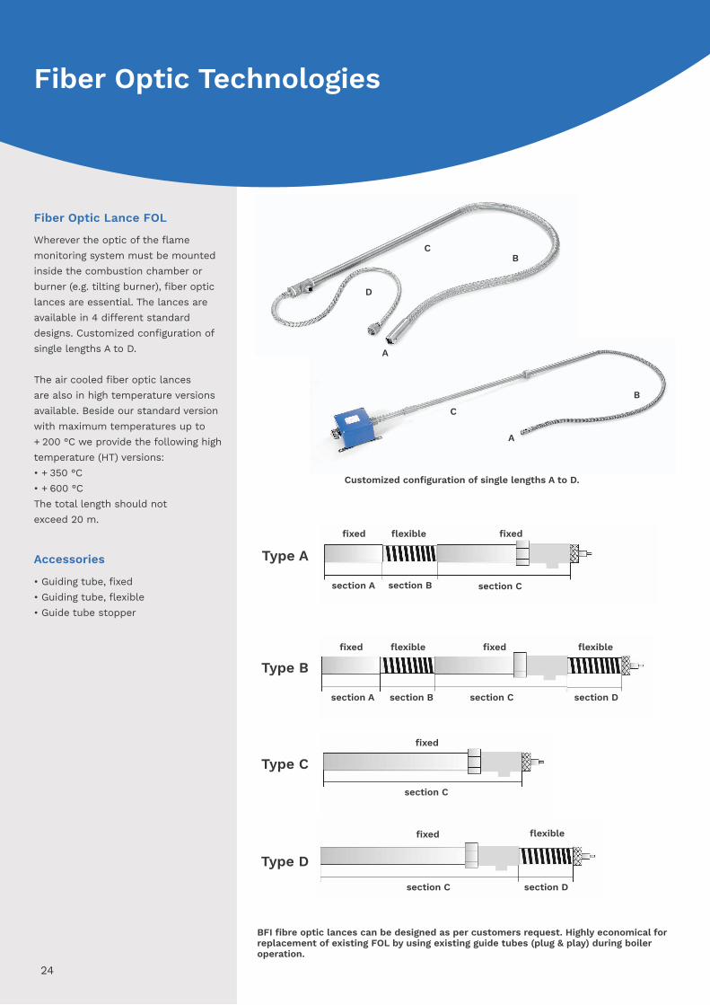
Fiber Optic Lance FOL
Wherever the optic of the flamemonitoring system must be mountedinside the combustion chamber orburner (e.g. tilting burner), fiber optic lances are essential. The lances are available in 4 different standarddesigns. Customized configuration of single lengths A to D.
The air cooled fiber optic lancesare also in high temperature versionsavailable. Beside our standard versionwith maximum temperatures up to + 200 °C we provide the following high temperature (HT) versions:• + 350 °C• + 600 °CThe total length should notexceed 20 m.
Accessories
• Guiding tube, fixed• Guiding tube, flexible• Guide tube stopper
BFI fibre optic lances can be designed as per customers request. Highly economical for replacement of existing FOL by using existing guide tubes (plug & play) during boiler operation.
24
Type Cfixed
section C
Type A
section A section B section C
fixedfixed flexible
Type Bfixed fixed
section A section B section C section D
flexible flexible
Type D
fixed
section C section D
flexible
Customized configuration of single lengths A to D.
Fiber Optic Technologies
D
C
A
B
C
A
B
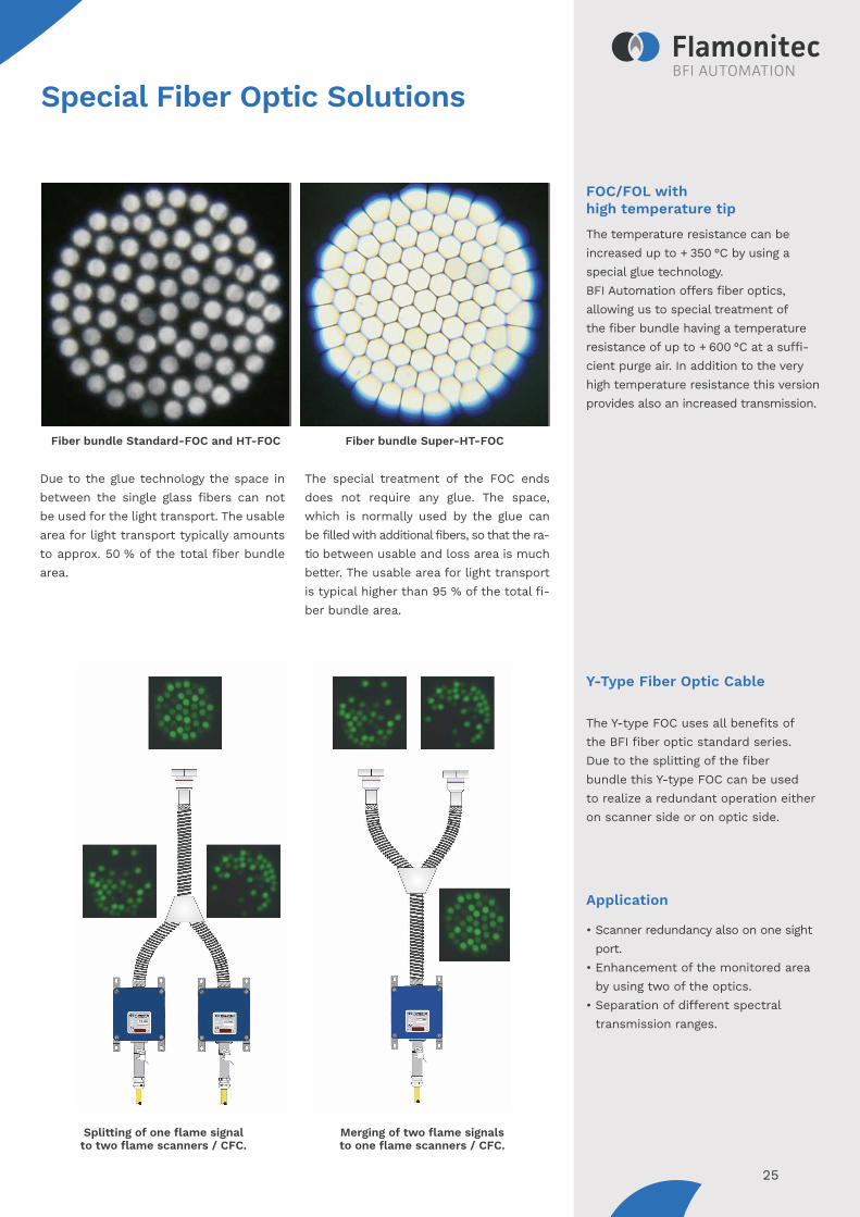
FOC/FOL with high temperature tip
The temperature resistance can beincreased up to + 350 °C by using a special glue technology. BFI Automation offers fiber optics, allowing us to special treatment of the fiber bundle having a temperature resistance of up to + 600 °C at a suffi-cient purge air. In addition to the very high temperature resistance this version provides also an increased transmission.
Y-Type Fiber Optic Cable
The Y-type FOC uses all benefits ofthe BFI fiber optic standard series.Due to the splitting of the fiberbundle this Y-type FOC can be usedto realize a redundant operation eitheron scanner side or on optic side.
Application
• Scanner redundancy also on one sight port.
• Enhancement of the monitored area by using two of the optics.
• Separation of different spectral transmission ranges.
Special Fiber Optic Solutions
Splitting of one flame signalto two flame scanners / CFC.
Merging of two flame signalsto one flame scanners / CFC.
25
Fiber bundle Standard-FOC and HT-FOC Fiber bundle Super-HT-FOC
Due to the glue technology the space in between the single glass fibers can not be used for the light transport. The usable area for light transport typically amounts to approx. 50 % of the total fiber bundle area.
The special treatment of the FOC ends does not require any glue. The space, which is normally used by the glue can be filled with additional fibers, so that the ra-tio between usable and loss area is much better. The usable area for light transport is typical higher than 95 % of the total fi-ber bundle area.

19"- built-in rack
For the series 3000 we provide19"-built-in-racks from one to sixplug-in units (14HP). The connectioncan be easily done via screw terminalsfrom the rearside. Alternative we provide standard connectors in accor-dance with international standards. Type of protection is IP20.
19"- built-on rack
For cabinet or wall mounting we provide 19"-built-on racks. The electricalconnection can be can be done via frontside screw terminals. Type ofprotection is IP20.
26
14HP 28HP 42HP 56HP 84HP
All dimensions± 0.4 mm
for 1 plug-in
unit series3000
for 2 plug-in
unit series3000
for 3 plug-in
unit series3000
for 4 plug-in
unit series3000
for 6 plug-in
unit series3000
Material-No. 6830-0701-01 6830-0702-01 6830-0703-01 6830-0704-01 6830-0706-01
14HP 28HP 42HP 56HP 84HP
All dimensions± 0.4 mm
for 1 plug-in
unit series3000
for 2 plug-in
unit series3000
for 3 plug-in
unit series3000
for 4 plug-in
unit series3000
for 6 plug-in
unit series3000
Material-No. 6830-0701-00 6830-0702-00 6830-0703-00 6830-0704-00 6830-0706-00
Housings and Racks
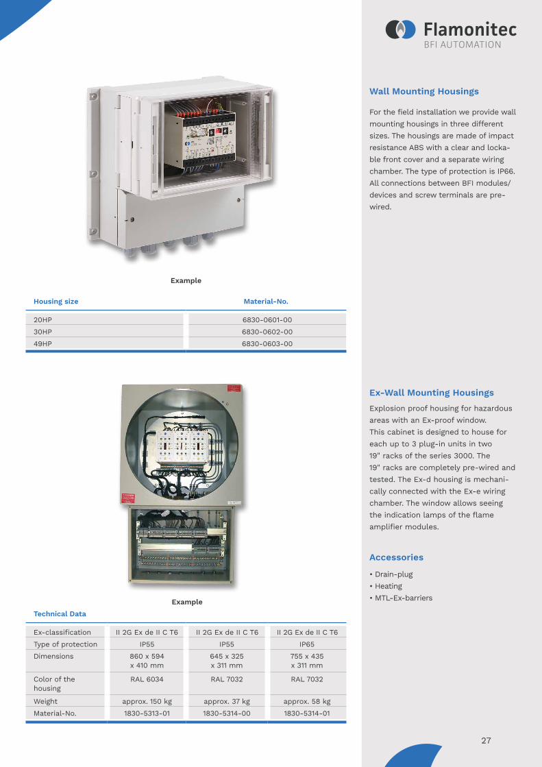
Wall Mounting Housings
For the field installation we provide wall mounting housings in three different sizes. The housings are made of impact resistance ABS with a clear and locka-ble front cover and a separate wiring chamber. The type of protection is IP66. All connections between BFI modules/devices and screw terminals are pre-wired.
Ex-Wall Mounting Housings
Explosion proof housing for hazardousareas with an Ex-proof window.This cabinet is designed to house foreach up to 3 plug-in units in two19" racks of the series 3000. The 19" racks are completely pre-wired andtested. The Ex-d housing is mechani-cally connected with the Ex-e wiringchamber. The window allows seeingthe indication lamps of the flameamplifier modules.
Accessories
• Drain-plug• Heating• MTL-Ex-barriers
27
Housing size Material-No.
20HP 6830-0601-0030HP 6830-0602-0049HP 6830-0603-00
Technical Data
Ex-classification II 2G Ex de II C T6 II 2G Ex de II C T6 II 2G Ex de II C T6Type of protection IP55 IP55 IP65Dimensions 860 x 594
x 410 mm645 x 325 x 311 mm
755 x 435 x 311 mm
Color of the housing
RAL 6034 RAL 7032 RAL 7032
Weight approx. 150 kg approx. 37 kg approx. 58 kgMaterial-No. 1830-5313-01 1830-5314-00 1830-5314-01
Example
Example
BFI Automation Mindermann GmbHRuegenstr. 7 42579 Heiligenhaus . GermanyT +49 2056 [email protected]
Subj
ect
to t
echn
ical
cha
nges
| ©
BFI
Aut
omat
ion
Min
derm
ann
Gm
bH 2
021-
11
Your sales partner
MEMBER OF MINDERMANN GROUP