Embed Size (px)
Citation preview
Visual PLC Productivity tools
Programmer’s
Guide
Editor Language Instruction Set
Ver 7.xx ARSoft international - Copyright © 1999

Page 2
Page 3
Structure of programs and datas..........................................................................................5
VPU Files (Visual Pascal Unit) .............................................................................. 5 MVARGLOB.VPU ................................................................................................ 5
Presentation of the editor......................................................................................................6 First Step.................................................................................................................................7
Project definition ............................................................................................... 7 Second Step............................................................................................................................8
Declare the process variables (Globals variables). .................................................. 8 The Types of Variables available in Visual PLC........................................................ 9
Third Step..............................................................................................................................10 Writing a Program in Ladder.............................................................................. 10 Loading the real time engine. ............................................................................ 11 Loading the real time engine. ............................................................................ 12 Mnemonics ..................................................................................................... 13 Invert Input or output parameter of a functional module ....................................... 13 Blocks of Programs (in line) .............................................................................. 14 Possibility of testing if the input is true in the program block.................................. 14 Writing a program in Grafcet............................................................................. 15 Create a GRAFCET ........................................................................................... 15 Renum steps................................................................................................... 16 Instructions and variables concerning a Grafcet ................................................... 16 Grafcet variables can be used by other programs ................................................. 17 Use of external functions in Grafcet.................................................................... 18
Introduction to the Pascal Language .................................................................................19 Textual commentaries ...................................................................................... 19 Identifiers ...................................................................................................... 20 Declarations ................................................................................................... 20 Boolean types :............................................................................................... 21 Arrays............................................................................................................ 21 Character strings............................................................................................. 21 The operators ................................................................................................. 22 The arithmetical operators ................................................................................ 22 Character string operator.................................................................................. 22 Logic operators ............................................................................................... 23 The boolean operators...................................................................................... 23 Tips & tricks ................................................................................................... 23 The Relational Operators .................................................................................. 24 Instructions .................................................................................................... 24 Simple Instructions.......................................................................................... 24 Affectations .................................................................................................... 24 Call of a procedure .......................................................................................... 24 Compound statements ..................................................................................... 25 IF THEN ELSE Statement .................................................................................. 25 REPEAT UNTIL Statement ................................................................................. 26 WHILE DO Statement....................................................................................... 26 CASE OF Statement ......................................................................................... 26 FOR TO /DOWNTO Statement............................................................................ 27 Procedures and functions.................................................................................. 28
Writing functional modules .................................................................................................29 Philosophy of a functional module ...................................................................... 29 Programming in a functional module .................................................................. 30 Test equation in Ladder validating the functional module....................................... 31 System Variables............................................................................................. 31 To quit the functional module ............................................................................ 31 Examples of functional modules......................................................................... 32 Tables transfer and typecast ............................................................................. 33
Page 4
Transfer a table in another table........................................................................ 34 Transfer of variables ........................................................................................ 35 Shift bits to left in consecutives words. ............................................................... 36 Call functions and procedure in a library VPU....................................................... 37 Compiling a functional module........................................................................... 37 Cross references ............................................................................................. 40
Statuts of the real time engine ............................................................................................41 Adding a program to the real time engine ........................................................... 42 Programs execution order of in the real time engine ............................................. 43 Saving the configuration of the real time engine .................................................. 43 Loading the configuration in the real time engine ................................................. 43
Writing cyclical programs in Pascal language ..................................................................44 The USES clause ............................................................................................. 44
Cyclical programs with interface ........................................................................................45 Writing VPU libraries............................................................................................................47
Initialization in a library.................................................................................... 48 Passing parameters by values and address.......................................................... 48
Calling procedures and functions in a DLL .......................................................................50 To redefine the name of the function contained in a DLL ....................................... 50 Localization of a DLL ........................................................................................ 50
Example of Visual PLC variable allocated in an external DLL .........................................51 Launching the real time engine automatically ..................................................................52 Visualization of programs loaded.......................................................................................53 Profibus Configuration tool for DPC102 Profibus card ....................................................54
Setting the equipment parameters ..................................................................... 55 Test of the Profibus card and ScanDP. ................................................................ 55 Testing the communication with connected Profibus equipment .............................. 56 Dangerous Interactions with Visual PLC .............................................................. 56
Maintenance of data.............................................................................................................57 To add a password protecting the editor...........................................................................59
Page 5
Structure of programs and datas With Arsoft’s compiler included, Visual PLC works differently to most traditional programs. All programs you write will be compiled at maximum speed, which means they are without external and additionnal programs. Each program (Ladder, Grafcet, Language etc….) will be checked for syntax errors, and then will be compiled in a file extension (.VPU). VPU Files (Visual Pascal Unit) These files are the result of program compilations. Once compiled, they contain all the variables and procedures declarations to be operated by the real time kernel or with other VPUs. A VPU could be the declaration of the application’s global variables in its simplest form. It could also be procedures or functions that you created for use in other programs. With the VPUs ‘pre-compiled’, programs using them do not need to have their source codes for running. It is impossible to know in what language a VPU has been written. We will see later on that VPUs have an Interface part and an Implementation part. Interfacing is the declaration of the variables or procedures that can be accessed by other VPUs. The implementation is the real part of the code. The ‘Driver’ programs communicating with the embedded cards in your PC are also VPUs allowing you to interface with physical elements (I/O) and the Input/Output image table that uses the program. MVARGLOB.VPU Within the Visual PLC package, Mvarglob.VPU is the basic file containing all the process variables, such as the input/output image table, internal variables, bits of the active steps and their activation time. Before starting to develop a program in Ladder, Grafcet or indeed any other packages, you need to declare the variables with the help of the Global Variable editor. Models of variables (pre-definitions) are implemented. With starting a new project, you can choose a model of variables (Schneider, Siemens, Allen Bradley Etc..). You can also add your own variables to this model.
Page 6
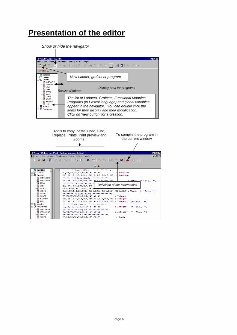
Presentation of the editor
The list of Ladders, Grafcets, Functional Modules, Programs (in Pascal language) and global variables appear in the navigator. You can double click the items for their display and their modification. Click on ‘new button’ for a creation.
New Ladder, grafcet or program.
Show or hide the navigator
Display area for programs Resize Windows
To compile the program in the current window
Tools to copy, paste, undo, Find, Replace, Prints, Print preview and
Zooms.
Definition of the Mnemonics
Page 7
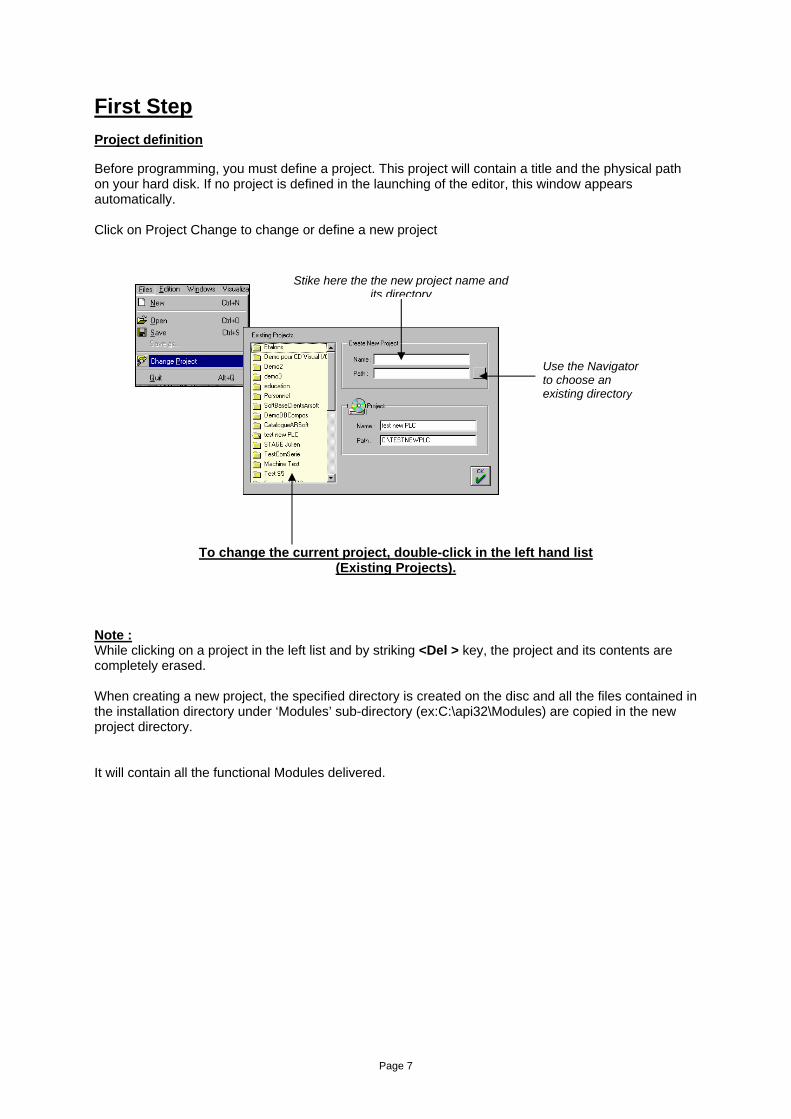
First Step Project definition Before programming, you must define a project. This project will contain a title and the physical path on your hard disk. If no project is defined in the launching of the editor, this window appears automatically. Click on Project Change to change or define a new project
To change the current project, double-click in the left hand list (Existing Projects).
Note : While clicking on a project in the left list and by striking <Del > key, the project and its contents are completely erased. When creating a new project, the specified directory is created on the disc and all the files contained in the installation directory under ‘Modules’ sub-directory (ex:C:\api32\Modules) are copied in the new project directory. It will contain all the functional Modules delivered.
Stike here the the new project name and its directory
Use the Navigator to choose an existing directory
Page 8
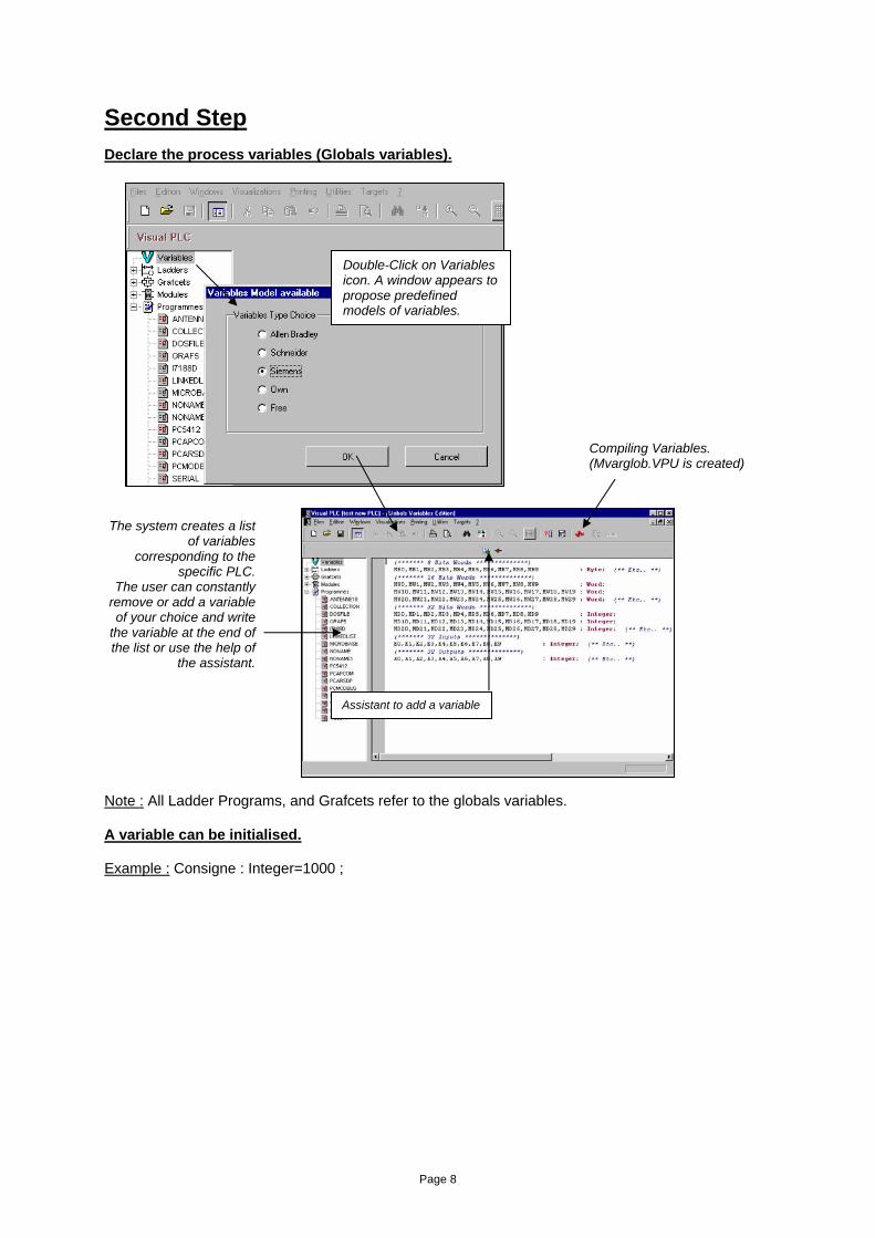
Second Step Declare the process variables (Globals variables). Note : All Ladder Programs, and Grafcets refer to the globals variables. A variable can be initialised. Example : Consigne : Integer=1000 ;
Double-Click on Variables icon. A window appears to propose predefined models of variables.
The system creates a list of variables
corresponding to the specific PLC.
The user can constantly remove or add a variable of your choice and write
the variable at the end of the list or use the help of
the assistant.
Assistant to add a variable
Compiling Variables. (Mvarglob.VPU is created)
Page 9
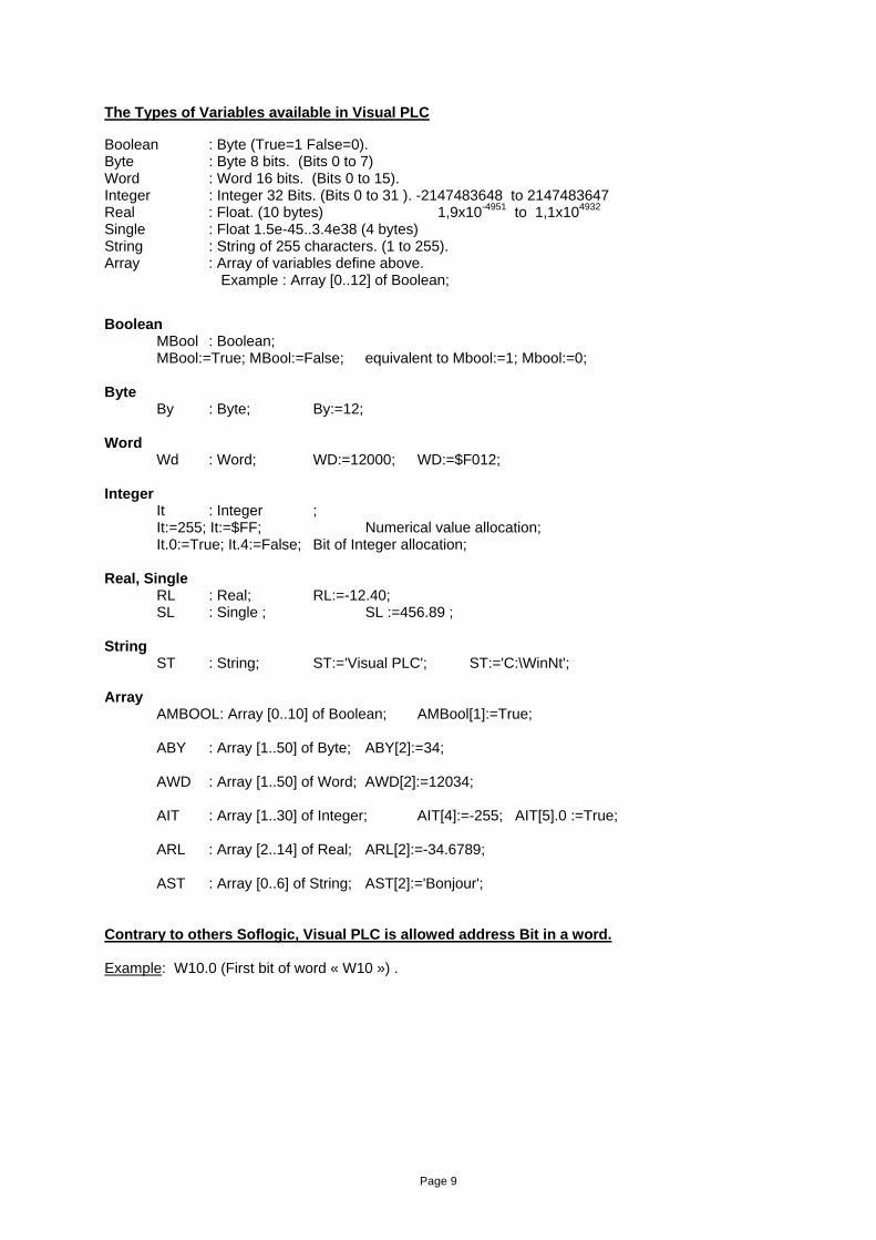
The Types of Variables available in Visual PLC Boolean : Byte (True=1 False=0). Byte : Byte 8 bits. (Bits 0 to 7) Word : Word 16 bits. (Bits 0 to 15). Integer : Integer 32 Bits. (Bits 0 to 31 ). -2147483648 to 2147483647 Real : Float. (10 bytes) 1,9x10-4951 to 1,1x104932 Single : Float 1.5e-45..3.4e38 (4 bytes)
String : String of 255 characters. (1 to 255). Array : Array of variables define above. Example : Array [0..12] of Boolean; Boolean
MBool : Boolean; MBool:=True; MBool:=False; equivalent to Mbool:=1; Mbool:=0;
Byte By : Byte; By:=12;
Word Wd : Word; WD:=12000; WD:=$F012;
Integer It : Integer ; It:=255; It:=$FF; Numerical value allocation;
It.0:=True; It.4:=False; Bit of Integer allocation; Real, Single RL : Real; RL:=-12.40; SL : Single ; SL :=456.89 ; String ST : String; ST:='Visual PLC'; ST:='C:\WinNt'; Array AMBOOL: Array [0..10] of Boolean; AMBool[1]:=True; ABY : Array [1..50] of Byte; ABY[2]:=34;
AWD : Array [1..50] of Word; AWD[2]:=12034;
AIT : Array [1..30] of Integer; AIT[4]:=-255; AIT[5].0 :=True; ARL : Array [2..14] of Real; ARL[2]:=-34.6789;
AST : Array [0..6] of String; AST[2]:='Bonjour'; Contrary to others Soflogic, Visual PLC is allowed address Bit in a word. Example: W10.0 (First bit of word « W10 ») .
Page 10
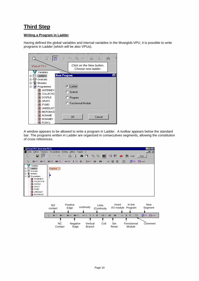
Third Step Writing a Program in Ladder Having defined the global variables and internal variables in the Mvarglob.VPU, it is possible to write programs in Ladder (which will be also VPUs). A window appears to be allowed to write a program in Ladder. A toolbar appears below the standard bar. The programs written in Ladder are organized in consecutives segments, allowing the constitution of cross references.
Click on the New button. Choose new ladder.
NO contact
NC Contact
Positive Edge
Negative Edge
continuity
Vertical Branch
Links (Continuity
Coil Set Reset
Invert I/O module
Fonctionnal Module
Comment
In line Program
New Segment
Page 11
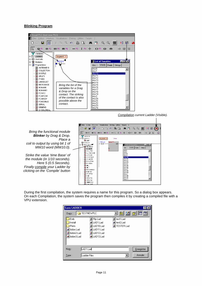
Blinking Program
During the first compilation, the system requires a name for this program. So a dialog box appears. On each Compilation, the system saves the program then compiles it by creating a compiled file with a VPU extension.
Bring the list of the variables for a Drag & Drop on the contact. The striking of the contact is also possible above the contact.
Bring the functional module Blinker by Drag & Drop.
Place a coil to output by using bit 1 of
MW10 word (MW10.0).
Strike the value ‘time Base’ of the module (in 1/10 seconds).
Here 5 (0.5 Seconds). Finally compile your Ladder by clicking on the ‘Compile’ button
Compilation current Ladder (Visible).
Page 12
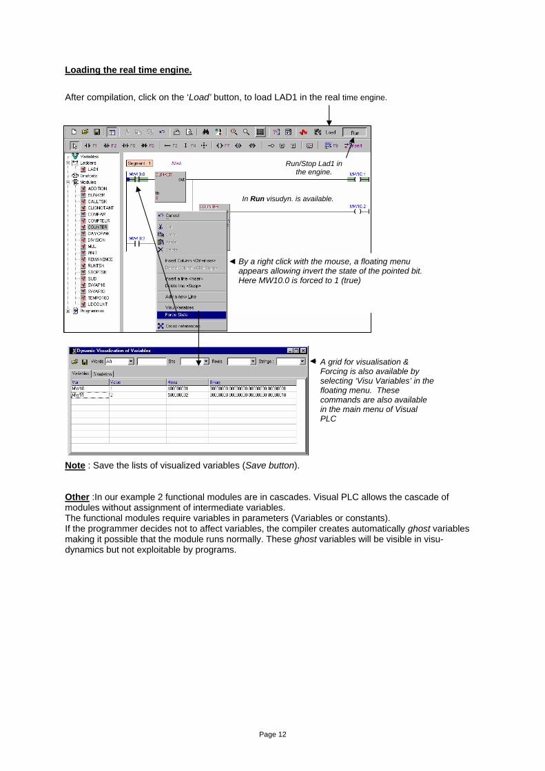
Loading the real time engine. After compilation, click on the ‘Load’ button, to load LAD1 in the real time engine. Note : Save the lists of visualized variables (Save button). Other :In our example 2 functional modules are in cascades. Visual PLC allows the cascade of modules without assignment of intermediate variables. The functional modules require variables in parameters (Variables or constants). If the programmer decides not to affect variables, the compiler creates automatically ghost variables making it possible that the module runs normally. These ghost variables will be visible in visu-dynamics but not exploitable by programs.
Run/Stop Lad1 in the engine.
In Run visudyn. is available.
By a right click with the mouse, a floating menu appears allowing invert the state of the pointed bit. Here MW10.0 is forced to 1 (true)
A grid for visualisation & Forcing is also available by selecting ‘Visu Variables’ in the floating menu. These commands are also available in the main menu of Visual PLC
Page 13
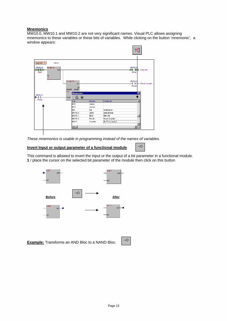
Mnemonics MW10.0, MW10.1 and MW10.2 are not very significant names. Visual PLC allows assigning mnemonics to these variables or these bits of variables. While clicking on the button ‘mnemonic’, a window appears: These mnemonics is usable in programming instead of the names of variables. Invert Input or output parameter of a functional module This command is allowed to invert the input or the output of a bit parameter in a functional module. 1 / place the cursor on the selected bit parameter of the module then click on this button
Before After
Example: Transforms an AND Bloc to a NAND Bloc.
Page 14
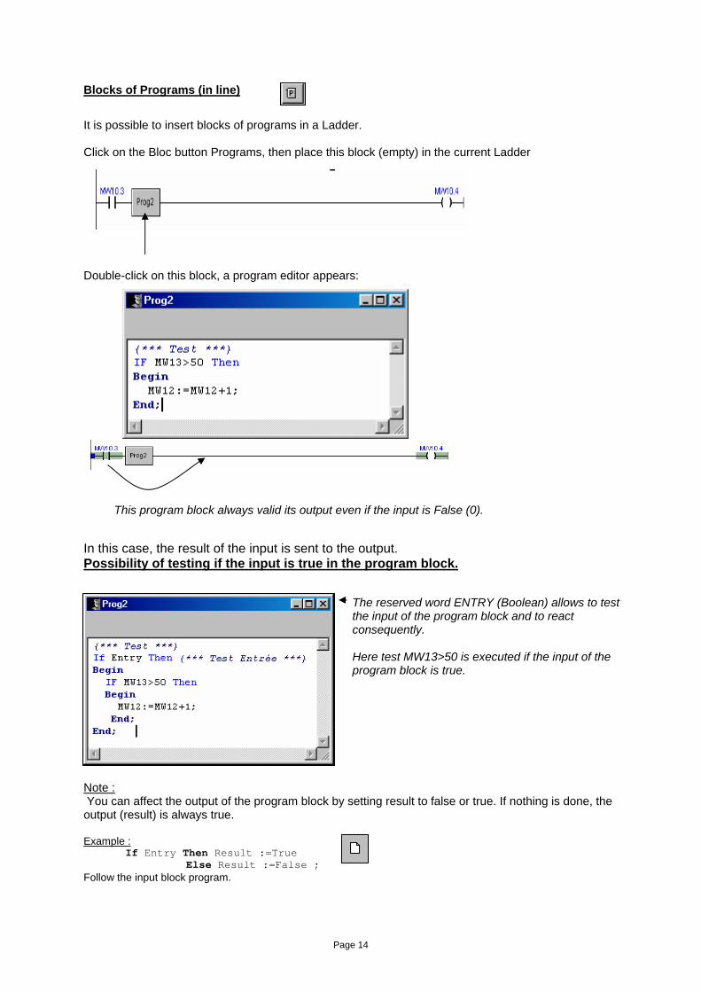
Blocks of Programs (in line) It is possible to insert blocks of programs in a Ladder. Click on the Bloc button Programs, then place this block (empty) in the current Ladder Double-click on this block, a program editor appears:
In this case, the result of the input is sent to the output. Possibility of testing if the input is true in the program block. Note : You can affect the output of the program block by setting result to false or true. If nothing is done, the output (result) is always true. Example : If Entry Then Result :=True Else Result :=False ; Follow the input block program.
This program block always valid its output even if the input is False (0).
The reserved word ENTRY (Boolean) allows to test the input of the program block and to react consequently. Here test MW13>50 is executed if the input of the program block is true.
Page 15
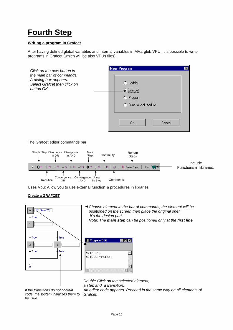
Fourth Step Writing a program in Grafcet After having defined global variables and internal variables in MVarglob.VPU, it is possible to write programs in Grafcet (which will be also VPUs files).
The Grafcet editor commands bar Uses Vpu: Allow you to use external function & procedures in libraries Create a GRAFCET
Click on the new button in the main bar of commands. A dialog box appears. Select Grafcet then click on button OK
Include Functions in libraries.
Choose element in the bar of commands, the element will be positioned on the screen then place the original onet. It’s the design part. Note: The main step can be positioned only at the first line.
Double-Click on the selected element, a step and a transition. An editor code appears. Proceed in the same way on all elements of Grafcet.
If the transitions do not contain code, the system initializes them to be True.
Simple Step
Transition
Divergence In OR
Convergence OR
Divergence In AND
Convergence AND
Main Step
Jump To Step
Continuity
Comments
Renum Steps
Page 16
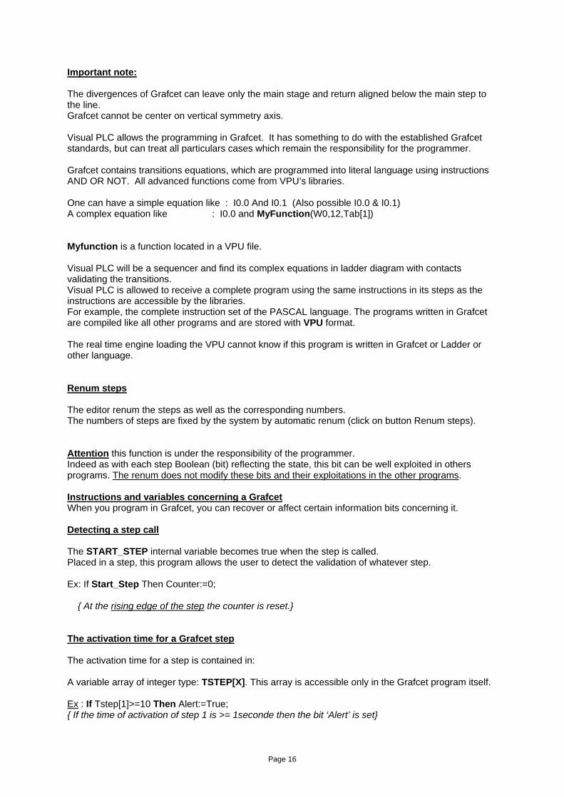
Important note: The divergences of Grafcet can leave only the main stage and return aligned below the main step to the line. Grafcet cannot be center on vertical symmetry axis. Visual PLC allows the programming in Grafcet. It has something to do with the established Grafcet standards, but can treat all particulars cases which remain the responsibility for the programmer. Grafcet contains transitions equations, which are programmed into literal language using instructions AND OR NOT. All advanced functions come from VPU’s libraries. One can have a simple equation like : I0.0 And I0.1 (Also possible I0.0 & I0.1) A complex equation like : I0.0 and MyFunction(W0,12,Tab[1]) Myfunction is a function located in a VPU file. Visual PLC will be a sequencer and find its complex equations in ladder diagram with contacts validating the transitions. Visual PLC is allowed to receive a complete program using the same instructions in its steps as the instructions are accessible by the libraries. For example, the complete instruction set of the PASCAL language. The programs written in Grafcet are compiled like all other programs and are stored with VPU format. The real time engine loading the VPU cannot know if this program is written in Grafcet or Ladder or other language. Renum steps The editor renum the steps as well as the corresponding numbers. The numbers of steps are fixed by the system by automatic renum (click on button Renum steps). Attention this function is under the responsibility of the programmer. Indeed as with each step Boolean (bit) reflecting the state, this bit can be well exploited in others programs. The renum does not modify these bits and their exploitations in the other programs. Instructions and variables concerning a Grafcet When you program in Grafcet, you can recover or affect certain information bits concerning it. Detecting a step call The START_STEP internal variable becomes true when the step is called. Placed in a step, this program allows the user to detect the validation of whatever step. Ex: If Start_Step Then Counter:=0; { At the rising edge of the step the counter is reset.} The activation time for a Grafcet step The activation time for a step is contained in: A variable array of integer type: TSTEP[X]. This array is accessible only in the Grafcet program itself. Ex : If Tstep[1]>=10 Then Alert:=True; { If the time of activation of step 1 is >= 1seconde then the bit ‘Alert’ is set}
Page 17
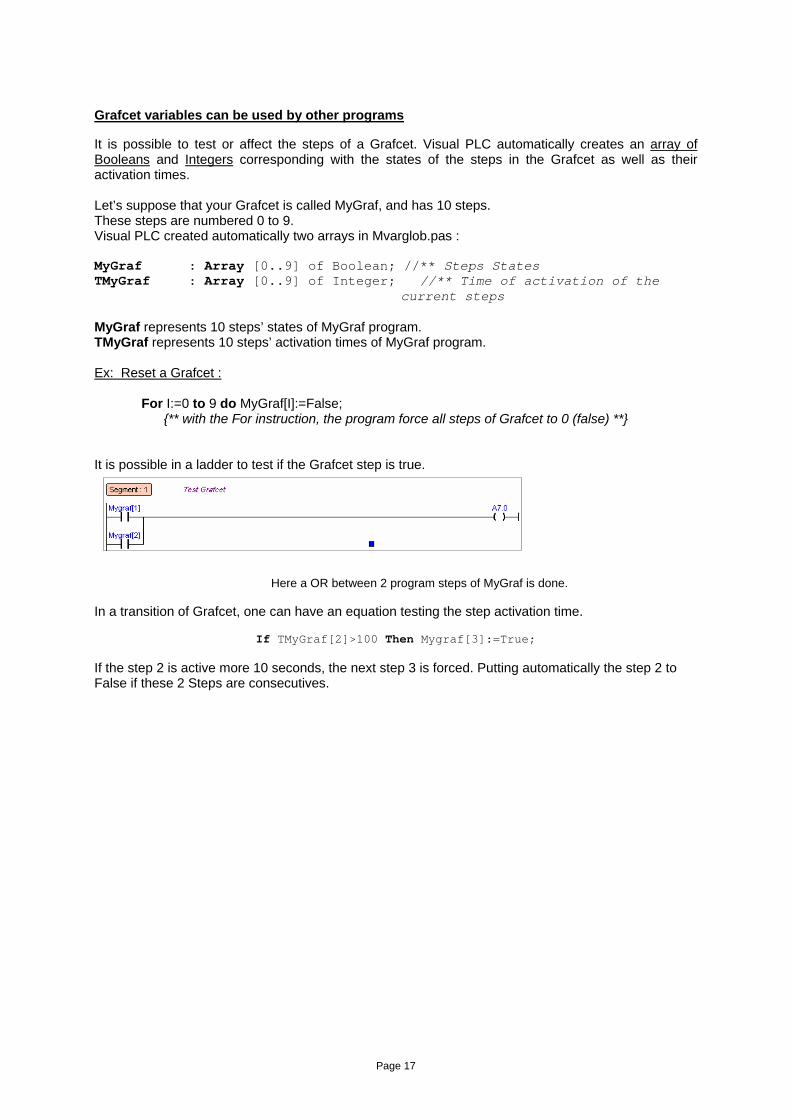
Grafcet variables can be used by other programs It is possible to test or affect the steps of a Grafcet. Visual PLC automatically creates an array of Booleans and Integers corresponding with the states of the steps in the Grafcet as well as their activation times. Let’s suppose that your Grafcet is called MyGraf, and has 10 steps. These steps are numbered 0 to 9. Visual PLC created automatically two arrays in Mvarglob.pas : MyGraf : Array [0..9] of Boolean; //** Steps States TMyGraf : Array [0..9] of Integer; //** Time of activation of the
current steps MyGraf represents 10 steps’ states of MyGraf program. TMyGraf represents 10 steps’ activation times of MyGraf program. Ex: Reset a Grafcet :
For I:=0 to 9 do MyGraf[I]:=False; {** with the For instruction, the program force all steps of Grafcet to 0 (false) **}
It is possible in a ladder to test if the Grafcet step is true.
Here a OR between 2 program steps of MyGraf is done.
In a transition of Grafcet, one can have an equation testing the step activation time.
If TMyGraf[2]>100 Then Mygraf[3]:=True;
If the step 2 is active more 10 seconds, the next step 3 is forced. Putting automatically the step 2 to False if these 2 Steps are consecutives.
Page 18
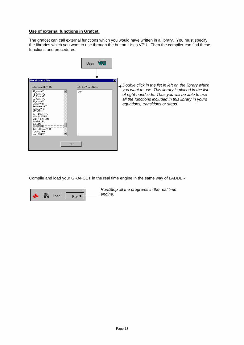
Use of external functions in Grafcet. The grafcet can call external functions which you would have written in a library. You must specify the libraries which you want to use through the button ‘Uses VPU. Then the compiler can find these functions and procedures.
Compile and load your GRAFCET in the real time engine in the same way of LADDER.
Double click in the list in left on the library which you want to use. This library is placed in the list of right-hand side. Thus you will be able to use all the functions included in this library in yours equations, transitions or steps.
Run/Stop all the programs in the real time engine.
Page 19
Introduction to the Pascal Language Background information Completed with Visual I/O, the indispensable complementary tool for the Visual PLC package for all your Man/Machine interfaces, Arsoft can boast of an extensive experience with Pascal Language. The language set out in the IEC 1131 standard is close to the syntax used by Pascal, whose own language existed well before this standard came into being. To keep close to home, Arsoft chose this language to oppose to the definition laid out by the afore-mentioned standard. The Visual PLC user is able to transfer something which has booted the program up in Visual PLC to Visual I/O easily. What’s more, inter-connecting with the Windows system is becoming increasingly sought after and necessitates the putting in place of mechanisms that go beyond those forecasts by standard IEC 1131. You will find both the basic instructions (affectations, Loop For, If/Then/Else, Case etc.) and the possibility of transtyping which have access to external DLLs and many other things. Visual PLC’s Pascal compiler was designed for solving your automation problems. It is not an office automation compiler! Arsoft’s compiler uses powerful algorithms to minimise and optimise the time it takes for you to execute your programs. Visual PLC’s compiler enables the: • Optimisation of the generated code. • Compilation at fast speed. • Incremental compilation. • Direct compilation without transforming the source code. • Single pass compilation. • Compilation with debugging information. • Segmentation of the program in the VPU module that can be performed directly by the real time
engine. Textual commentaries The commentaries are texts ignored by the compiler. Their purpose is to help the user and inform him/her of certain matters which are focused on in greater details. The commentaries are placed in brackets { and } {This is a commentary} or with // characters before the comment. // this is another comment
Page 20
Identifiers In order to write a program, one has to use identifiers that symbolise certain parts of its structure. A Pascal identifier must have a maximum of 63 characters and start with a letter of the alphabet. These characters are letters without accents, numbers and underlined characters. No distinction is made between upper case and lower case letters hence ‘a’ and ‘A’ are identical. The List of accepted characters : a à z A à Z 0 à 9 et _ Here are some useful examples : CallA TwoNumber ReadNextRecord Call_2 Here are some bad examples: August { Letter with an accent } 1_Call { Starts with a number } Call-Sp { The hyphen is forbidden } Warning : One must not use reserved words or names of procedures and
functions defined by the language as identifiers. Declarations The declarations comprise 2 main elements: the constants (CONST) and the variables (VAR) . These 2 elements can be written in any order and repeated several times. The declarations are grouped together under one of the 2 afore-mentioned elements, which play a lead role. Each declaration ends with a semi-colon. Example : CONST MaxNum = 1235; Chaine = ‘Bonjour’; Var I,J : Integer; {*** not initialize variable **} K,L : Word=1; {*** initialize variable**}
Page 21
Boolean types : In automation mode the byte denomination corresponds to a Boolean in Visual PLC. However, the bit of a byte is also a part of Visual PLC’s Booleans. The Boolean types can only take 2 pre-defined values, FALSE and TRUE. The ordinal values of FALSE and TRUE are 0 and 1 respectively. Output: BOOLEAN If I0 is an Integer, I0.4 is a Boolean in Visual PLC. Arrays An array is a structure that groups elements of the same type together. The example below shows the
syntax of the arrays: Cash : Array [1..4] Of REAL SEMESTRE : Array [1..6] Of BOOLEAN To access to an element of an array you pass via an indexation, for example, Cash[2]. In this case, you work with the second real number of the Cash array. Character strings A character string is a series of characters whose number can vary from 1 to 255. You can assimilate the string to an array of 256 elements. The first element, indice 0, contains the useful length of the string. The example below of syntax of a typical string : Chaine : STRING Ich : STRING ='Automatic'; {** initialize string **} The 0 index returns the length of the string which is an ASCII value.. A character string is written between two apostrophes. If an apostrophe appears in the component of the character string, a back up copy is taken. Example : Var
Msg : STRING; BEGIN Msg : = 'Bonjour'; Msg := 'Today' : END;
To guage the length of a string, Pascal Length (Msg) has come up with a pre-defined facility for just this purpose. In addition, you can also use the ordinal value of the 0 indice belonging to the Ord string (Msg[0]) which returns 7 in the ‘Hello’ example. If you group a string of 200 characters and another of 100 together, the last 45 characters will be lost.
Page 22
The operators Below are listed all the keyboard operators : Not, /, Mod, And, Shl, Shr +, -, Or, Xor, =, <>, >, <, <=, >= Some of them will have the weighty task to carry out several sorts of different operations. The arithmetical operators The arithmetical operators carry out the 4 basic operations on numbers; addition, subtraction, multiplication and division, and are all represented by their usual symbols with the exception of the multiplication task which is represented by an asterisk *. Another operator is used for dividing: the MOD operator, which oversees the rest of the division operation. Visual PLC simplifies arithmetical calculations as far as possible. You can freely mix types. Similarly, the division of a 32-bit byte (Integer) by a Real is possible. The compiler automatically transforms the arithmetical expression when it finds different types in an equation. Pay attention to rounding up in this case! Dividing by 0 will not work in the system since it will just come back with the result 0. Character string operator The only operating symbol used by the character strings is the +, whose job it is to group strings, characters and compact chains together. In each case, the regrouping of strings is limited to a length of 255 characters. Below is an example: TS :='Visual PLC'+' Real Time'; The result in TS is: ‘Visual PLC Real Time’ To test or affect an element from a character string, use the following syntax. String[X] Example: If TS[1]='v' Then Ts[1]:='V';
Page 23
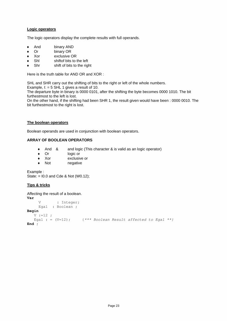
Logic operators The logic operators display the complete results with full operands. ♦ And binary AND ♦ Or binary OR ♦ Xor exclusive OR ♦ Shl shiftof bits to the left ♦ Shr shift of bits to the right Here is the truth table for AND OR and XOR : SHL and SHR carry out the shifting of bits to the right or left of the whole numbers. Example, I: = 5 SHL 1 gives a result of 10. The departure byte in binary is 0000 0101, after the shifting the byte becomes 0000 1010. The bit furthestmost to the left is lost. On the other hand, if the shifting had been SHR 1, the result given would have been : 0000 0010. The bit furthestmost to the right is lost. The boolean operators Boolean operands are used in conjunction with boolean operators. ARRAY OF BOOLEAN OPERATORS
♦ And & and logic (This character & is valid as an logic operator) ♦ Or logic or ♦ Xor exclusive or ♦ Not negative
Example : State: = I0.0 and Cde & Not (W0.12); Tips & tricks Affecting the result of a boolean. Var V : Integer; Egal : Boolean ; Begin V :=12 ; Egal : = (V=12); {*** Boolean Result affected to Egal **} End ;
Page 24
The Relational Operators The number of relational operators on sets are 4. Array of all the relational operators combined ♦ = equals. ♦ <> different to. ♦ <= less than or equal to. ♦ >= more than or equal to. Instructions The instructions are actions executed inside of the block in order of programming. You can distinguish between simple instructions: Affectations, procedure and function calls. You can also distinguish between composed instructions: IF, CASE, REPEAT, WHILE, FOR. Simple Instructions The simple instructions are one of the followings: • Affectation instructions. • Procedure and function instructions. Affectations The instruction of affectation:= is allowed to load a variable by a new value. The former is an expression of a compatible type with the variable. Here is some examples: TS :=’Hello’ ; I :=12 ; R :=12.3 ; Call of a procedure Such an instruction executes a procedure. The former is appointed by its identifier and, possibly, by a list of arguments (formal parameters). Here is the syntax: If Button Then Initialize; The number and the type of parameters passed in arguments of procedure have to correspond to these describes called in the heading of the procedure.
Page 25
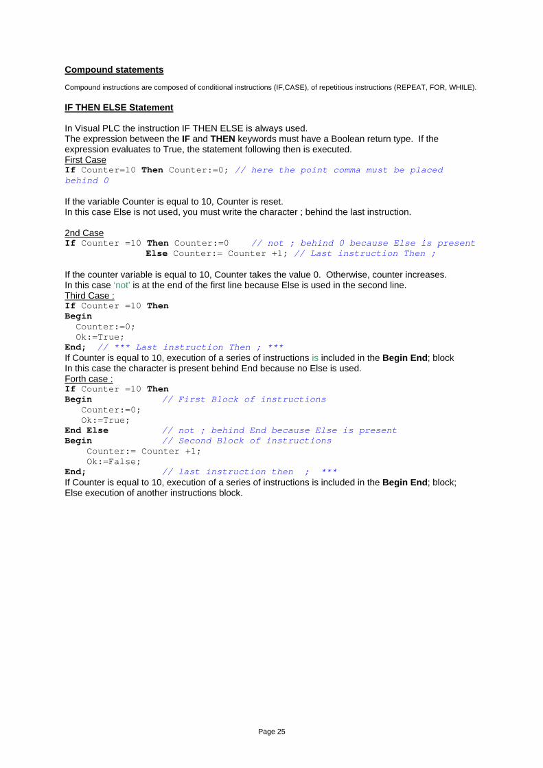
Compound statements Compound instructions are composed of conditional instructions (IF,CASE), of repetitious instructions (REPEAT, FOR, WHILE). IF THEN ELSE Statement In Visual PLC the instruction IF THEN ELSE is always used. The expression between the IF and THEN keywords must have a Boolean return type. If the expression evaluates to True, the statement following then is executed. First Case If Counter=10 Then Counter:=0; // here the point comma must be placed behind 0 If the variable Counter is equal to 10, Counter is reset. In this case Else is not used, you must write the character ; behind the last instruction. 2nd Case If Counter =10 Then Counter:=0 // not ; behind 0 because Else is present Else Counter:= Counter +1; // Last instruction Then ; If the counter variable is equal to 10, Counter takes the value 0. Otherwise, counter increases. In this case ‘not’ is at the end of the first line because Else is used in the second line. Third Case : If Counter =10 Then Begin Counter:=0; Ok:=True; End; // *** Last instruction Then ; *** If Counter is equal to 10, execution of a series of instructions is included in the Begin End; block In this case the character is present behind End because no Else is used. Forth case : If Counter =10 Then Begin // First Block of instructions Counter:=0; Ok:=True; End Else // not ; behind End because Else is present Begin // Second Block of instructions Counter:= Counter +1; Ok:=False; End; // last instruction then ; *** If Counter is equal to 10, execution of a series of instructions is included in the Begin End; block; Else execution of another instructions block.
Page 26
REPEAT UNTIL Statement The repeat statement is used to execute a statement until a certain condition is reached. The statement will be executed at least once. The statements between repeat and until are executed until the Boolean expression is True. Example: Repeat Counter:= Counter+1; Ok:=False; Until Counter =10; // *** ; needed The next syntax is correct but useless. The Begin and the End are useless. Repeat Begin Counter:= Counter+1; Ok:=False; End; Until Counter:=10; // *** ; needed The instruction Repeat Until is the neighbour of the instruction While Do. However, in Repeat Until the block of instructions is executed at least once, because the test is at the end of the block. WHILE DO Statement A while statement contains an expression that controls the repeated execution of a singular or compound statement. The syntax is WHILE Condition is True DO Something; The expression is evaluated before the statement is executed, so if the expression is False at the beginning, the statement is not executed. Example: While Counter <10 Do Begin Counter:= Counter +1; Ok:=False; End; // *** ; needed CASE OF Statement If one of the case constant values matches the value of the expression, the statement that follows this constant is executed After that, the program continues after the final end. If none of the case constants match the expression value, the statement after the else keyword is executed Example : Begin Case Indice of 1 : Order:=11; 2 : Order:=22; 3 : Order:=11;
100 : Order:=100; Else Order:=0; // *** Else is optional End; End; IF indice=1 then order receive the value 1.
Page 27
FOR TO /DOWNTO Statement A for loop is used in case one wants to calculate something a fixed number of times Statement can be a compound statement. When this statement is encountered, the control variable is initialized with the initial value, and is compared with the final value. What happens next depends on whether to or downto is used In the case To is used, if the initial value is larger than the final value, Statement will never be executed. In the case DownTo is used, if the initial value is less than the final value, Statement will never be executed. The syntax is : For .. To/Downto … Do Example: For I :=1 to 10 do Somme:=Somme+Tablo[I]; This loop goes from 1 to 10. Example: For I :=10 DownTo 1 do Somme:=Somme+Tablo[I]; This loop goes from 10 to 1.
Page 28
Procedures and functions Procedure statements are called subroutines. There are different possibilities for procedure calls. They are necessary for the good comprehension of a program and to their maintenance. Procedures and functions can be declared in the VPU library part and can use other functions in other VPU Structure A procedure is a program part that performs a specific action, often based on a set of parameters. A function is a program part that computes and returns a value. Procedures and functions are constituted of a heading and a block. The heading is constituted by reserved word PROCEDURE or FUNCTION, followed by an identifier, possibly of a list of arguments in parentheses, and for functions the type of the result returned. Here is the syntax:
Procedure MyProc1( Element : String) ; Procedure MyProc2( Var Element : String) ; Function MyFunc ( Number : Real) : Boolean ;
In the case of the MyProc1 procedure, the variable Element is sent to the procedure. This Variable can be only read. In the case of the MyProc2 procedure, the variable Element is sent to the procedure. This Variable can be read and written. In the case of the MyFunc function, the variable Number is sent to the function. This variable can be read but not written. This function returns a Boolean that can be tested or not by the instruction has called it. Returns a result from a Function : A function returns a typed result ( Boolean, Real, Etc..). This result is a variable created by the function itself. This result variable is a reserved word of the Pascal language named RESULT. Example: Function Addition ( V1,V2 : Real) : Real ; Begin Result :=V1+V2 ; End ; Result: is the result variable of the function. In the case below Total will receive the result of the Addition function in return. Total :=Addition(10,20) ;
Page 29
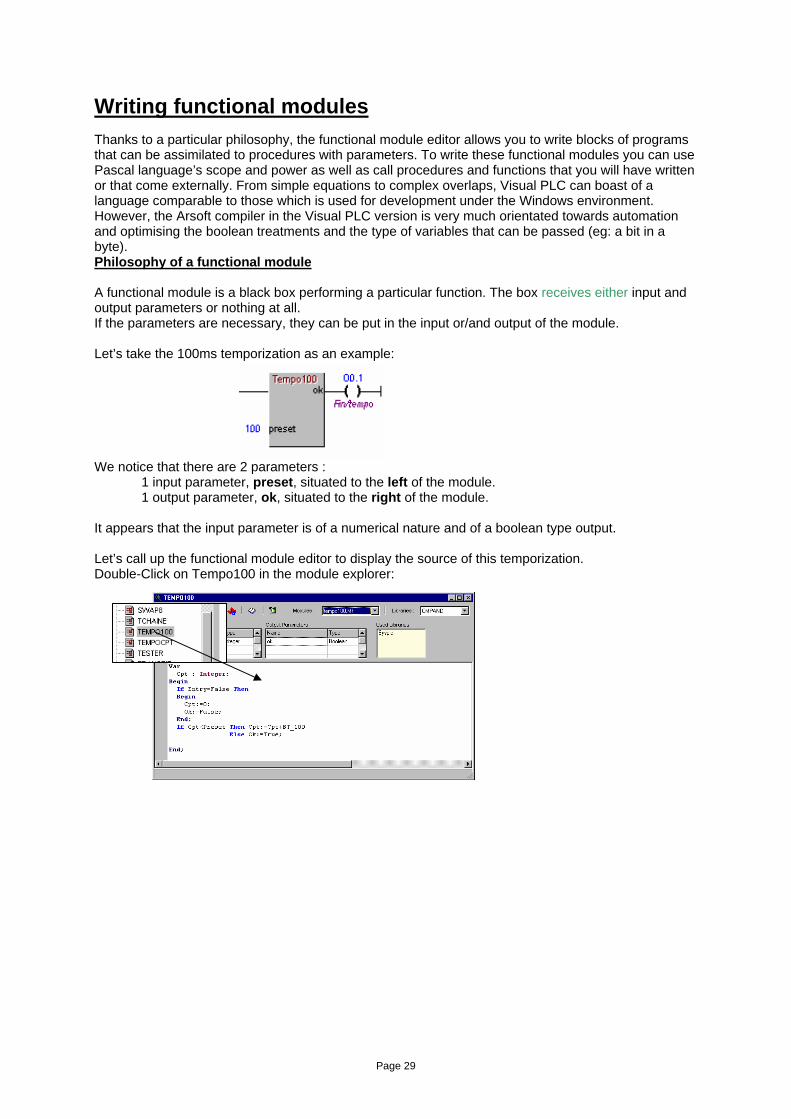
Writing functional modules Thanks to a particular philosophy, the functional module editor allows you to write blocks of programs that can be assimilated to procedures with parameters. To write these functional modules you can use Pascal language’s scope and power as well as call procedures and functions that you will have written or that come externally. From simple equations to complex overlaps, Visual PLC can boast of a language comparable to those which is used for development under the Windows environment. However, the Arsoft compiler in the Visual PLC version is very much orientated towards automation and optimising the boolean treatments and the type of variables that can be passed (eg: a bit in a byte). Philosophy of a functional module A functional module is a black box performing a particular function. The box receives either input and output parameters or nothing at all. If the parameters are necessary, they can be put in the input or/and output of the module. Let’s take the 100ms temporization as an example: We notice that there are 2 parameters :
1 input parameter, preset, situated to the left of the module. 1 output parameter, ok, situated to the right of the module.
It appears that the input parameter is of a numerical nature and of a boolean type output. Let’s call up the functional module editor to display the source of this temporization. Double-Click on Tempo100 in the module explorer:
The source code is display.
Page 30
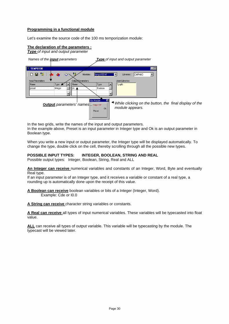
Programming in a functional module Let’s examine the source code of the 100 ms temporization module: The declaration of the parameters : Type of input and output parameter Names of the input parameters Type of input and output parameter
In the two grids, write the names of the input and output parameters. In the example above, Preset is an input parameter in Integer type and Ok is an output parameter in Boolean type. When you write a new input or output parameter, the Integer type will be displayed automatically. To change the type, double click on the cell, thereby scrolling through all the possible new types. POSSIBLE INPUT TYPES: INTEGER, BOOLEAN, STRING AND REAL Possible output types: Integer, Boolean, String, Real and ALL An Integer can receive numerical variables and constants of an Integer, Word, Byte and eventually Real type. If an input parameter is of an Integer type, and it receives a variable or constant of a real type, a rounding up is automatically done upon the receipt of this value. A Boolean can receive boolean variables or bits of a Integer (Integer, Word). Example: Cde or I0.0
A String can receive character string variables or constants. A Real can receive all types of input numerical variables. These variables will be typecasted into float value. ALL can receive all types of output variable. This variable will be typecasting by the module. The typecast will be viewed later.
While clicking on the button, the final display of the module appears.
Output parameters’ names
Page 31
Test equation in Ladder validating the functional module It is useful to test the validating conditions of the functional module. In other words, it is to be able to know the result of the Ladder linked to the module. The pre-defined variable ENTRY in Boolean type has the same state as the Ladder connected to the module. If ENTRY is True, that means that the Ladder linked to the module is true. Let’s analyse the source code of the temporization Var Cpt : Integer; Begin If Entry=False Then If ENTRY is false(0), the Begin output bit is reset as well as Cpt:=0; the internal counter. OK:=FALSE; End; If Cpt<Preset Then Cpt:=Cpt+BT_100 If the internal counter is
Else Ok:=True; less than the parameter value, End; add the elapsed time. If not, the output bit is True(1). We can see that the module needs a saved internal variable. This variable is declared before the beginning of the program. In the case of a functional module, all variables declared in this way are saved when the program leaves the module. We can declare all types of local variables (arrays, strings etc) in the module. System Variables ENTRY (Boolean) Has the same state of the Ladder linked to the
module. BT_100 (Integer) Is true every 100ms for one cycle. START_PROG (Boolean) Shows the first program cycle. Attentions: in a functional module, the local variables in the module are not initialized. We initialize these variables with the Start_Prog variable. Example: If Start_Prog Then Cpt: =0; To quit the functional module The EXIT instruction allows you to leave a module without executing the rest of the program module. Example: If Entry=False Then
Begin Cpt: =0;
Ok: =False; Exit; {exit the module here } End;
Page 32
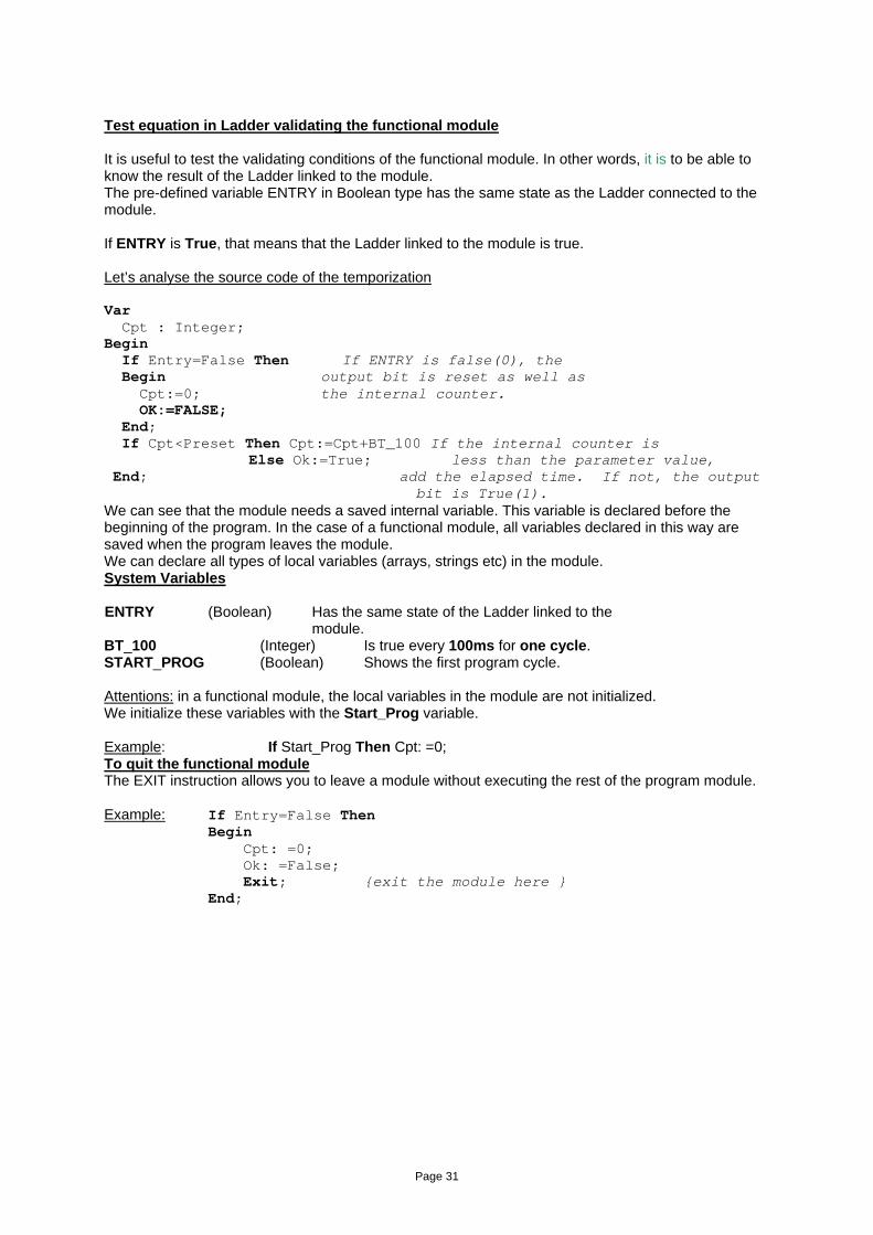
Examples of functional modules Simple counter: Let’s consider a module which has only one output Integer parameter named Compte and we want to count the pulses of the Ladder linked to this module. If the program was written as follows: Begin If Entry Then Compte: =Compte+1; End; The variable Compte will be increased for every cycle. You must insert a rising edge by declaring a Boolean used as a rising edge. Var Edge: Boolean; {Internal rising edge bit saved} Begin If Entry and Not(Edge) Then {If the ENTRY variable is true and the Edg Begin variable is false, then the variable Compte increases.} Compte: =Compte+1; Edge: =True; End; If Not(Entry) Then Edge:=False; { If the ENTRY variable is false, the Edge variable is
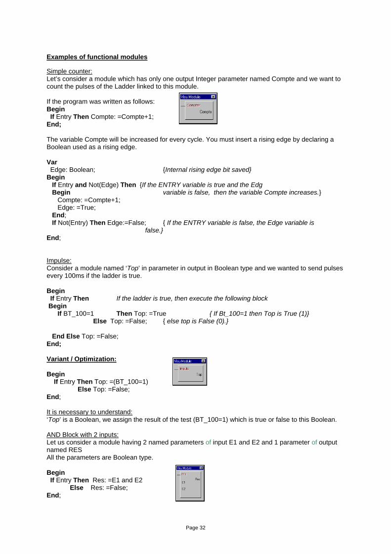
false.} End; Impulse: Consider a module named ‘Top’ in parameter in output in Boolean type and we wanted to send pulses every 100ms if the ladder is true. Begin If Entry Then If the ladder is true, then execute the following block Begin If BT_100=1 Then Top: =True { If Bt_100=1 then Top is True (1)} Else Top: =False; { else top is False (0).} End Else Top: =False; End; Variant / Optimization: Begin If Entry Then Top: =(BT_100=1) Else Top: =False; End; It is necessary to understand: ‘Top’ is a Boolean, we assign the result of the test (BT_100=1) which is true or false to this Boolean. AND Block with 2 inputs: Let us consider a module having 2 named parameters of input E1 and E2 and 1 parameter of output named RES All the parameters are Boolean type. Begin If Entry Then Res: =E1 and E2 Else Res: =False; End;
Page 33
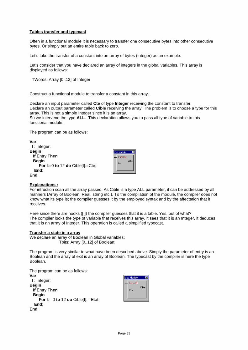
Tables transfer and typecast Often in a functional module it is necessary to transfer one consecutive bytes into other consecutive bytes. Or simply put an entire table back to zero. Let’s take the transfer of a constant into an array of bytes (Integer) as an example. Let’s consider that you have declared an array of integers in the global variables. This array is displayed as follows: TWords: Array [0..12] of Integer Construct a functional module to transfer a constant in this array. Declare an input parameter called Cte of type Integer receiving the constant to transfer. Declare an output parameter called Cible receiving the array. The problem is to choose a type for this array. This is not a simple Integer since it is an array. So we intervene the type ALL. This declaration allows you to pass all type of variable to this functional module. The program can be as follows: Var I : Integer; Begin If Entry Then Begin For I:=0 to 12 do Cible[I]:=Cte; End; End; Explanations : For intruction scan all the array passed. As Cible is a type ALL parameter, it can be addressed by all manners (Array of Boolean, Real, string etc.). To the compilation of the module, the compiler does not know what its type is; the compiler guesses it by the employed syntax and by the affectation that it receives. Here since there are hooks ([I]) the compiler guesses that it is a table. Yes, but of what? The compiler looks the type of variable that receives this array, it sees that it is an Integer, it deduces that it is an array of Integer. This operation is called a simplified typecast. Transfer a state in a array We declare an array of Boolean in Global variables:
Tbits: Array [0..12] of Boolean;
The program is very similar to what have been described above. Simply the parameter of entry is an Boolean and the array of exit is an array of Boolean. The typecast by the compiler is here the type Boolean. The program can be as follows: Var I : Integer; Begin If Entry Then Begin For I: =0 to 12 do Cible[I]: =Etat; End; End;
Page 34
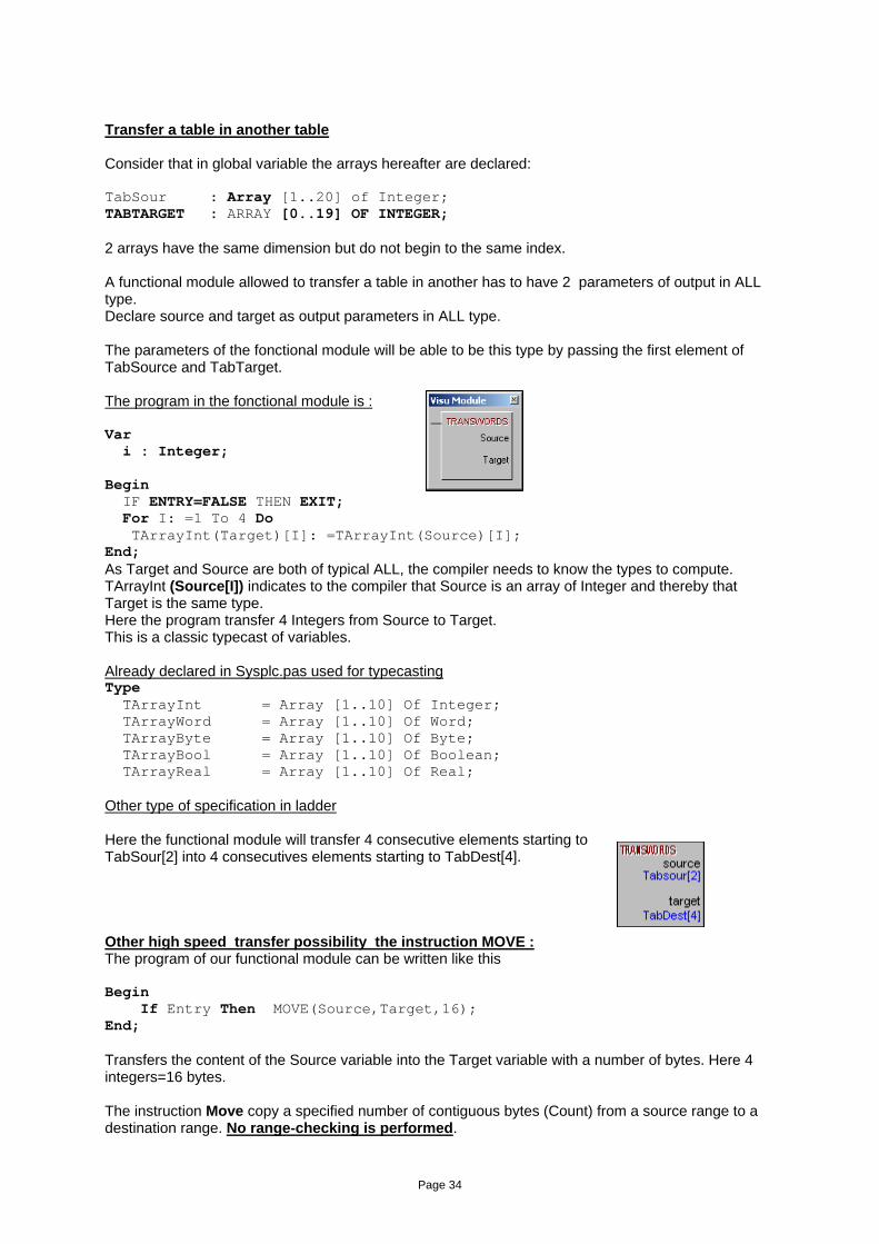
Transfer a table in another table Consider that in global variable the arrays hereafter are declared: TabSour : Array [1..20] of Integer; TABTARGET : ARRAY [0..19] OF INTEGER; 2 arrays have the same dimension but do not begin to the same index. A functional module allowed to transfer a table in another has to have 2 parameters of output in ALL type. Declare source and target as output parameters in ALL type. The parameters of the fonctional module will be able to be this type by passing the first element of TabSource and TabTarget. The program in the fonctional module is : Var i : Integer; Begin IF ENTRY=FALSE THEN EXIT; For I: =1 To 4 Do TArrayInt(Target)[I]: =TArrayInt(Source)[I]; End; As Target and Source are both of typical ALL, the compiler needs to know the types to compute. TArrayInt (Source[I]) indicates to the compiler that Source is an array of Integer and thereby that Target is the same type. Here the program transfer 4 Integers from Source to Target. This is a classic typecast of variables. Already declared in Sysplc.pas used for typecasting Type TArrayInt = Array [1..10] Of Integer; TArrayWord = Array [1..10] Of Word; TArrayByte = Array [1..10] Of Byte; TArrayBool = Array [1..10] Of Boolean; TArrayReal = Array [1..10] Of Real; Other type of specification in ladder Here the functional module will transfer 4 consecutive elements starting to TabSour[2] into 4 consecutives elements starting to TabDest[4]. Other high speed transfer possibility the instruction MOVE : The program of our functional module can be written like this Begin If Entry Then MOVE(Source,Target,16); End; Transfers the content of the Source variable into the Target variable with a number of bytes. Here 4 integers=16 bytes. The instruction Move copy a specified number of contiguous bytes (Count) from a source range to a destination range. No range-checking is performed.
Page 35
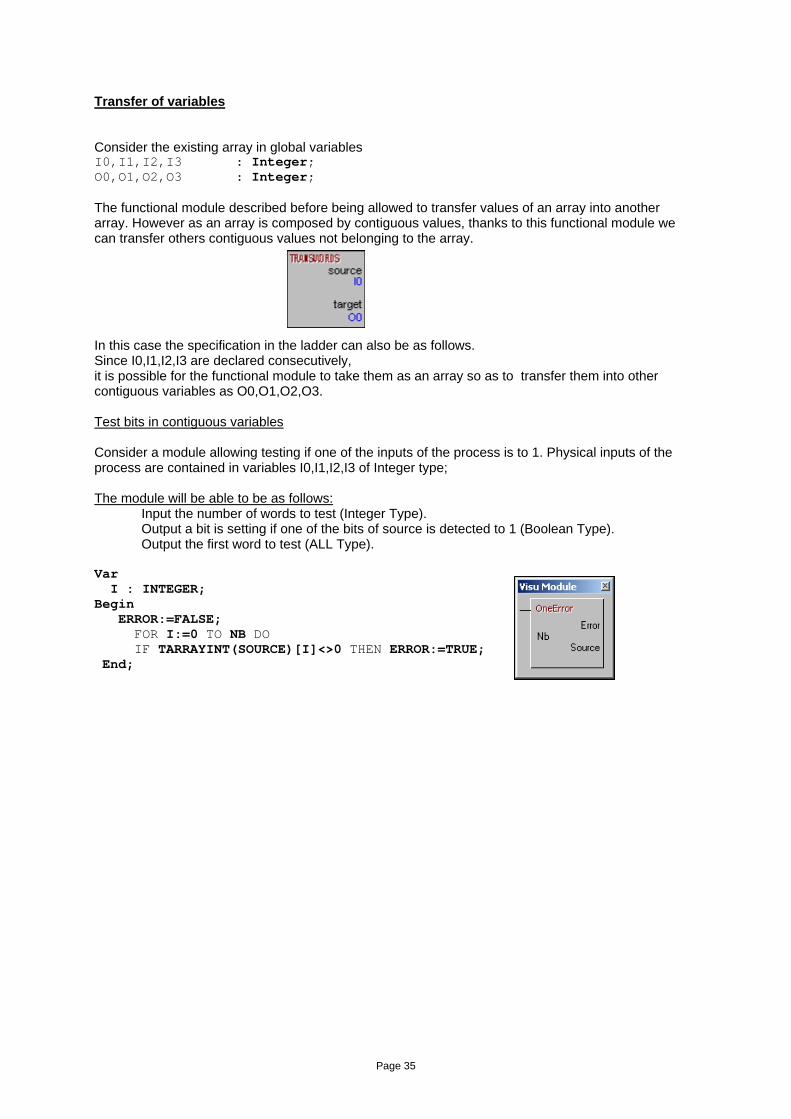
Transfer of variables Consider the existing array in global variables I0,I1,I2,I3 : Integer; O0,O1,O2,O3 : Integer; The functional module described before being allowed to transfer values of an array into another array. However as an array is composed by contiguous values, thanks to this functional module we can transfer others contiguous values not belonging to the array. In this case the specification in the ladder can also be as follows. Since I0,I1,I2,I3 are declared consecutively, it is possible for the functional module to take them as an array so as to transfer them into other contiguous variables as O0,O1,O2,O3. Test bits in contiguous variables Consider a module allowing testing if one of the inputs of the process is to 1. Physical inputs of the process are contained in variables I0,I1,I2,I3 of Integer type; The module will be able to be as follows:
Input the number of words to test (Integer Type). Output a bit is setting if one of the bits of source is detected to 1 (Boolean Type). Output the first word to test (ALL Type).
Var I : INTEGER; Begin ERROR:=FALSE; FOR I:=0 TO NB DO IF TARRAYINT(SOURCE)[I]<>0 THEN ERROR:=TRUE; End;
Page 36
Shift bits to left in consecutives words. Consider a module allowed to shift to the left all the bits of contiguous words. The program could be as follows: Var I : Integer; Edge : Boolean; Begin If Entry and Not(Edge) Then Begin For i:=3 Downto 0 do Begin
TArrayInt(Source)[I]:=TArrayInt(Source)[I] Shl 1; If I>0 Then If Source[I-1].31 Then Source[I].0:=True; End; Edge:=True; End; If Entry=False Then Edge:=False; End; Explanations : If Entry and Not(Edge) Then Allow you to do an edge when the connected Ladder is true. For i: =3 Downto 0 do Loop starting from 3 downto 0. Start on the last Integer to goto the first integer. TArrayInt(Source)[I]:=TArrayInt(Source)[I] Shl 1; All the bits of the word in progress are shift of one position to the left. If I>0 Then If Source[I-1].31 Then Source[I].0:=True; If the pointer is not on the first word, we take the last bit of the preceding word; that report in the first bit of the word in progress. Here one processes words of 32 bits.
Page 37
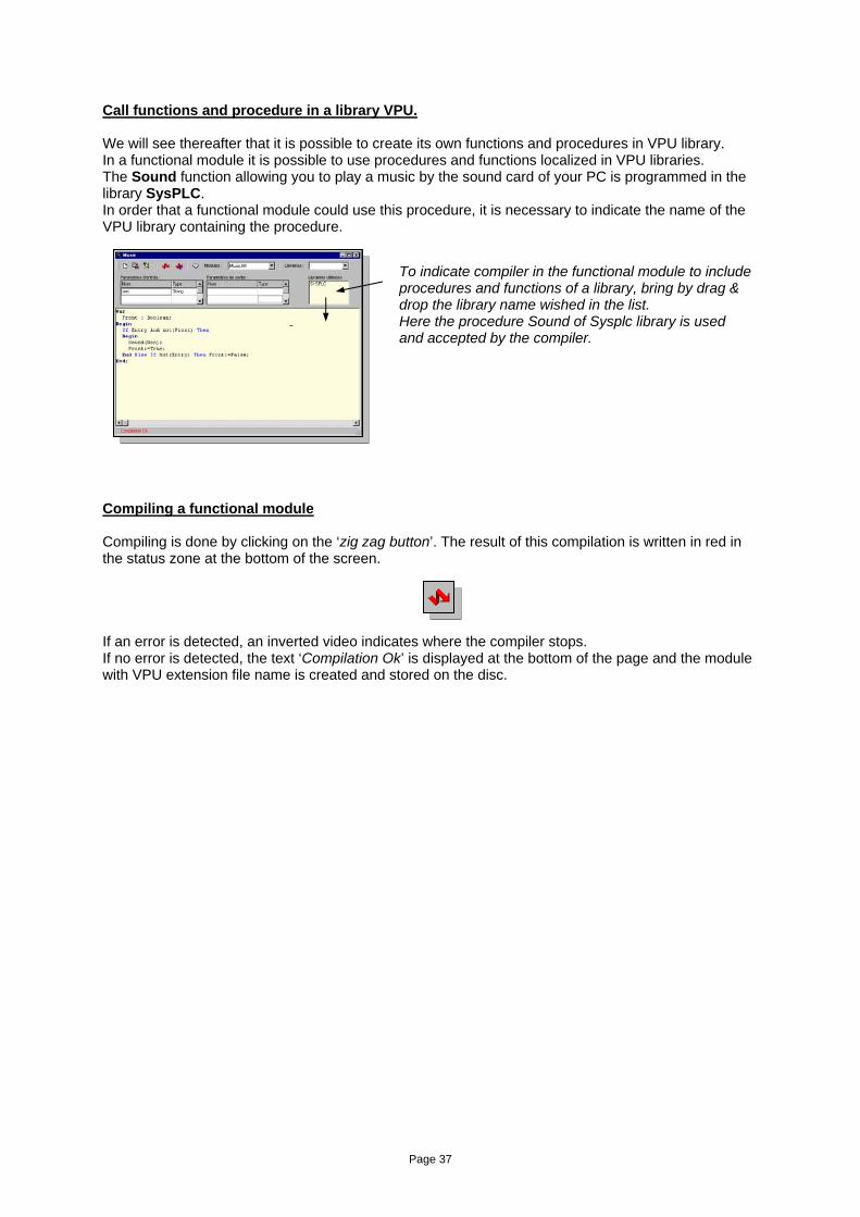
Call functions and procedure in a library VPU. We will see thereafter that it is possible to create its own functions and procedures in VPU library. In a functional module it is possible to use procedures and functions localized in VPU libraries. The Sound function allowing you to play a music by the sound card of your PC is programmed in the library SysPLC. In order that a functional module could use this procedure, it is necessary to indicate the name of the VPU library containing the procedure.
Compiling a functional module Compiling is done by clicking on the ‘zig zag button’. The result of this compilation is written in red in the status zone at the bottom of the screen. If an error is detected, an inverted video indicates where the compiler stops. If no error is detected, the text ‘Compilation Ok’ is displayed at the bottom of the page and the module with VPU extension file name is created and stored on the disc.
To indicate compiler in the functional module to include procedures and functions of a library, bring by drag & drop the library name wished in the list. Here the procedure Sound of Sysplc library is used and accepted by the compiler.
Page 38
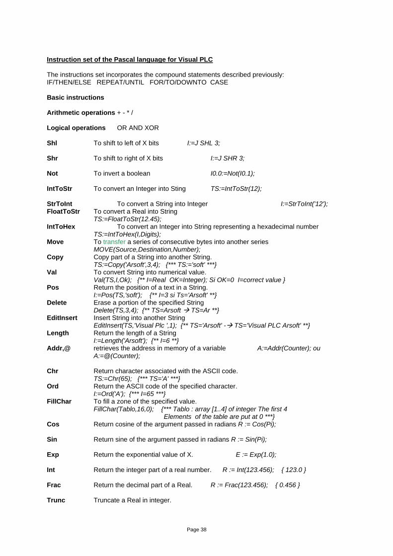
Instruction set of the Pascal language for Visual PLC The instructions set incorporates the compound statements described previously: IF/THEN/ELSE REPEAT/UNTIL FOR/TO/DOWNTO CASE Basic instructions Arithmetic operations + - * / Logical operations OR AND XOR Shl To shift to left of X bits I:=J SHL 3; Shr To shift to right of X bits I:=J SHR 3; Not To invert a boolean I0.0:=Not(I0.1); IntToStr To convert an Integer into Sting TS:=IntToStr(12); StrToInt To convert a String into Integer I:=StrToInt('12'); FloatToStr To convert a Real into String TS:=FloatToStr(12.45); IntToHex To convert an Integer into String representing a hexadecimal number TS:=IntToHex(I,Digits); Move To transfer a series of consecutive bytes into another series
MOVE(Source,Destination,Number); Copy Copy part of a String into another String. TS:=Copy('Arsoft',3,4); {*** TS:='soft' ***} Val To convert String into numerical value. Val(TS,I,Ok); {** I=Real OK=Integer); Si OK=0 I=correct value } Pos Return the position of a text in a String. I:=Pos(TS,'soft'); {** I=3 si Ts='Arsoft' **} Delete Erase a portion of the specified String Delete(TS,3,4); {** TS=Arsoft TS=Ar **} EditInsert Insert String into another String EditInsert(TS,'Visual Plc ',1); {** TS='Arsoft' - TS='Visual PLC Arsoft' **} Length Return the length of a String I:=Length('Arsoft'); {** I=6 **} Addr,@ retrieves the address in memory of a variable A:=Addr(Counter); ou
A:=@(Counter); Chr Return character associated with the ASCII code. TS:=Chr(65); {*** TS='A' ***} Ord Return the ASCII code of the specified character. I:=Ord('A'); {*** I=65 ***} FillChar To fill a zone of the specified value. FillChar(Tablo,16,0); {*** Tablo : array [1..4] of integer The first 4
Elements of the table are put at 0 ***} Cos Return cosine of the argument passed in radians R := Cos(Pi); Sin Return sine of the argument passed in radians R := Sin(Pi); Exp Return the exponential value of X. E := Exp(1.0); Int Return the integer part of a real number. R := Int(123.456); { 123.0 } Frac Return the decimal part of a Real. R := Frac(123.456); { 0.456 } Trunc Truncate a Real in integer.
Page 39
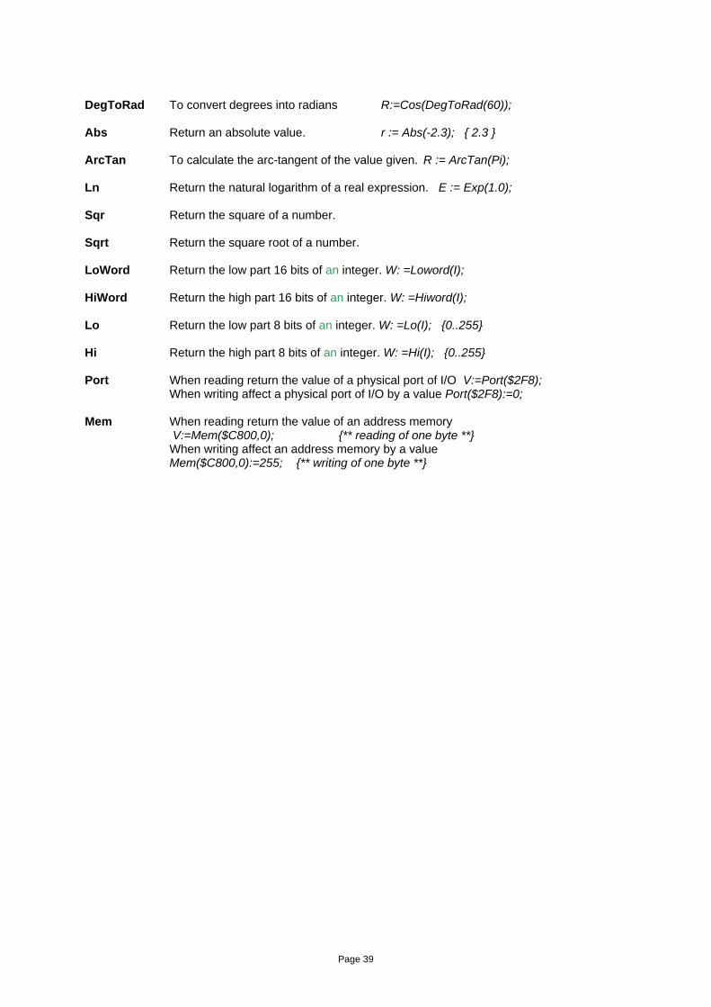
DegToRad To convert degrees into radians R:=Cos(DegToRad(60)); Abs Return an absolute value. r := Abs(-2.3); { 2.3 } ArcTan To calculate the arc-tangent of the value given. R := ArcTan(Pi); Ln Return the natural logarithm of a real expression. E := Exp(1.0); Sqr Return the square of a number. Sqrt Return the square root of a number. LoWord Return the low part 16 bits of an integer. W: =Loword(I); HiWord Return the high part 16 bits of an integer. W: =Hiword(I); Lo Return the low part 8 bits of an integer. W: =Lo(I); {0..255} Hi Return the high part 8 bits of an integer. W: =Hi(I); {0..255} Port When reading return the value of a physical port of I/O V:=Port($2F8); When writing affect a physical port of I/O by a value Port($2F8):=0; Mem When reading return the value of an address memory
V:=Mem($C800,0); {** reading of one byte **} When writing affect an address memory by a value
Mem($C800,0):=255; {** writing of one byte **}
Page 40
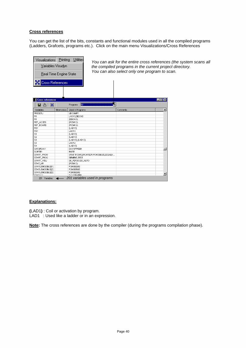
Cross references You can get the list of the bits, constants and functional modules used in all the compiled programs (Ladders, Grafcets, programs etc.). Click on the main menu Visualizations/Cross References
Explanations: (LAD1) : Coil or activation by program. LAD1 : Used like a ladder or in an expression. Note: The cross references are done by the compiler (during the programs compilation phase).
You can ask for the entire cross references (the system scans all the compiled programs in the current project directory. You can also select only one program to scan.
201 variables used in programs
Page 41
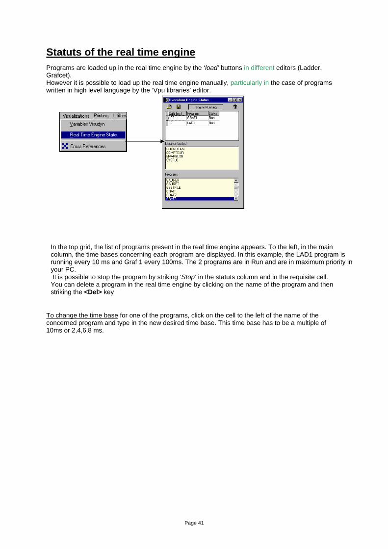
Statuts of the real time engine Programs are loaded up in the real time engine by the ‘load’ buttons in different editors (Ladder, Grafcet). However it is possible to load up the real time engine manually, particularly in the case of programs written in high level language by the ‘Vpu libraries’ editor. To change the time base for one of the programs, click on the cell to the left of the name of the concerned program and type in the new desired time base. This time base has to be a multiple of 10ms or 2,4,6,8 ms.
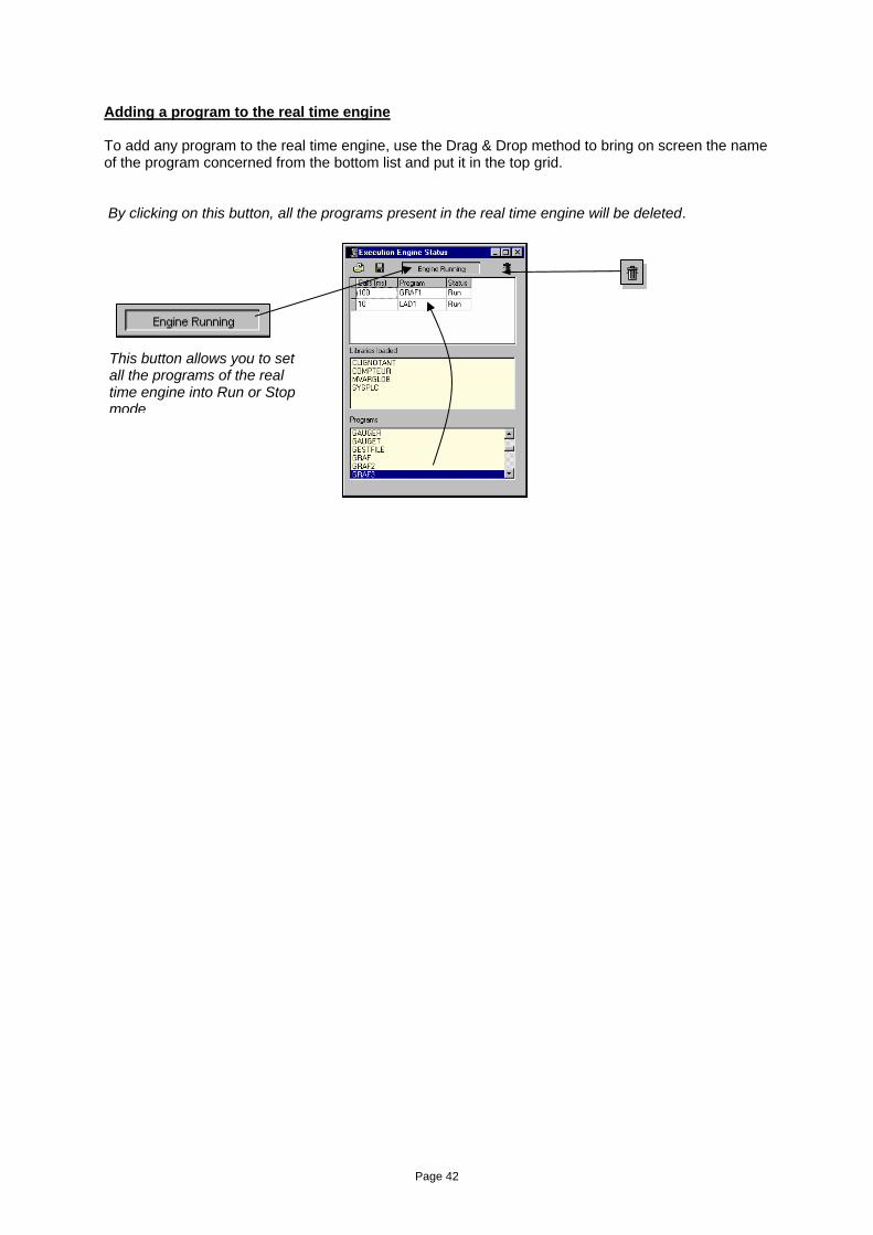
In the top grid, the list of programs present in the real time engine appears. To the left, in the main column, the time bases concerning each program are displayed. In this example, the LAD1 program is running every 10 ms and Graf 1 every 100ms. The 2 programs are in Run and are in maximum priority in your PC. It is possible to stop the program by striking ‘Stop’ in the statuts column and in the requisite cell. You can delete a program in the real time engine by clicking on the name of the program and then striking the <Del> key
Page 42
Adding a program to the real time engine To add any program to the real time engine, use the Drag & Drop method to bring on screen the name of the program concerned from the bottom list and put it in the top grid. By clicking on this button, all the programs present in the real time engine will be deleted.
This button allows you to set all the programs of the real time engine into Run or Stop mode
Page 43
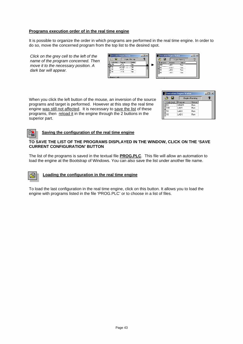
Programs execution order of in the real time engine It is possible to organize the order in which programs are performed in the real time engine. In order to do so, move the concerned program from the top list to the desired spot.
When you click the left button of the mouse, an inversion of the source programs and target is performed. However at this step the real time engine was still not affected. It is necessary to save the list of these programs, then reload it in the engine through the 2 buttons in the superior part.
Saving the configuration of the real time engine
TO SAVE THE LIST OF THE PROGRAMS DISPLAYED IN THE WINDOW, CLICK ON THE ‘SAVE CURRENT CONFIGURATION’ BUTTON The list of the programs is saved in the textual file PROG.PLC. This file will allow an automation to load the engine at the Bootstrap of Windows. You can also save the list under another file name.
Loading the configuration in the real time engine
To load the last configuration in the real time engine, click on this button. It allows you to load the engine with programs listed in the file ‘PROG.PLC’ or to choose in a list of files.
Click on the grey cell to the left of the name of the program concerned. Then move it to the necessary position. A dark bar will appear.
Page 44
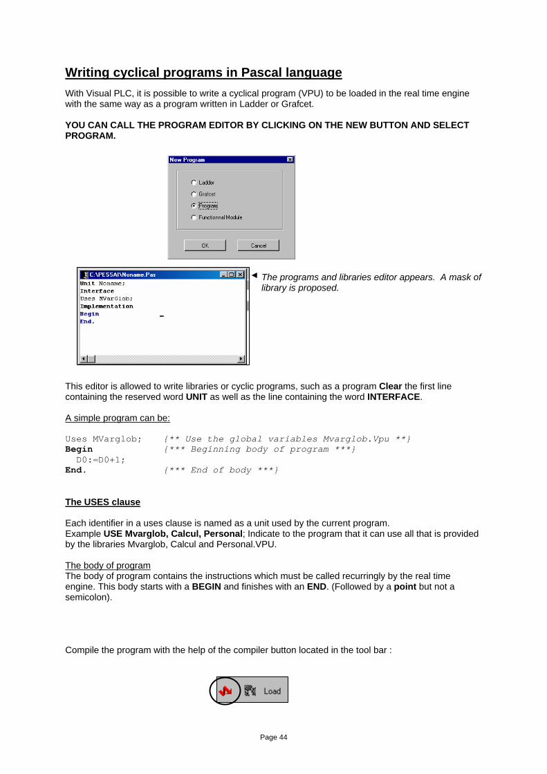
Writing cyclical programs in Pascal language With Visual PLC, it is possible to write a cyclical program (VPU) to be loaded in the real time engine with the same way as a program written in Ladder or Grafcet. YOU CAN CALL THE PROGRAM EDITOR BY CLICKING ON THE NEW BUTTON AND SELECT PROGRAM.
This editor is allowed to write libraries or cyclic programs, such as a program Clear the first line containing the reserved word UNIT as well as the line containing the word INTERFACE. A simple program can be: Uses MVarglob; {** Use the global variables Mvarglob.Vpu **} Begin {*** Beginning body of program ***} D0:=D0+1; End. {*** End of body ***} The USES clause Each identifier in a uses clause is named as a unit used by the current program. Example USE Mvarglob, Calcul, Personal; Indicate to the program that it can use all that is provided by the libraries Mvarglob, Calcul and Personal.VPU. The body of program The body of program contains the instructions which must be called recurringly by the real time engine. This body starts with a BEGIN and finishes with an END. (Followed by a point but not a semicolon). Compile the program with the help of the compiler button located in the tool bar :
The programs and libraries editor appears. A mask of library is proposed.
Page 45
Cyclical programs with interface Normally, a program cannot exchange variables or procedures since it uses these procedures, functions or variables in the unit itself (private). However Visual PLC allows you to mix programs and libraries. Let’s consider that a program increased a word, and we wanted that it belonged to the program and it is also accessible to other externals programs. Let’s examine the code: Interface Var ID0 : Integer; {** variable accessible to external programs **} Implementation {*** Internal program function***} Function Inc( Value : Integer) : Integer; Begin Result:=Value+1; End; {** Body of program ***} Begin ID0:=Inc(ID0); End. We can see that the Uses clause has disappeared because we are not using neither any global variables nor any functions contained in other VPUs. The INTERFACE clause has appeared. This clause allows us to indicate to the compiler that we want to put variables, procedures or functions at the disposal of other programs. In our example, we simply want to put an Integer type variable at the disposal of externals programs. The interface section of a unit is a public part. It determines what is visible and accessible to any program (or other unit) using that unit. The interface section starts at the reserved word interface, which appears after the unit header, and ends with the reserved word implementation. In the unit interface, you declare constants, data types, variables, procedures, and functions. The "bodies" of public procedures and functions are in the implementation section. The IMPLEMENTATION clause allows you to determine the end of the interface and when to start up the code and variables exclusive to the program but not accessible to the others (programs). The implementation part of the unit is where you find the bodies of the procedures and functions that are declared in the interface part of the unit. The implementation part of the unit is a private part. Declarations made here can be used only within this section of the unit.
Page 46
The Inc function allows you to increase a variable. This function can only be used in the program itself because it is contained in the implementation part. Finally, we get to the main part of the program which increased the IDO variable in running program. Only when the noname3 program is loaded up in the real time engine, the IDO variable can now be accessible under the same way as all Mvarglob VPU’s global variables. That is the proof of the mixing of program and library. Normally, a library does not contain a program, or it would not act as library. This case can be useful to control the internal progress since it offers an IDO interface that can be a command according to its state. If you want to allow other programs to have access to the INC function, the program would be written as follows: Interface Var ID0 : Integer; {** accessible variable to any program **} Function Inc( Value : Integer) : Integer; {** This function is now accessible **} Implementation {*** Internal program function ***} Function Inc( Value : Integer) : Integer;
Page 47
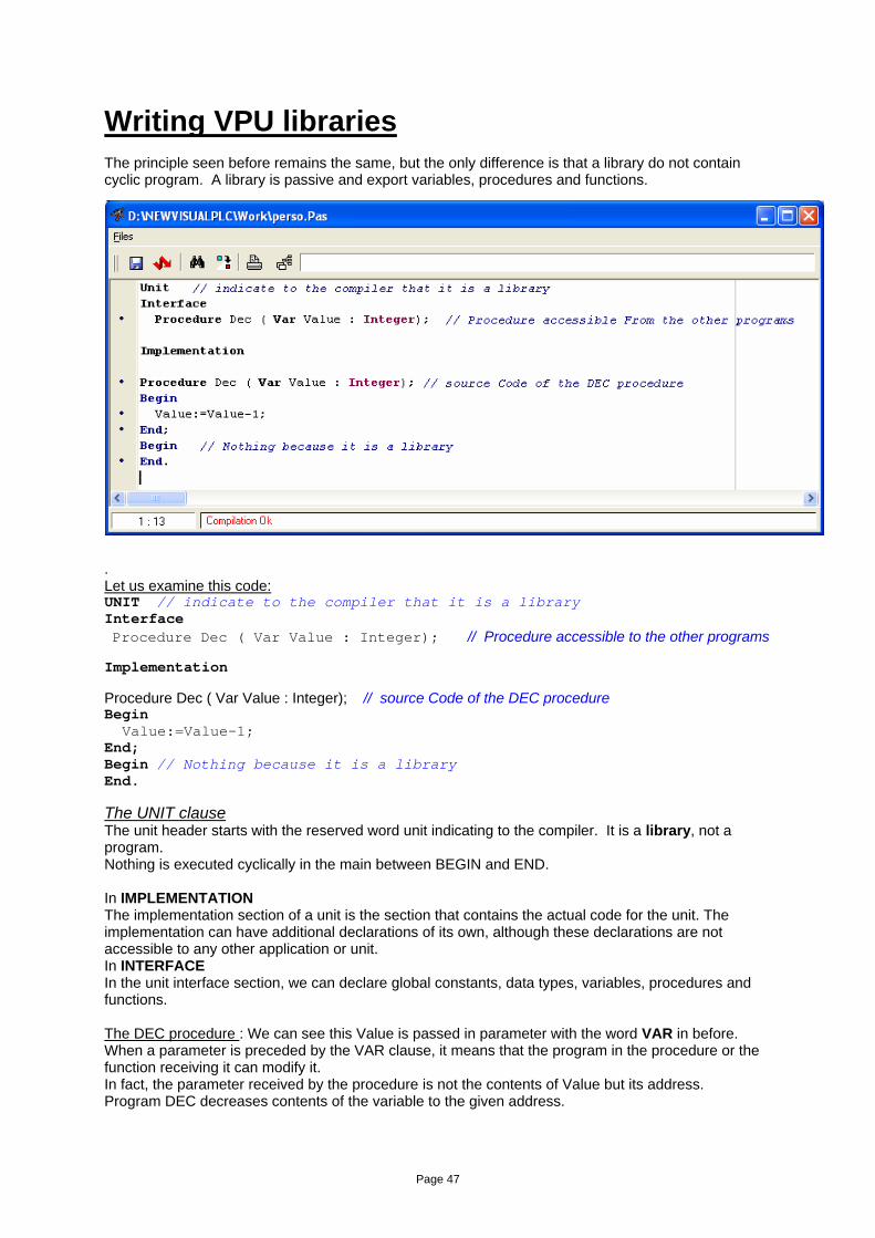
Writing VPU libraries The principle seen before remains the same, but the only difference is that a library do not contain cyclic program. A library is passive and export variables, procedures and functions. Let us imagine a library named PERSONAL containing a procedure DEC. This one decreases a numerical . Let us examine this code: UNIT // indicate to the compiler that it is a library Interface Procedure Dec ( Var Value : Integer); // Procedure accessible to the other programs Implementation Procedure Dec ( Var Value : Integer); // source Code of the DEC procedure Begin Value:=Value-1; End; Begin // Nothing because it is a library End. The UNIT clause The unit header starts with the reserved word unit indicating to the compiler. It is a library, not a program. Nothing is executed cyclically in the main between BEGIN and END. In IMPLEMENTATION The implementation section of a unit is the section that contains the actual code for the unit. The implementation can have additional declarations of its own, although these declarations are not accessible to any other application or unit. In INTERFACE In the unit interface section, we can declare global constants, data types, variables, procedures and functions. The DEC procedure : We can see this Value is passed in parameter with the word VAR in before. When a parameter is preceded by the VAR clause, it means that the program in the procedure or the function receiving it can modify it. In fact, the parameter received by the procedure is not the contents of Value but its address. Program DEC decreases contents of the variable to the given address.
Page 48
Initialization in a library If we want to initialize any data the unit uses, you can add an initialization code to the BEGIN END Section of the unit (Main). When an application uses a unit, the code within the unit's initialization part is called before any other application code runs. Let us examine this code: UNIT // indicate to the compiler that it is a library Interface Procedure Dec ( Var Value : Integer); // Procedure exportable to other programs Implementation Procedure Dec ( Var Value : Integer); // source Code of the DEC procedure Begin Value:=Value-1; End; Procedure Initial; // Internal procedure in the library Begin ….. End; Begin // Initialization of the library (unit) at the start-up time of the application Initial; // Call initial is done only one time End. Passing parameters by values and address When you create procedures and functions, you will have to pass parameters to these procedures and functions. Two solutions are possible. Passing by value Ex: Procedure Test (Value: Integer); Begin End; Begin I:=10; Test(I); // ** sent by value to TEST procedure // here I is always equal to 10 whatever the action in Test End. In this procedure, 'I' cannot be modified by the procedure. We are able to write: If Value = 10 Then … or Counter:=Value; The expression Value:=100 will not have any effect on the variable 'I'. Affecting Value in the procedure modifies the local value but not the original value. A local copy of I is made in the Test procedure. Passing by address Ex : Procedure Test( Var Value : Integer); Begin Value:=Value*2; // *** Modify the value of i * End; Begin I:=10; Test(I); // ** passing to the procedure Test by address * // here I is not equal to 10 it depends on the Test procedure End
Page 49
When passing data to a routine (function or procedure), you can prefix the parameter definition with Var if the variable itself is to be updated by the routine. This allows a caller to pass data to a routine that will be enriched by the routine. Let us take the example of the procedure Inc that allows increasing a variable again. We could write: Procedure INC ( Var Value : Integer); Begin Value:=Value+1; End; Begin Inc(I); // ** Increase I by 1 End. Or writing a function that will do the action: Function INC (Value : Integer) : Integer; Begin Result:=Value+1; End; Begin I:=inc(I); End. Other example: Function Inc(Value : Integer) : Integer; Begin Result:=Value+1; End; Begin R:=1.2; R:=Inc(R); // ** send a real to the function and retrieve result in a real End. The INC Function is normally designed to receive and return an Integer. In this case, the compiler transforms R (a real) into an Integer to adapt to the function and transforms the result returned in integer into real. Passing a variable with no type We can also write: Procedure Inc ( Var Value); Begin Integer(Value):=Integer(Value)+1; End; Here the INC procedure receives a non-typed variable and this by address. It is necessary that the procedure typecasts the variable to exploit it. The INC procedure decides in the example that value is an integer type.
Page 50
Calling procedures and functions in a DLL Visual PLC allows calling procedures and functions located in a dynamic link library DLL. This interface is interesting in the case where you have libraries for scientific cards, or if you decide to enlarge Visual I/O functionalities written under another language (for example in Visual Pascal, C++, Delphi). To use these procedures and functions in a DLL, it is necessary to declare the structure of the function or the procedure in the INTERFACES part of a unit (vpu). The library is used as a link between Visual I/O and the DLL. When you import a routine from a DLL, the procedure or function is imported explicitly by its name. Let us examine the following declaration: Unit Interface Function MessageBeep(Utype : Integer) : Integer; StdCall 'user32.dll'; Implementation Begin End. This VPU library allows getting a new function named MessageBeep. This function is not implemented in the VPU itself but in a DLL named User32.dll. It is necessary to pass a parameter named Utype (Integer type)to the function. StdCall allows specifying to the compiler that it must respect the standard mode for passage of parameters predefined by Microsoft for the 32Bits applications. In case of MessageBeep, the function in User32.dll is also named MessageBeep.
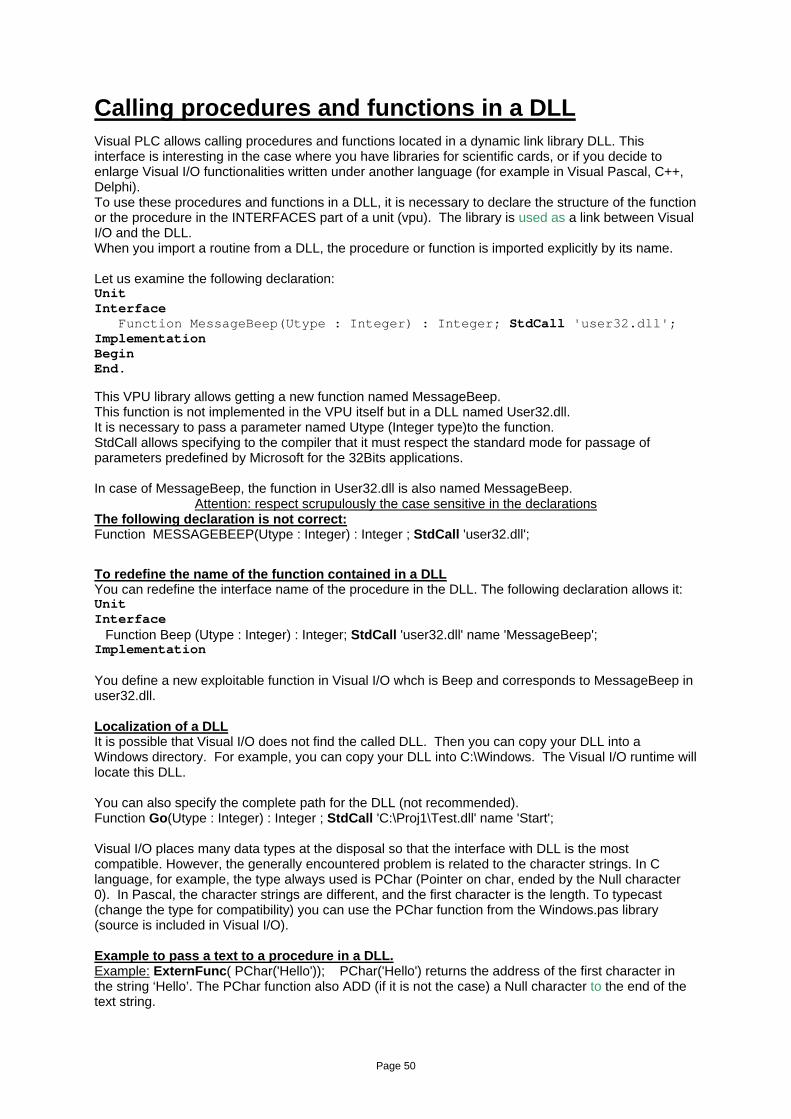
Attention: respect scrupulously the case sensitive in the declarations The following declaration is not correct: Function MESSAGEBEEP(Utype : Integer) : Integer ; StdCall 'user32.dll'; To redefine the name of the function contained in a DLL You can redefine the interface name of the procedure in the DLL. The following declaration allows it: Unit Interface Function Beep (Utype : Integer) : Integer; StdCall 'user32.dll' name 'MessageBeep'; Implementation You define a new exploitable function in Visual I/O whch is Beep and corresponds to MessageBeep in user32.dll. Localization of a DLL It is possible that Visual I/O does not find the called DLL. Then you can copy your DLL into a Windows directory. For example, you can copy your DLL into C:\Windows. The Visual I/O runtime will locate this DLL. You can also specify the complete path for the DLL (not recommended). Function Go(Utype : Integer) : Integer ; StdCall 'C:\Proj1\Test.dll' name 'Start'; Visual I/O places many data types at the disposal so that the interface with DLL is the most compatible. However, the generally encountered problem is related to the character strings. In C language, for example, the type always used is PChar (Pointer on char, ended by the Null character 0). In Pascal, the character strings are different, and the first character is the length. To typecast (change the type for compatibility) you can use the PChar function from the Windows.pas library (source is included in Visual I/O). Example to pass a text to a procedure in a DLL. Example: ExternFunc( PChar('Hello')); PChar('Hello') returns the address of the first character in the string ‘Hello’. The PChar function also ADD (if it is not the case) a Null character to the end of the text string.
Page 51
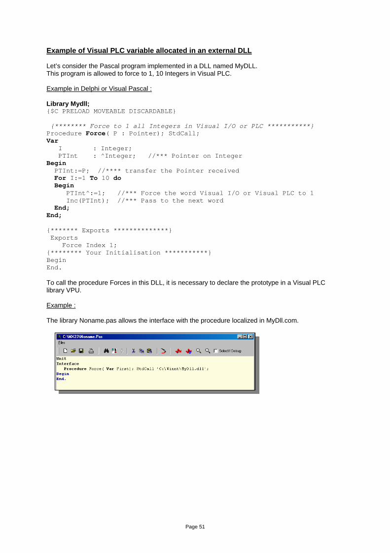
Example of Visual PLC variable allocated in an external DLL Let’s consider the Pascal program implemented in a DLL named MyDLL. This program is allowed to force to 1, 10 Integers in Visual PLC. Example in Delphi or Visual Pascal : Library Mydll; {$C PRELOAD MOVEABLE DISCARDABLE} {******** Force to 1 all Integers in Visual I/O or PLC ***********} Procedure Force( P : Pointer); StdCall; Var I : Integer; PTInt : ^Integer; //*** Pointer on Integer Begin PTInt:=P; //**** transfer the Pointer received For I:=1 To 10 do Begin PTInt^:=1; //*** Force the word Visual I/O or Visual PLC to 1 Inc(PTInt); //*** Pass to the next word End; End; {******* Exports **************} Exports Force Index 1; {******** Your Initialisation ***********} Begin End. To call the procedure Forces in this DLL, it is necessary to declare the prototype in a Visual PLC library VPU. Example : The library Noname.pas allows the interface with the procedure localized in MyDll.com.
Page 52
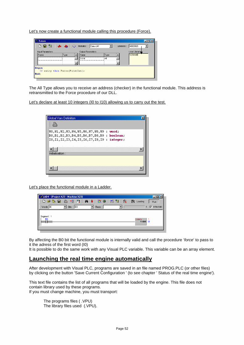
Let’s now create a functional module calling this procedure (Force).
The All Type allows you to receive an address (checker) in the functional module. This address is retransmitted to the Force procedure of our DLL. Let’s declare at least 10 integers (I0 to I10) allowing us to carry out the test.
Let’s place the functional module in a Ladder.
By affecting the B0 bit the functional module is internally valid and call the procedure ‘force’ to pass to it the adress of the first word (I0) It is possible to do the same work with any Visual PLC variable. This variable can be an array element.
Launching the real time engine automatically After development with Visual PLC, programs are saved in an file named PROG.PLC (or other files) by clicking on the button 'Save Current Configuration ' (to see chapter ' Status of the real time engine'). This text file contains the list of all programs that will be loaded by the engine. This file does not contain library used by these programs. If you must change machine, you must transport: The programs files ( .VPU) The library files used (.VPU).
Page 53
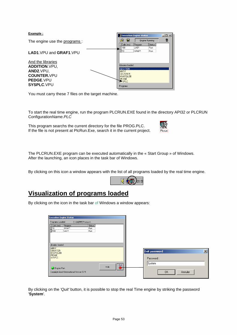
Example : The engine use the programs :
LAD1.VPU and GRAF1.VPU And the libraries ADDITION.VPU, AND2.VPU, COUNTER.VPU PEDGE.VPU SYSPLC.VPU You must carry these 7 files on the target machine. To start the real time engine, run the program PLCRUN.EXE found in the directory API32 or PLCRUN ConfigurationName.PLC This program searchs the current directory for the file PROG.PLC. If the file is not present at PlcRun.Exe, search it in the current project. The PLCRUN.EXE program can be executed automatically in the « Start Group » of Windows. After the launching, an icon places in the task bar of Windows. By clicking on this icon a window appears with the list of all programs loaded by the real time engine.
Visualization of programs loaded By clicking on the icon in the task bar of Windows a window appears: By clicking on the 'Quit' button, it is possible to stop the real Time engine by striking the password 'System'.
Page 54
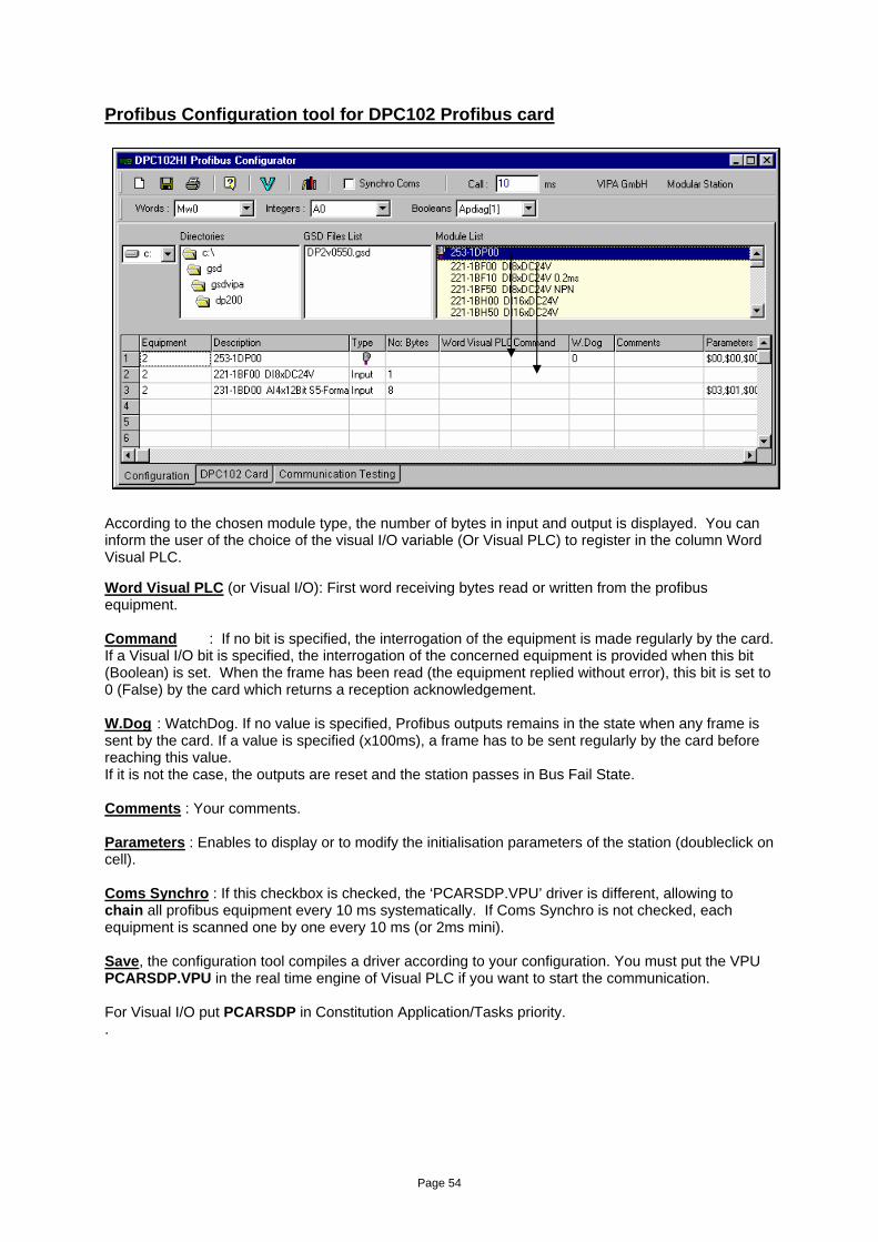
Profibus Configuration tool for DPC102 Profibus card According to the chosen module type, the number of bytes in input and output is displayed. You can inform the user of the choice of the visual I/O variable (Or Visual PLC) to register in the column Word Visual PLC. Word Visual PLC (or Visual I/O): First word receiving bytes read or written from the profibus equipment. Command : If no bit is specified, the interrogation of the equipment is made regularly by the card. If a Visual I/O bit is specified, the interrogation of the concerned equipment is provided when this bit (Boolean) is set. When the frame has been read (the equipment replied without error), this bit is set to 0 (False) by the card which returns a reception acknowledgement. W.Dog : WatchDog. If no value is specified, Profibus outputs remains in the state when any frame is sent by the card. If a value is specified (x100ms), a frame has to be sent regularly by the card before reaching this value. If it is not the case, the outputs are reset and the station passes in Bus Fail State. Comments : Your comments. Parameters : Enables to display or to modify the initialisation parameters of the station (doubleclick on cell). Coms Synchro : If this checkbox is checked, the ‘PCARSDP.VPU’ driver is different, allowing to chain all profibus equipment every 10 ms systematically. If Coms Synchro is not checked, each equipment is scanned one by one every 10 ms (or 2ms mini). Save, the configuration tool compiles a driver according to your configuration. You must put the VPU PCARSDP.VPU in the real time engine of Visual PLC if you want to start the communication. For Visual I/O put PCARSDP in Constitution Application/Tasks priority. .
Page 55
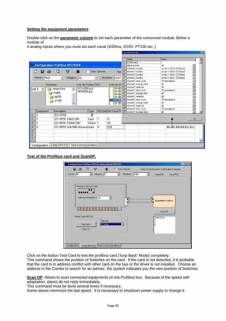
Setting the equipment parameters Double-click on the parameter column to set each parameter of the concerned module. Below a module of 4 analog inputs where you must set each canal (4/20ma, 0/10V, PT100 etc..) Test of the Profibus card and ScanDP.
Click on the button Test Card to test the profibus card (‘loop Back’ Mode) completely. This command shows the position of Switches on the card. If the card is not detected, it is probable that the card is in address conflict with other card on the bus or the driver is not installed. Choose an address in the Combo to search for an adress', the system indicates you the new position of Switches. Scan DP: Allows to scan connected equipments on the Profibus bus. Because of the speed self-adaptation, slaves do not reply immediately. This command must be done several times if necessary. Some slaves memorize the last speed. It is necessary to shutdown power supply to change it
Page 56
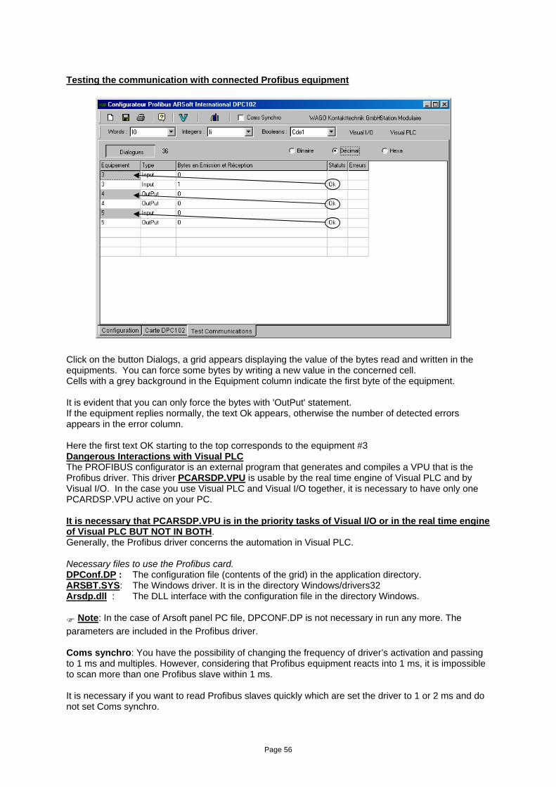
Testing the communication with connected Profibus equipment Click on the button Dialogs, a grid appears displaying the value of the bytes read and written in the equipments. You can force some bytes by writing a new value in the concerned cell. Cells with a grey background in the Equipment column indicate the first byte of the equipment. It is evident that you can only force the bytes with 'OutPut' statement. If the equipment replies normally, the text Ok appears, otherwise the number of detected errors appears in the error column. Here the first text OK starting to the top corresponds to the equipment #3 Dangerous Interactions with Visual PLC The PROFIBUS configurator is an external program that generates and compiles a VPU that is the Profibus driver. This driver PCARSDP.VPU is usable by the real time engine of Visual PLC and by Visual I/O. In the case you use Visual PLC and Visual I/O together, it is necessary to have only one PCARDSP.VPU active on your PC. It is necessary that PCARSDP.VPU is in the priority tasks of Visual I/O or in the real time engine of Visual PLC BUT NOT IN BOTH. Generally, the Profibus driver concerns the automation in Visual PLC. Necessary files to use the Profibus card. DPConf.DP : The configuration file (contents of the grid) in the application directory. ARSBT.SYS: The Windows driver. It is in the directory Windows/drivers32 Arsdp.dll : The DLL interface with the configuration file in the directory Windows.
Note: In the case of Arsoft panel PC file, DPCONF.DP is not necessary in run any more. The parameters are included in the Profibus driver. Coms synchro: You have the possibility of changing the frequency of driver’s activation and passing to 1 ms and multiples. However, considering that Profibus equipment reacts into 1 ms, it is impossible to scan more than one Profibus slave within 1 ms. It is necessary if you want to read Profibus slaves quickly which are set the driver to 1 or 2 ms and do not set Coms synchro.
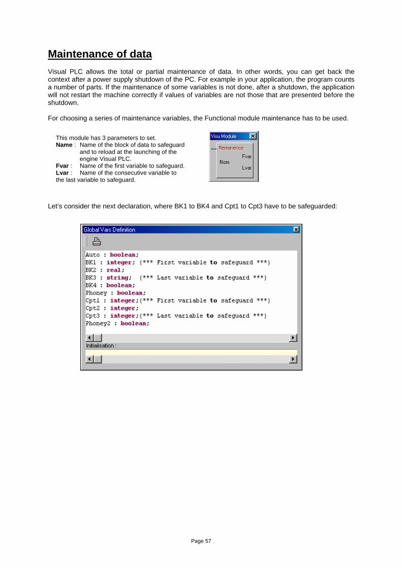
Page 57
Maintenance of data Visual PLC allows the total or partial maintenance of data. In other words, you can get back the context after a power supply shutdown of the PC. For example in your application, the program counts a number of parts. If the maintenance of some variables is not done, after a shutdown, the application will not restart the machine correctly if values of variables are not those that are presented before the shutdown. For choosing a series of maintenance variables, the Functional module maintenance has to be used.
Let’s consider the next declaration, where BK1 to BK4 and Cpt1 to Cpt3 have to be safeguarded:
This module has 3 parameters to set. Name : Name of the block of data to safeguard
and to reload at the launching of the engine Visual PLC.
Fvar : Name of the first variable to safeguard. Lvar : Name of the consecutive variable to the last variable to safeguard.
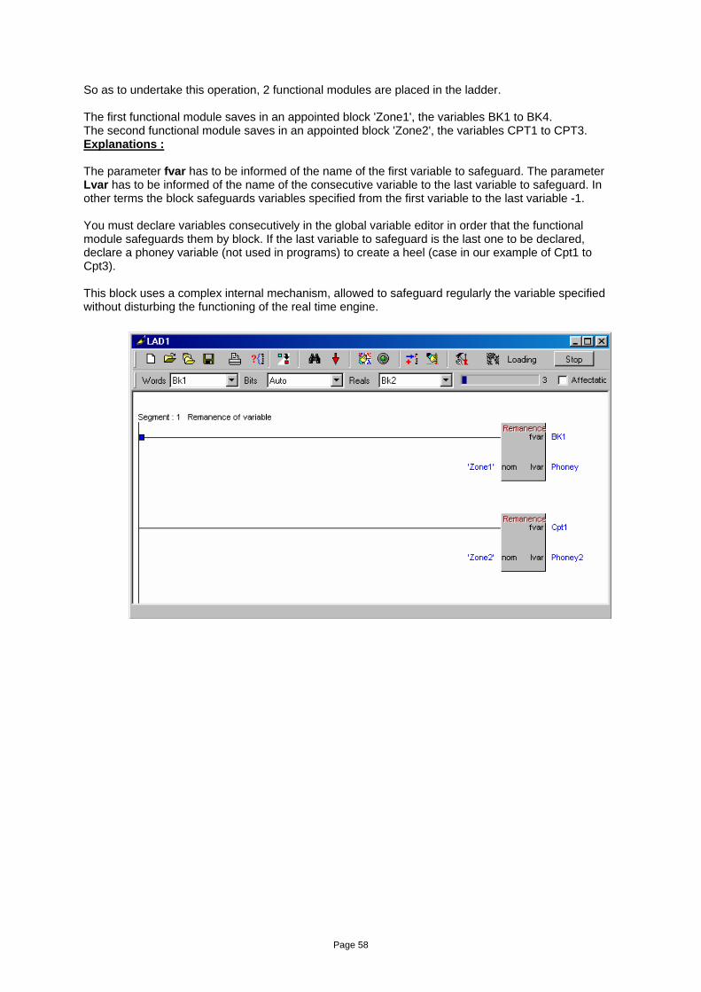
Page 58
So as to undertake this operation, 2 functional modules are placed in the ladder. The first functional module saves in an appointed block 'Zone1', the variables BK1 to BK4. The second functional module saves in an appointed block 'Zone2', the variables CPT1 to CPT3. Explanations : The parameter fvar has to be informed of the name of the first variable to safeguard. The parameter Lvar has to be informed of the name of the consecutive variable to the last variable to safeguard. In other terms the block safeguards variables specified from the first variable to the last variable -1. You must declare variables consecutively in the global variable editor in order that the functional module safeguards them by block. If the last variable to safeguard is the last one to be declared, declare a phoney variable (not used in programs) to create a heel (case in our example of Cpt1 to Cpt3). This block uses a complex internal mechanism, allowed to safeguard regularly the variable specified without disturbing the functioning of the real time engine.
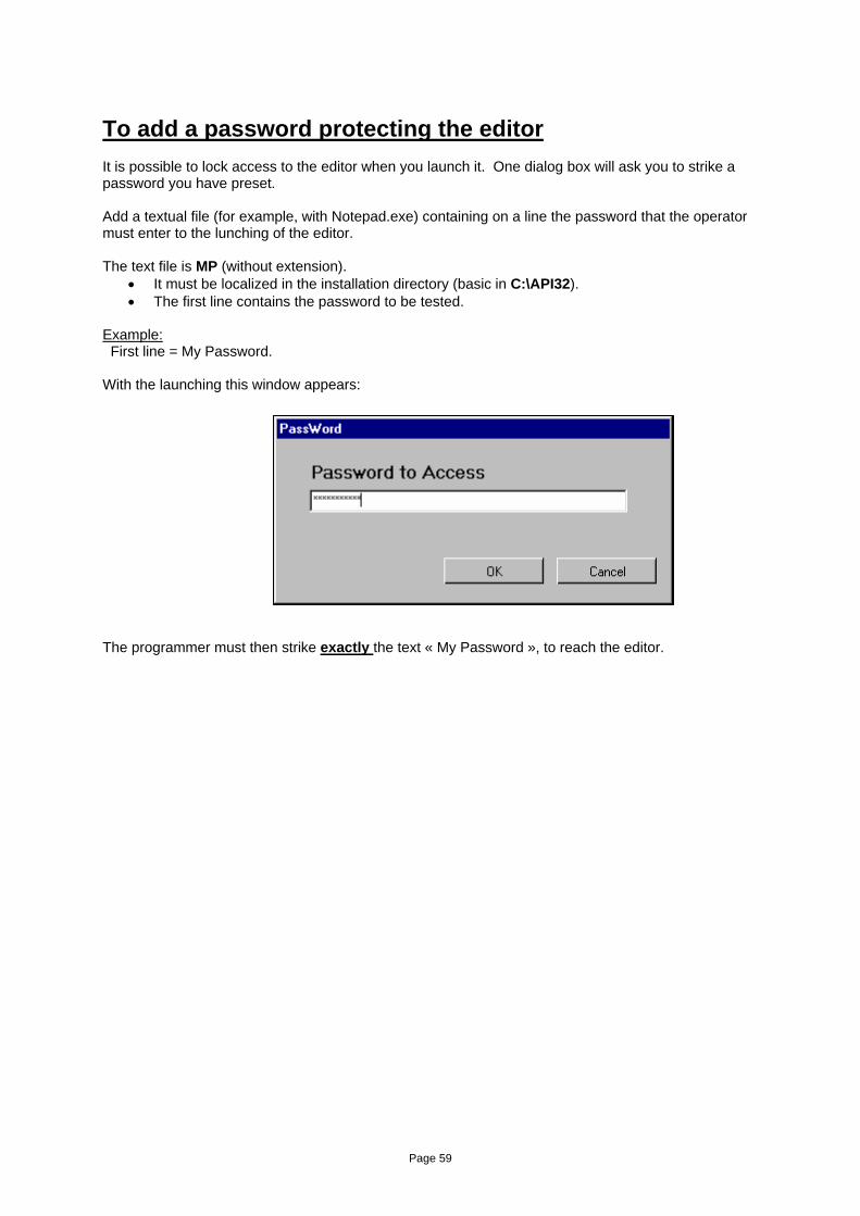
Page 59
To add a password protecting the editor It is possible to lock access to the editor when you launch it. One dialog box will ask you to strike a password you have preset. Add a textual file (for example, with Notepad.exe) containing on a line the password that the operator must enter to the lunching of the editor. The text file is MP (without extension).
• It must be localized in the installation directory (basic in C:\API32). • The first line contains the password to be tested.
Example: First line = My Password. With the launching this window appears:
The programmer must then strike exactly the text « My Password », to reach the editor.