Embed Size (px)
Citation preview
Kalpakjian • SchmidManufacturing Engineering and Technology © 2001 Prentice-Hall Page 7-1
CHAPTER 33
Surface Treatment, Coating, andCleaning
Kalpakjian • SchmidManufacturing Engineering and Technology © 2001 Prentice-Hall Page 7-2
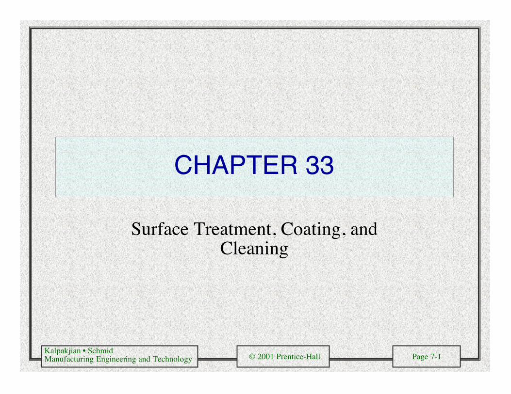
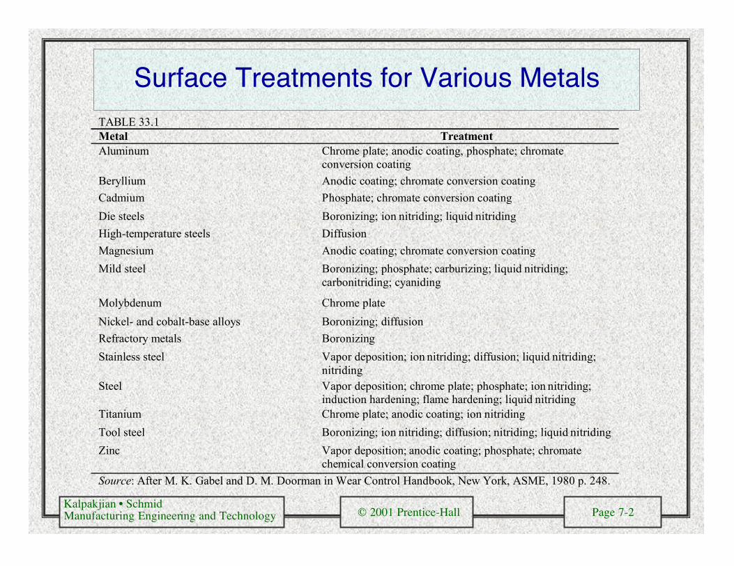
Surface Treatments for Various MetalsTABLE 33.1Metal TreatmentAluminum Chrome plate; anodic coating, phosphate; chromate
conversion coating
Beryllium Anodic coating; chromate conversion coating
Cadmium Phosphate; chromate conversion coating
Die steels Boronizing; ion nitriding; liquid nitriding
High-temperature steels Diffusion
Magnesium Anodic coating; chromate conversion coating
Mild steel Boronizing; phosphate; carburizing; liquid nitriding;carbonitriding; cyaniding
Molybdenum Chrome plate
Nickel- and cobalt-base alloys Boronizing; diffusion
Refractory metals Boronizing
Stainless steel Vapor deposition; ion nitriding; diffusion; liquid nitriding;nitriding
Steel Vapor deposition; chrome plate; phosphate; ion nitriding;induction hardening; flame hardening; liquid nitriding
Titanium Chrome plate; anodic coating; ion nitriding
Tool steel Boronizing; ion nitriding; diffusion; nitriding; liquid nitriding
Zinc Vapor deposition; anodic coating; phosphate; chromatechemical conversion coating
Source: After M. K. Gabel and D. M. Doorman in Wear Control Handbook, New York, ASME, 1980 p. 248.
Kalpakjian • SchmidManufacturing Engineering and Technology © 2001 Prentice-Hall Page 7-3
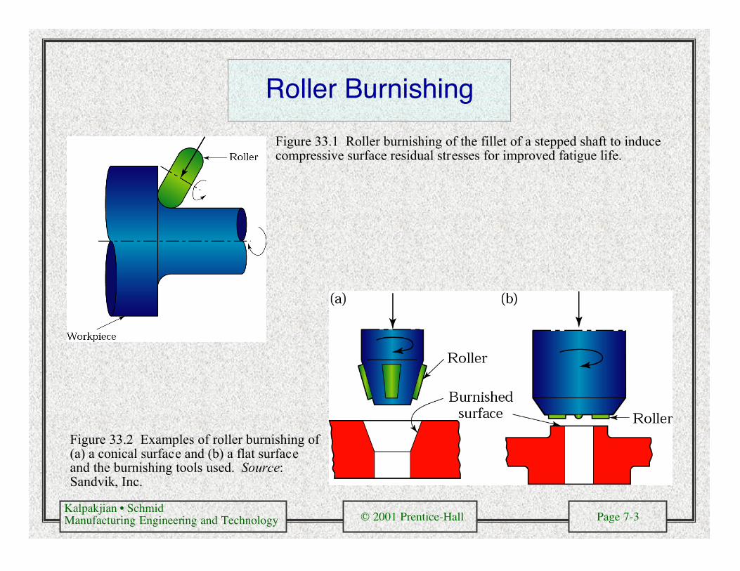
Roller Burnishing
Figure 33.1 Roller burnishing of the fillet of a stepped shaft to inducecompressive surface residual stresses for improved fatigue life.
Figure 33.2 Examples of roller burnishing of(a) a conical surface and (b) a flat surfaceand the burnishing tools used. Source:Sandvik, Inc.

Kalpakjian • SchmidManufacturing Engineering and Technology © 2001 Prentice-Hall Page 7-4
ThermalSpray
Operations
Figure 33.3Schematicillustrations ofthermal sprayoperations. (a)Thermal wirespray. (b)Thermal metal-powder spray. (c)Plasma spray.
Kalpakjian • SchmidManufacturing Engineering and Technology © 2001 Prentice-Hall Page 7-5
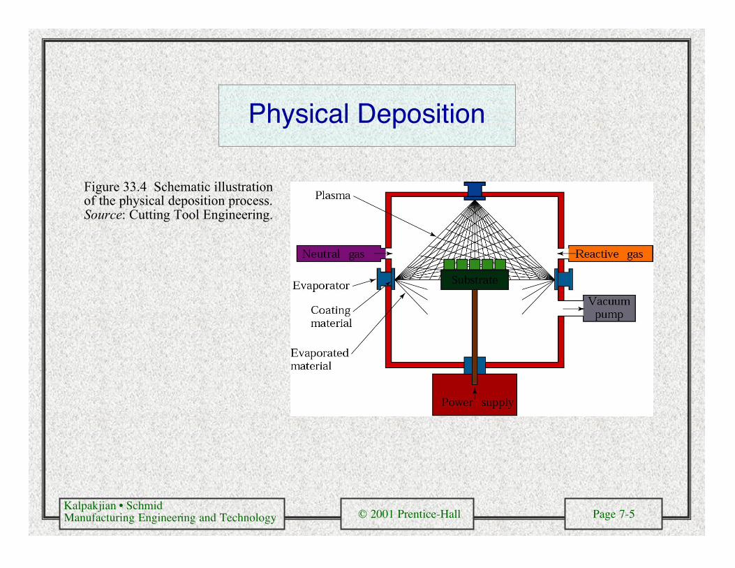
Physical Deposition
Figure 33.4 Schematic illustrationof the physical deposition process.Source: Cutting Tool Engineering.
Kalpakjian • SchmidManufacturing Engineering and Technology © 2001 Prentice-Hall Page 7-6
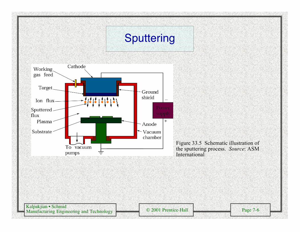
Sputtering
Figure 33.5 Schematic illustration ofthe sputtering process. Source: ASMInternational
Kalpakjian • SchmidManufacturing Engineering and Technology © 2001 Prentice-Hall Page 7-7
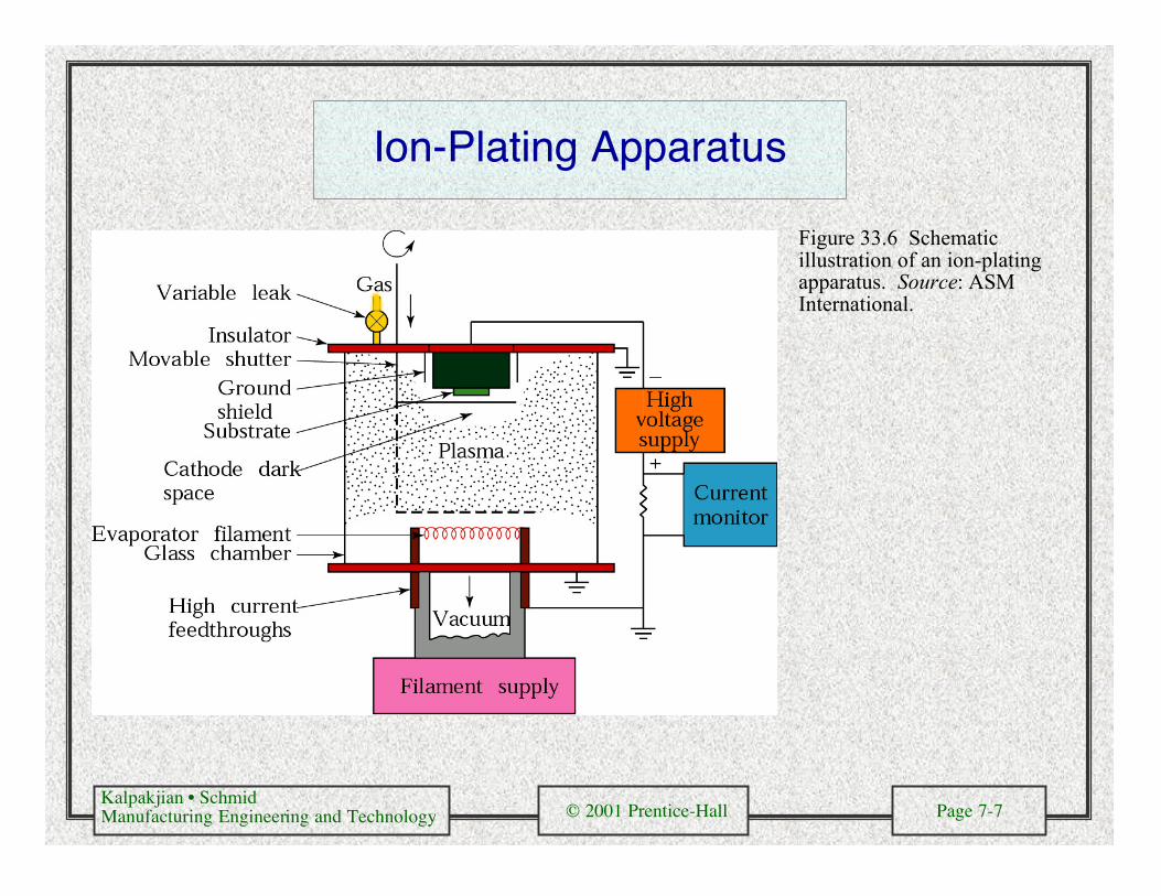
Ion-Plating Apparatus
Figure 33.6 Schematicillustration of an ion-platingapparatus. Source: ASMInternational.
Kalpakjian • SchmidManufacturing Engineering and Technology © 2001 Prentice-Hall Page 7-8
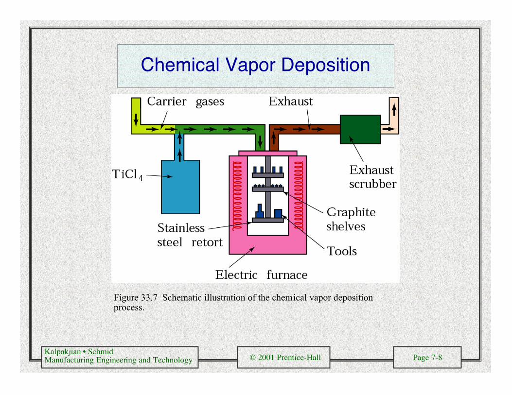
Chemical Vapor Deposition
Figure 33.7 Schematic illustration of the chemical vapor depositionprocess.
Kalpakjian • SchmidManufacturing Engineering and Technology © 2001 Prentice-Hall Page 7-9
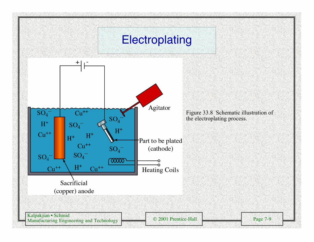
Electroplating
Figure 33.8 Schematic illustration ofthe electroplating process.
Kalpakjian • SchmidManufacturing Engineering and Technology © 2001 Prentice-Hall Page 7-10
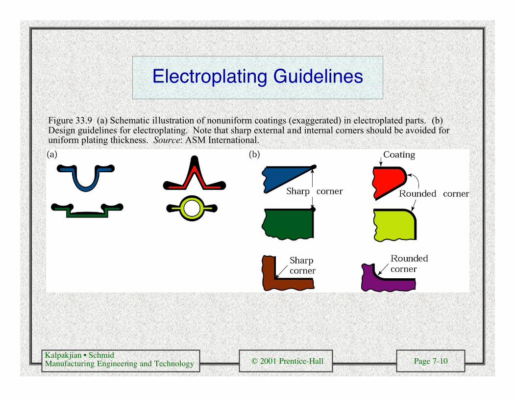
Electroplating Guidelines
Figure 33.9 (a) Schematic illustration of nonuniform coatings (exaggerated) in electroplated parts. (b)Design guidelines for electroplating. Note that sharp external and internal corners should be avoided foruniform plating thickness. Source: ASM International.
Kalpakjian • SchmidManufacturing Engineering and Technology © 2001 Prentice-Hall Page 7-11
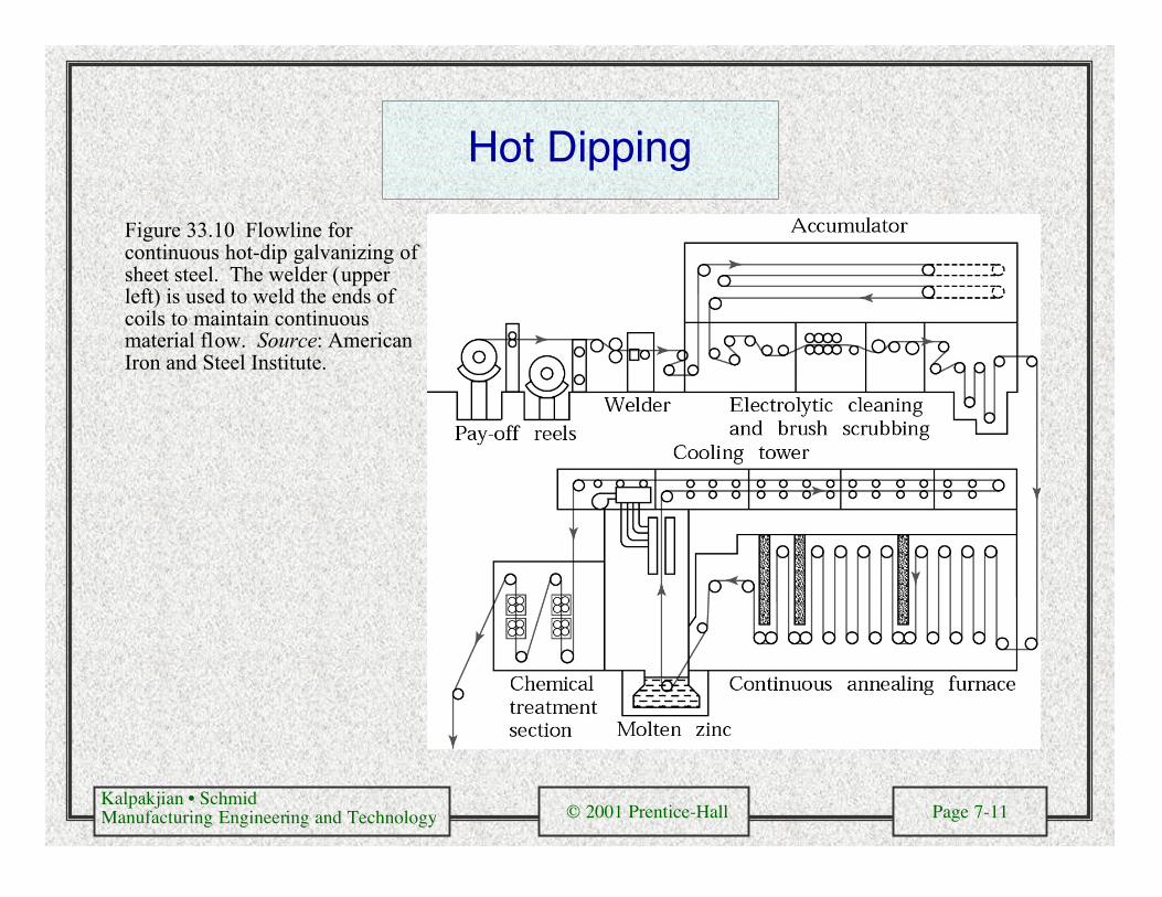
Hot Dipping
Figure 33.10 Flowline forcontinuous hot-dip galvanizing ofsheet steel. The welder (upperleft) is used to weld the ends ofcoils to maintain continuousmaterial flow. Source: AmericanIron and Steel Institute.
Kalpakjian • SchmidManufacturing Engineering and Technology © 2001 Prentice-Hall Page 7-12
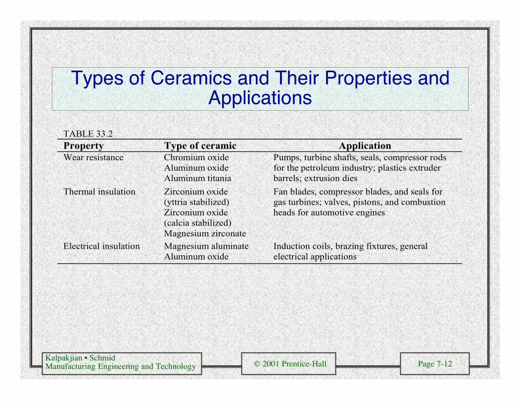
Types of Ceramics and Their Properties andApplications
TABLE 33.2Property Type of ceramic ApplicationWear resistance Chromium oxide
Aluminum oxideAluminum titania
Pumps, turbine shafts, seals, compressor rodsfor the petroleum industry; plastics extruderbarrels; extrusion dies
Thermal insulation Zirconium oxide(yttria stabilized)Zirconium oxide(calcia stabilized)Magnesium zirconate
Fan blades, compressor blades, and seals forgas turbines; valves, pistons, and combustionheads for automotive engines
Electrical insulation Magnesium aluminateAluminum oxide
Induction coils, brazing fixtures, generalelectrical applications
Kalpakjian • SchmidManufacturing Engineering and Technology © 2001 Prentice-Hall Page 7-13
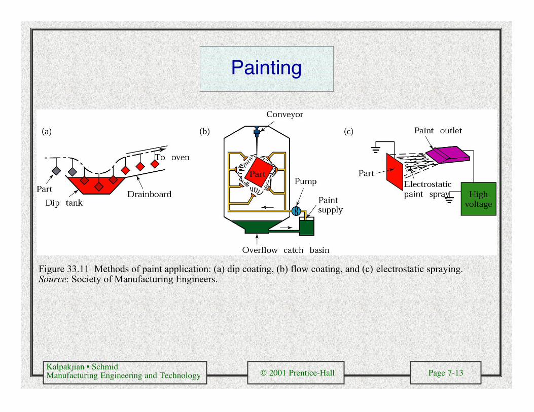
Painting
Figure 33.11 Methods of paint application: (a) dip coating, (b) flow coating, and (c) electrostatic spraying.Source: Society of Manufacturing Engineers.