Embed Size (px)
Citation preview

This article was downloaded by: [Aston University]On: 30 January 2014, At: 00:55Publisher: Taylor & FrancisInforma Ltd Registered in England and Wales Registered Number: 1072954 Registeredoffice: Mortimer House, 37-41 Mortimer Street, London W1T 3JH, UK
Fullerenes, Nanotubes and CarbonNanostructuresPublication details, including instructions for authors andsubscription information:http://www.tandfonline.com/loi/lfnn20
Production of Carbon Nanotubesover Fe-FSM-16 Catalytic Material:Effect of Acetylene Flow Rate and CVDTemperatureSinem Taş a , Firuze Okyay a , Meltem Sezen b , Harald Plank c &
Yuda Yürüm aa Faculty of Engineering and Natural Sciences , Sabanci University ,Orhanli, Tuzla, Istanbul , Turkeyb Nanotechnology Research and Application Center , SabanciUniversity , Orhanli, Tuzla, Istanbul , Turkeyc Institute for Electron Microscopy and Fine Structure Research, GrazUniversity of Technology , Graz , AustriaPublished online: 15 Oct 2012.
To cite this article: Sinem Taş , Firuze Okyay , Meltem Sezen , Harald Plank & Yuda Yürüm (2013)Production of Carbon Nanotubes over Fe-FSM-16 Catalytic Material: Effect of Acetylene Flow Rate andCVD Temperature, Fullerenes, Nanotubes and Carbon Nanostructures, 21:4, 311-325
To link to this article: http://dx.doi.org/10.1080/1536383X.2011.613541
PLEASE SCROLL DOWN FOR ARTICLE
Taylor & Francis makes every effort to ensure the accuracy of all the information (the“Content”) contained in the publications on our platform. However, Taylor & Francis,our agents, and our licensors make no representations or warranties whatsoever as tothe accuracy, completeness, or suitability for any purpose of the Content. Any opinionsand views expressed in this publication are the opinions and views of the authors,and are not the views of or endorsed by Taylor & Francis. The accuracy of the Contentshould not be relied upon and should be independently verified with primary sourcesof information. Taylor and Francis shall not be liable for any losses, actions, claims,proceedings, demands, costs, expenses, damages, and other liabilities whatsoever orhowsoever caused arising directly or indirectly in connection with, in relation to or arisingout of the use of the Content.
This article may be used for research, teaching, and private study purposes. Anysubstantial or systematic reproduction, redistribution, reselling, loan, sub-licensing,

systematic supply, or distribution in any form to anyone is expressly forbidden. Terms &Conditions of access and use can be found at http://www.tandfonline.com/page/terms-and-conditions
Dow
nloa
ded
by [
Ast
on U
nive
rsity
] at
00:
55 3
0 Ja
nuar
y 20
14

Fullerenes, Nanotubes, and Carbon Nanostructures, 21: 311–325, 2013Copyright © Taylor & Francis Group, LLCISSN: 1536-383X print / 1536-4046 onlineDOI: 10.1080/1536383X.2011.613541
Production of Carbon Nanotubes overFe-FSM-16 Catalytic Material: Effect of Acetylene
Flow Rate and CVD Temperature
SINEM TAS1, FIRUZE OKYAY1, MELTEM SEZEN2, HARALDPLANK3 AND YUDA YÜRÜM1
1Faculty of Engineering and Natural Sciences, Sabanci University, Orhanli, Tuzla,Istanbul, Turkey2Nanotechnology Research and Application Center, Sabanci University, Orhanli,Tuzla, Istanbul, Turkey3Institute for Electron Microscopy and Fine Structure Research, Graz Universityof Technology, Graz, Austria
In this article, a high-yield synthesis of high-quality carbon nanotubes (CNTs) using Fecatalysts trapped within channels of Folded Sheet Mesoporous Materials, FSM-16, bychemical vapor deposition (CVD), using acetylene as a hydrocarbon source, is reported.The effect of reaction temperature and acetylene flow rate on the formation of CNTswas investigated. It was found that the yield, diameter and quality of CNTs synthe-sized strongly depend on reaction temperature during CVD. The resulting materialswere characterized by scanning electron microscopy, Raman spectroscopy and thermo-gravimetric analysis. Our research found that carbon deposition, diameter and qualityof the CNTs strongly depend on CVD temperature. However, the acetylene flow ratedid not have any significant effect on diameter distribution. Raman measurement indi-cated that the synthesized products were multi-walled carbon nanotubes (MWCNTs).High-resolution transmission electron micrographs of samples reveal the multi-layersidewalls of individual MWCNTs with a diameter of 40 nm, in which hollow and tubalstructures were observed.
Keywords Carbon nanotubes, chemical vapor deposition, FSM-16, Fe catalyst,acetylene
Introduction
The discovery of carbon nanotubes (CNTs) is an important stepping stone for the nanotech-nological progress. Due to the strong knowledge of the electrical and mechanical propertiesof CNTs, they propose many application fields, including polymer reinforcements for com-posites, energy storage and electronics (1). Unfortunately, the cost-effective production ofCNTs is an issue. Generally, CNTs are synthesized by three different production methods:discharge, laser ablation and chemical vapor deposition (CVD). Both arc discharge andlaser ablation methods are very difficult to scale up. On the other hand, due to its simplicity,low cost, product purity and easily controlled growth factors, CVD is the most promisingmethod for industrial scale production of CNTs (2).
Address correspondence to Yuda Yürüm, Faculty of Engineering and Natural Sciences, SabanciUniversity, Orhanli, Tuzla, Istanbul 34956, Turkey. E-mail: [email protected]
311
Dow
nloa
ded
by [
Ast
on U
nive
rsity
] at
00:
55 3
0 Ja
nuar
y 20
14

312 S. Tas et al.
Basically, the CVD process is dissociation of hydrocarbon molecules on the metalcatalyst at high temperatures (500–1000◦C) for a certain period of time. Precipitationof the carbon on the metal particles leads to formation of CNTs. Temperature, hydro-carbon concentration, metal particle size, pretreatment of metallic catalyst and synthesistime are the crucial parameters that affect the quality of the final product. Dependingon these parameters, single-walled carbon nanotubes (SWCNTs) and multi-walled carbonnanotubes (MWCNTs) can be produced (3).
Since the CVD process depends on the catalytic decomposition of hydrocarbonmolecules, the role of the catalyst is important for CNT formation. Metal particle size iscrucial for control of CNT diameter. Supported catalysts ensure the control of particle sizefor the growth process. Ordered mesoporous molecular sieves are preferred as a supportmaterial because of high specific surface area, large pore volume, uniform pore structureand tunable pore size varying from 2 to 10 nm (4). Among mesoporous materials, FSM-16 is a good candidate because of its large and hexagonal pore structure with high specificsurface area. Indeed, the ordered structure of FSM-16 ensures the good dispersion of metalparticles. When FSM-16 is loaded with metal particles, it can be used as a catalyst forvarious applications such as CNT production, hydrogen storage and adsorption.
To meet the demand for the CVD process, the type of metal loaded on the supportmaterial is critical. In earlier studies, researchers reported that Fe, Ni and Co are frequentlyused transition metals as catalysts for CNT production (5). In addition to these, Sc, Ti, V,Cr, Mn and Zn and a combination of them are also used as catalysts (6,7). Also, 3d metalshave been attractive by means of obtaining nanotubes with better performance. Fe, Ni andCo and their combinations as catalysts offer attractive routes for the synthesis of nanotubesdue to the interactions of their partially filled 3d orbitals with the valence orbitals of thecarbon precursors (5).
There are many studies focused on Fe-loaded catalysts. Various researchers applied dif-ferent templates for Fe-based catalysis. It is reported that the interaction between metal par-ticles and the template affects the catalytic activity. Kukovecz et al. (8) obtained MWCNTswith Fe supported on mixtures of Al2O3-SiO2. Many researchers found that Fe loaded SiO2
is a promising catalyst for MWCNTs synthesis (9–13). Much previous work was orientedtowards synthesis of MWCNTs on Fe-supported silicon substrate (11–14). Zhao et al. (4)and Atchudan et al. (15) studied MWCNTs synthesis on Fe-MCM-41. However, so faronly Kobayashi et al. reported SWCNTs production over Fe(CH3COO)2/Co(CH3COO)2.4H2O and Co(NO3)2·6H2O impregnated FSM-16 (16). Although the uniformed mesoporescould make the catalysts well dispersed in the Fe-FSM-16 molecular sieve, the Fe-FSM-16 catalysts had not been used efficiently to prepare carbon nanotubes with the CVDmethod.
In the present study, we report the catalytic activity of Fe impregnated FSM-16 inthe production of carbon nanotubes by the CVD method using acetylene as a hydrocarbonsource. The effects of different reaction temperatures and acetylene flow rate on the for-mation of CNTs were investigated. The morphology and crystallinity of CNTs grown onFe-FSM-16 catalyst were investigated using scanning electron microscopy (SEM), Ramanspectroscopy and thermogravimetric analysis (TGA).
Experimental
Synthesis of Fe-FSM-16
According to the previously published procedure (17), synthesis of FSM-16 was carriedout by using kanemite NaHSi2O5·3H2O and hexadecyltrimethylammonium bromide.
Dow
nloa
ded
by [
Ast
on U
nive
rsity
] at
00:
55 3
0 Ja
nuar
y 20
14

Production of Carbon Nanotubes 313
The impregnation method was described as follows. First, the dried powder of as-synthesized FSM-16 was mixed with iron (III) nitrate nonahydrate (Fe(NO3)3·9H2O)solutions with 4wt% metal loadings. The resultant mixture was stirred at room tempera-ture for 1 hour, and then the excess water was removed by stirring at 70◦C. The sample wasfiltered, washed and dried at 80◦C. Finally, the Fe impregnated sample was calcinated at550◦C for 4 hours in order to remove surfactant.
Synthesis of Carbon Nanotubes
Carbon nanotube production was performed using a CVD system. 100 mg of the synthe-sized catalyst was placed into a boat crucible and put in the middle of the quartz tube(∼900 mm in length, 30 mm diameter) of the CVD system to ensure isothermal condi-tions. The furnace was heated up to 300◦C under 1000 mL/min Ar flow for 30 minutesto stabilize the catalyst and to purge oxygen present in the furnace prior to the start ofthe flow of acetylene. Afterwards, the system was set to a temperature between 500◦Cand 800◦C for CNT growth. When the temperature set for the experiment was attained,acetylene (40 mL/min) diluted in Ar (1200 mL/min) was introduced into the system. Theflow of the acetylene was continued for 30 minutes in all experiments. The samples werecooled to room temperature under an Ar atmosphere (1000 mL/min).
To investigate the effect of the flow rate of acetylene the reaction temperature wasset to 700◦C (as described below the optimum temperature for CNT production), and theacetylene flow rate was changed in the range of 40–120 mL/min.
Carbon nanotube yield was calculated as
Carbon Yield = mTotal C+Catalyst − mCatalyst
Flow rate of C2H2
(l/
min) × Time (min)
22.4 l/mol of C2H2× 26g/mol of C2H2 × 24g of C
26g of C2H2
where mTotal C+Catalyst is the weight of carbon product and catalyst, and mCatalyst is the weightof catalyst used for CNTs growth.
Carbon deposition in an experiment = mTotal C+Catalyst − mCatalyst
Characterization Methods
The synthesized metal-impregnated FSM-16 was characterized by XRD, surface analysistechniques using N2 adsorption–desorption isotherms. X-ray diffraction (XRD) patternswere recorded with a Bruker AXS advance powder diffractometer equipped with aSiemens X-ray gun and Bruker AXS Diffrac PLUS software, using Cu Ka radiation(k = 1.5418 Angstrom). The samples were scanned in the 2θ range of 2–10◦, with stepsize of 0.010. Specific surface areas, pore diameters and pore volumes were determined byQuantachrome NOVA 2200 series Surface Analyzer. The nitrogen adsorption/desorptionisotherms were recorded at 77 K. Prior to physisorption measurements, the samples wereoutgassed at 423K for 4 hours. The specific surface area and pore volume of the pure andFe loaded FSM-16 materials were calculated using the BET and BJH methods.
Different characterization techniques were carried out to examine CNT growth on thecatalyst particles. The diameter and uniformity of carbon nanotubes were examined withLeo G34-Supra 35VP SEM. The transmission electron microscopy (TEM) micrographswere acquired by an FEI Tecnai F20 instrument at 200 keV. TGA and Raman spectroscopywere also used to recognize the quality of CNTs as well as amount of defects. Raman
Dow
nloa
ded
by [
Ast
on U
nive
rsity
] at
00:
55 3
0 Ja
nuar
y 20
14

314 S. Tas et al.
spectra of CNT samples were recorded on a Renishaw InVia Reflex Raman MicroscopySystem (Renishaw Plc.; New Mills, Wotton-under-Edge Gloucestershire, UK) with a514 nm argon ion laser in the range of 100–3200 cm−1. TGA measurements were per-formed on a Netzsch STA 449 C Jupiter differential thermogravimetric analyzer (precisionof temperature measurement ±2◦C, microbalance sensitivity <5 μg) under air atmospherewith a flow rate 50 ml/min, at a linear heating rate of 5◦C/min.
Results and Discussion
X-ray diffraction pattern of Fe-FSM-16
Figure 1 shows the XRD patterns of FSM-16 and Fe-FSM-16. The peaks were observed inthe lower angle region (2θ < 10◦), indicating the hexagonal arrays of planes (18). Althoughboth FSM-16 and Fe-FSM-16 have almost the same XRD pattern, the intensity of theobserved peaks decreased in the case of Fe-FSM-16. This showed that the ordered structurewas partially lost after metal impregnation.
Nitrogen adsorption–desorption isotherms
Physical adsorption is one of the methods for the porous materials characterization and pro-vides information about surface area, pore size, and pore size distribution. Specific surfacearea, pore diameter and pore volume data of the FSM-16 and Fe-FSM-16 are presentedin Table 1. Specific surface area of the FSM-16 and Fe-FSM-16 were 755.1 m2/g and581.5 m2/g, respectively. It seemed that the impregnation of Fe(NO3)3·9H2O on the FSM-16 decreased the surface area due to intrapore formation of ferric oxide. This reduction inthe surface area in the case of Fe-FSM-16 was also supported by the lower values of porediameters (from 3.6 nm to 2.5 nm) and pore volumes (from 1.43 cc/g to 0.55 cc/g). In com-bination with the XRD data, surface area measurements offered detailed information aboutpore architecture of the catalytic material. This is important for the accessibility of activesites and is related to the catalytic activity of the Fe-FSM-16.
The N2 adsorption–desorption isotherms of FSM-16 and Fe-FSM-16 samples areshown in Figure 2. Samples showed a well-defined step at P/P0 ≈ 0.3–0.5, whichrepresented capillary condensation of N2 gas and uniformity of the pores (19).
2 3 4 5 6 7 8
Inte
nsity
(a.
u)
4 wt % Fe-FSM-16
FSM-16(200)(110)
(100)
2θ
Figure 1. XRD pattern of FSM-16 and Fe impregnated FSM-16.
Dow
nloa
ded
by [
Ast
on U
nive
rsity
] at
00:
55 3
0 Ja
nuar
y 20
14

Production of Carbon Nanotubes 315
Table 1Results of specific surface area, pore size and pore volume of catalysts
SampleSpecific Surface Area
(m2/g)Average Pore
Diameter (nm)Total Pore Volume
(cc/g)
FSM-16 755.1 3.6 1.434wt% Fe-FSM-16 581.5 2.5 0.55
0.0 0.2 0.4 0.6 0.8 1.00
200
400
600
800
b
a
Vol
ume
(cc/
g)
Relative Pressure (P0/P)
Figure 2. Adsorption-desorption isotherms for (a) FSM-16 and (b) 4wt% Fe-FSM-16.
Effect of temperature on CNT growth
Temperature is an important parameter for the growth process, since the ability of a catalystto dissociate hydrocarbon depends on the reaction temperature. Indeed, raising the reactiontemperature increased the carbon formation over the catalysts (12). In order to investigatethe temperature effect, experiments were performed between 500◦C and 800◦C. Figure 3represents the carbon deposition and the carbon yield with respect to the reaction tempera-ture. While carbon yield was 2.88% at 600◦C, it increased to 8% at 800◦C. It was clear thatcarbon yield increased with increasing temperature.
Under pyrolytic thermal conditions hydrocarbon molecules broke, forming radicallicfragments; these attached to the catalyst particles and diffused through the catalyst particlesand then led to saturation level. During this process, rate determining step is diffusion ofcarbon from gas/metal interface to metal/carbon interface. As a result, mass flux originatedfrom the solubility difference of carbon at gas/metal interface and metal/carbon interface.At low temperatures, carbon solubility in solid solutions was very low (20). Therefore,CNTs’ structure was not observed at 500◦C. Beyond this temperature it seemed that higheramounts of carbon material started to deposit on the catalyst.
Figure 4 illustrates the SEM micrographs of CNTs growth over Fe-FSM-16 at 600◦C,700◦C and 800◦C. From the SEM images, it was clear that the growth mechanism of thecarbon nanotubes was tip growth. It was obviously observed from the results that the metalparticles were present at the top of the nanotube. Due to weak interaction between themetal particles and the support material, diffused carbon lifted metal particles to top of thenanotube.
Dow
nloa
ded
by [
Ast
on U
nive
rsity
] at
00:
55 3
0 Ja
nuar
y 20
14

316 S. Tas et al.
500 550 600 650 700 750 8000
20
40
60
80
100
Temperature /°C
Car
bon
Dep
osit
ion
/ (m
g)
500 550 600 650 700 750 800
0
2
4
6
8
Car
bon
Con
vers
ion
/ (%
)
a
b
Figure 3. a) Carbon deposition and b) Carbon conversion change as a function of reactiontemperature.
Figure 4. CNT growth over 4wt% FSM-16 at (a) 600◦C, (b) 700◦C, and (c) 800◦C.
Temperature had a predominant effect on CNT growth. Raising the temperature inaddition to the increase of the deposited amount of CNTs also affected the morphology ofthe carbon nanotubes. The effect of increasing the CVD temperature was observed as anincrease in the diameter of CNTs. Diameters of the CNTs produced at 800◦C was largerrelative to those produced at lower temperatures. Probably at higher temperatures, catalyticiron species merged on the FSM-16 surface, forming larger catalyst particles that causedwider diameter CNT formation by tip growth (21). Moreover, Zhao et al. (4) suggestedthe possibility of acetylene pyrolysis on the CNTs’ sidewalls, leading to tube diameterthickening.
Dow
nloa
ded
by [
Ast
on U
nive
rsity
] at
00:
55 3
0 Ja
nuar
y 20
14
Production of Carbon Nanotubes 317
Raising the temperature increased the carbon solubility due to enhanced diffusion,and this caused the formation of iron carbide at temperatures around 500◦C. For the CNTgrowth it is essential that iron carbide decompose and form α-Fe phase. This phase startsto form between 500◦C and 725◦C and stabilizes at temperatures above 725◦C (12). Afterthe formation of α-Fe phase, which is the active form for graphite precipitation, the rate ofCNT production increases rapidly. This explained why CNTs did not form at temperaturesaround 500◦C.
Although temperature increments led to high CNT yield, enhanced diffusion of car-bon and carbon solubility contributed to an increase of average diameter of CNTs. Forappropriate yield, the reaction temperature was 700◦C.
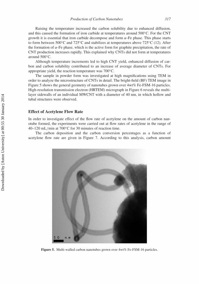
The sample in powder form was investigated at high magnifications using TEM inorder to analyze the microstructure of CNTs in detail. The bright-field (BF) TEM image inFigure 5 shows the general geometry of nanotubes grown over 4wt% Fe-FSM-16 particles.High-resolution transmission electron (HRTEM) micrograph in Figure 6 reveals the multi-layer sidewalls of an individual MWCNT with a diameter of 40 nm, in which hollow andtubal structures were observed.
Effect of Acetylene Flow Rate
In order to investigate effect of the flow rate of acetylene on the amount of carbon nan-otube formed, the experiments were carried out at flow rates of acetylene in the range of40–120 mL/min at 700◦C for 30 minutes of reaction time.
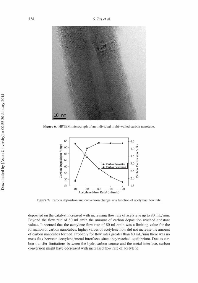
The carbon deposition and the carbon conversion percentages as a function ofacetylene flow rate are given in Figure 7. According to this analysis, carbon amount
Figure 5. Multi-walled carbon nanotubes grown over 4wt% Fe-FSM-16 particles.
Dow
nloa
ded
by [
Ast
on U
nive
rsity
] at
00:
55 3
0 Ja
nuar
y 20
14
318 S. Tas et al.
Figure 6. HRTEM micrograph of an individual multi-walled carbon nanotube.
40 60 80 100 12054
56
58
60
62
64
66
68
Carbon DepositionCarbon Conversion
Acetylene Flow Rate/ (ml/min)
1.5
2.0
2.5
3.0
3.5
4.0
4.5
Car
bon
Dep
osit
ion
/ (m
g)
Car
bon
Con
vers
ion
/ (%
)
Figure 7. Carbon deposition and conversion change as a function of acetylene flow rate.
deposited on the catalyst increased with increasing flow rate of acetylene up to 80 mL/min.Beyond the flow rate of 80 mL/min the amount of carbon deposition reached constantvalues. It seemed that the acetylene flow rate of 80 mL/min was a limiting value for theformation of carbon nanotubes; higher values of acetylene flow did not increase the amountof carbon nanotubes formed. Probably for flow rates greater than 80 mL/min there was nomass flux between acetylene/metal interfaces since they reached equilibrium. Due to car-bon transfer limitations between the hydrocarbon source and the metal interface, carbonconversion might have decreased with increased flow rate of acetylene.
Dow
nloa
ded
by [
Ast
on U
nive
rsity
] at
00:
55 3
0 Ja
nuar
y 20
14

Production of Carbon Nanotubes 319
Figure 8. CNTs growth over 4wt% Fe-FSM-16 with a) 80 ml/min acetylene flow rate, b) 120 ml/minacetylene flow rate.
Acetylene flow rate did not have any significant effect on the morphology of the result-ing CNTs. The resulting CNTs are shown in Figure 8. It was observed that the diameters ofthe CNTs were almost the same, in the range of 20–35 nm.
Raman Spectroscopy
Raman spectroscopy is a powerful tool for the characterization of the synthesized CNTswith respect to their diameter and quality (22). It is possible to distinguish SWCNTs
Dow
nloa
ded
by [
Ast
on U
nive
rsity
] at
00:
55 3
0 Ja
nuar
y 20
14

320 S. Tas et al.
and MWCNTs from each other with the aid of the Raman spectroscopical data. Radialbreathing mode (RBM) features appear over the lower wavenumber region. RBM modescorresponds coherent vibration of C atoms in radial direction. Raman bands appearingbetween 120 and 350 cm−1 are related to the SWCNTs for diameters in the range of0.7–2 nm (22,23). The Raman bands at higher wavenumber regions are characteristic ofboth SWCNTs and MWCNTs. The band in the range of 1500–1605 cm−1 is referred toas the G band (Graphite Band). G band correspond to vibration of C-C bond of graphenesheet. D band (Disorder Band) is usually observed in the range of 1250–1450 cm−1. D bandis the result of disordered-induced vibration of C-C bond. D/G peak intensity ratio is anindex for determining the CNTs structure (22).
The effects of CVD temperature on the structure of CNTs over 4wt% Fe-FSM-16 weredemonstrated in the Raman spectrum demonstrated in Figure 9. The presence of D and Gbands indicated the formation of graphitic carbon. Since there was not any peak observedin the RBM region, probably the CNTs produced were MWCNTs. While the G band wasseen at 1589 cm−1 of the carbon nanotubes produced at 600◦C, this band appeared at1592 cm−1 in the spectra of the products obtained at 700◦C and 800◦C. The D band posi-tion changed from 1341 cm−1 (600◦C and 700◦C) to 1350 cm−1 (800◦C). Moreover, as theCVD temperature increased, intensities of both D and G band decreased.
The comparison of the intensity ratios of these two peaks are given in Table 2. It wasobserved that increasing temperature resulted decrease in the intensity of D and G bands.
GD
600°C
700°C
800°C
Raman Shift / (cm–1)
Inte
nsity
/ (a
.u)
Inte
nsity
/ (a
.u)
0 500 1000 1500 2000 2500 3000
Raman Shift / (cm–1)0 500 1000 1500 2000 2500 3000
GD
40 cc/min80 cc/min100 cc/min120 cc/min
a
b
Figure 9. Raman spectra of carbon deposits on 4wt% Fe-FSM-16, a) Effect of reaction temperature,b) Effect of acetylene flow rate.
Dow
nloa
ded
by [
Ast
on U
nive
rsity
] at
00:
55 3
0 Ja
nuar
y 20
14
Production of Carbon Nanotubes 321
Table 2Parameters of D and G band for carbon deposits on 4wt% Fe-FSM-16 at different
temperature
Temperature
Raman Shift(cm−1)
(D-Band)
Raman Shift(cm−1)
(G-Band)
AbsoluteIntensity(D-Band)
AbsoluteIntensity(G-Band) ID/IG
600◦C 1341 1589 7981 9824 0.81700◦C 1341 1592 2426 2880 0.84800◦C 1350 1592 1378 1589 0.87
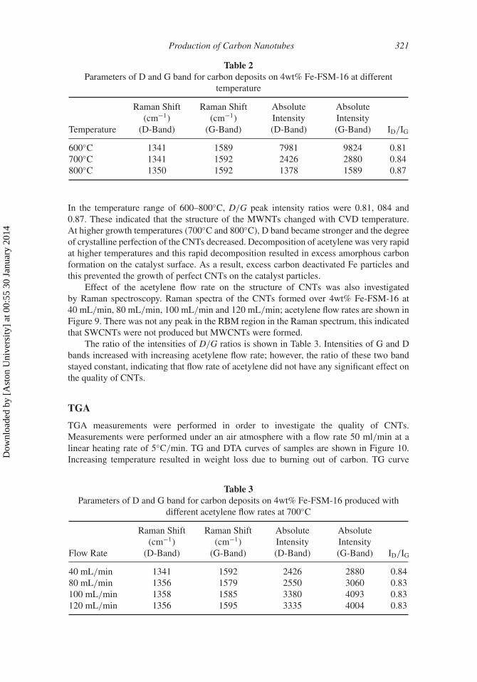
In the temperature range of 600–800◦C, D/G peak intensity ratios were 0.81, 084 and0.87. These indicated that the structure of the MWNTs changed with CVD temperature.At higher growth temperatures (700◦C and 800◦C), D band became stronger and the degreeof crystalline perfection of the CNTs decreased. Decomposition of acetylene was very rapidat higher temperatures and this rapid decomposition resulted in excess amorphous carbonformation on the catalyst surface. As a result, excess carbon deactivated Fe particles andthis prevented the growth of perfect CNTs on the catalyst particles.
Effect of the acetylene flow rate on the structure of CNTs was also investigatedby Raman spectroscopy. Raman spectra of the CNTs formed over 4wt% Fe-FSM-16 at40 mL/min, 80 mL/min, 100 mL/min and 120 mL/min; acetylene flow rates are shown inFigure 9. There was not any peak in the RBM region in the Raman spectrum, this indicatedthat SWCNTs were not produced but MWCNTs were formed.
The ratio of the intensities of D/G ratios is shown in Table 3. Intensities of G and Dbands increased with increasing acetylene flow rate; however, the ratio of these two bandstayed constant, indicating that flow rate of acetylene did not have any significant effect onthe quality of CNTs.
TGA
TGA measurements were performed in order to investigate the quality of CNTs.Measurements were performed under an air atmosphere with a flow rate 50 ml/min at alinear heating rate of 5◦C/min. TG and DTA curves of samples are shown in Figure 10.Increasing temperature resulted in weight loss due to burning out of carbon. TG curve
Table 3Parameters of D and G band for carbon deposits on 4wt% Fe-FSM-16 produced with
different acetylene flow rates at 700◦C
Flow Rate
Raman Shift(cm−1)
(D-Band)
Raman Shift(cm−1)
(G-Band)
AbsoluteIntensity(D-Band)
AbsoluteIntensity(G-Band) ID/IG
40 mL/min 1341 1592 2426 2880 0.8480 mL/min 1356 1579 2550 3060 0.83100 mL/min 1358 1585 3380 4093 0.83120 mL/min 1356 1595 3335 4004 0.83
Dow
nloa
ded
by [
Ast
on U
nive
rsity
] at
00:
55 3
0 Ja
nuar
y 20
14

322 S. Tas et al.
40
50
60
70
80
90
100
600°C
700°C
800°C
800°C
600°C
700°C
TG
/ (%
)
Temperature / (°C)150 300 450 600 750 900
Temperature / (°C)150 300 450 600 750 900
–7
–6
–5
–4
–3
–2
–1
0exo
↓
DT
A/(
uV/m
g)
Figure 10. TGA thermograms and DTA curves of CNTs.
exhibited one sequential zone of 375–817◦C. Approximately, 60wt% of the total massburned out at temperatures below 817◦C. According to the literature (24,25), mass loss overthe range of 300–400◦C corresponds to combustion of amorphous carbon, and burning ofCNTs takes places at 400–650◦C. Residual mass after the TG experiments obtained in thepresent work corresponded to 40wt% of the total mass of the products, and this probablycontained oxides of the catalytic iron that was together with the carbonaceous products.
The onset, inflection and end temperatures are listed in Table 4. CNTs grown at 600◦C,700◦C and 800◦C started to burn at 375◦C, 436◦C and 518◦C, respectively. Weight losses
Table 4Onset, inflection and end temperature obtained from DTG curve
SampleOnset
TemperatureInflection
TemperatureEnd
Temperature
CNTs-600◦C 375 513 666CNTs-700◦C (40 mL/min) 436 573 686CNTs-800◦C 518 666 817CNTs-60 mL/min 449 591 700CNTs-80 mL/min 431 578 726CNTs-100 mL/min 443 597 724CNTs-120 mL/min 446 573 713
Dow
nloa
ded
by [
Ast
on U
nive
rsity
] at
00:
55 3
0 Ja
nuar
y 20
14
Production of Carbon Nanotubes 323
50
60
70
80
90
100
40 mL/min60 mL/min80 mL/min100 mL/min120 mL/min
Temperature / (°C)
TG
/ (%
)
150 300 450 600 750 900
Temperature / (°C)150 300 450 600 750 900
–7
–6
–5
–4
–3
–2
–1
0exo↓
40 mL/min60 mL/min80 mL/min100 mL/min120 mL/min
DT
A/(
uV/m
g)
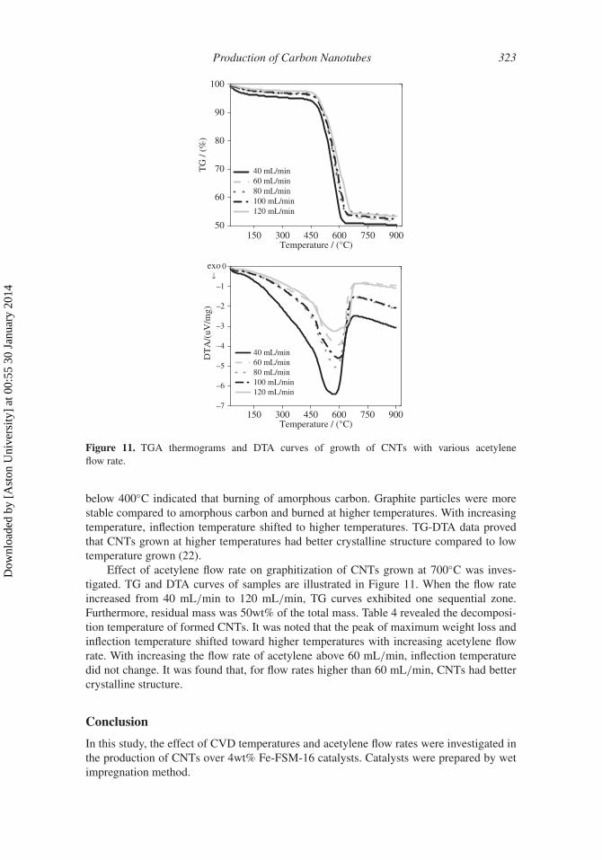
Figure 11. TGA thermograms and DTA curves of growth of CNTs with various acetyleneflow rate.
below 400◦C indicated that burning of amorphous carbon. Graphite particles were morestable compared to amorphous carbon and burned at higher temperatures. With increasingtemperature, inflection temperature shifted to higher temperatures. TG-DTA data provedthat CNTs grown at higher temperatures had better crystalline structure compared to lowtemperature grown (22).
Effect of acetylene flow rate on graphitization of CNTs grown at 700◦C was inves-tigated. TG and DTA curves of samples are illustrated in Figure 11. When the flow rateincreased from 40 mL/min to 120 mL/min, TG curves exhibited one sequential zone.Furthermore, residual mass was 50wt% of the total mass. Table 4 revealed the decomposi-tion temperature of formed CNTs. It was noted that the peak of maximum weight loss andinflection temperature shifted toward higher temperatures with increasing acetylene flowrate. With increasing the flow rate of acetylene above 60 mL/min, inflection temperaturedid not change. It was found that, for flow rates higher than 60 mL/min, CNTs had bettercrystalline structure.
Conclusion
In this study, the effect of CVD temperatures and acetylene flow rates were investigated inthe production of CNTs over 4wt% Fe-FSM-16 catalysts. Catalysts were prepared by wetimpregnation method.
Dow
nloa
ded
by [
Ast
on U
nive
rsity
] at
00:
55 3
0 Ja
nuar
y 20
14

324 S. Tas et al.
• Experiments were conducted at 500◦C, 600◦C, 700◦C and 800◦C, and the effect ofthe reaction temperatures was examined for CNT growth. Up to 500◦C, no CNTswere observed because of low carbon solubility in metal particles. Higher reactiontemperatures contributed to significant amount of carbon deposited on the catalystand carbon conversion due to enhance diffusion of carbon through the metal par-ticles. It was known that, at higher temperatures, large Fe particles formed anddiameter of the CNTs was increase.
• The effect of acetylene flow rate on CNT production of 4wt% Fe-FSM-16 at700◦C using 40 mL/min-120 mL/min acetylene flow rate was studied. The carbonamount deposited on the Fe catalyst increased until the acetylene flow rate reached80 ml/min and it was constant with increasing flow rate. This behavior was theresult of equilibrium of carbon concentrations between acetylene/metal interfaces.Moreover, SEM images demonstrated that CNTs diameter was almost same withincreasing acetylene flow rate.
• High-resolution transmission electron micrographs of samples revealed multi-layersidewalls of individual MWCNTs with diameter of 40 nm, in which hollow and tubalstructures were observed.
• Raman spectroscopical results clearly indicated that CNTs produced wereMWCNTs. Some of the formed CNTs were also examined by TGA for having anidea about quality of CNTs. Thermal decomposition differences were observed dur-ing the burning of CNTs. At low temperatures, CNTs started decomposition below400◦C due to burning of amorphous carbon. As the CVD, temperature increased,samples contained less amorphous carbon and more CNTs thus burning temper-atures shifted toward to higher temperatures. On the other hand, TGA resultssupported the Raman results for CNT production under different acetylene flow rate.It was found that inflection temperature was almost the same.
Acknowledgments
This work was supported by the Scientific and Technological Research Council ofTurkey (TUBITAK) with the Project No. 109M214. High-resolution transmission electronmicrographs of samples were kindly recorded by Prof. Dr. Christian Gspan of Institutefor Electron Microscopy and Fine Structure Research, Graz University of Technology,Steyrergasse, Graz, Austria.
References
1. Popov, V.N. (2004) Carbon nanotubes: Properties and application. Materials Science &Engineering R-Reports, 43: 61.
2. Somanathan, T., Pandurangan, A., and Sathiyamoorthy, D. (2006) Catalytic influence ofmesoporous Co-MCM-41 molecular sieves for the synthesis of SWNTs via CVD method.Journal of Molecular Catalysis A-Chemical, 256: 193.
3. Paradise, M. and Goswami, T. (2007) Carbon nanotubes — production and industrial applica-tions. Materials & Design, 28: 1477.
4. Zhao, Q., Li, Y.H., Zhou, X.P., Jiang, T.S., Li, C.S., and Yin, H.B. (2010) Synthesis of multi-wallcarbon nanotubes by the pyrolysis of ethanol on Fe/MCM-41 mesoporous molecular sieves.Superlattices and Microstructures, 47: 432.
5. Oncel, Ç. and Yürüm, Y. (2006) Carbon nanotube synthesis via the catalytic CVD method: Areview on the effect of reaction. Parameters, Fullerenes, Nanotubes and Carbon Nanostructures,14: 17–37.
Dow
nloa
ded
by [
Ast
on U
nive
rsity
] at
00:
55 3
0 Ja
nuar
y 20
14

Production of Carbon Nanotubes 325
6. Shanov, V., Yun, Y., and Shulz, M.J. (2006) Synthesis and characterization of carbon nanotubematerials. Journal of University of Chemical Technology and Metallurgy, 41: 377.
7. Dumanli, A. and Yürüm, Y. (2011) Carbon nanotube and nanofiber growth on Zn-based catalysts.Fullerenes, Nanotubes, and Carbon Nanostructures, 19: 155.
8. Kukovecz, A., Konya, Z., Nagaraju, N., Willems, I., Tamasi, A., Fonseca, A., Nagy, J. B.,and Kiricsi, I. (2000) Catalytic synthesis of carbon nanotubes over Co, Fe and Ni containingconventional and sol-gel silica-aluminas. Physical Chemistry Chemical Physics, 2: 3071.
9. Hernadi, K., Fonseca, A., Nagy, J.B., Siska, A., and Kiricsi, I. (2000) Production of nanotubesby the catalytic decomposition of different carbon-containing compounds. Applied Catalysis A:General, 199: 245.
10. Duesberg, G.S., Graham, A.P., Liebau, M., Seidel, R., Unger, E., Kreupl F., and Hoenlein, W.(2003) Growth of isolated carbon nanotubes with lithographically defined diameter and location.Nano Letters, 3: 257.
11. Klinke, C., Bonard, J.M., and Kern, K. (2001) Comparative study of the catalytic growth ofpatterned carbon nanotube films. Surface Science, 492: 195.
12. Ermakova, M.A., Ermakov, D.Y., Chuvilin, A.L., and Kuvshinov, G. (2001) Decomposition ofmethane over iron catalysts at the range of moderate temperatures: The influence of structureof the catalytic systems and the reaction conditions on the yield of carbon and morphology ofcarbon filaments. Journal of Catalysis, 201: 183.
13. Venegoni, D., Serp, P., Feurer, R., Kihn, Y., Vahlas, C., and Kalck, P. (2002) Parametric study forthe growth of carbon nanotubes by catalytic chemical vapor deposition in a fluidized bed reactor.Carbon, 40: 1799.
14. Cho, Y.S., Choi, G.S., Hong, S.Y., and Kim, D. (2002) Carbon nanotube synthesis using amagnetic fluid via thermal chemical vapor deposition. Journal of Crystal Growth, 243: 224.
15. Atchudan, R., Pandurangan, A., and Somanathan, T. (2009) Bimetallic mesoporous materials forhigh yield synthesis of carbon nanotubes by chemical vapor deposition techniques. Journal ofMolecular Catalysis A-Chemical, 309: 146.
16. Kobayashi, K., Kitaura, R., Kumai, Y., Goto, Y., Inagaki, S., and Shinohara, H. (2009)Fabrication of single-wall carbon nanotubes within the channels of a mesoporous material bycatalyst-supported chemical vapor deposition. Carbon, 47: 722.
17. Inagaki, S., Sakamoto, Y., Fukushima, Y., and Terasaki O. (1996) Pore wall of a mesoporousmolecular sieve derived from kanemite. Chem. Mater, 8: 2089.
18. Inagaki, S., Koiwai, A., Suzuki, N., Fukushima, Y., and Kuroda, K. (1996) Syntheses of highlyordered mesoporous materials, FSM-16, derived from kanemite. Bulletin of the Chemical Societyof Japan, 69: 1449.
19. Ghattas, M. S. (2006) Cobalt modified mesoporous FSM-16 silica: Characterization and catalyticstudy. Microporous and Mesoporous Materials, 97: 107.
20. Pollack, H. W. (1988) Materials Science and Metallurgy, Prentice Hall, Englewood Cliffs, NJ.21. Kukovitsky, E.F., L’vov, S.G., Sainov, N.A., Shustov, V.A., and Chernozatonskii, L.A. (2002)
Correlation between metal catalyst particle size and carbon nanotube growth. Chemical PhysicsLetters, 355: 497.
22. Chen, C.M., Dai, Y.M., Huang, J.G., and Jehng, J.M. (2006) Intermetallic catalyst for carbonnanotubes (CNTs) growth by thermal chemical vapor deposition method. Carbon, 44: 1808.
23. Dresselhaus, M.S., Dresselhaus, G., Saito, R., and Jorio, A. (2005) Raman spectroscopy ofcarbon nanotubes. Physics Reports-Review Section of Physics Letters, 409: 47.
24. Scaccia, S., Carewska, M., and Prosini, P.P. (2005) Study of purification process of single-walledcarbon nanotubes by thermoanalytical techniques. Thermochimica Acta, 435: 209.
25. Lee, C.J., Park, J., Huh, Y., and Lee, J.Y. (2001) Temperature effect on the growth of carbonnanotubes using thermal chemical vapor deposition. Chemical Physics Letters, 343:33.
Dow
nloa
ded
by [
Ast
on U
nive
rsity
] at
00:
55 3
0 Ja
nuar
y 20
14