Embed Size (px)
Citation preview

Copyright 2003, Offshore Technology Conference This paper was prepared for presentation at the 2003 Offshore Technology Conference held in Houston, Texas, U.S.A., 5–8 May 2003. This paper was selected for presentation by an OTC Program Committee following review of information contained in an abstract submitted by the author(s). Contents of the paper, as presented, have not been reviewed by the Offshore Technology Conference and are subject to correction by the author(s). The material, as presented, does not necessarily reflect any position of the Offshore Technology Conference or its officers. Electronic reproduction, distribution, or storage of any part of this paper for commercial purposes without the written consent of the Offshore Technology Conference is prohibited. Permission to reproduce in print is restricted to an abstract of not more than 300 words; illustrations may not be copied. The abstract must contain conspicuous acknowledgment of where and by whom the paper was presented.
The fatigue driven criticality of steel catenary riser welds requires attention to all aspects of their production and inspection. The miss match of pipe ends to be welded is one of the main fatigue sensitive sites for failure. Weld profiles are also another fatigue driven failure issue. Allowable defect size requires extraordinary attention to inspection issues such as wall thickness variations, and ultrasonic technology issues including material sound velocity changes, ultrasonic beam profiles and pipe surface condition. Each of these critical welds requires a “pedigree” that clearly defines constraints while documenting the essential properties of the weld. This paper discusses some of the critical issues and approaches to ensure the consistent production and inspection of steel catenary riser welds. Introduction Recovery of oil and gas from deepwater deposits requires the use of some type of floating production facility such as a Tension Leg Platform (TLP), FPSO, or other facility that is not rigidly secured to the sea floor. These facilities are designed to allow a certain amount of structure motion due to the environment. The steel catenary riser (SCR) pipelines that provide transport of product from the field to the facility or from the facility to onshore processing plants must be designed and constructed to maintain integrity even with long term exposure to fatigue damage from constant motion.
All aspects of the design, construction, and installation of these suspended pipelines must address the potential fatigue related failure modes. Issues that need not be considered for export pipelines resting on the seas floor or for pipeline risers attached to the fixed legs of stationary platforms now become critical design and construction issues for these suspended pipelines. Misalignment of the pipe ends prior to welding, which can represent an area of localized stress, is normally not a design factor for standard pipelines, and, depending on the applicable codes, can approach values of 2 – 3 mm. For SCR, this misalignment must be limited to 0.5 – 0.7 mm. This
requirement imposes limits on pipe end ovality and wall thickness variations.
Critical defect size for these SCR welds is much smaller than normally encountered for pipeline welds. With critical defect heights in the range of 0.5 –1.0 mm, the inspection requirements are much more stringent than those used for standard pipeline welds. To ensure accurate detection and defect sizing, specialized ultrasonic inspection is typically utilized as the inspection method. To provide sizing accuracy and resolution, many inspection variables must be closely monitored and controlled, including weld bevel tolerances, pipe wall thickness variations, ultrasonic beam profiles, and ultrasonic scanner stability as a function of position on the pipe.
There are many variables that must be addressed and controlled to ensure that SCR welds will maintain integrity during many years of exposure to cyclic loading. The variables must be addressed during all phases of fabrication and construction including material specifications, weld procedure development, pipe end sorting and matching, production welding and inspection, and installation. Most of the above variables are closely linked. For example, specifying a close end tolerance on riser pipe joints, to minimize pipe end misalignment, may cause the pipe mill to counter bore the pipe ends. This may have an unintended consequence if the riser pipe is installed by the reel method, because the counter boring may cause a greater strain concentration than the reduced misalignment was intended to avoid. In addition, there is a link between design requirements for an SCR and the construction aspects of an SCR. For example, the designer may conclude that a 200 year design life for the riser is adequate, with a safety factor of 10 to the life of the facility. But fatigue damage during installation must also be considered, and may well be a large contributor to overall damage. Fatigue damage can arise from the construction method, for example reeling (Ref 1), or from vessel motion during installation. Finally, to establish weld acceptance criteria, one must conduct the required fracture mechanics analyses to compute maximum allowable flaw size and compare this with the limitations of the NDE inspection system. However, one cannot simply take calculated maximum allowable flaw sizes from a fracture mechanics analysis and then translate these into weld acceptance criteria, without consideration of what constitutes sound welding practice.
Previous papers by the authors et al. (Ref 1 - 3) have addressed these issues to some degree or other. Since then,
OTC 15144
Production and Inspection Issues for Steel Catenary Riser Welds Frans Kopp and Gary Perkins, Shell International Exploration and Production, EP Projects; Garth Prentice, Shaw Pipeline Services; Donald Stevens, D.M. Stevens & Associates, Inc.

2 OTC 15144
SCR’s have practically become the riser type of choice to connect flowlines or pipelines to floating production systems, at least in the Gulf of Mexico. The objective of this paper is to look at SCR welds from a system perspective, taking into account design, pipe fabrication, weld procedure development, qualification testing, inspection, and ultimately production welding and installation issues. The following will be discussed:
- Fatigue issues in SCR welds, such as high-low, eccentricity, fracture mechanics analysis to establish a boundary of maximum allowable flawsizes.
- Full scale (or small scale) testing requirements. - Pipe end preparation issues, including surface
conditions, pipe end surveying and matching, and pipe end machining for ID matching.
- Pipe end alignment before welding for open and closed root.
- Welding, including root profile and cap profile considerations.
- Implications of wall thickness variations on AUT measurements.
- AUT for critical defect sizes. This paper will not discuss issues related to inspection of
specialty welds, such as internally clad pipe welds.
Fatigue Issues in SCR Welds Ref 1. presents a discussion of fatigue considerations for reeled SCR’s, but much of the discussion is also relevant for SCR’s installed by other methods. The principal approach for addressing fatigue of SCR welds used by Shell, is as follows:
1. Assume that welds can be made to satisfy the API X’ curve (more about this later).
2. Conduct frequency domain and/or time domain analysis of the SCR and determine if the required fatigue life of the riser (usually 10 times the design life of the facility) can be met using the API X’ S-N curve.
3. Identify “Fatigue Critical” regions of the SCR, which are usually a region in the sag bend and one near the top of the SCR. The extent of each “region” is defined by sensitivity analysis around various parameters and the separation between the “critical” and “non-critical” region is usually defined by the points at which the DOE F2 curve produces acceptable fatigue life. Care should be taken that less well defined loading conditions, such as VIV, or special conditions, such as reduced effectiveness of VIV suppression devices, are considered in defining the extent of the “critical” region.
4. Normally pipe end tolerances and weld misalignments are tight enough for both the critical and non-critical regions, and stress concentration factors from such tolerances are not added to the stress ranges used to compute fatigue life, at least not for comparison with the API X’ curve.
5. Once the design, using the appropriate S-N curve, has been finalized, the next step is to conduct sufficient fracture mechanics (FM)
analyses to determine maximum allowable flaw sizes.
The last step, FM analysis, requires further discussion. There are many more variables that affect the outcome of an FM analysis than the variables that determine the outcome of a fatigue analysis using an S-N curve. While the primary variables may be flaw size (height and length), some of the secondary variables are fracture toughness, stress concentration factor from the weld profile or weld misalignment, any plastic strain during initial installation that may result in tearing, materials da/dN curve and threshold stress intensity factors, flaw location within the weld, and maximum service stress that may result in a critical flaw size being reached. Because of the many variables, the results of the FM analysis may cover a broad range. To allow for a consistent approach across projects, Shell recently contracted with Southwest Research Institute to develop a Windows based program called FLAWPRO that allows the user to “play” with the above variables and immediately see the results in graphical form. This particular program also includes a calculation of damage that may occur as a result of plastic deformation of the weld during installation.
One can approach use of FM analyses in different ways. One can be called a “fit-for-purpose” approach; another is closer to a “modified workmanship approach”. The “fit-for-purpose” approach is to apply a very analytical methodology. This consists of 3 steps:
1. Determine maximum allowable flaw sizes for a given fatigue life requirement (usually length of the flaw is fixed, and the outcome of the analysis then is flaw through-wall height for the given length).
2. Determine the maximum expected measurement error of the inspection system.
3. Simply deduct the measurement error from the maximum allowable flaw size determined by the FM analysis, and this then determines the allowable weld acceptance flaw sizes.
While the above approach seems very clear and straightforward, there are pitfalls. The approach may result in fairly large acceptable flaw sizes. In general, allowing large flaw sizes, does not promote high quality welding practice. This promotes sloppiness, and there is always the possibility that there is a combination of weld flaws that can interact with weld misalignments and other flaws and create a stress intensity condition that is far worse than the fracture mechanics analysis considered. Further, while a strict “fit-for-purpose” approach may be acceptable for a regular pipeline weld, because the consequence of failure is only a shutdown of the facility to make a repair, failure of an SCR weld could have much more severe consequences. Finally, one always has to consider that the Probability of Detection (POD) of the NDE system may not be 100%. Therefore, it is possible, perhaps remotely, that a defect does not get detected or is sized well below the assumed measurement error. Intuitively, a weld that is made with a great amount of attention to high quality, and shows up clean on an inspection scan has a lower probability of having a defect that is severe, and may be shielded by a lot of “trash” in the scan and the extent of which would be undetected or underestimated.

OTC 15144 3
It is for these reasons that Shell continues to take a modified workmanship approach to establishing allowable defect sizes for SCR welds, even those in “non-critical” regions. The approach is almost the reverse of the “fit-for -purpose” approach above. First, based on the experience that we have had with various welding methods for SCR’s, we establish what are reasonable defect sizes. Through various development efforts over the past 10 years, we have become more and more confident about the sizing capabilities of certain AUT (Automatic Ultrasonic Testing) systems in critical regions of the weld (root and cap). We more or less set these sizing capabilities as desired weld acceptance criteria, but make adjustments to deal with expected flags from the AUT system that may oversize a flaw. Examples would be start-stops that are very short in length, but may result in a vertical height indication that is much greater than the actual flaw size. Other examples are interpass lack-of-fusion flaws with essentially zero height, but they may get flagged as having some height because of their orientation with respect to the sound beams from the transducers. We then compare what we consider “reasonable acceptable” flaw sizes with the results of fracture mechanics analyses. In most cases, we are considerably below the results of the FM analyses.
Finally, we consider the installation conditions. For onshore work that is not on critical path, little benefit may be gained from trying to push the allowable flaw sizes upwards close to the calculated FM curve. However, when we are offshore, we may be in a critical situation, where a weld cut-out may force us to either have to abandon the riser because of approaching inclement weather, and thus suffer significant downtime, or we may decide to go forward, but the delay from a weld cut-out may force us into a high-risk installation scenario, again with inclement weather approaching prior to safe transfer of the riser. Thus, for offshore work that is on critical path, we usually develop what we call Tier 1 and Tier 2 criteria. Tier 1 is what we would like to achieve, if achieving this quality does not place us at a higher risk elsewhere during installation. A Tier 2 criteria will allow slightly larger flaw sizes, and should only be used if in the judgment of the Shell Representative a weld cut-out of a weld that passes Tier 2, but does not pass Tier 1 criteria, would jeopardize the remainder of the riser installation.
While intellectually, this modified workmanship criteria may not appear all that attractive (after all we now include subjective judgment into the equation), it actually does fit quite well into the ALARP (As Low a Risk as Reasonably Practical) principle required by the HSE Management Systems that all major operators have in place. An allowance is made for the fact that if risks during offshore installation are small, and very high quality welds can be made, they should be made, but if the risk offshore for some reason becomes high enough, it is acceptable to pass a weld of slightly lower quality, provided it has been shown that such quality weld still has acceptable fatigue life. Full Scale Testing For the first application of an SCR to the Auger TLP, Shell conducted an extensive full scale testing program on 12” pipe welds, that formed the basis for selection of the API X’ curve
for design of steel catenary riser welds. A total of 33 test specimens were tested, each with 6 welds, thus exposing some 200 welds to fatigue loading. The welds were made, as much as possible, in a production mode, i.e. with misalignment tolerances and weld defects as close to what could be expected for the actual riser welds. A 3σ lower bound to the data fell right on the API X’ curve, supporting its use as a design curve. The reasons for selecting the API X’ curve were fairly simple: 1) the required fatigue life of the Auger SCR could only be achieved by using a curve, like API X’ (in other words, a more conservative curve like DOE F2 did not give adequate fatigue life); 2) we did not want to spend excessive effort and money trying to qualify to a better curve, like API-X, especially with the uncertainties of how to actually achieve superior welds in, an as yet untried, J-lay mode offshore; and 3) rather than selecting a design curve with parameters not readily recognized by design codes, it was convenient to select a design curve already established in an existing code.
Since then, Shell has conducted many more fatigue tests, both small scale and full scale. The following observations can be made:
1. By very carefully controlling the test coupon support conditions (gripping mechanism) and residual stress issues, small scale tests could be used to validate a weld procedure, but the overall cost of the small scale tests was not less than the cost of large scale test, especially with the new, high frequency resonance testing machines. Therefore, we only use full scale tests. In addition, by using full scale tests, the issue of sample size effect is dealt with (in other words, one does not need to worry as much as to whether coupons cut from full weld may not contain significant defects that would impact fatigue life of the full weld).
2. It is very difficult to make the pipe weld samples “as realistic” as possible, i.e. with typical production flaws included. This is one of the reasons for only accepting weld procedures that can produce “clean” welds in the hands of an experienced operator, and having acceptance criteria that only allow small flaws.
3. A properly executed fatigue test program is time consuming and costly, and invariably contractors tend to underestimate the cost of such a program. The tests themselves are usually the least expensive portion of the cost. The high costs are in making the welds, mobilizing NDE equipment and personnel, and transporting materials from one place to another.
4. No matter how many weld procedures we have tested, there seem to always be some surprises, so in general, each weld procedure that we have not qualified previously on similar type pipe and with the same contractor needs re-qualification.
One of the first questions that comes up is how many tests to conduct. The question is how much statistical relevance does one want to attach to the results. In general, by staying with a fairly conservative S-N curve like API X’, Shell’s approach has been that we need to have sufficient confidence

4 OTC 15144
upfront, prior to testing, that the results will easily qualify for use of the API X’ curve. Our standard specification requires a minimum of 9 welds to be tested to failure, at three different stress ranges. The mean curve from these 9 tests shall have a slope no steeper than the API X’ curve, and shall be at least 3σ above the API X’ curve. The standard deviation is that of the test results when plotted on a log-log scale.
Statisticians amongst the readers will probably object to such an approach, stating it is too simplistic, not totally statistically sound, etc. In fact, more statistically sound methods have been proposed and used by Shell for qualification to other S-N curves, but in those cases, an essential requirement was that the standard deviation of the design curve was known, such as is the case for the DOE curves. Such is not the case for the API X’ curve. So we are faced with either doing a very large number of tests, or to work with a simple, yet imperfect way of interpreting the data. The way we have approached this is to be cognizant of the pitfalls, and consider requests for deviation from the specification where it is considered conservative to allow this deviation.
For example, let’s take a set of 9 tests, and the slope equals the API X’ slope and the mean of the test results is at least 3σ over API X’. So the weld procedure is considered acceptable. Now let’s take another set of tests, with exactly the same results, except that one test at the highest stress range is a run out, and the weld is so good, that the inspector and the test lab decide to let the test run for a long time, until they are finally told to stop the test and use the number of cycles achieved at that time as test result. When the statistical analysis is conducted, results show that the slope of the test curve is less than that of API X’. So the second set of tests with actually better results, would not pass the criteria, while the first test did.
In our judgment, there are always possibilities that statistical analysis of a small sample of tests comes up with an answer that does not meet a specified requirement, but the statistical analysis is only one, and not the sole tool to determine acceptability of the tests. From the years of experience that we have had with testing various welding procedures, the evidence that we have found is that a clean weld, with a good cap and root profile and tight control of alignment, and sufficient passes, will produce an acceptable weld by a large margin to API X’. Results that are very close to the margin, do not come unexpectedly and in many cases, such welds should not have been subjected to testing to begin with. More work should have been conducted to optimize the welding procedure, prior to making fatigue test samples.
One of the failure initiation points is illustrated by the surprises Shell had during the many test programs on SCR quality. On nearly all the Auger SCR test welds made with a manual process or with a mechanized wide bevel angle, failure originated at the root. The first set of mechanized weld tests demonstrated failures also tended to occur most frequently at the root of the weld. However, those automatic (GMAW) welds had a 27 degree weld bevel and were thus similar in nature to the Auger SCR welds. However, when narrow gap automatic welding processes were introduced, there was an almost 50/50 balance between failure origination in the root and failures at the toe of the cap, thus requiring much more
attention to the cap transition. Mechanically speaking, this shift makes sense. The toe of the cap on a narrow groove weld is much closer to the weld centerline, in fact almost as close as the root pass, and thus stress concentration from weld misalignment will have just as much effect on the toe of the cap as it has on the root, whereas for a wide bevel, such stress concentrations will have practically disappeared at the toe of the cap. It is also more difficult in a narrow groove weld to get a smooth cap transition, especially for a 2G (J-lay) weld, so local geometric stress concentrations start to play a bigger role. Pipe End Preparation As previously mentioned, pipe alignment is critical to the life of SCR girth welds. Therefore, it is of utmost importance to provide welders with dimensionally matched pipe ends. Otherwise, the welders cannot produce SCR quality welds.
Dimensionally matched pipe ends can be achieved a couple of ways. (1) Measure pipe ends and sort pipe to match ends. (2) Measure pipe ends, determine a common inside diameter and wall thickness, and machine pipe ends to match them. Measure and Sort Approach. The purchase of line pipe with end tolerances “better than” standard API 5L end tolerances make it possible to measure pipe ends and sort pipe to match ends. Project specific line pipe specifications, spelling out pipe end tolerances with select pipe manufacturers that can meet the “better than standard end tolerances” are required. Additional in-mill measurement systems may need to be implemented to assure that requirements “better than” API 5L are being achieved.
A population of the line pipe larger than that required to fabricate the SCR must be segregated. Measurement of the end dimensions of the segregated pipe are taken and recorded. Measurement can be performed manually or can employ measuring machinery. The measurements are then sorted based on inside diameter and wall thickness into groupings that will allow pipe end matching meeting the SCR misalignment tolerances. Because all pipe ends may not fit into one grouping and yield the required limits on misalignment (0.020” – 0.030”), there will be multiple groupings, with each grouping meeting the requirements and only specific pipe joints having the two end measurements that satisfy the requirements of transitioning the two groups. (End A satisfies group 1 while end B satisfies group 2). Since unique pipe joint ends are now required to satisfy the matching requirements, the complete riser configuration according to pipe joint numbers must be specified before actual construction of the riser. An engineering drawing of the complete riser is constructed where individual pipe joints are assigned to specific locations in the riser and all other dimension critical components, including buckle arrestors and/or J-Lay collars, are included. Since all components have been previously measured for end dimensions, the engineering drawing provides a detailed “build-to” guide that will automatically insure that the internal misalignment and wall thickness variation limits are achieved. Although considerable effort is invested in developing these engineering drawings, the benefits of the investment are readily apparent in the time
OTC 15144 5
savings during construction, since pipe selection is pre-defined to assure design required end alignment. Measure and Machine Approach. There are cases when the “measure and sort” approach does not achieve the groupings required to meet the misalignment and/or wall thickness variation constraints. Achieving the results strictly by grouping is especially difficult with thick-walled seamless pipe. Since the misalignment and wall thickness variation constraints are absolutes, another approach to meet these requirements must be employed.
All pipe ends must still be surveyed to determine minimum and maximum internal diameters and wall thickness ranges. Based on the results, one or more “new” minimum internal diameters may be defined. Figure 1 illustrates, with exaggeration, the issues being addressed. For the case of seamless pipe, in many cases, the ID and OD are not concentric, resulting in significant wall thickness variations within the pipe end. The thinnest wall values still meet the API 5L requirements, but the thickest values may exceed the nominal wall thickness values by 15-20%. The new counter bored machined ID, with a slightly different center location, usually concentric with the original OD, will result in a slightly larger ID, but more uniform wall thickness. This machining requires specialized tooling that centers on the pipe OD versus the typical approach of alignment using the pipe ID. Analysis of the pipe end survey will yield one or more defined machined ID’s that will achieve the designed ID misalignment and wall thickness variation limits.
Figure 1 – Counter boring to Achieve ID and WT matching
Figure 1 illustrates that the machining may result in material being removed from only part of the ID whereas other portions of the pipe ID may have significant material removal. The machined surface and transition area from the counter bored to original pipe surface must receive final surface smoothing through polishing to assure that all significant cutting tool marks and all transitions are smooth and do not represent stress concentration areas.
Figure 2 illustrates a typical SCR pipe machined end where only portions of the ID have been impacted by the machining process.
Figure 2 -- Typical ID Counter Boring (change aspect ratio!!)
The “match and machine” approach will result in groups of pipe end ID’s that can now be matched to achieve the requirements. But, as noted in the introduction, solving the end matching problem may introduce other issues, depending on SCR installation method. Shell has determined that the machining approach cannot be utilized without possibly a large penalty on strain amplification if the SCR is to be installed in the reeled mode and strains exceed 2%. The area of transition between machined ID and original ID pipe surface represents an area of strain concentration where deformation and possible tearing can occur during pipe reeling. For this reason, generally only the “sort and match” or minimal machining can be utilized when SCR installation is via reeling.
Many of the current deepwater projects utilizing SCR’s require large diameter, thick wall pipe. These pipe requirements can only be met with double-submerged arc welded (DSAW) pipe constructed from rolled plate. The use of rolled plate assures minimal wall thickness variations, but the pipe manufacturing process may introduce the phenomena called “peaking” or other issues at the long seam weld. The “peaking” phenomena results in a localized area with abrupt change in diameter causing significant mismatch with typical pipe ID’s. In many cases, the only solution to eliminate this localized mismatch, and localized stress concentration, is to align the seams of the pipe ends. The DSAW process and subsequent trimming and grinding of these seams to accommodate ultrasonic inspection may also result in flat spots on the pipe ID, OD, or both. Again these abrupt changes in diameter results in localized stress concentration that may only be addressed by seam alignment.
Finally, it should be recognized that specifying tight pipe joint end tolerances may still require special measures for J-lay installation. Many times, a pipelay contractor requires a pipe pup to be welded on top of the J-lay collar that is used to support the pipe during installation. This pup needs to be cut from pipe joints. On seamless pipe, a tight pipe joint end tolerance does not guarantee any such tolerance more than a few inches from the joint end. Thus, having to cut pipe joints, either for insertion of J-lay collars, or because total joint

6 OTC 15144
lengths for a quadruple or hex joint are longer than the J-lay system can handle, will complicate the sorting program. Pipe End Measurement Before Welding Pipe end sorting or the machining of ends results should provide minimum miss-match when aligned at welding. After alignment prior to welding, the miss-match must be measured to assure that all tolerances are met. Depending on the type of welding process and bevel preparation used, this measurement can be performed using mechanical or other methods.
Figure 3 -- Open and Closed Root Bevels Figure 3 shows the two basic types of bevel configuration
that are utilized for SCR weld production. Welding processes that utilize most manual or semi-automatic processes (manual shielded arc, manual tungsten inert gas, semi-automatic gas metal arc) provide a gap between the weld bevels after alignment. This gap facilitates the use of mechanical measurements using precision calipers or other instruments that can be inserted into the gap and provide a measurement of the differences in height of the internal diameter at various locations around the bevel. This difference in height represents the amount of miss-match or high/low that will be in the completed weld. By measuring numerous locations around the bevel circumference, the maximum miss-match can be ascertained.
For welding processes that utilize a closed bevel configuration, to ensure there is no gap at the pipe internal diameter, other methods must be employed to measure the weld miss-match. All of the closed bevel welding processes utilize some type of bevel profile that results in a step above the root vertical face. One mechanical approach that can be utilized with the closed gap configuration is the following:
- measure the vertical height of the root face at several locations around the circumference on each pipe end before fit-up and document
- after fit-up, measure the differences in height of the vertical face of the root on each bevel
- the differences in the vertical height of the root faces, corrected for any differences in actual height of the faces, represents the miss-match at the weld internal diameter
Figure 4 -- High/Low at Root
Figure 4 illustrates the differences in height of the bevel
shelf due to ID misalignment while Figure 5 illustrates the approach for measurement using calipers or modified hole gauges.
The mechanical measurement of high/low on closed bevels is extremely time consuming requiring measurements with close tolerances to be performed with limited access and the comparison of a large number of data points.
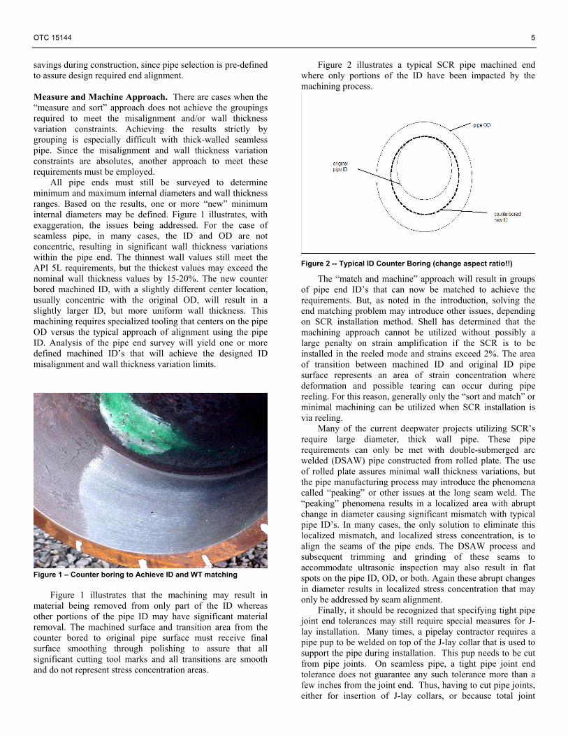
Another approach to quickly measure high/low when closed zero gap bevels are used is to utilize ultrasonic technology to measure the required parameters. One patented approach using ultrasonics is presented in Figure 6.
Figure 5 -- Mechanical Measurement of High/Low
By measuring various pipe wall thickness values and distances to the pipe outside diameter from an arbitrarily oriented reference line, the actual miss-match near the weld bevel can be determined. Figure 6 shows such a system being used in the welding station prior to welding. This mechanized approach also has the benefit of automatically providing a hardcopy record of the miss-match at locations around the weld, with measurements every 1 mm. One limitation of this approach is that the ultrasonic approach cannot be applied directly at the weld centerline, since the measurements must be performed on the full pipe body wall. Any small changes in
OTC 15144 7
the pipe internal diameter, within 6-8 mm of the bevel, will not be detected by this method.
Figure 6 – Automated Hi/Lo Measurements Welding. Size and population of weld flaws, weld and heat affected zone fracture toughness, weld tensile strength, and weld root and face geometry influence SCR girth weld fatigue properties. Therefore, SCR welding procedure qualifications are very important. Minimum weld, heat affected zone fracture toughness and strength must be assured with thorough testing. Weld flaw sizes and population must be determined during qualification testing. The welding procedure parameter ranges usually must be severely limited to assure weld flaws meet SCR quality requirements. And welders must be given the opportunity to learn and practice using the weld procedure to prevent excessive production weld cut-outs. As previously presented, SCR girth welds must meet fatigue requirements as proven by testing. SCR welding procedures and production welding are controlled to assure production welds have fatigue properties similar to the girth welds tested.
SCR weld procedures are qualified using testing requirements exceeding those used for pipeline weld procedures. Size and population of weld flaws, weld and heat affected zone fracture toughness, weld tensile strength, and weld root and cap geometry influence SCR girth weld fatigue properties. All of these weld attributes are determined during weld procedure development and qualification testing.
During weld procedure development; qualification testing; and the welding of fatigue test samples, sensitive automatic ultrasonic inspection can be supplemented with radiographic inspection to determine flaw location, size, and population. Radiography sometimes supplements the automatic ultrasonic inspection to confirm porosity. The weld procedure must demonstrate that it can produce welds that repeatedly meet the restrictive SCR weld flaw acceptance criteria. Many times it has been necessary to section welds during weld procedure development to show the welding contractor the automatic ultrasonic inspection technique is in fact finding weld flaws that for pipeline welds would not be considered detrimental but cannot be accepted for SCR welds.
It has been shown that the welding parameter ranges must be restricted in order to repeatedly meet the weld flaw acceptance criteria. Whereas pipeline standards such as the Appendix - of API 1104 allow qualification of heat inputs over a broad range, for SCR welds to meet the NDE requirements, these welding parameters must be tightly controlled. Pipeline contractors want the widest range possible to address typical pipeline production welding issues such as high/low and wall thickness variations. Since high/low and wall thickness variations are strictly controlled, the consequences of restricting the welding parameter ranges are typically not as severe as the contractor fears. However, these restricted welding parameter ranges and implementation of the required measurement and monitoring controls result in weld productivity reductions that should be considered by the welding contractor.
It has been shown many times that controlled grinding techniques must be used for welds to meet the SCR weld flaw acceptance criteria. The controlled grinding techniques become part of the procedures required to make SCR quality welds. Improper grinding of start/stops can result in lack of fusion flaws that, albeit short, have heights and lengths not meeting SCR weld flaw criteria. Ground areas must allow the weld puddles deposited over them to fuse to the sides and bottom. The slope of the ground area must be controlled through the entire area of the grind. This requires controlled ground area slopes from the bottom of the ground area to the previous bead height. Also, the width of the ground area must be controlled.
SCR weld and heat affected zone fracture toughness are determined using Charpy V-notch testing and CTOD testing during weld procedure qualification. Charpy V-notch testing temperatures and required results vary by project requirements. Along with controlled welding parameters, the use of line pipe purchased with Charpy V-notch requirements and the use of welding materials that produce welds with good fracture toughness properties when tested at the project required test temperatures provide weld procedures meeting the Charpy V-notch requirements. SCR welds made for Shell must meet a minimum 0.015 inch CTOD value with an average 0.020 inch value. CTOD testing is conducted in accordance with the API 1104 Appendix. To meet the CTOD requirements, it has been necessary to alter pipeline welding procedures. Almost always, the welding procedures that must be followed to meet the CTOD requirements require restricted parameter ranges resulting in lower weld productivity.
Tensile specimens tested during welding procedure qualifications must fail in the pipe body and not in the weld area. This would suggest that the weld must exhibit the absence of critical flaws in order to provide a level confidence as to the validity of the test. We know welds are not perfect. This requirement that tensile test specimens fail in the pipe material provides the assurance that weld flaws are surrounded by material stronger than the base pipe material.
Smooth root and cap profiles are critical to fatigue life of welds. As mentioned earlier, fatigue failures initiate at either the root or cap areas. The root and cap re-entrant angles must be controlled to prevent a mechanical notch effect at the weld toes. In a similar manner, the root and cap heights must be controlled. Figure 7 illustrates an unacceptable cap profile

8 OTC 15144
and Figure 8 illustrates an acceptable cap profile. As shown, a strip pass cap may be required to assure a good cap profile. The strip pass cap will require additional weld passes resulting in reduced productivity, and the welding contractor must recognize this. Weld caps can be carefully sanded to meet the required profile and to facilitate nondestructive examination interpretations. However, this sanding process is not as simplistic as removing some of the cap re-enforcement since the critical fatigue area for the cap is at the interface of the cap toe and re-enforcement re-entry point. The cap re-enforcement must be removed and any evidence of the cap toe lines must also be removed by sanding so that magnetic particle testing does not reveal any evidence of the cap toe when correcting unacceptable re-entrant angles. Since this sanding can be a time consuming process, the obvious solution is to qualify a welding procedure with acceptable cap profiles for the complete weld. With a sound procedure that addresses the cap profile, experience has shown sanding of weld caps is infrequent and can be done locally if anomalies are found during nondestructive testing.
Figure 7 – Unacceptable cap due to wall thickness variations and use of puddle cap process
Each weld must use a fresh, machined bevel. Any touch-
up to weld bevels using a grinder must be carefully controlled. As with start/stop grinding, any ground areas must be controlled to assure lack of fusion flaws do not occur due to non-uniform bevels. The bevel touch-up techniques must be part of the welding procedure qualifications.
Pipe joint ends cannot have residual magnetism that will interfere with welding. Pipe ends can be checked for residual magnetism and ends found unacceptable must be degaussed. Or, all pipe ends can be degaussed just before welding without prior checking. Residual magnetism should be considered even when the line pipe is purchased with specified maximum residual magnetism at the pipe ends. Pipe can become magnetized during shipment and handling after it leaves the pipe mill.
Welding processes used for SCR welds have included shielded metal arc (SMAW), gas tungsten arc (GTAW), submerged arc (SAW), and gas metal arc (GMAW). It is well known that all of these processes have strengths and weaknesses. Productivity and sidewall and inter-run lack of fusion flaws are big concerns for SCR welds. Welding power
supply manufacturers continually improve their products to enhance arc characteristics. No magic welding power supply has been found for producing SCR quality welds. For the automatic GMAW process, the use of a modified short-circuiting arc transfer technique for root passes has been used with mixed results. It provides a very good root bead profile, however, it has been found to be a very “cold” welding process, requiring special care to prevent unacceptable lack of fusion flaws. The use of an open gap root bevel can lead to centerline flaws in the root area that must be considered during nondestructive examination. These centerline flaws can easily be missed if the automatic ultrasonic testing technician is not cognizant of the fact that they are inherent to the welding technique.
Figure 8 -- Strip cap provides SCR desired cap profile
Shell generally does not allow repairs to SCR welds.
Cosmetic repairs to accessible root beads and to cap welds can be made with case by case approval from the welding inspector. One of the reasons that Shell has not allowed for more significant weld repairs is that such repairs introduce a whole new set of variables, including metallurgical changes, that would be very difficult to capture by limited sample fatigue testing.
The contractor must be aware of the requirement for cutouts as opposed to performing repairs in the presence of unacceptable defects. This requirement provides incentive to use weld procedures that are tightly controlled to limit weld flaws and to use highly trained and skilled welders.
It has been repeatedly found that SCR weld productivity has been greatly influenced by the amount of training and practice time afforded the welders. Productivity has been greatest when the welding contractor allowed the SCR welders to (1) properly train using the equipment used during SCR production welding, (2) practice making many girth welds inspected using the production nondestructive examination techniques and acceptance criteria, and (3) begin interpreting pipeline production welds preceding SCR welds to the pipeline and the SCR weld flaw acceptance criteria with direct feedback of interpretation results to the welders. Item (3) allows the welders time to adjust their mental processes to

OTC 15144 9
consider the tighter weld controls and welding techniques to result in SCR quality welds.
All of the extraordinary efforts addressing SCR welding are to assure SCR welds meet required mechanical properties and quality. This includes our company inspectors witnessing each SCR weld made. The inspectors monitor all welding parameters assuring each weld is made in accordance with the qualified welding parameters. Monitoring includes measuring and recording the high-low of each weld fit-up. No weld is made unless the weld fit-up meets the SCR requirements. Welds with heat inputs outside of approved ranges are subject to cut-out. The witnessing of each SCR weld by our inspectors is not only to assure mechanical properties and weld profile but also to prevent weld flaws. The total monitoring of the welding process, including the physical dimensions and complete welding parameter set, coupled with stringent AUT of the weld, results in a “pedigree” for each weld that assures that all production welds are within the family of welds that met the qualification and fatigue performance testing.
Shell’s overall philosophy has been and continues to be that it is better to prevent weld flaws than to inspect for them. In our history of having many SCR welds made, using different welding processes, we have found that initially there would often be some resistance from the welding contractor and welders to the tight quality control, but the result has been that the SCR welds have been extremely flaw free. This absence of weld flaws makes ultrasonic interpretation of girth welds possible. The weld flaw acceptance criteria make it difficult for the interpreter to sentence welds with many flaws. SCR welds with many flaws that must be reviewed and interpreted require extreme interpretation diligence by the technician. One of the hardest things for the welding contractor to deal with is to switch from a high-production pipeline to a very high quality SCR weld mode, where things like proper pipe end alignment prior to welding takes up to five times the time it would take to align pipeline quality welds. There may be resistance to add more weld passes to obtain higher quality welds. A simple illustration, however, would show that adding a third cap pass in a 2 G weld to get a smoother cap profile, may add just 1 more minute to welding time. If just one weld cut out at easily 6 hours for a cut-out can be avoided, that is the equivalent of 360 welds with an extra cap pass, many, many more 2G welds than need to be made in an SCR. Offshore, avoiding a cut-out is the overriding concern, and unless the contractor resets his mind to produce superior quality welds, with speed as a secondary goal, the result can be disappointment for owner and contractor alike.
- Wall Thickness Variations. Previous figures have graphically illustrated welding issues that occur when slightly different wall thickness pipe ends must be welded. Cap profiles are unacceptable and significant areas of stress concentration are produced. Trying to produce the SCR defined near perfect weld while operating within the narrow operating limits constrained by limited heat input variation is not possible with significant wall thickness variations. Wall thickness variations may also have significant impact on the ultrasonic inspection.
Ultrasonic Inspection Requirements for Critical Defect Sizing AUT Technology Overview. Shell has examined the different inspection transducer approaches: focused transducers, unfocused transducers, time-of-flight-diffraction (TOFD) and phased array to determine benefits and limitations for the unique application of SCR welds. All of these approaches have been and are being used successfully for standard pipeline inspection. But all the systems have limitations when used for the critical application for SCR’s. Stand alone TOFD systems suffer from the fact that TOFD may overemphasize volumetric defects; is incapable of detecting and sizing critical near surface defects; and depending on defect orientation, may significantly miss-size certain types of defects. Unfocused transducer systems using only time-of-flight and amplitude data cannot provide the level of sensitivity or accuracy required to operate to SCR criteria. Phased array based systems hold promise but as yet no database exists that demonstrate their capability to operate to the constraints of SCR criteria. Fixed frequency limitations with phased array systems may also have an impact on detection and sizing depending on certain weld profiles. Shell has established confidence in the use of focused transducer arrays, especially for accurate sizing of near bevel defects at the critical surface areas, coupled with high frequency TOFD as a safety net to assure detection of anomalies.
AUT systems for girth welds rely on a scanning mechanism that transports an array of probes around the weld circumference. The composition of the array is configured based on detection and characterization of machined notches and holes in a calibration standard constructed from SCR pipe. Based on testing and destructive analysis of defective welds, a correlation between the array responses to the machined defects and typical defects encountered during production can be established. Because of the sensitivity to wall thickness variation issues noted earlier, the pipe sample to be used for construction of the calibration standard must be carefully selected to assure that any wall thickness variations to be encountered in production welds are addressed.
Calibrating the AUT system consists of optimizing the response of each transducer from its associated reflector and setting this response to some nominal value, such as 80% of full scale height (FSH) on the ultrasonic display. Variations in pipe surface condition, stability of probe to pipe surface contact as a function of orientation, and changes in relative position of the transducer to reflector all impact the response values. All of these variables must be eliminated or controlled to assure consistent responses to the calibration reflectors.
Once it is demonstrated that the responses to the machined reflectors in the calibration standard are consistent, the major challenge is to assure that inspection of the production welds also have the same level of controls imposed. The responses to the calibration reflectors require positioning the scanner such that the transducers are at a predefined location relative to the theoretical weld centerline. During production, before the pipe ends are aligned, a precise scribe must be place on one or both pipe ends to provide a reference for positioning relative to the production weld centerline. Scanner alignment relative to this reference line is critical to assure consistent and accuracy defect sizing. Once

10 OTC 15144
positioned, the scanner is moved around the weld circumference at the same speed as was used for calibration.
During production inspection, the AUT system must provide information to the operator that verifies that the scan is consistent and reliable. As noted, scanner positioning is critical. The AUT system responses to certain features of the production weld, such as responses to the root and/or cap re-enforcement reflectors, must be used to verify that the scanner is centered on the weld. Typically these responses are ignored or even gated out of the display for pipeline weld inspection, but for SCR welds, these “geometric” reflections must be used to assure proper alignment during production scanning. Since SCR welds require the root and cap re-enforcement have smooth contours to eliminate stress concentration areas, modifications to typical displays are required to assure that these geometric features are detected and monitored.
The system must also provide assurance that all transducer data are reliable at each inspection increment (1mm) around the weld circumference. This function is usually performed through independent “coupling monitoring” channels which act as independent checks that each transducer is functioning properly. This check will flag when there is a transducer malfunction or when a property of the weld or pipe does not allow consistent inspection. One example of a coupling monitoring flag occurs when the localized pipe surface condition (pitting, scale, etc.) does not allow consistent sound transmission into the pipe. Typically these areas are short; occur infrequently; and for the most part are ignored when inspecting pipeline welds because the short lengths of ineffective inspection are minor compared to typical acceptance criteria. For SCR welds, coupling flags become critical because ineffective inspection, even for short lengths, could mask a critical SCR defect. The operator must eliminate or address every coupling flag to assure no critical defect is ignored. AUT Inspection Requirements Necessary for the Inspection of Steel Catenary Risers. To produce welds that will meet the stringent requirements demanded for SCR’s, constraints are imposed on pipe materials, pipe end dimensions, and welding processes. Similar constraints must be imposed on the inspection process to assure that critical defects are always detected and adequately characterized. As noted earlier, the height of these critical defects may only be in the range of 0.5 – 1.0 mm. This range represents defect heights that may be ignored or considered insignificant when inspecting to standard pipeline criteria. Detection and characterization of defects of this small size range require operating at the limits of ultrasonic inspection technology. Reliable and consistent results can be provided only if strict controls are imposed on the inspection process. All aspects of the process must be addressed at a more precise and detailed level than what is required or expected for typical pipeline weld inspection. Areas that must be addressed include:
• System selection for SCR weld inspection • Transducer selection to assure reliable detection and
sizing accuracy • Selection of material and design of the
calibration standard
• AUT system response and consistency to calibration standard reflectors
• Controls during production weld scanning • System checks during production weld scanning to
assure adequate detection and sizing • Data interpretation based on previous correlations
with destructive results from actual defects • “Safety nets” to assure any anomalies in the data are
recognized, flagged, and addressed • Operator experience and access to
supporting information The use of AUT for pipeline weld inspection has become
the standard NDE approach offshore, particularly when mechanized welding processes are used. Numerous articles (see ref 3) have detailed the benefits of using AUT and will not be repeated here. There are major differences in system requirements when inspecting pipeline welds to a particular regulatory standard such as API 1104 as opposed to the requirements that must be met for SCR weld inspection. For pipeline inspection, industry standards, such as DNV OS F101, Appendix E (Ref 5) have been developed that define a rigorous qualification program, which, when executed completely, will define an AUT system’s capability for pipeline inspection. These standards address pipeline inspection needs but as yet have not been tailored for the specific requirements necessary for SCR weld inspection.
There are two primary concerns when discussing the issues of defect sizing during the AUT inspection of pipeline girth welds. The first is the minimum sizing capability of the ultrasonic inspection system, the second being the accuracy of sizing. Acceptance criteria’s for weld quality are developed on the premise that these are well defined. The difficult part resides in quantifying the ability of the many systems and technologies available today. The only tangible method to determine the sizing limits of the AUT vendors is through inspection programs combined with destructive sampling. A caution should be considered when discussing minimum sizing capabilities. Many AUT systems can provide evidence of the ability to detect small indications but do not provide practical methods of applying those detection methods in a production environment. The dilemma then becomes the calling of unnecessary weld repairs due to over sensitivity of the system. The only way to provide a suitable approach to high resolution sizing is through the application of prudent technology combined with the proper control over all inspection variables.
Shell performed considerable “in-house” work to determine capabilities and limitations of the various AUT systems before embarking on the use of AUT for SCR welds. Once specific system and contractor were selected, much effort was further devoted to define the controls necessary to assure reliable inspection to a stringent SCR criteria. The resulting database has provided Shell with a high level of confidence that SCR welds can be reliably inspected with AUT.
Flaw Sizing and Supporting Sizing Programs. Flaw sizing and Automated Ultrasonic Testing have been issues of an ongoing debate for a number of years. As mentioned

OTC 15144 11
previously, the most tangible way of determining an individual contractors sizing ability is through recognized proving programs in addition to sizing studies performed during weld procedure qualifications. Today, a number of companies provide automated ultrasonic inspection services, with the majority utilizing different technologies while providing varying degrees of sizing capabilities. Many pipeline owners and installation contractors have implemented AUT proving programs. Unfortunately, no formal program was initiated to consolidate the data from the various programs. Accumulating and consolidating the data after the fact presents significant challenges due to ownership of the data, location and format of the data, and the methodology of proving program. The sizing data presented in this paper represents a combination of a portion of data accumulated by Shell along with data selected from four other proving programs all using the same AUT contractor. The samples were selected based on the ability to provide supporting documentation in the form of archived inspection charts along with macro photographs for each sample. Each one of the five proving programs was performed by third party entities, this includes both sectioning and data correlation. The following figure presents the consolidated data in the form of a scatter chart.
Defect Sizing Accuracy - With +/- 1 mm Ranges
-2
0
2
4
6
8
10
12
0 1 2 3 4 5 6 7 8 9 10
Defect Height (mm)
Defe
ct H
eigh
t (m
m)
Measured Defect HeightOver Size ToleranceReported Defect HeightUnder Size Tolerance
Figure 9: Defect Sizing Accuracy With +/- 1 mm Extents Although this chart produces some very conclusive results attesting to the particular AUT vendors sizing accuray, this may still not satisfy the requirements for SCR inspection. A portion of the industry has adopted the philosophy that defect sizing should be classified in terms of a plus-minus of a defined defect size (E.G.. +/- 1.0mm). This view provides limited insight into the actual sizing capabilities of a specific AUT vendor or technology to address specific inspection requirements not only for flowlines but more importantly the detection necessary for SCR inspection. Shell has worked with one AUT supplier that defines accuracy based on a specified inspection zone or height. This approach suggests that a sizing accuracy should be evaluated as a percentage of designed zone or plane height. Simply described, the greater the number of inspection zones or planes for a given wall thickness, the better the sizing accuracy. If an inspection zone is designed to interrogate a zone height of 1.0 mm and the sizing accuracy is within 30% of that zone, the sizing accuracy would be +/- 0.3 mm. If the zone height were increased to 3.0 mm, accuracy
would be +/- 0.9 mm. If the zone height is further increased to 5.0 mm, accuracy for that zone would be +/- 1.5 mm. This approach requires the correct selection and application of suitable focused transducers. To obtain the highest resolution inspection, the weld should be divided into as many zones as practical while applying transducers that exhibit beam profiles consistent with the designed zone heights. Although a plus/minus reference to defect sizing has been presented it is not the plus (over-sizing) tolerance that remains critical but the negative (under-sizing). Acceptance criteria are affected by the negative sizing tolerance and not the positive. The concern for over-sizing is still valid from a productivity (repair) standpoint, but not from a weld integrity perspective. To provide adequate sizing for a given application, inspection zone heights should be altered accordingly. Such is the case when dealing with the inspection of SCR’s, where high resolution is required in both the root and cap regions (surface breaking). In some more critical applications root zones have been designed to a height of 0.5 mm providing accuracy in the range of 0.2 to 0.3 mm. In these cases additional calibration reflectors and alternate sizing algorithms are used. The defect size with respect to zone height concept extends further as defect interaction with the pipe surface can also be a concern. This suggests that zone or plane heights at or close to the surface should be designed as small as practical limits will allow, but can increase when approaching the weld centre. It should also be noted that acceptance criteria typically becomes more relaxed in buried regions of the weld. Understanding the Data Presented. Unfortunately, not all the data provided from the various proving programs incorporated the percentage of zone height method as the basis for evaluation. In order to incorporate this concept into the data, defect breakpoints were provided at the commonly accepted points for critical applications. This provides a conservative evaluation of the data, as sizing accuracy is based on the smallest zone height. Correspondingly, defect sizes in each synthetic zone would demonstrate the tightest sizing in terms of percent of defect height. It should also be noted that all the data presented was not extrapolated from SCR proving programs. This introduces another level of conservatism as all inspection zone heights may not have been designed as small as would normally be required for SCR inspection. The first exercise was to identify the zone height breakpoints. As we are discussing SCR inspection breakpoints were determined as follows;
1. Zone heights 0.1 mm through 0.5 mm 2. Zone heights 0.6 mm through 1.0 mm 3. Zone heights 1.1 mm through 2.0 mm 4. Zone heights 2.1 mm through 3.0 mm 5. Zone heights 3.1 mm through 6.0 mm 6. Zone heights 6.1 mm through 9.0 mm
The consolidated data discussed previously, was then further evaluated based on these zone heights or breakpoints.

12 OTC 15144
The results derived from the compilation of the various proving programs produced some very conclusive information. It provided quantitative support that defects smaller than 0.5 mm could be detected and sized. It also confirmed that as the inspection zone height sizes are reduced the sizing resolution increases, again, necessary for critical applications. Additional Inspection Variables Encountered for SCR Inspection. With the use of DSAW pipe for construction of SCR’s, coupling flags have become a prime issue that must be addressed. As noted in a previous section, the peaking or flatness associated with the long seam may represent geometric features that inhibit proper coupling monitoring. For pipelines, these coupling flags at long seams are readily ignored as being due to the unique geometry at the long seam. For SCR welds, Shell has investigated in detail the localized ultrasonic properties at the long seams. Testing has verified that most of the coupling flags typically attributed to long seam geometry are actually due to differences in the acoustic properties of the long seam compared to base pipe material. These changes in acoustic properties cause the ultrasonic inspection, valid everywhere when inspecting through base pipe material, to be invalid at the long seams. Unless addressed, defects 20 – 40 mm in length and with significant height can be missed at the long seams due to these acoustic changes. Additional transducers on the production scanner, or an independent scanner for use at the long seam, must be configured to address the unique acoustic properties at the long seam and to assure that adequate inspection is achieved at these locations.
Assuming all of the controls and constraints are in place, defects in production welds will result in responses by the appropriate transducers and the associated information will be provided to the operator in one or more graphical display. A key operator function is to now use the available information to characterize the indication by determining the indication type (lack of fusion, volumetric, crack, etc.) and its features – height, length, and location in weld volume. When determining these characteristics, the operator must consider special definitions, since the acceptance criteria and associated fracture mechanics models utilize these definitions. For instance, defects that are open to the surface are obviously “surface breaking”, but the acceptance criteria and modeling may assume that any defect that is within its height from the surface is “surface interacting” and therefore must be treated as a surface defect. Likewise, defects very closed spaced
around the circumference may need to be considered as a single defect. All of these interpretation rules must be intuitive to the operator when assessing defect features.
Operator Role in SCR Inspection. The most challenging feature for the operator to define is the defect height, which may include some special interpretation rules. The operator has available the time and amplitude signature of the defect. Comparing the signature to responses of the calibration reflectors, and more importantly, correlating with results from destructive analysis of similar signatures, the operator must assign a defect height, within an acceptable accuracy. For general ultrasonic applications, it is not possible to establish a very accurate correlation between ultrasonic time and amplitude information and defect heights. With the proper constraints in place for this unique application of inspection, using focused transducers on well defined and controlled bevel dimensions, it has been Shell’s experience, based on extensive analysis of ultrasonic data compared to detailed destructive analysis of actual defects, that accurate correlation between the signature and defect height can be made, so long as the AUT system is capable of operating within the strict controls and all aspects of inspection are monitored and checked.
The inspection approach is designed to assure that the focused transducer array provides inspection coverage of the total weld volume. Even with controls in place, anomalies do occur in welding which can result in critical defects in unexpected locations or orientations. The AUT system must incorporate a high frequency (thus high sensitivity) time-of-flight diffraction (TOFD) probe array as a safety net to flag these anomalies. As noted earlier, the TOFD is not used in the primary detection and sizing function due to a number of limitations. The TOFD transducer floods the weld volume with sound and, except for the near surface region, provides some type of response from all anomalies within the weld volume. The AUT operator must compare all of the TOFD responses to the focused transducer responses to assure there is correlation. In certain cases, the correlation may not be strong due to the unique orientation of the defect. The operator must then use all of the available information to best characterize the defect. The TOFD is especially beneficial for assuring dangerous defects, such as cracks, which because of irregular orientation may not be adequately characterized by the focused transducer array. On the other hand, the operator must be cognizant to the fact that small innocuous volumetric indications may be emphasized by the high frequency TOFD display.
A tremendous amount of information must be correlated by the AUT operator to assure that the operational controls are in place and functional, welds are inspected with the highest precision; the data are analyzed to provide the most accurate sizing estimate, and no spurious indications that may indicate a dangerous defect have been overlooked. The experience and mental concentration required to inspect SCR welds are considerable compared with standard regulatory and typical pipeline experience criteria. Shell requires that all SCR operators have received specialized training for this unique application, with the training including detailed review and analysis of the Shell SCR defect database which documents
Inspection Zone or Plane Height
Maximum Under Sizing Error (mm)
0.1 through 0.5 mm 0.3 mm
0.6 through 1.0 mm 0.4 mm
2.1 through 3.0 mm 0.6 mm
3.1 through 6.0 mm 0.9 mm
6.1 through 9.0 mm 1.1 mm
OTC 15144 13
the correlations between AUT signature and destructive results. Only with experienced operators, coupled with AUT systems capable of inspecting within very severe constraints on system variables, can reliable SCR inspections be performed. To assist the operator with the complicated inspection of SCR’s, one AUT vendor has developed additional features into their software that assist in automated calculation of defect height and length with direct correlation to the provided acceptance criteria.
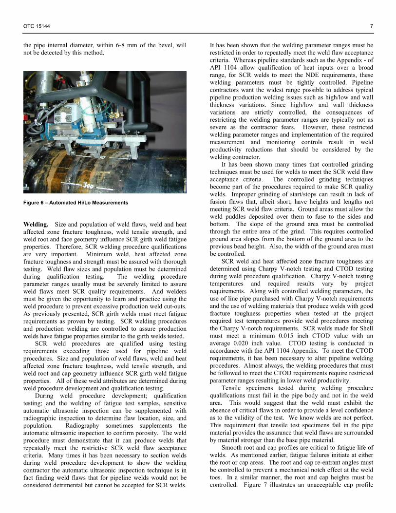
It may seem less than satisfactory that for SCR weld inspection, one needs to rely so heavily on the skill of the AUT operator. But no system software is perfect, and it is in fact the skill of the AUT operator together with built-in safety nets, such as TOFD supplementing pulse-echo interpretation, that make or break an SCR inspection system. The critical nature of SCR welds makes statistical evaluation of inspection methods, and use of probabilistic methods difficult. Much has been said about NDE Reliability assessment and defining so-called “Probability of Detection” (Appendix 5 in Ref. 5 and Ref. 6). The problem with SCR welds is that even if just 1 out of 100 defects gets undersized, and it happens to be grossly undersized, this could be the critical defect. So while statistically two different AUT systems could look alike, but one system has no errors over 1 mm, and the other system has many errors much less than 1 mm, but also a few errors over 2 mm, and if a size over 2 mm can lead to a critical defect, one has to also take a deterministic approach in comparing AUT systems. One can compare two systems based on comparing POD’s, but one would also have to further require that none of the defect sizing errors can exceed a certain critical value. Impacts of Bevel Design on AUT. If the open root, typical 27-32 degree bevel, is utilized for the welding process, simple pulse/echo probes are used for inspection. For this inspection approach, changes in wall thickness have no significant impact since the probe sets translate up or down the bevel face, with the same optimized inspection angle, as the thickness changes. Figure 10 illustrates how wall thickness changes have minimal impact on inspection.
Figure 10 -- Minimum Impact on UT due to wall Thickness Variations
The major controls that must be implemented when using this bevel configuration are:
- Assure that the calibration standard is constructed using the thickest wall to be inspected. Using the thickest wall assures that there is adequate coverage
for thinner wall pipe encountered. - Assure that the wall thickness variation is not so large
that the root or cap channels are still sensitive for their respective inspection zones. Typically the root and cap areas use different probe angles compared to the fill region, and inspection in these two areas depends on the “corner effect” for accurately sizing the critical small defects at or near the ID or OD surface.
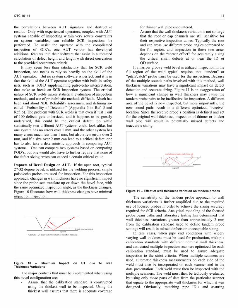
If a narrow groove weld bevel is utilized, inspection in the fill region of the weld typical requires that “tandem” or “pitch/catch” probe pairs be used for the inspection. Because of the multiple sounds paths involved with this method, wall thickness variations may have a significant impact on defect detection and accurate sizing. Figure 11 is an exaggeration of how a significant change in wall thickness may cause the tandem probe pairs to be ineffective for inspection. A different area of the bevel is now inspected, but more importantly, the new sound paths result in a different optimized “receive” location. Since the receive probe’s position is defined and set for the original wall thickness, inspection of thinner or thicker wall pipe will result in potentially missed defects and inaccurate sizing.
Figure 11 -- Effect of wall thickness variation on tandem probes
The sensitivity of the tandem probe approach to wall thickness variations is further amplified due to the required use of focused probes in order to achieve the sizing accuracy required for SCR criteria. Analytical modeling of the focused probe beam paths and laboratory testing has determined that wall thickness variations greater than approximately 2 mm from the calibration standard used to define tandem probe settings will result in missed defects or unacceptable sizing.
In rare cases, when pipe end conditions with widely varying wall thickness must be used for production, multiple calibration standards with different nominal wall thickness, and associated multiple inspection scanners optimized for each calibration standard, must be used to assure adequate inspection to the strict criteria. When multiple scanners are used, automatic thickness measurements on each side of the weld must also be incorporated on each scanner and in the data presentation. Each weld must then be inspected with the multiple scanners. The weld must then be tediously evaluated by using only those parts of data from the particular scanner that equate to the appropriate wall thickness for which it was designed. Obviously, matching pipe ID’s and assuring

14 OTC 15144
minimum wall thickness variations is a critical requirement for effective and efficient inspection to SCR criteria. Summary and Conclusions This paper has reviewed critical issues and approaches to assure consistent production and inspection quality of SCR welds. Included in the discussion were: fatigue considerations, such as fracture mechanics analyses and fatigue qualification testing; pipe end preparations, including mill tolerances, sorting of pipe ends and counter boring; and welding and inspection concerns, such as critical defect sizes for AUT.
• While SCR’s are a cost effective and relatively simple means to connect flowlines and pipelines to floating production units in deep water, welding and NDE issues require a considerable amount of effort. This effort is often underestimated by client and pipelay contractor alike.
• A system approach must be taken to SCR design, procurement, fabrication and offshore construction. A design provided, or pipe procured in isolation of consideration of offshore construction issues may cause costly remedial work, quite often on critical path. The same applies to integration of fracture mechanic analyses with the particulars of the weld inspection system to be used.
• Shell prefers to take a modified workmanship approach to establish allowable weld defect sizes for SCR’s. The results of the Fracture Mechanics (FM) analyses do not drive allowable defect sizes. Instead, sizing capabilities of the inspection system drive allowable defect sizes, coupled with expectations of what a good welding process is capable of producing. The results of the FM analyses then become a check point, and in practice, there is often a fairly large margin between what is acceptable from a FM standpoint and what is defined as acceptable to the contractor. The intention is to produce high quality welds, but the project engineer or field representative will have some leeway to adjust criteria offshore, should particular conditions make this prudent.
• Pipe end preparation is one of the most difficult issues to deal with, with far reaching implications for weld quality and inspection. This becomes even more difficult when the riser pipe is to be reeled. While counter boring in this case may improve weld alignment, it may also increase bending strains, and the net effect may be negative rather than positive. The paper presents two approaches: measure and sort pipe, and measure and machine. In practice, a combination of both methods is often required.
• Shell’s overall philosophy for pipeline, but especially riser welding, is that it is better to prevent weld flaws than to inspect for them. This places the burden on the contractor to produce very high quality welds. This can only be achieved if the contractor changes his production philosophy to one that emphasizes quality over speed. Shell’s experience over the past 10 years with SCR welding has shown that such high
quality welds can indeed be achieved, without unduly compromising offshore cycle time.
• One of the biggest advantages of making high quality welds with few flaws, is that it is much easier to inspect for such flaws than if a weld contains multiple and often interacting flaws. The inspection system must be capable of inspecting for very small flaw sizes. There is controversy in the industry – some say that inspection accuracies of 0.5 mm are simply not possible. Shell’s experience is that it is possible. But all pieces of the system must be aligned: Weld alignment must be good; a weld process must be used that produces inherently clean welds; the welders must pay extraordinary attention to grinding techniques and weld profile, particularly in the cap region; the proper transducers must be used; and the AUT technician, with not only understanding of his inspection system, but also with knowledge of the welding process, must interpret the weld.
• Finally, a rigid approach to construction of SCR’s, especially when they are welded offshore, can cause more risk during construction, than a flexible one. If the client has a challenging set of acceptance criteria, and the contractor has practiced sufficiently to generally meet the tough standards, it may be beneficial to both the client and the contractor, to have a second set of criteria that are acceptable when conditions warrant it. Judgment is required of the client representative to allow judicial use of such a set of less conservative criteria.
References
1) Venkataraman, G., “Reeled Risers: Deepwater and Dynamic Considerations”, Offshore Technology Conference, OTC 13016, May 2001, Houston.
2) Kopp, F., Venkataraman, G., Rand, G.: “Steel Catenary Riser Welding and NDE Procedures and Weld Acceptance Criteria”, Deepwater Offshore Technology Conference, DOT 1997, The Hague, The Netherlands.
3) Kopp, F., Perkins, G., Stevens, D., Prentice, G.: “High Resolution Sizing Capabilities Required for Automated Ultrasonic Inspection of Offshore Pipeline and Catenary Riser Welds”, 4th International Conference Deepwater Pipeline and Riser Technology, Clarion Technical Conferences, March 28-29, 2001, Houston.
4) Kim, D. S., Kopp, F.:“Fatigue Life Assessment of Steel Catenary Riser Using Fracture Mechanics”, Proceedings of the International Welding Conference, 1998, Taiwan.
5) DNV OS F101 (2000) – Submarine Pipeline Systems 6) Forli, O.: “Qualification of AUT for Offshore
Pipelaying and the Role of NDE Reliability”, Proceedings of the 3rd European-American Workshop on Reliability of NDE, Berlin, September 10-13, 2002.


![Drilling Riser[1]](https://img.pdfslide.us/doc/110x75/55267215550346d36e8b4d99/drilling-riser1.jpg)