Embed Size (px)
Citation preview

PRODUCT SERIES
VPR Series VPRX Series VPRE Series VPRP Series VPRC Series

2
Valent Air Management Products
Valent® Air Management Systems designs and
manufactures reliable, high-outdoor-air
ventilators. Our business focuses on
responding to the needs of our customers —
consulting engineers, contractors, and building
owners. With dedicated pre- and post-sale
application engineering support, we are here to
help you with the design, installation, ongoing
operation, and maintenance of our products.
RELIABILITY
When it comes to our products, reliability is key.
To deliver on this promise, Valent invests in the
following areas:
Best-in-class components including Digital
Scroll™ compressors, modulating direct-
drive plenum fans, and 2″ foam-injected,
double-wall casing construction
Factory-provided microprocessor controls
and proven sequences of control
Comprehensive, system-focused, operation
run testing prior to shipment
PRODUCT SERIES
VPR / VPRX Series
These comprehensive, packaged rooftops are
capable of handling up to 100% outdoor air in
heating, cooling, or dehumidification mode.
VPRX series includes a powered exhaust fan
module to relieve space pressure.
VPRE Series
VPRE packaged rooftops provide air-to-air
sensible and latent energy recovery through an
integral enthalpy wheel. With onboard heating
and cooling, the VPRE is capable of delivering
neutral air or responding directly to the needs of
the space.
VPRP Series
Sensible energy recovery is accomplished
using an air-to-air, flat-plate heat exchanger.
This platform also provides cooling and heating
for total ventilation capability. The all-aluminum
heat exchanger has extremely low leakage
between airstreams and is well-suited toward
process applications.
VPRC Series
Sensible and latent energy recovery is achieved
through an air-to-air flat-plate heat exchanger
paired with heating and cooling. Elimination of
moving parts in the heat exchanger reduces
maintenance requirements compared to a
traditional enthalpy wheel.
3
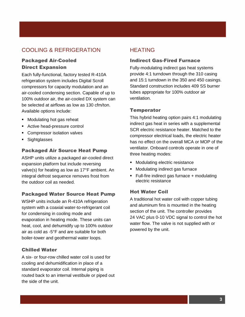
COOLING & REFRIGERATION
Packaged Air-Cooled
Direct Expansion
Each fully-functional, factory tested R-410A
refrigeration system includes Digital Scroll
compressors for capacity modulation and an
air-cooled condensing section. Capable of up to
100% outdoor air, the air-cooled DX system can
be selected at airflows as low as 130 cfm/ton.
Available options include:
Modulating hot gas reheat
Active head-pressure control
Compressor isolation valves
Sightglasses
Packaged Air Source Heat Pump
ASHP units utilize a packaged air-cooled direct
expansion platform but include reversing
valve(s) for heating as low as 17°F ambient. An
integral defrost sequence removes frost from
the outdoor coil as needed.
Packaged Water Source Heat Pump
WSHP units include an R-410A refrigeration
system with a coaxial water-to-refrigerant coil
for condensing in cooling mode and
evaporation in heating mode. These units can
heat, cool, and dehumidify up to 100% outdoor
air as cold as -5°F and are suitable for both
boiler-tower and geothermal water loops.
Chilled Water
A six- or four-row chilled water coil is used for
cooling and dehumidification in place of a
standard evaporator coil. Internal piping is
routed back to an internal vestibule or piped out
the side of the unit.
HEATING
Indirect Gas-Fired Furnace
Fully-modulating indirect gas heat systems
provide 4:1 turndown through the 310 casing
and 15:1 turndown in the 350 and 450 casings.
Standard construction includes 409 SS burner
tubes appropriate for 100% outdoor air
ventilation.
Temperator
This hybrid heating option pairs 4:1 modulating
indirect gas heat in series with a supplemental
SCR electric resistance heater. Matched to the
compressor electrical loads, the electric heater
has no effect on the overall MCA or MOP of the
ventilator. Onboard controls operate in one of
three heating modes:
Modulating electric resistance
Modulating indirect gas furnace
Full-fire indirect gas furnace + modulating electric resistance
Hot Water Coil
A traditional hot water coil with copper tubing
and aluminum fins is mounted in the heating
section of the unit. The controller provides
24 VAC plus 0-10 VDC signal to control the hot
water flow. The valve is not supplied with or
powered by the unit.

4
VPR / VPRX Series
110/210/310 Air-Cooled DX / Air Source Heat Pump
1. Outdoor air intake hood
2. Exhaust fan hood (VPRX only)
3. Air-cooled condensing section
4. Compressor access door
5. Electrical and controls access door
6. Lifting lug (typical quantity 4)
7. Heater access panel
8. Supply fan access door
9. Condensate drain connection (1.125″ dia.)
10. Evaporator and reheat coil access door
11. Supply air filter, return air damper, and outdoor air damper access door
110/210/310 Chilled Water / Water Source Heat Pump
1. Outdoor air intake hood
2. Exhaust fan hood (VPRX only)
3. Refrigeration access panels (WSHP only)
4. Compressor or chilled water connection access door
5. Electrical and controls access door
6. Lifting lug (typical quantity 4)
7. Coaxial heat exchanger access panel (WSHP only)
8. Supply fan access door
9. Condensate drain connection (1.125″ dia.)
10. Evaporator and reheat coil access door
11. Supply air filter, return air damper, and outdoor air damper access door
Dimensions
A B C D E
110 30.0 49.0 119.0 21.5 57.0
210 30.0 61.0 121.0 23.5 64.0
310 30.0 68.0 131.0 33.5 84.0
Dimensions
A B C D E
110 14.0 49.0 119.0 21.5 57.0
210 14.0 61.0 121.0 23.5 64.0
310 14.0 68.0 131.0 33.5 84.0
5
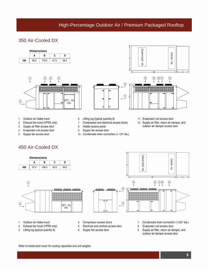
High-Percentage Outdoor Air / Premium Packaged Rooftop
350 Air-Cooled DX
1. Outdoor air intake hood
2. Exhaust fan hood (VPRX only)
3. Supply air filter access door
4. Evaporator coil access door
5. Supply fan access door
6. Lifting lug (typical quantity 6)
7. Compressor and electrical access doors
8. Heater access panel
9. Supply fan access door
10. Condensate drain connection (1.125″ dia.)
11. Evaporator coil access door
12. Supply air filter, return air damper, and outdoor air damper access door
450 Air-Cooled DX
1. Outdoor air intake hood
2. Exhaust fan hood (VPRX only)
3. Lifting lug (typical quantity 6)
4. Compressor access doors
5. Electrical and controls access door
6. Supply fan access door
7. Condensate drain connection (1.625″ dia.)
8. Evaporator coil access door
9. Supply air filter, return air damper, and outdoor air damper access door
Dimensions
A B C D
350 96.0 176.0 47.0 99.0
Dimensions
A B C D
450 97.0 199.0 55.0 99.0
Refer to inside back cover for cooling capacities and unit weights.
6
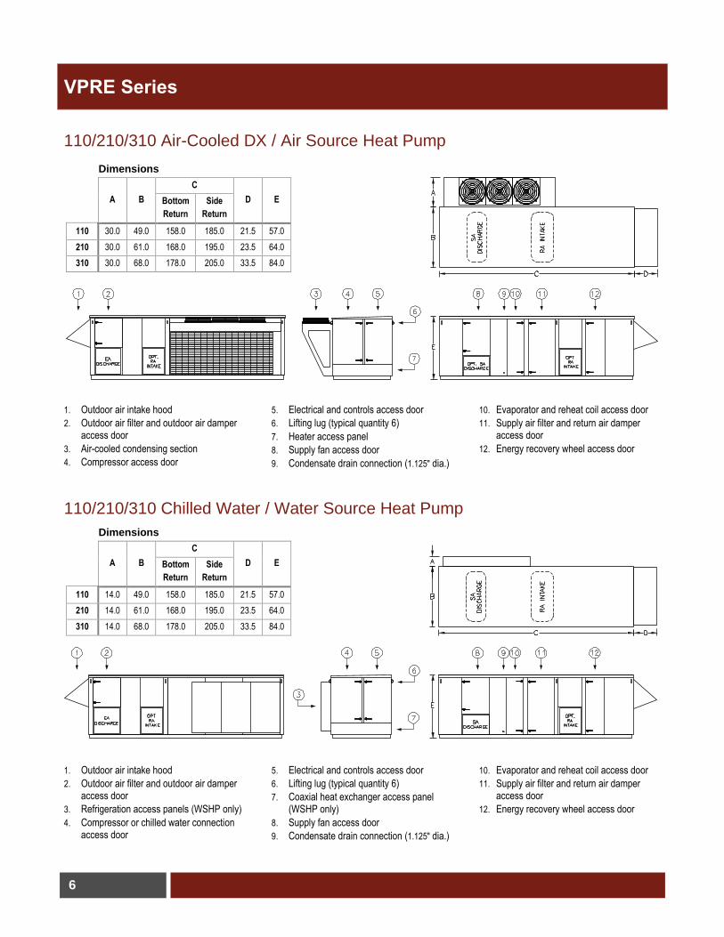
VPRE Series
110/210/310 Air-Cooled DX / Air Source Heat Pump
1. Outdoor air intake hood
2. Outdoor air filter and outdoor air damper access door
3. Air-cooled condensing section
4. Compressor access door
5. Electrical and controls access door
6. Lifting lug (typical quantity 6)
7. Heater access panel
8. Supply fan access door
9. Condensate drain connection (1.125″ dia.)
10. Evaporator and reheat coil access door
11. Supply air filter and return air damper access door
12. Energy recovery wheel access door
110/210/310 Chilled Water / Water Source Heat Pump
1. Outdoor air intake hood
2. Outdoor air filter and outdoor air damper access door
3. Refrigeration access panels (WSHP only)
4. Compressor or chilled water connection access door
5. Electrical and controls access door
6. Lifting lug (typical quantity 6)
7. Coaxial heat exchanger access panel (WSHP only)
8. Supply fan access door
9. Condensate drain connection (1.125″ dia.)
10. Evaporator and reheat coil access door
11. Supply air filter and return air damper access door
12. Energy recovery wheel access door
Dimensions
A B
C
D E
Bottom
Return
Side
Return
110 30.0 49.0 158.0 185.0 21.5 57.0
210 30.0 61.0 168.0 195.0 23.5 64.0
310 30.0 68.0 178.0 205.0 33.5 84.0
Dimensions
A B
C
D E
Bottom
Return
Side
Return
110 14.0 49.0 158.0 185.0 21.5 57.0
210 14.0 61.0 168.0 195.0 23.5 64.0
310 14.0 68.0 178.0 205.0 33.5 84.0

7
Total Energy Recovery with Energy Wheel
350 Air-Cooled DX
1. Outdoor air intake hood
2. Outdoor air filter and outdoor air damper access door
3. Supply air filter access door
4. Evaporator coil access door
5. Supply fan access door
6. Lifting lug (typical quantity 8)
7. Compressor and electrical access doors
8. Heater access panel
9. Supply fan access door
10. Condensate drain connection (1.125″ dia.)
11. Evaporator coil access door
12. Supply air filter and return air damper access door
13. Energy recovery wheel access door
14. Outdoor air filter and outdoor air damper access door
Dimensions
A B C D
350 96.0 248.0 47.0 99.0
Refer to inside back cover for cooling capacities and unit weights.
8
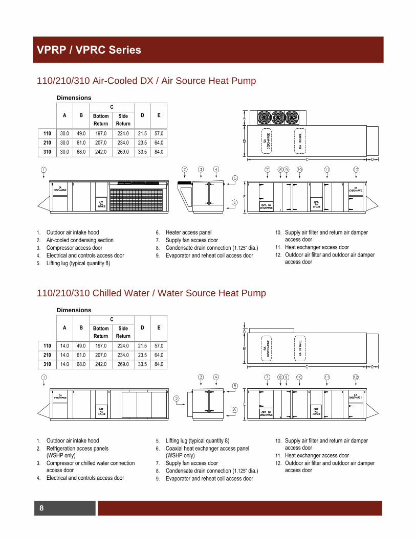
VPRP / VPRC Series
110/210/310 Air-Cooled DX / Air Source Heat Pump
1. Outdoor air intake hood
2. Air-cooled condensing section
3. Compressor access door
4. Electrical and controls access door
5. Lifting lug (typical quantity 8)
6. Heater access panel
7. Supply fan access door
8. Condensate drain connection (1.125″ dia.)
9. Evaporator and reheat coil access door
10. Supply air filter and return air damper access door
11. Heat exchanger access door
12. Outdoor air filter and outdoor air damper access door
110/210/310 Chilled Water / Water Source Heat Pump
1. Outdoor air intake hood
2. Refrigeration access panels (WSHP only)
3. Compressor or chilled water connection access door
4. Electrical and controls access door
5. Lifting lug (typical quantity 8)
6. Coaxial heat exchanger access panel (WSHP only)
7. Supply fan access door
8. Condensate drain connection (1.125″ dia.)
9. Evaporator and reheat coil access door
10. Supply air filter and return air damper access door
11. Heat exchanger access door
12. Outdoor air filter and outdoor air damper access door
Dimensions
A B
C
D E
Bottom
Return
Side
Return
110 30.0 49.0 197.0 224.0 21.5 57.0
210 30.0 61.0 207.0 234.0 23.5 64.0
310 30.0 68.0 242.0 269.0 33.5 84.0
Dimensions
A B
C
D E
Bottom
Return
Side
Return
110 14.0 49.0 197.0 224.0 21.5 57.0
210 14.0 61.0 207.0 234.0 23.5 64.0
310 14.0 68.0 242.0 269.0 33.5 84.0
9
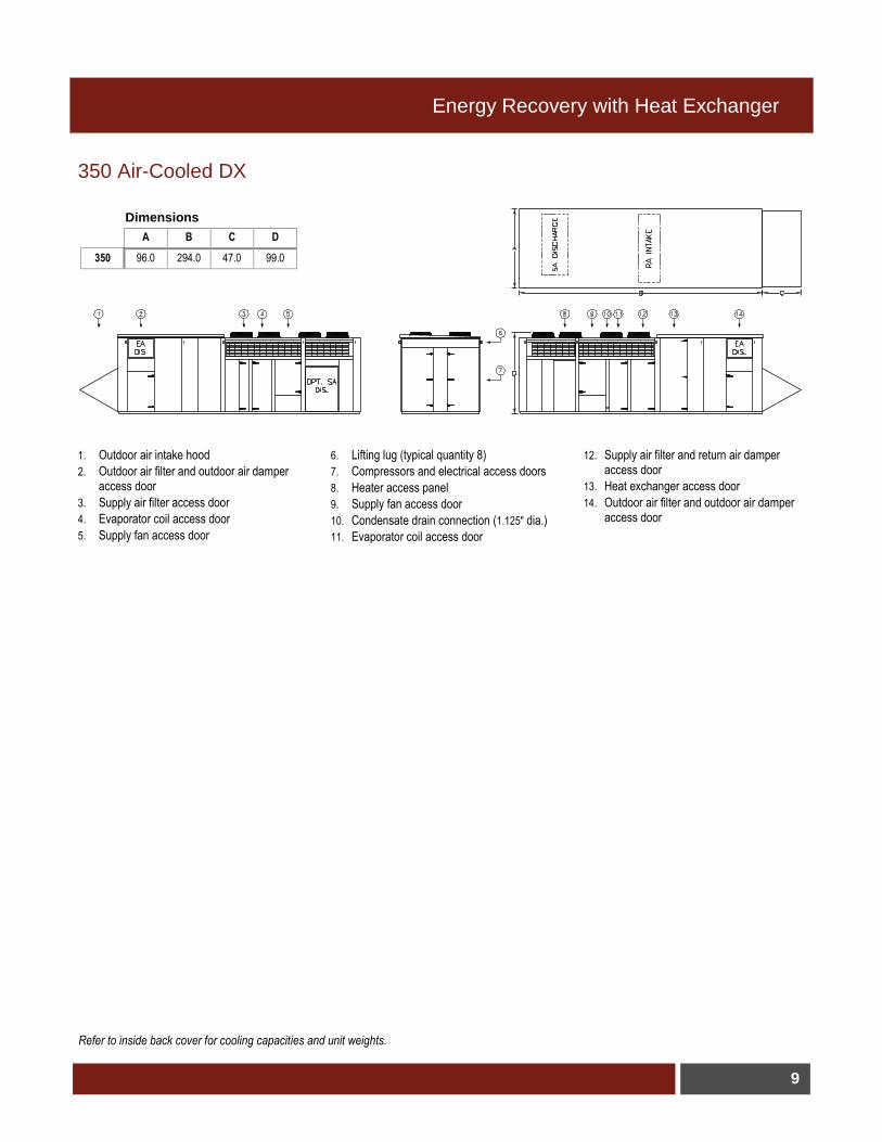
Energy Recovery with Heat Exchanger
350 Air-Cooled DX
1. Outdoor air intake hood
2. Outdoor air filter and outdoor air damper access door
3. Supply air filter access door
4. Evaporator coil access door
5. Supply fan access door
6. Lifting lug (typical quantity 8)
7. Compressors and electrical access doors
8. Heater access panel
9. Supply fan access door
10. Condensate drain connection (1.125″ dia.)
11. Evaporator coil access door
12. Supply air filter and return air damper access door
13. Heat exchanger access door
14. Outdoor air filter and outdoor air damper access door
Dimensions
A B C D
350 96.0 294.0 47.0 99.0
Refer to inside back cover for cooling capacities and unit weights.
10
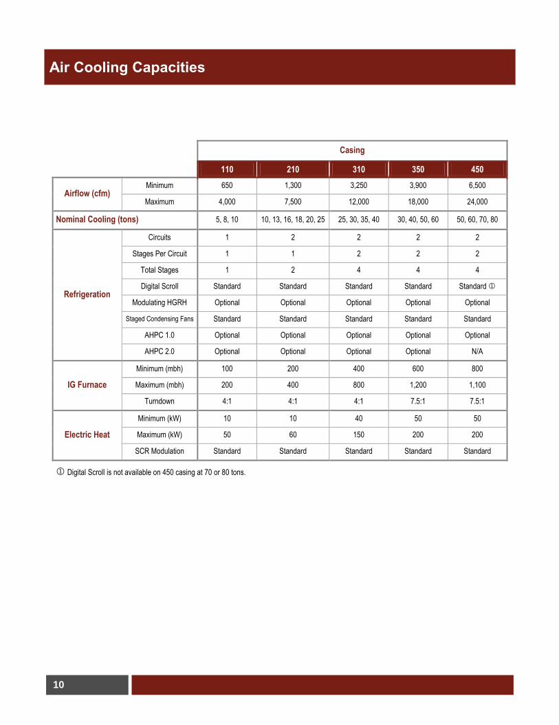
Air Cooling Capacities
Casing
110 210 310 350 450
Airflow (cfm) Minimum 650 1,300 3,250 3,900 6,500
Maximum 4,000 7,500 12,000 18,000 24,000
Nominal Cooling (tons) 5, 8, 10 10, 13, 16, 18, 20, 25 25, 30, 35, 40 30, 40, 50, 60 50, 60, 70, 80
Refrigeration
Circuits 1 2 2 2 2
Stages Per Circuit 1 1 2 2 2
Total Stages 1 2 4 4 4
Digital Scroll Standard Standard Standard Standard Standard
Modulating HGRH Optional Optional Optional Optional Optional
Staged Condensing Fans Standard Standard Standard Standard Standard
AHPC 1.0 Optional Optional Optional Optional Optional
AHPC 2.0 Optional Optional Optional Optional N/A
IG Furnace
Minimum (mbh) 100 200 400 600 800
Maximum (mbh) 200 400 800 1,200 1,100
Turndown 4:1 4:1 4:1 7.5:1 7.5:1
Electric Heat
Minimum (kW) 10 10 40 50 50
Maximum (kW) 50 60 150 200 200
SCR Modulation Standard Standard Standard Standard Standard
Digital Scroll is not available on 450 casing at 70 or 80 tons.
11
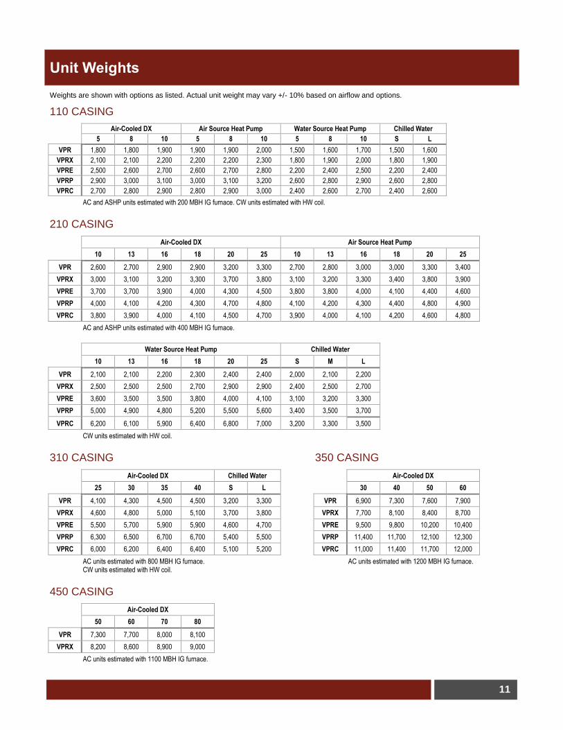
Unit Weights
Weights are shown with options as listed. Actual unit weight may vary +/- 10% based on airflow and options.
110 CASING
Air-Cooled DX Air Source Heat Pump Water Source Heat Pump Chilled Water
5 8 10 5 8 10 5 8 10 S L
VPR 1,800 1,800 1,900 1,900 1,900 2,000 1,500 1,600 1,700 1,500 1,600
VPRX 2,100 2,100 2,200 2,200 2,200 2,300 1,800 1,900 2,000 1,800 1,900
VPRE 2,500 2,600 2,700 2,600 2,700 2,800 2,200 2,400 2,500 2,200 2,400
VPRP 2,900 3,000 3,100 3,000 3,100 3,200 2,600 2,800 2,900 2,600 2,800
VPRC 2,700 2,800 2,900 2,800 2,900 3,000 2,400 2,600 2,700 2,400 2,600
AC and ASHP units estimated with 200 MBH IG furnace. CW units estimated with HW coil.
210 CASING
Air-Cooled DX Air Source Heat Pump
10 13 16 18 20 25 10 13 16 18 20 25
VPR 2,600 2,700 2,900 2,900 3,200 3,300 2,700 2,800 3,000 3,000 3,300 3,400
VPRX 3,000 3,100 3,200 3,300 3,700 3,800 3,100 3,200 3,300 3,400 3,800 3,900
VPRE 3,700 3,700 3,900 4,000 4,300 4,500 3,800 3,800 4,000 4,100 4,400 4,600
VPRP 4,000 4,100 4,200 4,300 4,700 4,800 4,100 4,200 4,300 4,400 4,800 4,900
VPRC 3,800 3,900 4,000 4,100 4,500 4,700 3,900 4,000 4,100 4,200 4,600 4,800
AC and ASHP units estimated with 400 MBH IG furnace.
Water Source Heat Pump Chilled Water
10 13 16 18 20 25 S M L
VPR 2,100 2,100 2,200 2,300 2,400 2,400 2,000 2,100 2,200
VPRX 2,500 2,500 2,500 2,700 2,900 2,900 2,400 2,500 2,700
VPRE 3,600 3,500 3,500 3,800 4,000 4,100 3,100 3,200 3,300
VPRP 5,000 4,900 4,800 5,200 5,500 5,600 3,400 3,500 3,700
VPRC 6,200 6,100 5,900 6,400 6,800 7,000 3,200 3,300 3,500
CW units estimated with HW coil.
310 CASING
Air-Cooled DX Chilled Water
25 30 35 40 S L
VPR 4,100 4,300 4,500 4,500 3,200 3,300
VPRX 4,600 4,800 5,000 5,100 3,700 3,800
VPRE 5,500 5,700 5,900 5,900 4,600 4,700
VPRP 6,300 6,500 6,700 6,700 5,400 5,500
VPRC 6,000 6,200 6,400 6,400 5,100 5,200
AC units estimated with 800 MBH IG furnace. CW units estimated with HW coil.
350 CASING
Air-Cooled DX
30 40 50 60
VPR 6,900 7,300 7,600 7,900
VPRX 7,700 8,100 8,400 8,700
VPRE 9,500 9,800 10,200 10,400
VPRP 11,400 11,700 12,100 12,300
VPRC 11,000 11,400 11,700 12,000
AC units estimated with 1200 MBH IG furnace.
450 CASING
Air-Cooled DX
50 60 70 80
VPR 7,300 7,700 8,000 8,100
VPRX 8,200 8,600 8,900 9,000
AC units estimated with 1100 MBH IG furnace.

(800)789-8550
©October 2013 Valent®
Valent® is a business of Unison™ Comfort Technologies